EP2895404B1 - Cartridge, system and method for preparation of beverages - Google Patents
Cartridge, system and method for preparation of beveragesDownload PDFInfo
- Publication number
- EP2895404B1 EP2895404B1EP13773897.7AEP13773897AEP2895404B1EP 2895404 B1EP2895404 B1EP 2895404B1EP 13773897 AEP13773897 AEP 13773897AEP 2895404 B1EP2895404 B1EP 2895404B1
- Authority
- EP
- European Patent Office
- Prior art keywords
- cartridge
- filter
- cup
- side wall
- shaped body
- Prior art date
- Legal status (The legal status is an assumption and is not a legal conclusion. Google has not performed a legal analysis and makes no representation as to the accuracy of the status listed.)
- Active
Links
- 235000013361beverageNutrition0.000titleclaimsdescription68
- 238000002360preparation methodMethods0.000titleclaimsdescription20
- 238000000034methodMethods0.000titleclaimsdescription11
- 230000002093peripheral effectEffects0.000claimsdescription26
- 239000004615ingredientSubstances0.000claimsdescription22
- 239000000463materialSubstances0.000claimsdescription20
- 239000012736aqueous mediumSubstances0.000claimsdescription19
- 239000000706filtrateSubstances0.000claimsdescription17
- -1polyethylenePolymers0.000claimsdescription12
- 230000004888barrier functionEffects0.000claimsdescription8
- 239000004698PolyethyleneSubstances0.000claimsdescription7
- 229920000573polyethylenePolymers0.000claimsdescription7
- 239000004793PolystyreneSubstances0.000claimsdescription4
- 238000004891communicationMethods0.000claimsdescription4
- 239000012530fluidSubstances0.000claimsdescription4
- 229920002223polystyrenePolymers0.000claimsdescription4
- 238000003780insertionMethods0.000claimsdescription3
- 230000037431insertionEffects0.000claimsdescription3
- 239000002648laminated materialSubstances0.000claimsdescription2
- 239000002609mediumSubstances0.000description6
- QVGXLLKOCUKJST-UHFFFAOYSA-Natomic oxygenChemical compound[O]QVGXLLKOCUKJST-UHFFFAOYSA-N0.000description4
- 239000004715ethylene vinyl alcoholSubstances0.000description4
- 229910052760oxygenInorganic materials0.000description4
- 239000001301oxygenSubstances0.000description4
- 239000000843powderSubstances0.000description4
- XLYOFNOQVPJJNP-UHFFFAOYSA-NwaterSubstancesOXLYOFNOQVPJJNP-UHFFFAOYSA-N0.000description4
- 239000004743PolypropyleneSubstances0.000description3
- 235000013336milkNutrition0.000description3
- 239000008267milkSubstances0.000description3
- 210000004080milkAnatomy0.000description3
- 229920001155polypropylenePolymers0.000description3
- 229920000219Ethylene vinyl alcoholPolymers0.000description2
- 230000015572biosynthetic processEffects0.000description2
- 239000002775capsuleSubstances0.000description2
- 230000015556catabolic processEffects0.000description2
- 229920002678cellulosePolymers0.000description2
- 239000001913celluloseSubstances0.000description2
- 235000013365dairy productNutrition0.000description2
- 238000006731degradation reactionMethods0.000description2
- 230000000694effectsEffects0.000description2
- RZXDTJIXPSCHCI-UHFFFAOYSA-Nhexa-1,5-diene-2,5-diolChemical groupOC(=C)CCC(O)=CRZXDTJIXPSCHCI-UHFFFAOYSA-N0.000description2
- 239000000203mixtureSubstances0.000description2
- 239000000123paperSubstances0.000description2
- 230000035515penetrationEffects0.000description2
- 239000000047productSubstances0.000description2
- 238000007789sealingMethods0.000description2
- 102000014171Milk ProteinsHuman genes0.000description1
- 108010011756Milk ProteinsProteins0.000description1
- 229920000881Modified starchPolymers0.000description1
- 239000004368Modified starchSubstances0.000description1
- 239000004677NylonSubstances0.000description1
- 239000004952PolyamideSubstances0.000description1
- 229920001328Polyvinylidene chloridePolymers0.000description1
- 229920000297RayonPolymers0.000description1
- 241001122767TheaceaeSpecies0.000description1
- 239000004411aluminiumSubstances0.000description1
- 229910052782aluminiumInorganic materials0.000description1
- 230000004323axial lengthEffects0.000description1
- 239000012141concentrateSubstances0.000description1
- 229920001577copolymerPolymers0.000description1
- YSXLJTGZMRNQSG-UHFFFAOYSA-Ldisodium;6-amino-5-[[2-[4-[2-[4-[2-[(2-amino-5-sulfonatonaphthalen-1-yl)diazenyl]phenyl]sulfonyloxyphenyl]propan-2-yl]phenoxy]sulfonylphenyl]diazenyl]naphthalene-1-sulfonateChemical compound[Na+].[Na+].C1=CC=C2C(N=NC3=CC=CC=C3S(=O)(=O)OC3=CC=C(C=C3)C(C)(C=3C=CC(OS(=O)(=O)C=4C(=CC=CC=4)N=NC=4C5=CC=CC(=C5C=CC=4N)S([O-])(=O)=O)=CC=3)C)=C(N)C=CC2=C1S([O-])(=O)=OYSXLJTGZMRNQSG-UHFFFAOYSA-L0.000description1
- 238000001035dryingMethods0.000description1
- 238000002474experimental methodMethods0.000description1
- 238000000605extractionMethods0.000description1
- 239000011888foilSubstances0.000description1
- 239000005417food ingredientSubstances0.000description1
- 238000002347injectionMethods0.000description1
- 239000007924injectionSubstances0.000description1
- 239000007788liquidSubstances0.000description1
- 229910052751metalInorganic materials0.000description1
- 239000002184metalSubstances0.000description1
- 230000004048modificationEffects0.000description1
- 238000012986modificationMethods0.000description1
- 235000019426modified starchNutrition0.000description1
- 229920001778nylonPolymers0.000description1
- 229920003023plasticPolymers0.000description1
- 239000004033plasticSubstances0.000description1
- 229920002647polyamidePolymers0.000description1
- 229920000728polyesterPolymers0.000description1
- 229920000139polyethylene terephthalatePolymers0.000description1
- 239000005020polyethylene terephthalateSubstances0.000description1
- 229920002635polyurethanePolymers0.000description1
- 239000004814polyurethaneSubstances0.000description1
- 239000004800polyvinyl chlorideSubstances0.000description1
- 229920000915polyvinyl chloridePolymers0.000description1
- 239000005033polyvinylidene chlorideSubstances0.000description1
- 239000011148porous materialSubstances0.000description1
- 235000008476powdered milkNutrition0.000description1
- 230000008569processEffects0.000description1
- 235000018102proteinsNutrition0.000description1
- 102000004169proteins and genesHuman genes0.000description1
- 108090000623proteins and genesProteins0.000description1
- 230000009467reductionEffects0.000description1
- 230000000717retained effectEffects0.000description1
- 238000000926separation methodMethods0.000description1
- 235000020183skimmed milkNutrition0.000description1
- 238000001694spray dryingMethods0.000description1
- 235000008939whole milkNutrition0.000description1
Images


Classifications
- A—HUMAN NECESSITIES
- A23—FOODS OR FOODSTUFFS; TREATMENT THEREOF, NOT COVERED BY OTHER CLASSES
- A23F—COFFEE; TEA; THEIR SUBSTITUTES; MANUFACTURE, PREPARATION, OR INFUSION THEREOF
- A23F3/00—Tea; Tea substitutes; Preparations thereof
- A23F3/16—Tea extraction; Tea extracts; Treating tea extract; Making instant tea
- A23F3/18—Extraction of water soluble tea constituents
- A—HUMAN NECESSITIES
- A47—FURNITURE; DOMESTIC ARTICLES OR APPLIANCES; COFFEE MILLS; SPICE MILLS; SUCTION CLEANERS IN GENERAL
- A47J—KITCHEN EQUIPMENT; COFFEE MILLS; SPICE MILLS; APPARATUS FOR MAKING BEVERAGES
- A47J31/00—Apparatus for making beverages
- A47J31/24—Coffee-making apparatus in which hot water is passed through the filter under pressure, i.e. in which the coffee grounds are extracted under pressure
- A47J31/34—Coffee-making apparatus in which hot water is passed through the filter under pressure, i.e. in which the coffee grounds are extracted under pressure with hot water under liquid pressure
- B—PERFORMING OPERATIONS; TRANSPORTING
- B65—CONVEYING; PACKING; STORING; HANDLING THIN OR FILAMENTARY MATERIAL
- B65D—CONTAINERS FOR STORAGE OR TRANSPORT OF ARTICLES OR MATERIALS, e.g. BAGS, BARRELS, BOTTLES, BOXES, CANS, CARTONS, CRATES, DRUMS, JARS, TANKS, HOPPERS, FORWARDING CONTAINERS; ACCESSORIES, CLOSURES, OR FITTINGS THEREFOR; PACKAGING ELEMENTS; PACKAGES
- B65D85/00—Containers, packaging elements or packages, specially adapted for particular articles or materials
- B65D85/70—Containers, packaging elements or packages, specially adapted for particular articles or materials for materials not otherwise provided for
- B65D85/804—Disposable containers or packages with contents which are mixed, infused or dissolved in situ, i.e. without having been previously removed from the package
- B65D85/8043—Packages adapted to allow liquid to pass through the contents
- B65D85/8055—Means for influencing the liquid flow inside the package
- B—PERFORMING OPERATIONS; TRANSPORTING
- B65—CONVEYING; PACKING; STORING; HANDLING THIN OR FILAMENTARY MATERIAL
- B65D—CONTAINERS FOR STORAGE OR TRANSPORT OF ARTICLES OR MATERIALS, e.g. BAGS, BARRELS, BOTTLES, BOXES, CANS, CARTONS, CRATES, DRUMS, JARS, TANKS, HOPPERS, FORWARDING CONTAINERS; ACCESSORIES, CLOSURES, OR FITTINGS THEREFOR; PACKAGING ELEMENTS; PACKAGES
- B65D85/00—Containers, packaging elements or packages, specially adapted for particular articles or materials
- B65D85/70—Containers, packaging elements or packages, specially adapted for particular articles or materials for materials not otherwise provided for
- B65D85/804—Disposable containers or packages with contents which are mixed, infused or dissolved in situ, i.e. without having been previously removed from the package
- B65D85/8043—Packages adapted to allow liquid to pass through the contents
- B65D85/8061—Filters
- B—PERFORMING OPERATIONS; TRANSPORTING
- B65—CONVEYING; PACKING; STORING; HANDLING THIN OR FILAMENTARY MATERIAL
- B65D—CONTAINERS FOR STORAGE OR TRANSPORT OF ARTICLES OR MATERIALS, e.g. BAGS, BARRELS, BOTTLES, BOXES, CANS, CARTONS, CRATES, DRUMS, JARS, TANKS, HOPPERS, FORWARDING CONTAINERS; ACCESSORIES, CLOSURES, OR FITTINGS THEREFOR; PACKAGING ELEMENTS; PACKAGES
- B65D85/00—Containers, packaging elements or packages, specially adapted for particular articles or materials
- B65D85/70—Containers, packaging elements or packages, specially adapted for particular articles or materials for materials not otherwise provided for
- B65D85/804—Disposable containers or packages with contents which are mixed, infused or dissolved in situ, i.e. without having been previously removed from the package
Definitions
- the present applicationrelates to cartridges, systems and methods for preparation of beverages.
- Cartridges for use in the preparation of beveragesare well known.
- a cartridge for use in a beverage preparation machinewhich, in use, is pierced by a piercing element of the beverage preparation machine to allow hot water to flow through the cartridge to brew a beverage medium such as roasted ground coffee.
- US2010/0028495Such cartridges and beverage systems are often used in domestic and workplace settings. It is desirable by consumers for each beverage to be dispensed as quickly as possible. However, especially for beverages requiring extraction of ingredients (such as roast and ground coffee), it has been found that a better beverage is produced where the beverage ingredients are compacted and subjected to relatively high pressures. This tends to require filters having a small pore size which results in flow rates through the cartridges which are relatively slow.
- WO-A-01/60712describes a beverage filter cartridge having a cup shaped outer container and a piercable lid. The beverage medium is stored in a first chamber and the cover is piercable to accommodate an injection of liquid into the first chamber.
- the filter elementis provided between the first chamber and second chamber, the bottom wall of which is piercable to accommodate an outflow of the beverage for the second chamber.
- a lower section of the side wall of the outer containeris configured to provide a plurality of circumferentially spaced flutes.
- the present disclosureprovides a cartridge, containing one or more beverage ingredients, and comprising:
- the lateral expansion of the cup-shaped bodyhelps to ensure that the filtrate channels remain unblocked and hence allow a faster flow.
- expansion of the filtermay allow a larger filter area to be obtained which can also reduce brew times.
- the cup-shaped bodymay comprise a polymeric material.
- the cup-shaped bodymay comprise a laminated material.
- the cup-shaped bodymay comprise a laminate of polystyrene and polyethylene.
- the cup-shaped bodymay be formed from a laminate having layers of polystyrene, ethylene vinyl alcohol (EVOH) and polyethylene.
- EVOHethylene vinyl alcohol
- the cup-shaped bodymay comprise a barrier layer.
- the barrier layermay form one layer of a laminate structure of the cup-shaped body.
- the barrier layermay be substantially impermeable to oxygen/air and/or moisture.
- the barrier layeracts to preserve the contents of the cartridge from potential degradation due to exposure to oxygen/air and/or moisture.
- An example of a suitable barrier layeris EVOH.
- the filtermay be formed from a sheet material that may be formed into a cup-shape having a side wall and a base, wherein the filter may comprise a plurality of sections where the sheet material includes overlying sections when secured to the cup-shaped body and prior to introduction of the aqueous medium.
- the filtermay be configured to be laterally expandable by movement of the sheet material.
- the filtermay be configured to be longitudinally expandable by movement of the overlying sheet material.
- the cartridgemay further comprise a guard element located in the filtrate volume; wherein the guard element is separately-formed from the cup-shaped body and located within the filtrate volume to define an outlet zone, the guard element being interposed between the filter and the outlet zone; wherein the guard element is configured to prevent encroachment of the filter into the outlet zone such that in use on full extension of a piercing element of a beverage preparation apparatus the piercing element is enabled to be placed in fluid communication with the outlet zone without the piercing element contacting the guard element or filter.
- the guard elementmay be configured to provide physical support to at least a portion of the filter in use to limit or preclude axial expansion of the filter.
- the guard elementmay comprise a filter support surface and at least one strut portion for spacing the filter support surface from the piercing surface of the cartridge, wherein a distal end of said strut portion may be abutted into an angle formed between the side wall and the base.
- the filtermay comprise an upper rim that is connected at or near a lid-end of the peripheral side wall and/or between the peripheral side wall and the lid and may further comprise a filter side wall that is unconnected to the peripheral side wall.
- the present disclosurealso provides a system comprising a cartridge as described above and a beverage preparation machine; wherein the beverage preparation machine comprises:
- the present disclosurealso provides a method of forming a beverage from a cartridge as described above, the method using a beverage preparation machine having an inlet piercer, an outlet piercer and a holder for the cartridge, the method comprising the steps of:
- Suitable materials for the filterinclude woven and non-woven materials, paper, and cellulose as well as plastics such as polypropylene and polyethylene.
- the paper or cellulose materialmay contain fibres of another material, for example, polypropylene or polyethylene.
- the lidmay be formed from polyethylene, polypropylene, polyesters including polyethylene terephthalate, polyvinyl chloride, polyvinylidene chloride, polyamides including nylon, polyurethane, paper, viscose and/or a metal foil.
- the lidmay comprise a laminate, be metallised or formed of copolymers.
- the lidcomprises a polyethylene-aluminium laminate.
- the beverage mediumis an extractable/infusible product such as roasted ground coffee or leaf tea.
- the beverage mediummay alternatively be a water-soluble ingredient such as instant spray-dried or freeze-dried coffee, a chocolate powder, a milk powder or a creamer powder.
- Milk powdersmay include dried skimmed milk, part-skimmed milk, and whole milk, dried milk protein concentrates, isolates, and fractions, or any combination thereof.
- Creamer powdersmay be manufactured from dairy and/or non-dairy food ingredients and typically contain emulsified fat, stabilized by protein or modified starch, dispersed in a carrier that facilitates drying, especially spray drying.
- the powdered productmay be agglomerated.
- the beverage mediummay be a mixture of extractable/infusible ingredients and water-soluble ingredients, for example a mixture of roasted ground coffee and instant freeze-dried coffee.
- the cartridge 1comprises a cup-shaped body 2, a lid 3, a filter guard 6 and a filter 8.
- the cup-shaped body 2 of Figure 1comprises a circular base 4 and an upwardly extending sidewall 5 that terminates at an upper rim 21 which defines an open upper end 20 of the cup-shaped body 2.
- the side wall 5is provided on its inner face with a plurality of flutes that include protrusions 28 that project radially inwards so as to define channels 29 interposed between the protrusions 28 which run down a substantial length of the side wall 5 from the open upper end 20 towards the base 4.
- the side wall 5is generally frustoconical in shape with a diameter at the open upper end 20 being larger than a diameter at the side wall 5 adjacent to the base 4.
- An upper region of the side wall 5 adjacent to the upper rim 21has an inwardly tapering section 22 extending downwardly from the upper rim 21.
- the side wall 5 in the region of the base 4is provided with an outwardly tapering section 23.
- An upper end of the outwardly tapering region 23connects to the remainder of the side wall 5 at an out-turned shoulder 24.
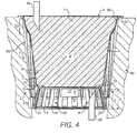
- the base 4, illustrated for example in Figure 4is generally flat and includes an annular recess 26 (illustrated in Figure 2 ) which is provided at its outer periphery at an corner 27 between the base 4 and the side wall 5.
- a flat portion 4a of the base 4provides a lower piercing surface 40 of the cartridge 1.
- the cup-shaped body 2may be formed from a laminate having layers of polystyrene, ethylene vinyl alcohol (EVOH) and polyethylene.
- the EVOH layermay act as a barrier layer which may be substantially impermeable to oxygen/air and/or moisture.
- the barrier layeracts to preserve the contents of the cartridge from potential degradation due to exposure to oxygen/air and/or moisture.
- a plurality of cup-shaped bodies 2may be stacked together prior to assembly of the cartridges 1.
- the lid 3comprises a disc that is bonded or otherwise sealed to the upper rim 21 of the cup-shaped body 2 to close the open upper end 20 of the cartridge 1.
- the lid 3defines an upper piercing surface 43 of the cartridge 1.
- the filter 8has a generally cup-shaped form having an upper filter rim 50 which is bonded or otherwise sealed to the cup-shaped body 2 (e.g. to the peripheral side wall) either at or near the upper rim 21.
- the filter rim 50is bonded between the upper rim 21 of the cup-shaped body 2 and the lid 3.
- a filter side wall 51may extend downwardly from the filter rim 50 and may be closed off at a lower end by a filter base 52 as illustrated.
- the filter 8may be moulded from a suitable material. Alternatively, the filter 8 may be formed from sheet material that is subsequently formed into the required geometric shape.
- the filter guard 6may be formed as a separate component from the cup-shaped body 2 and filter 8 and may be located at a lower end of the cup-shaped body 2 as shown in Figures 1 and 2 .
- the filter guard 6comprises an upper portion 9 defining an upper surface 10 and a circumferential wall 11 which, in the illustrated embodiment, extends downwardly and outwardly from the upper portion 9 to terminate at a lower rim 31.
- the upper portion 9comprises an outer circumferential rim 14 and an inner circumferential rim 15 which are joined together by a plurality of radial bars 12 which define interposed upper apertures 13.
- the inner rim 15defines a central aperture 16 which extends downwardly through a downwardly extending tube 17.
- the circumferential wall 11may include a plurality of axially-orientated (or substantially axially-orientated) bars 18 which extend from the lower rim 31 to the outer rim 14 and which define interposed side apertures 19.
- the filter guard 6, illustrated in Figure 3is generally frustoconical in shape with a diameter of the lower rim 31 being greater than the diameter of the outer rim 14.
- the filter guard 6may be rigid; meaning that it has sufficient structural strength so as not to undergo any substantial deformation during the use described below.
- the filter guard 6is shaped so as to be a stackable component prior to assembly of the cartridge 1.
- the downwardly extending tube 17serves to ensure that adjacent filter guards 6 are spaced slightly from one another when stacked to ensure ease of separation of each filter guard 6 from the stack.
- the lower rim 31 of the filter guard 6may be located in the annular recess 26 of the cup-shaped body 2 with the lower rim 31 held in contact with the corner 27 between the side wall 5 and the base 4.
- the filter guard 6is first inserted into the open topped cup-shaped body 2 and pushed downwardly so as to engage the lower rim 31 as a push fit into contact with the corner 27 and recess 26. Insertion of the filter guard 6 in one embodiment, is accommodated by flexure of the side wall 5 to allow the relatively rigid lower rim 31 to pass the smaller diameter of the cup-shaped body 2 at the level of the out-turned shoulder 24.
- the side wall 5is resilient in nature such that once inserted past the out-turned shoulder 24 the filter guard 6 is gripped and retained by the side wall 5 in contact with the corner 27 between the base 4 and the side wall 5 without the requirement for any additional bonding or connection means.
- the filter 8is inserted into the cup-shaped body 2 through the open upper end 20 and bonded or otherwise connected to or near the upper rim 21, for example by heat sealing.
- a container volume of the cartridge 1is divided into a beverage ingredient volume B to one side of the filter 8 and a filtrate volume C to the other side of the filter 8.
- the filter guard 6is located in the filtrate volume C beneath the filter 8.
- the channels 29 formed between the flutes 28form part of the filtrate volume C as they are 'downstream' of the filter 8.
- beverage ingredients 7, such as roasted ground coffee,is filled through the open upper end 20 into the beverage ingredient volume B.
- the cartridge 1is then closed by sealing the lid 3 to the upper rim 21 with or without sandwiching of the filter rim 50 therebetween. Two or more of the assembly steps described above may be combined into a single assembly process step.
- the filter base 52when assembled the filter base 52 is physically supported by the upper surface 10 of the filter guard 6.
- the upper surface 10 of the filter guard 6is configured to ensure that the material of the filter 8 does not extend into a portion of the filtrate volume C which can be considered an outlet zone D of the cartridge 1.
- the outlet zone Dis defined as the volume between the filter guard 6 and the base 4 of the cup-shaped body 2.
- filter guard 6is configured to receive the piercing element such that, when the piercing element is fully extended in use, the piercing element does not move filter guard 6.
- filter guard 6is configured to receive the piercing element such that, when the piercing element is fully extended in use, the piercing element does not contact filter guard 6.
- filter guard 6defines an aperture 56a that may be configured to receive a piercing element of a beverage preparation apparatus, such that, when the piercing element is fully extended into outlet zone D in use the piercing element is placed in fluid communication with the outlet zone D.
- the cartridge 1is inserted into a holder 58 of a beverage preparation apparatus.
- a peripheral wall of the holder 58defines a cavity that is shaped and sized to receive the cartridge 1 so that an annular expansion gap 59 exists initially between the holder and the side wall 5 of the cartridge 1.
- the annular expansion gap 59may be 2mm on each side of the cartridge 1.
- the beverage preparation machinecomprises an inlet piercing element 55 and outlet piercing element 56 which are engaged with the cartridge 1 to permit brewing and dispensation.
- the inlet piercing element 55pierces the upper piercing surface 43 of the cartridge 1 to form an inlet so as to provide fluid communication to the beverage ingredient volume B.
- the outlet piercing element 56pierces the lower piercing surface 40 of the base 4 to form an outlet to provide an exit flow path for beverage formed from the beverage ingredient 7 to leave the cartridge 1 and thereafter the beverage preparation apparatus can be dispensed to a receptacle such as a cup.
- the outlet piercing element 56may be offset from the centre of the cartridge 1 so as not to be impeded by the downwardly-extending tube 17.
- Aqueous mediumsuch as hot water
- a beverage extractis thus formed which passes through the filter 8 into the filtrate volume C.
- the beverage extractpasses through the filter side wall 51 into the channels 29 where it is able to run downwardly and into the outlet zone D via the side apertures 13 in the filter guard 6. Extract also passes through the filter 8 through the filter base 52 and into the outlet zone D through the upper apertures 13 and central aperture 16 of the filter guard 6.
- the cartridgeexpands laterally due to the internal pressurisation of the cartridge and the softening effect of the water which typically has a temperature of at least 85 degrees Celsius.
- the lateral expansionis made easier by configuring the side wall 5 to comprise the flutes 28.
- the lateral expansioncauses the annular expansion gap 59 to be reduced or even closed entirely.
- the expansion processresults in the frustoconical side wall 5 deforming into a barrel-shape as shown, for example, in Figure 11 .
- the lateral expansion of the cup-shaped body 2 of the cartridge 1has advantageously been found to lead to reduced beverage formation times, which will be discussed further below.
- the lateral expansion of the side wall 5 of the cartridge 1may be accompanied by lateral expansion of the filter 8.
- the filter 8is formed from a sheet material which is formed into a cup-shaped form by the overlapping of the sheet material as shown, for example, in Figure 8 .
- lateral expansionis accommodated by the overlapping sections of the sheet material moving relative to one another, such that the filter 8 partly unfolds.
- the presence of the filter guard 2limits or precludes axial expansion of the filter 8 downwards towards the base 4. It may be preferred to configure the filter 8, in terms of the size and arrangement of the overlapping sections, to ensure that the side wall 5 of the cup-shaped body 2 is able to expand laterally to a greater degree than the filter side wall. This helps to ensure that the channels 29 are always kept open.
- a distance d between the base 4 of the cup-shaped body 2 and the lower face of the radial bars 12 of the filter guard 6is greater than a penetration distance p of the outlet piercing element 56 into the cartridge 1. This ensures that during use the outlet piercing element 56 does not contact either the filter guard 6 or the filter 8.
- aperture 56a of filter guard 6extends from base 4 toward upper surface 10 a distance that is greater than penetration distance p.
- Figure 5shows another aspect of filter guard 6' that may be incorporated into the capsule 1 in place of the filter guard 6 of Figure 3 .
- FIG. 5shows another aspect of filter guard 6' that may be incorporated into the capsule 1 in place of the filter guard 6 of Figure 3 .
- features common to the previous aspect, in particular the configuration of the cup-shaped body 2, lid 3 and filter 8will not be described further and reference should be made to the passages above.
- the filter guard 6'may be formed as a separate component from cup-shaped body 2 and is located at a lower end of the cup-shaped body 2 as shown in Figure 6 .
- the filter guard 6'comprises an annular portion defining an upper surface 10', an outer circumferential wall 11' and an inner circumferential wall, both walls extending downwardly from the upper portion to adjoin a lower flange element.
- the lower flange elementdefines a lower rim 31'.
- a central aperture 16'is provided within the upper surface 10'.
- the inner circumferential wallcomprises a plurality of wall sections 18' which define interposed side apertures 19'.
- the filter guard 6'may be rigid meaning that it has sufficient structural strength so as not to undergo any substantial deformation during the use described below.
- Assembly of the cartridge 1is as described previously except that the filter guard 6' is inserted such that the lower rim 31' is engaged in or close to the corner 27 of the cup-shaped body 2.
- the inwardly-tapered section 23serves to maintain the filter guard 6' in the correct position.
- the filter base 52when assembled the filter base 52 is physically supported by the upper surface 10' of the filter guard 6' which ensures that the material of the filter 8 does not extend into a portion of the filtrate volume C which can be considered an outlet zone D of the cartridge 1.
- the outlet zone Dis defined as the enclosed volume between the filter guard 6' and the base 4 of the cup-shaped body 2.
- the outer circumferential wall 11'may also be provided with apertures 19' for passage of beverage flow into the outlet zone D.
- FIGS 9 and 10illustrate a second aspect of cartridge 1 according to the present disclosure. It is similar to the first aspect described above and in the following only the differences will be described. Like reference numerals have been used for like components.
- This aspectis substantially the same as the first aspect except that the cartridge 1 does not contain a filter guard 2. Instead the filter 8 is suspended and configured to be kept clear of the outlet piercing element 56 by its axial length.
- the filter 8is able to expand laterally and longitudinally downwards some way towards the base 4 of the cartridge 1. As with the first aspect this expansion of the side all of the cartridge 1 and expansion of the filter 8 has been found to be advantageous for reducing beverage formation times.
- cartridge 1Four types were prepared. Each type had a fill weight of roast and ground coffee of 9g. Ten samples of each type of cartridge were then brewed using a Cuisinart Model SS-700 beverage preparation machine, available from Cuisinart, Stamford, CT, USA. The annular expansion gap between the wall of the holder and the side wall of the cup- shaped body was approximately 2 mm. The beverage preparation machine was set to dispense a drink of 'Drink size 8' (a nominal 8oz drink size that during experiments delivered a drink weight of approximately 205-210g) and the brew time to dispense each sample was then measured.
- 'Drink size 8'a nominal 8oz drink size that during experiments delivered a drink weight of approximately 205-210g
- the cartridge typeswere as follows:
- Type 2 and Type 4 cartridgesacted as controls to highlight the technical effect of the lateral expansion of the cartridges of Types 1 and 3.
- the lateral expansion of the Type 1 cartridge 1led to a reduced brew time of 49sec compared to 52sec for the control.
- the reduction in brew timewas a very significant 10secs, from 61secs to 51 secs.
- the lateral expansion of the cup-shaped body 2helps to ensure that the channels 29 which act to drain the beverage downwards towards the base 4 of the capsule 1 remain unblocked and hence allow a faster flow.
- expansion of the filter 8allows a larger filter area to be obtained which can also reduce brew times.
Landscapes
- Engineering & Computer Science (AREA)
- Mechanical Engineering (AREA)
- Food Science & Technology (AREA)
- Life Sciences & Earth Sciences (AREA)
- Chemical & Material Sciences (AREA)
- Polymers & Plastics (AREA)
- Apparatus For Making Beverages (AREA)
- Packging For Living Organisms, Food Or Medicinal Products That Are Sensitive To Environmental Conditiond (AREA)
Description
- The present application relates to cartridges, systems and methods for preparation of beverages.
- Cartridges for use in the preparation of beverages are well known. For example, it is known to provide a cartridge for use in a beverage preparation machine which, in use, is pierced by a piercing element of the beverage preparation machine to allow hot water to flow through the cartridge to brew a beverage medium such as roasted ground coffee.
- One example is described in
US2010/0028495 . Such cartridges and beverage systems are often used in domestic and workplace settings. It is desirable by consumers for each beverage to be dispensed as quickly as possible. However, especially for beverages requiring extraction of ingredients (such as roast and ground coffee), it has been found that a better beverage is produced where the beverage ingredients are compacted and subjected to relatively high pressures. This tends to require filters having a small pore size which results in flow rates through the cartridges which are relatively slow.WO-A-01/60712 - The present disclosure provides a cartridge, containing one or more beverage ingredients, and comprising:
- a cup-shaped body having a base, a peripheral side wall and an open top;
- a lid attached to the cup-shaped body to close the open top to define a container volume, the lid being pierceable to accommodate an inflow of an aqueous medium into the container volume;
- a filter located within the container volume to divide the container volume into an ingredient chamber volume containing the one or more beverage ingredients and a filtrate volume;
- the base being pierceable to accommodate an outflow from the filtrate volume of a beverage formed from the aqueous medium and the one or more beverage ingredients;
- the peripheral side wall comprising a plurality of flutes that define a plurality of filtrate channels configured to direct beverage flow downwards towards the base of the cup-shaped body;
- wherein the cup-shaped body is configured to be laterally expandable in use when aqueous medium at a temperature of at least 85°C and a pressure of at least 20 KPa is introduced into the container volume; wherein the cup-shaped body (2) is configured to be laterally expandable by distortion of the flutes (28) of the peripheral side wall(s); and
- that the peripheral side wall(s) has a generally frustoconical shape prior to use and, after lateral expansion during use, has a generally barrel shape;
- characterised in that the peripheral side wall(5) has a thickness of 0.15 to 0.35mm and/or the base (4) has a thickness of 0.35 to 0.55mm.
- Without wanting to be bound by theory, it is believed that the lateral expansion of the cup-shaped body helps to ensure that the filtrate channels remain unblocked and hence allow a faster flow. In addition, expansion of the filter may allow a larger filter area to be obtained which can also reduce brew times.
- The cup-shaped body may comprise a polymeric material.
- The cup-shaped body may comprise a laminated material.
- For example, the cup-shaped body may comprise a laminate of polystyrene and polyethylene. In another example, the cup-shaped body may be formed from a laminate having layers of polystyrene, ethylene vinyl alcohol (EVOH) and polyethylene.
- The cup-shaped body may comprise a barrier layer. The barrier layer may form one layer of a laminate structure of the cup-shaped body. The barrier layer may be substantially impermeable to oxygen/air and/or moisture. Preferably the barrier layer acts to preserve the contents of the cartridge from potential degradation due to exposure to oxygen/air and/or moisture. An example of a suitable barrier layer is EVOH.
- In one aspect the filter may be formed from a sheet material that may be formed into a cup-shape having a side wall and a base, wherein the filter may comprise a plurality of sections where the sheet material includes overlying sections when secured to the cup-shaped body and prior to introduction of the aqueous medium.
- In use the filter may be configured to be laterally expandable by movement of the sheet material.
- In use the filter may be configured to be longitudinally expandable by movement of the overlying sheet material.
- In one aspect the cartridge may further comprise a guard element located in the filtrate volume;
wherein the guard element is separately-formed from the cup-shaped body and located within the filtrate volume to define an outlet zone, the guard element being interposed between the filter and the outlet zone;
wherein the guard element is configured to prevent encroachment of the filter into the outlet zone such that in use on full extension of a piercing element of a beverage preparation apparatus the piercing element is enabled to be placed in fluid communication with the outlet zone without the piercing element contacting the guard element or filter. - The guard element may be configured to provide physical support to at least a portion of the filter in use to limit or preclude axial expansion of the filter.
- The guard element may comprise a filter support surface and at least one strut portion for spacing the filter support surface from the piercing surface of the cartridge, wherein a distal end of said strut portion may be abutted into an angle formed between the side wall and the base.
- The filter may comprise an upper rim that is connected at or near a lid-end of the peripheral side wall and/or between the peripheral side wall and the lid and may further comprise a filter side wall that is unconnected to the peripheral side wall.
- The present disclosure also provides a system comprising a cartridge as described above and a beverage preparation machine;
wherein the beverage preparation machine comprises: - a holder for receiving a cartridge containing one or more beverage ingredients;
- an inlet piercer for piercing a lid of said cartridge for supplying an aqueous medium to the cartridge; and
- an outlet piercer for piercing a base of said cartridge for allowing outflow of a beverage formed from the one or more beverage ingredients and the aqueous medium;
- The present disclosure also provides a method of forming a beverage from a cartridge as described above, the method using a beverage preparation machine having an inlet piercer, an outlet piercer and a holder for the cartridge, the method comprising the steps of:
- inserting the cartridge into the holder, such that the cup-shaped body of the cartridge is received in a cavity bounded by a wall of the holder;
- piercing the lid of the cartridge with the inlet piercer;
- piercing the a base of the cartridge with the outlet piercer;
- injecting an aqueous medium through the inlet piercer into the cartridge to form the beverage, the aqueous medium being injected at a temperature of at least 85°C and a pressure of at least 20 KPa; and
- dispensing the beverage via the outlet piercer;
- Suitable materials for the filter include woven and non-woven materials, paper, and cellulose as well as plastics such as polypropylene and polyethylene. The paper or cellulose material may contain fibres of another material, for example, polypropylene or polyethylene.
- The lid may be formed from polyethylene, polypropylene, polyesters including polyethylene terephthalate, polyvinyl chloride, polyvinylidene chloride, polyamides including nylon, polyurethane, paper, viscose and/or a metal foil. The lid may comprise a laminate, be metallised or formed of copolymers. In one example, the lid comprises a polyethylene-aluminium laminate.
- The disclosure finds particular application where the beverage medium is an extractable/infusible product such as roasted ground coffee or leaf tea. However, the beverage medium may alternatively be a water-soluble ingredient such as instant spray-dried or freeze-dried coffee, a chocolate powder, a milk powder or a creamer powder. Milk powders may include dried skimmed milk, part-skimmed milk, and whole milk, dried milk protein concentrates, isolates, and fractions, or any combination thereof. Creamer powders may be manufactured from dairy and/or non-dairy food ingredients and typically contain emulsified fat, stabilized by protein or modified starch, dispersed in a carrier that facilitates drying, especially spray drying. The powdered product may be agglomerated. As a further alternative the beverage medium may be a mixture of extractable/infusible ingredients and water-soluble ingredients, for example a mixture of roasted ground coffee and instant freeze-dried coffee.
- Aspects of the present disclosure will now be described, by way of example only, with reference to the accompanying drawings, in which:
Figure 1 is a cross-sectional elevation of a cartridge according to one embodiment of the present disclosure;Figure 2 is a perspective cross-sectional view of the cartridge ofFigure 1 ;Figure 3 is a perspective view of a filter guard of the cartridge ofFigure 1 ;Figure 4 is a cross-sectional elevation of the cartridge ofFigure 1 during dispensation;Figure 5 a perspective view of another embodiment of a filter guard of the present disclosure;Figure 6 is a cross-sectional elevation of a cartridge containing the filter guard ofFigure 5 during dispensation;Figure 7 is a cross-sectional view through the cup-shaped body of the cartridge ofFigure 1 ;Figure 8 is a perspective view of a filter for use in one embodiment of the cartridges of the present disclosure;Figure 9 is a cross-sectional elevation of a cartridge according to another embodiment of the present disclosure;Figure 10 is a perspective cross-sectional view of the cartridge ofFigure 9 ; andFigure 11 is a side view showing the typical shape of the cartridges of the present disclosure after dispensation.- As shown in
Figure 1 , in a first aspect the cartridge 1 comprises a cup-shapedbody 2, alid 3, a filter guard 6 and afilter 8. - The cup-shaped
body 2 ofFigure 1 comprises acircular base 4 and an upwardly extendingsidewall 5 that terminates at anupper rim 21 which defines an openupper end 20 of the cup-shapedbody 2. As shown inFigures 2 and7 , theside wall 5 is provided on its inner face with a plurality of flutes that includeprotrusions 28 that project radially inwards so as to definechannels 29 interposed between theprotrusions 28 which run down a substantial length of theside wall 5 from the openupper end 20 towards thebase 4. Theside wall 5 is generally frustoconical in shape with a diameter at the openupper end 20 being larger than a diameter at theside wall 5 adjacent to thebase 4. An upper region of theside wall 5 adjacent to theupper rim 21 has an inwardly taperingsection 22 extending downwardly from theupper rim 21. In addition, theside wall 5 in the region of thebase 4 is provided with an outwardly taperingsection 23. An upper end of the outwardly taperingregion 23 connects to the remainder of theside wall 5 at an out-turnedshoulder 24. - The
base 4, illustrated for example inFigure 4 , is generally flat and includes an annular recess 26 (illustrated inFigure 2 ) which is provided at its outer periphery at ancorner 27 between thebase 4 and theside wall 5. A flat portion 4a of thebase 4 provides a lower piercingsurface 40 of the cartridge 1. - The cup-shaped
body 2 may be formed from a laminate having layers of polystyrene, ethylene vinyl alcohol (EVOH) and polyethylene. The EVOH layer may act as a barrier layer which may be substantially impermeable to oxygen/air and/or moisture. Preferably the barrier layer acts to preserve the contents of the cartridge from potential degradation due to exposure to oxygen/air and/or moisture. - A plurality of cup-shaped
bodies 2 may be stacked together prior to assembly of the cartridges 1. - The
lid 3 comprises a disc that is bonded or otherwise sealed to theupper rim 21 of the cup-shapedbody 2 to close the openupper end 20 of the cartridge 1. Thelid 3 defines an upper piercingsurface 43 of the cartridge 1. - In one embodiment, the
filter 8 has a generally cup-shaped form having an upper filter rim 50 which is bonded or otherwise sealed to the cup-shaped body 2 (e.g. to the peripheral side wall) either at or near theupper rim 21. In a non-illustrated example thefilter rim 50 is bonded between theupper rim 21 of the cup-shapedbody 2 and thelid 3. Afilter side wall 51 may extend downwardly from thefilter rim 50 and may be closed off at a lower end by afilter base 52 as illustrated. Thefilter 8 may be moulded from a suitable material. Alternatively, thefilter 8 may be formed from sheet material that is subsequently formed into the required geometric shape. - The filter guard 6 may be formed as a separate component from the cup-shaped
body 2 andfilter 8 and may be located at a lower end of the cup-shapedbody 2 as shown inFigures 1 and2 . As most clearly shown in the embodiment ofFigure 3 , the filter guard 6 comprises an upper portion 9 defining anupper surface 10 and acircumferential wall 11 which, in the illustrated embodiment, extends downwardly and outwardly from the upper portion 9 to terminate at alower rim 31. The upper portion 9 comprises an outercircumferential rim 14 and an innercircumferential rim 15 which are joined together by a plurality ofradial bars 12 which define interposedupper apertures 13. Theinner rim 15 defines acentral aperture 16 which extends downwardly through a downwardly extendingtube 17. Thecircumferential wall 11 may include a plurality of axially-orientated (or substantially axially-orientated) bars 18 which extend from thelower rim 31 to theouter rim 14 and which define interposedside apertures 19. The filter guard 6, illustrated inFigure 3 , is generally frustoconical in shape with a diameter of thelower rim 31 being greater than the diameter of theouter rim 14. - The filter guard 6 may be rigid; meaning that it has sufficient structural strength so as not to undergo any substantial deformation during the use described below.
- Advantageously, the filter guard 6 is shaped so as to be a stackable component prior to assembly of the cartridge 1. The downwardly extending
tube 17 serves to ensure that adjacent filter guards 6 are spaced slightly from one another when stacked to ensure ease of separation of each filter guard 6 from the stack. - As most clearly shown in
Figure 2 , thelower rim 31 of the filter guard 6 may be located in theannular recess 26 of the cup-shapedbody 2 with thelower rim 31 held in contact with thecorner 27 between theside wall 5 and thebase 4. - In an exemplary assembly technique for the cartridge 1 as shown in
Figure 1 , the filter guard 6 is first inserted into the open topped cup-shapedbody 2 and pushed downwardly so as to engage thelower rim 31 as a push fit into contact with thecorner 27 andrecess 26. Insertion of the filter guard 6 in one embodiment, is accommodated by flexure of theside wall 5 to allow the relatively rigidlower rim 31 to pass the smaller diameter of the cup-shapedbody 2 at the level of the out-turnedshoulder 24. Theside wall 5 is resilient in nature such that once inserted past the out-turnedshoulder 24 the filter guard 6 is gripped and retained by theside wall 5 in contact with thecorner 27 between thebase 4 and theside wall 5 without the requirement for any additional bonding or connection means. - Next, the
filter 8 is inserted into the cup-shapedbody 2 through the openupper end 20 and bonded or otherwise connected to or near theupper rim 21, for example by heat sealing. - As shown in
Figure 1 , with thefilter 8 in place a container volume of the cartridge 1 is divided into a beverage ingredient volume B to one side of thefilter 8 and a filtrate volume C to the other side of thefilter 8. The filter guard 6 is located in the filtrate volume C beneath thefilter 8. Thechannels 29 formed between theflutes 28 form part of the filtrate volume C as they are 'downstream' of thefilter 8. - A portion of beverage ingredients 7, such as roasted ground coffee, is filled through the open
upper end 20 into the beverage ingredient volume B. The cartridge 1 is then closed by sealing thelid 3 to theupper rim 21 with or without sandwiching of the filter rim 50 therebetween. Two or more of the assembly steps described above may be combined into a single assembly process step. - In
Figure 1 , when assembled thefilter base 52 is physically supported by theupper surface 10 of the filter guard 6. In one embodiment, theupper surface 10 of the filter guard 6 is configured to ensure that the material of thefilter 8 does not extend into a portion of the filtrate volume C which can be considered an outlet zone D of the cartridge 1. The outlet zone D is defined as the volume between the filter guard 6 and thebase 4 of the cup-shapedbody 2. In one embodiment, filter guard 6 is configured to receive the piercing element such that, when the piercing element is fully extended in use, the piercing element does not move filter guard 6. In one embodiment, filter guard 6 is configured to receive the piercing element such that, when the piercing element is fully extended in use, the piercing element does not contact filter guard 6. In one embodiment, filter guard 6 defines an aperture 56a that may be configured to receive a piercing element of a beverage preparation apparatus, such that, when the piercing element is fully extended into outlet zone D in use the piercing element is placed in fluid communication with the outlet zone D. - In use, as shown in
Figure 4 , the cartridge 1 is inserted into aholder 58 of a beverage preparation apparatus. A peripheral wall of theholder 58 defines a cavity that is shaped and sized to receive the cartridge 1 so that anannular expansion gap 59 exists initially between the holder and theside wall 5 of the cartridge 1. Theannular expansion gap 59 may be 2mm on each side of the cartridge 1. - The beverage preparation machine comprises an
inlet piercing element 55 andoutlet piercing element 56 which are engaged with the cartridge 1 to permit brewing and dispensation. As shown, theinlet piercing element 55 pierces the upper piercingsurface 43 of the cartridge 1 to form an inlet so as to provide fluid communication to the beverage ingredient volume B. Theoutlet piercing element 56 pierces the lower piercingsurface 40 of thebase 4 to form an outlet to provide an exit flow path for beverage formed from the beverage ingredient 7 to leave the cartridge 1 and thereafter the beverage preparation apparatus can be dispensed to a receptacle such as a cup. Theoutlet piercing element 56 may be offset from the centre of the cartridge 1 so as not to be impeded by the downwardly-extendingtube 17. - Aqueous medium, such as hot water, is injected into the cartridge 1 through the
inlet piercing element 55 to contact the beverage medium 7. A beverage extract is thus formed which passes through thefilter 8 into the filtrate volume C. The beverage extract passes through thefilter side wall 51 into thechannels 29 where it is able to run downwardly and into the outlet zone D via theside apertures 13 in the filter guard 6. Extract also passes through thefilter 8 through thefilter base 52 and into the outlet zone D through theupper apertures 13 andcentral aperture 16 of the filter guard 6. - During the flow of the water through the cartridge 1 the cartridge expands laterally due to the internal pressurisation of the cartridge and the softening effect of the water which typically has a temperature of at least 85 degrees Celsius. The lateral expansion is made easier by configuring the
side wall 5 to comprise theflutes 28. The lateral expansion causes theannular expansion gap 59 to be reduced or even closed entirely. As the uppermost and lowermost portions of theside wall 8 are more resilient to lateral expansion, the expansion process results in thefrustoconical side wall 5 deforming into a barrel-shape as shown, for example, inFigure 11 . - The lateral expansion of the cup-shaped
body 2 of the cartridge 1 has advantageously been found to lead to reduced beverage formation times, which will be discussed further below. - The lateral expansion of the
side wall 5 of the cartridge 1 may be accompanied by lateral expansion of thefilter 8. This may be particularly the case where thefilter 8 is formed from a sheet material which is formed into a cup-shaped form by the overlapping of the sheet material as shown, for example, inFigure 8 . In this case, lateral expansion is accommodated by the overlapping sections of the sheet material moving relative to one another, such that thefilter 8 partly unfolds. The presence of thefilter guard 2 limits or precludes axial expansion of thefilter 8 downwards towards thebase 4. It may be preferred to configure thefilter 8, in terms of the size and arrangement of the overlapping sections, to ensure that theside wall 5 of the cup-shapedbody 2 is able to expand laterally to a greater degree than the filter side wall. This helps to ensure that thechannels 29 are always kept open. - Advantageously, as shown in
Figure 4 , a distance d between thebase 4 of the cup-shapedbody 2 and the lower face of the radial bars 12 of the filter guard 6 is greater than a penetration distance p of theoutlet piercing element 56 into the cartridge 1. This ensures that during use theoutlet piercing element 56 does not contact either the filter guard 6 or thefilter 8. In one embodiment, aperture 56a of filter guard 6 extends frombase 4 toward upper surface 10 a distance that is greater than penetration distance p. Figure 5 shows another aspect of filter guard 6' that may be incorporated into the capsule 1 in place of the filter guard 6 ofFigure 3 . In describing this aspect, features common to the previous aspect, in particular the configuration of the cup-shapedbody 2,lid 3 andfilter 8 will not be described further and reference should be made to the passages above.- As before, the filter guard 6' may be formed as a separate component from cup-shaped
body 2 and is located at a lower end of the cup-shapedbody 2 as shown inFigure 6 . The filter guard 6' comprises an annular portion defining an upper surface 10', an outer circumferential wall 11' and an inner circumferential wall, both walls extending downwardly from the upper portion to adjoin a lower flange element. The lower flange element defines a lower rim 31'. A central aperture 16' is provided within the upper surface 10'. The inner circumferential wall comprises a plurality of wall sections 18' which define interposed side apertures 19'. - The filter guard 6' may be rigid meaning that it has sufficient structural strength so as not to undergo any substantial deformation during the use described below.
- Assembly of the cartridge 1 is as described previously except that the filter guard 6' is inserted such that the lower rim 31' is engaged in or close to the
corner 27 of the cup-shapedbody 2. As above, the inwardly-taperedsection 23 serves to maintain the filter guard 6' in the correct position. - As can be seen from
Figure 6 , when assembled thefilter base 52 is physically supported by the upper surface 10' of the filter guard 6' which ensures that the material of thefilter 8 does not extend into a portion of the filtrate volume C which can be considered an outlet zone D of the cartridge 1. The outlet zone D is defined as the enclosed volume between the filter guard 6' and thebase 4 of the cup-shapedbody 2. - Use of the cartridge 1 is as described above except that beverage extract passing through the
filter 8 is channelled to theoutlet piercing element 56 via the side apertures 19' and the annular outlet zone D. - In a modification of the above aspect, the outer circumferential wall 11' may also be provided with apertures 19' for passage of beverage flow into the outlet zone D.
Figures 9 and10 illustrate a second aspect of cartridge 1 according to the present disclosure. It is similar to the first aspect described above and in the following only the differences will be described. Like reference numerals have been used for like components.- This aspect is substantially the same as the first aspect except that the cartridge 1 does not contain a
filter guard 2. Instead thefilter 8 is suspended and configured to be kept clear of theoutlet piercing element 56 by its axial length. - Use of the cartridge 1 is as described above. However, now the
filter 8 is able to expand laterally and longitudinally downwards some way towards thebase 4 of the cartridge 1. As with the first aspect this expansion of the side all of the cartridge 1 and expansion of thefilter 8 has been found to be advantageous for reducing beverage formation times. - Four types of cartridge 1 were prepared. Each type had a fill weight of roast and ground coffee of 9g. Ten samples of each type of cartridge were then brewed using a Cuisinart Model SS-700 beverage preparation machine, available from Cuisinart, Stamford, CT, USA. The annular expansion gap between the wall of the holder and the side wall of the cup- shaped body was approximately 2 mm. The beverage preparation machine was set to dispense a drink of 'Drink size 8' (a nominal 8oz drink size that during experiments delivered a drink weight of approximately 205-210g) and the brew time to dispense each sample was then measured.
- The cartridge types were as follows:
- Type 1 - A cartridge 1. as described in the second aspect, that is without a
filter guard 2. - Type 2 - A cartridge 1 as described in the second aspect, that is without a
filter guard 2 but additionally having a collar placed around theperipheral side wall 5 of the cup-shapedbody 2 to substantially prevent any lateral expansion of the cup-shapedbody 2. - Type 3 - A cartridge 1 as described in the first aspect, that is with a
filter guard 2 as shown inFigure 3 . - Type 2 - A cartridge 1 as described in the first aspect, that is with a
filter guard 2 as shown inFigure 3 but additionally having a collar placed around theperipheral side wall 5 of the cup-shapedbody 2 to substantially prevent any lateral expansion of the cup-shapedbody 2. - Thus, the
Type 2 andType 4 cartridges acted as controls to highlight the technical effect of the lateral expansion of the cartridges ofTypes 1 and 3. - The average brew times were as follows:
Table 1 Cartridge Type Average Brew time for Ten Samples(s) Drink weight (g) 1 49 210 2 52 210 3 51 206 4 61 208 - As can be seen, the lateral expansion of the Type 1 cartridge 1 led to a reduced brew time of 49sec compared to 52sec for the control. In the case of the
Type 3 cartridge 1 the reduction in brew time was a very significant 10secs, from 61secs to 51 secs. - Without wanting to be bound by theory, it is believed that the lateral expansion of the cup-shaped body 2 (and optionally the
filter 8 within) helps to ensure that thechannels 29 which act to drain the beverage downwards towards thebase 4 of the capsule 1 remain unblocked and hence allow a faster flow. In addition, expansion of thefilter 8 allows a larger filter area to be obtained which can also reduce brew times. - Whilst the fastest brew times were obtained where a
filter guard 2 was not used, in some circumstances the advantages of using a filter guard will offset the potentially longer brew time. Even in this case, the lateral expansion has been found to be advantageous in reducing brew times by about 6%. - From the foregoing it will be appreciated that cartridges for preparation of beverages and components for such cartridges are provided.
Claims (11)
- A cartridge (1), containing one or more beverage ingredients (7), and comprising:a cup-shaped body (2) having a base (4), a peripheral side wall (5) and an open top (20);a lid (3) attached to the cup-shaped body (2) to close the open top (20) to define a container volume, the lid (3) being pierceable to accommodate an inflow of an aqueous medium into the container volume;a filter (8) located within the container volume to divide the container volume into an ingredient chamber volume (B) containing the one or more beverage ingredients (7) and a filtrate volume (C);the base (4) being pierceable to accommodate an outflow from the filtrate volume (C)of a beverage formed from the aqueous medium and the one or more beverage ingredients (7);the peripheral side wall(5) comprising a plurality of flutes (28) that define a plurality of filtrate channels (29) configured to direct beverage flow downwards towards the base (4) of the cup-shaped body (2);wherein the cup-shaped body (2) is configured to be laterally expandable in use when aqueous medium at a temperature of at least 85°C and a pressure of at least 20 KPa is introduced into the container volume;wherein the cup-shaped body (2) is configured to be laterally expandable by distortion of the flutes (28) of the peripheral side wall(5); andthe peripheral side wall(5) has a generally frustoconical shape prior to use and, after lateral expansion during use, has a generally barrel shape;characterised in that the peripheral side wall(5) has a thickness of 0.15 to 0.35mm and/or the base (4) has a thickness of 0.35 to 0.55mm.
- A cartridge (1) as claimed in claim 1 wherein the cup-shaped body (2) comprises a polymeric material, or a laminated material, preferably a laminate of polystyrene and polyethylene.
- A cartridge (1) as claimed in claim 1 wherein the cup-shaped body (2) comprises a barrier layer.
- A cartridge (1) as claimed in claim 1 wherein the filter (8) is formed from a sheet material that is formed into a cup-shape having a side wall (51) and a base (52), wherein the filter (8) comprises a plurality of sections where the sheet material includes overlying sections when secured to the cup-shaped body (2) and prior to introduction of the aqueous medium.
- A cartridge (1) as claimed in claim 4 wherein in use the filter (8) is configured to be laterally and/or longitudinally expandable by movement of the sheet material.
- A cartridge (1) as claimed in claim 1 further comprising a guard element (6) located in the filtrate volume (c);
wherein the guard element (6) is separately-formed from the cup-shaped body (2) and located within the filtrate volume (c) to define an outlet zone (D), the guard element (6) being interposed between the filter (8) and the outlet zone (D);
wherein the guard element (6) is configured to prevent encroachment of the filter (8) into the outlet zone (D) such that in use on full extension of a piercing element (56) of a beverage preparation apparatus the piercing element (56) is enabled to be placed in fluid communication with the outlet zone (D) without the piercing element (56) contacting the guard element (6) or filter (8) . - A cartridge (1) as claimed in claim 6 wherein the guard element (6) is configured to provide physical support to at least a portion of the filter (8) in use to limit or preclude axial expansion of the filter (8).
- A cartridge (1) as claimed in claim 6 wherein the guard element (6) comprises a filter support surface and at least one strut portion for spacing the filter support surface from the piercing surface of the cartridge (1), wherein a distal end of said strut portion is abutted into an angle formed between the side wall (5) and the base (4).
- A cartridge (1) as claimed in claim 1 wherein the filter (8) comprises an upper rim (50) that is connected at or near a lid-end of the peripheral side wall (5) and/or between the peripheral side wall (5) and the lid (3) and further comprises a filter side wall (51) that is unconnected to the peripheral side wall (5).
- A system comprising a cartridge (1) as claimed in claim 1 and a beverage preparation machine;
wherein the beverage preparation machine comprises:a holder (58) for receiving a cartridge (1) containing one or more beverage ingredients (7);an inlet piercing element (55) for piercing a lid of said cartridge (1) for supplying an aqueous medium to the cartridge (1); andan outlet piercing element (56) for piercing a base (4) of said cartridge (1) for allowing outflow of a beverage formed from the one or more beverage ingredients (7) and the aqueous medium;wherein the holder (58) comprises a wall defining a cavity for receiving the cartridge (1), the cavity having an internal diameter that is larger than an external diameter of at least a substantial portion of the peripheral side wall of the cartridge (1) such that on insertion of the cartridge (1) into the cavity an annular expansion gap (59) is provided between at least a substantial portion of the peripheral side wall (5) of the cartridge (1) and the wall of the holder (58). - A method of forming a beverage from a cartridge (1) as claimed in claim 1, the method using a beverage preparation machine having an inlet piercing element (55), an outlet piercing element (56) and a holder for the cartridge (1), the method comprising the steps of:inserting the cartridge (1) into the holder (58), such that the cup-shaped body (2) of the cartridge (1) is received in a cavity bounded by a wall of the holder (58);piercing the lid (3) of the cartridge (1) with the inlet piercing element (55);piercing the base of the cartridge (1) with the outlet piercing element (56);injecting an aqueous medium through the inlet piercing element (55) into the cartridge (1) to form the beverage, the aqueous medium being injected at a temperature of at least 85°C and a pressure of at least 20 KPa; anddispensing the beverage via the outlet piercing element (56);wherein due to passage of the aqueous medium through the cartridge (1) the cup-shaped body (2) is laterally expanded so that the peripheral side wall (5) of the cup-shaped body (2) including the flutes (28) has a generally barrel shape after lateral expansion.
Applications Claiming Priority (2)
| Application Number | Priority Date | Filing Date | Title |
|---|---|---|---|
| US13/612,528US20140072675A1 (en) | 2012-09-12 | 2012-09-12 | Cartridges, Systems And Methods For Preparation Of Beverages |
| PCT/US2013/058993WO2014043102A1 (en) | 2012-09-12 | 2013-09-10 | Cartridges, systems and methods for preparation of beverages |
Publications (2)
| Publication Number | Publication Date |
|---|---|
| EP2895404A1 EP2895404A1 (en) | 2015-07-22 |
| EP2895404B1true EP2895404B1 (en) | 2017-12-13 |
Family
ID=49305082
Family Applications (1)
| Application Number | Title | Priority Date | Filing Date |
|---|---|---|---|
| EP13773897.7AActiveEP2895404B1 (en) | 2012-09-12 | 2013-09-10 | Cartridge, system and method for preparation of beverages |
Country Status (13)
| Country | Link |
|---|---|
| US (1) | US20140072675A1 (en) |
| EP (1) | EP2895404B1 (en) |
| JP (1) | JP6400581B2 (en) |
| KR (2) | KR101975080B1 (en) |
| CN (1) | CN104619608B (en) |
| AU (1) | AU2013315749B2 (en) |
| BR (1) | BR112015005395B1 (en) |
| CA (1) | CA2879198C (en) |
| ES (1) | ES2661853T3 (en) |
| MX (1) | MX363335B (en) |
| RU (1) | RU2613575C2 (en) |
| TW (1) | TW201425203A (en) |
| WO (1) | WO2014043102A1 (en) |
Families Citing this family (20)
| Publication number | Priority date | Publication date | Assignee | Title |
|---|---|---|---|---|
| US11832755B2 (en)* | 2007-07-13 | 2023-12-05 | Adrian Rivera | Brewing material container for a beverage brewer |
| US10722066B2 (en)* | 2010-12-04 | 2020-07-28 | Adrian Rivera | Windowed single serving brewing material holder |
| WO2010137959A1 (en)* | 2009-06-17 | 2010-12-02 | Sara Lee/De N.V. | System and method for preparing a predetermined quantity of beverage |
| US10071851B2 (en) | 2010-07-12 | 2018-09-11 | Robert Bao Vu | Apparatus and products for producing beverages, and methods for making and using same |
| SMT201900157T1 (en)* | 2010-07-22 | 2019-05-10 | K Fee System Gmbh | Portion capsule having an identifier |
| GB2488799A (en) | 2011-03-08 | 2012-09-12 | Kraft Foods R & D Inc | Drinks Pod without Piercing of Outer Shell |
| US10450130B2 (en) | 2012-09-12 | 2019-10-22 | Kraft Foods R & D, Inc. | Cartridges, systems and methods for preparation of beverages |
| US8960078B2 (en)* | 2013-03-14 | 2015-02-24 | Keurig Green Mountain, Inc. | Reusable beverage cartridge |
| USD757536S1 (en) | 2014-10-01 | 2016-05-31 | Kraft Foods Group Brands Llc | Container |
| JP2017531476A (en)* | 2014-10-01 | 2017-10-26 | クラフト・フーズ・グループ・ブランズ・エルエルシー | Coffee pod |
| US11001436B2 (en)* | 2016-06-09 | 2021-05-11 | Keurig Green Mountain, Inc. | Beverage cartridge |
| EP3475191B1 (en)* | 2016-06-28 | 2022-04-06 | Société des Produits Nestlé S.A. | Capsule for beverage preparation machine |
| IT201600082459A1 (en)* | 2016-08-04 | 2018-02-04 | Bisio Progetti Spa | Capsule for the preparation of infusion and soluble drinks |
| CA3041722A1 (en) | 2016-11-09 | 2018-05-17 | Pepsico, Inc. | Carbonated beverage makers, methods, and systems |
| CN114803167B (en)* | 2018-06-12 | 2023-11-14 | 广东美的生活电器制造有限公司 | Capsule and beverage machine |
| US20220227574A1 (en)* | 2020-01-30 | 2022-07-21 | Sung Oh | Draining the Beverage From a Single-Serve Beverage Pod With or Without an Outlet Piercing Element |
| US20210362941A1 (en)* | 2020-05-22 | 2021-11-25 | Nexe Innovations Inc. | Beverage pod |
| CN112173371A (en)* | 2020-10-14 | 2021-01-05 | 云南合润天成生物科技有限责任公司 | Tea capsule capable of bearing high-pressure extraction |
| US11805934B1 (en)* | 2020-10-21 | 2023-11-07 | Adrian Rivera | Brewing material lid and container for a beverage brewer |
| KR102783559B1 (en)* | 2022-12-01 | 2025-03-19 | 이정영 | Container for packaging coffee drip bag |
Family Cites Families (28)
| Publication number | Priority date | Publication date | Assignee | Title |
|---|---|---|---|---|
| US2778739A (en)* | 1954-07-16 | 1957-01-22 | Sealpak Corp | Package for beverage infusion material |
| US3445237A (en)* | 1966-06-28 | 1969-05-20 | Lester Gidge | Preshaped cartridge for,and method of packaging,percolator ground coffee |
| US4867993A (en)* | 1988-02-08 | 1989-09-19 | Nordskog Robert A | Disposable beverage brewing chamber |
| KR100295123B1 (en)* | 1992-07-06 | 2001-09-17 | 뷜르 로망 엘. | Sealed flexible bag and its manufacturing method |
| US5840189A (en)* | 1992-09-16 | 1998-11-24 | Keurig, Inc. | Beverage filter cartridge |
| US6645537B2 (en)* | 2000-02-18 | 2003-11-11 | Keurig, Incorporated | Beverage filter cartridge |
| ATE268557T1 (en)* | 2000-09-06 | 2004-06-15 | Mars Uk Ltd | METHOD AND DEVICE FOR BREWING COFFEE |
| US6832542B2 (en)* | 2001-03-23 | 2004-12-21 | Nestec S.A. | Method and device for preparing a hot beverage |
| CA2421128C (en)* | 2002-03-14 | 2008-05-20 | Robert Hale | Beverage cartridge and filter assembly |
| ITMI20021087A1 (en)* | 2002-05-21 | 2003-11-21 | Sergio Tonon | CARTRIDGE FOR COFFEE AND SOLUBLE PRODUCTS APPARATUS FOR THE EXTRACTION OF BEVERAGES FROM THE CARTRIDGE AND RELATED METHOD OF PRODUCTION OF A DRINK |
| US20050051478A1 (en)* | 2003-09-10 | 2005-03-10 | Basil Karanikos | Beverage filter cartridge |
| ITBO20050249A1 (en)* | 2005-04-19 | 2006-10-20 | Aroma System S R L | PERFORMANCE OF CAPSULES AND USER EQUIPMENT TO OBTAIN EXPRESS TYPE OF INFUSIONS |
| DE502007003099D1 (en)* | 2006-08-25 | 2010-04-22 | Delica Ag | MEANS FOR PENETRATING A PORTION PACKAGING CONTAINING EXTRACTION GOODS, DEVICE FOR EXTRACTING THE EXTRACTION GUN CONTAINED IN THE PORTION PACKAGING, AND METHOD FOR PRODUCING THE MEDIUM |
| EP1894853B1 (en)* | 2006-08-30 | 2012-11-07 | Nestec S.A. | Capsule for the preparation of a beverage |
| US9271597B2 (en)* | 2007-07-13 | 2016-03-01 | ARM Enterprises | Single serving reusable brewing material holder |
| US9179797B2 (en)* | 2007-07-13 | 2015-11-10 | Adrian Rivera | Disposable single serving beverage pod adapter |
| WO2009114119A1 (en) | 2008-03-10 | 2009-09-17 | Green Mountain Coffee Roasters | Beverage cartridge |
| ES2426930T3 (en)* | 2008-04-24 | 2013-10-25 | Tconcept Company S.P.R.L. | Capsule, device and procedure for preparing infusion drinks |
| US8474368B2 (en)* | 2009-05-13 | 2013-07-02 | Curwood, Inc. | Mineral composite beverage brewing cup and cartridge |
| US9750370B2 (en)* | 2009-05-29 | 2017-09-05 | Keurig Green Mountain, Inc. | Cartridge with filter guard |
| BR112012004423A2 (en)* | 2009-08-28 | 2016-03-22 | Green Mountain Coffee Roasters Inc | "beverage cartridge and method for beverage formation using filter aid" |
| DE102009041633A1 (en)* | 2009-09-17 | 2011-06-01 | Krüger Gmbh & Co. Kg | Portion capsule and use of a portion capsule |
| DE102009058646A1 (en)* | 2009-12-16 | 2011-06-22 | Krüger GmbH & Co. KG, 51469 | Portion capsule and use of a portion capsule |
| JP2013514831A (en)* | 2009-12-18 | 2013-05-02 | グリーン マウンテン コーヒー ロースターズ,インク. | Beverage forming apparatus and method using sonic energy |
| US9085410B2 (en)* | 2010-06-10 | 2015-07-21 | Fres-Co System Usa, Inc. | Single brew beverage cartridge system including same and method of use |
| US8927037B2 (en)* | 2011-02-08 | 2015-01-06 | Kevin B. Kihnke | Disposable cartridge for brewed beverages |
| US20130156897A1 (en)* | 2011-08-10 | 2013-06-20 | David Goldstein | Beverage filter cartridge |
| KR102075814B1 (en)* | 2012-06-22 | 2020-02-10 | 터치 커피 & 베버리지스, 엘엘씨. | Beverage brewing system |
- 2012
- 2012-09-12USUS13/612,528patent/US20140072675A1/ennot_activeAbandoned
- 2013
- 2013-09-10KRKR1020157006082Apatent/KR101975080B1/enactiveActive
- 2013-09-10JPJP2015528723Apatent/JP6400581B2/ennot_activeExpired - Fee Related
- 2013-09-10CACA2879198Apatent/CA2879198C/enactiveActive
- 2013-09-10CNCN201380047379.5Apatent/CN104619608B/ennot_activeExpired - Fee Related
- 2013-09-10WOPCT/US2013/058993patent/WO2014043102A1/enactiveApplication Filing
- 2013-09-10ESES13773897.7Tpatent/ES2661853T3/enactiveActive
- 2013-09-10RURU2015108153Apatent/RU2613575C2/enactive
- 2013-09-10AUAU2013315749Apatent/AU2013315749B2/ennot_activeCeased
- 2013-09-10EPEP13773897.7Apatent/EP2895404B1/enactiveActive
- 2013-09-10BRBR112015005395-5Apatent/BR112015005395B1/ennot_activeIP Right Cessation
- 2013-09-10MXMX2015003160Apatent/MX363335B/enunknown
- 2013-09-10KRKR1020177019422Apatent/KR20170085609A/ennot_activeCeased
- 2013-09-12TWTW102132948Apatent/TW201425203A/enunknown
Also Published As
| Publication number | Publication date |
|---|---|
| MX363335B (en) | 2019-03-19 |
| AU2013315749A1 (en) | 2015-02-12 |
| KR20170085609A (en) | 2017-07-24 |
| MX2015003160A (en) | 2015-11-18 |
| AU2013315749B2 (en) | 2016-08-04 |
| CA2879198C (en) | 2019-02-19 |
| ES2661853T3 (en) | 2018-04-04 |
| CA2879198A1 (en) | 2014-03-20 |
| BR112015005395B1 (en) | 2021-01-12 |
| JP2015531631A (en) | 2015-11-05 |
| KR101975080B1 (en) | 2019-05-03 |
| WO2014043102A1 (en) | 2014-03-20 |
| CN104619608A (en) | 2015-05-13 |
| RU2613575C2 (en) | 2017-03-17 |
| KR20150041115A (en) | 2015-04-15 |
| US20140072675A1 (en) | 2014-03-13 |
| JP6400581B2 (en) | 2018-10-03 |
| EP2895404A1 (en) | 2015-07-22 |
| BR112015005395A2 (en) | 2017-07-04 |
| CN104619608B (en) | 2018-04-06 |
| RU2015108153A (en) | 2016-11-10 |
| TW201425203A (en) | 2014-07-01 |
Similar Documents
| Publication | Publication Date | Title |
|---|---|---|
| EP2895404B1 (en) | Cartridge, system and method for preparation of beverages | |
| EP2895405B1 (en) | Cartridge, system and method for preparation of beverages | |
| US11083324B2 (en) | Capsule and system for preparing a beverage by centrifugation in a beverage production device | |
| HK1178765B (en) | Capsule and system for preparing a beverage by centrifugation in a beverage production device |
Legal Events
| Date | Code | Title | Description |
|---|---|---|---|
| PUAI | Public reference made under article 153(3) epc to a published international application that has entered the european phase | Free format text:ORIGINAL CODE: 0009012 | |
| 17P | Request for examination filed | Effective date:20150112 | |
| AK | Designated contracting states | Kind code of ref document:A1 Designated state(s):AL AT BE BG CH CY CZ DE DK EE ES FI FR GB GR HR HU IE IS IT LI LT LU LV MC MK MT NL NO PL PT RO RS SE SI SK SM TR | |
| AX | Request for extension of the european patent | Extension state:BA ME | |
| RIN1 | Information on inventor provided before grant (corrected) | Inventor name:HANSEN, NICK ANDREW Inventor name:YORK, GEOFFREY Inventor name:NORTON, MARK RICHARD THOMAS | |
| DAX | Request for extension of the european patent (deleted) | ||
| RAP1 | Party data changed (applicant data changed or rights of an application transferred) | Owner name:KONINKLIJKE DOUWE EGBERTS B.V. | |
| 17Q | First examination report despatched | Effective date:20160503 | |
| GRAP | Despatch of communication of intention to grant a patent | Free format text:ORIGINAL CODE: EPIDOSNIGR1 | |
| RIC1 | Information provided on ipc code assigned before grant | Ipc:B65D 85/804 20060101AFI20170530BHEP Ipc:A47J 31/06 20060101ALN20170530BHEP | |
| RIC1 | Information provided on ipc code assigned before grant | Ipc:B65D 85/804 20060101AFI20170612BHEP Ipc:A47J 31/06 20060101ALN20170612BHEP | |
| INTG | Intention to grant announced | Effective date:20170629 | |
| GRAS | Grant fee paid | Free format text:ORIGINAL CODE: EPIDOSNIGR3 | |
| GRAA | (expected) grant | Free format text:ORIGINAL CODE: 0009210 | |
| AK | Designated contracting states | Kind code of ref document:B1 Designated state(s):AL AT BE BG CH CY CZ DE DK EE ES FI FR GB GR HR HU IE IS IT LI LT LU LV MC MK MT NL NO PL PT RO RS SE SI SK SM TR | |
| REG | Reference to a national code | Ref country code:GB Ref legal event code:FG4D | |
| REG | Reference to a national code | Ref country code:AT Ref legal event code:REF Ref document number:954140 Country of ref document:AT Kind code of ref document:T Effective date:20171215 Ref country code:CH Ref legal event code:EP | |
| REG | Reference to a national code | Ref country code:IE Ref legal event code:FG4D | |
| REG | Reference to a national code | Ref country code:DE Ref legal event code:R096 Ref document number:602013030812 Country of ref document:DE | |
| REG | Reference to a national code | Ref country code:CH Ref legal event code:NV Representative=s name:KIRKER AND CIE S.A., CH | |
| REG | Reference to a national code | Ref country code:NL Ref legal event code:FP | |
| REG | Reference to a national code | Ref country code:ES Ref legal event code:FG2A Ref document number:2661853 Country of ref document:ES Kind code of ref document:T3 Effective date:20180404 | |
| REG | Reference to a national code | Ref country code:LT Ref legal event code:MG4D | |
| PG25 | Lapsed in a contracting state [announced via postgrant information from national office to epo] | Ref country code:FI Free format text:LAPSE BECAUSE OF FAILURE TO SUBMIT A TRANSLATION OF THE DESCRIPTION OR TO PAY THE FEE WITHIN THE PRESCRIBED TIME-LIMIT Effective date:20171213 Ref country code:NO Free format text:LAPSE BECAUSE OF FAILURE TO SUBMIT A TRANSLATION OF THE DESCRIPTION OR TO PAY THE FEE WITHIN THE PRESCRIBED TIME-LIMIT Effective date:20180313 Ref country code:SE Free format text:LAPSE BECAUSE OF FAILURE TO SUBMIT A TRANSLATION OF THE DESCRIPTION OR TO PAY THE FEE WITHIN THE PRESCRIBED TIME-LIMIT Effective date:20171213 Ref country code:LT Free format text:LAPSE BECAUSE OF FAILURE TO SUBMIT A TRANSLATION OF THE DESCRIPTION OR TO PAY THE FEE WITHIN THE PRESCRIBED TIME-LIMIT Effective date:20171213 | |
| REG | Reference to a national code | Ref country code:AT Ref legal event code:MK05 Ref document number:954140 Country of ref document:AT Kind code of ref document:T Effective date:20171213 | |
| PG25 | Lapsed in a contracting state [announced via postgrant information from national office to epo] | Ref country code:LV Free format text:LAPSE BECAUSE OF FAILURE TO SUBMIT A TRANSLATION OF THE DESCRIPTION OR TO PAY THE FEE WITHIN THE PRESCRIBED TIME-LIMIT Effective date:20171213 Ref country code:GR Free format text:LAPSE BECAUSE OF FAILURE TO SUBMIT A TRANSLATION OF THE DESCRIPTION OR TO PAY THE FEE WITHIN THE PRESCRIBED TIME-LIMIT Effective date:20180314 Ref country code:BG Free format text:LAPSE BECAUSE OF FAILURE TO SUBMIT A TRANSLATION OF THE DESCRIPTION OR TO PAY THE FEE WITHIN THE PRESCRIBED TIME-LIMIT Effective date:20180313 Ref country code:RS Free format text:LAPSE BECAUSE OF FAILURE TO SUBMIT A TRANSLATION OF THE DESCRIPTION OR TO PAY THE FEE WITHIN THE PRESCRIBED TIME-LIMIT Effective date:20171213 Ref country code:HR Free format text:LAPSE BECAUSE OF FAILURE TO SUBMIT A TRANSLATION OF THE DESCRIPTION OR TO PAY THE FEE WITHIN THE PRESCRIBED TIME-LIMIT Effective date:20171213 | |
| PG25 | Lapsed in a contracting state [announced via postgrant information from national office to epo] | Ref country code:CY Free format text:LAPSE BECAUSE OF FAILURE TO SUBMIT A TRANSLATION OF THE DESCRIPTION OR TO PAY THE FEE WITHIN THE PRESCRIBED TIME-LIMIT Effective date:20171213 Ref country code:EE Free format text:LAPSE BECAUSE OF FAILURE TO SUBMIT A TRANSLATION OF THE DESCRIPTION OR TO PAY THE FEE WITHIN THE PRESCRIBED TIME-LIMIT Effective date:20171213 Ref country code:CZ Free format text:LAPSE BECAUSE OF FAILURE TO SUBMIT A TRANSLATION OF THE DESCRIPTION OR TO PAY THE FEE WITHIN THE PRESCRIBED TIME-LIMIT Effective date:20171213 Ref country code:SK Free format text:LAPSE BECAUSE OF FAILURE TO SUBMIT A TRANSLATION OF THE DESCRIPTION OR TO PAY THE FEE WITHIN THE PRESCRIBED TIME-LIMIT Effective date:20171213 | |
| PG25 | Lapsed in a contracting state [announced via postgrant information from national office to epo] | Ref country code:AT Free format text:LAPSE BECAUSE OF FAILURE TO SUBMIT A TRANSLATION OF THE DESCRIPTION OR TO PAY THE FEE WITHIN THE PRESCRIBED TIME-LIMIT Effective date:20171213 Ref country code:SM Free format text:LAPSE BECAUSE OF FAILURE TO SUBMIT A TRANSLATION OF THE DESCRIPTION OR TO PAY THE FEE WITHIN THE PRESCRIBED TIME-LIMIT Effective date:20171213 Ref country code:IS Free format text:LAPSE BECAUSE OF FAILURE TO SUBMIT A TRANSLATION OF THE DESCRIPTION OR TO PAY THE FEE WITHIN THE PRESCRIBED TIME-LIMIT Effective date:20180413 Ref country code:RO Free format text:LAPSE BECAUSE OF FAILURE TO SUBMIT A TRANSLATION OF THE DESCRIPTION OR TO PAY THE FEE WITHIN THE PRESCRIBED TIME-LIMIT Effective date:20171213 Ref country code:PL Free format text:LAPSE BECAUSE OF FAILURE TO SUBMIT A TRANSLATION OF THE DESCRIPTION OR TO PAY THE FEE WITHIN THE PRESCRIBED TIME-LIMIT Effective date:20171213 | |
| REG | Reference to a national code | Ref country code:DE Ref legal event code:R097 Ref document number:602013030812 Country of ref document:DE | |
| REG | Reference to a national code | Ref country code:FR Ref legal event code:PLFP Year of fee payment:6 | |
| PLBE | No opposition filed within time limit | Free format text:ORIGINAL CODE: 0009261 | |
| STAA | Information on the status of an ep patent application or granted ep patent | Free format text:STATUS: NO OPPOSITION FILED WITHIN TIME LIMIT | |
| 26N | No opposition filed | Effective date:20180914 | |
| PG25 | Lapsed in a contracting state [announced via postgrant information from national office to epo] | Ref country code:DK Free format text:LAPSE BECAUSE OF FAILURE TO SUBMIT A TRANSLATION OF THE DESCRIPTION OR TO PAY THE FEE WITHIN THE PRESCRIBED TIME-LIMIT Effective date:20171213 | |
| PG25 | Lapsed in a contracting state [announced via postgrant information from national office to epo] | Ref country code:SI Free format text:LAPSE BECAUSE OF FAILURE TO SUBMIT A TRANSLATION OF THE DESCRIPTION OR TO PAY THE FEE WITHIN THE PRESCRIBED TIME-LIMIT Effective date:20171213 | |
| PG25 | Lapsed in a contracting state [announced via postgrant information from national office to epo] | Ref country code:MC Free format text:LAPSE BECAUSE OF FAILURE TO SUBMIT A TRANSLATION OF THE DESCRIPTION OR TO PAY THE FEE WITHIN THE PRESCRIBED TIME-LIMIT Effective date:20171213 | |
| REG | Reference to a national code | Ref country code:BE Ref legal event code:MM Effective date:20180930 | |
| REG | Reference to a national code | Ref country code:IE Ref legal event code:MM4A | |
| PG25 | Lapsed in a contracting state [announced via postgrant information from national office to epo] | Ref country code:LU Free format text:LAPSE BECAUSE OF NON-PAYMENT OF DUE FEES Effective date:20180910 | |
| PG25 | Lapsed in a contracting state [announced via postgrant information from national office to epo] | Ref country code:IE Free format text:LAPSE BECAUSE OF NON-PAYMENT OF DUE FEES Effective date:20180910 | |
| PG25 | Lapsed in a contracting state [announced via postgrant information from national office to epo] | Ref country code:BE Free format text:LAPSE BECAUSE OF NON-PAYMENT OF DUE FEES Effective date:20180930 | |
| PG25 | Lapsed in a contracting state [announced via postgrant information from national office to epo] | Ref country code:MT Free format text:LAPSE BECAUSE OF NON-PAYMENT OF DUE FEES Effective date:20180910 | |
| PG25 | Lapsed in a contracting state [announced via postgrant information from national office to epo] | Ref country code:TR Free format text:LAPSE BECAUSE OF FAILURE TO SUBMIT A TRANSLATION OF THE DESCRIPTION OR TO PAY THE FEE WITHIN THE PRESCRIBED TIME-LIMIT Effective date:20171213 | |
| PG25 | Lapsed in a contracting state [announced via postgrant information from national office to epo] | Ref country code:PT Free format text:LAPSE BECAUSE OF FAILURE TO SUBMIT A TRANSLATION OF THE DESCRIPTION OR TO PAY THE FEE WITHIN THE PRESCRIBED TIME-LIMIT Effective date:20171213 | |
| PG25 | Lapsed in a contracting state [announced via postgrant information from national office to epo] | Ref country code:MK Free format text:LAPSE BECAUSE OF NON-PAYMENT OF DUE FEES Effective date:20171213 Ref country code:HU Free format text:LAPSE BECAUSE OF FAILURE TO SUBMIT A TRANSLATION OF THE DESCRIPTION OR TO PAY THE FEE WITHIN THE PRESCRIBED TIME-LIMIT; INVALID AB INITIO Effective date:20130910 | |
| PG25 | Lapsed in a contracting state [announced via postgrant information from national office to epo] | Ref country code:AL Free format text:LAPSE BECAUSE OF FAILURE TO SUBMIT A TRANSLATION OF THE DESCRIPTION OR TO PAY THE FEE WITHIN THE PRESCRIBED TIME-LIMIT Effective date:20171213 | |
| PGFP | Annual fee paid to national office [announced via postgrant information from national office to epo] | Ref country code:GB Payment date:20220927 Year of fee payment:10 Ref country code:DE Payment date:20220928 Year of fee payment:10 | |
| PGFP | Annual fee paid to national office [announced via postgrant information from national office to epo] | Ref country code:FR Payment date:20220926 Year of fee payment:10 | |
| PGFP | Annual fee paid to national office [announced via postgrant information from national office to epo] | Ref country code:IT Payment date:20220926 Year of fee payment:10 Ref country code:ES Payment date:20221003 Year of fee payment:10 | |
| PGFP | Annual fee paid to national office [announced via postgrant information from national office to epo] | Ref country code:CH Payment date:20221005 Year of fee payment:10 | |
| P01 | Opt-out of the competence of the unified patent court (upc) registered | Effective date:20230505 | |
| REG | Reference to a national code | Ref country code:DE Ref legal event code:R119 Ref document number:602013030812 Country of ref document:DE | |
| REG | Reference to a national code | Ref country code:CH Ref legal event code:PL | |
| GBPC | Gb: european patent ceased through non-payment of renewal fee | Effective date:20230910 | |
| PG25 | Lapsed in a contracting state [announced via postgrant information from national office to epo] | Ref country code:GB Free format text:LAPSE BECAUSE OF NON-PAYMENT OF DUE FEES Effective date:20230910 | |
| PG25 | Lapsed in a contracting state [announced via postgrant information from national office to epo] | Ref country code:CH Free format text:LAPSE BECAUSE OF NON-PAYMENT OF DUE FEES Effective date:20230930 | |
| PG25 | Lapsed in a contracting state [announced via postgrant information from national office to epo] | Ref country code:GB Free format text:LAPSE BECAUSE OF NON-PAYMENT OF DUE FEES Effective date:20230910 Ref country code:FR Free format text:LAPSE BECAUSE OF NON-PAYMENT OF DUE FEES Effective date:20230930 Ref country code:DE Free format text:LAPSE BECAUSE OF NON-PAYMENT OF DUE FEES Effective date:20240403 Ref country code:CH Free format text:LAPSE BECAUSE OF NON-PAYMENT OF DUE FEES Effective date:20230930 | |
| PGFP | Annual fee paid to national office [announced via postgrant information from national office to epo] | Ref country code:NL Payment date:20240926 Year of fee payment:12 | |
| REG | Reference to a national code | Ref country code:ES Ref legal event code:FD2A Effective date:20241031 | |
| PG25 | Lapsed in a contracting state [announced via postgrant information from national office to epo] | Ref country code:IT Free format text:LAPSE BECAUSE OF NON-PAYMENT OF DUE FEES Effective date:20230910 | |
| PG25 | Lapsed in a contracting state [announced via postgrant information from national office to epo] | Ref country code:IT Free format text:LAPSE BECAUSE OF NON-PAYMENT OF DUE FEES Effective date:20230910 | |
| PG25 | Lapsed in a contracting state [announced via postgrant information from national office to epo] | Ref country code:ES Free format text:LAPSE BECAUSE OF NON-PAYMENT OF DUE FEES Effective date:20230911 | |
| PG25 | Lapsed in a contracting state [announced via postgrant information from national office to epo] | Ref country code:ES Free format text:LAPSE BECAUSE OF NON-PAYMENT OF DUE FEES Effective date:20230911 |