EP2895358B1 - Safety belt retention device - Google Patents
Safety belt retention deviceDownload PDFInfo
- Publication number
- EP2895358B1 EP2895358B1EP13762113.2AEP13762113AEP2895358B1EP 2895358 B1EP2895358 B1EP 2895358B1EP 13762113 AEP13762113 AEP 13762113AEP 2895358 B1EP2895358 B1EP 2895358B1
- Authority
- EP
- European Patent Office
- Prior art keywords
- safety belt
- pad
- retention device
- vehicle
- belt
- Prior art date
- Legal status (The legal status is an assumption and is not a legal conclusion. Google has not performed a legal analysis and makes no representation as to the accuracy of the status listed.)
- Active
Links
Images


Classifications
- B—PERFORMING OPERATIONS; TRANSPORTING
- B60—VEHICLES IN GENERAL
- B60R—VEHICLES, VEHICLE FITTINGS, OR VEHICLE PARTS, NOT OTHERWISE PROVIDED FOR
- B60R22/00—Safety belts or body harnesses in vehicles
- B60R22/18—Anchoring devices
- B60R22/26—Anchoring devices secured to the seat
- B—PERFORMING OPERATIONS; TRANSPORTING
- B60—VEHICLES IN GENERAL
- B60R—VEHICLES, VEHICLE FITTINGS, OR VEHICLE PARTS, NOT OTHERWISE PROVIDED FOR
- B60R22/00—Safety belts or body harnesses in vehicles
- B60R22/02—Semi-passive restraint systems, e.g. systems applied or removed automatically but not both ; Manual restraint systems
- B60R22/023—Three-point seat belt systems comprising two side lower and one side upper anchoring devices
- B—PERFORMING OPERATIONS; TRANSPORTING
- B60—VEHICLES IN GENERAL
- B60R—VEHICLES, VEHICLE FITTINGS, OR VEHICLE PARTS, NOT OTHERWISE PROVIDED FOR
- B60R22/00—Safety belts or body harnesses in vehicles
- B60R22/12—Construction of belts or harnesses
- B60R22/14—Construction of belts or harnesses incorporating enlarged restraint areas, e.g. vests, nets, crash pads, optionally for children
- B—PERFORMING OPERATIONS; TRANSPORTING
- B60—VEHICLES IN GENERAL
- B60R—VEHICLES, VEHICLE FITTINGS, OR VEHICLE PARTS, NOT OTHERWISE PROVIDED FOR
- B60R22/00—Safety belts or body harnesses in vehicles
- B60R22/30—Coupling devices other than buckles, including length-adjusting fittings or anti-slip devices
- B—PERFORMING OPERATIONS; TRANSPORTING
- B60—VEHICLES IN GENERAL
- B60R—VEHICLES, VEHICLE FITTINGS, OR VEHICLE PARTS, NOT OTHERWISE PROVIDED FOR
- B60R22/00—Safety belts or body harnesses in vehicles
- B60R2022/008—Belts; Fixing thereof specially adapted for pregnant users
Definitions
- the present inventionrelates to a safety belt retention device, where the safety belt retention device will prevent a transversal belt section of a vehicle safety belt, e.g. a three-point safety belt, from sliding up onto a user's abdomen and exerting pressure against the user's abdomen in the event of abrupt braking or vehicle crash, which may result in injuries to internal organs, especially the womb and foetus in pregnant women, or of external auxiliary organs of stoma operated persons.
- a vehicle safety belte.g. a three-point safety belt
- Such vehicle safety beltsare designed as a three-point safety belt, where the three-point safety belt includes a transversal belt section designed to extend across the abdomen of the user and a diagonal belt section designed to extend across the user's upper body over one shoulder so as to limit forward movement in the event of a braking or a collision.
- the diagonal belt sectiontends to pull the safety belt upwardly so that the transversal belt section tends to ride up across the passenger's stomach. This can cause serious abdominal injury to the user and is particularly dangerous for pregnant women.
- US 5.005.865describe a seatbelt positioning assembly for positioning a seatbelt of a vehicle along the lower abdominal region of a pregnant person so as to avoid crossing over the womb.
- the seatbelt positioning assemblycomprises a seat pad adapted to be positioned on the seat of the vehicle being secured thereto by a securing strap fastened about the seat back portion.
- a sleeveis removably fitted along a portion of the length of the seatbelt wherein a pair of positioning straps connected to and extending from the seat pad are adapted for attachment with a bottom edge of the sleeve so as to pull the sleeve and, accordingly, the attached seatbelt downwardly in position along the lower abdominal region of the user.
- EP 456.745describes a device for use with a safety belt and a seat in a vehicle to prevent a lap portion of the safety belt from sliding up to and pressing against the user's abdomen in case of a collision.
- the lap portion of the safety beltis releasably fastened to a connecting means, which is fastened between the user's thighs to a sitting support.
- US 6.935.700 B2discloses a safety belt retention device according to the preamble of claim 1.
- a further object of the present inventionis to provide a safety belt retention device with a fastening means system, such that the safety belt retention device can be used in various vehicle models and car seat configurations.
- a safety belt retention device as defined in claim 1is provided.
- the pad of the safety belt retention devicemay comprise several panels, for instance three panels, where at least one of the panels may be manufactured from a less flexible material in order to provide certain stiffness in the safety belt retention device.
- the stiffer panelmay then be arranged between a softer top and bottom panel. Furthermore, the stiffer panel may then serve as an anchor point for the safety belt receiving means and the fastening means system.
- the pad of the safety belt retention devicemay comprise fewer or more panels.
- the safety belt receiving means and the fastening means systemare fastened to the stiffer panel in appropriate ways, for instance by stitching, gluing etc.
- the top panel and bottom panelmay preferably be manufactured of a soft and insulating material of great strength and resistance to tearing.
- the bottom panelmay be manufactured from a material that will provide friction between the pad and the upper seat surface of the vehicle seat when the pad is arranged on the vehicle seat.
- an underside of the bottom panelmay be provided with Velcro over at least a part of its surface.
- the pad of the safety belt retention devicemay also be provided with a rim around its periphery in order to protect the pad against wear and tear.
- the fastening means system of the safety belt retention devicecomprises a tensioning belt and a plurality of snap hooks, where the tensioning belt is used to secure the safety belt retention device around the vehicle seat, while the snap hooks are used to secure the safety belt retention device to standard anchoring points in the vehicle.
- the fastening means systemwill thereby provide a more flexible solution, as the safety belt retention device according to the present invention may be used in both a front seat and a back seat of the vehicle and may furthermore be used with standard anchoring points in the vehicle or a vehicle without such standard anchoring points, as the safety belt retention device can then be secured around the vehicle seat.
- the tensioning beltcomprises a male strap section and a female strap section, where the male and female strap sections can be connected through a male and female buckle.
- One end of the male strap sectionmay be provided with a ring element, while the opposite end of the male strap section may be provided with a male buckle.
- the female strap sectionmay be provided with a similar ring element on one end, while the opposite end may be provided with a female buckle.
- the snap hookswhich are fastened to the pad, preferably to the stiffer panel of the pad, are provided with a spring element, whereby the tensioning belt can be attached and disengaged easily to and from the snap hooks.
- fastening means systemmay be comprised of other elements, for instance other types of hooks, Isofix connectors, connecting means etc., as long as the purpose of the fastening means system is obtained.
- the safety belt receiving meansmay comprise an elastic strap, where one end of the elastic strap in appropriate ways is connected to the stiffer panel of the pad, while the opposite end of the elastic strap is connected to a sleeve.
- the sleeveis provided with at least one push button, such that the sleeve can be opened to receive the transversal belt section of the vehicle safety belt.
- the elastic strapmay also be provided with one or more elastic elements that will tend to press the safety belt receiving means down into abutment with the pad, such that the safety belt receiving means will not have to be removed before the user sits on the pad.
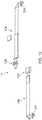
- Figure 1Ashows a top view of a safety belt retention device 1 according to the present invention, where the safety belt retention device 1 comprises a pad 2 that is adapted to be located on an upper seat surface US of a vehicle seat S in a vehicle. The pad 2 will then be placed on the upper seat surface US with its underside U. A top side T of the pad 2 will then serve as a sitting area for a passenger, for instance a pregnant woman or a stoma operated person, when the safety belt retention device 1 is in use.
- the pad 2is provided with a mainly straight rear edge R, where this mainly straight rear edge R, when in use, will be located in a transition between the upper seat surface US of the vehicle seat S and a back rest BR of the vehicle seat S when the pad 2 is arranged on the seat S.
- the front edge of the pad 2is provided with a rounded edge E.
- the safety belt retention device 1also can be provided with other shapes.
- a safety belt receiving means 3is connected to the pad 2 in appropriate ways, where the safety belt receiving means 3 is arranged on the pad 2 in such a way that the safety belt receiving means 3 will be located between the legs of the passenger when the safety belt retention device 1 is in use.
- the safety belt receiving means 3comprises an elastic strap 4 and a sleeve 5 .
- the sleeve 5is provided with a plurality of push buttons 6, such that the sleeve 5 can be opened to receive a transversal belt section 7 of a vehicle safety belt 8, for instance a three-point safety belt.
- push buttons 6are pressed to "lock" the transversal belt section 7 in the sleeve 5.
- the sleeve 5 of the safety belt receiving means 3will then retain the transversal belt section 7, while the elastic strap 4 of the safety belt receiving means 3 will, due to its elastic properties, tend to pull the transversal belt section 7 away from the passenger's abdomen.
- the safety belt retention device 1also comprises a fastening means system F, where one part of the fastening means system F comprises two snap hooks 9, while the other part of the fastening means system F comprises a tensioning belt 11. If the safety belt retention device is to be used in a front seat of the vehicle, then the tensioning belt 11 is connected to the snap hooks 9, whereby the tensioning belt 11 is arranged around the vehicle seat S in order to secure the safety belt retention device 1 to the vehicle seat S.
- the tensioning belt 11is disengaged from the snap hooks 9, whereby the snap hooks 9 are connected to standard anchorage points 10 arranged in the vehicle in order to secure the safety belt retention device 1 to the back seat of the vehicle.
- the mainly straight rear edge R of the pad 2will then be provided with two snap hooks 9, where the snap hooks 9 are arranged with a distance between each other.
- the snap hooks 9are furthermore adapted to cooperate with standard anchorage points 10 in the vehicle seat S.
- Such snap hooks 9are well known in the art and will therefore not be discussed further herein.
- the snap hooks 9may be connected directly to the pad 2, or may be connected to the pad 2 through straps (not shown).
- the tensioning belt 11is shown in figure 1C , where it can be seen that the tensioning belt comprises a male strap section 11A and a female strap section 11B.
- One end of the male strap section 11Ais provided with a ring element 12A, while the opposite end of the male strap section 11A is provided with a male buckle 12B.
- one end of the female strap section 11Bis provided with the ring element 12A, while the opposite end of the female strap section 11B is provided with a female buckle 12C.
- the male and the female strap sections 11A, 11Bcan therefore be connected to each other through the male and female buckle 12B, 12C and the length of the tensioning belt 11 can be adjusted through the tightening of the male strap section 11A through the male buckle 12B.
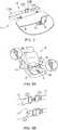
- the tensioning belt 11can be connected to the pad 2 through the snap hooks 9, as each of the ring element 12A of the male and female strap sections 11A, 11B then is to be connected to its respective snap hook 9. This can be seen in figure 3 .
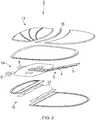
- Figure 2shows, in an exploded view, the different elements of the pad 2, where it can be seen that the pad 2 is comprised of a top panel 13, a stiffer middle panel 14 and a bottom panel 15.
- the top panel 13 and the bottom panel 15are two-piece panels, where the pieces are connected to each other through an intermediate part 16 or through a plurality of Velcro strips 17.
- the middle panel 14is manufactured from a stiffer material than the top and bottom panel 13, 15, the middle panel 14 is used as an anchor point for both the snap hooks 9 and the safety belt receiving means 3.
- the snap hooks 9will then in appropriate ways be connected to an underside of the middle panel 14, while the belt receiving means 3 will, in similar ways, be connected to an upper side of the middle panel 14.
- the top panel 13 and bottom panel 15may preferably be manufactured of a soft and insulating material of great strength and resistance to tearing.
- the snap hooks 9may for instance be connected to the middle panel 14 through a strap and ring attachment (not shown), in such a way that the snap hooks 9 may be pivoted about the strap and ring attachment, whereby the safety belt retention device 1 to a greater extent can be adapted to different vehicles and vehicle models.
- the safety belt receiving means 3comprises, as mentioned above, an elastic strap 4 and a sleeve 5 provided with push buttons 6. Due to the properties of the elastic strap 4, the elastic strap 4 can be extended a certain length, such that the safety belt receiving means 3 can be adjusted to the passenger's abdomen. This will be advantageous when a pregnant women's abdomen is growing. However, the elastic strap 4 will also try to resume its length before it was extended, whereby this will pull the transversal belt section 7 of the vehicle safety belt 8 away from the passenger's abdomen.
- the elastic strap 4is also provided with one or more elastic elements (not shown) that will tend to straighten out the elastic strap 4, such that the elastic strap 4 and the sleeve 5 are pressed down towards the pad 2. The passenger will then not have to remove the safety belt receiving means away from the sitting area of the pad 2, as the safety belt receiving means 3 already is arranged correctly.
- Figure 3shows the safety belt retention device 1 according to the present invention, where it can be seen that the male and female strap sections 11A, 11B of the tensioning belt 11 are connected to each other and that the tensioning belt 11 furthermore is connected to the pad 2 through the ring elements 12A.
- Figure 4Aillustrates how the safety belt retention device 1 according to the present invention is used in the front seat of the vehicle.
- the pad 2is loosely placed on the upper seat surface US of the front seat S and is pressed down towards the vehicle seat S by the weight of the passenger in a critical situation of braking or a vehicle collision when the influence of forces occurs.
- the fastening means system Fis used to secure the pad 2 around the vehicle seat S.
- the male strap section 11A and the female strap section 11B, already being fastened to the snap hooks 9 through the ring element 12Awill then be arranged around the vehicle seat S, whereafter the male and female strap sections 11A, 11B will be connected through the male buckle 12A and female buckle 12C.
- the tensioning belt 11can then be tightened by pulling the end of the male strap section 11A, as seen in figure 4B .
- FIGS 4C and 4Dshow how the safety belt 8 of the vehicle is secured to a standard safety belt connection point 18 through a male connection buckle 19 in order to secure the passenger, for instance a pregnant women or a stoma operated person, to the vehicle seat S.
- the passengerWhen the passenger is secured by the safety belt 8, the passenger lifts the safety belt receiving means 3 in order to open the sleeve 5 of the safety belt receiving means 3 by pulling the push buttons 6.
- the sleeve 5is now ready to receive the transversal belt section 7 of the vehicle safety belt 8, whereby the passenger will push the transversal belt section 7 into the sleeve 5 and lock the transversal belt section 7 in the sleeve by pressing the push buttons 6 together.
- FIGs 5A - to 5Cshow how the safety belt retention device 1 according to the present invention also can be used in a back seat S of the vehicle, where the tensioning belt 11 cannot be used to secure the pad 2 to the vehicle seat S.
- the tensioning belt 11is released from the snap hooks 9 and the pad 2 is secured to the vehicle seat S by use of the snap hooks 9 and the standard anchorage point 10 in the vehicle.
- the same procedurewill be used to secure the vehicle safety belt 8 and the transversal belt section 7 of the vehicle safety belt 8 to the safety belt receiving structure 3 as described in figures 4A and 4D .
Landscapes
- Engineering & Computer Science (AREA)
- Mechanical Engineering (AREA)
- Textile Engineering (AREA)
- Automotive Seat Belt Assembly (AREA)
- Seats For Vehicles (AREA)
- Emergency Lowering Means (AREA)
Description
- The present invention relates to a safety belt retention device, where the safety belt retention device will prevent a transversal belt section of a vehicle safety belt, e.g. a three-point safety belt, from sliding up onto a user's abdomen and exerting pressure against the user's abdomen in the event of abrupt braking or vehicle crash, which may result in injuries to internal organs, especially the womb and foetus in pregnant women, or of external auxiliary organs of stoma operated persons.
- Use of a vehicle safety belt reduces the number of serious injuries and deaths in connection with vehicle accidents. Such vehicle safety belts are designed as a three-point safety belt, where the three-point safety belt includes a transversal belt section designed to extend across the abdomen of the user and a diagonal belt section designed to extend across the user's upper body over one shoulder so as to limit forward movement in the event of a braking or a collision. With the safety belt in its attached secured position, the diagonal belt section tends to pull the safety belt upwardly so that the transversal belt section tends to ride up across the passenger's stomach. This can cause serious abdominal injury to the user and is particularly dangerous for pregnant women.
- Thus, a need has arisen for an improved safety belt arrangement as compared to those previously known, which will also protect the abdomen of the user.
US 5.005.865 describe a seatbelt positioning assembly for positioning a seatbelt of a vehicle along the lower abdominal region of a pregnant person so as to avoid crossing over the womb. The seatbelt positioning assembly comprises a seat pad adapted to be positioned on the seat of the vehicle being secured thereto by a securing strap fastened about the seat back portion. A sleeve is removably fitted along a portion of the length of the seatbelt wherein a pair of positioning straps connected to and extending from the seat pad are adapted for attachment with a bottom edge of the sleeve so as to pull the sleeve and, accordingly, the attached seatbelt downwardly in position along the lower abdominal region of the user.EP 456.745 US 6.935.700 B2 discloses a safety belt retention device according to the preamble ofclaim 1.- It is an object of the present invention to minimize and possibly alleviate one or more of the disadvantages of the prior art, or to provide a useful alternative.
- A further object of the present invention is to provide a safety belt retention device with a fastening means system, such that the safety belt retention device can be used in various vehicle models and car seat configurations.
- These objects are achieved with a safety belt retention device according to the following independent claim, with additional embodiments set forth in the dependent claims.
- According to the present invention a safety belt retention device as defined in
claim 1 is provided. - The pad of the safety belt retention device may comprise several panels, for instance three panels, where at least one of the panels may be manufactured from a less flexible material in order to provide certain stiffness in the safety belt retention device. The stiffer panel may then be arranged between a softer top and bottom panel. Furthermore, the stiffer panel may then serve as an anchor point for the safety belt receiving means and the fastening means system. However, it should be understood that the pad of the safety belt retention device may comprise fewer or more panels.
- The safety belt receiving means and the fastening means system are fastened to the stiffer panel in appropriate ways, for instance by stitching, gluing etc.
- The top panel and bottom panel may preferably be manufactured of a soft and insulating material of great strength and resistance to tearing.
- In one embodiment the bottom panel may be manufactured from a material that will provide friction between the pad and the upper seat surface of the vehicle seat when the pad is arranged on the vehicle seat. Alternatively, an underside of the bottom panel may be provided with Velcro over at least a part of its surface.
- The pad of the safety belt retention device may also be provided with a rim around its periphery in order to protect the pad against wear and tear.
- The fastening means system of the safety belt retention device comprises a tensioning belt and a plurality of snap hooks, where the tensioning belt is used to secure the safety belt retention device around the vehicle seat, while the snap hooks are used to secure the safety belt retention device to standard anchoring points in the vehicle.
- The fastening means system will thereby provide a more flexible solution, as the safety belt retention device according to the present invention may be used in both a front seat and a back seat of the vehicle and may furthermore be used with standard anchoring points in the vehicle or a vehicle without such standard anchoring points, as the safety belt retention device can then be secured around the vehicle seat.
- The tensioning belt comprises a male strap section and a female strap section, where the male and female strap sections can be connected through a male and female buckle. One end of the male strap section may be provided with a ring element, while the opposite end of the male strap section may be provided with a male buckle. The female strap section may be provided with a similar ring element on one end, while the opposite end may be provided with a female buckle.
- The snap hooks, which are fastened to the pad, preferably to the stiffer panel of the pad, are provided with a spring element, whereby the tensioning belt can be attached and disengaged easily to and from the snap hooks.
- It should be understood that the fastening means system may be comprised of other elements, for instance other types of hooks, Isofix connectors, connecting means etc., as long as the purpose of the fastening means system is obtained.
- The safety belt receiving means may comprise an elastic strap, where one end of the elastic strap in appropriate ways is connected to the stiffer panel of the pad, while the opposite end of the elastic strap is connected to a sleeve. The sleeve is provided with at least one push button, such that the sleeve can be opened to receive the transversal belt section of the vehicle safety belt. When the sleeve is locked, the elastic strap will, due to its elastic properties, pull the transversal belt section away from the passenger's abdomen, while the sleeve will retain the transversal belt section in this position.
- Furthermore, the elastic strap may also be provided with one or more elastic elements that will tend to press the safety belt receiving means down into abutment with the pad, such that the safety belt receiving means will not have to be removed before the user sits on the pad.
- Other advantages and characteristics of the present invention will be apparent from the following detailed description, the appended drawings and the following claims, wherein
Figures 1A-1C show a safety belt retention device according to the present invention, wherefigure 1A is a top view of a pad of the safety belt retention device,figure 1B is a side view of the pad of the safety belt retention device andfigure 1C is a fastening means system of the safety belt retention device,Figure 2 is an exploded view of the safety belt retention device, showing the different elements,Figure 3 shows the fastening means system connected to the pad,Figure 4A shows how the safety belt retention device according to the present invention is arranged in a front seat of a vehicle,Figure 4B shows how the fastening means system is used to secure the safety belt retention device to the front seat of the vehicle,Figures 4C and 4D show how the safety belt is connected to the safety belt retention device according to the present invention, andFigures 5A- 5C show how the safety belt retention device according to the present invention can be used in a back seat of the vehicle.Figure 1A shows a top view of a safetybelt retention device 1 according to the present invention, where the safetybelt retention device 1 comprises apad 2 that is adapted to be located on an upper seat surface US of a vehicle seat S in a vehicle. Thepad 2 will then be placed on the upper seat surface US with its underside U. A top side T of thepad 2 will then serve as a sitting area for a passenger, for instance a pregnant woman or a stoma operated person, when the safetybelt retention device 1 is in use.- The
pad 2 is provided with a mainly straight rear edge R, where this mainly straight rear edge R, when in use, will be located in a transition between the upper seat surface US of the vehicle seat S and a back rest BR of the vehicle seat S when thepad 2 is arranged on the seat S. The front edge of thepad 2 is provided with a rounded edge E. However, a person skilled in the art would understand that the safetybelt retention device 1 also can be provided with other shapes. - A safety
belt receiving means 3 is connected to thepad 2 in appropriate ways, where the safety belt receivingmeans 3 is arranged on thepad 2 in such a way that the safety belt receivingmeans 3 will be located between the legs of the passenger when the safetybelt retention device 1 is in use. - The safety
belt receiving means 3 comprises anelastic strap 4 and asleeve 5 .Thesleeve 5 is provided with a plurality ofpush buttons 6, such that thesleeve 5 can be opened to receive atransversal belt section 7 of avehicle safety belt 8, for instance a three-point safety belt. Once thetransversal belt section 7 of thevehicle safety belt 8 is placed in thesleeve 5,push buttons 6 are pressed to "lock" thetransversal belt section 7 in thesleeve 5. Thesleeve 5 of the safety belt receiving means 3 will then retain thetransversal belt section 7, while theelastic strap 4 of the safety belt receivingmeans 3 will, due to its elastic properties, tend to pull thetransversal belt section 7 away from the passenger's abdomen. - The safety
belt retention device 1 also comprises a fastening means system F, where one part of the fastening means system F comprises twosnap hooks 9, while the other part of the fastening means system F comprises atensioning belt 11. If the safety belt retention device is to be used in a front seat of the vehicle, then thetensioning belt 11 is connected to thesnap hooks 9, whereby thetensioning belt 11 is arranged around the vehicle seat S in order to secure the safetybelt retention device 1 to the vehicle seat S. However, if the safetybelt retention system 1 is to be used in a back seat of the vehicle, then thetensioning belt 11 is disengaged from thesnap hooks 9, whereby thesnap hooks 9 are connected tostandard anchorage points 10 arranged in the vehicle in order to secure the safetybelt retention device 1 to the back seat of the vehicle. - The mainly straight rear edge R of the
pad 2 will then be provided with twosnap hooks 9, where thesnap hooks 9 are arranged with a distance between each other. Thesnap hooks 9 are furthermore adapted to cooperate withstandard anchorage points 10 in the vehicle seat S.Such snap hooks 9 are well known in the art and will therefore not be discussed further herein. - The
snap hooks 9 may be connected directly to thepad 2, or may be connected to thepad 2 through straps (not shown). - The
tensioning belt 11 is shown infigure 1C , where it can be seen that the tensioning belt comprises amale strap section 11A and afemale strap section 11B. One end of themale strap section 11A is provided with aring element 12A, while the opposite end of themale strap section 11A is provided with amale buckle 12B. Similarly, one end of thefemale strap section 11B is provided with thering element 12A, while the opposite end of thefemale strap section 11B is provided with afemale buckle 12C. The male and thefemale strap sections female buckle tensioning belt 11 can be adjusted through the tightening of themale strap section 11A through themale buckle 12B. - Furthermore, the
tensioning belt 11 can be connected to thepad 2 through thesnap hooks 9, as each of thering element 12A of the male andfemale strap sections respective snap hook 9. This can be seen infigure 3 . Figure 2 shows, in an exploded view, the different elements of thepad 2, where it can be seen that thepad 2 is comprised of atop panel 13, astiffer middle panel 14 and abottom panel 15. Thetop panel 13 and thebottom panel 15 are two-piece panels, where the pieces are connected to each other through anintermediate part 16 or through a plurality of Velcro strips 17. As themiddle panel 14 is manufactured from a stiffer material than the top andbottom panel middle panel 14 is used as an anchor point for both the snap hooks 9 and the safety belt receiving means 3. The snap hooks 9 will then in appropriate ways be connected to an underside of themiddle panel 14, while the belt receiving means 3 will, in similar ways, be connected to an upper side of themiddle panel 14.- The
top panel 13 andbottom panel 15 may preferably be manufactured of a soft and insulating material of great strength and resistance to tearing. - The snap hooks 9 may for instance be connected to the
middle panel 14 through a strap and ring attachment (not shown), in such a way that the snap hooks 9 may be pivoted about the strap and ring attachment, whereby the safetybelt retention device 1 to a greater extent can be adapted to different vehicles and vehicle models. - The safety belt receiving means 3 comprises, as mentioned above, an
elastic strap 4 and asleeve 5 provided withpush buttons 6. Due to the properties of theelastic strap 4, theelastic strap 4 can be extended a certain length, such that the safety belt receiving means 3 can be adjusted to the passenger's abdomen. This will be advantageous when a pregnant women's abdomen is growing. However, theelastic strap 4 will also try to resume its length before it was extended, whereby this will pull thetransversal belt section 7 of thevehicle safety belt 8 away from the passenger's abdomen. - Furthermore, the
elastic strap 4 is also provided with one or more elastic elements (not shown) that will tend to straighten out theelastic strap 4, such that theelastic strap 4 and thesleeve 5 are pressed down towards thepad 2. The passenger will then not have to remove the safety belt receiving means away from the sitting area of thepad 2, as the safety belt receiving means 3 already is arranged correctly. Figure 3 shows the safetybelt retention device 1 according to the present invention, where it can be seen that the male andfemale strap sections tensioning belt 11 are connected to each other and that the tensioningbelt 11 furthermore is connected to thepad 2 through thering elements 12A.Figure 4A illustrates how the safetybelt retention device 1 according to the present invention is used in the front seat of the vehicle. Thepad 2 is loosely placed on the upper seat surface US of the front seat S and is pressed down towards the vehicle seat S by the weight of the passenger in a critical situation of braking or a vehicle collision when the influence of forces occurs. In order to ensure that thepad 2 does not slide forwards on the vehicle seat S during normal use and, especially in the event of a braking or a vehicle collision, the fastening means system F is used to secure thepad 2 around the vehicle seat S. Themale strap section 11A and thefemale strap section 11B, already being fastened to the snap hooks 9 through thering element 12A will then be arranged around the vehicle seat S, whereafter the male andfemale strap sections male buckle 12A andfemale buckle 12C. The tensioningbelt 11 can then be tightened by pulling the end of themale strap section 11A, as seen infigure 4B .Figures 4C and 4D show how thesafety belt 8 of the vehicle is secured to a standard safetybelt connection point 18 through amale connection buckle 19 in order to secure the passenger, for instance a pregnant women or a stoma operated person, to the vehicle seat S. When the passenger is secured by thesafety belt 8, the passenger lifts the safety belt receiving means 3 in order to open thesleeve 5 of the safety belt receiving means 3 by pulling thepush buttons 6. Thesleeve 5 is now ready to receive thetransversal belt section 7 of thevehicle safety belt 8, whereby the passenger will push thetransversal belt section 7 into thesleeve 5 and lock thetransversal belt section 7 in the sleeve by pressing thepush buttons 6 together.Figures 5A - to 5C show how the safetybelt retention device 1 according to the present invention also can be used in a back seat S of the vehicle, where thetensioning belt 11 cannot be used to secure thepad 2 to the vehicle seat S. In this case the tensioningbelt 11 is released from the snap hooks 9 and thepad 2 is secured to the vehicle seat S by use of the snap hooks 9 and thestandard anchorage point 10 in the vehicle. Once thepad 2 is secured to the standard anchorage points 10 in the vehicle seat, the same procedure will be used to secure thevehicle safety belt 8 and thetransversal belt section 7 of thevehicle safety belt 8 to the safetybelt receiving structure 3 as described infigures 4A and4D .- The invention has now been explained with the aid of several non-limiting exemplary embodiments. A person with skill in the art will understand that a number of variations and modifications can be made to the safety belt retention device as described within the scope of the invention as defined in the appended claims.
Claims (9)
- A safety belt retention device (1) comprising a pad (2) adapted to be located on an upper seat surface (US) of a vehicle seat (S), a safety belt receiving means (3) being adapted to retain a transversal belt section (7) of a safety belt (8), the safety belt receiving means (3) being connected to the pad (2) such that, when in use, the safety belt receiving means (3) is being accessible between the legs of a passenger,
characterised in that the safety belt retention device (1) further comprises a fastening means system (F), the fastening means system (F) comprises two Isofix connectors (9) fastened to the pad (2), arranged with a distance between each other and adapted to cooperate with standard anchorage points (10) in the vehicle seat (S), and a tensioning belt (11) adapted to be connected to the two Isofix connectors (9) and secured around the vehicle seat (S) when there is no anchorage points (10) arranged in the vehicle seat (S). - A device according to claim 1,characterised in that the pad (2) comprises a top panel (13) and a bottom panel (15), a stiffer middle panel (14) being arranged between the top panel and bottom panel (13, 15).
- A device according to claim 1,characterised in that an underside (U) of the pad (2) is provided with Velcro (17) over at least a part of its surface.
- A device according to claim 3,characterised in that the Velcro (17) is arranged towards an end of the pad (2).
- A device according to claim 2,characterised in that the Isofix connectors (9) are attached to the stiffer middle panel (14) through straps.
- A device according to claim 1,characterised in that the tensioning belt (11) comprises a male and a female strap section (11A, 11B).
- A device according to claim 6,characterised in that one end of the male strap section (11A) being provided with a ring element (12A) while an opposite end being provided with a male buckle (12B), and one end of the female strap section (11B) being provided with the ring element (12A) while an opposite end being provided with a female buckle (12C).
- A device according to claim 1,characterised in that the safety belt receiving means (3) comprises a sleeve (5) provided with one or more push buttons (6), the sleeve (5) being connected to the pad (2) through a padded elastic strap (4).
- A device according to claim 8,characterised in that the elastic strap (4) is provided with a flexible element that will tend to flatten or straighten the elastic strap (4).
Applications Claiming Priority (2)
| Application Number | Priority Date | Filing Date | Title |
|---|---|---|---|
| NO20121029ANO341970B1 (en) | 2012-09-12 | 2012-09-12 | Retaining device for a seat belt |
| PCT/EP2013/068877WO2014041051A1 (en) | 2012-09-12 | 2013-09-12 | Safety belt retention device |
Publications (2)
| Publication Number | Publication Date |
|---|---|
| EP2895358A1 EP2895358A1 (en) | 2015-07-22 |
| EP2895358B1true EP2895358B1 (en) | 2019-12-04 |
Family
ID=49165744
Family Applications (1)
| Application Number | Title | Priority Date | Filing Date |
|---|---|---|---|
| EP13762113.2AActiveEP2895358B1 (en) | 2012-09-12 | 2013-09-12 | Safety belt retention device |
Country Status (8)
| Country | Link |
|---|---|
| US (1) | US20150239426A1 (en) |
| EP (1) | EP2895358B1 (en) |
| JP (1) | JP2015529169A (en) |
| KR (1) | KR20150055000A (en) |
| CN (1) | CN104684767A (en) |
| ES (1) | ES2774688T3 (en) |
| NO (1) | NO341970B1 (en) |
| WO (1) | WO2014041051A1 (en) |
Families Citing this family (5)
| Publication number | Priority date | Publication date | Assignee | Title |
|---|---|---|---|---|
| HUP1500025A2 (en) | 2015-01-28 | 2016-08-29 | Prince Oliver Bt | Guide element for satety belt |
| ES1146583Y (en)* | 2015-11-03 | 2016-02-16 | Jane Sa | SEAT BELT FOR PREGNANCY |
| KR200488373Y1 (en)* | 2017-01-05 | 2019-04-10 | 주식회사 다이치에스앤비 | Maternity Carseat/Maternity Safe Belt |
| US10946829B2 (en)* | 2018-08-28 | 2021-03-16 | Institute For Injury Research | Wrap around seatbelt |
| CN210793092U (en)* | 2019-05-15 | 2020-06-19 | 李立清 | Seat belt auxiliary device, seat equipment and vehicle |
Family Cites Families (19)
| Publication number | Priority date | Publication date | Assignee | Title |
|---|---|---|---|---|
| US2483223A (en)* | 1945-10-01 | 1949-09-27 | Willard F Moss | Tractor seat cover |
| US4842329A (en)* | 1988-06-03 | 1989-06-27 | Owens Russell P | Portable seat |
| NO890435D0 (en) | 1989-02-03 | 1989-02-03 | Kjell Korneliussen | SAFETY CUSHION FOR CAR USE. |
| US5005865A (en) | 1990-07-31 | 1991-04-09 | Steinar Kruse | Seatbelt positioning assembly for a pregnant person |
| US5306044A (en)* | 1992-03-11 | 1994-04-26 | Tucker Curt L | Body restraint system |
| CA2084747C (en)* | 1992-12-07 | 1997-01-21 | Rita Jane Allum | Support and restraint device for small child |
| US5499860A (en)* | 1994-01-12 | 1996-03-19 | Tricor Seating, Inc. | Collapsible child seat |
| US5624136A (en)* | 1995-07-28 | 1997-04-29 | Mcglothlin; Mark D. | Safety system attached to seat belt in a motor vehicle |
| US5809595A (en)* | 1997-10-20 | 1998-09-22 | Stevens; James E. | Frictionally variant seat pad |
| US6390345B1 (en)* | 2000-05-16 | 2002-05-21 | Mattel, Inc. | Multi-purpose travel bag with a multi-purpose strap |
| AU2003233673A1 (en)* | 2002-05-22 | 2003-12-12 | The Children's Hospital Of Philadelphia | Sleeping occupant protection system for vehicles |
| DE602004007501D1 (en)* | 2003-04-18 | 2007-08-23 | Aprica Ikujikenkyukai Aprica K | SEAT FOR CHILD CARE |
| US7073866B1 (en)* | 2004-02-23 | 2006-07-11 | Sonja Esther Berdahl | Child safety harness |
| US6935700B1 (en)* | 2004-06-17 | 2005-08-30 | Stefan Nerette | Pregnancy seat belt |
| JP2007090903A (en)* | 2005-09-26 | 2007-04-12 | Toyota Motor Corp | Seat belt device |
| WO2008034179A1 (en)* | 2006-09-22 | 2008-03-27 | Tummy Shield Holdings Pty Limited | Seatbelt retention device and system |
| RU2357879C1 (en)* | 2007-11-09 | 2009-06-10 | Владимир Викторович Михайлов | Holding device of safety belt for pregnant women |
| CN201283818Y (en)* | 2008-11-06 | 2009-08-05 | 黄正清 | Safe cushion special for pregnant women |
| CN202345612U (en)* | 2011-11-03 | 2012-07-25 | 延锋伟世通汽车电子有限公司 | Safety belt for pregnant woman |
- 2012
- 2012-09-12NONO20121029Apatent/NO341970B1/ennot_activeIP Right Cessation
- 2013
- 2013-09-12KRKR1020157009325Apatent/KR20150055000A/ennot_activeWithdrawn
- 2013-09-12JPJP2015530459Apatent/JP2015529169A/enactivePending
- 2013-09-12USUS14/423,140patent/US20150239426A1/ennot_activeAbandoned
- 2013-09-12WOPCT/EP2013/068877patent/WO2014041051A1/enactiveApplication Filing
- 2013-09-12CNCN201380047370.4Apatent/CN104684767A/enactivePending
- 2013-09-12ESES13762113Tpatent/ES2774688T3/enactiveActive
- 2013-09-12EPEP13762113.2Apatent/EP2895358B1/enactiveActive
Non-Patent Citations (1)
| Title |
|---|
| None* |
Also Published As
| Publication number | Publication date |
|---|---|
| EP2895358A1 (en) | 2015-07-22 |
| JP2015529169A (en) | 2015-10-05 |
| CN104684767A (en) | 2015-06-03 |
| US20150239426A1 (en) | 2015-08-27 |
| ES2774688T3 (en) | 2020-07-22 |
| NO20121029A1 (en) | 2014-03-13 |
| NO341970B1 (en) | 2018-03-05 |
| WO2014041051A1 (en) | 2014-03-20 |
| KR20150055000A (en) | 2015-05-20 |
Similar Documents
| Publication | Publication Date | Title |
|---|---|---|
| US5005865A (en) | Seatbelt positioning assembly for a pregnant person | |
| US5257854A (en) | Device for use with a safety belt | |
| EP2074000B1 (en) | Seatbelt retention device and system | |
| EP2895358B1 (en) | Safety belt retention device | |
| US4951965A (en) | Vehicle seat belt retainer for a child | |
| KR101645164B1 (en) | car seat for pregnant woman | |
| US11198412B1 (en) | Anchor assembly for safety vest in vehicles | |
| US4093307A (en) | Vehicle restraining belt structure | |
| US20020003346A1 (en) | Implant protective pad for use with seatbelts | |
| KR101716568B1 (en) | seat cover for vehicles | |
| EP2567871B1 (en) | Vehicle seat belt positioning device | |
| US5624136A (en) | Safety system attached to seat belt in a motor vehicle | |
| US20120274056A1 (en) | Safety seatbelt system for pregnant women | |
| US6935700B1 (en) | Pregnancy seat belt | |
| CN106458145B (en) | Seat belt restraints for motor vehicles | |
| CN1972827B (en) | Shoulder pad for vehicle seat belt or gallus, and children vehicle safety carrying device | |
| CA2806574A1 (en) | An attachment device for a seatbelt restraint system to be used by pregnant women and other passengers | |
| EP1690754B1 (en) | Vehicle seat belt attachment | |
| KR101766772B1 (en) | Car seat belt's guide for pregnant women | |
| AU750497B2 (en) | Harness and booster seat | |
| US7270347B1 (en) | Seatbelt attachment for use by pregnant women | |
| GB1572630A (en) | Threepoint safety belt with double shoulder strap | |
| WO2022231565A1 (en) | A child safety harness | |
| JP3134716U (en) | Maternity seat belt | |
| RU58473U1 (en) | PASSIVE SAFETY DEVICE FOR PREGNANT WOMEN |
Legal Events
| Date | Code | Title | Description |
|---|---|---|---|
| PUAI | Public reference made under article 153(3) epc to a published international application that has entered the european phase | Free format text:ORIGINAL CODE: 0009012 | |
| 17P | Request for examination filed | Effective date:20150410 | |
| AK | Designated contracting states | Kind code of ref document:A1 Designated state(s):AL AT BE BG CH CY CZ DE DK EE ES FI FR GB GR HR HU IE IS IT LI LT LU LV MC MK MT NL NO PL PT RO RS SE SI SK SM TR | |
| AX | Request for extension of the european patent | Extension state:BA ME | |
| DAX | Request for extension of the european patent (deleted) | ||
| STAA | Information on the status of an ep patent application or granted ep patent | Free format text:STATUS: EXAMINATION IS IN PROGRESS | |
| 17Q | First examination report despatched | Effective date:20180626 | |
| GRAP | Despatch of communication of intention to grant a patent | Free format text:ORIGINAL CODE: EPIDOSNIGR1 | |
| STAA | Information on the status of an ep patent application or granted ep patent | Free format text:STATUS: GRANT OF PATENT IS INTENDED | |
| INTG | Intention to grant announced | Effective date:20190627 | |
| GRAS | Grant fee paid | Free format text:ORIGINAL CODE: EPIDOSNIGR3 | |
| GRAA | (expected) grant | Free format text:ORIGINAL CODE: 0009210 | |
| STAA | Information on the status of an ep patent application or granted ep patent | Free format text:STATUS: THE PATENT HAS BEEN GRANTED | |
| AK | Designated contracting states | Kind code of ref document:B1 Designated state(s):AL AT BE BG CH CY CZ DE DK EE ES FI FR GB GR HR HU IE IS IT LI LT LU LV MC MK MT NL NO PL PT RO RS SE SI SK SM TR | |
| REG | Reference to a national code | Ref country code:GB Ref legal event code:FG4D | |
| REG | Reference to a national code | Ref country code:CH Ref legal event code:EP | |
| REG | Reference to a national code | Ref country code:AT Ref legal event code:REF Ref document number:1209002 Country of ref document:AT Kind code of ref document:T Effective date:20191215 | |
| REG | Reference to a national code | Ref country code:DE Ref legal event code:R096 Ref document number:602013063621 Country of ref document:DE | |
| REG | Reference to a national code | Ref country code:IE Ref legal event code:FG4D | |
| REG | Reference to a national code | Ref country code:NL Ref legal event code:MP Effective date:20191204 | |
| REG | Reference to a national code | Ref country code:LT Ref legal event code:MG4D | |
| PG25 | Lapsed in a contracting state [announced via postgrant information from national office to epo] | Ref country code:LT Free format text:LAPSE BECAUSE OF FAILURE TO SUBMIT A TRANSLATION OF THE DESCRIPTION OR TO PAY THE FEE WITHIN THE PRESCRIBED TIME-LIMIT Effective date:20191204 Ref country code:NO Free format text:LAPSE BECAUSE OF FAILURE TO SUBMIT A TRANSLATION OF THE DESCRIPTION OR TO PAY THE FEE WITHIN THE PRESCRIBED TIME-LIMIT Effective date:20200304 Ref country code:GR Free format text:LAPSE BECAUSE OF FAILURE TO SUBMIT A TRANSLATION OF THE DESCRIPTION OR TO PAY THE FEE WITHIN THE PRESCRIBED TIME-LIMIT Effective date:20200305 Ref country code:FI Free format text:LAPSE BECAUSE OF FAILURE TO SUBMIT A TRANSLATION OF THE DESCRIPTION OR TO PAY THE FEE WITHIN THE PRESCRIBED TIME-LIMIT Effective date:20191204 Ref country code:BG Free format text:LAPSE BECAUSE OF FAILURE TO SUBMIT A TRANSLATION OF THE DESCRIPTION OR TO PAY THE FEE WITHIN THE PRESCRIBED TIME-LIMIT Effective date:20200304 Ref country code:LV Free format text:LAPSE BECAUSE OF FAILURE TO SUBMIT A TRANSLATION OF THE DESCRIPTION OR TO PAY THE FEE WITHIN THE PRESCRIBED TIME-LIMIT Effective date:20191204 Ref country code:SE Free format text:LAPSE BECAUSE OF FAILURE TO SUBMIT A TRANSLATION OF THE DESCRIPTION OR TO PAY THE FEE WITHIN THE PRESCRIBED TIME-LIMIT Effective date:20191204 | |
| PG25 | Lapsed in a contracting state [announced via postgrant information from national office to epo] | Ref country code:HR Free format text:LAPSE BECAUSE OF FAILURE TO SUBMIT A TRANSLATION OF THE DESCRIPTION OR TO PAY THE FEE WITHIN THE PRESCRIBED TIME-LIMIT Effective date:20191204 Ref country code:RS Free format text:LAPSE BECAUSE OF FAILURE TO SUBMIT A TRANSLATION OF THE DESCRIPTION OR TO PAY THE FEE WITHIN THE PRESCRIBED TIME-LIMIT Effective date:20191204 | |
| PG25 | Lapsed in a contracting state [announced via postgrant information from national office to epo] | Ref country code:AL Free format text:LAPSE BECAUSE OF FAILURE TO SUBMIT A TRANSLATION OF THE DESCRIPTION OR TO PAY THE FEE WITHIN THE PRESCRIBED TIME-LIMIT Effective date:20191204 | |
| REG | Reference to a national code | Ref country code:ES Ref legal event code:FG2A Ref document number:2774688 Country of ref document:ES Kind code of ref document:T3 Effective date:20200722 | |
| PG25 | Lapsed in a contracting state [announced via postgrant information from national office to epo] | Ref country code:PT Free format text:LAPSE BECAUSE OF FAILURE TO SUBMIT A TRANSLATION OF THE DESCRIPTION OR TO PAY THE FEE WITHIN THE PRESCRIBED TIME-LIMIT Effective date:20200429 Ref country code:CZ Free format text:LAPSE BECAUSE OF FAILURE TO SUBMIT A TRANSLATION OF THE DESCRIPTION OR TO PAY THE FEE WITHIN THE PRESCRIBED TIME-LIMIT Effective date:20191204 Ref country code:EE Free format text:LAPSE BECAUSE OF FAILURE TO SUBMIT A TRANSLATION OF THE DESCRIPTION OR TO PAY THE FEE WITHIN THE PRESCRIBED TIME-LIMIT Effective date:20191204 Ref country code:NL Free format text:LAPSE BECAUSE OF FAILURE TO SUBMIT A TRANSLATION OF THE DESCRIPTION OR TO PAY THE FEE WITHIN THE PRESCRIBED TIME-LIMIT Effective date:20191204 Ref country code:RO Free format text:LAPSE BECAUSE OF FAILURE TO SUBMIT A TRANSLATION OF THE DESCRIPTION OR TO PAY THE FEE WITHIN THE PRESCRIBED TIME-LIMIT Effective date:20191204 | |
| PG25 | Lapsed in a contracting state [announced via postgrant information from national office to epo] | Ref country code:SK Free format text:LAPSE BECAUSE OF FAILURE TO SUBMIT A TRANSLATION OF THE DESCRIPTION OR TO PAY THE FEE WITHIN THE PRESCRIBED TIME-LIMIT Effective date:20191204 Ref country code:IS Free format text:LAPSE BECAUSE OF FAILURE TO SUBMIT A TRANSLATION OF THE DESCRIPTION OR TO PAY THE FEE WITHIN THE PRESCRIBED TIME-LIMIT Effective date:20200404 Ref country code:SM Free format text:LAPSE BECAUSE OF FAILURE TO SUBMIT A TRANSLATION OF THE DESCRIPTION OR TO PAY THE FEE WITHIN THE PRESCRIBED TIME-LIMIT Effective date:20191204 | |
| REG | Reference to a national code | Ref country code:DE Ref legal event code:R097 Ref document number:602013063621 Country of ref document:DE | |
| REG | Reference to a national code | Ref country code:AT Ref legal event code:MK05 Ref document number:1209002 Country of ref document:AT Kind code of ref document:T Effective date:20191204 | |
| PLBE | No opposition filed within time limit | Free format text:ORIGINAL CODE: 0009261 | |
| STAA | Information on the status of an ep patent application or granted ep patent | Free format text:STATUS: NO OPPOSITION FILED WITHIN TIME LIMIT | |
| PG25 | Lapsed in a contracting state [announced via postgrant information from national office to epo] | Ref country code:DK Free format text:LAPSE BECAUSE OF FAILURE TO SUBMIT A TRANSLATION OF THE DESCRIPTION OR TO PAY THE FEE WITHIN THE PRESCRIBED TIME-LIMIT Effective date:20191204 | |
| 26N | No opposition filed | Effective date:20200907 | |
| PG25 | Lapsed in a contracting state [announced via postgrant information from national office to epo] | Ref country code:AT Free format text:LAPSE BECAUSE OF FAILURE TO SUBMIT A TRANSLATION OF THE DESCRIPTION OR TO PAY THE FEE WITHIN THE PRESCRIBED TIME-LIMIT Effective date:20191204 Ref country code:PL Free format text:LAPSE BECAUSE OF FAILURE TO SUBMIT A TRANSLATION OF THE DESCRIPTION OR TO PAY THE FEE WITHIN THE PRESCRIBED TIME-LIMIT Effective date:20191204 Ref country code:SI Free format text:LAPSE BECAUSE OF FAILURE TO SUBMIT A TRANSLATION OF THE DESCRIPTION OR TO PAY THE FEE WITHIN THE PRESCRIBED TIME-LIMIT Effective date:20191204 | |
| PG25 | Lapsed in a contracting state [announced via postgrant information from national office to epo] | Ref country code:MC Free format text:LAPSE BECAUSE OF FAILURE TO SUBMIT A TRANSLATION OF THE DESCRIPTION OR TO PAY THE FEE WITHIN THE PRESCRIBED TIME-LIMIT Effective date:20191204 | |
| REG | Reference to a national code | Ref country code:CH Ref legal event code:PL | |
| REG | Reference to a national code | Ref country code:BE Ref legal event code:MM Effective date:20200930 | |
| PG25 | Lapsed in a contracting state [announced via postgrant information from national office to epo] | Ref country code:LU Free format text:LAPSE BECAUSE OF NON-PAYMENT OF DUE FEES Effective date:20200912 | |
| PG25 | Lapsed in a contracting state [announced via postgrant information from national office to epo] | Ref country code:BE Free format text:LAPSE BECAUSE OF NON-PAYMENT OF DUE FEES Effective date:20200930 Ref country code:CH Free format text:LAPSE BECAUSE OF NON-PAYMENT OF DUE FEES Effective date:20200930 Ref country code:LI Free format text:LAPSE BECAUSE OF NON-PAYMENT OF DUE FEES Effective date:20200930 Ref country code:IE Free format text:LAPSE BECAUSE OF NON-PAYMENT OF DUE FEES Effective date:20200912 | |
| PG25 | Lapsed in a contracting state [announced via postgrant information from national office to epo] | Ref country code:TR Free format text:LAPSE BECAUSE OF FAILURE TO SUBMIT A TRANSLATION OF THE DESCRIPTION OR TO PAY THE FEE WITHIN THE PRESCRIBED TIME-LIMIT Effective date:20191204 Ref country code:MT Free format text:LAPSE BECAUSE OF FAILURE TO SUBMIT A TRANSLATION OF THE DESCRIPTION OR TO PAY THE FEE WITHIN THE PRESCRIBED TIME-LIMIT Effective date:20191204 Ref country code:CY Free format text:LAPSE BECAUSE OF FAILURE TO SUBMIT A TRANSLATION OF THE DESCRIPTION OR TO PAY THE FEE WITHIN THE PRESCRIBED TIME-LIMIT Effective date:20191204 | |
| PG25 | Lapsed in a contracting state [announced via postgrant information from national office to epo] | Ref country code:MK Free format text:LAPSE BECAUSE OF FAILURE TO SUBMIT A TRANSLATION OF THE DESCRIPTION OR TO PAY THE FEE WITHIN THE PRESCRIBED TIME-LIMIT Effective date:20191204 | |
| PGFP | Annual fee paid to national office [announced via postgrant information from national office to epo] | Ref country code:FR Payment date:20220922 Year of fee payment:10 | |
| PGFP | Annual fee paid to national office [announced via postgrant information from national office to epo] | Ref country code:IT Payment date:20220926 Year of fee payment:10 Ref country code:ES Payment date:20221122 Year of fee payment:10 | |
| PG25 | Lapsed in a contracting state [announced via postgrant information from national office to epo] | Ref country code:FR Free format text:LAPSE BECAUSE OF NON-PAYMENT OF DUE FEES Effective date:20230930 | |
| REG | Reference to a national code | Ref country code:ES Ref legal event code:FD2A Effective date:20241104 | |
| PG25 | Lapsed in a contracting state [announced via postgrant information from national office to epo] | Ref country code:IT Free format text:LAPSE BECAUSE OF NON-PAYMENT OF DUE FEES Effective date:20230912 | |
| PG25 | Lapsed in a contracting state [announced via postgrant information from national office to epo] | Ref country code:IT Free format text:LAPSE BECAUSE OF NON-PAYMENT OF DUE FEES Effective date:20230912 | |
| PG25 | Lapsed in a contracting state [announced via postgrant information from national office to epo] | Ref country code:ES Free format text:LAPSE BECAUSE OF NON-PAYMENT OF DUE FEES Effective date:20230913 | |
| PG25 | Lapsed in a contracting state [announced via postgrant information from national office to epo] | Ref country code:ES Free format text:LAPSE BECAUSE OF NON-PAYMENT OF DUE FEES Effective date:20230913 | |
| PGFP | Annual fee paid to national office [announced via postgrant information from national office to epo] | Ref country code:DE Payment date:20250123 Year of fee payment:12 | |
| PGFP | Annual fee paid to national office [announced via postgrant information from national office to epo] | Ref country code:GB Payment date:20250123 Year of fee payment:12 |