EP2895298B1 - Flexible grinding product with flattened surface and method for manufacturing the same - Google Patents
Flexible grinding product with flattened surface and method for manufacturing the sameDownload PDFInfo
- Publication number
- EP2895298B1 EP2895298B1EP12756703.0AEP12756703AEP2895298B1EP 2895298 B1EP2895298 B1EP 2895298B1EP 12756703 AEP12756703 AEP 12756703AEP 2895298 B1EP2895298 B1EP 2895298B1
- Authority
- EP
- European Patent Office
- Prior art keywords
- cloth
- coating
- grinding
- coated
- threads
- Prior art date
- Legal status (The legal status is an assumption and is not a legal conclusion. Google has not performed a legal analysis and makes no representation as to the accuracy of the status listed.)
- Active
Links
Images


Classifications
- B—PERFORMING OPERATIONS; TRANSPORTING
- B24—GRINDING; POLISHING
- B24D—TOOLS FOR GRINDING, BUFFING OR SHARPENING
- B24D11/00—Constructional features of flexible abrasive materials; Special features in the manufacture of such materials
- B24D11/001—Manufacture of flexible abrasive materials
- B24D11/005—Making abrasive webs
- B—PERFORMING OPERATIONS; TRANSPORTING
- B24—GRINDING; POLISHING
- B24D—TOOLS FOR GRINDING, BUFFING OR SHARPENING
- B24D11/00—Constructional features of flexible abrasive materials; Special features in the manufacture of such materials
- B24D11/001—Manufacture of flexible abrasive materials
- B—PERFORMING OPERATIONS; TRANSPORTING
- B24—GRINDING; POLISHING
- B24D—TOOLS FOR GRINDING, BUFFING OR SHARPENING
- B24D11/00—Constructional features of flexible abrasive materials; Special features in the manufacture of such materials
- B24D11/008—Finishing manufactured abrasive sheets, e.g. cutting, deforming
- B—PERFORMING OPERATIONS; TRANSPORTING
- B24—GRINDING; POLISHING
- B24D—TOOLS FOR GRINDING, BUFFING OR SHARPENING
- B24D11/00—Constructional features of flexible abrasive materials; Special features in the manufacture of such materials
- B24D11/02—Backings, e.g. foils, webs, mesh fabrics
- B—PERFORMING OPERATIONS; TRANSPORTING
- B24—GRINDING; POLISHING
- B24D—TOOLS FOR GRINDING, BUFFING OR SHARPENING
- B24D11/00—Constructional features of flexible abrasive materials; Special features in the manufacture of such materials
- B24D11/04—Zonally-graded surfaces
- B—PERFORMING OPERATIONS; TRANSPORTING
- B24—GRINDING; POLISHING
- B24D—TOOLS FOR GRINDING, BUFFING OR SHARPENING
- B24D18/00—Manufacture of grinding tools or other grinding devices, e.g. wheels, not otherwise provided for
- B—PERFORMING OPERATIONS; TRANSPORTING
- B24—GRINDING; POLISHING
- B24D—TOOLS FOR GRINDING, BUFFING OR SHARPENING
- B24D18/00—Manufacture of grinding tools or other grinding devices, e.g. wheels, not otherwise provided for
- B24D18/0072—Manufacture of grinding tools or other grinding devices, e.g. wheels, not otherwise provided for using adhesives for bonding abrasive particles or grinding elements to a support, e.g. by gluing
- B—PERFORMING OPERATIONS; TRANSPORTING
- B24—GRINDING; POLISHING
- B24D—TOOLS FOR GRINDING, BUFFING OR SHARPENING
- B24D3/00—Physical features of abrasive bodies, or sheets, e.g. abrasive surfaces of special nature; Abrasive bodies or sheets characterised by their constituents
- B24D3/02—Physical features of abrasive bodies, or sheets, e.g. abrasive surfaces of special nature; Abrasive bodies or sheets characterised by their constituents the constituent being used as bonding agent
- B24D3/20—Physical features of abrasive bodies, or sheets, e.g. abrasive surfaces of special nature; Abrasive bodies or sheets characterised by their constituents the constituent being used as bonding agent and being essentially organic
- B24D3/28—Resins or natural or synthetic macromolecular compounds
- D—TEXTILES; PAPER
- D04—BRAIDING; LACE-MAKING; KNITTING; TRIMMINGS; NON-WOVEN FABRICS
- D04B—KNITTING
- D04B21/00—Warp knitting processes for the production of fabrics or articles not dependent on the use of particular machines; Fabrics or articles defined by such processes
- D04B21/02—Pile fabrics or articles having similar surface features
- B—PERFORMING OPERATIONS; TRANSPORTING
- B24—GRINDING; POLISHING
- B24D—TOOLS FOR GRINDING, BUFFING OR SHARPENING
- B24D11/00—Constructional features of flexible abrasive materials; Special features in the manufacture of such materials
- D—TEXTILES; PAPER
- D10—INDEXING SCHEME ASSOCIATED WITH SUBLASSES OF SECTION D, RELATING TO TEXTILES
- D10B—INDEXING SCHEME ASSOCIATED WITH SUBLASSES OF SECTION D, RELATING TO TEXTILES
- D10B2403/00—Details of fabric structure established in the fabric forming process
- D10B2403/02—Cross-sectional features
- D10B2403/024—Fabric incorporating additional compounds
- D10B2403/0242—Fabric incorporating additional compounds enhancing chemical properties
- D10B2403/02421—Fabric incorporating additional compounds enhancing chemical properties containing particulate matter, e.g. powder or granulate
- D—TEXTILES; PAPER
- D10—INDEXING SCHEME ASSOCIATED WITH SUBLASSES OF SECTION D, RELATING TO TEXTILES
- D10B—INDEXING SCHEME ASSOCIATED WITH SUBLASSES OF SECTION D, RELATING TO TEXTILES
- D10B2403/00—Details of fabric structure established in the fabric forming process
- D10B2403/02—Cross-sectional features
- D10B2403/024—Fabric incorporating additional compounds
- D10B2403/0243—Fabric incorporating additional compounds enhancing functional properties
- D—TEXTILES; PAPER
- D10—INDEXING SCHEME ASSOCIATED WITH SUBLASSES OF SECTION D, RELATING TO TEXTILES
- D10B—INDEXING SCHEME ASSOCIATED WITH SUBLASSES OF SECTION D, RELATING TO TEXTILES
- D10B2501/00—Wearing apparel
- D10B2501/06—Details of garments
- D10B2501/063—Fasteners
- D10B2501/0632—Fasteners of the touch-and-close type
Definitions
- the present inventionrelates to a method of manufacturing a flexible grinding product and a flexible grinding product produced by the method.
- Conventional flexible grinding productshave a layer of paper, plastic or fabric carrying abrasive particles such as aluminum oxide or silicon carbide.
- the grinding or abrasive particlesare applied to one surface of the product utilizing a binding agent.
- the flexible grinding productis for instance suitable to be mounted onto a rotating or oscillating plate of a grinding machine.
- the grinding productcomprises a cloth of woven or knitted fabric having projecting loops or thread parts.
- a grinding agentis applied as separate agglomerates to the surface of the grinding product.
- the expression "separate agglomerate"means that the grinding product does not comprise a continuous grinding or binding agent layer that would cover the surface of the cloth, but instead the grinding agent forms small point or line shaped accumulations.
- the clothhas and maintains an open structure which allows to remove the grinding dust from the surface.
- the grinding agentis applied onto the irregular surface of projecting threads or loops. This has the consequence that a non-uniform grinding result due to an irregular height-distribution of the grinding particles cannot be excluded, at least in critical applications.
- a very flexible impregnation and coatingalleviates the surface failures but reduces the performance of the grinding product.
- US 2011/0159794 A1discloses an abrasive article including a fabric comprising a front face and a back face, wherein the abrasive article includes abrasive grains adhered to the front face of the fabric.
- An object of the inventionis to provide a grinding product and a method for manufacturing the same with improved grinding performance and excellent durability.
- an open cloth of knitted or woven fabricis prepared.
- Preferred fabrics forming the basis of the grinding productare defined in ISO 8388 and comprise weft-knitted jersey-based fabrics, weft-knitted double layer jersey-based fabrics, weft-knitted rib-based fabrics, weft-knitted purl-based fabrics, warp-knitted jersey-based fabrics, warp-knitted double layer jersey-based fabrics, warp-knitted rib-based fabrics, warp-knitted purl-based fabrics, combined warp- and weft-knitted jersey-based fabrics and others.
- the clothis a so-called "open cloth", i.e. the cloth contains open spaces or regions defined for instance by loops or meshes.
- the open structure of the clothallows removing grinding dust from the surface of the grinding product.
- the grinding dustcan, for instance, be removed via evacuation from the backside of the grinding product.
- a coatingis applied to one surface of the cloth.
- the surface carrying the coatingis called grinding surface or front surface.
- the application of the coatingis such that the coated surface of the cloth has one or more flat areas.
- the irregular grinding surface of the cloth defined by more or less protruding loops or threads etc.is not maintained unprocessed. Instead, the height-distribution is modified by the coating and/or the process of applying the coating such that one or more flat or plane areas are generated.
- the resulting clothhas a flattened front surface.
- the coatingis a polymer.
- a grinding agentis applied to the coated surface of the cloth. If necessary, an adhesive agent is used for adhering the grinding agent to the grinding surface.
- the flexible grinding product as prepared abovecontains a network of channels and/or openings defined by fully or partially coated threads of the cloth. Due to the abovedefined coating, plane portions carrying grinding agent are achieved without considerably impairing the open structure of the product. Thus, even though the flexible grinding product according to the invention utilized an open cloth, wellcontrolled and uniform grinding results are achievable. Further, the open cloth provided with controlled and flattened surface portions allows for very precise coatings like low or controlled make coat levels, intricate formations deposition and different print coating methods. Moreover, a very flexible impregnation and coating with minimal tendency to surface failures with excellent performance of the grinding product is achieved.
- the above second stepcontains at least two sub-steps.
- the coatingis applied to the grinding surface of the cloth.
- at least a part of the coated surfaceis flattened, for example by pressing the grinding surface against a working surface of a smoothing element, such as a plate, belt, film or drum.
- a curing-step of the coatingcan be performed at the same time as discussed in more detail further below. Applying the coating and flattening the grinding surface via a smoothing element can be performed simultaneously or subsequently. In other words, the order of the two sub-steps of the second step is not particularly restricted.
- the smoothing elementmay carry the coating and apply the coating when pressing the grinding surface of the product against the working surface of the plate or drum.
- All kinds of pressure-less and low pressure coating and printing methodssuch as kiss roller, gravure roller and screen printing that do not fill the openings in the cloth can be used. It is as well possible to apply the coating beforehand, for instance via dipping the cloth into the coating or spraying the coating onto the grinding surface or printing the coating onto the surface.
- a smoothing drumlarge or even endless sheets of cloth can efficiently be treated.
- the working surface of the smoothing elementis provided with a structural pattern, for instance made of grooves and/or dimples for producing a pattern of plateaus in the coated surface.
- Printing or engraving a well-defined three-dimensional pattern into the grinding surfacecan be performed with regard to the uncoated cloth, the coated cloth or by simultaneously coating the cloth. It is for instance possible to press the cloth against a working surface of an engraved roller to create an engraved surface structure having protruding flat plateaus. Sometimes it is desired to have a three dimensional structure of isolated islands of flat plateaus in order to achieve a desired grinding result.
- the coating but also the grinding agentis applied preferably discontinuously, for example in the shape of separate small islands.
- the engraved patternis a regular or periodic pattern of grooves or depressions.
- the coatingis applied or calendered in a soft or fluid state.
- the viscositycan for instance be increased with heat.
- the coatingcan easily be applied with a well-defined thickness. It is preferable that the coating does not fully penetrate the cloth.
- flattening the grinding surface via a smoothing element and curing the coating or performing part of the curing processcan be achieved simultaneously or almost simultaneously. It is for instance possible to press the surface of the cloth against the working surface of the smoothing element while irradiating UV-light from the opposite side.
- cooling or heating the coatingis as well possible, in case the coating includes a thermosetting or a thermoplastic material. Curing or forming via heat or cooling can efficiently be achieved via a heated or cooled drum provided behind or downstream the smoothing element. Also the heated or cooled drum may have a desired structural pattern in its surface as to be transferred to the grinding surface of the product.
- the coated surface of the clothis preferably provided with an adhesive agent in order to support application and adhesion of the grinding agent which is to be applied.
- an adhesive agentin order to support application and adhesion of the grinding agent which is to be applied.
- only flattened areas or plateausare provided with grinding particles. The level difference between the higher plateaus and the lower depressions allows for a selective coating of only the higher plateaus.
- the generated grooves or channels as well as the openings of the fabricshall not be clogged with grinding particles.
- the grinding particles or grinding agentcontain abrasive particles such as aluminum oxide or silicon carbide, also more special particles such as diamond, boron nitride and engineered grains can be used.
- abrasive particlessuch as aluminum oxide or silicon carbide
- special particlessuch as diamond, boron nitride and engineered grains
- the flattened surface of the clothis not only superior in view of the grinding result but also in view of the actual process of applying the grinding particles.
- the structured surfacehas plane surface elements following the knitted or woven structure of the product.
- the productcan be provided with grinding particles in a well-defined manner.
- Preferably flattening the coated grinding surface of the clothincludes a step of sanding the surface.
- a sanding stepmay be applied to further define or to define in first place the flattened structure.
- Sanding the grinding surfaceis useful in view of adjusting the size of the flattened areas as well as whether and how the flattened islands or areas are connected with each other.
- a belt sandercan be used, a drum sander, an oscillating sanding beam, combinations thereof or one or more other suitable sanding units.
- the cloth of knitted or woven fabricis impregnated before applying the coating.
- the impregnationhelps preparing the cloth for accepting the coating.
- the impregnationstabilizes the structure of the fabric.
- the impregnation agentis a resin (or a different)with a filler and may be based on latex to give a desired flexibility and elasticity.
- the clothis provided with projecting loops and/or threads situated on the surface opposite to the grinding surface, wherein the projecting loops and/or threads originate from the threads of the cloth and wherein the projecting loops and/or threads are substantially free of the coating.
- the projecting loops and/or threadsmay serve as fastening means for mounting and holding the grinding product to a grinding tool.
- the loops and/or threadsmay serve as one part of a hook-and-loop fastener.
- the flexible grinding productis laminated with foam onto a respective surface of the tool and the foam may further be laminated with a velour on the opposite side for fastening.
- the flexible grinding productis provided with a foam and/or a velour on the side which is intended to be fastened to a respective surface of a grinding tool.
- the coatingis or includes a polymer.
- the coatingmay be based on standard Oligomer and monomer-based acrylic formulations, water-dilutable acrylates, dual cure formulations, as well as Polyurethane-dispersions or similar materials. Further, also UV-curable epoxides and vinylmonomers are suitable materials. However acrylic oligomer/monomer-based formulations are preferred.
- the toolcomprises a coating agent applying unit for applying a coating agent to the grinding surface of the cloth, a smoothing and pressing unit, wherein the smoothing and pressing unit has a smoothing drum and is constructed and arranged so that the grinding surface of the cloth is pressed against the smoothing roll for flattening at least portions of the grinding surface, and a curing unit for curing the coating. It is possible that the coating agent applying unit and the smoothing and pressing unit are realized in one single unit allowing for simultaneously applying the coating agent and flattening the cloth.
- the toolfurther comprises a grinding agent applying unit for applying a grinding agent to the grinding surface of the cloth.
- the toolfurther comprises a radiation source for curing the coating agent.
- the radiation sourceis positioned opposite to the smoothing drum such that the radiation penetrates the cloth and the coated cloth is smoothened and cured simultaneously.
- the radiation for curing the coating agentis ultraviolet radiation.
- the toolfurther comprises means for transporting the cloth from the coating agent applying unit to the smoothing and pressing unit, if applicable, and for transporting the layer of knitted fabric from the smoothing and pressing unit to the grinding agent applying unit, if applicable.
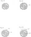
- Fig. 1is a plan view of a warp-knitted jersey according to ISO 8388 3.5.1.
- the fabriccan be used as the basis for producing a flexible grinding product.
- the clothis provided with a coating and it is flattened such that a sine-type plateau-structure 100 is generated as shown in Fig. 2 ..
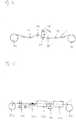
- Figs. 9 and 10schematically illustrate a tool and process for applying a coating to the grinding surface of the cloth and for flattening the surface.
- Fig. 9shows a processing line having a number of drums 10, 20, 21, 30, 31, some of them are optional, for transporting and processing a flexible grinding product and one or more UV-radiation sources 40.
- Drum 30is for unwinding the pre-processed flexible grinding product, and drum 31 is for winding the prepared product.
- Smoothing drum 10is illustrated in Fig. 10 in more detail.
- the smoothing drum 10is arranged such that it gets into contact with a piece or sheet of cloth C such as illustrated in Figs. 1 and 3 .
- Press plates 11press the cloth C against a working surface of the smoothing drum 10.
- Application of the coatingis for instance performed either via the smoothing drum 10 itself or, as illustrated in Fig. 9 , via a coating drum 20 which is directly or indirectly in contact with a reservoir of coating agent 22.
- coating drum 20is in contact with another drum 21 dipped into the reservoir coating agent 22.
- Transporting drums 30, 31 and/or other devices for transporting the sheet of cloth Care provided as required.
- the smoothing drum 10serves for flattening the coated cloth C.
- the resultis a coated but still open cloth C having flat portions as for instance illustrated in Figs. 2 and 4 .
- the coatingis cured via UV-radiation originating from the UV-light source 40.
- a second UV-light source 41can be provided, or more, in case curing in more than one stages is required or desired.
- curing via heat or coolingis as well conceivable. It is as well possible to place one or more UV-light sources on the smoothed side of the cloth.
- the smoothing drum 10 or optionally drum 20 or one ore more additional drumsmay be provided with a structured pattern.
- the surface of the clothis pressed against the working surface of the drum with a desired surface structure, thereby generating a regular or irregular structure of plateaus or islands of flat surfaces.
- Fig 11shows a process with a drying- or pre cure unit 50 used for resins that are water- or solvent based.
- unit 50may be an pre cure unit when the smoothing and resin need to be pre cured or thickened before the smoothing.
- Fig 12shows a process where a heat set, water or solvent based resin is used for the smoothing.
- Drum 10'is heated and the coated cloth and its surface is heat set against the surface of the drum having the desired pattern or smoothness.
- Fig. 13shows a process including a curing unit 60 which is located between smoothing drum 10 and drum 31 for winding the flexible grinding product.
- Fig. 14illustrates a sub-process concentrating on an optional sanding process which can be included in one or more of the above described processes.
- Unwinding and winding rollers 130 and 131are optional and may be omitted when incorporating the sanding process in one of the above described processes.
- Support rollers 132 to 135serve for adjusting the flexible grinding product relative to the sanding unit which includes a sanding belt 139, an idle roller 138, a drive roller 136 and a pressure roller 137.
- two 134 and 135 of the support rollersmay be movable as illustrated in order to adjust the angle of enlacement of the grinding product C.
- Other rollersmay as well be movable, for instance for adjusting the enlacement pressure.
- the described grinding processmay be included immediately after the curing unit illustrated in Fig. 13 .
- Fig. 15illustrates a sub-process concentrating on a possible mineral coating process which may fully or partially be included in one or more of the above described processes. Unwinding and winding rollers 230 and 231 are optional and may be omitted when incorporating the mineral coating process in one of the above described processes.
- Fig. 15schematically illustrates a kiss roller coating unit 231 for make coat, an electrostatic mineral coating unit 232, a first drying or curing chamber 233, another kiss roller coating unit 234 for size coat and a second drying or curing chamber 235.
- the basic clothis based on a warp-knitted mesh fabric according to ISO 8388 3.5.46 as shown in Fig. 3 .
- the open clothis regularly flattened. The plateaus follow the shape of the filet openings of the cloth.
- Fig. 5Ashows a cross section of a loop bundle in a wale included in the cloth, such as a wale bundle or a double warp thread.
- the threadis provided with a coating 102 partially or completely filling the thread.
- the threadis filled and overcoated with coating agent 102, thereby supporting manipulation of the shape of the thread in view of generating flattened portions.
- Reference sign 102'denotes the overcoated portion of the coating 102.
- the overcoated portions 102'are flattened or smoothed in Figs. 5D , 5E and 5F .
- FIG. 5Dthe flattened portion is narrowed, a flattened and broadened example is shown in Fig. 5E .
- a smoothed and sanded coated threadis shown in Fig. 5F .
- Overcoating of the threadis not necessarily required for flattening. Instead, the filled thread as shown in Fig. 5B may as well be flattened via a smoothing drum or sanded as shown in Figs. 5G and 5H .
- the small and big circles in the illustrated loop bundlesschematically indicate that it is possible to have fibers of different cross section. As an example, four monofilaments of larger cross section are included, which can be used to form projecting loops and/or threads situated on the surface opposite to the grinding surface.
- the projecting loops and/or threadsmay serve as fastening means for mounting and holding the grinding product to a grinding tool.
- the loops and/or threadsmay serve as one part of a hook-and-loop fastener.
- the flexible grinding producthas loops 105 on the surface opposite to the grinding surface carrying the coating 102 and the plateaus 100.
- the grinding product and a supporting surface of a grinding toolwhich is not shown, are attached to each other by means of the loops 105 and corresponding means of the supporting surface, such as hooks.
- the loops and/or hooksprovide for a distance between the grinding product and the supporting surface of the tool. Grinding dust which is first transported through the open areas/meshes of the cloth is, thus, easily removed from the grinding product via the open attachment structure utilizing loops 105.
- the flexible grinding productis laminated with foam and/or velour onto a respective surface of the tool, and, alternatively, the foam may further be laminated with a velour on the opposite side for fastening.
- a belt sandercan be used, a drum sander, an oscillating sanding beam, combinations thereof or one or more other suitable sanding units.
- a calibrating roller or flat pad nip or the clothcan be pressed against the sanding unit by the actual web tension and certain angle of enlacement.
- combinations thereofmay be used combinations thereof.
- Fig. 6is a plan view of a knitted fabric which was impregnated, overcoated, sanded and thereafter selectively provided with horizontal stripes of polymer, thereby a pattern of plateaus or protruding flat areas 100 was generated. These plateaus 100 are provided with grinding particles after curing the product such that wale-portions 101 remain free of grinding particles. Thus, islands of flattened portions carrying grinding particles are achieved. The grinding islands will naturally be arbitrarily or randomly positioned on the wales as the separation of the islands do not necessarily coincide with the pattern of the fabric. This effect can be enhanced by optimizing the pitch of the smoothing pattern in relation to the pattern of the cloth.
- the pattern of plateauscan be achieved via different methods.
- the smoothing drummay carry a corresponding pattern, which then is transferred onto the surface of the fabric.
- the surfacecan be coated in an additional step with an engraved drum or roller, for instance with grooves in horizontal directions.
- the illustrated plateaus 100may as well be created with a screen-print-device.
- the coated, flattened and/or sanded surface of the clothmay be provided with an adhesive agent or make coat.
- the applied make coatmay be structured via an engraved drum.
- a screen-print-devicemay be used for applying the make coat.
- the difference of level between the plateaus and the depressions when applying the fourth alternativeis smaller than what is achievable via the first, second or third alternative because the amount of make coat is limited by abrasive coating demands.
- the coating of the grinding particlescan be made in different ways, the coating can comprise a separate make coat that bonds the separately coated grinding particles.
- the coatingcan alternatively comprise a slurry of bonding agent and grinding particles and this slurry can be coated into a layer as such, but the layer may subsequently be formed to sanding formations on the flattened surfaces in a desired pattern and shape of formations.
- the slurrymay also be transferred by a roller, belt or film with the engraved desired pattern and may further be formed and cured while in contact with the transferring element.
- FIG. 7A cross section through line C-C in Fig. 6 is shown in Fig. 7 .
- Engraved stripes separating the plateaus 100are cut roughly horizontally.
- a sloped cutting or other cuttingsmay as well be possible.
- a zig-zag-shape or sine-shape as illustrated in Fig. 6is not necessarily required.
- the shape of the flattened areas and/or the engraved patternis adjustable in view of the used fabric, the intended grinding result or other requirements.
- Figs. 8A to 8Dare cross sections including the plateaus 100 of Figs. 6 and 7 as well as an underlying coated thread or wale part.
- the wale partis provided with a coating 102.
- Overcoated portions 102'are flattened or smoothed.
- plateau 100is provided with an abrasive mineral serving as a grinding agent 103.
- Abrasive mineral 103is applied utilizing an adhesive layer 102''.
- the grinding agent 103'is a slurry deposited in even or structured formations on the flat portion 100.
- the coatingmay be based on standard Oligomer and monomer-based acrylic formulations, water-dilutable acrylates, dual cure formulations, as well as Polyurethane-dispersions or similar materials. Further, also UV-curable epoxides and vinylmonomers are suitable materials. However acrylic oligomer/monomer-based formulations are preferred.
- a formulationcan consist of 20wt% Bisphenol A Epoxy diacrylate, 5wt% (1,6)-Hexanedioldiacrylate, 15wt% Tricyclodecanedimethanol Diacrylate, 60wt% Trimethylolpropane Triacrylate.
- some of the reactive thinners or monomersmay as well partially be substituted by low viscous oligomer types such as aliphatic epoxy acrylates, e.g. CN152 from Sartomer.
- Alternative monomersmay include materials such as 2(2-ethoxyethoxy) ethyl acrylate, Isobornyl acrylate, Tetrahydrofurfuryl acrylate, 2-Phenoxyethyl acrylate, (1,6)-Hexanedioldiacrylate, Tripropylene glycol diacrylate, Dipropylene glycol diacrylate, Pentaerythritol Tetraacrylate, Di-Pentaerythritol Pentaacrylate, as well as other acrylate or methacrylate monomers.
- Suitable materialscan also be for example other radically polymerizable vinylmonomers, like N-vinylcaprolactam.
- the amount and type of filler that is used in the coatingstrongly influences on the final performance of the cured material.
- different kind of fillerscan be used whereas also various combinations of filler materials may be applied.
- UV-curable coating formulationsone needs to assure that the filler is sufficiently penetrable for UV-light in order to ensure curing of the formulation. If, however, EB post-curing is applied during or after the coating step, the filler may also be impenetrable to UV-light. In this case UV-curing is applied in order to preliminary cure the material and fix surface shape and structure whereas the full mechanical properties are reached after EB-post-curing.
- fillers powders having small particle sizes below 10pmare preferred. However coarser particles may be used as well, if applicable. Fillers may as well be used as blends in order to fine-tune the mechanical parameters of the coating. Examples for suitable fillers are Talc which is the preferred filler for this coating or Aluminumtrihydroxide as an example of an UV-penetrable filler material. Further on Kaolin, Calcium sulfate or fillers which are similar or identical to abrasive particles based on aluminumoxide, siliconcarbide and the like may be used. With increasing hardness of the filler material the coating will typically show a more brittle behavior towards tear and strain.
- the initiator system used in the formulationis dependent on the resin system that is used. For a typical radically curing acrylic formulation mixtures of several initiators may be used, depending on the type of UV-lamp, line speed and if EB-postcuring is applied.
- Benzophenone 1-hydroxy-cyclohexylphenyl-ketone mixture(Additol BCPK from Cytec) in combination with an amine acrylate (7wt%) (Ebecryl 7100) or an amine synergist for instance a tertiary amine (Ebecryl P116) may be used.
- Other initiators and combinationse.g. MAPO, BAPO, thioxanthones and combinations thereof may be more suitable in some cases, for example when good through cure is required, typically in combination with only UV-curing hardening.
- initiator types and combinationssuch as Iodonium-, Sulphonium and other derivates and e.g. anthracence-based derivates of sensitizers or the like may be applicable in case of acid-catalyzed hardening systems or if e.g. UV-LED curing is applied.
- Blending of the resinsrequires no special attention except to assure that all components are homogenously blended within the mixture.
- the UV-resinmay be blended first and the filler is added to the resin, though also the opposite order can be applied.
- the UV-curing resin formulation with filleris blended as previously described. Initiators are required in case UV-curing is applied as a curing method.
- Coating thickness of the resin blendhereby depends on the thickness of the cloth that shall be coated.
- coating thicknesses for the coating on the film substrateare between 50 and 800pm, more preferably a thicknesses of approximately 300 ⁇ m is provided.
- the film which is coated with the uncured resin mixtureis bent around a roller of suitable size and pressed against the cloth.
- the coated clothis then moved under a UV-radiation source and cured, preferably from the backside of the cloth. It is possible to provide an even or calendered film with a surface pattern to be transferred into the grinding surface of the product.
Landscapes
- Engineering & Computer Science (AREA)
- Mechanical Engineering (AREA)
- Manufacturing & Machinery (AREA)
- Textile Engineering (AREA)
- Polishing Bodies And Polishing Tools (AREA)
- Treatments For Attaching Organic Compounds To Fibrous Goods (AREA)
- Laminated Bodies (AREA)
Description
- The present invention relates to a method of manufacturing a flexible grinding product and a flexible grinding product produced by the method.
- Conventional flexible grinding products have a layer of paper, plastic or fabric carrying abrasive particles such as aluminum oxide or silicon carbide. The grinding or abrasive particles are applied to one surface of the product utilizing a binding agent. The flexible grinding product is for instance suitable to be mounted onto a rotating or oscillating plate of a grinding machine.
- One reason for deterioration of the grinding performance is due to blocking as abrasive dust tends to clog the grinding surface of the product.
- An improvement of the durability of the grinding product by reducing the above clogging effect was achieved with a grinding product described in
EP 0 779 851 A1 . The grinding product comprises a cloth of woven or knitted fabric having projecting loops or thread parts. A grinding agent is applied as separate agglomerates to the surface of the grinding product. The expression "separate agglomerate" means that the grinding product does not comprise a continuous grinding or binding agent layer that would cover the surface of the cloth, but instead the grinding agent forms small point or line shaped accumulations. Thus the cloth has and maintains an open structure which allows to remove the grinding dust from the surface. - In the above-mentioned prior art, the grinding agent is applied onto the irregular surface of projecting threads or loops. This has the consequence that a non-uniform grinding result due to an irregular height-distribution of the grinding particles cannot be excluded, at least in critical applications. A very flexible impregnation and coating alleviates the surface failures but reduces the performance of the grinding product.
- Further, it is difficult to calibrate the product using the back surface as a support in order to achieve a flattened or smooth grinding surface. This is particularly the case when the back surface of the cloth is irregular, possibly carrying threads or loops for attaching the grinding product to a grinding tool, and/or when the back surface is at least partly fixed by an impregnation.
US 2011/0159794 A1 discloses an abrasive article including a fabric comprising a front face and a back face, wherein the abrasive article includes abrasive grains adhered to the front face of the fabric.- An object of the invention is to provide a grinding product and a method for manufacturing the same with improved grinding performance and excellent durability.
- The object is solved with a method according to claim 1 and a flexible grinding product having the features of claim 11. The dependent claims define preferred embodiments.
- In a first step, an open cloth of knitted or woven fabric is prepared. Preferred fabrics forming the basis of the grinding product are defined in ISO 8388 and comprise weft-knitted jersey-based fabrics, weft-knitted double layer jersey-based fabrics, weft-knitted rib-based fabrics, weft-knitted purl-based fabrics, warp-knitted jersey-based fabrics, warp-knitted double layer jersey-based fabrics, warp-knitted rib-based fabrics, warp-knitted purl-based fabrics, combined warp- and weft-knitted jersey-based fabrics and others. Here, it is important that the cloth is a so-called "open cloth", i.e. the cloth contains open spaces or regions defined for instance by loops or meshes. The open structure of the cloth allows removing grinding dust from the surface of the grinding product. The grinding dust can, for instance, be removed via evacuation from the backside of the grinding product.
- In a second step, a coating is applied to one surface of the cloth. In the following, the surface carrying the coating is called grinding surface or front surface. The application of the coating is such that the coated surface of the cloth has one or more flat areas. In other words, the irregular grinding surface of the cloth defined by more or less protruding loops or threads etc. is not maintained unprocessed. Instead, the height-distribution is modified by the coating and/or the process of applying the coating such that one or more flat or plane areas are generated. The resulting cloth has a flattened front surface. Preferably, the coating is a polymer.
- In a third step, a grinding agent is applied to the coated surface of the cloth. If necessary, an adhesive agent is used for adhering the grinding agent to the grinding surface.
- The flexible grinding product as prepared above contains a network of channels and/or openings defined by fully or partially coated threads of the cloth. Due to the abovedefined coating, plane portions carrying grinding agent are achieved without considerably impairing the open structure of the product. Thus, even though the flexible grinding product according to the invention utilized an open cloth, wellcontrolled and uniform grinding results are achievable. Further, the open cloth provided with controlled and flattened surface portions allows for very precise coatings like low or controlled make coat levels, intricate formations deposition and different print coating methods. Moreover, a very flexible impregnation and coating with minimal tendency to surface failures with excellent performance of the grinding product is achieved.
- The above second step contains at least two sub-steps. In a first sub-step, the coating is applied to the grinding surface of the cloth. In a second sub-step, at least a part of the coated surface is flattened, for example by pressing the grinding surface against a working surface of a smoothing element, such as a plate, belt, film or drum. Large quantities of the flexible grinding product can thus be manufactured in a highly productive manner. When pressing the grinding surface against the smoothing element, a curing-step of the coating can be performed at the same time as discussed in more detail further below. Applying the coating and flattening the grinding surface via a smoothing element can be performed simultaneously or subsequently. In other words, the order of the two sub-steps of the second step is not particularly restricted. For instance, the smoothing element may carry the coating and apply the coating when pressing the grinding surface of the product against the working surface of the plate or drum. All kinds of pressure-less and low pressure coating and printing methods, such as kiss roller, gravure roller and screen printing that do not fill the openings in the cloth can be used. It is as well possible to apply the coating beforehand, for instance via dipping the cloth into the coating or spraying the coating onto the grinding surface or printing the coating onto the surface. When using a smoothing drum, large or even endless sheets of cloth can efficiently be treated.
- Preferably, the working surface of the smoothing element is provided with a structural pattern, for instance made of grooves and/or dimples for producing a pattern of plateaus in the coated surface. Printing or engraving a well-defined three-dimensional pattern into the grinding surface can be performed with regard to the uncoated cloth, the coated cloth or by simultaneously coating the cloth. It is for instance possible to press the cloth against a working surface of an engraved roller to create an engraved surface structure having protruding flat plateaus. Sometimes it is desired to have a three dimensional structure of isolated islands of flat plateaus in order to achieve a desired grinding result. In this respect, not only the coating but also the grinding agent is applied preferably discontinuously, for example in the shape of separate small islands. Further, when introducing artificial depressions or grooves into the cloth, well-defined channels are generated for evacuation of the grinding dust. In this respect, preferably, the engraved pattern is a regular or periodic pattern of grooves or depressions.
- It is preferable that the coating is applied or calendered in a soft or fluid state. The viscosity can for instance be increased with heat. In this case, the coating can easily be applied with a well-defined thickness. It is preferable that the coating does not fully penetrate the cloth. When applying a coating with a certain viscosity, it may become necessary to cure the coating. This is achieved preferably via UV-radiation or other radiation. In this case, flattening the grinding surface via a smoothing element and curing the coating or performing part of the curing process can be achieved simultaneously or almost simultaneously. It is for instance possible to press the surface of the cloth against the working surface of the smoothing element while irradiating UV-light from the opposite side. The beams penetrate the cloth and reach the coating at the interface between grinding product and drum or plate. Alternatively, cooling or heating the coating is as well possible, in case the coating includes a thermosetting or a thermoplastic material. Curing or forming via heat or cooling can efficiently be achieved via a heated or cooled drum provided behind or downstream the smoothing element. Also the heated or cooled drum may have a desired structural pattern in its surface as to be transferred to the grinding surface of the product.
- After curing, the coated surface of the cloth is preferably provided with an adhesive agent in order to support application and adhesion of the grinding agent which is to be applied. In this respect, it is preferable to apply the grinding agent or grinding particles via a kiss drum or via some other pressure-less of low-pressure method. When applying the grinding agent, it is thus preferable not to degrade the flattened, patterned structure of the grinding surface. Preferably, only flattened areas or plateaus are provided with grinding particles. The level difference between the higher plateaus and the lower depressions allows for a selective coating of only the higher plateaus. The generated grooves or channels as well as the openings of the fabric shall not be clogged with grinding particles. Preferably, the grinding particles or grinding agent contain abrasive particles such as aluminum oxide or silicon carbide, also more special particles such as diamond, boron nitride and engineered grains can be used. The flattened surface of the cloth is not only superior in view of the grinding result but also in view of the actual process of applying the grinding particles. The structured surface has plane surface elements following the knitted or woven structure of the product. The product can be provided with grinding particles in a well-defined manner.
- Preferably flattening the coated grinding surface of the cloth includes a step of sanding the surface. A sanding step may be applied to further define or to define in first place the flattened structure. Sanding the grinding surface is useful in view of adjusting the size of the flattened areas as well as whether and how the flattened islands or areas are connected with each other. Here, a belt sander can be used, a drum sander, an oscillating sanding beam, combinations thereof or one or more other suitable sanding units. There may be used a calibrating roller or flat pad nip or the cloth can be pressed against the sanding unit by the actual web tension and certain angle of enlacement. There may as well be used combinations thereof.
- Preferably, the cloth of knitted or woven fabric is impregnated before applying the coating. The impregnation helps preparing the cloth for accepting the coating. The impregnation stabilizes the structure of the fabric. Preferably, the impregnation agent is a resin (or a different)with a filler and may be based on latex to give a desired flexibility and elasticity.
- Preferably, the cloth is provided with projecting loops and/or threads situated on the surface opposite to the grinding surface, wherein the projecting loops and/or threads originate from the threads of the cloth and wherein the projecting loops and/or threads are substantially free of the coating. The projecting loops and/or threads may serve as fastening means for mounting and holding the grinding product to a grinding tool. The loops and/or threads may serve as one part of a hook-and-loop fastener. In a preferred alternative, the flexible grinding product is laminated with foam onto a respective surface of the tool and the foam may further be laminated with a velour on the opposite side for fastening. Preferably, the flexible grinding product is provided with a foam and/or a velour on the side which is intended to be fastened to a respective surface of a grinding tool.
- Preferably, the coating is or includes a polymer. The coating may be based on standard Oligomer and monomer-based acrylic formulations, water-dilutable acrylates, dual cure formulations, as well as Polyurethane-dispersions or similar materials. Further, also UV-curable epoxides and vinylmonomers are suitable materials. However acrylic oligomer/monomer-based formulations are preferred.
- In the following, a tool or machine for coating and flattening a flexible grinding product is described. The tool comprises a coating agent applying unit for applying a coating agent to the grinding surface of the cloth, a smoothing and pressing unit, wherein the smoothing and pressing unit has a smoothing drum and is constructed and arranged so that the grinding surface of the cloth is pressed against the smoothing roll for flattening at least portions of the grinding surface, and a curing unit for curing the coating. It is possible that the coating agent applying unit and the smoothing and pressing unit are realized in one single unit allowing for simultaneously applying the coating agent and flattening the cloth.
- According to one embodiment, the tool further comprises a grinding agent applying unit for applying a grinding agent to the grinding surface of the cloth.
- Preferably, the tool further comprises a radiation source for curing the coating agent. Preferably, the radiation source is positioned opposite to the smoothing drum such that the radiation penetrates the cloth and the coated cloth is smoothened and cured simultaneously.
- Preferably, the radiation for curing the coating agent is ultraviolet radiation.
- Preferably, the tool further comprises means for transporting the cloth from the coating agent applying unit to the smoothing and pressing unit, if applicable, and for transporting the layer of knitted fabric from the smoothing and pressing unit to the grinding agent applying unit, if applicable.
- Further advantages and aspects of the present invention are provided in the following description of particular embodiments. The above and below described features may be taken alone but may as well be taken in combination as long as they do not contradict each other. The following description has to be taken in consideration of the enclosed figures. In the figures, similar features carry the same reference sign.
Fig. 1 is a plan view of a cloth of knitted fabric.Fig. 2 is a plan view of the cloth according toFig. 1 , which has been coated and flattened.Fig. 3 is a plan view of a knitted fabric different to the fabric shown inFig. 1 .Fig. 4 is a plan view of the fabric shown inFig. 3 , which has been coated and flattened.Figs. 5A to 5H show cross sections of exemplary raw, coated and modified threads of a cloth.Fig. 6 is a plan view of an impregnated, coated and sanded cloth.Fig. 7 shows the cross section through line C-C inFig. 6 .Figs. 8A to 8D show cross sections through line D-D ofFig. 6 .Figs. 9 to 15 schematically illustrate tools and processes for coating and flattening a cloth of fabric.Fig. 16 shows a cross section of a grinding product including loops on the surface opposite to the grinding surface.Fig. 1 is a plan view of a warp-knitted jersey according to ISO 8388 3.5.1. The fabric can be used as the basis for producing a flexible grinding product.- The cloth is provided with a coating and it is flattened such that a sine-type plateau-
structure 100 is generated as shown inFig. 2 .. Figs. 9 and 10 schematically illustrate a tool and process for applying a coating to the grinding surface of the cloth and for flattening the surface.Fig. 9 shows a processing line having a number ofdrums radiation sources 40.Drum 30 is for unwinding the pre-processed flexible grinding product, and drum 31 is for winding the prepared product.- Smoothing
drum 10 is illustrated inFig. 10 in more detail. The smoothingdrum 10 is arranged such that it gets into contact with a piece or sheet of cloth C such as illustrated inFigs. 1 and3 . Press plates 11 press the cloth C against a working surface of the smoothingdrum 10. Application of the coating is for instance performed either via the smoothingdrum 10 itself or, as illustrated inFig. 9 , via acoating drum 20 which is directly or indirectly in contact with a reservoir ofcoating agent 22. InFig. 9 ,coating drum 20 is in contact with anotherdrum 21 dipped into thereservoir coating agent 22. Transportingdrums - The smoothing
drum 10 serves for flattening the coated cloth C. The result is a coated but still open cloth C having flat portions as for instance illustrated inFigs. 2 and4 . Thereafter or at the time of pressing the cloth C against the working surface of the smoothingdrum 10, the coating is cured via UV-radiation originating from the UV-light source 40. Optionally, a second UV-light source 41 can be provided, or more, in case curing in more than one stages is required or desired. Depending on the coating agent, curing via heat or cooling is as well conceivable. It is as well possible to place one or more UV-light sources on the smoothed side of the cloth. - In order to achieve a zig-zag-pattern or sine-pattern as shown in
Fig. 2 , the smoothingdrum 10 or optionally drum 20 or one ore more additional drums may be provided with a structured pattern. The surface of the cloth is pressed against the working surface of the drum with a desired surface structure, thereby generating a regular or irregular structure of plateaus or islands of flat surfaces. - Alternative tools and processes for applying a coating to the grinding surface of the cloth and for flattening the surface are shown in
Figs. 11 to 15 . Fig 11 shows a process with a drying- orpre cure unit 50 used for resins that are water- or solvent based. Alternatively,unit 50 may be an pre cure unit when the smoothing and resin need to be pre cured or thickened before the smoothing.Fig 12 shows a process where a heat set, water or solvent based resin is used for the smoothing. Drum 10' is heated and the coated cloth and its surface is heat set against the surface of the drum having the desired pattern or smoothness.Fig. 13 shows a process including acuring unit 60 which is located between smoothingdrum 10 and drum 31 for winding the flexible grinding product.- For simplicity,
Fig. 14 illustrates a sub-process concentrating on an optional sanding process which can be included in one or more of the above described processes. Unwinding and windingrollers Support rollers 132 to 135 serve for adjusting the flexible grinding product relative to the sanding unit which includes a sanding belt 139, anidle roller 138, adrive roller 136 and apressure roller 137. For instance, two 134 and 135 of the support rollers may be movable as illustrated in order to adjust the angle of enlacement of the grinding product C. Other rollers may as well be movable, for instance for adjusting the enlacement pressure. As an example, the described grinding process may be included immediately after the curing unit illustrated inFig. 13 . - For simplicity,
Fig. 15 illustrates a sub-process concentrating on a possible mineral coating process which may fully or partially be included in one or more of the above described processes. Unwinding and windingrollers Fig. 15 schematically illustrates a kissroller coating unit 231 for make coat, an electrostaticmineral coating unit 232, a first drying or curingchamber 233, another kissroller coating unit 234 for size coat and a second drying or curingchamber 235. - In another example, the basic cloth is based on a warp-knitted mesh fabric according to ISO 8388 3.5.46 as shown in
Fig. 3 . InFig. 4 , the open cloth is regularly flattened. The plateaus follow the shape of the filet openings of the cloth. Fig. 5A shows a cross section of a loop bundle in a wale included in the cloth, such as a wale bundle or a double warp thread. InFig. 5B , the thread is provided with a coating 102 partially or completely filling the thread. InFig. 5C , the thread is filled and overcoated with coating agent 102, thereby supporting manipulation of the shape of the thread in view of generating flattened portions. Reference sign 102' denotes the overcoated portion of the coating 102. For example, the overcoated portions 102' are flattened or smoothed inFigs. 5D ,5E and 5F . Wherein inFig. 5D the flattened portion is narrowed, a flattened and broadened example is shown inFig. 5E . A smoothed and sanded coated thread is shown inFig. 5F . Overcoating of the thread is not necessarily required for flattening. Instead, the filled thread as shown inFig. 5B may as well be flattened via a smoothing drum or sanded as shown inFigs. 5G and 5H . The small and big circles in the illustrated loop bundles schematically indicate that it is possible to have fibers of different cross section. As an example, four monofilaments of larger cross section are included, which can be used to form projecting loops and/or threads situated on the surface opposite to the grinding surface. The projecting loops and/or threads may serve as fastening means for mounting and holding the grinding product to a grinding tool. The loops and/or threads may serve as one part of a hook-and-loop fastener.- An embodiment illustrating the above mentioned projecting loops is shown in
Fig. 16 . Here, the flexible grinding product hasloops 105 on the surface opposite to the grinding surface carrying the coating 102 and theplateaus 100. The grinding product and a supporting surface of a grinding tool, which is not shown, are attached to each other by means of theloops 105 and corresponding means of the supporting surface, such as hooks. The loops and/or hooks provide for a distance between the grinding product and the supporting surface of the tool. Grinding dust which is first transported through the open areas/meshes of the cloth is, thus, easily removed from the grinding product via the open attachmentstructure utilizing loops 105. Alternatively or additionally, the flexible grinding product is laminated with foam and/or velour onto a respective surface of the tool, and, alternatively, the foam may further be laminated with a velour on the opposite side for fastening. - For sanding the product, a belt sander can be used, a drum sander, an oscillating sanding beam, combinations thereof or one or more other suitable sanding units. There may be used a calibrating roller or flat pad nip or the cloth can be pressed against the sanding unit by the actual web tension and certain angle of enlacement. There may as well be used combinations thereof.
Fig. 6 is a plan view of a knitted fabric which was impregnated, overcoated, sanded and thereafter selectively provided with horizontal stripes of polymer, thereby a pattern of plateaus or protrudingflat areas 100 was generated. These plateaus 100 are provided with grinding particles after curing the product such that wale-portions 101 remain free of grinding particles. Thus, islands of flattened portions carrying grinding particles are achieved. The grinding islands will naturally be arbitrarily or randomly positioned on the wales as the separation of the islands do not necessarily coincide with the pattern of the fabric. This effect can be enhanced by optimizing the pitch of the smoothing pattern in relation to the pattern of the cloth.- The pattern of plateaus can be achieved via different methods. For instance, the smoothing drum may carry a corresponding pattern, which then is transferred onto the surface of the fabric. Alternatively, after sanding or flattening the grinding surface of the cloth, the surface can be coated in an additional step with an engraved drum or roller, for instance with grooves in horizontal directions. As a third alternative, the illustrated
plateaus 100 may as well be created with a screen-print-device. According to a fourth alternative, the coated, flattened and/or sanded surface of the cloth may be provided with an adhesive agent or make coat. The applied make coat may be structured via an engraved drum. Alternatively, a screen-print-device may be used for applying the make coat. Typically, the difference of level between the plateaus and the depressions when applying the fourth alternative is smaller than what is achievable via the first, second or third alternative because the amount of make coat is limited by abrasive coating demands. - The coating of the grinding particles can be made in different ways, the coating can comprise a separate make coat that bonds the separately coated grinding particles. The coating can alternatively comprise a slurry of bonding agent and grinding particles and this slurry can be coated into a layer as such, but the layer may subsequently be formed to sanding formations on the flattened surfaces in a desired pattern and shape of formations. The slurry may also be transferred by a roller, belt or film with the engraved desired pattern and may further be formed and cured while in contact with the transferring element.
- A cross section through line C-C in
Fig. 6 is shown inFig. 7 . Engraved stripes separating theplateaus 100 are cut roughly horizontally. A sloped cutting or other cuttings may as well be possible. Further, a zig-zag-shape or sine-shape as illustrated inFig. 6 is not necessarily required. The shape of the flattened areas and/or the engraved pattern is adjustable in view of the used fabric, the intended grinding result or other requirements. Figs. 8A to 8D are cross sections including theplateaus 100 ofFigs. 6 and7 as well as an underlying coated thread or wale part. The wale part is provided with a coating 102.- Overcoated portions 102' are flattened or smoothed. In
Fig. 8B ,plateau 100 is provided with an abrasive mineral serving as a grindingagent 103.Abrasive mineral 103 is applied utilizing an adhesive layer 102''. InFigs. 8C and 8D , the grinding agent 103' is a slurry deposited in even or structured formations on theflat portion 100. - Turning to the composition of the coating, polymers are preferred. The coating may be based on standard Oligomer and monomer-based acrylic formulations, water-dilutable acrylates, dual cure formulations, as well as Polyurethane-dispersions or similar materials. Further, also UV-curable epoxides and vinylmonomers are suitable materials. However acrylic oligomer/monomer-based formulations are preferred.
- As an example, a formulation can consist of 20wt% Bisphenol A Epoxy diacrylate, 5wt% (1,6)-Hexanedioldiacrylate, 15wt% Tricyclodecanedimethanol Diacrylate, 60wt% Trimethylolpropane Triacrylate.
- As alternatives also other combinations may be used which include other types of Epoxy acrylates, Polyester, Melamin, Polyurethane or Polyether acrylates.
- To achieve suitable viscosity ranges some of the reactive thinners or monomers may as well partially be substituted by low viscous oligomer types such as aliphatic epoxy acrylates, e.g. CN152 from Sartomer.
- Alternative monomers may include materials such as 2(2-ethoxyethoxy) ethyl acrylate, Isobornyl acrylate, Tetrahydrofurfuryl acrylate, 2-Phenoxyethyl acrylate, (1,6)-Hexanedioldiacrylate, Tripropylene glycol diacrylate, Dipropylene glycol diacrylate, Pentaerythritol Tetraacrylate, Di-Pentaerythritol Pentaacrylate, as well as other acrylate or methacrylate monomers. Suitable materials can also be for example other radically polymerizable vinylmonomers, like N-vinylcaprolactam.
- The amount and type of filler that is used in the coating strongly influences on the final performance of the cured material. In order to modify the properties of the coating different kind of fillers can be used whereas also various combinations of filler materials may be applied. In case of UV-curable coating formulations one needs to assure that the filler is sufficiently penetrable for UV-light in order to ensure curing of the formulation. If, however, EB post-curing is applied during or after the coating step, the filler may also be impenetrable to UV-light. In this case UV-curing is applied in order to preliminary cure the material and fix surface shape and structure whereas the full mechanical properties are reached after EB-post-curing.
- For fillers powders having small particle sizes below 10pm are preferred. However coarser particles may be used as well, if applicable. Fillers may as well be used as blends in order to fine-tune the mechanical parameters of the coating. Examples for suitable fillers are Talc which is the preferred filler for this coating or Aluminumtrihydroxide as an example of an UV-penetrable filler material. Further on Kaolin, Calcium sulfate or fillers which are similar or identical to abrasive particles based on aluminumoxide, siliconcarbide and the like may be used. With increasing hardness of the filler material the coating will typically show a more brittle behavior towards tear and strain.
- The initiator system used in the formulation is dependent on the resin system that is used. For a typical radically curing acrylic formulation mixtures of several initiators may be used, depending on the type of UV-lamp, line speed and if EB-postcuring is applied.
- For a typical formulation with UV pre-curing and EB post-curing e.g. 5wt% Benzophenone 1-hydroxy-cyclohexylphenyl-ketone mixture (Additol BCPK from Cytec) in combination with an amine acrylate (7wt%) (Ebecryl 7100) or an amine synergist for instance a tertiary amine (Ebecryl P116) may be used. Other initiators and combinations e.g. MAPO, BAPO, thioxanthones and combinations thereof may be more suitable in some cases, for example when good through cure is required, typically in combination with only UV-curing hardening.
- Other initiator types and combinations such as Iodonium-, Sulphonium and other derivates and e.g. anthracence-based derivates of sensitizers or the like may be applicable in case of acid-catalyzed hardening systems or if e.g. UV-LED curing is applied.
- Blending of the resins requires no special attention except to assure that all components are homogenously blended within the mixture. Depending on the mixing equipment, the UV-resin may be blended first and the filler is added to the resin, though also the opposite order can be applied.
- The choice of the type of monomer, oligomer and filler combination as well as their ratios strongly depend on the mechanical properties which are required or desired during the further process, e.g. as to the treatment the material such as winding or cutting. Mechanically, the coating needs to be capable of achieving sufficient tension and tear resistance as well as a sufficient flexibility for handling the material during the process.
- In terms of applying the coating to a cloth, the UV-curing resin formulation with filler is blended as previously described. Initiators are required in case UV-curing is applied as a curing method.
- According to one embodiment, it has shown to be practical to spread the resin/filler mixture by using a doctor roller on an even plastic film substrate, e.g. a PET film. Coating thickness of the resin blend hereby depends on the thickness of the cloth that shall be coated. Preferably coating thicknesses for the coating on the film substrate are between 50 and 800pm, more preferably a thicknesses of approximately 300µm is provided. Subsequently, the film which is coated with the uncured resin mixture is bent around a roller of suitable size and pressed against the cloth. The coated cloth is then moved under a UV-radiation source and cured, preferably from the backside of the cloth. It is possible to provide an even or calendered film with a surface pattern to be transferred into the grinding surface of the product.
Claims (15)
- A method of manufacturing a flexible grinding product, the method comprising the following steps:a) preparing an open cloth (C) of knitted or woven fabric;b) applying a coating (102) to one surface of the cloth (C), wherein the coated surface of the cloth (C) has one or more flat plateaus (100);c) applying a grinding agent (103) to the coated surface of the cloth (C),wherein step b) includes:b1) applying the coating (102) to one surface of the cloth (C);b2) flattening at least part of the coated surface,wherein step b2) includes pressing the surface against a working surface of a smoothing element (10), the working surface of the smoothing element (10) preferably being provided with a structural pattern for producing a pattern of plateaus in the coated surface,
and/or
step b2) comprises sanding the coated surface for producing one or more flat plateaus (100). - Method according to claim 1,characterized in that the coating (102) is applied discontinuously in shape of separated small islands, and / orin that the coating (102) is cured after step b), preferably with UV-radiation or heat.
- Method according to any one of the preceding claims,characterized in that the cloth (C) is impregnated between steps a) and b).
- Method according to any one of the preceding claims,characterized in that the cloth (C) is provided with projecting loops and/or threads situated on the opposite surface of the surface to be coated, the loops and/or threads originating from threads of the cloth (C), wherein
the coating (102) is applied and cured such that the projecting loops and/or threads are substantially free of the coating. - Method according to any one of the preceding claims,characterized in that the coating (102) includes a polymer.
- Method according to any one of the preceding claims,characterized in that the smoothing element (10) is a smoothing drum.
- Method according to any one of the preceding claims,characterized in that the grinding agent (103) is a slurry deposited into sanding formations on the flat plateaus (100) of the cloth.
- Method according to any one of the preceding claims,characterized in that the flexible grinding product is laminated with a foam onto a respective surface of a grinding tool.
- Method according to any one of the preceding claims,characterized in that the flexible grinding product is laminated with a velour onto a respective surface of a grinding tool.
- Flexible grinding product having an open cloth (C), wherein a surface of the cloth (C) is provided with a coating (102) such that the coated surface has one or more flat plateaus which are at least partially provided with a grinding agent (103),characterized in that, before application of the grinding agent, at least part of the coated surface has been flattened by pressing the surface against a working surface of a smoothing element (10) for producing the one or more flat plateaus (100)
and/or
the coated surface has been sanded for producing the one or more flat plateaus (100). - Flexible grinding product according to claim 10,characterized in that the coated surface of the cloth (C) has a pattern of grooves or an engraved structure including protruding flat plateaus (100), and / orin that the coating (102) is applied discontinuously in the shape of separate small islands.
- Flexible grinding product according to any one of claims 10 to 11,characterized in that the cloth (C) is impregnated.
- Flexible grinding product according to any one of claims 10 to 12,characterized in that the cloth (C) is provided with projecting loops and/or threads situated on the opposite surface of the surface to be coated, the projecting loops and/or threads originating from threads of the cloth (C), wherein the projecting loops and/or threads are substantially free of the coating.
- Flexible grinding product according to any one of claims 10 to 13,characterized in that the grinding agent (103) is a slurry that is deposited as sanding formations on the flattened surfaces (100) of the cloth.
- Flexible grinding product according to any one of claims 10 to 14,characterized in that the flexible grinding product is laminated with a foam onto a respective surface of a grinding tool, and / orin that the flexible grinding product is laminated with a velour onto a respective surface of a grinding tool.
Priority Applications (2)
| Application Number | Priority Date | Filing Date | Title |
|---|---|---|---|
| PL12756703TPL2895298T3 (en) | 2012-09-05 | 2012-09-05 | Flexible grinding product with flattened surface and method for manufacturing the same |
| EP21203123.1AEP4000807A1 (en) | 2012-09-05 | 2012-09-05 | Flexible grinding product with flattened surface and method for manufacturing the same |
Applications Claiming Priority (1)
| Application Number | Priority Date | Filing Date | Title |
|---|---|---|---|
| PCT/EP2012/067294WO2014037034A1 (en) | 2012-09-05 | 2012-09-05 | Flexible grinding product with flattened surface and method for manufacturing the same |
Related Child Applications (1)
| Application Number | Title | Priority Date | Filing Date |
|---|---|---|---|
| EP21203123.1ADivisionEP4000807A1 (en) | 2012-09-05 | 2012-09-05 | Flexible grinding product with flattened surface and method for manufacturing the same |
Publications (2)
| Publication Number | Publication Date |
|---|---|
| EP2895298A1 EP2895298A1 (en) | 2015-07-22 |
| EP2895298B1true EP2895298B1 (en) | 2021-10-20 |
Family
ID=46829740
Family Applications (2)
| Application Number | Title | Priority Date | Filing Date |
|---|---|---|---|
| EP12756703.0AActiveEP2895298B1 (en) | 2012-09-05 | 2012-09-05 | Flexible grinding product with flattened surface and method for manufacturing the same |
| EP21203123.1APendingEP4000807A1 (en) | 2012-09-05 | 2012-09-05 | Flexible grinding product with flattened surface and method for manufacturing the same |
Family Applications After (1)
| Application Number | Title | Priority Date | Filing Date |
|---|---|---|---|
| EP21203123.1APendingEP4000807A1 (en) | 2012-09-05 | 2012-09-05 | Flexible grinding product with flattened surface and method for manufacturing the same |
Country Status (14)
| Country | Link |
|---|---|
| US (1) | US10549403B2 (en) |
| EP (2) | EP2895298B1 (en) |
| JP (1) | JP2015527212A (en) |
| KR (1) | KR101991417B1 (en) |
| CN (2) | CN104797380A (en) |
| AU (1) | AU2012389284B2 (en) |
| CA (2) | CA2883790C (en) |
| ES (1) | ES2902993T3 (en) |
| MX (1) | MX389155B (en) |
| PL (1) | PL2895298T3 (en) |
| RU (1) | RU2617184C2 (en) |
| TW (1) | TWI669192B (en) |
| WO (1) | WO2014037034A1 (en) |
| ZA (1) | ZA201501495B (en) |
Families Citing this family (18)
| Publication number | Priority date | Publication date | Assignee | Title |
|---|---|---|---|---|
| EP2895298B1 (en) | 2012-09-05 | 2021-10-20 | Mirka Oy | Flexible grinding product with flattened surface and method for manufacturing the same |
| US20160059388A1 (en)* | 2014-08-26 | 2016-03-03 | Scott Pray | Sanding cloths |
| USD807045S1 (en) | 2015-05-08 | 2018-01-09 | Mirka Oy | Abrasive material |
| DE202015009577U1 (en) | 2015-05-08 | 2018-06-28 | Mirka Ltd. | Abrasive belt grinding product |
| DE202015103867U1 (en) | 2015-05-08 | 2016-08-10 | Kwh Mirka Ltd. | Abrasive belt / Abrasive Product |
| TWI765851B (en)* | 2015-05-08 | 2022-06-01 | 芬蘭商磨卡公司 | Abrasive belt grinding product |
| AU2015394604B2 (en)* | 2015-05-08 | 2019-08-01 | Mirka Ltd. | Abrasive belt grinding product |
| US11407087B2 (en) | 2016-04-04 | 2022-08-09 | Mirka Ltd. | Abrasive product |
| WO2018018821A1 (en)* | 2016-07-25 | 2018-02-01 | 江苏锋芒复合材料科技集团有限公司 | Coated abrasive net, and manufacturing method thereof |
| TWI587981B (en)* | 2016-09-02 | 2017-06-21 | Mesh emery cloth with open holes | |
| USD846213S1 (en)* | 2017-06-19 | 2019-04-16 | The Procter & Gamble Company | Cleaning pad |
| USD844271S1 (en)* | 2017-07-14 | 2019-03-26 | Fusionbrands Llc | Wave sponge |
| WO2019111212A1 (en) | 2017-12-08 | 2019-06-13 | 3M Innovative Properties Company | Porous abrasive article |
| EP3924150A1 (en) | 2019-02-11 | 2021-12-22 | 3M Innovative Properties Company | Abrasive article |
| CN111015537A (en)* | 2019-12-20 | 2020-04-17 | 贲庆飞 | Production process of abrasive cloth switching abrasive belt double-sided traceless interface |
| CN113386058A (en)* | 2020-03-12 | 2021-09-14 | 凯吉斯金刚石(广州)有限公司 | Abrasive article and method of making such article |
| GB202008685D0 (en) | 2020-06-09 | 2020-07-22 | Mirka Oy | Abrasive product and method for manufacturing abrasive product |
| FI130281B (en) | 2021-11-25 | 2023-06-01 | Mirka Oy | Abrasive product |
Family Cites Families (78)
| Publication number | Priority date | Publication date | Assignee | Title |
|---|---|---|---|---|
| US1561727A (en) | 1924-05-16 | 1925-11-17 | Metal Textile Corp | Abrasive fabric |
| GB434186A (en)* | 1935-02-22 | 1935-08-22 | Carborundum Co | Improvements in or relating to flexible abrasive coated articles and the manufacturethereof |
| US2740239A (en)* | 1953-07-02 | 1956-04-03 | Bay State Abrasive Products Co | Flexible abrasive products |
| US2778169A (en)* | 1953-10-20 | 1957-01-22 | Bay State Abrasive Products Co | Flexible abrasive bands |
| US2984052A (en)* | 1959-08-12 | 1961-05-16 | Norton Co | Coated abrasives |
| US3276852A (en) | 1962-11-20 | 1966-10-04 | Jerome H Lemelson | Filament-reinforced composite abrasive articles |
| JPS5011118A (en) | 1973-05-28 | 1975-02-05 | ||
| US4227350A (en)* | 1977-11-02 | 1980-10-14 | Minnesota Mining And Manufacturing Company | Low-density abrasive product and method of making the same |
| DE2928484B1 (en)* | 1979-07-14 | 1980-10-16 | Ver Schmirgel & Maschf | Process for the production of flexible abrasives |
| US4282011A (en)* | 1980-05-30 | 1981-08-04 | Dan River Incorporated | Woven fabrics containing glass fibers and abrasive belts made from same |
| US4867760A (en)* | 1980-07-31 | 1989-09-19 | Norton Company | Coated abrasive |
| JPH0624703B2 (en) | 1985-04-23 | 1994-04-06 | 齊 山崎 | Belt-shaped grinding wheel manufacturing method |
| US4826508A (en) | 1986-09-15 | 1989-05-02 | Diabrasive International, Ltd. | Flexible abrasive coated article and method of making it |
| AU613584B2 (en)* | 1986-09-15 | 1991-08-08 | Abrasive Technology N.A. Inc. | A flexible abrasive coated article and method of making it |
| AU1215788A (en) | 1987-02-27 | 1988-09-01 | Diabrasive International Ltd. | Flexible abrasives |
| JPS63283868A (en) | 1987-02-27 | 1988-11-21 | Toshiba Tungaloy Co Ltd | Superabrasive grain boring tool |
| US4925457B1 (en)* | 1989-01-30 | 1995-09-26 | Ultimate Abrasive Syst Inc | Method for making an abrasive tool |
| GB8911312D0 (en) | 1989-05-17 | 1989-07-05 | Am Int | Multi-disc cutter and method of manufacture |
| US5203881A (en)* | 1990-02-02 | 1993-04-20 | Wiand Ronald C | Abrasive sheet and method |
| US5131924A (en)* | 1990-02-02 | 1992-07-21 | Wiand Ronald C | Abrasive sheet and method |
| CA2036247A1 (en) | 1990-03-29 | 1991-09-30 | Jeffrey L. Berger | Nonwoven surface finishing articles reinforced with a polymer backing layer and method of making same |
| US5368618A (en)* | 1992-01-22 | 1994-11-29 | Minnesota Mining And Manufacturing Company | Method of making a coated abrasive article |
| JPH06155314A (en) | 1992-11-17 | 1994-06-03 | Nippon Steel Corp | Laminating roll type grinding tool |
| US5681612A (en) | 1993-06-17 | 1997-10-28 | Minnesota Mining And Manufacturing Company | Coated abrasives and methods of preparation |
| FI96585C (en) | 1994-09-06 | 1996-07-25 | Kwh Mirka Ab Oy | sanding |
| MX9702267A (en)* | 1994-09-30 | 1997-06-28 | Minnesota Mining & Mfg | Coated abrasive article, method for preparing the same, and method of using. |
| US5674122A (en) | 1994-10-27 | 1997-10-07 | Minnesota Mining And Manufacturing Company | Abrasive articles and methods for their manufacture |
| US5679067A (en)* | 1995-04-28 | 1997-10-21 | Minnesota Mining And Manufacturing Company | Molded abrasive brush |
| US5578343A (en) | 1995-06-07 | 1996-11-26 | Norton Company | Mesh-backed abrasive products |
| DE29518953U1 (en) | 1995-11-29 | 1997-03-27 | Hermes-Schleifmittel GmbH & Co, 22547 Hamburg | Sanding belt |
| DE19727104C2 (en)* | 1997-06-26 | 2000-07-20 | Ver Schmirgel & Maschf | Flexible grinding wheel and process for its manufacture |
| US6180166B1 (en)* | 1998-07-21 | 2001-01-30 | Benny R. Wood | Double-sided adhesive material and method of making |
| US6458018B1 (en)* | 1999-04-23 | 2002-10-01 | 3M Innovative Properties Company | Abrasive article suitable for abrading glass and glass ceramic workpieces |
| US6634929B1 (en)* | 1999-04-23 | 2003-10-21 | 3M Innovative Properties Company | Method for grinding glass |
| JP2001001272A (en) | 1999-06-22 | 2001-01-09 | Kenken:Kk | Rotary tool |
| US20020090901A1 (en) | 2000-11-03 | 2002-07-11 | 3M Innovative Properties Company | Flexible abrasive product and method of making and using the same |
| US20030022604A1 (en)* | 2001-05-07 | 2003-01-30 | 3M Innovative Properties Company | Abrasive product and method of making and using the same |
| US20030207659A1 (en)* | 2000-11-03 | 2003-11-06 | 3M Innovative Properties Company | Abrasive product and method of making and using the same |
| US8062098B2 (en)* | 2000-11-17 | 2011-11-22 | Duescher Wayne O | High speed flat lapping platen |
| US7632434B2 (en)* | 2000-11-17 | 2009-12-15 | Wayne O. Duescher | Abrasive agglomerate coated raised island articles |
| EP1207015A3 (en)* | 2000-11-17 | 2003-07-30 | Keltech Engineering, Inc. | Raised island abrasive, method of use and lapping apparatus |
| US8545583B2 (en)* | 2000-11-17 | 2013-10-01 | Wayne O. Duescher | Method of forming a flexible abrasive sheet article |
| DE20111245U1 (en) | 2001-07-06 | 2001-08-30 | Huang, Ying Chih, Feng-Yuan, Taichung | Emery cloth |
| US6846232B2 (en)* | 2001-12-28 | 2005-01-25 | 3M Innovative Properties Company | Backing and abrasive product made with the backing and method of making and using the backing and abrasive product |
| US6613113B2 (en)* | 2001-12-28 | 2003-09-02 | 3M Innovative Properties Company | Abrasive product and method of making the same |
| US7044989B2 (en)* | 2002-07-26 | 2006-05-16 | 3M Innovative Properties Company | Abrasive product, method of making and using the same, and apparatus for making the same |
| US6833014B2 (en)* | 2002-07-26 | 2004-12-21 | 3M Innovative Properties Company | Abrasive product, method of making and using the same, and apparatus for making the same |
| US7297170B2 (en)* | 2002-07-26 | 2007-11-20 | 3M Innovative Properties Company | Method of using abrasive product |
| US6860912B2 (en) | 2003-02-04 | 2005-03-01 | Webb Manufacturing Corporation | Abrasive filament, abrasive articles incorporating abrasive filament and method of making abrasive filaments and abrasive articles |
| FI114902B (en) | 2003-10-06 | 2005-01-31 | Kwh Mirka Ab Oy | Abrasive product for attachment to endless belts, has base and abrasive threads placed in separate mutually parallel planes |
| CN101048259B (en)* | 2004-12-06 | 2013-03-13 | 金世博有限公司 | Grinding material and its preparation method |
| JP2006159343A (en) | 2004-12-07 | 2006-06-22 | Kovax Corp | Abrasive sheet |
| JP2006289592A (en) | 2005-04-14 | 2006-10-26 | Three M Innovative Properties Co | Sheet-like applying abrasive |
| FI121653B (en) | 2005-06-13 | 2011-02-28 | Kwh Mirka Ab Oy | Flexible abrasive product and process for manufacturing the same |
| JP4987261B2 (en) | 2005-07-13 | 2012-07-25 | 株式会社 メドレックス | Gel oral preparation |
| US7252694B2 (en) | 2005-08-05 | 2007-08-07 | 3M Innovative Properties Company | Abrasive article and methods of making same |
| US7258705B2 (en) | 2005-08-05 | 2007-08-21 | 3M Innovative Properties Company | Abrasive article and methods of making same |
| US7497768B2 (en)* | 2005-08-11 | 2009-03-03 | 3M Innovative Properties Company | Flexible abrasive article and method of making |
| US7244170B2 (en) | 2005-09-16 | 2007-07-17 | 3M Innovative Properties Co. | Abrasive article and methods of making same |
| US20070066186A1 (en)* | 2005-09-22 | 2007-03-22 | 3M Innovative Properties Company | Flexible abrasive article and methods of making and using the same |
| US7285146B2 (en) | 2005-12-28 | 2007-10-23 | 3M Innovative Properties Company | Resilient abrasive article |
| US20070243802A1 (en)* | 2006-04-14 | 2007-10-18 | Petersen John G | Laminated flexible resilient abrasive article |
| US20080160879A1 (en)* | 2006-12-31 | 2008-07-03 | 3M Innovative Properties Company | Method of abrading a zirconium-based alloy workpiece |
| US20080155904A1 (en)* | 2006-12-31 | 2008-07-03 | 3M Innovative Properties Company | Method of abrading a metal workpiece |
| US20100075578A1 (en) | 2008-09-19 | 2010-03-25 | Hung-Ke Chou | Abrasive polishing net with a stickable fiber layer |
| US20110015979A1 (en)* | 2009-07-20 | 2011-01-20 | Bart Allan Mansdorf | Methods and Systems for Awarding Discounts for Experiencing Advertising |
| US8057287B2 (en) | 2009-08-10 | 2011-11-15 | Hg Tools Co., Ltd. | Abrasive mesh for a powered grinding wheel |
| US9950408B2 (en)* | 2009-11-02 | 2018-04-24 | Diamabrush Llc | Abrasive pad |
| JP2013514901A (en)* | 2009-12-22 | 2013-05-02 | スリーエム イノベイティブ プロパティズ カンパニー | Flexible abrasive article and manufacturing method |
| FR2954723B1 (en)* | 2009-12-29 | 2012-04-20 | Saint Gobain Abrasives Inc | ABRASIVE ARTICLE COMPRISING A HOLLOW SPACE BETWEEN ITS FRONT AND REAR FACES AND METHOD OF MANUFACTURE |
| FI20105606L (en) | 2010-05-28 | 2010-11-25 | Kwh Mirka Ab Oy | Abrasive product and method for producing the same |
| DE102010036554A1 (en)* | 2010-07-21 | 2012-01-26 | Bamberger Kaliko Gmbh | Composite material for further processing into flat abrasive products and process for its production |
| JP5809429B2 (en) | 2011-03-31 | 2015-11-10 | 株式会社クラレ | Polishing pad |
| US20120322352A1 (en)* | 2011-06-20 | 2012-12-20 | 3M Innovative Properties Company | Sandpaper with laminated non-slip layer |
| JP5977606B2 (en) | 2012-07-12 | 2016-08-24 | Mipox株式会社 | Surface treatment sheet with abrasive particles for treating the surface of a workpiece |
| EP2895298B1 (en) | 2012-09-05 | 2021-10-20 | Mirka Oy | Flexible grinding product with flattened surface and method for manufacturing the same |
| JP3182351U (en) | 2013-01-08 | 2013-03-21 | 三晃製砥株式会社 | Rotating whetstone and reinforcing material for rotating whetstone |
| WO2015100034A1 (en)* | 2013-12-27 | 2015-07-02 | Saint-Gobain Abrasives, Inc. | Nonwoven abrasive articles made by friction welding |
- 2012
- 2012-09-05EPEP12756703.0Apatent/EP2895298B1/enactiveActive
- 2012-09-05JPJP2015530302Apatent/JP2015527212A/enactivePending
- 2012-09-05AUAU2012389284Apatent/AU2012389284B2/enactiveActive
- 2012-09-05CACA2883790Apatent/CA2883790C/enactiveActive
- 2012-09-05RURU2015112299Apatent/RU2617184C2/enactive
- 2012-09-05WOPCT/EP2012/067294patent/WO2014037034A1/enactiveApplication Filing
- 2012-09-05MXMX2015002909Apatent/MX389155B/enunknown
- 2012-09-05CNCN201280075666.2Apatent/CN104797380A/enactivePending
- 2012-09-05USUS14/425,766patent/US10549403B2/enactiveActive
- 2012-09-05CACA3140583Apatent/CA3140583A1/enactivePending
- 2012-09-05EPEP21203123.1Apatent/EP4000807A1/enactivePending
- 2012-09-05PLPL12756703Tpatent/PL2895298T3/enunknown
- 2012-09-05ESES12756703Tpatent/ES2902993T3/enactiveActive
- 2012-09-05KRKR1020157008374Apatent/KR101991417B1/enactiveActive
- 2012-09-05CNCN202010284023.5Apatent/CN111604823A/enactivePending
- 2013
- 2013-09-05TWTW102132062Apatent/TWI669192B/enactive
- 2015
- 2015-03-04ZAZA201501495Apatent/ZA201501495B/enunknown
Non-Patent Citations (1)
| Title |
|---|
| None* |
Also Published As
| Publication number | Publication date |
|---|---|
| AU2012389284A1 (en) | 2015-03-19 |
| CA2883790C (en) | 2022-01-18 |
| AU2012389284B2 (en) | 2017-09-28 |
| TW201420276A (en) | 2014-06-01 |
| MX2015002909A (en) | 2015-09-21 |
| MX389155B (en) | 2025-03-20 |
| US10549403B2 (en) | 2020-02-04 |
| ZA201501495B (en) | 2019-10-30 |
| RU2617184C2 (en) | 2017-04-21 |
| TWI669192B (en) | 2019-08-21 |
| ES2902993T3 (en) | 2022-03-30 |
| CA3140583A1 (en) | 2014-03-13 |
| PL2895298T3 (en) | 2022-03-07 |
| CN111604823A (en) | 2020-09-01 |
| EP4000807A1 (en) | 2022-05-25 |
| BR112015004809A8 (en) | 2018-02-06 |
| KR101991417B1 (en) | 2019-06-21 |
| EP2895298A1 (en) | 2015-07-22 |
| KR20150052200A (en) | 2015-05-13 |
| CN104797380A (en) | 2015-07-22 |
| BR112015004809A2 (en) | 2017-07-04 |
| US20150343605A1 (en) | 2015-12-03 |
| CA2883790A1 (en) | 2014-03-13 |
| RU2015112299A (en) | 2016-10-27 |
| JP2015527212A (en) | 2015-09-17 |
| WO2014037034A1 (en) | 2014-03-13 |
Similar Documents
| Publication | Publication Date | Title |
|---|---|---|
| EP2895298B1 (en) | Flexible grinding product with flattened surface and method for manufacturing the same | |
| US20240253389A1 (en) | Method of manufacturing a floor board | |
| CA1186276A (en) | Resin systems for high energy electron curable resin coated webs | |
| KR102163530B1 (en) | Method for manufacturing decorative wall or floor panels | |
| CN106457524A (en) | Coated abrasive article | |
| RU2005124305A (en) | METHOD FOR MANUFACTURE OF INFINITE TAPE impregnated with RESIN, AND TAPE FOR PAPER MACHINES AND SIMILAR INDUSTRIAL USES | |
| EP0344529B1 (en) | Web with finishing coating useful as coated abrasive backing | |
| US20150174736A1 (en) | Composite Backing Material Layer And Method Of Forming Same | |
| JPH09193309A (en) | Decorative board using precoated paper | |
| US4257834A (en) | Process for producing a sheet having chip design | |
| CN108430702A (en) | Abrasive product and preparation method thereof | |
| WO2014106280A1 (en) | Abrasive articles including a blend of abrasive grains and method of forming same | |
| JP2018024092A (en) | Flexible grinding product having flattened surface and method of manufacturing the same | |
| EP3345734B1 (en) | Methods for manufacturing a reinforced fiber substrate, a shaping fabric and a fiber-reinforced plastic structure | |
| BR112015004809B1 (en) | FLEXIBLE ABRASIVE PRODUCT WITH FLAT SURFACE AND ITS MANUFACTURING METHOD | |
| JP4428606B2 (en) | Manufacturing method of decorative sheet | |
| GB2576356A (en) | Coated abrasive article and method of making the same | |
| JP4109344B2 (en) | Decorative plate manufacturing method |
Legal Events
| Date | Code | Title | Description |
|---|---|---|---|
| PUAI | Public reference made under article 153(3) epc to a published international application that has entered the european phase | Free format text:ORIGINAL CODE: 0009012 | |
| 17P | Request for examination filed | Effective date:20150325 | |
| AK | Designated contracting states | Kind code of ref document:A1 Designated state(s):AL AT BE BG CH CY CZ DE DK EE ES FI FR GB GR HR HU IE IS IT LI LT LU LV MC MK MT NL NO PL PT RO RS SE SI SK SM TR | |
| AX | Request for extension of the european patent | Extension state:BA ME | |
| DAX | Request for extension of the european patent (deleted) | ||
| RAP1 | Party data changed (applicant data changed or rights of an application transferred) | Owner name:MIRKA OY | |
| STAA | Information on the status of an ep patent application or granted ep patent | Free format text:STATUS: EXAMINATION IS IN PROGRESS | |
| 17Q | First examination report despatched | Effective date:20180215 | |
| GRAP | Despatch of communication of intention to grant a patent | Free format text:ORIGINAL CODE: EPIDOSNIGR1 | |
| STAA | Information on the status of an ep patent application or granted ep patent | Free format text:STATUS: GRANT OF PATENT IS INTENDED | |
| INTG | Intention to grant announced | Effective date:20210514 | |
| GRAS | Grant fee paid | Free format text:ORIGINAL CODE: EPIDOSNIGR3 | |
| GRAA | (expected) grant | Free format text:ORIGINAL CODE: 0009210 | |
| STAA | Information on the status of an ep patent application or granted ep patent | Free format text:STATUS: THE PATENT HAS BEEN GRANTED | |
| RIN1 | Information on inventor provided before grant (corrected) | Inventor name:GROEN, JAN Inventor name:SUNDELL, MATS Inventor name:SCHUMACHER, NICOLAS Inventor name:HEDE, HANS Inventor name:HOEGLUND, GOERAN | |
| AK | Designated contracting states | Kind code of ref document:B1 Designated state(s):AL AT BE BG CH CY CZ DE DK EE ES FI FR GB GR HR HU IE IS IT LI LT LU LV MC MK MT NL NO PL PT RO RS SE SI SK SM TR | |
| REG | Reference to a national code | Ref country code:GB Ref legal event code:FG4D | |
| REG | Reference to a national code | Ref country code:CH Ref legal event code:EP | |
| REG | Reference to a national code | Ref country code:DE Ref legal event code:R096 Ref document number:602012076956 Country of ref document:DE | |
| REG | Reference to a national code | Ref country code:IE Ref legal event code:FG4D | |
| REG | Reference to a national code | Ref country code:AT Ref legal event code:REF Ref document number:1439537 Country of ref document:AT Kind code of ref document:T Effective date:20211115 | |
| REG | Reference to a national code | Ref country code:FI Ref legal event code:FGE | |
| REG | Reference to a national code | Ref country code:SE Ref legal event code:TRGR | |
| REG | Reference to a national code | Ref country code:NL Ref legal event code:FP | |
| REG | Reference to a national code | Ref country code:LT Ref legal event code:MG9D | |
| REG | Reference to a national code | Ref country code:AT Ref legal event code:MK05 Ref document number:1439537 Country of ref document:AT Kind code of ref document:T Effective date:20211020 | |
| REG | Reference to a national code | Ref country code:ES Ref legal event code:FG2A Ref document number:2902993 Country of ref document:ES Kind code of ref document:T3 Effective date:20220330 | |
| PG25 | Lapsed in a contracting state [announced via postgrant information from national office to epo] | Ref country code:RS Free format text:LAPSE BECAUSE OF FAILURE TO SUBMIT A TRANSLATION OF THE DESCRIPTION OR TO PAY THE FEE WITHIN THE PRESCRIBED TIME-LIMIT Effective date:20211020 Ref country code:LT Free format text:LAPSE BECAUSE OF FAILURE TO SUBMIT A TRANSLATION OF THE DESCRIPTION OR TO PAY THE FEE WITHIN THE PRESCRIBED TIME-LIMIT Effective date:20211020 Ref country code:BG Free format text:LAPSE BECAUSE OF FAILURE TO SUBMIT A TRANSLATION OF THE DESCRIPTION OR TO PAY THE FEE WITHIN THE PRESCRIBED TIME-LIMIT Effective date:20220120 Ref country code:AT Free format text:LAPSE BECAUSE OF FAILURE TO SUBMIT A TRANSLATION OF THE DESCRIPTION OR TO PAY THE FEE WITHIN THE PRESCRIBED TIME-LIMIT Effective date:20211020 | |
| PG25 | Lapsed in a contracting state [announced via postgrant information from national office to epo] | Ref country code:IS Free format text:LAPSE BECAUSE OF FAILURE TO SUBMIT A TRANSLATION OF THE DESCRIPTION OR TO PAY THE FEE WITHIN THE PRESCRIBED TIME-LIMIT Effective date:20220220 Ref country code:PT Free format text:LAPSE BECAUSE OF FAILURE TO SUBMIT A TRANSLATION OF THE DESCRIPTION OR TO PAY THE FEE WITHIN THE PRESCRIBED TIME-LIMIT Effective date:20220221 Ref country code:NO Free format text:LAPSE BECAUSE OF FAILURE TO SUBMIT A TRANSLATION OF THE DESCRIPTION OR TO PAY THE FEE WITHIN THE PRESCRIBED TIME-LIMIT Effective date:20220120 Ref country code:LV Free format text:LAPSE BECAUSE OF FAILURE TO SUBMIT A TRANSLATION OF THE DESCRIPTION OR TO PAY THE FEE WITHIN THE PRESCRIBED TIME-LIMIT Effective date:20211020 Ref country code:HR Free format text:LAPSE BECAUSE OF FAILURE TO SUBMIT A TRANSLATION OF THE DESCRIPTION OR TO PAY THE FEE WITHIN THE PRESCRIBED TIME-LIMIT Effective date:20211020 Ref country code:GR Free format text:LAPSE BECAUSE OF FAILURE TO SUBMIT A TRANSLATION OF THE DESCRIPTION OR TO PAY THE FEE WITHIN THE PRESCRIBED TIME-LIMIT Effective date:20220121 | |
| REG | Reference to a national code | Ref country code:DE Ref legal event code:R097 Ref document number:602012076956 Country of ref document:DE | |
| PG25 | Lapsed in a contracting state [announced via postgrant information from national office to epo] | Ref country code:SM Free format text:LAPSE BECAUSE OF FAILURE TO SUBMIT A TRANSLATION OF THE DESCRIPTION OR TO PAY THE FEE WITHIN THE PRESCRIBED TIME-LIMIT Effective date:20211020 Ref country code:SK Free format text:LAPSE BECAUSE OF FAILURE TO SUBMIT A TRANSLATION OF THE DESCRIPTION OR TO PAY THE FEE WITHIN THE PRESCRIBED TIME-LIMIT Effective date:20211020 Ref country code:RO Free format text:LAPSE BECAUSE OF FAILURE TO SUBMIT A TRANSLATION OF THE DESCRIPTION OR TO PAY THE FEE WITHIN THE PRESCRIBED TIME-LIMIT Effective date:20211020 Ref country code:EE Free format text:LAPSE BECAUSE OF FAILURE TO SUBMIT A TRANSLATION OF THE DESCRIPTION OR TO PAY THE FEE WITHIN THE PRESCRIBED TIME-LIMIT Effective date:20211020 Ref country code:DK Free format text:LAPSE BECAUSE OF FAILURE TO SUBMIT A TRANSLATION OF THE DESCRIPTION OR TO PAY THE FEE WITHIN THE PRESCRIBED TIME-LIMIT Effective date:20211020 Ref country code:CZ Free format text:LAPSE BECAUSE OF FAILURE TO SUBMIT A TRANSLATION OF THE DESCRIPTION OR TO PAY THE FEE WITHIN THE PRESCRIBED TIME-LIMIT Effective date:20211020 | |
| PLBE | No opposition filed within time limit | Free format text:ORIGINAL CODE: 0009261 | |
| STAA | Information on the status of an ep patent application or granted ep patent | Free format text:STATUS: NO OPPOSITION FILED WITHIN TIME LIMIT | |
| 26N | No opposition filed | Effective date:20220721 | |
| PG25 | Lapsed in a contracting state [announced via postgrant information from national office to epo] | Ref country code:AL Free format text:LAPSE BECAUSE OF FAILURE TO SUBMIT A TRANSLATION OF THE DESCRIPTION OR TO PAY THE FEE WITHIN THE PRESCRIBED TIME-LIMIT Effective date:20211020 | |
| PG25 | Lapsed in a contracting state [announced via postgrant information from national office to epo] | Ref country code:SI Free format text:LAPSE BECAUSE OF FAILURE TO SUBMIT A TRANSLATION OF THE DESCRIPTION OR TO PAY THE FEE WITHIN THE PRESCRIBED TIME-LIMIT Effective date:20211020 | |
| PG25 | Lapsed in a contracting state [announced via postgrant information from national office to epo] | Ref country code:MC Free format text:LAPSE BECAUSE OF FAILURE TO SUBMIT A TRANSLATION OF THE DESCRIPTION OR TO PAY THE FEE WITHIN THE PRESCRIBED TIME-LIMIT Effective date:20211020 | |
| PG25 | Lapsed in a contracting state [announced via postgrant information from national office to epo] | Ref country code:LU Free format text:LAPSE BECAUSE OF NON-PAYMENT OF DUE FEES Effective date:20220905 | |
| P01 | Opt-out of the competence of the unified patent court (upc) registered | Effective date:20230530 | |
| PG25 | Lapsed in a contracting state [announced via postgrant information from national office to epo] | Ref country code:IE Free format text:LAPSE BECAUSE OF NON-PAYMENT OF DUE FEES Effective date:20220905 | |
| PG25 | Lapsed in a contracting state [announced via postgrant information from national office to epo] | Ref country code:HU Free format text:LAPSE BECAUSE OF FAILURE TO SUBMIT A TRANSLATION OF THE DESCRIPTION OR TO PAY THE FEE WITHIN THE PRESCRIBED TIME-LIMIT; INVALID AB INITIO Effective date:20120905 | |
| PG25 | Lapsed in a contracting state [announced via postgrant information from national office to epo] | Ref country code:CY Free format text:LAPSE BECAUSE OF FAILURE TO SUBMIT A TRANSLATION OF THE DESCRIPTION OR TO PAY THE FEE WITHIN THE PRESCRIBED TIME-LIMIT Effective date:20211020 | |
| PG25 | Lapsed in a contracting state [announced via postgrant information from national office to epo] | Ref country code:MK Free format text:LAPSE BECAUSE OF FAILURE TO SUBMIT A TRANSLATION OF THE DESCRIPTION OR TO PAY THE FEE WITHIN THE PRESCRIBED TIME-LIMIT Effective date:20211020 | |
| PG25 | Lapsed in a contracting state [announced via postgrant information from national office to epo] | Ref country code:MT Free format text:LAPSE BECAUSE OF FAILURE TO SUBMIT A TRANSLATION OF THE DESCRIPTION OR TO PAY THE FEE WITHIN THE PRESCRIBED TIME-LIMIT Effective date:20211020 | |
| PGFP | Annual fee paid to national office [announced via postgrant information from national office to epo] | Ref country code:DE Payment date:20240912 Year of fee payment:13 | |
| PGFP | Annual fee paid to national office [announced via postgrant information from national office to epo] | Ref country code:GB Payment date:20240913 Year of fee payment:13 | |
| PGFP | Annual fee paid to national office [announced via postgrant information from national office to epo] | Ref country code:BE Payment date:20240912 Year of fee payment:13 | |
| PGFP | Annual fee paid to national office [announced via postgrant information from national office to epo] | Ref country code:FR Payment date:20240913 Year of fee payment:13 | |
| PGFP | Annual fee paid to national office [announced via postgrant information from national office to epo] | Ref country code:NL Payment date:20240912 Year of fee payment:13 | |
| PGFP | Annual fee paid to national office [announced via postgrant information from national office to epo] | Ref country code:PL Payment date:20240902 Year of fee payment:13 | |
| PGFP | Annual fee paid to national office [announced via postgrant information from national office to epo] | Ref country code:IT Payment date:20240913 Year of fee payment:13 Ref country code:SE Payment date:20240815 Year of fee payment:13 | |
| PGFP | Annual fee paid to national office [announced via postgrant information from national office to epo] | Ref country code:ES Payment date:20241007 Year of fee payment:13 | |
| PGFP | Annual fee paid to national office [announced via postgrant information from national office to epo] | Ref country code:CH Payment date:20241001 Year of fee payment:13 | |
| PGFP | Annual fee paid to national office [announced via postgrant information from national office to epo] | Ref country code:FI Payment date:20250905 Year of fee payment:14 |