EP2895079B1 - Disposable capsulorhexis forceps - Google Patents
Disposable capsulorhexis forcepsDownload PDFInfo
- Publication number
- EP2895079B1 EP2895079B1EP13854303.8AEP13854303AEP2895079B1EP 2895079 B1EP2895079 B1EP 2895079B1EP 13854303 AEP13854303 AEP 13854303AEP 2895079 B1EP2895079 B1EP 2895079B1
- Authority
- EP
- European Patent Office
- Prior art keywords
- tip
- teeth
- forceps
- pincers
- locking mechanism
- Prior art date
- Legal status (The legal status is an assumption and is not a legal conclusion. Google has not performed a legal analysis and makes no representation as to the accuracy of the status listed.)
- Active
Links
Images


Classifications
- A—HUMAN NECESSITIES
- A61—MEDICAL OR VETERINARY SCIENCE; HYGIENE
- A61B—DIAGNOSIS; SURGERY; IDENTIFICATION
- A61B18/00—Surgical instruments, devices or methods for transferring non-mechanical forms of energy to or from the body
- A61B18/04—Surgical instruments, devices or methods for transferring non-mechanical forms of energy to or from the body by heating
- A61B18/12—Surgical instruments, devices or methods for transferring non-mechanical forms of energy to or from the body by heating by passing a current through the tissue to be heated, e.g. high-frequency current
- A61B18/14—Probes or electrodes therefor
- A61B18/1442—Probes having pivoting end effectors, e.g. forceps
- A—HUMAN NECESSITIES
- A61—MEDICAL OR VETERINARY SCIENCE; HYGIENE
- A61F—FILTERS IMPLANTABLE INTO BLOOD VESSELS; PROSTHESES; DEVICES PROVIDING PATENCY TO, OR PREVENTING COLLAPSING OF, TUBULAR STRUCTURES OF THE BODY, e.g. STENTS; ORTHOPAEDIC, NURSING OR CONTRACEPTIVE DEVICES; FOMENTATION; TREATMENT OR PROTECTION OF EYES OR EARS; BANDAGES, DRESSINGS OR ABSORBENT PADS; FIRST-AID KITS
- A61F9/00—Methods or devices for treatment of the eyes; Devices for putting in contact-lenses; Devices to correct squinting; Apparatus to guide the blind; Protective devices for the eyes, carried on the body or in the hand
- A61F9/007—Methods or devices for eye surgery
- A61F9/00736—Instruments for removal of intra-ocular material or intra-ocular injection, e.g. cataract instruments
- A—HUMAN NECESSITIES
- A61—MEDICAL OR VETERINARY SCIENCE; HYGIENE
- A61B—DIAGNOSIS; SURGERY; IDENTIFICATION
- A61B17/00—Surgical instruments, devices or methods
- A61B17/30—Surgical pincettes, i.e. surgical tweezers without pivotal connections
- A—HUMAN NECESSITIES
- A61—MEDICAL OR VETERINARY SCIENCE; HYGIENE
- A61B—DIAGNOSIS; SURGERY; IDENTIFICATION
- A61B17/00—Surgical instruments, devices or methods
- A61B17/28—Surgical forceps
- A61B17/29—Forceps for use in minimally invasive surgery
- A—HUMAN NECESSITIES
- A61—MEDICAL OR VETERINARY SCIENCE; HYGIENE
- A61B—DIAGNOSIS; SURGERY; IDENTIFICATION
- A61B17/00—Surgical instruments, devices or methods
- A61B2017/00367—Details of actuation of instruments, e.g. relations between pushing buttons, or the like, and activation of the tool, working tip, or the like
- A61B2017/00407—Ratchet means
- A—HUMAN NECESSITIES
- A61—MEDICAL OR VETERINARY SCIENCE; HYGIENE
- A61B—DIAGNOSIS; SURGERY; IDENTIFICATION
- A61B17/00—Surgical instruments, devices or methods
- A61B2017/0046—Surgical instruments, devices or methods with a releasable handle; with handle and operating part separable
- A—HUMAN NECESSITIES
- A61—MEDICAL OR VETERINARY SCIENCE; HYGIENE
- A61B—DIAGNOSIS; SURGERY; IDENTIFICATION
- A61B17/00—Surgical instruments, devices or methods
- A61B2017/00526—Methods of manufacturing
- A—HUMAN NECESSITIES
- A61—MEDICAL OR VETERINARY SCIENCE; HYGIENE
- A61B—DIAGNOSIS; SURGERY; IDENTIFICATION
- A61B17/00—Surgical instruments, devices or methods
- A61B17/28—Surgical forceps
- A61B17/29—Forceps for use in minimally invasive surgery
- A61B17/2909—Handles
- A61B2017/2912—Handles transmission of forces to actuating rod or piston
- A61B2017/2919—Handles transmission of forces to actuating rod or piston details of linkages or pivot points
- A61B2017/292—Handles transmission of forces to actuating rod or piston details of linkages or pivot points connection of actuating rod to handle, e.g. ball end in recess
- A—HUMAN NECESSITIES
- A61—MEDICAL OR VETERINARY SCIENCE; HYGIENE
- A61B—DIAGNOSIS; SURGERY; IDENTIFICATION
- A61B17/00—Surgical instruments, devices or methods
- A61B17/30—Surgical pincettes, i.e. surgical tweezers without pivotal connections
- A61B2017/305—Tweezer like handles with tubular extensions, inner slidable actuating members and distal tools, e.g. microsurgical instruments
- F—MECHANICAL ENGINEERING; LIGHTING; HEATING; WEAPONS; BLASTING
- F04—POSITIVE - DISPLACEMENT MACHINES FOR LIQUIDS; PUMPS FOR LIQUIDS OR ELASTIC FLUIDS
- F04C—ROTARY-PISTON, OR OSCILLATING-PISTON, POSITIVE-DISPLACEMENT MACHINES FOR LIQUIDS; ROTARY-PISTON, OR OSCILLATING-PISTON, POSITIVE-DISPLACEMENT PUMPS
- F04C2270/00—Control; Monitoring or safety arrangements
- F04C2270/04—Force
- F04C2270/042—Force radial
- F04C2270/0421—Controlled or regulated
Definitions
- the present disclosuregenerally relates to surgical instruments, and in particular to a capsulorhexis forceps for use in ophthalmic surgeries, that can have a disposable forceps tip that can be inexpensively molded or extruded.
- Cataractsoccur when the natural lens of a person's eye or its surrounding transparent membrane becomes clouded, resulting in various degrees of visual impairment.
- cataractsIn response to the development of cataracts in a person's eye, several surgical techniques have been developed for cataract extraction. In general, during such cataract surgeries, the surgeon will make an incision through an anterior portion of the lens capsule of the eye to create a flap or opening through which the surgeon can remove the damaged portion of the eye.
- the periphery of the lensgenerally is opened using the sharp tips of a capsulorhexis forceps. The tips of the forceps are then used to create an opening through which damaged lens material can be removed and an artificial replacement lens can be inserted.
- capsulorhexis forcepsThe principal tool used for such cataract surgeries typically is a capsulorhexis forceps.
- Such capsulorhexis forcepsgenerally are formed with a handle portion designed to be grasped by the surgeon and a pair of sharp tips that are used for both creating a flap and tearing the tissue, and for grasping the lens.
- the disclosuredescribes a forceps device including a handle, a forceps tip, and a sleeve.
- the handlemay include a first arm element, a second arm element, the first arm element and the second arm element joined at a first end of the handle, an elongate body extending between the first arm element and the second arm element, and a locking mechanism formed in the elongate body.
- the forceps tipmay be coupled to the handle and may include a pair of pincers extending from a distal end of the forceps tip.
- the pair of pincersmay be laterally offset from each other to define an open configuration.
- the pincersmay be moveable between the open configuration and a closed configuration in which the pair of pincers contact each other.
- the forceps tipmay also include a tip connector extending from a proximal end of the forceps tip.
- the tip connectormay be adapted to interlock with the locking mechanism.
- the sleevemay be coupled to the arm elements and define a central passage. The forceps tip may extend through the central passage. The sleeve may be operable to move relative to the forceps tip and actuate the pincers between the open configuration and the closed configuration in response to lateral displacement of the arm elements.
- a forcepsthat includes a forceps tip having a first end and a second end, a pair of resilient pincers formed at the first end of the tip body and moveable between an open position and a closed position, and a tip connector formed at the second end of the forceps tip.
- the tip connectormay include a plurality of teeth adapted to selectively engage a handle.
- the pincersmay be biased toward the opened position.
- Resilient elementsmay extend between distal ends of the arm elements and the sleeve.
- a distal end of at least one of the pincersmay include a grasping surface.
- the grasping surfacemay include a series of serrations.
- the forceps tipmay include a tip body and a tip extension coupled to the tip body.
- the tip bodymay include the pair of pincers, and the tip extension may include the tip connector.
- the tip connectormay include a first plurality of teeth arranged longitudinally along the forceps tip.
- the locking mechanismmay include a, second plurality of teeth. The second plurality of teeth may be configured to interlock with the first plurality of teeth to couple the forceps tip to the handle.
- the first plurality of teethmay include a first set of teeth extending longitudinally along a first side of the tip connector and a second set of teeth may extending longitudinally along a second side of the tip connector.
- the second plurality of teethmay include a third set of teeth configured to interlock with the first set of teeth and a fourth set of teeth configured to interlock with the second set of teeth.
- the first set of teeth and the second set of teethmay be longitudinally offset from each other.
- the third set of teeth and the fourth set of teethmay be offset from each other by the same amount the first set of teeth is offset from the second set of teeth.
- the forceps tipmay be formed from a plastic injection molded material.
- the forceps tipmay be formed from a metal injection molded material.
- the locking mechanismmay also include a first locking member and a second locking member.
- the first set of teethmay be formed on the first locking member, and the second set of teeth may be formed on the second locking member.
- the first locking member and the second locking membermay be laterally movable.
- the handlemay also include a first resilient element extending between the first arm element and the sleeve and a second resilient element extending between the second arm element and the sleeve.
- the various aspectsmay also include one or more of the following features.
- the first end of the forceps tipmay also include grasping surfaces formed on facing surfaces of the pincers.
- the grasping surfacesmay include serrations.
- the plurality of teethmay include a first set of teeth arranged in series along a first side surface of the tip body and a second set of teeth arranged in series along a second side surface of the tip body.
- the first set of teethmay be offset from the second set of teeth.
- Each of the teeth of the first set of teeth and the second sets of teethmay have a tooth length, and the first set of teeth may be offset from the second set of teeth by a distance of approximately one half of the tooth length.
- the tip bodymay be formed from a material selected from the group comprising an injection molded plastic, a composite material, and a metal injection molded material.
- capsulorhexis forcepsadapted for use in ophthalmic surgeries such as for the correction of cataracts in a patient's eye are described.
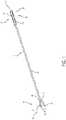
- FIGs. 1-4Cillustrate various example capsulorhexis forceps 10 and a forceps tip 11 thereof.
- FIGS. 5 and 6further illustrate example implementations of the capsulorhexis forceps 10 included with different handle assemblies 12 ( FIGs. 5 and 6 ).
- the handle assemblies 12are operable to manipulate/operate the capsulorhexis forceps 10.
- the capsulorhexis forceps 10include a forceps tip 11.
- the forceps tip 11includes an elongated tip body 15.
- the tip body 15may extend approximately 2 to 4 inches (50 mm to 100 mm) in length. However, the tip body 15 may have a length larger or smaller than the above-indicated range.
- a pair of resilient pincers 17is formed at a distal end 16 of the tip body 15.
- the pincers 17extend from a location 18 along the tip body 15.
- the pincers 17include grasping surfaces 22 and tips 19 formed at distal ends thereof.
- the tips 19may terminate in a pointed end 23.
- the tips 19may not include a pointed end. Rather, in some implementations, the tips 19 may be blunt
- the tips 19may have a hooked shape, as shown, for example, in FIG. 2A .
- the hook-shaped tip 19may also include a pointed end 23. Alternately, the hook-shaped tips 19 may not include a pointed end.
- the pincers 17are spaced apart from each other in a spread-apart or open configuration ("open configuration").
- the grasping surfaces 22may include one or more sharp edges, such as one or more sharp edges 200, 202, 204.
- the sharp edges 200, 202, 204may be used to penetrate a lens capsule of an eye.
- the grasping surfaces 22may have a plurality of serrations 29 formed therein.
- the spacing between serrationsmay be 0.1 mm or less. However, in other implementations, the spacing between serrations may be greater than 0.1 mm.
- the grasping surfaces 22may be used to grasp the lens capsule of an eye, such as, by pinching the capsule between the grasping surfaces 22.
- An opening in the lens capsulemay be made by tearing the capsule with the forceps while the lens capsule is pinched between the grasping surfaces 22.
- a forceps tip 11may be used to puncture the lens capsule.
- a forceps tip 11that includes one or more of sharp edges 200, 202, 204 may be used to puncture the lens capsule.
- An openingmay be increased in size by grasping the lens capsule with the forceps tip 11 and tearing the capsule tissue to enlarge the opening.
- the forceps tip 11may be formed from a moldable material.
- the forceps tip 11may be formed from a polymeric material that is formable, such as via injection molding.
- the forceps tip 11may be utilized as a disposable forceps tip.
- the forceps tip 11may be used as a disposable insert that can be adjustably mounted within a reusable handle 12, as indicated in Figs. 5 and 6 .
- the forceps tip 11may be disposed of after use.
- the forceps tip 11 along with the handle 12may be a single-use instrument that is disposable in its entirety at the conclusion of a use, such as a surgical procedure.
- the forceps tip 11may be molded or otherwise formed from a synthetic or composite material.
- the forceps tip 11may be formed from a medical grade plastic.
- the forceps tip 11may be formed from other materials, such as a metal injection molded material that is suitable for medical applications.
- a polyoxymethylene acetyl copolymer high-strength medical grade resin material, or other, similar moldable copolymer materialmay be used.
- a high strength, medical grade materialthat is suitable for both medical use and for microinjection molding may be used.
- a medical grade moldable materialsuch as one or more of the materials described above, may also be enriched with other fibers or materials (referred to collectively as "additives") to enhance strength, rigidity, and/or resiliency.
- Example additivesmay include approximately 5-30% glass bead or 1-10% glass fiber. However, higher or lower concentrations of one or more of the above additives or other suitable additives may also be used to enhance physical properties of the forceps tip 11, such as, for example, to provide enhanced strength, rigidity, and/or resiliency to the forceps tip 11.
- the forceps tip 11also may be made from metal injection molded materials utilizing a metal injection molding process.
- the forceps tip 11may be formed using a material such as a stainless steel or other moldable/metal injectable materials.
- metal injectable materials suitable for use in medical applicationsmay be used to form the forceps tip 11.
- the pincers 17may be formed such that the pincers 17 are biased in the open configuration.
- the pincers 17are moveable toward each other into a second, substantially closed or grasping/gripping position ("grasping configuration).
- the pincers 17are displaced towards each other.
- the pincers 17 and particularly the tips 19are operable to grasp objects, such as tissues, with the grasping surfaces 22.
- the tips 19 of the pincers 17may be utilized to engage and grip a capsulorhexis flap formed in the patient's eye or a replacement lens for positioning into the patient's eye
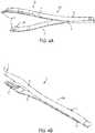
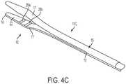
- FIGs. 4A-4Cillustrate other example implementations of the forceps tip 11A-11C having differing grasping surfaces 22.
- FIGs. 4A and 7illustrate the forceps tip 11A in which the grasping surfaces 22 are angled.
- FIG. 7shows a detail view of a distal end of a pincer 17 shown in FIG. 4A .
- the grasping surface 22may be disposed at an angle ⁇ relative to longitudinal axis 24.
- the grasping surfaces 22may include surface structures, features, and/or texturing operable to enhance grasping and adhesion performance of the forceps 10. For example, addition of one or more of these or other features to the grasping surface 22 may provide enhance performance when utilized to grasp and retain a lens, a membrane, or a capsulorhexis flap.
- FIG. 4Billustrates another implementation in which the grasping surfaces 22 include a plurality of ridges, grooves, serrations, or teeth (collectively referred to as "serrations") 29. In some instances, the spacing between adjacent serrations 29 may be 0.13 mm. In other instances, the serration 29 may have any number of shapes. For example, the serrations 29 may have a pyramid, cubical, rounded, or other raised shape.
- the grasping surface 22may be substantially flat. In still other instances, the grasping surface 22 may have a desired surface roughness. Further, as shown in FIGS. 2A , 4A , 4B , and 4C , the grasping surfaces 22 may be formed on a raised shelf 28. Also, as shown in FIG. 4C , the raised shelf may be a plurality of raised shelves offset from each other, such as shelves 28a and 28b. The plurality of shelves 28a and 28b results in the grasping surface 22 form a tiered surface. In still other implementations, the grasping surfaces 22 may include blind holes, recesses, or other surface features to enhance grasping and adhesion properties of the forceps 10.
- a proximal end 35 of the tip body 15generally is positioned proximally of the intermediate point 18 and pincers 17.
- the proximal end 35defines a connection end of the forceps tip 11.
- the second end 35is operable to connect the forceps tip 11 to a handle, such as the example handle 12 shown in FIGs. 5 and 6 .
- the second end 35may include a tip connector 36.
- Example tip connectors 36are illustrated in FIGs. 1 , 2B , and 3 .
- the tip connector 36may include a first set of teeth 37 and a second set of teeth 38. Referring to FIG. 3 , the first set of teeth 37 is formed along a first side 41 of the tip body 15 adjacent the proximal end 35, and the second set of teeth 38 is formed along a second side 42 of tip body 15, opposite the first side 41, adjacent the proximal end 35.
- Each of the first set of teeth 37 and the second set of teeth 38may include a plurality of teeth 39.
- the teeth 39may have a first surface 47 and a second surface 48. As shown in FIG. 3 , the first surface 47 slopes outwardly (i.e., away from the longitudinal axis 21) towards the distal end 16.
- the second surface 48may be perpendicular or substantially perpendicular to the longitudinal axis 1.
- Each tooth 39 of the first and second sets of teeth 37, 38may include a tooth length L defined as the distance between a location where adjacent second surfaces 48 meet the tip body 15.
- the tooth length Lmay be approximately 0.1 mm to 0.15 mm. In other instances, the tooth length L may vary from this range. For example, in some instances, the tooth length L may be greater than 0.15 mm or less than 0.1 mm.
- the first set of teeth 37may be longitudinally offset from the second set of teeth 38 about longitudinal axis 21. That is, in some implementations, teeth 39 within the first set of teeth 37 are staggered from and not aligned with teeth 39 within the second set of teeth 38. As shown in FIG.
- the teeth 39 within the first set of teeth 37are offset from the teeth 39 in the second set of teeth 38 by a distance S.
- the distance Smay be one half of the tooth length L.
- the distance Smay be within the range of approximately 0.05 mm to approximately 0.075 mm.
- the distance Smay be any desired distance. For example, a larger or smaller distance S may be used.
- the distance Smay vary depending on, for example, the tooth length L or may be independent of tooth length L.
- the staggered relationship between the first set of teeth 37 and the second set of teeth 38may be utilized to provide a stepped adjustment of the position of the forceps tip 15 within the handle 12 by an amount that is smaller than the tooth length L.
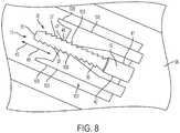
- a position of the forceps tip 11 relative to the handle 12may be adjusted incrementally by successive distances S, for example, in the directions of arrow 49, as shown, for example, in FIG. 8 .
- other spacings or arrangements of the first set of teeth 37 and the second set of teeth 38, as well as the use of fewer or additional sets of teethmay also be provided as needed or desired.
- the teeth 39may be integrally formed with the tip body 15.
- the teeth 39may be molded, extruded, or otherwise formed with the tip body 15.
- the teeth 39may be formed separately from tip body 15.
- the tip connector 36 including the first and second sets of teeth 37, 38may be formed as a separate piece and coupled to the tip body 15.
- the tip connector 36may be coupled directly or indirectly to the tip body.
- the tip connector 36may be coupled to the tip body by, for example, welding, an adhesive, press fit, interlocking mechanism, or in any other suitable way.
- FIGs. 2A and 2Billustrate another example implementation of the forceps tip 11.
- the forceps tip 11includes a tip body 15 that is coupled to a tip extension 51.
- the tip body 15may have a configuration similar to that explained above and may include a receptacle 54.
- the tip extension 51may be an elongated wire or rod.
- a distal end 53 of the extension 51is received into the receptacle 54 of the tip body 15.
- a proximal end 52 of the extension 51may include a tip connector 36.
- the tip connector 36may be configured as explained above.
- a length of each of the tip body 15 and the extension 51may be any desired length.
- the tip body 15may have a length of approximately one half of an inch to one inch (i.e., 12.5 mm to 25 mm)
- a sleeve 57may be received over at least a portion of the tip body 15 of the forceps tip 11.
- the sleeve 57may be received over a portion of the tip extension 51.
- the sleeve 57is slideable over the forceps tip 11 in the direction arrows 58 and 58'.
- a distal end 55engages proximal portions 59 of the pincers 17, causing the tips 19 to be urged inwardly toward each other in the direction of arrows 61.
- the proximal portions 59 of the pincers 17are at least partially received into passage 56 defined by the sleeve 57. Consequently, movement of the sleeve 57 in the direction of arrow 58 is operable to move the pincers 17 into a closed or grasping configuration. Movement of the sleeve 57 in the direction of arrow 58' causes the proximal portions 59 to be removed from the passage 56. As a result, the tips 19 of the pincers 17 move away from each other due to the resilient quality of the pincers 17. Therefore, the displacement of the sleeve 57 in the directions of 58 and 58' is operable to close and open the pincers 17, respectively.
- the interaction between the sleeve 57 and the pincers 17is operable to cause the pincers 17, for example, to grasp a capsulorhexis flap or to grip a replacement lens for insertion into a patients eye.
- the sleeve 57may be formed from any suitable material.
- the sleeve 57may be formed from a metal or polymeric material.
- the sleeve 57may be formed from materials that are medical grade quality.
- the material selected to form the different components described hereinmay be selected based, at least in part, on whether the component is to be part of a reusable instrument or a single use disposable instrument.
- FIGs. 5 and 6illustrate different example devices 100, 200.
- the handle 12may be formed from a variety of materials.
- the handle 12may be formed from one or more plastics, synthetic materials (e.g., synthetic fibers or synthetic diamond), composites, and/or metals.
- a material selected for forming the handle 12may be based, at least in part, on whether the device, e.g., devices 100, 200, is to be re-useable or a disposable.
- the handle 12may include arm elements 73 and 74. As shown in FIGS. 5 and 6 , an elongate element 96 is disposed between the arm elements 73, 74. The arm elements 73 and 74 are coupled at a union 79 at a proximal end 72 of the handle 12 and diverge outwardly away from the elongate element 96. Referring to the example device 200 of FIG. 6 , a proximal end 79 of the elongate member 96 may include one or more mating features 98 (e.g., protrusions, projections, teeth, roughened surface, ribs, etc.) formed on an outer surface of the elongate member 96 that engage with corresponding engaging features 99 formed on an inner surface 94 of the handle 12. The engaging features 98, 99 cooperate to lock the elongate member 96 in place.
- mating features 98e.g., protrusions, projections, teeth, roughened surface, ribs, etc.
- the devices 100, 200may also include a tip guide 85.
- the tip guide 85may include a sleeve 57 and a hub 86.
- the sleeve 57 and the hub 86may be formed from the same material. Further, in some instances, the sleeve 57 and the hub 86 may be integrally formed. In other instances, the sleeve 57 and the hub 86 may be formed from different materials. For example, in some instances, the sleeve 57 may be formed from a metal, such as stainless steel, whereas the hub 86 may be formed from a polymeric material. Additionally, the hub 86 may have a semi-hemispherical shape (as shown in FIG. 6 ) or a cylindrical shape (as shown in FIG. 5 ). However, the hub 86 may have any desired shape.
- the tip guide 85may be coupled to the arm elements 73, 74 via resilient elements 88.
- the resilient elements 88may be coupled to the arm elements 73, 74 at distal ends 71 thereof.
- the resilient elements 88provide a biasing formed to return the pincers of the forceps tip to an open configuration.
- the arm elements 73, 74; the resilient elements 88; and the hub 86may be integrally formed.
- the device 100includes four hinged elements 89 that are connected to the arm elements 73, 74 and the tip guide 85 via hinges 102 and 104. Additional or fewer hinged elements 89 may be included.
- the hinged elements 89are operable to pivot about hinges 102 and 104 to displace the sleeve 57 distally when the arm elements 73, 74 are urged towards each other. Operation of the devices 100, 200 is described in more detail below.
- the tip guide 85defines a passage 87.
- a forceps tip 11extends through the passage 87.
- the forceps tip 11may include a tip connector 36.
- the tip connector 36is adapted to couple to the device 200 via a locking mechanism 101.
- the locking mechanism 101may be formed in a distal end 112 of the elongate element 96.
- the locking mechanism 101is described in relation to the device 200, the device 100 may also include a locking mechanism that is similar to the locking mechanism 101.
- the locking mechanism 101is operable to adjustably secure the forceps tip 11.
- the locking mechanism 101includes locking members 106.
- the locking members 106include mating teeth 108 that cooperatively engage with the teeth 39 of the tip connector 36 as illustrated in FIG. 8 .
- the mating teeth 108are adapted to engage the first and second set of teeth 37, 38 formed on the tip connector 36.
- the teeth 39 of the first and second sets of teeth 37, 38are passed between the locking members 106.
- the sloping surface of the first surface 47 of the teeth 39causes the locking members 106 to be deflected outwardly away from the forceps tip 11.
- the locking members 106return to their initial positions.
- FIGS. 12 and 13illustrate alternative locking mechanisms 101.
- the elongate member 96defines a slot 97.
- the locking mechanism 101includes locking members 106 disposed in the slot 97.
- the locking members 106are integrally formed with walls 107 defining the slot 97 and include mating teeth 108. Similar to those described above, the mating teeth 108 are adapted to cooperatively engage with teeth 39 formed on the forceps tip 11. As the forceps tip 11 (not shown) is passed between the locking members 106, the teeth 39 of the forceps tip 11 are operable to pass in the direction of arrow 49 past the mating teeth 108. As the teeth 39 pass the mating teeth 108, the teeth 39 cause the locking member 106 to separate laterally.
- the walls 107flex in response to movement of the forceps tip 11 between the locking members 106. Also similar to the locking mechanism 101 shown in FIG. 8 , the locking members 106 prevent movement of the forceps tip 11 in the direction opposite of arrow 49 due to the interlocking fit between teeth 39 and mating teeth 108.
- the elongate member 96defines a slot 97.
- the locking members 106protrude into the slot 97 and are adapted to engage the teeth 39 of the forceps tip 11 with mating teeth 108.
- the locking members 106are pivotably coupled to the elongate member 96 at bases 111.
- Each of the locking members 106is disposed in a slot 113.
- the slots 113may be formed perpendicular to the slot 97. Further, in some implementations, the locking members 106 may be formed integrally with the elongate member 96.
- the locking members 106are adapted to flex laterally outwards as the teeth 39 of the forceps tip 11 pass the mating teeth 108 when the forceps tip 11 is moved in the direction of arrow 49. Similar to the locking members 106 of the locking mechanism 101 shown in FIGs. 8 and 12 , the locking members 106 are biased to return to their original position in response to movement of the teeth 39 and mating teeth 108 relative to each other. Also, interlocking of the teeth 39 and mating teeth 108 prevents movement of the forceps tip 11 relative to the elongate member 96 in the direction opposite arrow 49.
- the locking mechanism 101is adapted to permit movement of the forceps tip 11 in only one direction, i.e., direction 49.
- the teeth 39 of the first and second sets of teeth 37, 38may be offset from each other by a distance S.
- the teeth 108may similarly be offset by a distance S.
- the interaction between one of the teeth 39 with the teeth 108is operable to immobilize the forceps tip 11 within the device 200.
- the offset distance S between the first and second sets of teeth 37, 38allows for stepped adjustment in position of the forceps tip 11, providing a more precise location of the forceps tip 11 within the device 200. This is particularly important in order to precisely locate the pincers 17 relative to the distal end 55 of the sleeve 57.
- Precisely locating the pincers 17 relative to the sleeve 57allows, for example, the pincers to be in their fully open configuration when the device 100, 200 is in an unactuated condition and immediate movement of the pincers 17 towards each other when a user applies a force to urge the arm elements 73, is toward each other due to contact of the distal end 55 of the sleeve 57 with the pincers 17.
- positioning of the forceps tip 11 within the locking mechanism 101may be performed during assembly and fixed in place with an adhesive, for example. However, in other instances, the forceps tip 11 may be positioned within the locking mechanism 101 at other times.
- the locking members 106may also include protrusions 109.
- the protrusions 109may be moved away from each other to release the forceps tip 11 from engagement with the locking members 106. This may be useful if the forceps tip 11 has been positioned too far in the direction of arrow 49. Separation of the protrusions 109 and, hence, the locking members 106 allows for the forceps tip 11 to be repositioned. For example, the forceps tip 11 may be moved in the position of arrow 49' upon separation of the protrusions 109.
- the described operationis also applicable to the device 100.
- the pincers 17 of the device 200are in a fully-open state.
- the sleeve 57 and hub 86are displaced in the direction of arrow 58 via distal movement of ends of the resilient elements 88 that are coupled to the hub 86.
- the distal end 55 of the sleeve 57engages the pincers 17, causing the tips 19 of the pincers 17 to move towards each other into a closed configuration.
- the tips 19are, accordingly, moved closer together.
- the arm elements 73, 74return to their at-rest position.
- the resilient elements 88displace sleeve 57 and hub 86 in the direction of arrow 58' relative to the forceps tip 11, causing the tips 19 to move away from each other due to the resilient properties of the pincer 17.
- the pincers 17continue to move away from each other until the arm elements 73, 74 have attained their at-rest position.
- the device 200may include a sleeve 150.
- the sleeve 150may be positioned over the interface between the locking mechanism 101 and the tip connector 36 of the forceps tip 11.
- the sleeve 150may include a cam-shaped lip 152.
- the cam shape of the lip 152defines lobes 115.
- the lobes 115may be positioned relative to one of the arm elements 73, 74 by rotation of the sleeve 150 about longitudinal axis 114.
- the rim 152 and, particularly, the lobes 115limit an amount of actuation of the device 200 as a result of contact between the arm elements 73, 74 and the rim 152.
- the amount of displacement of the arm elements 73, 74may be varied based on the rotational position of the rim 152 relative to the arm elements 73, 74.
- a position of the lobes 115 relative to the arm elements 73, 74defines an endstop to limit an amount of displacement of the arm elements 73, 74.
- a position where one of the arm elements 73, 74 contacts rim 152defines a fully actuated position of the device 200. Consequently, a rotational position of the rim 152 is operable to limit an amount by which the sleeve 57 is moved relative to the forceps tip 11.
- a position of the sleeve 150may be selected during assembly of the device 200 or some other time.
- the sleeve 150may be fixed into place, for example, with an adhesive. While an example sleeve 150 is shown with a pair of lobes 115, other sleeves 150 may have a different number of lobes 115. For example, another example sleeve 150 may have a single lobe 115. In other instances, the sleeve 150 may have more than two lobes 115.
- the present disclosureprovides for a forceps tip and, more generally, a forceps device that can be economically and efficiently mass produced from molded medical grade materials.
- the forceps devicemay be utilized in a capsulorhexis procedure. Further, the forceps device may be disposable after a single use.
- the forceps tipmay also be easily and securely inserted into and removed from a handle of the forceps device, with the position of the forceps tip being adjustable with respect to the handle.
Landscapes
- Health & Medical Sciences (AREA)
- Surgery (AREA)
- Life Sciences & Earth Sciences (AREA)
- Engineering & Computer Science (AREA)
- Veterinary Medicine (AREA)
- Nuclear Medicine, Radiotherapy & Molecular Imaging (AREA)
- Heart & Thoracic Surgery (AREA)
- Biomedical Technology (AREA)
- Animal Behavior & Ethology (AREA)
- General Health & Medical Sciences (AREA)
- Public Health (AREA)
- Ophthalmology & Optometry (AREA)
- Molecular Biology (AREA)
- Medical Informatics (AREA)
- Vascular Medicine (AREA)
- Surgical Instruments (AREA)
- Physics & Mathematics (AREA)
- Plasma & Fusion (AREA)
- Otolaryngology (AREA)
Description
- The present disclosure generally relates to surgical instruments, and in particular to a capsulorhexis forceps for use in ophthalmic surgeries, that can have a disposable forceps tip that can be inexpensively molded or extruded.
- Cataracts occur when the natural lens of a person's eye or its surrounding transparent membrane becomes clouded, resulting in various degrees of visual impairment. In response to the development of cataracts in a person's eye, several surgical techniques have been developed for cataract extraction. In general, during such cataract surgeries, the surgeon will make an incision through an anterior portion of the lens capsule of the eye to create a flap or opening through which the surgeon can remove the damaged portion of the eye. For example, in a continuous curvilinear capsulorhexis type of capsulotomy, the periphery of the lens generally is opened using the sharp tips of a capsulorhexis forceps. The tips of the forceps are then used to create an opening through which damaged lens material can be removed and an artificial replacement lens can be inserted.
- The principal tool used for such cataract surgeries typically is a capsulorhexis forceps. Such capsulorhexis forceps generally are formed with a handle portion designed to be grasped by the surgeon and a pair of sharp tips that are used for both creating a flap and tearing the tissue, and for grasping the lens.
- Document
WO97/15234 claim 1. - The forceps device of the invention is defined in
independent claim 1. Preferred embodiments are defined in the dependent claims. - According to one aspect, the disclosure describes a forceps device including a handle, a forceps tip, and a sleeve. The handle may include a first arm element, a second arm element, the first arm element and the second arm element joined at a first end of the handle, an elongate body extending between the first arm element and the second arm element, and a locking mechanism formed in the elongate body. The forceps tip may be coupled to the handle and may include a pair of pincers extending from a distal end of the forceps tip. The pair of pincers may be laterally offset from each other to define an open configuration. The pincers may be moveable between the open configuration and a closed configuration in which the pair of pincers contact each other. The forceps tip may also include a tip connector extending from a proximal end of the forceps tip. The tip connector may be adapted to interlock with the locking mechanism. The sleeve may be coupled to the arm elements and define a central passage. The forceps tip may extend through the central passage. The sleeve may be operable to move relative to the forceps tip and actuate the pincers between the open configuration and the closed configuration in response to lateral displacement of the arm elements.
- Another aspect of the disclosure encompasses a forceps that includes a forceps tip having a first end and a second end, a pair of resilient pincers formed at the first end of the tip body and moveable between an open position and a closed position, and a tip connector formed at the second end of the forceps tip. The tip connector may include a plurality of teeth adapted to selectively engage a handle. The pincers may be biased toward the opened position.
- The various aspects may include one or more of the following features. Resilient elements may extend between distal ends of the arm elements and the sleeve. A distal end of at least one of the pincers may include a grasping surface. The grasping surface may include a series of serrations. The forceps tip may include a tip body and a tip extension coupled to the tip body. The tip body may include the pair of pincers, and the tip extension may include the tip connector. The tip connector may include a first plurality of teeth arranged longitudinally along the forceps tip. The locking mechanism may include a, second plurality of teeth. The second plurality of teeth may be configured to interlock with the first plurality of teeth to couple the forceps tip to the handle. The first plurality of teeth may include a first set of teeth extending longitudinally along a first side of the tip connector and a second set of teeth may extending longitudinally along a second side of the tip connector. The second plurality of teeth may include a third set of teeth configured to interlock with the first set of teeth and a fourth set of teeth configured to interlock with the second set of teeth. The first set of teeth and the second set of teeth may be longitudinally offset from each other. The third set of teeth and the fourth set of teeth may be offset from each other by the same amount the first set of teeth is offset from the second set of teeth.
- The forceps tip may be formed from a plastic injection molded material. The forceps tip may be formed from a metal injection molded material. The locking mechanism may also include a first locking member and a second locking member. The first set of teeth may be formed on the first locking member, and the second set of teeth may be formed on the second locking member. The first locking member and the second locking member may be laterally movable. The handle may also include a first resilient element extending between the first arm element and the sleeve and a second resilient element extending between the second arm element and the sleeve.
- The various aspects may also include one or more of the following features. The first end of the forceps tip may also include grasping surfaces formed on facing surfaces of the pincers. The grasping surfaces may include serrations. The plurality of teeth may include a first set of teeth arranged in series along a first side surface of the tip body and a second set of teeth arranged in series along a second side surface of the tip body. The first set of teeth may be offset from the second set of teeth. Each of the teeth of the first set of teeth and the second sets of teeth may have a tooth length, and the first set of teeth may be offset from the second set of teeth by a distance of approximately one half of the tooth length. The tip body may be formed from a material selected from the group comprising an injection molded plastic, a composite material, and a metal injection molded material.
- Various features, objects and advantages of the present will become apparent to those skilled in the art upon a review of the following detailed description, when taken in conjunction with the accompanying drawings.
FIG. 1 is a perspective view of an example capsulorhexis forceps tip.FIG. 2A is a perspective view of another example capsulorhexis forceps tip.FIG. 2B is a perspective view of an example capsulorhexis forceps tip with an extension member attached thereto.FIG. 2C is a side view of an example capsulorhexis forceps tip with a movable sleeve extending along a tip body.FIG. 3 is a perspective view of an example tip connector.FIGs. 4A-4C are perspective views of example capsulorhexis forceps tips.FIG. 5 is a perspective view of an example capsulorhexis forceps mounted within a handle assembly with an insert connector.FIG. 6 is a side view of an example capsulorhexis forceps tip mounted within a handle assembly with an insert connector.FIG. 7 is a detail view of an example forceps tip in which the grasping surfaces of the pincers are angled.FIG. 8 is a perspective view of an example locking mechanism of the insert connector of the handle ofFIG. 6 engaging a tip connector of the forceps tip.FIG. 9 is a cross-sectional view of a locking mechanism of the example device ofFIG. 6 .FIG. 10 is an end view of a sleeve adapted to define a fully actuated position of the example device ofFIG. 6 .FIG. 11 is a detail view of grasping surfaces of an example capsulorhexis forceps tip.FIGs. 12 and13 show alternative locking mechanisms operable to adjustably secure a forceps tip.- Those skilled in the art will appreciate and understand that, according to common practice, the various features of the drawings discussed below are not necessarily drawn to scale, and that the dimensions of various features and elements of the drawings may be expanded or reduced to more clearly illustrate the various implementations described herein.
- Referring now to the drawings in greater detail in which like numerals indicate like parts throughout the several views, capsulorhexis forceps adapted for use in ophthalmic surgeries such as for the correction of cataracts in a patient's eye are described.
FIGs. 1-4C illustrate variousexample capsulorhexis forceps 10 and aforceps tip 11 thereof.FIGS. 5 and6 further illustrate example implementations of the capsulorhexis forceps 10 included with different handle assemblies 12 (FIGs. 5 and6 ). Thehandle assemblies 12 are operable to manipulate/operate thecapsulorhexis forceps 10. As indicated inFIGs. 1-2A and4A-4C , thecapsulorhexis forceps 10 include aforceps tip 11. Theforceps tip 11 includes anelongated tip body 15. In some implementations, thetip body 15 may extend approximately 2 to 4 inches (50 mm to 100 mm) in length. However, thetip body 15 may have a length larger or smaller than the above-indicated range.- A pair of
resilient pincers 17 is formed at adistal end 16 of thetip body 15. Thepincers 17 extend from alocation 18 along thetip body 15. Further, thepincers 17 include graspingsurfaces 22 andtips 19 formed at distal ends thereof. Further, in some implementations, thetips 19 may terminate in apointed end 23. In other implementations, thetips 19 may not include a pointed end. Rather, in some implementations, thetips 19 may be blunt In still other implementations, thetips 19 may have a hooked shape, as shown, for example, inFIG. 2A . The hook-shapedtip 19 may also include apointed end 23. Alternately, the hook-shapedtips 19 may not include a pointed end. As shown, thepincers 17 are spaced apart from each other in a spread-apart or open configuration ("open configuration"). Referring toFIG. 11 , the graspingsurfaces 22 may include one or more sharp edges, such as one or moresharp edges sharp edges FIG. 2A , the graspingsurfaces 22 may have a plurality ofserrations 29 formed therein. In some implementations, the spacing between serrations may be 0.1 mm or less. However, in other implementations, the spacing between serrations may be greater than 0.1 mm. - The grasping surfaces 22 may be used to grasp the lens capsule of an eye, such as, by pinching the capsule between the grasping surfaces 22. An opening in the lens capsule may be made by tearing the capsule with the forceps while the lens capsule is pinched between the grasping surfaces 22. In other instances, a
forceps tip 11 may be used to puncture the lens capsule. For example, aforceps tip 11 that includes one or more ofsharp edges forceps tip 11 and tearing the capsule tissue to enlarge the opening. - The
forceps tip 11 may be formed from a moldable material. For example, theforceps tip 11 may be formed from a polymeric material that is formable, such as via injection molding. Thus, theforceps tip 11 may be utilized as a disposable forceps tip. For example, theforceps tip 11 may be used as a disposable insert that can be adjustably mounted within areusable handle 12, as indicated inFigs. 5 and6 . Thus, as a disposable insert, theforceps tip 11 may be disposed of after use. In other instances, theforceps tip 11 along with thehandle 12 may be a single-use instrument that is disposable in its entirety at the conclusion of a use, such as a surgical procedure. - In some implementations, the
forceps tip 11 may be molded or otherwise formed from a synthetic or composite material. For example, theforceps tip 11 may be formed from a medical grade plastic. In still other implementations, theforceps tip 11 may be formed from other materials, such as a metal injection molded material that is suitable for medical applications. For example, a polyoxymethylene acetyl copolymer high-strength medical grade resin material, or other, similar moldable copolymer material may be used. Particularly, a high strength, medical grade material that is suitable for both medical use and for microinjection molding may be used. - In addition, a medical grade moldable material, such as one or more of the materials described above, may also be enriched with other fibers or materials (referred to collectively as "additives") to enhance strength, rigidity, and/or resiliency. Example additives may include approximately 5-30% glass bead or 1-10% glass fiber. However, higher or lower concentrations of one or more of the above additives or other suitable additives may also be used to enhance physical properties of the
forceps tip 11, such as, for example, to provide enhanced strength, rigidity, and/or resiliency to theforceps tip 11. - Still further, in other implementations, the
forceps tip 11 also may be made from metal injection molded materials utilizing a metal injection molding process. For example, theforceps tip 11 may be formed using a material such as a stainless steel or other moldable/metal injectable materials. Particularly, metal injectable materials suitable for use in medical applications may be used to form theforceps tip 11. - As indicated above, the
pincers 17 may be formed such that thepincers 17 are biased in the open configuration. Thepincers 17 are moveable toward each other into a second, substantially closed or grasping/gripping position ("grasping configuration). In the grasping configuration, thepincers 17 are displaced towards each other. In the grasping configuration, thepincers 17 and particularly thetips 19 are operable to grasp objects, such as tissues, with the grasping surfaces 22. For example, in some implementations, thetips 19 of thepincers 17 may be utilized to engage and grip a capsulorhexis flap formed in the patient's eye or a replacement lens for positioning into the patient's eye FIGs. 4A-4C illustrate other example implementations of theforceps tip 11A-11C having differing grasping surfaces 22.FIGs. 4A and7 illustrate theforceps tip 11A in which the graspingsurfaces 22 are angled.FIG. 7 shows a detail view of a distal end of apincer 17 shown inFIG. 4A . As shown, the graspingsurface 22 may be disposed at an angle θ relative tolongitudinal axis 24.- The grasping surfaces 22 may include surface structures, features, and/or texturing operable to enhance grasping and adhesion performance of the
forceps 10. For example, addition of one or more of these or other features to the graspingsurface 22 may provide enhance performance when utilized to grasp and retain a lens, a membrane, or a capsulorhexis flap.FIG. 4B illustrates another implementation in which the graspingsurfaces 22 include a plurality of ridges, grooves, serrations, or teeth (collectively referred to as "serrations") 29. In some instances, the spacing betweenadjacent serrations 29 may be 0.13 mm. In other instances, theserration 29 may have any number of shapes. For example, theserrations 29 may have a pyramid, cubical, rounded, or other raised shape. Alternately, the graspingsurface 22 may be substantially flat. In still other instances, the graspingsurface 22 may have a desired surface roughness. Further, as shown inFIGS. 2A ,4A ,4B , and4C , the graspingsurfaces 22 may be formed on a raisedshelf 28. Also, as shown inFIG. 4C , the raised shelf may be a plurality of raised shelves offset from each other, such asshelves 28a and 28b. The plurality ofshelves 28a and 28b results in the graspingsurface 22 form a tiered surface. In still other implementations, the graspingsurfaces 22 may include blind holes, recesses, or other surface features to enhance grasping and adhesion properties of theforceps 10. - Referring again to
FIGs. 1 and2A , aproximal end 35 of thetip body 15 generally is positioned proximally of theintermediate point 18 andpincers 17. Theproximal end 35 defines a connection end of theforceps tip 11. Thesecond end 35 is operable to connect theforceps tip 11 to a handle, such as the example handle 12 shown inFIGs. 5 and6 . - In some implementations, the
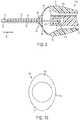
second end 35 may include atip connector 36.Example tip connectors 36 are illustrated inFIGs. 1 ,2B , and3 . Thetip connector 36 may include a first set ofteeth 37 and a second set ofteeth 38. Referring toFIG. 3 , the first set ofteeth 37 is formed along afirst side 41 of thetip body 15 adjacent theproximal end 35, and the second set ofteeth 38 is formed along asecond side 42 oftip body 15, opposite thefirst side 41, adjacent theproximal end 35. Each of the first set ofteeth 37 and the second set ofteeth 38 may include a plurality ofteeth 39. Theteeth 39 may have afirst surface 47 and asecond surface 48. As shown inFIG. 3 , thefirst surface 47 slopes outwardly (i.e., away from the longitudinal axis 21) towards thedistal end 16. Thesecond surface 48 may be perpendicular or substantially perpendicular to thelongitudinal axis 1. - Each
tooth 39 of the first and second sets ofteeth second surfaces 48 meet thetip body 15. In some instances, the tooth length L may be approximately 0.1 mm to 0.15 mm. In other instances, the tooth length L may vary from this range. For example, in some instances, the tooth length L may be greater than 0.15 mm or less than 0.1 mm. The first set ofteeth 37 may be longitudinally offset from the second set ofteeth 38 aboutlongitudinal axis 21. That is, in some implementations,teeth 39 within the first set ofteeth 37 are staggered from and not aligned withteeth 39 within the second set ofteeth 38. As shown inFIG. 3 , theteeth 39 within the first set ofteeth 37 are offset from theteeth 39 in the second set ofteeth 38 by a distance S. In some implementations, the distance S may be one half of the tooth length L. In some implementations, the distance S may be within the range of approximately 0.05 mm to approximately 0.075 mm. However, the distance S may be any desired distance. For example, a larger or smaller distance S may be used. Further, the distance S may vary depending on, for example, the tooth length L or may be independent of tooth length L. - Referring to
FIG. 3 , the staggered relationship between the first set ofteeth 37 and the second set ofteeth 38 may be utilized to provide a stepped adjustment of the position of theforceps tip 15 within thehandle 12 by an amount that is smaller than the tooth length L. Thus, in some implementations, a position of theforceps tip 11 relative to thehandle 12 may be adjusted incrementally by successive distances S, for example, in the directions ofarrow 49, as shown, for example, inFIG. 8 . It further will be understood that other spacings or arrangements of the first set ofteeth 37 and the second set ofteeth 38, as well as the use of fewer or additional sets of teeth, may also be provided as needed or desired. - The
teeth 39 may be integrally formed with thetip body 15. For example, theteeth 39 may be molded, extruded, or otherwise formed with thetip body 15. In other implementations, theteeth 39 may be formed separately fromtip body 15. For example, thetip connector 36 including the first and second sets ofteeth tip body 15. For example, thetip connector 36 may be coupled directly or indirectly to the tip body. Further, thetip connector 36 may be coupled to the tip body by, for example, welding, an adhesive, press fit, interlocking mechanism, or in any other suitable way. FIGs. 2A and2B illustrate another example implementation of theforceps tip 11. In this implementation, theforceps tip 11 includes atip body 15 that is coupled to atip extension 51. Thetip body 15 may have a configuration similar to that explained above and may include a receptacle 54. In some instances, thetip extension 51 may be an elongated wire or rod. Adistal end 53 of theextension 51 is received into the receptacle 54 of thetip body 15. Aproximal end 52 of theextension 51 may include atip connector 36. Thetip connector 36 may be configured as explained above. A length of each of thetip body 15 and theextension 51 may be any desired length. In some instances, thetip body 15 may have a length of approximately one half of an inch to one inch (i.e., 12.5 mm to 25 mm)- Referring to
FIG. 2C , asleeve 57 may be received over at least a portion of thetip body 15 of theforceps tip 11. For implementations utilizing atip extension 51, thesleeve 57 may be received over a portion of thetip extension 51. Thesleeve 57 is slideable over theforceps tip 11 in thedirection arrows 58 and 58'. As the sleeve. 57 is moved along thetip body 11 in the direction ofarrow 58, adistal end 55 engagesproximal portions 59 of thepincers 17, causing thetips 19 to be urged inwardly toward each other in the direction ofarrows 61. As thepincers 17 are displaced towards each other, theproximal portions 59 of thepincers 17 are at least partially received intopassage 56 defined by thesleeve 57. Consequently, movement of thesleeve 57 in the direction ofarrow 58 is operable to move thepincers 17 into a closed or grasping configuration. Movement of thesleeve 57 in the direction of arrow 58' causes theproximal portions 59 to be removed from thepassage 56. As a result, thetips 19 of thepincers 17 move away from each other due to the resilient quality of thepincers 17. Therefore, the displacement of thesleeve 57 in the directions of 58 and 58' is operable to close and open thepincers 17, respectively. In the context of a capsulorhexis procedure, the interaction between thesleeve 57 and thepincers 17 is operable to cause thepincers 17, for example, to grasp a capsulorhexis flap or to grip a replacement lens for insertion into a patients eye. - The
sleeve 57 may be formed from any suitable material. For example, thesleeve 57 may be formed from a metal or polymeric material. Particularly, thesleeve 57 may be formed from materials that are medical grade quality. Further, the material selected to form the different components described herein may be selected based, at least in part, on whether the component is to be part of a reusable instrument or a single use disposable instrument. FIGs. 5 and6 illustratedifferent example devices handle 12 that can be used with theforceps tip 11. Thehandle 12 may be formed from a variety of materials. For example, in some instances, thehandle 12 may be formed from one or more plastics, synthetic materials (e.g., synthetic fibers or synthetic diamond), composites, and/or metals. Further, as explained above, a material selected for forming thehandle 12 may be based, at least in part, on whether the device, e.g.,devices - The
handle 12 may includearm elements FIGS. 5 and6 , anelongate element 96 is disposed between thearm elements arm elements union 79 at aproximal end 72 of thehandle 12 and diverge outwardly away from theelongate element 96. Referring to theexample device 200 ofFIG. 6 , aproximal end 79 of theelongate member 96 may include one or more mating features 98 (e.g., protrusions, projections, teeth, roughened surface, ribs, etc.) formed on an outer surface of theelongate member 96 that engage with corresponding engagingfeatures 99 formed on aninner surface 94 of thehandle 12. The engaging features 98, 99 cooperate to lock theelongate member 96 in place. - The
devices tip guide 85. Thetip guide 85 may include asleeve 57 and ahub 86. In some instances, thesleeve 57 and thehub 86 may be formed from the same material. Further, in some instances, thesleeve 57 and thehub 86 may be integrally formed. In other instances, thesleeve 57 and thehub 86 may be formed from different materials. For example, in some instances, thesleeve 57 may be formed from a metal, such as stainless steel, whereas thehub 86 may be formed from a polymeric material. Additionally, thehub 86 may have a semi-hemispherical shape (as shown inFIG. 6 ) or a cylindrical shape (as shown inFIG. 5 ). However, thehub 86 may have any desired shape. - Referring to
FIG. 6 , thetip guide 85 may be coupled to thearm elements resilient elements 88. Theresilient elements 88 may be coupled to thearm elements resilient elements 88 provide a biasing formed to return the pincers of the forceps tip to an open configuration. In some implementations, thearm elements resilient elements 88; and thehub 86 may be integrally formed. Referring toFIG. 5 , thedevice 100 includes four hingedelements 89 that are connected to thearm elements tip guide 85 viahinges elements 89 may be included. The hingedelements 89 are operable to pivot about hinges 102 and 104 to displace thesleeve 57 distally when thearm elements devices - As shown in
FIG. 9 , thetip guide 85 defines apassage 87. Aforceps tip 11 extends through thepassage 87. As explained above, theforceps tip 11 may include atip connector 36. Thetip connector 36 is adapted to couple to thedevice 200 via alocking mechanism 101. Thelocking mechanism 101 may be formed in adistal end 112 of theelongate element 96. Although thelocking mechanism 101 is described in relation to thedevice 200, thedevice 100 may also include a locking mechanism that is similar to thelocking mechanism 101. - A detail view of the
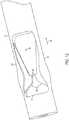
locking mechanism 101 is shown inFIG. 9 . Thelocking mechanism 101 is operable to adjustably secure theforceps tip 11. Thelocking mechanism 101 includes lockingmembers 106. In some instances, the lockingmembers 106 includemating teeth 108 that cooperatively engage with theteeth 39 of thetip connector 36 as illustrated inFIG. 8 . As shown inFIG. 8 , themating teeth 108 are adapted to engage the first and second set ofteeth tip connector 36. As theforceps tip 11 is moved in the direction ofarrow 49, theteeth 39 of the first and second sets ofteeth members 106. Particularly, as theteeth 39 move between the lockingmembers 106, the sloping surface of thefirst surface 47 of theteeth 39 causes the lockingmembers 106 to be deflected outwardly away from theforceps tip 11. As one of theteeth 39 extends past the ends of the lockingmembers 106, the lockingmembers 106 return to their initial positions. FIGS. 12 and13 illustratealternative locking mechanisms 101. Referring toFIG. 12 , theelongate member 96 defines aslot 97. Thelocking mechanism 101 includes lockingmembers 106 disposed in theslot 97. The lockingmembers 106 are integrally formed withwalls 107 defining theslot 97 and includemating teeth 108. Similar to those described above, themating teeth 108 are adapted to cooperatively engage withteeth 39 formed on theforceps tip 11. As the forceps tip 11 (not shown) is passed between the lockingmembers 106, theteeth 39 of theforceps tip 11 are operable to pass in the direction ofarrow 49 past themating teeth 108. As theteeth 39 pass themating teeth 108, theteeth 39 cause the lockingmember 106 to separate laterally. Thus, thewalls 107 flex in response to movement of theforceps tip 11 between the lockingmembers 106. Also similar to thelocking mechanism 101 shown inFIG. 8 , the lockingmembers 106 prevent movement of theforceps tip 11 in the direction opposite ofarrow 49 due to the interlocking fit betweenteeth 39 andmating teeth 108.- Referring to
FIG. 13 , again, theelongate member 96 defines aslot 97. The lockingmembers 106 protrude into theslot 97 and are adapted to engage theteeth 39 of theforceps tip 11 withmating teeth 108. The lockingmembers 106 are pivotably coupled to theelongate member 96 atbases 111. Each of the lockingmembers 106 is disposed in aslot 113. Theslots 113 may be formed perpendicular to theslot 97. Further, in some implementations, the lockingmembers 106 may be formed integrally with theelongate member 96. The lockingmembers 106 are adapted to flex laterally outwards as theteeth 39 of theforceps tip 11 pass themating teeth 108 when theforceps tip 11 is moved in the direction ofarrow 49. Similar to the lockingmembers 106 of thelocking mechanism 101 shown inFIGs. 8 and12 , the lockingmembers 106 are biased to return to their original position in response to movement of theteeth 39 andmating teeth 108 relative to each other. Also, interlocking of theteeth 39 andmating teeth 108 prevents movement of theforceps tip 11 relative to theelongate member 96 in the direction oppositearrow 49. - In their initial positions, the
second surface 48 of the teeth 39 (shown inFIG. 3 ) lockingly engage corresponding surfaces of theteeth 108, preventing movement of theforceps tip 11 in the direction of 49'. Consequently, thelocking mechanism 101 is adapted to permit movement of theforceps tip 11 in only one direction, i.e.,direction 49. As indicated above, in some implementations, theteeth 39 of the first and second sets ofteeth teeth 108 may similarly be offset by a distance S. Thus, in some implementations, as onetooth 39 of either the first set ofteeth 37 or the second set ofteeth 38 move past one of the lockingmembers 106 adjacent thereto, the interaction between one of theteeth 39 with theteeth 108 is operable to immobilize theforceps tip 11 within thedevice 200. Further, the offset distance S between the first and second sets ofteeth forceps tip 11, providing a more precise location of theforceps tip 11 within thedevice 200. This is particularly important in order to precisely locate thepincers 17 relative to thedistal end 55 of thesleeve 57. Precisely locating thepincers 17 relative to thesleeve 57 allows, for example, the pincers to be in their fully open configuration when thedevice pincers 17 towards each other when a user applies a force to urge thearm elements 73, is toward each other due to contact of thedistal end 55 of thesleeve 57 with thepincers 17. In some instances, positioning of theforceps tip 11 within thelocking mechanism 101 may be performed during assembly and fixed in place with an adhesive, for example. However, in other instances, theforceps tip 11 may be positioned within thelocking mechanism 101 at other times. - The locking
members 106 may also includeprotrusions 109. Theprotrusions 109 may be moved away from each other to release the forceps tip 11 from engagement with the lockingmembers 106. This may be useful if theforceps tip 11 has been positioned too far in the direction ofarrow 49. Separation of theprotrusions 109 and, hence, the lockingmembers 106 allows for theforceps tip 11 to be repositioned. For example, theforceps tip 11 may be moved in the position of arrow 49' upon separation of theprotrusions 109. - Referring to
FIGs. 2C and6 , operation of thedevice 200 is described. However, the described operation is also applicable to thedevice 100. In an at-rest condition, thepincers 17 of thedevice 200 are in a fully-open state. When thearm elements sleeve 57 andhub 86 are displaced in the direction ofarrow 58 via distal movement of ends of theresilient elements 88 that are coupled to thehub 86. Thedistal end 55 of thesleeve 57 engages thepincers 17, causing thetips 19 of thepincers 17 to move towards each other into a closed configuration. As thearm elements tips 19 are, accordingly, moved closer together. As a force applied to thearm elements arm elements resilient elements 88 displacesleeve 57 andhub 86 in the direction of arrow 58' relative to theforceps tip 11, causing thetips 19 to move away from each other due to the resilient properties of thepincer 17. Thepincers 17 continue to move away from each other until thearm elements - Referring to
FIGs. 6 and10 , thedevice 200 may include asleeve 150. Thesleeve 150 may be positioned over the interface between thelocking mechanism 101 and thetip connector 36 of theforceps tip 11. Additionally, thesleeve 150 may include a cam-shapedlip 152. The cam shape of thelip 152 defineslobes 115. Thelobes 115 may be positioned relative to one of thearm elements sleeve 150 aboutlongitudinal axis 114. Therim 152 and, particularly, thelobes 115 limit an amount of actuation of thedevice 200 as a result of contact between thearm elements rim 152. The amount of displacement of thearm elements rim 152 relative to thearm elements lobes 115 relative to thearm elements arm elements arm elements device 200. Consequently, a rotational position of therim 152 is operable to limit an amount by which thesleeve 57 is moved relative to theforceps tip 11. A position of thesleeve 150 may be selected during assembly of thedevice 200 or some other time. Further, thesleeve 150 may be fixed into place, for example, with an adhesive. While anexample sleeve 150 is shown with a pair oflobes 115,other sleeves 150 may have a different number oflobes 115. For example, anotherexample sleeve 150 may have asingle lobe 115. In other instances, thesleeve 150 may have more than twolobes 115. - Accordingly, it can be seen that the present disclosure provides for a forceps tip and, more generally, a forceps device that can be economically and efficiently mass produced from molded medical grade materials. The forceps device may be utilized in a capsulorhexis procedure. Further, the forceps device may be disposable after a single use. The forceps tip may also be easily and securely inserted into and removed from a handle of the forceps device, with the position of the forceps tip being adjustable with respect to the handle.
- The foregoing description generally illustrates and describes various implementations of the present disclosure. It will, however, be understood by those skilled in the art that various changes and modifications can be made to the above-discussed description without departing from the scope of the disclosure. It is intended that all matter contained in the above description or shown in the accompanying drawings shall be interpreted as being illustrative, and not to be taken in a limiting sense. Furthermore the scope of the present disclosure shall be construed to cover various modifications, combinations, additions, alterations, etc. above and to the above-described embodiments, which shall be considered to be within the scope of the present disclosure. Accordingly, various features and characteristics of the present disclosure as discussed herein may be selectively interchanged and applied to other illustrated and non-illustrated implementations, and numerous variations, modifications, and additions further can be made thereto without departing from the scope of the present disclosure as set forth in the appended claims.
Claims (15)
- A forceps device, comprising:a handle (12) comprising:a first arm element (73);a second arm element (74), the first arm element (73) and the second arm element (74) joined at a first end of the handle (12);an elongate body (96) extending between the first arm element (73) and the second arm element (74); anda locking mechanism (101) formed in the elongate body (96), the locking mechanism (101) comprising a first locking member (106) and a second locking member (106), the first locking member (106) and the second locking member (106) being laterally movable with respect to each other and with respect to a longitudinal axis (114) of the locking mechanism (101);a forceps tip (11) coupled to the handle (12), the forceps tip (11) comprising:a pair of pincers (17) extending from a distal end of the forceps tip (11), the pair of pincers (17) laterally offset from each other to define an open configuration and moveable between the open configuration and a closed configuration in which the pair of pincers (17) contact each other; anda tip connector (36) extending from a proximal end of the forceps tip (11), the tip connector (36) adapted to interlock with the locking mechanism (101); anda sleeve (57) coupled to the arm elements and defining a central passage, the forceps tip (11) extending through the central passage, the sleeve (57) operable to move relative to the forceps tip (11) and actuate the pincers (17) between the open configuration and the closed configuration in response to lateral displacement of the arm elements (73, 74);characterized in that :the tip connector (36) interlocks with the locking mechanism (101) such that when interlocked with the locking mechanism (101), the tip connector (36) is movable in a first axial direction (49) relative to the locking mechanism (101) and is prevented from moving in a second axial direction relative to the locking mechanism (101), the second axial direction being opposite the first axial direction.
- The forceps device of claim 1, further comprising resilient elements (88) extending between distal ends of the arm elements and the sleeve (57).
- The forceps device of claim 1, wherein a distal end of at least one of the pincers (17) comprises a grasping surface (22).
- The forceps device of claim 3, wherein the grasping surface comprises a series of serrations (29).
- The forceps device of claim 1, wherein the forceps tip (11) comprises a tip body (15), the tip body (15) including the pair of pincers (17), and a tip extension coupled to the tip body (15), the tip extension including the tip connector (36).
- The forceps device of claim 1, wherein the tip connector (36) comprises a first plurality of teeth (37, 38) arranged longitudinally along the forceps tip (11).
- The forceps device of claim 6, wherein the locking mechanism (101) comprises a second plurality of teeth (108), wherein the second plurality of teeth (108) are configured to interlock with the first plurality of teeth (37, 38) to couple the forceps tip (11) to the handle (12).
- The forceps device of claim 6, wherein the first plurality of teeth (37, 38) comprise:a first set of teeth (37) extending longitudinally along a first side (41) of the tip connector (36); anda second set of teeth (38) extending longitudinally along a second side (42) of the tip connector (36).
- The forceps device of claims 7 and 8, wherein the second plurality of teeth (108) comprises:a third set of teeth configured to interlock with the first set of teeth (37); anda fourth set of teeth configured to interlock with the second set of teeth (38).
- The forceps device of claim 8, wherein the first set of teeth (37) and the second set of teeth (38) are longitudinally offset from each other.
- The forceps device of claims 9 and 10, wherein the third set of teeth and the fourth set of teeth are offset from each other by the same amount the first set of teeth (37) is offset from the second set of teeth (38).
- The forceps device of claim 1, wherein the forceps tip (11) is formed from a plastic injection molded material.
- The forceps device of claim 1, wherein the forceps tip (11) is formed from a metal injection molded material.
- The forceps device of claim 1, wherein the locking mechanism (101) further comprises a third set of teeth formed on the first locking member (106) and a fourth set of teeth formed on the second locking member (106).
- The forceps tip (11) of claim 1, wherein the handle (12) further comprises:a first resilient element (88) extending between the first arm element (73) and the sleeve (57); anda second resilient element (88) extending between the second arm element (74) and the sleeve (57).
Applications Claiming Priority (2)
| Application Number | Priority Date | Filing Date | Title |
|---|---|---|---|
| US13/675,509US20140135820A1 (en) | 2012-11-13 | 2012-11-13 | Disposable capsulorhexis forceps |
| PCT/US2013/066575WO2014078049A1 (en) | 2012-11-13 | 2013-10-24 | Disposable capsulorhexis forceps |
Publications (3)
| Publication Number | Publication Date |
|---|---|
| EP2895079A1 EP2895079A1 (en) | 2015-07-22 |
| EP2895079A4 EP2895079A4 (en) | 2016-06-01 |
| EP2895079B1true EP2895079B1 (en) | 2017-06-21 |
Family
ID=50682420
Family Applications (1)
| Application Number | Title | Priority Date | Filing Date |
|---|---|---|---|
| EP13854303.8AActiveEP2895079B1 (en) | 2012-11-13 | 2013-10-24 | Disposable capsulorhexis forceps |
Country Status (12)
| Country | Link |
|---|---|
| US (1) | US20140135820A1 (en) |
| EP (1) | EP2895079B1 (en) |
| JP (1) | JP6258955B2 (en) |
| CN (1) | CN104994793B (en) |
| AR (1) | AR093432A1 (en) |
| AU (1) | AU2013345226B2 (en) |
| BR (1) | BR112015009874A2 (en) |
| CA (1) | CA2887000C (en) |
| ES (1) | ES2639169T3 (en) |
| RU (1) | RU2618178C9 (en) |
| TW (1) | TWI573555B (en) |
| WO (1) | WO2014078049A1 (en) |
Families Citing this family (40)
| Publication number | Priority date | Publication date | Assignee | Title |
|---|---|---|---|---|
| US9428254B1 (en) | 2010-09-24 | 2016-08-30 | Katalyst Surgical, Llc | Microsurgical handle and instrument |
| US8821444B2 (en) | 2011-10-03 | 2014-09-02 | Katalyst Surgical, Llc | Multi-utility surgical instrument |
| US9138346B2 (en) | 2012-01-26 | 2015-09-22 | Katalyst Surgical, Llc | Surgical instrument sleeve |
| US9629645B2 (en) | 2012-10-30 | 2017-04-25 | Katalyst Surgical, Llc | Atraumatic microsurgical forceps |
| US9226762B2 (en) | 2012-11-07 | 2016-01-05 | Katalyst Surgical, Llc | Atraumatic microsurgical forceps |
| US20140135820A1 (en) | 2012-11-13 | 2014-05-15 | Alcon Research, Ltd. | Disposable capsulorhexis forceps |
| US9320534B2 (en) | 2012-12-13 | 2016-04-26 | Alcon Research, Ltd. | Fine membrane forceps with integral scraping feature |
| US9204995B2 (en)* | 2013-03-12 | 2015-12-08 | Katalyst Surgical, Llc | Membrane removing forceps |
| US9827141B2 (en) | 2013-06-21 | 2017-11-28 | Novartis Ag | Systems and techniques for tissue manipulation during ocular surgery |
| US20150088193A1 (en)* | 2013-09-24 | 2015-03-26 | Katalyst Surgical, Llc | Membrane removing forceps |
| US10973682B2 (en)* | 2014-02-24 | 2021-04-13 | Alcon Inc. | Surgical instrument with adhesion optimized edge condition |
| US10022267B2 (en) | 2014-04-21 | 2018-07-17 | Katalyst Surgical, Llc | Method of manufacturing a microsurgical instrument tip |
| US20150342781A1 (en)* | 2014-05-29 | 2015-12-03 | Eitan Sobel | Apparatus for creating split incisions in a nucleus during cataract surgery. |
| US10406027B2 (en)* | 2014-06-13 | 2019-09-10 | Novartis Ag | OCT transparent surgical instruments and methods |
| US9775943B2 (en) | 2014-10-10 | 2017-10-03 | Katalyst Surgical, Llc | Cannula ingress system |
| US20160296246A1 (en)* | 2015-04-13 | 2016-10-13 | Novartis Ag | Forceps with metal and polymeric arms |
| CN104970918A (en)* | 2015-07-27 | 2015-10-14 | 浙江大学 | Microforceps used for posterior curvilinear capsulorhexis of sclera microincision posterior cataract |
| US20170079675A1 (en)* | 2015-09-18 | 2017-03-23 | Katalyst Surgical, Llc | Tapered membrane removing forceps |
| US10863998B2 (en)* | 2016-06-02 | 2020-12-15 | Merit Medical Systems, Inc. | Medical grasping device |
| KR101879504B1 (en)* | 2016-06-14 | 2018-07-17 | 아이 하스피틀, 웬조우 메디칼 유니버시티 | An anterior chamber irrigation maintainer |
| US11160935B2 (en) | 2016-06-16 | 2021-11-02 | Katalyst Surgical, Llc | Reusable instrument handle with single-use tip |
| TW201815356A (en) | 2016-10-18 | 2018-05-01 | 諾華公司 | Surgical instrument with surface texture |
| US10695043B2 (en) | 2017-02-21 | 2020-06-30 | Katalyst Surgical, Llc | Surgical instrument subcomponent integration by additive manufacturing |
| USD825755S1 (en)* | 2017-03-23 | 2018-08-14 | Karl Storz Gmbh & Co. Kg | Bipolar forceps |
| USD825058S1 (en)* | 2017-03-23 | 2018-08-07 | Karl Storz Gmbh & Co. Kg | Bipolar Forceps |
| USD825057S1 (en)* | 2017-03-23 | 2018-08-07 | Karl Storz Gmbh & Co. Kg | Bipolar forceps |
| USD825754S1 (en)* | 2017-03-23 | 2018-08-14 | Karl Storz Gmbh & Co. Kg | Bipolar forceps |
| US11224539B2 (en) | 2017-06-28 | 2022-01-18 | Alcon Inc. | Coated forceps for improved grasping |
| US20190038308A1 (en)* | 2017-08-02 | 2019-02-07 | Covidien Lp | Jaw members for surgical instruments and surgical instruments incorporating the same |
| EP3501433A1 (en)* | 2017-12-21 | 2019-06-26 | Universiteit Maastricht | Apparatus for handling a rod shaped element to be inserted into or removed from the eye of a patient |
| JP7432513B2 (en) | 2018-02-09 | 2024-02-16 | アルコン インコーポレイティド | Surgical tool mounting system and usage method |
| CN111867498A (en)* | 2018-03-29 | 2020-10-30 | 波士顿科学国际有限公司 | System and method for performing endoscopic surgery |
| US10849640B2 (en) | 2018-05-23 | 2020-12-01 | Katalyst Surgical, Llc | Membrane aggregating forceps |
| WO2020179550A1 (en) | 2019-03-06 | 2020-09-10 | マニー株式会社 | Ophthalmic tweezers |
| ES1232044Y (en)* | 2019-04-17 | 2019-09-26 | Simancas San Martin Beatriz | Metric dissection forceps |
| WO2021038428A1 (en)* | 2019-08-29 | 2021-03-04 | Alcon Inc. | Actuation mechanism with grooved actuation levers |
| JP7216630B2 (en) | 2019-09-26 | 2023-02-01 | マニー株式会社 | forceps for ophthalmology |
| USD886297S1 (en)* | 2019-10-17 | 2020-06-02 | Robert A. Van Wyk | Excising clamp assembly |
| US11719604B2 (en)* | 2020-07-16 | 2023-08-08 | Sakura Finetek U.S.A., Inc. | Forceps with replaceable tips |
| NL2029101B1 (en)* | 2021-09-01 | 2023-03-17 | Ophtec Bv | INTRAOCULAR LENS REMOVAL FOR THE REMOVAL OF AN INTRAOCULAR LENS (IOL), AND METHODS THEREOF |
Citations (15)
| Publication number | Priority date | Publication date | Assignee | Title |
|---|---|---|---|---|
| US5540530A (en) | 1993-04-28 | 1996-07-30 | Simpson Strong-Tie Company, Inc. | Self adjusting construction tie-down |
| WO1997015234A1 (en) | 1995-10-23 | 1997-05-01 | Johns Hopkins University | Surgical instrument |
| US5752960A (en) | 1996-05-31 | 1998-05-19 | Nallakrishnan; Ravi | Intraocular lens insertion forceps |
| US20010056286A1 (en) | 2000-10-19 | 2001-12-27 | Heinz Etter | Surgical instrument |
| US20030176890A1 (en) | 2002-02-04 | 2003-09-18 | Damage Control Surgical Technologies, Inc. | Method and apparatus for solid organ tissue approximation |
| US6730076B2 (en) | 2001-09-25 | 2004-05-04 | Alcon, Inc. | Fiberoptic probe tip |
| USD504176S1 (en) | 2002-12-11 | 2005-04-19 | D.O.R.C. Dutch Ophthalmic Research Center (International) B.V. | Tweezers |
| US20060036270A1 (en) | 2004-08-10 | 2006-02-16 | Asico Llc | Nucleus chopper and splitter |
| US20060184161A1 (en) | 2005-02-16 | 2006-08-17 | Usgi Medical Inc. | Flexible shaft system having interchangeable end effectors |
| US20080064929A1 (en) | 2006-09-09 | 2008-03-13 | Cardiomedical Gmbh | Medical instrument |
| US20090012519A1 (en) | 2007-07-03 | 2009-01-08 | Lisette Manrique | Electro-Surgical Bipolar Forceps |
| US20100168787A1 (en) | 2008-12-31 | 2010-07-01 | Wilson-Cook Medical Inc. | Medical device with pivotable jaws |
| US7758274B2 (en) | 2006-04-11 | 2010-07-20 | Warsaw Orthopedic, Inc. | Quick attachment apparatus for use in association with orthopedic instrumentation and tools |
| US8235978B2 (en) | 2007-11-01 | 2012-08-07 | Valens Associated Inc. | Thermal capsulotomy tool and system |
| WO2014078049A1 (en) | 2012-11-13 | 2014-05-22 | Alcon Research, Ltd. | Disposable capsulorhexis forceps |
Family Cites Families (18)
| Publication number | Priority date | Publication date | Assignee | Title |
|---|---|---|---|---|
| US4502186A (en)* | 1981-10-20 | 1985-03-05 | Blounthurst Limited | Clip for securing hosepipes and like uses |
| US4819972A (en)* | 1986-01-07 | 1989-04-11 | Gary Champa | Grip joints for plastic ducts |
| US5176700A (en)* | 1991-01-22 | 1993-01-05 | Pod, Inc. | Laparoscopic sponger-dissector forceps |
| JPH06292676A (en)* | 1993-04-12 | 1994-10-21 | Olympus Optical Co Ltd | Clamping pincers |
| US5501698A (en)* | 1994-02-14 | 1996-03-26 | Heartport, Inc. | Endoscopic microsurgical instruments and methods |
| US5893877A (en)* | 1996-04-10 | 1999-04-13 | Synergetics, Inc. | Surgical instrument with offset handle |
| US6089130A (en)* | 1999-06-01 | 2000-07-18 | Wu; Arthur | Adjustable wrench having weight reducing structure |
| US6488695B1 (en)* | 2000-08-17 | 2002-12-03 | Alcon, Inc. | Ophthalmologic surgical probe |
| US6945984B2 (en)* | 2001-08-23 | 2005-09-20 | Alcon Grieshaber Ag | Micro surgical instrument |
| US20050154375A1 (en)* | 2003-07-28 | 2005-07-14 | Innovatech Surgical, Inc. | Surgical instrument having a rotational ring |
| RU44490U1 (en)* | 2004-11-10 | 2005-03-27 | Уфимский научно-исследовательский институт глазных болезней | Tweezers for Phacofragmentation |
| JP4839035B2 (en)* | 2005-07-22 | 2011-12-14 | オリンパス株式会社 | Endoscopic treatment tool and endoscope system |
| US20080188877A1 (en)* | 2007-02-05 | 2008-08-07 | Hickingbotham Dyson W | Instruments For Removing an Object From the Eye |
| CN201743726U (en)* | 2010-06-18 | 2011-02-16 | 中国人民解放军第二军医大学 | No-damage kidney transplant internal iliac artery blocking clamp |
| RU101918U1 (en)* | 2010-08-04 | 2011-02-10 | Федеральное государственное учреждение "Межотраслевой научно-технический комплекс "Микрохирургия глаза" имени академика С.Н. Федорова Федерального агентства по высокотехнологичной медицинской помощи" | DEVICE FOR CIRCULAR CAPSULOREXIS FORMATION IN THROUGH KERATOPLASTICS AND ESTRAACapsULAR CATARACTS IN IOL IMPLANTATION |
| CN201996618U (en)* | 2011-03-14 | 2011-10-05 | 深圳市第二人民医院 | Cervical fixing and sealing pliers of uteroscope |
| US8840630B2 (en)* | 2011-06-15 | 2014-09-23 | Cook Medical Technologies Llc | Button release handle |
| US8806720B2 (en)* | 2012-01-24 | 2014-08-19 | Green Guard Industry Ltd. | Rack type telescopic handle of horticultural shears |
- 2012
- 2012-11-13USUS13/675,509patent/US20140135820A1/ennot_activeAbandoned
- 2013
- 2013-10-24AUAU2013345226Apatent/AU2013345226B2/enactiveActive
- 2013-10-24RURU2015122733Apatent/RU2618178C9/ennot_activeIP Right Cessation
- 2013-10-24CNCN201380055665.6Apatent/CN104994793B/enactiveActive
- 2013-10-24ESES13854303.8Tpatent/ES2639169T3/enactiveActive
- 2013-10-24BRBR112015009874Apatent/BR112015009874A2/ennot_activeApplication Discontinuation
- 2013-10-24EPEP13854303.8Apatent/EP2895079B1/enactiveActive
- 2013-10-24JPJP2015541797Apatent/JP6258955B2/enactiveActive
- 2013-10-24WOPCT/US2013/066575patent/WO2014078049A1/enactiveApplication Filing
- 2013-10-24CACA2887000Apatent/CA2887000C/enactiveActive
- 2013-10-31TWTW102139533Apatent/TWI573555B/ennot_activeIP Right Cessation
- 2013-11-11ARARP130104129Apatent/AR093432A1/enunknown
Patent Citations (15)
| Publication number | Priority date | Publication date | Assignee | Title |
|---|---|---|---|---|
| US5540530A (en) | 1993-04-28 | 1996-07-30 | Simpson Strong-Tie Company, Inc. | Self adjusting construction tie-down |
| WO1997015234A1 (en) | 1995-10-23 | 1997-05-01 | Johns Hopkins University | Surgical instrument |
| US5752960A (en) | 1996-05-31 | 1998-05-19 | Nallakrishnan; Ravi | Intraocular lens insertion forceps |
| US20010056286A1 (en) | 2000-10-19 | 2001-12-27 | Heinz Etter | Surgical instrument |
| US6730076B2 (en) | 2001-09-25 | 2004-05-04 | Alcon, Inc. | Fiberoptic probe tip |
| US20030176890A1 (en) | 2002-02-04 | 2003-09-18 | Damage Control Surgical Technologies, Inc. | Method and apparatus for solid organ tissue approximation |
| USD504176S1 (en) | 2002-12-11 | 2005-04-19 | D.O.R.C. Dutch Ophthalmic Research Center (International) B.V. | Tweezers |
| US20060036270A1 (en) | 2004-08-10 | 2006-02-16 | Asico Llc | Nucleus chopper and splitter |
| US20060184161A1 (en) | 2005-02-16 | 2006-08-17 | Usgi Medical Inc. | Flexible shaft system having interchangeable end effectors |
| US7758274B2 (en) | 2006-04-11 | 2010-07-20 | Warsaw Orthopedic, Inc. | Quick attachment apparatus for use in association with orthopedic instrumentation and tools |
| US20080064929A1 (en) | 2006-09-09 | 2008-03-13 | Cardiomedical Gmbh | Medical instrument |
| US20090012519A1 (en) | 2007-07-03 | 2009-01-08 | Lisette Manrique | Electro-Surgical Bipolar Forceps |
| US8235978B2 (en) | 2007-11-01 | 2012-08-07 | Valens Associated Inc. | Thermal capsulotomy tool and system |
| US20100168787A1 (en) | 2008-12-31 | 2010-07-01 | Wilson-Cook Medical Inc. | Medical device with pivotable jaws |
| WO2014078049A1 (en) | 2012-11-13 | 2014-05-22 | Alcon Research, Ltd. | Disposable capsulorhexis forceps |
Non-Patent Citations (2)
| Title |
|---|
| EIDESSTATTLICHE VERSICHERUNG - WIRD NACHGEREICHT |
| HANS GEUDER, AUGENINSTRUMENTE, pages 17 |
Also Published As
| Publication number | Publication date |
|---|---|
| CA2887000A1 (en) | 2014-05-22 |
| AU2013345226A1 (en) | 2015-04-23 |
| EP2895079A1 (en) | 2015-07-22 |
| TW201434431A (en) | 2014-09-16 |
| ES2639169T3 (en) | 2017-10-25 |
| CA2887000C (en) | 2017-04-04 |
| WO2014078049A1 (en) | 2014-05-22 |
| BR112015009874A2 (en) | 2017-07-11 |
| CN104994793A (en) | 2015-10-21 |
| RU2618178C9 (en) | 2017-08-18 |
| US20140135820A1 (en) | 2014-05-15 |
| RU2618178C2 (en) | 2017-05-02 |
| JP6258955B2 (en) | 2018-01-10 |
| EP2895079A4 (en) | 2016-06-01 |
| AR093432A1 (en) | 2015-06-10 |
| CN104994793B (en) | 2018-02-09 |
| JP2015534857A (en) | 2015-12-07 |
| RU2015122733A (en) | 2017-01-10 |
| TWI573555B (en) | 2017-03-11 |
| AU2013345226B2 (en) | 2016-10-27 |
Similar Documents
| Publication | Publication Date | Title |
|---|---|---|
| EP2895079B1 (en) | Disposable capsulorhexis forceps | |
| US12115104B2 (en) | Devices and methods for ocular surgery | |
| AU2020200023B2 (en) | Devices and methods for the removal of lenticular tissue | |
| US7011666B2 (en) | Incising apparatus for use in cataract surgery | |
| AU720114B2 (en) | Deformable intraocular lens injecting device | |
| US6605093B1 (en) | Device and method for use with an ophthalmologic insertor apparatus | |
| EP2490597B1 (en) | Speculum | |
| EP2768407B1 (en) | Trocar system | |
| WO1996028122A9 (en) | Deformable intraocular lens injecting device | |
| US12426905B2 (en) | Wound visualization forceps and method | |
| WO2020157617A1 (en) | Actuation mechanism with arcuate levers | |
| EP2444007A1 (en) | Stitch-removal pincer | |
| WO2000040175A1 (en) | Apparatus for insertion of an intraocular lens | |
| US6299617B1 (en) | Instrument for fixating the eye during cataract surgery | |
| CN115484878A (en) | Bone punching instrument | |
| RU2783788C2 (en) | Devices for eye surgery | |
| JP2008307297A (en) | Anterior capsulotomy knife |
Legal Events
| Date | Code | Title | Description |
|---|---|---|---|
| PUAI | Public reference made under article 153(3) epc to a published international application that has entered the european phase | Free format text:ORIGINAL CODE: 0009012 | |
| 17P | Request for examination filed | Effective date:20150409 | |
| AK | Designated contracting states | Kind code of ref document:A1 Designated state(s):AL AT BE BG CH CY CZ DE DK EE ES FI FR GB GR HR HU IE IS IT LI LT LU LV MC MK MT NL NO PL PT RO RS SE SI SK SM TR | |
| AX | Request for extension of the european patent | Extension state:BA ME | |
| DAX | Request for extension of the european patent (deleted) | ||
| RA4 | Supplementary search report drawn up and despatched (corrected) | Effective date:20160503 | |
| RIC1 | Information provided on ipc code assigned before grant | Ipc:A61B 17/00 20060101AFI20160426BHEP Ipc:A61B 17/28 20060101ALI20160426BHEP Ipc:A61B 17/30 20060101ALI20160426BHEP Ipc:A61B 17/29 20060101ALI20160426BHEP Ipc:A61F 9/00 20060101ALI20160426BHEP Ipc:A61F 9/007 20060101ALI20160426BHEP | |
| GRAP | Despatch of communication of intention to grant a patent | Free format text:ORIGINAL CODE: EPIDOSNIGR1 | |
| STAA | Information on the status of an ep patent application or granted ep patent | Free format text:STATUS: GRANT OF PATENT IS INTENDED | |
| RIC1 | Information provided on ipc code assigned before grant | Ipc:A61B 17/29 20060101ALI20170222BHEP Ipc:A61B 17/00 20060101AFI20170222BHEP Ipc:A61F 9/007 20060101ALI20170222BHEP Ipc:A61B 17/30 20060101ALI20170222BHEP | |
| INTG | Intention to grant announced | Effective date:20170308 | |
| GRAS | Grant fee paid | Free format text:ORIGINAL CODE: EPIDOSNIGR3 | |
| GRAA | (expected) grant | Free format text:ORIGINAL CODE: 0009210 | |
| STAA | Information on the status of an ep patent application or granted ep patent | Free format text:STATUS: THE PATENT HAS BEEN GRANTED | |
| AK | Designated contracting states | Kind code of ref document:B1 Designated state(s):AL AT BE BG CH CY CZ DE DK EE ES FI FR GB GR HR HU IE IS IT LI LT LU LV MC MK MT NL NO PL PT RO RS SE SI SK SM TR | |
| REG | Reference to a national code | Ref country code:GB Ref legal event code:FG4D | |
| REG | Reference to a national code | Ref country code:CH Ref legal event code:EP | |
| REG | Reference to a national code | Ref country code:IE Ref legal event code:FG4D | |
| REG | Reference to a national code | Ref country code:AT Ref legal event code:REF Ref document number:902220 Country of ref document:AT Kind code of ref document:T Effective date:20170715 | |
| REG | Reference to a national code | Ref country code:DE Ref legal event code:R096 Ref document number:602013022701 Country of ref document:DE | |
| REG | Reference to a national code | Ref country code:FR Ref legal event code:PLFP Year of fee payment:5 | |
| REG | Reference to a national code | Ref country code:ES Ref legal event code:FG2A Ref document number:2639169 Country of ref document:ES Kind code of ref document:T3 Effective date:20171025 Ref country code:NL Ref legal event code:MP Effective date:20170621 | |
| PG25 | Lapsed in a contracting state [announced via postgrant information from national office to epo] | Ref country code:HR Free format text:LAPSE BECAUSE OF FAILURE TO SUBMIT A TRANSLATION OF THE DESCRIPTION OR TO PAY THE FEE WITHIN THE PRESCRIBED TIME-LIMIT Effective date:20170621 Ref country code:FI Free format text:LAPSE BECAUSE OF FAILURE TO SUBMIT A TRANSLATION OF THE DESCRIPTION OR TO PAY THE FEE WITHIN THE PRESCRIBED TIME-LIMIT Effective date:20170621 Ref country code:NO Free format text:LAPSE BECAUSE OF FAILURE TO SUBMIT A TRANSLATION OF THE DESCRIPTION OR TO PAY THE FEE WITHIN THE PRESCRIBED TIME-LIMIT Effective date:20170921 Ref country code:LT Free format text:LAPSE BECAUSE OF FAILURE TO SUBMIT A TRANSLATION OF THE DESCRIPTION OR TO PAY THE FEE WITHIN THE PRESCRIBED TIME-LIMIT Effective date:20170621 Ref country code:GR Free format text:LAPSE BECAUSE OF FAILURE TO SUBMIT A TRANSLATION OF THE DESCRIPTION OR TO PAY THE FEE WITHIN THE PRESCRIBED TIME-LIMIT Effective date:20170922 | |
| REG | Reference to a national code | Ref country code:LT Ref legal event code:MG4D | |
| REG | Reference to a national code | Ref country code:AT Ref legal event code:MK05 Ref document number:902220 Country of ref document:AT Kind code of ref document:T Effective date:20170621 | |
| PG25 | Lapsed in a contracting state [announced via postgrant information from national office to epo] | Ref country code:BG Free format text:LAPSE BECAUSE OF FAILURE TO SUBMIT A TRANSLATION OF THE DESCRIPTION OR TO PAY THE FEE WITHIN THE PRESCRIBED TIME-LIMIT Effective date:20170921 Ref country code:LV Free format text:LAPSE BECAUSE OF FAILURE TO SUBMIT A TRANSLATION OF THE DESCRIPTION OR TO PAY THE FEE WITHIN THE PRESCRIBED TIME-LIMIT Effective date:20170621 Ref country code:RS Free format text:LAPSE BECAUSE OF FAILURE TO SUBMIT A TRANSLATION OF THE DESCRIPTION OR TO PAY THE FEE WITHIN THE PRESCRIBED TIME-LIMIT Effective date:20170621 Ref country code:SE Free format text:LAPSE BECAUSE OF FAILURE TO SUBMIT A TRANSLATION OF THE DESCRIPTION OR TO PAY THE FEE WITHIN THE PRESCRIBED TIME-LIMIT Effective date:20170621 Ref country code:NL Free format text:LAPSE BECAUSE OF FAILURE TO SUBMIT A TRANSLATION OF THE DESCRIPTION OR TO PAY THE FEE WITHIN THE PRESCRIBED TIME-LIMIT Effective date:20170621 | |
| PG25 | Lapsed in a contracting state [announced via postgrant information from national office to epo] | Ref country code:SK Free format text:LAPSE BECAUSE OF FAILURE TO SUBMIT A TRANSLATION OF THE DESCRIPTION OR TO PAY THE FEE WITHIN THE PRESCRIBED TIME-LIMIT Effective date:20170621 Ref country code:RO Free format text:LAPSE BECAUSE OF FAILURE TO SUBMIT A TRANSLATION OF THE DESCRIPTION OR TO PAY THE FEE WITHIN THE PRESCRIBED TIME-LIMIT Effective date:20170621 Ref country code:CZ Free format text:LAPSE BECAUSE OF FAILURE TO SUBMIT A TRANSLATION OF THE DESCRIPTION OR TO PAY THE FEE WITHIN THE PRESCRIBED TIME-LIMIT Effective date:20170621 Ref country code:EE Free format text:LAPSE BECAUSE OF FAILURE TO SUBMIT A TRANSLATION OF THE DESCRIPTION OR TO PAY THE FEE WITHIN THE PRESCRIBED TIME-LIMIT Effective date:20170621 Ref country code:AT Free format text:LAPSE BECAUSE OF FAILURE TO SUBMIT A TRANSLATION OF THE DESCRIPTION OR TO PAY THE FEE WITHIN THE PRESCRIBED TIME-LIMIT Effective date:20170621 | |
| PG25 | Lapsed in a contracting state [announced via postgrant information from national office to epo] | Ref country code:SM Free format text:LAPSE BECAUSE OF FAILURE TO SUBMIT A TRANSLATION OF THE DESCRIPTION OR TO PAY THE FEE WITHIN THE PRESCRIBED TIME-LIMIT Effective date:20170621 Ref country code:PL Free format text:LAPSE BECAUSE OF FAILURE TO SUBMIT A TRANSLATION OF THE DESCRIPTION OR TO PAY THE FEE WITHIN THE PRESCRIBED TIME-LIMIT Effective date:20170621 Ref country code:IS Free format text:LAPSE BECAUSE OF FAILURE TO SUBMIT A TRANSLATION OF THE DESCRIPTION OR TO PAY THE FEE WITHIN THE PRESCRIBED TIME-LIMIT Effective date:20171021 | |
| REG | Reference to a national code | Ref country code:DE Ref legal event code:R026 Ref document number:602013022701 Country of ref document:DE | |
| PLBI | Opposition filed | Free format text:ORIGINAL CODE: 0009260 | |
| PLAX | Notice of opposition and request to file observation + time limit sent | Free format text:ORIGINAL CODE: EPIDOSNOBS2 | |
| PG25 | Lapsed in a contracting state [announced via postgrant information from national office to epo] | Ref country code:DK Free format text:LAPSE BECAUSE OF FAILURE TO SUBMIT A TRANSLATION OF THE DESCRIPTION OR TO PAY THE FEE WITHIN THE PRESCRIBED TIME-LIMIT Effective date:20170621 | |
| 26 | Opposition filed | Opponent name:GEUDER AG Effective date:20180321 | |
| PG25 | Lapsed in a contracting state [announced via postgrant information from national office to epo] | Ref country code:MC Free format text:LAPSE BECAUSE OF FAILURE TO SUBMIT A TRANSLATION OF THE DESCRIPTION OR TO PAY THE FEE WITHIN THE PRESCRIBED TIME-LIMIT Effective date:20170621 | |
| REG | Reference to a national code | Ref country code:CH Ref legal event code:PL | |
| REG | Reference to a national code | Ref country code:IE Ref legal event code:MM4A | |
| PG25 | Lapsed in a contracting state [announced via postgrant information from national office to epo] | Ref country code:CH Free format text:LAPSE BECAUSE OF NON-PAYMENT OF DUE FEES Effective date:20171031 Ref country code:LI Free format text:LAPSE BECAUSE OF NON-PAYMENT OF DUE FEES Effective date:20171031 Ref country code:LU Free format text:LAPSE BECAUSE OF NON-PAYMENT OF DUE FEES Effective date:20171024 | |
| PLBB | Reply of patent proprietor to notice(s) of opposition received | Free format text:ORIGINAL CODE: EPIDOSNOBS3 | |
| REG | Reference to a national code | Ref country code:BE Ref legal event code:MM Effective date:20171031 | |
| PG25 | Lapsed in a contracting state [announced via postgrant information from national office to epo] | Ref country code:SI Free format text:LAPSE BECAUSE OF FAILURE TO SUBMIT A TRANSLATION OF THE DESCRIPTION OR TO PAY THE FEE WITHIN THE PRESCRIBED TIME-LIMIT Effective date:20170621 Ref country code:BE Free format text:LAPSE BECAUSE OF NON-PAYMENT OF DUE FEES Effective date:20171031 | |
| PG25 | Lapsed in a contracting state [announced via postgrant information from national office to epo] | Ref country code:MT Free format text:LAPSE BECAUSE OF NON-PAYMENT OF DUE FEES Effective date:20171024 | |
| REG | Reference to a national code | Ref country code:FR Ref legal event code:PLFP Year of fee payment:6 | |
| PG25 | Lapsed in a contracting state [announced via postgrant information from national office to epo] | Ref country code:IE Free format text:LAPSE BECAUSE OF NON-PAYMENT OF DUE FEES Effective date:20171024 | |
| PG25 | Lapsed in a contracting state [announced via postgrant information from national office to epo] | Ref country code:HU Free format text:LAPSE BECAUSE OF FAILURE TO SUBMIT A TRANSLATION OF THE DESCRIPTION OR TO PAY THE FEE WITHIN THE PRESCRIBED TIME-LIMIT; INVALID AB INITIO Effective date:20131024 | |
| PLCK | Communication despatched that opposition was rejected | Free format text:ORIGINAL CODE: EPIDOSNREJ1 | |
| REG | Reference to a national code | Ref country code:DE Ref legal event code:R100 Ref document number:602013022701 Country of ref document:DE | |
| PG25 | Lapsed in a contracting state [announced via postgrant information from national office to epo] | Ref country code:CY Free format text:LAPSE BECAUSE OF FAILURE TO SUBMIT A TRANSLATION OF THE DESCRIPTION OR TO PAY THE FEE WITHIN THE PRESCRIBED TIME-LIMIT Effective date:20170621 | |
| PLBN | Opposition rejected | Free format text:ORIGINAL CODE: 0009273 | |
| STAA | Information on the status of an ep patent application or granted ep patent | Free format text:STATUS: OPPOSITION REJECTED | |
| PG25 | Lapsed in a contracting state [announced via postgrant information from national office to epo] | Ref country code:MK Free format text:LAPSE BECAUSE OF FAILURE TO SUBMIT A TRANSLATION OF THE DESCRIPTION OR TO PAY THE FEE WITHIN THE PRESCRIBED TIME-LIMIT Effective date:20170621 | |
| 27O | Opposition rejected | Effective date:20190819 | |
| REG | Reference to a national code | Ref country code:GB Ref legal event code:732E Free format text:REGISTERED BETWEEN 20200109 AND 20200115 | |
| REG | Reference to a national code | Ref country code:GB Ref legal event code:732E Free format text:REGISTERED BETWEEN 20200116 AND 20200122 | |
| REG | Reference to a national code | Ref country code:DE Ref legal event code:R081 Ref document number:602013022701 Country of ref document:DE Owner name:ALCON INC., CH Free format text:FORMER OWNER: ALCON RESEARCH, LTD., 76134-2099 FORT WORTH, TEXAS, US | |
| PG25 | Lapsed in a contracting state [announced via postgrant information from national office to epo] | Ref country code:TR Free format text:LAPSE BECAUSE OF FAILURE TO SUBMIT A TRANSLATION OF THE DESCRIPTION OR TO PAY THE FEE WITHIN THE PRESCRIBED TIME-LIMIT Effective date:20170621 | |
| REG | Reference to a national code | Ref country code:ES Ref legal event code:PC2A Owner name:ALCON INC. Effective date:20200407 | |
| PG25 | Lapsed in a contracting state [announced via postgrant information from national office to epo] | Ref country code:PT Free format text:LAPSE BECAUSE OF FAILURE TO SUBMIT A TRANSLATION OF THE DESCRIPTION OR TO PAY THE FEE WITHIN THE PRESCRIBED TIME-LIMIT Effective date:20170621 | |
| PG25 | Lapsed in a contracting state [announced via postgrant information from national office to epo] | Ref country code:AL Free format text:LAPSE BECAUSE OF FAILURE TO SUBMIT A TRANSLATION OF THE DESCRIPTION OR TO PAY THE FEE WITHIN THE PRESCRIBED TIME-LIMIT Effective date:20170621 | |
| P01 | Opt-out of the competence of the unified patent court (upc) registered | Effective date:20230505 | |
| PGFP | Annual fee paid to national office [announced via postgrant information from national office to epo] | Ref country code:GB Payment date:20240919 Year of fee payment:12 | |
| PGFP | Annual fee paid to national office [announced via postgrant information from national office to epo] | Ref country code:FR Payment date:20240923 Year of fee payment:12 | |
| PGFP | Annual fee paid to national office [announced via postgrant information from national office to epo] | Ref country code:IT Payment date:20240926 Year of fee payment:12 | |
| PGFP | Annual fee paid to national office [announced via postgrant information from national office to epo] | Ref country code:DE Payment date:20240925 Year of fee payment:12 | |
| PGFP | Annual fee paid to national office [announced via postgrant information from national office to epo] | Ref country code:ES Payment date:20241105 Year of fee payment:12 |