EP2895048B1 - Sensing system - Google Patents
Sensing systemDownload PDFInfo
- Publication number
- EP2895048B1 EP2895048B1EP13837832.8AEP13837832AEP2895048B1EP 2895048 B1EP2895048 B1EP 2895048B1EP 13837832 AEP13837832 AEP 13837832AEP 2895048 B1EP2895048 B1EP 2895048B1
- Authority
- EP
- European Patent Office
- Prior art keywords
- eyelid
- contact lens
- sensors
- sensor
- covered
- Prior art date
- Legal status (The legal status is an assumption and is not a legal conclusion. Google has not performed a legal analysis and makes no representation as to the accuracy of the status listed.)
- Active
Links
- 210000000744eyelidAnatomy0.000claimsdescription106
- 238000000034methodMethods0.000claimsdescription40
- 238000012545processingMethods0.000claimsdescription21
- 239000000758substrateSubstances0.000claimsdescription5
- 238000001514detection methodMethods0.000description36
- 230000000193eyeblinkEffects0.000description31
- 230000000670limiting effectEffects0.000description30
- 238000010586diagramMethods0.000description26
- 230000004397blinkingEffects0.000description21
- 238000003860storageMethods0.000description18
- 230000000875corresponding effectEffects0.000description12
- 238000004891communicationMethods0.000description9
- 230000003993interactionEffects0.000description9
- 230000036961partial effectEffects0.000description9
- 230000008569processEffects0.000description8
- 230000008859changeEffects0.000description7
- 230000006870functionEffects0.000description6
- 230000009471actionEffects0.000description4
- 230000008901benefitEffects0.000description4
- 238000012706support-vector machineMethods0.000description4
- 230000008878couplingEffects0.000description3
- 238000010168coupling processMethods0.000description3
- 238000005859coupling reactionMethods0.000description3
- 230000007246mechanismEffects0.000description3
- 239000002609mediumSubstances0.000description3
- 230000003213activating effectEffects0.000description2
- 238000004458analytical methodMethods0.000description2
- 238000013528artificial neural networkMethods0.000description2
- 230000005540biological transmissionEffects0.000description2
- 238000013461designMethods0.000description2
- 238000009826distributionMethods0.000description2
- 238000005516engineering processMethods0.000description2
- 230000033001locomotionEffects0.000description2
- 238000007726management methodMethods0.000description2
- 238000007620mathematical functionMethods0.000description2
- 238000012544monitoring processMethods0.000description2
- 241000282472Canis lupus familiarisSpecies0.000description1
- 239000004606Fillers/ExtendersSubstances0.000description1
- 206010041349SomnolenceDiseases0.000description1
- 238000007792additionMethods0.000description1
- 238000013459approachMethods0.000description1
- 239000003990capacitorSubstances0.000description1
- 230000001413cellular effectEffects0.000description1
- 238000013145classification modelMethods0.000description1
- 150000001875compoundsChemical class0.000description1
- 238000010276constructionMethods0.000description1
- 230000001276controlling effectEffects0.000description1
- 230000002596correlated effectEffects0.000description1
- 238000003066decision treeMethods0.000description1
- 238000002405diagnostic procedureMethods0.000description1
- 230000005684electric fieldEffects0.000description1
- 230000004927fusionEffects0.000description1
- 239000011521glassSubstances0.000description1
- 230000036541healthEffects0.000description1
- 230000002452interceptive effectEffects0.000description1
- 210000000554irisAnatomy0.000description1
- 238000004519manufacturing processMethods0.000description1
- 239000000463materialSubstances0.000description1
- 238000012986modificationMethods0.000description1
- 230000004048modificationEffects0.000description1
- 230000003287optical effectEffects0.000description1
- 230000002093peripheral effectEffects0.000description1
- 230000004962physiological conditionEffects0.000description1
- 210000001747pupilAnatomy0.000description1
- 230000002829reductive effectEffects0.000description1
- 230000035945sensitivityEffects0.000description1
- 241000894007speciesSpecies0.000description1
- 230000003068static effectEffects0.000description1
- 239000000126substanceSubstances0.000description1
- 230000002123temporal effectEffects0.000description1
- 238000012360testing methodMethods0.000description1
- 238000012549trainingMethods0.000description1
- 238000012546transferMethods0.000description1
- 230000007704transitionEffects0.000description1
- 230000007723transport mechanismEffects0.000description1
- 239000006163transport mediaSubstances0.000description1
- 230000002747voluntary effectEffects0.000description1
Images


Classifications
- A—HUMAN NECESSITIES
- A61—MEDICAL OR VETERINARY SCIENCE; HYGIENE
- A61B—DIAGNOSIS; SURGERY; IDENTIFICATION
- A61B5/00—Measuring for diagnostic purposes; Identification of persons
- A61B5/103—Measuring devices for testing the shape, pattern, colour, size or movement of the body or parts thereof, for diagnostic purposes
- A61B5/11—Measuring movement of the entire body or parts thereof, e.g. head or hand tremor or mobility of a limb
- A61B5/1103—Detecting muscular movement of the eye, e.g. eyelid movement
- A—HUMAN NECESSITIES
- A61—MEDICAL OR VETERINARY SCIENCE; HYGIENE
- A61B—DIAGNOSIS; SURGERY; IDENTIFICATION
- A61B3/00—Apparatus for testing the eyes; Instruments for examining the eyes
- A61B3/10—Objective types, i.e. instruments for examining the eyes independent of the patients' perceptions or reactions
- A61B3/113—Objective types, i.e. instruments for examining the eyes independent of the patients' perceptions or reactions for determining or recording eye movement
- A—HUMAN NECESSITIES
- A61—MEDICAL OR VETERINARY SCIENCE; HYGIENE
- A61B—DIAGNOSIS; SURGERY; IDENTIFICATION
- A61B5/00—Measuring for diagnostic purposes; Identification of persons
- A61B5/68—Arrangements of detecting, measuring or recording means, e.g. sensors, in relation to patient
- A61B5/6801—Arrangements of detecting, measuring or recording means, e.g. sensors, in relation to patient specially adapted to be attached to or worn on the body surface
- A61B5/6813—Specially adapted to be attached to a specific body part
- A61B5/6814—Head
- A61B5/6821—Eye
- G—PHYSICS
- G02—OPTICS
- G02C—SPECTACLES; SUNGLASSES OR GOGGLES INSOFAR AS THEY HAVE THE SAME FEATURES AS SPECTACLES; CONTACT LENSES
- G02C7/00—Optical parts
- G02C7/02—Lenses; Lens systems ; Methods of designing lenses
- G02C7/04—Contact lenses for the eyes
- A—HUMAN NECESSITIES
- A61—MEDICAL OR VETERINARY SCIENCE; HYGIENE
- A61B—DIAGNOSIS; SURGERY; IDENTIFICATION
- A61B2503/00—Evaluating a particular growth phase or type of persons or animals
- A61B2503/20—Workers
- A61B2503/22—Motor vehicles operators, e.g. drivers, pilots, captains
Definitions
- This disclosuregenerally relates to systems and methods for employing multiple sensors on a contact lens for detecting blinks and contact lens orientation.
- US2003/0021601 A1discloses a system of the present invention automatically controls electronic devices on physiological conditions of a user.
- US2001/0028309 A1discloses apparatus for monitoring movement of a person's eye, e.g., to monitor drowsiness.
- WO2012/05223 A2discloses techniques, systems and apparatus for implementing a telescopic contact lens.
- US2011/0084834 A1discloses a method for tracking ophthalmic lens care compliance.
- a first devicemay be provided.
- the first devicemay include a first lens that comprises a contact lens or an intraocular lens.
- US2003/0069489 A1discloses utilization of a contact device placed on the front part of the eye in order to detect physical and chemical parameters of the body as well as the non-invasive delivery of compounds.
- WO2011/067391 A1discloses the invention relates to the electrically controlled focusing ophthalmic device to be worn by a user.
- the present inventionprovides a device as set out in claim 1. Further aspects of the present invention are set out in the remaining claims.
- a mechanismfor detecting blinking of an eye via multiple sensors on or within the contact lens (hereinafter referred to as multi-sensor contact lens).
- a multi-sensor contact lenscan be placed in one or both eyes of a user that can actively determine (or infer) blinking of the eye.
- multi-sensor contact lensmonitors sensors on or within the multi-sensor contact lens at intervals that are less than an average or shortest length of time of an eye blink. It is to be appreciated that both eyes of a human user generally blink at the same time, and thus in various embodiments only one multi-sensor contact lens is needed.
- two such multi-sensor contact lensescan be employed such that a user can selectively blink one or both eyes, for example to generate a command to a remote device.
- the multi-sensor contact lenscan be employed in connection with non-human users (e.g., dogs or other species with eyes).
- detected (or inferred) blinkingcan include determination or inference of full or partial eye blinks. It is to be appreciated that components on or within a contact lens can be of a shape, size, opacity, and/or positioned so as not to obstruct vision through an opening of a pupil of an eye when worn.
- a mechanismfor detecting orientation of a multi-sensor contact lens.
- a multi-sensor contact lenscan be placed in one or both eyes of a user that can actively determine (or infer) their respective orientations.
- multi-sensor contact lensmonitors sensors on or within the multi-sensor contact lens and based upon an order which they enter a state indicative of being covered or uncovered by an eyelid, determines (or infers) orientation of the multi-sensor contact lens.
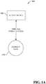
- FIG. 1Adepicts a system 100 for detecting (or inferring) eye blinking or contact lens orientation using a multi-sensor contact lens.
- System 100includes a multi-sensor contact lens 110 that determines (or infers) blinking of an eye on which the multi-sensor contacts lens is worn or orientation of the multi-sensor contact lens.
- multi-sensor contact lens 110can utilize information regarding the determined (or inferred) blinking of the eye (hereinafter referred to as "eye blink information") or orientation of the multi-sensor contact lens (hereinafter referred to as "orientation information”) locally to control features of multi-sensor contact lens 110 (e.g., issuing commands, adjusting content presentation, activating or deactivating options or components, or any other suitable function).
- eye blink informationinformation regarding the determined (or inferred) blinking of the eye
- orientation informationorientation of the multi-sensor contact lens
- multi-sensor contact lens 110can optionally communicate eye blink information and/or orientation information to a remote device 120 for employment in connection with operations associated with the remote device 120 (e.g., adjusting content presentation, controlling a user interface, activating or deactivating options or components, requesting instructions or information, issuing commands, or any other suitable function).
- Multi-sensor contact lens 110 and remote device 120can also receive input from users, for example to control interaction with and presentation of content, see e.g., FIG. 8 and corresponding disclosure.
- Multi-sensor contact lens 110 and remote device 120respectively include a memory that stores computer executable components and a processor that executes computer executable components stored in the memory (see e.g., FIG. 8 ).
- Multi-sensor contact lens 110 and remote device 120can communicate via a wireless network. It is to be appreciated that while only one remote device 120 is depicted, multi-sensor contact lens 110 can communicate with any suitable number of remote devices 120 concurrently, serially, an ad hoc manner, or in accordance with any suitable protocol. Additionally, remote device 120 can communicate with any suitable number of multi-sensor contact lenses 110 concurrently, serially, an ad hoc manner, or in accordance with any suitable protocol.
- Remote device 120can include a wearable device or a non-wearable device.
- Wearable devicecan include, for example, heads-up display glasses, a monocle, eyeglasses, sunglasses, a headset, a visor, a cap, a helmet, a mask, a headband, clothing, or any other suitable device that can be worn by a human or non-human user and can communicate with multi-sensor contact lens 110 remotely.
- Non-wearable devicecan include, for example, a mobile device, a mobile phone, a camera, a camcorder, a video camera, personal data assistant, laptop computer, tablet computer, desktop computer, server system, cable set top box, satellite set top box, cable modem, television set, monitor, media extender device, blu-ray device, DVD (digital versatile disc or digital video disc) device, compact disc device, video game system, portable video game console, audio/video receiver, radio device, portable music player, navigation system, car stereo, or any suitable device that can communicate with multi-sensor contact lens 110 remotely.
- a mobile devicea mobile phone, a camera, a camcorder, a video camera, personal data assistant, laptop computer, tablet computer, desktop computer, server system, cable set top box, satellite set top box, cable modem, television set, monitor, media extender device, blu-ray device, DVD (digital versatile disc or digital video disc) device, compact disc device, video game system, portable video game console, audio/video receiver, radio device, portable music player, navigation system
- remote device 120 and multi-sensor contact lens 110can include a display and/or user interface (e.g., a web browser or application), that can generate, receive and/or present graphical indicia (e.g., displays, text, video%) generated locally or remotely.
- a display and/or user interfacee.g., a web browser or application
- graphical indiciae.g., displays, text, video
- system 100is depicted on a human user.
- Multi-sensor contact lenses 110are shown worn on both eyes 130, covering irises 140 while eyelids 150 are open.
- Remote device 120is shown with one or more transceivers (not shown) arranged to communicate wirelessly with multi-sensor contact lenses 110. It is to be further appreciated that respective transceivers of remote device 120 can have transmission power and/or signal reception sensitivity suitable for transmitting a signal to and receiving a signal from an associated multi-sensor contact lenses 110 on an eye without interfering with another multi-sensor contact lenses 110 on another eye. While FIG. 1B depicts a multi-sensor contact lenses 110 arrangement in both eyes, it is to be appreciated that an arrangement with a multi-sensor contact lens 110 on one eye can be employed.
- multi-sensor contact lens 110is depicted that includes, disposed on or within its substrate, a control circuit 220 and two or more sensors 230 (in this example, four sensors 230 equally spaced around the periphery of multi-sensor contact lens 110).
- Control circuit 220 and sensors 230are coupled wirelessly or via wire by coupling 240.
- all or some sensors 230can have independent coupling to control circuit 220.
- different aspects of interaction between control circuit 220 and sensors 230may be respectively coupled via wire or wirelessly. In one example, all interactions are coupled via wire. In another example, all interactions are coupled wirelessly. In a further example, some interactions are coupled wirelessly, while other interactions are coupled via wire.
- Sensor 230can be any suitable sensor that changes state based on a condition that changes according to sensor 230 being covered or uncovered by eyelid 150 during blinking of eye 130.
- sensor 230can be a photodiode that changes state based upon an amount of light received at the photodiode, such as difference in amount of light incident on the photodiode when an eyelid 150 covers the photodiode versus not covering the photodiode.
- sensor 230can be a pressure sensor that changes state according to pressure change caused by an eyelid 150 covering or uncovering sensor 230.
- sensor 230can be a conductivity sensor that changes state according to changes in conductivity from a tear film caused by an eyelid 150 covering or uncovering sensor 230.
- sensor 230can be a temperature sensor that changes state according to a change in temperature as a tear film caused by an eyelid 150 covering or uncovering sensor 230 evaporates.
- sensor 230can be an electric field sensor that changes state according changes in static charge or capacitance caused by an eyelid 150 covering or uncovering sensor 230. It is to be appreciated that sensors 230 can respectively be uniquely identifiable to control circuit 220, for example, via an identifier signal or identifying information conveyed from respective sensors 230 to control circuit 220.
- multi-sensor contact lens 110can be weighted to self-align into a particular position when worn, similar to toric contact lenses.
- sensors 230may require specific positioning in order to detect eye blinks.
- multi-sensor contact lens 110are not weighted.
- sufficient sensors 230can be employed in an arrangement, such as four sensors 230 equally spaced around a periphery of multi-sensor contact lens 110 to detect a blink in most any orientation of the multi-sensor contact lens 110.
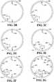
- FIG. 2Bshows a multi-sensor contact lens 110 with two sensors 230 respectively aligned at top and bottom of multi-sensor contact lens 110.
- FIG. 2Cdepicts a multi-sensor contact lens 110 with two sensors respectively aligned at a bottom and one side of multi-sensor contact lens 110.
- FIG. 2Ddepicts a multi-sensor contact lens 110 with three sensors 230 respectively aligned at top, bottom, and one side of multi-sensor contact lens 110.
- FIG. 2Eillustrates a multi-sensor contact lens 110 with three sensors 230 aligned in an equilateral triangular shape near the periphery of multi-sensor contact lens 110.
- FIG. 2Fdepicts a multi-sensor contact lens 110 with five sensors 230 aligned in a pentagon shape near the periphery of multi-sensor contact lens 110.
- FIG. 2Gillustrates a multi-sensor contact lens 110 with eight sensors 230 aligned in a regular octagon shape near the periphery of multi-sensor contact lens 110.
- Employing a plurality of uniquely identifiable sensors 230allows for detecting partial eye blinks or an amount of eye blink, and orientation of the multi-sensor contact lens 110 as discussed below. It is to be appreciated that any suitable number of sensors 230 can be respectively placed in any suitable locations of multi-sensor contact lens 110.
- increasing number of sensors 230for example distributed around the periphery of the multi-sensor contact lens 110 or linearly across one or more portions of the multi-sensor contact lens 110, can increase precision or granularity of determining (or inferring) an amount of eye blink or orientation of the multi-sensor contact lens 110.
- control circuit 220that includes processing component 255 that determines (or infers) blinking of an eye, orientation of multi-sensor contact lens 110, and communicates with remote device 120 and sensors 230.
- control circuit 220can include power component 275 that manages, receives, generates, stores, and/or distributes electrical power to other components of multi-sensor contact lens 110.
- Control circuit 220can also include one or more transceivers 280 for transmitting or receiving signals to or from remote device 120 or sensors 230. It is to be appreciated that sensors 230 can interface directly with processing component 255 without need to employ transceiver 280, for example through a wired coupling.
- control circuit 220can include a data store 250 that can store data from processing component 255, power component 275, transceiver 280, remote device 120, or sensors 230.
- Data store 250can reside on any suitable type of storage device, non-limiting examples of which are illustrated with reference to FIGS. 7 and 8 , and corresponding disclosure.
- processing component 255includes blink detection component 260 that determines (or infers) blinking of an eye based upon state information from sensors 230 indicative of being covered or uncovered by eyelid 150. It is to be appreciated that blink detection component 260 can pull state information from sensors 230 or can automatically have state information pushed by sensors 230. It is further to be appreciated that blink detection component 260 can determine (or infer) state information based upon signals or information received from sensors 230. In an embodiment, blink detection component 260 can continuously monitor sensors 230. In another embodiment, blink detection component 260 can periodically monitor sensors 230.
- blink detection component 260can monitor sensors 230 at intervals that are less than an average or shortest length of time of an eye blink to avoid missing detection of a blink. For example, if the average human user has a blink that is N milliseconds, blink detection component 260 can monitor sensors 230 at an interval less than N milliseconds. In another example, if the shortest blink for a human user is M milliseconds, blink detection component 260 can monitor sensors 230 at an interval less than M milliseconds. It is to be appreciated that any suitable interval for monitoring sensors 230 can be employed.
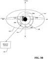
- FIG. 3Ais depicted a close-up of FIG. 1B of a portion of eye 130 wearing a multi-sensor contact lens 110 with four sensors in a configuration as illustrated in FIG. 2A equally spaced around the periphery of multi-sensor contact lens 110.
- respective sensors 230A-Dare uniquely identifiable to blink detection component 260.
- the four sensors 230are oriented with sensors 230B and 230D aligned on a horizontal axis X and sensors 230A and 230C aligned on a vertical axis Y.
- Axis X and Yhave an origin at the geometric center of multi-sensor contact lens 110.
- eyelid 150is open.
- blink detection component 260obtains state information corresponding to sensors 230A-D not being covered by eyelid 150.
- FIG. 3Bcorresponds to FIG. 3A with eyelid 150 partially closed.
- blink detection component 260obtains state information corresponding to sensor 230A covered by eyelid 150 and sensors 230B-D not covered by eyelid 150.
- FIG. 3Ccorresponds to FIGs. 3A-B with eyelid 150 partially closed an amount more than depicted in FIG. 3B .
- blink detection component 260obtains state information corresponding to sensors 230A-B and 230D being covered by eyelid 150 and sensor 230C not being covered by eyelid 150.
- state informationcan allow blink detection component 260 to determine (or infer) amount of partial blink that has occurred based on known or inferred positioning, for example using a coordinate system based upon the X and Y axis, of sensors 230A-D relative to each other or to a fixed position, such the geometric center of the multi-sensor contact lens 110.
- FIG. 3Dcorresponds to FIGs. 3A-C with eyelid 150 closed.
- blink detection component 260obtains state information corresponding to sensors 230A-D being covered by eyelid 150.
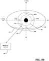
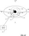
- FIG. 4Acorresponds to figure 3A with the multi-sensor contact lens 110 oriented at an angle of rotation a number of degrees about its geometric center. Eyelid 150 is open, and as such, blink detection component 260 obtains state information corresponding to sensors 230A-D not being covered by eyelid 150.
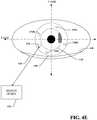
- FIG. 4Bcorresponds to FIG. 4A with eyelid 150 partially closed.
- blink detection component 260obtains state information corresponding to sensor 230A covered by eyelid 150 and sensors 230B-D not covered by eyelid 150.
- FIG. 4Ccorresponds to FIGs. 4A-B with eyelid 150 partially closed an amount more than depicted in FIG. 4B .
- blink detection component 260obtains state information corresponding to sensors 230A-B being covered by eyelid 150 and sensors 230C-D not being covered by eyelid 150.
- FIG. 4Dcorresponds to FIGs. 4A-C with eyelid 150 partially closed an amount more than depicted in FIG. 4C .
- blink detection component 260obtains state information corresponding to sensors 230A-B and 230D being covered by eyelid 150 and sensor 230C not being covered by eyelid 150.
- the rotated orientation of multi-sensor contact lensallows for a finer precision or granularity with respect to determining (or inferring) the amount of partial blink that has occurred based on known or inferred positioning of sensors 230A-D.
- FIG. 4Ecorresponds to FIGs. 4A-D with eyelid 150 closed.
- blink detection component 260obtains state information corresponding to sensors 230A-D being covered by eyelid 150.
- FIGs 3A-D and 4A-Eare non-limiting examples of configurations for sensors on multi-sensor contact lens 110. It is to be appreciated that any suitable number sensors 230 can be placed in any suitable location(s) of multi-sensor contact lens 110. It is to be further appreciated that, respective multi-sensor contact lens 110 in two eyes can have differing configurations of sensors 230.
- Blink detection component 260employs the state information to determine (or infer) a blink of eye 130. It is to be appreciated that blink detection component 260 can employ various algorithms and mathematical functions to determine eye blink information. In an embodiment, blink detection component 260 or sensor 230 can determine state information by employing data from sensor 230 in conjunction with a threshold to determined (or inferred) whether eyelid 150 is covering sensor 230. It is to be appreciated that a threshold can be any condition, for example, a greater than condition, less than condition, equal to condition, one or more ranges, or function. For example, if data from sensor 230 is below or equal to an eyelid covering threshold, it can be determined (or inferred) that eyelid 150 is covering sensor 230.
- blink detection component 260can employ state information obtained at multiple points in time to determine duration of eyelid 150 covering sensor 230.
- Blink detection component 260can employ duration of eyelid closure over a period of time, for example at consecutive points in time indicating eyelid closure, to determine whether a blink has occurred or whether the eyelid is closed, for example, during a nap.
- Blink detection component 260can employ an eyelid closure duration threshold to indicate whether a blink has occurred.
- blink detection component 260can track the respective times that respective sensors 230 indicate a state change indicating covering or uncovering by eyelid 150 during a single eye blink along with known positions of the respective sensors 230 to determine a speed at which the eye blink occurred.
- Blink detection component 260can employ speed at which an eye blink occurred, for example, to determine (or infer) an involuntary eye blink versus a voluntary eye blink, such as when a user is selectively blinking. Additionally, blink detection component 260 can employ an order in which sensors 230 are covered or uncovered to determine (or infer) an eye blink. For example, if a sensor 230 indicates a state change that is not in alignment with an expected order or state changes for sensors 230 during an eye blink, blink detection component can determine (or infer) that an eye blink did not occur, such during a faulty sensor reading or a sensor 230 being covered by something other than an eyelid.
- blink detection component 260can track eye blinks over a period of time to identify patterns of eye blinking for one or both eyes. It is to be appreciated that pattern of eye blinking can include number of blinks in one or both eyes, duration of blinks in one or both eyes, pause between blinks in one or both eyes, partial blinks (an amount of partial blink) in one or both eyes, order of blinks in one or both eyes, or speed of eye blink.
- blink detection component 260can identify a known pattern of blinking for one or both eyes that correlates to an associated command input, from a library of commands, of the multi-sensor contact lens 110 or remote device 120.
- a library of commandscan include one or more commands with a respective pattern of eye blinking that corresponds to a respective command.
- interface component 270can communicate eye blink information, such as a determined (or inferred) blink of an eye, speed of an eye blink, an identified pattern of eye blinking, command input associated with an identified pattern of eye blinking, or respective times or order that respective sensors 230 indicate a state change indicating covering or uncovering by eyelid 150, to remote device 120 using one or more transceivers 280.
- eye blink informationsuch as a determined (or inferred) blink of an eye, speed of an eye blink, an identified pattern of eye blinking, command input associated with an identified pattern of eye blinking, or respective times or order that respective sensors 230 indicate a state change indicating covering or uncovering by eyelid 150
- eye blink informationsuch as a determined (or inferred) blink of an eye, speed of an eye blink, an identified pattern of eye blinking, command input associated with an identified pattern of eye blinking, or respective times or order that respective sensors 230 indicate a state change indicating covering or uncovering by eyelid 150
- interface component 270can receive data or commands from remote device 120 using the
- Orientation component 265can employ eye blink information to determine (or infer) orientation of a multi-sensor contact lens 110 when worn in an eye. It is to be appreciated that orientation component 265 can employ various algorithms and mathematical functions to determine orientation information. For example, the order that respective sensors 230 indicate a state change indicating covering or uncovering by eyelid 150 can allow for determining (or inferring) rotational orientation of multi-sensor contact lens 110 about its geometric center. Referring to FIGS. 3A-D , sensor 230A is covered first as eyelid 150 closes during a blink, then next sensors 230B and 230D are covered substantially simultaneously, and then sensor 230C is covered, and visa-versa as eyelid 150 opens.
- this orderingcan provide an indication that sensor 230A is oriented above sensors 230B-D, and that sensors 230B and 230D are aligned parallel to the X axis below sensor 230A and above sensor 230C.
- Orientation component 265can employ this information to determine (or infer) that multi-sensor contact lens 110 is oriented as depicted in FIGS 3A-D . Referring to FIGs 4A-E , sensor 230A is covered first as eyelid 150 blinks, then sensor 230B is covered, followed by sensor 230D, and then sensor 230C is covered, and visa-versa as eyelid 150 opens.
- this orderingcan provide an indication that sensor 230A is oriented above sensors 230B, which is oriented above sensor 230D, which is oriented above sensor 230C.
- Orientation component 265can employ this information to determine (or infer) that multi-sensor contact lens 110 is oriented as depicted in FIGS 4A-E , within a window of error.
- the window of errorcan be, for example, a rotational angle window surrounding a sensor 230 within which multi-sensor contact lens 110 can rotate about its geometric center while sensor 230 remains above or below a neighboring sensor 230.
- this window of errorcan be reduced as density of sensors increases on or within multi-sensor contact lens 110, for example, distributed around the periphery of the multi-sensor contact lens 110 or linearly across one or more portions of the multi-sensor contact lens 110. It is further to be appreciated that a partial blink covering at least two sensors 230 can be sufficient to determine (or infer) orientation of multi-sensor contact lens 110 within a window of error.
- orientation component 265can employ a predetermined blink speed indicative of the speed at which eyelid 150 moves along the Y axis during an eye blink to increase precision of estimation of position of two sensors 230 relative to each other and the geometric center of multi-sensor contact lens 110.
- the predetermined blink speedcan be an average speed of a human user or non-human user eye blink.
- the predetermined blink speedcan be determined as part of a calibration operation of multi-sensor contact lens 110 when worn in an eye 130. It is to be appreciated that predetermined blink speed can be based upon any suitable mechanism for setting, determining, or inferring speed of an eye blink.
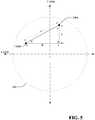
- multi-sensor contact lens 110with two sensors 230A-B worn in eye 130.
- distance Acan be determined (or inferred) by orientation component 265.
- distance Ccan be determined (or inferred) by orientation component 265.
- angle Dknown to be a 90 degree angle
- distance B and angles E and Fcan be determined (or inferred) by orientation component 265.
- orientation component 265can determine (or infer) the positions of sensor 230A-B relative to the X and Y axis having an origin at the geometric center of multi-sensor contact lens 110. It is to be appreciated that orientation information can include determined (or inferred) positions of sensors 230 relative to a coordinate system, a rotational angle of multi-sensor contact lens 110 about its geometric center, or any other suitable indication for orientation of multi-sensor contact lens 110. Additionally, orientation information can be included in eye blink information. Interface component 270 can communicate orientation information to remote device 120.
- multi-sensor contact lens 110 or remote device 120can employ orientation information to send commands to or interpret data from one or more components (shown or not shown) of multi-sensor contact lens 110.
- multi-sensor contact lens 110can have one or more LEDs (not shown) visible to a user when worn that have specific meaning based upon their position in the user's view. Orientation information can be employed to control which LEDs to activate.
- multi-sensor contact lens 110can have a display (not shown) visible to the user when worn. Orientation information can be employed to control presentation of content, for example, to maintain a properly oriented display.
- user health diagnostic componentssuch as a camera directed to the interior of the eye, may require specific positioning or need to be interpreted differently based upon position. Orientation information can allow for determination of the reliability of diagnostic data or when to initiate a diagnostic test.
- Power component 275can include any suitable power source that can manage, receive, generate, store, and/or distribute necessary electrical power for the operation of various components of multi-sensor contact lens 110.
- power component 275can include but is not limited to a battery, a capacitor, a solar power source, radio frequency power source, electrochemical power source, temperature power source, or mechanically derived power source (e.g., MEMs system).
- power component 275receives or generates power from one or more sensors 230.
- Transceiver 280can transmit and receive information to and from, or within multi-sensor contact lens 110.
- transceiver 280can include an RF antenna.
- userscan opt-in or opt-out of providing personal information, demographic information, location information, proprietary information, sensitive information, or the like in connection with data gathering aspects.
- one or more implementations described hereincan provide for anonymizing collected, received, or transmitted data.
- FIG. 6illustrates various methodologies in accordance with certain disclosed aspects. While, for purposes of simplicity of explanation, the methodologies are shown and described as a series of acts, it is to be understood and appreciated that the disclosed aspects are not limited by the order of acts, as some acts may occur in different orders and/or concurrently with other acts from that shown and described herein. For example, those skilled in the art will understand and appreciate that a methodology can alternatively be represented as a series of interrelated states or events, such as in a state diagram. Moreover, not all illustrated acts may be required to implement a methodology in accordance with certain disclosed aspects. Additionally, it is to be further appreciated that the methodologies disclosed hereinafter and throughout this disclosure are capable of being stored on an article of manufacture to facilitate transporting and transferring such methodologies to computers.
- an exemplary method 600 for determining blinking of an eye or orientation of a contact lensis depicted.
- state information related to sensors of a multi-sensor contact lens(es) worn in one or more eyesis obtained (e.g. by blink detection component 260, sensor 230, or control circuit 220).
- one or more full or partial blinks of the one or more eyesis determined (or inferred) based on the state information (e.g. by a blink detection component 260 or control circuit 220).
- an optional act of identifying a pattern of blinking of the one or more eyesis performed (e.g. by a blink detection component 260 or control circuit 220).
- an optional act of determining a command input associated with the identified pattern of eye blinkingis performed (e.g. by a blink detection component 260 or control circuit 220).
- an optional act of determining (or inferring) orientation information for the multi-sensor contact lens(es) worn in one or more eyes based upon the determined (or inferred) full or partial blink or eye blink information derived therefromis performed (e.g. by an orientation component 265 or control circuit 220).
- an optional act of communicating eye blink or orientation information to a remote deviceis performed (e.g. by an interface component 270 or control circuit 220).
- the various embodiments described hereincan be implemented in connection with any computer or other client or server device, which can be deployed as part of a computer network or in a distributed computing environment, and can be connected to any kind of data store where media may be found.
- the various embodiments described hereincan be implemented in any computer system or environment having any number of memory or storage units, and any number of applications and processes occurring across any number of storage units. This includes, but is not limited to, an environment with server computers and client computers deployed in a network environment or a distributed computing environment, having remote or local storage.
- Distributed computingprovides sharing of computer resources and services by communicative exchange among computing devices and systems. These resources and services include the exchange of information, cache storage and disk storage for objects, such as files. These resources and services can also include the sharing of processing power across multiple processing units for load balancing, expansion of resources, specialization of processing, and the like. Distributed computing takes advantage of network connectivity, allowing clients to leverage their collective power to benefit the entire enterprise. In this regard, a variety of devices may have applications, objects or resources that may participate in the various embodiments of this disclosure.
- Fig. 7provides a schematic diagram of an exemplary networked or distributed computing environment.
- the distributed computing environmentcomprises computing objects 710, 712, etc. and computing objects or devices 720, 722, 724, 726, 728, etc., which may include programs, methods, data stores, programmable logic, etc., as represented by applications 730, 732, 734, 736, 738.
- computing objects 710, 712, etc. and computing objects or devices 720, 722, 724, 726, 728, etc.may comprise different devices, such as personal digital assistants (PDAs), audio/video devices, mobile phones, MP3 players, personal computers, laptops, tablets, etc.
- PDAspersonal digital assistants
- Each computing object 710, 712, etc. and computing objects or devices 720, 722, 724, 726, 728, etc.can communicate with one or more other computing objects 710, 712, etc. and computing objects or devices 720, 722, 724, 726, 728, etc. by way of the communications network 740, either directly or indirectly.
- network 740may comprise other computing objects and computing devices that provide services to the system of Fig. 7 , and/or may represent multiple interconnected networks, which are not shown.
- Each computing object 710, 712, etc. or computing objects or devices 720, 722, 724, 726, 728, etc.can also contain an application, such as applications 730, 732, 734, 736, 738, that might make use of an API, or other object, software, firmware and/or hardware, suitable for communication with or implementation of various embodiments of this disclosure.
- computing systemscan be connected together by wired or wireless systems, by local networks or widely distributed networks.
- networksare coupled to the Internet, which provides an infrastructure for widely distributed computing and encompasses many different networks, though any suitable network infrastructure can be used for exemplary communications made incident to the systems as described in various embodiments herein.
- client/serverpeer-to-peer
- hybrid architecturesa host of network topologies and network infrastructures, such as client/server, peer-to-peer, or hybrid architectures.
- the "client”is a member of a class or group that uses the services of another class or group.
- a clientcan be a computer process, e.g., roughly a set of instructions or tasks, that requests a service provided by another program or process.
- a client processmay utilize the requested service without having to "know" all working details about the other program or the service itself.
- a clientcan be a computer that accesses shared network resources provided by another computer, e.g., a server.
- a servere.g., a server
- computing objects or devices 720, 722, 724, 726, 728, etc.can be thought of as clients and computing objects 710, 712, etc. can be thought of as servers where computing objects 710, 712, etc.
- any computercan be considered a client, a server, or both, depending on the circumstances. Any of these computing devices may be processing data, or requesting transaction services or tasks that may implicate the techniques for systems as described herein for one or more embodiments.
- a serveris typically a remote computer system accessible over a remote or local network, such as the Internet or wireless network infrastructures.
- the client processmay be active in a first computer system, and the server process may be active in a second computer system, communicating with one another over a communications medium, thus providing distributed functionality and allowing multiple clients to take advantage of the information-gathering capabilities of the server.
- Any software objects utilized pursuant to the techniques described hereincan be provided standalone, or distributed across multiple computing devices or objects.
- the computing objects 710, 712, etc.can be Web servers, file servers, media servers, etc. with which the client computing objects or devices 720, 722, 724, 726, 728, etc. communicate via any of a number of known protocols, such as the hypertext transfer protocol (HTTP).
- HTTPhypertext transfer protocol
- Objects 710, 712, etc.may also serve as client computing objects or devices 720, 722, 724, 726, 728, etc., as may be characteristic of a distributed computing environment.
- a suitable servercan include one or more aspects of the below computer, such as a media server or other media management server components.
- embodimentscan partly be implemented via an operating system, for use by a developer of services for a device or object, and/or included within application software that operates to perform one or more functional aspects of the various embodiments described herein.
- Softwaremay be described in the general context of computer executable instructions, such as program modules, being executed by one or more computers, such as client workstations, servers or other devices.
- computerssuch as client workstations, servers or other devices.
- client workstationssuch as client workstations, servers or other devices.
- Fig. 8thus illustrates an example of a suitable computing system environment 800 in which one or aspects of the embodiments described herein can be implemented, although as made clear above, the computing system environment 800 is only one example of a suitable computing environment and is not intended to suggest any limitation as to scope of use or functionality. Neither is the computing environment 800 be interpreted as having any dependency or requirement relating to any one or combination of components illustrated in the exemplary operating environment 800.
- FIG. 8an exemplary computing device for implementing one or more embodiments in the form of a computer 810 is depicted.
- Components of computer 810may include, but are not limited to, a processing unit 820, a system memory 830, and a system bus 822 that couples various system components including the system memory to the processing unit 820.
- Computer 810typically includes a variety of computer readable media and can be any available media that can be accessed by computer 810.
- the system memory 830may include computer storage media in the form of volatile and/or nonvolatile memory such as read only memory (ROM) and/or random access memory (RAM).
- system memory 830may also include an operating system, application programs, other program modules, and program data.
- a usercan enter commands and information into the computer 810 through input devices 840, non-limiting examples of which can include a keyboard, keypad, a pointing device, a mouse, stylus, touchpad, touchscreen, trackball, motion detector, camera, microphone, joystick, game pad, scanner, or any other device that allows the user to interact with computer 810.
- input devices 840non-limiting examples of which can include a keyboard, keypad, a pointing device, a mouse, stylus, touchpad, touchscreen, trackball, motion detector, camera, microphone, joystick, game pad, scanner, or any other device that allows the user to interact with computer 810.
- a monitor or other type of display deviceis also connected to the system bus 822 via an interface, such as output interface 850.
- computerscan also include other peripheral output devices such as speakers and a printer, which may be connected through output interface 850.
- the computer 810may operate in a networked or distributed environment using logical connections to one or more other remote computers, such as remote computer 860.
- the remote computer 860may be a personal computer, a server, a router, a network PC, a peer device or other common network node, or any other remote media consumption or transmission device, and may include any or all of the elements described above relative to the computer 810.
- the logical connections depicted in Fig. 8include a network 862, such local area network (LAN) or a wide area network (WAN), but may also include other networks/buses e.g., cellular networks.
- an appropriate APIe.g., an appropriate API, tool kit, driver code, operating system, control, standalone or downloadable software object, etc. which enables applications and services to take advantage of the techniques described herein.
- embodiments hereinare contemplated from the standpoint of an API (or other software object), as well as from a software or hardware object that implements one or more aspects described herein.
- various embodiments described hereincan have aspects that are wholly in hardware, partly in hardware and partly in software, as well as in software.
- Computer-readable storage mediacan be any available storage media that can be accessed by the computer, is typically of a non-transitory nature, and can include both volatile and nonvolatile media, removable and non-removable media.
- Computer-readable storage mediacan be implemented in connection with any method or technology for storage of information such as computer-readable instructions, program modules, structured data, or unstructured data.
- Computer-readable storage mediacan include, but are not limited to, RAM, ROM, EEPROM, flash memory or other memory technology, CD-ROM, digital versatile disk (DVD) or other optical disk storage, magnetic cassettes, magnetic tape, magnetic disk storage or other magnetic storage devices, or other tangible and/or non-transitory media which can be used to store desired information.
- Computer-readable storage mediacan be accessed by one or more local or remote computing devices, e.g., via access requests, queries or other data retrieval protocols, for a variety of operations with respect to the information stored by the medium.
- communications mediatypically embody computer-readable instructions, data structures, program modules or other structured or unstructured data in a data signal such as a modulated data signal, e.g., a carrier wave or other transport mechanism, and includes any information delivery or transport media.
- modulated data signalor signals refers to a signal that has one or more of its characteristics set or changed in such a manner as to encode information in one or more signals.
- communication mediainclude wired media, such as a wired network or direct-wired connection, and wireless media such as acoustic, RF, infrared and other wireless media.
- a componentmay be, but is not limited to being, a process running on a processor, a processor, an object, an executable, a thread of execution, a program, and/or a computer.
- an application running on computer and the computercan be a component.
- One or more componentsmay reside within a process and/or thread of execution and a component may be localized on one computer and/or distributed between two or more computers.
- a “device”can come in the form of specially designed hardware; generalized hardware made specialized by the execution of software thereon that enables the hardware to perform specific function (e.g., coding and/or decoding); software stored on a computer readable medium; or a combination thereof.
- components described hereincan examine the entirety or a subset of the data to which it is granted access and can provide for reasoning about or infer states of the system, environment, etc. from a set of observations as captured via events and/or data.
- Inferencecan be employed to identify a specific context or action, or can generate a probability distribution over states, for example.
- the inferencecan be probabilistic - that is, the computation of a probability distribution over states of interest based on a consideration of data and events.
- Inferencecan also refer to techniques employed for composing higher-level events from a set of events and/or data.
- Such inferencecan result in the construction of new events or actions from a set of observed events and/or stored event data, whether or not the events are correlated in close temporal proximity, and whether the events and data come from one or several event and data sources.
- Various classification (explicitly and/or implicitly trained) schemes and/or systemse.g ., support vector machines, neural networks, expert systems, Bayesian belief networks, fuzzy logic, data fusion engines, etc.
- support vector machines, neural networks, expert systems, Bayesian belief networks, fuzzy logic, data fusion engines, etc.can be employed in connection with performing automatic and/or inferred action in connection with the claimed subject matter.
- Such classificationcan employ a probabilistic and/or statistical-based analysis (e.g -., factoring into the analysis utilities and costs) to prognose or infer an action that a user desires to be automatically performed.
- a support vector machine (SVM)is an example of a classifier that can be employed. The SVM operates by finding a hyper-surface in the space of possible inputs, where the hyper-surface attempts to split the triggering criteria from the non-triggering events.
- Other directed and undirected model classification approachesinclude, e.g., na ⁇ ve Bayes, Bayesian networks, decision trees, neural networks, fuzzy logic models, and probabilistic classification models providing different patterns of independence can be employed. Classification as used herein also is inclusive of statistical regression that is utilized to develop models of priority.
Landscapes
- Health & Medical Sciences (AREA)
- Life Sciences & Earth Sciences (AREA)
- Ophthalmology & Optometry (AREA)
- Physics & Mathematics (AREA)
- General Health & Medical Sciences (AREA)
- Engineering & Computer Science (AREA)
- Medical Informatics (AREA)
- Public Health (AREA)
- Veterinary Medicine (AREA)
- Biomedical Technology (AREA)
- Heart & Thoracic Surgery (AREA)
- Biophysics (AREA)
- Molecular Biology (AREA)
- Surgery (AREA)
- Animal Behavior & Ethology (AREA)
- Pathology (AREA)
- General Physics & Mathematics (AREA)
- Optics & Photonics (AREA)
- Physiology (AREA)
- Dentistry (AREA)
- Oral & Maxillofacial Surgery (AREA)
- Human Computer Interaction (AREA)
- Eyeglasses (AREA)
- Measurement Of The Respiration, Hearing Ability, Form, And Blood Characteristics Of Living Organisms (AREA)
- User Interface Of Digital Computer (AREA)
- Light Receiving Elements (AREA)
- Geophysics And Detection Of Objects (AREA)
Description
- This disclosure generally relates to systems and methods for employing multiple sensors on a contact lens for detecting blinks and contact lens orientation.
US2003/0021601 A1 discloses a system of the present invention automatically controls electronic devices on physiological conditions of a user.US2001/0028309 A1 discloses apparatus for monitoring movement of a person's eye, e.g., to monitor drowsiness.WO2012/05223 A2 US2011/0084834 A1 discloses a method for tracking ophthalmic lens care compliance.US2012/0140167 A1 discloses in some embodiments, a first device may be provided. The first device may include a first lens that comprises a contact lens or an intraocular lens.US2003/0069489 A1 discloses utilization of a contact device placed on the front part of the eye in order to detect physical and chemical parameters of the body as well as the non-invasive delivery of compounds.WO2011/067391 A1 discloses the invention relates to the electrically controlled focusing ophthalmic device to be worn by a user.- The present invention provides a device as set out in claim 1. Further aspects of the present invention are set out in the remaining claims.
Figure 1A illustrates a diagram of an exemplary non-limiting system for system for detecting eye blinking or contact lens orientation using a multi-sensor contact lens in accordance with an implementation of this disclosure.Figure 1B illustrates a diagram of the exemplary non-limiting system ofFigure 1A worn on both eyes of a human user in accordance with an implementation of this disclosure.Figure 2A illustrates a diagram of an exemplary non-limiting multi-sensor contact lens accordance with an implementation of this disclosure.Figure 2B illustrates a diagram of an exemplary non-limiting multi-sensor contact lens with two sensors respectively aligned at top and bottom of multi-sensor contact lens in accordance with an implementation of this disclosure.Figure 2C illustrates a diagram of an exemplary non-limiting multi-sensor contact lens with two sensors respectively aligned at a bottom and one side of multi-sensor contact lens in accordance with an implementation of this disclosure.Figure 2D illustrates a diagram of an exemplary non-limiting multi-sensor contact lens with three sensors respectively aligned at top, bottom, and one side of multi-sensor contact lens in accordance with an implementation of this disclosure.Figure 2E illustrates a diagram of an exemplary non-limiting multi-sensor contact lens with three sensors aligned in an equilateral triangular shape near the periphery of multi-sensor contact lens in accordance with an implementation of this disclosure.Figure 2F illustrates a diagram of an exemplary non- limiting multi-sensor contact lens with five sensors aligned in a pentagon shape near the periphery of multi-sensor contact lens in accordance with an implementation of this disclosure.Figure 2G illustrates a diagram of an exemplary non-limiting multi-sensor contact lens with eight sensors aligned in a regular octagon shape near the periphery of multi-sensor contact lens in accordance with an implementation of this disclosure.Figure 2H illustrates a diagram of an exemplary non-limiting control circuit in accordance with an implementation of this disclosure.Figure 3A illustrates a diagram of a close-up view of a portion of the exemplary non-limiting system ofFigure 1B being worn by a human user with eyelid open using four sensors in accordance with an implementation of this disclosure.Figure 3B illustrates a diagram of the close-up view of the portion of the exemplary non-limiting system ofFigure 3A with the eyelid partially closed in accordance with an implementation of this disclosure.Figure 3C illustrates a diagram of the close-up view of the portion of the exemplary non-limiting system ofFigure 3B with the eyelid partially closed an amount more than depicted inFigure 3B in accordance with an implementation of this disclosure.Figure 3D illustrates a diagram of the close-up view of the portion of the exemplary non-limiting system ofFigure 3C with the eyelid closed in accordance with an implementation of this disclosure.Figure 4A illustrates a diagram of a close-up view of the portion of the exemplary non-limiting system ofFigure 3A being worn by a human user with multi-sensor contact lens in a different orientation in accordance with an implementation of this disclosure.Figure 4B illustrates a diagram of the close-up view of the portion of the exemplary non-limiting system ofFigure 4A with the eyelid partially closed in accordance with an implementation of this disclosure.Figure 4C illustrates a diagram of the close-up view of the portion of the exemplary non-limiting system ofFigure 4B with the eyelid partially closed an amount more than depicted inFigure 4B in accordance with an implementation of this disclosure.Figure 4D illustrates a diagram of the close-up view of the portion of the exemplary non-limiting system ofFigure 4C with the eyelid partially closed an amount more than depicted inFigure 4C in accordance with an implementation of this disclosure.Figure 4E illustrates a diagram of the close-up view of the portion of the exemplary non-limiting system ofFigure 4E with the eyelid closed in accordance with an implementation of this disclosure.Figure 5 illustrates a diagram of a multi-sensor contact lens with two sensors showing variables for determining orientation when using a predetermined blink speed in accordance with an implementation of this disclosure.Figure 6 illustrates an exemplary non-limiting flow diagram for detecting blinking of an eye or orientation of a contact lens in accordance with an implementation of this disclosure.Figure 7 is a block diagram representing an exemplary non-limiting networked environment in which the various embodiments can be implemented.Figure 8 is a block diagram representing an exemplary non-limiting computing system or operating environment in which the various embodiments can be implemented.- Various aspects or features of this disclosure are described with reference to the drawings, wherein like reference numerals are used to refer to like elements throughout. In this specification, numerous specific details are set forth in order to provide a thorough understanding of this disclosure. It should be understood, however, that certain aspects of this disclosure may be practiced without these specific details, or with other methods, components, materials,etc. In other instances, well-known structures and devices are shown in block diagram form to facilitate describing this disclosure.
- In accordance with various disclosed aspects, a mechanism is provided for detecting blinking of an eye via multiple sensors on or within the contact lens (hereinafter referred to as multi-sensor contact lens). For example, a multi-sensor contact lens can be placed in one or both eyes of a user that can actively determine (or infer) blinking of the eye. In a non-limiting example, multi-sensor contact lens monitors sensors on or within the multi-sensor contact lens at intervals that are less than an average or shortest length of time of an eye blink. It is to be appreciated that both eyes of a human user generally blink at the same time, and thus in various embodiments only one multi-sensor contact lens is needed. In another embodiment, two such multi-sensor contact lenses can be employed such that a user can selectively blink one or both eyes, for example to generate a command to a remote device. In yet another embodiment, the multi-sensor contact lens can be employed in connection with non-human users (e.g., dogs or other species with eyes). Furthermore, detected (or inferred) blinking can include determination or inference of full or partial eye blinks. It is to be appreciated that components on or within a contact lens can be of a shape, size, opacity, and/or positioned so as not to obstruct vision through an opening of a pupil of an eye when worn.
- In accordance with other disclosed aspects, a mechanism is provided for detecting orientation of a multi-sensor contact lens. For example, a multi-sensor contact lens can be placed in one or both eyes of a user that can actively determine (or infer) their respective orientations. In a non-limiting example, multi-sensor contact lens monitors sensors on or within the multi-sensor contact lens and based upon an order which they enter a state indicative of being covered or uncovered by an eyelid, determines (or infers) orientation of the multi-sensor contact lens.
- Referring now to the drawings,
FIG. 1A depicts asystem 100 for detecting (or inferring) eye blinking or contact lens orientation using a multi-sensor contact lens.System 100 includes amulti-sensor contact lens 110 that determines (or infers) blinking of an eye on which the multi-sensor contacts lens is worn or orientation of the multi-sensor contact lens. In addition,multi-sensor contact lens 110 can utilize information regarding the determined (or inferred) blinking of the eye (hereinafter referred to as "eye blink information") or orientation of the multi-sensor contact lens (hereinafter referred to as "orientation information") locally to control features of multi-sensor contact lens 110 (e.g., issuing commands, adjusting content presentation, activating or deactivating options or components, or any other suitable function). Furthermore,multi-sensor contact lens 110 can optionally communicate eye blink information and/or orientation information to aremote device 120 for employment in connection with operations associated with the remote device 120 (e.g., adjusting content presentation, controlling a user interface, activating or deactivating options or components, requesting instructions or information, issuing commands, or any other suitable function).Multi-sensor contact lens 110 andremote device 120 can also receive input from users, for example to control interaction with and presentation of content, see e.g.,FIG. 8 and corresponding disclosure. Multi-sensor contact lens 110 andremote device 120, respectively include a memory that stores computer executable components and a processor that executes computer executable components stored in the memory (see e.g.,FIG. 8 ).Multi-sensor contact lens 110 andremote device 120 can communicate via a wireless network. It is to be appreciated that while only oneremote device 120 is depicted,multi-sensor contact lens 110 can communicate with any suitable number ofremote devices 120 concurrently, serially, an ad hoc manner, or in accordance with any suitable protocol. Additionally,remote device 120 can communicate with any suitable number ofmulti-sensor contact lenses 110 concurrently, serially, an ad hoc manner, or in accordance with any suitable protocol.Remote device 120, can include a wearable device or a non-wearable device. Wearable device can include, for example, heads-up display glasses, a monocle, eyeglasses, sunglasses, a headset, a visor, a cap, a helmet, a mask, a headband, clothing, or any other suitable device that can be worn by a human or non-human user and can communicate withmulti-sensor contact lens 110 remotely. Non-wearable device can include, for example, a mobile device, a mobile phone, a camera, a camcorder, a video camera, personal data assistant, laptop computer, tablet computer, desktop computer, server system, cable set top box, satellite set top box, cable modem, television set, monitor, media extender device, blu-ray device, DVD (digital versatile disc or digital video disc) device, compact disc device, video game system, portable video game console, audio/video receiver, radio device, portable music player, navigation system, car stereo, or any suitable device that can communicate withmulti-sensor contact lens 110 remotely. Moreover,remote device 120 andmulti-sensor contact lens 110 can include a display and/or user interface (e.g., a web browser or application), that can generate, receive and/or present graphical indicia (e.g., displays, text, video...) generated locally or remotely.- Referring to
FIG. 1B ,system 100 is depicted on a human user.Multi-sensor contact lenses 110 are shown worn on botheyes 130, coveringirises 140 whileeyelids 150 are open.Remote device 120 is shown with one or more transceivers (not shown) arranged to communicate wirelessly withmulti-sensor contact lenses 110. It is to be further appreciated that respective transceivers ofremote device 120 can have transmission power and/or signal reception sensitivity suitable for transmitting a signal to and receiving a signal from an associatedmulti-sensor contact lenses 110 on an eye without interfering with anothermulti-sensor contact lenses 110 on another eye. WhileFIG. 1B depicts amulti-sensor contact lenses 110 arrangement in both eyes, it is to be appreciated that an arrangement with amulti-sensor contact lens 110 on one eye can be employed. - Referring to
FIG. 2A ,multi-sensor contact lens 110 is depicted that includes, disposed on or within its substrate, acontrol circuit 220 and two or more sensors 230 (in this example, foursensors 230 equally spaced around the periphery of multi-sensor contact lens 110).Control circuit 220 andsensors 230 are coupled wirelessly or via wire bycoupling 240. It should be noted that all or somesensors 230 can have independent coupling to controlcircuit 220. It is to be further appreciated that different aspects of interaction betweencontrol circuit 220 andsensors 230 may be respectively coupled via wire or wirelessly. In one example, all interactions are coupled via wire. In another example, all interactions are coupled wirelessly. In a further example, some interactions are coupled wirelessly, while other interactions are coupled via wire. For example, communication interaction may be coupled wirelessly, while power supply interactions may be coupled via wire.Sensor 230 can be any suitable sensor that changes state based on a condition that changes according tosensor 230 being covered or uncovered byeyelid 150 during blinking ofeye 130. For example,sensor 230 can be a photodiode that changes state based upon an amount of light received at the photodiode, such as difference in amount of light incident on the photodiode when aneyelid 150 covers the photodiode versus not covering the photodiode. In another example,sensor 230 can be a pressure sensor that changes state according to pressure change caused by aneyelid 150 covering or uncoveringsensor 230. In a further example,sensor 230 can be a conductivity sensor that changes state according to changes in conductivity from a tear film caused by aneyelid 150 covering or uncoveringsensor 230. In an additional example,sensor 230 can be a temperature sensor that changes state according to a change in temperature as a tear film caused by aneyelid 150 covering or uncoveringsensor 230 evaporates. In a further example,sensor 230 can be an electric field sensor that changes state according changes in static charge or capacitance caused by aneyelid 150 covering or uncoveringsensor 230. It is to be appreciated thatsensors 230 can respectively be uniquely identifiable to controlcircuit 220, for example, via an identifier signal or identifying information conveyed fromrespective sensors 230 to controlcircuit 220. - Referring to
FIGs. 2B-G , various exemplary configurations ofsensors 230 on or within amulti-sensor contact lens 110 are depicted. In an embodiment,multi-sensor contact lens 110 can be weighted to self-align into a particular position when worn, similar to toric contact lenses. For example,sensors 230 may require specific positioning in order to detect eye blinks. In another embodiment,multi-sensor contact lens 110 are not weighted. For example,sufficient sensors 230 can be employed in an arrangement, such as foursensors 230 equally spaced around a periphery ofmulti-sensor contact lens 110 to detect a blink in most any orientation of themulti-sensor contact lens 110. In another example, a determined (or inferred) orientation of themulti-sensor contact lens 110 as discussed below can be employed in detecting a blink.FIG. 2B shows amulti-sensor contact lens 110 with twosensors 230 respectively aligned at top and bottom ofmulti-sensor contact lens 110.FIG. 2C depicts amulti-sensor contact lens 110 with two sensors respectively aligned at a bottom and one side ofmulti-sensor contact lens 110.FIG. 2D depicts amulti-sensor contact lens 110 with threesensors 230 respectively aligned at top, bottom, and one side ofmulti-sensor contact lens 110.FIG. 2E illustrates amulti-sensor contact lens 110 with threesensors 230 aligned in an equilateral triangular shape near the periphery ofmulti-sensor contact lens 110.FIG. 2F depicts amulti-sensor contact lens 110 with fivesensors 230 aligned in a pentagon shape near the periphery ofmulti-sensor contact lens 110.FIG. 2G illustrates amulti-sensor contact lens 110 with eightsensors 230 aligned in a regular octagon shape near the periphery ofmulti-sensor contact lens 110. Employing a plurality of uniquelyidentifiable sensors 230 allows for detecting partial eye blinks or an amount of eye blink, and orientation of themulti-sensor contact lens 110 as discussed below. It is to be appreciated that any suitable number ofsensors 230 can be respectively placed in any suitable locations ofmulti-sensor contact lens 110. It is to be appreciated that increasing number ofsensors 230, for example distributed around the periphery of themulti-sensor contact lens 110 or linearly across one or more portions of themulti-sensor contact lens 110, can increase precision or granularity of determining (or inferring) an amount of eye blink or orientation of themulti-sensor contact lens 110. - Referring to
FIG. 2H , is depictedcontrol circuit 220 that includesprocessing component 255 that determines (or infers) blinking of an eye, orientation ofmulti-sensor contact lens 110, and communicates withremote device 120 andsensors 230. In addition,control circuit 220 can includepower component 275 that manages, receives, generates, stores, and/or distributes electrical power to other components ofmulti-sensor contact lens 110.Control circuit 220 can also include one ormore transceivers 280 for transmitting or receiving signals to or fromremote device 120 orsensors 230. It is to be appreciated thatsensors 230 can interface directly withprocessing component 255 without need to employtransceiver 280, for example through a wired coupling. Additionally,control circuit 220 can include adata store 250 that can store data fromprocessing component 255,power component 275,transceiver 280,remote device 120, orsensors 230.Data store 250 can reside on any suitable type of storage device, non-limiting examples of which are illustrated with reference toFIGS. 7 and8 , and corresponding disclosure. - With continued reference to
FIG. 2H ,processing component 255 includesblink detection component 260 that determines (or infers) blinking of an eye based upon state information fromsensors 230 indicative of being covered or uncovered byeyelid 150. It is to be appreciated thatblink detection component 260 can pull state information fromsensors 230 or can automatically have state information pushed bysensors 230. It is further to be appreciated thatblink detection component 260 can determine (or infer) state information based upon signals or information received fromsensors 230. In an embodiment,blink detection component 260 can continuously monitorsensors 230. In another embodiment,blink detection component 260 can periodically monitorsensors 230. In a non-limiting example, blinkdetection component 260 can monitorsensors 230 at intervals that are less than an average or shortest length of time of an eye blink to avoid missing detection of a blink. For example, if the average human user has a blink that isN milliseconds,blink detection component 260 can monitorsensors 230 at an interval less thanN milliseconds. In another example, if the shortest blink for a human user isM milliseconds,blink detection component 260 can monitorsensors 230 at an interval less thanM milliseconds. It is to be appreciated that any suitable interval for monitoringsensors 230 can be employed. - Referring to
FIG. 3A , is depicted a close-up ofFIG. 1B of a portion ofeye 130 wearing amulti-sensor contact lens 110 with four sensors in a configuration as illustrated inFIG. 2A equally spaced around the periphery ofmulti-sensor contact lens 110. It is to be appreciated thatrespective sensors 230A-D are uniquely identifiable to blinkdetection component 260. In this example, the foursensors 230 are oriented withsensors sensors multi-sensor contact lens 110. In this example,eyelid 150 is open. As such,blink detection component 260 obtains state information corresponding tosensors 230A-D not being covered byeyelid 150. FIG. 3B corresponds toFIG. 3A witheyelid 150 partially closed. As such,blink detection component 260 obtains state information corresponding tosensor 230A covered byeyelid 150 andsensors 230B-D not covered byeyelid 150.FIG. 3C corresponds toFIGs. 3A-B witheyelid 150 partially closed an amount more than depicted inFIG. 3B . As such,blink detection component 260 obtains state information corresponding tosensors 230A-B and 230D being covered byeyelid 150 andsensor 230C not being covered byeyelid 150. As depicted inFIGs 3B-3C , state information can allowblink detection component 260 to determine (or infer) amount of partial blink that has occurred based on known or inferred positioning, for example using a coordinate system based upon the X and Y axis, ofsensors 230A-D relative to each other or to a fixed position, such the geometric center of themulti-sensor contact lens 110.FIG. 3D corresponds toFIGs. 3A-C witheyelid 150 closed. As such,blink detection component 260 obtains state information corresponding tosensors 230A-D being covered byeyelid 150.FIG. 4A corresponds tofigure 3A with themulti-sensor contact lens 110 oriented at an angle of rotation a number of degrees about its geometric center.Eyelid 150 is open, and as such,blink detection component 260 obtains state information corresponding tosensors 230A-D not being covered byeyelid 150.FIG. 4B corresponds toFIG. 4A witheyelid 150 partially closed. As such,blink detection component 260 obtains state information corresponding tosensor 230A covered byeyelid 150 andsensors 230B-D not covered byeyelid 150.FIG. 4C corresponds toFIGs. 4A-B witheyelid 150 partially closed an amount more than depicted inFIG. 4B . As such,blink detection component 260 obtains state information corresponding tosensors 230A-B being covered byeyelid 150 andsensors 230C-D not being covered byeyelid 150.FIG. 4D corresponds toFIGs. 4A-C witheyelid 150 partially closed an amount more than depicted inFIG. 4C . As such,blink detection component 260 obtains state information corresponding tosensors 230A-B and 230D being covered byeyelid 150 andsensor 230C not being covered byeyelid 150. As depicted inFIGs 4B-D versus3B-C , the rotated orientation of multi-sensor contact lens allows for a finer precision or granularity with respect to determining (or inferring) the amount of partial blink that has occurred based on known or inferred positioning ofsensors 230A-D.FIG. 4E corresponds toFIGs. 4A-D witheyelid 150 closed. As such,blink detection component 260 obtains state information corresponding tosensors 230A-D being covered byeyelid 150.FIGs 3A-D and4A-E are non-limiting examples of configurations for sensors onmulti-sensor contact lens 110. It is to be appreciated that anysuitable number sensors 230 can be placed in any suitable location(s) ofmulti-sensor contact lens 110. It is to be further appreciated that, respectivemulti-sensor contact lens 110 in two eyes can have differing configurations ofsensors 230.Blink detection component 260 employs the state information to determine (or infer) a blink ofeye 130. It is to be appreciated thatblink detection component 260 can employ various algorithms and mathematical functions to determine eye blink information. In an embodiment,blink detection component 260 orsensor 230 can determine state information by employing data fromsensor 230 in conjunction with a threshold to determined (or inferred) whethereyelid 150 is coveringsensor 230. It is to be appreciated that a threshold can be any condition, for example, a greater than condition, less than condition, equal to condition, one or more ranges, or function. For example, if data fromsensor 230 is below or equal to an eyelid covering threshold, it can be determined (or inferred) thateyelid 150 is coveringsensor 230. In another example, if data fromsensor 230 is within a range indicated by the eyelid covering threshold, it can be determined (or inferred) thateyelid 150 is coveringsensor 230. In addition,blink detection component 260 can employ state information obtained at multiple points in time to determine duration ofeyelid 150covering sensor 230.Blink detection component 260 can employ duration of eyelid closure over a period of time, for example at consecutive points in time indicating eyelid closure, to determine whether a blink has occurred or whether the eyelid is closed, for example, during a nap.Blink detection component 260 can employ an eyelid closure duration threshold to indicate whether a blink has occurred. For example, if a period of time of eyelid closure is below an eyelid closure duration threshold, it can be determined (or inferred) that a blink has occurred. In another example, if a period of time of eyelid closure is within a range indicated by eyelid closure duration threshold, it can be determined (or inferred) that a blink has occurred. In addition,blink detection component 260 can track the respective times thatrespective sensors 230 indicate a state change indicating covering or uncovering byeyelid 150 during a single eye blink along with known positions of therespective sensors 230 to determine a speed at which the eye blink occurred.Blink detection component 260 can employ speed at which an eye blink occurred, for example, to determine (or infer) an involuntary eye blink versus a voluntary eye blink, such as when a user is selectively blinking. Additionally, blinkdetection component 260 can employ an order in whichsensors 230 are covered or uncovered to determine (or infer) an eye blink. For example, if asensor 230 indicates a state change that is not in alignment with an expected order or state changes forsensors 230 during an eye blink, blink detection component can determine (or infer) that an eye blink did not occur, such during a faulty sensor reading or asensor 230 being covered by something other than an eyelid.- Furthermore, blink
detection component 260 can track eye blinks over a period of time to identify patterns of eye blinking for one or both eyes. It is to be appreciated that pattern of eye blinking can include number of blinks in one or both eyes, duration of blinks in one or both eyes, pause between blinks in one or both eyes, partial blinks (an amount of partial blink) in one or both eyes, order of blinks in one or both eyes, or speed of eye blink. In an example, blinkdetection component 260 can identify a known pattern of blinking for one or both eyes that correlates to an associated command input, from a library of commands, of themulti-sensor contact lens 110 orremote device 120. For example, a library of commands can include one or more commands with a respective pattern of eye blinking that corresponds to a respective command. - Referring back to
FIG. 2H ,interface component 270 can communicate eye blink information, such as a determined (or inferred) blink of an eye, speed of an eye blink, an identified pattern of eye blinking, command input associated with an identified pattern of eye blinking, or respective times or order thatrespective sensors 230 indicate a state change indicating covering or uncovering byeyelid 150, toremote device 120 using one ormore transceivers 280. Furthermore,interface component 270 can receive data or commands fromremote device 120 using the one ormore transceivers 280. For example,interface component 270 can receive a request for eye blink information fromremote device 120 and respond to the request with eye blink information. Orientation component 265 can employ eye blink information to determine (or infer) orientation of amulti-sensor contact lens 110 when worn in an eye. It is to be appreciated thatorientation component 265 can employ various algorithms and mathematical functions to determine orientation information. For example, the order thatrespective sensors 230 indicate a state change indicating covering or uncovering byeyelid 150 can allow for determining (or inferring) rotational orientation ofmulti-sensor contact lens 110 about its geometric center. Referring toFIGS. 3A-D ,sensor 230A is covered first aseyelid 150 closes during a blink, thennext sensors sensor 230C is covered, and visa-versa aseyelid 150 opens. Given known locations ofsensors 230A-D relative to each other or a geometric center ofmulti-sensor contact lens 110, this ordering can provide an indication thatsensor 230A is oriented abovesensors 230B-D, and thatsensors sensor 230A and abovesensor 230C.Orientation component 265 can employ this information to determine (or infer) thatmulti-sensor contact lens 110 is oriented as depicted inFIGS 3A-D . Referring toFIGs 4A-E ,sensor 230A is covered first aseyelid 150 blinks, thensensor 230B is covered, followed bysensor 230D, and thensensor 230C is covered, and visa-versa aseyelid 150 opens. Given the known locations ofsensors 230A-D relative to each other or the geometric center ofmulti-sensor contact lens 110, this ordering can provide an indication thatsensor 230A is oriented abovesensors 230B, which is oriented abovesensor 230D, which is oriented abovesensor 230C.Orientation component 265 can employ this information to determine (or infer) thatmulti-sensor contact lens 110 is oriented as depicted inFIGS 4A-E , within a window of error. The window of error can be, for example, a rotational angle window surrounding asensor 230 within whichmulti-sensor contact lens 110 can rotate about its geometric center whilesensor 230 remains above or below a neighboringsensor 230. It is to be appreciated that this window of error can be reduced as density of sensors increases on or withinmulti-sensor contact lens 110, for example, distributed around the periphery of themulti-sensor contact lens 110 or linearly across one or more portions of themulti-sensor contact lens 110. It is further to be appreciated that a partial blink covering at least twosensors 230 can be sufficient to determine (or infer) orientation ofmulti-sensor contact lens 110 within a window of error.- In addition,
orientation component 265 can employ a predetermined blink speed indicative of the speed at whicheyelid 150 moves along the Y axis during an eye blink to increase precision of estimation of position of twosensors 230 relative to each other and the geometric center ofmulti-sensor contact lens 110. For example the predetermined blink speed can be an average speed of a human user or non-human user eye blink. In another example, the predetermined blink speed can be determined as part of a calibration operation ofmulti-sensor contact lens 110 when worn in aneye 130. It is to be appreciated that predetermined blink speed can be based upon any suitable mechanism for setting, determining, or inferring speed of an eye blink. - Referring to
FIG. 5 is depictedmulti-sensor contact lens 110 with twosensors 230A-B worn ineye 130. Given known positions ofsensors 230A-B relative to each other and a geometric center ofmulti-sensor contact lens 110, distanceA can be determined (or inferred) byorientation component 265. Additionally, employing a predetermined blink speed and tracked times ofsensors 230A-B indicating a common state change to covered or uncovered by aneyelid 150, distance C can be determined (or inferred) byorientation component 265. With angleD known to be a 90 degree angle, distanceB and anglesE andF can be determined (or inferred) byorientation component 265. Using the above determined information,orientation component 265 can determine (or infer) the positions ofsensor 230A-B relative to the X and Y axis having an origin at the geometric center ofmulti-sensor contact lens 110. It is to be appreciated that orientation information can include determined (or inferred) positions ofsensors 230 relative to a coordinate system, a rotational angle ofmulti-sensor contact lens 110 about its geometric center, or any other suitable indication for orientation ofmulti-sensor contact lens 110. Additionally, orientation information can be included in eye blink information.Interface component 270 can communicate orientation information toremote device 120. - Furthermore,
multi-sensor contact lens 110 orremote device 120 can employ orientation information to send commands to or interpret data from one or more components (shown or not shown) ofmulti-sensor contact lens 110. For example,multi-sensor contact lens 110 can have one or more LEDs (not shown) visible to a user when worn that have specific meaning based upon their position in the user's view. Orientation information can be employed to control which LEDs to activate. In another example,multi-sensor contact lens 110 can have a display (not shown) visible to the user when worn. Orientation information can be employed to control presentation of content, for example, to maintain a properly oriented display. In a further example, user health diagnostic components (not shown), such as a camera directed to the interior of the eye, may require specific positioning or need to be interpreted differently based upon position. Orientation information can allow for determination of the reliability of diagnostic data or when to initiate a diagnostic test. Power component 275 can include any suitable power source that can manage, receive, generate, store, and/or distribute necessary electrical power for the operation of various components ofmulti-sensor contact lens 110. For example,power component 275 can include but is not limited to a battery, a capacitor, a solar power source, radio frequency power source, electrochemical power source, temperature power source, or mechanically derived power source (e.g., MEMs system). In another example,power component 275 receives or generates power from one ormore sensors 230.Transceiver 280 can transmit and receive information to and from, or withinmulti-sensor contact lens 110. In some embodiments,transceiver 280 can include an RF antenna.- It is to be appreciated that in accordance with one or more implementations described in this disclosure, users can opt-in or opt-out of providing personal information, demographic information, location information, proprietary information, sensitive information, or the like in connection with data gathering aspects. Moreover, one or more implementations described herein can provide for anonymizing collected, received, or transmitted data.
FIG. 6 illustrates various methodologies in accordance with certain disclosed aspects. While, for purposes of simplicity of explanation, the methodologies are shown and described as a series of acts, it is to be understood and appreciated that the disclosed aspects are not limited by the order of acts, as some acts may occur in different orders and/or concurrently with other acts from that shown and described herein. For example, those skilled in the art will understand and appreciate that a methodology can alternatively be represented as a series of interrelated states or events, such as in a state diagram. Moreover, not all illustrated acts may be required to implement a methodology in accordance with certain disclosed aspects. Additionally, it is to be further appreciated that the methodologies disclosed hereinafter and throughout this disclosure are capable of being stored on an article of manufacture to facilitate transporting and transferring such methodologies to computers.- Referring to
FIG. 6 , anexemplary method 600 for determining blinking of an eye or orientation of a contact lens is depicted. Atreference numeral 610, state information related to sensors of a multi-sensor contact lens(es) worn in one or more eyes is obtained (e.g. byblink detection component 260,sensor 230, or control circuit 220). Atreference numeral 620, one or more full or partial blinks of the one or more eyes is determined (or inferred) based on the state information (e.g. by ablink detection component 260 or control circuit 220). Atreference numeral 630, an optional act of identifying a pattern of blinking of the one or more eyes is performed (e.g. by ablink detection component 260 or control circuit 220). Atreference numeral 640, an optional act of determining a command input associated with the identified pattern of eye blinking is performed (e.g. by ablink detection component 260 or control circuit 220). Atreference numeral 650, an optional act of determining (or inferring) orientation information for the multi-sensor contact lens(es) worn in one or more eyes based upon the determined (or inferred) full or partial blink or eye blink information derived therefrom is performed (e.g. by anorientation component 265 or control circuit 220). Atreference numeral 660, an optional act of communicating eye blink or orientation information to a remote device is performed (e.g. by aninterface component 270 or control circuit 220). - One of ordinary skill in the art can appreciate that the various embodiments described herein can be implemented in connection with any computer or other client or server device, which can be deployed as part of a computer network or in a distributed computing environment, and can be connected to any kind of data store where media may be found. In this regard, the various embodiments described herein can be implemented in any computer system or environment having any number of memory or storage units, and any number of applications and processes occurring across any number of storage units. This includes, but is not limited to, an environment with server computers and client computers deployed in a network environment or a distributed computing environment, having remote or local storage.
- Distributed computing provides sharing of computer resources and services by communicative exchange among computing devices and systems. These resources and services include the exchange of information, cache storage and disk storage for objects, such as files. These resources and services can also include the sharing of processing power across multiple processing units for load balancing, expansion of resources, specialization of processing, and the like. Distributed computing takes advantage of network connectivity, allowing clients to leverage their collective power to benefit the entire enterprise. In this regard, a variety of devices may have applications, objects or resources that may participate in the various embodiments of this disclosure.
Fig. 7 provides a schematic diagram of an exemplary networked or distributed computing environment. The distributed computing environment comprises computing objects 710, 712, etc. and computing objects ordevices applications devices - Each
computing object devices devices communications network 740, either directly or indirectly. Even though illustrated as a single element inFig. 7 ,network 740 may comprise other computing objects and computing devices that provide services to the system ofFig. 7 , and/or may represent multiple interconnected networks, which are not shown. Eachcomputing object devices applications - There are a variety of systems, components, and network configurations that support distributed computing environments. For example, computing systems can be connected together by wired or wireless systems, by local networks or widely distributed networks. Currently, many networks are coupled to the Internet, which provides an infrastructure for widely distributed computing and encompasses many different networks, though any suitable network infrastructure can be used for exemplary communications made incident to the systems as described in various embodiments herein.
- Thus, a host of network topologies and network infrastructures, such as client/server, peer-to-peer, or hybrid architectures, can be utilized. The "client" is a member of a class or group that uses the services of another class or group. A client can be a computer process, e.g., roughly a set of instructions or tasks, that requests a service provided by another program or process. A client process may utilize the requested service without having to "know" all working details about the other program or the service itself.
- In a client/server architecture, particularly a networked system, a client can be a computer that accesses shared network resources provided by another computer, e.g., a server. In the illustration of
Fig. 7 , as a non-limiting example, computing objects ordevices objects devices devices - A server is typically a remote computer system accessible over a remote or local network, such as the Internet or wireless network infrastructures. The client process may be active in a first computer system, and the server process may be active in a second computer system, communicating with one another over a communications medium, thus providing distributed functionality and allowing multiple clients to take advantage of the information-gathering capabilities of the server. Any software objects utilized pursuant to the techniques described herein can be provided standalone, or distributed across multiple computing devices or objects.
- In a network environment in which the communications network/
bus 740 is the Internet, for example, the computing objects 710, 712, etc. can be Web servers, file servers, media servers, etc. with which the client computing objects ordevices Objects devices - As mentioned, advantageously, the techniques described herein can be applied to any suitable device. It is to be understood, therefore, that handheld, portable and other computing devices and computing objects of all kinds are contemplated for use in connection with the various embodiments. Accordingly, the computer described below in
Fig. 8 is but one example of a computing device that can be employed with implementing one or more of the systems or methods shown and described in connection withFigs. 1-8 . Additionally, a suitable server can include one or more aspects of the below computer, such as a media server or other media management server components. - Although not required, embodiments can partly be implemented via an operating system, for use by a developer of services for a device or object, and/or included within application software that operates to perform one or more functional aspects of the various embodiments described herein. Software may be described in the general context of computer executable instructions, such as program modules, being executed by one or more computers, such as client workstations, servers or other devices. Those skilled in the art will appreciate that computer systems have a variety of configurations and protocols that can be used to communicate data, and thus, no particular configuration or protocol is to be considered limiting.
Fig. 8 thus illustrates an example of a suitablecomputing system environment 800 in which one or aspects of the embodiments described herein can be implemented, although as made clear above, thecomputing system environment 800 is only one example of a suitable computing environment and is not intended to suggest any limitation as to scope of use or functionality. Neither is thecomputing environment 800 be interpreted as having any dependency or requirement relating to any one or combination of components illustrated in theexemplary operating environment 800.- With reference to
Fig. 8 , an exemplary computing device for implementing one or more embodiments in the form of acomputer 810 is depicted. Components ofcomputer 810 may include, but are not limited to, aprocessing unit 820, asystem memory 830, and a system bus 822 that couples various system components including the system memory to theprocessing unit 820. Computer 810 typically includes a variety of computer readable media and can be any available media that can be accessed bycomputer 810. Thesystem memory 830 may include computer storage media in the form of volatile and/or nonvolatile memory such as read only memory (ROM) and/or random access memory (RAM). By way of example, and not limitation,system memory 830 may also include an operating system, application programs, other program modules, and program data.- A user can enter commands and information into the
computer 810 throughinput devices 840, non-limiting examples of which can include a keyboard, keypad, a pointing device, a mouse, stylus, touchpad, touchscreen, trackball, motion detector, camera, microphone, joystick, game pad, scanner, or any other device that allows the user to interact withcomputer 810. A monitor or other type of display device is also connected to the system bus 822 via an interface, such asoutput interface 850. In addition to a monitor, computers can also include other peripheral output devices such as speakers and a printer, which may be connected throughoutput interface 850. - The
computer 810 may operate in a networked or distributed environment using logical connections to one or more other remote computers, such asremote computer 860. Theremote computer 860 may be a personal computer, a server, a router, a network PC, a peer device or other common network node, or any other remote media consumption or transmission device, and may include any or all of the elements described above relative to thecomputer 810. The logical connections depicted inFig. 8 include a network 862, such local area network (LAN) or a wide area network (WAN), but may also include other networks/buses e.g., cellular networks. - As mentioned above, while exemplary embodiments have been described in connection with various computing devices and network architectures, the underlying concepts may be applied to any network system and any computing device or system in which it is desirable to publish or consume media in a flexible way.
- Also, there are multiple ways to implement the same or similar functionality, e.g., an appropriate API, tool kit, driver code, operating system, control, standalone or downloadable software object, etc. which enables applications and services to take advantage of the techniques described herein. Thus, embodiments herein are contemplated from the standpoint of an API (or other software object), as well as from a software or hardware object that implements one or more aspects described herein. Thus, various embodiments described herein can have aspects that are wholly in hardware, partly in hardware and partly in software, as well as in software.
- The word "exemplary" is used herein to mean serving as an example, instance, or illustration. For the avoidance of doubt, the aspects disclosed herein are not limited by such examples. In addition, any aspect or design described herein as "exemplary" is not necessarily to be construed as preferred or advantageous over other aspects or designs, nor is it meant to preclude equivalent exemplary structures and techniques known to those of ordinary skill in the art. Furthermore, to the extent that the terms "includes," "has," "contains," and other similar words are used in either the detailed description or the claims, for the avoidance of doubt, such terms are intended to be inclusive in a manner similar to the term "comprising" as an open transition word without precluding any additional or other elements.
- Computing devices typically include a variety of media, which can include computer-readable storage media and/or communications media, in which these two terms are used herein differently from one another as follows, Computer-readable storage media can be any available storage media that can be accessed by the computer, is typically of a non-transitory nature, and can include both volatile and nonvolatile media, removable and non-removable media. By way of example, and not limitation, computer-readable storage media can be implemented in connection with any method or technology for storage of information such as computer-readable instructions, program modules, structured data, or unstructured data. Computer-readable storage media can include, but are not limited to, RAM, ROM, EEPROM, flash memory or other memory technology, CD-ROM, digital versatile disk (DVD) or other optical disk storage, magnetic cassettes, magnetic tape, magnetic disk storage or other magnetic storage devices, or other tangible and/or non-transitory media which can be used to store desired information. Computer-readable storage media can be accessed by one or more local or remote computing devices, e.g., via access requests, queries or other data retrieval protocols, for a variety of operations with respect to the information stored by the medium.
- On the other hand, communications media typically embody computer-readable instructions, data structures, program modules or other structured or unstructured data in a data signal such as a modulated data signal, e.g., a carrier wave or other transport mechanism, and includes any information delivery or transport media. The term "modulated data signal" or signals refers to a signal that has one or more of its characteristics set or changed in such a manner as to encode information in one or more signals. By way of example, and not limitation, communication media include wired media, such as a wired network or direct-wired connection, and wireless media such as acoustic, RF, infrared and other wireless media.
- As mentioned, the various techniques described herein may be implemented in connection with hardware or software or, where appropriate, with a combination of both. As used herein, the terms "component," "system" and the like are likewise intended to refer to a computer-related entity, either hardware, a combination of hardware and software, software, or software in execution. For example, a component may be, but is not limited to being, a process running on a processor, a processor, an object, an executable, a thread of execution, a program, and/or a computer. By way of illustration, both an application running on computer and the computer can be a component. One or more components may reside within a process and/or thread of execution and a component may be localized on one computer and/or distributed between two or more computers. Further, a "device" can come in the form of specially designed hardware; generalized hardware made specialized by the execution of software thereon that enables the hardware to perform specific function (e.g., coding and/or decoding); software stored on a computer readable medium; or a combination thereof.
- The aforementioned systems have been described with respect to interaction between several components. It can be appreciated that such systems and components can include those components or specified sub-components, some of the specified components or sub-components, and/or additional components, and according to various permutations and combinations of the foregoing. Sub-components can also be implemented as components communicatively coupled to other components rather than included within parent components (hierarchical). Additionally, it is to be noted that one or more components may be combined into a single component providing aggregate functionality or divided into several separate sub-components, and that any one or more middle layers, such as a management layer, may be provided to communicatively couple to such sub-components in order to provide integrated functionality. Any components described herein may also interact with one or more other components not specifically described herein but generally known by those of skill in the art.
- In order to provide for or aid in the numerous inferences described herein (e.g. inferring relationships between metadata or inferring topics of interest to users), components described herein can examine the entirety or a subset of the data to which it is granted access and can provide for reasoning about or infer states of the system, environment, etc. from a set of observations as capturedvia events and/or data. Inference can be employed to identify a specific context or action, or can generate a probability distribution over states, for example. The inference can be probabilistic - that is, the computation of a probability distribution over states of interest based on a consideration of data and events. Inference can also refer to techniques employed for composing higher-level events from a set of events and/or data.
- Such inference can result in the construction of new events or actions from a set of observed events and/or stored event data, whether or not the events are correlated in close temporal proximity, and whether the events and data come from one or several event and data sources. Various classification (explicitly and/or implicitly trained) schemes and/or systems (e.g., support vector machines, neural networks, expert systems, Bayesian belief networks, fuzzy logic, data fusion engines, etc.) can be employed in connection with performing automatic and/or inferred action in connection with the claimed subject matter.
- A classifier can map an input attribute vector, x = (x1, x2, x3, x4,xn), to a confidence that the input belongs to a class, as by f(x) =confidence(class). Such classification can employ a probabilistic and/or statistical-based analysis (e.g-., factoring into the analysis utilities and costs) to prognose or infer an action that a user desires to be automatically performed. A support vector machine (SVM) is an example of a classifier that can be employed. The SVM operates by finding a hyper-surface in the space of possible inputs, where the hyper-surface attempts to split the triggering criteria from the non-triggering events. Intuitively, this makes the classification correct for testing data that is near, but not identical to training data. Other directed and undirected model classification approaches include,e.g., naïve Bayes, Bayesian networks, decision trees, neural networks, fuzzy logic models, and probabilistic classification models providing different patterns of independence can be employed. Classification as used herein also is inclusive of statistical regression that is utilized to develop models of priority.
- In view of the exemplary systems described above, methodologies that may be implemented in accordance with the described subject matter will be better appreciated with reference to the flowcharts of the various figures. While for purposes of simplicity of explanation, the methodologies are shown and described as a series of blocks, it is to be understood and appreciated that the claimed subject matter is not limited by the order of the blocks, as some blocks may occur in different orders and/or concurrently with other blocks from what is depicted and described herein. Where non-sequential, or branched, flow is illustrated via flowchart, it can be appreciated that various other branches, flow paths, and orders of the blocks, may be implemented which achieve the same or a similar result. Moreover, not all illustrated blocks may be required to implement the methodologies described hereinafter.
- In addition to the various embodiments described herein, it is to be understood that other similar embodiments can be used or modifications and additions can be made to the described embodiment(s) for performing the same or equivalent function of the corresponding embodiment(s) without deviating there from. Still further, multiple processing chips or multiple devices can share the performance of one or more functions described herein, and similarly, storage can be effected across a plurality of devices. Accordingly, the invention is not to be limited to any single embodiment, but rather can be construed in accordance with the appended claims.
Claims (15)
- A device (100), comprising:
a contact lens (110) comprising:a substrate;a plurality of sensors (230) disposed on or within the substrate;a control circuit (220) disposed on the substrate and coupled with the sensors, the control circuit comprising:
a processing component (255) configured to:obtain respective state information associated with one or more of the plurality of sensors (230), where in the respective state information indicates whether an associated sensor (230) is covered by an eyelid (150), and wherein respective state information associated with respective sensors (230) is uniquely identifiable by the processing component (255); anddetermine at least one of a blink of the eyelid (150), a position of the eyelid (150), or an orientation of the contact lens (110) based on the state informationcharacterized in that the plurality of sensors (230) are arranged at known locations of the contact lens (110) relative to each other and the processing component (255) is further configured to:determine an order in which the one or more sensors (230) are covered or uncovered by the eyelid (150); anddetermine the orientation of the contact lens (110) based on the known locations of one or more sensors (230) determined to be covered by the eyelid (150) and the determined order in which the one or more sensors (230) are covered or uncovered by the eyelid (150). - The device of claim 1, wherein the processing component (255) is further configured to determine that a sensor (230) is covered or uncovered by the eyelid (150) based upon data from the sensor (230) meeting an eyelid covering threshold.
- The device of claim 1, wherein the plurality of sensors (230) comprises a first sensor (230) located at a top end of the contact lens (110) and second sensor (230) located at a bottom end of the contact lens (110); and
wherein the processing component (255) is further configured to:in response to a determination that the first and second sensors (230) are not covered by the eyelid (150), is further configured to determine that the eyelid (150) is open;in response to a determination that the first sensor (230) is covered by the eyelid (150) and the second sensor (230) is not covered by the eyelid (150), is further configured to determine that the eyelid (150) is partially closed; andin response to a determination that first and second sensors (230) are covered by the eyelid (150), is further configured to determine that the eyelid (150) is closed. - The device of claim 1, wherein the plurality of sensors (230) are arranged at known locations of the contact lens (110) relative to each other; and
wherein the processing component (255) is further configured to determine an amount of closure of the eyelid (150) based upon the known locations of one or more sensors (230) determined to be covered by the eyelid (150) based on the respective state information. - The device of claim 1, wherein the processing component (255) is further configured to employ a predetermined blink speed to determine orientation of the contact lens (110).
- The device of claim 1, wherein the plurality of sensors (230) are arranged at known locations of the contact lens (110) relative to each other; and
wherein the processing component (255) is further configured to:determine an order in which the one or more photo detectors are covered and then uncovered; anddetermine whether the eyelid (150) blinked based on the known locations of one or more sensors (230) determined to be covered by the eyelid (150) and the determined order in which the one or more sensors (230) are covered and uncovered by the eyelid (150). - The device of claim 1, wherein the plurality of sensors (230) are at known locations at substantially equal intervals around a periphery of the contact lens (110).
- The device of claim 1, wherein the processing component (255) further comprises an interface component (270) configured to communicate to a remote device (120) the determination of the at least one of the blink of an eyelid (150), the position of the eyelid (150), or the orientation of the contact lens (110).
- A method, comprising:obtaining, by a multi-sensor contact lens (110), respective state information associated with a plurality of sensors (230) disposed on or within a substrate of the multi-sensor contact lens (110), where in the respective state information indicates whether an associated sensor (230) is covered by an eyelid (150), and wherein respective state information associated with respective sensors (230) is uniquely identifiable; anddetermining, by the multi-sensor contact lens (110), at least one of a blink of the eyelid (150), a position of the eyelid (150), or an orientation of the multi-sensor contact lens (110) based on the state information;characterized in that the plurality of sensors (230) are arranged at known locations of the contact lens (110) relative to each other and the method further comprises:determining, by the multi-sensor contact lens (110), an order in which the one or more sensors are covered or uncovered by the eyelid (150); anddetermining, by the multi-sensor contact lens (110), the orientation of the multi-sensor contact lens (110) based on the known locations of one or more sensors (230) determined to be covered by the eyelid (150) and the determined order in which the one or more sensors (230) are covered or uncovered by the eyelid (150).
- The method of claim 9, further comprising determining, by the multi-sensor contact lens (110), that a sensor (230) is covered or uncovered by the eyelid (150) based upon data from the sensor (230) meeting an eyelid (150) covering threshold.
- The method of claim 9, further comprising:wherein the plurality of sensors comprises a first sensor (230) located at a top end of the multi-sensor contact lens (110) and second sensor (230) located at a bottom end of the multi- sensor contact lens (110);in response to a determination that the first and second sensors (230) are not covered by the eyelid (150), determining, by a multi-sensor contact lens (110), that the eyelid (150) is open;in response to a determination that the first sensor (230) is covered by the eyelid (150) and the second sensor is not covered by the eyelid (150), determining, by the multi-sensor contact lens (110), that the eyelid (150) is partially closed; andin response to a determination that first and second sensors (230) are covered by the eyelid (150), determining, by the multi-sensor contact lens (110), that the eyelid (150) is closed.
- The method of claim 9, further comprising:wherein the plurality of sensors (230) are arranged at known locations of the contact lens (110) relative to each other; anddetermining, by the multi-sensor contact lens (110), an amount of closure of the eyelid (150) based upon the known locations of one or more sensors (230) determined to be covered by the eyelid (150) based on the respective state information.
- The method of claim 9, further comprising employing, by the multi-sensor contact lens (110), a predetermined blink speed to determine the orientation of the multi-sensor contact lens (110).
- The method of claim 9, further comprising:wherein the plurality of sensors (230) are arranged at known locations of the contact lens (110) relative to each other;determining, by the multi-sensor contact lens (110), an order in which the one or more photo detectors are covered and then uncovered; anddetermining, by the multi-sensor contact lens (110), whether the eyelid (150) blinked based on the known locations of one or more sensors (230) determined to be covered by the eyelid (150) and the determined order in which the one or more sensors (230) are covered and uncovered by the eyelid (150).
- A non-transitory computer-readable medium having instructions stored thereon that, in response to execution, cause a multi-sensor contact lens (110) including a processor perform a method according to any one of claims 9-14.
Priority Applications (1)
| Application Number | Priority Date | Filing Date | Title |
|---|---|---|---|
| EP18196913.0AEP3443884B1 (en) | 2012-09-17 | 2013-09-16 | Sensing system |
Applications Claiming Priority (2)
| Application Number | Priority Date | Filing Date | Title |
|---|---|---|---|
| US13/621,512US10010270B2 (en) | 2012-09-17 | 2012-09-17 | Sensing system |
| PCT/US2013/059923WO2014043614A1 (en) | 2012-09-17 | 2013-09-16 | Sensing system |
Related Child Applications (2)
| Application Number | Title | Priority Date | Filing Date |
|---|---|---|---|
| EP18196913.0ADivisionEP3443884B1 (en) | 2012-09-17 | 2013-09-16 | Sensing system |
| EP18196913.0ADivision-IntoEP3443884B1 (en) | 2012-09-17 | 2013-09-16 | Sensing system |
Publications (3)
| Publication Number | Publication Date |
|---|---|
| EP2895048A1 EP2895048A1 (en) | 2015-07-22 |
| EP2895048A4 EP2895048A4 (en) | 2016-06-29 |
| EP2895048B1true EP2895048B1 (en) | 2018-11-07 |
Family
ID=50275193
Family Applications (2)
| Application Number | Title | Priority Date | Filing Date |
|---|---|---|---|
| EP13837832.8AActiveEP2895048B1 (en) | 2012-09-17 | 2013-09-16 | Sensing system |
| EP18196913.0AActiveEP3443884B1 (en) | 2012-09-17 | 2013-09-16 | Sensing system |
Family Applications After (1)
| Application Number | Title | Priority Date | Filing Date |
|---|---|---|---|
| EP18196913.0AActiveEP3443884B1 (en) | 2012-09-17 | 2013-09-16 | Sensing system |
Country Status (9)
| Country | Link |
|---|---|
| US (2) | US10010270B2 (en) |
| EP (2) | EP2895048B1 (en) |
| JP (1) | JP6113286B2 (en) |
| CN (1) | CN104661581B (en) |
| AU (1) | AU2013315114C1 (en) |
| BR (1) | BR112015005824A2 (en) |
| ES (1) | ES2708330T3 (en) |
| RU (1) | RU2609456C2 (en) |
| WO (1) | WO2014043614A1 (en) |
Families Citing this family (52)
| Publication number | Priority date | Publication date | Assignee | Title |
|---|---|---|---|---|
| US9364316B1 (en) | 2012-01-24 | 2016-06-14 | Clarvista Medical, Inc. | Modular intraocular lens designs, tools and methods |
| US10080648B2 (en) | 2012-01-24 | 2018-09-25 | Clarvista Medical, Inc. | Modular intraocular lens designs, tools and methods |
| US10028824B2 (en) | 2012-01-24 | 2018-07-24 | Clarvista Medical, Inc. | Modular intraocular lens designs, tools and methods |
| EP3915519A1 (en) | 2012-01-24 | 2021-12-01 | The Regents of the University of Colorado, a body corporate | Modular intraocular lens designs |
| US9072465B2 (en) | 2012-04-03 | 2015-07-07 | Johnson & Johnson Vision Care, Inc. | Blink detection system for electronic ophthalmic lens |
| US9696564B1 (en) | 2012-08-21 | 2017-07-04 | Verily Life Sciences Llc | Contact lens with metal portion and polymer layer having indentations |
| US9778492B2 (en)* | 2013-02-28 | 2017-10-03 | Johnson & Johnson Vision Care, Inc. | Electronic ophthalmic lens with lid position sensor |
| US9977256B2 (en)* | 2013-05-30 | 2018-05-22 | Johnson & Johnson Vision Care, Inc. | Methods for manufacturing and programming an energizable ophthalmic lens with a programmable media insert |
| US9014639B2 (en) | 2013-07-11 | 2015-04-21 | Johnson & Johnson Vision Care, Inc. | Methods of using and smartphone event notification utilizing an energizable ophthalmic lens with a smartphone event indicator mechanism |
| US9052533B2 (en) | 2013-07-11 | 2015-06-09 | Johnson & Johnson Vision Care, Inc. | Energizable ophthalmic lens with a smartphone event indicator mechanism |
| ES2948036T3 (en) | 2014-02-18 | 2023-08-30 | Alcon Inc | Apparatus for resection of an intraocular lens |
| US9843385B2 (en) | 2014-06-13 | 2017-12-12 | Verily Life Sciences Llc | Optical communication for body mountable devices |
| US9854437B1 (en) | 2014-06-13 | 2017-12-26 | Verily Life Sciences Llc | Apparatus, system and method for exchanging encrypted communications with an eye-mountable device |
| US9841614B2 (en) | 2014-06-13 | 2017-12-12 | Verily Life Sciences Llc | Flexible conductor for use within a contact lens |
| US9933634B2 (en)* | 2014-06-13 | 2018-04-03 | Verily Life Sciences Llc | Apparatus, system and method for gaze tracking based on photodetection by an eye-mountable device |
| US20160015299A1 (en)* | 2014-07-17 | 2016-01-21 | Elwha Llc | Use of epidermal electronic devices to measure orientation |
| EP4523656A3 (en) | 2015-01-30 | 2025-05-21 | Alcon Inc. | Modular intraocular lens designs, tools and methods |
| US10101581B2 (en)* | 2015-07-28 | 2018-10-16 | Johnson & Johnson Vision Care, Inc. | Electronic ophthalmic lens with eye closed sensor with open eye prompt and data logging |
| US9772510B2 (en)* | 2015-09-01 | 2017-09-26 | Verily Life Sciences Llc | Apparatus, system and method for photodetection with a transimpedance amplifier of an eye-mountable device |
| US10222632B2 (en)* | 2015-10-01 | 2019-03-05 | Verily Life Sciences Llc | Lens-to-lens communication for contact lenses |
| US10281743B2 (en) | 2015-10-01 | 2019-05-07 | Verily Life Sciences Llc | Eye convergence detection with contact lenses |
| CN118873298A (en) | 2015-11-04 | 2024-11-01 | 克拉维斯塔医疗有限公司 | Modular intraocular lens designs, tools and methods |
| CN105455775A (en)* | 2015-12-18 | 2016-04-06 | 邓宏伟 | Eyeball position and extraocular muscle strength measuring apparatus and methods |
| US10216008B2 (en)* | 2015-12-31 | 2019-02-26 | International Business Machines Corporation | Saccade and vergence tracking for distance auto focus adjustment |
| US10394057B2 (en)* | 2016-02-08 | 2019-08-27 | Verily Life Sciences Llc | Eyes closed interface |
| WO2017192120A1 (en)* | 2016-05-03 | 2017-11-09 | Ford Global Technologies, Llc | Roadside collison avoidance |
| US11045309B2 (en) | 2016-05-05 | 2021-06-29 | The Regents Of The University Of Colorado | Intraocular lens designs for improved stability |
| US10188284B2 (en)* | 2016-08-08 | 2019-01-29 | Verily Life Sciences Llc | Tear-film sensing eye-mountable device |
| US10321050B2 (en)* | 2016-11-29 | 2019-06-11 | International Business Machines Corporation | Determining optimal photograph capture timing based on data from wearable computer eyewear devices |
| US20180239422A1 (en)* | 2017-02-17 | 2018-08-23 | International Business Machines Corporation | Tracking eye movements with a smart device |
| US10331942B2 (en)* | 2017-05-31 | 2019-06-25 | Facebook, Inc. | Face liveness detection |
| US11382736B2 (en) | 2017-06-27 | 2022-07-12 | Alcon Inc. | Injector, intraocular lens system, and related methods |
| CN111201479B (en)* | 2017-10-10 | 2022-09-27 | 威里利生命科学有限责任公司 | Efficient gesture-based ophthalmic device and method for human-to-ophthalmic device communication |
| FR3079936B1 (en)* | 2018-04-04 | 2020-04-17 | Institut Mines-Telecom | OPTICAL SYSTEM FOR DETECTING AND TRACKING EYE MOVEMENTS, EXTERNAL MOUNT AND CONNECTED CONTACT LENS THEREOF |
| US10505394B2 (en)* | 2018-04-21 | 2019-12-10 | Tectus Corporation | Power generation necklaces that mitigate energy absorption in the human body |
| US10895762B2 (en) | 2018-04-30 | 2021-01-19 | Tectus Corporation | Multi-coil field generation in an electronic contact lens system |
| US10838239B2 (en) | 2018-04-30 | 2020-11-17 | Tectus Corporation | Multi-coil field generation in an electronic contact lens system |
| US10790700B2 (en) | 2018-05-18 | 2020-09-29 | Tectus Corporation | Power generation necklaces with field shaping systems |
| US10996769B2 (en)* | 2018-06-11 | 2021-05-04 | Tectus Corporation | Contact lens-based eye tracking |
| US11137622B2 (en) | 2018-07-15 | 2021-10-05 | Tectus Corporation | Eye-mounted displays including embedded conductive coils |
| US10942369B2 (en)* | 2018-07-17 | 2021-03-09 | International Business Machines Corporation | Smart contact lens control system |
| US10838232B2 (en)* | 2018-11-26 | 2020-11-17 | Tectus Corporation | Eye-mounted displays including embedded solenoids |
| US10644543B1 (en) | 2018-12-20 | 2020-05-05 | Tectus Corporation | Eye-mounted display system including a head wearable object |
| DK3742134T3 (en) | 2019-05-23 | 2024-02-12 | Stichting Imec Nederland | CIRCUIT AND METHOD FOR RATIOMETRIC LIGHT CHANGE DETECTION |
| EP3760116A1 (en)* | 2019-07-03 | 2021-01-06 | Vivior AG | Eye blink sensor and method of examining blinking of an eye of a user |
| US11194176B2 (en)* | 2019-07-26 | 2021-12-07 | Tectus Corporation | Through-body ocular communication devices, networks, and methods of use |
| US10944290B2 (en) | 2019-08-02 | 2021-03-09 | Tectus Corporation | Headgear providing inductive coupling to a contact lens |
| EP4545045A3 (en) | 2019-12-20 | 2025-07-09 | Imec VZW | An artificial iris, a method for controlling an artificial iris, and a method for determining a user-specific profile for an artificial iris |
| US12001086B2 (en)* | 2020-09-22 | 2024-06-04 | International Business Machines Corporation | Cooling system for smart contact lenses |
| US11357620B1 (en) | 2021-09-10 | 2022-06-14 | California LASIK & Eye, Inc. | Exchangeable optics and therapeutics |
| US11619994B1 (en)* | 2022-01-14 | 2023-04-04 | Tectus Corporation | Control of an electronic contact lens using pitch-based eye gestures |
| TWI842103B (en)* | 2022-04-08 | 2024-05-11 | 宏達國際電子股份有限公司 | Eye tracking device and eye tracking method |
Family Cites Families (191)
| Publication number | Priority date | Publication date | Assignee | Title |
|---|---|---|---|---|
| US4055378A (en) | 1971-12-31 | 1977-10-25 | Agfa-Gevaert Aktiengesellschaft | Silicone contact lens with hydrophilic surface treatment |
| US4122942A (en) | 1974-01-31 | 1978-10-31 | Wolfson Leonard G | Hydrophilic contact lens case |
| US3958560A (en) | 1974-11-25 | 1976-05-25 | Wayne Front March | Non-invasive automatic glucose sensor system |
| US4014321A (en) | 1974-11-25 | 1977-03-29 | March Wayne F | Non-invasive glucose sensor system |
| US4143949A (en) | 1976-10-28 | 1979-03-13 | Bausch & Lomb Incorporated | Process for putting a hydrophilic coating on a hydrophobic contact lens |
| US4136250A (en) | 1977-07-20 | 1979-01-23 | Ciba-Geigy Corporation | Polysiloxane hydrogels |
| US4153641A (en) | 1977-07-25 | 1979-05-08 | Bausch & Lomb Incorporated | Polysiloxane composition and contact lens |
| DE2756114B1 (en) | 1977-12-16 | 1979-05-23 | Titmus Eurocon Kontaktlinsen | Process for the surface treatment of a hard or dehydrated hydrophilic contact lens |
| US4309085A (en) | 1979-07-12 | 1982-01-05 | Morrison Robert J | Method for measuring eye features with a contact lens |
| US4312575A (en) | 1979-09-18 | 1982-01-26 | Peyman Gholam A | Soft corneal contact lens with tightly cross-linked polymer coating and method of making same |
| US4401371A (en) | 1979-09-24 | 1983-08-30 | Neefe Charles W | Hydrogel oxygen generator with improved fluid flow |
| US4555372A (en) | 1981-03-23 | 1985-11-26 | Bausch & Lomb Incorporated | Rotational molding of contact lenses |
| US4826936A (en) | 1981-12-04 | 1989-05-02 | Polymer Technology Corp. | Silicone-containing contact lens material and contact lenses made thereof |
| US4604479A (en) | 1981-12-04 | 1986-08-05 | Polymer Technology Corporation | Silicone-containing contact lens material and contact lenses made thereof |
| US4463149A (en) | 1982-03-29 | 1984-07-31 | Polymer Technology Corporation | Silicone-containing contact lens material and contact lenses made thereof |
| JPS60163901A (en) | 1984-02-04 | 1985-08-26 | Japan Synthetic Rubber Co Ltd | Plasma polymerization treatment method |
| US4686267A (en) | 1985-10-11 | 1987-08-11 | Polymer Technology Corporation | Fluorine containing polymeric compositions useful in contact lenses |
| US4996275A (en) | 1985-10-11 | 1991-02-26 | Polymer Technology Corporation | Fluorine containing polymeric compositions useful in contact lenses |
| US4740533A (en) | 1987-07-28 | 1988-04-26 | Ciba-Geigy Corporation | Wettable, flexible, oxygen permeable, substantially non-swellable contact lens containing block copolymer polysiloxane-polyoxyalkylene backbone units, and use thereof |
| CA1305873C (en) | 1987-05-26 | 1992-08-04 | Howel Gwynne Giles | Method and means for detecting alcohol levels in humans |
| US4973149A (en)* | 1987-08-19 | 1990-11-27 | Center For Innovative Technology | Eye movement detector |
| US5018849A (en) | 1988-11-16 | 1991-05-28 | Ciba-Geigy Corporation | Colored contact lens and methods of making the same |
| US5326584A (en) | 1989-04-24 | 1994-07-05 | Drexel University | Biocompatible, surface modified materials and method of making the same |
| GB8909491D0 (en) | 1989-04-26 | 1989-06-14 | Glynn Christopher J | Device for real-time monitoring of human or animal bodily functions |
| US5070215A (en) | 1989-05-02 | 1991-12-03 | Bausch & Lomb Incorporated | Novel vinyl carbonate and vinyl carbamate contact lens material monomers |
| US5034461A (en) | 1989-06-07 | 1991-07-23 | Bausch & Lomb Incorporated | Novel prepolymers useful in biomedical devices |
| US5177168A (en) | 1989-10-17 | 1993-01-05 | Polymer Technology Corp. | Polymeric compositions useful in oxygen permeable contact lenses |
| US5032658A (en) | 1989-10-17 | 1991-07-16 | Polymer Technology Corporation | Polymeric compositions useful in oxygen permeable contact lenses |
| US5219965A (en) | 1990-11-27 | 1993-06-15 | Bausch & Lomb Incorporated | Surface modification of polymer objects |
| US5177165A (en) | 1990-11-27 | 1993-01-05 | Bausch & Lomb Incorporated | Surface-active macromonomers |
| US5135297A (en) | 1990-11-27 | 1992-08-04 | Bausch & Lomb Incorporated | Surface coating of polymer objects |
| US5271875A (en) | 1991-09-12 | 1993-12-21 | Bausch & Lomb Incorporated | Method for molding lenses |
| US5310779A (en) | 1991-11-05 | 1994-05-10 | Bausch & Lomb Incorporated | UV curable crosslinking agents useful in copolymerization |
| US5358995A (en) | 1992-05-15 | 1994-10-25 | Bausch & Lomb Incorporated | Surface wettable silicone hydrogels |
| US5260000A (en) | 1992-08-03 | 1993-11-09 | Bausch & Lomb Incorporated | Process for making silicone containing hydrogel lenses |
| US5345281A (en)* | 1992-12-17 | 1994-09-06 | John Taboada | Eye tracking system and method |
| US5336797A (en) | 1992-12-30 | 1994-08-09 | Bausch & Lomb Incorporated | Siloxane macromonomers |
| US5321108A (en) | 1993-02-12 | 1994-06-14 | Bausch & Lomb Incorporated | Fluorosilicone hydrogels |
| US5346976A (en) | 1993-03-29 | 1994-09-13 | Polymer Technology Corporation | Itaconate copolymeric compositions for contact lenses |
| US5616757A (en) | 1993-04-08 | 1997-04-01 | Bausch & Lomb Incorporated | Organosilicon-containing materials useful for biomedical devices |
| TW253849B (en) | 1993-08-09 | 1995-08-11 | Ciba Geigy | |
| WO1995017689A1 (en) | 1993-12-21 | 1995-06-29 | Bausch & Lomb Incorporated | Method for increasing hydrophilicity of contact lenses |
| US5472436A (en) | 1994-07-26 | 1995-12-05 | Fremstad; Daria A. | Ocular appliance for delivering medication |
| US5760100B1 (en) | 1994-09-06 | 2000-11-14 | Ciba Vision Corp | Extended wear ophthalmic lens |
| US5566067A (en)* | 1995-03-23 | 1996-10-15 | The President And Fellows Of Harvard College | Eyelid vigilance detector system |
| US5585871A (en) | 1995-05-26 | 1996-12-17 | Linden; Harry | Multi-function display apparatus |
| EP0865444B1 (en) | 1995-12-07 | 2001-09-19 | BAUSCH & LOMB INCORPORATED | Monomeric units useful for reducing the modulus of silicone hydrogels |
| CA2239902C (en) | 1995-12-07 | 2001-08-07 | Bausch & Lomb, Incorporated | Monomeric units useful for reducing the modulus of low water polymeric silicone compositions |
| US5682210A (en) | 1995-12-08 | 1997-10-28 | Weirich; John | Eye contact lens video display system |
| JP3183161B2 (en)* | 1996-04-12 | 2001-07-03 | 三菱自動車工業株式会社 | Arousal level estimation device |
| US5638176A (en)* | 1996-06-25 | 1997-06-10 | International Business Machines Corporation | Inexpensive interferometric eye tracking system |
| USRE39539E1 (en)* | 1996-08-19 | 2007-04-03 | Torch William C | System and method for monitoring eye movement |
| US6542081B2 (en)* | 1996-08-19 | 2003-04-01 | William C. Torch | System and method for monitoring eye movement |
| US6120460A (en) | 1996-09-04 | 2000-09-19 | Abreu; Marcio Marc | Method and apparatus for signal acquisition, processing and transmission for evaluation of bodily functions |
| US6544193B2 (en) | 1996-09-04 | 2003-04-08 | Marcio Marc Abreu | Noninvasive measurement of chemical substances |
| US5708094A (en) | 1996-12-17 | 1998-01-13 | Bausch & Lomb Incorporated | Polybutadiene-based compositions for contact lenses |
| US5981669A (en) | 1997-12-29 | 1999-11-09 | Bausch & Lomb Incorporated | Silicone-containing prepolymers and low water materials |
| US5935155A (en) | 1998-03-13 | 1999-08-10 | John Hopkins University, School Of Medicine | Visual prosthesis and method of using same |
| US6614408B1 (en) | 1998-03-25 | 2003-09-02 | W. Stephen G. Mann | Eye-tap for electronic newsgathering, documentary video, photojournalism, and personal safety |
| US6131580A (en) | 1998-04-17 | 2000-10-17 | The University Of Washington | Template imprinted materials by RFGD plasma deposition |
| JP2002513947A (en) | 1998-05-05 | 2002-05-14 | ボシュ・アンド・ロム・インコーポレイテッド | Plasma surface treatment of silicone hydrogel contact lenses |
| AU3786699A (en) | 1998-05-05 | 1999-11-23 | Bausch & Lomb Incorporated | Surface treatment of silicone hydrogel contact lenses |
| US7398119B2 (en) | 1998-07-13 | 2008-07-08 | Childrens Hospital Los Angeles | Assessing blood brain barrier dynamics or identifying or measuring selected substances, including ethanol or toxins, in a subject by analyzing Raman spectrum signals |
| US6087941A (en)* | 1998-09-01 | 2000-07-11 | Ferraz; Mark | Warning device for alerting a person falling asleep |
| US6366794B1 (en) | 1998-11-20 | 2002-04-02 | The University Of Connecticut | Generic integrated implantable potentiostat telemetry unit for electrochemical sensors |
| US6532298B1 (en) | 1998-11-25 | 2003-03-11 | Iridian Technologies, Inc. | Portable authentication device and method using iris patterns |
| US6550915B1 (en) | 1998-12-21 | 2003-04-22 | Bausch & Lomb Incorporated | Surface treatment of fluorinated contact lens materials |
| US6450642B1 (en) | 1999-01-12 | 2002-09-17 | California Institute Of Technology | Lenses capable of post-fabrication power modification |
| DE19921399C2 (en) | 1999-05-07 | 2003-12-18 | Univ Eberhard Karls | Retinal implant |
| US6200626B1 (en) | 1999-05-20 | 2001-03-13 | Bausch & Lomb Incorporated | Surface-treatment of silicone medical devices comprising an intermediate carbon coating and graft polymerization |
| US6630243B2 (en) | 1999-05-20 | 2003-10-07 | Bausch & Lomb Incorporated | Surface treatment of silicone hydrogel contact lenses comprising hydrophilic polymer chains attached to an intermediate carbon coating |
| US6440571B1 (en) | 1999-05-20 | 2002-08-27 | Bausch & Lomb Incorporated | Surface treatment of silicone medical devices with reactive hydrophilic polymers |
| US6213604B1 (en) | 1999-05-20 | 2001-04-10 | Bausch & Lomb Incorporated | Plasma surface treatment of silicone hydrogel contact lenses with a flexible carbon coating |
| US6851805B2 (en)* | 1999-07-02 | 2005-02-08 | E-Vision, Llc | Stabilized electro-active contact lens |
| US20020007113A1 (en) | 1999-08-26 | 2002-01-17 | March Wayne Front | Ocular analyte sensor |
| AU6801300A (en) | 1999-08-31 | 2001-03-26 | Johnson & Johnson Vision Care, Inc. | Rotationally stabilized contact lenses |
| US6579235B1 (en) | 1999-11-01 | 2003-06-17 | The Johns Hopkins University | Method for monitoring intraocular pressure using a passive intraocular pressure sensor and patient worn monitoring recorder |
| WO2001034312A1 (en) | 1999-11-05 | 2001-05-17 | Bausch & Lomb Incorporated | Surface treatment of non-plasma treated silicone hydrogel contact lenses |
| US6431705B1 (en) | 1999-11-10 | 2002-08-13 | Infoeye | Eyewear heart rate monitor |
| US6939299B1 (en) | 1999-12-13 | 2005-09-06 | Kurt Petersen | Implantable continuous intraocular pressure sensor |
| US7998412B2 (en) | 2000-01-07 | 2011-08-16 | Smart Holograms Limited | Ophthalmic device comprising a holographic sensor |
| US6735328B1 (en) | 2000-03-07 | 2004-05-11 | Agilent Technologies, Inc. | Personal viewing device with system for providing identification information to a connected system |
| US6599559B1 (en) | 2000-04-03 | 2003-07-29 | Bausch & Lomb Incorporated | Renewable surface treatment of silicone medical devices with reactive hydrophilic polymers |
| US6428839B1 (en) | 2000-06-02 | 2002-08-06 | Bausch & Lomb Incorporated | Surface treatment of medical device |
| US6779888B2 (en) | 2000-07-28 | 2004-08-24 | Ocular Sciences, Inc. | Contact lenses with microchannels |
| US6749568B2 (en) | 2000-08-21 | 2004-06-15 | Cleveland Clinic Foundation | Intraocular pressure measurement system including a sensor mounted in a contact lens |
| CN1266197C (en) | 2000-09-19 | 2006-07-26 | 博士伦公司 | Method for applying polymeric lens coating |
| AU2002220570A1 (en) | 2000-09-28 | 2002-04-08 | Novartis Pharma Gmbh | Fenestrated lens for increased tear flow and method for making the same |
| US6885818B2 (en) | 2001-07-30 | 2005-04-26 | Hewlett-Packard Development Company, L.P. | System and method for controlling electronic devices |
| US6570386B2 (en) | 2001-07-30 | 2003-05-27 | Hewlett-Packard Development Company, L.P. | System and method for providing power to electrical devices |
| AU2003214977A1 (en) | 2002-02-05 | 2003-09-02 | Lace Elettronica S.R.L. | Glaucoma screening system and method |
| US20030179094A1 (en) | 2002-03-08 | 2003-09-25 | Abreu Marcio Marc | Signal-to-product coupling |
| AU2003263881A1 (en) | 2002-08-09 | 2004-02-25 | E-Vision, Llc | Electro-active contact lens system |
| US7429465B2 (en) | 2002-09-13 | 2008-09-30 | Novartis Ag | Process for analyzing tear fluid |
| US7964390B2 (en) | 2002-10-11 | 2011-06-21 | Case Western Reserve University | Sensor system |
| US7131945B2 (en) | 2002-10-16 | 2006-11-07 | California Institute Of Technology | Optically powered and optically data-transmitting wireless intraocular pressure sensor device |
| US6958169B2 (en) | 2002-12-17 | 2005-10-25 | Bausch & Lomb Incorporated | Surface treatment of medical device |
| EP1589866A2 (en) | 2003-01-09 | 2005-11-02 | The Regents of the University of California | Implantable devices and methods for measuring intraocular, subconjunctival or subdermal pressure and/or analyte concentration |
| WO2004064629A1 (en) | 2003-01-21 | 2004-08-05 | Ehrfeld Miktotechnik Ag | Sensor system for detecting analytes in tear fluid |
| US20040181172A1 (en) | 2003-03-12 | 2004-09-16 | Carney Fiona Patricia | Devices for collecting analytes of interest in tears |
| ATE407417T1 (en) | 2003-05-26 | 2008-09-15 | Securecom Technologies Ltd | PORTABLE COMMUNICATION DEVICE |
| DE10329615A1 (en) | 2003-06-23 | 2005-03-03 | Eberhard-Karls-Universität Tübingen Universitätsklinikum | Active retina implant with a variety of picture elements |
| DE602004028020D1 (en) | 2003-08-07 | 2010-08-19 | Eyesense Ag | OPHTHALMIC SENSOR |
| US7250197B2 (en) | 2003-08-25 | 2007-07-31 | Bausch & Lomb Incorporated | Plasma treatment of contact lens and IOL |
| EP1673656B1 (en) | 2003-10-03 | 2007-01-17 | Invisia Ltd. | Multifocal lens |
| WO2005103201A1 (en) | 2004-03-31 | 2005-11-03 | University Of Connecticut | Shape memory main-chain smectic-c elastomers |
| CA2967756C (en) | 2004-04-01 | 2018-08-28 | Google Inc. | Biosensors, communicators, and controllers monitoring eye movement and methods for using them |
| WO2006015315A2 (en) | 2004-07-30 | 2006-02-09 | University Of Rochester Medical Center | Intraocular video system |
| JP4455216B2 (en) | 2004-08-06 | 2010-04-21 | キヤノン株式会社 | Detection device |
| KR20060044058A (en) | 2004-11-11 | 2006-05-16 | 삼성전자주식회사 | Apparatus and method for measuring blood components using penetrating reflection |
| GB2422660C (en) | 2005-01-27 | 2018-04-25 | H Icheck Ltd | Improved device for monitoring body functions |
| US20070121065A1 (en) | 2005-03-24 | 2007-05-31 | Cox David D | Device and method for tracking eye gaze direction |
| TWI249772B (en) | 2005-06-07 | 2006-02-21 | Siliconware Precision Industries Co Ltd | Semiconductor device for accommodating large chip, fabrication method thereof, and carrier used in the semiconductor device |
| US20080218696A1 (en) | 2005-07-01 | 2008-09-11 | Jose Mir | Non-Invasive Monitoring System |
| US8118752B2 (en) | 2006-02-16 | 2012-02-21 | The Board Of Trustees Of The University Of Illinois | Apparatus and methods for mapping retinal function |
| US7384145B2 (en) | 2006-02-16 | 2008-06-10 | The Board Of Trustees Of The University Of Illinois | Mapping retinal function using corneal electrode array |
| US7885698B2 (en) | 2006-02-28 | 2011-02-08 | Abbott Diabetes Care Inc. | Method and system for providing continuous calibration of implantable analyte sensors |
| GB0604845D0 (en) | 2006-03-10 | 2006-04-19 | Ocutec Ltd | Polymeric Materials |
| US8224415B2 (en) | 2009-01-29 | 2012-07-17 | Abbott Diabetes Care Inc. | Method and device for providing offset model based calibration for analyte sensor |
| CA2587097A1 (en) | 2006-04-12 | 2007-10-12 | Rikke Dootjes | Lens |
| TW200741278A (en) | 2006-04-28 | 2007-11-01 | Wei-Bin Shiu | Contact lenses |
| WO2007136993A1 (en) | 2006-05-17 | 2007-11-29 | Mayo Foundation For Medical Education And Research | Monitoring intraocular pressure |
| US7878650B2 (en) | 2006-06-29 | 2011-02-01 | Fritsch Michael H | Contact lens materials, designs, substances, and methods |
| JP5249223B2 (en)* | 2006-09-07 | 2013-07-31 | ザ プロクター アンド ギャンブル カンパニー | Methods for measuring emotional responses and preference trends |
| US20110274680A1 (en) | 2009-10-02 | 2011-11-10 | Mazed Mohammad A | Chemical composition and its delivery for lowering the risks of alzheimer's, cardiov ascular and type-2 diabetes diseases |
| DE102007003341B4 (en) | 2007-01-17 | 2018-01-04 | Eyesense Ag | Eyepiece sensor and measuring system for detecting an analyte in an eye fluid |
| AR064986A1 (en) | 2007-01-22 | 2009-05-06 | Pixeloptics Inc | CHOLESTERIC LIQUID CRYSTAL MATERIAL IN ELECTROACTIVE LENS |
| AR064985A1 (en) | 2007-01-22 | 2009-05-06 | E Vision Llc | FLEXIBLE ELECTROACTIVE LENS |
| EP2115519A4 (en) | 2007-02-23 | 2012-12-05 | Pixeloptics Inc | DYNAMIC OPHTHALMIC OPENING |
| US8446341B2 (en) | 2007-03-07 | 2013-05-21 | University Of Washington | Contact lens with integrated light-emitting component |
| WO2008109867A2 (en) | 2007-03-07 | 2008-09-12 | University Of Washington | Active contact lens |
| US8679859B2 (en) | 2007-03-12 | 2014-03-25 | State of Oregon by and through the State Board of Higher Education on behalf of Porland State University | Method for functionalizing materials and devices comprising such materials |
| CA2692831C (en) | 2007-08-31 | 2016-05-17 | Novartis Ag | Contact lens packaging solutions |
| EP2217914A1 (en) | 2007-11-02 | 2010-08-18 | Edwards Lifesciences Corporation | Analyte monitoring system having back-up power source for use in either transport of the system or primary power loss |
| US8579434B2 (en) | 2007-11-07 | 2013-11-12 | University Of Washington Through Its Center For Commercialization | Free-standing two-sided device fabrication |
| US8608310B2 (en) | 2007-11-07 | 2013-12-17 | University Of Washington Through Its Center For Commercialization | Wireless powered contact lens with biosensor |
| US20090196460A1 (en) | 2008-01-17 | 2009-08-06 | Thomas Jakobs | Eye tracking system and method |
| WO2009094587A1 (en) | 2008-01-23 | 2009-07-30 | Deering Michael F | Eye mounted displays |
| WO2009094643A2 (en) | 2008-01-26 | 2009-07-30 | Deering Michael F | Systems using eye mounted displays |
| TWI511869B (en) | 2008-02-20 | 2015-12-11 | Johnson & Johnson Vision Care | Stimulating biomedical device |
| WO2009111726A2 (en) | 2008-03-06 | 2009-09-11 | The Regents Of The University Of California | Measuring outlflow resistance/facility of an eye |
| JP2011515157A (en) | 2008-03-18 | 2011-05-19 | ピクセルオプティクス, インコーポレイテッド | Advanced electroactive optical component devices |
| US7931832B2 (en) | 2008-03-31 | 2011-04-26 | Johnson & Johnson Vision Care, Inc. | Ophthalmic lens media insert |
| ES2330405B1 (en) | 2008-06-06 | 2010-09-21 | Consejo Superior De Investigaciones Cientificas (Csic) (45%) | SENSOR CONTACT LENS, SYSTEM FOR NON-INVASIVE MONITORING OF INTRAOCULAR PRESSURE AND METHOD TO PUT YOUR MEASUREMENT. |
| US20100016704A1 (en) | 2008-07-16 | 2010-01-21 | Naber John F | Method and system for monitoring a condition of an eye |
| US8142016B2 (en) | 2008-09-04 | 2012-03-27 | Innovega, Inc. | Method and apparatus for constructing a contact lens with optics |
| US9296158B2 (en) | 2008-09-22 | 2016-03-29 | Johnson & Johnson Vision Care, Inc. | Binder of energized components in an ophthalmic lens |
| US8385998B2 (en) | 2008-10-24 | 2013-02-26 | Jin Zhang | Contact lens integrated with a biosensor for the detection of glucose and other components in tears |
| US8092013B2 (en)* | 2008-10-28 | 2012-01-10 | Johnson & Johnson Vision Care, Inc. | Apparatus and method for activation of components of an energized ophthalmic lens |
| US9375885B2 (en) | 2008-10-31 | 2016-06-28 | Johnson & Johnson Vision Care, Inc. | Processor controlled ophthalmic device |
| US9375886B2 (en) | 2008-10-31 | 2016-06-28 | Johnson & Johnson Vision Care Inc. | Ophthalmic device with embedded microcontroller |
| US8169006B2 (en) | 2008-11-29 | 2012-05-01 | Electronics And Telecommunications Research Institute | Bio-sensor chip for detecting target material |
| US20120041285A1 (en) | 2008-12-04 | 2012-02-16 | Searete Llc, A Limited Liability Corporation Of The State Of Delaware | Systems, devices, and methods including implantable devices with anti-microbial properties |
| US20100234942A1 (en) | 2009-03-11 | 2010-09-16 | Peyman Gholam A | Transition lenses with virtual pupil |
| EP2408514B1 (en) | 2009-03-20 | 2017-01-25 | Retina Implant AG | Active retinal implant |
| US8815178B2 (en) | 2009-03-26 | 2014-08-26 | Arizona Board Of Regents On Behalf Of Arizona State University | Integrated device for surface-contact sampling, extraction and electrochemical measurements |
| WO2010133317A1 (en) | 2009-05-17 | 2010-11-25 | Helmut Binder | Lens with variable refraction power for the human eye |
| US8461226B2 (en) | 2009-07-24 | 2013-06-11 | Bausch & Lomb Incorporated | Contact lens |
| US8060560B2 (en) | 2009-08-27 | 2011-11-15 | Net Power And Light, Inc. | System and method for pervasive computing |
| IN2012DN03211A (en) | 2009-09-18 | 2015-10-23 | Orthomems Inc | |
| WO2011034592A1 (en) | 2009-09-18 | 2011-03-24 | University Of Akron | Optical device and method for non-invasive real-time testing of blood sugar levels |
| JP2013505076A (en) | 2009-09-18 | 2013-02-14 | オーソメムス, インコーポレイテッド | Implantable MEMS intraocular pressure sensor device and method for glaucoma monitoring |
| US8628194B2 (en) | 2009-10-13 | 2014-01-14 | Anton Sabeta | Method and system for contact lens care and compliance |
| JP5490918B2 (en) | 2009-12-04 | 2014-05-14 | パロット | Electronically controlled focusing ophthalmic device |
| BR112012016419B1 (en) | 2010-01-05 | 2020-12-29 | Sensimed Sa | intraocular pressure monitoring device, kit and intraocular pressure monitoring system |
| US9128281B2 (en) | 2010-09-14 | 2015-09-08 | Microsoft Technology Licensing, Llc | Eyepiece with uniformly illuminated reflective display |
| US20110298794A1 (en) | 2010-06-08 | 2011-12-08 | Barney Freedman | Circular polarized contact lenses and methods thereof |
| US9259309B2 (en) | 2010-06-20 | 2016-02-16 | Elenza, Inc. | Ophthalmic devices and methods with application specific integrated circuits |
| JP5584029B2 (en) | 2010-07-08 | 2014-09-03 | 株式会社マキタ | Dust collector |
| MX382876B (en) | 2010-07-30 | 2025-03-13 | Alcon Inc | SILICONE HYDROGEL LENSES WITH WATER-RICH SURFACES. |
| WO2012035429A2 (en) | 2010-09-13 | 2012-03-22 | The University Of British Columbia | Remotely controlled drug delivery systems |
| US20120238857A1 (en) | 2010-09-16 | 2012-09-20 | Orthomems, Inc. | Expandable implantable pressure sensor for intraocular surgery |
| DK2621339T3 (en) | 2010-09-29 | 2020-02-24 | Dexcom Inc | ADVANCED SYSTEM FOR CONTINUOUS ANALYTICAL MONITORING |
| CA2814043C (en) | 2010-10-11 | 2018-09-04 | William Egan | Fluid filled adjustable contact lenses |
| WO2012051223A2 (en) | 2010-10-11 | 2012-04-19 | The Regents Of The University Of California | Telescopic contact lens |
| GB201017637D0 (en) | 2010-10-20 | 2010-12-01 | Univ Dundee | Device for monitoring intraocular pressure |
| AU2011323743B2 (en)* | 2010-10-25 | 2016-01-28 | Nexisvision, Inc. | Methods and apparatus to identify eye coverings for vision |
| US9114004B2 (en) | 2010-10-27 | 2015-08-25 | Iridium Medical Technology Co, Ltd. | Flexible artificial retina devices |
| US20120140167A1 (en)* | 2010-11-01 | 2012-06-07 | Pixeloptics, Inc. | Dynamic Changeable Focus Contact And Intraocular Lens |
| GB201100820D0 (en)* | 2011-01-18 | 2011-03-02 | Guillon Michel | Lenses |
| US20140016097A1 (en)* | 2011-04-07 | 2014-01-16 | Sensimed Sa | Device and Method for Detecting Ophtalmic and/or Brain Diseases |
| EP2508935A1 (en) | 2011-04-08 | 2012-10-10 | Nxp B.V. | Flexible eye insert and glucose measuring system |
| US8823740B1 (en) | 2011-08-15 | 2014-09-02 | Google Inc. | Display system |
| US8767306B1 (en) | 2011-09-22 | 2014-07-01 | Google Inc. | Display system |
| US8542325B2 (en) | 2011-09-29 | 2013-09-24 | Ehren Ray Burton | Color changing contact lenses |
| US20130102921A1 (en)* | 2011-10-20 | 2013-04-25 | Alain Saurer | Method and device for monitoring biomechanical properties of the eye |
| US9201512B1 (en)* | 2012-04-02 | 2015-12-01 | Google Inc. | Proximity sensing for input detection |
| US9072465B2 (en)* | 2012-04-03 | 2015-07-07 | Johnson & Johnson Vision Care, Inc. | Blink detection system for electronic ophthalmic lens |
| US9298020B1 (en)* | 2012-07-26 | 2016-03-29 | Verily Life Sciences Llc | Input system |
| US8857981B2 (en)* | 2012-07-26 | 2014-10-14 | Google Inc. | Facilitation of contact lenses with capacitive sensors |
| US8971978B2 (en)* | 2012-08-21 | 2015-03-03 | Google Inc. | Contact lens with integrated pulse oximeter |
- 2012
- 2012-09-17USUS13/621,512patent/US10010270B2/enactiveActive
- 2013
- 2013-09-16CNCN201380048403.7Apatent/CN104661581B/enactiveActive
- 2013-09-16WOPCT/US2013/059923patent/WO2014043614A1/enunknown
- 2013-09-16JPJP2015532120Apatent/JP6113286B2/enactiveActive
- 2013-09-16EPEP13837832.8Apatent/EP2895048B1/enactiveActive
- 2013-09-16EPEP18196913.0Apatent/EP3443884B1/enactiveActive
- 2013-09-16AUAU2013315114Apatent/AU2013315114C1/enactiveActive
- 2013-09-16BRBR112015005824Apatent/BR112015005824A2/ennot_activeApplication Discontinuation
- 2013-09-16ESES13837832Tpatent/ES2708330T3/enactiveActive
- 2013-09-16RURU2015114333Apatent/RU2609456C2/enactive
- 2018
- 2018-05-31USUS15/994,025patent/US10932695B2/enactiveActive
Non-Patent Citations (1)
| Title |
|---|
| None* |
Also Published As
| Publication number | Publication date |
|---|---|
| EP2895048A1 (en) | 2015-07-22 |
| EP3443884A1 (en) | 2019-02-20 |
| US20140081178A1 (en) | 2014-03-20 |
| ES2708330T3 (en) | 2019-04-09 |
| RU2015114333A (en) | 2016-11-10 |
| RU2609456C2 (en) | 2017-02-01 |
| CN104661581A (en) | 2015-05-27 |
| WO2014043614A1 (en) | 2014-03-20 |
| EP2895048A4 (en) | 2016-06-29 |
| CN104661581B (en) | 2017-07-28 |
| AU2013315114A1 (en) | 2015-03-05 |
| JP6113286B2 (en) | 2017-04-12 |
| EP3443884B1 (en) | 2020-11-04 |
| AU2013315114C1 (en) | 2016-12-15 |
| JP2015535947A (en) | 2015-12-17 |
| AU2013315114B2 (en) | 2016-03-03 |
| US10010270B2 (en) | 2018-07-03 |
| BR112015005824A2 (en) | 2017-07-04 |
| US10932695B2 (en) | 2021-03-02 |
| US20180271408A1 (en) | 2018-09-27 |
Similar Documents
| Publication | Publication Date | Title |
|---|---|---|
| US10932695B2 (en) | Sensing system | |
| US8960898B1 (en) | Contact lens that restricts incoming light to the eye | |
| US8820934B1 (en) | Passive surface acoustic wave communication | |
| US20140098226A1 (en) | Image capture component on active contact lens | |
| US10342424B2 (en) | Input detection system | |
| US9298020B1 (en) | Input system | |
| US9554747B2 (en) | Power efficient system and method for measuring physical activity in resource constrained devices | |
| US10831268B1 (en) | Systems and methods for using eye tracking to improve user interactions with objects in artificial reality | |
| US20220236795A1 (en) | Systems and methods for signaling the onset of a user's intent to interact | |
| Khaldi et al. | A laser emitting contact lens for eye tracking | |
| CN102893236A (en) | Augmented reality proximity sensing | |
| EP3090316B1 (en) | Hands-free interface | |
| US10729363B1 (en) | Cancellation of a baseline current signal via current subtraction within a linear relaxation oscillator-based current-to-frequency converter circuit | |
| CN118611193A (en) | Auxiliary system and method for handling peak power demand | |
| US20220293241A1 (en) | Systems and methods for signaling cognitive-state transitions | |
| US11789544B2 (en) | Systems and methods for communicating recognition-model uncertainty to users | |
| US11841557B2 (en) | Smart contacts that respond to fluid changes on the surface of the eyes | |
| TW202318180A (en) | Systems and methods for communicating model uncertainty to users | |
| US20250190018A1 (en) | Wearable device and method for obtaining data about user | |
| CN118119915A (en) | System and method for communicating model uncertainty to a user | |
| WO2022192759A1 (en) | Systems and methods for signaling cognitive-state transitions | |
| KR20240031818A (en) | Wearable device and method for obtaining data related to user | |
| KR20230114151A (en) | Electronic apparatus for measuring body temperature and operating method thereof | |
| He et al. | INTRINSICALLY CONDUCTIVE POLYMERS FOR DRY EMG ELECTRODES | |
| CN116830064A (en) | System and method for predicting interactive intent |
Legal Events
| Date | Code | Title | Description |
|---|---|---|---|
| PUAI | Public reference made under article 153(3) epc to a published international application that has entered the european phase | Free format text:ORIGINAL CODE: 0009012 | |
| 17P | Request for examination filed | Effective date:20150213 | |
| AK | Designated contracting states | Kind code of ref document:A1 Designated state(s):AL AT BE BG CH CY CZ DE DK EE ES FI FR GB GR HR HU IE IS IT LI LT LU LV MC MK MT NL NO PL PT RO RS SE SI SK SM TR | |
| AX | Request for extension of the european patent | Extension state:BA ME | |
| DAX | Request for extension of the european patent (deleted) | ||
| RAP1 | Party data changed (applicant data changed or rights of an application transferred) | Owner name:VERILY LIFE SCIENCES LLC | |
| RA4 | Supplementary search report drawn up and despatched (corrected) | Effective date:20160530 | |
| RIC1 | Information provided on ipc code assigned before grant | Ipc:G02C 7/04 20060101ALI20160523BHEP Ipc:A61B 3/113 20060101AFI20160523BHEP | |
| GRAP | Despatch of communication of intention to grant a patent | Free format text:ORIGINAL CODE: EPIDOSNIGR1 | |
| STAA | Information on the status of an ep patent application or granted ep patent | Free format text:STATUS: GRANT OF PATENT IS INTENDED | |
| INTG | Intention to grant announced | Effective date:20180529 | |
| RIN1 | Information on inventor provided before grant (corrected) | Inventor name:AMIRPARVIZ, BABAK Inventor name:TELLER, ERIC Inventor name:PLETCHER, NATHAN | |
| GRAS | Grant fee paid | Free format text:ORIGINAL CODE: EPIDOSNIGR3 | |
| GRAA | (expected) grant | Free format text:ORIGINAL CODE: 0009210 | |
| STAA | Information on the status of an ep patent application or granted ep patent | Free format text:STATUS: THE PATENT HAS BEEN GRANTED | |
| AK | Designated contracting states | Kind code of ref document:B1 Designated state(s):AL AT BE BG CH CY CZ DE DK EE ES FI FR GB GR HR HU IE IS IT LI LT LU LV MC MK MT NL NO PL PT RO RS SE SI SK SM TR | |
| REG | Reference to a national code | Ref country code:GB Ref legal event code:FG4D | |
| REG | Reference to a national code | Ref country code:CH Ref legal event code:EP Ref country code:AT Ref legal event code:REF Ref document number:1061114 Country of ref document:AT Kind code of ref document:T Effective date:20181115 | |
| REG | Reference to a national code | Ref country code:IE Ref legal event code:FG4D | |
| REG | Reference to a national code | Ref country code:DE Ref legal event code:R096 Ref document number:602013046440 Country of ref document:DE | |
| REG | Reference to a national code | Ref country code:NL Ref legal event code:MP Effective date:20181107 | |
| REG | Reference to a national code | Ref country code:LT Ref legal event code:MG4D | |
| REG | Reference to a national code | Ref country code:ES Ref legal event code:FG2A Ref document number:2708330 Country of ref document:ES Kind code of ref document:T3 Effective date:20190409 | |
| REG | Reference to a national code | Ref country code:AT Ref legal event code:MK05 Ref document number:1061114 Country of ref document:AT Kind code of ref document:T Effective date:20181107 | |
| PG25 | Lapsed in a contracting state [announced via postgrant information from national office to epo] | Ref country code:AT Free format text:LAPSE BECAUSE OF FAILURE TO SUBMIT A TRANSLATION OF THE DESCRIPTION OR TO PAY THE FEE WITHIN THE PRESCRIBED TIME-LIMIT Effective date:20181107 Ref country code:NO Free format text:LAPSE BECAUSE OF FAILURE TO SUBMIT A TRANSLATION OF THE DESCRIPTION OR TO PAY THE FEE WITHIN THE PRESCRIBED TIME-LIMIT Effective date:20190207 Ref country code:IS Free format text:LAPSE BECAUSE OF FAILURE TO SUBMIT A TRANSLATION OF THE DESCRIPTION OR TO PAY THE FEE WITHIN THE PRESCRIBED TIME-LIMIT Effective date:20190307 Ref country code:FI Free format text:LAPSE BECAUSE OF FAILURE TO SUBMIT A TRANSLATION OF THE DESCRIPTION OR TO PAY THE FEE WITHIN THE PRESCRIBED TIME-LIMIT Effective date:20181107 Ref country code:LT Free format text:LAPSE BECAUSE OF FAILURE TO SUBMIT A TRANSLATION OF THE DESCRIPTION OR TO PAY THE FEE WITHIN THE PRESCRIBED TIME-LIMIT Effective date:20181107 Ref country code:BG Free format text:LAPSE BECAUSE OF FAILURE TO SUBMIT A TRANSLATION OF THE DESCRIPTION OR TO PAY THE FEE WITHIN THE PRESCRIBED TIME-LIMIT Effective date:20190207 Ref country code:HR Free format text:LAPSE BECAUSE OF FAILURE TO SUBMIT A TRANSLATION OF THE DESCRIPTION OR TO PAY THE FEE WITHIN THE PRESCRIBED TIME-LIMIT Effective date:20181107 Ref country code:LV Free format text:LAPSE BECAUSE OF FAILURE TO SUBMIT A TRANSLATION OF THE DESCRIPTION OR TO PAY THE FEE WITHIN THE PRESCRIBED TIME-LIMIT Effective date:20181107 | |
| PG25 | Lapsed in a contracting state [announced via postgrant information from national office to epo] | Ref country code:SE Free format text:LAPSE BECAUSE OF FAILURE TO SUBMIT A TRANSLATION OF THE DESCRIPTION OR TO PAY THE FEE WITHIN THE PRESCRIBED TIME-LIMIT Effective date:20181107 Ref country code:NL Free format text:LAPSE BECAUSE OF FAILURE TO SUBMIT A TRANSLATION OF THE DESCRIPTION OR TO PAY THE FEE WITHIN THE PRESCRIBED TIME-LIMIT Effective date:20181107 Ref country code:RS Free format text:LAPSE BECAUSE OF FAILURE TO SUBMIT A TRANSLATION OF THE DESCRIPTION OR TO PAY THE FEE WITHIN THE PRESCRIBED TIME-LIMIT Effective date:20181107 Ref country code:AL Free format text:LAPSE BECAUSE OF FAILURE TO SUBMIT A TRANSLATION OF THE DESCRIPTION OR TO PAY THE FEE WITHIN THE PRESCRIBED TIME-LIMIT Effective date:20181107 Ref country code:PT Free format text:LAPSE BECAUSE OF FAILURE TO SUBMIT A TRANSLATION OF THE DESCRIPTION OR TO PAY THE FEE WITHIN THE PRESCRIBED TIME-LIMIT Effective date:20190307 Ref country code:GR Free format text:LAPSE BECAUSE OF FAILURE TO SUBMIT A TRANSLATION OF THE DESCRIPTION OR TO PAY THE FEE WITHIN THE PRESCRIBED TIME-LIMIT Effective date:20190208 | |
| PG25 | Lapsed in a contracting state [announced via postgrant information from national office to epo] | Ref country code:DK Free format text:LAPSE BECAUSE OF FAILURE TO SUBMIT A TRANSLATION OF THE DESCRIPTION OR TO PAY THE FEE WITHIN THE PRESCRIBED TIME-LIMIT Effective date:20181107 Ref country code:PL Free format text:LAPSE BECAUSE OF FAILURE TO SUBMIT A TRANSLATION OF THE DESCRIPTION OR TO PAY THE FEE WITHIN THE PRESCRIBED TIME-LIMIT Effective date:20181107 Ref country code:CZ Free format text:LAPSE BECAUSE OF FAILURE TO SUBMIT A TRANSLATION OF THE DESCRIPTION OR TO PAY THE FEE WITHIN THE PRESCRIBED TIME-LIMIT Effective date:20181107 | |
| REG | Reference to a national code | Ref country code:DE Ref legal event code:R097 Ref document number:602013046440 Country of ref document:DE | |
| PG25 | Lapsed in a contracting state [announced via postgrant information from national office to epo] | Ref country code:SK Free format text:LAPSE BECAUSE OF FAILURE TO SUBMIT A TRANSLATION OF THE DESCRIPTION OR TO PAY THE FEE WITHIN THE PRESCRIBED TIME-LIMIT Effective date:20181107 Ref country code:SM Free format text:LAPSE BECAUSE OF FAILURE TO SUBMIT A TRANSLATION OF THE DESCRIPTION OR TO PAY THE FEE WITHIN THE PRESCRIBED TIME-LIMIT Effective date:20181107 Ref country code:EE Free format text:LAPSE BECAUSE OF FAILURE TO SUBMIT A TRANSLATION OF THE DESCRIPTION OR TO PAY THE FEE WITHIN THE PRESCRIBED TIME-LIMIT Effective date:20181107 Ref country code:RO Free format text:LAPSE BECAUSE OF FAILURE TO SUBMIT A TRANSLATION OF THE DESCRIPTION OR TO PAY THE FEE WITHIN THE PRESCRIBED TIME-LIMIT Effective date:20181107 | |
| PLBE | No opposition filed within time limit | Free format text:ORIGINAL CODE: 0009261 | |
| STAA | Information on the status of an ep patent application or granted ep patent | Free format text:STATUS: NO OPPOSITION FILED WITHIN TIME LIMIT | |
| 26N | No opposition filed | Effective date:20190808 | |
| PG25 | Lapsed in a contracting state [announced via postgrant information from national office to epo] | Ref country code:SI Free format text:LAPSE BECAUSE OF FAILURE TO SUBMIT A TRANSLATION OF THE DESCRIPTION OR TO PAY THE FEE WITHIN THE PRESCRIBED TIME-LIMIT Effective date:20181107 | |
| PG25 | Lapsed in a contracting state [announced via postgrant information from national office to epo] | Ref country code:TR Free format text:LAPSE BECAUSE OF FAILURE TO SUBMIT A TRANSLATION OF THE DESCRIPTION OR TO PAY THE FEE WITHIN THE PRESCRIBED TIME-LIMIT Effective date:20181107 | |
| PG25 | Lapsed in a contracting state [announced via postgrant information from national office to epo] | Ref country code:MC Free format text:LAPSE BECAUSE OF FAILURE TO SUBMIT A TRANSLATION OF THE DESCRIPTION OR TO PAY THE FEE WITHIN THE PRESCRIBED TIME-LIMIT Effective date:20181107 | |
| REG | Reference to a national code | Ref country code:CH Ref legal event code:PL | |
| PG25 | Lapsed in a contracting state [announced via postgrant information from national office to epo] | Ref country code:IE Free format text:LAPSE BECAUSE OF NON-PAYMENT OF DUE FEES Effective date:20190916 Ref country code:LU Free format text:LAPSE BECAUSE OF NON-PAYMENT OF DUE FEES Effective date:20190916 Ref country code:CH Free format text:LAPSE BECAUSE OF NON-PAYMENT OF DUE FEES Effective date:20190930 Ref country code:LI Free format text:LAPSE BECAUSE OF NON-PAYMENT OF DUE FEES Effective date:20190930 | |
| REG | Reference to a national code | Ref country code:BE Ref legal event code:MM Effective date:20190930 | |
| PG25 | Lapsed in a contracting state [announced via postgrant information from national office to epo] | Ref country code:BE Free format text:LAPSE BECAUSE OF NON-PAYMENT OF DUE FEES Effective date:20190930 | |
| PG25 | Lapsed in a contracting state [announced via postgrant information from national office to epo] | Ref country code:CY Free format text:LAPSE BECAUSE OF FAILURE TO SUBMIT A TRANSLATION OF THE DESCRIPTION OR TO PAY THE FEE WITHIN THE PRESCRIBED TIME-LIMIT Effective date:20181107 | |
| PG25 | Lapsed in a contracting state [announced via postgrant information from national office to epo] | Ref country code:HU Free format text:LAPSE BECAUSE OF FAILURE TO SUBMIT A TRANSLATION OF THE DESCRIPTION OR TO PAY THE FEE WITHIN THE PRESCRIBED TIME-LIMIT; INVALID AB INITIO Effective date:20130916 Ref country code:MT Free format text:LAPSE BECAUSE OF FAILURE TO SUBMIT A TRANSLATION OF THE DESCRIPTION OR TO PAY THE FEE WITHIN THE PRESCRIBED TIME-LIMIT Effective date:20181107 | |
| PG25 | Lapsed in a contracting state [announced via postgrant information from national office to epo] | Ref country code:MK Free format text:LAPSE BECAUSE OF FAILURE TO SUBMIT A TRANSLATION OF THE DESCRIPTION OR TO PAY THE FEE WITHIN THE PRESCRIBED TIME-LIMIT Effective date:20181107 | |
| P01 | Opt-out of the competence of the unified patent court (upc) registered | Effective date:20230522 | |
| REG | Reference to a national code | Ref country code:GB Ref legal event code:732E Free format text:REGISTERED BETWEEN 20230901 AND 20230906 | |
| REG | Reference to a national code | Ref country code:DE Ref legal event code:R081 Ref document number:602013046440 Country of ref document:DE Owner name:VERILY LIFE SCIENCES LLC (N.D. GES. D. STAATES, US Free format text:FORMER OWNER: VERILY LIFE SCIENCES LLC, MOUNTAIN VIEW, CALIF., US Ref country code:DE Ref legal event code:R081 Ref document number:602013046440 Country of ref document:DE Owner name:TWENTY TWENTY THERAPEUTICS LLC (N.D. GES. D. S, US Free format text:FORMER OWNER: VERILY LIFE SCIENCES LLC, MOUNTAIN VIEW, CALIF., US Ref country code:DE Ref legal event code:R082 Ref document number:602013046440 Country of ref document:DE Representative=s name:MEWBURN ELLIS LLP, DE | |
| REG | Reference to a national code | Ref country code:ES Ref legal event code:PC2A Owner name:TWENTY TWENTY THERAPEUTICS LLC Effective date:20240812 | |
| REG | Reference to a national code | Ref country code:DE Ref legal event code:R081 Ref document number:602013046440 Country of ref document:DE Owner name:VERILY LIFE SCIENCES LLC (N.D. GES. D. STAATES, US Free format text:FORMER OWNER: TWENTY TWENTY THERAPEUTICS LLC (N.D. GES. D. STAATES DELAWARE), SOUTH SAN FRANCISCO, CA, US | |
| REG | Reference to a national code | Ref country code:GB Ref legal event code:732E Free format text:REGISTERED BETWEEN 20240919 AND 20240925 | |
| REG | Reference to a national code | Ref country code:ES Ref legal event code:PC2A Owner name:VERILY LIFE SCIENCES LLC Effective date:20241204 | |
| PGFP | Annual fee paid to national office [announced via postgrant information from national office to epo] | Ref country code:DE Payment date:20241029 Year of fee payment:12 | |
| PGFP | Annual fee paid to national office [announced via postgrant information from national office to epo] | Ref country code:GB Payment date:20241024 Year of fee payment:12 | |
| PGFP | Annual fee paid to national office [announced via postgrant information from national office to epo] | Ref country code:FR Payment date:20241025 Year of fee payment:12 | |
| PGFP | Annual fee paid to national office [announced via postgrant information from national office to epo] | Ref country code:ES Payment date:20241115 Year of fee payment:12 Ref country code:IT Payment date:20241025 Year of fee payment:12 |