EP2894844B1 - Image pickup apparatus - Google Patents
Image pickup apparatusDownload PDFInfo
- Publication number
- EP2894844B1 EP2894844B1EP13836100.1AEP13836100AEP2894844B1EP 2894844 B1EP2894844 B1EP 2894844B1EP 13836100 AEP13836100 AEP 13836100AEP 2894844 B1EP2894844 B1EP 2894844B1
- Authority
- EP
- European Patent Office
- Prior art keywords
- rotation
- pan
- supporting member
- base
- lens unit
- Prior art date
- Legal status (The legal status is an assumption and is not a legal conclusion. Google has not performed a legal analysis and makes no representation as to the accuracy of the status listed.)
- Active
Links
Images


Classifications
- H—ELECTRICITY
- H04—ELECTRIC COMMUNICATION TECHNIQUE
- H04N—PICTORIAL COMMUNICATION, e.g. TELEVISION
- H04N23/00—Cameras or camera modules comprising electronic image sensors; Control thereof
- H04N23/58—Means for changing the camera field of view without moving the camera body, e.g. nutating or panning of optics or image sensors
- G—PHYSICS
- G03—PHOTOGRAPHY; CINEMATOGRAPHY; ANALOGOUS TECHNIQUES USING WAVES OTHER THAN OPTICAL WAVES; ELECTROGRAPHY; HOLOGRAPHY
- G03B—APPARATUS OR ARRANGEMENTS FOR TAKING PHOTOGRAPHS OR FOR PROJECTING OR VIEWING THEM; APPARATUS OR ARRANGEMENTS EMPLOYING ANALOGOUS TECHNIQUES USING WAVES OTHER THAN OPTICAL WAVES; ACCESSORIES THEREFOR
- G03B17/00—Details of cameras or camera bodies; Accessories therefor
- G03B17/02—Bodies
- G—PHYSICS
- G02—OPTICS
- G02B—OPTICAL ELEMENTS, SYSTEMS OR APPARATUS
- G02B7/00—Mountings, adjusting means, or light-tight connections, for optical elements
- G02B7/02—Mountings, adjusting means, or light-tight connections, for optical elements for lenses
- G02B7/023—Mountings, adjusting means, or light-tight connections, for optical elements for lenses permitting adjustment
- G—PHYSICS
- G03—PHOTOGRAPHY; CINEMATOGRAPHY; ANALOGOUS TECHNIQUES USING WAVES OTHER THAN OPTICAL WAVES; ELECTROGRAPHY; HOLOGRAPHY
- G03B—APPARATUS OR ARRANGEMENTS FOR TAKING PHOTOGRAPHS OR FOR PROJECTING OR VIEWING THEM; APPARATUS OR ARRANGEMENTS EMPLOYING ANALOGOUS TECHNIQUES USING WAVES OTHER THAN OPTICAL WAVES; ACCESSORIES THEREFOR
- G03B17/00—Details of cameras or camera bodies; Accessories therefor
- G03B17/02—Bodies
- G03B17/12—Bodies with means for supporting objectives, supplementary lenses, filters, masks, or turrets
- G—PHYSICS
- G03—PHOTOGRAPHY; CINEMATOGRAPHY; ANALOGOUS TECHNIQUES USING WAVES OTHER THAN OPTICAL WAVES; ELECTROGRAPHY; HOLOGRAPHY
- G03B—APPARATUS OR ARRANGEMENTS FOR TAKING PHOTOGRAPHS OR FOR PROJECTING OR VIEWING THEM; APPARATUS OR ARRANGEMENTS EMPLOYING ANALOGOUS TECHNIQUES USING WAVES OTHER THAN OPTICAL WAVES; ACCESSORIES THEREFOR
- G03B17/00—Details of cameras or camera bodies; Accessories therefor
- G03B17/56—Accessories
- G03B17/561—Support related camera accessories
- H—ELECTRICITY
- H04—ELECTRIC COMMUNICATION TECHNIQUE
- H04N—PICTORIAL COMMUNICATION, e.g. TELEVISION
- H04N23/00—Cameras or camera modules comprising electronic image sensors; Control thereof
- H04N23/50—Constructional details
- H04N23/51—Housings
- H—ELECTRICITY
- H04—ELECTRIC COMMUNICATION TECHNIQUE
- H04N—PICTORIAL COMMUNICATION, e.g. TELEVISION
- H04N23/00—Cameras or camera modules comprising electronic image sensors; Control thereof
- H04N23/50—Constructional details
- H04N23/55—Optical parts specially adapted for electronic image sensors; Mounting thereof
Definitions
- the present inventionrelates to an image capture device that captures an image of the surrounding environment while being rotated in a predetermined rotating direction.
- An example of an image capture deviceis a security camera that captures an image of the surrounding environment while the installation position is fixed. It is desirable for a security camera to have a lens being rotated in a predetermined rotating direction depending on the relationship between the area of which the lens of the security camera can capture an image and the place of which a user of the security camera desires to capture an image.
- Patent Literature 1discloses a security camera including a lens unit that includes a lens, and a supporting member that supports the lens unit and rotates in pan directions.
- Patent Literature 1JP 2012-93579A
- the rotation amount of the lens unit in the pan directionsis not regulated. This allows the lens unit to rotate in the pan directions without limitation, which may, for example, cause wires (such as lead wires) connected with the lens unit to be kinked. To avoid this, it is preferable to provide a rotation amount regulation mechanism for regulating the rotation amount of the lens unit.
- the present disclosureproposes an image capture device capable of rotating a lens unit 360 degrees or more while regulating the rotation amount of the lens unit.
- Prior artincludes US5850579A and US4890713A , disclosing an image capture device with a limited rotation angle.
- an image capture deviceincluding a lens unit that includes a lens, a supporting member that supports the lens unit and rotates in a predetermined rotating direction with the lens unit, a rotation regulating member that regulates rotation of the supporting member by coming into contact with the supporting member while the supporting member is rotating, and a move permitting part that permits the rotation regulating member being in contact with the supporting member to move a predetermined amount in the rotating direction in a manner that the supporting member is able to rotate 360 degrees or more in the rotating direction.
- the rotation regulating membercan regulate rotation of the supporting member by coming into contact with the supporting member, it becomes possible to regulate the rotation amount of the lens unit. Further, since the move permitting part permits the rotation regulating member being in contact with the supporting member to move a predetermined amount in the rotating direction in a manner that the supporting member is able to rotate 360 degrees or more in the rotating direction, the lens unit can rotate 360 degrees or more.
- a security camera 100which is an example of an image capture device according to an embodiment of the present disclosure.
- FIG. 1is a view illustrating an example of an external configuration of the security camera 100 according to the embodiment of the present disclosure.
- the security camera 100is fixed to a horizontal surface H such as a ceiling of a room illustrated in FIG. 1 , for example.
- the security camera 100includes a lens unit, and captures a video or a still image of the surrounding environment.
- the lens unitcan capture an image of the surrounding environment at various angles by moving in three types of directions (pan directions, tilt directions, and a rotation direction).
- the pan directionscorrespond to directions parallel to the horizontal directions
- the tilt directionscorrespond to directions along the vertical directions
- the rotation directioncorresponds to a direction around the optical axis.
- the lens unitis moved in the pan directions, the tilt directions, and the rotation direction manually by a user.
- FIG. 2is a view illustrating the external configuration of the security camera 100 in a state where an exterior cover is moved.
- FIG. 3is an exploded view of the security camera 100.
- FIG. 4is a perspective view illustrating an example of a configuration of a pan base 150.
- FIG. 5provides perspective views illustrating an example of a configuration of a stopper 160.
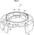
- FIG. 6is a perspective view illustrating an example of a configuration of a chassis 170. Note that FIG. 5(a) is a view of the stopper 160 seen from above, while FIG. 5(b) is a view of the stopper 160 seen from below.
- the security camera 100includes: an exterior cover 110; a lens unit 120; an inner cover 130; a pan leaf spring 140, which is an example of an elastic member; the pan base 150, which is an example of a supporting member; the stopper 160, which is an example of a rotation regulating member; the chassis 170, which is an example of a base; a main board 180; and a bottom plate 190.
- the exterior cover 110is a cover that covers the part of the security camera 100 excluding the bottom surface.
- the exterior cover 110is made of resin. Ribs are formed on the inner side of the exterior cover 110, and are in contact with the chassis 170. Accordingly, impact exerted on the exterior cover 110 is transferred to the chassis 170.
- the lens unit 120includes a lens, image sensors or the like, which generate electrical signals by forming an image from light that has passed through the lens and performing photoelectric conversion.
- the lens unit 120is supported by the pan base 150, and is rotatable in the tilt directions and the rotation direction.
- the lens unit 120includes therein a base plate, and is connected to wires such as lead wires extended from the outside. Note that a detailed configuration of the lens unit 120 will be described later.
- the inner cover 130is made of resin, for example, and covers the pan leaf spring 140. In addition, the inner cover 130 also has the function of protecting a sub board 182 fixed to the upper surface of the chassis 170. To the sub board 182, electronic components such as a switch are attached.
- the inner cover 130includes hooks 130b, which engage with the chassis 170. With the hooks 130b thus engaging with the chassis 170, the inner cover 130 is fixed to the chassis 170.
- the pan leaf spring 140is, for example, a circular, plate-shaped flat spring made of metal (such as SUS).
- the pan leaf spring 140presses the pan base 150 against the chassis 170.
- the pan leaf spring 140includes engagement holes 140b and protrusions 140c.
- the engagement holes 140bare formed in four respective bent parts 140a of the pan leaf spring 140.
- the engagement holes 140bengage with the chassis 170, and thereby the pan leaf spring 140 is fixed to the chassis 170.
- the protrusions 140cprotrude toward the pan base 150, and are in contact with the pan base 150.
- the four protrusions 140care formed at regular intervals in the circumferential direction.
- the protrusions 140cpress the pan base 150 (specifically, a base part 150a).
- the protrusions 140care formed by processing the pan leaf spring 140 by raising. Note that, although the protrusions 140c are formed at four portions in FIG. 3 , the protrusions 140c are not limited to this and may be formed at three portions or less.
- the pan base 150has the function of supporting the lens unit 120.
- the pan base 150supports the lens unit 120, and rotates in the pan direction, which is a predetermined rotating direction, with the lens unit 120.
- the pan base 150is rotatable in clockwise and counterclockwise pan directions (refer to FIG. 7 ).
- the pan base 150includes the base part 150a, a pair of supporting parts 150b, and a bent part 150c.
- the base part 150ahas a circular shape, and is rotatably mounted on the chassis 170.
- the base part 150ais pressed by the protrusions 140c of the pan leaf spring 140 positioned above. In this way, the position of the pan base 150 is maintained in the state where the pan base 150 is rotated.
- the pressure of the protrusions 140cis adjusted via the thickness of the pan leaf spring 140 and the protruding amount of the protrusions 140c.
- the supporting parts 150bare bent from the base part 150a toward the pan leaf spring 140, and support the lens unit 120.
- the lens unit 120is rotatable in the tilt directions with the supporting parts 150b serving as the rotation center.
- the bent part 150cis bent from the base part 150a toward the chassis 170, and is contactable to the stopper 160 attached to the chassis 170. When the bent part 150c comes into contact with the stopper 160, the rotation of the pan base 150 in any of the pan directions is regulated. In addition, a bending 150d for increasing the strength of the pan base 150 is formed at the periphery of the base part 150a.
- the stopper 160is made of resin, and is attached to the chassis 170.
- the stopper 160regulates rotation of the pan base 150 by coming in contact with the pan base 150 rotating in the pan direction while supporting the lens unit 120.
- the stopper 160comes into contact with the pan base 150 rotating in the clockwise or counterclockwise pan direction and thereby regulates the clockwise or counterclockwise rotation. In this way, the rotation amount of the lens unit 120 in the pan direction can be regulated.
- the stopper 160includes a convex contact part 160a contactable to the bent part 150c of the pan base 150. As illustrated in FIG. 5 , the convex contact part 160a is formed at a central portion of the stopper 160. The convex contact part 160a comes into contact with the bent part 150c, and thereby the rotation of the pan base 150 in the pan direction is regulated.
- the stopper 160is movably attached to a concave, move permitting part 170d of the chassis 170 so that the stopper 160 would be permitted to move a predetermined amount in the pan directions.
- the stopper 160includes a move part 160b ( FIG. 5 ), which moves along the concave, move permitting part 170d. Accordingly, along with rotation of the pan base 150 in any of the pan directions, the move part 160b can move at a predetermined angle in the pan direction while the convex contact part 160a is in contact with the pan base 150. With this configuration, the pan base 150 is permitted to rotate 360 degrees or more in the pan directions while the rotation is regulated by the stopper 160.
- the chassis 170is a base of the security camera 100, and is made by die-casting aluminum, for example. Since the chassis 170 is made by die-casting, it is possible to ensure the fastness property of the security camera 100.
- the pan base 150is mounted on the chassis 170 so as to be rotatable in the pan directions.
- the sub board 182(refer to FIG. 3 ) is attached to the chassis 170.
- the chassis 170includes engagement protrusions 170b, a mount surface 170c, and the concave, move permitting part 170d, which is an example of a move permitting part.
- the engagement protrusions 170bengage with the respective engagement holes 140b of the pan leaf spring 140.
- the engagement protrusions 170bare formed at respective positions corresponding to the four engagement holes 140b.
- the engagement protrusions 170bengage with the respective engagement holes 140b, and thereby the pan leaf spring 140 is fixed to the chassis 170.
- the base part 150a of the pan base 150is mounted on the mount face 170c.
- the base part 150arotates in any of the pan directions on the mount face 160c, and thereby the lens unit 120 supported by the pan base 150 rotates in the pan direction together.
- the concave, move permitting part 170dis a concave part formed in the inner peripheral surface of the chassis 170 to have a predetermined width in the pan directions.
- the stopper 160is attached.
- a guide groove 170e for guiding move of the move part 160b of the stopper 160is formed.
- the chassis 170is subjected to the impact exerted on the exterior cover 110. Since the chassis 170 in this embodiment is made by die-casting, the chassis 170 can withstand at the impact. In addition, since the chassis 170 is subjected to the impact, the exterior cover 110 need not be subjected directly to the impact, and hence is made of resin in this embodiment.
- the main board 180is provided with various kinds of electronic components such as circuits necessary for the operation of the security camera 100.
- the bottom plate 190is positioned under the main board 180, and the main board 180 is attached to the bottom plate 190. Moreover, the bottom plate 190 is fixed to the horizontal surface H such as a ceiling as that illustrated in FIG. 1 .
- FIG. 7provides views for explaining position adjustment of the pan base 150 in one of the pan directions. Note that the lens unit 120 supported by the pan base 150 is not illustrated in FIG. 7 for the purpose of illustration.
- the pan base 150is rotatable in the clockwise and counterclockwise pan directions presented in FIG. 7 . In the following, it is assumed that the pan base 150 is rotated counterclockwise from the state illustrated in FIG. 7(a) (first state) to the state illustrated in FIG. 7(b) .
- the userfurther rotates the pan base 150 counterclockwise, thereby reaching the state illustrated in FIG. 7(c) (third state), that is, a state where the stopper 160 further moves and comes into contact with a side wall of the concave, move permitting part 170d.
- the pan base 150is rotated 360 degrees or more.
- the stopper 160comes into contact with the pan base 150 to thereby regulate the counterclockwise rotation.
- the stopper 160since the stopper 160 being in contact with the pan base 150 moves counterclockwise in the concave, move permitting part 170d, the lens unit 120 supported by the pan base 150 can rotate in the counterclockwise pan direction 360 degrees or more.
- FIG. 8is a perspective view illustrating an example of an external configuration of the lens unit 120.
- FIG. 9is an exploded view of the lens unit 120.
- FIG. 10is a view illustrating the external configuration of the lens unit 120 in a state where a lower case 280 is removed.
- the lens unit 120includes an upper case 210, a lens holding part 220, a cylindrical member 230, a rotation base 240, a tilt base 250, a rotation leaf spring 260, press members 270, and the lower case 280.
- the upper case 210 together with the lower case 280forms an exterior cover of the lens unit 120.
- the upper case 210covers the lens holding part 220, while the lower case 280 covers the rotation base 240, the tilt base 250, and the rotation leaf spring 260.
- the upper case 210 and the lower case 280are made of resin, for example.
- the lens holding unit 220is made from steel metal or the like, and holds a lens 222.
- a board to which electronic components such as image sensors and the like are attachedis fixed.
- the lens holding part 220is fixed to the rotation base 240. Accordingly, when the rotation base 240 rotates in the rotation direction, the lens holding part 220 also rotates in the rotation direction.
- the cylindrical member 230is made of resin, for example, and is fitted to the rotation base 240, the tilt base 250, and the rotation leaf spring 260.
- the cylindrical member 230includes a ring-shaped wall 230a, multiple insertion holes 230b formed in the ring-shaped wall 230a, and a cut-out part 230c.
- the ring-shaped wall 230ais a wall protruding toward the lower case 280 and formed in a ring shape.
- the insertion holes 230bare formed at regular intervals in the ring-shaped wall 230a. In this embodiment, the four insertion holes 230b are formed.
- the press members 207are inserted into the four respective insertion holes 230b.
- the cut-out part 230cis formed by cutting a portion between two of the insertion holes 230b in the ring-shaped wall 230a. A protrusion of the rotation leaf spring 260 is locked in the cut-out part 230c, and thereby rotation of the rotation leaf spring 260 is prevented.
- the rotation base 240supports the lens holding part 220, and rotates in the optical axis direction (rotation direction) with the lens holding part 220.
- the rotation base 240includes protrusions contactable to the lower case 280. The protrusions come into contact with the lower case 280, and thereby the rotation of the rotation base 240 is regulated.
- the tilt base 250is supported so as to be rotatable in the tilt directions (vertical directions) with respect to the pan base 150 ( FIG. 3 ).
- the lens holding part 220also tilts.
- the rotation leaf spring 260is, for example, a circular, plate-shaped flat spring made of metal.
- the rotation leaf spring 260is positioned below the tilt base 250, and presses the tilt base 250 and the rotation base 240.
- the rotation leaf spring 260includes multiple protrusions 260a and a convex locking part 260b.
- the multiple protrusions 260afour protrusions are formed at regular intervals in the circumferential direction, and protrude toward the tilt base 250 and are thereby in contact with the tilt base 250.
- the protrusions 260aare formed by raising as the pan leaf spring 140.
- the convex locking part 260bis formed so as to protrude toward the center in the radius direction.
- the convex locking part 260bis locked in the cut-out part 230c of the cylindrical member 230, and thereby rotation of the rotation leaf spring 260 is prevented.
- the press members 270are inserted into the respective insertion holes 230b of the cylindrical member 230.
- the press members 270come into contact with the rotation leaf spring 260 when being inserted into the insertion holes 230. In this way, the press members 270 press the rotation base 240 and the tilt base 250 via the rotation leaf spring 260. With the pressing by the press members 270, the position of the rotated rotation base 240 is maintained.
- the stopper 160regulates rotation of the pan base 150 in the pan directions by coming into contact with the pan base 150 rotating with the lens unit 120, which enables regulation of the rotation amount of the lens unit 120 in the pan directions.
- the move permitting, convex part 170d of the chassis 170permits the stopper 160 being in contact with the pan base 150 to move a predetermined amount in the pan directions so that the pan base 150 can rotate 360 degrees or more in the rotation directions, which consequently allows the lens unit 360 to rotate 360 degrees or more in the pan directions.
- the configurationis not limited to this.
- a bent partmay be formed at the chassis 170
- a concave, move permitting partmay be formed at the pan base 150
- the stopper 160may be configured to move in the concave, move permitting part.
- the lens unit 360can rotate 360 degrees or more in the pan directions.
- stopper 160 and the concave, move permitting part 170d for permitting the lens unit 120 to rotate 360 degrees or more in the pan directionsdescription has been given of the stopper 160 and the concave, move permitting part 170d for permitting the lens unit 120 to rotate 360 degrees or more in the pan directions.
- the configurationis not limited to this.
- a stopper and a concave, move permitting part for permitting the lens unit 120 to rotate 360 degrees or more in the rotation directionmay be provided.
- the lens unit 120is rotated in the pan directions and the rotation direction manually by the user.
- the configurationis not limited to this.
- the security camera 100may automatically rotate the lens unit 120 in the pan directions and the rotation direction.
- the security camera 100as an example of an image capture device.
- the image capture deviceis not limited to this.
- the image capture devicemay be any device as long as being a camera that captures an image while rotating 360 degrees or more, at least in a predetermined rotating direction.
Landscapes
- Physics & Mathematics (AREA)
- General Physics & Mathematics (AREA)
- Engineering & Computer Science (AREA)
- Multimedia (AREA)
- Signal Processing (AREA)
- Optics & Photonics (AREA)
- Accessories Of Cameras (AREA)
- Studio Devices (AREA)
Description
- The present invention relates to an image capture device that captures an image of the surrounding environment while being rotated in a predetermined rotating direction.
- An example of an image capture device is a security camera that captures an image of the surrounding environment while the installation position is fixed. It is desirable for a security camera to have a lens being rotated in a predetermined rotating direction depending on the relationship between the area of which the lens of the security camera can capture an image and the place of which a user of the security camera desires to capture an image.
- Patent Literature 1 below discloses a security camera including a lens unit that includes a lens, and a supporting member that supports the lens unit and rotates in pan directions.
- Patent Literature 1:
JP 2012-93579A - In Patent Literature 1, however, the rotation amount of the lens unit in the pan directions is not regulated. This allows the lens unit to rotate in the pan directions without limitation, which may, for example, cause wires (such as lead wires) connected with the lens unit to be kinked. To avoid this, it is preferable to provide a rotation amount regulation mechanism for regulating the rotation amount of the lens unit.
- On the other hand, when, for example, a member for regulating the rotation of the supporting member by coming into contact with the supporting member is provided as a rotation amount regulation mechanism, it is difficult to rotate the lens unit 360 degrees in the pan directions. Such being the case, the function of the security camera as a means for crime prevention may not be exerted fully.
- In view of the above, the present disclosure proposes an image capture device capable of rotating a lens unit 360 degrees or more while regulating the rotation amount of the lens unit.
- Prior art includes
US5850579A andUS4890713A , disclosing an image capture device with a limited rotation angle. - According to the present disclosure, there is provided an image capture device including a lens unit that includes a lens, a supporting member that supports the lens unit and rotates in a predetermined rotating direction with the lens unit, a rotation regulating member that regulates rotation of the supporting member by coming into contact with the supporting member while the supporting member is rotating, and a move permitting part that permits the rotation regulating member being in contact with the supporting member to move a predetermined amount in the rotating direction in a manner that the supporting member is able to rotate 360 degrees or more in the rotating direction.
- According to the above image capture apparatus, since the rotation regulating member can regulate rotation of the supporting member by coming into contact with the supporting member, it becomes possible to regulate the rotation amount of the lens unit. Further, since the move permitting part permits the rotation regulating member being in contact with the supporting member to move a predetermined amount in the rotating direction in a manner that the supporting member is able to rotate 360 degrees or more in the rotating direction, the lens unit can rotate 360 degrees or more.
- As described above, according to the present disclosure, it is possible to rotate the lens unit 360 degrees or more while regulating the rotation amount of the lens unit.
- [
FIG. 1] FIG. 1 is a view illustrating an example of an external configuration of asecurity camera 100 according to an embodiment of the present disclosure. - [
FIG. 2] FIG. 2 is a view illustrating the external configuration of thesecurity camera 100 in a state where an exterior cover is removed. - [
FIG. 3] FIG. 3 is an exploded view of thesecurity camera 100. - [
FIG. 4] FIG. 4 is a perspective view illustrating an example of a configuration of apan base 150. - [
FIG. 5] FIG. 5 provides perspective views illustrating an example of a configuration of astopper 160. - [
FIG. 6] FIG. 6 is a perspective view illustrating an example of a configuration of achassis 170. - [
FIG. 7] FIG. 7 provides views for explaining position adjustment of thepan base 150 in pan directions. - [
FIG. 8] FIG. 8 is a perspective view illustrating an example of an external configuration of alens unit 120. - [
FIG. 9] FIG. 9 is an exploded view of thelens unit 120. - [
FIG. 10] FIG. 10 is a view illustrating the external configuration of thelens unit 120 in a state where a lower case is removed. - Hereinafter, a preferred embodiment of the present disclosure will be described in detail with reference to the appended drawings. Note that, in this specification and the drawings, elements that have substantially the same function and structure are denoted with the same reference signs, and repeated explanation is omitted.
- Note that the description will follow the following order.
- 1. Example of configuration of image capture device
- 2. Position adjustment of pan base in pan directions
- 3. Example of configuration of lens unit
- 4. Summary
- With reference to
FIG. 1 to FIG. 6 , description will be given of an example of a configuration of asecurity camera 100, which is an example of an image capture device according to an embodiment of the present disclosure. FIG. 1 is a view illustrating an example of an external configuration of thesecurity camera 100 according to the embodiment of the present disclosure. Thesecurity camera 100 is fixed to a horizontal surface H such as a ceiling of a room illustrated inFIG. 1 , for example. Thesecurity camera 100 includes a lens unit, and captures a video or a still image of the surrounding environment.- The lens unit can capture an image of the surrounding environment at various angles by moving in three types of directions (pan directions, tilt directions, and a rotation direction). Here, the pan directions correspond to directions parallel to the horizontal directions, the tilt directions correspond to directions along the vertical directions, and the rotation direction corresponds to a direction around the optical axis. In this embodiment, the lens unit is moved in the pan directions, the tilt directions, and the rotation direction manually by a user.
FIG. 2 is a view illustrating the external configuration of thesecurity camera 100 in a state where an exterior cover is moved.FIG. 3 is an exploded view of thesecurity camera 100.FIG. 4 is a perspective view illustrating an example of a configuration of apan base 150.FIG. 5 provides perspective views illustrating an example of a configuration of astopper 160.FIG. 6 is a perspective view illustrating an example of a configuration of achassis 170. Note thatFIG. 5(a) is a view of thestopper 160 seen from above, whileFIG. 5(b) is a view of thestopper 160 seen from below.- As illustrated in
FIG. 3 , thesecurity camera 100 includes: anexterior cover 110; alens unit 120; aninner cover 130; apan leaf spring 140, which is an example of an elastic member; thepan base 150, which is an example of a supporting member; thestopper 160, which is an example of a rotation regulating member; thechassis 170, which is an example of a base; amain board 180; and abottom plate 190. - (Exterior Cover 110)
- The
exterior cover 110 is a cover that covers the part of thesecurity camera 100 excluding the bottom surface. In this embodiment, theexterior cover 110 is made of resin. Ribs are formed on the inner side of theexterior cover 110, and are in contact with thechassis 170. Accordingly, impact exerted on theexterior cover 110 is transferred to thechassis 170. - The
lens unit 120 includes a lens, image sensors or the like, which generate electrical signals by forming an image from light that has passed through the lens and performing photoelectric conversion. Thelens unit 120 is supported by thepan base 150, and is rotatable in the tilt directions and the rotation direction. Thelens unit 120 includes therein a base plate, and is connected to wires such as lead wires extended from the outside. Note that a detailed configuration of thelens unit 120 will be described later. - The
inner cover 130 is made of resin, for example, and covers thepan leaf spring 140. In addition, theinner cover 130 also has the function of protecting asub board 182 fixed to the upper surface of thechassis 170. To thesub board 182, electronic components such as a switch are attached. Theinner cover 130 includeshooks 130b, which engage with thechassis 170. With thehooks 130b thus engaging with thechassis 170, theinner cover 130 is fixed to thechassis 170. - The
pan leaf spring 140 is, for example, a circular, plate-shaped flat spring made of metal (such as SUS). Thepan leaf spring 140 presses thepan base 150 against thechassis 170. Thepan leaf spring 140 includes engagement holes 140b andprotrusions 140c. - The engagement holes 140b are formed in four respective
bent parts 140a of thepan leaf spring 140. The engagement holes 140b engage with thechassis 170, and thereby thepan leaf spring 140 is fixed to thechassis 170. - The
protrusions 140c protrude toward thepan base 150, and are in contact with thepan base 150. For thepan leaf spring 140, the fourprotrusions 140c are formed at regular intervals in the circumferential direction. Theprotrusions 140c press the pan base 150 (specifically, abase part 150a). Theprotrusions 140c are formed by processing thepan leaf spring 140 by raising. Note that, although theprotrusions 140c are formed at four portions inFIG. 3 , theprotrusions 140c are not limited to this and may be formed at three portions or less. - The
pan base 150 has the function of supporting thelens unit 120. In addition, thepan base 150 supports thelens unit 120, and rotates in the pan direction, which is a predetermined rotating direction, with thelens unit 120. Thepan base 150 is rotatable in clockwise and counterclockwise pan directions (refer toFIG. 7 ). As illustrated inFIG. 4 , thepan base 150 includes thebase part 150a, a pair of supportingparts 150b, and abent part 150c. - The
base part 150a has a circular shape, and is rotatably mounted on thechassis 170. Thebase part 150a is pressed by theprotrusions 140c of thepan leaf spring 140 positioned above. In this way, the position of thepan base 150 is maintained in the state where thepan base 150 is rotated. The pressure of theprotrusions 140c is adjusted via the thickness of thepan leaf spring 140 and the protruding amount of theprotrusions 140c. - The supporting
parts 150b are bent from thebase part 150a toward thepan leaf spring 140, and support thelens unit 120. Thelens unit 120 is rotatable in the tilt directions with the supportingparts 150b serving as the rotation center. - The
bent part 150c is bent from thebase part 150a toward thechassis 170, and is contactable to thestopper 160 attached to thechassis 170. When thebent part 150c comes into contact with thestopper 160, the rotation of thepan base 150 in any of the pan directions is regulated. In addition, a bending 150d for increasing the strength of thepan base 150 is formed at the periphery of thebase part 150a. - The
stopper 160 is made of resin, and is attached to thechassis 170. Thestopper 160 regulates rotation of thepan base 150 by coming in contact with thepan base 150 rotating in the pan direction while supporting thelens unit 120. In this embodiment, thestopper 160 comes into contact with thepan base 150 rotating in the clockwise or counterclockwise pan direction and thereby regulates the clockwise or counterclockwise rotation. In this way, the rotation amount of thelens unit 120 in the pan direction can be regulated. - The
stopper 160 includes aconvex contact part 160a contactable to thebent part 150c of thepan base 150. As illustrated inFIG. 5 , theconvex contact part 160a is formed at a central portion of thestopper 160. Theconvex contact part 160a comes into contact with thebent part 150c, and thereby the rotation of thepan base 150 in the pan direction is regulated. - Moreover, the
stopper 160 is movably attached to a concave,move permitting part 170d of thechassis 170 so that thestopper 160 would be permitted to move a predetermined amount in the pan directions. Thestopper 160 includes amove part 160b (FIG. 5 ), which moves along the concave,move permitting part 170d. Accordingly, along with rotation of thepan base 150 in any of the pan directions, themove part 160b can move at a predetermined angle in the pan direction while theconvex contact part 160a is in contact with thepan base 150. With this configuration, thepan base 150 is permitted to rotate 360 degrees or more in the pan directions while the rotation is regulated by thestopper 160. - The
chassis 170 is a base of thesecurity camera 100, and is made by die-casting aluminum, for example. Since thechassis 170 is made by die-casting, it is possible to ensure the fastness property of thesecurity camera 100. Thepan base 150 is mounted on thechassis 170 so as to be rotatable in the pan directions. In addition, the sub board 182 (refer toFIG. 3 ) is attached to thechassis 170. As illustrated inFIG. 6 , thechassis 170 includesengagement protrusions 170b, amount surface 170c, and the concave,move permitting part 170d, which is an example of a move permitting part. - The
engagement protrusions 170b engage with therespective engagement holes 140b of thepan leaf spring 140. Theengagement protrusions 170b are formed at respective positions corresponding to the fourengagement holes 140b. Theengagement protrusions 170b engage with therespective engagement holes 140b, and thereby thepan leaf spring 140 is fixed to thechassis 170. - On the
mount face 170c, thebase part 150a of thepan base 150 is mounted. Thebase part 150a rotates in any of the pan directions on the mount face 160c, and thereby thelens unit 120 supported by thepan base 150 rotates in the pan direction together. - The concave,
move permitting part 170d is a concave part formed in the inner peripheral surface of thechassis 170 to have a predetermined width in the pan directions. In the concave,move permitting part 170d, thestopper 160 is attached. In the concave,move permitting part 170d, aguide groove 170e for guiding move of themove part 160b of thestopper 160 is formed. With this configuration, the concave,move permitting part 170d permits thestopper 160 being in contact with thepan base 150 to move a predetermined amount in the rotating direction (clockwise or counterclockwise), to thereby permit thepan base 150 to be rotatable 360 degrees or more in the pan direction. - Meanwhile, as described above, the ribs formed on the inner side of the
exterior cover 110 are in contact with thechassis 170. For this reason, thechassis 170 is subjected to the impact exerted on theexterior cover 110. Since thechassis 170 in this embodiment is made by die-casting, thechassis 170 can withstand at the impact. In addition, since thechassis 170 is subjected to the impact, theexterior cover 110 need not be subjected directly to the impact, and hence is made of resin in this embodiment. - The
main board 180 is provided with various kinds of electronic components such as circuits necessary for the operation of thesecurity camera 100. Thebottom plate 190 is positioned under themain board 180, and themain board 180 is attached to thebottom plate 190. Moreover, thebottom plate 190 is fixed to the horizontal surface H such as a ceiling as that illustrated inFIG. 1 . - With reference to
FIG. 7 , description will be given of position adjustment of thepan base 150, holding the lens unit 12, in the pan directions. The position adjustment of thepan base 150 in the pan directions is performed in this embodiment in such a way that a user rotates thepan base 150 manually. FIG. 7 provides views for explaining position adjustment of thepan base 150 in one of the pan directions. Note that thelens unit 120 supported by thepan base 150 is not illustrated inFIG. 7 for the purpose of illustration.- The
pan base 150 is rotatable in the clockwise and counterclockwise pan directions presented inFIG. 7 . In the following, it is assumed that thepan base 150 is rotated counterclockwise from the state illustrated inFIG. 7(a) (first state) to the state illustrated inFIG. 7(b) . - When the
pan base 150 is further rotated counterclockwise from the state illustrated inFIG. 7(b) (second state), thebent part 150c of thepan base 150 comes into contact with theconvex contact part 160a of thestopper 160 attached to the concave,move permitting part 170d. Then, when the user further rotates thepan base 150 counterclockwise, pressure is applied to thestopper 160 by thebent part 150c, and thereby themove part 160b of thestopper 160 moves counterclockwise along theguide groove 170e of the concave,move permitting part 170d. - Then, the user further rotates the
pan base 150 counterclockwise, thereby reaching the state illustrated inFIG. 7(c) (third state), that is, a state where thestopper 160 further moves and comes into contact with a side wall of the concave,move permitting part 170d. As is illustrated inFIG. 7(a) and FIG. 7(c) , thepan base 150 is rotated 360 degrees or more. - In other words, when the user rotates the
pan base 150 counterclockwise in the pan direction, thestopper 160 comes into contact with thepan base 150 to thereby regulate the counterclockwise rotation. At the same time, since thestopper 160 being in contact with thepan base 150 moves counterclockwise in the concave,move permitting part 170d, thelens unit 120 supported by thepan base 150 can rotate in the counterclockwise pan direction 360 degrees or more. - Although description has been given above of the example in which the
pan base 150 rotates in the counterclockwise pan direction, the same applies to the case where thepan base 150 rotates clockwise. Specifically, as in the above, in the case of moving from the state illustrated inFIG. 7(c) to the state illustrated inFIG. 7(a) , since thestopper 160 moves clockwise in the concave,move permitting part 170d while regulating the clockwise rotation by coming into contact with thepan base 150, thelens unit 120 supported by thepan base 150 can rotate in the clockwise pan direction 360 degrees or more. - With reference to
FIG. 8 to FIG. 10 , description will be given of an example of a configuration of thelens unit 120. FIG. 8 is a perspective view illustrating an example of an external configuration of thelens unit 120.FIG. 9 is an exploded view of thelens unit 120.FIG. 10 is a view illustrating the external configuration of thelens unit 120 in a state where alower case 280 is removed.- As illustrated in
FIG. 9 , thelens unit 120 includes anupper case 210, alens holding part 220, acylindrical member 230, arotation base 240, atilt base 250, arotation leaf spring 260,press members 270, and thelower case 280. - The
upper case 210 together with thelower case 280 forms an exterior cover of thelens unit 120. Theupper case 210 covers thelens holding part 220, while thelower case 280 covers therotation base 240, thetilt base 250, and therotation leaf spring 260. Theupper case 210 and thelower case 280 are made of resin, for example. - The
lens holding unit 220 is made from steel metal or the like, and holds alens 222. In thelens holding part 220, a board to which electronic components such as image sensors and the like are attached is fixed. Thelens holding part 220 is fixed to therotation base 240. Accordingly, when therotation base 240 rotates in the rotation direction, thelens holding part 220 also rotates in the rotation direction. - The
cylindrical member 230 is made of resin, for example, and is fitted to therotation base 240, thetilt base 250, and therotation leaf spring 260. Thecylindrical member 230 includes a ring-shapedwall 230a,multiple insertion holes 230b formed in the ring-shapedwall 230a, and a cut-outpart 230c. - The ring-shaped
wall 230a is a wall protruding toward thelower case 280 and formed in a ring shape. The insertion holes 230b are formed at regular intervals in the ring-shapedwall 230a. In this embodiment, the fourinsertion holes 230b are formed. The press members 207 are inserted into the fourrespective insertion holes 230b. The cut-outpart 230c is formed by cutting a portion between two of the insertion holes 230b in the ring-shapedwall 230a. A protrusion of therotation leaf spring 260 is locked in the cut-outpart 230c, and thereby rotation of therotation leaf spring 260 is prevented. - The
rotation base 240 supports thelens holding part 220, and rotates in the optical axis direction (rotation direction) with thelens holding part 220. Therotation base 240 includes protrusions contactable to thelower case 280. The protrusions come into contact with thelower case 280, and thereby the rotation of therotation base 240 is regulated. - The
tilt base 250 is supported so as to be rotatable in the tilt directions (vertical directions) with respect to the pan base 150 (FIG. 3 ). When thetilt base 250 tilts, thelens holding part 220 also tilts. - The
rotation leaf spring 260 is, for example, a circular, plate-shaped flat spring made of metal. Therotation leaf spring 260 is positioned below thetilt base 250, and presses thetilt base 250 and therotation base 240. Therotation leaf spring 260 includesmultiple protrusions 260a and aconvex locking part 260b. - As the
multiple protrusions 260a, four protrusions are formed at regular intervals in the circumferential direction, and protrude toward thetilt base 250 and are thereby in contact with thetilt base 250. Theprotrusions 260a are formed by raising as thepan leaf spring 140. Theconvex locking part 260b is formed so as to protrude toward the center in the radius direction. Theconvex locking part 260b is locked in the cut-outpart 230c of thecylindrical member 230, and thereby rotation of therotation leaf spring 260 is prevented. - The
press members 270 are inserted into therespective insertion holes 230b of thecylindrical member 230. Thepress members 270 come into contact with therotation leaf spring 260 when being inserted into the insertion holes 230. In this way, thepress members 270 press therotation base 240 and thetilt base 250 via therotation leaf spring 260. With the pressing by thepress members 270, the position of the rotatedrotation base 240 is maintained. - In the above-described
security camera 100, thestopper 160 regulates rotation of thepan base 150 in the pan directions by coming into contact with thepan base 150 rotating with thelens unit 120, which enables regulation of the rotation amount of thelens unit 120 in the pan directions. At the same time, the move permitting,convex part 170d of thechassis 170 permits thestopper 160 being in contact with thepan base 150 to move a predetermined amount in the pan directions so that thepan base 150 can rotate 360 degrees or more in the rotation directions, which consequently allows the lens unit 360 to rotate 360 degrees or more in the pan directions. With this, since the lens unit 360 can capture an image all around in the pan directions even when thestopper 160 is provided, a decrease in the function of thesecurity camera 100 can be prevented. - Note that, although the
bent part 150c is formed at thepan base 150, the concave,move permitting part 170d is formed at thechassis 170, and thestopper 160 is configured to move in the concave,move permitting part 170d, in this embodiment, the configuration is not limited to this. For example, a bent part may be formed at thechassis 170, a concave, move permitting part may be formed at thepan base 150, and thestopper 160 may be configured to move in the concave, move permitting part. In this case, as in the above, the lens unit 360 can rotate 360 degrees or more in the pan directions. - Moreover, in the above-described embodiment, description has been given by taking the
stopper 160 as an example of a rotation regulating member and the concave,move permitting part 170d as an example of a move permitting part. However, the configuration is not limited to this, and any other configuration may be used as long as being capable of regulating the rotation of thepan base 150 while permitting move of the rotation regulating member. - Moreover, in the above-described embodiment, description has been given of the
stopper 160 and the concave,move permitting part 170d for permitting thelens unit 120 to rotate 360 degrees or more in the pan directions. However, the configuration is not limited to this. For example, a stopper and a concave, move permitting part for permitting thelens unit 120 to rotate 360 degrees or more in the rotation direction may be provided. - Moreover, in the above-described embodiment, the
lens unit 120 is rotated in the pan directions and the rotation direction manually by the user. However, the configuration is not limited to this. For example, thesecurity camera 100 may automatically rotate thelens unit 120 in the pan directions and the rotation direction. - Moreover, in the above-described embodiment, description has been given by taking the
security camera 100 as an example of an image capture device. However, the image capture device is not limited to this. The image capture device may be any device as long as being a camera that captures an image while rotating 360 degrees or more, at least in a predetermined rotating direction. - The preferred embodiment of the present disclosure has been described above in detail with reference to the accompanying drawings, whilst the technical scope of the present disclosure is not limited to the above examples, of course. A person skilled in the art of the present disclosure may find various alterations and modifications within the technical ideas described in the scope of the claims, and it should be understood that they will naturally come under the technical scope of the present disclosure.
- Additionally, the present technology may also be configured as defined in the claims.
- 100
- security camera
- 120
- lens unit
- 122
- lens
- 140
- pan leaf spring
- 140c
- protrusion
- 150
- pan base
- 150a
- base part
- 150b
- supporting part
- 150c
- bent part
- 160
- stopper
- 160a
- convex contact part
- 160b
- move part
- 170
- chassis
- 170d
- concave, move permitting part
- 170e
- guide groove
- 220
- lens holding part
- 230
- cylindrical member
- 240
- rotation base
- 250
- tilt base
- 260
- rotation leaf spring
- 270
- press member
Claims (7)
- An image capture device (100) comprising:a lens unit (120) that includes a lens (122);a supporting member (150) configured to support the lens unit and to rotate in a predetermined rotating direction with the lens unit;a rotation regulating member (160) configured to regulate rotation of the supporting member by coming into contact with the supporting member while the supporting member is rotating; anda move permitting part (170d) configured to permit the rotation regulating member being in contact with the supporting member to move a predetermined amount in the rotating direction in a manner that the supporting member is rotatable 360 degrees or more in the rotating direction;characterized in that a rotation axis of the rotation regulating member and a rotation axis of the supporting member are the same, andin that a rotation direction of the rotation regulating member is the same as a rotation direction of the supporting member while the rotation regulating member is moving and is in contact with the supporting member.
- The image capture device according to claim 1, further comprising:a base (170) on which the supporting member is mounted rotatably,
wherein the move permitting part is a concave part formed in the base in the rotating direction. - The image capture device according to claim 2, wherein the rotation regulating member is rotatably attached to the concave part.
- The image capture device (100) according to claim 1,
wherein the supporting member (150) includesa circular base part (150a), anda bent part (150c) that is bent from the base part, andwherein the rotation regulating member (160) is configured to regulate the rotation of the supporting member by coming into contact with the bent part. - The image capture device (100) according to claim 1,
wherein the supporting member (150) is rotatable clockwise and counterclockwise in the rotating direction,
wherein the rotation regulating member (160) is configured to regulate the rotation of the supporting member by coming into contact with the supporting member while the supporting member is rotating clockwise or counterclockwise, and
wherein the move permitting part (170d) is configured to permit the rotation regulating member being in contact with the supporting member to move the predetermined amount clockwise or counterclockwise. - The image capture device according to claim 1, wherein the predetermined rotating direction is a pan direction.
- The image capture device (100) according to claim 1,
wherein the supporting member (150) includesa circular base part (150a), anda supporting part (150b) that is bent from the base part and supports the lens unit,the image capture device further comprising:a plate-shaped elastic member (140) including a plurality of protrusions (140c) configured to press the base part.
Applications Claiming Priority (2)
| Application Number | Priority Date | Filing Date | Title |
|---|---|---|---|
| JP2012195201AJP6064458B2 (en) | 2012-09-05 | 2012-09-05 | Imaging device |
| PCT/JP2013/071050WO2014038328A1 (en) | 2012-09-05 | 2013-08-02 | Image pickup apparatus |
Publications (3)
| Publication Number | Publication Date |
|---|---|
| EP2894844A1 EP2894844A1 (en) | 2015-07-15 |
| EP2894844A4 EP2894844A4 (en) | 2016-04-13 |
| EP2894844B1true EP2894844B1 (en) | 2018-03-07 |
Family
ID=50236945
Family Applications (1)
| Application Number | Title | Priority Date | Filing Date |
|---|---|---|---|
| EP13836100.1AActiveEP2894844B1 (en) | 2012-09-05 | 2013-08-02 | Image pickup apparatus |
Country Status (5)
| Country | Link |
|---|---|
| US (2) | US9565345B2 (en) |
| EP (1) | EP2894844B1 (en) |
| JP (1) | JP6064458B2 (en) |
| CN (1) | CN104604211B (en) |
| WO (1) | WO2014038328A1 (en) |
Families Citing this family (31)
| Publication number | Priority date | Publication date | Assignee | Title |
|---|---|---|---|---|
| JP6064458B2 (en) | 2012-09-05 | 2017-01-25 | ソニー株式会社 | Imaging device |
| USD820895S1 (en) | 2014-07-16 | 2018-06-19 | Axis Ab | Monitoring camera |
| DE202014103541U1 (en)* | 2014-07-30 | 2015-11-02 | Burg-Wächter Kg | camera assembly |
| USD849091S1 (en)* | 2015-04-22 | 2019-05-21 | Mobotix Ag | Housing for a surveillance camera |
| USD811462S1 (en) | 2015-11-16 | 2018-02-27 | Axis Ab | Monitoring camera |
| JP1584677S (en)* | 2016-02-02 | 2017-08-28 | ||
| EP3290274B1 (en)* | 2016-09-01 | 2019-04-03 | Veoneer Sweden AB | Imaging system for a motor vehicle |
| US20180299750A1 (en)* | 2017-04-14 | 2018-10-18 | Parrot Drones | Camera support system |
| JP1595866S (en)* | 2017-07-24 | 2018-01-29 | ||
| EP3447574B1 (en)* | 2017-08-21 | 2019-07-31 | Axis AB | Camera and method for controlled dew formation inside a camera |
| USD876507S1 (en)* | 2017-09-30 | 2020-02-25 | Hangzhou Hikvision Digital Technology Co., Ltd. | Cover for a camera |
| USD881975S1 (en) | 2017-09-30 | 2020-04-21 | Hangzhou Hikvision Digital Technology Co., Ltd | Camera |
| CN207830867U (en)* | 2017-12-12 | 2018-09-07 | 杭州海康威视数字技术股份有限公司 | A kind of video camera |
| USD882663S1 (en)* | 2018-01-15 | 2020-04-28 | Axis Ab | Camera |
| USD866634S1 (en) | 2018-01-26 | 2019-11-12 | Cisco Technology, Inc. | Camera housing |
| USD874533S1 (en) | 2018-02-06 | 2020-02-04 | Cisco Technology, Inc. | Camera housing |
| USD875808S1 (en) | 2018-02-06 | 2020-02-18 | Cisco Technology, Inc. | Camera housing |
| KR102525183B1 (en)* | 2018-04-24 | 2023-04-25 | 한화비전 주식회사 | Security camera |
| USD870181S1 (en)* | 2018-06-11 | 2019-12-17 | Honeywell International Inc. | Surveillance camera |
| TWD195632S (en)* | 2018-09-17 | 2019-01-21 | 晶睿通訊股份有限公司 | Surveillance camera |
| TWD195633S (en)* | 2018-09-17 | 2019-01-21 | 晶睿通訊股份有限公司 | Surveillance camera |
| US11070712B2 (en)* | 2019-08-30 | 2021-07-20 | Puwell Technology Llc | Method and system for control of a digital camera system |
| JP1667896S (en)* | 2020-02-10 | 2020-09-14 | ||
| USD959532S1 (en)* | 2020-04-01 | 2022-08-02 | Axis Ab | Monitoring camera |
| CA201293S (en)* | 2020-08-18 | 2022-06-27 | Axis Ab | Monitoring camera |
| CA201294S (en)* | 2020-08-18 | 2022-06-27 | Axis Ab | Monitoring camera |
| USD991056S1 (en)* | 2020-09-28 | 2023-07-04 | Unity Technologies Sf | Performance capture marker housing |
| CN112327566B (en)* | 2020-11-11 | 2022-08-26 | 杭州海康威视数字技术股份有限公司 | Photographing apparatus |
| USD989153S1 (en)* | 2021-02-17 | 2023-06-13 | Axis Ab | Monitoring camera |
| JP7566664B2 (en)* | 2021-02-25 | 2024-10-15 | キヤノン株式会社 | Imaging device |
| USD992626S1 (en)* | 2021-03-30 | 2023-07-18 | Axis Ab | Monitoring camera |
Family Cites Families (20)
| Publication number | Priority date | Publication date | Assignee | Title |
|---|---|---|---|---|
| US4890713A (en) | 1988-07-22 | 1990-01-02 | Pagano Raymond V | Pan and tilt motor for surveillance camera |
| JPH0970778A (en)* | 1995-09-08 | 1997-03-18 | Yamaha Motor Co Ltd | Pendulum type robot |
| US5850579A (en)* | 1997-06-09 | 1998-12-15 | Addco, Inc. | Pan/tilt support with concentric drive shafts |
| US6715940B2 (en)* | 2002-09-10 | 2004-04-06 | General Electric Company | Rugged miniature pan/tilt dome camera assembly |
| JP4515106B2 (en)* | 2004-02-04 | 2010-07-28 | パナソニック株式会社 | Dome camera |
| US20060023113A1 (en)* | 2004-07-28 | 2006-02-02 | Acutvista Innovation Co., Ltd. | Ball type camera able of changing lens module |
| US7217045B2 (en)* | 2005-01-03 | 2007-05-15 | Robert Bosch Gmbh | Connect/disconnect mechanism for a surveillance camera head |
| KR100718088B1 (en)* | 2005-08-19 | 2007-05-16 | 삼성전자주식회사 | Surveillance camera |
| JP4566126B2 (en)* | 2005-12-28 | 2010-10-20 | 三洋電機株式会社 | Locking mechanism for rotating body and electric device support using the locking mechanism |
| JP4404120B2 (en)* | 2007-09-04 | 2010-01-27 | ソニー株式会社 | Lens barrel rotation detection device and lens barrel rotation imaging device |
| US8405766B2 (en)* | 2008-07-24 | 2013-03-26 | Panasonic Corporation | Camera device and method for adjusting the orientation of the window of a camera cover |
| JP5165762B2 (en)* | 2008-09-09 | 2013-03-21 | パナソニック株式会社 | Dome camera |
| JP2010074477A (en)* | 2008-09-18 | 2010-04-02 | Sony Corp | Electronic device |
| CN101873423B (en)* | 2009-04-27 | 2012-02-15 | 上海乐金广电电子有限公司 | Automatic turn-over control device and method of surveillance camera |
| JP5451298B2 (en)* | 2009-10-14 | 2014-03-26 | キヤノン株式会社 | Lens device |
| JP2012032636A (en)* | 2010-07-30 | 2012-02-16 | Nidec Copal Corp | Pan and tilt device |
| JP5672957B2 (en) | 2010-10-27 | 2015-02-18 | ソニー株式会社 | Imaging device and leaf spring |
| JP5651268B2 (en)* | 2012-02-14 | 2015-01-07 | 富士フイルム株式会社 | Dome camera |
| JP6064458B2 (en)* | 2012-09-05 | 2017-01-25 | ソニー株式会社 | Imaging device |
| JP6283909B2 (en)* | 2013-03-01 | 2018-02-28 | パナソニックIpマネジメント株式会社 | Camera device and method of controlling camera device |
- 2012
- 2012-09-05JPJP2012195201Apatent/JP6064458B2/enactiveActive
- 2013
- 2013-08-02EPEP13836100.1Apatent/EP2894844B1/enactiveActive
- 2013-08-02WOPCT/JP2013/071050patent/WO2014038328A1/enactiveApplication Filing
- 2013-08-02USUS14/424,216patent/US9565345B2/enactiveActive
- 2013-08-02CNCN201380044622.8Apatent/CN104604211B/enactiveActive
- 2016
- 2016-12-22USUS15/389,040patent/US9860435B2/enactiveActive
Non-Patent Citations (1)
| Title |
|---|
| None* |
Also Published As
| Publication number | Publication date |
|---|---|
| US9860435B2 (en) | 2018-01-02 |
| EP2894844A1 (en) | 2015-07-15 |
| US9565345B2 (en) | 2017-02-07 |
| CN104604211B (en) | 2018-04-06 |
| JP6064458B2 (en) | 2017-01-25 |
| JP2014053678A (en) | 2014-03-20 |
| US20170104908A1 (en) | 2017-04-13 |
| CN104604211A (en) | 2015-05-06 |
| WO2014038328A1 (en) | 2014-03-13 |
| EP2894844A4 (en) | 2016-04-13 |
| US20150326759A1 (en) | 2015-11-12 |
Similar Documents
| Publication | Publication Date | Title |
|---|---|---|
| EP2894844B1 (en) | Image pickup apparatus | |
| US9497362B2 (en) | Imaging device and plate spring | |
| EP3557859B1 (en) | Multi-lens camera | |
| US8506181B2 (en) | Imaging device and plate spring | |
| CA3094560C (en) | Multi-view camera and lens adjustment device | |
| US8405766B2 (en) | Camera device and method for adjusting the orientation of the window of a camera cover | |
| US8783974B2 (en) | Photographic apparatus and case structure thereof | |
| US20210266429A1 (en) | Imaging apparatus | |
| JP6330898B2 (en) | Imaging device | |
| JP6597832B2 (en) | Imaging device | |
| KR100492121B1 (en) | Dome shaped closed circuit television camera assembly | |
| KR200468076Y1 (en) | Dome camera for cctv | |
| JP2008046493A (en) | Imaging apparatus | |
| US11843864B2 (en) | Image capturing apparatus | |
| JP2014235182A (en) | Image-capturing device | |
| JP3894451B2 (en) | Surveillance camera device | |
| CN212723627U (en) | Camera device and photographing system including the same | |
| CN219890576U (en) | Support adjusting device | |
| CN102547085B (en) | Imaging device and leaf spring | |
| JP2013232708A (en) | Dome camera | |
| KR20230123831A (en) | Dome type camera for easily adjusting view field direction |
Legal Events
| Date | Code | Title | Description |
|---|---|---|---|
| PUAI | Public reference made under article 153(3) epc to a published international application that has entered the european phase | Free format text:ORIGINAL CODE: 0009012 | |
| 17P | Request for examination filed | Effective date:20150223 | |
| AK | Designated contracting states | Kind code of ref document:A1 Designated state(s):AL AT BE BG CH CY CZ DE DK EE ES FI FR GB GR HR HU IE IS IT LI LT LU LV MC MK MT NL NO PL PT RO RS SE SI SK SM TR | |
| AX | Request for extension of the european patent | Extension state:BA ME | |
| DAX | Request for extension of the european patent (deleted) | ||
| RA4 | Supplementary search report drawn up and despatched (corrected) | Effective date:20160314 | |
| RIC1 | Information provided on ipc code assigned before grant | Ipc:G03B 17/00 20060101ALI20160308BHEP Ipc:H04N 5/225 20060101AFI20160308BHEP Ipc:G03B 17/02 20060101ALI20160308BHEP Ipc:G03B 17/56 20060101ALI20160308BHEP Ipc:G03B 15/00 20060101ALI20160308BHEP Ipc:G03B 17/12 20060101ALI20160308BHEP | |
| RIC1 | Information provided on ipc code assigned before grant | Ipc:G03B 17/56 20060101ALI20170810BHEP Ipc:H04N 5/225 20060101AFI20170810BHEP Ipc:G03B 17/00 20060101ALI20170810BHEP Ipc:G03B 17/12 20060101ALI20170810BHEP Ipc:G03B 17/02 20060101ALI20170810BHEP Ipc:G02B 7/02 20060101ALI20170810BHEP Ipc:G03B 15/00 20060101ALI20170810BHEP | |
| GRAP | Despatch of communication of intention to grant a patent | Free format text:ORIGINAL CODE: EPIDOSNIGR1 | |
| STAA | Information on the status of an ep patent application or granted ep patent | Free format text:STATUS: GRANT OF PATENT IS INTENDED | |
| INTG | Intention to grant announced | Effective date:20170928 | |
| GRAS | Grant fee paid | Free format text:ORIGINAL CODE: EPIDOSNIGR3 | |
| GRAA | (expected) grant | Free format text:ORIGINAL CODE: 0009210 | |
| STAA | Information on the status of an ep patent application or granted ep patent | Free format text:STATUS: THE PATENT HAS BEEN GRANTED | |
| AK | Designated contracting states | Kind code of ref document:B1 Designated state(s):AL AT BE BG CH CY CZ DE DK EE ES FI FR GB GR HR HU IE IS IT LI LT LU LV MC MK MT NL NO PL PT RO RS SE SI SK SM TR | |
| REG | Reference to a national code | Ref country code:GB Ref legal event code:FG4D | |
| REG | Reference to a national code | Ref country code:CH Ref legal event code:EP Ref country code:AT Ref legal event code:REF Ref document number:977768 Country of ref document:AT Kind code of ref document:T Effective date:20180315 | |
| REG | Reference to a national code | Ref country code:DE Ref legal event code:R096 Ref document number:602013034203 Country of ref document:DE | |
| REG | Reference to a national code | Ref country code:IE Ref legal event code:FG4D | |
| REG | Reference to a national code | Ref country code:NL Ref legal event code:FP | |
| REG | Reference to a national code | Ref country code:LT Ref legal event code:MG4D | |
| PG25 | Lapsed in a contracting state [announced via postgrant information from national office to epo] | Ref country code:FI Free format text:LAPSE BECAUSE OF FAILURE TO SUBMIT A TRANSLATION OF THE DESCRIPTION OR TO PAY THE FEE WITHIN THE PRESCRIBED TIME-LIMIT Effective date:20180307 Ref country code:CY Free format text:LAPSE BECAUSE OF FAILURE TO SUBMIT A TRANSLATION OF THE DESCRIPTION OR TO PAY THE FEE WITHIN THE PRESCRIBED TIME-LIMIT Effective date:20180307 Ref country code:LT Free format text:LAPSE BECAUSE OF FAILURE TO SUBMIT A TRANSLATION OF THE DESCRIPTION OR TO PAY THE FEE WITHIN THE PRESCRIBED TIME-LIMIT Effective date:20180307 Ref country code:NO Free format text:LAPSE BECAUSE OF FAILURE TO SUBMIT A TRANSLATION OF THE DESCRIPTION OR TO PAY THE FEE WITHIN THE PRESCRIBED TIME-LIMIT Effective date:20180607 Ref country code:ES Free format text:LAPSE BECAUSE OF FAILURE TO SUBMIT A TRANSLATION OF THE DESCRIPTION OR TO PAY THE FEE WITHIN THE PRESCRIBED TIME-LIMIT Effective date:20180307 Ref country code:HR Free format text:LAPSE BECAUSE OF FAILURE TO SUBMIT A TRANSLATION OF THE DESCRIPTION OR TO PAY THE FEE WITHIN THE PRESCRIBED TIME-LIMIT Effective date:20180307 | |
| REG | Reference to a national code | Ref country code:AT Ref legal event code:MK05 Ref document number:977768 Country of ref document:AT Kind code of ref document:T Effective date:20180307 | |
| PG25 | Lapsed in a contracting state [announced via postgrant information from national office to epo] | Ref country code:BG Free format text:LAPSE BECAUSE OF FAILURE TO SUBMIT A TRANSLATION OF THE DESCRIPTION OR TO PAY THE FEE WITHIN THE PRESCRIBED TIME-LIMIT Effective date:20180607 Ref country code:LV Free format text:LAPSE BECAUSE OF FAILURE TO SUBMIT A TRANSLATION OF THE DESCRIPTION OR TO PAY THE FEE WITHIN THE PRESCRIBED TIME-LIMIT Effective date:20180307 Ref country code:SE Free format text:LAPSE BECAUSE OF FAILURE TO SUBMIT A TRANSLATION OF THE DESCRIPTION OR TO PAY THE FEE WITHIN THE PRESCRIBED TIME-LIMIT Effective date:20180307 Ref country code:RS Free format text:LAPSE BECAUSE OF FAILURE TO SUBMIT A TRANSLATION OF THE DESCRIPTION OR TO PAY THE FEE WITHIN THE PRESCRIBED TIME-LIMIT Effective date:20180307 Ref country code:GR Free format text:LAPSE BECAUSE OF FAILURE TO SUBMIT A TRANSLATION OF THE DESCRIPTION OR TO PAY THE FEE WITHIN THE PRESCRIBED TIME-LIMIT Effective date:20180608 | |
| PG25 | Lapsed in a contracting state [announced via postgrant information from national office to epo] | Ref country code:PL Free format text:LAPSE BECAUSE OF FAILURE TO SUBMIT A TRANSLATION OF THE DESCRIPTION OR TO PAY THE FEE WITHIN THE PRESCRIBED TIME-LIMIT Effective date:20180307 Ref country code:EE Free format text:LAPSE BECAUSE OF FAILURE TO SUBMIT A TRANSLATION OF THE DESCRIPTION OR TO PAY THE FEE WITHIN THE PRESCRIBED TIME-LIMIT Effective date:20180307 Ref country code:RO Free format text:LAPSE BECAUSE OF FAILURE TO SUBMIT A TRANSLATION OF THE DESCRIPTION OR TO PAY THE FEE WITHIN THE PRESCRIBED TIME-LIMIT Effective date:20180307 Ref country code:AL Free format text:LAPSE BECAUSE OF FAILURE TO SUBMIT A TRANSLATION OF THE DESCRIPTION OR TO PAY THE FEE WITHIN THE PRESCRIBED TIME-LIMIT Effective date:20180307 Ref country code:IT Free format text:LAPSE BECAUSE OF FAILURE TO SUBMIT A TRANSLATION OF THE DESCRIPTION OR TO PAY THE FEE WITHIN THE PRESCRIBED TIME-LIMIT Effective date:20180307 | |
| PG25 | Lapsed in a contracting state [announced via postgrant information from national office to epo] | Ref country code:AT Free format text:LAPSE BECAUSE OF FAILURE TO SUBMIT A TRANSLATION OF THE DESCRIPTION OR TO PAY THE FEE WITHIN THE PRESCRIBED TIME-LIMIT Effective date:20180307 Ref country code:SM Free format text:LAPSE BECAUSE OF FAILURE TO SUBMIT A TRANSLATION OF THE DESCRIPTION OR TO PAY THE FEE WITHIN THE PRESCRIBED TIME-LIMIT Effective date:20180307 Ref country code:SK Free format text:LAPSE BECAUSE OF FAILURE TO SUBMIT A TRANSLATION OF THE DESCRIPTION OR TO PAY THE FEE WITHIN THE PRESCRIBED TIME-LIMIT Effective date:20180307 Ref country code:CZ Free format text:LAPSE BECAUSE OF FAILURE TO SUBMIT A TRANSLATION OF THE DESCRIPTION OR TO PAY THE FEE WITHIN THE PRESCRIBED TIME-LIMIT Effective date:20180307 | |
| REG | Reference to a national code | Ref country code:DE Ref legal event code:R097 Ref document number:602013034203 Country of ref document:DE | |
| PG25 | Lapsed in a contracting state [announced via postgrant information from national office to epo] | Ref country code:PT Free format text:LAPSE BECAUSE OF FAILURE TO SUBMIT A TRANSLATION OF THE DESCRIPTION OR TO PAY THE FEE WITHIN THE PRESCRIBED TIME-LIMIT Effective date:20180709 | |
| PLBE | No opposition filed within time limit | Free format text:ORIGINAL CODE: 0009261 | |
| STAA | Information on the status of an ep patent application or granted ep patent | Free format text:STATUS: NO OPPOSITION FILED WITHIN TIME LIMIT | |
| PG25 | Lapsed in a contracting state [announced via postgrant information from national office to epo] | Ref country code:DK Free format text:LAPSE BECAUSE OF FAILURE TO SUBMIT A TRANSLATION OF THE DESCRIPTION OR TO PAY THE FEE WITHIN THE PRESCRIBED TIME-LIMIT Effective date:20180307 | |
| 26N | No opposition filed | Effective date:20181210 | |
| PG25 | Lapsed in a contracting state [announced via postgrant information from national office to epo] | Ref country code:SI Free format text:LAPSE BECAUSE OF FAILURE TO SUBMIT A TRANSLATION OF THE DESCRIPTION OR TO PAY THE FEE WITHIN THE PRESCRIBED TIME-LIMIT Effective date:20180307 | |
| PG25 | Lapsed in a contracting state [announced via postgrant information from national office to epo] | Ref country code:MC Free format text:LAPSE BECAUSE OF FAILURE TO SUBMIT A TRANSLATION OF THE DESCRIPTION OR TO PAY THE FEE WITHIN THE PRESCRIBED TIME-LIMIT Effective date:20180307 | |
| REG | Reference to a national code | Ref country code:CH Ref legal event code:PL | |
| PG25 | Lapsed in a contracting state [announced via postgrant information from national office to epo] | Ref country code:LU Free format text:LAPSE BECAUSE OF NON-PAYMENT OF DUE FEES Effective date:20180802 Ref country code:LI Free format text:LAPSE BECAUSE OF NON-PAYMENT OF DUE FEES Effective date:20180831 Ref country code:CH Free format text:LAPSE BECAUSE OF NON-PAYMENT OF DUE FEES Effective date:20180831 | |
| REG | Reference to a national code | Ref country code:BE Ref legal event code:MM Effective date:20180831 | |
| REG | Reference to a national code | Ref country code:IE Ref legal event code:MM4A | |
| PG25 | Lapsed in a contracting state [announced via postgrant information from national office to epo] | Ref country code:IE Free format text:LAPSE BECAUSE OF NON-PAYMENT OF DUE FEES Effective date:20180802 | |
| PG25 | Lapsed in a contracting state [announced via postgrant information from national office to epo] | Ref country code:FR Free format text:LAPSE BECAUSE OF NON-PAYMENT OF DUE FEES Effective date:20180831 Ref country code:BE Free format text:LAPSE BECAUSE OF NON-PAYMENT OF DUE FEES Effective date:20180831 | |
| PG25 | Lapsed in a contracting state [announced via postgrant information from national office to epo] | Ref country code:MT Free format text:LAPSE BECAUSE OF NON-PAYMENT OF DUE FEES Effective date:20180802 | |
| PG25 | Lapsed in a contracting state [announced via postgrant information from national office to epo] | Ref country code:TR Free format text:LAPSE BECAUSE OF FAILURE TO SUBMIT A TRANSLATION OF THE DESCRIPTION OR TO PAY THE FEE WITHIN THE PRESCRIBED TIME-LIMIT Effective date:20180307 | |
| PG25 | Lapsed in a contracting state [announced via postgrant information from national office to epo] | Ref country code:MK Free format text:LAPSE BECAUSE OF NON-PAYMENT OF DUE FEES Effective date:20180307 Ref country code:HU Free format text:LAPSE BECAUSE OF FAILURE TO SUBMIT A TRANSLATION OF THE DESCRIPTION OR TO PAY THE FEE WITHIN THE PRESCRIBED TIME-LIMIT; INVALID AB INITIO Effective date:20130802 | |
| PG25 | Lapsed in a contracting state [announced via postgrant information from national office to epo] | Ref country code:IS Free format text:LAPSE BECAUSE OF FAILURE TO SUBMIT A TRANSLATION OF THE DESCRIPTION OR TO PAY THE FEE WITHIN THE PRESCRIBED TIME-LIMIT Effective date:20180707 | |
| REG | Reference to a national code | Ref country code:GB Ref legal event code:746 Effective date:20211108 | |
| REG | Reference to a national code | Ref country code:DE Ref legal event code:R079 Ref document number:602013034203 Country of ref document:DE Free format text:PREVIOUS MAIN CLASS: H04N0005225000 Ipc:H04N0023000000 | |
| P01 | Opt-out of the competence of the unified patent court (upc) registered | Effective date:20230527 | |
| PGFP | Annual fee paid to national office [announced via postgrant information from national office to epo] | Ref country code:DE Payment date:20240723 Year of fee payment:12 | |
| PGFP | Annual fee paid to national office [announced via postgrant information from national office to epo] | Ref country code:GB Payment date:20240723 Year of fee payment:12 | |
| PGFP | Annual fee paid to national office [announced via postgrant information from national office to epo] | Ref country code:NL Payment date:20250723 Year of fee payment:13 |