EP2891372B1 - Positioning devices - Google Patents
Positioning devicesDownload PDFInfo
- Publication number
- EP2891372B1 EP2891372B1EP12883832.3AEP12883832AEP2891372B1EP 2891372 B1EP2891372 B1EP 2891372B1EP 12883832 AEP12883832 AEP 12883832AEP 2891372 B1EP2891372 B1EP 2891372B1
- Authority
- EP
- European Patent Office
- Prior art keywords
- delay time
- positioning
- positioning device
- signal
- time
- Prior art date
- Legal status (The legal status is an assumption and is not a legal conclusion. Google has not performed a legal analysis and makes no representation as to the accuracy of the status listed.)
- Not-in-force
Links
Images


Classifications
- H—ELECTRICITY
- H04—ELECTRIC COMMUNICATION TECHNIQUE
- H04W—WIRELESS COMMUNICATION NETWORKS
- H04W64/00—Locating users or terminals or network equipment for network management purposes, e.g. mobility management
- G—PHYSICS
- G01—MEASURING; TESTING
- G01S—RADIO DIRECTION-FINDING; RADIO NAVIGATION; DETERMINING DISTANCE OR VELOCITY BY USE OF RADIO WAVES; LOCATING OR PRESENCE-DETECTING BY USE OF THE REFLECTION OR RERADIATION OF RADIO WAVES; ANALOGOUS ARRANGEMENTS USING OTHER WAVES
- G01S1/00—Beacons or beacon systems transmitting signals having a characteristic or characteristics capable of being detected by non-directional receivers and defining directions, positions, or position lines fixed relatively to the beacon transmitters; Receivers co-operating therewith
- G01S1/02—Beacons or beacon systems transmitting signals having a characteristic or characteristics capable of being detected by non-directional receivers and defining directions, positions, or position lines fixed relatively to the beacon transmitters; Receivers co-operating therewith using radio waves
- G01S1/08—Systems for determining direction or position line
- G—PHYSICS
- G01—MEASURING; TESTING
- G01S—RADIO DIRECTION-FINDING; RADIO NAVIGATION; DETERMINING DISTANCE OR VELOCITY BY USE OF RADIO WAVES; LOCATING OR PRESENCE-DETECTING BY USE OF THE REFLECTION OR RERADIATION OF RADIO WAVES; ANALOGOUS ARRANGEMENTS USING OTHER WAVES
- G01S5/00—Position-fixing by co-ordinating two or more direction or position line determinations; Position-fixing by co-ordinating two or more distance determinations
- G01S5/02—Position-fixing by co-ordinating two or more direction or position line determinations; Position-fixing by co-ordinating two or more distance determinations using radio waves
- G01S5/0205—Details
- G01S5/0221—Receivers
- G01S5/02213—Receivers arranged in a network for determining the position of a transmitter
- G—PHYSICS
- G06—COMPUTING OR CALCULATING; COUNTING
- G06F—ELECTRIC DIGITAL DATA PROCESSING
- G06F1/00—Details not covered by groups G06F3/00 - G06F13/00 and G06F21/00
- G06F1/26—Power supply means, e.g. regulation thereof
- G06F1/32—Means for saving power
- G06F1/3203—Power management, i.e. event-based initiation of a power-saving mode
- G06F1/3234—Power saving characterised by the action undertaken
- G06F1/3287—Power saving characterised by the action undertaken by switching off individual functional units in the computer system
- H—ELECTRICITY
- H01—ELECTRIC ELEMENTS
- H01Q—ANTENNAS, i.e. RADIO AERIALS
- H01Q21/00—Antenna arrays or systems
- H—ELECTRICITY
- H04—ELECTRIC COMMUNICATION TECHNIQUE
- H04L—TRANSMISSION OF DIGITAL INFORMATION, e.g. TELEGRAPHIC COMMUNICATION
- H04L69/00—Network arrangements, protocols or services independent of the application payload and not provided for in the other groups of this subclass
- H04L69/22—Parsing or analysis of headers
- H—ELECTRICITY
- H04—ELECTRIC COMMUNICATION TECHNIQUE
- H04W—WIRELESS COMMUNICATION NETWORKS
- H04W4/00—Services specially adapted for wireless communication networks; Facilities therefor
- H04W4/02—Services making use of location information
- H—ELECTRICITY
- H04—ELECTRIC COMMUNICATION TECHNIQUE
- H04W—WIRELESS COMMUNICATION NETWORKS
- H04W52/00—Power management, e.g. Transmission Power Control [TPC] or power classes
- H04W52/02—Power saving arrangements
- H04W52/0209—Power saving arrangements in terminal devices
- H04W52/0261—Power saving arrangements in terminal devices managing power supply demand, e.g. depending on battery level
- H04W52/0274—Power saving arrangements in terminal devices managing power supply demand, e.g. depending on battery level by switching on or off the equipment or parts thereof
- Y—GENERAL TAGGING OF NEW TECHNOLOGICAL DEVELOPMENTS; GENERAL TAGGING OF CROSS-SECTIONAL TECHNOLOGIES SPANNING OVER SEVERAL SECTIONS OF THE IPC; TECHNICAL SUBJECTS COVERED BY FORMER USPC CROSS-REFERENCE ART COLLECTIONS [XRACs] AND DIGESTS
- Y02—TECHNOLOGIES OR APPLICATIONS FOR MITIGATION OR ADAPTATION AGAINST CLIMATE CHANGE
- Y02D—CLIMATE CHANGE MITIGATION TECHNOLOGIES IN INFORMATION AND COMMUNICATION TECHNOLOGIES [ICT], I.E. INFORMATION AND COMMUNICATION TECHNOLOGIES AIMING AT THE REDUCTION OF THEIR OWN ENERGY USE
- Y02D30/00—Reducing energy consumption in communication networks
- Y02D30/70—Reducing energy consumption in communication networks in wireless communication networks
Definitions
- This inventionrelates to positioning devices.
- GPSGlobal Positioning System
- Some non-GPS positioning techniquesenable an apparatus to determine its position indoors. However, many of these techniques do not result in an accurate position being determined, and others suffer from other disadvantages.
- EP2,261,688 A1relates to a wireless hardware device for detecting relations of distance to other similar wireless hardware devices and a system for the same.
- Figure 1illustrates a person 92 (carrying a mobile radio communications apparatus 10) at a position 95 on a floor 100 of a building 94.
- the building 94could be, for example, a shopping centre or a conference centre.
- Abase station receiver apparatus 30is positioned at a location 80 of the building 94.
- the location 80is on the ceiling of the building 94 (i.e. the overhead interior surface) but in other implementations the receiver may be placed elsewhere, such as on a wall or within an under-floor cavity.
- the base station receiver apparatus 30can be termed a positioning receiver.
- the receiver apparatus 30is for enabling the position of the mobile apparatus 10 to be determined, although that is not necessarily the only function provided by the receiver apparatus 30.
- a deactivating arrangementconfigured, in response to receiving the signal, to deactivate a receiver circuit of the positioning device for a period of time, the period of time constituting a sum of a time taken by the positioning device to process the signal and a preconfigured or random delay time; and an activating arrangement configured to activate the receiver circuit of the positioning device immediately subsequent the period of time.
- the delay timemay be a preconfigured delay time.
- the delay time of a receiver circuit in a second positioning devicemay be different to that of the first positioning device.
- the preconfigured delay timemay be transmitted to the positioning device after installation.
- the preconfigured delay timemay be programmed into the positioning device during manufacture or initial configuration.
- the delay timemay be in whole or in part a random delay time.
- the delay timemay be a random delay time that may be less than 10 milliseconds, optionally less than 5 milliseconds.
- the signals received at each of at least three antenna elements forming part of the positioning deviceare Bluetooth low energy signals.
- the processing arrangementmay comprise a transmitter arrangement configured to transmit the message.
- the processing arrangementmay comprise a transmitter arrangement configured to transmit the complex signal parameters and the identifier to a position calculating device.
- the processing arrangementmay be configured to part process the signals by determining a bearing of the transmitting device from the positioning device.
- a third aspect of the inventionprovides apparatus comprising at least one processor and at least one memory including computer program code, the at least one memory and the computer program code configured to, with the at least one processor, cause the apparatus at least to perform:
- a fourth aspect of the inventionprovides a computer readable medium having stored thereon machine readable instructions that when executed by computing apparatus of a positioning device control it to perform a method comprising:
- Figure 1illustrates a person 92 (carrying a mobile radio communications apparatus 10) at a position 95 on a floor 100 of a building 94.
- the building 94could be, for example, a shopping centre or a conference centre.
- a base station receiver apparatus 30is positioned at a location 80 of the building 94.
- the location 80is on the ceiling of the building 94 (i.e. the overhead interior surface) but in other implementations the receiver may be placed elsewhere, such as on a wall or within an under-floor cavity.
- the base station receiver apparatus 30can be termed a positioning receiver.
- the location 80is directly above the point denoted with the reference numeral 70 on the floor 100 of the building.
- the receiver apparatus 30is for enabling the position of the mobile apparatus 10 to be determined, although that is not necessarily the only function provided by the receiver apparatus 30.
- the receiver apparatus 30may be part of a transceiver for providing wireless internet access to users of mobile apparatuses 10, for example, via Bluetooth Low Energy (BT LE) protocol signals or wireless local area network (WLAN) radio signals.
- BT LEBluetooth Low Energy
- WLANwireless local area network
- the mobile device 10transmits signals in the form of positioning packets which are received at the base station receiver apparatus 30.
- the mobile device 10is operable to transmit radio signals that are receivable by the base station 30, for instance Bluetooth Low Energy protocol signals.
- the base station receiver apparatus 30takes I and Q samples, and transmits them to a bearing calculation apparatus for processing.
- the bearing calculation apparatusmay be the mobile device 10, a server apparatus (not shown) that is separate from the mobile device 10, or by another base station receiver apparatus 30, for instance.
- the bearing calculation apparatususes the received samples to estimate a bearing of the mobile device 10 from the base station receiver apparatus 30. From the bearing, the bearing calculation apparatus may calculate the location of the mobile device 10. Bearings from the mobile device 10 to plural base station receiver apparatuses 30 can be used to improve the accuracy of the location determination.
- a mobile tag other than the mobile device 10may transmit signals which are received by the base station receiver apparatus 30, and the bearing calculation apparatus may use I and Q samples of these signals to calculate a bearing of the mobile tag from the base station receiver apparatus 30.
- the mobile tag 10may be absent of a receiver.
- a mobile tagis absent of voice communication capability, and may also be absent of a display and audio transducers.
- the position 95 of the person 92is defined by specifying a position along a bearing 82 which runs from the location 80 of the receiver apparatus 30 through the location 95 of the mobile apparatus 10.
- the bearing 82is defined by an elevation angle ⁇ and an azimuth angle ⁇ .
- the mobile apparatus 10may, for example, be a hand portable electronic device such as a mobile radiotelephone.
- the mobile apparatus 10may transmit radio signals 50 periodically as beacons.
- the radio signalsmay, for example, have a transmission range of 100 meters or less.
- the radio signalsmay be 802.11 wireless local area network (WLAN) signals, Bluetooth signals, Ultra wideband (UWB) signals or Zigbee signals.
- WLANwireless local area network
- UWBUltra wideband
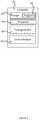
- FIG. 2schematically illustrates one example of the base station receiver apparatus 30.
- the receiver apparatus 30comprises an antenna array 36 comprising a plurality of antenna elements 32A, 32B, 32C which receive respective radio signals 50A, 50B, 50C transmitted from the mobile apparatus 10. Although three antenna elements are shown, three is the minimum and the embodiments described here may include more.
- Each of the plurality of antenna elements 32A, 32B, 32Cis connected to a switch 19, which is controllable by a controller 31 as described below.
- the switch 19is controlled so that only one of the antenna elements 32A, 32B, 32C is connected to an amplifier 21, such as a low noise amplifier or LNA, at a given time.
- the output of the amplifier 21is received at a mixer arrangement 22.
- Thisis provided with in-phase (I) and quadrature (Q) signals by an arrangement of a local oscillator 23, which may be analogue or digital, and a 90° phase shifter 24.
- a sampler 25is configured to receive I and Q output signals from the mixer arrangement and take digital samples thereof.
- the sampler 25may take any suitable form, for instance including two analogue to digital converter (ADC) channels, one for the I channel and one for the Q channel.
- ADCanalogue to digital converter
- the effect of the mixer arrangement 24 and the sampler 25is to downconvert the received signals and to provide digital I and Q samples of the downmixed signals.
- the sampler 25is coupled to a controller 31.
- the controller 31will now be discussed with reference to Figure 3 .
- the controller 31is configured to control the other components of the base station apparatus 30.
- the controllermay take any suitable form. For instance, it may comprise processing circuitry 40, including one or more processors, and a suitable storage device 33, comprising a single memory unit or a plurality of memory units.
- the storage device 33may comprise memory units of different types.
- the storage device 33may store computer program instructions 34 that, when loaded into processing circuitry 40, control the operation of the base station 30.
- the computer program instructions 34may provide the logic and routines that enables the apparatus to perform the functionality described above.
- the computer program instructions 34may arrive at the apparatus 30 via an electromagnetic carrier signal or be copied from a physical entity such as a computer program product, a memory device or a record medium such as a CD-ROM or DVD.
- the processing circuitry 40may be any type of processing circuitry.
- the processing circuitry 40may be a programmable processor that interprets computer program instructions 34 and processes data.
- the processing circuitry 40may include plural programmable processors.
- the processing circuitry 40may be, for example, programmable hardware with embedded firmware.
- the processing circuitry 40may be a single integrated circuit or a set of integrated circuits (i.e. a chipset).
- the processing circuitry 40may also be a hardwired, application-specific integrated circuit (ASIC).
- ASICapplication-specific integrated circuit
- the processing circuitry 40is connected to write to and read from the storage device 33.
- the storage device 33may be a single memory unit or a plurality of memory units.
- the storage device 33may consist of portions of non-volatile storage and volatile storage such as RAM, ROM or FLASH or the like.
- the memory 33may be implemented as a component, or it may be implemented as one or more separate components. Some or all of the components may be integrated/removable and/or may provide permanent/semi-permanent/ dynamic/cached storage.
- the controller 31operates to control the switch 19 to connect the antenna elements 32A, 32B, 32C to the amplifier 21 in turn.
- the controller 31controls the switch 19 to connect one of the antenna elements 32A, 32B, 32C to the Low Noise Amplifier (LNA) 21 for the duration of transmission of the header of a packet transmitted by the mobile device 10.
- LNALow Noise Amplifier
- the controller 31controls the switch 19 to connect a different one of the antenna elements 32A, 32B, 32C to the LNA 21 in a sequence.
- the interval between successive switching of the switch 19is approximately equal to the symbol rate used in the payload of the transmitted packets.
- An output of the controller 31is provided to both a demodulator 26 and a message former 27.
- the demodulator 26is configured to demodulate data modulated onto signals received by the antenna elements 32A, 32B, 32C and extract therefrom an identifier relating to a mobile tag that transmitted the received signals. This identifier is provided to the message former 27.
- the controller 31further comprises a time reference 41, for instance a clock.
- the controller 31further operates to control a Power Management Unit (PMU) 39, which is external to the controller.
- PMUPower Management Unit
- the PMU 39is coupled selectively to provide electrical power to the receiver circuit 37.
- the receiver circuit 37comprises the switch 19, the LNA 21, the mixer 22, the sampler 25, the oscillator 23, and the phase shifter 24.
- the PMU 39is further coupled selectively to provide electrical power to at least the message former 27.
- the PMU 39comprises an internal switching circuit.
- the PMU 39is configured to provide power to particular devices when instructed to do so by the controller 31.
- the base station 30may be coupled to the server (not shown) via an Ethernet cable.
- the base station 30here may be powered by power-over-Ethernet.
- the controller 31comprises a random number generator 38.
- the random number generator 38is configured to generate an integer at random to be used by the processing circuitry 40.
- the random integeris in the range o milliseconds to round d max L p , where d max is the maximum delay time.
- the maximum delay timeis typically 5 milliseconds, where 5 milliseconds is equivalent to the time it takes to process a positioning packet.
- the message former 27may be integrated within the controller 31.
- the message former 27is configured to generate a message comprising I and Q samples of the downconverted signals from each of the antenna elements 32A, 32B, 32C and the identifier. The message is then passed to a transmitter 28, from where it is transmitted.
- the transmitteris incorporated within an Ethernet integrated circuit (chip) 29.
- the messagemay be transmitted via an Ethernet cable, to a central server for instance.
- the messagemay be transmitted wirelessly, for instance using radio signals.
- the radio signalsmay have a transmission range of 100 meters or less.
- the radio frequency signalsmay be 802.11 wireless local area network (WLAN) signals, Bluetooth or Bluetooth Low Energy signals, Ultra wideband (UWB) signals or Zigbee signals.
- the messagemay transmitted (e.g. broadcast) such that it can be received directly by the mobile telephone 10.
- the messagemay be transmitted or broadcast such that it can be received by a server (not shown).
- the servercan be configured to perform the step of calculating a bearing from the base station 30 to the mobile device 10, and calculating the location of the mobile device.
- the messagemay be relayed by a device, for instance another base station receiver apparatus 30, before it reaches the destination of the mobile station 10 or the server.
- a devicefor instance another base station receiver apparatus 30, before it reaches the destination of the mobile station 10 or the server.
- the messagemay include plural positioning packets, each including a header and a payload.
- the headers of the packetsinclude an identifier relating to and identifying the base station receiver apparatus 30.
- the payloadsinclude the I and Q samples and the identifier demodulated from the signals received by the base station receiver apparatus 30.
- the I and Q samples and identifier relating to one signal received at the base station receiver apparatus 30may be included in one positioning packet, or split across multiple positioning packets.
- One positioning packetmay include I and Q samples and identifiers relating to two or more signals received at the base station receiver apparatus 30, although advantageously each packet relates to only one signal.
- each antenna element 32Ais sampled twice although one antenna element (a reference element) is sampled more frequently. Performing three measurements results in 104 samples which, with one byte for each I and Q sample, totals 208 bytes of data. These bytes are included in the message.
- the I and Q samplesconstitute complex signal parameters in that the I and Q samples together define parameters of a complex signal.
- the controller 31may process the I and Q samples to provide other complex signal parameters relating to the received signals, from which bearing calculation can be performed. For instance, the controller 31 may provide averaging of the I and Q samples in the angle/phase domain before converting the averages back to the I and Q domain (one sample for each antenna) and providing the averaged samples as complex signal parameters. Alternatively, the controller 31 may calculate amplitude and/or phase information from the I and Q samples, and provide the amplitude, phase or phase and amplitude information as complex signal parameters
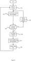
- Figure 4is a flow chart illustrating operation of the receiver apparatus 30 according to aspects of the invention.
- the receiver circuit 37is activated in step 200. Sometime thereafter, a mobile device 10 transmits a positioning packet, which is incident on the base station receiver 30.
- the positioning packetincludes a header and a payload.
- the headeris received and decoded. This utilises only one of the antenna elements 32A-C. Sampling of the payload to obtain I and Q samples from different antenna elements 32A-C involves switching the switch 19 between the antenna elements 32A-C in sequence.
- step 202a first sample of the positioning packet payload is taken using a first antenna element 32A.
- step 208it is determined whether all the necessary samples have been made. This step only produces a positive result when all the antenna elements have been sampled at least twice. On a negative result, the method proceeds to step 204.
- the controller 31operates to control the switch 19 to connect a different one of the antenna elements 32A-C to the LNA 21.
- step 204the method returns to step 202, where a further sample of the positioning packet payload is taken. This time, a second antenna element 32B is used because switching has taken place.
- the methodremains in a loop of steps 202 and 204 until step 208 yields a positive result.
- the at least three antenna elements 32A, 32B, 32Care controlled to be connected by the switch 19 to the LNA 21 in turn.
- the controller 31controls the switch 19 to connect a different one of the antenna elements 32A, 32B, 32C to the LNA 21 in any suitable sequence.
- the interval between successive switching of the switch 19is approximately equal to the symbol rate used in the payload of the transmitted packets.
- step 208yields a positive determination
- the receiver circuit 37is deactivated in step 210. This involves the controller 31 controlling the PMU 39 to cease providing electrical power to the receiver circuit 37.
- step 212the positioning packet is processed. Processing comprises transferring the I and Q samples from the chip comprising the analogue to digital converter to the Ethernet chip 29, and then for transferring that packet out. Processing also comprises message forming using the message former 27. Processing may also comprise the bearing calculation or beamforming.
- the receiver circuit 37is controlled by the controller 31, through the PMU 39, to remain off or deactivated for a further period of time.
- This period of timeis referred to herein as the delay time.
- the delay timemay be randomly or pseudo-randomly generated, or it may be a predetermined delay time.
- the delay timeis typically between 0 and 5 milliseconds.
- the controller 31reactivates the receiver circuit 37 in step 200. This is effected by the controller controlling the PMU 39 to provide electrical power to the receiver circuit 37.
- the value for the delay timeis provided by the time generator 38.
- the controller 31may not have a random time generator 38 but has a fixed delay time preprogrammed, for instance by being stored in the memory 33.
- the fixed delay timemay be different for every base station apparatus 30.
- the fixed delay timemay be preconfigured by the device manufacturer.
- the fixed delay timemay be transmitted to the base station apparatus 30 after installation. Transmission of the fixed delay time to the base station apparatus 30 after installation may occur when the base station apparatus 30 is first initialised or following power-up, for instance.
- Figure 5shows graphically the effect of the implementation of the method of Figure 4 .
- Individual positioning packets 400a-e, 402a-e, 406a-e, and 408a-eare transmitted at intervals by the mobile devices 10.
- Each collection of positioning packets e.g. 400a-erepresent individual mobile devices 10.
- Each mobile device 10may transmit positioning packets at regular intervals or at intervals that are not strictly regular.
- Intervals 410, 412, 414, and 416are the periods of time in which the base station 30 receiver circuits 37 are switched off.
- Intervals 410 and 414represent a first base station, and intervals 412 and 416 represent a second base station.
- the positioning packetsare only received by the base station 30 when it is switched on. It takes a finite period of time to receive a positioning packet 400a. If a second positioning packet is incident on the antenna elements whilst the first positioning packet is being received, a collision will occur and the first positioning packet will be discarded.
- the positioning packet 400a immediately prior to each period of deactivation 410, 412, 414, 416is the positioning packet that has been received and will be subsequently processed by the base station 30. Once the positioning packet 400a is received, the base station 30 receiver circuit 37 is switched off. For example, in the no additional delay example it can be seen that positioning packets 402a-e are never received by a base station 30.
- first and second base stations BS1 and BS2are located nearby to one another.
- the base station 30 receiver circuit 37receive the same positioning packet and then are switched off for the amount of time it takes to process the positioning packet payload.
- the base stations 30then wake up at the same time, and thus receive the same positioning packets. Significantly, they also both miss the same positioning packets (packets are missed if they are transmitted whilst the base stations are processing another positioning packet).
- the no additional delay example shown at the top of the Figureis not part of the invention.
- the example shown at the bottom of the Figureis part of the invention.
- the no additional delay exampleis provided purely as a comparison against examples, including that at the bottom of the Figure, that are within the scope of the invention.
- the base station 30 receiver circuits 37are switched off for the amount of time it takes to process the positioning packet payload and a further delay time. As a result of this further delay time, all positioning packets 400a-e - 408a-e are received by one of the two base stations 30. As such, positioning information can be calculated for each of the mobile devices 10. This is a result of the adding of the further delay time before switching on the receiver circuits 37. Particularly, this is a result of adding a delay that is different or likely to be different for neighbouring base stations 30.
- the delay timeis random, which ensures that the delay time is different for neighbouring base stations almost every time.
- the delay timeis preprogrammed in each base station 30. By ensuring that neighbouring base stations are preprogrammed with different delay times, it can be assured that neighbouring base stations will power up after receiving a given positioning packet at different times.
- the delay timehas a component that is preprogrammed and a component that is random. This helps to ensure different delay times for neighbouring base stations 30.
- the receiver circuit 37is not switched off during the processing period and the delay period. In these embodiments, newly received positioning packets are ignored by the processor such that the packets currently being processed are not overwritten in memory.
- the ADC 25may be disabled or a memory controller (not shown) may be configured not to record samples provided by the ADC. These embodiments comprise deactivation of the receiver circuit 37 without requiring it to power down.
- the method abovecomprises receiving a data packet at a positioning device.
- the packetis begun to be received at step 200 of Figure 4 .
- a receiver circuit of the positioning deviceis deactivated for a period of time at step 210, the period of time constituting a sum of a time taken by the positioning device to process the data packet and a preconfigured or random delay time.
- the delay timeis applied in step 214.
- the packetis processed according to step 212 by: obtaining complex signal parameters of signals received at each of at least three antenna elements forming part of the positioning device, and extracting an identifier from the data packet.
- Obtaining complex signal parametersis multiple executions of step 202.
- the receiver circuit of the positioning deviceis activated again immediately subsequent the period of time.
- the base station apparatus 30may be powered by a fixed mains electricity source.
- the base station apparatus 30may be battery powered.
- references to 'computer-readable storage medium', 'computer program product', 'tangibly embodied computer program' etc. or a 'controller', 'computer', 'processor' etc.should be understood to encompass not only computers having different architectures such as single /multi- processor architectures and sequential (Von Neumann)/parallel architectures but also specialised circuits such as field-programmable gate arrays (FPGA), application specific circuits (ASIC), signal processing devices and other devices.
- References to computer program, instructions, code etc.should be understood to encompass software for a programmable processor or firmware such as, for example, the programmable content of a hardware device whether instructions for a processor, or configuration settings for a fixed function device, gate array or programmable logic device etc.
Landscapes
- Engineering & Computer Science (AREA)
- Computer Networks & Wireless Communication (AREA)
- Signal Processing (AREA)
- Physics & Mathematics (AREA)
- General Physics & Mathematics (AREA)
- Radar, Positioning & Navigation (AREA)
- Remote Sensing (AREA)
- Theoretical Computer Science (AREA)
- General Engineering & Computer Science (AREA)
- Computer Security & Cryptography (AREA)
- Computer Hardware Design (AREA)
- Computing Systems (AREA)
- Mobile Radio Communication Systems (AREA)
- Health & Medical Sciences (AREA)
- Computer Vision & Pattern Recognition (AREA)
- Artificial Intelligence (AREA)
- Toxicology (AREA)
- General Health & Medical Sciences (AREA)
- Electromagnetism (AREA)
- Position Fixing By Use Of Radio Waves (AREA)
Description
- This invention relates to positioning devices.
- There are a number of known techniques for determining the position of an apparatus using radio frequency signals. Some popular techniques relate to use of the Global Positioning System (GPS), in which multiple satellites orbiting Earth transmit radio frequency signals that enable a GPS receiver to determine its position. However, GPS is often not very effective in determining an accurate position indoors.
- Some non-GPS positioning techniques enable an apparatus to determine its position indoors. However, many of these techniques do not result in an accurate position being determined, and others suffer from other disadvantages.
- An indoor positioning system using positioning receivers that calculate a bearing from which signals are received has been proposed and is described in
WO2012/042315 and some other publications. EP2,261,688 A1 relates to a wireless hardware device for detecting relations of distance to other similar wireless hardware devices and a system for the same.- In accordance with the present invention, there is provided a method according to claim 1, computer program code according to claim 12, and apparatus according to claim 13.
- For a better understanding of various embodiments of the present invention reference will now be made by way of example only to the accompanying drawings in which:
Figure 1 illustrates an apparatus according to aspects of the invention receiving radio signals from a transmitter;Figure 2 is a schematic diagram of a receiver apparatus according to aspects of the invention [we are expecting a replacement for this figure, with the chipsets clearly defined]; 2Figure 3 is a schematic diagram of a controller apparatus according to aspects of the invention [this may be changed];Figure 4 is a flow chart illustrating operation of theFigure 2 receiver apparatus according to aspects of the invention; andFigure 5 is a timing diagram of operation of different ones of theFigure 2 receiver.Figure 1 illustrates a person 92 (carrying a mobile radio communications apparatus 10) at aposition 95 on afloor 100 of abuilding 94. Thebuilding 94 could be, for example, a shopping centre or a conference centre.- Abase
station receiver apparatus 30 is positioned at alocation 80 of thebuilding 94. In the illustrated example, thelocation 80 is on the ceiling of the building 94 (i.e. the overhead interior surface) but in other implementations the receiver may be placed elsewhere, such as on a wall or within an under-floor cavity. For reasons that will become apparent, the basestation receiver apparatus 30 can be termed a positioning receiver. - The
location 80 is directly above the point denoted with thereference numeral 70 on thefloor 100 of the building. Thereceiver apparatus 30 is for enabling the position of themobile apparatus 10 to be determined, although that is not necessarily the only function provided by thereceiver apparatus 30. For
part processing samples of the signals; and
forming a message from the part-processed samples;
a deactivating arrangement configured, in response to receiving the signal, to deactivate a receiver circuit of the positioning device for a period of time, the period of time constituting a sum of a time taken by the positioning device to process the signal and a preconfigured or random delay time; and
an activating arrangement configured to activate the receiver circuit of the positioning device immediately subsequent the period of time. - The delay time may be a preconfigured delay time. The delay time of a receiver circuit in a second positioning device may be different to that of the first positioning device.
- The preconfigured delay time may be transmitted to the positioning device after installation.
- The preconfigured delay time may be programmed into the positioning device during manufacture or initial configuration.
- The delay time may be in whole or in part a random delay time.
- The delay time may be a random delay time that may be less than 10 milliseconds, optionally less than 5 milliseconds.
- The signals received at each of at least three antenna elements forming part of the positioning device are Bluetooth low energy signals.
- The processing arrangement may comprise a transmitter arrangement configured to transmit the message.
- The processing arrangement may comprise a transmitter arrangement configured to transmit the complex signal parameters and the identifier to a position calculating device.
- The processing arrangement may be configured to part process the signals by determining a bearing of the transmitting device from the positioning device.
- A third aspect of the invention provides apparatus comprising at least one processor and at least one memory including computer program code, the at least one memory and the computer program code configured to, with the at least one processor, cause the apparatus at least to perform:
- receiving a signal constituting a positioning packet at a positioning device;
- processing the signal by:
- demodulating a header of the positioning packet from the signal;
- extracting an identifier from the header of the positioning packet;
- part processing samples of the signals; and
- forming a message from the part-processed samples;
- in response to receiving the signal, deactivating a receiver circuit of the positioning device for a period of time, the period of time constituting a sum of a time taken by the positioning device to process the signal and a preconfigured or random delay time; and
- activating the receiver circuit of the positioning device immediately subsequent the period of time.
- A fourth aspect of the invention provides a computer readable medium having stored thereon machine readable instructions that when executed by computing apparatus of a positioning device control it to perform a method comprising:
- receiving a signal constituting a positioning packet at the positioning device;
- processing the signal by:
- demodulating a header of the positioning packet from the signal;
- extracting an identifier from the header of the positioning packet;
- part processing samples of the signals; and
- forming a message from the part-processed samples;
- in response to receiving the signal, deactivating a receiver circuit of the positioning device for a period of time, the period of time constituting a sum of a time taken by the positioning device to process the signal and a preconfigured or random delay time; and
- activating the receiver circuit of the positioning device immediately subsequent the period of time.
- For a better understanding of various embodiments of the present invention reference will now be made by way of example only to the accompanying drawings in which:
Figure 1 illustrates an apparatus according to aspects of the invention receiving radio signals from a transmitter;Figure 2 is a schematic diagram of a receiver apparatus according to aspects of the invention [we are expecting a replacement for this figure, with the chipsets clearly defined];Figure 3 is a schematic diagram of a controller apparatus according to aspects of the invention [this may be changed];Figure 4 is a flow chart illustrating operation of theFigure 2 receiver apparatus according to aspects of the invention; andFigure 5 is a timing diagram of operation of different ones of theFigure 2 receiver.Figure 1 illustrates a person 92 (carrying a mobile radio communications apparatus 10) at aposition 95 on afloor 100 of abuilding 94. Thebuilding 94 could be, for example, a shopping centre or a conference centre.- A base
station receiver apparatus 30 is positioned at alocation 80 of thebuilding 94. In the illustrated example, thelocation 80 is on the ceiling of the building 94 (i.e. the overhead interior surface) but in other implementations the receiver may be placed elsewhere, such as on a wall or within an under-floor cavity. For reasons that will become apparent, the basestation receiver apparatus 30 can be termed a positioning receiver. - The
location 80 is directly above the point denoted with thereference numeral 70 on thefloor 100 of the building. Thereceiver apparatus 30 is for enabling the position of themobile apparatus 10 to be determined, although that is not necessarily the only function provided by thereceiver apparatus 30. For example, thereceiver apparatus 30 may be part of a transceiver for providing wireless internet access to users ofmobile apparatuses 10, for example, via Bluetooth Low Energy (BT LE) protocol signals or wireless local area network (WLAN) radio signals. - Briefly, the
mobile device 10 transmits signals in the form of positioning packets which are received at the basestation receiver apparatus 30. Themobile device 10 is operable to transmit radio signals that are receivable by thebase station 30, for instance Bluetooth Low Energy protocol signals. The basestation receiver apparatus 30 takes I and Q samples, and transmits them to a bearing calculation apparatus for processing. - The bearing calculation apparatus may be the
mobile device 10, a server apparatus (not shown) that is separate from themobile device 10, or by another basestation receiver apparatus 30, for instance. The bearing calculation apparatus then uses the received samples to estimate a bearing of themobile device 10 from the basestation receiver apparatus 30. From the bearing, the bearing calculation apparatus may calculate the location of themobile device 10. Bearings from themobile device 10 to plural basestation receiver apparatuses 30 can be used to improve the accuracy of the location determination. - Alternatively, a mobile tag other than the
mobile device 10 may transmit signals which are received by the basestation receiver apparatus 30, and the bearing calculation apparatus may use I and Q samples of these signals to calculate a bearing of the mobile tag from the basestation receiver apparatus 30. Here, themobile tag 10 may be absent of a receiver. A mobile tag is absent of voice communication capability, and may also be absent of a display and audio transducers. - The
position 95 of theperson 92 is defined by specifying a position along a bearing 82 which runs from thelocation 80 of thereceiver apparatus 30 through thelocation 95 of themobile apparatus 10. The bearing 82 is defined by an elevation angle θ and an azimuth angle ϕ. - The
mobile apparatus 10 may, for example, be a hand portable electronic device such as a mobile radiotelephone. Themobile apparatus 10 may transmitradio signals 50 periodically as beacons. - The radio signals may, for example, have a transmission range of 100 meters or less. For example, the radio signals may be 802.11 wireless local area network (WLAN) signals, Bluetooth signals, Ultra wideband (UWB) signals or Zigbee signals.
Figure 2 schematically illustrates one example of the basestation receiver apparatus 30. Thereceiver apparatus 30 comprises anantenna array 36 comprising a plurality ofantenna elements respective radio signals mobile apparatus 10. Although three antenna elements are shown, three is the minimum and the embodiments described here may include more.- Each of the plurality of
antenna elements switch 19, which is controllable by acontroller 31 as described below. Theswitch 19 is controlled so that only one of theantenna elements amplifier 21, such as a low noise amplifier or LNA, at a given time. The output of theamplifier 21 is received at amixer arrangement 22. This is provided with in-phase (I) and quadrature (Q) signals by an arrangement of alocal oscillator 23, which may be analogue or digital, and a 90°phase shifter 24. Asampler 25 is configured to receive I and Q output signals from the mixer arrangement and take digital samples thereof. Thesampler 25 may take any suitable form, for instance including two analogue to digital converter (ADC) channels, one for the I channel and one for the Q channel. The effect of themixer arrangement 24 and thesampler 25 is to downconvert the received signals and to provide digital I and Q samples of the downmixed signals. - The
sampler 25 is coupled to acontroller 31. Thecontroller 31 will now be discussed with reference toFigure 3 . - The
controller 31 is configured to control the other components of thebase station apparatus 30. The controller may take any suitable form. For instance, it may comprise processingcircuitry 40, including one or more processors, and asuitable storage device 33, comprising a single memory unit or a plurality of memory units. Thestorage device 33 may comprise memory units of different types. Thestorage device 33 may storecomputer program instructions 34 that, when loaded intoprocessing circuitry 40, control the operation of thebase station 30. Thecomputer program instructions 34 may provide the logic and routines that enables the apparatus to perform the functionality described above. Thecomputer program instructions 34 may arrive at theapparatus 30 via an electromagnetic carrier signal or be copied from a physical entity such as a computer program product, a memory device or a record medium such as a CD-ROM or DVD. - The
processing circuitry 40 may be any type of processing circuitry. For example, theprocessing circuitry 40 may be a programmable processor that interpretscomputer program instructions 34 and processes data. Theprocessing circuitry 40 may include plural programmable processors. Alternatively, theprocessing circuitry 40 may be, for example, programmable hardware with embedded firmware. Theprocessing circuitry 40 may be a single integrated circuit or a set of integrated circuits (i.e. a chipset). Theprocessing circuitry 40 may also be a hardwired, application-specific integrated circuit (ASIC). The processing circuitry may be termed processing means. - The
processing circuitry 40 is connected to write to and read from thestorage device 33. Thestorage device 33 may be a single memory unit or a plurality of memory units. Thestorage device 33 may consist of portions of non-volatile storage and volatile storage such as RAM, ROM or FLASH or the like. Thememory 33 may be implemented as a component, or it may be implemented as one or more separate components. Some or all of the components may be integrated/removable and/or may provide permanent/semi-permanent/ dynamic/cached storage. - The
controller 31 operates to control theswitch 19 to connect theantenna elements amplifier 21 in turn. Thecontroller 31 controls theswitch 19 to connect one of theantenna elements mobile device 10. After the header has been received, thecontroller 31 controls theswitch 19 to connect a different one of theantenna elements LNA 21 in a sequence. The interval between successive switching of theswitch 19 is approximately equal to the symbol rate used in the payload of the transmitted packets. - An output of the
controller 31 is provided to both ademodulator 26 and a message former 27. Thedemodulator 26 is configured to demodulate data modulated onto signals received by theantenna elements - The
controller 31 further comprises atime reference 41, for instance a clock. - The
controller 31 further operates to control a Power Management Unit (PMU) 39, which is external to the controller. - The
PMU 39 is coupled selectively to provide electrical power to thereceiver circuit 37. Thereceiver circuit 37 comprises theswitch 19, theLNA 21, themixer 22, thesampler 25, theoscillator 23, and thephase shifter 24. - The
PMU 39 is further coupled selectively to provide electrical power to at least the message former 27. - The
PMU 39 comprises an internal switching circuit. ThePMU 39 is configured to provide power to particular devices when instructed to do so by thecontroller 31. - The
base station 30 may be coupled to the server (not shown) via an Ethernet cable. Thebase station 30 here may be powered by power-over-Ethernet. - In this embodiment, the
controller 31 comprises arandom number generator 38. Therandom number generator 38 is configured to generate an integer at random to be used by theprocessing circuitry 40. Theprocessing circuitry 40 is configured to use the random number to generate a delay time, as follows:

- The message former 27 may be integrated within the
controller 31. - The message former 27 is configured to generate a message comprising I and Q samples of the downconverted signals from each of the
antenna elements transmitter 28, from where it is transmitted. The transmitter is incorporated within an Ethernet integrated circuit (chip) 29. The message may be transmitted via an Ethernet cable, to a central server for instance. - Alternatively the message may be transmitted wirelessly, for instance using radio signals. The radio signals may have a transmission range of 100 meters or less. For example, the radio frequency signals may be 802.11 wireless local area network (WLAN) signals, Bluetooth or Bluetooth Low Energy signals, Ultra wideband (UWB) signals or Zigbee signals. Here, the message may transmitted (e.g. broadcast) such that it can be received directly by the
mobile telephone 10. Alternatively, the message may be transmitted or broadcast such that it can be received by a server (not shown). The server can be configured to perform the step of calculating a bearing from thebase station 30 to themobile device 10, and calculating the location of the mobile device. - However it is communicated, the message may be relayed by a device, for instance another base
station receiver apparatus 30, before it reaches the destination of themobile station 10 or the server. - The message may include plural positioning packets, each including a header and a payload. The headers of the packets include an identifier relating to and identifying the base
station receiver apparatus 30. The payloads include the I and Q samples and the identifier demodulated from the signals received by the basestation receiver apparatus 30. The I and Q samples and identifier relating to one signal received at the basestation receiver apparatus 30 may be included in one positioning packet, or split across multiple positioning packets. One positioning packet may include I and Q samples and identifiers relating to two or more signals received at the basestation receiver apparatus 30, although advantageously each packet relates to only one signal. - In a prototype system constructed by the inventors, sixteen
antenna elements 32A are used. In this system, each antenna element is sampled twice although one antenna element (a reference element) is sampled more frequently. Performing three measurements results in 104 samples which, with one byte for each I and Q sample, totals 208 bytes of data. These bytes are included in the message. - The I and Q samples constitute complex signal parameters in that the I and Q samples together define parameters of a complex signal.
- Instead of transmitting 'raw' I and Q samples, the
controller 31 may process the I and Q samples to provide other complex signal parameters relating to the received signals, from which bearing calculation can be performed. For instance, thecontroller 31 may provide averaging of the I and Q samples in the angle/phase domain before converting the averages back to the I and Q domain (one sample for each antenna) and providing the averaged samples as complex signal parameters. Alternatively, thecontroller 31 may calculate amplitude and/or phase information from the I and Q samples, and provide the amplitude, phase or phase and amplitude information as complex signal parameters - Whatever form is taken by the complex signal parameters, they are included in a message as described above.
Figure 4 is a flow chart illustrating operation of thereceiver apparatus 30 according to aspects of the invention.- The
receiver circuit 37 is activated instep 200. Sometime thereafter, amobile device 10 transmits a positioning packet, which is incident on thebase station receiver 30. The positioning packet includes a header and a payload. The header is received and decoded. This utilises only one of theantenna elements 32A-C. Sampling of the payload to obtain I and Q samples fromdifferent antenna elements 32A-C involves switching theswitch 19 between theantenna elements 32A-C in sequence. - In
step 202, a first sample of the positioning packet payload is taken using afirst antenna element 32A. Atstep 208, it is determined whether all the necessary samples have been made. This step only produces a positive result when all the antenna elements have been sampled at least twice. On a negative result, the method proceeds to step 204. Here, thecontroller 31 operates to control theswitch 19 to connect a different one of theantenna elements 32A-C to theLNA 21. Afterstep 204, the method returns to step 202, where a further sample of the positioning packet payload is taken. This time, asecond antenna element 32B is used because switching has taken place. - The method remains in a loop of
steps step 208 yields a positive result. In the loop, the at least threeantenna elements switch 19 to theLNA 21 in turn. Thecontroller 31 controls theswitch 19 to connect a different one of theantenna elements LNA 21 in any suitable sequence. The interval between successive switching of theswitch 19 is approximately equal to the symbol rate used in the payload of the transmitted packets. - Once
step 208 yields a positive determination, thereceiver circuit 37 is deactivated instep 210. This involves thecontroller 31 controlling thePMU 39 to cease providing electrical power to thereceiver circuit 37. Then, instep 212 the positioning packet is processed. Processing comprises transferring the I and Q samples from the chip comprising the analogue to digital converter to the Ethernet chip 29, and then for transferring that packet out. Processing also comprises message forming using the message former 27. Processing may also comprise the bearing calculation or beamforming. - Once the processing of
step 212 is complete, thereceiver circuit 37 is controlled by thecontroller 31, through thePMU 39, to remain off or deactivated for a further period of time. This period of time is referred to herein as the delay time. The delay time may be randomly or pseudo-randomly generated, or it may be a predetermined delay time. The delay time is typically between 0 and 5 milliseconds. - After the delay time has passed, in the
controller 31 reactivates thereceiver circuit 37 instep 200. This is effected by the controller controlling thePMU 39 to provide electrical power to thereceiver circuit 37. - In embodiments in which the delay time is be randomly or pseudo-randomly generated, the value for the delay time is provided by the
time generator 38. - In embodiments in which the delay time is predetermined, the
controller 31 may not have arandom time generator 38 but has a fixed delay time preprogrammed, for instance by being stored in thememory 33. The fixed delay time may be different for everybase station apparatus 30. The fixed delay time may be preconfigured by the device manufacturer. Alternatively, the fixed delay time may be transmitted to thebase station apparatus 30 after installation. Transmission of the fixed delay time to thebase station apparatus 30 after installation may occur when thebase station apparatus 30 is first initialised or following power-up, for instance. Figure 5 shows graphically the effect of the implementation of the method ofFigure 4 .Individual positioning packets 400a-e, 402a-e, 406a-e, and 408a-e are transmitted at intervals by themobile devices 10. Each collection of positioning packets e.g. 400a-e represent individualmobile devices 10. Eachmobile device 10 may transmit positioning packets at regular intervals or at intervals that are not strictly regular.Intervals base station 30receiver circuits 37 are switched off.Intervals intervals base station 30 when it is switched on. It takes a finite period of time to receive apositioning packet 400a. If a second positioning packet is incident on the antenna elements whilst the first positioning packet is being received, a collision will occur and the first positioning packet will be discarded.- The
positioning packet 400a immediately prior to each period ofdeactivation base station 30. Once thepositioning packet 400a is received, thebase station 30receiver circuit 37 is switched off. For example, in the no additional delay example it can be seen thatpositioning packets 402a-e are never received by abase station 30. - In the no additional delay example shown at the top of the Figure, first and second base stations BS1 and BS2 are located nearby to one another. The
base station 30receiver circuit 37 receive the same positioning packet and then are switched off for the amount of time it takes to process the positioning packet payload. Thebase stations 30 then wake up at the same time, and thus receive the same positioning packets. Significantly, they also both miss the same positioning packets (packets are missed if they are transmitted whilst the base stations are processing another positioning packet). The no additional delay example shown at the top of the Figure is not part of the invention. The example shown at the bottom of the Figure is part of the invention. The no additional delay example is provided purely as a comparison against examples, including that at the bottom of the Figure, that are within the scope of the invention. - In the illustrated example that is part of the present invention, the
base station 30receiver circuits 37 are switched off for the amount of time it takes to process the positioning packet payload and a further delay time. As a result of this further delay time, all positioningpackets 400a-e - 408a-e are received by one of the twobase stations 30. As such, positioning information can be calculated for each of themobile devices 10. This is a result of the adding of the further delay time before switching on thereceiver circuits 37. Particularly, this is a result of adding a delay that is different or likely to be different for neighbouringbase stations 30. - In some embodiments, the delay time is random, which ensures that the delay time is different for neighbouring base stations almost every time. In other embodiments the delay time is preprogrammed in each
base station 30. By ensuring that neighbouring base stations are preprogrammed with different delay times, it can be assured that neighbouring base stations will power up after receiving a given positioning packet at different times. In other embodiments, the delay time has a component that is preprogrammed and a component that is random. This helps to ensure different delay times for neighbouringbase stations 30. - Of course, different delay times result in different power up times if the processing period is the same for different base stations (any difference in the time at which a positioning packet starts to be received is negligible).
- An alternative solution to the problem of ensuring that positioning packets are received could be provided by providing more sophisticated hardware in the base stations. However, there is considerable advantage in allowing
base stations 30 to be constructed with relatively basic hardware. As well as providing a lower implementation cost for a given installation, it also provides the possibility of increasing the number of base stations in an installation, thus increasing positioning accuracy or reducing time to a position fix, for a given cost. The base station hardware described with reference toFigure 2 can be provided at very low cost. - Various alternatives and variations are conceivable and all such variations and alternatives are within the scope of the invention unless outside the scope of the claims. Some such alternatives will now be described.
- For instance, in other embodiments, the
receiver circuit 37 is not switched off during the processing period and the delay period. In these embodiments, newly received positioning packets are ignored by the processor such that the packets currently being processed are not overwritten in memory. For instance, in these other embodiments, theADC 25 may be disabled or a memory controller (not shown) may be configured not to record samples provided by the ADC. These embodiments comprise deactivation of thereceiver circuit 37 without requiring it to power down. - To paraphrase, the method above comprises receiving a data packet at a positioning device. The packet is begun to be received at
step 200 ofFigure 4 . Upon receiving the data packet, a receiver circuit of the positioning device is deactivated for a period of time atstep 210, the period of time constituting a sum of a time taken by the positioning device to process the data packet and a preconfigured or random delay time. The delay time is applied instep 214. The packet is processed according to step 212 by: obtaining complex signal parameters of signals received at each of at least three antenna elements forming part of the positioning device, and extracting an identifier from the data packet. Obtaining complex signal parameters is multiple executions ofstep 202. The receiver circuit of the positioning device is activated again immediately subsequent the period of time. - In further embodiments, the
base station apparatus 30 may be powered by a fixed mains electricity source. Alternatively, thebase station apparatus 30 may be battery powered. - References to 'computer-readable storage medium', 'computer program product', 'tangibly embodied computer program' etc. or a 'controller', 'computer', 'processor' etc. should be understood to encompass not only computers having different architectures such as single /multi- processor architectures and sequential (Von Neumann)/parallel architectures but also specialised circuits such as field-programmable gate arrays (FPGA), application specific circuits (ASIC), signal processing devices and other devices. References to computer program, instructions, code etc. should be understood to encompass software for a programmable processor or firmware such as, for example, the programmable content of a hardware device whether instructions for a processor, or configuration settings for a fixed function device, gate array or programmable logic device etc.


Claims (15)
- A method comprising:receiving at least one signal (50A,50B,50C) constituting a positioning packet (400a-e,402a-e,406a-e,408a-e) at a positioning device (30);processing the at least one signal (50A,50B,50C) by:demodulating a header of the positioning packet (400a-e,402a-e,406a-e,408a-e) from the at least one signal (50A,50B,50C);extracting an identifier from the header of the positioning packet (400a-e,402a-e,406a-e,408a-e);part processing samples of the at least one signal (50A,50B,50C); andforming a message from the part-processed samples;the method beingcharacterised by:in response to receiving the at least one signal (50A,50B,50C), deactivating a receiver circuit (37) of the positioning device (30) for a period of time, the period of time constituting a sum of a time taken by the positioning device (30) to process the at least one signal (50A,50B,50C) and a delay time, wherein the delay time is a preconfigured delay time or a random delay time; andactivating the receiver circuit (37) of the positioning device (30) immediately subsequent the period of time.
- The method of claim 1, wherein the delay time is the preconfigured delay time.
- The method of claim 2, wherein the delay time of a receiver circuit (37) in a second positioning device (30) is different to that of the first positioning device (30).
- The method of any proceeding claim, wherein the preconfigured delay time is transmitted to the positioning device (30) after installation.
- The method of any of claims 1, 2, or 3, wherein the preconfigured delay time is programmed into the positioning device (30) during manufacture or initial configuration.
- The method of claim 1, wherein the delay time is in whole or in part the random delay time.
- The method of claim 6, wherein the delay time is the random delay time that is less than 10 milliseconds, optionally less than 5 milliseconds.
- The method of any proceeding claim, wherein the at least one signal (50A,50B,50C) received at each of at least three antenna elements (32A,32B,32C) forming part of the positioning device (30) is a Bluetooth low energy signal.
- The method of any proceeding claim, wherein processing further comprises transmitting the message.
- The method of claim 9, wherein processing further comprises transmitting complex signal parameters and the identifier to a position calculating device.
- The method of any of claims 1 to 8, wherein part processing comprises determining a bearing of a transmitting device (10) from the positioning device (30).
- A computer program code comprising machine readable instructions (34) that when executed by computing apparatus (40) cause performance of a method as claimed in any of claims 1 to 11.
- Apparatus comprising means for performing a method as claimed in any of claims 1 to 11.
- Apparatus as claimed in claim 13, wherein the means for performing a method as claimed in any of claims 1 to 11 comprise computer program code (34) as claimed in claim 12.
- A computer readable medium (33) having stored thereon computer program code (34) as claimed in claim 12.
Applications Claiming Priority (1)
| Application Number | Priority Date | Filing Date | Title |
|---|---|---|---|
| PCT/IB2012/054491WO2014033500A1 (en) | 2012-08-31 | 2012-08-31 | Positioning devices |
Publications (3)
| Publication Number | Publication Date |
|---|---|
| EP2891372A1 EP2891372A1 (en) | 2015-07-08 |
| EP2891372A4 EP2891372A4 (en) | 2016-02-17 |
| EP2891372B1true EP2891372B1 (en) | 2017-06-28 |
Family
ID=50182588
Family Applications (1)
| Application Number | Title | Priority Date | Filing Date |
|---|---|---|---|
| EP12883832.3ANot-in-forceEP2891372B1 (en) | 2012-08-31 | 2012-08-31 | Positioning devices |
Country Status (4)
| Country | Link |
|---|---|
| US (1) | US9674652B2 (en) |
| EP (1) | EP2891372B1 (en) |
| CN (1) | CN104756563A (en) |
| WO (1) | WO2014033500A1 (en) |
Families Citing this family (3)
| Publication number | Priority date | Publication date | Assignee | Title |
|---|---|---|---|---|
| US10492145B2 (en) | 2016-02-17 | 2019-11-26 | Nokia Solutions And Networks Oy | Method and apparatus for reducing energy consumption |
| US10361482B2 (en)* | 2016-07-27 | 2019-07-23 | Cisco Technology, Inc. | Dynamic information storage to enable angle-of-arrival smart antennas |
| US10909830B1 (en)* | 2017-11-07 | 2021-02-02 | Pica Product Development, Llc | Personal emergency alert system, method and device |
Family Cites Families (80)
| Publication number | Priority date | Publication date | Assignee | Title |
|---|---|---|---|---|
| US667646A (en) | 1898-09-13 | 1901-02-05 | Louis Bergier | Lining metallic or other vessels or tubes with glass. |
| US2836816A (en) | 1954-05-11 | 1958-05-27 | Itt | Airborne pictorial navigation computer |
| US3746846A (en) | 1971-04-01 | 1973-07-17 | Vega Precision Labor Inc | Polar to rectilinear chart system |
| US3838427A (en) | 1972-07-03 | 1974-09-24 | King Radio Corp | Method and apparatus for digitally indicating direct present position |
| DE2326521A1 (en) | 1973-05-24 | 1974-12-05 | Rohde & Schwarz | ARRANGEMENT FOR THE AUTOMATIC DIRECTION AND LOCATION OF AIRPLANES |
| AU489245B1 (en) | 1973-09-20 | 1976-02-05 | Amalgamated Wireless (Australasia) Limited | Transmitter output specification monitor |
| US4232294A (en) | 1979-04-30 | 1980-11-04 | Control Data Corporation | Method and apparatus for rotating priorities between stations sharing a communication channel |
| JPH05297098A (en) | 1992-04-20 | 1993-11-12 | Casio Comput Co Ltd | Navigation system |
| US5740048A (en) | 1992-08-07 | 1998-04-14 | Abel; Jonathan S. | Method and apparatus for GPS positioning, filtering and integration |
| US5614914A (en) | 1994-09-06 | 1997-03-25 | Interdigital Technology Corporation | Wireless telephone distribution system with time and space diversity transmission for determining receiver location |
| US5844522A (en) | 1995-10-13 | 1998-12-01 | Trackmobile, Inc. | Mobile telephone location system and method |
| US6195046B1 (en) | 1996-06-06 | 2001-02-27 | Klein S. Gilhousen | Base station with slave antenna for determining the position of a mobile subscriber in a CDMA cellular telephone system |
| US5859612A (en) | 1996-06-06 | 1999-01-12 | Qualcomm Incorporated | Method for using an antenna with a rotating beam for determining the position of a mobile subscriber in a CDMA cellular telephone system |
| FI103248B (en) | 1996-10-29 | 1999-05-14 | Nokia Telecommunications Oy | Determination of the position of a terminal equipment in a radio system |
| US6459704B1 (en)* | 1997-08-12 | 2002-10-01 | Spectrum Tracking Systems, Inc. | Method and system for radio-location determination |
| US6217132B1 (en) | 1997-12-02 | 2001-04-17 | Kelsey-Hayes Company | Hydraulic control unit having a master cylinder and anti-lock braking valves integrally mounted therein |
| US6064340A (en) | 1998-07-02 | 2000-05-16 | Intersil Corporation | Electrostatic discharge locating apparatus and method |
| US6321092B1 (en) | 1998-11-03 | 2001-11-20 | Signal Soft Corporation | Multiple input data management for wireless location-based applications |
| EP1247115B1 (en) | 1999-12-15 | 2003-08-06 | United Parcel Service Of America, Inc. | Methods and systems for monitoring multiple channels in a very high frequency omni-directional range receiver |
| WO2001054430A2 (en)* | 2000-01-17 | 2001-07-26 | Qualcomm Incorporated | Wireless communications receiver to facilitate detection of a primary paging channel |
| US6708090B2 (en) | 2000-02-29 | 2004-03-16 | Honeywell International Inc. | Method, apparatus and computer program product for managing line-of-sight communications |
| JP2001308762A (en) | 2000-04-21 | 2001-11-02 | Pioneer Electronic Corp | Receiver for digital broadcasting |
| US6473038B2 (en) | 2001-01-05 | 2002-10-29 | Motorola, Inc. | Method and apparatus for location estimation |
| US20030002471A1 (en) | 2001-03-06 | 2003-01-02 | Crawford James A. | Method for estimating carrier-to-noise-plus-interference ratio (CNIR) for OFDM waveforms and the use thereof for diversity antenna branch selection |
| US6970097B2 (en) | 2001-05-10 | 2005-11-29 | Ge Medical Systems Information Technologies, Inc. | Location system using retransmission of identifying information |
| US7548506B2 (en) | 2001-10-17 | 2009-06-16 | Nortel Networks Limited | System access and synchronization methods for MIMO OFDM communications systems and physical layer packet and preamble design |
| US6608592B2 (en) | 2002-01-18 | 2003-08-19 | Hewlett-Packard Development Company, Lp. | Location system using beacon transmitters |
| US20030162519A1 (en) | 2002-02-26 | 2003-08-28 | Martin Smith | Radio communications device |
| JP4093792B2 (en) | 2002-04-18 | 2008-06-04 | 富士通株式会社 | Positioning system, program and position determining method for determining position of mobile radio station |
| US7764617B2 (en) | 2002-04-29 | 2010-07-27 | Harris Corporation | Mobile ad-hoc network and methods for performing functions therein based upon weighted quality of service metrics |
| US8611919B2 (en) | 2002-05-23 | 2013-12-17 | Wounder Gmbh., Llc | System, method, and computer program product for providing location based services and mobile e-commerce |
| US20060052112A1 (en) | 2002-05-29 | 2006-03-09 | Lior Baussi | Direction finding cell phones |
| AU2002360087A1 (en) | 2002-12-27 | 2004-07-22 | Nokia Corporation | Method for handling location data |
| US7130646B2 (en) | 2003-02-14 | 2006-10-31 | Atheros Communications, Inc. | Positioning with wireless local area networks and WLAN-aided global positioning systems |
| WO2005002070A2 (en) | 2003-03-20 | 2005-01-06 | Bae Systems Information & Electronic Systems Integration Inc. | Correlation interferometer geolocation |
| AU2003901463A0 (en) | 2003-03-31 | 2003-04-17 | Qx Corporation Pty Ltd | A method and device for multipath mitigation in positioning systems using clustered positioning signals |
| GB0325622D0 (en) | 2003-11-03 | 2003-12-10 | Cambridge Consultants | System for determining positional information |
| US7349702B2 (en) | 2003-12-18 | 2008-03-25 | Graumann David L | Self-evolving proximity sensor inclusion-exclusion zones |
| US7116988B2 (en) | 2004-03-16 | 2006-10-03 | Airespace, Inc. | Location of wireless nodes using signal strength weighting metric |
| TWI237453B (en) | 2004-05-11 | 2005-08-01 | Realtek Semiconductor Corp | Method and apparatus for antenna diversity |
| US8032156B2 (en) | 2004-09-07 | 2011-10-04 | Qualcomm Incorporated | Procedure to increase position location availabilty |
| US7403784B2 (en) | 2005-03-10 | 2008-07-22 | Avaya Technology Corp. | Method and apparatus for positioning a set of terminals in an indoor wireless environment |
| DE102005026788A1 (en) | 2005-06-10 | 2006-12-21 | Deutsche Telekom Ag | Method and system for locating a mobile WLAN client |
| TWI271536B (en) | 2005-06-27 | 2007-01-21 | Lite On Technology Corp | Position indicating system |
| GB2443118B (en) | 2005-08-31 | 2010-06-16 | British Telecomm | Personalised heterogeneous network handover alert scheme |
| US8179318B1 (en) | 2005-09-28 | 2012-05-15 | Trueposition, Inc. | Precise position determination using VHF omni-directional radio range signals |
| US7941157B2 (en) | 2005-11-15 | 2011-05-10 | Robert Bosch Gmbh | Hybrid localization in wireless networks |
| JP2007139521A (en) | 2005-11-16 | 2007-06-07 | Canon Inc | Array antenna device |
| US7667646B2 (en) | 2006-02-21 | 2010-02-23 | Nokia Corporation | System and methods for direction finding using a handheld device |
| KR100975744B1 (en)* | 2006-04-13 | 2010-08-12 | 삼성전자주식회사 | Rake receiving apparatus and method in mobile communication system |
| US7576694B2 (en) | 2006-04-20 | 2009-08-18 | Toshiba America Research, Inc. | Secure wireless user localization scheme using transmission range variation |
| EP1863191B1 (en) | 2006-06-02 | 2012-03-14 | STMicroelectronics N.V. | Method for managing eventual interferences with antenna switching and corresponding device |
| US7868760B2 (en) | 2006-06-05 | 2011-01-11 | Bp Corporation North America Inc. | Method for accounting for people in emergencies in industrial settings |
| US7548203B2 (en) | 2006-09-15 | 2009-06-16 | Nokia Corporation | Performance and power management in direction of arrival determination by utilizing sensor information |
| GB2445384A (en) | 2006-10-12 | 2008-07-09 | Nokia Corp | Determining the position of a signal source |
| KR101393674B1 (en) | 2007-01-26 | 2014-05-13 | 인터디지탈 테크날러지 코포레이션 | Method and apparatus for securing location information and access control using the location information |
| US20080191941A1 (en) | 2007-02-12 | 2008-08-14 | Mobileaccess Networks Ltd. | Indoor location determination |
| JP5006097B2 (en) | 2007-04-24 | 2012-08-22 | 京セラ株式会社 | Reception control method and wireless communication apparatus |
| JP4438825B2 (en) | 2007-05-29 | 2010-03-24 | ソニー株式会社 | Arrival angle estimation system, communication apparatus, and communication system |
| US8260324B2 (en) | 2007-06-12 | 2012-09-04 | Nokia Corporation | Establishing wireless links via orientation |
| CN101784909A (en) | 2007-08-14 | 2010-07-21 | 诺基亚公司 | distance estimation |
| US20090082019A1 (en) | 2007-09-24 | 2009-03-26 | Marsico Peter J | Methods, systems, and computer readable media for providing dynamic roaming arbitrage service |
| EP2217942B1 (en) | 2007-10-29 | 2017-03-08 | Nokia Technologies Oy | Indoor positioning system and method |
| US7982671B2 (en) | 2008-04-17 | 2011-07-19 | Broadcom Corporation | Method and system for using a wireless local area network (WLAN) phase shifter for smart antenna beam steering |
| GB0816688D0 (en) | 2008-09-12 | 2008-10-22 | Cambridge Silicon Radio Ltd | Determining relative phase data of a received signal |
| US8515448B2 (en) | 2008-10-07 | 2013-08-20 | Nokia Corporation | Upload and download of position reference data |
| CN101742609A (en) | 2008-11-26 | 2010-06-16 | 三星电子株式会社 | Positioning method based on AOA and terminal moving trajectory in single cell environment |
| US8755476B2 (en) | 2009-02-01 | 2014-06-17 | Qualcomm Incorporated | Apparatus and method for antenna switching diversity in an OFDM system |
| US8723729B2 (en) | 2009-05-26 | 2014-05-13 | Broadcom Corporation | Angle of arrival and/or range estimation within a wireless communication device |
| IT1395644B1 (en) | 2009-05-27 | 2012-10-16 | Bitmanufaktur Gmbh | WIRELESS HARDWARE DEVICE FOR DETECTION OF RELATIONSHIPS, AND MONITORING SYSTEM FOR DISTANCE RELATIONS BETWEEN WIRELESS HARDWARE DEVICES |
| US8554251B2 (en)* | 2009-06-29 | 2013-10-08 | Qualcomm Incorporated | Device, method, and apparatus for offline discontinuous reception (DRX) processing in cellular systems |
| US8526305B2 (en)* | 2009-08-26 | 2013-09-03 | Telefonaktiebolaget L M Ericsson (Publ) | System and methods for reducing power consumed by a base station |
| JP2011089947A (en) | 2009-10-26 | 2011-05-06 | Yamatake Corp | Position detection system and method |
| US9055395B2 (en)* | 2009-11-12 | 2015-06-09 | Cisco Technology, Inc. | Location tracking using response messages identifying a tracked device in a wireless network |
| US20110117924A1 (en)* | 2009-11-18 | 2011-05-19 | Qualcomm Incorporated | Position determination using a wireless signal |
| US20130102252A1 (en) | 2010-04-21 | 2013-04-25 | Eth Zurich | Method for communicating and distance bounding system |
| US8554141B2 (en) | 2010-06-24 | 2013-10-08 | Broadcom Corporation | Method and system for multi-stage device filtering in a bluetooth low energy device |
| JP5884059B2 (en) | 2010-07-16 | 2016-03-15 | パナソニックIpマネジメント株式会社 | Radar equipment |
| WO2012042315A1 (en)* | 2010-09-30 | 2012-04-05 | Nokia Corporation | Positioning |
| US9125165B2 (en)* | 2011-07-29 | 2015-09-01 | Broadcom Corporation | WLAN-based positioning system |
- 2012
- 2012-08-31EPEP12883832.3Apatent/EP2891372B1/ennot_activeNot-in-force
- 2012-08-31CNCN201280076671.5Apatent/CN104756563A/enactivePending
- 2012-08-31USUS14/421,705patent/US9674652B2/ennot_activeExpired - Fee Related
- 2012-08-31WOPCT/IB2012/054491patent/WO2014033500A1/enactiveApplication Filing
Non-Patent Citations (1)
| Title |
|---|
| None* |
Also Published As
| Publication number | Publication date |
|---|---|
| WO2014033500A1 (en) | 2014-03-06 |
| CN104756563A (en) | 2015-07-01 |
| EP2891372A1 (en) | 2015-07-08 |
| US9674652B2 (en) | 2017-06-06 |
| US20150215732A1 (en) | 2015-07-30 |
| EP2891372A4 (en) | 2016-02-17 |
Similar Documents
| Publication | Publication Date | Title |
|---|---|---|
| CN113728578B (en) | System and method for positioning reference signal staggered configuration | |
| US9699586B2 (en) | Configuring a sound system | |
| CN110637489B (en) | Enhanced resource sharing for PRS measurements | |
| US9357353B2 (en) | Positioning | |
| US8948238B2 (en) | Handling complex signal parameters | |
| KR20210003105A (en) | Utilization of DRX/CDRX parameters to save power during OTDOA (OBSERVED TIME DIFFERENCE OF ARRIVAL) session | |
| US9426619B2 (en) | Handling complex signal parameters by a positioning device, and apparatus | |
| CN104041136B (en) | System and method for service discovery | |
| CN107306421B (en) | Positioning method and device | |
| WO2015149581A1 (en) | Positioning method and base station and user equipment for positioning | |
| EP2984501A1 (en) | System and method for channel feedback for location time of flight | |
| WO2013079998A1 (en) | Transmitting service advertisements | |
| WO2019112647A1 (en) | Enhanced time difference of arrival in radio frequency wireless communications | |
| CN112166564A (en) | Limiting positioning reference signal bandwidth in NB-IOT to save power | |
| WO2014051819A1 (en) | Methods and arrangements to communicate environmental information for localization | |
| EP2891372B1 (en) | Positioning devices | |
| US9054856B2 (en) | Processing samples of a received RF signal | |
| WO2025041063A1 (en) | Unlicensed sidelink positioning reference signal transmission and resource allocation |
Legal Events
| Date | Code | Title | Description |
|---|---|---|---|
| PUAI | Public reference made under article 153(3) epc to a published international application that has entered the european phase | Free format text:ORIGINAL CODE: 0009012 | |
| 17P | Request for examination filed | Effective date:20150219 | |
| AK | Designated contracting states | Kind code of ref document:A1 Designated state(s):AL AT BE BG CH CY CZ DE DK EE ES FI FR GB GR HR HU IE IS IT LI LT LU LV MC MK MT NL NO PL PT RO RS SE SI SK SM TR | |
| AX | Request for extension of the european patent | Extension state:BA ME | |
| DAX | Request for extension of the european patent (deleted) | ||
| REG | Reference to a national code | Ref country code:DE Ref legal event code:R079 Ref document number:602012034098 Country of ref document:DE Free format text:PREVIOUS MAIN CLASS: H04W0064000000 Ipc:G01S0001080000 | |
| RA4 | Supplementary search report drawn up and despatched (corrected) | Effective date:20160120 | |
| RIC1 | Information provided on ipc code assigned before grant | Ipc:H04W 4/02 20090101ALI20160114BHEP Ipc:G01S 5/02 20060101ALI20160114BHEP Ipc:H01Q 21/00 20060101ALI20160114BHEP Ipc:G01S 1/08 20060101AFI20160114BHEP | |
| GRAP | Despatch of communication of intention to grant a patent | Free format text:ORIGINAL CODE: EPIDOSNIGR1 | |
| STAA | Information on the status of an ep patent application or granted ep patent | Free format text:STATUS: GRANT OF PATENT IS INTENDED | |
| INTG | Intention to grant announced | Effective date:20170206 | |
| GRAS | Grant fee paid | Free format text:ORIGINAL CODE: EPIDOSNIGR3 | |
| GRAA | (expected) grant | Free format text:ORIGINAL CODE: 0009210 | |
| STAA | Information on the status of an ep patent application or granted ep patent | Free format text:STATUS: THE PATENT HAS BEEN GRANTED | |
| AK | Designated contracting states | Kind code of ref document:B1 Designated state(s):AL AT BE BG CH CY CZ DE DK EE ES FI FR GB GR HR HU IE IS IT LI LT LU LV MC MK MT NL NO PL PT RO RS SE SI SK SM TR | |
| REG | Reference to a national code | Ref country code:GB Ref legal event code:FG4D | |
| REG | Reference to a national code | Ref country code:CH Ref legal event code:EP | |
| REG | Reference to a national code | Ref country code:FR Ref legal event code:PLFP Year of fee payment:6 | |
| REG | Reference to a national code | Ref country code:AT Ref legal event code:REF Ref document number:905354 Country of ref document:AT Kind code of ref document:T Effective date:20170715 | |
| REG | Reference to a national code | Ref country code:IE Ref legal event code:FG4D | |
| REG | Reference to a national code | Ref country code:DE Ref legal event code:R096 Ref document number:602012034098 Country of ref document:DE | |
| REG | Reference to a national code | Ref country code:NL Ref legal event code:FP | |
| PGFP | Annual fee paid to national office [announced via postgrant information from national office to epo] | Ref country code:NL Payment date:20170814 Year of fee payment:6 | |
| PG25 | Lapsed in a contracting state [announced via postgrant information from national office to epo] | Ref country code:GR Free format text:LAPSE BECAUSE OF FAILURE TO SUBMIT A TRANSLATION OF THE DESCRIPTION OR TO PAY THE FEE WITHIN THE PRESCRIBED TIME-LIMIT Effective date:20170929 Ref country code:HR Free format text:LAPSE BECAUSE OF FAILURE TO SUBMIT A TRANSLATION OF THE DESCRIPTION OR TO PAY THE FEE WITHIN THE PRESCRIBED TIME-LIMIT Effective date:20170628 Ref country code:LT Free format text:LAPSE BECAUSE OF FAILURE TO SUBMIT A TRANSLATION OF THE DESCRIPTION OR TO PAY THE FEE WITHIN THE PRESCRIBED TIME-LIMIT Effective date:20170628 Ref country code:FI Free format text:LAPSE BECAUSE OF FAILURE TO SUBMIT A TRANSLATION OF THE DESCRIPTION OR TO PAY THE FEE WITHIN THE PRESCRIBED TIME-LIMIT Effective date:20170628 Ref country code:NO Free format text:LAPSE BECAUSE OF FAILURE TO SUBMIT A TRANSLATION OF THE DESCRIPTION OR TO PAY THE FEE WITHIN THE PRESCRIBED TIME-LIMIT Effective date:20170928 | |
| PGFP | Annual fee paid to national office [announced via postgrant information from national office to epo] | Ref country code:DE Payment date:20170822 Year of fee payment:6 Ref country code:FR Payment date:20170714 Year of fee payment:6 Ref country code:GB Payment date:20170830 Year of fee payment:6 | |
| REG | Reference to a national code | Ref country code:LT Ref legal event code:MG4D | |
| REG | Reference to a national code | Ref country code:AT Ref legal event code:MK05 Ref document number:905354 Country of ref document:AT Kind code of ref document:T Effective date:20170628 | |
| PG25 | Lapsed in a contracting state [announced via postgrant information from national office to epo] | Ref country code:SE Free format text:LAPSE BECAUSE OF FAILURE TO SUBMIT A TRANSLATION OF THE DESCRIPTION OR TO PAY THE FEE WITHIN THE PRESCRIBED TIME-LIMIT Effective date:20170628 Ref country code:LV Free format text:LAPSE BECAUSE OF FAILURE TO SUBMIT A TRANSLATION OF THE DESCRIPTION OR TO PAY THE FEE WITHIN THE PRESCRIBED TIME-LIMIT Effective date:20170628 Ref country code:BG Free format text:LAPSE BECAUSE OF FAILURE TO SUBMIT A TRANSLATION OF THE DESCRIPTION OR TO PAY THE FEE WITHIN THE PRESCRIBED TIME-LIMIT Effective date:20170928 Ref country code:RS Free format text:LAPSE BECAUSE OF FAILURE TO SUBMIT A TRANSLATION OF THE DESCRIPTION OR TO PAY THE FEE WITHIN THE PRESCRIBED TIME-LIMIT Effective date:20170628 | |
| PG25 | Lapsed in a contracting state [announced via postgrant information from national office to epo] | Ref country code:RO Free format text:LAPSE BECAUSE OF FAILURE TO SUBMIT A TRANSLATION OF THE DESCRIPTION OR TO PAY THE FEE WITHIN THE PRESCRIBED TIME-LIMIT Effective date:20170628 Ref country code:CZ Free format text:LAPSE BECAUSE OF FAILURE TO SUBMIT A TRANSLATION OF THE DESCRIPTION OR TO PAY THE FEE WITHIN THE PRESCRIBED TIME-LIMIT Effective date:20170628 Ref country code:SK Free format text:LAPSE BECAUSE OF FAILURE TO SUBMIT A TRANSLATION OF THE DESCRIPTION OR TO PAY THE FEE WITHIN THE PRESCRIBED TIME-LIMIT Effective date:20170628 Ref country code:EE Free format text:LAPSE BECAUSE OF FAILURE TO SUBMIT A TRANSLATION OF THE DESCRIPTION OR TO PAY THE FEE WITHIN THE PRESCRIBED TIME-LIMIT Effective date:20170628 Ref country code:AT Free format text:LAPSE BECAUSE OF FAILURE TO SUBMIT A TRANSLATION OF THE DESCRIPTION OR TO PAY THE FEE WITHIN THE PRESCRIBED TIME-LIMIT Effective date:20170628 | |
| PG25 | Lapsed in a contracting state [announced via postgrant information from national office to epo] | Ref country code:PL Free format text:LAPSE BECAUSE OF FAILURE TO SUBMIT A TRANSLATION OF THE DESCRIPTION OR TO PAY THE FEE WITHIN THE PRESCRIBED TIME-LIMIT Effective date:20170628 Ref country code:SM Free format text:LAPSE BECAUSE OF FAILURE TO SUBMIT A TRANSLATION OF THE DESCRIPTION OR TO PAY THE FEE WITHIN THE PRESCRIBED TIME-LIMIT Effective date:20170628 Ref country code:ES Free format text:LAPSE BECAUSE OF FAILURE TO SUBMIT A TRANSLATION OF THE DESCRIPTION OR TO PAY THE FEE WITHIN THE PRESCRIBED TIME-LIMIT Effective date:20170628 Ref country code:IS Free format text:LAPSE BECAUSE OF FAILURE TO SUBMIT A TRANSLATION OF THE DESCRIPTION OR TO PAY THE FEE WITHIN THE PRESCRIBED TIME-LIMIT Effective date:20171028 Ref country code:IT Free format text:LAPSE BECAUSE OF FAILURE TO SUBMIT A TRANSLATION OF THE DESCRIPTION OR TO PAY THE FEE WITHIN THE PRESCRIBED TIME-LIMIT Effective date:20170628 | |
| REG | Reference to a national code | Ref country code:CH Ref legal event code:PL Ref country code:DE Ref legal event code:R097 Ref document number:602012034098 Country of ref document:DE | |
| PG25 | Lapsed in a contracting state [announced via postgrant information from national office to epo] | Ref country code:MC Free format text:LAPSE BECAUSE OF FAILURE TO SUBMIT A TRANSLATION OF THE DESCRIPTION OR TO PAY THE FEE WITHIN THE PRESCRIBED TIME-LIMIT Effective date:20170628 | |
| PG25 | Lapsed in a contracting state [announced via postgrant information from national office to epo] | Ref country code:LI Free format text:LAPSE BECAUSE OF NON-PAYMENT OF DUE FEES Effective date:20170831 Ref country code:CH Free format text:LAPSE BECAUSE OF NON-PAYMENT OF DUE FEES Effective date:20170831 Ref country code:DK Free format text:LAPSE BECAUSE OF FAILURE TO SUBMIT A TRANSLATION OF THE DESCRIPTION OR TO PAY THE FEE WITHIN THE PRESCRIBED TIME-LIMIT Effective date:20170628 | |
| PLBE | No opposition filed within time limit | Free format text:ORIGINAL CODE: 0009261 | |
| REG | Reference to a national code | Ref country code:IE Ref legal event code:MM4A | |
| REG | Reference to a national code | Ref country code:BE Ref legal event code:MM Effective date:20170831 | |
| 26N | No opposition filed | Effective date:20180329 | |
| PG25 | Lapsed in a contracting state [announced via postgrant information from national office to epo] | Ref country code:LU Free format text:LAPSE BECAUSE OF NON-PAYMENT OF DUE FEES Effective date:20170831 | |
| PG25 | Lapsed in a contracting state [announced via postgrant information from national office to epo] | Ref country code:IE Free format text:LAPSE BECAUSE OF NON-PAYMENT OF DUE FEES Effective date:20170831 | |
| PG25 | Lapsed in a contracting state [announced via postgrant information from national office to epo] | Ref country code:BE Free format text:LAPSE BECAUSE OF NON-PAYMENT OF DUE FEES Effective date:20170831 Ref country code:SI Free format text:LAPSE BECAUSE OF FAILURE TO SUBMIT A TRANSLATION OF THE DESCRIPTION OR TO PAY THE FEE WITHIN THE PRESCRIBED TIME-LIMIT Effective date:20170628 | |
| PG25 | Lapsed in a contracting state [announced via postgrant information from national office to epo] | Ref country code:MT Free format text:LAPSE BECAUSE OF NON-PAYMENT OF DUE FEES Effective date:20170831 | |
| REG | Reference to a national code | Ref country code:GB Ref legal event code:732E Free format text:REGISTERED BETWEEN 20190124 AND 20190130 | |
| REG | Reference to a national code | Ref country code:DE Ref legal event code:R119 Ref document number:602012034098 Country of ref document:DE | |
| REG | Reference to a national code | Ref country code:DE Ref legal event code:R081 Ref document number:602012034098 Country of ref document:DE Owner name:PROVENANCE ASSET GROUP LLC, PITTSFORD, US Free format text:FORMER OWNER: NOKIA TECHNOLOGIES OY, ESPOO, FI | |
| REG | Reference to a national code | Ref country code:NL Ref legal event code:MM Effective date:20180901 | |
| GBPC | Gb: european patent ceased through non-payment of renewal fee | Effective date:20180831 | |
| PG25 | Lapsed in a contracting state [announced via postgrant information from national office to epo] | Ref country code:NL Free format text:LAPSE BECAUSE OF NON-PAYMENT OF DUE FEES Effective date:20180901 Ref country code:HU Free format text:LAPSE BECAUSE OF FAILURE TO SUBMIT A TRANSLATION OF THE DESCRIPTION OR TO PAY THE FEE WITHIN THE PRESCRIBED TIME-LIMIT; INVALID AB INITIO Effective date:20120831 | |
| PG25 | Lapsed in a contracting state [announced via postgrant information from national office to epo] | Ref country code:DE Free format text:LAPSE BECAUSE OF NON-PAYMENT OF DUE FEES Effective date:20190301 | |
| PG25 | Lapsed in a contracting state [announced via postgrant information from national office to epo] | Ref country code:FR Free format text:LAPSE BECAUSE OF NON-PAYMENT OF DUE FEES Effective date:20180831 | |
| PG25 | Lapsed in a contracting state [announced via postgrant information from national office to epo] | Ref country code:CY Free format text:LAPSE BECAUSE OF FAILURE TO SUBMIT A TRANSLATION OF THE DESCRIPTION OR TO PAY THE FEE WITHIN THE PRESCRIBED TIME-LIMIT Effective date:20170628 Ref country code:GB Free format text:LAPSE BECAUSE OF NON-PAYMENT OF DUE FEES Effective date:20180831 | |
| PG25 | Lapsed in a contracting state [announced via postgrant information from national office to epo] | Ref country code:MK Free format text:LAPSE BECAUSE OF FAILURE TO SUBMIT A TRANSLATION OF THE DESCRIPTION OR TO PAY THE FEE WITHIN THE PRESCRIBED TIME-LIMIT Effective date:20170628 | |
| PG25 | Lapsed in a contracting state [announced via postgrant information from national office to epo] | Ref country code:TR Free format text:LAPSE BECAUSE OF FAILURE TO SUBMIT A TRANSLATION OF THE DESCRIPTION OR TO PAY THE FEE WITHIN THE PRESCRIBED TIME-LIMIT Effective date:20170628 | |
| PG25 | Lapsed in a contracting state [announced via postgrant information from national office to epo] | Ref country code:PT Free format text:LAPSE BECAUSE OF FAILURE TO SUBMIT A TRANSLATION OF THE DESCRIPTION OR TO PAY THE FEE WITHIN THE PRESCRIBED TIME-LIMIT Effective date:20170628 | |
| PG25 | Lapsed in a contracting state [announced via postgrant information from national office to epo] | Ref country code:AL Free format text:LAPSE BECAUSE OF FAILURE TO SUBMIT A TRANSLATION OF THE DESCRIPTION OR TO PAY THE FEE WITHIN THE PRESCRIBED TIME-LIMIT Effective date:20170628 | |
| STAA | Information on the status of an ep patent application or granted ep patent | Free format text:STATUS: NO OPPOSITION FILED WITHIN TIME LIMIT |