EP2889021A1 - Prewire channel stent - Google Patents
Prewire channel stentDownload PDFInfo
- Publication number
- EP2889021A1 EP2889021A1EP14197293.5AEP14197293AEP2889021A1EP 2889021 A1EP2889021 A1EP 2889021A1EP 14197293 AEP14197293 AEP 14197293AEP 2889021 A1EP2889021 A1EP 2889021A1
- Authority
- EP
- European Patent Office
- Prior art keywords
- balloon
- stent
- channel
- guidewire
- mesh material
- Prior art date
- Legal status (The legal status is an assumption and is not a legal conclusion. Google has not performed a legal analysis and makes no representation as to the accuracy of the status listed.)
- Granted
Links
Images


Classifications
- A—HUMAN NECESSITIES
- A61—MEDICAL OR VETERINARY SCIENCE; HYGIENE
- A61F—FILTERS IMPLANTABLE INTO BLOOD VESSELS; PROSTHESES; DEVICES PROVIDING PATENCY TO, OR PREVENTING COLLAPSING OF, TUBULAR STRUCTURES OF THE BODY, e.g. STENTS; ORTHOPAEDIC, NURSING OR CONTRACEPTIVE DEVICES; FOMENTATION; TREATMENT OR PROTECTION OF EYES OR EARS; BANDAGES, DRESSINGS OR ABSORBENT PADS; FIRST-AID KITS
- A61F2/00—Filters implantable into blood vessels; Prostheses, i.e. artificial substitutes or replacements for parts of the body; Appliances for connecting them with the body; Devices providing patency to, or preventing collapsing of, tubular structures of the body, e.g. stents
- A61F2/95—Instruments specially adapted for placement or removal of stents or stent-grafts
- A61F2/954—Instruments specially adapted for placement or removal of stents or stent-grafts for placing stents or stent-grafts in a bifurcation
- A—HUMAN NECESSITIES
- A61—MEDICAL OR VETERINARY SCIENCE; HYGIENE
- A61F—FILTERS IMPLANTABLE INTO BLOOD VESSELS; PROSTHESES; DEVICES PROVIDING PATENCY TO, OR PREVENTING COLLAPSING OF, TUBULAR STRUCTURES OF THE BODY, e.g. STENTS; ORTHOPAEDIC, NURSING OR CONTRACEPTIVE DEVICES; FOMENTATION; TREATMENT OR PROTECTION OF EYES OR EARS; BANDAGES, DRESSINGS OR ABSORBENT PADS; FIRST-AID KITS
- A61F2/00—Filters implantable into blood vessels; Prostheses, i.e. artificial substitutes or replacements for parts of the body; Appliances for connecting them with the body; Devices providing patency to, or preventing collapsing of, tubular structures of the body, e.g. stents
- A61F2/95—Instruments specially adapted for placement or removal of stents or stent-grafts
- A61F2/958—Inflatable balloons for placing stents or stent-grafts
Definitions
- the present inventionrelates generally to a medical device for the treatment of vascular disease.
- Cardiovascular stentsare widely used in the treatment of vascular diseases.
- stentshave been broadly implanted in vessels to treat vessel narrowing, occlusion, aneurysm, and dissection, among other conditions.
- a typical conventional or known stentcontains a metallic mesh material that is mounted or carried on a deflated balloon.
- In the centre of the balloonis a channel, through which a guidewire can pass to facilitate movement through the arteries; however, there is no channel between the metallic mesh material and the balloon.
- a guidewireis inserted to the vessel and pass the location that needs to be treated and then the cardiovascular stent mounted or carried on a deflated balloon is inserted into the vessel and delivered to the desired location through this guidewire to facilitate movement through the arteries.
- the balloonis inflated to expand and, thereby, deploy the stent to support the artery.
- Vesselshave branches; when narrowing, these narrowed branches are referred to as "bifurcation lesions".
- bifurcation lesionsWhen treating a bifurcation lesion with a conventional or known stent, one guidewire is delivered to the main branch, and another guidewire is delivered to a side branch. These two wires have to be exchanged (which is called wire-exchange) during the operation. This procedure is complicated and time-consuming.
- a typical conventional or known stenthas to be deployed precisely at the desired location.
- some operatorslike to employ the Szabo technique: specifically, they inflate part of the balloon with low pressure, and then deflate the balloon premounted by metallic mesh material to allow the guidewire to pass through the space between the metallic mesh material and the balloon for the precise deployment of the stent.
- this procedurehas a risk of stent dislodgement.
- a method of deploying a stent in a bifurcationincludes introducing two guidewires through the main vessel and using the two guidewires for guiding a dual lumen catheter carrying a stent first to an initial position proximal to the stent deployment position, retracting one wire, and projecting it from the catheter and through a side of the stent a branch guidewire into the second branch vessel, and then moving the catheter to the predetermined deployment position while guided by the main guidewire in the first branch vessel, and the branch guidewire in the second branch vessel.
- the stentis then expanded, and the catheter is removed with the stent remaining in its deployed position
- An alternative embodimentincludes introducing one wire, advancing the system over the one wire and subsequently introducing the second wire.
- US Patent No. 7,771,462 issued August 10, 2010 to Davidson, et al.is of interest for showing the background of this type of invention, and this reference is hereby incorporated herein in its entirety.
- This referencedescribes a designed catheter system comprises a catheter having a catheter body with a distal end, a proximal end, a main vessel guidewire lumen for receiving a main vessel guidewire and a balloon disposing at the distal end of the catheter body.
- the catheterfurther includes a side member that is disposed adjacent to the catheter body.
- the side memberhas a distal end, a proximal end, and a branch vessel guidewire lumen for receiving a branch vessel guidewire.
- a stent having a side holeis disposed over the balloon, and a distal portion of the side member is disposed beneath at least a portion of the stent while being adjacent to and movable with respect to the balloon.
- US Patent No. 8,808,347 issued August 19, 2014 to Bourang et alis of interest for showing alignment of the side branch stent with the main branch stent, and this reference is hereby incorporated herein in its entirety.
- This referencedescribes a system for treating a bifurcation includes a first radially expandable stent and a second radially expandable stent.
- the first stenthas a side hole and a plurality of lateral elements extending from the side hole.
- the second stenthas a plurality of axial elements extending away from the proximal end of the second stent.
- the axial elements of the second stentinterdigitate with the lateral elements of the first stent when both stents have been expanded.
- the device according to the present inventionprovides a prewire channel stent having a structure that includes a balloon having a metallic mesh material outside the balloon, a central passage with ancillary components that inflate or deflate the balloon, and a second passage disposed between the metallic mesh material and the balloon.
- FIG. 1is a top elevational view of a prewire channel stent 1 having an expandable balloon 2, and in which the expandable balloon 2 is in an inflated status.
- This expandable balloon 2is in the inflated status during deployment, and is in a deflated status before deployment.
- a metallic mesh material 3is premounted or carried on the expandable balloon 2.
- the metallic mesh material 3is expanded when the balloon 2 is inflated during deployment, but is in a systolical status when the balloon 2 is deflated (i.e. is in its deflated status) before deployment ( FIG. 2 ).
- a central catheter 4goes through the balloon 2, and has a lumen 5 which allows a tracking guidewire 20 (shown in FIG. 6 ) to go therethrough.
- a channel 6is shown in dashed outline in FIG. 1 and FIG. 2 , and is provided between the metallic mesh material 3 and the expandable balloon 2.
- Channel 6can also be regarded as a space (between metallic mesh material 3 and expandable balloon 2).
- a "channel"can be considered to have a wall as boundary, a wall is not required. An embodiment with a dedicated wall will be explained in connection with FIG. 3B .
- a plurality of openings 7are provided for communication between the channel 6 and a region outside the metallic mesh material 3.
- the openings 7are formed through the metallic mesh material 3 as shown in FIG. 6 .
- the openings 7are provided so that a channel guidewire 30 can pass into the channel 6 and then exit through one of the openings 7, as shown in FIG. 6 .
- the channel 6can have a lining, for example a tubular lining which could be folded balloon or other material, through which the wire 30 can pass.
- the liningwould include openings that correspond to the openings 7.
- the channel 6can be limited in extent such that is passes only partway along the length of the metallic mesh material 3; in a further variation on this embodiment, it is contemplated that fewer openings 7 could be provided than the number shown, so that - for example - only a single such opening 7 is provided. Also, the number of openings 7 is not limited to the number shown and illustrated; more or fewer such openings 7 could be provided, within the scope of the present invention.
- one or more guidewires 30can go through one of the openings 7 and into the channel 6 when the metallic mesh material 3 is in the systole status and the balloon 2 is in the deflated status.
- the channel 6can be substantially closed or - alternatively - can remain open until such time as the metallic mesh material 3 is in the diastolic status and the balloon 2 is in the inflated status.
- the balloon 2extends longitudinally along the central catheter 4.
- the metallic mesh material 3 shown in FIG. 1surrounds the central region of the balloon 2.
- the channel 6has the openings 7 disposed as shown, such that the guidewire 30 can enter and leave the channel 6 through any two of these openings 7. FIG. 6 illustrates this.
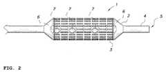
- FIG. 2is a top elevational view of the prewire channel stent 1 of FIG. 1 in which the balloon 2 is in a deflated status.
- the channel 6has the openings 7 disposed at one and another end and also along the middle of the channel 6 as shown in FIG. 2 , such that a guidewire can enter and leave the channel 6 at the openings 7.
- the channel 6is shown in dashed outline in FIG. 1 and in FIG. 2 , and is provided between the metallic mesh material 3 and the balloon 2.
- FIG. 3Ais a transverse cross-sectional view of the prewire channel stent 1 of FIG. 1 in which the balloon 2 is in the inflated status.
- the curved surface of the balloon 2is visible and bounds a lower side 61 of the channel 6.
- the metallic mesh material 3bounds an upper side 31 of the channel 6.
- the channel 6can be substantially closed, or alternatively can still remain open, when the metallic mesh material 3 is in the diastolic status and the balloon 2 is in the inflated status.
- the terms “upper” and “lower”are conveniently introduced for clarity of explanation, but in implementations the stent 1 can be located differently.
- FIG. 3Bis a partial transverse cross-sectional view of the prewire channel stent of FIG. 1 in which the balloon is in the inflated status, but wherein channel 6 has an additional wall 62.
- the prewire channel stent 1has the second passage (i.e., channel 6) implemented with wall 62 located between the metallic mesh material 3 and the balloon 2.
- the wall 62could exist not only in the inflated status but also in deflated status.
- FIG. 4is a longitudinal cross-sectional view of the prewire channel stent 1 of FIG. 1 , wherein the balloon 2 is in the inflated status.
- This viewshows a side view of the channel 6.
- the curved surface of the balloon 2is visible and bounds the lower side of the channel 6.
- the metallic mesh material 3bounds the upper side of the channel 6.
- the channel 6can exist or, alternatively can disappear (i.e. collapse) when the balloon 2 is in the inflated status. Openings 7 exist at both ends of the channel 6. More openings can exist between the both ends of the channel 6, as shown in the drawings.
- the channel 6can extend from the end of metallic mesh material to the another end of metallic mesh material.
- channelor “space”, as used herein, means that the passageway is formed by the element referred to as the "channel 6", and this passageway can be in the form of a channel formed in the adjacent materials or can be provided as a space between the adjacent materials.
- the width of the channel 6is selected to be sufficient for passage of the wire 30 therethrough in the manner explained above, and can be relatively thin and narrow or can be relative wide. All such variations are contemplated as being within the scope of the present invention.
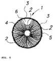
- FIG. 5is a transverse cross-sectional view of the prewire channel stent 1 of FIG. 2 in which the balloon 2 is in the deflated status.
- the parts shown in this vieware those described hereinabove.
- the folds of the balloon 2are visible.
- the upper boundaryis the metallic mesh material or - alternatively - also can be folded balloon, and lower boundary is the folded balloon.
- the channel 6is shown as being relatively large in this view for the sake of clarity, and is not limited to this specific size or shape shown.
- FIG. 6is a longitudinal cross-sectional view of the prewire channel stent 1 of FIG. 1 , wherein the balloon 2 is in the inflated status.
- This viewshows a side view of the channel 6 with guidewire 30 going through the channel 6 and the guidewire 20 passing through the lumen 5 of the catheter 4.
- the guidewire 30can go through any openings 7 of the channel 6.
- the channel 6can be substantially closed, or alternatively can still remain open, when the metallic mesh material 3 is in the diastolic status and the balloon 2 is in the inflated status.
- a guidewire 20is mentioned.
- the role of the guidewire 20is for tracking.
- the guidewire 20is firstly sent to the vessels which are to be treated.
- a balloon and stentare sent through the guidewire 20 (by tracking) to the desired position of the vessels.
- All known conventional stents and balloons currently designedhave a central channel (corresponding to channel 4 of the present invention) with a lumen for the guidewire 20 to go through.
- there is not any channel or space in currently designed stentsreferred to herein as "conventional stents" that correspond to the channel 6 of the present invention which is for another guidewire (i.e., a second guidewire, namely guidewire 30 shown in FIG. 6 ) between the metallic mesh material 3 and the balloon 2.
- Vessels in the human bodycan be described somewhat like highways in the country which have forks or branches (i.e., bifurcation). In a patient, therefore, if the narrow position is in bifurcation, it is necessary to use two guidewires in each of the branches. So when the stent is sent through the lumen 5 of its central channel 4 by one guidewire in a bifurcation position to release the stent in main branch, then another guidewire in the side branch must be between the metallic mesh material and the vessel wall (in other words, the wire is outside the stent).
- the guidewire outside the stent in the side branchshould be pulled back and then sent to the main branch again through the inside stent and the guidewire in original main branches should be pulled back and sent to side branch across the metallic mesh material through the inside stent (or the doctor can send another wire across the metallic mesh material to the side branch through inside the stent).
- This processis called "wire exchange” which is achieved in the vessels and therefore is complicated and time consuming and sometimes cannot be finished because of the complications that may arise.
- the channel 6is provided so that the guidewire in the side branch can go across the metallic mesh material through the inside of the stent outside the human body. Therefore, wire exchange is not necessary (i.e. this makes the step of wire exchange unnecessary).
- a typical conventional or known stentWhen an ostial lesion is treated, a typical conventional or known stent has to be deployed precisely at the desired location.
- some operators like to employ the Szabo techniquecf. Jain et al.: specifically, they inflate part of the balloon with low pressure, and then deflate the balloon to allow the guidewire to pass through the space between the metallic mesh material and the balloon.
- this procedurehas a risk of stent dislodgement (cf. Jain et al.).
- the channel 6is provided to avoid the risk of stent dislodgement.
- the lesions involved in the bifurcation of the vesselscould have different lengths.
- the principle of treating such lesionsis to use the stent to fully cover the lesions.
- the channel 6can be a different length from one end of the metallic mesh material 3 of the stent to the another end of metallic mesh material 3.
- the openings 7 of the channel 6can be provided in multiple locations provided along the channel 6. This design allows the guidewire 30 to go across any openings 7 of the channel 6 based on the need of the length of the lesion in the vessel.
- This stent systemcan be applied not only in vessels, but also in bronchi, bile ducts, urethrae, esophagi, and other organs or tissues.
- FIGS. 7A - 7EThe following illustrates a working example for a conventional stent, shown in FIGS. 7A - 7E , and a working example for the Pre-Wire Channel Stent of the present invention, shown in FIGS. 8A-8E .
- Step 1is shown in FIG. 7A , wherein a guidewire 20 is sent to a main branch and a guidewire 21 is sent to a side branch.
- Step 2is shown in FIG. 7B , wherein a system P1 of a conventional or known stent and balloon is sent through the guidewire 20 (by tracking) to the desired position of the vessels.
- Step 3is shown in FIG. 7C , a balloon P2 is inflated and a conventional stent P3 is dilated to support the vessel, and the guidewire 20 is still in the main branches through the lumen of the stent and the guidewire 21 is in the side branch through the space between the vessel wall and the metallic mesh material of the stent (i.e., outside the stent).
- Step 4is shown in FIG. 7D , wherein the balloon P2 is deflated and pulled out of the vessel.
- the guidewire 20is still in the main branches through the lumen of the stent and the guidewire 21 is in the side branch through the space between the vessel wall and the metallic mesh material of the stent (i.e., outside the stent).
- Step 5is shown in FIG. 7E , in which the guidewire 20 is pulled back and then sent in the lumen of the stent through the metallic mesh to the side branch.
- the guidewire 21is also pulled back and then sent through the lumen of the stent to main branch.
- the process of "wire exchange”is finished, as schematically indicated by the dashed lines in FIG. 7E .
- Step 1is shown in FIG. 8A , wherein the guidewire 20 is sent to the main branch and the guidewire 30 is sent to the side branch.
- Step 2is shown in FIG. 8B , wherein the prewire channel stent 1 with the guidewire 30 goes through the channel 6 while outside the human body and is then sent through the guidewire 20 (by tracking) to the desired position of the vessels.
- Step 3is shown in FIG. 8C , wherein the prewire channel stent 1 with the guidewire 30 goes through the channel 6 is sent by tracking guidewire 20 to the desired position of the vessel (at the bifurcation lesion).
- the balloon 2is in the deflated status in this view, and the metallic mesh material 3 is mounted in the balloon 2 and the guidewire 30 in the lumen of the catheter 4.
- Step 4is shown in FIG. 8D , wherein the balloon 2 is inflated and the metallic mesh material 3 is dilated.
- the guidewire 30 from the side branchis in the channel 6 and the guidewire 20 is disposed in the main branch.
- Step 5is shown in FIG. 8E , wherein the balloon 2 is deflated and withdrawn from the vessel. As seen in FIG. 8E , "wire exchange" is not necessary. This is in contrast to FIG. 7E of the prior device.
Landscapes
- Health & Medical Sciences (AREA)
- Engineering & Computer Science (AREA)
- Biomedical Technology (AREA)
- Cardiology (AREA)
- Oral & Maxillofacial Surgery (AREA)
- Transplantation (AREA)
- Heart & Thoracic Surgery (AREA)
- Vascular Medicine (AREA)
- Life Sciences & Earth Sciences (AREA)
- Animal Behavior & Ethology (AREA)
- General Health & Medical Sciences (AREA)
- Public Health (AREA)
- Veterinary Medicine (AREA)
- Media Introduction/Drainage Providing Device (AREA)
Abstract
Description
- The present invention relates generally to a medical device for the treatment of vascular disease.
- Cardiovascular stents are widely used in the treatment of vascular diseases. For example, stents have been broadly implanted in vessels to treat vessel narrowing, occlusion, aneurysm, and dissection, among other conditions. A typical conventional or known stent contains a metallic mesh material that is mounted or carried on a deflated balloon. In the centre of the balloon is a channel, through which a guidewire can pass to facilitate movement through the arteries; however, there is no channel between the metallic mesh material and the balloon. A guidewire is inserted to the vessel and pass the location that needs to be treated and then the cardiovascular stent mounted or carried on a deflated balloon is inserted into the vessel and delivered to the desired location through this guidewire to facilitate movement through the arteries. When the stent is at the desired location, the balloon is inflated to expand and, thereby, deploy the stent to support the artery.
- Vessels have branches; when narrowing, these narrowed branches are referred to as "bifurcation lesions". When treating a bifurcation lesion with a conventional or known stent, one guidewire is delivered to the main branch, and another guidewire is delivered to a side branch. These two wires have to be exchanged (which is called wire-exchange) during the operation. This procedure is complicated and time-consuming.
- In addition, when an ostial lesion (usually defined as a lesion within 3 mm of the ostium of the vessel at the aorto-ostial or branch-ostial junction) is treated, a typical conventional or known stent has to be deployed precisely at the desired location. To ensure precise deployment at the desired location, some operators like to employ the Szabo technique: specifically, they inflate part of the balloon with low pressure, and then deflate the balloon premounted by metallic mesh material to allow the guidewire to pass through the space between the metallic mesh material and the balloon for the precise deployment of the stent. However, this procedure has a risk of stent dislodgement. Details for the Szabo technique can be found in the following paper: "Jain RK, Padmanabhan TN, Chitnis N. Causes of failure with Szabo technique - an analysis of nine cases. Indian Heart J. 2013 May-Jun; 65(3):264-8. doi: 10.1016/j.ihj.2013.04.023. Epub 2013 Apr 10", referred to as "Jain et al."
US Patent No. 8,771,342 issued July 8, 2014 to Vardi is of interest for showing the background of this type of invention, and this reference is hereby incorporated herein in its entirety. In this reference, a method of deploying a stent in a bifurcation is shown that includes introducing two guidewires through the main vessel and using the two guidewires for guiding a dual lumen catheter carrying a stent first to an initial position proximal to the stent deployment position, retracting one wire, and projecting it from the catheter and through a side of the stent a branch guidewire into the second branch vessel, and then moving the catheter to the predetermined deployment position while guided by the main guidewire in the first branch vessel, and the branch guidewire in the second branch vessel. The stent is then expanded, and the catheter is removed with the stent remaining in its deployed position An alternative embodiment includes introducing one wire, advancing the system over the one wire and subsequently introducing the second wire.US Patent No. 7,771,462 issued August 10, 2010 to Davidson, et al. is of interest for showing the background of this type of invention, and this reference is hereby incorporated herein in its entirety. This reference describes a designed catheter system comprises a catheter having a catheter body with a distal end, a proximal end, a main vessel guidewire lumen for receiving a main vessel guidewire and a balloon disposing at the distal end of the catheter body. The catheter further includes a side member that is disposed adjacent to the catheter body. The side member has a distal end, a proximal end, and a branch vessel guidewire lumen for receiving a branch vessel guidewire. A stent having a side hole is disposed over the balloon, and a distal portion of the side member is disposed beneath at least a portion of the stent while being adjacent to and movable with respect to the balloon.US Patent No. 8,828,071 issued September 9, 2014 to Bourang et al is of interest for showing the background of this type of invention, and this reference is hereby incorporated herein in its entirety. This references discusses a system for treating a bifurcation that includes first and second delivery catheters, each having an expandable member. A stent having a side hole is disposed on the second delivery catheter. A portion of the first delivery catheter is disposed under a portion of the stent. The first delivery catheter is slidable relative to the second delivery catheter, and the first delivery catheter passes through the side hole. Expansion of the first expandable member expands a proximal portion of the stent in a main branch vessel, and expansion of the second expandable member expands a distal portion of the stent in a side branch vessel.US Patent No. 8,808,347 issued August 19, 2014 to Bourang et al is of interest for showing alignment of the side branch stent with the main branch stent, and this reference is hereby incorporated herein in its entirety. This reference describes a system for treating a bifurcation includes a first radially expandable stent and a second radially expandable stent. The first stent has a side hole and a plurality of lateral elements extending from the side hole. The second stent has a plurality of axial elements extending away from the proximal end of the second stent. The axial elements of the second stent interdigitate with the lateral elements of the first stent when both stents have been expanded.US Patent No. 8,795,347 issued August 5, 2014 to Bourang et al is of interest for showing methods and systems for treating a bifurcation with provisional side branch stenting.- There is a need for a newly designed stent to overcome the shortcomings of the typical conventional or known stent.
- From the foregoing, it is seen that it is a problem in the art to provide a device meeting the above requirements. According to the present invention, a device is provided which meets the aforementioned requirements and needs in the prior art. Specifically, the device according to the present invention provides a prewire channel stent having a structure that includes a balloon having a metallic mesh material outside the balloon, a central passage with ancillary components that inflate or deflate the balloon, and a second passage disposed between the metallic mesh material and the balloon.
- Other objects and advantages of the present invention will be more readily apparent from the following detailed description when read in conjunction with the accompanying drawings.
FIG. 1 is a top elevational view of a prewire channel stent in which a balloon is in an inflated status.FIG. 2 is a top elevational view of the prewire channel stent ofFIG. 1 in which the balloon is in a deflated status.FIG. 3A is a transverse cross-sectional view of the prewire channel stent ofFIG. 1 in which the balloon is in the inflated status.FIG. 3B is a partial transverse cross-sectional view of the prewire channel stent ofFIG. 1 in which the balloon is in the inflated status, but wherein the channel has an additional wall.FIG. 4 is a longitudinal cross-sectional view of the prewire channel stent ofFIG. 1 , wherein the balloon is in the inflated status.FIG. 5 is a transverse cross-sectional view of the prewire channel stent ofFIG. 2 in which the balloon is in the deflated status.FIG.6 is a a longitudinal cross-sectional view of the prewire channel stent ofFIG. 1 , wherein the balloon is in the inflated status and a guidewire is in a lumen of a catheter, and another guidewire is in the channel or space.FIG. 1 is a top elevational view of aprewire channel stent 1 having anexpandable balloon 2, and in which theexpandable balloon 2 is in an inflated status. Thisexpandable balloon 2 is in the inflated status during deployment, and is in a deflated status before deployment. Ametallic mesh material 3 is premounted or carried on theexpandable balloon 2.- The
metallic mesh material 3 is expanded when theballoon 2 is inflated during deployment, but is in a systolical status when theballoon 2 is deflated (i.e. is in its deflated status) before deployment (FIG. 2 ). Acentral catheter 4 goes through theballoon 2, and has alumen 5 which allows a tracking guidewire 20 (shown inFIG. 6 ) to go therethrough. - A
channel 6 is shown in dashed outline inFIG. 1 andFIG. 2 , and is provided between themetallic mesh material 3 and theexpandable balloon 2. Channel 6 can also be regarded as a space (betweenmetallic mesh material 3 and expandable balloon 2). Although a "channel" can be considered to have a wall as boundary, a wall is not required. An embodiment with a dedicated wall will be explained in connection withFIG. 3B . - A plurality of openings 7 (shown in
FIGS. 1 ,2 ,4 , and6 ) are provided for communication between thechannel 6 and a region outside themetallic mesh material 3. Theopenings 7 are formed through themetallic mesh material 3 as shown inFIG. 6 . Theopenings 7 are provided so that achannel guidewire 30 can pass into thechannel 6 and then exit through one of theopenings 7, as shown inFIG. 6 . - Alternative or additional embodiments are contemplated as being within the scope of the present invention. In one such embodiment, the
channel 6 can have a lining, for example a tubular lining which could be folded balloon or other material, through which thewire 30 can pass. In this embodiment, the lining would include openings that correspond to theopenings 7. In another such embodiment, thechannel 6 can be limited in extent such that is passes only partway along the length of themetallic mesh material 3; in a further variation on this embodiment, it is contemplated thatfewer openings 7 could be provided than the number shown, so that - for example - only a singlesuch opening 7 is provided. Also, the number ofopenings 7 is not limited to the number shown and illustrated; more or fewersuch openings 7 could be provided, within the scope of the present invention. - In use, one or
more guidewires 30 can go through one of theopenings 7 and into thechannel 6 when themetallic mesh material 3 is in the systole status and theballoon 2 is in the deflated status. Thechannel 6 can be substantially closed or - alternatively - can remain open until such time as themetallic mesh material 3 is in the diastolic status and theballoon 2 is in the inflated status. - As seen in
FIG. 1 , theballoon 2 extends longitudinally along thecentral catheter 4. Themetallic mesh material 3 shown inFIG. 1 surrounds the central region of theballoon 2. Thechannel 6 has theopenings 7 disposed as shown, such that theguidewire 30 can enter and leave thechannel 6 through any two of theseopenings 7.FIG. 6 illustrates this. FIG. 2 is a top elevational view of theprewire channel stent 1 ofFIG. 1 in which theballoon 2 is in a deflated status. Thechannel 6 has theopenings 7 disposed at one and another end and also along the middle of thechannel 6 as shown inFIG. 2 , such that a guidewire can enter and leave thechannel 6 at theopenings 7. Thechannel 6 is shown in dashed outline inFIG. 1 and inFIG. 2 , and is provided between themetallic mesh material 3 and theballoon 2.FIG. 3A is a transverse cross-sectional view of theprewire channel stent 1 ofFIG. 1 in which theballoon 2 is in the inflated status. The curved surface of theballoon 2 is visible and bounds alower side 61 of thechannel 6. Themetallic mesh material 3 bounds anupper side 31 of thechannel 6. Thechannel 6 can be substantially closed, or alternatively can still remain open, when themetallic mesh material 3 is in the diastolic status and theballoon 2 is in the inflated status. The terms "upper" and "lower" are conveniently introduced for clarity of explanation, but in implementations thestent 1 can be located differently.FIG. 3B is a partial transverse cross-sectional view of the prewire channel stent ofFIG. 1 in which the balloon is in the inflated status, but whereinchannel 6 has anadditional wall 62. In other words, theprewire channel stent 1 has the second passage (i.e., channel 6) implemented withwall 62 located between themetallic mesh material 3 and theballoon 2. Thewall 62 could exist not only in the inflated status but also in deflated status.FIG. 4 is a longitudinal cross-sectional view of theprewire channel stent 1 ofFIG. 1 , wherein theballoon 2 is in the inflated status. This view shows a side view of thechannel 6. In this view, the curved surface of theballoon 2 is visible and bounds the lower side of thechannel 6. Also as shown in this view, themetallic mesh material 3 bounds the upper side of thechannel 6. Thechannel 6 can exist or, alternatively can disappear (i.e. collapse) when theballoon 2 is in the inflated status.Openings 7 exist at both ends of thechannel 6. More openings can exist between the both ends of thechannel 6, as shown in the drawings. Thechannel 6 can extend from the end of metallic mesh material to the another end of metallic mesh material.- The terminology "channel" or "space", as used herein, means that the passageway is formed by the element referred to as the "
channel 6", and this passageway can be in the form of a channel formed in the adjacent materials or can be provided as a space between the adjacent materials. The width of thechannel 6 is selected to be sufficient for passage of thewire 30 therethrough in the manner explained above, and can be relatively thin and narrow or can be relative wide. All such variations are contemplated as being within the scope of the present invention. FIG. 5 is a transverse cross-sectional view of theprewire channel stent 1 ofFIG. 2 in which theballoon 2 is in the deflated status. The parts shown in this view are those described hereinabove. In this view, the folds of theballoon 2 are visible. The upper boundary is the metallic mesh material or - alternatively - also can be folded balloon, and lower boundary is the folded balloon. Thechannel 6 is shown as being relatively large in this view for the sake of clarity, and is not limited to this specific size or shape shown.FIG. 6 is a longitudinal cross-sectional view of theprewire channel stent 1 ofFIG. 1 , wherein theballoon 2 is in the inflated status. This view shows a side view of thechannel 6 withguidewire 30 going through thechannel 6 and theguidewire 20 passing through thelumen 5 of thecatheter 4. Theguidewire 30 can go through anyopenings 7 of thechannel 6. Thechannel 6 can be substantially closed, or alternatively can still remain open, when themetallic mesh material 3 is in the diastolic status and theballoon 2 is in the inflated status.- In the above discussion, a
guidewire 20 is mentioned. The role of theguidewire 20 is for tracking. When treating the patients, theguidewire 20 is firstly sent to the vessels which are to be treated. Thereafter, a balloon and stent are sent through the guidewire 20 (by tracking) to the desired position of the vessels. All known conventional stents and balloons currently designed have a central channel (corresponding to channel 4 of the present invention) with a lumen for theguidewire 20 to go through. However, there is not any channel or space in currently designed stents (referred to herein as "conventional stents") that correspond to thechannel 6 of the present invention which is for another guidewire (i.e., a second guidewire, namely guidewire 30 shown inFIG. 6 ) between themetallic mesh material 3 and theballoon 2. - Vessels in the human body can be described somewhat like highways in the country which have forks or branches (i.e., bifurcation). In a patient, therefore, if the narrow position is in bifurcation, it is necessary to use two guidewires in each of the branches. So when the stent is sent through the
lumen 5 of itscentral channel 4 by one guidewire in a bifurcation position to release the stent in main branch, then another guidewire in the side branch must be between the metallic mesh material and the vessel wall (in other words, the wire is outside the stent). The guidewire outside the stent in the side branch should be pulled back and then sent to the main branch again through the inside stent and the guidewire in original main branches should be pulled back and sent to side branch across the metallic mesh material through the inside stent (or the doctor can send another wire across the metallic mesh material to the side branch through inside the stent). This process is called "wire exchange" which is achieved in the vessels and therefore is complicated and time consuming and sometimes cannot be finished because of the complications that may arise. In the present invention, thechannel 6 is provided so that the guidewire in the side branch can go across the metallic mesh material through the inside of the stent outside the human body. Therefore, wire exchange is not necessary (i.e. this makes the step of wire exchange unnecessary). - When an ostial lesion is treated, a typical conventional or known stent has to be deployed precisely at the desired location. To ensure precise deployment at the desired location, some operators like to employ the Szabo technique (cf. Jain et al.): specifically, they inflate part of the balloon with low pressure, and then deflate the balloon to allow the guidewire to pass through the space between the metallic mesh material and the balloon. However, this procedure has a risk of stent dislodgement (cf. Jain et al.). In the present invention, the
channel 6 is provided to avoid the risk of stent dislodgement. - The lesions involved in the bifurcation of the vessels could have different lengths. The principle of treating such lesions is to use the stent to fully cover the lesions. The
channel 6 can be a different length from one end of themetallic mesh material 3 of the stent to the another end ofmetallic mesh material 3. Theopenings 7 of thechannel 6 can be provided in multiple locations provided along thechannel 6. This design allows theguidewire 30 to go across anyopenings 7 of thechannel 6 based on the need of the length of the lesion in the vessel. - This stent system can be applied not only in vessels, but also in bronchi, bile ducts, urethrae, esophagi, and other organs or tissues.
- The following illustrates a working example for a conventional stent, shown in
FIGS. 7A - 7E , and a working example for the Pre-Wire Channel Stent of the present invention, shown inFIGS. 8A-8E . - The procedures of a conventional or known stent implant for bifurcation lesion in a vessel as explained as follows.
Step 1 is shown inFIG. 7A , wherein aguidewire 20 is sent to a main branch and aguidewire 21 is sent to a side branch. Step 2 is shown inFIG. 7B , wherein a system P1 of a conventional or known stent and balloon is sent through the guidewire 20 (by tracking) to the desired position of the vessels.Step 3 is shown inFIG. 7C , a balloon P2 is inflated and a conventional stent P3 is dilated to support the vessel, and theguidewire 20 is still in the main branches through the lumen of the stent and theguidewire 21 is in the side branch through the space between the vessel wall and the metallic mesh material of the stent (i.e., outside the stent).Step 4 is shown inFIG. 7D , wherein the balloon P2 is deflated and pulled out of the vessel. Theguidewire 20 is still in the main branches through the lumen of the stent and theguidewire 21 is in the side branch through the space between the vessel wall and the metallic mesh material of the stent (i.e., outside the stent).Step 5 is shown inFIG. 7E , in which theguidewire 20 is pulled back and then sent in the lumen of the stent through the metallic mesh to the side branch. Theguidewire 21 is also pulled back and then sent through the lumen of the stent to main branch. The process of "wire exchange" is finished, as schematically indicated by the dashed lines inFIG. 7E .- The following illustrates the procedures for use of the prewire
channel stent implant 1 of the present invention for a bifurcation lesion in a vessel.Step 1 is shown inFIG. 8A , wherein theguidewire 20 is sent to the main branch and theguidewire 30 is sent to the side branch. Step 2 is shown inFIG. 8B , wherein theprewire channel stent 1 with theguidewire 30 goes through thechannel 6 while outside the human body and is then sent through the guidewire 20 (by tracking) to the desired position of the vessels.Step 3 is shown inFIG. 8C , wherein theprewire channel stent 1 with theguidewire 30 goes through thechannel 6 is sent by trackingguidewire 20 to the desired position of the vessel (at the bifurcation lesion). Theballoon 2 is in the deflated status in this view, and themetallic mesh material 3 is mounted in theballoon 2 and theguidewire 30 in the lumen of thecatheter 4.Step 4 is shown inFIG. 8D , wherein theballoon 2 is inflated and themetallic mesh material 3 is dilated. The guidewire 30 from the side branch is in thechannel 6 and theguidewire 20 is disposed in the main branch.Step 5 is shown inFIG. 8E , wherein theballoon 2 is deflated and withdrawn from the vessel. As seen inFIG. 8E , "wire exchange" is not necessary. This is in contrast toFIG. 7E of the prior device.- 2
- balloon
- 3
- mesh material
- 4
- central catheter / first passage
- 6
- channel / second passage
- 7
- opennings
- 20
- guidewire
- 21
- guidewire
- 30
- guidewire
- 31
- upper side
- 61
- lower side
Claims (6)
- A prewire channel stent (1), comprising:a central catheter (4) with a lumen (5);a balloon (2) disposed outside said central catheter (4), the balloon being inflatable and deflatable;a metallic mesh material (3) disposed outside said balloon (2) and surrounding said balloon (2);said central catheter (4) disposed within said balloon (2) having the lumen (5) as a central passage therethrough; and a second passage (6) disposed between said metallic mesh material (3) and said balloon (2), said second passage (6) being adapted to receive a guidewire (30).
- The prewire channel stent (1) according to claim 1, wherein said balloon (2) is an expandable balloon having an inflated status during deployment, and having a deflated status before deployment.
- The prewire channel stent (1) according to claim 1, wherein the second passage (6) has a different length extending from the end of the metallic mesh material (3) to the another end of the metallic mesh material (3).
- The prewire channel stent (1) according to claim 1, wherein a plurality of openings (7) are provided through the metallic mesh material (3) through which the guidewire (30) can pass, so that a portion of the guidewire (30) can exist in the second passage (6) .
- The prewire channel stent (1) according to claim 2, having a plurality of passages.
- The prewire channel stent (1) according to any of the preceding claims, wherein the second passage (6) has a wall located between the metallic mesh material (3) and the balloon (2).
Applications Claiming Priority (1)
| Application Number | Priority Date | Filing Date | Title |
|---|---|---|---|
| CN201320895986.4UCN203829102U (en) | 2013-10-09 | 2013-12-29 | Support for preformed guide-wire channel |
Publications (2)
| Publication Number | Publication Date |
|---|---|
| EP2889021A1true EP2889021A1 (en) | 2015-07-01 |
| EP2889021B1 EP2889021B1 (en) | 2017-12-13 |
Family
ID=52021085
Family Applications (1)
| Application Number | Title | Priority Date | Filing Date |
|---|---|---|---|
| EP14197293.5AActiveEP2889021B1 (en) | 2013-12-29 | 2014-12-11 | Prewire channel stent |
Country Status (1)
| Country | Link |
|---|---|
| EP (1) | EP2889021B1 (en) |
Cited By (1)
| Publication number | Priority date | Publication date | Assignee | Title |
|---|---|---|---|---|
| WO2018229801A1 (en)* | 2017-06-15 | 2018-12-20 | Ranjan Alok | An improved coronary stent delivery system for bifurcation lesions |
Citations (10)
| Publication number | Priority date | Publication date | Assignee | Title |
|---|---|---|---|---|
| DE29708803U1 (en)* | 1997-05-17 | 1997-07-31 | Jomed Implantate GmbH, 72414 Rangendingen | Radially expandable stent for implantation in a body vessel in the area of a vascular branch |
| EP0897700A1 (en)* | 1997-08-13 | 1999-02-24 | Advanced Cardiovascular Systems, Inc. | Stent and catheter assembly and method for treating bifurcations |
| US6007517A (en)* | 1996-08-19 | 1999-12-28 | Anderson; R. David | Rapid exchange/perfusion angioplasty catheter |
| US20040143286A1 (en)* | 2003-01-17 | 2004-07-22 | Johnson Eric G. | Catheter with disruptable guidewire channel |
| US7771462B1 (en) | 1999-06-04 | 2010-08-10 | Boston Scientific Scimed, Inc. | Catheter with side sheath and methods |
| US20120089220A1 (en)* | 2000-02-18 | 2012-04-12 | E.V.R. Endovascular Researches S.A. | Microcatheter |
| US8771342B2 (en) | 1996-11-04 | 2014-07-08 | Boston Scientific Scimed, Inc. | Methods for deploying stents in bifurcations |
| US8795347B2 (en) | 2008-09-25 | 2014-08-05 | Advanced Bifurcation Systems, Inc. | Methods and systems for treating a bifurcation with provisional side branch stenting |
| US8808347B2 (en) | 2008-09-25 | 2014-08-19 | Advanced Bifurcation Systems, Inc. | Stent alignment during treatment of a bifurcation |
| US8828071B2 (en) | 2008-09-25 | 2014-09-09 | Advanced Bifurcation Systems, Inc. | Methods and systems for ostial stenting of a bifurcation |
- 2014
- 2014-12-11EPEP14197293.5Apatent/EP2889021B1/enactiveActive
Patent Citations (10)
| Publication number | Priority date | Publication date | Assignee | Title |
|---|---|---|---|---|
| US6007517A (en)* | 1996-08-19 | 1999-12-28 | Anderson; R. David | Rapid exchange/perfusion angioplasty catheter |
| US8771342B2 (en) | 1996-11-04 | 2014-07-08 | Boston Scientific Scimed, Inc. | Methods for deploying stents in bifurcations |
| DE29708803U1 (en)* | 1997-05-17 | 1997-07-31 | Jomed Implantate GmbH, 72414 Rangendingen | Radially expandable stent for implantation in a body vessel in the area of a vascular branch |
| EP0897700A1 (en)* | 1997-08-13 | 1999-02-24 | Advanced Cardiovascular Systems, Inc. | Stent and catheter assembly and method for treating bifurcations |
| US7771462B1 (en) | 1999-06-04 | 2010-08-10 | Boston Scientific Scimed, Inc. | Catheter with side sheath and methods |
| US20120089220A1 (en)* | 2000-02-18 | 2012-04-12 | E.V.R. Endovascular Researches S.A. | Microcatheter |
| US20040143286A1 (en)* | 2003-01-17 | 2004-07-22 | Johnson Eric G. | Catheter with disruptable guidewire channel |
| US8795347B2 (en) | 2008-09-25 | 2014-08-05 | Advanced Bifurcation Systems, Inc. | Methods and systems for treating a bifurcation with provisional side branch stenting |
| US8808347B2 (en) | 2008-09-25 | 2014-08-19 | Advanced Bifurcation Systems, Inc. | Stent alignment during treatment of a bifurcation |
| US8828071B2 (en) | 2008-09-25 | 2014-09-09 | Advanced Bifurcation Systems, Inc. | Methods and systems for ostial stenting of a bifurcation |
Non-Patent Citations (1)
| Title |
|---|
| JAIN RK; PADMANABHAN TN; CHITNIS N.: "Causes of failure with Szabo technique - an analysis of nine cases", INDIAN HEART J., vol. 65, no. 3, May 2013 (2013-05-01), pages 264 - 8 |
Cited By (1)
| Publication number | Priority date | Publication date | Assignee | Title |
|---|---|---|---|---|
| WO2018229801A1 (en)* | 2017-06-15 | 2018-12-20 | Ranjan Alok | An improved coronary stent delivery system for bifurcation lesions |
Also Published As
| Publication number | Publication date |
|---|---|
| EP2889021B1 (en) | 2017-12-13 |
Similar Documents
| Publication | Publication Date | Title |
|---|---|---|
| CA2246995C (en) | Endolumenal prosthesis and method of use in bifurcation regions of body lumens | |
| EP1587449B1 (en) | Varying-diameter vascular implant and balloon | |
| EP1894545B1 (en) | Multiple in vivo implant delivery device | |
| EP3031425B1 (en) | Introducer for an iliac side branch device | |
| US6027519A (en) | Catheter with expandable multiband segment | |
| EP2328522B1 (en) | Directional expansion of intraluminal devices | |
| EP2777649B1 (en) | Delivery system for expandable stents | |
| JP5070215B2 (en) | Bifurcated catheter assembly | |
| US20070270935A1 (en) | Dual balloon catheter and deployment of same | |
| US20100298922A1 (en) | Angioplasty Assembly | |
| KR20080067953A (en) | Deliverable stent in the vascular system to strengthen vascular abnormalities | |
| JP2007500577A (en) | Stent deployment system and method | |
| CN104023672B (en) | Method and device for endovascular treatment of aortic disease | |
| CN112804964B (en) | Stent-type aortic implant and assembly formed by two such implants | |
| US20130345796A1 (en) | Apparatus and method for aortic protection and tavi planar alignment | |
| US9468548B2 (en) | Systems and methods for delivering a stent to a body lumen | |
| US9387102B2 (en) | Sheathless predilatation angioplasty and stent deployment catheter | |
| US20110054438A1 (en) | Stent delivery at a bifurcation, systems and methods | |
| US10123893B2 (en) | Prewire channel stent | |
| JP2010528802A (en) | Bifurcated balloon & stent delivery system | |
| EP2889021B1 (en) | Prewire channel stent | |
| US20240139007A1 (en) | Integrated deployment system (delivery mechanism) for intracranial atherosclerosis stent | |
| EP3858298B1 (en) | Bifurcated balloon expandable stent assembly | |
| CN113967114B (en) | Quick aortic repair stent, stent kit and delivery system | |
| EP2781204A1 (en) | Intravascular system for introducing and fastening an autogenous vascular prosthesis |
Legal Events
| Date | Code | Title | Description |
|---|---|---|---|
| PUAI | Public reference made under article 153(3) epc to a published international application that has entered the european phase | Free format text:ORIGINAL CODE: 0009012 | |
| 17P | Request for examination filed | Effective date:20141211 | |
| AK | Designated contracting states | Kind code of ref document:A1 Designated state(s):AL AT BE BG CH CY CZ DE DK EE ES FI FR GB GR HR HU IE IS IT LI LT LU LV MC MK MT NL NO PL PT RO RS SE SI SK SM TR | |
| AX | Request for extension of the european patent | Extension state:BA ME | |
| R17P | Request for examination filed (corrected) | Effective date:20150817 | |
| RBV | Designated contracting states (corrected) | Designated state(s):AL AT BE BG CH CY CZ DE DK EE ES FI FR GB GR HR HU IE IS IT LI LT LU LV MC MK MT NL NO PL PT RO RS SE SI SK SM TR | |
| 17Q | First examination report despatched | Effective date:20151113 | |
| GRAP | Despatch of communication of intention to grant a patent | Free format text:ORIGINAL CODE: EPIDOSNIGR1 | |
| GRAS | Grant fee paid | Free format text:ORIGINAL CODE: EPIDOSNIGR3 | |
| GRAA | (expected) grant | Free format text:ORIGINAL CODE: 0009210 | |
| INTG | Intention to grant announced | Effective date:20171018 | |
| REG | Reference to a national code | Ref country code:GB Ref legal event code:FG4D | |
| REG | Reference to a national code | Ref country code:AT Ref legal event code:REF Ref document number:953662 Country of ref document:AT Kind code of ref document:T Effective date:20171215 Ref country code:CH Ref legal event code:EP | |
| REG | Reference to a national code | Ref country code:IE Ref legal event code:FG4D | |
| REG | Reference to a national code | Ref country code:DE Ref legal event code:R096 Ref document number:602014018420 Country of ref document:DE | |
| REG | Reference to a national code | Ref country code:NL Ref legal event code:MP Effective date:20171213 | |
| PG25 | Lapsed in a contracting state [announced via postgrant information from national office to epo] | Ref country code:FI Free format text:LAPSE BECAUSE OF FAILURE TO SUBMIT A TRANSLATION OF THE DESCRIPTION OR TO PAY THE FEE WITHIN THE PRESCRIBED TIME-LIMIT Effective date:20171213 Ref country code:NO Free format text:LAPSE BECAUSE OF FAILURE TO SUBMIT A TRANSLATION OF THE DESCRIPTION OR TO PAY THE FEE WITHIN THE PRESCRIBED TIME-LIMIT Effective date:20180313 Ref country code:SE Free format text:LAPSE BECAUSE OF FAILURE TO SUBMIT A TRANSLATION OF THE DESCRIPTION OR TO PAY THE FEE WITHIN THE PRESCRIBED TIME-LIMIT Effective date:20171213 | |
| REG | Reference to a national code | Ref country code:AT Ref legal event code:MK05 Ref document number:953662 Country of ref document:AT Kind code of ref document:T Effective date:20171213 | |
| PG25 | Lapsed in a contracting state [announced via postgrant information from national office to epo] | Ref country code:BG Free format text:LAPSE BECAUSE OF FAILURE TO SUBMIT A TRANSLATION OF THE DESCRIPTION OR TO PAY THE FEE WITHIN THE PRESCRIBED TIME-LIMIT Effective date:20180313 Ref country code:LV Free format text:LAPSE BECAUSE OF FAILURE TO SUBMIT A TRANSLATION OF THE DESCRIPTION OR TO PAY THE FEE WITHIN THE PRESCRIBED TIME-LIMIT Effective date:20171213 Ref country code:HR Free format text:LAPSE BECAUSE OF FAILURE TO SUBMIT A TRANSLATION OF THE DESCRIPTION OR TO PAY THE FEE WITHIN THE PRESCRIBED TIME-LIMIT Effective date:20171213 Ref country code:GR Free format text:LAPSE BECAUSE OF FAILURE TO SUBMIT A TRANSLATION OF THE DESCRIPTION OR TO PAY THE FEE WITHIN THE PRESCRIBED TIME-LIMIT Effective date:20180314 Ref country code:RS Free format text:LAPSE BECAUSE OF FAILURE TO SUBMIT A TRANSLATION OF THE DESCRIPTION OR TO PAY THE FEE WITHIN THE PRESCRIBED TIME-LIMIT Effective date:20171213 | |
| PG25 | Lapsed in a contracting state [announced via postgrant information from national office to epo] | Ref country code:NL Free format text:LAPSE BECAUSE OF FAILURE TO SUBMIT A TRANSLATION OF THE DESCRIPTION OR TO PAY THE FEE WITHIN THE PRESCRIBED TIME-LIMIT Effective date:20171213 | |
| PG25 | Lapsed in a contracting state [announced via postgrant information from national office to epo] | Ref country code:EE Free format text:LAPSE BECAUSE OF FAILURE TO SUBMIT A TRANSLATION OF THE DESCRIPTION OR TO PAY THE FEE WITHIN THE PRESCRIBED TIME-LIMIT Effective date:20171213 Ref country code:SK Free format text:LAPSE BECAUSE OF FAILURE TO SUBMIT A TRANSLATION OF THE DESCRIPTION OR TO PAY THE FEE WITHIN THE PRESCRIBED TIME-LIMIT Effective date:20171213 Ref country code:CY Free format text:LAPSE BECAUSE OF FAILURE TO SUBMIT A TRANSLATION OF THE DESCRIPTION OR TO PAY THE FEE WITHIN THE PRESCRIBED TIME-LIMIT Effective date:20171213 Ref country code:CZ Free format text:LAPSE BECAUSE OF FAILURE TO SUBMIT A TRANSLATION OF THE DESCRIPTION OR TO PAY THE FEE WITHIN THE PRESCRIBED TIME-LIMIT Effective date:20171213 Ref country code:ES Free format text:LAPSE BECAUSE OF FAILURE TO SUBMIT A TRANSLATION OF THE DESCRIPTION OR TO PAY THE FEE WITHIN THE PRESCRIBED TIME-LIMIT Effective date:20171213 | |
| PG25 | Lapsed in a contracting state [announced via postgrant information from national office to epo] | Ref country code:PL Free format text:LAPSE BECAUSE OF FAILURE TO SUBMIT A TRANSLATION OF THE DESCRIPTION OR TO PAY THE FEE WITHIN THE PRESCRIBED TIME-LIMIT Effective date:20171213 Ref country code:SM Free format text:LAPSE BECAUSE OF FAILURE TO SUBMIT A TRANSLATION OF THE DESCRIPTION OR TO PAY THE FEE WITHIN THE PRESCRIBED TIME-LIMIT Effective date:20171213 Ref country code:AT Free format text:LAPSE BECAUSE OF FAILURE TO SUBMIT A TRANSLATION OF THE DESCRIPTION OR TO PAY THE FEE WITHIN THE PRESCRIBED TIME-LIMIT Effective date:20171213 Ref country code:IT Free format text:LAPSE BECAUSE OF FAILURE TO SUBMIT A TRANSLATION OF THE DESCRIPTION OR TO PAY THE FEE WITHIN THE PRESCRIBED TIME-LIMIT Effective date:20171213 Ref country code:IS Free format text:LAPSE BECAUSE OF FAILURE TO SUBMIT A TRANSLATION OF THE DESCRIPTION OR TO PAY THE FEE WITHIN THE PRESCRIBED TIME-LIMIT Effective date:20180413 Ref country code:RO Free format text:LAPSE BECAUSE OF FAILURE TO SUBMIT A TRANSLATION OF THE DESCRIPTION OR TO PAY THE FEE WITHIN THE PRESCRIBED TIME-LIMIT Effective date:20171213 | |
| REG | Reference to a national code | Ref country code:DE Ref legal event code:R097 Ref document number:602014018420 Country of ref document:DE | |
| PLBE | No opposition filed within time limit | Free format text:ORIGINAL CODE: 0009261 | |
| STAA | Information on the status of an ep patent application or granted ep patent | Free format text:STATUS: NO OPPOSITION FILED WITHIN TIME LIMIT | |
| 26N | No opposition filed | Effective date:20180914 | |
| PG25 | Lapsed in a contracting state [announced via postgrant information from national office to epo] | Ref country code:DK Free format text:LAPSE BECAUSE OF FAILURE TO SUBMIT A TRANSLATION OF THE DESCRIPTION OR TO PAY THE FEE WITHIN THE PRESCRIBED TIME-LIMIT Effective date:20171213 | |
| PG25 | Lapsed in a contracting state [announced via postgrant information from national office to epo] | Ref country code:SI Free format text:LAPSE BECAUSE OF FAILURE TO SUBMIT A TRANSLATION OF THE DESCRIPTION OR TO PAY THE FEE WITHIN THE PRESCRIBED TIME-LIMIT Effective date:20171213 | |
| PG25 | Lapsed in a contracting state [announced via postgrant information from national office to epo] | Ref country code:LU Free format text:LAPSE BECAUSE OF NON-PAYMENT OF DUE FEES Effective date:20181211 Ref country code:MC Free format text:LAPSE BECAUSE OF FAILURE TO SUBMIT A TRANSLATION OF THE DESCRIPTION OR TO PAY THE FEE WITHIN THE PRESCRIBED TIME-LIMIT Effective date:20171213 | |
| REG | Reference to a national code | Ref country code:BE Ref legal event code:MM Effective date:20181231 | |
| PG25 | Lapsed in a contracting state [announced via postgrant information from national office to epo] | Ref country code:BE Free format text:LAPSE BECAUSE OF NON-PAYMENT OF DUE FEES Effective date:20181231 | |
| PG25 | Lapsed in a contracting state [announced via postgrant information from national office to epo] | Ref country code:MT Free format text:LAPSE BECAUSE OF NON-PAYMENT OF DUE FEES Effective date:20181211 | |
| PG25 | Lapsed in a contracting state [announced via postgrant information from national office to epo] | Ref country code:TR Free format text:LAPSE BECAUSE OF FAILURE TO SUBMIT A TRANSLATION OF THE DESCRIPTION OR TO PAY THE FEE WITHIN THE PRESCRIBED TIME-LIMIT Effective date:20171213 | |
| PG25 | Lapsed in a contracting state [announced via postgrant information from national office to epo] | Ref country code:PT Free format text:LAPSE BECAUSE OF FAILURE TO SUBMIT A TRANSLATION OF THE DESCRIPTION OR TO PAY THE FEE WITHIN THE PRESCRIBED TIME-LIMIT Effective date:20171213 | |
| PG25 | Lapsed in a contracting state [announced via postgrant information from national office to epo] | Ref country code:LT Free format text:LAPSE BECAUSE OF FAILURE TO SUBMIT A TRANSLATION OF THE DESCRIPTION OR TO PAY THE FEE WITHIN THE PRESCRIBED TIME-LIMIT Effective date:20171213 Ref country code:HU Free format text:LAPSE BECAUSE OF FAILURE TO SUBMIT A TRANSLATION OF THE DESCRIPTION OR TO PAY THE FEE WITHIN THE PRESCRIBED TIME-LIMIT; INVALID AB INITIO Effective date:20141211 Ref country code:MK Free format text:LAPSE BECAUSE OF NON-PAYMENT OF DUE FEES Effective date:20171213 | |
| PG25 | Lapsed in a contracting state [announced via postgrant information from national office to epo] | Ref country code:AL Free format text:LAPSE BECAUSE OF FAILURE TO SUBMIT A TRANSLATION OF THE DESCRIPTION OR TO PAY THE FEE WITHIN THE PRESCRIBED TIME-LIMIT Effective date:20171213 | |
| PGFP | Annual fee paid to national office [announced via postgrant information from national office to epo] | Ref country code:IE Payment date:20221219 Year of fee payment:9 | |
| P01 | Opt-out of the competence of the unified patent court (upc) registered | Effective date:20230613 | |
| PGFP | Annual fee paid to national office [announced via postgrant information from national office to epo] | Ref country code:GB Payment date:20231220 Year of fee payment:10 | |
| PGFP | Annual fee paid to national office [announced via postgrant information from national office to epo] | Ref country code:FR Payment date:20231220 Year of fee payment:10 Ref country code:DE Payment date:20231214 Year of fee payment:10 | |
| PGFP | Annual fee paid to national office [announced via postgrant information from national office to epo] | Ref country code:CH Payment date:20240110 Year of fee payment:10 | |
| REG | Reference to a national code | Ref country code:IE Ref legal event code:MM4A | |
| PG25 | Lapsed in a contracting state [announced via postgrant information from national office to epo] | Ref country code:IE Free format text:LAPSE BECAUSE OF NON-PAYMENT OF DUE FEES Effective date:20231211 | |
| PG25 | Lapsed in a contracting state [announced via postgrant information from national office to epo] | Ref country code:IE Free format text:LAPSE BECAUSE OF NON-PAYMENT OF DUE FEES Effective date:20231211 | |
| REG | Reference to a national code | Ref country code:DE Ref legal event code:R119 Ref document number:602014018420 Country of ref document:DE | |
| REG | Reference to a national code | Ref country code:CH Ref legal event code:PL | |
| GBPC | Gb: european patent ceased through non-payment of renewal fee | Effective date:20241211 |