EP2887315B1 - Camera calibration device, method for implementing calibration, program and camera for movable body - Google Patents
Camera calibration device, method for implementing calibration, program and camera for movable bodyDownload PDFInfo
- Publication number
- EP2887315B1 EP2887315B1EP14196761.2AEP14196761AEP2887315B1EP 2887315 B1EP2887315 B1EP 2887315B1EP 14196761 AEP14196761 AEP 14196761AEP 2887315 B1EP2887315 B1EP 2887315B1
- Authority
- EP
- European Patent Office
- Prior art keywords
- point
- image
- straight line
- camera
- coordinate
- Prior art date
- Legal status (The legal status is an assumption and is not a legal conclusion. Google has not performed a legal analysis and makes no representation as to the accuracy of the status listed.)
- Active
Links
Images


Classifications
- H—ELECTRICITY
- H04—ELECTRIC COMMUNICATION TECHNIQUE
- H04N—PICTORIAL COMMUNICATION, e.g. TELEVISION
- H04N17/00—Diagnosis, testing or measuring for television systems or their details
- H04N17/002—Diagnosis, testing or measuring for television systems or their details for television cameras
- G—PHYSICS
- G06—COMPUTING OR CALCULATING; COUNTING
- G06T—IMAGE DATA PROCESSING OR GENERATION, IN GENERAL
- G06T7/00—Image analysis
- G06T7/80—Analysis of captured images to determine intrinsic or extrinsic camera parameters, i.e. camera calibration
- G—PHYSICS
- G06—COMPUTING OR CALCULATING; COUNTING
- G06T—IMAGE DATA PROCESSING OR GENERATION, IN GENERAL
- G06T2207/00—Indexing scheme for image analysis or image enhancement
- G06T2207/30—Subject of image; Context of image processing
- G06T2207/30248—Vehicle exterior or interior
- G06T2207/30252—Vehicle exterior; Vicinity of vehicle
Definitions
- This disclosurerelates to a calibration technique for calculating installation parameters of a camera on the basis of images captured by the camera installed on a movable body.
- the installation angle of the camerais calculated using at least two vanishing points: a vanishing point (a deep vanishing point) which is calculated using lines parallel to a travelling direction of the vehicle and a vanishing point which is calculated using other lines parallel to another direction.
- the installation angle of the camera with respect to the vehicleis referred to as an installation parameter of the camera.
- a calibration technique utilizing a vanishing point to calculate an installation parameter of the camerathere is a technique where two pairs of parallel lines are extracted using a road marking of which graphical features are stored in advance, and then two vanishing points are calculated from the extracted two pairs of parallel lines (see, for example, Japanese Unexamined Patent Application Publication No. 2008-11174 ).
- a techniquewhere a plurality of images are successively captured and accumulated, then an edge is extracted from the accumulated image, whereby a set of lines parallel to the travelling direction of a vehicle is extracted and a deep vanishing point is calculated using the extracted parallel lines (see, for example, International Publication No. 2010/146695 ).
- a non-limiting exemplary embodiment of the present disclosureprovides a calibration device, a method for implementing calibration, and a camera for a movable body and a storage medium with a calibration function which are capable of calculating an installation parameter of the camera without storing graphical features of road markings in advance or without requiring another technique.
- an installation parameter of a cameracan be calculated without storing graphical features of road markings in advance or without requiring another technique.
- a vehicleis given as an example of a movable body in the Embodiments of this disclosure, the movable body is not limited to a vehicle.
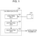
- Fig. 1is a block diagram illustrating a configuration example of the calibration device according to Embodiment 1 of this disclosure.
- a calibration device 100includes an acquiring unit 101 which acquires an image captured by a camera 110 installed on a vehicle, an extracting unit 102 which extracts a point through an image process from the image acquired by the acquiring unit 101, and the calculating unit 103 which calculates an installation parameter of a camera using coordinates of the point extracted by the extracting unit 102.
- Fig. 2is a flowchart illustrating an operation of the calibration device 100.
- Fig. 3is an explanatory diagram illustrating a situation where the acquiring unit 101 in the calibration device 100 acquires an image from the camera 110.
- a first point a and a second point bare on a motion plane 300.
- a straight line 301 which connects the two pointsis not parallel to a moving direction 302 of a vehicle.
- the term "motion plane"refers to a flat plane on which a vehicle travels. The motion plane may be inclined from the horizontal.
- the acquiring unit 101acquires an image captured by the camera 110 from the camera 110, in accordance with an externally provided image acquiring signal (not illustrated).
- an image acquiring signalis input to the acquiring unit 101 at a first image acquiring position illustrated in Fig. 3 .
- the acquiring unit 101acquires an image (a first image), which is an image including the first point a and the second point b captured by the camera 110 at the first image acquiring position (Step S201).
- Fig. 4is an explanatory diagram of the first image acquired by the acquiring unit 101 in the Step S201.
- a point a1corresponds to the first point a in Fig. 3 and a point b1 corresponds to the second point b in Fig. 3 .
- the image acquired by the acquiring unit 101is input to the extracting unit 102.
- the extracting unit 102extracts the first point a and the second point b from the input image through an image process, such as a comparison of pixel brightness in the image.
- the extracting unit 102calculates coordinates of the first point a (first coordinates) and coordinates of the second point b (second coordinates) in the first image (Step S202).
- the image acquiring signalis input to the acquiring unit 101 and the acquiring unit 101 acquires an image (a second image), which is an image including the first point a and the second point b captured by the camera 110 at the second image acquiring position (Step S203).
- Fig. 5is an explanatory diagram of the second image acquired by the acquiring unit 101 in the Step S203.
- a point a2corresponds to the first point a in Fig. 3 and a point b2 corresponds to the second point b in Fig. 3 .
- the image acquired by the acquiring unit 101is input to the extracting unit 102.
- the extracting unit 102performs a similar process to that in the Step S202 and calculates coordinates of the first point a (third coordinates) and coordinates of the second point b (fourth coordinates) in the second image (Step S204).
- the coordinates of the first point a(the coordinates of the point a1 in Fig. 4 ) and the coordinates of the second point b (the coordinates of the point b1 in Fig. 4 ), which are extracted in the Step S202, and the coordinates of the first point a (the coordinates of the point a2 in Fig. 5 ) and the coordinates of the second point b (the coordinates of the point b2 in Fig. 5 ), which are extracted in the Step S204, are input to the calculating unit 103.
- the calculating unit 103calculates an installation parameter of a camera on the basis of a positional relationship between the coordinates of the point a1 and the coordinates of the point b1, a positional relationship between the coordinates of the point a2 and the coordinates of the point b2, a positional relationship between the coordinates of the point a1 and the coordinates of the point a2, and a positional relationship between the coordinates of the point b1 and the coordinates of the point b2.
- the calculating unit 103calculates straight lines from the coordinates of the point a1, the point b1, the point a2, and the point b2 which are extracted by the extracting unit 102.
- the point a1, the point b1, the point a2, and the point b2, which are extracted by the extracting unit 102are illustrated in one image as an example.
- Fig. 6is a diagram for illustrating a process of the calculating unit 103.
- the calculating unit 103calculates a straight line 610 which passes through the coordinates of the point a1 and the point a2, a straight line 611 which passes through the coordinates of the point b1 and the point b2, a straight line 620 which passes through the coordinates of the point a1 and the point b1, and a straight line 621 which passes through the coordinates of the point a2 and the point b2 (Step S205).
- the calculating unit 103calculates an installation parameter of a camera on the basis of the positional relationships of the straight line 610, the straight line 611, the straight line 620, and the straight line 621 (the Step S206) and outputs a calculation result (Step S207).
- Fig. 7is a flowchart illustrating a detailed operation of a camera installation parameter calculating process in the Step S206.
- the calculating unit 103compares the inclination of the straight line 610 with that of the straight line 611 (Step S701) and the inclination of the straight line 620 with that of the straight line 621 (Step S702 or Step S703), and then the camera installation parameter calculating process is executed on the basis of the positional relationships of the straight lines.
- Described hereinafterare examples of the camera installation parameter calculating process depending on whether the inclination of the straight line 610 is equal to or not equal to the inclination of the straight line 611 and whether the inclination of the straight line 620 is equal to or not equal to the inclination of the straight line 621.
- the calculating unit 103calculates an intersection of the straight line 610 and the straight line 611 as a deep vanishing point (the Step S704). In addition, the calculating unit 103 calculates an intersection of the straight line 620 and the straight line 621 as a vanishing point (the Step S705). Then, the calculating unit 103 calculates a straight line which passes through the deep vanishing point and the vanishing point as a vanishing line (the Step S706).
- the calculating unit 103calculates a camera installation parameter using a focal length of the camera 110 on the basis of the positional relationship between the coordinates of the point a1 and the coordinates of the point b1, the positional relationship between the coordinates of the point a2 and the coordinates of the point b2, the positional relationship between the coordinates of the point a1 and the coordinates of the point a2, and the positional relationship between the coordinates of the point b1 and the coordinates of the point b2.
- definitions of the camera installation parameterare as follows: the term “roll angle” refers to a rotation angle whose axis is an optical axis of the camera, the term “pitch angle” refers to a rotation angle whose axis is parallel to the motion plane and perpendicular to the optical axis of the camera, and the term “yawing angle” refers to a rotation angle whose axis is perpendicular to the motion plane.
- the original pointis in the upper left, the X-axis extends rightward and the Y-axis extends downward.
- the calculating unit 103calculates an angle between a straight line parallel to the X-axis and the vanishing line calculated in the Step S706 as the roll angle (the Step S707). Then, the calculating unit 103 calculates the pitch angle using the focal length of the camera 110, the coordinates of the vanishing point calculated in the Step S705, and the roll angle calculated in the Step S707 (the Step S708). Finally, the calculating unit 103 calculates the yawing angle using the focal length of the camera 110, the coordinates of the deep vanishing point calculated in the Step S704, the vanishing line calculated in the Step S706, and the pitch angle calculated in the Step S708 (the Step S709).
- the calibration devicecan obtain the deep vanishing point and the vanishing point at the same time and then calculate the camera installation parameter using the vanishing line which passes through the deep vanishing point and the vanishing point.
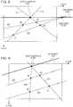
- Step S710 to Step S714A case where the inclination of the straight line 610 is not equal to the inclination of the straight line 611 and the inclination of the straight line 620 is equal to the inclination of the straight line 621 (Step S710 to Step S714)
- the calculating unit 103calculates an intersection of the straight line 610 and the straight line 611 as a deep vanishing point (the Step S710). Then, the calculating unit 103 calculates a straight line which passes through the deep vanishing point and is parallel to the straight line 620 and the straight line 621 as a vanishing line (the Step S711).
- the calculating unit 103calculates an angle between a straight line parallel to the X-axis and the vanishing line calculated in the Step S711 as the roll angle (the Step S712). Then, the calculating unit 103 calculates the pitch angle using the focal length of the camera 110, the coordinates of the deep vanishing point calculated in the Step S710, and the roll angle calculated in the Step S712 (the Step S713). Finally, the calculating unit 103 calculates the yawing angle using the focal length of the camera 110, the coordinates of the deep vanishing point calculated in the Step S710, the vanishing line calculated in the Step S711, and the pitch angle calculated in the Step S713 (the Step S714). (3) A case where the inclination of the straight line 610 is equal to the inclination of the straight line 611 and the inclination of the straight line 620 is not equal to the inclination of the straight line 621 (Step S715 to Step S719)
- the calculating unit 103calculates an intersection of the straight line 620 and the straight line 621 as a vanishing point (the Step S715). Then, the calculating unit 103 calculates a straight line which passes through the vanishing point and is parallel to the straight line 610 and the straight line 611 as a vanishing line (the Step S716).
- the calculating unit 103calculates an angle between a straight line parallel to the X-axis and the vanishing line calculated in the Step S716 as the roll angle (the Step S717). Then, the calculating unit 103 calculates the pitch angle using the focal length of the camera 110, the coordinates of the vanishing point calculated in the Step S715, and the roll angle calculated in the Step S717 (the Step S718).
- the calculating unit 103calculates the yawing angle using the focal length of the camera 110, the coordinates of a deep vanishing point which is defined to lie at an infinite distance along the vanishing line calculated in the Step S716 in the direction from the point a1 toward the point a2, the vanishing line calculated in the Step S716, and the pitch angle calculated in the Step S718 (the Step S719).
- the inclination of the straight line 610is equal to the inclination of the straight line 611 and the inclination of the straight line 620 is equal to the inclination of the straight line 621 (Step S720 to Step S722)
- FIG. 11An example of the positional relationship of the point a1, the point b1, the point a2, and the point b2 is illustrated in Fig. 11 .
- the calculating unit 103defines the pitch angle as 90 degrees (the Step S720). Further, when the pitch angle is 90 degrees, it is impossible to distinguish changes in the roll angle from changes in the yawing angle; therefore, the roll angle is defined as 0 degrees in this case (the Step S721).
- the calculating unit 103calculates an angle 1101 formed by a straight line 1100 parallel to the Y-axis, the straight line 610, and the straight line 611, as the yawing angle (the Step S722).
- two points on the motion planeare used in the above description, two points on another plane parallel to the motion plane, such as tops of poles having the same height, may be similarly used to obtain the camera installation parameter.
- the calibration device according to Embodiment 1 of this disclosuremay be realized by using dedicated hardware.
- the calibration devicemay be realized by storing a program which executes the function in a computer-readable recording medium and making a computer read and execute the program.
- Such a storage mediummay be mounted on the camera 110 to provide a camera having a calibration function.
- the first point a and the second point b on the motion plane 300may be markers having a specific shape and color to enhance the process accuracy of the extracting unit 102.
- the distance between the first image acquiring position and the second image acquiring positionis not particularly limited, as long as both the first point a and the second point b are captured in each of the first image and the second image.
- the distancemay be 50 cm or 10 m.
- the movable bodymoves in a straight line on a level plane in this embodiment, a perfectly straight trajectory is not essential for this disclosure.
- the calculation accuracy of the camera installation parameterdepends on the degree of straightness and levelness. Therefore, the degree of straightness and levelness is not limited, as long as the calculation accuracy of the camera installation parameter reaches a certain degree required by an application or the like; for example, the movable body may zigzag or move over an uneven or curved surface.
- a straight line which passes through two feature points on an image captured before the vehicle moves straight and a straight line which passes through two feature points on an image captured after the vehicle moves straight, which correspond to the two points before the vehicle moves straightare parallel to each other in the real space.
- a straight line which passes through one of the two feature points before the vehicle moves straight and the corresponding feature point after the vehicle moves straightare also parallel to a straight line which passes through another of the two feature points before the vehicle moves straight and the corresponding feature point after the vehicle moves straight in the real space.
- the installation parameter of a cameracan be calculated using the calibration device according to Embodiment 1 of this disclosure, without storing graphical features of road markings or the like in advance or without using another technique.
- Fig. 12is a block diagram illustrating a configuration example of the calibration device according to Embodiment 2 of this disclosure.
- a calibration device 1200includes an acquiring unit 1201 which acquires an image captured by the camera 110 installed on a vehicle, an extracting unit 1202 which extracts a point through an image process from the image acquired by the acquiring unit 1201, a calculating unit 1203 which calculates an installation parameter of a camera using coordinates of the point extracted by the extracting unit 1202, and a driving status determining unit 1204 which determines a driving status of the vehicle.
- the acquiring unit 1201acquires an image captured by the camera 110 from the camera 110, in accordance with an externally provided image acquiring signal.
- the extracting unit 1202extracts a feature point from the image and performs an image process to extract corresponding feature points from different images by, for example, block matching.
- the calculating unit 1203calculates an installation parameter of a camera on the basis of the corresponding feature points in different images which are output from the extracting unit 1202.
- the driving status determining unit 1204determines a driving status of the vehicle on the basis of driving distance information, travelling direction information, and motion surface information, which are input from the vehicle.
- driving distance informationrefers to information for determining whether the vehicle moves a certain distance or not. Such information is, for example, provided by a driving distance meter of the vehicle.
- traveling direction informationrefers to information for determining whether the vehicle moves straight or not. Such information is, for example, provided by a steering angle sensor of the vehicle.
- motion surface informationrefers to information for determining whether the motion surface is plane or not. Such information is, for example, provided by an angle sensor, a gyro, or the like of the vehicle.
- Fig. 13is a flowchart illustrating an operation of the calibration device 1200 according to Embodiment 2 of this disclosure.
- the driving status determining unit 1204determines whether the status is suitable for executing calibration or not (Step S1301). In other words, the driving status determining unit 1204 determines whether the image which the acquiring unit 1201 acquires from the camera 110 is an image capturing the motion plane or not. Specifically, the driving status determining unit 1204 determines whether a driving condition 1, "the vehicle drives a certain distance, such as 5 meters, and the moving surface information does not change during the drive" is satisfied or not. This determination step is repeated until the driving condition 1 is satisfied. When the driving condition 1 is satisfied, an input image process is then performed (the Step S1302).
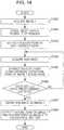
- Fig. 14is a flowchart illustrating details of the input image process of the Step S1302.
- the acquiring unit 1201acquires a first image (hereinafter, referred to as an image 1) (Step S1401).
- the image acquired by the acquiring unit 1201is input to the extracting unit 1202.
- the extracting unit 1202divides the image 1 acquired from the acquiring unit 1201 into a plurality of regions (Step S1402).
- one feature pointis extracted from each of the divided regions through an image process (Step S1403).
- Harris methodmay be employed and a pixel which has the largest value in each divided region is extracted as a feature point of the region.
- Fig. 15illustrates the image 1 where the image is divided into 16 regions and from which 16 feature points are extracted.
- the feature pointsare represented by black dots such as the point a1 and the point b1.
- the acquiring unit 1201acquires at least one image (hereinafter, referred to as a sub-image) from the camera 110 and the extracting unit 1202 performs an image process to extract feature points from the sub-image which correspond to those extracted from the image 1 by, for example, block matching (Step S1404 to Step S1406).
- a sub-imageat least one image
- the extracting unit 1202performs an image process to extract feature points from the sub-image which correspond to those extracted from the image 1 by, for example, block matching (Step S1404 to Step S1406).
- the driving status determining unit 1204determines whether the vehicle drives the predetermined distance or not.
- the extracting unit 1202defines the last sub-image which is acquired by the acquiring unit 1201, as the image 2 (Step S1407), and outputs the feature points extracted from the image 1 and the feature points extracted from the image 2 to the calculating unit 1203 (Step S1408), whereby the input image process ends.
- Fig. 16illustrates the image 2 obtained through the input image process.
- White squares in Fig. 16represent the feature points corresponding to the feature points extracted from the image 1.
- the feature point a2corresponds to the point a1 in the image 1
- the feature point b2corresponds to the point b1 in the image 1.
- Each one of the feature points in Fig. 16corresponds to respective feature point in Fig. 15 .
- the driving status determining unit 1204determines whether to start a vanishing line calculating process or not (Step S1303). In other words, whether the vehicle moves straight over the motion plane after the driving condition 1 is satisfied or not is determined. Specifically, whether a driving condition 2 "the motion surface information does not change from the value at the time when the driving condition 1 is satisfied and a value of the steering angle sensor shows the vehicle moves straight after the driving condition 1 is satisfied" is satisfied or not is determined.
- Step S1304When the driving condition 2 is not satisfied, the process returns to the determination of whether the driving condition 1 is satisfied or not.
- the calculating unit 1203then performs a vanishing line calculating process (Step S1304).
- Figs. 17, 18 , and 19illustrate an example of the vanishing line calculating process.
- Fig. 17the feature points of the image 1 and the feature points of the image 2 corresponding to the feature points of the image 1 are illustrated in one image.
- the calculating unit 1203calculates straight lines each of which passes through one of the feature points in the image 1 ( Fig. 15 ) and one of the feature points in the image 2 ( Fig. 16 ) corresponding to the one feature point in the image 1 and calculates the intersection of the straight lines as a deep vanishing point.
- a white circlerepresents the calculated deep vanishing point.
- the calculating unit 1203selects two feature points in the image 1 and calculates a straight line which passes through the two feature points.
- the calculating unit 1203also calculates a straight line which passes through two feature points in the image 2 corresponding to the two feature points selected in the image 1. Then, the calculating unit 1203 calculates the intersection of the straight line calculated in the image 1 and the straight line calculated in the image 2 as a vanishing point. This process is performed for all pairs of the feature points. In Fig. 19 , triangles represent the calculated vanishing points.
- the calculating unit 1203calculates a straight line which passes through the deep vanishing point and the largest number of the vanishing points as the vanishing line, using Hough transform.
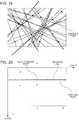
- Fig. 20is an explanatory diagram illustrating the calculated deep vanishing point, the calculated vanishing points, and the vanishing line calculated through Hough transform.
- the vanishing points on the vanishing line in Fig. 20are calculated from feature points which are on the motion plane or on a plane parallel to the motion plane and which are located in a manner such that the line segment connecting the feature points is not parallel to the moving direction of the vehicle.
- the calculating unit 1203calculates a roll angle, a pitch angle, and a yawing angle, which are camera installation parameters, using the coordinates of the deep vanishing point, the vanishing line, and the focal length of the camera 110, as described in Embodiment 1 (Step S1305).
- the calculating unit 1203calculates an angle between a straight line parallel to the X-axis and the vanishing line calculated in the Step S1304 as a roll angle. Then, the calculating unit 1203 calculates a pitch angle using the focal length of the camera 110, the coordinates of the deep vanishing point, and the roll angle. Finally, the calculating unit 1203 calculates a yawing angle using the focal length of the camera 110, the coordinates of the deep vanishing point, the vanishing line calculated in the Step S1304, and the pitch angle.
- the driving status determining unit 1204may calculate the driving distance, the travelling direction, and the levelness of the motion surface on the basis of information from the GPS (global positioning system).
- the calibration device 1200may include a CPU (central processing unit), a RAM (random access memory), and a ROM (read only memory) and be realized as a program stored in a CPU-readable storage medium performing processes of the units.
- a CPUcentral processing unit
- RAMrandom access memory
- ROMread only memory
- the calculating unit 1203may calculate the vanishing points only in a part of the image which captures the motion plane.
- the calculating unit 1203 illustrated in Fig. 12may be mounted on the camera to provide a camera having a calibration function.
- the calibration devicecan calculate a camera installation even when the motion plane in the image is not identified.
- This disclosurecan be applied to, for example, an on-vehicle camera which is installed on a vehicle and assists driving.
Landscapes
- Engineering & Computer Science (AREA)
- Computer Vision & Pattern Recognition (AREA)
- Physics & Mathematics (AREA)
- General Physics & Mathematics (AREA)
- Theoretical Computer Science (AREA)
- Biomedical Technology (AREA)
- Health & Medical Sciences (AREA)
- General Health & Medical Sciences (AREA)
- Multimedia (AREA)
- Signal Processing (AREA)
- Image Analysis (AREA)
- Studio Devices (AREA)
- Image Processing (AREA)
- Testing, Inspecting, Measuring Of Stereoscopic Televisions And Televisions (AREA)
Description
- This disclosure relates to a calibration technique for calculating installation parameters of a camera on the basis of images captured by the camera installed on a movable body.
- In recent years, a technique has been spread where a camera installed on a vehicle is used to measure distances between the vehicle and objects in front of or to the rear of the vehicle and, when needed, the driver is alerted by an alarm. In order to accurately measure the distance between the vehicle and the object, it is necessary to calculate (calibrate) an installation position and an installation angle of a camera with respect to the vehicle.
- In general, as a calibration technique for calculating an installation angle of a camera with respect to the vehicle, a technique utilizing a point (a vanishing point) at which straight lines which are parallel in real space intersect with each other in image space is known.
- In a calibration technique utilizing a vanishing point, the installation angle of the camera is calculated using at least two vanishing points: a vanishing point (a deep vanishing point) which is calculated using lines parallel to a travelling direction of the vehicle and a vanishing point which is calculated using other lines parallel to another direction.
- In the following description, the installation angle of the camera with respect to the vehicle is referred to as an installation parameter of the camera.
- With regard to a calibration technique utilizing a vanishing point to calculate an installation parameter of the camera, there is a technique where two pairs of parallel lines are extracted using a road marking of which graphical features are stored in advance, and then two vanishing points are calculated from the extracted two pairs of parallel lines (see, for example, Japanese Unexamined Patent Application Publication No.
2008-11174 2010/146695 ). Further examples of methods for extracting parameters from a sequence of captured images are disclosed inUS 6,192,145 B1 ,WO 2009/142921 A2 ,DARIUS BURSCHKA ETAL, "Direct Pose Estimation with a Monocular Camera", ROBOT VISION; [LECTURE NOTES IN COMPUTER SCIENCE], SPRINGER BERLIN HEIDELBERG, BERLIN, HEIDELBERG, PAGE(S) 440 - 453, and KAESS M ET AL, "Flow separation for fast and robust stereo odometry", 2009 IEEE INTERNATIONAL CONFERENCE ON ROBOTICS AND AUTOMATION : (ICRA); KOBE, JAPAN, 12 - 17 MAY 2009, IEEE, PISCATAWAY, NJ, USA, (20090512), PAGE 3539 - 3544. - In the technique described in the above-mentioned Japanese Unexamined Patent Application Publication No.
2008-11174 - In addition, in the technique described in International Publication No.
2010/146695 , although a deep vanishing point can be calculated, another vanishing point cannot be calculated; therefore, an installation parameter of a camera cannot be calculated with the technique described in International Publication No.2010/146695 alone. - Thus, a non-limiting exemplary embodiment of the present disclosure provides a calibration device, a method for implementing calibration, and a camera for a movable body and a storage medium with a calibration function which are capable of calculating an installation parameter of the camera without storing graphical features of road markings in advance or without requiring another technique.
- It should be noted that general or specific embodiments may be realized as a system, a method, an integrated circuit, a computer program, storage media, or any elective combination thereof.
- According to the present disclosure, an installation parameter of a camera can be calculated without storing graphical features of road markings in advance or without requiring another technique.
Fig. 1 is a block diagram illustrating a configuration example of a calibration device according toEmbodiment 1 of this disclosure.Fig. 2 is a flowchart illustrating an operation example of the calibration device according toEmbodiment 1 of this disclosure.Fig. 3 is an explanatory diagram illustrating a situation where the calibration device according toEmbodiment 1 of this disclosure acquires an image from a camera.Fig. 4 illustrates a first image which is captured at a first timing according toEmbodiment 1 of this disclosure.Fig. 5 illustrates a second image which is captured at a second timing according toEmbodiment 1 of this disclosure.Fig. 6 is a conceptual diagram illustrating an operation of a calculatingunit 103 according toEmbodiment 1 of this disclosure.Fig. 7 is a flowchart illustrating a detailed operation example of a camera installation parameter calculating process of Step S206 according toEmbodiment 1 of this disclosure.Fig. 8 is a first explanatory diagram illustrating a process of the calculatingunit 103 according toEmbodiment 1 of this disclosure.Fig. 9 is a second explanatory diagram illustrating the process of the calculatingunit 103 according toEmbodiment 1 of this disclosure.Fig. 10 is a third explanatory diagram illustrating the process of the calculatingunit 103 according toEmbodiment 1 of this disclosure.Fig. 11 is a fourth explanatory diagram illustrating the process of the calculatingunit 103 according toEmbodiment 1 of this disclosure.Fig. 12 is a block diagram illustrating a configuration example of a calibration device according toEmbodiment 2 of this disclosure.Fig. 13 is a flowchart illustrating an operation example of the calibration device according toEmbodiment 2 of this disclosure.Fig. 14 is a flowchart illustrating a detailed operation example of an input image process of Step S1302 according toEmbodiment 2 of this disclosure.Fig. 15 illustrates animage 1 of the calibration device according toEmbodiment 2 of this disclosure.Fig. 16 illustrates animage 2 of the calibration device according toEmbodiment 2 of this disclosure.Fig. 17 is a first explanatory diagram illustrating an example of a vanishing line calculating process according toEmbodiment 2 of this disclosure.Fig. 18 is a second explanatory diagram illustrating an example of the vanishing line calculating process according toEmbodiment 2 of this disclosure.Fig. 19 is a third explanatory diagram illustrating an example of the vanishing line calculating process according toEmbodiment 2 of this disclosure.Fig. 20 is an explanatory diagram illustrating an example of a vanishing line according toEmbodiment 2 of this disclosure.- Hereinafter, Embodiments of this disclosure will be described with reference to the drawings. Note that although a vehicle is given as an example of a movable body in the Embodiments of this disclosure, the movable body is not limited to a vehicle.
- Hereinafter, a calibration device according to
Embodiment 1 of this disclosure will be described. Fig. 1 is a block diagram illustrating a configuration example of the calibration device according toEmbodiment 1 of this disclosure.- In
Fig. 1 , acalibration device 100 includes an acquiringunit 101 which acquires an image captured by acamera 110 installed on a vehicle, an extractingunit 102 which extracts a point through an image process from the image acquired by the acquiringunit 101, and the calculatingunit 103 which calculates an installation parameter of a camera using coordinates of the point extracted by the extractingunit 102. Fig. 2 is a flowchart illustrating an operation of thecalibration device 100.Fig. 3 is an explanatory diagram illustrating a situation where the acquiringunit 101 in thecalibration device 100 acquires an image from thecamera 110.- In
Fig. 3 , a first point a and a second point b are on amotion plane 300. Astraight line 301 which connects the two points is not parallel to a movingdirection 302 of a vehicle. Here, the term "motion plane" refers to a flat plane on which a vehicle travels. The motion plane may be inclined from the horizontal. - The acquiring
unit 101 acquires an image captured by thecamera 110 from thecamera 110, in accordance with an externally provided image acquiring signal (not illustrated). InEmbodiment 1, an image acquiring signal is input to the acquiringunit 101 at a first image acquiring position illustrated inFig. 3 . The acquiringunit 101 acquires an image (a first image), which is an image including the first point a and the second point b captured by thecamera 110 at the first image acquiring position (Step S201). Fig. 4 is an explanatory diagram of the first image acquired by the acquiringunit 101 in the Step S201. InFig. 4 , a point a1 corresponds to the first point a inFig. 3 and a point b1 corresponds to the second point b inFig. 3 .- The image acquired by the acquiring
unit 101 is input to the extractingunit 102. The extractingunit 102 extracts the first point a and the second point b from the input image through an image process, such as a comparison of pixel brightness in the image. In other words, the extractingunit 102 calculates coordinates of the first point a (first coordinates) and coordinates of the second point b (second coordinates) in the first image (Step S202). - Then, after the vehicle moves straight forward, at a second image acquiring position illustrated in
Fig. 3 , the image acquiring signal is input to the acquiringunit 101 and the acquiringunit 101 acquires an image (a second image), which is an image including the first point a and the second point b captured by thecamera 110 at the second image acquiring position (Step S203). Fig. 5 is an explanatory diagram of the second image acquired by the acquiringunit 101 in the Step S203. InFig. 5 , a point a2 corresponds to the first point a inFig. 3 and a point b2 corresponds to the second point b inFig. 3 .- The image acquired by the acquiring
unit 101 is input to the extractingunit 102. The extractingunit 102 performs a similar process to that in the Step S202 and calculates coordinates of the first point a (third coordinates) and coordinates of the second point b (fourth coordinates) in the second image (Step S204). - The coordinates of the first point a (the coordinates of the point a1 in
Fig. 4 ) and the coordinates of the second point b (the coordinates of the point b1 inFig. 4 ), which are extracted in the Step S202, and the coordinates of the first point a (the coordinates of the point a2 inFig. 5 ) and the coordinates of the second point b (the coordinates of the point b2 inFig. 5 ), which are extracted in the Step S204, are input to the calculatingunit 103. - The calculating
unit 103 calculates an installation parameter of a camera on the basis of a positional relationship between the coordinates of the point a1 and the coordinates of the point b1, a positional relationship between the coordinates of the point a2 and the coordinates of the point b2, a positional relationship between the coordinates of the point a1 and the coordinates of the point a2, and a positional relationship between the coordinates of the point b1 and the coordinates of the point b2. - The calculating
unit 103 calculates straight lines from the coordinates of the point a1, the point b1, the point a2, and the point b2 which are extracted by the extractingunit 102. InFig. 6 , the point a1, the point b1, the point a2, and the point b2, which are extracted by the extractingunit 102, are illustrated in one image as an example.Fig. 6 is a diagram for illustrating a process of the calculatingunit 103. The calculatingunit 103 calculates astraight line 610 which passes through the coordinates of the point a1 and the point a2, astraight line 611 which passes through the coordinates of the point b1 and the point b2, astraight line 620 which passes through the coordinates of the point a1 and the point b1, and astraight line 621 which passes through the coordinates of the point a2 and the point b2 (Step S205). - The calculating
unit 103 calculates an installation parameter of a camera on the basis of the positional relationships of thestraight line 610, thestraight line 611, thestraight line 620, and the straight line 621 (the Step S206) and outputs a calculation result (Step S207). Fig. 7 is a flowchart illustrating a detailed operation of a camera installation parameter calculating process in the Step S206.- The calculating
unit 103 compares the inclination of thestraight line 610 with that of the straight line 611 (Step S701) and the inclination of thestraight line 620 with that of the straight line 621 (Step S702 or Step S703), and then the camera installation parameter calculating process is executed on the basis of the positional relationships of the straight lines. - Described hereinafter are examples of the camera installation parameter calculating process depending on whether the inclination of the
straight line 610 is equal to or not equal to the inclination of thestraight line 611 and whether the inclination of thestraight line 620 is equal to or not equal to the inclination of thestraight line 621. - (1) A case where the inclination of the
straight line 610 is not equal to the inclination of thestraight line 611 and the inclination of thestraight line 620 is not equal to the inclination of the straight line 621 (Step S704 to Step S709) - An example of the positional relationship of the point a1, the point b1, the point a2, and the point b2 is illustrated in
Fig. 8 . The calculatingunit 103 calculates an intersection of thestraight line 610 and thestraight line 611 as a deep vanishing point (the Step S704). In addition, the calculatingunit 103 calculates an intersection of thestraight line 620 and thestraight line 621 as a vanishing point (the Step S705). Then, the calculatingunit 103 calculates a straight line which passes through the deep vanishing point and the vanishing point as a vanishing line (the Step S706). - Details of a method for calculating a parameter of a camera using a vanishing point and a vanishing line are described in publications (such asLing-Ling Wang, "Camera Calibration by Vanishing Lines for 3D Computer Vision", IEEE Transactions on Pattern Analysis and Machine Intelligence, Vol.13, No.4, April 1991, pp 370-376).
- Although no detailed description is given here, the calculating
unit 103 calculates a camera installation parameter using a focal length of thecamera 110 on the basis of the positional relationship between the coordinates of the point a1 and the coordinates of the point b1, the positional relationship between the coordinates of the point a2 and the coordinates of the point b2, the positional relationship between the coordinates of the point a1 and the coordinates of the point a2, and the positional relationship between the coordinates of the point b1 and the coordinates of the point b2. - In this Embodiment, definitions of the camera installation parameter are as follows: the term "roll angle" refers to a rotation angle whose axis is an optical axis of the camera, the term "pitch angle" refers to a rotation angle whose axis is parallel to the motion plane and perpendicular to the optical axis of the camera, and the term "yawing angle" refers to a rotation angle whose axis is perpendicular to the motion plane.
- Further, in the coordinate system of the image space, the original point is in the upper left, the X-axis extends rightward and the Y-axis extends downward.
- The calculating
unit 103 calculates an angle between a straight line parallel to the X-axis and the vanishing line calculated in the Step S706 as the roll angle (the Step S707). Then, the calculatingunit 103 calculates the pitch angle using the focal length of thecamera 110, the coordinates of the vanishing point calculated in the Step S705, and the roll angle calculated in the Step S707 (the Step S708). Finally, the calculatingunit 103 calculates the yawing angle using the focal length of thecamera 110, the coordinates of the deep vanishing point calculated in the Step S704, the vanishing line calculated in the Step S706, and the pitch angle calculated in the Step S708 (the Step S709). - As described above, in a case where the inclination of the
straight line 610 is different from that of thestraight line 611 and the inclination of thestraight line 620 is different from that of thestraight line 621, the calibration device according toEmbodiment 1 of this disclosure can obtain the deep vanishing point and the vanishing point at the same time and then calculate the camera installation parameter using the vanishing line which passes through the deep vanishing point and the vanishing point.
(2) A case where the inclination of thestraight line 610 is not equal to the inclination of thestraight line 611 and the inclination of thestraight line 620 is equal to the inclination of the straight line 621 (Step S710 to Step S714) - An example of the positional relationship of the point a1, the point b1, the point a2, and the point b2 is illustrated in
Fig. 9 . The calculatingunit 103 calculates an intersection of thestraight line 610 and thestraight line 611 as a deep vanishing point (the Step S710). Then, the calculatingunit 103 calculates a straight line which passes through the deep vanishing point and is parallel to thestraight line 620 and thestraight line 621 as a vanishing line (the Step S711). - The calculating
unit 103 calculates an angle between a straight line parallel to the X-axis and the vanishing line calculated in the Step S711 as the roll angle (the Step S712). Then, the calculatingunit 103 calculates the pitch angle using the focal length of thecamera 110, the coordinates of the deep vanishing point calculated in the Step S710, and the roll angle calculated in the Step S712 (the Step S713). Finally, the calculatingunit 103 calculates the yawing angle using the focal length of thecamera 110, the coordinates of the deep vanishing point calculated in the Step S710, the vanishing line calculated in the Step S711, and the pitch angle calculated in the Step S713 (the Step S714).
(3) A case where the inclination of thestraight line 610 is equal to the inclination of thestraight line 611 and the inclination of thestraight line 620 is not equal to the inclination of the straight line 621 (Step S715 to Step S719) - An example of the positional relationship of the point a1, the point b1, the point a2, and the point b2 is illustrated in
Fig. 10 . The calculatingunit 103 calculates an intersection of thestraight line 620 and thestraight line 621 as a vanishing point (the Step S715). Then, the calculatingunit 103 calculates a straight line which passes through the vanishing point and is parallel to thestraight line 610 and thestraight line 611 as a vanishing line (the Step S716). - The calculating
unit 103 calculates an angle between a straight line parallel to the X-axis and the vanishing line calculated in the Step S716 as the roll angle (the Step S717). Then, the calculatingunit 103 calculates the pitch angle using the focal length of thecamera 110, the coordinates of the vanishing point calculated in the Step S715, and the roll angle calculated in the Step S717 (the Step S718). - Finally, the calculating
unit 103 calculates the yawing angle using the focal length of thecamera 110, the coordinates of a deep vanishing point which is defined to lie at an infinite distance along the vanishing line calculated in the Step S716 in the direction from the point a1 toward the point a2, the vanishing line calculated in the Step S716, and the pitch angle calculated in the Step S718 (the Step S719).
(4) A case where the inclination of thestraight line 610 is equal to the inclination of thestraight line 611 and the inclination of thestraight line 620 is equal to the inclination of the straight line 621 (Step S720 to Step S722) - An example of the positional relationship of the point a1, the point b1, the point a2, and the point b2 is illustrated in
Fig. 11 . - When the inclination of the
straight line 610 is equal to that of thestraight line 611 and the inclination of thestraight line 620 is equal to that of thestraight line 621, the camera is installed in a manner such that the optical axis thereof is perpendicular to the motion plane; therefore, the calculatingunit 103 defines the pitch angle as 90 degrees (the Step S720). Further, when the pitch angle is 90 degrees, it is impossible to distinguish changes in the roll angle from changes in the yawing angle; therefore, the roll angle is defined as 0 degrees in this case (the Step S721). - The calculating
unit 103 calculates anangle 1101 formed by astraight line 1100 parallel to the Y-axis, thestraight line 610, and thestraight line 611, as the yawing angle (the Step S722). - Note that the method for calculating an installation parameter of a camera which has been described above is an example, and another method may be employed to calculate the installation parameter of a camera using the coordinates of the points.
- In addition, although the two points on the motion plane are used in the above description, two points on another plane parallel to the motion plane, such as tops of poles having the same height, may be similarly used to obtain the camera installation parameter.
- The calibration device according to
Embodiment 1 of this disclosure may be realized by using dedicated hardware. Alternatively, the calibration device may be realized by storing a program which executes the function in a computer-readable recording medium and making a computer read and execute the program. - Further, such a storage medium may be mounted on the
camera 110 to provide a camera having a calibration function. - The first point a and the second point b on the
motion plane 300 may be markers having a specific shape and color to enhance the process accuracy of the extractingunit 102. - The distance between the first image acquiring position and the second image acquiring position is not particularly limited, as long as both the first point a and the second point b are captured in each of the first image and the second image. For example, the distance may be 50 cm or 10 m.
- Note that although the movable body moves in a straight line on a level plane in this embodiment, a perfectly straight trajectory is not essential for this disclosure. The calculation accuracy of the camera installation parameter depends on the degree of straightness and levelness. Therefore, the degree of straightness and levelness is not limited, as long as the calculation accuracy of the camera installation parameter reaches a certain degree required by an application or the like; for example, the movable body may zigzag or move over an uneven or curved surface.
- When the camera is in a datum position, a straight line which passes through two feature points on an image captured before the vehicle moves straight and a straight line which passes through two feature points on an image captured after the vehicle moves straight, which correspond to the two points before the vehicle moves straight, are parallel to each other in the real space. In addition, a straight line which passes through one of the two feature points before the vehicle moves straight and the corresponding feature point after the vehicle moves straight are also parallel to a straight line which passes through another of the two feature points before the vehicle moves straight and the corresponding feature point after the vehicle moves straight in the real space. Using the images including the two feature points which define the two pairs of parallel lines in the real space, the installation parameter of a camera can be calculated.
- Accordingly, as described above, the installation parameter of a camera can be calculated using the calibration device according to
Embodiment 1 of this disclosure, without storing graphical features of road markings or the like in advance or without using another technique. - Hereinafter, a calibration device according to
Embodiment 2 of this disclosure will be described. Fig. 12 is a block diagram illustrating a configuration example of the calibration device according toEmbodiment 2 of this disclosure. InFig. 12 , acalibration device 1200 includes an acquiringunit 1201 which acquires an image captured by thecamera 110 installed on a vehicle, an extractingunit 1202 which extracts a point through an image process from the image acquired by the acquiringunit 1201, a calculatingunit 1203 which calculates an installation parameter of a camera using coordinates of the point extracted by the extractingunit 1202, and a drivingstatus determining unit 1204 which determines a driving status of the vehicle.- The acquiring
unit 1201 acquires an image captured by thecamera 110 from thecamera 110, in accordance with an externally provided image acquiring signal. - The extracting
unit 1202 extracts a feature point from the image and performs an image process to extract corresponding feature points from different images by, for example, block matching. - The calculating
unit 1203 calculates an installation parameter of a camera on the basis of the corresponding feature points in different images which are output from the extractingunit 1202. - The driving
status determining unit 1204 determines a driving status of the vehicle on the basis of driving distance information, travelling direction information, and motion surface information, which are input from the vehicle. The term "driving distance information" refers to information for determining whether the vehicle moves a certain distance or not. Such information is, for example, provided by a driving distance meter of the vehicle. The term "travelling direction information" refers to information for determining whether the vehicle moves straight or not. Such information is, for example, provided by a steering angle sensor of the vehicle. The term "motion surface information" refers to information for determining whether the motion surface is plane or not. Such information is, for example, provided by an angle sensor, a gyro, or the like of the vehicle. - An operation of the
calibration device 1200 having the above-described configuration according toEmbodiment 2 of this disclosure will be described with reference to drawings. Fig. 13 is a flowchart illustrating an operation of thecalibration device 1200 according toEmbodiment 2 of this disclosure.- When a process starts, the driving
status determining unit 1204 determines whether the status is suitable for executing calibration or not (Step S1301). In other words, the drivingstatus determining unit 1204 determines whether the image which the acquiringunit 1201 acquires from thecamera 110 is an image capturing the motion plane or not. Specifically, the drivingstatus determining unit 1204 determines whether a drivingcondition 1, "the vehicle drives a certain distance, such as 5 meters, and the moving surface information does not change during the drive" is satisfied or not. This determination step is repeated until the drivingcondition 1 is satisfied. When the drivingcondition 1 is satisfied, an input image process is then performed (the Step S1302). Fig. 14 is a flowchart illustrating details of the input image process of the Step S1302. First, the acquiringunit 1201 acquires a first image (hereinafter, referred to as an image 1) (Step S1401). The image acquired by the acquiringunit 1201 is input to the extractingunit 1202. The extractingunit 1202 divides theimage 1 acquired from the acquiringunit 1201 into a plurality of regions (Step S1402).- Then, one feature point is extracted from each of the divided regions through an image process (Step S1403). Specifically, for example, Harris method may be employed and a pixel which has the largest value in each divided region is extracted as a feature point of the region.
Fig. 15 illustrates theimage 1 where the image is divided into 16 regions and from which 16 feature points are extracted. In the drawing, the feature points are represented by black dots such as the point a1 and the point b1.- Then, until the vehicle drives a predetermined distance, for example, 1 meter, the acquiring
unit 1201 acquires at least one image (hereinafter, referred to as a sub-image) from thecamera 110 and the extractingunit 1202 performs an image process to extract feature points from the sub-image which correspond to those extracted from theimage 1 by, for example, block matching (Step S1404 to Step S1406). - The driving
status determining unit 1204 determines whether the vehicle drives the predetermined distance or not. When the vehicle drives the predetermined distance, the extractingunit 1202 defines the last sub-image which is acquired by the acquiringunit 1201, as the image 2 (Step S1407), and outputs the feature points extracted from theimage 1 and the feature points extracted from theimage 2 to the calculating unit 1203 (Step S1408), whereby the input image process ends. Fig. 16 illustrates theimage 2 obtained through the input image process. White squares inFig. 16 represent the feature points corresponding to the feature points extracted from theimage 1. InFig. 16 , the feature point a2 corresponds to the point a1 in theimage 1, and the feature point b2 corresponds to the point b1 in theimage 1.- Each one of the feature points in
Fig. 16 corresponds to respective feature point inFig. 15 . - After the input image process, the driving
status determining unit 1204 determines whether to start a vanishing line calculating process or not (Step S1303). In other words, whether the vehicle moves straight over the motion plane after the drivingcondition 1 is satisfied or not is determined. Specifically, whether a drivingcondition 2 "the motion surface information does not change from the value at the time when the drivingcondition 1 is satisfied and a value of the steering angle sensor shows the vehicle moves straight after the drivingcondition 1 is satisfied" is satisfied or not is determined. - When the driving
condition 2 is not satisfied, the process returns to the determination of whether the drivingcondition 1 is satisfied or not. When the drivingcondition 2 is satisfied, the calculatingunit 1203 then performs a vanishing line calculating process (Step S1304). Figs. 17, 18 , and19 illustrate an example of the vanishing line calculating process. InFig. 17 , the feature points of theimage 1 and the feature points of theimage 2 corresponding to the feature points of theimage 1 are illustrated in one image.- The calculating
unit 1203 calculates straight lines each of which passes through one of the feature points in the image 1 (Fig. 15 ) and one of the feature points in the image 2 (Fig. 16 ) corresponding to the one feature point in theimage 1 and calculates the intersection of the straight lines as a deep vanishing point. InFig. 18 , a white circle represents the calculated deep vanishing point. - In addition, the calculating
unit 1203 selects two feature points in theimage 1 and calculates a straight line which passes through the two feature points. The calculatingunit 1203 also calculates a straight line which passes through two feature points in theimage 2 corresponding to the two feature points selected in theimage 1. Then, the calculatingunit 1203 calculates the intersection of the straight line calculated in theimage 1 and the straight line calculated in theimage 2 as a vanishing point. This process is performed for all pairs of the feature points. InFig. 19 , triangles represent the calculated vanishing points. - Then, the calculating
unit 1203 calculates a straight line which passes through the deep vanishing point and the largest number of the vanishing points as the vanishing line, using Hough transform. Fig. 20 is an explanatory diagram illustrating the calculated deep vanishing point, the calculated vanishing points, and the vanishing line calculated through Hough transform. The vanishing points on the vanishing line inFig. 20 are calculated from feature points which are on the motion plane or on a plane parallel to the motion plane and which are located in a manner such that the line segment connecting the feature points is not parallel to the moving direction of the vehicle.- The calculating
unit 1203 calculates a roll angle, a pitch angle, and a yawing angle, which are camera installation parameters, using the coordinates of the deep vanishing point, the vanishing line, and the focal length of thecamera 110, as described in Embodiment 1 (Step S1305). - The calculating
unit 1203 calculates an angle between a straight line parallel to the X-axis and the vanishing line calculated in the Step S1304 as a roll angle. Then, the calculatingunit 1203 calculates a pitch angle using the focal length of thecamera 110, the coordinates of the deep vanishing point, and the roll angle. Finally, the calculatingunit 1203 calculates a yawing angle using the focal length of thecamera 110, the coordinates of the deep vanishing point, the vanishing line calculated in the Step S1304, and the pitch angle. - Note that in
Fig. 12 , the drivingstatus determining unit 1204 may calculate the driving distance, the travelling direction, and the levelness of the motion surface on the basis of information from the GPS (global positioning system). - Further, in the block diagram of
Fig. 12 illustrating the configuration of thecalibration device 1200, thecalibration device 1200 may include a CPU (central processing unit), a RAM (random access memory), and a ROM (read only memory) and be realized as a program stored in a CPU-readable storage medium performing processes of the units. - The calculating
unit 1203 may calculate the vanishing points only in a part of the image which captures the motion plane. - Further, the calculating
unit 1203 illustrated inFig. 12 may be mounted on the camera to provide a camera having a calibration function. - In general, a large proportion of the image consists of the motion plane; therefore, most of the feature points are extracted from the image of the motion plane. Therefore, the straight line which passes through the deep vanishing point and the largest number of the vanishing points, i.e., the vanishing line can be said to be determined on the basis of the feature points in the motion plane. Accordingly, the calibration device according to
Embodiment 2 of this disclosure can calculate a camera installation even when the motion plane in the image is not identified. - This disclosure can be applied to, for example, an on-vehicle camera which is installed on a vehicle and assists driving.
Claims (4)
- A calibration device comprising:an acquirer (101) adapted to acquire an image captured by a camera installed on a movable body;an extractor (102) adapted to extract a first point (a) and a second point (b) from the image;the calibration devicecharacterized by further comprisinga calculator (103) adapted to calculate the installation parameter of the camera on the basis of (i) a first straight line (620) passing through a first coordinate (a1) of the first point (a) in a first image captured at a first timing and a second coordinate (b1) of the second point (b) in the first image, (ii) a second straight line (621) passing through a third coordinate (a2) of the first point (a) in a second image captured at a second timing after the movable body moves in the moving direction after the first timing and a fourth coordinate (b2) of the second point (b) in the second image, (iii) a third straight line (610) passing through the first coordinate (a1) and the third coordinate (a2), and (iv) a fourth straight line (611) passing through the second coordinate (b1) and the fourth coordinate (b2); whereinthe first point (a) and second point (b) are on a motion plane of the movable body or on a plane parallel to the motion plane, wherein a straight line connecting the first point (a) and the second point (b) is not parallel to a moving direction of the movable body and the motion plane is a flat plane on which the movable body travels; andat least one of the acquirer (101), the extractor (102) and the calculator (103) is included in a processor.
- A camera for a movable body comprising the calibration device according to Claim 1.
- A calibration method for a calibration device, the method comprising:acquiring (S201, S203) an image that is captured by the camera installed on a movable body;extracting (S202, S204) a first point (a) and a second point (b) from the image;the methodcharacterized by further comprisingcalculating (S205) the installation parameter of the camera on the basis of (i) a first straight line (620) passing through a first coordinate (a1) of the first point (a) from a first image that is captured at a first timing and a second coordinate (b1) of the second point (b) from the first image, (ii) a second straight line (621) passing through a third coordinate (a2) of the first point (a) from a second image captured at a second timing after the movable body moves in the moving direction after the first timing and a fourth coordinate (b4) of the second point (b) from the second image, (iii) a third straight line (610) passing through the first coordinate (a1) and the third coordinate (a2), and (iv) a fourth straight line (611) passing through the second coordinate (b1) and the fourth coordinate (b2); whereinthe first point (a) and the second point (b) being on a motion plane of the movable body or on a plane parallel to the motion plane, wherein a straight line connecting the first point (a) and the second point (b) is not parallel to a moving direction of the movable body and the motion plane is a flat plane on which the movable body travels; andat least one of the acquiring (S201, S203), the extracting (S202, S204) and the calculating (S205) is performed by circuitry.
- A computer-readable recording medium storing a program that enables a computer to execute the method according to Claim 3.
Applications Claiming Priority (1)
| Application Number | Priority Date | Filing Date | Title |
|---|---|---|---|
| JP2013263698AJP6201148B2 (en) | 2013-12-20 | 2013-12-20 | CALIBRATION APPARATUS, CALIBRATION METHOD, MOBILE BODY CAMERA HAVING CALIBRATION FUNCTION, AND PROGRAM |
Publications (2)
| Publication Number | Publication Date |
|---|---|
| EP2887315A1 EP2887315A1 (en) | 2015-06-24 |
| EP2887315B1true EP2887315B1 (en) | 2019-03-27 |
Family
ID=52015945
Family Applications (1)
| Application Number | Title | Priority Date | Filing Date |
|---|---|---|---|
| EP14196761.2AActiveEP2887315B1 (en) | 2013-12-20 | 2014-12-08 | Camera calibration device, method for implementing calibration, program and camera for movable body |
Country Status (3)
| Country | Link |
|---|---|
| US (1) | US9336595B2 (en) |
| EP (1) | EP2887315B1 (en) |
| JP (1) | JP6201148B2 (en) |
Families Citing this family (13)
| Publication number | Priority date | Publication date | Assignee | Title |
|---|---|---|---|---|
| JP6326624B2 (en)* | 2014-04-02 | 2018-05-23 | パナソニックIpマネジメント株式会社 | CALIBRATION DEVICE, CALIBRATION METHOD, CAMERA HAVING CALIBRATION FUNCTION, AND PROGRAM |
| DE102016104729A1 (en)* | 2016-03-15 | 2017-09-21 | Connaught Electronics Ltd. | Method for extrinsic calibration of a camera, computing device, driver assistance system and motor vehicle |
| US10008000B2 (en)* | 2016-05-18 | 2018-06-26 | Conduent Business Services, Llc | Camera calibration based on moving vehicle line segments |
| US20180068459A1 (en)* | 2016-09-08 | 2018-03-08 | Ford Global Technologies, Llc | Object Distance Estimation Using Data From A Single Camera |
| JP6536529B2 (en)* | 2016-10-17 | 2019-07-03 | 株式会社デンソー | Calibration apparatus for in-vehicle camera and calibration method for in-vehicle camera |
| JP6905173B2 (en)* | 2016-10-31 | 2021-07-21 | キヤノンマーケティングジャパン株式会社 | Information processing system, information processing method |
| JP6782895B2 (en)* | 2017-03-09 | 2020-11-11 | 国立研究開発法人農業・食品産業技術総合研究機構 | In-vehicle camera mounting direction parameter calculation device and mounting direction parameter calculation method |
| EP3392801A1 (en)* | 2017-04-21 | 2018-10-24 | Harman International Industries, Incorporated | Systems and methods for driver assistance |
| JP7223978B2 (en)* | 2018-05-23 | 2023-02-17 | パナソニックIpマネジメント株式会社 | Calibration device and calibration method |
| JP2020051932A (en)* | 2018-09-27 | 2020-04-02 | 京セラ株式会社 | Calibration device, camera, mobile body, and method for adjusting calibration value |
| CN112132902B (en)* | 2019-06-24 | 2024-01-16 | 上海安亭地平线智能交通技术有限公司 | Vehicle-mounted camera external parameter adjusting method and device, electronic equipment and medium |
| JP2022154840A (en)* | 2021-03-30 | 2022-10-13 | 本田技研工業株式会社 | Detection device, vehicle system, detection method, and program |
| KR20240030098A (en)* | 2022-08-29 | 2024-03-07 | 현대자동차주식회사 | Vehicle and control method of the vehicle |
Citations (3)
| Publication number | Priority date | Publication date | Assignee | Title |
|---|---|---|---|---|
| US20030144813A1 (en)* | 2002-01-31 | 2003-07-31 | Canon Kabushiki Kaisha | Position and orientation determination method and apparatus and storage medium |
| EP1352363A1 (en)* | 2000-12-21 | 2003-10-15 | Robert Bosch Gmbh | Method and device for compensating for the maladjustment of an image producing device |
| EP2405399A1 (en)* | 2010-07-06 | 2012-01-11 | Imajing | Method for calibrating the orientation of an on-board video camera |
Family Cites Families (8)
| Publication number | Priority date | Publication date | Assignee | Title |
|---|---|---|---|---|
| US6192145B1 (en)* | 1996-02-12 | 2001-02-20 | Sarnoff Corporation | Method and apparatus for three-dimensional scene processing using parallax geometry of pairs of points |
| JP4820221B2 (en) | 2006-06-29 | 2011-11-24 | 日立オートモティブシステムズ株式会社 | Car camera calibration device and program |
| JP4870546B2 (en)* | 2006-12-27 | 2012-02-08 | 株式会社岩根研究所 | CV tag video display device with layer generation / selection function |
| US8373763B2 (en)* | 2008-05-22 | 2013-02-12 | GM Global Technology Operations LLC | Self calibration of extrinsic camera parameters for a vehicle camera |
| JP5375958B2 (en) | 2009-06-18 | 2013-12-25 | 富士通株式会社 | Image processing apparatus and image processing method |
| US8866901B2 (en)* | 2010-01-15 | 2014-10-21 | Honda Elesys Co., Ltd. | Motion calculation device and motion calculation method |
| KR101758058B1 (en)* | 2011-01-20 | 2017-07-17 | 삼성전자주식회사 | Apparatus and method for estimating camera motion using depth information, augmented reality system |
| JP6141601B2 (en)* | 2012-05-15 | 2017-06-07 | 東芝アルパイン・オートモティブテクノロジー株式会社 | In-vehicle camera automatic calibration device |
- 2013
- 2013-12-20JPJP2013263698Apatent/JP6201148B2/ennot_activeExpired - Fee Related
- 2014
- 2014-12-08EPEP14196761.2Apatent/EP2887315B1/enactiveActive
- 2014-12-10USUS14/565,941patent/US9336595B2/enactiveActive
Patent Citations (3)
| Publication number | Priority date | Publication date | Assignee | Title |
|---|---|---|---|---|
| EP1352363A1 (en)* | 2000-12-21 | 2003-10-15 | Robert Bosch Gmbh | Method and device for compensating for the maladjustment of an image producing device |
| US20030144813A1 (en)* | 2002-01-31 | 2003-07-31 | Canon Kabushiki Kaisha | Position and orientation determination method and apparatus and storage medium |
| EP2405399A1 (en)* | 2010-07-06 | 2012-01-11 | Imajing | Method for calibrating the orientation of an on-board video camera |
Also Published As
| Publication number | Publication date |
|---|---|
| US20150178922A1 (en) | 2015-06-25 |
| JP6201148B2 (en) | 2017-09-27 |
| EP2887315A1 (en) | 2015-06-24 |
| US9336595B2 (en) | 2016-05-10 |
| JP2015122547A (en) | 2015-07-02 |
Similar Documents
| Publication | Publication Date | Title |
|---|---|---|
| EP2887315B1 (en) | Camera calibration device, method for implementing calibration, program and camera for movable body | |
| US10636114B2 (en) | System and method for scan-matching oriented visual slam | |
| EP3407294B1 (en) | Information processing method, device, and terminal | |
| EP3686775B1 (en) | Method for detecting pseudo-3d bounding box based on cnn capable of converting modes according to poses of objects using instance segmentation | |
| JP7077910B2 (en) | Bound line detection device and lane marking method | |
| CN111263960B (en) | Apparatus and method for updating high definition maps | |
| CN112292711A (en) | Correlating LIDAR data and image data | |
| Munoz-Banón et al. | Targetless camera-LiDAR calibration in unstructured environments | |
| JP6299291B2 (en) | Road edge detection method and road edge detection device | |
| CN110246159A (en) | The 3D target motion analysis method of view-based access control model and radar information fusion | |
| KR102016549B1 (en) | System and methof of detecting vehicle and lane position | |
| CN108597009B (en) | Method for detecting three-dimensional target based on direction angle information | |
| CN106940704A (en) | A kind of localization method and device based on grating map | |
| CN112539753B (en) | Position estimation method and device | |
| CN106780631A (en) | A kind of robot closed loop detection method based on deep learning | |
| Fiala et al. | Visual odometry using 3-dimensional video input | |
| CN107677274A (en) | Unmanned plane independent landing navigation information real-time resolving method based on binocular vision | |
| CN111738033B (en) | Vehicle driving information determination method and device based on plane segmentation and vehicle-mounted terminal | |
| CN114325634A (en) | Method for extracting passable area in high-robustness field environment based on laser radar | |
| CN111788573A (en) | Sky Determination in Environmental Detection of Mobile Platforms and Related Systems and Methods | |
| Rehder et al. | Submap-based SLAM for road markings | |
| JPH07103715A (en) | Method and apparatus for recognizing three-dimensional position and attitude based on visual sense | |
| Manivannan et al. | Vision based intelligent vehicle steering control using single camera for automated highway system | |
| KR102003387B1 (en) | Method for detecting and locating traffic participants using bird's-eye view image, computer-readerble recording medium storing traffic participants detecting and locating program | |
| Kiran et al. | Automatic hump detection and 3D view generation from a single road image |
Legal Events
| Date | Code | Title | Description |
|---|---|---|---|
| PUAI | Public reference made under article 153(3) epc to a published international application that has entered the european phase | Free format text:ORIGINAL CODE: 0009012 | |
| 17P | Request for examination filed | Effective date:20141208 | |
| AK | Designated contracting states | Kind code of ref document:A1 Designated state(s):AL AT BE BG CH CY CZ DE DK EE ES FI FR GB GR HR HU IE IS IT LI LT LU LV MC MK MT NL NO PL PT RO RS SE SI SK SM TR | |
| AX | Request for extension of the european patent | Extension state:BA ME | |
| R17P | Request for examination filed (corrected) | Effective date:20151201 | |
| RBV | Designated contracting states (corrected) | Designated state(s):AL AT BE BG CH CY CZ DE DK EE ES FI FR GB GR HR HU IE IS IT LI LT LU LV MC MK MT NL NO PL PT RO RS SE SI SK SM TR | |
| STAA | Information on the status of an ep patent application or granted ep patent | Free format text:STATUS: EXAMINATION IS IN PROGRESS | |
| 17Q | First examination report despatched | Effective date:20171201 | |
| GRAP | Despatch of communication of intention to grant a patent | Free format text:ORIGINAL CODE: EPIDOSNIGR1 | |
| STAA | Information on the status of an ep patent application or granted ep patent | Free format text:STATUS: GRANT OF PATENT IS INTENDED | |
| INTG | Intention to grant announced | Effective date:20180323 | |
| GRAJ | Information related to disapproval of communication of intention to grant by the applicant or resumption of examination proceedings by the epo deleted | Free format text:ORIGINAL CODE: EPIDOSDIGR1 | |
| STAA | Information on the status of an ep patent application or granted ep patent | Free format text:STATUS: EXAMINATION IS IN PROGRESS | |
| INTC | Intention to grant announced (deleted) | ||
| GRAP | Despatch of communication of intention to grant a patent | Free format text:ORIGINAL CODE: EPIDOSNIGR1 | |
| STAA | Information on the status of an ep patent application or granted ep patent | Free format text:STATUS: GRANT OF PATENT IS INTENDED | |
| INTG | Intention to grant announced | Effective date:20180910 | |
| GRAS | Grant fee paid | Free format text:ORIGINAL CODE: EPIDOSNIGR3 | |
| GRAA | (expected) grant | Free format text:ORIGINAL CODE: 0009210 | |
| STAA | Information on the status of an ep patent application or granted ep patent | Free format text:STATUS: THE PATENT HAS BEEN GRANTED | |
| AK | Designated contracting states | Kind code of ref document:B1 Designated state(s):AL AT BE BG CH CY CZ DE DK EE ES FI FR GB GR HR HU IE IS IT LI LT LU LV MC MK MT NL NO PL PT RO RS SE SI SK SM TR | |
| REG | Reference to a national code | Ref country code:GB Ref legal event code:FG4D | |
| REG | Reference to a national code | Ref country code:CH Ref legal event code:EP | |
| REG | Reference to a national code | Ref country code:DE Ref legal event code:R096 Ref document number:602014043556 Country of ref document:DE | |
| REG | Reference to a national code | Ref country code:AT Ref legal event code:REF Ref document number:1113947 Country of ref document:AT Kind code of ref document:T Effective date:20190415 | |
| REG | Reference to a national code | Ref country code:IE Ref legal event code:FG4D | |
| PG25 | Lapsed in a contracting state [announced via postgrant information from national office to epo] | Ref country code:SE Free format text:LAPSE BECAUSE OF FAILURE TO SUBMIT A TRANSLATION OF THE DESCRIPTION OR TO PAY THE FEE WITHIN THE PRESCRIBED TIME-LIMIT Effective date:20190327 Ref country code:LT Free format text:LAPSE BECAUSE OF FAILURE TO SUBMIT A TRANSLATION OF THE DESCRIPTION OR TO PAY THE FEE WITHIN THE PRESCRIBED TIME-LIMIT Effective date:20190327 Ref country code:FI Free format text:LAPSE BECAUSE OF FAILURE TO SUBMIT A TRANSLATION OF THE DESCRIPTION OR TO PAY THE FEE WITHIN THE PRESCRIBED TIME-LIMIT Effective date:20190327 Ref country code:NO Free format text:LAPSE BECAUSE OF FAILURE TO SUBMIT A TRANSLATION OF THE DESCRIPTION OR TO PAY THE FEE WITHIN THE PRESCRIBED TIME-LIMIT Effective date:20190627 | |
| REG | Reference to a national code | Ref country code:NL Ref legal event code:MP Effective date:20190327 | |
| PG25 | Lapsed in a contracting state [announced via postgrant information from national office to epo] | Ref country code:LV Free format text:LAPSE BECAUSE OF FAILURE TO SUBMIT A TRANSLATION OF THE DESCRIPTION OR TO PAY THE FEE WITHIN THE PRESCRIBED TIME-LIMIT Effective date:20190327 Ref country code:GR Free format text:LAPSE BECAUSE OF FAILURE TO SUBMIT A TRANSLATION OF THE DESCRIPTION OR TO PAY THE FEE WITHIN THE PRESCRIBED TIME-LIMIT Effective date:20190628 Ref country code:HR Free format text:LAPSE BECAUSE OF FAILURE TO SUBMIT A TRANSLATION OF THE DESCRIPTION OR TO PAY THE FEE WITHIN THE PRESCRIBED TIME-LIMIT Effective date:20190327 Ref country code:RS Free format text:LAPSE BECAUSE OF FAILURE TO SUBMIT A TRANSLATION OF THE DESCRIPTION OR TO PAY THE FEE WITHIN THE PRESCRIBED TIME-LIMIT Effective date:20190327 Ref country code:NL Free format text:LAPSE BECAUSE OF FAILURE TO SUBMIT A TRANSLATION OF THE DESCRIPTION OR TO PAY THE FEE WITHIN THE PRESCRIBED TIME-LIMIT Effective date:20190327 Ref country code:BG Free format text:LAPSE BECAUSE OF FAILURE TO SUBMIT A TRANSLATION OF THE DESCRIPTION OR TO PAY THE FEE WITHIN THE PRESCRIBED TIME-LIMIT Effective date:20190627 | |
| REG | Reference to a national code | Ref country code:AT Ref legal event code:MK05 Ref document number:1113947 Country of ref document:AT Kind code of ref document:T Effective date:20190327 | |
| PG25 | Lapsed in a contracting state [announced via postgrant information from national office to epo] | Ref country code:AL Free format text:LAPSE BECAUSE OF FAILURE TO SUBMIT A TRANSLATION OF THE DESCRIPTION OR TO PAY THE FEE WITHIN THE PRESCRIBED TIME-LIMIT Effective date:20190327 Ref country code:RO Free format text:LAPSE BECAUSE OF FAILURE TO SUBMIT A TRANSLATION OF THE DESCRIPTION OR TO PAY THE FEE WITHIN THE PRESCRIBED TIME-LIMIT Effective date:20190327 Ref country code:ES Free format text:LAPSE BECAUSE OF FAILURE TO SUBMIT A TRANSLATION OF THE DESCRIPTION OR TO PAY THE FEE WITHIN THE PRESCRIBED TIME-LIMIT Effective date:20190327 Ref country code:CZ Free format text:LAPSE BECAUSE OF FAILURE TO SUBMIT A TRANSLATION OF THE DESCRIPTION OR TO PAY THE FEE WITHIN THE PRESCRIBED TIME-LIMIT Effective date:20190327 Ref country code:EE Free format text:LAPSE BECAUSE OF FAILURE TO SUBMIT A TRANSLATION OF THE DESCRIPTION OR TO PAY THE FEE WITHIN THE PRESCRIBED TIME-LIMIT Effective date:20190327 Ref country code:IT Free format text:LAPSE BECAUSE OF FAILURE TO SUBMIT A TRANSLATION OF THE DESCRIPTION OR TO PAY THE FEE WITHIN THE PRESCRIBED TIME-LIMIT Effective date:20190327 Ref country code:SK Free format text:LAPSE BECAUSE OF FAILURE TO SUBMIT A TRANSLATION OF THE DESCRIPTION OR TO PAY THE FEE WITHIN THE PRESCRIBED TIME-LIMIT Effective date:20190327 Ref country code:PT Free format text:LAPSE BECAUSE OF FAILURE TO SUBMIT A TRANSLATION OF THE DESCRIPTION OR TO PAY THE FEE WITHIN THE PRESCRIBED TIME-LIMIT Effective date:20190727 | |
| PG25 | Lapsed in a contracting state [announced via postgrant information from national office to epo] | Ref country code:PL Free format text:LAPSE BECAUSE OF FAILURE TO SUBMIT A TRANSLATION OF THE DESCRIPTION OR TO PAY THE FEE WITHIN THE PRESCRIBED TIME-LIMIT Effective date:20190327 Ref country code:SM Free format text:LAPSE BECAUSE OF FAILURE TO SUBMIT A TRANSLATION OF THE DESCRIPTION OR TO PAY THE FEE WITHIN THE PRESCRIBED TIME-LIMIT Effective date:20190327 | |
| PG25 | Lapsed in a contracting state [announced via postgrant information from national office to epo] | Ref country code:IS Free format text:LAPSE BECAUSE OF FAILURE TO SUBMIT A TRANSLATION OF THE DESCRIPTION OR TO PAY THE FEE WITHIN THE PRESCRIBED TIME-LIMIT Effective date:20190727 Ref country code:AT Free format text:LAPSE BECAUSE OF FAILURE TO SUBMIT A TRANSLATION OF THE DESCRIPTION OR TO PAY THE FEE WITHIN THE PRESCRIBED TIME-LIMIT Effective date:20190327 | |
| REG | Reference to a national code | Ref country code:DE Ref legal event code:R097 Ref document number:602014043556 Country of ref document:DE | |
| PG25 | Lapsed in a contracting state [announced via postgrant information from national office to epo] | Ref country code:DK Free format text:LAPSE BECAUSE OF FAILURE TO SUBMIT A TRANSLATION OF THE DESCRIPTION OR TO PAY THE FEE WITHIN THE PRESCRIBED TIME-LIMIT Effective date:20190327 | |
| PLBE | No opposition filed within time limit | Free format text:ORIGINAL CODE: 0009261 | |
| STAA | Information on the status of an ep patent application or granted ep patent | Free format text:STATUS: NO OPPOSITION FILED WITHIN TIME LIMIT | |
| PG25 | Lapsed in a contracting state [announced via postgrant information from national office to epo] | Ref country code:SI Free format text:LAPSE BECAUSE OF FAILURE TO SUBMIT A TRANSLATION OF THE DESCRIPTION OR TO PAY THE FEE WITHIN THE PRESCRIBED TIME-LIMIT Effective date:20190327 | |
| 26N | No opposition filed | Effective date:20200103 | |
| PG25 | Lapsed in a contracting state [announced via postgrant information from national office to epo] | Ref country code:TR Free format text:LAPSE BECAUSE OF FAILURE TO SUBMIT A TRANSLATION OF THE DESCRIPTION OR TO PAY THE FEE WITHIN THE PRESCRIBED TIME-LIMIT Effective date:20190327 | |
| REG | Reference to a national code | Ref country code:CH Ref legal event code:PL | |
| REG | Reference to a national code | Ref country code:BE Ref legal event code:MM Effective date:20191231 | |
| PG25 | Lapsed in a contracting state [announced via postgrant information from national office to epo] | Ref country code:MC Free format text:LAPSE BECAUSE OF FAILURE TO SUBMIT A TRANSLATION OF THE DESCRIPTION OR TO PAY THE FEE WITHIN THE PRESCRIBED TIME-LIMIT Effective date:20190327 | |
| GBPC | Gb: european patent ceased through non-payment of renewal fee | Effective date:20191208 | |
| PG25 | Lapsed in a contracting state [announced via postgrant information from national office to epo] | Ref country code:GB Free format text:LAPSE BECAUSE OF NON-PAYMENT OF DUE FEES Effective date:20191208 Ref country code:FR Free format text:LAPSE BECAUSE OF NON-PAYMENT OF DUE FEES Effective date:20191231 Ref country code:IE Free format text:LAPSE BECAUSE OF NON-PAYMENT OF DUE FEES Effective date:20191208 Ref country code:LU Free format text:LAPSE BECAUSE OF NON-PAYMENT OF DUE FEES Effective date:20191208 | |
| PG25 | Lapsed in a contracting state [announced via postgrant information from national office to epo] | Ref country code:CH Free format text:LAPSE BECAUSE OF NON-PAYMENT OF DUE FEES Effective date:20191231 Ref country code:LI Free format text:LAPSE BECAUSE OF NON-PAYMENT OF DUE FEES Effective date:20191231 Ref country code:BE Free format text:LAPSE BECAUSE OF NON-PAYMENT OF DUE FEES Effective date:20191231 | |
| PG25 | Lapsed in a contracting state [announced via postgrant information from national office to epo] | Ref country code:CY Free format text:LAPSE BECAUSE OF FAILURE TO SUBMIT A TRANSLATION OF THE DESCRIPTION OR TO PAY THE FEE WITHIN THE PRESCRIBED TIME-LIMIT Effective date:20190327 | |
| PG25 | Lapsed in a contracting state [announced via postgrant information from national office to epo] | Ref country code:MT Free format text:LAPSE BECAUSE OF FAILURE TO SUBMIT A TRANSLATION OF THE DESCRIPTION OR TO PAY THE FEE WITHIN THE PRESCRIBED TIME-LIMIT Effective date:20190327 Ref country code:HU Free format text:LAPSE BECAUSE OF FAILURE TO SUBMIT A TRANSLATION OF THE DESCRIPTION OR TO PAY THE FEE WITHIN THE PRESCRIBED TIME-LIMIT; INVALID AB INITIO Effective date:20141208 | |
| PG25 | Lapsed in a contracting state [announced via postgrant information from national office to epo] | Ref country code:MK Free format text:LAPSE BECAUSE OF FAILURE TO SUBMIT A TRANSLATION OF THE DESCRIPTION OR TO PAY THE FEE WITHIN THE PRESCRIBED TIME-LIMIT Effective date:20190327 | |
| REG | Reference to a national code | Ref country code:DE Ref legal event code:R081 Ref document number:602014043556 Country of ref document:DE Owner name:PANASONIC AUTOMOTIVE SYSTEMS CO., LTD., YOKOHA, JP Free format text:FORMER OWNER: PANASONIC INTELLECTUAL PROPERTY MANAGEMENT CO., LTD., OSAKA, JP | |
| PGFP | Annual fee paid to national office [announced via postgrant information from national office to epo] | Ref country code:DE Payment date:20241210 Year of fee payment:11 |