EP2886054B1 - Low-profile location pad for magnetic-based intra-body probe tracking system - Google Patents
Low-profile location pad for magnetic-based intra-body probe tracking systemDownload PDFInfo
- Publication number
- EP2886054B1 EP2886054B1EP14199754.4AEP14199754AEP2886054B1EP 2886054 B1EP2886054 B1EP 2886054B1EP 14199754 AEP14199754 AEP 14199754AEP 2886054 B1EP2886054 B1EP 2886054B1
- Authority
- EP
- European Patent Office
- Prior art keywords
- field generators
- location pad
- magnetic
- intra
- flat surface
- Prior art date
- Legal status (The legal status is an assumption and is not a legal conclusion. Google has not performed a legal analysis and makes no representation as to the accuracy of the status listed.)
- Active
Links
Images


Classifications
- A—HUMAN NECESSITIES
- A61—MEDICAL OR VETERINARY SCIENCE; HYGIENE
- A61B—DIAGNOSIS; SURGERY; IDENTIFICATION
- A61B5/00—Measuring for diagnostic purposes; Identification of persons
- A61B5/05—Detecting, measuring or recording for diagnosis by means of electric currents or magnetic fields; Measuring using microwaves or radio waves
- A61B5/055—Detecting, measuring or recording for diagnosis by means of electric currents or magnetic fields; Measuring using microwaves or radio waves involving electronic [EMR] or nuclear [NMR] magnetic resonance, e.g. magnetic resonance imaging
- A—HUMAN NECESSITIES
- A61—MEDICAL OR VETERINARY SCIENCE; HYGIENE
- A61B—DIAGNOSIS; SURGERY; IDENTIFICATION
- A61B5/00—Measuring for diagnostic purposes; Identification of persons
- A61B5/06—Devices, other than using radiation, for detecting or locating foreign bodies ; Determining position of diagnostic devices within or on the body of the patient
- A61B5/065—Determining position of the probe employing exclusively positioning means located on or in the probe, e.g. using position sensors arranged on the probe
- A—HUMAN NECESSITIES
- A61—MEDICAL OR VETERINARY SCIENCE; HYGIENE
- A61B—DIAGNOSIS; SURGERY; IDENTIFICATION
- A61B5/00—Measuring for diagnostic purposes; Identification of persons
- A61B5/06—Devices, other than using radiation, for detecting or locating foreign bodies ; Determining position of diagnostic devices within or on the body of the patient
- A61B5/061—Determining position of a probe within the body employing means separate from the probe, e.g. sensing internal probe position employing impedance electrodes on the surface of the body
- A61B5/062—Determining position of a probe within the body employing means separate from the probe, e.g. sensing internal probe position employing impedance electrodes on the surface of the body using magnetic field
- Y—GENERAL TAGGING OF NEW TECHNOLOGICAL DEVELOPMENTS; GENERAL TAGGING OF CROSS-SECTIONAL TECHNOLOGIES SPANNING OVER SEVERAL SECTIONS OF THE IPC; TECHNICAL SUBJECTS COVERED BY FORMER USPC CROSS-REFERENCE ART COLLECTIONS [XRACs] AND DIGESTS
- Y10—TECHNICAL SUBJECTS COVERED BY FORMER USPC
- Y10T—TECHNICAL SUBJECTS COVERED BY FORMER US CLASSIFICATION
- Y10T29/00—Metal working
- Y10T29/49—Method of mechanical manufacture
- Y10T29/49002—Electrical device making
- Y10T29/4902—Electromagnet, transformer or inductor
Definitions
- Console 26uses magnetic position sensing to determine the orientation and position coordinates of distal end 34 of catheter 24 inside heart 28. For the sensing, console 26 operates a driver circuit 36 that drives one or more magnetic field generators 39 in a location pad 38 as shown in the inset, and below in cross-section below the patient's torso on a table 37. A position sensor installed in distal end 34 generates electrical signals in response to the magnetic fields generated by location pad 38, thereby enabling console 26 to determine the position and orientation of distal end 34 with respect to location pad 38, and thus, the position and orientation within the heart of patient 32.
- a driver circuit 36that drives one or more magnetic field generators 39 in a location pad 38 as shown in the inset, and below in cross-section below the patient's torso on a table 37.
- a position sensor installed in distal end 34generates electrical signals in response to the magnetic fields generated by location pad 38, thereby enabling console 26 to determine the position and orientation of distal end 34 with respect to location pad 38, and thus, the position and orientation
Landscapes
- Health & Medical Sciences (AREA)
- Life Sciences & Earth Sciences (AREA)
- Engineering & Computer Science (AREA)
- Physics & Mathematics (AREA)
- Molecular Biology (AREA)
- General Health & Medical Sciences (AREA)
- Pathology (AREA)
- Biomedical Technology (AREA)
- Heart & Thoracic Surgery (AREA)
- Medical Informatics (AREA)
- Veterinary Medicine (AREA)
- Surgery (AREA)
- Animal Behavior & Ethology (AREA)
- Biophysics (AREA)
- Public Health (AREA)
- Human Computer Interaction (AREA)
- Nuclear Medicine, Radiotherapy & Molecular Imaging (AREA)
- High Energy & Nuclear Physics (AREA)
- Radiology & Medical Imaging (AREA)
- Magnetic Resonance Imaging Apparatus (AREA)
- Measurement Of Length, Angles, Or The Like Using Electric Or Magnetic Means (AREA)
- Media Introduction/Drainage Providing Device (AREA)
Description
- The present invention relates generally to intra-body position tracking, and particularly to magnetic-based position tracking of intra-body probes.
WO 2013/142386 describes devices and methods for providing endovascular therapy, including facilitating establishment of vascular access, placement of endovascular sheaths, catheter tip localization, and administration of vascular occlusion.EP 2 546 671 A1 describes a magnetic field generator including a substrate, a main generator coil, at least one field sensor, at least one shim coil, a driver circuit and a correction circuit.EP 1 854 405 A1 describes a magnetic position tracking system for performing a medical procedure on a patient who is positioned on an upper surface of a table including a location pad which is position on the upper surface of the table beneath the patient.US 2009/082989 A1 describes a system and method for improving the tolerability of metal distorters within the electromagnetic field of an electromagnetic tracking system.US 2013/0072774 A1 describes a method and system for determining the mechanism of cardiac arrhythmia in a patient.- The position of an intra-body probe, such as a catheter, can be tracked in the body of a patient using magnetic position tracking techniques. For example,
U.S. Patent Application 2007/0265526 describes a magnetic position tracking system for performing a medical procedure on a patient. The patient is positioned on an upper surface of a table includes a location pad, which is positioned on the upper surface of the table beneath the patient. The location pad includes one or more field generators, which are operative to generate respective magnetic fields and are arranged so that a thickness dimension of the location pad is no greater than 3 centimeters. A position sensor is fixed to an invasive medical device for insertion into a body of the patient, and is arranged to sense the magnetic fields so as to measure a position of the medical device in the body. - Magnetic resonance imaging (MRI) is an imaging technique used for visualizing tissue, particularly soft tissue, of a patient. The technique relies on exciting nuclei, typically hydrogen nuclei, from their equilibrium state, and measuring the resonant radio-frequency signals emitted by the nuclei as they relax back to equilibrium. The measured resonant radio-frequency signals are used to create high quality images of the tissue. Medical practitioners may use MRI in conjunction with other medical procedures.
- The present invention provides a system for magnetic tracking of an intra-body probe, as specified in claim 1.
- In some embodiments, the flat surface lies in a plane. In other embodiments, the flat surface is curved. In yet other embodiments, the housing has a thickness no greater than 5 millimeters. In some embodiments, the field generators include coils having windings that are parallel to the surface. In other embodiments, the housing includes elastic material that is configured to hold the field generators and to dampen resonances in the field generators.
- There is also provided, in accordance with an embodiment of the present invention, a method for producing a system for magnetic tracking of an intra-body probe as specified in claim 7.
- The present invention will be more fully understood from the following detailed description of the embodiments thereof, taken together with the drawings in which:
Fig. 1 is a schematic, pictorial illustration of a magnetic catheter tracking system collocated with a magnetic resonance imaging (MRI) system, in accordance with an embodiment of the present invention;Figs. 2A and2B are schematic, pictorial illustrations of location pads, in accordance with embodiments of the present invention; andFig. 3 is a flow chart that schematically illustrates a method for estimating the position of a catheter relative to a location pad which can be used with the system of the present invention.- Intra-body probes, such as catheters, are used in various therapeutic and diagnostic medical procedures. The probe is inserted into the living body of a patient and navigated to the target region in a body cavity to perform the medical procedure. In magnetic field-based position tracking systems, an external magnetic field is applied to the patient's body. A sensor installed near the distal end of the catheter responds to the field by producing an electric signal. The signal is used by the tracking system to locate the position and orientation of the catheter in the patient's body. The magnetic field is typically produced by multiple field generators, e.g., field-generating coils.
- Embodiments of the present invention that are described herein provide small and flat location pad configurations. The disclosed location pads comprise multiple magnetic field generators (e.g., planar coils) that are mounted on a surface. The axes of the field generators are all perpendicular to the surface. When the surface is entirely flat, the axes of the field generators are parallel to one another.
- The resulting location pad has a low profile, and can be easily placed under the patient. In some embodiments, the location pad surface is slightly shaped, i.e., deviates slightly from a flat plane, for example in order to fit into an MRI scanner.
- In some embodiments, the field generators in the location pad are driven with Alternating-Current (AC) drive signals having different frequencies, such that the signals induced in the sensor at the catheter distal end can be distinguished from one another. The use field generators having parallel axes facilitates the mathematical modeling of the resulting magnetic field, which simplifies the computation of the position and orientation of the distal end of the catheter based on the catheter sensor output.
- In an example implementation, the probe position is estimated in a two-stage process. In the first stage, the height of the probe above the plane of the location pad is estimated from the absolute magnitude of the composite signal sensed by the position sensor in the probe. Then, the transverse position of the probe relative to the location pad can be determined by analyzing the relative amplitudes of the different frequencies in the composite signal. This initial estimate can be output per-se, or it can be used as the starting point to a more accurate, iterative position estimation process.
- In some embodiments, the field generators comprise coils that are embedded in silicone within a housing, so as to dampen audio frequency resonance that may be generated by the MRI scanner. In other embodiments, electrical transformers are used for impedance matching between low impedance amplifiers used to drive signals into the high impedance magnetic coils.
- In summary, the improved location pad configurations described herein permit operating a magnetic probe tracking system while the patient is within a second magnetic environment of an MRI scanner. The disclosed location pads are suitable for use with single-axis position sensors in the probe, such that simpler and thinner probes may be used in the medical procedure.
Fig. 1 is a schematic, pictorial illustration of asystem 20 for magnetic catheter tracking collocated with magnetic resonance imaging (MRI), in accordance with an embodiment of the present invention.System 20 comprises anMRI scanner 22, anintra-body probe 24, such as a catheter, and acontrol console 26.Probe 24 comprises a sensor at adistal end 34 of catheter 24 (as will be shown later inFig. 2A ), which is used for tracking the position ofcatheter 24 in the body of apatient 32.Catheter 24 may be used, for example, for mapping electrical potentials in a chamber of aheart 28 ofpatient 32 with multiple electrodes disposed neardistal end 34 ofcatheter 24 that contact the tissue of the heart cavity at multiple points. In alternative embodiments,catheter 24 may be used,mutatis mutandis, for other therapeutic and/or diagnostic functions in the heart or other body organs.- An
operator 30, such as a cardiologist, percutaneously insertsprobe 24 through the vascular system ofpatient 32 so thatdistal end 34 of the probe enters a body cavity, herein assumed to be the cardiac chamber.Distal end 34 is illustrated and explained in more detail with respect toFig. 2A . Console 26 uses magnetic position sensing to determine the orientation and position coordinates ofdistal end 34 ofcatheter 24 insideheart 28. For the sensing,console 26 operates a driver circuit 36 that drives one or moremagnetic field generators 39 in alocation pad 38 as shown in the inset, and below in cross-section below the patient's torso on a table 37. A position sensor installed indistal end 34 generates electrical signals in response to the magnetic fields generated bylocation pad 38, thereby enablingconsole 26 to determine the position and orientation ofdistal end 34 with respect tolocation pad 38, and thus, the position and orientation within the heart ofpatient 32.MRI scanner 22 comprises magnetic field coils 29, including field gradient coils, which together generate a spatially variant magnetic field. The spatially variant magnetic field provides spatial localization for radio frequency (RF) signals generated by the scanner. In addition, the scanner comprises transmit/receivecoils 31. In a transmit mode, coils 31 radiate RF energy topatient 32, the RF energy interacting with the nuclear spins of the patient's tissue and thereby realigning the magnetic moments of the nuclei away from their equilibrium positions. In a receive mode, coils 31 detect RF signals received from the patient's tissue as the tissue nuclei relax to their equilibrium state.- A
processor 40 has dual functionality in the embodiment shown inFig. 1 . First,processor 40 has interface circuitry (not shown) to receive electrical signals induced in the sensor at catheterdistal end 34 in response to the magnetic field generated bylocation pad 38, and uses the received electrical signal to locate the catheter in the patient's body. - Secondly,
processor 40 operatesMRI scanner 22 by using circuitry to control MRI coils 29, including forming required magnetic field gradients, as well as other circuitry to operate transmit/receivecoils 31 aroundpatient 32.Processor 40 acquires MRI data ofheart 28 ofpatient 32, or at least of the cardiac chamber to be imaged, using signals received bycoils 31. Using the data,processor 40 displays animage 44 ofheart 28 tooperator 30 on adisplay 42. Alternatively, the functions ofprocessor 40 may be split between two processors, one managing the magnetic position tracking system and one managing the MRI scanner. - In some embodiments, the position of the catheter acquired by the magnetic tracking system can be superimposed on
image 44 ofheart 28 ondisplay 42 acquired byMRI scanner 22. In yet other embodiments,operator 30 can manipulateimage 44 using one ormore input devices 46. Processor 40 may also be configured to reduce any magnetic interference, or coexistence effects of the respective MRI system and magnetic catheter tracking systems, which may, for example, degrade system performance. Stated differently,processor 40 is configured to compensate for any coupling effects, for example, between the magnetic fields generated by MRI coils 29 and 31 used inMRI scanner 22, and themagnetic generators 39 inlocation pad 38 for the magnetic catheter tracking system.Processor 40 typically comprises a general-purpose computer, which is programmed in software to carry out the functions that are described herein. The software may be downloaded toprocessor 40 in electronic form, over a network, for example, or it may be provided on non-transitory tangible media, such as optical, magnetic or electronic memory media. Alternatively, some or all of the functions ofprocessor 40 may be carried out by dedicated or programmable digital hardware components, or by using a combination of hardware and software elements.- The magnetic catheter tracking system can be realized as the CARTO XP EP Navigation and Ablation System, available from Biosense Webster, Inc. (Diamond Bar, California), suitably modified to execute the procedures described herein.
- The embodiments shown in
Fig. 1 are merely for conceptual clarity, and not by way of limitation of the embodiments of the present invention.MRI scanner 22 and the magnetic catheter tracking system may have separate processors for each system and not shared as in the embodiment shown insystem 20. Single or separate displays may be used for the MRI scanner and the catheter tracking system. Fig. 2A is a schematic, pictorial illustration oflocation pad 38, in accordance with an embodiment of the present invention.Location pad 38 comprises multiplemagnetic field generators 39 arranged in an array shown in the transverse XY plane ofFig. 2A . Twelvegenerators 39 of equal sizes are shown in the embodiment ofFig. 2A . The array is held in a housing which may be made from any suitable material, such as from various plastics. X-Y-Z coordinate axes are shown to the lower left side of the housing oflocation pad 39, which has a thickness t.- Each
generator 39 comprises aplanar coil 100 whose windings are parallel to the X-Y plane. In some embodiments,coil 100 is surrounded by atrench 105. The coil may be formed from any suitable material, such as copper. When a signal, typically a current, is applied tocoil 100,coil 100 generates a magnetic field B oriented along the Z-axis in response to the applied signal and perpendicular to the plane of the coil (the X-Y plane). In this example, the axes of all the magnetic fields are parallel to one another and perpendicular to the surface of the location pad. The composite magnetic field in the region above the location pad comprises the superposition of magnetic fields B from the multiple field generators. - When
patient 32 lies onlocation pad 38 as shown in the inset inFig. 1 andcatheter 24 is navigated into the target region within the patient's body above the location pad, amagnetic sensor coil 120 neardistal end 34 of the catheter generates an electrical signal, typically a voltage, in response to the composite magnetic field.Sensor coil 120 is assumed here to be a single-axis sensor atdistal end 34 ofcatheter 24. (Alternatively,catheter 24 may comprise a multiple-axis position sensor, e.g., a sensor comprising three mutually-orthogonal coils.) - In the embodiments presented herein, the location pad is configured to be placed between the patient and the top surface of table 37, e.g., with the patient lying on top of the location pad. The transverse dimensions of the location pad are typically confined to the transverse dimensions of patient table 37, which is moved into the MRI scanner. The thickness t of the location pad is usually configured to be no more than 5 mm. In this manner, the MRI scanner does not collide or interfere with
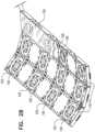
location pad 38 of the magnetic tracking system, orvice versa. Processor 40 insystem 20 is configured to use the electrical signal sensed bysensor 120 to compute a positionP vector and an orientation vectorO ofsensor 120 relative to the origin of the X-Y-Z axes. Position vectorP is the vector from the origin tosensor 120. Orientation vectorO is the axial vector throughcatheter 24. The position of the origin of the X-Y-Z coordinate system shown inFig. 2A is merely for conceptual clarity, and not by way of limitation of the embodiments of the present invention. The origin may be defined in any suitable position relative to the location pad.Fig. 2B is a schematic, pictorial illustration of an alternative embodiment of the location pad, in accordance with an embodiment of the present invention. In this embodiment, eachrow 140 ofcoils 100 is planar, but the rows lie on a slightly curved surface. In this configuration, too, the axes of the magnetic fields generated bycoils 100 are perpendicular to the surface of the location pad. The curved configuration ofFig. 2B is useful, for example, for fitting into the chamber ofMRI scanner 22.- On the right-most row shown in the
Fig. 2B ,magnetic field generators 39 have alid 150 coveringcoils 100, which may be formed from any suitable material, such as a plastic, covering the entire array. - In the configuration of
Fig. 2B , the magnetic fields B generated bycoils 100 are nearly parallel to one another as will be described below. Any small deviations of the magnetic fields B from parallelism due to the curvature shown inFig. 2B were found to have a negligible impact on the accuracy of the catheter position tracking system. - When
location pad 38 is used in a MRI environment, the large magnetic MRI coils generate very large magnetic fields such as in the range of 0.5-3 Tesla. Magnetic catheter tracking systems, such as the CARTO system, use magnets with AC frequencies in the audio frequency range. Hence whenmagnetic coils 100 are driven with the audio frequencies in the presence of the large MRI magnets, smallmagnetic coils 100 can resonate at audio frequencies, e.g., from 19-22 kHz. Thus in some embodiments, the coils are potted in an elastic material, such as silicone or any other suitable material, in order to dampen or otherwise prevent this resonance. For example,trench 105 and any other regions aroundcoil 100 can be filled with silicone, or any other suitable material, which dampen the audio frequency resonances ofcoils 100 inlocation pad 38 in an MRI environment. - Small
magnetic coils 100 can also exhibit large impedances on the order of 600 ohms, e.g., due to skin effects at these frequencies as well as the small size ofcoils 100. These coils are driven with driver amplifier 36, which typically has an output characteristic impedance on the order of 6 ohms. In some embodiments, to drive these high impedance coils, transformers can be used in driver amplifier 36 with an impedance transformation ratio to overcome the impedance mismatches from 6 ohms to 600 ohms. - The array configurations of
Fig. 2A and2B are shown merely for visual clarity and not by way of limitation of the embodiments of the present invention. Any suitable number ofmagnetic coils 100 in any suitable configuration may be used.Coils 100 are not limited to a flat circular shape, but may be of any suitable shape. - As explained above, in the disclosed embodiments the magnetic fields generated by
coils 100 oflocation pad 38 are parallel to one another and perpendicular to the surface of the location pad. As a result, the magnitude of the composite magnetic field varies with the Z coordinate but is substantially constant as a function of X and Y. Therefore, when using a single-axis sensor (e.g.,sensor 120 inFig. 2A ), the magnitude of the composite signal sensed by the sensor is strongly indicative of the height ofdistal end 34 abovelocation pad 38, but is insensitive to the lateral position of the distal tip relative to the location pad. This insensitivity may cause inaccuracy or even lack of conversion in the position and orientation estimation process performed byprocessor 40. - One possible solution for this problem is to use a more complex position sensor in the catheter, such as a three-axis sensor. Such an arrangement is described in U.S. Patent Application Number
US 2007/0265526 , cited above. This solution, however, is complex and increases the catheter diameter. - In some embodiments,
processor 40 estimates the position and orientation ofcatheter 24 is a two-stage process. This process, which is described below, enables the use of a single-axis sensor in conjunction with a low-profile location pad. The disclosed process is computationally-simple and converges quickly and efficiently. Typically, a total of fivecoils 100 is sufficient for providing accurate location, but a larger number of coils (e.g., twelve coils as shown inFigs. 2A and2B ) is preferable for higher accuracy and robustness. - In some embodiments, coils 100 are driven with AC signals having different respective frequencies, so that the signals induced in the single axis sensor coil can be distinguished from one another.
Fig. 3 is a flow chart that schematically illustrates a method for estimating the position ofdistal end 34 ofcatheter 24 relative tolocation pad 38, which may be used with the system of the present invention. In apositioning step 200,location pad 38 is positioned underpatient 32. In an insertingstep 210,catheter 24 is inserted intopatient 32. In a generatingstep 220, coils 100 are driven with respective AC drive signals having different frequencies.- In measuring
step 230,processor 40 measures the electrical voltage signal that is induced incatheter sensor 120 in response to the magnetic field. In afirst estimating step 240,processor 40 estimates an initial Z-distance of the sensor from the location pad by computing the average (e.g., RMS) intensity of the electrical voltage signal (which is proportional to the average magnitude of the composite magnetic field produced by coils 100). - In a
second estimating step 250,processor 40 estimates an initial X-Y position of the sensor relative tolocation pad 38, by analyzing the relative amplitudes of the individual different-frequency components in the induced voltage signal.Processor 40 is able to discriminate among the signal components induced by thedifferent coils 100, because each signal component has a different frequency.Processor 40 may filter the signal sensed bysensor 120 with suitable digital filtering for this purpose. - In an
iterative estimation step 260,processor 40 refines the initial X-Y position estimate fromstep 250 and Z position estimate fromstep 240 of the sensor. Typically,processor 40 carries out an iterative position estimation process that uses the initial X-Y-Z coordinate (output ofsteps 240 and 250) as initial conditions. Due to the relatively-accurate initial conditions, the iterative process converges quickly and reliably to the accurate X-Y-Z coordinate of the catheter distal end. - It will thus be appreciated that the embodiments described above are cited by way of example, and that the present invention is not limited to what has been particularly shown and described hereinabove. Rather, the scope of the present invention is defined by the appended claims and may include both combinations and subcombinations of the various features described hereinabove, as well as variations and modifications thereof which would occur to persons skilled in the art upon reading the foregoing description and which are not disclosed in the prior art.
Claims (12)
- A system (20) for magnetic tracking of an intra-body probe, the system comprising:a location pad (38), an intra-body probe (24), and a control console (26);wherein the location pad comprises:a housing having a flat surface; andat least five field generators (39), which are fixed to the housing and are configured to generate respective magnetic fields having respective axes that are perpendicular to the flat surface such that a magnitude of a composite magnetic field, comprising the superposition of the respective magnetic fields generated by the at least five field generators, is substantially constant as a function of coordinates parallel to the flat surface;wherein the intra-body probe (24) is a tool for inserting into a patient, and comprises a position sensor, the position sensor being capable of generating electrical signals in response to magnetic fields generated by the field generators; andwherein the control console (26) is operatively linkable to the location pad (38) and to the intra-body probe (24), and is adapted to determine a position of the position sensor based on electrical signals received from the position sensor.
- The system according to claim 1, wherein the flat surface lies in a plane.
- The system according to claim 1, wherein the flat surface is curved.
- The system according to claim 1, wherein the housing has a thickness no greater than 5 millimeters.
- The system according to claim 1, wherein the field generators comprise coils (100) having windings that are parallel to the surface.
- The system according to claim 1, wherein the housing comprises elastic material that is configured to hold the field generators and to dampen resonances in the field generators.
- A method for producing a system for magnetic tracking of an intra-body probe, the method comprising:providing a location pad (38), an intra-body probe (24), and a control console (26);wherein providing the location pad comprises:providing a housing having a flat surface; andfixing at least five field generators (39) to the housing, such that the field generators generate respective magnetic fields having respective axes that are perpendicular to the flat surface such that a magnitude of a composite magnetic field, comprising the superposition of the respective magnetic fields generated by the at least five field generators, is substantially constant as a function of coordinates parallel to the flat surface;wherein the intra-body probe (24) is a tool for inserting into a patient, and wherein the providing the intra-body probe comprises:providing a position sensor capable of generating electrical signals in response to magnetic fields generated by the field generators; andwherein the control console (26) is operatively linkable to the location pad (38) and to the intra-body probe (24), and is adapted to determine a position of the provided position sensor based on electrical signals received from the position sensor.
- The method according to claim 7, wherein the flat surface lies in a plane.
- The method according to claim 7, wherein the flat surface is curved.
- The method according to claim 7, wherein the housing has a thickness no greater than 5 millimeters.
- The method according to claim 7, wherein the field generators comprise coils having windings that are parallel to the surface.
- The method according to claim 7, wherein fixing the field generators to the housing comprises holding the field generators in the housing using elastic material, so as to dampen resonances in the field generators.
Applications Claiming Priority (1)
| Application Number | Priority Date | Filing Date | Title |
|---|---|---|---|
| US14/138,654US9474466B2 (en) | 2013-12-23 | 2013-12-23 | Low-profile location pad for magnetic-based intra-body probe tracking system |
Publications (3)
| Publication Number | Publication Date |
|---|---|
| EP2886054A1 EP2886054A1 (en) | 2015-06-24 |
| EP2886054C0 EP2886054C0 (en) | 2024-07-10 |
| EP2886054B1true EP2886054B1 (en) | 2024-07-10 |
Family
ID=52231970
Family Applications (1)
| Application Number | Title | Priority Date | Filing Date |
|---|---|---|---|
| EP14199754.4AActiveEP2886054B1 (en) | 2013-12-23 | 2014-12-22 | Low-profile location pad for magnetic-based intra-body probe tracking system |
Country Status (7)
| Country | Link |
|---|---|
| US (1) | US9474466B2 (en) |
| EP (1) | EP2886054B1 (en) |
| JP (2) | JP6461592B2 (en) |
| CN (2) | CN104720803A (en) |
| AU (2) | AU2014274640B2 (en) |
| CA (1) | CA2875170A1 (en) |
| IL (1) | IL235533B (en) |
Families Citing this family (12)
| Publication number | Priority date | Publication date | Assignee | Title |
|---|---|---|---|---|
| WO2015068069A1 (en) | 2013-11-06 | 2015-05-14 | Mediguide Ltd. | Magnetic field generator with minimal image occlusion and minimal impact on dimensions in c-arm x-ray environments |
| US10966629B2 (en)* | 2014-12-01 | 2021-04-06 | Koninklijke Philips N.V. | Virtually-oriented electromagnetic tracking coil for catheter based navigation |
| US11006853B2 (en)* | 2015-09-04 | 2021-05-18 | Biosense Webster (Israel) Ltd. | Field-based location coordinate correction |
| US11033201B2 (en) | 2015-09-04 | 2021-06-15 | Biosense Webster (Israel) Ltd. | Inconsistent field-based patch location coordinate correction |
| US20170239120A1 (en)* | 2016-02-19 | 2017-08-24 | Covidien Lp | Bed leveling systems for a surgical table |
| JP6931393B2 (en) | 2016-11-21 | 2021-09-01 | セント・ジュード・メディカル・インターナショナル・ホールディング・エスエーアールエルSt. Jude Medical International Holding S.a,r.l. | Perspective transparent magnetic field generator |
| JP6816285B2 (en) | 2016-12-13 | 2021-01-20 | セント・ジュード・メディカル・インターナショナル・ホールディング・エスエーアールエルSt. Jude Medical International Holding S.a,r.l. | Multi-layer flat coil magnetic transmitter |
| US10517612B2 (en) | 2017-09-19 | 2019-12-31 | Biosense Webster (Israel) Ltd. | Nail hole guiding system |
| US10278779B1 (en)* | 2018-06-05 | 2019-05-07 | Elucent Medical, Inc. | Exciter assemblies |
| CN112955074A (en)* | 2018-08-30 | 2021-06-11 | 特瑞格医学有限公司 | Magnetic tracking system for childbirth |
| US11304623B2 (en) | 2018-12-25 | 2022-04-19 | Biosense Webster (Israel) Ltd. | Integration of medical imaging and location tracking |
| US20220036560A1 (en)* | 2020-07-30 | 2022-02-03 | Biosense Webster (Israel) Ltd. | Automatic segmentation of anatomical structures of wide area circumferential ablation points |
Family Cites Families (24)
| Publication number | Priority date | Publication date | Assignee | Title |
|---|---|---|---|---|
| JPH0370106U (en)* | 1989-11-15 | 1991-07-12 | ||
| US5239489A (en)* | 1991-05-06 | 1993-08-24 | International Business Machines Corporation | Pen position and tilt estimators for a digitizer tablet |
| AU1693095A (en)* | 1994-08-19 | 1996-03-14 | Biosense, Inc. | Medical diagnosis, treatment and imaging systems |
| US5729129A (en)* | 1995-06-07 | 1998-03-17 | Biosense, Inc. | Magnetic location system with feedback adjustment of magnetic field generator |
| US7809421B1 (en)* | 2000-07-20 | 2010-10-05 | Biosense, Inc. | Medical system calibration with static metal compensation |
| US6484118B1 (en)* | 2000-07-20 | 2002-11-19 | Biosense, Inc. | Electromagnetic position single axis system |
| US20060241397A1 (en)* | 2005-02-22 | 2006-10-26 | Assaf Govari | Reference pad for position sensing |
| US9295529B2 (en)* | 2005-05-16 | 2016-03-29 | Biosense Webster, Inc. | Position tracking using quasi-DC magnetic fields |
| US7902816B2 (en)* | 2005-12-15 | 2011-03-08 | Koninklijke Philips Electronics N.V. | Electromagnetic tracking method and apparatus for compensation of metal artifacts using modular arrays of reference sensors |
| US20070265526A1 (en)* | 2006-05-11 | 2007-11-15 | Assaf Govari | Low-profile location pad |
| US20070265690A1 (en)* | 2006-05-12 | 2007-11-15 | Yoav Lichtenstein | Position tracking of passive resonance-based transponders |
| US8082020B2 (en)* | 2006-08-07 | 2011-12-20 | Biosense Webster, Inc. | Distortion-immune position tracking using redundant magnetic field measurements |
| EP1944581B1 (en)* | 2007-01-15 | 2011-09-07 | Sony Deutschland GmbH | Distance, orientation and velocity measurement using multi-coil and multi-frequency arrangement |
| US7912662B2 (en) | 2007-09-24 | 2011-03-22 | General Electric Company | System and method for improving the distortion tolerance of an electromagnetic tracking system |
| EP2231008A4 (en)* | 2008-01-08 | 2012-05-02 | Robin Medical Inc | Method and apparatus to estimate location and orientation of objects during magnetic resonance imaging |
| US8504139B2 (en)* | 2009-03-10 | 2013-08-06 | Medtronic Xomed, Inc. | Navigating a surgical instrument |
| DE102011013398A1 (en)* | 2010-03-10 | 2011-09-15 | Northern Digital Inc. | Magnetic location system |
| US9211094B2 (en)* | 2010-12-10 | 2015-12-15 | Biosense Webster (Israel), Ltd. | System and method for detection of metal disturbance based on contact force measurement |
| US8847587B2 (en) | 2011-07-13 | 2014-09-30 | Biosense Webster (Israel) Ltd. | Field generator patch with distortion cancellation |
| US8644917B2 (en) | 2011-09-20 | 2014-02-04 | Albert Einstein Healthcare Network | Cardio mapping system and method for cardio mapping |
| US9173622B2 (en)* | 2011-11-03 | 2015-11-03 | Creative Ultrasound Imaging, Inc. | Elevating and rotating ultrasound patient stand |
| JP5836760B2 (en)* | 2011-11-04 | 2015-12-24 | キヤノン株式会社 | Acoustic wave acquisition apparatus and acoustic wave acquisition method |
| NL2009885C2 (en)* | 2011-11-30 | 2014-12-09 | Gen Electric | System and method for automated landmarking. |
| EP2827935B1 (en) | 2012-03-18 | 2018-01-10 | Traumatek Solutions B.V. | Devices for endovascular access and therapy |
- 2013
- 2013-12-23USUS14/138,654patent/US9474466B2/enactiveActive
- 2014
- 2014-11-06ILIL235533Apatent/IL235533B/enactiveIP Right Grant
- 2014-12-12AUAU2014274640Apatent/AU2014274640B2/ennot_activeCeased
- 2014-12-15CACA2875170Apatent/CA2875170A1/ennot_activeAbandoned
- 2014-12-22JPJP2014258372Apatent/JP6461592B2/enactiveActive
- 2014-12-22EPEP14199754.4Apatent/EP2886054B1/enactiveActive
- 2014-12-23CNCN201410815219.7Apatent/CN104720803A/enactivePending
- 2014-12-23CNCN202111093027.6Apatent/CN113768489A/enactivePending
- 2018
- 2018-12-21JPJP2018239320Apatent/JP6710747B2/enactiveActive
- 2019
- 2019-03-20AUAU2019201943Apatent/AU2019201943A1/ennot_activeAbandoned
Also Published As
| Publication number | Publication date |
|---|---|
| EP2886054C0 (en) | 2024-07-10 |
| EP2886054A1 (en) | 2015-06-24 |
| JP2019080934A (en) | 2019-05-30 |
| JP6461592B2 (en) | 2019-01-30 |
| CN113768489A (en) | 2021-12-10 |
| AU2019201943A1 (en) | 2019-04-11 |
| JP2015119971A (en) | 2015-07-02 |
| CA2875170A1 (en) | 2015-06-23 |
| IL235533B (en) | 2018-01-31 |
| AU2014274640B2 (en) | 2019-03-07 |
| AU2014274640A1 (en) | 2015-07-09 |
| JP6710747B2 (en) | 2020-06-17 |
| US20150173643A1 (en) | 2015-06-25 |
| US9474466B2 (en) | 2016-10-25 |
| CN104720803A (en) | 2015-06-24 |
| IL235533A0 (en) | 2015-02-26 |
Similar Documents
| Publication | Publication Date | Title |
|---|---|---|
| EP2886054B1 (en) | Low-profile location pad for magnetic-based intra-body probe tracking system | |
| JP6679786B2 (en) | Calibration jig and calibration method for flat locating pads | |
| EP3914182B1 (en) | Flexible multi-coil tracking sensor | |
| US7650178B2 (en) | Magnetic field sensor-based navigation system to track MR image-guided interventional procedures | |
| EP0722290B1 (en) | Magnetic determination of position and orientation | |
| EP2005208B1 (en) | System for local error compensation in electromagnetic tracking systems | |
| US20130317334A1 (en) | Position sensing using electric dipole fields | |
| AU2013206488A1 (en) | Catheter with synthetic aperture mri sensor | |
| US11234769B2 (en) | Wireless electromagnetic navigational element | |
| WO2019126418A1 (en) | Medical device location and tracking system | |
| HK1099580A (en) | Magnetic determination of position and orientation |
Legal Events
| Date | Code | Title | Description |
|---|---|---|---|
| PUAI | Public reference made under article 153(3) epc to a published international application that has entered the european phase | Free format text:ORIGINAL CODE: 0009012 | |
| 17P | Request for examination filed | Effective date:20141222 | |
| AK | Designated contracting states | Kind code of ref document:A1 Designated state(s):AL AT BE BG CH CY CZ DE DK EE ES FI FR GB GR HR HU IE IS IT LI LT LU LV MC MK MT NL NO PL PT RO RS SE SI SK SM TR | |
| AX | Request for extension of the european patent | Extension state:BA ME | |
| R17P | Request for examination filed (corrected) | Effective date:20160104 | |
| RBV | Designated contracting states (corrected) | Designated state(s):AL AT BE BG CH CY CZ DE DK EE ES FI FR GB GR HR HU IE IS IT LI LT LU LV MC MK MT NL NO PL PT RO RS SE SI SK SM TR | |
| STAA | Information on the status of an ep patent application or granted ep patent | Free format text:STATUS: EXAMINATION IS IN PROGRESS | |
| 17Q | First examination report despatched | Effective date:20200421 | |
| RAP3 | Party data changed (applicant data changed or rights of an application transferred) | Owner name:BIOSENSE WEBSTER (ISRAEL) LTD. | |
| GRAP | Despatch of communication of intention to grant a patent | Free format text:ORIGINAL CODE: EPIDOSNIGR1 | |
| STAA | Information on the status of an ep patent application or granted ep patent | Free format text:STATUS: GRANT OF PATENT IS INTENDED | |
| INTG | Intention to grant announced | Effective date:20240103 | |
| GRAJ | Information related to disapproval of communication of intention to grant by the applicant or resumption of examination proceedings by the epo deleted | Free format text:ORIGINAL CODE: EPIDOSDIGR1 | |
| STAA | Information on the status of an ep patent application or granted ep patent | Free format text:STATUS: EXAMINATION IS IN PROGRESS | |
| GRAP | Despatch of communication of intention to grant a patent | Free format text:ORIGINAL CODE: EPIDOSNIGR1 | |
| STAA | Information on the status of an ep patent application or granted ep patent | Free format text:STATUS: GRANT OF PATENT IS INTENDED | |
| INTC | Intention to grant announced (deleted) | ||
| INTG | Intention to grant announced | Effective date:20240423 | |
| GRAS | Grant fee paid | Free format text:ORIGINAL CODE: EPIDOSNIGR3 | |
| GRAA | (expected) grant | Free format text:ORIGINAL CODE: 0009210 | |
| STAA | Information on the status of an ep patent application or granted ep patent | Free format text:STATUS: THE PATENT HAS BEEN GRANTED | |
| AK | Designated contracting states | Kind code of ref document:B1 Designated state(s):AL AT BE BG CH CY CZ DE DK EE ES FI FR GB GR HR HU IE IS IT LI LT LU LV MC MK MT NL NO PL PT RO RS SE SI SK SM TR | |
| REG | Reference to a national code | Ref country code:CH Ref legal event code:EP | |
| REG | Reference to a national code | Ref country code:DE Ref legal event code:R096 Ref document number:602014090473 Country of ref document:DE | |
| U01 | Request for unitary effect filed | Effective date:20240724 | |
| U07 | Unitary effect registered | Designated state(s):AT BE BG DE DK EE FI FR IT LT LU LV MT NL PT RO SE SI Effective date:20240902 | |
| U20 | Renewal fee for the european patent with unitary effect paid | Year of fee payment:11 Effective date:20241107 | |
| PG25 | Lapsed in a contracting state [announced via postgrant information from national office to epo] | Ref country code:NO Free format text:LAPSE BECAUSE OF FAILURE TO SUBMIT A TRANSLATION OF THE DESCRIPTION OR TO PAY THE FEE WITHIN THE PRESCRIBED TIME-LIMIT Effective date:20241010 | |
| PG25 | Lapsed in a contracting state [announced via postgrant information from national office to epo] | Ref country code:PL Free format text:LAPSE BECAUSE OF FAILURE TO SUBMIT A TRANSLATION OF THE DESCRIPTION OR TO PAY THE FEE WITHIN THE PRESCRIBED TIME-LIMIT Effective date:20240710 Ref country code:GR Free format text:LAPSE BECAUSE OF FAILURE TO SUBMIT A TRANSLATION OF THE DESCRIPTION OR TO PAY THE FEE WITHIN THE PRESCRIBED TIME-LIMIT Effective date:20241011 | |
| PGFP | Annual fee paid to national office [announced via postgrant information from national office to epo] | Ref country code:GB Payment date:20241031 Year of fee payment:11 | |
| PG25 | Lapsed in a contracting state [announced via postgrant information from national office to epo] | Ref country code:IS Free format text:LAPSE BECAUSE OF FAILURE TO SUBMIT A TRANSLATION OF THE DESCRIPTION OR TO PAY THE FEE WITHIN THE PRESCRIBED TIME-LIMIT Effective date:20241110 | |
| PG25 | Lapsed in a contracting state [announced via postgrant information from national office to epo] | Ref country code:HR Free format text:LAPSE BECAUSE OF FAILURE TO SUBMIT A TRANSLATION OF THE DESCRIPTION OR TO PAY THE FEE WITHIN THE PRESCRIBED TIME-LIMIT Effective date:20240710 | |
| PG25 | Lapsed in a contracting state [announced via postgrant information from national office to epo] | Ref country code:ES Free format text:LAPSE BECAUSE OF FAILURE TO SUBMIT A TRANSLATION OF THE DESCRIPTION OR TO PAY THE FEE WITHIN THE PRESCRIBED TIME-LIMIT Effective date:20240710 Ref country code:RS Free format text:LAPSE BECAUSE OF FAILURE TO SUBMIT A TRANSLATION OF THE DESCRIPTION OR TO PAY THE FEE WITHIN THE PRESCRIBED TIME-LIMIT Effective date:20241010 | |
| PG25 | Lapsed in a contracting state [announced via postgrant information from national office to epo] | Ref country code:RS Free format text:LAPSE BECAUSE OF FAILURE TO SUBMIT A TRANSLATION OF THE DESCRIPTION OR TO PAY THE FEE WITHIN THE PRESCRIBED TIME-LIMIT Effective date:20241010 Ref country code:PL Free format text:LAPSE BECAUSE OF FAILURE TO SUBMIT A TRANSLATION OF THE DESCRIPTION OR TO PAY THE FEE WITHIN THE PRESCRIBED TIME-LIMIT Effective date:20240710 Ref country code:NO Free format text:LAPSE BECAUSE OF FAILURE TO SUBMIT A TRANSLATION OF THE DESCRIPTION OR TO PAY THE FEE WITHIN THE PRESCRIBED TIME-LIMIT Effective date:20241010 Ref country code:IS Free format text:LAPSE BECAUSE OF FAILURE TO SUBMIT A TRANSLATION OF THE DESCRIPTION OR TO PAY THE FEE WITHIN THE PRESCRIBED TIME-LIMIT Effective date:20241110 Ref country code:HR Free format text:LAPSE BECAUSE OF FAILURE TO SUBMIT A TRANSLATION OF THE DESCRIPTION OR TO PAY THE FEE WITHIN THE PRESCRIBED TIME-LIMIT Effective date:20240710 Ref country code:GR Free format text:LAPSE BECAUSE OF FAILURE TO SUBMIT A TRANSLATION OF THE DESCRIPTION OR TO PAY THE FEE WITHIN THE PRESCRIBED TIME-LIMIT Effective date:20241011 Ref country code:ES Free format text:LAPSE BECAUSE OF FAILURE TO SUBMIT A TRANSLATION OF THE DESCRIPTION OR TO PAY THE FEE WITHIN THE PRESCRIBED TIME-LIMIT Effective date:20240710 | |
| PG25 | Lapsed in a contracting state [announced via postgrant information from national office to epo] | Ref country code:SM Free format text:LAPSE BECAUSE OF FAILURE TO SUBMIT A TRANSLATION OF THE DESCRIPTION OR TO PAY THE FEE WITHIN THE PRESCRIBED TIME-LIMIT Effective date:20240710 | |
| PG25 | Lapsed in a contracting state [announced via postgrant information from national office to epo] | Ref country code:CZ Free format text:LAPSE BECAUSE OF FAILURE TO SUBMIT A TRANSLATION OF THE DESCRIPTION OR TO PAY THE FEE WITHIN THE PRESCRIBED TIME-LIMIT Effective date:20240710 | |
| PG25 | Lapsed in a contracting state [announced via postgrant information from national office to epo] | Ref country code:SK Free format text:LAPSE BECAUSE OF FAILURE TO SUBMIT A TRANSLATION OF THE DESCRIPTION OR TO PAY THE FEE WITHIN THE PRESCRIBED TIME-LIMIT Effective date:20240710 | |
| PLBE | No opposition filed within time limit | Free format text:ORIGINAL CODE: 0009261 | |
| STAA | Information on the status of an ep patent application or granted ep patent | Free format text:STATUS: NO OPPOSITION FILED WITHIN TIME LIMIT | |
| 26N | No opposition filed | Effective date:20250411 | |
| PG25 | Lapsed in a contracting state [announced via postgrant information from national office to epo] | Ref country code:MC Free format text:LAPSE BECAUSE OF FAILURE TO SUBMIT A TRANSLATION OF THE DESCRIPTION OR TO PAY THE FEE WITHIN THE PRESCRIBED TIME-LIMIT Effective date:20240710 | |
| REG | Reference to a national code | Ref country code:CH Ref legal event code:PL |