EP2886026B1 - Combined heating and stirring arrangement method for heating food and heating stirrer - Google Patents
Combined heating and stirring arrangement method for heating food and heating stirrerDownload PDFInfo
- Publication number
- EP2886026B1 EP2886026B1EP13198714.1AEP13198714AEP2886026B1EP 2886026 B1EP2886026 B1EP 2886026B1EP 13198714 AEP13198714 AEP 13198714AEP 2886026 B1EP2886026 B1EP 2886026B1
- Authority
- EP
- European Patent Office
- Prior art keywords
- heating
- magnetic
- arrangement
- stirring device
- stirring
- Prior art date
- Legal status (The legal status is an assumption and is not a legal conclusion. Google has not performed a legal analysis and makes no representation as to the accuracy of the status listed.)
- Active
Links
- 238000003756stirringMethods0.000titleclaimsdescription104
- 238000010438heat treatmentMethods0.000titleclaimsdescription52
- 235000013305foodNutrition0.000titleclaimsdescription24
- 238000000034methodMethods0.000titleclaimsdescription12
- 230000005291magnetic effectEffects0.000claimsdescription74
- 238000010411cookingMethods0.000claimsdescription47
- 230000007246mechanismEffects0.000claimsdescription17
- 230000006698inductionEffects0.000claimsdescription14
- 239000000126substanceSubstances0.000claimsdescription14
- 229910000859α-FeInorganic materials0.000claimsdescription14
- 230000005294ferromagnetic effectEffects0.000claimsdescription12
- 230000005284excitationEffects0.000claimsdescription6
- 239000004020conductorSubstances0.000claims1
- 238000011161developmentMethods0.000description11
- 230000018109developmental processEffects0.000description11
- 230000008569processEffects0.000description7
- 238000002360preparation methodMethods0.000description5
- 230000004907fluxEffects0.000description4
- 238000003760magnetic stirringMethods0.000description4
- 239000000463materialSubstances0.000description4
- 239000012530fluidSubstances0.000description3
- 230000001939inductive effectEffects0.000description3
- 238000009826distributionMethods0.000description2
- 230000001976improved effectEffects0.000description2
- 239000007788liquidSubstances0.000description2
- 238000004519manufacturing processMethods0.000description2
- 235000012054mealsNutrition0.000description2
- 238000004804windingMethods0.000description2
- 229920000297RayonPolymers0.000description1
- 229910000831SteelInorganic materials0.000description1
- 230000003213activating effectEffects0.000description1
- 230000004913activationEffects0.000description1
- 230000009286beneficial effectEffects0.000description1
- 238000004364calculation methodMethods0.000description1
- DGLFSNZWRYADFC-UHFFFAOYSA-Nchembl2334586Chemical compoundC1CCC2=CN=C(N)N=C2C2=C1NC1=CC=C(C#CC(C)(O)C)C=C12DGLFSNZWRYADFC-UHFFFAOYSA-N0.000description1
- 238000002485combustion reactionMethods0.000description1
- 230000008094contradictory effectEffects0.000description1
- 230000008878couplingEffects0.000description1
- 238000010168coupling processMethods0.000description1
- 238000005859coupling reactionMethods0.000description1
- 238000005520cutting processMethods0.000description1
- 230000001419dependent effectEffects0.000description1
- 238000013461designMethods0.000description1
- 230000000694effectsEffects0.000description1
- 238000005265energy consumptionMethods0.000description1
- 238000005516engineering processMethods0.000description1
- 238000002474experimental methodMethods0.000description1
- 238000007667floatingMethods0.000description1
- 238000005259measurementMethods0.000description1
- 238000002156mixingMethods0.000description1
- 230000001737promoting effectEffects0.000description1
- 235000011962puddingsNutrition0.000description1
- 238000009877renderingMethods0.000description1
- 230000000630rising effectEffects0.000description1
- 235000015067saucesNutrition0.000description1
- 239000010959steelSubstances0.000description1
- 238000003860storageMethods0.000description1
- 230000008093supporting effectEffects0.000description1
- 235000019640tasteNutrition0.000description1
- 238000012546transferMethods0.000description1
Images


Classifications
- A—HUMAN NECESSITIES
- A47—FURNITURE; DOMESTIC ARTICLES OR APPLIANCES; COFFEE MILLS; SPICE MILLS; SUCTION CLEANERS IN GENERAL
- A47J—KITCHEN EQUIPMENT; COFFEE MILLS; SPICE MILLS; APPARATUS FOR MAKING BEVERAGES
- A47J43/00—Implements for preparing or holding food, not provided for in other groups of this subclass
- A47J43/04—Machines for domestic use not covered elsewhere, e.g. for grinding, mixing, stirring, kneading, emulsifying, whipping or beating foodstuffs, e.g. power-driven
- A47J43/046—Machines for domestic use not covered elsewhere, e.g. for grinding, mixing, stirring, kneading, emulsifying, whipping or beating foodstuffs, e.g. power-driven with tools driven from the bottom side
- A47J43/0465—Machines for domestic use not covered elsewhere, e.g. for grinding, mixing, stirring, kneading, emulsifying, whipping or beating foodstuffs, e.g. power-driven with tools driven from the bottom side with magnetic drive
- A—HUMAN NECESSITIES
- A23—FOODS OR FOODSTUFFS; TREATMENT THEREOF, NOT COVERED BY OTHER CLASSES
- A23L—FOODS, FOODSTUFFS OR NON-ALCOHOLIC BEVERAGES, NOT OTHERWISE PROVIDED FOR; PREPARATION OR TREATMENT THEREOF
- A23L5/00—Preparation or treatment of foods or foodstuffs, in general; Food or foodstuffs obtained thereby; Materials therefor
- A23L5/10—General methods of cooking foods, e.g. by roasting or frying
- A23L5/15—General methods of cooking foods, e.g. by roasting or frying using wave energy, irradiation, electrical means or magnetic fields, e.g. oven cooking or roasting using radiant dry heat
- A—HUMAN NECESSITIES
- A47—FURNITURE; DOMESTIC ARTICLES OR APPLIANCES; COFFEE MILLS; SPICE MILLS; SUCTION CLEANERS IN GENERAL
- A47J—KITCHEN EQUIPMENT; COFFEE MILLS; SPICE MILLS; APPARATUS FOR MAKING BEVERAGES
- A47J27/00—Cooking-vessels
- A47J27/004—Cooking-vessels with integral electrical heating means
- B—PERFORMING OPERATIONS; TRANSPORTING
- B01—PHYSICAL OR CHEMICAL PROCESSES OR APPARATUS IN GENERAL
- B01F—MIXING, e.g. DISSOLVING, EMULSIFYING OR DISPERSING
- B01F33/00—Other mixers; Mixing plants; Combinations of mixers
- B01F33/45—Magnetic mixers; Mixers with magnetically driven stirrers
- B01F33/452—Magnetic mixers; Mixers with magnetically driven stirrers using independent floating stirring elements
- B—PERFORMING OPERATIONS; TRANSPORTING
- B01—PHYSICAL OR CHEMICAL PROCESSES OR APPARATUS IN GENERAL
- B01F—MIXING, e.g. DISSOLVING, EMULSIFYING OR DISPERSING
- B01F33/00—Other mixers; Mixing plants; Combinations of mixers
- B01F33/45—Magnetic mixers; Mixers with magnetically driven stirrers
- B01F33/453—Magnetic mixers; Mixers with magnetically driven stirrers using supported or suspended stirring elements
- A—HUMAN NECESSITIES
- A23—FOODS OR FOODSTUFFS; TREATMENT THEREOF, NOT COVERED BY OTHER CLASSES
- A23V—INDEXING SCHEME RELATING TO FOODS, FOODSTUFFS OR NON-ALCOHOLIC BEVERAGES AND LACTIC OR PROPIONIC ACID BACTERIA USED IN FOODSTUFFS OR FOOD PREPARATION
- A23V2002/00—Food compositions, function of food ingredients or processes for food or foodstuffs
Definitions
- German patent publication document DE 10 2006 052475 A1discloses an automatic stirring device in a kitchen hob.
- a magnetic stirring elementis propelled by a magnetic engine integrated in the cooking plate.
- the cooking surface material of the hobis required to have thermal conductivity in order to enable heat transfer from a heating device into a cooking vessel, which contains the magnetic stirrer.
- heat sourcesgas combustion and electrical energy as well as induction heating are disclosed as potential alternatives.
- Document DE917996 Cdiscusses a mixer where the cutting tool can be heated.
- the cutting- / mixing toolis electrically driven.
- the inventionis based on the problem to provide a reliable stirrer in the presence of induction heating, especially for a kitchen hob.
- the applicanthas conducted experiments with magnetic stirrers and induction heating and has found that it is difficult to be provided in the presence of ferromagnetic cooking vessels.
- the combined heating and stirring arrangementcombines a stirring device having magnetic and electrical properties as well as a propelling mechanism to magnetically propel the stirring device and a heating mechanism to heat the stirring device.
- a ferromagnetic cooking vesselcan be omitted while at the same time presenting a simple heating and stirring arrangement that allows sophisticated control over the cooking process.
- the heating mechanismis based on magnetic induction, as in this manner the food can be heated in an energy-efficient and highly controllable manner, while at the same time promoting the focusing of the heating energy inside of the cooking vessel and allowing to keep it there.
- the electrical energy for cookingis optimally used.
- an embodiment of an arrangement according to the present inventionfurther comprises a non-conductive/non-ferromagnetic cooking vessel, because such a cooking vessel does not impede the magnetic waves on their way to a stirring device and allows a controllable and homogeneous distribution of the magnetic field in any desired manner inside of the cooking vessel.
- the propelling mechanismis based on magnetic attraction and repulsion.
- Such a solutionprovides a highly controllable stirring of stirring devices in various shapes in a beneficial manner.
- itcomprises a guide for the magnetic field lines, thus focusing the magnetic energy leading to a higher efficiency of the magnetic propelling mechanism.
- the guide of the magnetic field linesis made of ferrite material, which is highly suitable for guiding magnetic field lines and thus leads to a high efficiency of the magnetic propelling mechanism.
- a plurality of magnetic coilsare provided adapted to be energized by a time schedule in sequence.
- a propelling mechanismcan be provided without moving parts that takes any actual position of the stirring device into account and at the same time repels it and attracts it with an appropriately controlled coil arrangement.
- the stirring speed as well as the stirring power / momentcan be exactly controlled.
- a number of magnetic polesis adapted to the number of excitation phases of the electrical current.
- the magnetic propelling mechanismcan be optimally adapted to the electrical supply situation, be it either present in one phase or three phases, as commonly available.
- the number of magnetic coilsis adapted to the number of excitation phases because in such a manner, the magnetic propelling mechanism can be efficiently operated in the presence of different electrical supply situations.
- the heating mechanism and the propelling mechanismare combined.
- fewer partsare required to build the arrangement.
- the reliability of the arrangementcan be improved and a manufacturing of the arrangement can be simplified.
- the stirring devicecan be adapted to a cooking situation and provided in different shapes, which also allows further control of the rotation speed and the cooking result in the presence of different food dishes and electrical supply situations.
- the stirring deviceis shaped to promote turbulence when moved inside the substance to be stirred, In this manner, an optimum stirring and heating result can be promoted.
- a non-conductive /ferromagnetic cooking vesselcooking and stirring is effected by a magnetic field.
- Magnetic field- and induction technologyis available on a sophisticated level and thus allows a fine tuning of the cooking process in terms of energy use and controllability of the stirring speed as well as the heating capacity.
- the stirring device according to the present inventionis electrically conductive and has at least two magnetic poles. This facilitates propulsion by a magnetic field as well as heating by an inductive field in an efficient manner in one single component.
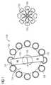
- a preferred embodiment of a cooking arrangement 100comprises a stirring device 120 which consists of a magnet 124 having a north pole and a magnet 122 having a south pole. Also shown are several coils 125 and 128 suitable for the generation of a rotating magnetic field. Further shown is another coil 110 for generating an inductive field that e.g. serves the heating of a stirring device 120. By appropriately switching the coils, e.g. 125 and 128, the stirring device 120 can be propelled in a manner that one coil attracts a pole and another coil rejects a pole of the stirring device. By switching the coils in a rotating manner and in a time schedule, the speed and the force effected by the stirring device 120 can be controlled.
- the stirring device 150has plural poles 150 with only north pole 160 and south pole 155 pointed out and marked here. It may be used in the presence of plural excitation phases.
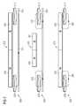
- FIG. 2shows, various magnetic coil arrangements are possible.
- coils 220, 210cooperate to propel a stirring device 205 which has a north pole 202 and a south pole 207.
- a ferrite bar 230is present that guides the magnetic field lines 225 throughout the coil and throughout the stirring device 205. In this manner, an efficient magnetic propelling can be achieved.
- the length of the stirring deviceplays a role. Once the magnetic field lines do not enter the stirring device, the propelling of it is not possible.
- Such an example 240is for instance given below.
- a shorter magnetic stirring device 245is shown that has a magnetic north pole 242 and a magnetic south pole 247.
- this stirring device 245should be propelled by a coil 210 cooperating with another coil 220 that are also connected by a ferrite bar 230.
- Any other configuration of ferrite guidecan also be conceived by the person skilled in the art.
- it can be clearly recognized that the magnetic field lines 255 of the coil 220 and 257 of the coil 210do not enter the stirring device 245, and thus it cannot be propelled in such an arrangement.
- this formulais approximated is however important in order to understand the attenuation of the magnetic field with increasing distance.
- dB/dr0 for a known distance x.
- a total force per pole for one coilcan be calculated in order to be able to create a rotation and an attraction in a direction of the vessel bottom.
- the whole forceis creating the moment, and the stirring device has a length of 20 cm.
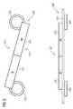
- Fig. 3shows another example of the combined heating stirring arrangement according to an embodiment of the present invention.
- a stirring device 310has a magnetic south pole 122 and a magnetic north pole 124 and is propelled by a coil 330 cooperating with the coil 320.
- the coilsemanate a magnetic field throughout the bottom of a non-conducting/non-ferromagnetic vessel 350.
- the stirring device 120rests on the bottom of the vessel, it can be easily conceived that in the presence of a fluid the friction between the bottom of the vessel and the stirring device 120 can be overcome due to the liquid film between the stirring device and the bottom of the cooking vessel 350.
- the mobility of the stirring device in the cooking vesselcan be further improved by providing it with small protrusions in order to minimize the contact surface between the bottom of the cooking vessel and the stirring device 120.
- the stirring devicecan be equipped with an optimized shape in order to improve its floating capabilities and its stirring capabilities in a sense of creating turbulence in the substance to be heated and stirred.
- an experimental setupcomprises a stirring device 420, a coil 330, the bottom of a cooking vessel 350 and a gauge 440.
- the coilapproximately measures 15 mm in length, whereas the windings are spread over 10 mm over the coil core, whereas the distance between the coil core and the magnetic stirring device is about 5 mm and the thickness of the bottom of the cooking vessel is about 4 mm. It can be conceived that these measurements depend on the size of the coils, the amount of energy needed for heating and the amount of food needed to be heated as well as the moment that needs to be created for stirring the food to be heated and thus are variables.
- the combined heating stirring arrangementcan comprise e.g. 18 magnetic coils 530, 540 and a number of six magnets having a south pole 522 and a north pole 524 arranged outside of a ferromagnetic disk which in this case is equipped with protrusions in the shape of fins, in order to create turbulence in the fluid which is stirred and heated by the combined heating and stirring device. Also shown is that a torsional moment 130 is created by this stirring device.
- the stirring device according to this embodiment 520is propelled by activating the magnetic coils 530, 540 - only two of these coils are indicated with reference signs, but the person skilled in the art understands that all of the coils are used in the magnetic propelling process - in a timely scheduled manner, one after another depending on the desired speed of the stirring device 120 and a torsional moment that is required to stir the fluid respectively the substance or food to be heated.
- the magnets 522, 524are grouped on three axes in pole pairs such that three pole pairs in a distance of respectively 60° are present. More or less pole pairs can be desirable depending on the application case and further experimental cooking results.
- Embodiments of the present inventionprovide different alternatives.
- the rotating field and the field for heatingare e.g. split.
- the coils used for creating and rotatingare e.g. used in parallel to heat up the stirring device. In this case, however, it has to be considered that contradictory requirements are to be satisfied by such an arrangement.
- An exemplary propelling arrangementmay consist in 18 coils which correspond to a number of pole pairs of three phase excitations. Six coils may be switched in sequence at a time which leads to three phases.
- the coil diametermay be preferably 3 cm.
- the inner part of the stirring devicemay consist of a structured piece of ferromagnetic steel. This should be heated up by the inductive field. On the other hand, it should also be able to serve the purpose to conduct the magnetic field from the single poles to each other. Further, it should be beneficially shaped in order to be suitable for stirring food. In this case, an induction coil with a diameter of 14 cm might be used which would lead to a limitation of a maximum power. Generally, by using a greater number of coils, a bigger force can be created. On the other hand, under the different coils that are creating a magnetic field for propelling the stirring device, a ring of ferrites may be favorably provided. Further, it should be considered that all the material constants are also depending on a temperature, so that appropriate material can be selected for a particular cooking case. Such parameters are, for instance, the resistance R and the inductance L.
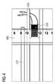
- a combined heating stirring arrangementmay be implemented in an induction cooking hob.
- a cooking vessel 650is shown that contains a stirring device 610 suitable to stir a food substance 640.
- the stirring device 610has at least a south pole 622 and a north pole 624.
- a ferrite element 690is provided in order to guide the magnetic field lines.
- the figureshows coils 620 and 630 which are adapted to propel the stirring device 610.
- a cooking top surface 655is shown which is preferably non-thermally conducting in order to keep the thermal energy inside of the cooking vessel 650.
- a coil 670which serves the purpose of heating the stirring device 610 by means of magnetic induction.
- a control 660is shown, which may be used to control the time sequence of the activation of the coils 620 and 630 as well as the power emanated by the induction coil 670.
- the control 660may operate according to an automated cooking program that prepares the food 670 according to a certain recipe meaning, a certain stirring speed and a certain heating according to a time schedule depending on the food and the desired condition of the food after its preparation.
Landscapes
- Engineering & Computer Science (AREA)
- Food Science & Technology (AREA)
- Chemical & Material Sciences (AREA)
- Mechanical Engineering (AREA)
- Health & Medical Sciences (AREA)
- Nutrition Science (AREA)
- Life Sciences & Earth Sciences (AREA)
- Polymers & Plastics (AREA)
- Chemical Kinetics & Catalysis (AREA)
- Induction Heating Cooking Devices (AREA)
- Cookers (AREA)
- General Induction Heating (AREA)
Description
- Due to more and more obligations in modern times, saving time is becoming more and more important. In today's household environments, this means that the tendency to automate household appliances as much as possible is to be observed. On the other hand, the expectations of potential customers regarding the performance, the design, the energy consumption and the reliability of the devices are rising.
- In the field of food preparation in kitchen environments, many people wish to be their own chef and prepare food with various tastes on a sophisticated level. In this area, the preparation of liquid dishes with low viscosity poses a high risk that while they are heated to burn them at the bottom of the cooking vessel. Therefore, in the past, people were required to focus their attention particularly on such meals and to constantly observe the cooking process by stirring the food while heating it. If the cook would not need to observe one dish constantly, he could focus on other related tasks or the preparation of other courses of the meal.
- Thus, there is a requirement to facilitate the cooking of viscose substances and to relieve a cook from the duty of constantly stirring such dishes as sauces, puddings, risotto or the like.
- Further, there is also a tendency to reduce the complexity of household appliances, such as kitchen hobs, and to minimize the number of components that are used in order to speed up the manufacturing process and reduce storage and transport complexity. The German patent
publication document DE 10 2006 052475 A1 discloses an automatic stirring device in a kitchen hob. A magnetic stirring element is propelled by a magnetic engine integrated in the cooking plate. The cooking surface material of the hob is required to have thermal conductivity in order to enable heat transfer from a heating device into a cooking vessel, which contains the magnetic stirrer. As heat sources, gas combustion and electrical energy as well as induction heating are disclosed as potential alternatives. - However, no teaching is given as to how the various combinations of heat sources with a magnetic stirrer are to be operated in practical use.
- Document
DE917996 C discusses a mixer where the cutting tool can be heated. The cutting- / mixing tool is electrically driven. - In document
US5834739 A a stirring hot plate having an electrical heating element embedded in a generally horizontal plate for supporting a vessel containing a substance to be selectively heated and stirred is disclosed. A stirring device drive and control are mounted in a low temperature enclosure. The stirring device is propelled by a moving magnet. - The invention is based on the problem to provide a reliable stirrer in the presence of induction heating, especially for a kitchen hob.
- This problem is solved by a combined heating and stirring arrangement according to
claim 1, a method for heating food according toclaim 13 and a heating stirred according to claim 15. - Further developments of the invention are given in the dependent claims.
- The applicant has conducted experiments with magnetic stirrers and induction heating and has found that it is difficult to be provided in the presence of ferromagnetic cooking vessels.
- Further, it is also found advantageous to operate induction hobs with nun-thermally conducting cooking top surfaces, as a thermally conducting cooking surface draws thermal energy out of the cooking vessel, which is focused there by induction heating, and thus costs energy and time rendering the cooking process inefficient.
- Advantageously, the combined heating and stirring arrangement according to the present invention combines a stirring device having magnetic and electrical properties as well as a propelling mechanism to magnetically propel the stirring device and a heating mechanism to heat the stirring device. In this manner, a ferromagnetic cooking vessel can be omitted while at the same time presenting a simple heating and stirring arrangement that allows sophisticated control over the cooking process, Beneficially, according to the arrangement according to the present invention, the heating mechanism is based on magnetic induction, as in this manner the food can be heated in an energy-efficient and highly controllable manner, while at the same time promoting the focusing of the heating energy inside of the cooking vessel and allowing to keep it there. Thus, only the food is heated and the electrical energy for cooking is optimally used.
- Beneficially, according to a further development of an embodiment of an arrangement according to the present invention, it further comprises a non-conductive/non-ferromagnetic cooking vessel, because such a cooking vessel does not impede the magnetic waves on their way to a stirring device and allows a controllable and homogeneous distribution of the magnetic field in any desired manner inside of the cooking vessel.
- In an advantageous manner, according to a further development of an embodiment of the arrangement according to the present invention, the propelling mechanism is based on magnetic attraction and repulsion. Such a solution provides a highly controllable stirring of stirring devices in various shapes in a beneficial manner.
- Favorably, according to a further development of an embodiment of the arrangement according to the present invention, it comprises a guide for the magnetic field lines, thus focusing the magnetic energy leading to a higher efficiency of the magnetic propelling mechanism.
- Beneficially, according to a further development of an embodiment of the arrangement of the present invention, the guide of the magnetic field lines is made of ferrite material, which is highly suitable for guiding magnetic field lines and thus leads to a high efficiency of the magnetic propelling mechanism.
- Advantageously, according to a further development of an embodiment of the arrangement according to the present invention, a plurality of magnetic coils are provided adapted to be energized by a time schedule in sequence. In this manner, efficiently, a propelling mechanism can be provided without moving parts that takes any actual position of the stirring device into account and at the same time repels it and attracts it with an appropriately controlled coil arrangement. In this manner, the stirring speed as well as the stirring power / moment can be exactly controlled.
- Advantageously, according to a further development of an embodiment of the arrangement according to the present invention, a number of magnetic poles is adapted to the number of excitation phases of the electrical current. In this manner, the magnetic propelling mechanism can be optimally adapted to the electrical supply situation, be it either present in one phase or three phases, as commonly available.
- Beneficially, according to a further development of an embodiment of an arrangement according to the present invention, the number of magnetic coils is adapted to the number of excitation phases because in such a manner, the magnetic propelling mechanism can be efficiently operated in the presence of different electrical supply situations.
- Advantageously, in a further development of an arrangement according to the present invention, the heating mechanism and the propelling mechanism are combined. In this manner, fewer parts are required to build the arrangement. Thus, the reliability of the arrangement can be improved and a manufacturing of the arrangement can be simplified.
- Advantageously, in a further development of an arrangement of an embodiment according to the present invention, the stirring device can be adapted to a cooking situation and provided in different shapes, which also allows further control of the rotation speed and the cooking result in the presence of different food dishes and electrical supply situations.
- Advantageously, according to a further development of an embodiment of the arrangement according to the present invention, the stirring device is shaped to promote turbulence when moved inside the substance to be stirred, In this manner, an optimum stirring and heating result can be promoted.
- Advantageously, according to the method of the present invention, only one device is needed for heating and stirring a cooking substance. This increases the control possibilities of the cooking process and improves the cooking result.
- Advantageously, according the method according to the present invention, in a non-conductive /ferromagnetic cooking vessel, cooking and stirring is effected by a magnetic field. Magnetic field- and induction technology is available on a sophisticated level and thus allows a fine tuning of the cooking process in terms of energy use and controllability of the stirring speed as well as the heating capacity.
- Advantageously, the stirring device according to the present invention is electrically conductive and has at least two magnetic poles. This facilitates propulsion by a magnetic field as well as heating by an inductive field in an efficient manner in one single component.
- Subsequently, the invention will further be described on the basis of examples shown in the drawings, wherein:
- Fig. 1
- shows a schematic representation of a combined heating and stirring arrangement;
- Fig. 2
- shows different examples of magnetic configurations of a magnetic propelling mechanism;
- Fig. 3
- gives another example of a stirring device in the presence of a non-conducting/non-ferromagnetic cooking vessel;
- Fig. 4
- shows a practical example of an arrangement with a stirring device and an electromagnetic coil;
- Fig. 5
- shows an example of an arrangement according to an embodiment of the present invention having a disk-shaped stirring device; and
- Fig. 6
- shows an example of a cooking arrangement according to an embodiment of the present invention.
- As
Fig. 1 shows, a preferred embodiment of acooking arrangement 100 according to an embodiment of the present invention comprises astirring device 120 which consists of amagnet 124 having a north pole and amagnet 122 having a south pole. Also shown areseveral coils coil 110 for generating an inductive field that e.g. serves the heating of a stirringdevice 120. By appropriately switching the coils, e.g. 125 and 128, the stirringdevice 120 can be propelled in a manner that one coil attracts a pole and another coil rejects a pole of the stirring device. By switching the coils in a rotating manner and in a time schedule, the speed and the force effected by the stirringdevice 120 can be controlled. The stirringdevice 150 hasplural poles 150 with onlynorth pole 160 andsouth pole 155 pointed out and marked here. It may be used in the presence of plural excitation phases. - With such a combined heating and stirring device, food may be appropriately heated and stirred and the burning of the food sticking to the bottom of the cooking vessel may be securely prevented. On the other hand, sophisticated control of the rotating speed / -momentum and the heating energy is facilitated, which allows it to use the combined heating and stirring arrangement in combination with automated cooking processes that largely automate the preparation of certain food dishes by controlling heat and temperature and stirring speed over time in the presence of respectively different food substances.
- As
Fig. 2 shows, various magnetic coil arrangements are possible. In an example 200, coils 220, 210 cooperate to propel astirring device 205 which has anorth pole 202 and asouth pole 207. In order to guide the magnetic field lines, aferrite bar 230 is present that guides themagnetic field lines 225 throughout the coil and throughout the stirringdevice 205. In this manner, an efficient magnetic propelling can be achieved. As can be also seen, the length of the stirring device plays a role. Once the magnetic field lines do not enter the stirring device, the propelling of it is not possible. - Such an example 240 is for instance given below. Here, a shorter
magnetic stirring device 245 is shown that has amagnetic north pole 242 and amagnetic south pole 247. Supposedly, this stirringdevice 245 should be propelled by acoil 210 cooperating with anothercoil 220 that are also connected by aferrite bar 230. Any other configuration of ferrite guide can also be conceived by the person skilled in the art. Here, it can be clearly recognized that themagnetic field lines 255 of thecoil coil 210 do not enter thestirring device 245, and thus it cannot be propelled in such an arrangement. - On the other hand, in another example 260, in the absence of a ferrite bar or a
ferrite guide 230, themagnetic stirring device 205 of example 200 in a case without ferrite bar shown in this example 260 cannot be properly propelled, as themagnetic flux lines stirring device 205 is facilitated. - Subsequently, some rough estimations of the electrical basic principle are given. In order to present a rough estimation of the torsional moment, e.g. a number of assumptions have to be made to provide an easy way for calculating it.
- The flux density of a coil with a radius r and negligible length at a distance x on its main axis is:

- For the further calculation, this formula is approximated is however important in order to understand the attenuation of the magnetic field with increasing distance. In particular, for a rough estimation of an optimum diameter of the field generating coil it can be used because of dB/dr = 0 for a known distance x.
- An assumption is made e.g. based on the following basis:
- A number of coils used is 18. A maximum coil diameter is 0.03 m. The coils contain a ferrite core and have a maximum number of windings of 50. Also a maximum coil current should not exceed 5 A.
- In addition to these assumptions for the field generation, e.g. the following assumptions for the field coupling are made:
- A minimum distance from a coil to a magnet bar is about 0.01 m, whereas the whole magnetic flux at a distance of 0 m is present at the stirring device, while a stirring device has here two poles with a cross-section of approximately 1 cm2 each.
- Based on these assumptions, a total force per pole for one coil can be calculated in order to be able to create a rotation and an attraction in a direction of the vessel bottom.


- Based on the force and the following assumptions and simplifications, the whole force is creating the moment, and the stirring device has a length of 20 cm. The moment of two coils at both ends of the stirring device can thus be calculated into

- Here it has to be noted that the other coils have only a minor effect on the resulting torsional moment due to the attenuation of the field in dependency of the distance from the coil. Thus, from a theoretical point of view, a rough estimate of the moment can be given.
Fig. 3 shows another example of the combined heating stirring arrangement according to an embodiment of the present invention. Here, a stirringdevice 310 has amagnetic south pole 122 and amagnetic north pole 124 and is propelled by acoil 330 cooperating with thecoil 320. The coils emanate a magnetic field throughout the bottom of a non-conducting/non-ferromagnetic vessel 350.- Although the
stirring device 120 rests on the bottom of the vessel, it can be easily conceived that in the presence of a fluid the friction between the bottom of the vessel and thestirring device 120 can be overcome due to the liquid film between the stirring device and the bottom of thecooking vessel 350. On the other hand, the mobility of the stirring device in the cooking vessel can be further improved by providing it with small protrusions in order to minimize the contact surface between the bottom of the cooking vessel and thestirring device 120. Also the stirring device can be equipped with an optimized shape in order to improve its floating capabilities and its stirring capabilities in a sense of creating turbulence in the substance to be heated and stirred. - As
Fig. 4 shows, an experimental setup comprises astirring device 420, acoil 330, the bottom of acooking vessel 350 and agauge 440. It can be seen that the coil approximately measures 15 mm in length, whereas the windings are spread over 10 mm over the coil core, whereas the distance between the coil core and the magnetic stirring device is about 5 mm and the thickness of the bottom of the cooking vessel is about 4 mm. It can be conceived that these measurements depend on the size of the coils, the amount of energy needed for heating and the amount of food needed to be heated as well as the moment that needs to be created for stirring the food to be heated and thus are variables. - As
Fig. 5 shows, the combined heating stirring arrangement according to another embodiment of the present invention can comprise e.g. 18magnetic coils south pole 522 and anorth pole 524 arranged outside of a ferromagnetic disk which in this case is equipped with protrusions in the shape of fins, in order to create turbulence in the fluid which is stirred and heated by the combined heating and stirring device. Also shown is that atorsional moment 130 is created by this stirring device. The stirring device according to thisembodiment 520 is propelled by activating themagnetic coils 530, 540 - only two of these coils are indicated with reference signs, but the person skilled in the art understands that all of the coils are used in the magnetic propelling process - in a timely scheduled manner, one after another depending on the desired speed of the stirringdevice 120 and a torsional moment that is required to stir the fluid respectively the substance or food to be heated. Themagnets - Embodiments of the present invention provide different alternatives. The rotating field and the field for heating are e.g. split. The coils used for creating and rotating are e.g. used in parallel to heat up the stirring device. In this case, however, it has to be considered that contradictory requirements are to be satisfied by such an arrangement.
- For heating a homogenous magnetic field distribution is desirable, while for propelling the stirring device, a creation of dedicated poles by the coils is preferable.
- An exemplary propelling arrangement may consist in 18 coils which correspond to a number of pole pairs of three phase excitations. Six coils may be switched in sequence at a time which leads to three phases.
- The coil diameter may be preferably 3 cm. The inner part of the stirring device may consist of a structured piece of ferromagnetic steel. This should be heated up by the inductive field. On the other hand, it should also be able to serve the purpose to conduct the magnetic field from the single poles to each other. Further, it should be beneficially shaped in order to be suitable for stirring food. In this case, an induction coil with a diameter of 14 cm might be used which would lead to a limitation of a maximum power. Generally, by using a greater number of coils, a bigger force can be created. On the other hand, under the different coils that are creating a magnetic field for propelling the stirring device, a ring of ferrites may be favorably provided. Further, it should be considered that all the material constants are also depending on a temperature, so that appropriate material can be selected for a particular cooking case. Such parameters are, for instance, the resistance R and the inductance L.
- As
Fig. 6 shows, a combined heating stirring arrangement according to an embodiment of thepresent invention 600 may be implemented in an induction cooking hob. Here, acooking vessel 650 is shown that contains astirring device 610 suitable to stir afood substance 640. As described above in a known manner, the stirringdevice 610 has at least asouth pole 622 and anorth pole 624. Aferrite element 690 is provided in order to guide the magnetic field lines. Further, the figure showscoils stirring device 610. Further, a cookingtop surface 655 is shown which is preferably non-thermally conducting in order to keep the thermal energy inside of thecooking vessel 650. Furthermore, acoil 670 is shown which serves the purpose of heating thestirring device 610 by means of magnetic induction. In addition, acontrol 660 is shown, which may be used to control the time sequence of the activation of thecoils induction coil 670. Beneficially, thecontrol 660 may operate according to an automated cooking program that prepares thefood 670 according to a certain recipe meaning, a certain stirring speed and a certain heating according to a time schedule depending on the food and the desired condition of the food after its preparation. - 100
- combined heating and stirring arrangement;
- 110
- coil for induction heating;
- 120
- stirring device;
- 124, 122
- magnetic north and south pole;
- 130
- torsional moment;
- 125, 128
- magnetic coils;
- 150
- stirring device with plural poles;
- 155, 150
- magnetic south and north pole;
- 200, 240, 260
- different magnetic configurations;
- 205, 245
- stirring device;
- 202, 207
- magnetic north and south pole;
- 242, 247
- magnetic north and south pole;
- 225, 255, 257, 265, 267
- magnetic field lines;
- 210, 220
- magnetic coils;
- 230
- ferrite element;
- 310
- stirring device
- 320, 330
- coils;
- 300
- combined heating stirring arrangement;
- 350
- non-ferrite magnetic non-conducting bottom of a cooking vessel;
- 420
- stirring device
- 440
- gauge;
- 500
- alternative heating and stirring arrangement;
- 530, 540
- magnetic coils;
- 522, 524
- magnetic south and north pole;
- 510
- stirring device;
- 550
- stirring shape;
- 520
- ferromagnetic coil of stirring device;
- 600
- combined heating stirring arrangement;
- 650
- cooking vessel;
- 640
- food;
- 622, 624
- magnetic south and north pole;
- 610
- stirring device;
- 655
- cook top;
- 620, 630
- magnetic coils for propulsion;
- 670
- magnetic coil for induction heating;
- 690
- ferrite element;
- 660
- control;
- 634
- connecting wire.


Claims (14)
- Combined heating and stirring arrangement (100) wherein the stirring device is rotated to stir the substance to be heated (640) and heated at the same time to heat the substance to be stirred (640)
characterized by at least comprising:- a stirring device (120) with magnetic and electrical conductive properties for stirring a substance to be heated (640);- a propelling mechanism (125, 128) for propelling the stirring device (120) based on its magnetic properties;- a heating mechanism (110) for heating the stirring device (120) based on magnetic induction,. - Arrangement (100) according to claim 1, further comprising a non-conductive/ferromagnetic vessel (350, 650) to contain the substance to be stirred (640).
- Arrangement (100) according to any one of the previous claims, wherein the propelling mechanism (125, 128) is based on magnetic attraction/repulsion.
- Arrangement (100) according to any one of the previous claims, further comprising a guide (230) for magnetic field lines (225, 255, 257).
- Arrangement (100) according to claim 4, wherein the guide (230) is comprised of ferrite.
- Arrangement (100) according to any of the claims 3 to 5,
wherein a plurality of magnetic coils (530, 540, 220, 210, 330, 320, 125, 128) are provided adapted to be energized by a timed schedule in sequence. - Arrangement (100) according to any one of the claims 3 to 6, wherein a number of magnetic poles (522, 524) is adapted to a number of electrical excitation phases.
- Arrangement (100) according to any one of the claims 3 to 7, wherein the number of magnetic coils (128, 125, 530, 540) is adapted to the number of electrical excitation phases.
- Arrangement (100) according to any one of the previous claims, wherein the heating mechanism (110) and the propelling mechanism (125, 128) are combined,
- Arrangement (100) according to any one of the previous claims, wherein the stirring device (120) is bar-shaped or disk-shaped (520).
- Arrangement (100) according to any one of the previous claims, wherein the stirring device (120, 520) is adapted to promote turbulence when moved in the substance to be stirred (640).
- Method for stirring and heating food, wherein:the food (640) is heated and stirred by the stirring device (120, 520),characterized in that- the food (640) is contained in a non-conductive/non-ferromagnetic cooking vessel (650); and- heating as well as stirring is affected by a magnetic field (620, 630, 670),
- Heating stirrer (120, 520) being made from electrically conductive material, comprising 6 magnetic poles arranged outside of a ferromagnetic disk and protrusions to minimize a contact surface between a bottom of a cooking vessel and the heating stirrer that when inserted in a cooking substance is rotated and heated by a magnetic field (255, 257).
- Heating stirrer (120, 520) according to claim 14 comprising fins to generate turbulence.
Priority Applications (6)
| Application Number | Priority Date | Filing Date | Title |
|---|---|---|---|
| EP13198714.1AEP2886026B1 (en) | 2013-12-20 | 2013-12-20 | Combined heating and stirring arrangement method for heating food and heating stirrer |
| CN201480068722.9ACN105828678A (en) | 2013-12-20 | 2014-12-09 | Combined heating and stirring arrangement method for heating food and heating stirrer |
| PCT/EP2014/077008WO2015091097A1 (en) | 2013-12-20 | 2014-12-09 | Combined heating and stirring arrangement method for heating food and heating stirrer |
| BR112016009237-6ABR112016009237B1 (en) | 2013-12-20 | 2014-12-09 | combined heating and stirring arrangement, method for stirring and heating food, and stirrer with heating |
| US15/029,963US10219654B2 (en) | 2013-12-20 | 2014-12-09 | Combined heating and stirring arrangement method for heating food and heating stirrer |
| AU2014365235AAU2014365235B2 (en) | 2013-12-20 | 2014-12-09 | Combined heating and stirring arrangement method for heating food and heating stirrer |
Applications Claiming Priority (1)
| Application Number | Priority Date | Filing Date | Title |
|---|---|---|---|
| EP13198714.1AEP2886026B1 (en) | 2013-12-20 | 2013-12-20 | Combined heating and stirring arrangement method for heating food and heating stirrer |
Publications (2)
| Publication Number | Publication Date |
|---|---|
| EP2886026A1 EP2886026A1 (en) | 2015-06-24 |
| EP2886026B1true EP2886026B1 (en) | 2016-11-09 |
Family
ID=49918435
Family Applications (1)
| Application Number | Title | Priority Date | Filing Date |
|---|---|---|---|
| EP13198714.1AActiveEP2886026B1 (en) | 2013-12-20 | 2013-12-20 | Combined heating and stirring arrangement method for heating food and heating stirrer |
Country Status (6)
| Country | Link |
|---|---|
| US (1) | US10219654B2 (en) |
| EP (1) | EP2886026B1 (en) |
| CN (1) | CN105828678A (en) |
| AU (1) | AU2014365235B2 (en) |
| BR (1) | BR112016009237B1 (en) |
| WO (1) | WO2015091097A1 (en) |
Families Citing this family (11)
| Publication number | Priority date | Publication date | Assignee | Title |
|---|---|---|---|---|
| US10694588B2 (en)* | 2011-07-05 | 2020-06-23 | Bernard Fryshman | Induction heating systems |
| ES2590381B1 (en)* | 2015-05-21 | 2017-09-07 | Bsh Electrodomésticos España, S.A. | Cooking battery |
| DE102015009895B4 (en)* | 2015-07-30 | 2019-08-14 | Sartorius Stedim Biotech Gmbh | Mixing system, mixing device, container and method for mixing a fluid and / or a solid |
| US20170341825A1 (en)* | 2016-05-27 | 2017-11-30 | Richard Charles Russett, III | Structured Shake |
| TWI623351B (en)* | 2016-11-21 | 2018-05-11 | 牟敦剛 | Magnetic coupled assembly and magnetic coupled stirrer device |
| WO2018108807A1 (en)* | 2016-12-13 | 2018-06-21 | Nestec Sa | High torque magnetic transmission for whisk |
| CN107397457B (en)* | 2017-03-31 | 2019-12-24 | 浙江绍兴苏泊尔生活电器有限公司 | Method for pickling food by using food processor |
| CN108888108B (en)* | 2018-09-21 | 2022-04-01 | 浙江绍兴苏泊尔生活电器有限公司 | Bottom-sticking prevention method for electric kettle and electric kettle |
| EP3749057B1 (en) | 2019-06-03 | 2021-12-22 | Krauße, Constantin | Kitchen appliance with stirring device |
| EP4014811A1 (en) | 2020-12-16 | 2022-06-22 | Electrolux Group Patents | Magnetic stirrer |
| CN116058685A (en)* | 2023-03-06 | 2023-05-05 | 佛山市弛帆电器科技有限公司 | Multifunctional electric milk foam and food processor |
Family Cites Families (13)
| Publication number | Priority date | Publication date | Assignee | Title |
|---|---|---|---|---|
| US2350534A (en)* | 1942-10-05 | 1944-06-06 | Rosinger Arthur | Magnetic stirrer |
| DE917996C (en)* | 1952-03-27 | 1954-09-16 | Robert Schoettle K G | Electric motor driven shredding and mixing device with tools rotating in a container, especially for the kitchen |
| EP0345569B1 (en)* | 1988-06-04 | 1993-01-20 | Sartorius Ag | Electronic top pan balance |
| US5549382A (en)* | 1995-04-27 | 1996-08-27 | Correia, Ii; Bernard A. | Stirrer for food preparation |
| US5834739A (en)* | 1996-11-05 | 1998-11-10 | Barnstead/Thermolyne Corporation | Stirring hot plate |
| US7086778B2 (en)* | 2000-10-09 | 2006-08-08 | Levtech, Inc. | System using a levitating, rotating pumping or mixing element and related methods |
| GB0311959D0 (en)* | 2003-05-23 | 2003-06-25 | Glaxo Group Ltd | Energy delivery system |
| US7699979B2 (en)* | 2005-01-07 | 2010-04-20 | Board Of Trustees Of The University Of Arkansas | Separation system and efficient capture of contaminants using magnetic nanoparticles |
| DE102006052475A1 (en) | 2006-11-07 | 2008-05-08 | Vincent Truffault | Kitchen stove for use in cooking system, has heatproof support provided with outer side/cooking side and magnet drive, where support is formed to allow transfer of heat energy from induction heating device in direction of cooking side |
| US20100046323A1 (en)* | 2007-02-08 | 2010-02-25 | Linsheng Walter Tien | Magnetic Stirring Devices and Methods |
| US8617899B2 (en)* | 2008-02-14 | 2013-12-31 | Palo Alto Research Center Incorporated | Enhanced drop mixing using magnetic actuation |
| FI20095213A0 (en)* | 2009-03-04 | 2009-03-04 | Prizztech Oy | Method and apparatus for induction heating |
| DE102010009136B4 (en)* | 2010-02-23 | 2014-03-20 | KSF Grillgeräte GmbH | Device for heating liquids |
- 2013
- 2013-12-20EPEP13198714.1Apatent/EP2886026B1/enactiveActive
- 2014
- 2014-12-09CNCN201480068722.9Apatent/CN105828678A/enactivePending
- 2014-12-09BRBR112016009237-6Apatent/BR112016009237B1/enactiveIP Right Grant
- 2014-12-09AUAU2014365235Apatent/AU2014365235B2/enactiveActive
- 2014-12-09USUS15/029,963patent/US10219654B2/enactiveActive
- 2014-12-09WOPCT/EP2014/077008patent/WO2015091097A1/enactiveApplication Filing
Non-Patent Citations (1)
| Title |
|---|
| None* |
Also Published As
| Publication number | Publication date |
|---|---|
| BR112016009237B1 (en) | 2021-07-06 |
| US20160235251A1 (en) | 2016-08-18 |
| CN105828678A (en) | 2016-08-03 |
| AU2014365235A1 (en) | 2016-04-28 |
| WO2015091097A1 (en) | 2015-06-25 |
| AU2014365235B2 (en) | 2019-08-01 |
| US10219654B2 (en) | 2019-03-05 |
| BR112016009237A2 (en) | 2017-08-01 |
| EP2886026A1 (en) | 2015-06-24 |
Similar Documents
| Publication | Publication Date | Title |
|---|---|---|
| EP2886026B1 (en) | Combined heating and stirring arrangement method for heating food and heating stirrer | |
| US3684853A (en) | Induction surface heating unit system | |
| EP2048914B1 (en) | A cooking device having an induction heating element | |
| JP2015156994A (en) | Stirring body, container with stirring function and heating stirring cooker | |
| JP2018512192A (en) | Whipping device | |
| JP2016085862A (en) | Heating and stirring cooker | |
| CN105195072B (en) | A kind of reaction kettle | |
| EP3484241A1 (en) | Cooking hob | |
| CN103004285A (en) | Induction heater type humidifier | |
| EP4218425B1 (en) | Machine for processing liquid or semi-liquid food products and method for processing liquid or semi-liquid food products | |
| CN201987301U (en) | Electromagnetic heating kettle with health care function | |
| WO2015106762A1 (en) | Induction heating and stirring device | |
| CN201658229U (en) | Ceramic boiler accepting multiple heating ways | |
| CN105195073A (en) | Reaction kettle | |
| Ho et al. | A novel crossed traveling wave induction heating system and finite element analysis of eddy current and temperature distributions | |
| EP2355335A1 (en) | Energy converter | |
| JP2018001142A (en) | Heating agitation device | |
| JP4318362B2 (en) | Induction heating device | |
| CN101083856A (en) | Method for winding heater wire disk of electromagnetic heater | |
| EP3087804B1 (en) | An induction cooker comprising an illumination element | |
| US11153941B2 (en) | Multi-coil induction hob and method | |
| CN204933457U (en) | A kind of reactor | |
| US20230355040A1 (en) | Apparatus and method for use with induction heating | |
| CN204442729U (en) | Coil disc of electric stove and apply the electromagnetic oven of this kind of coil panel | |
| EP4106491A1 (en) | Induction cooking appliance |
Legal Events
| Date | Code | Title | Description |
|---|---|---|---|
| PUAI | Public reference made under article 153(3) epc to a published international application that has entered the european phase | Free format text:ORIGINAL CODE: 0009012 | |
| 17P | Request for examination filed | Effective date:20131220 | |
| AK | Designated contracting states | Kind code of ref document:A1 Designated state(s):AL AT BE BG CH CY CZ DE DK EE ES FI FR GB GR HR HU IE IS IT LI LT LU LV MC MK MT NL NO PL PT RO RS SE SI SK SM TR | |
| AX | Request for extension of the european patent | Extension state:BA ME | |
| R17P | Request for examination filed (corrected) | Effective date:20151223 | |
| RBV | Designated contracting states (corrected) | Designated state(s):AL AT BE BG CH CY CZ DE DK EE ES FI FR GB GR HR HU IE IS IT LI LT LU LV MC MK MT NL NO PL PT RO RS SE SI SK SM TR | |
| GRAP | Despatch of communication of intention to grant a patent | Free format text:ORIGINAL CODE: EPIDOSNIGR1 | |
| INTG | Intention to grant announced | Effective date:20160617 | |
| RIN1 | Information on inventor provided before grant (corrected) | Inventor name:VIROLI, ALEX Inventor name:CARRELLA, STEFANO Inventor name:HERZOG, MICHAEL | |
| GRAS | Grant fee paid | Free format text:ORIGINAL CODE: EPIDOSNIGR3 | |
| GRAA | (expected) grant | Free format text:ORIGINAL CODE: 0009210 | |
| AK | Designated contracting states | Kind code of ref document:B1 Designated state(s):AL AT BE BG CH CY CZ DE DK EE ES FI FR GB GR HR HU IE IS IT LI LT LU LV MC MK MT NL NO PL PT RO RS SE SI SK SM TR | |
| REG | Reference to a national code | Ref country code:GB Ref legal event code:FG4D | |
| REG | Reference to a national code | Ref country code:AT Ref legal event code:REF Ref document number:843087 Country of ref document:AT Kind code of ref document:T Effective date:20161115 Ref country code:CH Ref legal event code:EP | |
| REG | Reference to a national code | Ref country code:IE Ref legal event code:FG4D | |
| REG | Reference to a national code | Ref country code:FR Ref legal event code:PLFP Year of fee payment:4 Ref country code:DE Ref legal event code:R096 Ref document number:602013013758 Country of ref document:DE | |
| PG25 | Lapsed in a contracting state [announced via postgrant information from national office to epo] | Ref country code:LV Free format text:LAPSE BECAUSE OF FAILURE TO SUBMIT A TRANSLATION OF THE DESCRIPTION OR TO PAY THE FEE WITHIN THE PRESCRIBED TIME-LIMIT Effective date:20161109 | |
| REG | Reference to a national code | Ref country code:LT Ref legal event code:MG4D | |
| REG | Reference to a national code | Ref country code:NL Ref legal event code:MP Effective date:20161109 | |
| REG | Reference to a national code | Ref country code:AT Ref legal event code:MK05 Ref document number:843087 Country of ref document:AT Kind code of ref document:T Effective date:20161109 | |
| PG25 | Lapsed in a contracting state [announced via postgrant information from national office to epo] | Ref country code:GR Free format text:LAPSE BECAUSE OF FAILURE TO SUBMIT A TRANSLATION OF THE DESCRIPTION OR TO PAY THE FEE WITHIN THE PRESCRIBED TIME-LIMIT Effective date:20170210 Ref country code:LT Free format text:LAPSE BECAUSE OF FAILURE TO SUBMIT A TRANSLATION OF THE DESCRIPTION OR TO PAY THE FEE WITHIN THE PRESCRIBED TIME-LIMIT Effective date:20161109 Ref country code:NL Free format text:LAPSE BECAUSE OF FAILURE TO SUBMIT A TRANSLATION OF THE DESCRIPTION OR TO PAY THE FEE WITHIN THE PRESCRIBED TIME-LIMIT Effective date:20161109 Ref country code:SE Free format text:LAPSE BECAUSE OF FAILURE TO SUBMIT A TRANSLATION OF THE DESCRIPTION OR TO PAY THE FEE WITHIN THE PRESCRIBED TIME-LIMIT Effective date:20161109 Ref country code:NO Free format text:LAPSE BECAUSE OF FAILURE TO SUBMIT A TRANSLATION OF THE DESCRIPTION OR TO PAY THE FEE WITHIN THE PRESCRIBED TIME-LIMIT Effective date:20170209 | |
| PG25 | Lapsed in a contracting state [announced via postgrant information from national office to epo] | Ref country code:FI Free format text:LAPSE BECAUSE OF FAILURE TO SUBMIT A TRANSLATION OF THE DESCRIPTION OR TO PAY THE FEE WITHIN THE PRESCRIBED TIME-LIMIT Effective date:20161109 Ref country code:PL Free format text:LAPSE BECAUSE OF FAILURE TO SUBMIT A TRANSLATION OF THE DESCRIPTION OR TO PAY THE FEE WITHIN THE PRESCRIBED TIME-LIMIT Effective date:20161109 Ref country code:ES Free format text:LAPSE BECAUSE OF FAILURE TO SUBMIT A TRANSLATION OF THE DESCRIPTION OR TO PAY THE FEE WITHIN THE PRESCRIBED TIME-LIMIT Effective date:20161109 Ref country code:HR Free format text:LAPSE BECAUSE OF FAILURE TO SUBMIT A TRANSLATION OF THE DESCRIPTION OR TO PAY THE FEE WITHIN THE PRESCRIBED TIME-LIMIT Effective date:20161109 Ref country code:IS Free format text:LAPSE BECAUSE OF FAILURE TO SUBMIT A TRANSLATION OF THE DESCRIPTION OR TO PAY THE FEE WITHIN THE PRESCRIBED TIME-LIMIT Effective date:20170309 Ref country code:BE Free format text:LAPSE BECAUSE OF NON-PAYMENT OF DUE FEES Effective date:20161231 Ref country code:PT Free format text:LAPSE BECAUSE OF FAILURE TO SUBMIT A TRANSLATION OF THE DESCRIPTION OR TO PAY THE FEE WITHIN THE PRESCRIBED TIME-LIMIT Effective date:20170309 Ref country code:AT Free format text:LAPSE BECAUSE OF FAILURE TO SUBMIT A TRANSLATION OF THE DESCRIPTION OR TO PAY THE FEE WITHIN THE PRESCRIBED TIME-LIMIT Effective date:20161109 Ref country code:RS Free format text:LAPSE BECAUSE OF FAILURE TO SUBMIT A TRANSLATION OF THE DESCRIPTION OR TO PAY THE FEE WITHIN THE PRESCRIBED TIME-LIMIT Effective date:20161109 | |
| PG25 | Lapsed in a contracting state [announced via postgrant information from national office to epo] | Ref country code:CZ Free format text:LAPSE BECAUSE OF FAILURE TO SUBMIT A TRANSLATION OF THE DESCRIPTION OR TO PAY THE FEE WITHIN THE PRESCRIBED TIME-LIMIT Effective date:20161109 Ref country code:RO Free format text:LAPSE BECAUSE OF FAILURE TO SUBMIT A TRANSLATION OF THE DESCRIPTION OR TO PAY THE FEE WITHIN THE PRESCRIBED TIME-LIMIT Effective date:20161109 Ref country code:SK Free format text:LAPSE BECAUSE OF FAILURE TO SUBMIT A TRANSLATION OF THE DESCRIPTION OR TO PAY THE FEE WITHIN THE PRESCRIBED TIME-LIMIT Effective date:20161109 Ref country code:DK Free format text:LAPSE BECAUSE OF FAILURE TO SUBMIT A TRANSLATION OF THE DESCRIPTION OR TO PAY THE FEE WITHIN THE PRESCRIBED TIME-LIMIT Effective date:20161109 Ref country code:EE Free format text:LAPSE BECAUSE OF FAILURE TO SUBMIT A TRANSLATION OF THE DESCRIPTION OR TO PAY THE FEE WITHIN THE PRESCRIBED TIME-LIMIT Effective date:20161109 | |
| REG | Reference to a national code | Ref country code:CH Ref legal event code:PL | |
| REG | Reference to a national code | Ref country code:DE Ref legal event code:R097 Ref document number:602013013758 Country of ref document:DE | |
| PG25 | Lapsed in a contracting state [announced via postgrant information from national office to epo] | Ref country code:SM Free format text:LAPSE BECAUSE OF FAILURE TO SUBMIT A TRANSLATION OF THE DESCRIPTION OR TO PAY THE FEE WITHIN THE PRESCRIBED TIME-LIMIT Effective date:20161109 Ref country code:BE Free format text:LAPSE BECAUSE OF FAILURE TO SUBMIT A TRANSLATION OF THE DESCRIPTION OR TO PAY THE FEE WITHIN THE PRESCRIBED TIME-LIMIT Effective date:20161109 Ref country code:BG Free format text:LAPSE BECAUSE OF FAILURE TO SUBMIT A TRANSLATION OF THE DESCRIPTION OR TO PAY THE FEE WITHIN THE PRESCRIBED TIME-LIMIT Effective date:20170209 | |
| PLBE | No opposition filed within time limit | Free format text:ORIGINAL CODE: 0009261 | |
| STAA | Information on the status of an ep patent application or granted ep patent | Free format text:STATUS: NO OPPOSITION FILED WITHIN TIME LIMIT | |
| PG25 | Lapsed in a contracting state [announced via postgrant information from national office to epo] | Ref country code:MC Free format text:LAPSE BECAUSE OF FAILURE TO SUBMIT A TRANSLATION OF THE DESCRIPTION OR TO PAY THE FEE WITHIN THE PRESCRIBED TIME-LIMIT Effective date:20161109 | |
| REG | Reference to a national code | Ref country code:IE Ref legal event code:MM4A | |
| 26N | No opposition filed | Effective date:20170810 | |
| PG25 | Lapsed in a contracting state [announced via postgrant information from national office to epo] | Ref country code:LU Free format text:LAPSE BECAUSE OF NON-PAYMENT OF DUE FEES Effective date:20161220 Ref country code:CH Free format text:LAPSE BECAUSE OF NON-PAYMENT OF DUE FEES Effective date:20161231 Ref country code:LI Free format text:LAPSE BECAUSE OF NON-PAYMENT OF DUE FEES Effective date:20161231 | |
| PG25 | Lapsed in a contracting state [announced via postgrant information from national office to epo] | Ref country code:SI Free format text:LAPSE BECAUSE OF FAILURE TO SUBMIT A TRANSLATION OF THE DESCRIPTION OR TO PAY THE FEE WITHIN THE PRESCRIBED TIME-LIMIT Effective date:20161109 Ref country code:IE Free format text:LAPSE BECAUSE OF NON-PAYMENT OF DUE FEES Effective date:20161220 | |
| REG | Reference to a national code | Ref country code:FR Ref legal event code:PLFP Year of fee payment:5 | |
| PG25 | Lapsed in a contracting state [announced via postgrant information from national office to epo] | Ref country code:HU Free format text:LAPSE BECAUSE OF FAILURE TO SUBMIT A TRANSLATION OF THE DESCRIPTION OR TO PAY THE FEE WITHIN THE PRESCRIBED TIME-LIMIT; INVALID AB INITIO Effective date:20131220 | |
| PG25 | Lapsed in a contracting state [announced via postgrant information from national office to epo] | Ref country code:CY Free format text:LAPSE BECAUSE OF FAILURE TO SUBMIT A TRANSLATION OF THE DESCRIPTION OR TO PAY THE FEE WITHIN THE PRESCRIBED TIME-LIMIT Effective date:20161109 Ref country code:MK Free format text:LAPSE BECAUSE OF FAILURE TO SUBMIT A TRANSLATION OF THE DESCRIPTION OR TO PAY THE FEE WITHIN THE PRESCRIBED TIME-LIMIT Effective date:20161109 | |
| GBPC | Gb: european patent ceased through non-payment of renewal fee | Effective date:20171220 | |
| PG25 | Lapsed in a contracting state [announced via postgrant information from national office to epo] | Ref country code:MT Free format text:LAPSE BECAUSE OF NON-PAYMENT OF DUE FEES Effective date:20161220 | |
| PG25 | Lapsed in a contracting state [announced via postgrant information from national office to epo] | Ref country code:TR Free format text:LAPSE BECAUSE OF FAILURE TO SUBMIT A TRANSLATION OF THE DESCRIPTION OR TO PAY THE FEE WITHIN THE PRESCRIBED TIME-LIMIT Effective date:20161109 | |
| PG25 | Lapsed in a contracting state [announced via postgrant information from national office to epo] | Ref country code:GB Free format text:LAPSE BECAUSE OF NON-PAYMENT OF DUE FEES Effective date:20171220 | |
| PG25 | Lapsed in a contracting state [announced via postgrant information from national office to epo] | Ref country code:AL Free format text:LAPSE BECAUSE OF FAILURE TO SUBMIT A TRANSLATION OF THE DESCRIPTION OR TO PAY THE FEE WITHIN THE PRESCRIBED TIME-LIMIT Effective date:20161109 | |
| P01 | Opt-out of the competence of the unified patent court (upc) registered | Effective date:20230625 | |
| PGFP | Annual fee paid to national office [announced via postgrant information from national office to epo] | Ref country code:FR Payment date:20241227 Year of fee payment:12 | |
| PGFP | Annual fee paid to national office [announced via postgrant information from national office to epo] | Ref country code:IT Payment date:20241220 Year of fee payment:12 | |
| PGFP | Annual fee paid to national office [announced via postgrant information from national office to epo] | Ref country code:DE Payment date:20241227 Year of fee payment:12 |