EP2883660B1 - Rotary hammer - Google Patents
Rotary hammerDownload PDFInfo
- Publication number
- EP2883660B1 EP2883660B1EP14192715.2AEP14192715AEP2883660B1EP 2883660 B1EP2883660 B1EP 2883660B1EP 14192715 AEP14192715 AEP 14192715AEP 2883660 B1EP2883660 B1EP 2883660B1
- Authority
- EP
- European Patent Office
- Prior art keywords
- hammer
- rotary
- sleeve
- spindle
- gear
- Prior art date
- Legal status (The legal status is an assumption and is not a legal conclusion. Google has not performed a legal analysis and makes no representation as to the accuracy of the status listed.)
- Active
Links
- 230000008878couplingEffects0.000claimsdescription53
- 238000010168coupling processMethods0.000claimsdescription53
- 238000005859coupling reactionMethods0.000claimsdescription53
- 230000007246mechanismEffects0.000claimsdescription28
- 238000005553drillingMethods0.000claimsdescription11
- 230000004913activationEffects0.000description3
- 230000008859changeEffects0.000description3
- 230000009849deactivationEffects0.000description3
- 238000006073displacement reactionMethods0.000description2
- XAGFODPZIPBFFR-UHFFFAOYSA-NaluminiumChemical compound[Al]XAGFODPZIPBFFR-UHFFFAOYSA-N0.000description1
- 229910052782aluminiumInorganic materials0.000description1
- 239000004411aluminiumSubstances0.000description1
- 230000000903blocking effectEffects0.000description1
- 238000012986modificationMethods0.000description1
- 230000004048modificationEffects0.000description1
Images


Classifications
- B—PERFORMING OPERATIONS; TRANSPORTING
- B25—HAND TOOLS; PORTABLE POWER-DRIVEN TOOLS; MANIPULATORS
- B25D—PERCUSSIVE TOOLS
- B25D16/00—Portable percussive machines with superimposed rotation, the rotational movement of the output shaft of a motor being modified to generate axial impacts on the tool bit
- B25D16/006—Mode changers; Mechanisms connected thereto
- B—PERFORMING OPERATIONS; TRANSPORTING
- B25—HAND TOOLS; PORTABLE POWER-DRIVEN TOOLS; MANIPULATORS
- B25D—PERCUSSIVE TOOLS
- B25D11/00—Portable percussive tools with electromotor or other motor drive
- B25D11/04—Portable percussive tools with electromotor or other motor drive in which the tool bit or anvil is hit by an impulse member
- B—PERFORMING OPERATIONS; TRANSPORTING
- B25—HAND TOOLS; PORTABLE POWER-DRIVEN TOOLS; MANIPULATORS
- B25D—PERCUSSIVE TOOLS
- B25D2211/00—Details of portable percussive tools with electromotor or other motor drive
- B25D2211/003—Crossed drill and motor spindles
- B—PERFORMING OPERATIONS; TRANSPORTING
- B25—HAND TOOLS; PORTABLE POWER-DRIVEN TOOLS; MANIPULATORS
- B25D—PERCUSSIVE TOOLS
- B25D2216/00—Details of portable percussive machines with superimposed rotation, the rotational movement of the output shaft of a motor being modified to generate axial impacts on the tool bit
- B25D2216/0007—Details of percussion or rotation modes
- B25D2216/0015—Tools having a percussion-only mode
- B—PERFORMING OPERATIONS; TRANSPORTING
- B25—HAND TOOLS; PORTABLE POWER-DRIVEN TOOLS; MANIPULATORS
- B25D—PERCUSSIVE TOOLS
- B25D2216/00—Details of portable percussive machines with superimposed rotation, the rotational movement of the output shaft of a motor being modified to generate axial impacts on the tool bit
- B25D2216/0007—Details of percussion or rotation modes
- B25D2216/0023—Tools having a percussion-and-rotation mode
- B—PERFORMING OPERATIONS; TRANSPORTING
- B25—HAND TOOLS; PORTABLE POWER-DRIVEN TOOLS; MANIPULATORS
- B25D—PERCUSSIVE TOOLS
- B25D2216/00—Details of portable percussive machines with superimposed rotation, the rotational movement of the output shaft of a motor being modified to generate axial impacts on the tool bit
- B25D2216/0007—Details of percussion or rotation modes
- B25D2216/0038—Tools having a rotation-only mode
- B—PERFORMING OPERATIONS; TRANSPORTING
- B25—HAND TOOLS; PORTABLE POWER-DRIVEN TOOLS; MANIPULATORS
- B25D—PERCUSSIVE TOOLS
- B25D2250/00—General details of portable percussive tools; Components used in portable percussive tools
- B25D2250/045—Cams used in percussive tools
Definitions
- the present disclosurerelates to a rotary hammer, and in particular a rotary hammer having three or more modes of operation.
- Rotary hammerswhich can switch between three modes of operation, namely between a hammer only mode, a drill only mode, and a hammer and drill mode, are known.
- Rotary hammers of this typetypically comprise a hammer spindle mounted for rotation within a housing which can be selectively driven by a rotary drive mechanism within the housing.
- the rotary drive mechanismis driven by a motor also located within the housing.
- the hammer spindlerotatingly drives a tool holder of the rotary hammer which in turn rotatingly drives a cutting tool, such as a hammer bit or a drill bit, releaseably secured within it.
- a pistonwhich can be reciprocatingly driven by a hammer drive mechanism which translates the rotary drive of the motor to a reciprocating drive of the piston.
- a ramalso slidably mounted within the hammer spindle, forward of the piston, is reciprocatingly driven by the piston due to successive over and under pressures in an air cushion formed within the hammer spindle between the piston and the ram.
- the ramrepeatedly impacts a beat piece slidably located within the hammer spindle forward of the ram, which in turn transfers the forward impacts from the ram to the cutting tool releasably secured, for limited reciprocation, within the tool holder at the front of the rotary hammer.
- a mode change mechanismcan selectively engage and disengage the rotary drive to the hammer spindle and/or the reciprocating drive to the piston.
- the hammer only modethere is only the reciprocating drive of the piston
- the drill only modethere is only the rotary drive of the hammer spindle
- the hammer and drill modethere are both the rotary drive of the hammer spindle and the reciprocating drive of the piston.
- the specification of EP 0 975 454 B1discloses such a rotary hammer.
- US2005/0224242comprises a rotary hammer have in, all of the precharacteristics features of claim 1.
- EP1950009 and US2005/0224242disclose hammer drills with mode change mechanisms.
- the present inventionsets out to improve the operation of such rotary rammers.
- the present inventionsets out to improve the switching mechanism between the three or more modes of operation.
- the present inventionis related to a rotary hammer, and in particular a rotary hammer having three or more modes of operation.
- the gear trainhas a gear ratio which is comprised between 0.5 and 0.9. This value of gear ratio leads to an increase of rotation of the switching element required to switch between the operation modes of the rotary hammer, compared to a classical switching mechanism which would comprise only one rotating element. This means that a greater rotation of the switching element is needed to switch between the operation modes of the rotary hammer. Therefore, this enables the user to avoid non wanted switching between the operation modes of the rotary hammer. Moreover, the presence of the first gear in the switching arrangement allows the switching element to be located at a place on the side of the hammer housing that is far from the bottom and the top of the rotary hammer, thereby enabling an easier access of the switching element for the user.
- the switching arrangementcan comprise a coupling part axially displaceable on the drive shaft of the hammer mechanism between a lower position in which the drive shaft is coupled to the armature shaft and an upper position in which the drive shaft is decoupled from the armature shaft.
- the switching arrangementmay comprise a selector for displacing the coupling part between the lower position and the upper position.
- the selectormay extend along an internal axis which is substantially perpendicular to the longitudinal axis of the hammer spindle.
- the selectorcan be rotatable about the internal axis.
- the rotary hammercan comprise a lateral offset between the rotational axis of the switching element and the internal axis of the selector.
- the coupling partmay be formed with a sleeve comprising a flange.
- the selectormay be a U-shaped member, for example a fork, comprising two arms for engaging a lower part of the flange of the sleeve-shaped coupling part.
- the selectormay comprise a drive member.
- the cam portionmay comprise a protuberance.
- the drive member and the protuberancemay be arranged so that the protuberance engages the drive member to pivot the selector when the switching element is rotated.
- the protuberance and the drive membercan be adapted such that the protuberance engages the drive member over only a portion of the rotational movement of the cam portion.
- the protuberance and the drive membercan be angularly offset from each other.
- the armature shaft of the motorcan be arranged substantially perpendicular to the longitudinal axis of the hammer spindle, and can drive a drive sleeve which is arranged rotatable on the hammer spindle and which can be coupled with the hammer spindle via a coupling sleeve which sits non-rotatable but axially displaceable on the hammer spindle.
- the cam portion of the switching arrangementmay act on the coupling sleeve via a linear slider part.
- the linear slider partcan be moved parallel to the axis of the hammer spindle so that the coupling sleeve can be moved between a position of engagement with the drive sleeve and a release position separated from the drive sleeve.
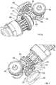
- a rotary hammeris shown in Figure 1 .
- the represented rotary hammerhas a hammer housing 1 which forms a gripping portion 3 at its rear end.
- a switch actuator 5 for switching an electric motor 7 of the rotary hammer on and offprojects into a grip opening 9.
- the grip opening 9is defined at its rear side by the gripping portion 5.
- a mains lead(not shown) which serves to connect the rotary hammer to a power source, is led out.
- an inner housing 11Located in the upper portion of the rotary hammer in Figure 1 is an inner housing 11, formed of half-shells and made from cast aluminium or the like, which extends forwards out of the rotary hammer housing 1 and in which a hammer spindle 13 is rotatably housed.
- the rear end of the hammer spindle 13forms a guide tube 15, provided in known manner with vent apertures, for a pneumatic hammer mechanism, and at the front end of which a tool holder 17 is held.
- the hammer mechanismcontains a piston 19 which is coupled, via a trunion 21 housed in it and a crank arm 23, with a crank pin 25 which sits eccentrically on the upper plate-shaped end 27 of a drive shaft 29.
- a reciprocating movement of the piston 19is carried out to alternately create a vacuum and an over-pressure in front of it, in order to move a ram 31 situated in the guide tube 15 correspondingly, so that this transmits impacts onto a beat piece 33, which passes them on to the rear end of a hammer bit, drill bit or chisel bit, not represented, which is inserted into the tool holder 17.
- This mode of operation and the structure of a pneumatic hammer mechanismare, as already mentioned, known and will therefore not be explained in more detail.
- the electric motor 7is arranged in the hammer housing 1 in such a way that its armature shaft 35 extends substantially perpendicular to the longitudinal axis of the hammer spindle 13 and the tool holder 17. Also, the longitudinal axis of the armature shaft 35 preferably lies in a plane with the longitudinal axis of the hammer spindle 13 and the tool holder 17.
- a pinion 37is formed which meshes with a first gear wheel 39 rotatably mounted on the drive shaft 29.
- the pinion 37also meshes with a second gear wheel 41 located on the side of the armature shaft 35 lying opposite the drive shaft 29 and non-rotatably secured on a shaft 43 rotatably housed in the inner housing 11.
- a bevel gearmeshes with the bevel teeth 45 of a drive sleeve 47.
- the drive sleeve 47is rotatably mounted via a friction bearing, but axially non displaceable on the hammer spindle 13 or on its rear part forming the guide tube 15 of the hammer mechanism.
- a coupling sleeve 49is axially displaceable but non-rotatable on the hammer spindle 13 in front of the drive sleeve 47 as a result of engagement with a splined section on the outer surface of the hammer spindle 13.
- the coupling sleeve 49can be displaced between a position of driving engagement, via teeth or projections formed at its rear end, with corresponding teeth or projections at the front end of the drive sleeve 47, and a forwardly displaced position in which there is no engagement between the coupling sleeve 49 and the drive sleeve 47.
- a helical spring 51loads the coupling sleeve 49 in the direction of the drive sleeve 47. The spring loading causes the coupling sleeve 49 to be biased into the position of driving engagement with the drive sleeve 47.
- the gear wheel 39 driven by the pinion 37 of the armature shaft 35is coupled with the drive shaft 29 in a manner yet to be described so that the crank pin 25 performs a circular movement which creates, via the crank arm 23, the reciprocating movement of the piston 19 in the guide tube 15 of the hammer mechanism.
- This type of driveis also known in rotary hammers in which the armature shaft 35 of the electric motor 7 lies perpendicular to the longitudinal axis of the hammer spindle 13 and the tool holder 17.
- a sleeve-shaped coupling part 55is non-rotatably mounted (through engagement with a splined section) but axially displaceable on the drive shaft 29 and has an annular flange 57 at its upper end.
- a spring 59has its upper end against the inner race of a ball bearing rotatably housing the drive shaft 29 and has its lower end engaging the annular flange 57. The spring force is directed downwards, i.e., in the direction of the gear wheel 39, and acts permanently on the sleeve-shaped coupling part 55.
- the sleeve-shaped coupling part 55has projections or teeth 61, represented for example in Figure 9 .
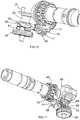
- the hammerhas a switching arrangement 63 to switch between the operating modes of the rotary hammer.
- the switching arrangement 63comprises a switching element such as an operating mode change knob 65 rotatable about a rotational axis.
- the knob 65is coupled to the switching arrangement 63, rotatably mounted on the hammer housing 1 and accessible to the user from the outside of the hammer housing 1.
- the knob 65is rigidly attached to a first gear 67 located between the hammer housing 1 (not shown in Figure 2 ) and the inner housing 11.
- the hammer housing 1(not shown in Figure 2 ) is disposed between the knob 65 and the first gear 67. Rotation of the knob 65 results in rotation of the first gear 67.
- the first gear 67meshes with a second gear 69, so that rotation of the first gear 67 results in rotation of the second gear 69.
- the first gear 67 and the second gear 69form a gear train 70.
- the second gear 69has a different number of teeth from the first gear 67 so that the rate of rotation of the first gear 67 is different from that of the second gear 69. More precisely, the first gear 67 has a lower number of teeth than the second gear 69. Therefore, the gear ratio of the gear train 70, defined by the ratio between the number of teeth of the first gear 67 and the number of teeth of the second gear 69, is less than 1.
- the first gear 67comprises between eight and twelve teeth, for example ten teeth
- the second gear 69comprises between eleven and seventeen teeth, for example fourteen teeth.
- the gear ratio as defined aboveis comprised between 0.5 and 0.9, and is for example equal to 0.7. This value of gear ratio leads to an increase of rotation of the knob 65 required to switch between the operation modes of the rotary hammer, compared to a classical switching mechanism which would comprise only one rotating element such as the second gear 69. This means that a greater rotation of the knob 65 is needed to switch between the operation modes of the rotary hammer. Therefore, this enables the user to avoid non wanted switching between the operation modes of the rotary hammer.
- the presence of the first gear 67 in the switching arrangement 63allows the knob 65 to be located at a central place on the side of the hammer housing 1, that is far from the bottom and the top of the rotary hammer, thereby enabling an easier access of the knob 65 for the user.
- the second gear 69is rigidly attached to a spindle 71 which locates within an aperture 73 formed through the inner housing 11.
- a cam 75is formed at an end of the spindle 71 where the second gear 69 is connected.
- the cam 75is formed on the spindle 71 inside of the inner housing 11.
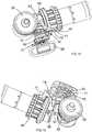
- a linear slider 77is slidably mounted on a guide 79 within the inner housing 11 for forward and reverse longitudinal sliding movement within the inner housing 11.
- the linear slider 77is biased into engagement with the cam 75.
- Rotation of the cam 75results in a forward linear sliding motion of the linear slider 77 against the biasing force acting upon it.
- the biasing force acting on the linear slider 77is a helical spring (not shown) located around the hammer spindle 13.
- Rotation of the cam 75enables the linear slider 77 to engage with the coupling sleeve 49 of the rotary drive mechanism. Therefore, rotation of the knob 65 results in a sliding movement of the coupling sleeve 49 via the first and second gears 67, 69, cam 75 and linear slider 77, thereby enabling the knob 65 to activate and deactivate the rotary drive mechanism.
- a pinextends from the spindle 71, parallel to the spindle 71, across the width of the inner housing 11, inside of the inner housing 11, along an internal axis.
- a U-shaped selector fork 83is pivotally mounted on the pin.
- the selector fork 83can freely pivot on the pin, about the internal axis.
- the selector fork 83comprises two arms 85 which locate within a groove 87 formed within the sleeve-shaped coupling part 55. Pivotal movement of the selector fork 83 causes a sliding movement of the sleeve-shaped coupling part 55.
- the spring 59biases the sleeve-shaped coupling part 55 and hence the selector fork 83 to a predetermined position, for example to the lower position of the sleeve-shaped coupling part 55 as described above and as represented for example in Figures 14 and 15 , in which the sleeve-shaped coupling part 55 is in positive engagement with the gear wheel 39, and in which thereby the hammer mechanism of the rotary hammer is driven.
- the spindle 71also comprises a blocking member 88 disposed at an end of the spindle 71 opposite to the cam 75 and preventing further pivotal movement of the selector fork 83.
- the pinis disposed in the rotary hammer so that the internal axis is substantially perpendicular to the longitudinal axis of the hammer spindle 13, and so that there is a lateral offset between the rotational axis of the knob 65 and the internal axis of the selector fork 83.
- a drive member 89is formed on the side of the selector fork 83, and a protuberance 91 is formed on the end of the spindle 71, adjacent to the cam 75.
- the drive member 89 and the protuberance 91are angularly offset from each other such that they only engage each other over a portion of the rotational movement of the spindle 71. Specifically, within a first angular range of the rotational movement, the protuberance 91 does not engage the drive member 89 and rotation of the spindle 71 does not drive the selector fork 83.
- the protuberance 91engages the drive member 89 such that rotation of the spindle 71 drivingly rotates the selector fork 83.
- the protuberance 91engages the drive member 89 and further rotation of the spindle 71 (within said second angular range) drivingly rotates the selector fork 83.
- the design of the cam 75 and location of the protuberance 91 and drive member 89are such that rotation of the knob 65 through a predetermined range of angular movement results in the activation and deactivation of the rotary drive mechanism and the activation and deactivation of the hammer mechanism so that the rotary hammer can operate in a drill only mode, a hammer drilling mode, a hammer only mode or a chiselling mode.
- the knob 65is twisted counter clockwise out of the position of Figures 9 and 10 into the position of Figures 11 to 15 , the knob 65 is in the initial position again, and therefore the rotary hammer operates in the hammering and drilling mode. If the knob is further twisted counter clockwise out of the position of Figures 11 to 15 into the position of Figures 5 to 8 , the cam 75 engages the linear slider 77, and there is thereby a forward displacement of the linear slider 77. The coupling sleeve 49 is displaced and is disengaged from the drive sleeve 47. Thus, the drive for the rotation of the hammer spindle 13 is disengaged.
Landscapes
- Engineering & Computer Science (AREA)
- Mechanical Engineering (AREA)
- Percussive Tools And Related Accessories (AREA)
- Drilling And Boring (AREA)
Description
- The present disclosure relates to a rotary hammer, and in particular a rotary hammer having three or more modes of operation.
- Rotary hammers which can switch between three modes of operation, namely between a hammer only mode, a drill only mode, and a hammer and drill mode, are known. Rotary hammers of this type typically comprise a hammer spindle mounted for rotation within a housing which can be selectively driven by a rotary drive mechanism within the housing. The rotary drive mechanism is driven by a motor also located within the housing. The hammer spindle rotatingly drives a tool holder of the rotary hammer which in turn rotatingly drives a cutting tool, such as a hammer bit or a drill bit, releaseably secured within it. Within the hammer spindle is generally mounted a piston which can be reciprocatingly driven by a hammer drive mechanism which translates the rotary drive of the motor to a reciprocating drive of the piston. A ram, also slidably mounted within the hammer spindle, forward of the piston, is reciprocatingly driven by the piston due to successive over and under pressures in an air cushion formed within the hammer spindle between the piston and the ram. The ram repeatedly impacts a beat piece slidably located within the hammer spindle forward of the ram, which in turn transfers the forward impacts from the ram to the cutting tool releasably secured, for limited reciprocation, within the tool holder at the front of the rotary hammer. A mode change mechanism can selectively engage and disengage the rotary drive to the hammer spindle and/or the reciprocating drive to the piston. Thus, in the hammer only mode, there is only the reciprocating drive of the piston, in the drill only mode, there is only the rotary drive of the hammer spindle, and in the hammer and drill mode, there are both the rotary drive of the hammer spindle and the reciprocating drive of the piston. The specification of
EP 0 975 454 B1 discloses such a rotary hammer.US2005/0224242 comprises a rotary hammer have in, all of the precharacteristics features of claim 1. EP1950009 andUS2005/0224242 disclose hammer drills with mode change mechanisms.- At least in certain embodiments, the present invention sets out to improve the operation of such rotary rammers. In particular, the present invention sets out to improve the switching mechanism between the three or more modes of operation.
- The present invention is related to a rotary hammer, and in particular a rotary hammer having three or more modes of operation.
- According to the invention, there is provided a rotary hammer in accordance with claim 1.
- The gear train has a gear ratio which is comprised between 0.5 and 0.9. This value of gear ratio leads to an increase of rotation of the switching element required to switch between the operation modes of the rotary hammer, compared to a classical switching mechanism which would comprise only one rotating element. This means that a greater rotation of the switching element is needed to switch between the operation modes of the rotary hammer. Therefore, this enables the user to avoid non wanted switching between the operation modes of the rotary hammer. Moreover, the presence of the first gear in the switching arrangement allows the switching element to be located at a place on the side of the hammer housing that is far from the bottom and the top of the rotary hammer, thereby enabling an easier access of the switching element for the user.
- The switching arrangement can comprise a coupling part axially displaceable on the drive shaft of the hammer mechanism between a lower position in which the drive shaft is coupled to the armature shaft and an upper position in which the drive shaft is decoupled from the armature shaft. The switching arrangement may comprise a selector for displacing the coupling part between the lower position and the upper position. The selector may extend along an internal axis which is substantially perpendicular to the longitudinal axis of the hammer spindle. The selector can be rotatable about the internal axis. The rotary hammer can comprise a lateral offset between the rotational axis of the switching element and the internal axis of the selector.
- The coupling part may be formed with a sleeve comprising a flange. The selector may be a U-shaped member, for example a fork, comprising two arms for engaging a lower part of the flange of the sleeve-shaped coupling part. The selector may comprise a drive member. The cam portion may comprise a protuberance. The drive member and the protuberance may be arranged so that the protuberance engages the drive member to pivot the selector when the switching element is rotated. The protuberance and the drive member can be adapted such that the protuberance engages the drive member over only a portion of the rotational movement of the cam portion. For example, the protuberance and the drive member can be angularly offset from each other.
- The armature shaft of the motor can be arranged substantially perpendicular to the longitudinal axis of the hammer spindle, and can drive a drive sleeve which is arranged rotatable on the hammer spindle and which can be coupled with the hammer spindle via a coupling sleeve which sits non-rotatable but axially displaceable on the hammer spindle. The cam portion of the switching arrangement may act on the coupling sleeve via a linear slider part. The linear slider part can be moved parallel to the axis of the hammer spindle so that the coupling sleeve can be moved between a position of engagement with the drive sleeve and a release position separated from the drive sleeve.
- An embodiment of the present invention will now be described, by way of example only, with reference to the accompanying figures, in which:
Figure 1 shows, partly open and in section, a rotary hammer according to the present invention;Figure 2 shows a partial perspective view of the rotary hammer according to the present invention;Figure 3 shows a perspective detailed view of the switching arrangement of the rotary hammer according to the present invention;Figure 4 shows a partial bottom view of the rotary hammer according to the present invention;Figure 5 shows a partial side perspective view of the rotary hammer according to the present invention, the rotary hammer being in a pure hammering mode;Figures 6 and 7 show partial bottom perspective views of the rotary hammer according to the present invention, the rotary hammer being in the pure hammering mode;Figure 8 shows a partial side view of the rotary hammer according to the present invention, the rotary hammer being in the pure hammering mode;Figures 9 and10 show partial side perspective views of the rotary hammer according to the present invention, the rotary hammer being in a pure drilling mode;Figure 11 shows a partial side perspective view of the rotary hammer according to the present invention, the rotary hammer being in a hammering and drilling mode;Figures 12 and 13 show partial bottom perspective views of the rotary hammer according to the present invention, the rotary hammer being in the hammering and drilling mode;Figure 14 shows a partial side perspective view of the rotary hammer according to the present invention, the rotary hammer being in the hammering and drilling mode; andFigure 15 shows a partial rear perspective view of the rotary hammer according to the present invention, the rotary hammer being in the hammering and drilling mode.- A rotary hammer is shown in
Figure 1 . The represented rotary hammer has a hammer housing 1 which forms a grippingportion 3 at its rear end. Aswitch actuator 5 for switching anelectric motor 7 of the rotary hammer on and off projects into a grip opening 9. Thegrip opening 9 is defined at its rear side by the grippingportion 5. In the rear lower portion of thehammer housing 3, a mains lead (not shown) which serves to connect the rotary hammer to a power source, is led out. - Located in the upper portion of the rotary hammer in
Figure 1 is aninner housing 11, formed of half-shells and made from cast aluminium or the like, which extends forwards out of the rotary hammer housing 1 and in which ahammer spindle 13 is rotatably housed. The rear end of thehammer spindle 13 forms aguide tube 15, provided in known manner with vent apertures, for a pneumatic hammer mechanism, and at the front end of which atool holder 17 is held. The hammer mechanism contains apiston 19 which is coupled, via atrunion 21 housed in it and acrank arm 23, with acrank pin 25 which sits eccentrically on the upper plate-shaped end 27 of adrive shaft 29. A reciprocating movement of thepiston 19 is carried out to alternately create a vacuum and an over-pressure in front of it, in order to move aram 31 situated in theguide tube 15 correspondingly, so that this transmits impacts onto abeat piece 33, which passes them on to the rear end of a hammer bit, drill bit or chisel bit, not represented, which is inserted into thetool holder 17. This mode of operation and the structure of a pneumatic hammer mechanism are, as already mentioned, known and will therefore not be explained in more detail. - The
electric motor 7 is arranged in the hammer housing 1 in such a way that itsarmature shaft 35 extends substantially perpendicular to the longitudinal axis of thehammer spindle 13 and thetool holder 17. Also, the longitudinal axis of thearmature shaft 35 preferably lies in a plane with the longitudinal axis of thehammer spindle 13 and thetool holder 17. To drive the hammer mechanism, at the upper end of thearmature shaft 35 inFigure 1 , apinion 37 is formed which meshes with afirst gear wheel 39 rotatably mounted on thedrive shaft 29. Thepinion 37 also meshes with asecond gear wheel 41 located on the side of thearmature shaft 35 lying opposite thedrive shaft 29 and non-rotatably secured on ashaft 43 rotatably housed in theinner housing 11. At the upper end of theshaft 43, a bevel gear meshes with thebevel teeth 45 of adrive sleeve 47. Thedrive sleeve 47 is rotatably mounted via a friction bearing, but axially non displaceable on thehammer spindle 13 or on its rear part forming theguide tube 15 of the hammer mechanism. Acoupling sleeve 49 is axially displaceable but non-rotatable on thehammer spindle 13 in front of thedrive sleeve 47 as a result of engagement with a splined section on the outer surface of thehammer spindle 13. Thecoupling sleeve 49 can be displaced between a position of driving engagement, via teeth or projections formed at its rear end, with corresponding teeth or projections at the front end of thedrive sleeve 47, and a forwardly displaced position in which there is no engagement between thecoupling sleeve 49 and thedrive sleeve 47. Ahelical spring 51 loads thecoupling sleeve 49 in the direction of thedrive sleeve 47. The spring loading causes thecoupling sleeve 49 to be biased into the position of driving engagement with thedrive sleeve 47. - If the driving engagement is initially blocked by abutment of the end faces of the projections or teeth of the
coupling sleeve 49 against the end face of the projections or teeth of thedrive sleeve 47, a positive driving engagement is then automatically established when there is a relative rotation of thecoupling sleeve 49 and thedrive sleeve 47 due, for example, to rotation of thedrive sleeve 47 by theshaft 43. - Thus, rotation of the
armature shaft 35 via thegear wheel 41 and thebevel teeth 45 of theshaft 43 causes rotation of thedrive sleeve 47. And, when there is a positive engagement betweendrive sleeve 47 and thecoupling sleeve 49, thehammer spindle 13 and thetool holder 17 are rotated. Accordingly, in the absence of a positive driving engagement between thedrive sleeve 47 and thecoupling sleeve 49, thehammer spindle 13 is not rotated despite rotation of thedrive sleeve 47. If thecoupling sleeve 49 with protrusions at the front end projecting radially outwards enter into a positive engagement with corresponding recesses in a housing-fixedzone 53, the result is a position of thecoupling sleeve 49 and thus of thehammer spindle 13 including thetool holder 17 which is locked against rotation. This mode of operation of thecoupling sleeve 49 is known. - To drive the hammer mechanism, the
gear wheel 39 driven by thepinion 37 of thearmature shaft 35 is coupled with thedrive shaft 29 in a manner yet to be described so that thecrank pin 25 performs a circular movement which creates, via thecrank arm 23, the reciprocating movement of thepiston 19 in theguide tube 15 of the hammer mechanism. This type of drive is also known in rotary hammers in which thearmature shaft 35 of theelectric motor 7 lies perpendicular to the longitudinal axis of thehammer spindle 13 and thetool holder 17. - As shown in
Figure 1 , a sleeve-shapedcoupling part 55 is non-rotatably mounted (through engagement with a splined section) but axially displaceable on thedrive shaft 29 and has anannular flange 57 at its upper end. Aspring 59 has its upper end against the inner race of a ball bearing rotatably housing thedrive shaft 29 and has its lower end engaging theannular flange 57. The spring force is directed downwards, i.e., in the direction of thegear wheel 39, and acts permanently on the sleeve-shapedcoupling part 55. At the lower end, the sleeve-shapedcoupling part 55 has projections orteeth 61, represented for example inFigure 9 . In the lower position of the sleeve-shapedcoupling part 55, theteeth 61 are in positive engagement with corresponding recesses (not shown) in the body of thegear wheel 39. In this position, rotation of thegear wheel 39 rotates thedrive shaft 29 which is in positive engagement with the sleeve-shapedcoupling part 55. - As shown in
Figure 2 , the hammer has a switchingarrangement 63 to switch between the operating modes of the rotary hammer. The switchingarrangement 63 comprises a switching element such as an operatingmode change knob 65 rotatable about a rotational axis. Theknob 65 is coupled to the switchingarrangement 63, rotatably mounted on the hammer housing 1 and accessible to the user from the outside of the hammer housing 1. Theknob 65 is rigidly attached to afirst gear 67 located between the hammer housing 1 (not shown inFigure 2 ) and theinner housing 11. The hammer housing 1 (not shown inFigure 2 ) is disposed between theknob 65 and thefirst gear 67. Rotation of theknob 65 results in rotation of thefirst gear 67. - As shown in
Figure 3 , thefirst gear 67 meshes with asecond gear 69, so that rotation of thefirst gear 67 results in rotation of thesecond gear 69. Thefirst gear 67 and thesecond gear 69 form agear train 70. Thesecond gear 69 has a different number of teeth from thefirst gear 67 so that the rate of rotation of thefirst gear 67 is different from that of thesecond gear 69. More precisely, thefirst gear 67 has a lower number of teeth than thesecond gear 69. Therefore, the gear ratio of thegear train 70, defined by the ratio between the number of teeth of thefirst gear 67 and the number of teeth of thesecond gear 69, is less than 1. Thefirst gear 67 comprises between eight and twelve teeth, for example ten teeth, whereas thesecond gear 69 comprises between eleven and seventeen teeth, for example fourteen teeth. The gear ratio as defined above is comprised between 0.5 and 0.9, and is for example equal to 0.7. This value of gear ratio leads to an increase of rotation of theknob 65 required to switch between the operation modes of the rotary hammer, compared to a classical switching mechanism which would comprise only one rotating element such as thesecond gear 69. This means that a greater rotation of theknob 65 is needed to switch between the operation modes of the rotary hammer. Therefore, this enables the user to avoid non wanted switching between the operation modes of the rotary hammer. Moreover, the presence of thefirst gear 67 in the switchingarrangement 63 allows theknob 65 to be located at a central place on the side of the hammer housing 1, that is far from the bottom and the top of the rotary hammer, thereby enabling an easier access of theknob 65 for the user. - As shown in
Figure 4 and 5 , thesecond gear 69 is rigidly attached to aspindle 71 which locates within anaperture 73 formed through theinner housing 11. Acam 75 is formed at an end of thespindle 71 where thesecond gear 69 is connected. Thecam 75 is formed on thespindle 71 inside of theinner housing 11. - As is it shown in
Figure 5 to 7 , alinear slider 77 is slidably mounted on aguide 79 within theinner housing 11 for forward and reverse longitudinal sliding movement within theinner housing 11. Thelinear slider 77 is biased into engagement with thecam 75. Rotation of thecam 75 results in a forward linear sliding motion of thelinear slider 77 against the biasing force acting upon it. The biasing force acting on thelinear slider 77 is a helical spring (not shown) located around thehammer spindle 13. Rotation of thecam 75 enables thelinear slider 77 to engage with thecoupling sleeve 49 of the rotary drive mechanism. Therefore, rotation of theknob 65 results in a sliding movement of thecoupling sleeve 49 via the first andsecond gears cam 75 andlinear slider 77, thereby enabling theknob 65 to activate and deactivate the rotary drive mechanism. - A pin (not shown) extends from the
spindle 71, parallel to thespindle 71, across the width of theinner housing 11, inside of theinner housing 11, along an internal axis. As shown inFigure 5 to 7 , aU-shaped selector fork 83 is pivotally mounted on the pin. Theselector fork 83 can freely pivot on the pin, about the internal axis. Theselector fork 83 comprises twoarms 85 which locate within agroove 87 formed within the sleeve-shapedcoupling part 55. Pivotal movement of theselector fork 83 causes a sliding movement of the sleeve-shapedcoupling part 55. The spring 59 (shown inFigure 1 ) biases the sleeve-shapedcoupling part 55 and hence theselector fork 83 to a predetermined position, for example to the lower position of the sleeve-shapedcoupling part 55 as described above and as represented for example inFigures 14 and 15 , in which the sleeve-shapedcoupling part 55 is in positive engagement with thegear wheel 39, and in which thereby the hammer mechanism of the rotary hammer is driven. Thespindle 71 also comprises a blockingmember 88 disposed at an end of thespindle 71 opposite to thecam 75 and preventing further pivotal movement of theselector fork 83. The pin is disposed in the rotary hammer so that the internal axis is substantially perpendicular to the longitudinal axis of thehammer spindle 13, and so that there is a lateral offset between the rotational axis of theknob 65 and the internal axis of theselector fork 83. - As shown in
Figure 8 , adrive member 89 is formed on the side of theselector fork 83, and aprotuberance 91 is formed on the end of thespindle 71, adjacent to thecam 75. Thedrive member 89 and theprotuberance 91 are angularly offset from each other such that they only engage each other over a portion of the rotational movement of thespindle 71. Specifically, within a first angular range of the rotational movement, theprotuberance 91 does not engage thedrive member 89 and rotation of thespindle 71 does not drive theselector fork 83. Within a second angular range of the rotational movement, theprotuberance 91 engages thedrive member 89 such that rotation of thespindle 71 drivingly rotates theselector fork 83. Thus, when thespindle 71 is rotated within said first angular range, there is no engagement of theprotuberance 91 and thedrive member 89. Once thespindle 71 has been rotated through the first angular range, theprotuberance 91 engages thedrive member 89 and further rotation of the spindle 71 (within said second angular range) drivingly rotates theselector fork 83. This results in a rotational movement of theselector fork 83 which in turn lifts the sleeve-shapedcoupling part 55 against the biasing force of thespring 59, to an upper position in which the sleeve-shapedcoupling part 55 no longer engages thegear wheel 39, as shown inFigure 9 and10 . As such, rotation of theknob 65 results in the activation and deactivation of thepiston 19. - The design of the
cam 75 and location of theprotuberance 91 and drivemember 89 are such that rotation of theknob 65 through a predetermined range of angular movement results in the activation and deactivation of the rotary drive mechanism and the activation and deactivation of the hammer mechanism so that the rotary hammer can operate in a drill only mode, a hammer drilling mode, a hammer only mode or a chiselling mode. - The operation of the rotary hammer according to the present invention will now be described with reference to
Figures 5 to 15 . Initially, the sleeve-shapedcoupling part 55 is biased in its lower position by thespring 59, such that the sleeve-shapedcoupling part 55 is engaged with thegear wheel 39. At the same time, thecoupling sleeve 49 is in positive engagement with thedrive sleeve 47, and thereby thehammer spindle 13 rotates about the hammer longitudinal axis. Therefore, both the hammer mechanism and the rotary drive mechanism are driven. The rotary hammer then operates initially in the hammering and drilling mode. This operating mode is represented inFigures 11 to 15 . - If the
knob 65 is twisted clockwise out of the position ofFigure 11 to 15 into the position ofFigures 9 and10 , thefirst gear 67 and thesecond gear 69 rotate, which causes theprotuberance 91 to engage thedrive member 89, which causes thespindle 71 to rotate. Therefore theselector fork 83 pivots about the internal axis and thearms 85 to engage the lower surface of theflange 57 and lift the sleeve-shapedcoupling part 55 against the force of thespring 59 out of driving engagement with thegear wheel 39. In this position, shown inFigures 9 and10 , the hammer mechanism is not driven when thegear wheel 39 is driven, i.e. the hammer mechanism is deactivated. Thelinear slider 77 still lies against thespindle 71 opposite to thecam 75, whereby thecoupling sleeve 49 is biased into positive engagement with the drive sleeve 16. Therefore thehammer spindle 13 is driven rotationally upon rotation of thearmature shaft 35. Therefore the rotary hammer operates in a pure drilling mode. - If the
knob 65 is twisted counter clockwise out of the position ofFigures 9 and10 into the position ofFigures 11 to 15 , theknob 65 is in the initial position again, and therefore the rotary hammer operates in the hammering and drilling mode.
If the knob is further twisted counter clockwise out of the position ofFigures 11 to 15 into the position ofFigures 5 to 8 , thecam 75 engages thelinear slider 77, and there is thereby a forward displacement of thelinear slider 77. Thecoupling sleeve 49 is displaced and is disengaged from thedrive sleeve 47. Thus, the drive for the rotation of thehammer spindle 13 is disengaged. However, since there is still no positive engagement between the recesses in the housing-fixedzone 53 and the projections or teeth at the front end of thecoupling sleeve 17, thehammer spindle 13 is not yet secured against non driven rotation. The rotary hammer is now in the pure hammering mode. - Further counter clockwise rotation of the
first gear 67 and thus of thesecond gear 69 results in a further forward displacement of thecoupling sleeve 49. The teeth or projections protruding radially outwards at the front end of thecoupling sleeve 49 enter into positive engagement with the corresponding recesses in the housing-fixedzone 53. Thus, thehammer spindle 13 is locked against rotation. Thecoupling sleeve 49 is loaded forwardly into engagement with the housing-fixedzone 53. Accordingly, if the end faces of the teeth of thecoupling sleeve 49 and the housing-fixedzone 53 are initially abutted preventing full engagement, thecoupling sleeve 49 is fully engaged with the housing-fixedzone 53 when thecoupling sleeve 49 and the housing-fixedzone 53 are relatively rotated. The rotary hammer is now in the chiselling mode with thehammer spindle 13 locked. - It will be appreciated that various changes and modifications can be made to the rotary hammer described above without departing from the scope of the present invention as defined by the claims.
Claims (9)
- A rotary hammer comprising:a hammer housing (1);a motor (3) having an armature shaft (35);a hammer spindle (13) rotatably mounted about a longitudinal axis in the hammer housing (1);a tool holder (17) provided at a front end of the hammer housing (1) and being rotatingly driven by the motor (7) about the longitudinal axis of the hammer spindle (13);a hammer mechanism provided in the hammer housing (1) for generating impacts acting on the rear end of a bit inserted into the tool holder (7), the hammer mechanism having a drive shaft (29) able to be selectively coupled with the armature shaft (35); anda switching arrangement (63) for switching the rotary hammer between at least a pure drilling mode, a hammer drilling mode and a pure hammering mode, having a switching element (65) rotatable from the outside of the hammer housing about a rotational axis, the switching arrangement (63) having a cam portion (75) for switching the rotary hammer between at least two modes of operation;wherein the switching arrangement (63) comprises a gear train (67, 69) disposed between the switching element (65) and the cam portion (75);wherein the gear train comprises a first gear (67) rigidly connected to the switching element (65) so that rotation of the switching element (65) results in rotation of the first gear (67) and a second gear (69) rigidly connected to the cam portion (75),characterised in that the first and second gears are arranged to mesh directly with each other, so that rotation of the first gear results in rotation of the second gear (69); andin that the gear ratio of the gear train (67, 69) is comprised between 0.5 and 0.9.
- A rotary hammer as claimed in claim 1, wherein the switching arrangement (63) comprises a coupling part (55) axially displaceable on the drive shaft (29)of the hammer mechanism between a lower position in which the drive shaft (29) is coupled to the armature shaft (35) and an upper position in which the drive shaft (29) is decoupled from the armature shaft (35), and wherein the switching arrangement (63) comprises a selector (83) for displacing the coupling part (55)between the lower position and the upper position.
- A rotary hammer as claimed in claim 2, wherein the selector (83) extends along an internal axis which is substantially perpendicular to the longitudinal axis of the hammer spindle (13) and wherein the selector (83) is rotatable about the internal axis.
- A rotary hammer as claimed in claim 3, comprising a lateral offset between the rotational axis of the switching element (65) and the internal axis of the selector (83).
- A rotary hammer as claimed in any one of claims 2 to 4, wherein the coupling part (55) is formed with a sleeve comprising a flange (57) and wherein the selector (83) comprises a fork having two arms (85) for engaging a lower part of the flange (57) of the sleeve-shaped coupling part (55).
- A rotary hammer as claimed in any one of claims 2 to 5, wherein the selector (83) comprises a drive member (89) and wherein the switching arrangement (63) comprises a protuberance, the drive member (89) and the protuberance (91) being arranged so that the protuberance (91) adjacent to the cam portion (75) engages the drive member (89) to pivot the selector (83) when the switching element (65)is rotated.
- A rotary hammer as claimed in claim 6, wherein the protuberance (91) and the drive member (89) are adapted such that the protuberance (91) engages the drive member (89) over only a portion of the rotational movement of the cam portion (75).
- A rotary hammer as claimed in any one of the preceding claims, wherein the armature shaft (35) of the motor (7) is arranged substantially perpendicular to the axis of the hammer spindle (13), and drives a drive sleeve (47) which is arranged rotatably on the hammer spindle (13) and which can be coupled with the hammer spindle (13) via a coupling sleeve (41) which sits non-rotatably but axially displaceable on the hammer spindle (13).
- A rotary hammer as claimed in claim 8, wherein the cam portion (75) of the switching arrangement (63) acts on the coupling sleeve (49) via a linear slider part (77) which can be moved parallel to the longitudinal axis of the hammer splindle (13) so that the coupling sleeve (49) can be moved between a position of engagement with the drive sleeve (47) and a release position separated from the drive sleeve (47).
Priority Applications (1)
| Application Number | Priority Date | Filing Date | Title |
|---|---|---|---|
| EP16155349.0AEP3034243B1 (en) | 2013-12-11 | 2014-11-11 | Rotary hammer |
Applications Claiming Priority (1)
| Application Number | Priority Date | Filing Date | Title |
|---|---|---|---|
| GB201321893AGB201321893D0 (en) | 2013-12-11 | 2013-12-11 | Rotary Hammer |
Related Child Applications (2)
| Application Number | Title | Priority Date | Filing Date |
|---|---|---|---|
| EP16155349.0ADivisionEP3034243B1 (en) | 2013-12-11 | 2014-11-11 | Rotary hammer |
| EP16155349.0ADivision-IntoEP3034243B1 (en) | 2013-12-11 | 2014-11-11 | Rotary hammer |
Publications (2)
| Publication Number | Publication Date |
|---|---|
| EP2883660A1 EP2883660A1 (en) | 2015-06-17 |
| EP2883660B1true EP2883660B1 (en) | 2019-07-17 |
Family
ID=50000538
Family Applications (2)
| Application Number | Title | Priority Date | Filing Date |
|---|---|---|---|
| EP16155349.0AActiveEP3034243B1 (en) | 2013-12-11 | 2014-11-11 | Rotary hammer |
| EP14192715.2AActiveEP2883660B1 (en) | 2013-12-11 | 2014-11-11 | Rotary hammer |
Family Applications Before (1)
| Application Number | Title | Priority Date | Filing Date |
|---|---|---|---|
| EP16155349.0AActiveEP3034243B1 (en) | 2013-12-11 | 2014-11-11 | Rotary hammer |
Country Status (4)
| Country | Link |
|---|---|
| US (1) | US9873192B2 (en) |
| EP (2) | EP3034243B1 (en) |
| CN (1) | CN104708602B (en) |
| GB (1) | GB201321893D0 (en) |
Families Citing this family (6)
| Publication number | Priority date | Publication date | Assignee | Title |
|---|---|---|---|---|
| US10528073B2 (en)* | 2015-03-04 | 2020-01-07 | Snap-On Incorporated | Rotatable control device with axial translation |
| JP6342973B2 (en)* | 2016-11-24 | 2018-06-13 | ファナック株式会社 | Manual pulse generator |
| DE18197782T1 (en)* | 2017-09-30 | 2019-07-04 | Positec Power Tools (Suzhou) Co., Ltd | impact tool |
| JP7236921B2 (en)* | 2019-04-18 | 2023-03-10 | 株式会社マキタ | impact tool |
| DE102020114634B4 (en)* | 2019-07-18 | 2023-07-20 | Defond Components Limited | Control assembly for use with an electrical device and a corresponding electrical device |
| US12349902B2 (en)* | 2020-07-09 | 2025-07-08 | Covidien Lp | Powered handle assembly for surgical devices |
Citations (1)
| Publication number | Priority date | Publication date | Assignee | Title |
|---|---|---|---|---|
| US20050224242A1 (en)* | 2004-04-08 | 2005-10-13 | Rory Britz | Hammer drill |
Family Cites Families (37)
| Publication number | Priority date | Publication date | Assignee | Title |
|---|---|---|---|---|
| US4085337A (en)* | 1975-10-07 | 1978-04-18 | Moeller Wolfgang W | Electric drill multi-functional apparatus |
| US4627299A (en) | 1984-12-20 | 1986-12-09 | Facet Enterprises, Inc. | Engine starter gearing |
| DE3527091A1 (en) | 1985-07-29 | 1987-01-29 | Hilti Ag | DRILLING DEVICE |
| DE3538166A1 (en)* | 1985-10-26 | 1987-04-30 | Hilti Ag | DRILL HAMMER WITH TURN LOCK |
| JP3424880B2 (en) | 1995-08-18 | 2003-07-07 | 株式会社マキタ | Hammer drill |
| DE19545260A1 (en)* | 1995-11-24 | 1997-05-28 | Black & Decker Inc | Hammer drill |
| DE19717712A1 (en) | 1997-04-18 | 1998-10-22 | Black & Decker Inc | Hammer drill |
| DE19724531B4 (en) | 1997-06-11 | 2005-07-14 | Robert Bosch Gmbh | Rotary Hammer |
| JP3609626B2 (en) | 1998-09-16 | 2005-01-12 | 株式会社マキタ | Hammer drill |
| DE10033100A1 (en) | 2000-07-07 | 2002-01-17 | Hilti Ag | Combined electric hand tool device |
| DE10058994B4 (en) | 2000-11-28 | 2005-04-21 | Robert Bosch Gmbh | Chisel and hammer |
| DE10205030A1 (en) | 2002-02-07 | 2003-08-21 | Hilti Ag | Operating mode switching unit of a hand machine tool |
| DE10261030A1 (en) | 2002-12-24 | 2004-07-08 | Robert Bosch Gmbh | Rotary Hammer |
| GB0311045D0 (en) | 2003-05-14 | 2003-06-18 | Black & Decker Inc | Rotary hammer |
| DE10355107B3 (en) | 2003-11-24 | 2005-08-11 | Itw-Befestigungssysteme Gmbh | Selektordrehschalter |
| DE10356029A1 (en)* | 2003-12-01 | 2005-06-23 | Hilti Ag | Hand tool machine for construction industry, has mode switchable rotary switch that meshes with tooth of switch cam shaft of one transformation module e.g. ratchet, in switching angle to select operation mode of rotary tool |
| DE102004025951A1 (en) | 2004-05-27 | 2005-12-22 | Robert Bosch Gmbh | Hand tool, in particular drill and / or percussion hammer |
| JP4515181B2 (en) | 2004-07-20 | 2010-07-28 | 株式会社マキタ | Electric hammer drill |
| DE102004055236A1 (en) | 2004-11-16 | 2006-05-18 | Robert Bosch Gmbh | Hand tool machine e.g. hammer drill, for releasing of screw, has gear that stands in contact with connecting sleeve, where another connecting sleeve has external tooth that rotatably and continuously stands in contact with sprocket pinion |
| US7306048B2 (en) | 2004-11-24 | 2007-12-11 | Hitachi Koki Co., Ltd. | Hammer drill having switching mechanism for switching operation modes |
| EP1674207B1 (en) | 2004-12-23 | 2008-12-10 | BLACK & DECKER INC. | Power tool |
| DE102005047353A1 (en)* | 2005-10-04 | 2007-04-05 | Robert Bosch Gmbh | Electric-powered machine tool e.g. hand-operated power drill, for use in pistol construction, has flange to drive train and divided into drive end and gear end bearing bracket units connected with each other by vibration damping unit |
| JP4812471B2 (en) | 2006-03-09 | 2011-11-09 | 株式会社マキタ | Work tools |
| JP4664240B2 (en)* | 2006-06-12 | 2011-04-06 | 株式会社マキタ | Driving tool |
| CN2920563Y (en) | 2006-07-11 | 2007-07-11 | 王文江 | Light single-span four function electric hammer |
| DE102006000515A1 (en) | 2006-12-12 | 2008-06-19 | Hilti Ag | Electric hand tool |
| DE102006059078A1 (en)* | 2006-12-14 | 2008-06-19 | Robert Bosch Gmbh | Electric device with snap-on rotatable control element |
| JP2008183633A (en)* | 2007-01-26 | 2008-08-14 | Makita Corp | Hammer drill |
| JP5009005B2 (en)* | 2007-02-15 | 2012-08-22 | 株式会社マキタ | Hammer drill |
| DE102007009986A1 (en) | 2007-03-02 | 2008-09-04 | Robert Bosch Gmbh | Hand tool, especially a hammer drill or chisel hammer, comprises a switch spring with a receiving region for holding a transmission element of a mounted actuating unit during assembly of a gear housing and a gear unit |
| JP4981506B2 (en) | 2007-04-12 | 2012-07-25 | 株式会社マキタ | Hammer drill |
| CN201253840Y (en)* | 2008-08-15 | 2009-06-10 | 苏州宝时得电动工具有限公司 | Hammer drill type power tool |
| US9193053B2 (en)* | 2008-09-25 | 2015-11-24 | Black & Decker Inc. | Hybrid impact tool |
| US8251158B2 (en)* | 2008-11-08 | 2012-08-28 | Black & Decker Inc. | Multi-speed power tool transmission with alternative ring gear configuration |
| DE102009050013A1 (en) | 2009-10-21 | 2011-04-28 | Metabowerke Gmbh | Motor driven power tool |
| CN202239771U (en)* | 2011-10-18 | 2012-05-30 | 东莞市妙达电动工具制造有限公司 | Novel multifunctional electric impact drill |
| US9486904B2 (en)* | 2012-05-31 | 2016-11-08 | Black & Decker Inc. | Fastening tool nosepiece insert |
- 2013
- 2013-12-11GBGB201321893Apatent/GB201321893D0/ennot_activeCeased
- 2014
- 2014-11-11EPEP16155349.0Apatent/EP3034243B1/enactiveActive
- 2014-11-11EPEP14192715.2Apatent/EP2883660B1/enactiveActive
- 2014-12-04USUS14/560,660patent/US9873192B2/enactiveActive
- 2014-12-11CNCN201410764329.5Apatent/CN104708602B/ennot_activeExpired - Fee Related
Patent Citations (1)
| Publication number | Priority date | Publication date | Assignee | Title |
|---|---|---|---|---|
| US20050224242A1 (en)* | 2004-04-08 | 2005-10-13 | Rory Britz | Hammer drill |
Also Published As
| Publication number | Publication date |
|---|---|
| EP3034243A1 (en) | 2016-06-22 |
| US9873192B2 (en) | 2018-01-23 |
| GB201321893D0 (en) | 2014-01-22 |
| CN104708602B (en) | 2016-08-24 |
| EP2883660A1 (en) | 2015-06-17 |
| EP3034243B1 (en) | 2021-02-24 |
| CN104708602A (en) | 2015-06-17 |
| US20150158168A1 (en) | 2015-06-11 |
Similar Documents
| Publication | Publication Date | Title |
|---|---|---|
| EP2883660B1 (en) | Rotary hammer | |
| EP1987925B1 (en) | Hammer drill | |
| US6015017A (en) | Rotary hammer | |
| EP2062697B1 (en) | A hammer-drill with mode collar | |
| EP1832393B1 (en) | Power tool | |
| EP3012071B1 (en) | Pneumatic hammer | |
| US6109364A (en) | Rotary hammer | |
| US7306049B2 (en) | Mode change switch for power tool | |
| US7647985B2 (en) | Hammer drill | |
| JP2002059375A (en) | Hand power tool device | |
| JP4446248B2 (en) | Hammer drill | |
| EP2883661B1 (en) | Rotary hammer | |
| JP2009241229A (en) | Hammer drill | |
| JP6735118B2 (en) | Hammer drill | |
| EP3812097B1 (en) | Rotary hammer | |
| JP4556180B2 (en) | Hammer drill | |
| WO2018021433A1 (en) | Electric tool |
Legal Events
| Date | Code | Title | Description |
|---|---|---|---|
| PUAI | Public reference made under article 153(3) epc to a published international application that has entered the european phase | Free format text:ORIGINAL CODE: 0009012 | |
| 17P | Request for examination filed | Effective date:20141111 | |
| AK | Designated contracting states | Kind code of ref document:A1 Designated state(s):AL AT BE BG CH CY CZ DE DK EE ES FI FR GB GR HR HU IE IS IT LI LT LU LV MC MK MT NL NO PL PT RO RS SE SI SK SM TR | |
| AX | Request for extension of the european patent | Extension state:BA ME | |
| R17P | Request for examination filed (corrected) | Effective date:20150717 | |
| RBV | Designated contracting states (corrected) | Designated state(s):AL AT BE BG CH CY CZ DE DK EE ES FI FR GB GR HR HU IE IS IT LI LT LU LV MC MK MT NL NO PL PT RO RS SE SI SK SM TR | |
| STAA | Information on the status of an ep patent application or granted ep patent | Free format text:STATUS: EXAMINATION IS IN PROGRESS | |
| 17Q | First examination report despatched | Effective date:20170705 | |
| GRAP | Despatch of communication of intention to grant a patent | Free format text:ORIGINAL CODE: EPIDOSNIGR1 | |
| STAA | Information on the status of an ep patent application or granted ep patent | Free format text:STATUS: GRANT OF PATENT IS INTENDED | |
| INTG | Intention to grant announced | Effective date:20190502 | |
| GRAS | Grant fee paid | Free format text:ORIGINAL CODE: EPIDOSNIGR3 | |
| GRAA | (expected) grant | Free format text:ORIGINAL CODE: 0009210 | |
| STAA | Information on the status of an ep patent application or granted ep patent | Free format text:STATUS: THE PATENT HAS BEEN GRANTED | |
| AK | Designated contracting states | Kind code of ref document:B1 Designated state(s):AL AT BE BG CH CY CZ DE DK EE ES FI FR GB GR HR HU IE IS IT LI LT LU LV MC MK MT NL NO PL PT RO RS SE SI SK SM TR | |
| REG | Reference to a national code | Ref country code:GB Ref legal event code:FG4D | |
| REG | Reference to a national code | Ref country code:CH Ref legal event code:EP | |
| REG | Reference to a national code | Ref country code:IE Ref legal event code:FG4D | |
| REG | Reference to a national code | Ref country code:DE Ref legal event code:R096 Ref document number:602014050076 Country of ref document:DE | |
| REG | Reference to a national code | Ref country code:AT Ref legal event code:REF Ref document number:1155406 Country of ref document:AT Kind code of ref document:T Effective date:20190815 | |
| REG | Reference to a national code | Ref country code:NL Ref legal event code:MP Effective date:20190717 | |
| REG | Reference to a national code | Ref country code:LT Ref legal event code:MG4D | |
| REG | Reference to a national code | Ref country code:AT Ref legal event code:MK05 Ref document number:1155406 Country of ref document:AT Kind code of ref document:T Effective date:20190717 | |
| PG25 | Lapsed in a contracting state [announced via postgrant information from national office to epo] | Ref country code:LT Free format text:LAPSE BECAUSE OF FAILURE TO SUBMIT A TRANSLATION OF THE DESCRIPTION OR TO PAY THE FEE WITHIN THE PRESCRIBED TIME-LIMIT Effective date:20190717 Ref country code:PT Free format text:LAPSE BECAUSE OF FAILURE TO SUBMIT A TRANSLATION OF THE DESCRIPTION OR TO PAY THE FEE WITHIN THE PRESCRIBED TIME-LIMIT Effective date:20191118 Ref country code:HR Free format text:LAPSE BECAUSE OF FAILURE TO SUBMIT A TRANSLATION OF THE DESCRIPTION OR TO PAY THE FEE WITHIN THE PRESCRIBED TIME-LIMIT Effective date:20190717 Ref country code:NL Free format text:LAPSE BECAUSE OF FAILURE TO SUBMIT A TRANSLATION OF THE DESCRIPTION OR TO PAY THE FEE WITHIN THE PRESCRIBED TIME-LIMIT Effective date:20190717 Ref country code:BG Free format text:LAPSE BECAUSE OF FAILURE TO SUBMIT A TRANSLATION OF THE DESCRIPTION OR TO PAY THE FEE WITHIN THE PRESCRIBED TIME-LIMIT Effective date:20191017 Ref country code:SE Free format text:LAPSE BECAUSE OF FAILURE TO SUBMIT A TRANSLATION OF THE DESCRIPTION OR TO PAY THE FEE WITHIN THE PRESCRIBED TIME-LIMIT Effective date:20190717 Ref country code:NO Free format text:LAPSE BECAUSE OF FAILURE TO SUBMIT A TRANSLATION OF THE DESCRIPTION OR TO PAY THE FEE WITHIN THE PRESCRIBED TIME-LIMIT Effective date:20191017 Ref country code:FI Free format text:LAPSE BECAUSE OF FAILURE TO SUBMIT A TRANSLATION OF THE DESCRIPTION OR TO PAY THE FEE WITHIN THE PRESCRIBED TIME-LIMIT Effective date:20190717 Ref country code:AT Free format text:LAPSE BECAUSE OF FAILURE TO SUBMIT A TRANSLATION OF THE DESCRIPTION OR TO PAY THE FEE WITHIN THE PRESCRIBED TIME-LIMIT Effective date:20190717 | |
| PG25 | Lapsed in a contracting state [announced via postgrant information from national office to epo] | Ref country code:ES Free format text:LAPSE BECAUSE OF FAILURE TO SUBMIT A TRANSLATION OF THE DESCRIPTION OR TO PAY THE FEE WITHIN THE PRESCRIBED TIME-LIMIT Effective date:20190717 Ref country code:RS Free format text:LAPSE BECAUSE OF FAILURE TO SUBMIT A TRANSLATION OF THE DESCRIPTION OR TO PAY THE FEE WITHIN THE PRESCRIBED TIME-LIMIT Effective date:20190717 Ref country code:IS Free format text:LAPSE BECAUSE OF FAILURE TO SUBMIT A TRANSLATION OF THE DESCRIPTION OR TO PAY THE FEE WITHIN THE PRESCRIBED TIME-LIMIT Effective date:20191117 Ref country code:GR Free format text:LAPSE BECAUSE OF FAILURE TO SUBMIT A TRANSLATION OF THE DESCRIPTION OR TO PAY THE FEE WITHIN THE PRESCRIBED TIME-LIMIT Effective date:20191018 Ref country code:LV Free format text:LAPSE BECAUSE OF FAILURE TO SUBMIT A TRANSLATION OF THE DESCRIPTION OR TO PAY THE FEE WITHIN THE PRESCRIBED TIME-LIMIT Effective date:20190717 Ref country code:AL Free format text:LAPSE BECAUSE OF FAILURE TO SUBMIT A TRANSLATION OF THE DESCRIPTION OR TO PAY THE FEE WITHIN THE PRESCRIBED TIME-LIMIT Effective date:20190717 | |
| PG25 | Lapsed in a contracting state [announced via postgrant information from national office to epo] | Ref country code:TR Free format text:LAPSE BECAUSE OF FAILURE TO SUBMIT A TRANSLATION OF THE DESCRIPTION OR TO PAY THE FEE WITHIN THE PRESCRIBED TIME-LIMIT Effective date:20190717 | |
| PG25 | Lapsed in a contracting state [announced via postgrant information from national office to epo] | Ref country code:RO Free format text:LAPSE BECAUSE OF FAILURE TO SUBMIT A TRANSLATION OF THE DESCRIPTION OR TO PAY THE FEE WITHIN THE PRESCRIBED TIME-LIMIT Effective date:20190717 Ref country code:IT Free format text:LAPSE BECAUSE OF FAILURE TO SUBMIT A TRANSLATION OF THE DESCRIPTION OR TO PAY THE FEE WITHIN THE PRESCRIBED TIME-LIMIT Effective date:20190717 Ref country code:EE Free format text:LAPSE BECAUSE OF FAILURE TO SUBMIT A TRANSLATION OF THE DESCRIPTION OR TO PAY THE FEE WITHIN THE PRESCRIBED TIME-LIMIT Effective date:20190717 Ref country code:DK Free format text:LAPSE BECAUSE OF FAILURE TO SUBMIT A TRANSLATION OF THE DESCRIPTION OR TO PAY THE FEE WITHIN THE PRESCRIBED TIME-LIMIT Effective date:20190717 Ref country code:PL Free format text:LAPSE BECAUSE OF FAILURE TO SUBMIT A TRANSLATION OF THE DESCRIPTION OR TO PAY THE FEE WITHIN THE PRESCRIBED TIME-LIMIT Effective date:20190717 | |
| PG25 | Lapsed in a contracting state [announced via postgrant information from national office to epo] | Ref country code:SK Free format text:LAPSE BECAUSE OF FAILURE TO SUBMIT A TRANSLATION OF THE DESCRIPTION OR TO PAY THE FEE WITHIN THE PRESCRIBED TIME-LIMIT Effective date:20190717 Ref country code:IS Free format text:LAPSE BECAUSE OF FAILURE TO SUBMIT A TRANSLATION OF THE DESCRIPTION OR TO PAY THE FEE WITHIN THE PRESCRIBED TIME-LIMIT Effective date:20200224 Ref country code:SM Free format text:LAPSE BECAUSE OF FAILURE TO SUBMIT A TRANSLATION OF THE DESCRIPTION OR TO PAY THE FEE WITHIN THE PRESCRIBED TIME-LIMIT Effective date:20190717 Ref country code:CZ Free format text:LAPSE BECAUSE OF FAILURE TO SUBMIT A TRANSLATION OF THE DESCRIPTION OR TO PAY THE FEE WITHIN THE PRESCRIBED TIME-LIMIT Effective date:20190717 | |
| REG | Reference to a national code | Ref country code:DE Ref legal event code:R097 Ref document number:602014050076 Country of ref document:DE | |
| REG | Reference to a national code | Ref country code:CH Ref legal event code:PL | |
| PLBE | No opposition filed within time limit | Free format text:ORIGINAL CODE: 0009261 | |
| STAA | Information on the status of an ep patent application or granted ep patent | Free format text:STATUS: NO OPPOSITION FILED WITHIN TIME LIMIT | |
| PG2D | Information on lapse in contracting state deleted | Ref country code:IS | |
| PG25 | Lapsed in a contracting state [announced via postgrant information from national office to epo] | Ref country code:LU Free format text:LAPSE BECAUSE OF NON-PAYMENT OF DUE FEES Effective date:20191111 Ref country code:CH Free format text:LAPSE BECAUSE OF NON-PAYMENT OF DUE FEES Effective date:20191130 Ref country code:MC Free format text:LAPSE BECAUSE OF FAILURE TO SUBMIT A TRANSLATION OF THE DESCRIPTION OR TO PAY THE FEE WITHIN THE PRESCRIBED TIME-LIMIT Effective date:20190717 Ref country code:LI Free format text:LAPSE BECAUSE OF NON-PAYMENT OF DUE FEES Effective date:20191130 | |
| 26N | No opposition filed | Effective date:20200603 | |
| REG | Reference to a national code | Ref country code:BE Ref legal event code:MM Effective date:20191130 | |
| PG25 | Lapsed in a contracting state [announced via postgrant information from national office to epo] | Ref country code:SI Free format text:LAPSE BECAUSE OF FAILURE TO SUBMIT A TRANSLATION OF THE DESCRIPTION OR TO PAY THE FEE WITHIN THE PRESCRIBED TIME-LIMIT Effective date:20190717 | |
| PG25 | Lapsed in a contracting state [announced via postgrant information from national office to epo] | Ref country code:FR Free format text:LAPSE BECAUSE OF NON-PAYMENT OF DUE FEES Effective date:20191130 Ref country code:IE Free format text:LAPSE BECAUSE OF NON-PAYMENT OF DUE FEES Effective date:20191111 | |
| PG25 | Lapsed in a contracting state [announced via postgrant information from national office to epo] | Ref country code:BE Free format text:LAPSE BECAUSE OF NON-PAYMENT OF DUE FEES Effective date:20191130 | |
| PG25 | Lapsed in a contracting state [announced via postgrant information from national office to epo] | Ref country code:CY Free format text:LAPSE BECAUSE OF FAILURE TO SUBMIT A TRANSLATION OF THE DESCRIPTION OR TO PAY THE FEE WITHIN THE PRESCRIBED TIME-LIMIT Effective date:20190717 | |
| PG25 | Lapsed in a contracting state [announced via postgrant information from national office to epo] | Ref country code:HU Free format text:LAPSE BECAUSE OF FAILURE TO SUBMIT A TRANSLATION OF THE DESCRIPTION OR TO PAY THE FEE WITHIN THE PRESCRIBED TIME-LIMIT; INVALID AB INITIO Effective date:20141111 Ref country code:MT Free format text:LAPSE BECAUSE OF FAILURE TO SUBMIT A TRANSLATION OF THE DESCRIPTION OR TO PAY THE FEE WITHIN THE PRESCRIBED TIME-LIMIT Effective date:20190717 | |
| PG25 | Lapsed in a contracting state [announced via postgrant information from national office to epo] | Ref country code:MK Free format text:LAPSE BECAUSE OF FAILURE TO SUBMIT A TRANSLATION OF THE DESCRIPTION OR TO PAY THE FEE WITHIN THE PRESCRIBED TIME-LIMIT Effective date:20190717 | |
| PGFP | Annual fee paid to national office [announced via postgrant information from national office to epo] | Ref country code:DE Payment date:20241119 Year of fee payment:11 | |
| PGFP | Annual fee paid to national office [announced via postgrant information from national office to epo] | Ref country code:GB Payment date:20241121 Year of fee payment:11 |