EP2882361B1 - Devices for delivery of medicine to bone - Google Patents
Devices for delivery of medicine to boneDownload PDFInfo
- Publication number
- EP2882361B1 EP2882361B1EP13750196.1AEP13750196AEP2882361B1EP 2882361 B1EP2882361 B1EP 2882361B1EP 13750196 AEP13750196 AEP 13750196AEP 2882361 B1EP2882361 B1EP 2882361B1
- Authority
- EP
- European Patent Office
- Prior art keywords
- bone screw
- insert
- bone
- shaft
- screw
- Prior art date
- Legal status (The legal status is an assumption and is not a legal conclusion. Google has not performed a legal analysis and makes no representation as to the accuracy of the status listed.)
- Active
Links
Images


Classifications
- A—HUMAN NECESSITIES
- A61—MEDICAL OR VETERINARY SCIENCE; HYGIENE
- A61B—DIAGNOSIS; SURGERY; IDENTIFICATION
- A61B17/00—Surgical instruments, devices or methods
- A61B17/56—Surgical instruments or methods for treatment of bones or joints; Devices specially adapted therefor
- A61B17/58—Surgical instruments or methods for treatment of bones or joints; Devices specially adapted therefor for osteosynthesis, e.g. bone plates, screws or setting implements
- A61B17/68—Internal fixation devices, including fasteners and spinal fixators, even if a part thereof projects from the skin
- A61B17/84—Fasteners therefor or fasteners being internal fixation devices
- A61B17/86—Pins or screws or threaded wires; nuts therefor
- A61B17/864—Pins or screws or threaded wires; nuts therefor hollow, e.g. with socket or cannulated
- A—HUMAN NECESSITIES
- A61—MEDICAL OR VETERINARY SCIENCE; HYGIENE
- A61B—DIAGNOSIS; SURGERY; IDENTIFICATION
- A61B17/00—Surgical instruments, devices or methods
- A61B17/56—Surgical instruments or methods for treatment of bones or joints; Devices specially adapted therefor
- A61B17/58—Surgical instruments or methods for treatment of bones or joints; Devices specially adapted therefor for osteosynthesis, e.g. bone plates, screws or setting implements
- A61B17/68—Internal fixation devices, including fasteners and spinal fixators, even if a part thereof projects from the skin
- A61B17/70—Spinal positioners or stabilisers, e.g. stabilisers comprising fluid filler in an implant
- A61B17/7061—Spinal positioners or stabilisers, e.g. stabilisers comprising fluid filler in an implant for stabilising vertebrae or discs by improving the condition of their tissues, e.g. using implanted medication or fluid exchange
- A—HUMAN NECESSITIES
- A61—MEDICAL OR VETERINARY SCIENCE; HYGIENE
- A61B—DIAGNOSIS; SURGERY; IDENTIFICATION
- A61B17/00—Surgical instruments, devices or methods
- A61B17/56—Surgical instruments or methods for treatment of bones or joints; Devices specially adapted therefor
- A61B17/58—Surgical instruments or methods for treatment of bones or joints; Devices specially adapted therefor for osteosynthesis, e.g. bone plates, screws or setting implements
- A61B17/68—Internal fixation devices, including fasteners and spinal fixators, even if a part thereof projects from the skin
- A61B17/84—Fasteners therefor or fasteners being internal fixation devices
- A61B17/86—Pins or screws or threaded wires; nuts therefor
- A61B17/8625—Shanks, i.e. parts contacting bone tissue
- A61B17/863—Shanks, i.e. parts contacting bone tissue with thread interrupted or changing its form along shank, other than constant taper
- A—HUMAN NECESSITIES
- A61—MEDICAL OR VETERINARY SCIENCE; HYGIENE
- A61B—DIAGNOSIS; SURGERY; IDENTIFICATION
- A61B17/00—Surgical instruments, devices or methods
- A61B17/56—Surgical instruments or methods for treatment of bones or joints; Devices specially adapted therefor
- A61B17/58—Surgical instruments or methods for treatment of bones or joints; Devices specially adapted therefor for osteosynthesis, e.g. bone plates, screws or setting implements
- A61B17/68—Internal fixation devices, including fasteners and spinal fixators, even if a part thereof projects from the skin
- A61B17/84—Fasteners therefor or fasteners being internal fixation devices
- A61B17/86—Pins or screws or threaded wires; nuts therefor
- A61B17/8685—Pins or screws or threaded wires; nuts therefor comprising multiple separate parts
- A—HUMAN NECESSITIES
- A61—MEDICAL OR VETERINARY SCIENCE; HYGIENE
- A61F—FILTERS IMPLANTABLE INTO BLOOD VESSELS; PROSTHESES; DEVICES PROVIDING PATENCY TO, OR PREVENTING COLLAPSING OF, TUBULAR STRUCTURES OF THE BODY, e.g. STENTS; ORTHOPAEDIC, NURSING OR CONTRACEPTIVE DEVICES; FOMENTATION; TREATMENT OR PROTECTION OF EYES OR EARS; BANDAGES, DRESSINGS OR ABSORBENT PADS; FIRST-AID KITS
- A61F2/00—Filters implantable into blood vessels; Prostheses, i.e. artificial substitutes or replacements for parts of the body; Appliances for connecting them with the body; Devices providing patency to, or preventing collapsing of, tubular structures of the body, e.g. stents
- A61F2/02—Prostheses implantable into the body
- A61F2/30—Joints
- A—HUMAN NECESSITIES
- A61—MEDICAL OR VETERINARY SCIENCE; HYGIENE
- A61B—DIAGNOSIS; SURGERY; IDENTIFICATION
- A61B17/00—Surgical instruments, devices or methods
- A61B17/34—Trocars; Puncturing needles
- A61B17/3472—Trocars; Puncturing needles for bones, e.g. intraosseus injections
- A—HUMAN NECESSITIES
- A61—MEDICAL OR VETERINARY SCIENCE; HYGIENE
- A61B—DIAGNOSIS; SURGERY; IDENTIFICATION
- A61B17/00—Surgical instruments, devices or methods
- A61B17/56—Surgical instruments or methods for treatment of bones or joints; Devices specially adapted therefor
- A61B17/58—Surgical instruments or methods for treatment of bones or joints; Devices specially adapted therefor for osteosynthesis, e.g. bone plates, screws or setting implements
- A61B17/68—Internal fixation devices, including fasteners and spinal fixators, even if a part thereof projects from the skin
- A61B17/70—Spinal positioners or stabilisers, e.g. stabilisers comprising fluid filler in an implant
- A61B17/7097—Stabilisers comprising fluid filler in an implant, e.g. balloon; devices for inserting or filling such implants
- A61B17/7098—Stabilisers comprising fluid filler in an implant, e.g. balloon; devices for inserting or filling such implants wherein the implant is permeable or has openings, e.g. fenestrated screw
- A—HUMAN NECESSITIES
- A61—MEDICAL OR VETERINARY SCIENCE; HYGIENE
- A61B—DIAGNOSIS; SURGERY; IDENTIFICATION
- A61B17/00—Surgical instruments, devices or methods
- A61B17/56—Surgical instruments or methods for treatment of bones or joints; Devices specially adapted therefor
- A61B2017/564—Methods for bone or joint treatment
- A—HUMAN NECESSITIES
- A61—MEDICAL OR VETERINARY SCIENCE; HYGIENE
- A61F—FILTERS IMPLANTABLE INTO BLOOD VESSELS; PROSTHESES; DEVICES PROVIDING PATENCY TO, OR PREVENTING COLLAPSING OF, TUBULAR STRUCTURES OF THE BODY, e.g. STENTS; ORTHOPAEDIC, NURSING OR CONTRACEPTIVE DEVICES; FOMENTATION; TREATMENT OR PROTECTION OF EYES OR EARS; BANDAGES, DRESSINGS OR ABSORBENT PADS; FIRST-AID KITS
- A61F2/00—Filters implantable into blood vessels; Prostheses, i.e. artificial substitutes or replacements for parts of the body; Appliances for connecting them with the body; Devices providing patency to, or preventing collapsing of, tubular structures of the body, e.g. stents
- A61F2/02—Prostheses implantable into the body
- A61F2/30—Joints
- A61F2002/30001—Additional features of subject-matter classified in A61F2/28, A61F2/30 and subgroups thereof
- A61F2002/30667—Features concerning an interaction with the environment or a particular use of the prosthesis
- A61F2002/30677—Means for introducing or releasing pharmaceutical products, e.g. antibiotics, into the body
Definitions
- the present inventionrelates to devices for delivering substances such as medicants to bones. More particularly, the present invention concerns devices and related methods for delivering substances to the interior or exterior of fractured or otherwise injured bones, especially to the fracture interface.
- Delivery of medicants or therapeutics to bonesis an often desirable but difficult-to-achieve process, especially if one desires to focus the delivery to the interior of a bone or to a particular area in a bone, see for example US-A-2010/262089 .
- Delivery pins or needlesare sometimes used to deliver medication or other fluids into bone.
- Such pinsare typically made of metals such as titanium or steel, and must be fabricated ahead of time for later use. Thus, it is difficult to customize the pins for directing the delivery of medicants or fluids to a specific area of interest within a bone.
- such pinsdo not serve as fixation screws for holding two or more bones or bone pieces in a fixed spatial relationship with respect to each other.
- Bone screwscan be used to repair or strengthen fractured or otherwise damaged or diseased bones, often by fixing two or more bones or bone pieces with respect to each other, in which case the bone screw may be referred to as a fixation screw.
- Such screwshave been adapted to deliver liquids such as bone cements to the interior of a bone.
- These devicesmust be fabricated ahead of time for later use, thereby substantially limiting the ability to customize the device to the needs of an individual patient.
- these devicesmay be suitable for the one-time delivery of a curable substance such as a bone cement, they provide no way to control or regulate the amount of substance delivered. Substance delivery also cannot be directed to certain areas within the bone and not others without changing the location or configuration of the bone screw itself.
- One embodiment of the inventionrelates to a bone screw including a shaft having a wall, a cannulated portion disposed inside the shaft, and a fenestration in the shaft connecting the cannulated portion to an exterior of the bone screw.
- the cannulated portionis not coaxial with the shaft such that the wall includes a first wall portion having a different thickness than a second wall portion.
- the term "cannulated”means that the described device or component (e.g., screw or insert) includes a hollow cavity disposed inside at least part of its shaft.
- the cavitymay consist of a bore beginning at or near one end of the screw or insert and extending longitudinally into the screw or insert.
- Other configurationsare possible, however, and the hollow cavity need not be restricted to a cylindrical shape or a circular cross-section.
- the cavitymay extend throughout the entire length of the screw or insert, thus creating openings at each end of the screw or insert, or alternatively, the cavity may extend only partially into the interior of the screw or insert.
- the shape and size of the cavitymay be suitably chosen to allow delivery of the desired substance through the screw or insert to the bone area of interest.
- the cavitymay be made as large as possible so long as the screw and insert maintain the structural integrity needed for introduction into the bone.
- fenestrationis used broadly to include any slot, gap, or perforation that defines an opening between the inside of the cannulated portion of the screw or insert to the outside of the screw or insert whereby a desired substance may be delivered.
- a fenestrated screwincludes an opening which defines a substance delivery pathway between the internal cannulated portion and the exterior of the screw.
- a fenestrated insertis one that includes an opening which defines a substance delivery pathway between the internal cannulated portion and the exterior of the insert.
- At least one screw fenestration and at least one insert fenestrationmay be designed to align with each other once the screw and insert are in their appropriate configuration and position. Alignment or coordination of an insert fenestration and a screw fenestration will define a substance delivery pathway between the internal cannulated portion of the insert and the exterior of the screw.
- bone screwis intended to refer to screws of all types which are presently known or hereafter devised for implantation into bone.
- cancellous screws, cortical screws, and machine screwsare all contemplated as being within the scope of the types of screws useful in the practice of selected embodiments of the present invention.
- the bone screws described hereinwill typically include threads along at least a portion of the exterior of the screw shaft, but it should be appreciated that tacks, pins, nails and the like may also be included within the definition of a bone screw for the purposes of this description, whether threaded or unthreaded. When threads are present, it may be found advantageous to use self-tapping threads, or alternatively, the threads can be pre-cut in the bone prior to bone screw insertion.
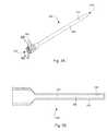
- a bone screw 100has two ends 102 and 104 connected by a shaft 106, and bone screw threads 110.
- the cut-out of FIG. 1reveals that bone screw 100 includes a hollow, cannulated portion 120, and one or more bone screw fenestrations 130 along the length of the cannulated portion 120.
- the cannulated portion 120e.g., lumen, hollow, chamber, etc.
- the longitudinal bore forming the cannulated portion of a bone screwmay be formed with a drilling operation (e.g., gun drilling).
- the fenestrations 130need not be even spaced along the cannulated portion 120, but may be arranged in a desired pattern or frequency along the length of the cannulated portion 120.
- the fenestrations 130may extend along a circumference of the bone screw 100 or may extend in a longitudinal direction along the length of the bone screw 100.
- one end 122 of the cannulated portion 120 of the bone screw 100is configured to accept a bone screw insert.
- the bone screw 100may comprise additional threads 140 on the one end 122 of the cannulated portion 120 to promote fixation of a bone screw insert.
- the cannulated portion 120 of the bone screw 100may be coaxial with the shaft 106 (e.g., with the longitudinal axis of the bore 124 being collinear with the longitudinal axis of the shaft 106) as shown in FIGS. 1 and 4 and the wall of the shaft 106 may be a consistent thickness about the circumference of the shaft 106 at any point along the length of the shaft 106 between the fist end 102 and the second end 104.
- the bone screwmay be a fixation screw used to hold two or more bones or bone pieces in a fixed spatial relationship with respect to each other.
- the bone screwmay be used to mend peripheral skeletal fractures or osteotomies, repair a spondyloysis or an odontoid fracture, or fuse lumbar facet joints, for example.
- Other beneficial uses of bone screws, and more particularly, fixation screws,will be known to one skilled in the art and are to be included within the scope of this application.
- the bone screw 100may include any material suitable for placement into a bone without harmful effects on the patient.
- suitable materialsinclude, but are not limited to, titanium and its alloys, tantalum and its alloys, nickel-cadmium and its alloys, steel and its alloys, plastics, absorbable materials, resorbable materials, polyamino acids, polylactide, polyglycolide, hydroxylapatite, and tricalciumphosphate.
- Other materials useful for bone screw constructionwill be known to those skilled in the art.
- Bone 200may, for example, be a human hip bone.
- bone screw 100is disposed within bone 200 by rotating the bone screw 100 such that the bone screw threads 110 act to pull bone screw 100 into bone 200, thereby anchoring bone screw 100 into place.
- an insert 300includes a cannulated portion 310 with a hollow cavity 320 surrounded by an insert wall 330, where the cavity and wall dimensions may be suitably chosen in order to carry out the practice of the concepts disclosed herein.
- the insertmay include a single piece, as disclosed in FIGS. 3A and 3B .
- the insertincludes two ends, 302 and 304, connected by a shaft 306.
- the insertmay include two or more pieces or sections that, when taken together, form the insert.
- the shaftmay be cannulated along its entire length, creating openings at each end of the insert.
- the cannulationmay extend only partially into the shaft so long as the cannulation is sufficient to allow for delivery of a substance from one end of the insert to one or more bone screw fenestrations.
- One end 302 of the insert 300may include threads 340 which interlock with bone screw threads 140 of FIG. 1 to help fix an insert 300 into a bone screw 100.
- the insertincludes two or more pieces or sections, only one of the sections need be cannulated such that the insert sections, when taken together, allow for delivery of a substance from one end of the insert to one or more bone screw fenestrations.
- the insert 300is cannulated and has a single passage or fenestration 308 for communication of fluids.
- the insertmay include multiple insert fenestrations.
- An insert having an appropriate number, size, shape, and location of insert fenestrationscan be chosen by the practitioner to provide a delivery pathway between at least one end of the insert and the one or more bone screw fenestrations.
- the insert 300may include a plurality of insert fenestrations 308 having a substantially rectangular cross-section.
- the delivery pathwaymay initiate at one end of the bone screw and pass through the insert to one or more bone screw fenestrations.
- the insert fenestrationsneed not match the bone screw fenestrations in number, size, shape, or location, although it may be advantageous to locate at least one of the insert fenestrations such that it may be substantially aligned with at least one bone screw fenestrations once both the bone screw and the insert are in place.
- Various embodiments of the insert and related bone screwsare shown in US-A-2012041395 titled "Method and Device for Delivering Medicine to Bone," filed September 7, 2011.
- fluidmay be communicated through a portion of the wall 330 that is permeable to the substance to be delivered such that the substance is delivered to the exterior of the insert by diffusion through the insert wall or through small openings in the insert wall.
- openingsmay be intentionally created such as by increasing the porosity of the insert material (e.g., by introducing a series of pinpricks into the material), or they may exist naturally as pores in the material.
- the insertmay or may not be fenestrated so long as delivery of the desired substance is not completely impeded by the insert.
- An embodiment including a permeable but non-fenestrated insertmay be preferred when it is desired to effect a controlled, slow release of the desired substance to a bone, or when it is desired to prevent bone fragments, blood, fat or other materials or fluids from traveling from the exterior of the insert to the interior cavity.
- the insert 300is cannulated and has a single passage for communication of fluids
- the insertmay include a second conduit for suction of fluids after irrigation.
- one passagemay provide fluid while the other passage concurrently removes fluid.
- the insertmay be removed and a bone screw may then be inserted into the irrigated opening in the bone.
- the same insert or another insertmay then be inserted into bone screw to deliver medications or other fluids.
- Such a processmay be particularly beneficial for treating open long-bone fractures.
- the exterior dimensions of the insert 300are only slightly smaller than the interior dimensions of the cannulated bone screw 100 to provide for a tight but sliding fit when the insert 300 is placed into the bone screw 100, as depicted in FIG. 4 in which the insert 300 is shown partially disposed within the bone screw 100.
- an insert cap 400which can be used to substantially seal the one end 302 of the insert 300 via insert cap threads 402 either before, during, or after the bone screw 100 and insert 300 are put into place.
- the insert 300may have substantially the same cross-sectional shape as the cannulated portion 120 of the bone screw 100, or their cross-sectional shapes may be different.
- the internal bone screw cavity and the exterior surface of the insertmay have a substantially circular cross-section.
- the insertmay be rotated with respect to the screw to achieve alignment of certain of the insert and bone screw fenestrations, for example.
- the insert and bone screwmay have substantially non-circular cross-sections such that the insert is not free to rotate once it has been disposed within the bone screw.
- at least part of the insert cross-sectionmay not match that of the bone screw cavity such that when the insert is disposed within the bone screw, one or more channels are formed longitudinally along at least part of the insert and bone screw shafts. Such channels may be useful, for example, to allow air or fluids to escape the bone screw cavity as the insert is introduced.
- the inserts described hereinmay be formed of any material compatible with the bone screw and able to be placed within the bone screw without producing adverse effects to the patient.
- suitable insert materialsinclude, but are not limited to, titanium and its alloys, tantalum and its alloys, nickel-cadmium and its alloys, steel and its alloys, plastics, absorbable materials, resorbable materials, polyamino acids, polylactide, polyglycolide, hydroxylapatite, and tricalciumphosphate.
- Other materials useful for insert constructionwill be known to those skilled in the art.
- the insertincludes two or more sections, the sections need not be formed of the same material.
- one or more of the insert sectionsmay be formed of a material specifically chosen to impart the desired level of permeability to the insert.
- a bone screw 500has an off-center cannulated portion.
- the bone screw 500has two ends 502 and 504 connected by a shaft 506, and bone screw threads 510.
- the bone screw 500further includes a hollow, cannulated portion 520, and one or more bone screw fenestrations 530 along the length of the cannulated portion 520.
- the fenestrations 530may be provided on only one side of the bone screw 500.
- the fenestrations 530provide an opening or passage between the hollow cannulated portion 520 of the bone screw 500 the exterior of the bone screw 500.
- the cannulated portion 520is be formed by a longitudinal bore 524 (e.g., hollow, chamber, etc.) through the shaft 506.
- the longitudinal axis 522 of the bore 524is offset from and parallel to the longitudinal axis 508 of the shaft 506, such that the cannulated portion 520 is not coaxial with the shaft 506.
- the wall of the shaft 506 surrounding the hollow cannulated portion 520therefore has a thickness that varies about the circumference of the shaft 506 with a thicker first wall portion 526 and a thinner second wall portion 528. As shown in FIGS.
- the fenestrations 530are provided in the first wall portion 526 with the increased thickness of the first wall portion 526 adding strength to the shaft 506 to compensate for the reduction in strength introduced by the fenestrations 530.
- the fenestrations 530may be provided in the second wall portion 528.
- a bone screw 600has an angled cannulated portion.
- the bone screw 600has two ends 602 and 604 connected by a shaft 606, and bone screw threads 610.
- the bone screw 600further includes a hollow, cannulated portion 620, and one or more bone screw fenestrations 630 along the length of the cannulated portion 620.
- the cannulated portion 620is formed by a longitudinal bore 624 (e.g., hollow, chamber, etc.) through the shaft 606.
- the longitudinal axis 622 of the bore 624is oriented relative to the longitudinal axis 608 of the shaft 606, such that the cannulated portion 620 is not coaxial with the shaft 606.
- the longitudinal axis 622 of the bore 624is angled relative to the longitudinal axis 608 of the shaft 606.
- the wall of the shaft 606 surrounding the hollow cannulated portion 620therefore has a thickness that varies about the circumference of the shaft 606 with a first wall portion 626 and a second wall portion 628. Because the bore 624 is angled, the thickness of the first wall portion 626 and the second wall portion 628 each vary along the length of the shaft 606.
- a bone screw 700may include fenestrations 730 having edges (e.g. sharpened or tapered sides), shown as edge 750 in various embodiments in FIGS. 7A-7E .
- edgese.g. sharpened or tapered sides
- edge 750is configured to assist in removing the bone screw 700 from the bone 200 by cutting through growth 202 in or proximate to the fenestration 730.
- the edge 750may be formed by the exterior surface 752 of the screw 700 and a surface 754 of the fenestration 730.
- the fenestration 730may be a slot extending along a circumference of the bone screw 700 and the fenestration surface 752 may be at an acute angle relative to the exterior surface 754 (see FIG. 7A ).
- the edge 750may be formed inside the fenestration 730 between a first surface 756 extending from the hollow cannulated portion of the bone screw 700 and a second surface 758 extending from the exterior of the bone screw 700 (see FIG. 7B ).
- the edge 750may protrude past the exterior of the bone screw 700 (see FIG. 7C ) or the edge 750 may protrude into the hollow cannulated portion of the bone screw 700 (see FIG. 7D ).
- the fenestration 730may be a slot extending longitudinally along a length of the bone screw 700 and the sharpened edge may be an edge 760 on the end of the fenestration 730 closest to a tip of the bone screw 700.
- the sharpened edgemay be an edge 762 of a fenestration 730 oriented in a longitudinal direction along the length of the bone screw 700.
- edges 750are shown in FIGS. 7A-7E as being generally planar surfaces, in other embodiments, one or both of the surfaces may be otherwise contoured.
- surface 754, surface 756, or surface 758may all be curved (e.g., concave) surfaces in other contemplated embodiments.
- the fenestrations 730 having the edges 750are shown as being formed in a threaded bone screw, in other contemplated embodiments, the fenestrations 730 including the edges 750 may be formed in threadless fasteners (e.g., nails, tacks, pins, etc.).
- a method 800 of administering a substance to a boneis shown.
- First a cannulated, fenestrated bone screwis introduced (e.g., implanted) into a bone (step 802).
- a cannulated insertis then inserted into the hollow portion of the bone screw (step 804).
- a substancesuch as a medication is then delivered into the cannulated portion of the insert so that the substance is delivered through the bone screw and to the bone (step 806).
- This sequencemight be preferred in order to shorten the overall surgery time, or to reduce the amount of material that enters the bone screw fenestrations from outside the screw during screw insertion, for example. Alternately, other circumstances may make it more advantageous to introduce the insert into the bone screw, in its entirety or only partially, after the bone screw is introduced into the bone. This latter sequence might be preferred in order to determine which screw fenestrations or exterior insert attachment mechanisms (e.g. grooves) are located at the optimum location for delivery of the desired substance, and thus what insert configuration or length should be used to facilitate substance delivery to desired locations in or near a bone.
- screw fenestrations or exterior insert attachment mechanismse.g. grooves
- sequencescan be envisioned by one skilled in the art, such as for example, partially introducing the bone screw into a bone, partially or completely inserting the insert into or along the bone screw, and then completing the insertion of the bone screw into the bone. Even more sequence variations are possible when one considers the additional step of introducing the substance into the cannulated portion of the bone screw insert.
- the insertmay be removed from the bone screw after use.
- the insertmay be utilized for facilitating the delivery of a substance such as a drug to a portion of the bone adjacent to the bone screw and the method 800 may further include removing the insert from the bone screw (step 808).
- An occluding shaftmay then be inserted into the hollow portion of the bone screw (step 809).
- an occluding shaft 900is similar in shape and size to the insert 300 but is instead a solid body or a hollow body lacking any fenestrations or other openings.
- the occluding shaft 900is instead configured to obstruct the fenestrations 130 in the bone screw 100 to retain the medication or other substance in or around the bone and seal the open end of the bone screw 100.
- the occluding shaft 900may extend the entire length of the hollow portion of the screw 100 or may only extend along a portion of the length of the hollow portion of the bone screw 100, forming a reservoir or cavity at the distal end of the hollow portion.
- One end of the occluding shaft 900may include external threads 940 similar to threads 340 of the insert 300 that are configured to engage threads 140 in the bone screw 100.
- the insertmay not be removed from the bone screw and an occluding shaft may be placed in the hollow cannulated portion of the insert.
- the occluding shaftmay therefore be sized to occupy the hollow portion of the insert and may extend the entire length of the hollow portion of the insert or may only extend along a portion of the length of the hollow portion of the insert, forming a reservoir or cavity at the distal end of the hollow portion.
- One end of the occluding shaftmay include external threads that are configured to engage internal threads in the insert.
- the occluding shaftmay be formed of any material compatible with the bone screw and able to be placed within the bone screw without producing adverse effects to the patient.
- suitable materialsinclude, but are not limited to, titanium and its alloys, tantalum and its alloys, nickel-cadmium and its alloys, steel and its alloys, plastics, absorbable materials, resorbable materials, polyamino acids, polylactide, polyglycolide, hydroxylapatite, and tricalciumphosphate.
- Other materials useful for construction of the occluding shaftwill be known to those skilled in the art.
- the bone screw, insert, and occluding shaftmay be sold or otherwise provided in a kit containing two or more inserts having different fenestrations or permeability characteristics.
- the availability of such a kithas the advantage of allowing a practitioner to select an appropriate insert based on the particular needs of the patient and including an appropriately sized occluding shaft.
Landscapes
- Health & Medical Sciences (AREA)
- Orthopedic Medicine & Surgery (AREA)
- Life Sciences & Earth Sciences (AREA)
- Surgery (AREA)
- General Health & Medical Sciences (AREA)
- Neurology (AREA)
- Veterinary Medicine (AREA)
- Engineering & Computer Science (AREA)
- Biomedical Technology (AREA)
- Heart & Thoracic Surgery (AREA)
- Public Health (AREA)
- Animal Behavior & Ethology (AREA)
- Molecular Biology (AREA)
- Medical Informatics (AREA)
- Nuclear Medicine, Radiotherapy & Molecular Imaging (AREA)
- Cardiology (AREA)
- Oral & Maxillofacial Surgery (AREA)
- Transplantation (AREA)
- Vascular Medicine (AREA)
- Surgical Instruments (AREA)
- Prostheses (AREA)
Description
- The present invention relates to devices for delivering substances such as medicants to bones. More particularly, the present invention concerns devices and related methods for delivering substances to the interior or exterior of fractured or otherwise injured bones, especially to the fracture interface.
- Delivery of medicants or therapeutics to bones is an often desirable but difficult-to-achieve process, especially if one desires to focus the delivery to the interior of a bone or to a particular area in a bone, see for example
US-A-2010/262089 . Delivery pins or needles are sometimes used to deliver medication or other fluids into bone. Such pins are typically made of metals such as titanium or steel, and must be fabricated ahead of time for later use. Thus, it is difficult to customize the pins for directing the delivery of medicants or fluids to a specific area of interest within a bone. Moreover, such pins do not serve as fixation screws for holding two or more bones or bone pieces in a fixed spatial relationship with respect to each other. - Bone screws can be used to repair or strengthen fractured or otherwise damaged or diseased bones, often by fixing two or more bones or bone pieces with respect to each other, in which case the bone screw may be referred to as a fixation screw. Such screws have been adapted to deliver liquids such as bone cements to the interior of a bone. These devices must be fabricated ahead of time for later use, thereby substantially limiting the ability to customize the device to the needs of an individual patient. Moreover, while these devices may be suitable for the one-time delivery of a curable substance such as a bone cement, they provide no way to control or regulate the amount of substance delivered. Substance delivery also cannot be directed to certain areas within the bone and not others without changing the location or configuration of the bone screw itself.
- One embodiment of the invention relates to a bone screw including a shaft having a wall, a cannulated portion disposed inside the shaft, and a fenestration in the shaft connecting the cannulated portion to an exterior of the bone screw. The cannulated portion is not coaxial with the shaft such that the wall includes a first wall portion having a different thickness than a second wall portion.
- It is to be understood that both the foregoing general description and the following detailed description are exemplary and explanatory only, and are not restrictive of the invention as claimed.
- Features, aspects, and advantages of the present invention will become apparent from the following description, appended claims, and the accompanying exemplary embodiments shown in the drawings, which are briefly described below.
FIG. 1 is a perspective view of a bone screw, in accordance with an exemplary embodiment.FIG. 2 is a perspective view of the bone screw ofFIG. 1 inserted into the hip bone of a patient.FIG. 3A is a perspective view of a bone screw insert with a single fenestration, in accordance with an example.FIG. 3B is a schematic cross-sectional view of the bone screw insert ofFIG. 3A .FIG. 4 is a perspective view of a bone screw, a bone screw insert, and an insert cap, in accordance with an example.FIG. 5A is a perspective of a bone screw with an off-center cannulated portion, in accordance with an embodiment of the invention.FIG. 5B is a schematic cross-sectional view of the bone screw ofFIG. 5A .FIG. 6A is a perspective of a bone screw with an angled cannulated portion, in accordance with an embodiment of the invention.FIG. 6B is a schematic cross-sectional view of the bone screw ofFIG. 6A .FIG. 7A is a detail schematic cross-sectional view of a fenestration for a bone screw with a sharpened edge, in accordance with an exemplary embodiment.FIG. 7B is a detail schematic cross-sectional view of a fenestration for a bone screw with a sharpened edge, in accordance with another exemplary embodiment.FIG. 7C is a detail schematic cross-sectional view of a fenestration for a bone screw with a sharpened edge, in accordance with another exemplary embodiment.FIG. 7D is a detail schematic cross-sectional view of a fenestration for a bone screw with a sharpened edge, in accordance with another exemplary embodiment.FIG. 7E is a detail schematic cross-sectional view of a fenestration for a bone screw with a sharpened edge, in accordance with another exemplary embodiment.FIG. 8 is a flowchart of a method for utilizing a bone screw and bone screw insert to deliver a medication.FIG. 9 is a perspective view of a bone screw and an occluding shaft, in accordance with an example.- For the purposes of this description, the term "cannulated" means that the described device or component (e.g., screw or insert) includes a hollow cavity disposed inside at least part of its shaft. For example, the cavity may consist of a bore beginning at or near one end of the screw or insert and extending longitudinally into the screw or insert. Other configurations are possible, however, and the hollow cavity need not be restricted to a cylindrical shape or a circular cross-section. The cavity may extend throughout the entire length of the screw or insert, thus creating openings at each end of the screw or insert, or alternatively, the cavity may extend only partially into the interior of the screw or insert. The shape and size of the cavity may be suitably chosen to allow delivery of the desired substance through the screw or insert to the bone area of interest. When it is desired to use the cannulated portion of the screw or insert as reservoir for the substance to be delivered, for example, the cavity may be made as large as possible so long as the screw and insert maintain the structural integrity needed for introduction into the bone.
- For the purposes of this description, the term "fenestration" is used broadly to include any slot, gap, or perforation that defines an opening between the inside of the cannulated portion of the screw or insert to the outside of the screw or insert whereby a desired substance may be delivered. Thus, a fenestrated screw includes an opening which defines a substance delivery pathway between the internal cannulated portion and the exterior of the screw. Likewise, a fenestrated insert is one that includes an opening which defines a substance delivery pathway between the internal cannulated portion and the exterior of the insert. In certain embodiments of the present invention where a fenestrated insert is utilized in combination with a fenestrated screw, at least one screw fenestration and at least one insert fenestration may be designed to align with each other once the screw and insert are in their appropriate configuration and position. Alignment or coordination of an insert fenestration and a screw fenestration will define a substance delivery pathway between the internal cannulated portion of the insert and the exterior of the screw.
- For the purposes of this description, the term "bone screw" is intended to refer to screws of all types which are presently known or hereafter devised for implantation into bone. In this regard, cancellous screws, cortical screws, and machine screws are all contemplated as being within the scope of the types of screws useful in the practice of selected embodiments of the present invention. The bone screws described herein will typically include threads along at least a portion of the exterior of the screw shaft, but it should be appreciated that tacks, pins, nails and the like may also be included within the definition of a bone screw for the purposes of this description, whether threaded or unthreaded. When threads are present, it may be found advantageous to use self-tapping threads, or alternatively, the threads can be pre-cut in the bone prior to bone screw insertion.
- Referring now to
FIG. 1 , in accordance with an exemplary embodiment, abone screw 100 has twoends shaft 106, andbone screw threads 110. The cut-out ofFIG. 1 reveals thatbone screw 100 includes a hollow, cannulatedportion 120, and one or more bone screwfenestrations 130 along the length of the cannulatedportion 120. The cannulated portion 120 (e.g., lumen, hollow, chamber, etc.) may be formed by alongitudinal bore 124 through theshaft 106. The longitudinal bore forming the cannulated portion of a bone screw may be formed with a drilling operation (e.g., gun drilling). - It will be appreciated by one skilled in the art that the
fenestrations 130 need not be even spaced along the cannulatedportion 120, but may be arranged in a desired pattern or frequency along the length of the cannulatedportion 120. Thefenestrations 130 may extend along a circumference of thebone screw 100 or may extend in a longitudinal direction along the length of thebone screw 100. It will be further appreciated by one skilled in the art that oneend 122 of the cannulatedportion 120 of thebone screw 100 is configured to accept a bone screw insert. For example, thebone screw 100 may compriseadditional threads 140 on the oneend 122 of the cannulatedportion 120 to promote fixation of a bone screw insert. - The cannulated
portion 120 of thebone screw 100 may be coaxial with the shaft 106 (e.g., with the longitudinal axis of thebore 124 being collinear with the longitudinal axis of the shaft 106) as shown inFIGS. 1 and4 and the wall of theshaft 106 may be a consistent thickness about the circumference of theshaft 106 at any point along the length of theshaft 106 between thefist end 102 and thesecond end 104. - In one embodiment, the bone screw may be a fixation screw used to hold two or more bones or bone pieces in a fixed spatial relationship with respect to each other. The bone screw may be used to mend peripheral skeletal fractures or osteotomies, repair a spondyloysis or an odontoid fracture, or fuse lumbar facet joints, for example. Other beneficial uses of bone screws, and more particularly, fixation screws, will be known to one skilled in the art and are to be included within the scope of this application.
- The
bone screw 100 may include any material suitable for placement into a bone without harmful effects on the patient. Examples of suitable materials include, but are not limited to, titanium and its alloys, tantalum and its alloys, nickel-cadmium and its alloys, steel and its alloys, plastics, absorbable materials, resorbable materials, polyamino acids, polylactide, polyglycolide, hydroxylapatite, and tricalciumphosphate. Other materials useful for bone screw construction will be known to those skilled in the art. - Referring now to
FIG. 2 , abone screw 100 is shown disposed partially within abone 200.Bone 200 may, for example, be a human hip bone. In one embodiment,bone screw 100 is disposed withinbone 200 by rotating thebone screw 100 such that thebone screw threads 110 act to pullbone screw 100 intobone 200, thereby anchoringbone screw 100 into place. - For the purposes of this description, the term "insert" is used to refer to one or more cannulated members which are disposed within the cannulated portion of a bone screw. Referring now to
FIGS. 3A and 3B , in accordance with an exemplary embodiment, aninsert 300 includes a cannulatedportion 310 with ahollow cavity 320 surrounded by aninsert wall 330, where the cavity and wall dimensions may be suitably chosen in order to carry out the practice of the concepts disclosed herein. In certain embodiments, the insert may include a single piece, as disclosed inFIGS. 3A and 3B . When theinsert 300 is a single piece, the insert includes two ends, 302 and 304, connected by ashaft 306. Alternatively, the insert may include two or more pieces or sections that, when taken together, form the insert. The shaft may be cannulated along its entire length, creating openings at each end of the insert. Alternatively, the cannulation may extend only partially into the shaft so long as the cannulation is sufficient to allow for delivery of a substance from one end of the insert to one or more bone screw fenestrations. Oneend 302 of theinsert 300 may includethreads 340 which interlock withbone screw threads 140 ofFIG. 1 to help fix aninsert 300 into abone screw 100. When the insert includes two or more pieces or sections, only one of the sections need be cannulated such that the insert sections, when taken together, allow for delivery of a substance from one end of the insert to one or more bone screw fenestrations. - In some embodiments disclosed herein, the
insert 300 is cannulated and has a single passage orfenestration 308 for communication of fluids. When substantially unimpeded delivery of a substance to one or more bone screw fenestrations is desired, the insert may include multiple insert fenestrations. An insert having an appropriate number, size, shape, and location of insert fenestrations can be chosen by the practitioner to provide a delivery pathway between at least one end of the insert and the one or more bone screw fenestrations. For example, theinsert 300 may include a plurality ofinsert fenestrations 308 having a substantially rectangular cross-section. Alternatively, the delivery pathway may initiate at one end of the bone screw and pass through the insert to one or more bone screw fenestrations. The insert fenestrations need not match the bone screw fenestrations in number, size, shape, or location, although it may be advantageous to locate at least one of the insert fenestrations such that it may be substantially aligned with at least one bone screw fenestrations once both the bone screw and the insert are in place. Various embodiments of the insert and related bone screws are shown inUS-A-2012041395 titled "Method and Device for Delivering Medicine to Bone," filed September 7, 2011. - Alternatively, fluid may be communicated through a portion of the
wall 330 that is permeable to the substance to be delivered such that the substance is delivered to the exterior of the insert by diffusion through the insert wall or through small openings in the insert wall. Such openings may be intentionally created such as by increasing the porosity of the insert material (e.g., by introducing a series of pinpricks into the material), or they may exist naturally as pores in the material. When the insert includes a material that is at least partially permeable to the substance to be delivered, the insert may or may not be fenestrated so long as delivery of the desired substance is not completely impeded by the insert. An embodiment including a permeable but non-fenestrated insert may be preferred when it is desired to effect a controlled, slow release of the desired substance to a bone, or when it is desired to prevent bone fragments, blood, fat or other materials or fluids from traveling from the exterior of the insert to the interior cavity. - While in some embodiments disclosed herein the
insert 300 is cannulated and has a single passage for communication of fluids, in other embodiments the insert may include a second conduit for suction of fluids after irrigation. As such, one passage may provide fluid while the other passage concurrently removes fluid. Following irrigation, the insert may be removed and a bone screw may then be inserted into the irrigated opening in the bone. The same insert or another insert, may then be inserted into bone screw to deliver medications or other fluids. Such a process may be particularly beneficial for treating open long-bone fractures. - In an example, the exterior dimensions of the
insert 300 are only slightly smaller than the interior dimensions of the cannulatedbone screw 100 to provide for a tight but sliding fit when theinsert 300 is placed into thebone screw 100, as depicted inFIG. 4 in which theinsert 300 is shown partially disposed within thebone screw 100. Also disclosed inFIG. 4 is aninsert cap 400 which can be used to substantially seal the oneend 302 of theinsert 300 viainsert cap threads 402 either before, during, or after thebone screw 100 and insert 300 are put into place. Theinsert 300 may have substantially the same cross-sectional shape as the cannulatedportion 120 of thebone screw 100, or their cross-sectional shapes may be different. For example, the internal bone screw cavity and the exterior surface of the insert may have a substantially circular cross-section. One advantage of this embodiment is that after the insert has been disposed within the bone screw, the insert may be rotated with respect to the screw to achieve alignment of certain of the insert and bone screw fenestrations, for example. In another embodiment, the insert and bone screw may have substantially non-circular cross-sections such that the insert is not free to rotate once it has been disposed within the bone screw. In yet another embodiment, at least part of the insert cross-section may not match that of the bone screw cavity such that when the insert is disposed within the bone screw, one or more channels are formed longitudinally along at least part of the insert and bone screw shafts. Such channels may be useful, for example, to allow air or fluids to escape the bone screw cavity as the insert is introduced. - The inserts described herein may be formed of any material compatible with the bone screw and able to be placed within the bone screw without producing adverse effects to the patient. Examples of suitable insert materials include, but are not limited to, titanium and its alloys, tantalum and its alloys, nickel-cadmium and its alloys, steel and its alloys, plastics, absorbable materials, resorbable materials, polyamino acids, polylactide, polyglycolide, hydroxylapatite, and tricalciumphosphate. Other materials useful for insert construction will be known to those skilled in the art. When the insert includes two or more sections, the sections need not be formed of the same material. In addition, when it is desired that the insert be permeable to the substance to be delivered, one or more of the insert sections may be formed of a material specifically chosen to impart the desired level of permeability to the insert.
- Referring now to
FIGS. 5A and 5B , in an embodiment of the invention, abone screw 500 has an off-center cannulated portion. Thebone screw 500 has twoends shaft 506, andbone screw threads 510. Thebone screw 500 further includes a hollow, cannulatedportion 520, and one or more bone screwfenestrations 530 along the length of the cannulatedportion 520. In one embodiment, thefenestrations 530 may be provided on only one side of thebone screw 500. Thefenestrations 530 provide an opening or passage between the hollow cannulatedportion 520 of thebone screw 500 the exterior of thebone screw 500. The cannulatedportion 520 is be formed by a longitudinal bore 524 (e.g., hollow, chamber, etc.) through theshaft 506. Thelongitudinal axis 522 of thebore 524 is offset from and parallel to thelongitudinal axis 508 of theshaft 506, such that the cannulatedportion 520 is not coaxial with theshaft 506. The wall of theshaft 506 surrounding the hollow cannulatedportion 520 therefore has a thickness that varies about the circumference of theshaft 506 with a thickerfirst wall portion 526 and a thinnersecond wall portion 528. As shown inFIGS. 5A and 5B , in one embodiment, thefenestrations 530 are provided in thefirst wall portion 526 with the increased thickness of thefirst wall portion 526 adding strength to theshaft 506 to compensate for the reduction in strength introduced by thefenestrations 530. However, in other embodiments, thefenestrations 530 may be provided in thesecond wall portion 528. - Referring now to
FIGS. 6A and 6B , in another embodiment of the invention, abone screw 600 has an angled cannulated portion. Thebone screw 600 has twoends shaft 606, andbone screw threads 610. Thebone screw 600 further includes a hollow, cannulatedportion 620, and one or more bone screwfenestrations 630 along the length of the cannulatedportion 620. The cannulatedportion 620 is formed by a longitudinal bore 624 (e.g., hollow, chamber, etc.) through theshaft 606. Thelongitudinal axis 622 of thebore 624 is oriented relative to thelongitudinal axis 608 of theshaft 606, such that the cannulatedportion 620 is not coaxial with theshaft 606. Further, thelongitudinal axis 622 of thebore 624 is angled relative to thelongitudinal axis 608 of theshaft 606. The wall of theshaft 606 surrounding the hollow cannulatedportion 620 therefore has a thickness that varies about the circumference of theshaft 606 with afirst wall portion 626 and asecond wall portion 628. Because thebore 624 is angled, the thickness of thefirst wall portion 626 and thesecond wall portion 628 each vary along the length of theshaft 606. - Referring now to
FIGS. 7A-7E , abone screw 700 may includefenestrations 730 having edges (e.g. sharpened or tapered sides), shown asedge 750 in various embodiments inFIGS. 7A-7E . As shown inFIG. 7A , during the period in which thebone screw 700 is inserted into abone 200, growth 202 of thebone 200 may intrude into the openings formed in the wall of thebone screw 700 by thefenestrations 730. Theedge 750 is configured to assist in removing thebone screw 700 from thebone 200 by cutting through growth 202 in or proximate to thefenestration 730. Theedge 750 may be formed by theexterior surface 752 of thescrew 700 and asurface 754 of thefenestration 730. Thefenestration 730 may be a slot extending along a circumference of thebone screw 700 and thefenestration surface 752 may be at an acute angle relative to the exterior surface 754 (seeFIG. 7A ). In another embodiment, theedge 750 may be formed inside thefenestration 730 between afirst surface 756 extending from the hollow cannulated portion of thebone screw 700 and asecond surface 758 extending from the exterior of the bone screw 700 (seeFIG. 7B ). In another embodiment, theedge 750 may protrude past the exterior of the bone screw 700 (seeFIG. 7C ) or theedge 750 may protrude into the hollow cannulated portion of the bone screw 700 (seeFIG. 7D ). - Referring to
FIG. 7E , in another embodiment, thefenestration 730 may be a slot extending longitudinally along a length of thebone screw 700 and the sharpened edge may be anedge 760 on the end of thefenestration 730 closest to a tip of thebone screw 700. In other contemplated embodiments, the sharpened edge may be anedge 762 of afenestration 730 oriented in a longitudinal direction along the length of thebone screw 700. - While the surfaces of the fenestration forming the
edge 750 are shown inFIGS. 7A-7E as being generally planar surfaces, in other embodiments, one or both of the surfaces may be otherwise contoured. For example,surface 754,surface 756, orsurface 758 may all be curved (e.g., concave) surfaces in other contemplated embodiments. - While the
fenestrations 730 having theedges 750 are shown as being formed in a threaded bone screw, in other contemplated embodiments, thefenestrations 730 including theedges 750 may be formed in threadless fasteners (e.g., nails, tacks, pins, etc.). - Referring now to
FIG. 8 , amethod 800 of administering a substance to a bone is shown. First a cannulated, fenestrated bone screw is introduced (e.g., implanted) into a bone (step 802). A cannulated insert is then inserted into the hollow portion of the bone screw (step 804). A substance such as a medication is then delivered into the cannulated portion of the insert so that the substance is delivered through the bone screw and to the bone (step 806). Under some circumstances, one may find it advantageous to introduce the insert into or along the bone screw, in its entirety or only partially, prior to introducing the bone screw into the bone. This sequence might be preferred in order to shorten the overall surgery time, or to reduce the amount of material that enters the bone screw fenestrations from outside the screw during screw insertion, for example. Alternately, other circumstances may make it more advantageous to introduce the insert into the bone screw, in its entirety or only partially, after the bone screw is introduced into the bone. This latter sequence might be preferred in order to determine which screw fenestrations or exterior insert attachment mechanisms (e.g. grooves) are located at the optimum location for delivery of the desired substance, and thus what insert configuration or length should be used to facilitate substance delivery to desired locations in or near a bone. Other sequences can be envisioned by one skilled in the art, such as for example, partially introducing the bone screw into a bone, partially or completely inserting the insert into or along the bone screw, and then completing the insertion of the bone screw into the bone. Even more sequence variations are possible when one considers the additional step of introducing the substance into the cannulated portion of the bone screw insert. - In certain procedures, the insert may be removed from the bone screw after use. For example, the insert may be utilized for facilitating the delivery of a substance such as a drug to a portion of the bone adjacent to the bone screw and the
method 800 may further include removing the insert from the bone screw (step 808). An occluding shaft may then be inserted into the hollow portion of the bone screw (step 809). - Referring to
FIG. 9 , in accordance with one example, an occludingshaft 900 is similar in shape and size to theinsert 300 but is instead a solid body or a hollow body lacking any fenestrations or other openings. The occludingshaft 900 is instead configured to obstruct thefenestrations 130 in thebone screw 100 to retain the medication or other substance in or around the bone and seal the open end of thebone screw 100. The occludingshaft 900 may extend the entire length of the hollow portion of thescrew 100 or may only extend along a portion of the length of the hollow portion of thebone screw 100, forming a reservoir or cavity at the distal end of the hollow portion. One end of the occludingshaft 900 may includeexternal threads 940 similar tothreads 340 of theinsert 300 that are configured to engagethreads 140 in thebone screw 100. - In another example, the insert may not be removed from the bone screw and an occluding shaft may be placed in the hollow cannulated portion of the insert. The occluding shaft may therefore be sized to occupy the hollow portion of the insert and may extend the entire length of the hollow portion of the insert or may only extend along a portion of the length of the hollow portion of the insert, forming a reservoir or cavity at the distal end of the hollow portion. One end of the occluding shaft may include external threads that are configured to engage internal threads in the insert.
- The occluding shaft may be formed of any material compatible with the bone screw and able to be placed within the bone screw without producing adverse effects to the patient. Examples of suitable materials include, but are not limited to, titanium and its alloys, tantalum and its alloys, nickel-cadmium and its alloys, steel and its alloys, plastics, absorbable materials, resorbable materials, polyamino acids, polylactide, polyglycolide, hydroxylapatite, and tricalciumphosphate. Other materials useful for construction of the occluding shaft will be known to those skilled in the art.
- The bone screw, insert, and occluding shaft may be sold or otherwise provided in a kit containing two or more inserts having different fenestrations or permeability characteristics. The availability of such a kit has the advantage of allowing a practitioner to select an appropriate insert based on the particular needs of the patient and including an appropriately sized occluding shaft.
- Further modifications and alternative embodiments will be apparent to those skilled in the art in view of this description. Accordingly, this description is to be construed as illustrative only. The construction and arrangements of the bone screws and inserts, as shown in the various exemplary embodiments, are illustrative only. Although only a few embodiments have been described in detail in this disclosure, many modifications are possible (e.g., variations in sizes, dimensions, structures, shapes and proportions of the various elements, values of parameters, mounting arrangements, use of materials, colors, orientations, etc.) without materially departing from the subject matter claimed. Some elements shown as integrally formed may be constructed of multiple parts or elements, the position of elements may be reversed or otherwise varied, and the nature or number of discrete elements or positions may be altered or varied. The order or sequence of any process, or method steps may also be varied. Other substitutions, modifications, changes and omissions may also be made in the design, operating conditions and arrangement of the various exemplary embodiments without departing from the scope of the claims.
Claims (8)
- A bone screw (500; 600), comprising:a shaft (506; 606) having a wall;a cannulated portion (520; 620) disposed inside the shaft (506; 606); anda fenestration (530; 630) in the shaft (506; 606) connecting the cannulated portion (520; 620) to an exterior of the bone screw (500; 600);characterised in that the cannulated portion (520; 620) is not coaxial with the shaft (506; 606), such that the wall includes a first wall portion (526; 626) having a different thickness than a second wall portion (528; 628).
- The bone screw (500) of claim 1, wherein the cannulated portion (520) has a longitudinal axis (522) that is offset from but parallel to the longitudinal axis (508) of the bone screw (500).
- The bone screw (600) of claim 1, wherein the cannulated portion (620) has a longitudinal axis (622) that is oriented at an angle to the longitudinal axis (608) of the bone screw (600).
- The bone screw (500; 600) of claim 1, further comprising an expanded end portion at a proximal end of the shaft (506; 606).
- The bone screw (500; 600) of claim 4, wherein the expanded end portion includes threads on an interior surface of the expanded end portion.
- The bone screw (500; 600) of claim 1, wherein an end of the cannulated portion (520; 620) coincides with an end of the bone screw (500; 600) to form an opening in the end of the bone screw (500; 600).
- The bone screw (500; 600) of claim 1, further comprising threads on an exterior of the bone screw (500; 600).
- The bone screw (500; 600) of claim 1, wherein the fenestration (530; 630) comprises a longitudinal slot formed along a length of the shaft (506; 606).
Priority Applications (1)
| Application Number | Priority Date | Filing Date | Title |
|---|---|---|---|
| EP16180626.0AEP3115009A1 (en) | 2012-08-07 | 2013-07-31 | Devices for delivery of medicine to bone |
Applications Claiming Priority (2)
| Application Number | Priority Date | Filing Date | Title |
|---|---|---|---|
| US13/569,062US9603644B2 (en) | 2012-08-07 | 2012-08-07 | Methods and devices for delivery of medicine to bone |
| PCT/US2013/052853WO2014025578A1 (en) | 2012-08-07 | 2013-07-31 | Devices for delivery of medicine to bone |
Related Child Applications (2)
| Application Number | Title | Priority Date | Filing Date |
|---|---|---|---|
| EP16180626.0ADivisionEP3115009A1 (en) | 2012-08-07 | 2013-07-31 | Devices for delivery of medicine to bone |
| EP16180626.0ADivision-IntoEP3115009A1 (en) | 2012-08-07 | 2013-07-31 | Devices for delivery of medicine to bone |
Publications (2)
| Publication Number | Publication Date |
|---|---|
| EP2882361A1 EP2882361A1 (en) | 2015-06-17 |
| EP2882361B1true EP2882361B1 (en) | 2016-09-21 |
Family
ID=48986229
Family Applications (2)
| Application Number | Title | Priority Date | Filing Date |
|---|---|---|---|
| EP13750196.1AActiveEP2882361B1 (en) | 2012-08-07 | 2013-07-31 | Devices for delivery of medicine to bone |
| EP16180626.0AWithdrawnEP3115009A1 (en) | 2012-08-07 | 2013-07-31 | Devices for delivery of medicine to bone |
Family Applications After (1)
| Application Number | Title | Priority Date | Filing Date |
|---|---|---|---|
| EP16180626.0AWithdrawnEP3115009A1 (en) | 2012-08-07 | 2013-07-31 | Devices for delivery of medicine to bone |
Country Status (4)
| Country | Link |
|---|---|
| US (1) | US9603644B2 (en) |
| EP (2) | EP2882361B1 (en) |
| CN (1) | CN104736083B (en) |
| WO (1) | WO2014025578A1 (en) |
Families Citing this family (33)
| Publication number | Priority date | Publication date | Assignee | Title |
|---|---|---|---|---|
| US20180228621A1 (en) | 2004-08-09 | 2018-08-16 | Mark A. Reiley | Apparatus, systems, and methods for the fixation or fusion of bone |
| JP5631597B2 (en) | 2007-03-12 | 2014-11-26 | スタウト メディカル グループ,エル.ピー. | Expandable mounting device and method |
| RU2712028C2 (en)* | 2009-11-09 | 2020-01-24 | Спайнуэлдинг Аг | Medical device for implantation into human or animal body or for strengthening of human or animal solid tissue for further implantation of separate implant and dental implant |
| US10363140B2 (en) | 2012-03-09 | 2019-07-30 | Si-Bone Inc. | Systems, device, and methods for joint fusion |
| US9044321B2 (en) | 2012-03-09 | 2015-06-02 | Si-Bone Inc. | Integrated implant |
| EP3818947B1 (en) | 2012-05-04 | 2023-08-30 | SI-Bone, Inc. | Fenestrated implant |
| WO2014145902A1 (en) | 2013-03-15 | 2014-09-18 | Si-Bone Inc. | Implants for spinal fixation or fusion |
| US11147688B2 (en) | 2013-10-15 | 2021-10-19 | Si-Bone Inc. | Implant placement |
| FR3024351B1 (en)* | 2014-08-01 | 2021-11-19 | Ldr Medical | BONE IMPLANTS |
| US10166033B2 (en) | 2014-09-18 | 2019-01-01 | Si-Bone Inc. | Implants for bone fixation or fusion |
| JP6542362B2 (en) | 2014-09-18 | 2019-07-10 | エスアイ−ボーン・インコーポレイテッドSi−Bone, Inc. | Matrix implant |
| US10363075B2 (en)* | 2015-02-09 | 2019-07-30 | Yingze Zhang | Porous bionic internal fixation device for promoting healing of fractured bone |
| US10052140B2 (en) | 2016-10-05 | 2018-08-21 | Stryker European Holdings I, Llc | Apparatus and method for fenestrated screw augmentation |
| CN106725793A (en)* | 2017-01-10 | 2017-05-31 | 河北医科大学第三医院 | A kind of intercondylar ridge internal fixation hollow screw of detachable taking-up |
| AU2018265427B2 (en) | 2017-05-12 | 2024-02-29 | Cutting Edge Spine Llc | Implants for tissue fixation and fusion |
| US10856922B2 (en)* | 2017-06-07 | 2020-12-08 | Warsaw Orthopedic, Inc. | Spinal implant system and method |
| CN107280756A (en)* | 2017-07-21 | 2017-10-24 | 西安康拓医疗技术有限公司 | A kind of medical cranial Bone nail structure |
| US11116519B2 (en) | 2017-09-26 | 2021-09-14 | Si-Bone Inc. | Systems and methods for decorticating the sacroiliac joint |
| US10888363B2 (en)* | 2017-12-06 | 2021-01-12 | Stout Medical Group, L.P. | Attachment device and method for use |
| ES3011907T3 (en) | 2018-03-28 | 2025-04-08 | Si Bone Inc | Threaded implants for use across bone segments |
| US11832860B2 (en) | 2018-06-22 | 2023-12-05 | University Of Virginia Patent Foundation | Bone fixation system for promoting the union of a bone fracture and fusion of bones across a joint space and related methods thereof |
| US11369419B2 (en) | 2019-02-14 | 2022-06-28 | Si-Bone Inc. | Implants for spinal fixation and or fusion |
| EP4613244A2 (en)* | 2019-02-14 | 2025-09-10 | SI-Bone Inc. | Implants for spinal fixation and or fusion |
| EP3808296B1 (en)* | 2019-10-17 | 2021-12-22 | Heraeus Medical GmbH | Device for local application of and / or for rinsing with fluids |
| JP7646654B2 (en) | 2019-11-21 | 2025-03-17 | エスアイ-ボーン・インコーポレイテッド | Rod coupling assembly for bone stabilization construct - Patent application |
| AU2020392121B2 (en) | 2019-11-27 | 2025-05-22 | Si-Bone, Inc. | Bone stabilizing implants and methods of placement across SI joints |
| EP4072452A4 (en) | 2019-12-09 | 2023-12-20 | SI-Bone, Inc. | Sacro-iliac joint stabilizing implants and methods of implantation |
| US11439432B2 (en) | 2020-04-09 | 2022-09-13 | Spinal Generations, Llc | Handle attachment for fluid delivery needle and method of use thereof |
| IT202000020551A1 (en)* | 2020-08-27 | 2022-02-27 | Rinaldo Giancola | DEVICE FOR THE SELECTIVE BIOLOGICAL SYNTHESIS OF A BONE TISSUE |
| CN112370133A (en)* | 2020-10-20 | 2021-02-19 | 广东施泰宝医疗科技有限公司 | Hollow spicule and matched tool thereof |
| EP4259015A4 (en) | 2020-12-09 | 2024-09-11 | SI-Bone, Inc. | SACROILIAC JOINT STABILIZATION IMPLANTS AND METHODS OF IMPLANTATION |
| US20240173146A1 (en)* | 2021-08-05 | 2024-05-30 | Surgentec, Llc | Methods, systems, and apparatuses for spinal fusion |
| WO2025038769A1 (en) | 2023-08-15 | 2025-02-20 | Si-Bone Inc. | Pelvic stabilization implants, methods of use and manufacture |
Family Cites Families (63)
| Publication number | Priority date | Publication date | Assignee | Title |
|---|---|---|---|---|
| US3310051A (en) | 1963-12-10 | 1967-03-21 | Rudolf R Schulte | Surgical reservoir for implantation beneath the skin |
| US4399814A (en) | 1981-04-27 | 1983-08-23 | Massachusetts Institute Of Technology | Method and apparatus for pressure-coated bones |
| US4464178A (en) | 1981-11-25 | 1984-08-07 | Dalton Michael J | Method and apparatus for administration of fluids |
| CA1227902A (en) | 1984-04-02 | 1987-10-13 | Raymond G. Tronzo | Fenestrated hip screw and method of augmented internal fixation |
| US4653487A (en) | 1986-01-29 | 1987-03-31 | Maale Gerhard E | Intramedullary rod assembly for cement injection system |
| US4760844A (en) | 1986-03-21 | 1988-08-02 | Ace Medical Company | Cannulated screw dye injector |
| US4772261A (en) | 1987-01-29 | 1988-09-20 | Board Of Regents, The University Of Texas System | Intramedullary catheter |
| EP0305417B1 (en) | 1987-02-20 | 1995-06-28 | DRAENERT, Klaus, Dr.med. | Suction drainage-bone screw |
| US5203770A (en) | 1990-04-20 | 1993-04-20 | Regents Of The University Of Minnesota | Method and apparatus for catheterization |
| US4976692A (en) | 1990-09-13 | 1990-12-11 | Travenol Laboratories (Israel) Ltd. | Catheter particularly useful for inducing labor and/or for the application of a pharmaceutical substance to the cervix of the uterus |
| US5122114A (en) | 1991-02-01 | 1992-06-16 | Board Of Regents, University Of Texas System | Method of using intramedullary catheter |
| JPH0596012A (en) | 1991-10-07 | 1993-04-20 | Olympus Optical Co Ltd | Thermotherapic device |
| US5332398A (en) | 1992-02-01 | 1994-07-26 | Board Of Regents, The University Of Texas System | Intramedullary catheter |
| US5433718A (en) | 1992-08-20 | 1995-07-18 | Brinker; Mark | Antibiotic eluding intramedullary nail apparatus |
| US5372583A (en) | 1992-11-25 | 1994-12-13 | Cardiopulmonary Specialities, Inc. | Bone marrow infuser and method of use |
| US5425723A (en) | 1993-12-30 | 1995-06-20 | Boston Scientific Corporation | Infusion catheter with uniform distribution of fluids |
| AU681761B2 (en) | 1994-02-15 | 1997-09-04 | Biosearch Italia S.P.A. | Central venous catheters loaded with antibiotics of the ramoplanin group preventing development of catheter related infections |
| US5702372A (en) | 1995-02-08 | 1997-12-30 | Medtronic, Inc. | Lined infusion catheter |
| US6077265A (en) | 1995-04-21 | 2000-06-20 | Werding; Gerd | Nail for fixing the position and shape of broken long bones |
| US5562625A (en) | 1995-05-02 | 1996-10-08 | Stefancin, Jr.; Ronald J. | Reusasble syringe with a disposable needle sheath |
| US5681289A (en) | 1995-08-14 | 1997-10-28 | Medicinelodge Inc. | Chemical dispensing system |
| US5749883A (en) | 1995-08-30 | 1998-05-12 | Halpern; David Marcos | Medical instrument |
| US5871484A (en) | 1995-11-09 | 1999-02-16 | General Orthopedics | Apparatus and method for administering a biologically active substance to a bone |
| US5800407A (en) | 1995-12-21 | 1998-09-01 | Eldor; Joseph | Multiple hole epidural catheter |
| US6783514B2 (en) | 1997-01-31 | 2004-08-31 | United States Surgical Corporation | Fibrin sealant applicator |
| US5951160A (en) | 1997-11-20 | 1999-09-14 | Biomet, Inc. | Method and apparatus for packaging, mixing and delivering bone cement |
| US6364856B1 (en) | 1998-04-14 | 2002-04-02 | Boston Scientific Corporation | Medical device with sponge coating for controlled drug release |
| US6461327B1 (en) | 1998-08-07 | 2002-10-08 | Embol-X, Inc. | Atrial isolator and method of use |
| US6214012B1 (en) | 1998-11-13 | 2001-04-10 | Harrington Arthritis Research Center | Method and apparatus for delivering material to a desired location |
| US6019761A (en) | 1998-12-23 | 2000-02-01 | Gustilo; Ramon B. | Intramedullary nail and method of use |
| US6210376B1 (en)* | 1999-04-08 | 2001-04-03 | New York University | Cannulated delivery pin |
| US6048343A (en) | 1999-06-02 | 2000-04-11 | Mathis; John M. | Bone screw system |
| US6220888B1 (en) | 1999-06-25 | 2001-04-24 | Hubbell Incorporated | Quick disconnect cable connector device with integral body and strain relief structure |
| US6387098B1 (en) | 1999-10-21 | 2002-05-14 | Peter Alexander Cole | Intramedullary catheter nail apparatus and method |
| US6929633B2 (en) | 2000-01-25 | 2005-08-16 | Bacchus Vascular, Inc. | Apparatus and methods for clot dissolution |
| US6565572B2 (en) | 2000-04-10 | 2003-05-20 | Sdgi Holdings, Inc. | Fenestrated surgical screw and method |
| US6821298B1 (en) | 2000-04-18 | 2004-11-23 | Roger P. Jackson | Anterior expandable spinal fusion cage system |
| US20020169507A1 (en) | 2000-12-14 | 2002-11-14 | David Malone | Interbody spine fusion cage |
| AUPR553701A0 (en) | 2001-06-07 | 2001-07-12 | Royal Alexandra Hospital For Children, The | A device for the delivery of a drug to a fractured bone |
| US6679890B2 (en) | 2001-08-28 | 2004-01-20 | Joseph Y. Margulies | Method and apparatus for augmentation of the femoral neck |
| US7488320B2 (en) | 2001-11-01 | 2009-02-10 | Renova Orthopedics, Llc | Orthopaedic implant fixation using an in-situ formed anchor |
| US6960215B2 (en) | 2002-05-08 | 2005-11-01 | Boston Scientific Scimed, Inc. | Tactical detachable anatomic containment device and therapeutic treatment system |
| US7354442B2 (en)* | 2003-05-05 | 2008-04-08 | Warsaw Orthopedic, Inc. | Bone anchor and methods of using the same |
| WO2005000090A2 (en) | 2003-05-30 | 2005-01-06 | Medi-Screw, Inc. | Medical implant systems |
| US8062270B2 (en) | 2003-07-15 | 2011-11-22 | Spinal Generations, Llc | Method and device for delivering medicine to bone |
| US7608062B2 (en) | 2003-07-15 | 2009-10-27 | Spinal Generations, Llc | Method and device for delivering medicine to bone |
| US7575572B2 (en) | 2003-07-15 | 2009-08-18 | Spinal Generations, Llc | Method and device for delivering medicine to bone |
| US7527611B2 (en) | 2003-07-15 | 2009-05-05 | Spinal Generations, Llc | Method and device for delivering medicine to bone |
| US8870836B2 (en)* | 2003-07-15 | 2014-10-28 | Spinal Generations, Llc | Method and device for delivering medicine to bone |
| US8070785B2 (en)* | 2003-09-16 | 2011-12-06 | Spineco, Inc. | Bone anchor prosthesis and system |
| CN101065080B (en) | 2004-07-30 | 2021-10-29 | 德普伊新特斯产品有限责任公司 | Materials and Instruments for Manipulating Bone and Other Tissues |
| ES2318391T3 (en)* | 2005-08-05 | 2009-05-01 | Biedermann Motech Gmbh | OSEO ANCHORAGE ELEMENT. |
| US8057090B1 (en) | 2005-08-31 | 2011-11-15 | Subrata Saha | Automated bone cement mixer |
| US20070233123A1 (en)* | 2006-02-21 | 2007-10-04 | Osteomed, L.P. | Bone fixation device |
| US20080154229A1 (en) | 2006-07-26 | 2008-06-26 | Lambert Systems, L.L.C. | Device And Method For Mixing And Delivering Bone Cement Precursors |
| TWM306498U (en) | 2006-08-10 | 2007-02-21 | Shih-Tseng Lee | Securing member, expansion anchroing screw set |
| FR2913876B1 (en) | 2007-03-20 | 2009-06-05 | Memometal Technologies Soc Par | OSTEOSYNTHESIS DEVICE |
| US8740954B2 (en) | 2007-12-19 | 2014-06-03 | Integral Spine Solutions, Inc. | Device and method for orthopedic fracture fixation |
| US8974505B2 (en)* | 2008-06-16 | 2015-03-10 | Anna G. U. Sawa | Venting/pressure adjustment to aid in delivery of material into an anatomic region via a cannula |
| US20100042213A1 (en) | 2008-08-13 | 2010-02-18 | Nebosky Paul S | Drug delivery implants |
| JP5774989B2 (en) | 2008-08-13 | 2015-09-09 | スメド−ティーエイ/ティーディー・エルエルシー | Orthopedic screw |
| KR101687435B1 (en)* | 2009-07-06 | 2016-12-19 | 신세스 게엠바하 | Expandable fixation assemblies |
| WO2011063240A1 (en)* | 2009-11-20 | 2011-05-26 | Knee Creations, Llc | Implantable devices for subchondral treatment of joint pain |
- 2012
- 2012-08-07USUS13/569,062patent/US9603644B2/enactiveActive
- 2013
- 2013-07-31EPEP13750196.1Apatent/EP2882361B1/enactiveActive
- 2013-07-31CNCN201380040526.6Apatent/CN104736083B/ennot_activeExpired - Fee Related
- 2013-07-31WOPCT/US2013/052853patent/WO2014025578A1/enactiveApplication Filing
- 2013-07-31EPEP16180626.0Apatent/EP3115009A1/ennot_activeWithdrawn
Also Published As
| Publication number | Publication date |
|---|---|
| EP2882361A1 (en) | 2015-06-17 |
| CN104736083B (en) | 2018-03-27 |
| US20140046379A1 (en) | 2014-02-13 |
| WO2014025578A1 (en) | 2014-02-13 |
| US9603644B2 (en) | 2017-03-28 |
| EP3115009A1 (en) | 2017-01-11 |
| CN104736083A (en) | 2015-06-24 |
Similar Documents
| Publication | Publication Date | Title |
|---|---|---|
| EP2882361B1 (en) | Devices for delivery of medicine to bone | |
| US7527611B2 (en) | Method and device for delivering medicine to bone | |
| US7575572B2 (en) | Method and device for delivering medicine to bone | |
| US7608062B2 (en) | Method and device for delivering medicine to bone | |
| US10188440B2 (en) | Method and device for delivering medicine to bone | |
| ES2964578T3 (en) | Fenestrated implant | |
| TWI698219B (en) | Bone fixation element | |
| US20110196372A1 (en) | Bone Fixing Material and Thighbone Fixing System | |
| US9510841B2 (en) | Drill bit and method for preparing a bone for a fixation screw | |
| JP2007511324A (en) | Windowed bone tap and method | |
| JP2018516729A (en) | Bone fixation implant system | |
| JP2017527410A (en) | Bone fixation implants and means of fixation | |
| US10258381B2 (en) | Conical end cap for intramedullary nail |
Legal Events
| Date | Code | Title | Description |
|---|---|---|---|
| PUAI | Public reference made under article 153(3) epc to a published international application that has entered the european phase | Free format text:ORIGINAL CODE: 0009012 | |
| 17P | Request for examination filed | Effective date:20150205 | |
| AK | Designated contracting states | Kind code of ref document:A1 Designated state(s):AL AT BE BG CH CY CZ DE DK EE ES FI FR GB GR HR HU IE IS IT LI LT LU LV MC MK MT NL NO PL PT RO RS SE SI SK SM TR | |
| AX | Request for extension of the european patent | Extension state:BA ME | |
| DAX | Request for extension of the european patent (deleted) | ||
| GRAP | Despatch of communication of intention to grant a patent | Free format text:ORIGINAL CODE: EPIDOSNIGR1 | |
| INTG | Intention to grant announced | Effective date:20160420 | |
| RAP1 | Party data changed (applicant data changed or rights of an application transferred) | Owner name:SPINAL GENERATIONS, LLC | |
| GRAS | Grant fee paid | Free format text:ORIGINAL CODE: EPIDOSNIGR3 | |
| GRAA | (expected) grant | Free format text:ORIGINAL CODE: 0009210 | |
| AK | Designated contracting states | Kind code of ref document:B1 Designated state(s):AL AT BE BG CH CY CZ DE DK EE ES FI FR GB GR HR HU IE IS IT LI LT LU LV MC MK MT NL NO PL PT RO RS SE SI SK SM TR | |
| REG | Reference to a national code | Ref country code:GB Ref legal event code:FG4D | |
| REG | Reference to a national code | Ref country code:CH Ref legal event code:EP | |
| REG | Reference to a national code | Ref country code:AT Ref legal event code:REF Ref document number:830404 Country of ref document:AT Kind code of ref document:T Effective date:20161015 | |
| REG | Reference to a national code | Ref country code:IE Ref legal event code:FG4D | |
| REG | Reference to a national code | Ref country code:DE Ref legal event code:R096 Ref document number:602013011881 Country of ref document:DE | |
| REG | Reference to a national code | Ref country code:LT Ref legal event code:MG4D Ref country code:NL Ref legal event code:MP Effective date:20160921 | |
| PG25 | Lapsed in a contracting state [announced via postgrant information from national office to epo] | Ref country code:FI Free format text:LAPSE BECAUSE OF FAILURE TO SUBMIT A TRANSLATION OF THE DESCRIPTION OR TO PAY THE FEE WITHIN THE PRESCRIBED TIME-LIMIT Effective date:20160921 Ref country code:LT Free format text:LAPSE BECAUSE OF FAILURE TO SUBMIT A TRANSLATION OF THE DESCRIPTION OR TO PAY THE FEE WITHIN THE PRESCRIBED TIME-LIMIT Effective date:20160921 Ref country code:NO Free format text:LAPSE BECAUSE OF FAILURE TO SUBMIT A TRANSLATION OF THE DESCRIPTION OR TO PAY THE FEE WITHIN THE PRESCRIBED TIME-LIMIT Effective date:20161221 Ref country code:RS Free format text:LAPSE BECAUSE OF FAILURE TO SUBMIT A TRANSLATION OF THE DESCRIPTION OR TO PAY THE FEE WITHIN THE PRESCRIBED TIME-LIMIT Effective date:20160921 | |
| REG | Reference to a national code | Ref country code:AT Ref legal event code:MK05 Ref document number:830404 Country of ref document:AT Kind code of ref document:T Effective date:20160921 | |
| PG25 | Lapsed in a contracting state [announced via postgrant information from national office to epo] | Ref country code:LV Free format text:LAPSE BECAUSE OF FAILURE TO SUBMIT A TRANSLATION OF THE DESCRIPTION OR TO PAY THE FEE WITHIN THE PRESCRIBED TIME-LIMIT Effective date:20160921 Ref country code:GR Free format text:LAPSE BECAUSE OF FAILURE TO SUBMIT A TRANSLATION OF THE DESCRIPTION OR TO PAY THE FEE WITHIN THE PRESCRIBED TIME-LIMIT Effective date:20161222 Ref country code:NL Free format text:LAPSE BECAUSE OF FAILURE TO SUBMIT A TRANSLATION OF THE DESCRIPTION OR TO PAY THE FEE WITHIN THE PRESCRIBED TIME-LIMIT Effective date:20160921 Ref country code:SE Free format text:LAPSE BECAUSE OF FAILURE TO SUBMIT A TRANSLATION OF THE DESCRIPTION OR TO PAY THE FEE WITHIN THE PRESCRIBED TIME-LIMIT Effective date:20160921 | |
| PG25 | Lapsed in a contracting state [announced via postgrant information from national office to epo] | Ref country code:RO Free format text:LAPSE BECAUSE OF FAILURE TO SUBMIT A TRANSLATION OF THE DESCRIPTION OR TO PAY THE FEE WITHIN THE PRESCRIBED TIME-LIMIT Effective date:20160921 Ref country code:EE Free format text:LAPSE BECAUSE OF FAILURE TO SUBMIT A TRANSLATION OF THE DESCRIPTION OR TO PAY THE FEE WITHIN THE PRESCRIBED TIME-LIMIT Effective date:20160921 | |
| PG25 | Lapsed in a contracting state [announced via postgrant information from national office to epo] | Ref country code:PT Free format text:LAPSE BECAUSE OF FAILURE TO SUBMIT A TRANSLATION OF THE DESCRIPTION OR TO PAY THE FEE WITHIN THE PRESCRIBED TIME-LIMIT Effective date:20170123 Ref country code:BE Free format text:LAPSE BECAUSE OF FAILURE TO SUBMIT A TRANSLATION OF THE DESCRIPTION OR TO PAY THE FEE WITHIN THE PRESCRIBED TIME-LIMIT Effective date:20160921 Ref country code:PL Free format text:LAPSE BECAUSE OF FAILURE TO SUBMIT A TRANSLATION OF THE DESCRIPTION OR TO PAY THE FEE WITHIN THE PRESCRIBED TIME-LIMIT Effective date:20160921 Ref country code:ES Free format text:LAPSE BECAUSE OF FAILURE TO SUBMIT A TRANSLATION OF THE DESCRIPTION OR TO PAY THE FEE WITHIN THE PRESCRIBED TIME-LIMIT Effective date:20160921 Ref country code:SK Free format text:LAPSE BECAUSE OF FAILURE TO SUBMIT A TRANSLATION OF THE DESCRIPTION OR TO PAY THE FEE WITHIN THE PRESCRIBED TIME-LIMIT Effective date:20160921 Ref country code:AT Free format text:LAPSE BECAUSE OF FAILURE TO SUBMIT A TRANSLATION OF THE DESCRIPTION OR TO PAY THE FEE WITHIN THE PRESCRIBED TIME-LIMIT Effective date:20160921 Ref country code:SM Free format text:LAPSE BECAUSE OF FAILURE TO SUBMIT A TRANSLATION OF THE DESCRIPTION OR TO PAY THE FEE WITHIN THE PRESCRIBED TIME-LIMIT Effective date:20160921 Ref country code:IS Free format text:LAPSE BECAUSE OF FAILURE TO SUBMIT A TRANSLATION OF THE DESCRIPTION OR TO PAY THE FEE WITHIN THE PRESCRIBED TIME-LIMIT Effective date:20170121 Ref country code:CZ Free format text:LAPSE BECAUSE OF FAILURE TO SUBMIT A TRANSLATION OF THE DESCRIPTION OR TO PAY THE FEE WITHIN THE PRESCRIBED TIME-LIMIT Effective date:20160921 Ref country code:BG Free format text:LAPSE BECAUSE OF FAILURE TO SUBMIT A TRANSLATION OF THE DESCRIPTION OR TO PAY THE FEE WITHIN THE PRESCRIBED TIME-LIMIT Effective date:20161221 | |
| REG | Reference to a national code | Ref country code:FR Ref legal event code:PLFP Year of fee payment:5 | |
| REG | Reference to a national code | Ref country code:DE Ref legal event code:R097 Ref document number:602013011881 Country of ref document:DE | |
| PG25 | Lapsed in a contracting state [announced via postgrant information from national office to epo] | Ref country code:IT Free format text:LAPSE BECAUSE OF FAILURE TO SUBMIT A TRANSLATION OF THE DESCRIPTION OR TO PAY THE FEE WITHIN THE PRESCRIBED TIME-LIMIT Effective date:20160921 | |
| PLBE | No opposition filed within time limit | Free format text:ORIGINAL CODE: 0009261 | |
| STAA | Information on the status of an ep patent application or granted ep patent | Free format text:STATUS: NO OPPOSITION FILED WITHIN TIME LIMIT | |
| PG25 | Lapsed in a contracting state [announced via postgrant information from national office to epo] | Ref country code:DK Free format text:LAPSE BECAUSE OF FAILURE TO SUBMIT A TRANSLATION OF THE DESCRIPTION OR TO PAY THE FEE WITHIN THE PRESCRIBED TIME-LIMIT Effective date:20160921 | |
| 26N | No opposition filed | Effective date:20170622 | |
| PG25 | Lapsed in a contracting state [announced via postgrant information from national office to epo] | Ref country code:SI Free format text:LAPSE BECAUSE OF FAILURE TO SUBMIT A TRANSLATION OF THE DESCRIPTION OR TO PAY THE FEE WITHIN THE PRESCRIBED TIME-LIMIT Effective date:20160921 | |
| REG | Reference to a national code | Ref country code:CH Ref legal event code:PL | |
| PG25 | Lapsed in a contracting state [announced via postgrant information from national office to epo] | Ref country code:LI Free format text:LAPSE BECAUSE OF NON-PAYMENT OF DUE FEES Effective date:20170731 Ref country code:CH Free format text:LAPSE BECAUSE OF NON-PAYMENT OF DUE FEES Effective date:20170731 | |
| REG | Reference to a national code | Ref country code:IE Ref legal event code:MM4A | |
| REG | Reference to a national code | Ref country code:FR Ref legal event code:PLFP Year of fee payment:6 | |
| PG25 | Lapsed in a contracting state [announced via postgrant information from national office to epo] | Ref country code:LU Free format text:LAPSE BECAUSE OF NON-PAYMENT OF DUE FEES Effective date:20170731 | |
| PG25 | Lapsed in a contracting state [announced via postgrant information from national office to epo] | Ref country code:IE Free format text:LAPSE BECAUSE OF NON-PAYMENT OF DUE FEES Effective date:20170731 | |
| PG25 | Lapsed in a contracting state [announced via postgrant information from national office to epo] | Ref country code:MT Free format text:LAPSE BECAUSE OF NON-PAYMENT OF DUE FEES Effective date:20170731 | |
| PG25 | Lapsed in a contracting state [announced via postgrant information from national office to epo] | Ref country code:AL Free format text:LAPSE BECAUSE OF FAILURE TO SUBMIT A TRANSLATION OF THE DESCRIPTION OR TO PAY THE FEE WITHIN THE PRESCRIBED TIME-LIMIT Effective date:20160921 | |
| PG25 | Lapsed in a contracting state [announced via postgrant information from national office to epo] | Ref country code:MC Free format text:LAPSE BECAUSE OF FAILURE TO SUBMIT A TRANSLATION OF THE DESCRIPTION OR TO PAY THE FEE WITHIN THE PRESCRIBED TIME-LIMIT Effective date:20160921 Ref country code:HU Free format text:LAPSE BECAUSE OF FAILURE TO SUBMIT A TRANSLATION OF THE DESCRIPTION OR TO PAY THE FEE WITHIN THE PRESCRIBED TIME-LIMIT; INVALID AB INITIO Effective date:20130731 | |
| PG25 | Lapsed in a contracting state [announced via postgrant information from national office to epo] | Ref country code:CY Free format text:LAPSE BECAUSE OF FAILURE TO SUBMIT A TRANSLATION OF THE DESCRIPTION OR TO PAY THE FEE WITHIN THE PRESCRIBED TIME-LIMIT Effective date:20160921 | |
| PG25 | Lapsed in a contracting state [announced via postgrant information from national office to epo] | Ref country code:MK Free format text:LAPSE BECAUSE OF FAILURE TO SUBMIT A TRANSLATION OF THE DESCRIPTION OR TO PAY THE FEE WITHIN THE PRESCRIBED TIME-LIMIT Effective date:20160921 | |
| PG25 | Lapsed in a contracting state [announced via postgrant information from national office to epo] | Ref country code:TR Free format text:LAPSE BECAUSE OF FAILURE TO SUBMIT A TRANSLATION OF THE DESCRIPTION OR TO PAY THE FEE WITHIN THE PRESCRIBED TIME-LIMIT Effective date:20160921 | |
| PG25 | Lapsed in a contracting state [announced via postgrant information from national office to epo] | Ref country code:HR Free format text:LAPSE BECAUSE OF FAILURE TO SUBMIT A TRANSLATION OF THE DESCRIPTION OR TO PAY THE FEE WITHIN THE PRESCRIBED TIME-LIMIT Effective date:20160921 | |
| P01 | Opt-out of the competence of the unified patent court (upc) registered | Effective date:20230427 | |
| PGFP | Annual fee paid to national office [announced via postgrant information from national office to epo] | Ref country code:DE Payment date:20240604 Year of fee payment:12 | |
| PGFP | Annual fee paid to national office [announced via postgrant information from national office to epo] | Ref country code:GB Payment date:20250612 Year of fee payment:13 | |
| PGFP | Annual fee paid to national office [announced via postgrant information from national office to epo] | Ref country code:FR Payment date:20250610 Year of fee payment:13 |