EP2879912B1 - System and method for controlling exterior vehicle lights responsive to detection of a semi-truck - Google Patents
System and method for controlling exterior vehicle lights responsive to detection of a semi-truckDownload PDFInfo
- Publication number
- EP2879912B1 EP2879912B1EP13826453.6AEP13826453AEP2879912B1EP 2879912 B1EP2879912 B1EP 2879912B1EP 13826453 AEP13826453 AEP 13826453AEP 2879912 B1EP2879912 B1EP 2879912B1
- Authority
- EP
- European Patent Office
- Prior art keywords
- semi
- truck
- oncoming
- lights
- controller
- Prior art date
- Legal status (The legal status is an assumption and is not a legal conclusion. Google has not performed a legal analysis and makes no representation as to the accuracy of the status listed.)
- Active
Links
Images


Classifications
- H—ELECTRICITY
- H04—ELECTRIC COMMUNICATION TECHNIQUE
- H04N—PICTORIAL COMMUNICATION, e.g. TELEVISION
- H04N7/00—Television systems
- H04N7/18—Closed-circuit television [CCTV] systems, i.e. systems in which the video signal is not broadcast
- G—PHYSICS
- G06—COMPUTING OR CALCULATING; COUNTING
- G06V—IMAGE OR VIDEO RECOGNITION OR UNDERSTANDING
- G06V20/00—Scenes; Scene-specific elements
- G06V20/50—Context or environment of the image
- G06V20/56—Context or environment of the image exterior to a vehicle by using sensors mounted on the vehicle
- G06V20/58—Recognition of moving objects or obstacles, e.g. vehicles or pedestrians; Recognition of traffic objects, e.g. traffic signs, traffic lights or roads
- G06V20/584—Recognition of moving objects or obstacles, e.g. vehicles or pedestrians; Recognition of traffic objects, e.g. traffic signs, traffic lights or roads of vehicle lights or traffic lights
- B—PERFORMING OPERATIONS; TRANSPORTING
- B60—VEHICLES IN GENERAL
- B60Q—ARRANGEMENT OF SIGNALLING OR LIGHTING DEVICES, THE MOUNTING OR SUPPORTING THEREOF OR CIRCUITS THEREFOR, FOR VEHICLES IN GENERAL
- B60Q1/00—Arrangement of optical signalling or lighting devices, the mounting or supporting thereof or circuits therefor
- B60Q1/02—Arrangement of optical signalling or lighting devices, the mounting or supporting thereof or circuits therefor the devices being primarily intended to illuminate the way ahead or to illuminate other areas of way or environments
- B60Q1/04—Arrangement of optical signalling or lighting devices, the mounting or supporting thereof or circuits therefor the devices being primarily intended to illuminate the way ahead or to illuminate other areas of way or environments the devices being headlights
- B60Q1/14—Arrangement of optical signalling or lighting devices, the mounting or supporting thereof or circuits therefor the devices being primarily intended to illuminate the way ahead or to illuminate other areas of way or environments the devices being headlights having dimming means
- B60Q1/1415—Dimming circuits
- B60Q1/1423—Automatic dimming circuits, i.e. switching between high beam and low beam due to change of ambient light or light level in road traffic
- B60Q1/143—Automatic dimming circuits, i.e. switching between high beam and low beam due to change of ambient light or light level in road traffic combined with another condition, e.g. using vehicle recognition from camera images or activation of wipers
- B—PERFORMING OPERATIONS; TRANSPORTING
- B60—VEHICLES IN GENERAL
- B60Q—ARRANGEMENT OF SIGNALLING OR LIGHTING DEVICES, THE MOUNTING OR SUPPORTING THEREOF OR CIRCUITS THEREFOR, FOR VEHICLES IN GENERAL
- B60Q2300/00—Indexing codes for automatically adjustable headlamps or automatically dimmable headlamps
- B60Q2300/40—Indexing codes relating to other road users or special conditions
- B60Q2300/42—Indexing codes relating to other road users or special conditions oncoming vehicle
Definitions
- the present inventiongenerally relates to a system and method for controlling exterior lights of a controlled vehicle, and more specifically relates to improvements in systems that control exterior lights of a controlled vehicle in response to the detection of other vehicles.
- Document 'A Monocular Vision Based Advancing Lighting Automation System for Driving Assistance' by J. Rebut et al.relates to a night time vehicle detection system performing automatic headlamp control in the frame work of driving assistance.
- image processingenables detecting vehicles and estimating their position in order to increase driver visibility by adjusting headlamps. Detecting light spots, tracking light spots, vehicle building, and position estimation are disclosed as steps for controlling the exterior lights of a vehicle.
- US 2011/0010094 A1discloses a driver-assistance system for a vehicle that includes a camera capturing a road scene in front of the vehicle. The system determines from the captured scene whether another vehicle has a blinking turn indicator. The system may then generate a warning signal sent to the driver or to an automatic driver-assistance control.
- an exterior light control systemfor controlling headlamps of a controlled vehicle.
- the exterior light control systemcomprises: an imaging system configured to image a scene external and forward of the controlled vehicle and to generate image data corresponding to the acquired images; and a controller configured to receive and analyze the image data and for generating an exterior light control signal that is used to control the headlamps in response to analysis of the image data, wherein the controller is further configured to analyze the image data to detect an oncoming semi-truck, wherein wherein the controller detects the oncoming semi-truck by detecting groups of lights of the oncoming semi-truck other than headlamps, and wherein, when the oncoming semi-truck is detected, the controller generates an exterior light control signal that indicates the detection of the oncoming semi-truck.
- a method for controlling headlamps of a controlled vehiclecomprising the steps of: imaging a scene external and forward of the controlled vehicle and generating image data corresponding to the acquired images; receiving and analyzing the image data in a processor to detect at least one characteristic of the image data including those of oncoming vehicles and to detect an oncoming semi-truck, wherein the step of receiving and analyzing the image data to detect an oncoming semi-truck includes detecting groups of lights of the oncoming semi-truck other than headlamps; generating a control signal that is used to control the exterior lights in response to analysis of the image data; and generating a control signal which indicates that the oncoming semi-truck is detected.
- a non-transitory computer readable mediumhaving stored thereon software instructions that, when executed by a processor, cause the processor to generate control signals for controlling headlamps of a controlled vehicle, by executing the steps comprising: imaging a scene external and forward of the controlled vehicle and generating image data corresponding to the acquired images; receiving and analyzing the image data in the processor to detect at least one characteristic of the image data to detect an oncoming semi-truck, wherein the step of receiving and analyzing the image data to detect an oncoming semi-truck includes detecting groups of lights of the oncoming semi-truck other than headlamps; and generating a control signal from the processor that is used to control the headlamps in response to analysis of the image data wherein, when the oncoming semi-truck is detected, the control signal indicates the detection of the oncoming semi-truck.
- the embodiments described hereinrelate to an exterior light control system for controlling exterior lights of a controlled vehicle in response to image data acquired from an image sensor, which captures images forward of the vehicle.
- Prior systemsare known for controlling exterior vehicle lights in response to images captured forward of the vehicle.
- a controllerwould analyze the captured images and determine if any preceding or oncoming vehicles were present in a glare area in front of the vehicle employing the system. This "glare area" was the area in which the exterior lights would cause excessive glare to a driver if the exterior lights were in a high-beam state (or some state other than a low-beam state).
- roadway width and roadway typei.e., motorway, two-lane road, multi-lane road, etc.
- the roadway widthmay be estimated from various objects detected in the forward scene, including lane markers, reflectors, road signs, and any other objects that may be useful to detect the edges of the road.
- the roadway typemay be determined from the roadway width.
- Other vehicle parameterssuch as vehicle speed, yaw, roll, steering wheel position and vehicle direction, may also be used when determining the roadway type and the road model.
- the systemmay track the positioning (or "world positioning") relative to the controlled vehicle, the movement, the brightness, the size, the color, and other characteristics of various detected light sources to determine if the light sources appear to be on the roadway. If so, the light sources are more likely to be another vehicle to which the system responds by appropriately controlling the exterior lights.
- the motorway modeis selected when the system determines that the controlled vehicle is traveling on a motorway (i.e., an expressway or divided highway).
- a motorwayi.e., an expressway or divided highway.
- the systemmay not be responsive to oncoming vehicles because the presence of a guard rail or other barrier in the median blocks the headlamps of oncoming vehicles making them hard to detect.
- a guard rail or other barrier in the medianblocks the headlamps of oncoming vehicles making them hard to detect.
- barriersalso block light from the controlled vehicle that would otherwise cause glare to drivers of oncoming vehicles. Examples of exterior light control systems that detect motorways and operate in a motorway mode are disclosed in United States Patent Nos. 6,861,809 and 8,045,760 , the entire disclosures of which are incorporated herein by reference.
- the exterior light control system of the present inventionis capable of detecting oncoming semi-trucks despite being unable to detect their headlamps due to a barrier, and responds to the presence of an oncoming semi-truck by reducing the brightness of the exterior lights as perceived by the semi-truck driver. More specifically, the system may reduce or suggest the reduction of the brightness of the exterior lights in response to detection of a semi-truck while in a motorway mode even when headlamps of the semi-truck are not detected.
- the systemlooks for lights on the semi-truck cabs and/or trailers by detecting groupings of lights that are in the forward scene and are positioned in such a way within the image frame that they are within a defined range of one another relative to the world surrounding the controlled vehicle and its image sensor.
- the systemmay further determine whether the positions of the lights within the group change in position from one image frame to the next in a relative manner suggesting that the lights of the group are moving collectively together. Once such a group of lights is detected, the system may determine if the color and/or brightness of the lights meets certain thresholds that further suggest the presence of a semi-truck (i.e., consistent colors of the lights in the group).
- the distance to the light sourcesmay then be determined to serve as an indicator as to whether the semi-truck is close enough to justify reducing the perceived brightness of the exterior lights in at least the direction of the detected semi-truck. Further, the relative position of the detected semi-truck may be compared to a road model for oncoming traffic to determine whether the detected semi-truck is, in fact, travelling along the same path as other oncoming vehicles.
- Such road modelsmay be determined by analyzing the relative world positions of prior oncoming traffic as detected by the system. Road models may also be determined using the controlled vehicle's navigational system. The road model may also allow the system to determine the relative height of the lights so as to determine if they are likely on a semi-truck cab or trailer.
- a system for determining a road modelis disclosed in United States Patent Application No. 13/432,250 entitled “VEHICULAR IMAGING SYSTEM AND METHOD FOR DETERMINING ROADWAY WIDTH" and filed on March 28, 2012 , the entire disclosure of which is incorporated herein by reference.
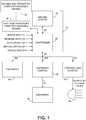
- FIG. 1A first embodiment of an exterior light control system 10 is shown in Fig. 1 .
- Exterior light control system 10is provided for controlling exterior lights 80 and, optionally, other equipment (50, 62) of a controlled vehicle.
- System 10includes an imaging system 20 and a controller 30.
- Imaging system 20includes an image sensor (201, Fig. 2 ) that is configured to image a scene external and forward of the controlled vehicle and to generate image data corresponding to the acquired images.
- Controller 30receives and analyzes the image data and generates an exterior light control signal that is used to control exterior lights 80 and may generate control signals to control any additional equipment (50, 62). These control signals are generated in response to analysis of the image data.
- Controller 30may be configured to directly connect to the equipment (50) being controlled such that the generated control signals directly control the equipment.
- controller 30may be configured to connect to an equipment control (60 and 70), which, in turn, is connected to the equipment being controlled (62 and 80) such that the control signals generated by controller 30 only indirectly control the equipment.
- controller 30may analyze the image data from imaging system 20 so as to generate control signals that are more of a recommendation for an exterior light control 70 to use when controlling exterior lights 80.
- the control signalsmay further include not just a recommendation, but also a code representing a reason for the recommendation so that equipment controls 60 and 70 may determine whether or not to override a recommendation.
- the control signalmay include an indication of the detection of a semi-truck. Such a semi-truck detection indication is particularly useful when an equipment control (60 and 70) that is separate from controller 30 performs the direct control of the equipment.
- controller 30provides additional information to exterior light control 70 and/or equipment control 60 that was not previously made available to such equipment controls. This allows the vehicle manufacturer more flexibility in how they choose to respond to the semi-truck detection indication. Examples of which are to turn the high beam lighting off; extend the delay following a determination that the semi-truck is no longer detected so as to delay turning the high beam lighting back on; only reduce the brightness of the exterior lights in the direction of the semi-truck so as to create a "tunnel" through which the semi-truck is traveling; extend the delay for which time the "tunnel” is created; and/or to simply respond in the same manner as if an oncoming vehicle were otherwise detected. If the system is going to respond in the same manner as to any detected oncoming vehicle, the semi-truck detection indication may instead be a vehicle detection indication.
- the present imaging systemimproves upon the above-mentioned exterior light control systems by providing a system that allows auto manufacturers to respond in a manner of their choosing to the semi-truck detection indication. This also allows one common system to be used for all manufacturers regardless of whether they wish to change or maintain a particular illumination pattern in response to such an indication. Further, different features of equipment control may be enabled or disabled based upon the detection of an oncoming semi-truck. In addition, different equipment may respond differently to the semi-truck detection indication.
- various inputsmay be provided to controller 30 that may be taken into account in forming a recommendation or direct control signal.
- such inputsmay instead be provided to equipment control (60 and 70).
- equipment control60 and 70
- input from manual switchesmay be provided to equipment control (60 and 70), which may allow equipment control (60 and 70) to override a recommendation from controller 30.
- controller 30 and equipment controls60 and 70
- One reason for separating control functionsis to allow imaging system 20 to be located in the best location in the vehicle for obtaining images, which may be a distance from the equipment to be controlled and to allow communication over the vehicle bus 25.
- the equipment that system 10 controlsmay include one or more exterior lights 80 and the control signal generated by controller 30 may be an exterior light control signal.
- exterior lights 80may be controlled directly by controller 30 or by an exterior light control 70, which receives a control signal from controller 30.
- the "exterior lights”broadly include any exterior lighting on the vehicle. Such exterior lights may include headlamps (both low and high beam if separate from one another), tail lights, foul weather lights such as fog lights, brake lights, center-mounted stop lights (CHMSLs), turn signals, back-up lights, etc.
- the exterior lightsmay be operated in several different modes including conventional low-beam and high-beam states. They may also be operated as daytime running lights, and additionally as super-bright high beams in those countries where they are permitted.
- the exterior light brightnessmay also be continuously varied between the low, high, and super-high states. Separate lights may be provided for obtaining each of these exterior lighting states or the actual brightness of the exterior lights may be varied to provide these different exterior lighting states. In either case, the "perceived brightness” or illumination pattern of the exterior lights is varied. As used herein, the term “perceived brightness” means the brightness of the exterior lights as perceived by an observer outside the vehicle. Most typically, such observers will be drivers or passengers in a preceding vehicle or in a vehicle traveling along the same street in the opposite direction.
- the exterior lightsare controlled such that if an observer is located in a vehicle within a "glare area" relative to the vehicle (i.e., the area in which the observer would perceive the brightness of the exterior lights as causing excessive glare), the beam illumination pattern is varied such that the observer is no longer in the glare area.
- the perceived brightness and/or glare area of the exterior lightsmay be varied by changing the illumination output of one or more exterior lights, by steering one or more lights to change the aim of one or more of the exterior lights, selectively blocking or otherwise activating or deactivating some or all of the exterior lights, altering the illumination pattern forward of the vehicle, or a combination of the above.
- Imaging system 20may be any conventional system. Examples of suitable imaging systems are disclosed in published United States Patent Application Publication Nos. US 20080192132 A1 and US 20120072080 A1 , and in United States Provisional Application Nos. 61/500,418 entitled “MEDIAN FILTER” filed on June 23, 2011, by Jon H. Bechtel et al. ; 61/544,315 entitled “MEDIAN FILTER” and filed on October 7, 2011, by Jon H. Bechtel et al. ; and 61/556,864 entitled "HIGH DYNAMIC RANGE CAMERA LOW LIGHT LEVEL FILTERING" filed on November 8, 2011, by Jon H. Bechtel et al. , the entire disclosures of which are incorporated herein by reference.
- the imaging systemincludes an image sensor (or camera) to capture images that may then be displayed and/or analyzed in order to control vehicle equipment in addition to exterior lights.
- imagershave been used for lane departure warning systems, forward collision warning systems, adaptive cruise control systems, pedestrian detection systems, night vision systems, terrain detection systems, parking assist systems, traffic sign recognition systems, and reverse camera display systems. Examples of systems using imagers for such purposes are disclosed in United States Patent Nos.
- imaging system 20may be controlled by controller 30.
- Communication of imaging system parameters as well as image dataoccurs over communication bus 40, which may be a bi-directional serial bus, parallel bus, a combination of both, or other suitable means.
- Controller 30serves to perform equipment control functions by analyzing images from imaging system 20, determining an equipment (or exterior light) state based upon information detected within those images, and communicating the determined equipment (or exterior light) state to the equipment 50, equipment control 60, or exterior light control 70 through bus 42, which may be the vehicle bus 25, a CAN bus, a LIN bus or any other suitable communication link.
- Controller 30may control the imaging system to be activated in several different modes with different exposure times and different readout windows. Controller 30 may be used to both perform the equipment or exterior light control function and control the parameters of imaging system 20.
- Controller 30can also take advantage of the availability of signals (such as vehicle speed and yaw) communicated via discrete connections or over the vehicle bus 25 in making decisions regarding the operation of the exterior lights 80.
- speed input 21provides vehicle speed information to the controller 30 from which speed can be a factor in determining the control state for the exterior lights 80 or other equipment.
- the reverse signal 22informs controller 30 that the vehicle is in reverse, responsive to which the controller 30 may clear an electrochromic mirror element regardless of signals output from light sensors.
- Auto ON/OFF switch input 23is connected to a switch having two states to dictate to controller 30 whether the vehicle exterior lights 80 should be automatically or manually controlled.
- the auto ON/OFF switch (not shown) connected to the ON/OFF switch input 23may be incorporated with the headlamp switches that are traditionally mounted on the vehicle dashboard or incorporated into steering wheel column levels.
- Manual dimmer switch input 24is connected to a manually actuated switch (not shown) to provide a manual override signal for an exterior light control state.
- Some or all of the inputs 21, 22, 23, 24 and outputs 42a, 42b, and 42c, as well as any other possible inputs or outputs, such as a steering wheel input,can optionally be provided through vehicle bus 25 shown in Fig. 1 .
- these inputs 21-24may be provided to equipment control 60 or exterior light control 70.
- Controller 30can control, at least in part, other equipment 50 within the vehicle which is connected to controller 30 via vehicle bus 42.
- equipment 50that may be controlled by controller 30: exterior lights 80, a rain sensor, a compass, information displays, windshield wipers, a heater, a defroster, a defogger, an air conditioning system, a telephone system, a navigation system, a security system, a tire pressure monitoring system, a garage door opening transmitter, a remote keyless entry system, a telematics system, a voice recognition system such as a digital signal processor-based voice actuation system, a vehicle speed control, interior lights, rearview mirrors, an audio system, an engine control system, and various other switches and other display devices that may be located throughout the vehicle.
- controller 30may be, at least in part, located within a rearview assembly of a vehicle or located elsewhere within the vehicle.
- the controller 30may also use a second controller (or controllers), equipment control 60, which may be located in a rearview assembly or elsewhere in the vehicle in order to control certain kinds of equipment 62.
- Equipment control 60can be connected to receive via vehicle bus 42 control signals generated by controller 30.
- Equipment control 60subsequently communicates and controls equipment 62 via bus 61.
- equipment control 60may be a windshield wiper control unit which controls windshield wiper equipment, turning this equipment ON or OFF.
- Equipment controlmay also be an electrochromic mirror control unit where controller 30 is programmed to communicate with the electrochromic control unit in order for the electrochromic control unit to change the reflectivity of the electrochromic mirror(s) in response to information obtained from an ambient light sensor, a glare sensor, as well as any other components coupled to the processor.
- equipment control unit 60 in communication with controller 30may control the following equipment: exterior lights, a rain sensor, a compass, information displays, windshield wipers, a heater, a defroster, a defogger, air conditioning, a telephone system, a navigation system, a security system, a tire pressure monitoring system, a garage door opening transmitter, a remote keyless entry, a telemetry system, a voice recognition system such as a digital signal processor-based voice actuation system, a vehicle speed, interior lights, rearview mirrors, an audio system, a climate control, an engine control, and various other switches and other display devices that may be located throughout the vehicle.
- Portions of system 10can be advantageously integrated into a rearview assembly 200 as illustrated in Fig. 2 , wherein imaging system 20 is integrated into a mount 203 of rearview assembly 200. This location provides an unobstructed forward view through a region of the windshield 202 of the vehicle that is typically cleaned by the vehicle's windshield wipers (not shown). Additionally, mounting the image sensor 201 of imaging system 20 in the rearview assembly permits sharing of circuitry such as the power supply, microcontroller and light sensors.
- image sensor 201is mounted within rearview mount 203, which is mounted to vehicle windshield 202.
- the rearview mount 203provides an opaque enclosure for the image sensor with the exception of an aperture through which light is received from a forward external scene.
- Controller 30 of Fig. 1may be provided on a main circuit board 215 and mounted in rearview housing 204 as shown in Fig. 2 . As discussed above, controller 30 may be connected to imaging system 20 by a bus 40 or other means.
- the main circuit board 215may be mounted within rearview housing 204 by conventional means. Power and a communication link 42 with the vehicle electrical system, including the exterior lights 80 ( Fig. 1 ), are provided via a vehicle wiring harness 217 ( Fig. 2 ).
- Rearview assembly 200may include a mirror element or a display that displays a rearward view.
- the mirror elementmay be a prismatic element or an electro-optic element, such as an electrochromic element.
- This methodis described below as being implemented by controller 30 using image data received from imaging system 20.
- This methodmay be a subroutine executed by any processor, and thus this method may be embodied in a non-transitory computer readable medium having stored thereon software instructions that, when executed by a processor, cause the processor to control the equipment of the controlled vehicle, by executing the steps of the method described below.
- aspects of the inventive methodmay be achieved by software stored on a non-transitory computer readable medium or software modifications or updates to existing software residing in a non-transitory computer readable medium.
- Such software or software updatesmay be downloaded into a first non-transitory computer readable media 32 of controller 30 (or locally associated with controller 30 or some other processor) typically prior to being installed in a vehicle, from a second non-transitory computer readable media 90 located remote from first non-transitory computer readable media 32.
- Second non-transitory computer readable media 90may be in communication with first non-transitory computer readable media 32 by any suitable means, which may at least partially include the Internet or a local or wide area wired or wireless network.
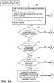
- Figs. 3A and 3Bshow a general flow chart illustrating various steps to be executed by controller 30.
- the methodmay begin with step 300 in which controller 30 determines whether certain prerequisites have been met for determining if there is an oncoming vehicle of concern (i.e., a semi-truck) when in a motorway mode relative to each light in the detected light list.
- controller 30determines (a) whether it is in a motorway mode, (b) if world position estimates are available for the lights in the detected light list, (c) if grouping information is available for the lights, and (d) if road model information is available for the scene. If these prerequisites have not been met, controller 30 will advance to step 302 ( Fig. 3B ) in which it determines that the light in the light list is not representative of an oncoming vehicle. If these prerequisites have been met, controller 30 will advance to step 304.
- step 304controller 30 determines whether the light in the light list is part of a group of lights. Details of an example how this is determined is described below with respect to Figs. 4A and 4B . If the light is not part of a group of lights, controller 30 proceeds to step 302 in which it determines that the light in the light list is not representative of an oncoming vehicle. If the light is part of a group of lights, controller 30 then determines whether the group of lights meets certain color and brightness thresholds in step 306.
- controller 30determines whether the group of lights meets certain color and brightness thresholds. Otherwise, controller 30 advances to step 308 in which it determines whether the group of lights meets certain distance criteria. Such distance criteria may, for example, be that the group of lights is between about 5 meters and about 200 meters. If the group of lights does not meet the distance criteria, controller 30 proceeds to step 302. If the group of lights does meet the distance criteria, controller 30 computes a percent difference calculation between the lights and the road model for oncoming traffic in step 310. This calculation determines the likelihood that the group of lights is within the area where oncoming traffic is expected.
- distance criteriamay, for example, be that the group of lights is between about 5 meters and about 200 meters. If the group of lights does not meet the distance criteria, controller 30 proceeds to step 302. If the group of lights does meet the distance criteria, controller 30 computes a percent difference calculation between the lights and the road model for oncoming traffic in step 310. This calculation determines the likelihood that the group of lights is within the area where oncoming traffic is expected.
- Controller 30next determines in step 312 ( Fig. 3B ) whether the percent difference is below a defined threshold to thereby indicate that the group of lights is likely within the area where oncoming traffic is expected.
- the percent difference thresholdmay be about 60. If the percent difference is above the defined threshold, controller 30 advances to step 302 where controller 30 makes the determination that the light detected in the light list is not an oncoming vehicle. If the percent difference is below the defined threshold, controller 30 proceeds to step 314 where controller 30 makes the determination that the light detected in the light list is an oncoming vehicle in the form of a semi-truck.
- controller 30After looping through steps 300-314 for each light in the detected light list (or perhaps only until the first oncoming vehicle is detected in step 314), controller 30 proceeds to step 316 where it determines if any lights have been detected as oncoming. If not, controller 30 determines that an oncoming vehicle has not been detected in the scene in step 318. If any lights have been detected as oncoming, controller 30 determines in step 320 that an oncoming vehicle in the form of a semi-truck has been detected in the scene and controller 30 responds by generating a control signal indicating the detection of a semi-truck. Exterior light control 70 may respond to this semi-truck detection indication by reducing the brightness of the exterior lights 80 at least as projected in the direction of the detected semi-truck.
- an oncoming semi-truckmay be detected if, amongst other variables, the controller 30 has identified a group of lights.
- Figs. 4A and 4Billustrate a routine by which controller 30 may identify groups of lights.
- controller 30analyzes each light j in the detected light list relative to each remaining light k in the detected light list (step 400). Controller 30 determines in step 402 whether the World_X and World_Z positions of light j and light k are within a defined range.
- the "World”is defined relative to the controlled vehicle 500 where positions in this relative World may be designated using the coordinates World_X, which is a direction lateral to the vehicle 500, and World_Z, which is a direction longitudinal to the vehicle 500 (or in the direction of travel).
- World_Xwhich is a direction lateral to the vehicle 500
- World_Zwhich is a direction longitudinal to the vehicle 500 (or in the direction of travel).
- controller 30determines that the light k is not within a defined range of light j (of, for example, 2.5 meters laterally), controller 30 returns to step 400 to select the next remaining light k within the detected light list and again executes step 402.
- controller 30determines whether atan(Light j [World_X]+2.5m/Light j [World_Z]) and atan(Light j [World_X]-2.5m/Light j [World_Z]). Controller 30 thus continues to loop through steps 400 and 402 until either a light k is found that is within the defined range of light j , or there are no lights k left in the list. In the latter case, controller 30 then selects a new light j and continues the process of steps 400 and 402 for the new light j and the remaining lights k in the light list.
- controller 30proceeds to execute computational steps 404 through 410.
- step 404controller 30 computes a percent difference between the positions of light j and light k in World_X.
- step 406controller 30 computes a percent difference between the positions of light j and light k in World_Z.
- step 408controller 30 computes a percent difference between the positions of light j and light k for the change in image position in the previous frame and in the current frame captured by the image sensor.
- the percent differences computed in steps 404-408are combined with empirically found feature weights.
- controller 30determines whether the combined percent difference is below an empirically defined threshold in step 412. This combined percent difference threshold may, for example, be about 20. If so, controller 30 groups light j and light k in step 414 ( Fig. 4B ). If not, controller 30 does not group these particular lights and returns to step 400 to select the next light k .
- controller 30determines whether light j or light k already belongs in a group of lights. If so, controller combines all groups of lights to which lights j and k belong into one group in step 418 before returning to step 400 to process the next light k relative to the current light j . If light j or light k does not already belong in a group of lights, controller returns to step 400.
Landscapes
- Engineering & Computer Science (AREA)
- Multimedia (AREA)
- Physics & Mathematics (AREA)
- General Physics & Mathematics (AREA)
- Theoretical Computer Science (AREA)
- Mechanical Engineering (AREA)
- Signal Processing (AREA)
- Lighting Device Outwards From Vehicle And Optical Signal (AREA)
Description
- The present invention generally relates to a system and method for controlling exterior lights of a controlled vehicle, and more specifically relates to improvements in systems that control exterior lights of a controlled vehicle in response to the detection of other vehicles.
- Document'A Monocular Vision Based Advancing Lighting Automation System for Driving Assistance' by J. Rebutet al. relates to a night time vehicle detection system performing automatic headlamp control in the frame work of driving assistance. Therein, image processing enables detecting vehicles and estimating their position in order to increase driver visibility by adjusting headlamps. Detecting light spots, tracking light spots, vehicle building, and position estimation are disclosed as steps for controlling the exterior lights of a vehicle.
US 2011/0010094 A1 discloses a driver-assistance system for a vehicle that includes a camera capturing a road scene in front of the vehicle. The system determines from the captured scene whether another vehicle has a blinking turn indicator. The system may then generate a warning signal sent to the driver or to an automatic driver-assistance control.- According to one aspect of the present invention, an exterior light control system is provided for controlling headlamps of a controlled vehicle. The exterior light control system comprises: an imaging system configured to image a scene external and forward of the controlled vehicle and to generate image data corresponding to the acquired images; and a controller configured to receive and analyze the image data and for generating an exterior light control signal that is used to control the headlamps in response to analysis of the image data, wherein the controller is further configured to analyze the image data to detect an oncoming semi-truck, wherein wherein the controller detects the oncoming semi-truck by detecting groups of lights of the oncoming semi-truck other than headlamps, and wherein, when the oncoming semi-truck is detected, the controller generates an exterior light control signal that indicates the detection of the oncoming semi-truck.
- According to another aspect of the present invention, a method is provided for controlling headlamps of a controlled vehicle comprising the steps of: imaging a scene external and forward of the controlled vehicle and generating image data corresponding to the acquired images; receiving and analyzing the image data in a processor to detect at least one characteristic of the image data including those of oncoming vehicles and to detect an oncoming semi-truck, wherein the step of receiving and analyzing the image data to detect an oncoming semi-truck includes detecting groups of lights of the oncoming semi-truck other than headlamps; generating a control signal that is used to control the exterior lights in response to analysis of the image data; and generating a control signal which indicates that the oncoming semi-truck is detected.
- According to another aspect of the present invention, a non-transitory computer readable medium is provided having stored thereon software instructions that, when executed by a processor, cause the processor to generate control signals for controlling headlamps of a controlled vehicle, by executing the steps comprising: imaging a scene external and forward of the controlled vehicle and generating image data corresponding to the acquired images; receiving and analyzing the image data in the processor to detect at least one characteristic of the image data to detect an oncoming semi-truck, wherein the step of receiving and analyzing the image data to detect an oncoming semi-truck includes detecting groups of lights of the oncoming semi-truck other than headlamps; and generating a control signal from the processor that is used to control the headlamps in response to analysis of the image data wherein, when the oncoming semi-truck is detected, the control signal indicates the detection of the oncoming semi-truck.
- These and other features, advantages, and objects of the present invention will be further understood and appreciated by those skilled in the art by reference to the following specification, claims, and appended drawings.
- The present invention will be more fully understood from the detailed description and the accompanying drawings, wherein:
Fig. 1 is a block diagram of a system constructed according to one embodiment;Fig. 2 is a partial cross section of a rearview assembly incorporating a system in accordance with another embodiment;Figs. 3A and3B are a flow chart illustrating a routine for detecting oncoming vehicles;Figs. 4A and4B are a flow chart illustrating a routine for detecting groupings of lights of an oncoming vehicle; andFig. 5 is a top plan view of a vehicle illustrating a world coordinate system.- Reference will now be made in detail to the present preferred embodiments, examples of which are illustrated in the accompanying drawings. Wherever possible, the same reference numerals will be used throughout the drawings to refer to the same or like parts. In the drawings, the depicted structural elements are not to scale and certain components are enlarged relative to the other components for purposes of emphasis and understanding.
- The embodiments described herein relate to an exterior light control system for controlling exterior lights of a controlled vehicle in response to image data acquired from an image sensor, which captures images forward of the vehicle. Prior systems are known for controlling exterior vehicle lights in response to images captured forward of the vehicle. In these prior systems, a controller would analyze the captured images and determine if any preceding or oncoming vehicles were present in a glare area in front of the vehicle employing the system. This "glare area" was the area in which the exterior lights would cause excessive glare to a driver if the exterior lights were in a high-beam state (or some state other than a low-beam state). If a vehicle was present in the glare area, the controller would respond by changing the state of the exterior lights so as to not cause glare for the other driver(s). Examples of such systems are described in
United States Patent Nos. 5,837,994 ,5,990,469 ,6,008,486 ,6,049,171 ,6,130,421 ,6,130,448 ,6,166,698 ,6,379,013 ,6,403,942 ,6,587,573 ,6,611,610 ,6,631,316 ,6,774,988 ,6,861,809 ,7,321,112 ,7,417,221 ,7,565,006 ,7,567,291 ,7,653,215 ,7,683,326 ,7,881,839 ,8,045,760 , and8,120,652 , as well as inUnited States Patent Application No. 13/432,250 entitled "VEHICULAR IMAGING SYSTEM AND METHOD FOR DETERMINING ROADWAY WIDTH" and filed on March 28, 2012, by Jeremy A. Schut et al. United States Patent Application No. 13/432,250 entitled "VEHICULAR IMAGING SYSTEM AND METHOD FOR DETERMINING ROADWAY WIDTH" filed on March 28, 2012, by Jeremy A. Schut et al. - One of the modes in which the exterior lighting control systems may operate is a motorway mode. The motorway mode is selected when the system determines that the controlled vehicle is traveling on a motorway (i.e., an expressway or divided highway). In the motorway mode, the system may not be responsive to oncoming vehicles because the presence of a guard rail or other barrier in the median blocks the headlamps of oncoming vehicles making them hard to detect. However, such barriers also block light from the controlled vehicle that would otherwise cause glare to drivers of oncoming vehicles. Examples of exterior light control systems that detect motorways and operate in a motorway mode are disclosed in
United States Patent Nos. 6,861,809 and8,045,760 , the entire disclosures of which are incorporated herein by reference. - A problem has been found to exist in that semi-truck drivers can experience glare from bright exterior lights of oncoming vehicles even when driving on a motorway with a barrier in the median due to the height of the cab of the semi-truck. Thus, the prior systems which did not detect oncoming vehicles if their headlamps were blocked by such a barrier also did not reduce the brightness of the exterior lights, thereby tending to cause excessive glare to the drivers of oncoming semi-trucks whose headlamps are also blocked by the barrier.
- Accordingly, the exterior light control system of the present invention is capable of detecting oncoming semi-trucks despite being unable to detect their headlamps due to a barrier, and responds to the presence of an oncoming semi-truck by reducing the brightness of the exterior lights as perceived by the semi-truck driver. More specifically, the system may reduce or suggest the reduction of the brightness of the exterior lights in response to detection of a semi-truck while in a motorway mode even when headlamps of the semi-truck are not detected.
- As explained in further detail below, the system looks for lights on the semi-truck cabs and/or trailers by detecting groupings of lights that are in the forward scene and are positioned in such a way within the image frame that they are within a defined range of one another relative to the world surrounding the controlled vehicle and its image sensor. The system may further determine whether the positions of the lights within the group change in position from one image frame to the next in a relative manner suggesting that the lights of the group are moving collectively together. Once such a group of lights is detected, the system may determine if the color and/or brightness of the lights meets certain thresholds that further suggest the presence of a semi-truck (i.e., consistent colors of the lights in the group). The distance to the light sources may then be determined to serve as an indicator as to whether the semi-truck is close enough to justify reducing the perceived brightness of the exterior lights in at least the direction of the detected semi-truck. Further, the relative position of the detected semi-truck may be compared to a road model for oncoming traffic to determine whether the detected semi-truck is, in fact, travelling along the same path as other oncoming vehicles.
- Such road models may be determined by analyzing the relative world positions of prior oncoming traffic as detected by the system. Road models may also be determined using the controlled vehicle's navigational system. The road model may also allow the system to determine the relative height of the lights so as to determine if they are likely on a semi-truck cab or trailer. A system for determining a road model is disclosed in
United States Patent Application No. 13/432,250 entitled "VEHICULAR IMAGING SYSTEM AND METHOD FOR DETERMINING ROADWAY WIDTH" and filed on March 28, 2012 - A first embodiment of an exterior
light control system 10 is shown inFig. 1 . Exteriorlight control system 10 is provided for controllingexterior lights 80 and, optionally, other equipment (50, 62) of a controlled vehicle.System 10 includes animaging system 20 and acontroller 30.Imaging system 20 includes an image sensor (201,Fig. 2 ) that is configured to image a scene external and forward of the controlled vehicle and to generate image data corresponding to the acquired images.Controller 30 receives and analyzes the image data and generates an exterior light control signal that is used to controlexterior lights 80 and may generate control signals to control any additional equipment (50, 62). These control signals are generated in response to analysis of the image data. Controller 30 may be configured to directly connect to the equipment (50) being controlled such that the generated control signals directly control the equipment. Alternatively,controller 30 may be configured to connect to an equipment control (60 and 70), which, in turn, is connected to the equipment being controlled (62 and 80) such that the control signals generated bycontroller 30 only indirectly control the equipment. For example, in the case of the equipment beingexterior lights 80,controller 30 may analyze the image data fromimaging system 20 so as to generate control signals that are more of a recommendation for anexterior light control 70 to use when controlling exterior lights 80. The control signals may further include not just a recommendation, but also a code representing a reason for the recommendation so that equipment controls 60 and 70 may determine whether or not to override a recommendation. Further, as described in detail below, the control signal may include an indication of the detection of a semi-truck. Such a semi-truck detection indication is particularly useful when an equipment control (60 and 70) that is separate fromcontroller 30 performs the direct control of the equipment.- By providing a semi-truck detection indication,
controller 30 provides additional information toexterior light control 70 and/orequipment control 60 that was not previously made available to such equipment controls. This allows the vehicle manufacturer more flexibility in how they choose to respond to the semi-truck detection indication. Examples of which are to turn the high beam lighting off; extend the delay following a determination that the semi-truck is no longer detected so as to delay turning the high beam lighting back on; only reduce the brightness of the exterior lights in the direction of the semi-truck so as to create a "tunnel" through which the semi-truck is traveling; extend the delay for which time the "tunnel" is created; and/or to simply respond in the same manner as if an oncoming vehicle were otherwise detected. If the system is going to respond in the same manner as to any detected oncoming vehicle, the semi-truck detection indication may instead be a vehicle detection indication. - The present imaging system improves upon the above-mentioned exterior light control systems by providing a system that allows auto manufacturers to respond in a manner of their choosing to the semi-truck detection indication. This also allows one common system to be used for all manufacturers regardless of whether they wish to change or maintain a particular illumination pattern in response to such an indication. Further, different features of equipment control may be enabled or disabled based upon the detection of an oncoming semi-truck. In addition, different equipment may respond differently to the semi-truck detection indication.
- As shown in
Fig. 1 , various inputs (such as inputs 21-24) may be provided tocontroller 30 that may be taken into account in forming a recommendation or direct control signal. In some cases, such inputs may instead be provided to equipment control (60 and 70). For example, input from manual switches may be provided to equipment control (60 and 70), which may allow equipment control (60 and 70) to override a recommendation fromcontroller 30. It will be appreciated that various levels of interaction and cooperation betweencontroller 30 and equipment controls (60 and 70) may exist. One reason for separating control functions is to allowimaging system 20 to be located in the best location in the vehicle for obtaining images, which may be a distance from the equipment to be controlled and to allow communication over the vehicle bus 25. - According to one embodiment, the equipment that
system 10 controls may include one or moreexterior lights 80 and the control signal generated bycontroller 30 may be an exterior light control signal. In this embodiment,exterior lights 80 may be controlled directly bycontroller 30 or by anexterior light control 70, which receives a control signal fromcontroller 30. As used herein, the "exterior lights" broadly include any exterior lighting on the vehicle. Such exterior lights may include headlamps (both low and high beam if separate from one another), tail lights, foul weather lights such as fog lights, brake lights, center-mounted stop lights (CHMSLs), turn signals, back-up lights, etc. The exterior lights may be operated in several different modes including conventional low-beam and high-beam states. They may also be operated as daytime running lights, and additionally as super-bright high beams in those countries where they are permitted. - The exterior light brightness may also be continuously varied between the low, high, and super-high states. Separate lights may be provided for obtaining each of these exterior lighting states or the actual brightness of the exterior lights may be varied to provide these different exterior lighting states. In either case, the "perceived brightness" or illumination pattern of the exterior lights is varied. As used herein, the term "perceived brightness" means the brightness of the exterior lights as perceived by an observer outside the vehicle. Most typically, such observers will be drivers or passengers in a preceding vehicle or in a vehicle traveling along the same street in the opposite direction. Ideally, the exterior lights are controlled such that if an observer is located in a vehicle within a "glare area" relative to the vehicle (i.e., the area in which the observer would perceive the brightness of the exterior lights as causing excessive glare), the beam illumination pattern is varied such that the observer is no longer in the glare area. The perceived brightness and/or glare area of the exterior lights may be varied by changing the illumination output of one or more exterior lights, by steering one or more lights to change the aim of one or more of the exterior lights, selectively blocking or otherwise activating or deactivating some or all of the exterior lights, altering the illumination pattern forward of the vehicle, or a combination of the above.
Imaging system 20 may be any conventional system. Examples of suitable imaging systems are disclosed in published United States Patent Application Publication Nos.US 20080192132 A1 andUS 20120072080 A1 , and inUnited States Provisional Application Nos. 61/500,418 entitled "MEDIAN FILTER" filed on June 23, 2011, by Jon H. Bechtel et al. 61/544,315 entitled "MEDIAN FILTER" and filed on October 7, 2011, by Jon H. Bechtel et al. 61/556,864 entitled "HIGH DYNAMIC RANGE CAMERA LOW LIGHT LEVEL FILTERING" filed on November 8, 2011, by Jon H. Bechtel et al. - The imaging system includes an image sensor (or camera) to capture images that may then be displayed and/or analyzed in order to control vehicle equipment in addition to exterior lights. For example, such imagers have been used for lane departure warning systems, forward collision warning systems, adaptive cruise control systems, pedestrian detection systems, night vision systems, terrain detection systems, parking assist systems, traffic sign recognition systems, and reverse camera display systems. Examples of systems using imagers for such purposes are disclosed in
United States Patent Nos. 5,837,994 ,5,990,469 ,6,008,486 ,6,049,171 ,6,130,421 ,6,130,448 ,6,166,698 ,6,379,013 ,6,403,942 ,6,587,573 ,6,611,610 ,6,631,316 ,6,774,988 ,6,861,809 ,7,321,112 ,7,417,221 ,7,565,006 ,7,567,291 ,7,653,215 ,7,683,326 ,7,881,839 ,8,045,760 , and8,120,652 , and inUnited States Provisional Application Nos. 61/512,213 entitled "RAISED LANE MARKER DETECTION SYSEM AND METHOD THEREOF" and filed on July 27, 2011, by Brock R. Rycenga et al. 61/512,158 entitled "COLLISION WARNING SYSTEM AND METHOD THEREOF" and filed on July 27, 2011, by Brock R. Rycenga et al. - In the example shown in
Fig. 1 ,imaging system 20 may be controlled bycontroller 30. Communication of imaging system parameters as well as image data occurs overcommunication bus 40, which may be a bi-directional serial bus, parallel bus, a combination of both, or other suitable means.Controller 30 serves to perform equipment control functions by analyzing images fromimaging system 20, determining an equipment (or exterior light) state based upon information detected within those images, and communicating the determined equipment (or exterior light) state to theequipment 50,equipment control 60, orexterior light control 70 throughbus 42, which may be the vehicle bus 25, a CAN bus, a LIN bus or any other suitable communication link.Controller 30 may control the imaging system to be activated in several different modes with different exposure times and different readout windows.Controller 30 may be used to both perform the equipment or exterior light control function and control the parameters ofimaging system 20. Controller 30 can also take advantage of the availability of signals (such as vehicle speed and yaw) communicated via discrete connections or over the vehicle bus 25 in making decisions regarding the operation of the exterior lights 80. In particular,speed input 21 provides vehicle speed information to thecontroller 30 from which speed can be a factor in determining the control state for theexterior lights 80 or other equipment. The reverse signal 22 informscontroller 30 that the vehicle is in reverse, responsive to which thecontroller 30 may clear an electrochromic mirror element regardless of signals output from light sensors. Auto ON/OFF switch input 23 is connected to a switch having two states to dictate tocontroller 30 whether the vehicle exterior lights 80 should be automatically or manually controlled. The auto ON/OFF switch (not shown) connected to the ON/OFF switch input 23 may be incorporated with the headlamp switches that are traditionally mounted on the vehicle dashboard or incorporated into steering wheel column levels. Manualdimmer switch input 24 is connected to a manually actuated switch (not shown) to provide a manual override signal for an exterior light control state. Some or all of theinputs outputs Fig. 1 . Alternatively, these inputs 21-24 may be provided toequipment control 60 orexterior light control 70.Controller 30 can control, at least in part,other equipment 50 within the vehicle which is connected tocontroller 30 viavehicle bus 42. Specifically, the following are some examples of one ormore equipment 50 that may be controlled by controller 30:exterior lights 80, a rain sensor, a compass, information displays, windshield wipers, a heater, a defroster, a defogger, an air conditioning system, a telephone system, a navigation system, a security system, a tire pressure monitoring system, a garage door opening transmitter, a remote keyless entry system, a telematics system, a voice recognition system such as a digital signal processor-based voice actuation system, a vehicle speed control, interior lights, rearview mirrors, an audio system, an engine control system, and various other switches and other display devices that may be located throughout the vehicle.- In addition,
controller 30 may be, at least in part, located within a rearview assembly of a vehicle or located elsewhere within the vehicle. Thecontroller 30 may also use a second controller (or controllers),equipment control 60, which may be located in a rearview assembly or elsewhere in the vehicle in order to control certain kinds ofequipment 62.Equipment control 60 can be connected to receive viavehicle bus 42 control signals generated bycontroller 30.Equipment control 60 subsequently communicates and controlsequipment 62 viabus 61. For example,equipment control 60 may be a windshield wiper control unit which controls windshield wiper equipment, turning this equipment ON or OFF. Equipment control may also be an electrochromic mirror control unit wherecontroller 30 is programmed to communicate with the electrochromic control unit in order for the electrochromic control unit to change the reflectivity of the electrochromic mirror(s) in response to information obtained from an ambient light sensor, a glare sensor, as well as any other components coupled to the processor. Specifically,equipment control unit 60 in communication withcontroller 30 may control the following equipment: exterior lights, a rain sensor, a compass, information displays, windshield wipers, a heater, a defroster, a defogger, air conditioning, a telephone system, a navigation system, a security system, a tire pressure monitoring system, a garage door opening transmitter, a remote keyless entry, a telemetry system, a voice recognition system such as a digital signal processor-based voice actuation system, a vehicle speed, interior lights, rearview mirrors, an audio system, a climate control, an engine control, and various other switches and other display devices that may be located throughout the vehicle. - Portions of
system 10 can be advantageously integrated into arearview assembly 200 as illustrated inFig. 2 , whereinimaging system 20 is integrated into amount 203 ofrearview assembly 200. This location provides an unobstructed forward view through a region of thewindshield 202 of the vehicle that is typically cleaned by the vehicle's windshield wipers (not shown). Additionally, mounting theimage sensor 201 ofimaging system 20 in the rearview assembly permits sharing of circuitry such as the power supply, microcontroller and light sensors. - Referring to
Fig. 2 ,image sensor 201 is mounted withinrearview mount 203, which is mounted tovehicle windshield 202. Therearview mount 203 provides an opaque enclosure for the image sensor with the exception of an aperture through which light is received from a forward external scene. Controller 30 ofFig. 1 may be provided on amain circuit board 215 and mounted inrearview housing 204 as shown inFig. 2 . As discussed above,controller 30 may be connected toimaging system 20 by abus 40 or other means. Themain circuit board 215 may be mounted withinrearview housing 204 by conventional means. Power and acommunication link 42 with the vehicle electrical system, including the exterior lights 80 (Fig. 1 ), are provided via a vehicle wiring harness 217 (Fig. 2 ).Rearview assembly 200 may include a mirror element or a display that displays a rearward view. The mirror element may be a prismatic element or an electro-optic element, such as an electrochromic element.- Additional details of the manner by which
system 10 may be integrated into arearview mirror assembly 200 are described inU.S. Patent No. 6,611,610 , the entire disclosure of which is incorporated herein by reference. Alternative rearview mirror assembly constructions used to implement exterior light control systems are disclosed inU.S. Patent No. 6,587,573 , the entire disclosure of which is incorporated herein by reference. - The method for controlling exterior lights of a controlled vehicle will now be described with reference to
Figs. 3A-5 . This method is described below as being implemented bycontroller 30 using image data received fromimaging system 20. This method may be a subroutine executed by any processor, and thus this method may be embodied in a non-transitory computer readable medium having stored thereon software instructions that, when executed by a processor, cause the processor to control the equipment of the controlled vehicle, by executing the steps of the method described below. In other words, aspects of the inventive method may be achieved by software stored on a non-transitory computer readable medium or software modifications or updates to existing software residing in a non-transitory computer readable medium. Such software or software updates may be downloaded into a first non-transitory computerreadable media 32 of controller 30 (or locally associated withcontroller 30 or some other processor) typically prior to being installed in a vehicle, from a second non-transitory computerreadable media 90 located remote from first non-transitory computerreadable media 32. Second non-transitory computerreadable media 90 may be in communication with first non-transitory computerreadable media 32 by any suitable means, which may at least partially include the Internet or a local or wide area wired or wireless network. Figs. 3A and3B show a general flow chart illustrating various steps to be executed bycontroller 30. As shown inFig. 3A , the method may begin withstep 300 in whichcontroller 30 determines whether certain prerequisites have been met for determining if there is an oncoming vehicle of concern (i.e., a semi-truck) when in a motorway mode relative to each light in the detected light list. In particular,controller 30 determines (a) whether it is in a motorway mode, (b) if world position estimates are available for the lights in the detected light list, (c) if grouping information is available for the lights, and (d) if road model information is available for the scene. If these prerequisites have not been met,controller 30 will advance to step 302 (Fig. 3B ) in which it determines that the light in the light list is not representative of an oncoming vehicle. If these prerequisites have been met,controller 30 will advance to step 304.- In
step 304,controller 30 determines whether the light in the light list is part of a group of lights. Details of an example how this is determined is described below with respect toFigs. 4A and4B . If the light is not part of a group of lights,controller 30 proceeds to step 302 in which it determines that the light in the light list is not representative of an oncoming vehicle. If the light is part of a group of lights,controller 30 then determines whether the group of lights meets certain color and brightness thresholds instep 306. - If, in
step 306,controller 30 determines that the group of lights does not meet certain color and brightness thresholds,controller 30 advances to step 302. Otherwise,controller 30 advances to step 308 in which it determines whether the group of lights meets certain distance criteria. Such distance criteria may, for example, be that the group of lights is between about 5 meters and about 200 meters. If the group of lights does not meet the distance criteria,controller 30 proceeds to step 302. If the group of lights does meet the distance criteria,controller 30 computes a percent difference calculation between the lights and the road model for oncoming traffic instep 310. This calculation determines the likelihood that the group of lights is within the area where oncoming traffic is expected. Controller 30 next determines in step 312 (Fig. 3B ) whether the percent difference is below a defined threshold to thereby indicate that the group of lights is likely within the area where oncoming traffic is expected. As an example, the percent difference threshold may be about 60. If the percent difference is above the defined threshold,controller 30 advances to step 302 wherecontroller 30 makes the determination that the light detected in the light list is not an oncoming vehicle. If the percent difference is below the defined threshold,controller 30 proceeds to step 314 wherecontroller 30 makes the determination that the light detected in the light list is an oncoming vehicle in the form of a semi-truck.- After looping through steps 300-314 for each light in the detected light list (or perhaps only until the first oncoming vehicle is detected in step 314),
controller 30 proceeds to step 316 where it determines if any lights have been detected as oncoming. If not,controller 30 determines that an oncoming vehicle has not been detected in the scene instep 318. If any lights have been detected as oncoming,controller 30 determines instep 320 that an oncoming vehicle in the form of a semi-truck has been detected in the scene andcontroller 30 responds by generating a control signal indicating the detection of a semi-truck.Exterior light control 70 may respond to this semi-truck detection indication by reducing the brightness of theexterior lights 80 at least as projected in the direction of the detected semi-truck. - As mentioned with respect to step 304 in
Fig. 3A , an oncoming semi-truck may be detected if, amongst other variables, thecontroller 30 has identified a group of lights. Figs. 4A and4B illustrate a routine by whichcontroller 30 may identify groups of lights. In this routine,controller 30 analyzes each lightj in the detected light list relative to each remaining light k in the detected light list (step 400).Controller 30 determines instep 402 whether the World_X and World_Z positions of lightj and lightk are within a defined range. As shown inFig. 5 , the "World" is defined relative to the controlledvehicle 500 where positions in this relative World may be designated using the coordinates World_X, which is a direction lateral to thevehicle 500, and World_Z, which is a direction longitudinal to the vehicle 500 (or in the direction of travel). By determining if the positions of two light sources are within a defined range, the controller is determining whether they could possibly be associated with the same semi-truck.- If, in
step 402,controller 30 determines that the lightk is not within a defined range of lightj (of, for example, 2.5 meters laterally),controller 30 returns to step 400 to select the next remaining lightk within the detected light list and again executesstep 402. To compute whether the lightk is within a defined range of lightj,controller 30 determines whether atan(Lightj[World_X]+2.5m/Lightj[World_Z]) and atan(Lightj[World_X]-2.5m/Lightj[World_Z]).Controller 30 thus continues to loop throughsteps controller 30 then selects a new lightj and continues the process ofsteps - If a lightk is found that is within the defined range of lightj,
controller 30 proceeds to executecomputational steps 404 through 410. Instep 404,controller 30 computes a percent difference between the positions of lightj and lightk in World_X. Instep 406,controller 30 computes a percent difference between the positions of lightj and lightk in World_Z. Instep 408,controller 30 computes a percent difference between the positions of lightj and lightk for the change in image position in the previous frame and in the current frame captured by the image sensor. Instep 410, the percent differences computed in steps 404-408 are combined with empirically found feature weights. - After
step 410,controller 30 determines whether the combined percent difference is below an empirically defined threshold instep 412. This combined percent difference threshold may, for example, be about 20. If so,controller 30 groups lightj and lightk in step 414 (Fig. 4B ). If not,controller 30 does not group these particular lights and returns to step 400 to select the next lightk. - Following
step 414,controller 30 then determines whether lightj or lightk already belongs in a group of lights. If so, controller combines all groups of lights to which lightsj andk belong into one group instep 418 before returning to step 400 to process the next lightk relative to the current lightj. If lightj or lightk does not already belong in a group of lights, controller returns to step 400. - The routine in
Figs. 4A and4B is thus repeated for each lightj in the detected light list. - The above description is considered that of the preferred embodiments only. Modifications of the invention will occur to those skilled in the art and to those who make or use the invention. Therefore, it is understood that the embodiments shown in the drawings and described above are merely for illustrative purposes and not intended to limit the scope of the invention, which is defined by the claims.
Claims (12)
- An exterior light control system (10) for controlling headlamps of a controlled vehicle, comprising:an imaging system (20) configured to image a scene external and forward of the controlled vehicle and to generate image data corresponding to the acquired images; anda controller (30) configured to receive and analyze the image data and for generating an exterior light control signal that is used to control the headlamps in response to analysis of the image data,wherein said controller (30) is further configured to analyze the image data to detect an oncoming semi-truck,wherein said controller (30) detects the oncoming semi-truck by detecting groups of lights of the oncoming semi-truck other than headlamps, andwherein, when the oncoming semi-truck is detected, said controller generates an exterior light control signal that indicates the detection of the oncoming semi-truck.
- The exterior light control system (10) of claim 1 wherein:said controller (30) generates an exterior light control signal in response to analysis of the image data and in response to a selected mode of operation, wherein one selected mode of operation is a motorway mode, andwhen in the motorway mode, if said controller (30) detects the oncoming semi-truck, said controller (30) generates an exterior light control signal for reducing the brightness of the headlamps.
- The exterior light control system (10) of any one of claims 1 and 2 wherein said controller (30) is further configured to analyze the image data to detect the oncoming semi-truck even when headlamps of the semi-truck are not detected.
- The exterior light control system (10) of any one of claims 1 - 3, wherein said controller (30) determines that detected lights belong in a group by determining whether the lights are within a defined range of one another.
- The exterior light control system (10) of any one of claims 1 - 4, wherein said controller (30) determines that detected lights belong in a group by determining whether positions of the lights change collectively together over time.
- The exterior light control system (10) of any one of claims 1 - 5, wherein said controller (30) determines that detected lights belong in a group by determining whether the lights have at least one of color and brightness levels within threshold levels of one another.
- The exterior light control system (10) of any one of claims 1 - 6, wherein said controller (30) determines a position of a detected group of lights relative to a road model to determine if the group of lights are those of the oncoming semi-truck.
- A method for controlling headlamps of a controlled vehicle, comprising:imaging a scene external and forward of the controlled vehicle and generating image data corresponding to the acquired images;receiving and analyzing the image data in a processor to detect at least one characteristic of the image data including those of oncoming vehicles and to detect an oncoming semi-truck, wherein the step of receiving and analyzing the image data to detect an oncoming semi-truck includes detecting groups of lights of the oncoming semi-truck other than headlamps;generating a control signal that is used to control the headlamps in response to analysis of the image data; andgenerating a control signal which indicates that the oncoming semi-truck is detected.
- A non-transitory computer readable medium having stored thereon software instructions that, when executed by a processor, cause the processor to generate control signals for controlling headlamps of a controlled vehicle, by executing the steps comprising:imaging a scene external and forward of the controlled vehicle and generating image data corresponding to the acquired images;receiving and analyzing the image data in the processor to detect at least one characteristic of the image data to detect an oncoming semi-truck, wherein the step of receiving and analyzing the image data to detect an oncoming semi-truck includes detecting groups of lights of the oncoming semi-truck other than headlamps; andgenerating a control signal from the processor that is used to control the headlamps in response to analysis of the image data wherein, when the oncoming semi-truck is detected, the control signal indicates the detection of the oncoming semi-truck.
- The non-transitory computer readable medium of claim 9 having stored thereon software instructions that, when executed by the processor, cause the processor to generate control signals for controlling headlamps of a controlled vehicle, by executing the additional steps comprising:further analyzing the image data in the processor to select a mode of operation, wherein one mode of operation is a motorway mode; andwhen in a motorway mode, generating a control signal for reducing the brightness of the headlamps if the oncoming semi-truck is detected.
- The non-transitory computer readable medium of any one of claims 9 and 10, wherein the processor is further configured to analyze the image data to detect the oncoming semi-truck even when headlamps of the semi-truck are not detected.
- The non-transitory computer readable medium of any one of claims 9 - 11, wherein the determination that detected lights belong in a group includes determining whether the lights are within a defined range of one another.
Applications Claiming Priority (2)
| Application Number | Priority Date | Filing Date | Title |
|---|---|---|---|
| US201261678658P | 2012-08-02 | 2012-08-02 | |
| PCT/US2013/053152WO2014022630A1 (en) | 2012-08-02 | 2013-08-01 | System and method for controlling exterior vehicle lights responsive to detection of a semi-truck |
Publications (3)
| Publication Number | Publication Date |
|---|---|
| EP2879912A1 EP2879912A1 (en) | 2015-06-10 |
| EP2879912A4 EP2879912A4 (en) | 2016-01-27 |
| EP2879912B1true EP2879912B1 (en) | 2021-11-10 |
Family
ID=50025109
Family Applications (1)
| Application Number | Title | Priority Date | Filing Date |
|---|---|---|---|
| EP13826453.6AActiveEP2879912B1 (en) | 2012-08-02 | 2013-08-01 | System and method for controlling exterior vehicle lights responsive to detection of a semi-truck |
Country Status (4)
| Country | Link |
|---|---|
| US (1) | US8964024B2 (en) |
| EP (1) | EP2879912B1 (en) |
| CN (1) | CN104583012B (en) |
| WO (1) | WO2014022630A1 (en) |
Families Citing this family (17)
| Publication number | Priority date | Publication date | Assignee | Title |
|---|---|---|---|---|
| DE102011081397A1 (en)* | 2011-08-23 | 2013-02-28 | Robert Bosch Gmbh | Method for estimating a road course and method for controlling a light emission of at least one headlight of a vehicle |
| WO2015026823A1 (en)* | 2013-08-19 | 2015-02-26 | Gentex Corporation | Vehicle imaging system and method for distinguishing between vehicle tail lights and flashing red stop lights |
| EP3036132B1 (en) | 2013-08-19 | 2019-02-27 | Gentex Corporation | Vehicle imaging system and method for distinguishing reflective objects from lights of another vehicle |
| EP3052341B1 (en) | 2013-10-01 | 2021-12-01 | Gentex Corporation | System and method for controlling exterior vehicle lights on motorways |
| KR101794821B1 (en) | 2013-11-15 | 2017-11-07 | 젠텍스 코포레이션 | Imaging system including dynamic compensation for color attenuation for vehicle windscreens |
| CN104924877B (en)* | 2014-03-18 | 2017-10-10 | 鸿富锦精密工业(深圳)有限公司 | Automobile and the anti-glare method of automobile |
| US10029608B2 (en)* | 2015-09-04 | 2018-07-24 | Ford Global Technologies, Llc | Automatic vehicle lighting control |
| DE102016200323A1 (en) | 2016-01-13 | 2017-07-13 | Hella Kgaa Hueck & Co. | Method for detecting a glare situation and for the corresponding control of at least one light-emitting element |
| US10906463B2 (en) | 2016-02-01 | 2021-02-02 | Magna Electronics Inc. | Vehicle adaptive lighting system |
| DE102016115076A1 (en)* | 2016-08-15 | 2018-02-15 | Valeo Schalter Und Sensoren Gmbh | A method for detecting a vehicle lighting of a vehicle in an environment of a motor vehicle, control device, lighting device and motor vehicle |
| CN107776572A (en)* | 2016-08-31 | 2018-03-09 | 奥迪股份公司 | Vehicle assistant drive method and system |
| JP7110650B2 (en)* | 2018-03-22 | 2022-08-02 | マツダ株式会社 | Vehicle headlight switch device |
| KR20200048145A (en)* | 2018-10-29 | 2020-05-08 | 현대모비스 주식회사 | Apparatus and method for controlling a head lamp |
| KR20220022898A (en)* | 2019-06-20 | 2022-02-28 | 젠텍스 코포레이션 | Systems and Methods for Automated Modular Lighting and Placement |
| US11872929B2 (en)* | 2020-01-14 | 2024-01-16 | Qualcomm Incorporated | Collaborative vehicle headlight directing |
| JP2024115462A (en)* | 2023-02-14 | 2024-08-26 | 株式会社Subaru | Vehicles with road surface drawing function |
| JP2024132428A (en)* | 2023-03-17 | 2024-10-01 | 本田技研工業株式会社 | Vehicle lighting device and lighting device |
Family Cites Families (178)
| Publication number | Priority date | Publication date | Assignee | Title |
|---|---|---|---|---|
| US2131888A (en) | 1933-11-06 | 1938-10-04 | Floyd M Harris | Automobile lighting system |
| US2632040A (en) | 1952-05-01 | 1953-03-17 | Rabinow Jacob | Automatic headlight dimmer |
| US2827594A (en) | 1954-09-02 | 1958-03-18 | Rabinow Jacob | Color discriminating headlight dimmer |
| US3179845A (en) | 1961-05-01 | 1965-04-20 | Kulwiec Chester | Headlight illumination and signaling system for motor vehicles |
| US3581276A (en) | 1968-03-22 | 1971-05-25 | Essex International Inc | Vehicle light control and warning indicator system |
| US3663819A (en) | 1969-07-23 | 1972-05-16 | Lucas Industries Ltd | Road vehicle lighting system in which same shutter obscures photocell when system is operative and when it is not energized |
| JPS5844228B2 (en) | 1976-07-08 | 1983-10-01 | トヨタ自動車株式会社 | Obstacle detection radar for vehicles |
| US4139801A (en) | 1977-01-26 | 1979-02-13 | Linares Raul F | Automatic automobile light control system |
| US4258979A (en) | 1978-12-08 | 1981-03-31 | Mahin William E | Rear view mirror assembly |
| US4236099A (en) | 1979-03-05 | 1980-11-25 | Irving Rosenblum | Automatic headlight system |
| US4376909A (en) | 1979-04-13 | 1983-03-15 | Honda Giken Kogyo Kabushiki Kaisha | Automatic light control for automotive vehicles |
| US4286308A (en) | 1979-09-04 | 1981-08-25 | Polaroid Corporation | Apparatus and method for reducing headlight glare |
| FR2492748A2 (en) | 1979-11-07 | 1982-04-30 | Massoni Francois | DEVICE FOR AUTOMATICALLY CONTROLLING IGNITION AND EXTINGUISHING LIGHTS IN A VEHICLE |
| DE2946561A1 (en) | 1979-11-17 | 1981-05-27 | Bosch Gmbh Robert | Automatic vehicle headlamp light distribution testing and video system - has microcomputer-controlled signal analyser and calibration lamp arrangement |
| US6772057B2 (en) | 1995-06-07 | 2004-08-03 | Automotive Technologies International, Inc. | Vehicular monitoring systems using image processing |
| US6507779B2 (en) | 1995-06-07 | 2003-01-14 | Automotive Technologies International, Inc. | Vehicle rear seat monitor |
| US5845000A (en) | 1992-05-05 | 1998-12-01 | Automotive Technologies International, Inc. | Optical identification and monitoring system using pattern recognition for use with vehicles |
| US6442465B2 (en) | 1992-05-05 | 2002-08-27 | Automotive Technologies International, Inc. | Vehicular component control systems and methods |
| US4479173A (en) | 1983-04-21 | 1984-10-23 | Rumpakis George E | Lighted instrument assembly |
| JPS60117218A (en)* | 1983-11-29 | 1985-06-24 | Nippon Denso Co Ltd | Liquid crystal antidazzling type reflecting mirror |
| US4692798A (en) | 1984-01-09 | 1987-09-08 | Nissan Motor Company, Limited | Apparatus and process for improving visibility of object within visual field |
| US4599544A (en) | 1984-05-24 | 1986-07-08 | General Motors Corporation | Vehicle headlamp beam control |
| JPS60256076A (en) | 1984-06-01 | 1985-12-17 | Nissan Motor Co Ltd | Apparatus for detecting preceding car |
| US4645975A (en) | 1984-09-04 | 1987-02-24 | Ford Motor Company | Composite light pickup device |
| NO850900L (en) | 1985-03-06 | 1986-09-08 | Hans Christian Flaaten | DEVICE FOR AUTOMATIC, SELECTIVE LIGHT CONTROL FOR VEHICLES. |
| US4891559A (en) | 1985-06-13 | 1990-01-02 | Nippondenso Soken, Inc. | Apparatus for controlling a headlight of a vehicle |
| US4665321A (en) | 1985-08-14 | 1987-05-12 | Kwangling Chang | Automatic control system for automobile lights |
| DE3601388A1 (en) | 1986-01-18 | 1987-07-23 | Bosch Gmbh Robert | HEADLIGHT SYSTEM FOR VEHICLES, ESPECIALLY FOR MOTOR VEHICLES |
| JPS62131837U (en) | 1986-02-12 | 1987-08-20 | ||
| US4727290A (en) | 1987-05-29 | 1988-02-23 | General Motors Corporation | Automatic vehicle headlamp dimming control |
| JPH01158579A (en) | 1987-09-09 | 1989-06-21 | Aisin Seiki Co Ltd | Image recognizing device |
| US4862037A (en) | 1987-12-24 | 1989-08-29 | Ford Motor Company | Automatic headlamp dimming system |
| JPH07110594B2 (en) | 1988-03-14 | 1995-11-29 | 日産自動車株式会社 | Optical axis changing device for irradiation lamp |
| US4930742A (en) | 1988-03-25 | 1990-06-05 | Donnelly Corporation | Rearview mirror and accessory mount for vehicles |
| JPH01278848A (en) | 1988-05-02 | 1989-11-09 | Nissan Motor Co Ltd | Vehicle headlight device |
| DE3844364C2 (en) | 1988-12-30 | 1996-07-25 | Bosch Gmbh Robert | Method for controlling the light emission of a headlight arrangement of a vehicle and headlight arrangement for carrying out the method |
| CA1329263C (en) | 1989-03-01 | 1994-05-03 | Mark Krichever | Bar code scanner |
| US4934273A (en) | 1989-06-20 | 1990-06-19 | Spectra Diode Laboratories, Inc. | Laser flare |
| US5355146A (en) | 1990-03-05 | 1994-10-11 | Bmc Micro-Industries Ltd. | Multi-directional hand scanner and mouse |
| US5072154A (en) | 1990-03-13 | 1991-12-10 | Chen Min Hsiung | Automatic luminosity control device for car and motor bicycle headlamps |
| JP2920653B2 (en) | 1990-03-15 | 1999-07-19 | アイシン精機株式会社 | In-vehicle imaging device |
| JP3043469B2 (en) | 1990-07-05 | 2000-05-22 | キヤノン株式会社 | Large-capacity color laser printing system |
| US5166681A (en) | 1990-07-30 | 1992-11-24 | Bottesch H Werner | Passive vehicle presence detection system |
| US5036437A (en) | 1990-09-04 | 1991-07-30 | Lectron Products, Inc. | Vehicle lamp control sensor |
| US5905457A (en) | 1990-10-11 | 1999-05-18 | Rashid; Charles | Vehicle radar safety apparatus |
| US5086253A (en) | 1990-10-15 | 1992-02-04 | Lawler Louis N | Automatic headlight dimmer apparatus |
| US5124549A (en) | 1990-10-15 | 1992-06-23 | Lectron Products, Inc. | Automatic headlamp dimmer with optical baffle |
| US5187383A (en) | 1990-11-06 | 1993-02-16 | Alfonse Taccetta | Headlight actuator associated with windsheild wiper actuation having delay circuits and daylight detection |
| US5451822A (en) | 1991-03-15 | 1995-09-19 | Gentex Corporation | Electronic control system |
| US5182502A (en) | 1991-05-06 | 1993-01-26 | Lectron Products, Inc. | Automatic headlamp dimmer |
| US5235178A (en) | 1991-10-03 | 1993-08-10 | Hegyi Dennis J | Light sensor with diffuser and eye-like response |
| US5416318A (en) | 1991-10-03 | 1995-05-16 | Hegyi; Dennis J. | Combined headlamp and climate control sensor having a light diffuser and a light modulator |
| US5402170A (en) | 1991-12-11 | 1995-03-28 | Eastman Kodak Company | Hand-manipulated electronic camera tethered to a personal computer |
| GB2267341B (en) | 1992-05-27 | 1996-02-21 | Koito Mfg Co Ltd | Glare sensor for a vehicle |
| JP2783079B2 (en) | 1992-08-28 | 1998-08-06 | トヨタ自動車株式会社 | Light distribution control device for headlamp |
| JP3158707B2 (en) | 1992-09-09 | 2001-04-23 | 株式会社デンソー | Optical radar equipment for vehicles |
| US5475441A (en) | 1992-12-10 | 1995-12-12 | Eastman Kodak Company | Electronic camera with memory card interface to a computer |
| US5347261A (en) | 1993-01-21 | 1994-09-13 | Robert Adell | "Hands free" vehicle bright light signal system |
| JPH06286521A (en) | 1993-02-10 | 1994-10-11 | Ford Motor Co | Method and device for automatic shifting of car head light to low beam |
| US5289321A (en)* | 1993-02-12 | 1994-02-22 | Secor James O | Consolidated rear view camera and display system for motor vehicle |
| US5298732A (en) | 1993-02-18 | 1994-03-29 | Emee, Inc. | Automatic visor for continuously repositioning a shading object to shade a designated location from a direct radiation source |
| US5550677A (en) | 1993-02-26 | 1996-08-27 | Donnelly Corporation | Automatic rearview mirror system using a photosensor array |
| US6822563B2 (en) | 1997-09-22 | 2004-11-23 | Donnelly Corporation | Vehicle imaging system with accessory control |
| US5877897A (en) | 1993-02-26 | 1999-03-02 | Donnelly Corporation | Automatic rearview mirror, vehicle lighting control and vehicle interior monitoring system using a photosensor array |
| US6396397B1 (en) | 1993-02-26 | 2002-05-28 | Donnelly Corporation | Vehicle imaging system with stereo imaging |
| US5796094A (en) | 1993-02-26 | 1998-08-18 | Donnelly Corporation | Vehicle headlight control using imaging sensor |
| US5347459A (en) | 1993-03-17 | 1994-09-13 | National Research Council Of Canada | Real time collision detection |
| US5452004A (en) | 1993-06-17 | 1995-09-19 | Litton Systems, Inc. | Focal plane array imaging device with random access architecture |
| US6553130B1 (en) | 1993-08-11 | 2003-04-22 | Jerome H. Lemelson | Motor vehicle warning and control system and method |
| US5434407A (en) | 1993-08-23 | 1995-07-18 | Gentex Corporation | Automatic rearview mirror incorporating light pipe |
| JP2777052B2 (en) | 1993-10-13 | 1998-07-16 | 株式会社小糸製作所 | Automotive headlamp |
| JP3106045B2 (en) | 1993-11-25 | 2000-11-06 | 株式会社デンソー | Radar equipment |
| US5379104A (en) | 1994-01-04 | 1995-01-03 | Chuo Electronic Measurement Co., Ltd. | Method of, and apparatus for, detecting optical axis of headlamp |
| US5471515A (en) | 1994-01-28 | 1995-11-28 | California Institute Of Technology | Active pixel sensor with intra-pixel charge transfer |
| US5841126A (en) | 1994-01-28 | 1998-11-24 | California Institute Of Technology | CMOS active pixel sensor type imaging system on a chip |
| JP3189560B2 (en) | 1994-03-25 | 2001-07-16 | 株式会社デンソー | Inter-vehicle distance detection device and inter-vehicle distance alarm device |
| US5666028A (en) | 1994-04-06 | 1997-09-09 | Gentex Corporation | Automobile headlamp and running light control system |
| US5537003A (en) | 1994-04-08 | 1996-07-16 | Gentex Corporation | Control system for automotive vehicle headlamps and other vehicle equipment |
| US5483346A (en) | 1994-04-11 | 1996-01-09 | Butzer; Dane C. | Polarization based optical sensor utilizing total internal reflection |
| JP3401913B2 (en) | 1994-05-26 | 2003-04-28 | 株式会社デンソー | Obstacle recognition device for vehicles |
| SE516317C2 (en) | 1994-06-07 | 2001-12-17 | Saabtech Electronics Ab | Procedure for determining the lane of a vehicle ahead |
| US5812321A (en) | 1994-07-19 | 1998-09-22 | Donnelly Corporation | Automatic sensitivity adjustment for electro-optic mirror and headlight activation control |
| DE69528123T2 (en) | 1994-07-19 | 2003-06-05 | Donnelly Corp., Holland | Automatic rear-view mirror system with automatic headlight actuation |
| US5481268A (en) | 1994-07-20 | 1996-01-02 | Rockwell International Corporation | Doppler radar system for automotive vehicles |
| US5587929A (en) | 1994-09-02 | 1996-12-24 | Caterpillar Inc. | System and method for tracking objects using a detection system |
| US5621460A (en) | 1994-10-11 | 1997-04-15 | Lockheed Martin Corporation | Optical differentiation between plants and background utilizing a single CCD camera |
| FR2726144B1 (en) | 1994-10-24 | 1996-11-29 | Valeo Vision | METHOD AND DEVICE FOR IMPROVING NIGHT VISION, ESPECIALLY FOR MOTOR VEHICLES |
| US5508592A (en) | 1994-12-21 | 1996-04-16 | Osram Sylvania Inc. | Method for deflecting the arc of an electrodeless hid lamp |
| US5614788A (en) | 1995-01-31 | 1997-03-25 | Autosmart Light Switches, Inc. | Automated ambient condition responsive daytime running light system |
| JP3470453B2 (en) | 1995-04-06 | 2003-11-25 | 株式会社デンソー | Inter-vehicle distance control device |
| US5554912A (en) | 1995-05-15 | 1996-09-10 | Delco Electronics Corporation | Adaptive instrument display brightness control system |
| US8538636B2 (en) | 1995-06-07 | 2013-09-17 | American Vehicular Sciences, LLC | System and method for controlling vehicle headlights |
| US5751832A (en) | 1996-09-04 | 1998-05-12 | Progressive Tool & Industries Co. | Headlight aiming apparatus |
| US5592146A (en) | 1995-11-06 | 1997-01-07 | Kover, Jr.; Joseph | Programmable vehicle light controller |
| JPH09178848A (en) | 1995-12-25 | 1997-07-11 | Denso Corp | Obstacle recognizing device for vehicle |
| DE19603529A1 (en) | 1996-02-01 | 1997-08-07 | Bosch Gmbh Robert | Car headlamp |
| US5912534A (en) | 1996-03-18 | 1999-06-15 | Autosmart Light Switches, Inc. | Double relay light switching system for providing daytime running lights for vehicles |
| US7655894B2 (en) | 1996-03-25 | 2010-02-02 | Donnelly Corporation | Vehicular image sensing system |
| US5867214A (en) | 1996-04-11 | 1999-02-02 | Apple Computer, Inc. | Apparatus and method for increasing a digital camera image capture rate by delaying image processing |
| GB2313973B (en) | 1996-06-04 | 2000-11-01 | Adam John Bexley | Extended integration video camera |
| US5736816A (en) | 1996-06-24 | 1998-04-07 | Strenke; Leroy M. | Automatic on-off vehicle headlight system |
| US6144158A (en) | 1996-11-07 | 2000-11-07 | Sensci Corporation | Adaptive/anti-blinding headlights |
| US5811888A (en) | 1996-11-12 | 1998-09-22 | Hsieh; Cheng-Tien | Automatic vehicle power and headlight controlling device with detecting function of a generator and delayed effect |
| US5990469A (en) | 1997-04-02 | 1999-11-23 | Gentex Corporation | Control circuit for image array sensors |
| US6356376B1 (en) | 1997-04-02 | 2002-03-12 | Gentex Corporation | Electrochromic rearview mirror incorporating a third surface metal reflector and a display/signal light |
| US6631316B2 (en) | 2001-03-05 | 2003-10-07 | Gentex Corporation | Image processing system to control vehicle headlamps or other vehicle equipment |
| US7653215B2 (en) | 1997-04-02 | 2010-01-26 | Gentex Corporation | System for controlling exterior vehicle lights |
| US6861809B2 (en) | 1998-09-18 | 2005-03-01 | Gentex Corporation | Headlamp control to prevent glare |
| US5923027A (en) | 1997-09-16 | 1999-07-13 | Gentex Corporation | Moisture sensor and windshield fog detector using an image sensor |
| US6774988B2 (en) | 2002-07-30 | 2004-08-10 | Gentex Corporation | Light source detection and categorization system for automatic vehicle exterior light control and method of manufacturing |
| US6587573B1 (en) | 2000-03-20 | 2003-07-01 | Gentex Corporation | System for controlling exterior vehicle lights |
| US8120652B2 (en) | 1997-04-02 | 2012-02-21 | Gentex Corporation | System for controlling vehicle equipment |
| US6611610B1 (en) | 1997-04-02 | 2003-08-26 | Gentex Corporation | Vehicle lamp control |
| US6130421A (en) | 1998-06-09 | 2000-10-10 | Gentex Corporation | Imaging system for vehicle headlamp control |
| US6049171A (en) | 1998-09-18 | 2000-04-11 | Gentex Corporation | Continuously variable headlamp control |
| US5837994C1 (en) | 1997-04-02 | 2001-10-16 | Gentex Corp | Control system to automatically dim vehicle head lamps |
| US5781105A (en) | 1997-04-09 | 1998-07-14 | Ford Motor Company | Light management system for a vehicle |
| JP3684776B2 (en) | 1997-07-23 | 2005-08-17 | 株式会社デンソー | Obstacle recognition device for vehicles |
| US6124886A (en) | 1997-08-25 | 2000-09-26 | Donnelly Corporation | Modular rearview mirror assembly |
| US6172613B1 (en) | 1998-02-18 | 2001-01-09 | Donnelly Corporation | Rearview mirror assembly incorporating vehicle information display |
| US6326613B1 (en) | 1998-01-07 | 2001-12-04 | Donnelly Corporation | Vehicle interior mirror assembly adapted for containing a rain sensor |
| DE19743580B4 (en) | 1997-10-02 | 2004-12-02 | Robert Bosch Gmbh | Method and arrangement for determining the lighting conditions in the front of a moving vehicle, in particular in front of a motor vehicle |
| US6008486A (en) | 1997-12-31 | 1999-12-28 | Gentex Corporation | Wide dynamic range optical sensor |
| EP1044116A2 (en) | 1997-12-31 | 2000-10-18 | Gentex Corporation | Vehicle vision system |
| US6445287B1 (en) | 2000-02-28 | 2002-09-03 | Donnelly Corporation | Tire inflation assistance monitoring system |
| DE19861428B4 (en) | 1998-03-17 | 2008-01-10 | Robert Bosch Gmbh | Optical sensor |
| US6329925B1 (en) | 1999-11-24 | 2001-12-11 | Donnelly Corporation | Rearview mirror assembly with added feature modular display |
| US5935613A (en) | 1998-05-21 | 1999-08-10 | General Mills, Inc. | Rotary molding apparatus for molding food |
| US6130448A (en) | 1998-08-21 | 2000-10-10 | Gentex Corporation | Optical sensor package and method of making same |
| WO2000022881A2 (en) | 1998-10-12 | 2000-04-20 | Control Devices, Inc. | Ambient light sensor |
| WO2000043236A1 (en) | 1999-01-25 | 2000-07-27 | Gentex Corporation | Vehicle equipment control with semiconductor light sensors |
| US6184781B1 (en) | 1999-02-02 | 2001-02-06 | Intel Corporation | Rear looking vision system |
| US6166698A (en) | 1999-02-16 | 2000-12-26 | Gentex Corporation | Rearview mirror with integrated microwave receiver |
| JP4171127B2 (en) | 1999-03-01 | 2008-10-22 | スタンレー電気株式会社 | Automotive headlamp device |
| US6023229A (en) | 1999-03-02 | 2000-02-08 | Gentex Corp | Rearview mirror with internally-mounted compass sensor |
| US6102546A (en) | 1999-04-01 | 2000-08-15 | Gentex Corporation | Rearview mirror bezel having reduced apparent size |
| JP4093515B2 (en) | 1999-05-12 | 2008-06-04 | 本田技研工業株式会社 | Front and rear wheel drive vehicle |
| US6465962B1 (en) | 1999-10-25 | 2002-10-15 | Sam Fu | Vehicle auxiliary lamps installation kit |
| US7480149B2 (en) | 2004-08-18 | 2009-01-20 | Donnelly Corporation | Accessory module for vehicle |
| AU2001243285A1 (en) | 2000-03-02 | 2001-09-12 | Donnelly Corporation | Video mirror systems incorporating an accessory module |
| US6403942B1 (en) | 2000-03-20 | 2002-06-11 | Gentex Corporation | Automatic headlamp control system utilizing radar and an optical sensor |
| US6558026B2 (en) | 2001-05-25 | 2003-05-06 | Illume, L.L.C. | Lamp masking method and apparatus |
| US7029151B2 (en) | 2001-05-25 | 2006-04-18 | Illume L.L.C. | Lamp masking method and apparatus |
| US6491416B1 (en) | 2001-05-25 | 2002-12-10 | Illume, L.L.C. | Headlight masking method and apparatus |
| US6902307B2 (en) | 2001-05-25 | 2005-06-07 | Illume, L.L.C. | Taillight apparatus and method of making |
| US6550943B2 (en) | 2001-05-25 | 2003-04-22 | Illume, L.L.C. | Lamp masking method and apparatus |
| CN2492428Y (en)* | 2001-07-17 | 2002-05-22 | 叶绍春 | Fully automatic light-controlling alarm for vehicle |
| US6617564B2 (en) | 2001-10-04 | 2003-09-09 | Gentex Corporation | Moisture sensor utilizing stereo imaging with an image sensor |
| WO2003065084A1 (en) | 2002-01-31 | 2003-08-07 | Donnelly Corporation | Vehicle accessory module |
| US6946978B2 (en) | 2002-04-25 | 2005-09-20 | Donnelly Corporation | Imaging system for vehicle |
| ES2391556T3 (en) | 2002-05-03 | 2012-11-27 | Donnelly Corporation | Object detection system for vehicles |
| US7329013B2 (en) | 2002-06-06 | 2008-02-12 | Donnelly Corporation | Interior rearview mirror system with compass |
| US7683326B2 (en) | 2002-07-09 | 2010-03-23 | Gentex Corporation | Vehicle vision system with high dynamic range |
| CA2494723C (en) | 2002-08-21 | 2011-11-08 | Gentex Corporation | Image acquisition and processing methods for automatic vehicular exterior lighting control |
| US7336752B2 (en) | 2002-12-31 | 2008-02-26 | Mosaid Technologies Inc. | Wide frequency range delay locked loop |
| US8045760B2 (en) | 2003-02-21 | 2011-10-25 | Gentex Corporation | Automatic vehicle exterior light control systems |
| US7321112B2 (en) | 2003-08-18 | 2008-01-22 | Gentex Corporation | Optical elements, related manufacturing methods and assemblies incorporating optical elements |
| DE10343479A1 (en) | 2003-09-19 | 2005-04-28 | Bosch Gmbh Robert | Method for improving the visibility in a motor vehicle |
| US7526103B2 (en) | 2004-04-15 | 2009-04-28 | Donnelly Corporation | Imaging system for vehicle |
| JP4838261B2 (en) | 2004-11-18 | 2011-12-14 | ジェンテックス コーポレイション | Image collection and processing system for vehicle equipment control |
| US7720580B2 (en) | 2004-12-23 | 2010-05-18 | Donnelly Corporation | Object detection system for vehicle |
| US7400435B2 (en) | 2005-01-19 | 2008-07-15 | Donnelly Corporation | Mirror assembly with heater element |
| US7417221B2 (en) | 2005-09-08 | 2008-08-26 | Gentex Corporation | Automotive vehicle image sensor |
| WO2007128142A1 (en) | 2006-05-04 | 2007-11-15 | Elektrobit Wireless Communications Ltd. | Method for operating an rfid network |
| WO2008024639A2 (en) | 2006-08-11 | 2008-02-28 | Donnelly Corporation | Automatic headlamp control system |
| EP2122599B1 (en) | 2007-01-25 | 2019-11-13 | Magna Electronics Inc. | Radar sensing system for vehicle |
| US8289430B2 (en) | 2007-02-09 | 2012-10-16 | Gentex Corporation | High dynamic range imaging device |
| US8184159B2 (en)* | 2007-03-26 | 2012-05-22 | Trw Automotive U.S. Llc | Forward looking sensor system |
| US7914187B2 (en) | 2007-07-12 | 2011-03-29 | Magna Electronics Inc. | Automatic lighting system with adaptive alignment function |
| JP4521642B2 (en)* | 2008-02-13 | 2010-08-11 | 本田技研工業株式会社 | Vehicle periphery monitoring device, vehicle, vehicle periphery monitoring program |
| DE102008011228A1 (en)* | 2008-02-26 | 2009-08-27 | Robert Bosch Gmbh | Method for assisting a user of a vehicle, control device for a driver assistance system of a vehicle and vehicle having such a control device |
| JP4894824B2 (en)* | 2008-07-09 | 2012-03-14 | 株式会社デンソー | Vehicle detection device, vehicle detection program, and light control device |
| US8798314B2 (en)* | 2008-07-14 | 2014-08-05 | National Ict Australia Limited | Detection of vehicles in images of a night time scene |
| JP5139203B2 (en) | 2008-08-27 | 2013-02-06 | 旭化成イーマテリアルズ株式会社 | Endothermic sheet |
| JP5342901B2 (en) | 2009-03-09 | 2013-11-13 | 本田技研工業株式会社 | Fuel cell |
| US9098751B2 (en) | 2011-07-27 | 2015-08-04 | Gentex Corporation | System and method for periodic lane marker identification and tracking |
| WO2014089050A1 (en)* | 2012-12-04 | 2014-06-12 | Gentex Corporation | Imaging system and method for detecting a bright city condition |
| US20140198213A1 (en)* | 2013-01-15 | 2014-07-17 | Gentex Corporation | Imaging system and method for detecting fog conditions |
- 2013
- 2013-08-01EPEP13826453.6Apatent/EP2879912B1/enactiveActive
- 2013-08-01CNCN201380043310.5Apatent/CN104583012B/enactiveActive
- 2013-08-01WOPCT/US2013/053152patent/WO2014022630A1/enactiveApplication Filing
- 2013-08-01USUS13/956,504patent/US8964024B2/enactiveActive
Non-Patent Citations (1)
| Title |
|---|
| None* |
Also Published As
| Publication number | Publication date |
|---|---|
| EP2879912A1 (en) | 2015-06-10 |
| WO2014022630A1 (en) | 2014-02-06 |
| CN104583012A (en) | 2015-04-29 |
| CN104583012B (en) | 2018-01-05 |
| US8964024B2 (en) | 2015-02-24 |
| US20140036080A1 (en) | 2014-02-06 |
| EP2879912A4 (en) | 2016-01-27 |
Similar Documents
| Publication | Publication Date | Title |
|---|---|---|
| EP2879912B1 (en) | System and method for controlling exterior vehicle lights responsive to detection of a semi-truck | |
| US9187029B2 (en) | System and method for controlling exterior vehicle lights on motorways | |
| US9317758B2 (en) | Vehicle imaging system and method for distinguishing reflective objects from lights of another vehicle | |
| US9185363B2 (en) | Vehicle imaging system and method for categorizing objects using relative motion analysis | |
| US20140198213A1 (en) | Imaging system and method for detecting fog conditions | |
| US9398270B2 (en) | Imaging system and method for detecting a bright city condition | |
| EP3036131B1 (en) | Imaging system and method with ego motion detection | |
| EP3036130B1 (en) | Vehicle imaging system and method for distinguishing between vehicle tail lights and flashing red stop lights | |
| EP2858855B1 (en) | System and method for controlling vehicle equipment responsive to a multi-stage village detection | |
| US20140153782A1 (en) | Imaging system and method for detecting a winding road |
Legal Events
| Date | Code | Title | Description |
|---|---|---|---|
| PUAI | Public reference made under article 153(3) epc to a published international application that has entered the european phase | Free format text:ORIGINAL CODE: 0009012 | |
| 17P | Request for examination filed | Effective date:20150115 | |
| AK | Designated contracting states | Kind code of ref document:A1 Designated state(s):AL AT BE BG CH CY CZ DE DK EE ES FI FR GB GR HR HU IE IS IT LI LT LU LV MC MK MT NL NO PL PT RO RS SE SI SK SM TR | |
| AX | Request for extension of the european patent | Extension state:BA ME | |
| DAX | Request for extension of the european patent (deleted) | ||
| RA4 | Supplementary search report drawn up and despatched (corrected) | Effective date:20160108 | |
| RIC1 | Information provided on ipc code assigned before grant | Ipc:B60Q 1/14 20060101AFI20151223BHEP Ipc:B60Q 1/08 20060101ALI20151223BHEP Ipc:G06K 9/00 20060101ALI20151223BHEP | |
| STAA | Information on the status of an ep patent application or granted ep patent | Free format text:STATUS: REQUEST FOR EXAMINATION WAS MADE | |
| R17P | Request for examination filed (corrected) | Effective date:20150115 | |
| STAA | Information on the status of an ep patent application or granted ep patent | Free format text:STATUS: EXAMINATION IS IN PROGRESS | |
| 17Q | First examination report despatched | Effective date:20170817 | |
| GRAP | Despatch of communication of intention to grant a patent | Free format text:ORIGINAL CODE: EPIDOSNIGR1 | |
| STAA | Information on the status of an ep patent application or granted ep patent | Free format text:STATUS: GRANT OF PATENT IS INTENDED | |
| INTG | Intention to grant announced | Effective date:20210608 | |
| GRAS | Grant fee paid | Free format text:ORIGINAL CODE: EPIDOSNIGR3 | |
| GRAA | (expected) grant | Free format text:ORIGINAL CODE: 0009210 | |
| STAA | Information on the status of an ep patent application or granted ep patent | Free format text:STATUS: THE PATENT HAS BEEN GRANTED | |
| AK | Designated contracting states | Kind code of ref document:B1 Designated state(s):AL AT BE BG CH CY CZ DE DK EE ES FI FR GB GR HR HU IE IS IT LI LT LU LV MC MK MT NL NO PL PT RO RS SE SI SK SM TR | |
| REG | Reference to a national code | Ref country code:GB Ref legal event code:FG4D | |
| REG | Reference to a national code | Ref country code:AT Ref legal event code:REF Ref document number:1445792 Country of ref document:AT Kind code of ref document:T Effective date:20211115 Ref country code:CH Ref legal event code:EP | |
| REG | Reference to a national code | Ref country code:DE Ref legal event code:R096 Ref document number:602013080004 Country of ref document:DE | |
| REG | Reference to a national code | Ref country code:IE Ref legal event code:FG4D | |
| REG | Reference to a national code | Ref country code:LT Ref legal event code:MG9D | |
| REG | Reference to a national code | Ref country code:NL Ref legal event code:MP Effective date:20211110 | |
| REG | Reference to a national code | Ref country code:AT Ref legal event code:MK05 Ref document number:1445792 Country of ref document:AT Kind code of ref document:T Effective date:20211110 | |
| PG25 | Lapsed in a contracting state [announced via postgrant information from national office to epo] | Ref country code:RS Free format text:LAPSE BECAUSE OF FAILURE TO SUBMIT A TRANSLATION OF THE DESCRIPTION OR TO PAY THE FEE WITHIN THE PRESCRIBED TIME-LIMIT Effective date:20211110 Ref country code:LT Free format text:LAPSE BECAUSE OF FAILURE TO SUBMIT A TRANSLATION OF THE DESCRIPTION OR TO PAY THE FEE WITHIN THE PRESCRIBED TIME-LIMIT Effective date:20211110 Ref country code:FI Free format text:LAPSE BECAUSE OF FAILURE TO SUBMIT A TRANSLATION OF THE DESCRIPTION OR TO PAY THE FEE WITHIN THE PRESCRIBED TIME-LIMIT Effective date:20211110 Ref country code:BG Free format text:LAPSE BECAUSE OF FAILURE TO SUBMIT A TRANSLATION OF THE DESCRIPTION OR TO PAY THE FEE WITHIN THE PRESCRIBED TIME-LIMIT Effective date:20220210 Ref country code:AT Free format text:LAPSE BECAUSE OF FAILURE TO SUBMIT A TRANSLATION OF THE DESCRIPTION OR TO PAY THE FEE WITHIN THE PRESCRIBED TIME-LIMIT Effective date:20211110 | |
| PG25 | Lapsed in a contracting state [announced via postgrant information from national office to epo] | Ref country code:IS Free format text:LAPSE BECAUSE OF FAILURE TO SUBMIT A TRANSLATION OF THE DESCRIPTION OR TO PAY THE FEE WITHIN THE PRESCRIBED TIME-LIMIT Effective date:20220310 Ref country code:SE Free format text:LAPSE BECAUSE OF FAILURE TO SUBMIT A TRANSLATION OF THE DESCRIPTION OR TO PAY THE FEE WITHIN THE PRESCRIBED TIME-LIMIT Effective date:20211110 Ref country code:PT Free format text:LAPSE BECAUSE OF FAILURE TO SUBMIT A TRANSLATION OF THE DESCRIPTION OR TO PAY THE FEE WITHIN THE PRESCRIBED TIME-LIMIT Effective date:20220310 Ref country code:PL Free format text:LAPSE BECAUSE OF FAILURE TO SUBMIT A TRANSLATION OF THE DESCRIPTION OR TO PAY THE FEE WITHIN THE PRESCRIBED TIME-LIMIT Effective date:20211110 Ref country code:NO Free format text:LAPSE BECAUSE OF FAILURE TO SUBMIT A TRANSLATION OF THE DESCRIPTION OR TO PAY THE FEE WITHIN THE PRESCRIBED TIME-LIMIT Effective date:20220210 Ref country code:NL Free format text:LAPSE BECAUSE OF FAILURE TO SUBMIT A TRANSLATION OF THE DESCRIPTION OR TO PAY THE FEE WITHIN THE PRESCRIBED TIME-LIMIT Effective date:20211110 Ref country code:LV Free format text:LAPSE BECAUSE OF FAILURE TO SUBMIT A TRANSLATION OF THE DESCRIPTION OR TO PAY THE FEE WITHIN THE PRESCRIBED TIME-LIMIT Effective date:20211110 Ref country code:HR Free format text:LAPSE BECAUSE OF FAILURE TO SUBMIT A TRANSLATION OF THE DESCRIPTION OR TO PAY THE FEE WITHIN THE PRESCRIBED TIME-LIMIT Effective date:20211110 Ref country code:GR Free format text:LAPSE BECAUSE OF FAILURE TO SUBMIT A TRANSLATION OF THE DESCRIPTION OR TO PAY THE FEE WITHIN THE PRESCRIBED TIME-LIMIT Effective date:20220211 Ref country code:ES Free format text:LAPSE BECAUSE OF FAILURE TO SUBMIT A TRANSLATION OF THE DESCRIPTION OR TO PAY THE FEE WITHIN THE PRESCRIBED TIME-LIMIT Effective date:20211110 | |
| PG25 | Lapsed in a contracting state [announced via postgrant information from national office to epo] | Ref country code:SM Free format text:LAPSE BECAUSE OF FAILURE TO SUBMIT A TRANSLATION OF THE DESCRIPTION OR TO PAY THE FEE WITHIN THE PRESCRIBED TIME-LIMIT Effective date:20211110 Ref country code:SK Free format text:LAPSE BECAUSE OF FAILURE TO SUBMIT A TRANSLATION OF THE DESCRIPTION OR TO PAY THE FEE WITHIN THE PRESCRIBED TIME-LIMIT Effective date:20211110 Ref country code:RO Free format text:LAPSE BECAUSE OF FAILURE TO SUBMIT A TRANSLATION OF THE DESCRIPTION OR TO PAY THE FEE WITHIN THE PRESCRIBED TIME-LIMIT Effective date:20211110 Ref country code:EE Free format text:LAPSE BECAUSE OF FAILURE TO SUBMIT A TRANSLATION OF THE DESCRIPTION OR TO PAY THE FEE WITHIN THE PRESCRIBED TIME-LIMIT Effective date:20211110 Ref country code:DK Free format text:LAPSE BECAUSE OF FAILURE TO SUBMIT A TRANSLATION OF THE DESCRIPTION OR TO PAY THE FEE WITHIN THE PRESCRIBED TIME-LIMIT Effective date:20211110 Ref country code:CZ Free format text:LAPSE BECAUSE OF FAILURE TO SUBMIT A TRANSLATION OF THE DESCRIPTION OR TO PAY THE FEE WITHIN THE PRESCRIBED TIME-LIMIT Effective date:20211110 | |
| REG | Reference to a national code | Ref country code:DE Ref legal event code:R097 Ref document number:602013080004 Country of ref document:DE | |
| PLBE | No opposition filed within time limit | Free format text:ORIGINAL CODE: 0009261 | |
| STAA | Information on the status of an ep patent application or granted ep patent | Free format text:STATUS: NO OPPOSITION FILED WITHIN TIME LIMIT | |
| 26N | No opposition filed | Effective date:20220811 | |
| PG25 | Lapsed in a contracting state [announced via postgrant information from national office to epo] | Ref country code:AL Free format text:LAPSE BECAUSE OF FAILURE TO SUBMIT A TRANSLATION OF THE DESCRIPTION OR TO PAY THE FEE WITHIN THE PRESCRIBED TIME-LIMIT Effective date:20211110 | |
| PG25 | Lapsed in a contracting state [announced via postgrant information from national office to epo] | Ref country code:SI Free format text:LAPSE BECAUSE OF FAILURE TO SUBMIT A TRANSLATION OF THE DESCRIPTION OR TO PAY THE FEE WITHIN THE PRESCRIBED TIME-LIMIT Effective date:20211110 | |
| PG25 | Lapsed in a contracting state [announced via postgrant information from national office to epo] | Ref country code:MC Free format text:LAPSE BECAUSE OF FAILURE TO SUBMIT A TRANSLATION OF THE DESCRIPTION OR TO PAY THE FEE WITHIN THE PRESCRIBED TIME-LIMIT Effective date:20211110 | |
| REG | Reference to a national code | Ref country code:CH Ref legal event code:PL | |
| PG25 | Lapsed in a contracting state [announced via postgrant information from national office to epo] | Ref country code:LU Free format text:LAPSE BECAUSE OF NON-PAYMENT OF DUE FEES Effective date:20220801 Ref country code:LI Free format text:LAPSE BECAUSE OF NON-PAYMENT OF DUE FEES Effective date:20220831 Ref country code:CH Free format text:LAPSE BECAUSE OF NON-PAYMENT OF DUE FEES Effective date:20220831 | |
| REG | Reference to a national code | Ref country code:BE Ref legal event code:MM Effective date:20220831 | |
| PG25 | Lapsed in a contracting state [announced via postgrant information from national office to epo] | Ref country code:IT Free format text:LAPSE BECAUSE OF FAILURE TO SUBMIT A TRANSLATION OF THE DESCRIPTION OR TO PAY THE FEE WITHIN THE PRESCRIBED TIME-LIMIT Effective date:20211110 | |
| P01 | Opt-out of the competence of the unified patent court (upc) registered | Effective date:20230503 | |
| PG25 | Lapsed in a contracting state [announced via postgrant information from national office to epo] | Ref country code:IE Free format text:LAPSE BECAUSE OF NON-PAYMENT OF DUE FEES Effective date:20220801 | |
| PG25 | Lapsed in a contracting state [announced via postgrant information from national office to epo] | Ref country code:BE Free format text:LAPSE BECAUSE OF NON-PAYMENT OF DUE FEES Effective date:20220831 | |
| REG | Reference to a national code | Ref country code:GB Ref legal event code:732E Free format text:REGISTERED BETWEEN 20240215 AND 20240221 | |
| REG | Reference to a national code | Ref country code:DE Ref legal event code:R081 Ref document number:602013080004 Country of ref document:DE Owner name:HL KLEMOVE CORP., KR Free format text:FORMER OWNER: GENTEX CORP., ZEELAND, MI, US | |
| PG25 | Lapsed in a contracting state [announced via postgrant information from national office to epo] | Ref country code:HU Free format text:LAPSE BECAUSE OF FAILURE TO SUBMIT A TRANSLATION OF THE DESCRIPTION OR TO PAY THE FEE WITHIN THE PRESCRIBED TIME-LIMIT; INVALID AB INITIO Effective date:20130801 | |
| PG25 | Lapsed in a contracting state [announced via postgrant information from national office to epo] | Ref country code:MK Free format text:LAPSE BECAUSE OF FAILURE TO SUBMIT A TRANSLATION OF THE DESCRIPTION OR TO PAY THE FEE WITHIN THE PRESCRIBED TIME-LIMIT Effective date:20211110 Ref country code:CY Free format text:LAPSE BECAUSE OF FAILURE TO SUBMIT A TRANSLATION OF THE DESCRIPTION OR TO PAY THE FEE WITHIN THE PRESCRIBED TIME-LIMIT Effective date:20211110 | |
| PG25 | Lapsed in a contracting state [announced via postgrant information from national office to epo] | Ref country code:MT Free format text:LAPSE BECAUSE OF FAILURE TO SUBMIT A TRANSLATION OF THE DESCRIPTION OR TO PAY THE FEE WITHIN THE PRESCRIBED TIME-LIMIT Effective date:20211110 | |
| PGFP | Annual fee paid to national office [announced via postgrant information from national office to epo] | Ref country code:DE Payment date:20240604 Year of fee payment:12 | |
| PGFP | Annual fee paid to national office [announced via postgrant information from national office to epo] | Ref country code:GB Payment date:20250610 Year of fee payment:13 | |
| PGFP | Annual fee paid to national office [announced via postgrant information from national office to epo] | Ref country code:FR Payment date:20250611 Year of fee payment:13 |