EP2879753B1 - Systems for percutaneous intravascular access for arteriovenous fistula - Google Patents
Systems for percutaneous intravascular access for arteriovenous fistulaDownload PDFInfo
- Publication number
- EP2879753B1 EP2879753B1EP13824823.2AEP13824823AEP2879753B1EP 2879753 B1EP2879753 B1EP 2879753B1EP 13824823 AEP13824823 AEP 13824823AEP 2879753 B1EP2879753 B1EP 2879753B1
- Authority
- EP
- European Patent Office
- Prior art keywords
- jaw member
- elements
- recited
- jaw
- disposed
- Prior art date
- Legal status (The legal status is an assumption and is not a legal conclusion. Google has not performed a legal analysis and makes no representation as to the accuracy of the status listed.)
- Active
Links
Images


Classifications
- A—HUMAN NECESSITIES
- A61—MEDICAL OR VETERINARY SCIENCE; HYGIENE
- A61B—DIAGNOSIS; SURGERY; IDENTIFICATION
- A61B18/00—Surgical instruments, devices or methods for transferring non-mechanical forms of energy to or from the body
- A61B18/04—Surgical instruments, devices or methods for transferring non-mechanical forms of energy to or from the body by heating
- A61B18/12—Surgical instruments, devices or methods for transferring non-mechanical forms of energy to or from the body by heating by passing a current through the tissue to be heated, e.g. high-frequency current
- A61B18/14—Probes or electrodes therefor
- A61B18/1442—Probes having pivoting end effectors, e.g. forceps
- A61B18/1445—Probes having pivoting end effectors, e.g. forceps at the distal end of a shaft, e.g. forceps or scissors at the end of a rigid rod
- A—HUMAN NECESSITIES
- A61—MEDICAL OR VETERINARY SCIENCE; HYGIENE
- A61B—DIAGNOSIS; SURGERY; IDENTIFICATION
- A61B18/00—Surgical instruments, devices or methods for transferring non-mechanical forms of energy to or from the body
- A61B18/04—Surgical instruments, devices or methods for transferring non-mechanical forms of energy to or from the body by heating
- A61B18/08—Surgical instruments, devices or methods for transferring non-mechanical forms of energy to or from the body by heating by means of electrically-heated probes
- A61B18/082—Probes or electrodes therefor
- A61B18/085—Forceps, scissors
- A—HUMAN NECESSITIES
- A61—MEDICAL OR VETERINARY SCIENCE; HYGIENE
- A61B—DIAGNOSIS; SURGERY; IDENTIFICATION
- A61B18/00—Surgical instruments, devices or methods for transferring non-mechanical forms of energy to or from the body
- A61B18/04—Surgical instruments, devices or methods for transferring non-mechanical forms of energy to or from the body by heating
- A61B18/12—Surgical instruments, devices or methods for transferring non-mechanical forms of energy to or from the body by heating by passing a current through the tissue to be heated, e.g. high-frequency current
- A61B18/14—Probes or electrodes therefor
- A61B18/148—Probes or electrodes therefor having a short, rigid shaft for accessing the inner body transcutaneously, e.g. for neurosurgery or arthroscopy
- A—HUMAN NECESSITIES
- A61—MEDICAL OR VETERINARY SCIENCE; HYGIENE
- A61B—DIAGNOSIS; SURGERY; IDENTIFICATION
- A61B18/00—Surgical instruments, devices or methods for transferring non-mechanical forms of energy to or from the body
- A61B18/04—Surgical instruments, devices or methods for transferring non-mechanical forms of energy to or from the body by heating
- A61B18/12—Surgical instruments, devices or methods for transferring non-mechanical forms of energy to or from the body by heating by passing a current through the tissue to be heated, e.g. high-frequency current
- A61B18/14—Probes or electrodes therefor
- A61B18/1492—Probes or electrodes therefor having a flexible, catheter-like structure, e.g. for heart ablation
- A—HUMAN NECESSITIES
- A61—MEDICAL OR VETERINARY SCIENCE; HYGIENE
- A61B—DIAGNOSIS; SURGERY; IDENTIFICATION
- A61B18/00—Surgical instruments, devices or methods for transferring non-mechanical forms of energy to or from the body
- A61B18/18—Surgical instruments, devices or methods for transferring non-mechanical forms of energy to or from the body by applying electromagnetic radiation, e.g. microwaves
- A61B18/20—Surgical instruments, devices or methods for transferring non-mechanical forms of energy to or from the body by applying electromagnetic radiation, e.g. microwaves using laser
- A61B18/22—Surgical instruments, devices or methods for transferring non-mechanical forms of energy to or from the body by applying electromagnetic radiation, e.g. microwaves using laser the beam being directed along or through a flexible conduit, e.g. an optical fibre; Couplings or hand-pieces therefor
- A61B18/24—Surgical instruments, devices or methods for transferring non-mechanical forms of energy to or from the body by applying electromagnetic radiation, e.g. microwaves using laser the beam being directed along or through a flexible conduit, e.g. an optical fibre; Couplings or hand-pieces therefor with a catheter
- A—HUMAN NECESSITIES
- A61—MEDICAL OR VETERINARY SCIENCE; HYGIENE
- A61B—DIAGNOSIS; SURGERY; IDENTIFICATION
- A61B18/00—Surgical instruments, devices or methods for transferring non-mechanical forms of energy to or from the body
- A61B2018/00315—Surgical instruments, devices or methods for transferring non-mechanical forms of energy to or from the body for treatment of particular body parts
- A61B2018/00345—Vascular system
- A61B2018/00404—Blood vessels other than those in or around the heart
- A—HUMAN NECESSITIES
- A61—MEDICAL OR VETERINARY SCIENCE; HYGIENE
- A61B—DIAGNOSIS; SURGERY; IDENTIFICATION
- A61B18/00—Surgical instruments, devices or methods for transferring non-mechanical forms of energy to or from the body
- A61B2018/00571—Surgical instruments, devices or methods for transferring non-mechanical forms of energy to or from the body for achieving a particular surgical effect
- A61B2018/00601—Cutting
- A—HUMAN NECESSITIES
- A61—MEDICAL OR VETERINARY SCIENCE; HYGIENE
- A61B—DIAGNOSIS; SURGERY; IDENTIFICATION
- A61B18/00—Surgical instruments, devices or methods for transferring non-mechanical forms of energy to or from the body
- A61B2018/00571—Surgical instruments, devices or methods for transferring non-mechanical forms of energy to or from the body for achieving a particular surgical effect
- A61B2018/00619—Welding
- A—HUMAN NECESSITIES
- A61—MEDICAL OR VETERINARY SCIENCE; HYGIENE
- A61B—DIAGNOSIS; SURGERY; IDENTIFICATION
- A61B18/00—Surgical instruments, devices or methods for transferring non-mechanical forms of energy to or from the body
- A61B2018/00982—Surgical instruments, devices or methods for transferring non-mechanical forms of energy to or from the body combined with or comprising means for visual or photographic inspections inside the body, e.g. endoscopes
- A—HUMAN NECESSITIES
- A61—MEDICAL OR VETERINARY SCIENCE; HYGIENE
- A61B—DIAGNOSIS; SURGERY; IDENTIFICATION
- A61B18/00—Surgical instruments, devices or methods for transferring non-mechanical forms of energy to or from the body
- A61B18/04—Surgical instruments, devices or methods for transferring non-mechanical forms of energy to or from the body by heating
- A61B18/12—Surgical instruments, devices or methods for transferring non-mechanical forms of energy to or from the body by heating by passing a current through the tissue to be heated, e.g. high-frequency current
- A61B18/14—Probes or electrodes therefor
- A61B18/1442—Probes having pivoting end effectors, e.g. forceps
- A61B2018/146—Scissors
Definitions
- Bile ductscarry bile from the liver to the duodenum.
- Ureterscarry urine from the kidneys to the bladder.
- the intestinescarry nutrients and waste products from the mouth to the anus.
- conduitsIn medical practice, there is often a need to connect conduits to one another or to a replacement conduit to treat disease or dysfunction of the existing conduits.
- the connection created between conduitsis called an anastomosis.
- anastomosesare made between veins and arteries, arteries and arteries, or veins and veins.
- the purpose of these connectionsis to create either a high flow connection, or fistula, between an artery and a vein, or to carry blood around an obstruction in a replacement conduit, or bypass.
- the conduit for a bypassis a vein, artery, or prosthetic graft.
- An anastomosisis created during surgery by bringing two vessels or a conduit into direct contact, and to create a leak-free blood flow path between them.
- the vesselsare joined together with suture or clips, in an open surgical procedure.
- the anastomosiscan be end-to-end, end-to-side, or side-to-side.
- the anastomosisis elliptical in shape and is most commonly sewn by hand with a continuous suture.
- Other methods for anastomosis creationhave been used including carbon dioxide laser, and a number of methods using various connecting prosthesis, clips, and stents. Such procedures are time consuming, clinician dependent (open to surgical error), and often result in strictures, or clotting of the vein or artery.
- An arterio-venous fistulais created by connecting an artery to a vein. This type of connection is used for hemodialysis, to increase exercise tolerance, to keep an artery or vein open, or to provide reliable access for chemotherapy.
- An alternativeis to connect a prosthetic graft from an artery to a vein for the same purpose of creating a high flow connection between artery and vein.
- Thisis called an arterio-venous graft, and requires two anastomoses. One is between artery and graft, and the second is between graft and vein.
- a bypassis similar to an arteriovenous graft.
- two anastomoses and a conduitare required.
- a proximal anastomosisis created from a blood vessel to a conduit.
- the conduitextends around the obstruction, and a second distal anastomosis is created between the conduit and vessel beyond the obstruction.
- Fistulas for hemodialysisare required by patients with kidney failure.
- the fistulaprovides a high flow of blood that can be withdrawn from the body into a dialysis machine to remove waste products and then returned to the body.
- the bloodis withdrawn through a large access needle near the artery and returned to the fistula through a second large return needle.
- These fistulasare typically created in the forearm, upper arm, less frequently in the thigh, and in rare cases, elsewhere in the body. It is important that the fistula be able to achieve a flow rate of 500 ml per minute or greater.
- Dialysis fistulashave to be close to the skin ( ⁇ 6 mm), and large enough (> 4 mm) to access with a large needle.
- the fistulaneeds to be long enough (> 6 cm) to allow adequate separation of the access and return needle to prevent recirculation of dialysed and non-dialysed blood between the needles inserted in the fistula.
- Fistulasare created in anesthetized patients by carefully dissecting an artery and vein from their surrounding tissue, and sewing the vessels together with fine suture or clips.
- the connection thus createdis an anastomosis. It is highly desirable to be able to make the anastomosis quickly, reliably, with less dissection, and with less pain. It is important that the anastomosis is the correct size, is smooth, and that the artery and vein are not twisted.
- US 2009/023985 , US 6139508 & US 2005/143763all disclose devices for carrying out intraluminal surgical procedures comprising a control handle, an elongate body portion and instrumentation located at the end of the body portion for carrying out the procedure.
- US 6443973discloses an electromechanical device for carrying out surgical procedures comprising an elongate drive shaft, a motor located within a handle actuated by a trigger and instrumentation located at one end of the drive shaft.
- US 5,626,608 Adescribes a surgical instrument having a locking handle.
- JP H10 277050 Adescribes a high-frequency treatment tool for an endoscope.
- US 5,571,136 Adescribes forceps with a guide wire.
- the present inventioncomprises a device to allow extension, elongation or repair of a previously created arteriovenous fistula between a first blood vessel and an adjacent second blood vessel which comprises a main body having a primary lumen and an articulating jaw member disposed at the distal end of the main body and configured with two elements to allow rotation of one element about a pivot point to grasp tissue while being rotated.
- the jaw memberis also configured to allow thermal energy delivery to one or both elements of the jaw member that allow tissue welding and cutting with DC, RF, Laser or Ultrasonic energy.
- a second lumen located within one element of the jaw memberis configured to allow advancement over a guidewire into the second vessel while the other element of the jaw member remains within the first blood vessel at the position where the arteriovenous fistula, or aperture, exists between the first and second blood vessel.
- a method (not claimed) of elongation of the passage between adjacent first and second blood vesselscomprises a step of positioning a main body of the device within the first vessel and advancing one element of the jaw member through the aperture between the vessels, and into the second vessel, so that the jaw element is disposed within the second vessel.
- the articulating elementis actuated to rotate about the pivot point of the jaw member for grasping and compressing tissue adjacent to the aperture between the first blood vessel and the adjacent second blood vessel.
- the methodfurther comprises the step of applying thermal energy to one or both elements of the jaw member to cut an extension to the aperture and weld the adjacent first and second blood vessel using DC, RF, Laser or ultrasonic energy.
- a device for elongating, extending, or repairing a tissue aperturewhich comprises a handle, a body connected to and extending distally from the handle, comprised of a flexible material and having a primary lumen, a rigid jaw member connected to and extending distally from the flexible body, and a tissue cutting element disposed on the jaw member.
- the flexible material comprising the bodyis a polymer having a Shore A hardness of 70-90.
- the rigid jaw memberis preferably fabricated of a rigid material comprising either a metal or a rigid polymer having a Shore A hardness greater than 90, though, of course, other equivalent materials may be utilized alternatively, in both instances.
- the jaw membercomprises two elements, each having distal ends, wherein one of the elements is pivotable relative to the other element to create a spacing of varying sizes between the two elements at their respective distal ends.
- one of the elementsis a stationary element and the other element is an articulating element, the articulating element being pivotable about a pivot point disposed on a proximal end thereof.
- both of the elementsare articulating elements.
- a leveris provided on the handle for moving at least one of the jaw member elements relative to the other one to increase or decrease the spacing between the distal ends of the elements, thereby opening or closing the jaws of the jaw member.
- a wireconnects the lever to the jaw member for opening or closing the jaw member.
- a ratcheting mechanismis provided on the lever for applying variable incremental pressure to the jaw member.
- a conductorconnects the power supply and activation switch to the electrode.
- the electrodemay be comprised of aluminum or other suitable conductive material.
- a secondary lumenis disposed in one of the jaw elements.
- the jaw memberhas a closed orientation wherein both jaw elements are substantially aligned with a longitudinal axis of the primary lumen, and open orientations wherein at least one of the jaw elements is disposed at a substantial angle of varying sizes from the longitudinal axis of the primary lumen.
- a method(not claimed) of extending, elongating, or repairing a fistula between adjacent first and second vessels.
- the methodcomprises a step of inserting a main body of a device into the first vessel so that a distal end thereof lies within a blood flow passage of the first vessel.
- a jaw member disposed at a distal end of the main bodyis opened, and the open jaw member is disposed so that a portion of tissue adjacent to the fistula is disposed between elements thereof.
- the elements of the jaw memberare closed to clamp the portion of tissue therebetween.
- An electrode on the jaw memberis energized to cut and weld the tissue to extend the fistula.
- the deviceis then withdrawn from the site.
- the inserting stepmay further comprise a step of aligning a lumen in the main body over a guidewire, and sliding the device over the guidewire to the desired location.
- the energizing stepmay comprise applying thermal energy of about 10-50 watts to the clamped tissue. During the energizing step, the tissue temperature is increased to about 100-400 degrees C to cut and weld an extended aperture of about 1-5 mm from the primary blood vessel to the secondary blood vessel.
- Imaging guidanceis preferably used to insert the device into a procedural site and monitor the cutting and welding step.
- a device 1comprises a handle 2 with an activation switch 4, an electrical connector 6, and a jaw lever 8.
- the main bodyis attached to the handle 2 at the proximal end and the jaw member 20 at the distal end.
- the electrical connector 6allows connection to temperature display and power supply devices for temperature feedback and DC thermal energy delivery, though other modalities such as Radio Frequency (RF) or laser are can be employed.
- RFRadio Frequency
- Lever 8is constructed with a ratcheting mechanism to allow variable incremental pressure (approximately 100 mN/mm 2 - 500 mN/mm 2 ) to electrodes 22 on jaw member 20 ( Fig. 2 ) as desired by the practitioner.
- the practitionerselects an appropriate procedural site having each of a first blood vessel 24 and a second blood vessel 26 in close proximity to one another and having a previously created arteriovenous fistula 28 disposed therebetween ( Fig. 3 ).
- the first blood vessel 24comprises a vein
- the second blood vessel 26comprises an artery, but the invention is not limited to this arrangement.
- the jaw member 20comprises an articulating element 34 and a stationary element 36, including a secondary lumen 38.
- the articulating element 34is movable about a pivot point 40, and is attached to a tendon wire 42, as illustrated. It should be noted that the invention is not limited to a single articulating element 34, pivot point 40, and tendon wire 42, though only one of each is shown in this particular embodiment.
- Articulating element 34 and stationary element 36are preferably constructed of a rigid material such as metal or rigid (>90 Shore A) polymer, with 1-5 mm elongate electrodes 44 attached to the opposing surfaces.
- Electrodes 44preferably constructed of an electrically and thermally conductive material, such as aluminum, are attached to the electrical connector 6 on handle 2 via conductors 46, which are preferably constructed of an electrically and thermally conductive material such as copper.
- a temperature sensor 48such as a thermocouple or thermistor, is attached to the stationary element 36 on one end and the electrical connector 6 on the opposite end.
- Tendon wire 42preferably constructed of 18-24 Ga (Gauge) wire, is attached to the articulating element 34 on one end and to the jaw lever 8 on the other end.
- Stationary element 36includes the secondary lumen 38, as noted above. These elements, including the primary lumen 14 of the main body shaft 12, provide an externally communicating passage to allow advancement of the device 1 over a guidewire 50.
- the orientation of the articulating element 34 of the jaw member 20can be rotationally adjustable between a range of rotation about the pivot point 40.
- a first, or closed, positionis illustrated in Fig. 2 where the articulating element 34 is substantially aligned with the longitudinal axis 52 of the primary lumen 14 and the secondary lumen 38.
- the closed orientationis utilized during the initial device insertion steps, as well as the device withdrawal steps, while variable rotated orientations are the operative for creating the extension or elongation of the arteriovenous fistula 28.
- This variable orientationmay be desirable by the practitioner to incrementally adjust the opening of the jaw member 20 to achieve an optimal size extension of the aperture 28 between primary vessel 24 and secondary vessel 26.
- the jaw member 20is configured to have echogenic and radiopaque properties to allow the practitioner to visualize the orientation under real time imaging guidance, this will allow the practitioner to more effectively adjust the opening of jaw member 20 through direct visualization as it is advanced into the desired position in the arteriovenous fistula aperture 28 between the primary blood vessel 24 and the secondary blood vessel 26 to achieve the desired length of extension of the aperture.
- This stepmay be repeated as desired by the practitioner rotating lever 8 of main body handle 2 to adjust the open position of articulating element 34, until the desired arteriovenous fistula aperture extension has been achieved.
- Activation switch 4is activated to deliver thermal energy of between about 10 -50 W to the jaws 20, sufficient to raise the tissue temperature to about 100-400 degrees C to cut and weld an extended aperture 28 of 1-5mm from the primary blood vessel 24 to the secondary blood vessel 26.
- Thismay be done under direct imaging guidance to verify energy delivery in the area desired by the practitioner, due to the creation of micro bubbles visible under transcutaneous ultrasound in the area of direct thermal energy.
- the practitionermay also verify acceptable extension of the aperture through direct visualization of the larger opening in the aperture under imaging guidance.
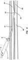
- Fig. 6illustrates a detail view of an alternate embodiment of jaw member 20 that is configured with two articulating elements 34, rather than a stationary element and an articulating element, as in the embodiment of Figs. 1-5 .
- an advantage of this embodimentis the ability to open the jaws 34 to a substantially wider extent than is the case with the first embodiment.
- the embodiment of Fig. 6is utilized in the same manner as is the embodiment of Figs. 1-5 .
Landscapes
- Health & Medical Sciences (AREA)
- Surgery (AREA)
- Life Sciences & Earth Sciences (AREA)
- Engineering & Computer Science (AREA)
- Heart & Thoracic Surgery (AREA)
- Medical Informatics (AREA)
- Otolaryngology (AREA)
- Plasma & Fusion (AREA)
- Physics & Mathematics (AREA)
- Biomedical Technology (AREA)
- Veterinary Medicine (AREA)
- Nuclear Medicine, Radiotherapy & Molecular Imaging (AREA)
- Molecular Biology (AREA)
- Animal Behavior & Ethology (AREA)
- General Health & Medical Sciences (AREA)
- Public Health (AREA)
- Cardiology (AREA)
- Neurology (AREA)
- Neurosurgery (AREA)
- Surgical Instruments (AREA)
Description
- In the body, various fluids are transported through conduits throughout the organism to perform various essential functions. Blood vessels, arteries, veins, and capillaries carry blood throughout the body, carrying nutrients and waste products to different organs and tissues for processing. Bile ducts carry bile from the liver to the duodenum. Ureters carry urine from the kidneys to the bladder. The intestines carry nutrients and waste products from the mouth to the anus.
- In medical practice, there is often a need to connect conduits to one another or to a replacement conduit to treat disease or dysfunction of the existing conduits. The connection created between conduits is called an anastomosis.
- In blood vessels, anastomoses are made between veins and arteries, arteries and arteries, or veins and veins. The purpose of these connections is to create either a high flow connection, or fistula, between an artery and a vein, or to carry blood around an obstruction in a replacement conduit, or bypass. The conduit for a bypass is a vein, artery, or prosthetic graft.
- An anastomosis is created during surgery by bringing two vessels or a conduit into direct contact, and to create a leak-free blood flow path between them. The vessels are joined together with suture or clips, in an open surgical procedure. The anastomosis can be end-to-end, end-to-side, or side-to-side. In blood vessels, the anastomosis is elliptical in shape and is most commonly sewn by hand with a continuous suture. Other methods for anastomosis creation have been used including carbon dioxide laser, and a number of methods using various connecting prosthesis, clips, and stents. Such procedures are time consuming, clinician dependent (open to surgical error), and often result in strictures, or clotting of the vein or artery.
- An arterio-venous fistula (AVF) is created by connecting an artery to a vein. This type of connection is used for hemodialysis, to increase exercise tolerance, to keep an artery or vein open, or to provide reliable access for chemotherapy.
- An alternative is to connect a prosthetic graft from an artery to a vein for the same purpose of creating a high flow connection between artery and vein. This is called an arterio-venous graft, and requires two anastomoses. One is between artery and graft, and the second is between graft and vein.
- A bypass is similar to an arteriovenous graft. To bypass an obstruction, two anastomoses and a conduit are required. A proximal anastomosis is created from a blood vessel to a conduit. The conduit extends around the obstruction, and a second distal anastomosis is created between the conduit and vessel beyond the obstruction.
- As noted above, in current medical practice, it is desirable to connect arteries to veins to create a fistula for the purpose of hemodialysis. The process of hemodialysis requires the removal of blood from the body at a rapid rate, passing the blood through a dialysis machine, and returning the blood to the body. The access to the blood circulation is achieved with catheters placed in large veins, prosthetic grafts attached to an artery and a vein, or a fistula where an artery is attached directly to the vein.
- Fistulas for hemodialysis are required by patients with kidney failure. The fistula provides a high flow of blood that can be withdrawn from the body into a dialysis machine to remove waste products and then returned to the body. The blood is withdrawn through a large access needle near the artery and returned to the fistula through a second large return needle. These fistulas are typically created in the forearm, upper arm, less frequently in the thigh, and in rare cases, elsewhere in the body. It is important that the fistula be able to achieve a flow rate of 500 ml per minute or greater. Dialysis fistulas have to be close to the skin (< 6 mm), and large enough (> 4 mm) to access with a large needle. The fistula needs to be long enough (> 6 cm) to allow adequate separation of the access and return needle to prevent recirculation of dialysed and non-dialysed blood between the needles inserted in the fistula.
- Fistulas are created in anesthetized patients by carefully dissecting an artery and vein from their surrounding tissue, and sewing the vessels together with fine suture or clips. The connection thus created is an anastomosis. It is highly desirable to be able to make the anastomosis quickly, reliably, with less dissection, and with less pain. It is important that the anastomosis is the correct size, is smooth, and that the artery and vein are not twisted.
US 2009/023985 ,US 6139508 &US 2005/143763 all disclose devices for carrying out intraluminal surgical procedures comprising a control handle, an elongate body portion and instrumentation located at the end of the body portion for carrying out the procedure.US 6443973 discloses an electromechanical device for carrying out surgical procedures comprising an elongate drive shaft, a motor located within a handle actuated by a trigger and instrumentation located at one end of the drive shaft.US 5,626,608 A describes a surgical instrument having a locking handle.JP H10 277050 A US 5,571,136 A describes forceps with a guide wire. - The invention is defined in claim 1. Further aspects and preferred embodiments are defined in the appended claims.
The present invention comprises a device to allow extension, elongation or repair of a previously created arteriovenous fistula between a first blood vessel and an adjacent second blood vessel which comprises a main body having a primary lumen and an articulating jaw member disposed at the distal end of the main body and configured with two elements to allow rotation of one element about a pivot point to grasp tissue while being rotated. The jaw member is also configured to allow thermal energy delivery to one or both elements of the jaw member that allow tissue welding and cutting with DC, RF, Laser or Ultrasonic energy. A second lumen located within one element of the jaw member is configured to allow advancement over a guidewire into the second vessel while the other element of the jaw member remains within the first blood vessel at the position where the arteriovenous fistula, or aperture, exists between the first and second blood vessel. - In one embodiment, the articulating jaw member is configured to allow rotation of both elements about a pivot point to grasp tissue and apply thermal energy.
- In an example, a method (not claimed) of elongation of the passage between adjacent first and second blood vessels comprises a step of positioning a main body of the device within the first vessel and advancing one element of the jaw member through the aperture between the vessels, and into the second vessel, so that the jaw element is disposed within the second vessel. The articulating element is actuated to rotate about the pivot point of the jaw member for grasping and compressing tissue adjacent to the aperture between the first blood vessel and the adjacent second blood vessel.
- The method further comprises the step of applying thermal energy to one or both elements of the jaw member to cut an extension to the aperture and weld the adjacent first and second blood vessel using DC, RF, Laser or ultrasonic energy.
- More particularly, there is provided in one aspect of the invention a device for elongating, extending, or repairing a tissue aperture, which comprises a handle, a body connected to and extending distally from the handle, comprised of a flexible material and having a primary lumen, a rigid jaw member connected to and extending distally from the flexible body, and a tissue cutting element disposed on the jaw member. Preferably, the flexible material comprising the body is a polymer having a Shore A hardness of 70-90. The rigid jaw member is preferably fabricated of a rigid material comprising either a metal or a rigid polymer having a Shore A hardness greater than 90, though, of course, other equivalent materials may be utilized alternatively, in both instances.
- The jaw member comprises two elements, each having distal ends, wherein one of the elements is pivotable relative to the other element to create a spacing of varying sizes between the two elements at their respective distal ends. In one of the disclosed embodiments, one of the elements is a stationary element and the other element is an articulating element, the articulating element being pivotable about a pivot point disposed on a proximal end thereof. In another disclosed alternative embodiment, both of the elements are articulating elements.
- In the disclosed embodiments, the tissue cutting element comprises an electrode for energizing the tissue to be cut. Two electrodes are illustrated in the drawings. A power supply and an activation switch are disposed on the handle for activating the electrode(s). The supplied energy may be thermal energy, RF energy, laser energy, ultrasonic energy, or the like.
- A lever is provided on the handle for moving at least one of the jaw member elements relative to the other one to increase or decrease the spacing between the distal ends of the elements, thereby opening or closing the jaws of the jaw member. As disclosed, a wire connects the lever to the jaw member for opening or closing the jaw member. A ratcheting mechanism is provided on the lever for applying variable incremental pressure to the jaw member.
- A conductor connects the power supply and activation switch to the electrode. The electrode may be comprised of aluminum or other suitable conductive material. A secondary lumen is disposed in one of the jaw elements.
- The jaw member has a closed orientation wherein both jaw elements are substantially aligned with a longitudinal axis of the primary lumen, and open orientations wherein at least one of the jaw elements is disposed at a substantial angle of varying sizes from the longitudinal axis of the primary lumen.
- In an example, there is disclosed a method (not claimed) of extending, elongating, or repairing a fistula between adjacent first and second vessels. The method comprises a step of inserting a main body of a device into the first vessel so that a distal end thereof lies within a blood flow passage of the first vessel. A jaw member disposed at a distal end of the main body is opened, and the open jaw member is disposed so that a portion of tissue adjacent to the fistula is disposed between elements thereof. The elements of the jaw member are closed to clamp the portion of tissue therebetween. An electrode on the jaw member is energized to cut and weld the tissue to extend the fistula. The device is then withdrawn from the site.
- The inserting step may further comprise a step of aligning a lumen in the main body over a guidewire, and sliding the device over the guidewire to the desired location. The energizing step may comprise applying thermal energy of about 10-50 watts to the clamped tissue. During the energizing step, the tissue temperature is increased to about 100-400 degrees C to cut and weld an extended aperture of about 1-5 mm from the primary blood vessel to the secondary blood vessel.
- Imaging guidance is preferably used to insert the device into a procedural site and monitor the cutting and welding step.
- The invention, together with additional features and advantages thereof, may best be understood by reference to the following description taken in conjunction with the accompanying illustrative drawings.
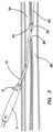
Fig. 1 is a view of one embodiment of the device of the present invention, wherein the device has been percutaneously or surgically positioned at a desired location in a blood vessel near the arteriovenous fistula;Fig. 2 is a view illustrating the distal jaw member in isolation;Fig. 3 is a view similar toFig. 1 , wherein one element of the jaw member illustrated inFig. 2 has been advanced over the guidewire into the second blood vessel while the second element has been articulated to the open position within the first blood vessel;Fig. 4 is a view similar toFig. 3 , wherein the second element of the jaw member is articulated from the open to closed position to grasp tissue and cut and weld an extension to the arteriovenous fistula aperture;Fig. 5 illustrates the extended communicating aperture created by the device and methods of the present invention after the inventive device ofFigs. 1-4 has been withdrawn from the procedural site; andFig. 6 illustrates an alternate embodiment of the distal jaw member.- Referring now more particularly to the drawings, one embodiment of a device constructed in accordance with the principles of the present invention is shown. As illustrated in
Figs. 1 and2 , a device 1 comprises ahandle 2 with anactivation switch 4, an electrical connector 6, and ajaw lever 8. A 4-7 F (French) flexible (70-90 Shore A) polymermain body 12, having aprimary lumen 14 and rigiddistal jaw member 20, is provided. The main body is attached to thehandle 2 at the proximal end and thejaw member 20 at the distal end. The electrical connector 6 allows connection to temperature display and power supply devices for temperature feedback and DC thermal energy delivery, though other modalities such as Radio Frequency (RF) or laser are can be employed.Lever 8 is constructed with a ratcheting mechanism to allow variable incremental pressure (approximately 100 mN/mm2 - 500 mN/mm2) toelectrodes 22 on jaw member 20 (Fig. 2 ) as desired by the practitioner. To begin the inventive method of intravascular arteriovenous fistula extension or elongation, the practitioner selects an appropriate procedural site having each of afirst blood vessel 24 and asecond blood vessel 26 in close proximity to one another and having a previously createdarteriovenous fistula 28 disposed therebetween (Fig. 3 ). In currently preferred approaches, thefirst blood vessel 24 comprises a vein, and thesecond blood vessel 26 comprises an artery, but the invention is not limited to this arrangement. Under real time imaging guidance such as ultrasound or fluoroscopy, themain body 12 is inserted into thefirst vessel 24 so that adistal end 32 thereof lies within the blood flow passage of the first vessel . Preferably, this insertion step is performed using percutaneous technique, but open surgery and direct visualization may also be employed. - With reference now particularly to
Fig. 2 , thejaw member 20 comprises an articulatingelement 34 and astationary element 36, including asecondary lumen 38. The articulatingelement 34 is movable about apivot point 40, and is attached to atendon wire 42, as illustrated. It should be noted that the invention is not limited to a single articulatingelement 34,pivot point 40, andtendon wire 42, though only one of each is shown in this particular embodiment. Articulatingelement 34 andstationary element 36 are preferably constructed of a rigid material such as metal or rigid (>90 Shore A) polymer, with 1-5 mm elongate electrodes 44 attached to the opposing surfaces. Electrodes 44, preferably constructed of an electrically and thermally conductive material, such as aluminum, are attached to the electrical connector 6 onhandle 2 viaconductors 46, which are preferably constructed of an electrically and thermally conductive material such as copper. Atemperature sensor 48, such as a thermocouple or thermistor, is attached to thestationary element 36 on one end and the electrical connector 6 on the opposite end.Tendon wire 42, preferably constructed of 18-24 Ga (Gauge) wire, is attached to the articulatingelement 34 on one end and to thejaw lever 8 on the other end.Stationary element 36 includes thesecondary lumen 38, as noted above. These elements, including theprimary lumen 14 of themain body shaft 12, provide an externally communicating passage to allow advancement of the device 1 over aguidewire 50. - Referring now particularly to
Figs. 2 and3 , the orientation of the articulatingelement 34 of thejaw member 20 can be rotationally adjustable between a range of rotation about thepivot point 40. A first, or closed, position is illustrated inFig. 2 where the articulatingelement 34 is substantially aligned with thelongitudinal axis 52 of theprimary lumen 14 and thesecondary lumen 38. As will be described more fully below, the closed orientation is utilized during the initial device insertion steps, as well as the device withdrawal steps, while variable rotated orientations are the operative for creating the extension or elongation of thearteriovenous fistula 28. This variable orientation may be desirable by the practitioner to incrementally adjust the opening of thejaw member 20 to achieve an optimal size extension of theaperture 28 betweenprimary vessel 24 andsecondary vessel 26. - Referring again to
Fig. 3 , once themain body 12 is inserted into thefirst vessel 24 and advanced to the desired site determined by the practitioner using ultrasound or fluoroscopic imaging, as previously described, it may be desired to adjust the rotation of the articulatingelement 34 to increase the angle of the opening ofjaw member 20, by rotating thelever 8 ofmain body handle 2. Since thejaw member 20 is configured to have echogenic and radiopaque properties to allow the practitioner to visualize the orientation under real time imaging guidance, this will allow the practitioner to more effectively adjust the opening ofjaw member 20 through direct visualization as it is advanced into the desired position in thearteriovenous fistula aperture 28 between theprimary blood vessel 24 and thesecondary blood vessel 26 to achieve the desired length of extension of the aperture. This step may be repeated as desired by thepractitioner rotating lever 8 of main body handle 2 to adjust the open position of articulatingelement 34, until the desired arteriovenous fistula aperture extension has been achieved. - With reference now to
Fig. 4 , once the practitioner has oriented thestationary element 36 of thejaw member 20 as desired through thearteriovenous fistula aperture 28 and withinsecondary blood vessel 26, thelever 8 of thehandle 2 is rotated to the fully closed position to compress the blood vessels within thejaw member 20.Activation switch 4 is activated to deliver thermal energy of between about 10 -50 W to thejaws 20, sufficient to raise the tissue temperature to about 100-400 degrees C to cut and weld anextended aperture 28 of 1-5mm from theprimary blood vessel 24 to thesecondary blood vessel 26. This may be done under direct imaging guidance to verify energy delivery in the area desired by the practitioner, due to the creation of micro bubbles visible under transcutaneous ultrasound in the area of direct thermal energy. The practitioner may also verify acceptable extension of the aperture through direct visualization of the larger opening in the aperture under imaging guidance. - With reference now to
Fig. 5 , once the extension ofarteriovenous fistula aperture 28 fromprimary blood vessel 24 tosecondary blood vessel 26 has been achieved as previously described, the practitioner withdraws device 1 completely from the body, thus leaving anextended aperture 28 in the anastomosis between theprimary vessel 24 and thesecondary vessel 26. Fig. 6 illustrates a detail view of an alternate embodiment ofjaw member 20 that is configured with two articulatingelements 34, rather than a stationary element and an articulating element, as in the embodiment ofFigs. 1-5 . As is evident to those skilled in the art, an advantage of this embodiment is the ability to open thejaws 34 to a substantially wider extent than is the case with the first embodiment. In all other respects, the embodiment ofFig. 6 is utilized in the same manner as is the embodiment ofFigs. 1-5 .
Claims (9)
- A device (1) for elongating, extending, or repairing an arteriovenous fistula between a first blood vessel and an adjacent second blood vessel, comprising:a handle (2);a body (12) connected to and extending distally from the handle (2), comprised of a flexible material and having a primary lumen (14);a rigid jaw member (20) connected to and extending distally from the flexible body (12), the jaw member (20) including two elements (34, 36) each having distal ends, wherein one of the elements (34, 36) is pivotable relative to the other element (34, 36) to create a spacing of varying sizes between the two elements at their respective distal ends;a tissue cutting element (22) disposed on the jaw member (20);a lever (8) on the handle (2) for moving at least one of the jaw member elements (34, 36) relative to the other one to increase or decrease the spacing between the distal ends of the elements (34, 36), thereby opening or closing the jaws of the jaw member (20);a ratcheting mechanism on said lever (8) for applying variable incremental pressure to the jaw member (20);characterized bya wire (42) connecting the lever (8) to the jaw member (20) for opening or closing the jaw member (20); anda secondary lumen (38) disposed in one of the jaw elements (20).
- The device as recited in Claim 1, wherein the flexible material comprising the body (12) is a polymer.
- The device as recited in Claim 2, wherein the polymer comprising the body (12) has a Shore A hardness of 70-90.
- The device as recited in Claim 1, wherein the rigid jaw member (20) is fabricated of a rigid material comprising either a metal or a rigid polymer having a Shore A hardness greater than 90.
- The device as recited in Claim 1, wherein one of the elements is a stationary element (36) and the other element is an articulating element (14), the articulating element (34) being pivotable about a pivot point (40) disposed on a proximal end thereof.
- The device as recited in Claim 1, wherein the tissue cutting element comprises an electrode (22) for energizing the tissue to be cut.
- The device as recited in Claim 6, and further comprising a power supply and an activation switch (4) disposed on the handle (2) for activating said electrode (22).
- The device as recited in Claim 7, and further comprising a conductor (46) for electrically connecting the power supply and activation switch (4) to the electrode (22).
- The device as recited in Claim 1, wherein the jaw member (20) has a closed orientation wherein both jaw elements are substantially aligned with a longitudinal axis of the primary lumen (14), and open orientations wherein at least one of the jaw elements is disposed at a substantial angle of varying sizes from the longitudinal axis of the primary lumen (14).
Applications Claiming Priority (2)
| Application Number | Priority Date | Filing Date | Title |
|---|---|---|---|
| US201261678240P | 2012-08-01 | 2012-08-01 | |
| PCT/US2013/053070WO2014022585A1 (en) | 2012-08-01 | 2013-07-31 | Systems and methods for percutaneous intravascular access for arteriovenous fistula |
Publications (3)
| Publication Number | Publication Date |
|---|---|
| EP2879753A1 EP2879753A1 (en) | 2015-06-10 |
| EP2879753A4 EP2879753A4 (en) | 2016-05-04 |
| EP2879753B1true EP2879753B1 (en) | 2025-04-16 |
Family
ID=50026191
Family Applications (1)
| Application Number | Title | Priority Date | Filing Date |
|---|---|---|---|
| EP13824823.2AActiveEP2879753B1 (en) | 2012-08-01 | 2013-07-31 | Systems for percutaneous intravascular access for arteriovenous fistula |
Country Status (6)
| Country | Link |
|---|---|
| US (2) | US20140039478A1 (en) |
| EP (1) | EP2879753B1 (en) |
| JP (1) | JP6634288B2 (en) |
| AU (1) | AU2013296428B2 (en) |
| CA (1) | CA2880253C (en) |
| WO (1) | WO2014022585A1 (en) |
Families Citing this family (6)
| Publication number | Priority date | Publication date | Assignee | Title |
|---|---|---|---|---|
| US10292708B1 (en) | 2014-02-13 | 2019-05-21 | Avenu Medical, Inc. | Externally supported anastomosis |
| US10772672B2 (en) | 2014-03-06 | 2020-09-15 | Avenu Medical, Inc. | Systems and methods for percutaneous access and formation of arteriovenous fistulas |
| CN108366822B (en) | 2015-08-21 | 2021-02-19 | 艾凡诺医疗公司 | System and method for percutaneous arteriovenous fistula |
| WO2018213626A1 (en)* | 2017-05-17 | 2018-11-22 | Avenu Medical, Inc. | Single catheter electrode tissue cutting system for creating anastomoses |
| CN111714189B (en)* | 2020-06-30 | 2022-08-12 | 十堰市太和医院(湖北医药学院附属医院) | Vascular fistula surgical opening |
| EP4074352A1 (en) | 2021-04-12 | 2022-10-19 | Mallios Consulting | Devices for forming percutaneous vascular anastomosis, in particular percutaneous arteriovenous fistula for hemodialysis |
Citations (5)
| Publication number | Priority date | Publication date | Assignee | Title |
|---|---|---|---|---|
| US5571136A (en)* | 1994-08-15 | 1996-11-05 | Medical Innovations Corporation | Forceps with guide wire |
| US5626608A (en)* | 1996-03-29 | 1997-05-06 | United States Surgical Corporation | Surgical instrument having locking handle |
| JPH10277050A (en)* | 1997-04-04 | 1998-10-20 | Olympus Optical Co Ltd | High-frequency treating implement for endscope |
| JP2002011019A (en)* | 2000-06-27 | 2002-01-15 | Inprest Co Ltd | Forceps with ratchet system |
| US20060217706A1 (en)* | 2005-03-25 | 2006-09-28 | Liming Lau | Tissue welding and cutting apparatus and method |
Family Cites Families (25)
| Publication number | Priority date | Publication date | Assignee | Title |
|---|---|---|---|---|
| US4251310A (en)* | 1977-11-25 | 1981-02-17 | Baxter Travenol Laboratories, Inc. | Method for rebonding tubing elements used in needle assemblies |
| US4863441A (en)* | 1987-07-17 | 1989-09-05 | Minnesota Mining And Manufacturing Company | Venous return catheter |
| US6066102A (en)* | 1998-03-09 | 2000-05-23 | Spectrascience, Inc. | Optical biopsy forceps system and method of diagnosing tissue |
| US6139508A (en)* | 1998-08-04 | 2000-10-31 | Endonetics, Inc. | Articulated medical device |
| US6443973B1 (en) | 1999-06-02 | 2002-09-03 | Power Medical Interventions, Inc. | Electromechanical driver device for use with anastomosing, stapling, and resecting instruments |
| US7892246B2 (en)* | 1999-07-28 | 2011-02-22 | Bioconnect Systems, Inc. | Devices and methods for interconnecting conduits and closing openings in tissue |
| JP4166016B2 (en)* | 2000-01-04 | 2008-10-15 | メドトロニック ヴァスキュラー インコーポレイテッド | A device that forms a pathway between adjacent body lumens |
| US6361540B1 (en)* | 2000-04-06 | 2002-03-26 | Michael W. L. Gauderer | Apparatus for removal of esophageal coins and similarly shaped objects |
| US7331968B2 (en)* | 2004-06-14 | 2008-02-19 | Ethicon Endo-Surgery, Inc. | Endoscopic clip applier with threaded clip |
| EP1795140B1 (en)* | 2002-10-04 | 2017-02-22 | Covidien AG | Electrode assembly for sealing and cutting tissue |
| WO2004050144A2 (en)* | 2002-12-04 | 2004-06-17 | Angiodynamics, Inc. | Variable characteristic venous access catheter |
| US7618427B2 (en)* | 2003-12-29 | 2009-11-17 | Ethicon Endo-Surgery, Inc. | Device and method for intralumenal anastomosis |
| US7955332B2 (en)* | 2004-10-08 | 2011-06-07 | Covidien Ag | Mechanism for dividing tissue in a hemostat-style instrument |
| US7892208B2 (en)* | 2006-07-28 | 2011-02-22 | Dsu Medical Corporation | Medical tubing set sheath |
| US20080051626A1 (en)* | 2006-08-28 | 2008-02-28 | Olympus Medical Systems Corp. | Fistulectomy method between first duct and second duct, ultrasonic endoscope, catheter with balloon, magnet retaining device, and magnet set |
| US20090023985A1 (en)* | 2007-06-14 | 2009-01-22 | Usgi Medical, Inc. | Endoluminal instrument management system |
| GB0804688D0 (en)* | 2008-03-13 | 2008-04-16 | Gyrus Group Plc | Surgical instrument |
| US7875029B1 (en)* | 2009-05-04 | 2011-01-25 | Cardica, Inc. | Surgical device switchable between clip application and coagulation modes |
| US20100324446A1 (en)* | 2009-06-18 | 2010-12-23 | Vance Products Incorporated, D/B/A Cook Orolgoical Incorporated | Telescoping Biopsy Device |
| US8591459B2 (en)* | 2009-12-21 | 2013-11-26 | Ethicon Endo-Surgery, Inc. | Use of biomarkers and therapeutic agents with surgical devices |
| WO2011159825A1 (en)* | 2010-06-15 | 2011-12-22 | Caymus Medical, Inc. | Intravascular arterial to venous anastomosis and tissue welding catheter |
| US8663222B2 (en)* | 2010-09-07 | 2014-03-04 | Covidien Lp | Dynamic and static bipolar electrical sealing and cutting device |
| US9463269B2 (en)* | 2010-09-10 | 2016-10-11 | W. L. Gore & Associates, Inc. | Anastomotic devices and methods |
| JP5191615B2 (en)* | 2010-09-23 | 2013-05-08 | オリンパスメディカルシステムズ株式会社 | Bend catheter |
| US8690902B2 (en)* | 2010-11-04 | 2014-04-08 | Ethicon Endo-Surgery, Inc. | Method of enlarging an anastomosis fistula into a larger anastomosis |
- 2013
- 2013-07-31EPEP13824823.2Apatent/EP2879753B1/enactiveActive
- 2013-07-31AUAU2013296428Apatent/AU2013296428B2/enactiveActive
- 2013-07-31WOPCT/US2013/053070patent/WO2014022585A1/enactiveIP Right Grant
- 2013-07-31CACA2880253Apatent/CA2880253C/enactiveActive
- 2013-07-31USUS13/956,221patent/US20140039478A1/ennot_activeAbandoned
- 2013-07-31JPJP2015525567Apatent/JP6634288B2/enactiveActive
- 2015
- 2015-11-17USUS14/944,090patent/US10238449B2/enactiveActive
Patent Citations (5)
| Publication number | Priority date | Publication date | Assignee | Title |
|---|---|---|---|---|
| US5571136A (en)* | 1994-08-15 | 1996-11-05 | Medical Innovations Corporation | Forceps with guide wire |
| US5626608A (en)* | 1996-03-29 | 1997-05-06 | United States Surgical Corporation | Surgical instrument having locking handle |
| JPH10277050A (en)* | 1997-04-04 | 1998-10-20 | Olympus Optical Co Ltd | High-frequency treating implement for endscope |
| JP2002011019A (en)* | 2000-06-27 | 2002-01-15 | Inprest Co Ltd | Forceps with ratchet system |
| US20060217706A1 (en)* | 2005-03-25 | 2006-09-28 | Liming Lau | Tissue welding and cutting apparatus and method |
Also Published As
| Publication number | Publication date |
|---|---|
| WO2014022585A1 (en) | 2014-02-06 |
| JP2015524313A (en) | 2015-08-24 |
| CA2880253A1 (en) | 2014-02-06 |
| EP2879753A4 (en) | 2016-05-04 |
| US10238449B2 (en) | 2019-03-26 |
| CA2880253C (en) | 2020-07-28 |
| US20160135873A1 (en) | 2016-05-19 |
| JP6634288B2 (en) | 2020-01-22 |
| AU2013296428B2 (en) | 2017-05-25 |
| US20140039478A1 (en) | 2014-02-06 |
| EP2879753A1 (en) | 2015-06-10 |
| AU2013296428A1 (en) | 2015-02-19 |
Similar Documents
| Publication | Publication Date | Title |
|---|---|---|
| US11690944B2 (en) | Systems and methods for creating arteriovenous (AV) fistulas | |
| US11950828B2 (en) | Intravascular arterial to venous anastomosis and tissue welding catheter | |
| US11083518B2 (en) | Intravascular arterial to venous anastomosis and tissue welding catheter and methods | |
| US10238449B2 (en) | Systems and methods for percutaneous intravascular access for arteriovenous fistula | |
| US9955972B1 (en) | Systems and methods for creating arteriovenous (AV) fistulas | |
| AU2015200498B2 (en) | Systems and methods for creating arteriovenous (AV) fistulas |
Legal Events
| Date | Code | Title | Description |
|---|---|---|---|
| PUAI | Public reference made under article 153(3) epc to a published international application that has entered the european phase | Free format text:ORIGINAL CODE: 0009012 | |
| 17P | Request for examination filed | Effective date:20150219 | |
| AK | Designated contracting states | Kind code of ref document:A1 Designated state(s):AL AT BE BG CH CY CZ DE DK EE ES FI FR GB GR HR HU IE IS IT LI LT LU LV MC MK MT NL NO PL PT RO RS SE SI SK SM TR | |
| AX | Request for extension of the european patent | Extension state:BA ME | |
| DAX | Request for extension of the european patent (deleted) | ||
| RA4 | Supplementary search report drawn up and despatched (corrected) | Effective date:20160404 | |
| RIC1 | Information provided on ipc code assigned before grant | Ipc:A61M 25/14 20060101AFI20160329BHEP Ipc:A61M 25/09 20060101ALI20160329BHEP | |
| STAA | Information on the status of an ep patent application or granted ep patent | Free format text:STATUS: EXAMINATION IS IN PROGRESS | |
| 17Q | First examination report despatched | Effective date:20201027 | |
| GRAP | Despatch of communication of intention to grant a patent | Free format text:ORIGINAL CODE: EPIDOSNIGR1 | |
| STAA | Information on the status of an ep patent application or granted ep patent | Free format text:STATUS: GRANT OF PATENT IS INTENDED | |
| INTG | Intention to grant announced | Effective date:20241120 | |
| GRAS | Grant fee paid | Free format text:ORIGINAL CODE: EPIDOSNIGR3 | |
| GRAA | (expected) grant | Free format text:ORIGINAL CODE: 0009210 | |
| STAA | Information on the status of an ep patent application or granted ep patent | Free format text:STATUS: THE PATENT HAS BEEN GRANTED | |
| AK | Designated contracting states | Kind code of ref document:B1 Designated state(s):AL AT BE BG CH CY CZ DE DK EE ES FI FR GB GR HR HU IE IS IT LI LT LU LV MC MK MT NL NO PL PT RO RS SE SI SK SM TR | |
| REG | Reference to a national code | Ref country code:GB Ref legal event code:FG4D | |
| REG | Reference to a national code | Ref country code:CH Ref legal event code:EP | |
| REG | Reference to a national code | Ref country code:IE Ref legal event code:FG4D | |
| REG | Reference to a national code | Ref country code:DE Ref legal event code:R096 Ref document number:602013086684 Country of ref document:DE | |
| PGFP | Annual fee paid to national office [announced via postgrant information from national office to epo] | Ref country code:FR Payment date:20250620 Year of fee payment:13 | |
| REG | Reference to a national code | Ref country code:NL Ref legal event code:MP Effective date:20250416 | |
| PG25 | Lapsed in a contracting state [announced via postgrant information from national office to epo] | Ref country code:NL Free format text:LAPSE BECAUSE OF FAILURE TO SUBMIT A TRANSLATION OF THE DESCRIPTION OR TO PAY THE FEE WITHIN THE PRESCRIBED TIME-LIMIT Effective date:20250416 | |
| REG | Reference to a national code | Ref country code:AT Ref legal event code:MK05 Ref document number:1785145 Country of ref document:AT Kind code of ref document:T Effective date:20250416 | |
| PG25 | Lapsed in a contracting state [announced via postgrant information from national office to epo] | Ref country code:PT Free format text:LAPSE BECAUSE OF FAILURE TO SUBMIT A TRANSLATION OF THE DESCRIPTION OR TO PAY THE FEE WITHIN THE PRESCRIBED TIME-LIMIT Effective date:20250818 Ref country code:FI Free format text:LAPSE BECAUSE OF FAILURE TO SUBMIT A TRANSLATION OF THE DESCRIPTION OR TO PAY THE FEE WITHIN THE PRESCRIBED TIME-LIMIT Effective date:20250416 Ref country code:ES Free format text:LAPSE BECAUSE OF FAILURE TO SUBMIT A TRANSLATION OF THE DESCRIPTION OR TO PAY THE FEE WITHIN THE PRESCRIBED TIME-LIMIT Effective date:20250416 | |
| REG | Reference to a national code | Ref country code:LT Ref legal event code:MG9D |