EP2878362B1 - Capillary dialyzers - Google Patents
Capillary dialyzersDownload PDFInfo
- Publication number
- EP2878362B1 EP2878362B1EP13195276.4AEP13195276AEP2878362B1EP 2878362 B1EP2878362 B1EP 2878362B1EP 13195276 AEP13195276 AEP 13195276AEP 2878362 B1EP2878362 B1EP 2878362B1
- Authority
- EP
- European Patent Office
- Prior art keywords
- section
- housing
- sections
- internal chamber
- hollow fiber
- Prior art date
- Legal status (The legal status is an assumption and is not a legal conclusion. Google has not performed a legal analysis and makes no representation as to the accuracy of the status listed.)
- Active
Links
- 239000012528membraneSubstances0.000claimsdescription33
- 239000012510hollow fiberSubstances0.000claimsdescription30
- 239000000463materialSubstances0.000claimsdescription15
- 238000004382pottingMethods0.000claimsdescription15
- 238000000034methodMethods0.000claimsdescription9
- 239000012530fluidSubstances0.000claimsdescription4
- 229920000098polyolefinPolymers0.000claimsdescription4
- 239000004743PolypropyleneSubstances0.000claimsdescription3
- -1polypropylenePolymers0.000claimsdescription3
- 229920001155polypropylenePolymers0.000claimsdescription3
- 238000005304joiningMethods0.000claimsdescription2
- 239000000835fiberSubstances0.000description6
- 238000004519manufacturing processMethods0.000description5
- 239000000853adhesiveSubstances0.000description4
- 230000001070adhesive effectEffects0.000description4
- 239000008280bloodSubstances0.000description4
- 210000004369bloodAnatomy0.000description4
- 230000032798delaminationEffects0.000description4
- 229920002635polyurethanePolymers0.000description4
- 239000004814polyurethaneSubstances0.000description4
- 238000000926separation methodMethods0.000description3
- 238000001631haemodialysisMethods0.000description2
- 230000000322hemodialysisEffects0.000description2
- 229920000642polymerPolymers0.000description2
- 238000000746purificationMethods0.000description2
- 238000007789sealingMethods0.000description2
- 208000001647Renal InsufficiencyDiseases0.000description1
- 230000015572biosynthetic processEffects0.000description1
- 238000005119centrifugationMethods0.000description1
- 150000001875compoundsChemical class0.000description1
- 238000005520cutting processMethods0.000description1
- 239000000385dialysis solutionSubstances0.000description1
- 238000002615hemofiltrationMethods0.000description1
- 201000006370kidney failureDiseases0.000description1
- 238000002844meltingMethods0.000description1
- 230000008018meltingEffects0.000description1
- 230000001954sterilising effectEffects0.000description1
- 238000004659sterilization and disinfectionMethods0.000description1
- 238000003466weldingMethods0.000description1
Images

Classifications
- A—HUMAN NECESSITIES
- A61—MEDICAL OR VETERINARY SCIENCE; HYGIENE
- A61M—DEVICES FOR INTRODUCING MEDIA INTO, OR ONTO, THE BODY; DEVICES FOR TRANSDUCING BODY MEDIA OR FOR TAKING MEDIA FROM THE BODY; DEVICES FOR PRODUCING OR ENDING SLEEP OR STUPOR
- A61M1/00—Suction or pumping devices for medical purposes; Devices for carrying-off, for treatment of, or for carrying-over, body-liquids; Drainage systems
- A61M1/14—Dialysis systems; Artificial kidneys; Blood oxygenators ; Reciprocating systems for treatment of body fluids, e.g. single needle systems for hemofiltration or pheresis
- A61M1/16—Dialysis systems; Artificial kidneys; Blood oxygenators ; Reciprocating systems for treatment of body fluids, e.g. single needle systems for hemofiltration or pheresis with membranes
- A61M1/1621—Constructional aspects thereof
- A61M1/1623—Disposition or location of membranes relative to fluids
- A61M1/1627—Dialyser of the inside perfusion type, i.e. blood flow inside hollow membrane fibres or tubes
- B—PERFORMING OPERATIONS; TRANSPORTING
- B01—PHYSICAL OR CHEMICAL PROCESSES OR APPARATUS IN GENERAL
- B01D—SEPARATION
- B01D63/00—Apparatus in general for separation processes using semi-permeable membranes
- B01D63/02—Hollow fibre modules
- B—PERFORMING OPERATIONS; TRANSPORTING
- B01—PHYSICAL OR CHEMICAL PROCESSES OR APPARATUS IN GENERAL
- B01D—SEPARATION
- B01D63/00—Apparatus in general for separation processes using semi-permeable membranes
- B01D63/02—Hollow fibre modules
- B01D63/021—Manufacturing thereof
- B01D63/022—Encapsulating hollow fibres
- B01D63/0222—Encapsulating hollow fibres using centrifugal forces
- B—PERFORMING OPERATIONS; TRANSPORTING
- B01—PHYSICAL OR CHEMICAL PROCESSES OR APPARATUS IN GENERAL
- B01D—SEPARATION
- B01D2313/00—Details relating to membrane modules or apparatus
- B01D2313/20—Specific housing
- B01D2313/205—Specific housing characterised by the shape
- B—PERFORMING OPERATIONS; TRANSPORTING
- B01—PHYSICAL OR CHEMICAL PROCESSES OR APPARATUS IN GENERAL
- B01D—SEPARATION
- B01D2313/00—Details relating to membrane modules or apparatus
- B01D2313/20—Specific housing
- B01D2313/206—Specific housing characterised by the material
- B01D2313/2061—Organic, e.g. polymeric material
Definitions
- the present inventionrelates to capillary dialyzers for blood purification, methods for their production and housings for the capillary dialyzers.
- Capillary dialyzersare widely used for blood purification in patients suffering from renal insufficiency, i.e., for treatment of the patients by hemodialysis, hemodiafiltration or hemofiltration.
- a multitude of different models of capillary dialyzersis commercially available.
- the devicesgenerally consist of a housing comprising a tubular section with end caps capping the mouths of the tubular section.
- a bundle of hollow fiber membranesis arranged in the housing in a way that a seal is provided between a first flow space formed by the fiber cavities and a second flow space surrounding the membranes on the outside.
- the sealgenerally is provided by end wall means within the housing formed by a polymer mass in which the ends of the hollow fiber membranes are embedded. Examples of such devices are disclosed in EP 0 844 015 A2 , EP 0 305 687 A1 , and WO 01/60477 A2 .
- the end walls and the dialyzer housinggenerally are comprised of different materials which also usually have different thermal expansion coefficients.
- temperature changes during manufacture or processing of the dialyzer, e.g. thermal sterilization, or pressure changes within the dialyzer during operationgenerate strain at the interface between the inner wall of the housing and the end wall means which may cause delamination of the end wall means from the housing and generate leaks.
- Thisis particularly the case for combinations of materials where the adhesive force between the respective materials is low, for instance, when a polypropylene housing is combined with polyurethane end wall means.
- GB 1 537 415 Adiscloses a tubular membrane separation device, e.g. for hemodialysis, comprising a bundle of fibers enclosed in a casing.
- the housinghas an annular chamber at each end having a number of circumferentially spaced passageways leading to the space surrounding the bundle and suitably provided by crennelations in the inner wall of said annular chamber.
- EP 1 323 462 A2discloses a filter device comprising an additional ring component.
- the ringprovides an interface inside the filter which enables the potting compound to adhere to the filter and create a seal between a first and second fluid compartment within the filter.
- An embedded region of the ringpossesses a detailed geometry which helps ensure that a delamination would be localized and unable to propagate from the first to the second compartment.
- US 4 686 039 Adiscloses a fluid separation module having tube sheets positioned in the end portions of the cylindrical shell forming the exterior of the separation module.
- the end portions of the cylindrical shellhave a plurality of spaced cuts extending longitudinally from the end of the shell to points spaced from the end of the shell, with the cuts dividing the end of the shell into a plurality of tabs.
- the present applicationrelates to a capillary dialyzer with a housing comprising a plurality of circumferential ridges in the zones where the end wall means which seal the individual compartments of the dialyzer from each other are located.
- the circumferential ridgesprovide additional anchors for the end wall means and prevent delamination of the end wall means from the inner surface of the housing.
- a dialyzer housing 4which comprises a cylindrical first section 1 having an inner diameter d 1 ; a cylindrical second section 2 coaxial with the first section 1 and having an inner diameter d 2 which is larger than d 1 ; and a third section 3 joining the first section 1 and the second section 2, wherein a plurality of circumferential ridges 5 having a tooth profile and pointing in the direction of the axis of the first section 1 away from the first section 1 are provided on the inner surface of the third section 3.
- the inner diameter d 1 of the first section 1is in the range of from 20 mm to 55 mm, for instance 25 to 50 mm.
- the difference of the diameters d 1 and d 2generally is in the range of from 5 mm to 15 mm.
- the height of the third section 3is in the range of from 0.36*(d 2 -d 1 ) to 2.75*(d 2 -d 1 ).
- the faces of the circumferential ridges 5form an angle in the range of from 20° to 40°.
- the circumferential ridges 5have an elevation relative to the inner wall surface of the third section 3, measured from the top of the ridge in axial direction, in the range of from 1 to 10 mm.
- the number of circumferential ridges 5is 2 to 5.
- the spacing of the tops of the individual circumferential ridges 5is in the range of from 0.5 to 3 mm.
- a plurality of openings 6 tapering from the outside towards the insideis provided in the wall of the second section 2.
- the openings 6have a diameter on the outside surface of the second section 2 in the range of from 1 to 4 mm.
- the first section 1comprises fluid ports 7.
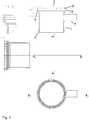
- Fig. 1shows different (partial) views of an exemplary embodiment of the housing 4 featuring four circumferential ridges 5 having a tooth profile (see, e.g., Detail B) and featuring a plurality of conical holes in the second section 2.
- the faces of the circumferential ridges 5form an angle of 30°; and the spacing of the tops of the individual circumferential ridges 5 is 1 mm.
- the dialyzer housing 4is comprised of a polyolefin.
- the polyolefinis polypropylene.
- the present applicationalso provides a capillary dialyzer comprising a housing 4 as described above and second sections 2 and third sections 3 as described above on each end of the first section 1.
- the housing 4defines a longitudinally extending internal chamber including a first end and a second end.
- a bundle 8 of semi-permeable hollow fiber membranesis disposed within the internal chamber and extends longitudinally from the first end of the internal chamber to the second end of the internal chamber.
- the hollow fiber membraneseach have an outer surface and a first end and a second end corresponding to the first end and the second end of the internal chamber.
- End wall means 9 supporting the first and second ends of the hollow fiber membranesare provided within the internal chamber so as to sealingly separate the first ends and second ends of the hollow fiber membranes from the outer surfaces of the hollow fiber membranes between the first ends and second ends thereof.
- the end wall meansfill the third sections 3.
- Each of the second sections 2features a plurality of openings 6 in its wall, tapering from the outside towards the inside of the wall; and the end wall means 9 also fill the openings 6 of the second sections 2.
- a longitudinal-sectional schematic view of such a dialyzeris shown in Fig. 2 .
- End wall means 9extend over both second sections 2 and third sections 3 and also fill the conical holes 6 in the wall of the second sections 2.
- An exemplary processcomprises the steps of providing a housing 4 as described above which comprises second sections 2 and third sections 3 on each end of the first section 1.
- the housing 4defines a longitudinally extending internal chamber including a first end and a second end.
- a bundle 8 of semi-permeable hollow fiber membranes having an outer surface, a first end and a second endis introduced into the internal chamber so that the bundle 8 extends longitudinally from the first end of the internal chamber to the second end of the internal chamber and the first ends and second ends of the hollow fiber membranes correspond to the first end and the second end of the internal chamber, respectively.
- End wall means 9 supporting the first and second ends of the hollow fiber membranesare provided within the internal chamber so as to sealingly separate the first ends and second ends of the hollow fiber membranes from the outer surface of the hollow fiber membranes between the first ends and second ends thereof, by introducing a potting material into the third sections 3 and second sections 2 of the housing 4 and filling the third sections 3 and the second sections 2 inclusive of the openings 6 in the wall of the second sections 2 with the potting material; and allowing the potting material to cure.
- the end wall means 9 supporting the first and second ends of the hollow fiber membranes within the internal chamberare generated by potting the ends of the fiber with a polymer.
- a suitable potting material for the hollow fiber membranesis polyurethane.
- the ends of the housing 4are closed and potting material, for instance polyurethane, is introduced into the housing 4 via one or both of the dialysis fluid ports 7.
- the potting materialis distributed within the housing 4 of the dialyzer by centrifugation, i.e., rotating the dialyzer at high speed perpendicular to its longitudinal axis.
- the potting materialis allowed to cure; thereby forming end wall means 9 on both ends of the bundle 8 of hollow fiber membranes.
- the potting materialshrinks during the curing process.
- the shrinkage of the cross-section of the end wall means 9generates a centripetal tensile force on the circumferential ridges 5 and the openings 6 in the wall of the second sections 2. This provides an additional lock between the end wall means 9 and the housing 4. It prevents detachment of the end wall means 9 from the inner wall of the housing 4 and thus the formation of leaks.
- the fiber endscan be closed by processes known in the art, e.g., by melting or by means of an adhesive. In one embodiment of the process, the ends of the hollow fiber membranes are closed before the bundle 8 of hollow fiber membranes is introduced into the housing 4.
- the ends of the hollow fiber membranesare subsequently opened, for instance by cutting part of the end wall means 9 with a blade.
- end caps featuring blood portsare mounted on the ends of the housing 4 of the dialyzer to close it.
- the end capsare bonded to the housing 4 by a suitable process, e.g., welding, heat-sealing, or by means of an adhesive, for instance, a polyurethane adhesive.
Landscapes
- Chemical & Material Sciences (AREA)
- Chemical Kinetics & Catalysis (AREA)
- Health & Medical Sciences (AREA)
- Engineering & Computer Science (AREA)
- Manufacturing & Machinery (AREA)
- Heart & Thoracic Surgery (AREA)
- Urology & Nephrology (AREA)
- Vascular Medicine (AREA)
- Emergency Medicine (AREA)
- Anesthesiology (AREA)
- Biomedical Technology (AREA)
- Hematology (AREA)
- Life Sciences & Earth Sciences (AREA)
- Animal Behavior & Ethology (AREA)
- General Health & Medical Sciences (AREA)
- Public Health (AREA)
- Veterinary Medicine (AREA)
- External Artificial Organs (AREA)
Description
- The present invention relates to capillary dialyzers for blood purification, methods for their production and housings for the capillary dialyzers.
- Capillary dialyzers are widely used for blood purification in patients suffering from renal insufficiency, i.e., for treatment of the patients by hemodialysis, hemodiafiltration or hemofiltration. A multitude of different models of capillary dialyzers is commercially available.
- The devices generally consist of a housing comprising a tubular section with end caps capping the mouths of the tubular section. A bundle of hollow fiber membranes is arranged in the housing in a way that a seal is provided between a first flow space formed by the fiber cavities and a second flow space surrounding the membranes on the outside. The seal generally is provided by end wall means within the housing formed by a polymer mass in which the ends of the hollow fiber membranes are embedded. Examples of such devices are disclosed in
EP 0 844 015 A2 ,EP 0 305 687 A1 , andWO 01/60477 A2 - It is important that the seal between the flow space formed by the fiber cavities and the flow space surrounding the membranes on the outside, i.e., the blood compartment and the dialysate compartment of the dialyzer, remains intact at all times, especially during operation of the dialyzer in the treatment of a patient. Often, additional parts like sealing rings, gaskets, and support rings are provided in the dialyzer as additional safeguards against leakage. Production, handling, and subsequent assembly of the additional elements add to the complexity of the production process and the manufacturing cost. It would therefore be desirable to dispense with these additional parts in the dialyzer.
- To this end, it is imperative that a tight connection between the end walls and the inner surface of the dialyzer housing is established and any delamination is prevented. The end walls and the dialyzer housing generally are comprised of different materials which also usually have different thermal expansion coefficients. As a consequence, temperature changes during manufacture or processing of the dialyzer, e.g. thermal sterilization, or pressure changes within the dialyzer during operation generate strain at the interface between the inner wall of the housing and the end wall means which may cause delamination of the end wall means from the housing and generate leaks. This is particularly the case for combinations of materials where the adhesive force between the respective materials is low, for instance, when a polypropylene housing is combined with polyurethane end wall means.
GB 1 537 415 AEP 1 323 462 A2US 4 686 039 A discloses a fluid separation module having tube sheets positioned in the end portions of the cylindrical shell forming the exterior of the separation module. The end portions of the cylindrical shell have a plurality of spaced cuts extending longitudinally from the end of the shell to points spaced from the end of the shell, with the cuts dividing the end of the shell into a plurality of tabs.- The present application relates to a capillary dialyzer with a housing comprising a plurality of circumferential ridges in the zones where the end wall means which seal the individual compartments of the dialyzer from each other are located. The circumferential ridges provide additional anchors for the end wall means and prevent delamination of the end wall means from the inner surface of the housing.
- The invention is defined in the appended claims.
- Fig. 1
- shows two longitudinal-sectional partial views and a top view of an embodiment of the dialyzer housing of the present application;
- Fig. 2
- shows a longitudinal-sectional schematic view of an embodiment of the capillary dialyzer of the present application.
- A
dialyzer housing 4 is provided which comprises a cylindricalfirst section 1 having an inner diameter d1; a cylindricalsecond section 2 coaxial with thefirst section 1 and having an inner diameter d2 which is larger than d1; and athird section 3 joining thefirst section 1 and thesecond section 2, wherein a plurality ofcircumferential ridges 5 having a tooth profile and pointing in the direction of the axis of thefirst section 1 away from thefirst section 1 are provided on the inner surface of thethird section 3. - In one embodiment, the inner diameter d1 of the
first section 1 is in the range of from 20 mm to 55 mm, for instance 25 to 50 mm. The difference of the diameters d1 and d2 generally is in the range of from 5 mm to 15 mm. In one embodiment of thedialyzer housing 4, the height of thethird section 3 is in the range of from 0.36*(d2-d1) to 2.75*(d2-d1). - In the
dialyzer housing 4, the faces of thecircumferential ridges 5 form an angle in the range of from 20° to 40°. Thecircumferential ridges 5 have an elevation relative to the inner wall surface of thethird section 3, measured from the top of the ridge in axial direction, in the range of from 1 to 10 mm. In one embodiment of thedialyzer housing 4, the number ofcircumferential ridges 5 is 2 to 5. In one embodiment of thedialyzer housing 4, the spacing of the tops of the individualcircumferential ridges 5 is in the range of from 0.5 to 3 mm. - In the
dialyzer housing 4, a plurality ofopenings 6 tapering from the outside towards the inside is provided in the wall of thesecond section 2. In one embodiment of thedialyzer housing 4, theopenings 6 have a diameter on the outside surface of thesecond section 2 in the range of from 1 to 4 mm. - In one embodiment of the
dialyzer housing 4, thefirst section 1 comprisesfluid ports 7.Fig. 1 shows different (partial) views of an exemplary embodiment of thehousing 4 featuring fourcircumferential ridges 5 having a tooth profile (see, e.g., Detail B) and featuring a plurality of conical holes in thesecond section 2. In this embodiment, the faces of thecircumferential ridges 5 form an angle of 30°; and the spacing of the tops of the individualcircumferential ridges 5 is 1 mm. - In one embodiment, the
dialyzer housing 4 is comprised of a polyolefin. In one embodiment, the polyolefin is polypropylene. - The present application also provides a capillary dialyzer comprising a
housing 4 as described above andsecond sections 2 andthird sections 3 as described above on each end of thefirst section 1. Thehousing 4 defines a longitudinally extending internal chamber including a first end and a second end. Abundle 8 of semi-permeable hollow fiber membranes is disposed within the internal chamber and extends longitudinally from the first end of the internal chamber to the second end of the internal chamber. The hollow fiber membranes each have an outer surface and a first end and a second end corresponding to the first end and the second end of the internal chamber. End wall means 9 supporting the first and second ends of the hollow fiber membranes are provided within the internal chamber so as to sealingly separate the first ends and second ends of the hollow fiber membranes from the outer surfaces of the hollow fiber membranes between the first ends and second ends thereof. The end wall means fill thethird sections 3. - Each of the
second sections 2 features a plurality ofopenings 6 in its wall, tapering from the outside towards the inside of the wall; and the end wall means 9 also fill theopenings 6 of thesecond sections 2. A longitudinal-sectional schematic view of such a dialyzer is shown inFig. 2 . End wall means 9 extend over bothsecond sections 2 andthird sections 3 and also fill theconical holes 6 in the wall of thesecond sections 2. - The present disclosure also relates to processes for producing the dialyzer of the invention. An exemplary process comprises the steps of providing a
housing 4 as described above which comprisessecond sections 2 andthird sections 3 on each end of thefirst section 1. Thehousing 4 defines a longitudinally extending internal chamber including a first end and a second end. Abundle 8 of semi-permeable hollow fiber membranes having an outer surface, a first end and a second end is introduced into the internal chamber so that thebundle 8 extends longitudinally from the first end of the internal chamber to the second end of the internal chamber and the first ends and second ends of the hollow fiber membranes correspond to the first end and the second end of the internal chamber, respectively. End wall means 9 supporting the first and second ends of the hollow fiber membranes are provided within the internal chamber so as to sealingly separate the first ends and second ends of the hollow fiber membranes from the outer surface of the hollow fiber membranes between the first ends and second ends thereof, by introducing a potting material into thethird sections 3 andsecond sections 2 of thehousing 4 and filling thethird sections 3 and thesecond sections 2 inclusive of theopenings 6 in the wall of thesecond sections 2 with the potting material; and allowing the potting material to cure. - The end wall means 9 supporting the first and second ends of the hollow fiber membranes within the internal chamber are generated by potting the ends of the fiber with a polymer. A suitable potting material for the hollow fiber membranes is polyurethane. In an exemplary process, the ends of the
housing 4 are closed and potting material, for instance polyurethane, is introduced into thehousing 4 via one or both of thedialysis fluid ports 7. The potting material is distributed within thehousing 4 of the dialyzer by centrifugation, i.e., rotating the dialyzer at high speed perpendicular to its longitudinal axis. The potting material is allowed to cure; thereby forming end wall means 9 on both ends of thebundle 8 of hollow fiber membranes. - The potting material shrinks during the curing process. The shrinkage of the cross-section of the end wall means 9 generates a centripetal tensile force on the
circumferential ridges 5 and theopenings 6 in the wall of thesecond sections 2. This provides an additional lock between the end wall means 9 and thehousing 4. It prevents detachment of the end wall means 9 from the inner wall of thehousing 4 and thus the formation of leaks. - It is expedient to close the ends of the hollow fiber membranes before the potting step in order to prevent the potting material from permeating into the fibers. The fiber ends can be closed by processes known in the art, e.g., by melting or by means of an adhesive. In one embodiment of the process, the ends of the hollow fiber membranes are closed before the
bundle 8 of hollow fiber membranes is introduced into thehousing 4. - The ends of the hollow fiber membranes are subsequently opened, for instance by cutting part of the end wall means 9 with a blade. After the ends of the hollow fiber membranes have been opened, end caps featuring blood ports are mounted on the ends of the
housing 4 of the dialyzer to close it. The end caps are bonded to thehousing 4 by a suitable process, e.g., welding, heat-sealing, or by means of an adhesive, for instance, a polyurethane adhesive.
Claims (10)
- A dialyzer housing (4) comprisingi) a cylindrical first section (1) having an inner diameter d1;ii) a cylindrical second section (2) coaxial with the first section (1) and having an inner diameter d2 which is larger than d1; wherein a plurality of openings (6) tapering from the outside towards the inside is provided in the wall of the second section (2); andiii) a third section (3) joining the first section (1) and the second section (2), wherein a plurality of circumferential ridges (5) are provided on the inner surface of the third section (3), each circumferential ridge (5) having a tooth profile and pointing in the direction of the axis of the first section (1) away from the first section (1), with the faces of the circumferential ridge (5) forming an angle in the range of from 20° to 40, and the circumferential ridge (5) having an elevation relative to the inner wall surface of the third section (3) in the range of from 1 to 10 mm .
- The dialyzer housing (4) of claim 1, wherein the height of the third section (3) is in the range of from 0.36*(d2-d1) to 2.75*(d2-d1).
- The dialyzer housing (4) of claim 1 or 2, wherein the number of circumferential ridges (5) is 2 to 5.
- The dialyzer housing (4) of claim 3, wherein the spacing of the tops of the individual circumferential ridges (5) is in the range of from 0.5 to 3 mm.
- The dialyzer housing (4) of any one of claims 1 to 4, wherein the openings (6) have a diameter on the outside surface of the second section (2) in the range of from 1 to 4 mm.
- The dialyzer housing (4) of any one of claims 1 to 5, wherein the first section (1) comprises fluid ports (7).
- The dialyzer housing (4) of any one of claims 1 to 6, which is comprised of a polyolefin.
- The dialyzer housing (4) of claim 7, wherein the polyolefin is polypropylene.
- A capillary dialyzer comprising:a) a housing (4) according to any one of claims 1 to 8, comprising second sections (2) and third sections (3) on each end of the first section (1), the housing (4) defining a longitudinally extending internal chamber including a first end and a second end;b) a bundle (8) of semi-permeable hollow fiber membranes disposed within the internal chamber and extending longitudinally from the first end of the internal chamber to the second end of the internal chamber, the hollow fiber membranes each having an outer surface, and a first end and a second end corresponding to the first end and the second end of the internal chamber;c) end wall means (9) supporting the first and second ends of the hollow fiber membranes within the internal chamber so as to sealingly separate the first ends and second ends of the hollow fiber membranes from the outer surfaces of the hollow fiber membranes between the first ends and second ends thereof, wherein the end wall means fill the third sections (3) and also fill the openings (6) of the second sections (2).
- A process for producing a capillary dialyzer, comprising:a) providing a housing (4) according to any one of claims 1 to 8, comprising second sections (2) and third sections (3) on each end of the first section (1), the housing (4) defining a longitudinally extending internal chamber including a first end and a second end;b) introducing a bundle (8) of semi-permeable hollow fiber membranes having an outer surface, a first end and a second end into the internal chamber so that the bundle (8) extends longitudinally from the first end of the internal chamber to the second end of the internal chamber and the first ends and second ends of the hollow fiber membranes correspond to the first end and the second end of the internal chamber, respectively;c) providing end wall means (9) supporting the first and second ends of the hollow fiber membranes within the internal chamber so as to sealingly separate the first ends and second ends of the hollow fiber membranes from the outer surface of the hollow fiber membranes between the first ends and second ends thereof, by introducing a potting material into the third sections (3) and second sections (2) of the housing (4) and filling the third sections (3) and the second sections (2) inclusive of the openings (6) in the wall of the second sections (2) with the potting material; and allowing the potting material to cure.
Priority Applications (2)
| Application Number | Priority Date | Filing Date | Title |
|---|---|---|---|
| EP13195276.4AEP2878362B1 (en) | 2013-12-02 | 2013-12-02 | Capillary dialyzers |
| CN201410645829.7ACN104667363B (en) | 2013-12-02 | 2014-11-12 | Capillary dialyzer, its manufacture method and dialyzer housing |
Applications Claiming Priority (1)
| Application Number | Priority Date | Filing Date | Title |
|---|---|---|---|
| EP13195276.4AEP2878362B1 (en) | 2013-12-02 | 2013-12-02 | Capillary dialyzers |
Publications (2)
| Publication Number | Publication Date |
|---|---|
| EP2878362A1 EP2878362A1 (en) | 2015-06-03 |
| EP2878362B1true EP2878362B1 (en) | 2018-07-04 |
Family
ID=49680901
Family Applications (1)
| Application Number | Title | Priority Date | Filing Date |
|---|---|---|---|
| EP13195276.4AActiveEP2878362B1 (en) | 2013-12-02 | 2013-12-02 | Capillary dialyzers |
Country Status (2)
| Country | Link |
|---|---|
| EP (1) | EP2878362B1 (en) |
| CN (1) | CN104667363B (en) |
Families Citing this family (4)
| Publication number | Priority date | Publication date | Assignee | Title |
|---|---|---|---|---|
| JP7090436B2 (en)* | 2018-03-15 | 2022-06-24 | 旭化成メディカル株式会社 | Hollow fiber membrane module and its manufacturing method, and molding mold for the potting part of the hollow fiber membrane module |
| CN108786472B (en)* | 2018-04-04 | 2020-09-15 | 河南迈纳净化技术有限公司 | Packaging method of hollow fiber curtain type membrane assembly |
| EP3620228B1 (en)* | 2018-09-04 | 2022-02-09 | Gambro Lundia AB | Process for making a filtration and/or diffusion device |
| CN110237331A (en)* | 2019-06-13 | 2019-09-17 | 武汉华诚创福医疗科技有限公司 | A kind of connection method of PP dialyzer shell and end cap |
Family Cites Families (10)
| Publication number | Priority date | Publication date | Assignee | Title |
|---|---|---|---|---|
| US4219426A (en)* | 1976-03-19 | 1980-08-26 | Organon Teknika B.V. | Dialysis device |
| US4686039A (en)* | 1985-12-26 | 1987-08-11 | Monsanto Company | Fluid separation module |
| SE454847B (en) | 1987-08-31 | 1988-06-06 | Gambro Dialysatoren | DEVICE FOR DIFFUSION AND / OR FILTERING AND PROCEDURE FOR MANUFACTURING THIS DEVICE |
| JPH0549875A (en)* | 1991-08-12 | 1993-03-02 | Mitsubishi Rayon Co Ltd | Hollow-fiber membrane module |
| US5718871A (en)* | 1996-01-16 | 1998-02-17 | Medtronic, Inc. | Leak prevention in blood oxygenators |
| US6074559A (en) | 1996-11-21 | 2000-06-13 | Fresenius Medical Care Deutschland Gmbh | Filter device having a hollow fiber bundle and associated sealing devices |
| DE10007327A1 (en) | 2000-02-17 | 2001-08-30 | Fresenius Medical Care De Gmbh | Filter device, preferably hollow fiber dialyzer with curled hollow fibers |
| US6830685B2 (en)* | 2001-12-05 | 2004-12-14 | Fresenius Usa, Inc. | Filtering device with associated sealing design and method |
| US7264725B2 (en)* | 2004-03-04 | 2007-09-04 | Celgard Inc. | Hollow fiber membrane contactor and method of making same |
| JP5061064B2 (en)* | 2008-08-26 | 2012-10-31 | ダイセン・メンブレン・システムズ株式会社 | Hollow fiber membrane module |
- 2013
- 2013-12-02EPEP13195276.4Apatent/EP2878362B1/enactiveActive
- 2014
- 2014-11-12CNCN201410645829.7Apatent/CN104667363B/enactiveActive
Non-Patent Citations (1)
| Title |
|---|
| None* |
Also Published As
| Publication number | Publication date |
|---|---|
| EP2878362A1 (en) | 2015-06-03 |
| CN104667363A (en) | 2015-06-03 |
| CN104667363B (en) | 2017-09-12 |
Similar Documents
| Publication | Publication Date | Title |
|---|---|---|
| EP3290100B1 (en) | Diffusion and/or filtration device | |
| RU2641127C2 (en) | Hollow fibre cartridge, its components and method of their manufacture | |
| EP2878362B1 (en) | Capillary dialyzers | |
| US20070062871A1 (en) | Filter device | |
| SE502103C2 (en) | Filter unit for transfer of pulp and / or heat containing cavity fibers | |
| EP2735358B1 (en) | Capillary dialyzers | |
| TWI630952B (en) | Hollow fiber membrane module and manufacturing method of hollow fiber membrane module | |
| EP0128905A4 (en) | Separation device manufacture. | |
| US11273412B2 (en) | Hollow fiber membrane module and filtration method | |
| EP3620228B1 (en) | Process for making a filtration and/or diffusion device | |
| US20090050556A1 (en) | Filter device | |
| JP2018138123A (en) | Hollow fiber membrane module and method of manufacturing the same | |
| JP2011224026A (en) | Blood purification device and method of manufacturing the same | |
| TWI653063B (en) | Dialyzer and fabricating method thereof | |
| JP2018047433A (en) | Manufacturing method of hollow fiber membrane module | |
| US20190184084A1 (en) | Dialyzer and fabricating method thereof | |
| JP2018094391A (en) | End sealing jig and manufacturing method of hollow-fiber membrane module | |
| US20250032991A1 (en) | Hollow-fibre membrane filter | |
| JP2016041409A (en) | Hollow fiber membrane module | |
| JP2011161313A (en) | Method for manufacturing hollow fiber membrane module | |
| JP2011167580A (en) | Method of producing hollow fiber membrane module | |
| JP2009112922A (en) | Method for manufacturing separation membrane module |
Legal Events
| Date | Code | Title | Description |
|---|---|---|---|
| PUAI | Public reference made under article 153(3) epc to a published international application that has entered the european phase | Free format text:ORIGINAL CODE: 0009012 | |
| 17P | Request for examination filed | Effective date:20131202 | |
| AK | Designated contracting states | Kind code of ref document:A1 Designated state(s):AL AT BE BG CH CY CZ DE DK EE ES FI FR GB GR HR HU IE IS IT LI LT LU LV MC MK MT NL NO PL PT RO RS SE SI SK SM TR | |
| AX | Request for extension of the european patent | Extension state:BA ME | |
| R17P | Request for examination filed (corrected) | Effective date:20151125 | |
| RBV | Designated contracting states (corrected) | Designated state(s):AL AT BE BG CH CY CZ DE DK EE ES FI FR GB GR HR HU IE IS IT LI LT LU LV MC MK MT NL NO PL PT RO RS SE SI SK SM TR | |
| 17Q | First examination report despatched | Effective date:20170804 | |
| GRAP | Despatch of communication of intention to grant a patent | Free format text:ORIGINAL CODE: EPIDOSNIGR1 | |
| INTG | Intention to grant announced | Effective date:20180320 | |
| GRAS | Grant fee paid | Free format text:ORIGINAL CODE: EPIDOSNIGR3 | |
| GRAA | (expected) grant | Free format text:ORIGINAL CODE: 0009210 | |
| AK | Designated contracting states | Kind code of ref document:B1 Designated state(s):AL AT BE BG CH CY CZ DE DK EE ES FI FR GB GR HR HU IE IS IT LI LT LU LV MC MK MT NL NO PL PT RO RS SE SI SK SM TR | |
| REG | Reference to a national code | Ref country code:GB Ref legal event code:FG4D | |
| REG | Reference to a national code | Ref country code:CH Ref legal event code:EP | |
| REG | Reference to a national code | Ref country code:AT Ref legal event code:REF Ref document number:1013892 Country of ref document:AT Kind code of ref document:T Effective date:20180715 | |
| REG | Reference to a national code | Ref country code:IE Ref legal event code:FG4D | |
| REG | Reference to a national code | Ref country code:DE Ref legal event code:R096 Ref document number:602013039646 Country of ref document:DE | |
| REG | Reference to a national code | Ref country code:NL Ref legal event code:MP Effective date:20180704 | |
| REG | Reference to a national code | Ref country code:LT Ref legal event code:MG4D | |
| REG | Reference to a national code | Ref country code:AT Ref legal event code:MK05 Ref document number:1013892 Country of ref document:AT Kind code of ref document:T Effective date:20180704 | |
| PG25 | Lapsed in a contracting state [announced via postgrant information from national office to epo] | Ref country code:NL Free format text:LAPSE BECAUSE OF FAILURE TO SUBMIT A TRANSLATION OF THE DESCRIPTION OR TO PAY THE FEE WITHIN THE PRESCRIBED TIME-LIMIT Effective date:20180704 | |
| PG25 | Lapsed in a contracting state [announced via postgrant information from national office to epo] | Ref country code:NO Free format text:LAPSE BECAUSE OF FAILURE TO SUBMIT A TRANSLATION OF THE DESCRIPTION OR TO PAY THE FEE WITHIN THE PRESCRIBED TIME-LIMIT Effective date:20181004 Ref country code:BG Free format text:LAPSE BECAUSE OF FAILURE TO SUBMIT A TRANSLATION OF THE DESCRIPTION OR TO PAY THE FEE WITHIN THE PRESCRIBED TIME-LIMIT Effective date:20181004 Ref country code:CZ Free format text:LAPSE BECAUSE OF FAILURE TO SUBMIT A TRANSLATION OF THE DESCRIPTION OR TO PAY THE FEE WITHIN THE PRESCRIBED TIME-LIMIT Effective date:20180704 Ref country code:LT Free format text:LAPSE BECAUSE OF FAILURE TO SUBMIT A TRANSLATION OF THE DESCRIPTION OR TO PAY THE FEE WITHIN THE PRESCRIBED TIME-LIMIT Effective date:20180704 Ref country code:RS Free format text:LAPSE BECAUSE OF FAILURE TO SUBMIT A TRANSLATION OF THE DESCRIPTION OR TO PAY THE FEE WITHIN THE PRESCRIBED TIME-LIMIT Effective date:20180704 Ref country code:IS Free format text:LAPSE BECAUSE OF FAILURE TO SUBMIT A TRANSLATION OF THE DESCRIPTION OR TO PAY THE FEE WITHIN THE PRESCRIBED TIME-LIMIT Effective date:20181104 Ref country code:PL Free format text:LAPSE BECAUSE OF FAILURE TO SUBMIT A TRANSLATION OF THE DESCRIPTION OR TO PAY THE FEE WITHIN THE PRESCRIBED TIME-LIMIT Effective date:20180704 Ref country code:AT Free format text:LAPSE BECAUSE OF FAILURE TO SUBMIT A TRANSLATION OF THE DESCRIPTION OR TO PAY THE FEE WITHIN THE PRESCRIBED TIME-LIMIT Effective date:20180704 Ref country code:SE Free format text:LAPSE BECAUSE OF FAILURE TO SUBMIT A TRANSLATION OF THE DESCRIPTION OR TO PAY THE FEE WITHIN THE PRESCRIBED TIME-LIMIT Effective date:20180704 Ref country code:GR Free format text:LAPSE BECAUSE OF FAILURE TO SUBMIT A TRANSLATION OF THE DESCRIPTION OR TO PAY THE FEE WITHIN THE PRESCRIBED TIME-LIMIT Effective date:20181005 Ref country code:FI Free format text:LAPSE BECAUSE OF FAILURE TO SUBMIT A TRANSLATION OF THE DESCRIPTION OR TO PAY THE FEE WITHIN THE PRESCRIBED TIME-LIMIT Effective date:20180704 | |
| PG25 | Lapsed in a contracting state [announced via postgrant information from national office to epo] | Ref country code:AL Free format text:LAPSE BECAUSE OF FAILURE TO SUBMIT A TRANSLATION OF THE DESCRIPTION OR TO PAY THE FEE WITHIN THE PRESCRIBED TIME-LIMIT Effective date:20180704 Ref country code:ES Free format text:LAPSE BECAUSE OF FAILURE TO SUBMIT A TRANSLATION OF THE DESCRIPTION OR TO PAY THE FEE WITHIN THE PRESCRIBED TIME-LIMIT Effective date:20180704 Ref country code:LV Free format text:LAPSE BECAUSE OF FAILURE TO SUBMIT A TRANSLATION OF THE DESCRIPTION OR TO PAY THE FEE WITHIN THE PRESCRIBED TIME-LIMIT Effective date:20180704 Ref country code:HR Free format text:LAPSE BECAUSE OF FAILURE TO SUBMIT A TRANSLATION OF THE DESCRIPTION OR TO PAY THE FEE WITHIN THE PRESCRIBED TIME-LIMIT Effective date:20180704 | |
| REG | Reference to a national code | Ref country code:DE Ref legal event code:R097 Ref document number:602013039646 Country of ref document:DE | |
| PG25 | Lapsed in a contracting state [announced via postgrant information from national office to epo] | Ref country code:EE Free format text:LAPSE BECAUSE OF FAILURE TO SUBMIT A TRANSLATION OF THE DESCRIPTION OR TO PAY THE FEE WITHIN THE PRESCRIBED TIME-LIMIT Effective date:20180704 Ref country code:IT Free format text:LAPSE BECAUSE OF FAILURE TO SUBMIT A TRANSLATION OF THE DESCRIPTION OR TO PAY THE FEE WITHIN THE PRESCRIBED TIME-LIMIT Effective date:20180704 Ref country code:RO Free format text:LAPSE BECAUSE OF FAILURE TO SUBMIT A TRANSLATION OF THE DESCRIPTION OR TO PAY THE FEE WITHIN THE PRESCRIBED TIME-LIMIT Effective date:20180704 | |
| PLBE | No opposition filed within time limit | Free format text:ORIGINAL CODE: 0009261 | |
| STAA | Information on the status of an ep patent application or granted ep patent | Free format text:STATUS: NO OPPOSITION FILED WITHIN TIME LIMIT | |
| PG25 | Lapsed in a contracting state [announced via postgrant information from national office to epo] | Ref country code:SK Free format text:LAPSE BECAUSE OF FAILURE TO SUBMIT A TRANSLATION OF THE DESCRIPTION OR TO PAY THE FEE WITHIN THE PRESCRIBED TIME-LIMIT Effective date:20180704 Ref country code:SM Free format text:LAPSE BECAUSE OF FAILURE TO SUBMIT A TRANSLATION OF THE DESCRIPTION OR TO PAY THE FEE WITHIN THE PRESCRIBED TIME-LIMIT Effective date:20180704 Ref country code:DK Free format text:LAPSE BECAUSE OF FAILURE TO SUBMIT A TRANSLATION OF THE DESCRIPTION OR TO PAY THE FEE WITHIN THE PRESCRIBED TIME-LIMIT Effective date:20180704 | |
| 26N | No opposition filed | Effective date:20190405 | |
| REG | Reference to a national code | Ref country code:CH Ref legal event code:PL | |
| PG25 | Lapsed in a contracting state [announced via postgrant information from national office to epo] | Ref country code:MC Free format text:LAPSE BECAUSE OF FAILURE TO SUBMIT A TRANSLATION OF THE DESCRIPTION OR TO PAY THE FEE WITHIN THE PRESCRIBED TIME-LIMIT Effective date:20180704 Ref country code:LU Free format text:LAPSE BECAUSE OF NON-PAYMENT OF DUE FEES Effective date:20181202 Ref country code:SI Free format text:LAPSE BECAUSE OF FAILURE TO SUBMIT A TRANSLATION OF THE DESCRIPTION OR TO PAY THE FEE WITHIN THE PRESCRIBED TIME-LIMIT Effective date:20180704 | |
| REG | Reference to a national code | Ref country code:IE Ref legal event code:MM4A | |
| REG | Reference to a national code | Ref country code:BE Ref legal event code:MM Effective date:20181231 | |
| PG25 | Lapsed in a contracting state [announced via postgrant information from national office to epo] | Ref country code:IE Free format text:LAPSE BECAUSE OF NON-PAYMENT OF DUE FEES Effective date:20181202 | |
| PG25 | Lapsed in a contracting state [announced via postgrant information from national office to epo] | Ref country code:BE Free format text:LAPSE BECAUSE OF NON-PAYMENT OF DUE FEES Effective date:20181231 | |
| PG25 | Lapsed in a contracting state [announced via postgrant information from national office to epo] | Ref country code:CH Free format text:LAPSE BECAUSE OF NON-PAYMENT OF DUE FEES Effective date:20181231 Ref country code:LI Free format text:LAPSE BECAUSE OF NON-PAYMENT OF DUE FEES Effective date:20181231 | |
| PG25 | Lapsed in a contracting state [announced via postgrant information from national office to epo] | Ref country code:MT Free format text:LAPSE BECAUSE OF NON-PAYMENT OF DUE FEES Effective date:20181202 | |
| PG25 | Lapsed in a contracting state [announced via postgrant information from national office to epo] | Ref country code:TR Free format text:LAPSE BECAUSE OF FAILURE TO SUBMIT A TRANSLATION OF THE DESCRIPTION OR TO PAY THE FEE WITHIN THE PRESCRIBED TIME-LIMIT Effective date:20180704 | |
| PG25 | Lapsed in a contracting state [announced via postgrant information from national office to epo] | Ref country code:PT Free format text:LAPSE BECAUSE OF FAILURE TO SUBMIT A TRANSLATION OF THE DESCRIPTION OR TO PAY THE FEE WITHIN THE PRESCRIBED TIME-LIMIT Effective date:20180704 | |
| PG25 | Lapsed in a contracting state [announced via postgrant information from national office to epo] | Ref country code:MK Free format text:LAPSE BECAUSE OF NON-PAYMENT OF DUE FEES Effective date:20180704 Ref country code:CY Free format text:LAPSE BECAUSE OF FAILURE TO SUBMIT A TRANSLATION OF THE DESCRIPTION OR TO PAY THE FEE WITHIN THE PRESCRIBED TIME-LIMIT Effective date:20180704 Ref country code:HU Free format text:LAPSE BECAUSE OF FAILURE TO SUBMIT A TRANSLATION OF THE DESCRIPTION OR TO PAY THE FEE WITHIN THE PRESCRIBED TIME-LIMIT; INVALID AB INITIO Effective date:20131202 | |
| PGFP | Annual fee paid to national office [announced via postgrant information from national office to epo] | Ref country code:DE Payment date:20241121 Year of fee payment:12 | |
| PGFP | Annual fee paid to national office [announced via postgrant information from national office to epo] | Ref country code:GB Payment date:20241122 Year of fee payment:12 | |
| PGFP | Annual fee paid to national office [announced via postgrant information from national office to epo] | Ref country code:FR Payment date:20241121 Year of fee payment:12 |