EP2877111B1 - Elongated pin for an external modular fixation system for temporary and/or permanent fixation applications and external modular fixation system - Google Patents
Elongated pin for an external modular fixation system for temporary and/or permanent fixation applications and external modular fixation systemDownload PDFInfo
- Publication number
- EP2877111B1 EP2877111B1EP13744426.1AEP13744426AEP2877111B1EP 2877111 B1EP2877111 B1EP 2877111B1EP 13744426 AEP13744426 AEP 13744426AEP 2877111 B1EP2877111 B1EP 2877111B1
- Authority
- EP
- European Patent Office
- Prior art keywords
- end portion
- fixation system
- pins
- fixation
- external
- Prior art date
- Legal status (The legal status is an assumption and is not a legal conclusion. Google has not performed a legal analysis and makes no representation as to the accuracy of the status listed.)
- Active
Links
- 210000000988bone and boneAnatomy0.000claimsdescription43
- 208000010392Bone FracturesDiseases0.000claimsdescription17
- 239000012634fragmentSubstances0.000claimsdescription6
- 238000003780insertionMethods0.000claimsdescription5
- 230000037431insertionEffects0.000claimsdescription5
- 125000006850spacer groupChemical group0.000claimsdescription5
- 238000010079rubber tappingMethods0.000claimsdescription4
- 238000005553drillingMethods0.000claimsdescription3
- 230000000903blocking effectEffects0.000claims2
- 230000001054cortical effectEffects0.000description16
- 238000011282treatmentMethods0.000description10
- 206010017076FractureDiseases0.000description8
- 238000000034methodMethods0.000description8
- 210000003414extremityAnatomy0.000description5
- 208000015181infectious diseaseDiseases0.000description5
- 230000008878couplingEffects0.000description3
- 238000010168coupling processMethods0.000description3
- 238000005859coupling reactionMethods0.000description3
- 238000012360testing methodMethods0.000description3
- 206010020649HyperkeratosisDiseases0.000description2
- 230000009471actionEffects0.000description2
- 230000035876healingEffects0.000description2
- 238000005259measurementMethods0.000description2
- 238000012986modificationMethods0.000description2
- 230000004048modificationEffects0.000description2
- 230000000149penetrating effectEffects0.000description2
- 208000006670Multiple fracturesDiseases0.000description1
- 206010033372Pain and discomfortDiseases0.000description1
- 208000027418Wounds and injuryDiseases0.000description1
- 238000013459approachMethods0.000description1
- 238000005452bendingMethods0.000description1
- 230000015572biosynthetic processEffects0.000description1
- 238000007596consolidation processMethods0.000description1
- 230000006378damageEffects0.000description1
- 230000001419dependent effectEffects0.000description1
- 230000003100immobilizing effectEffects0.000description1
- 238000011221initial treatmentMethods0.000description1
- 208000014674injuryDiseases0.000description1
- 210000003141lower extremityAnatomy0.000description1
- 210000003205muscleAnatomy0.000description1
- 230000035515penetrationEffects0.000description1
- 230000008569processEffects0.000description1
- 230000005808skin problemEffects0.000description1
- 229910001220stainless steelInorganic materials0.000description1
- 239000010935stainless steelSubstances0.000description1
- 238000001356surgical procedureMethods0.000description1
- 210000002303tibiaAnatomy0.000description1
- 210000001364upper extremityAnatomy0.000description1
- 210000000689upper legAnatomy0.000description1
Images


Classifications
- A—HUMAN NECESSITIES
- A61—MEDICAL OR VETERINARY SCIENCE; HYGIENE
- A61B—DIAGNOSIS; SURGERY; IDENTIFICATION
- A61B17/00—Surgical instruments, devices or methods
- A61B17/56—Surgical instruments or methods for treatment of bones or joints; Devices specially adapted therefor
- A61B17/58—Surgical instruments or methods for treatment of bones or joints; Devices specially adapted therefor for osteosynthesis, e.g. bone plates, screws or setting implements
- A61B17/60—Surgical instruments or methods for treatment of bones or joints; Devices specially adapted therefor for osteosynthesis, e.g. bone plates, screws or setting implements for external osteosynthesis, e.g. distractors, contractors
- A61B17/64—Devices extending alongside the bones to be positioned
- A61B17/6458—Devices extending alongside the bones to be positioned with pin-clamps fixed at ends of connecting element
- A—HUMAN NECESSITIES
- A61—MEDICAL OR VETERINARY SCIENCE; HYGIENE
- A61B—DIAGNOSIS; SURGERY; IDENTIFICATION
- A61B17/00—Surgical instruments, devices or methods
- A61B17/56—Surgical instruments or methods for treatment of bones or joints; Devices specially adapted therefor
- A61B17/58—Surgical instruments or methods for treatment of bones or joints; Devices specially adapted therefor for osteosynthesis, e.g. bone plates, screws or setting implements
- A61B17/60—Surgical instruments or methods for treatment of bones or joints; Devices specially adapted therefor for osteosynthesis, e.g. bone plates, screws or setting implements for external osteosynthesis, e.g. distractors, contractors
- A61B17/64—Devices extending alongside the bones to be positioned
- A61B17/645—Devices extending alongside the bones to be positioned comprising a framework
- A—HUMAN NECESSITIES
- A61—MEDICAL OR VETERINARY SCIENCE; HYGIENE
- A61B—DIAGNOSIS; SURGERY; IDENTIFICATION
- A61B17/00—Surgical instruments, devices or methods
- A61B17/56—Surgical instruments or methods for treatment of bones or joints; Devices specially adapted therefor
- A61B17/58—Surgical instruments or methods for treatment of bones or joints; Devices specially adapted therefor for osteosynthesis, e.g. bone plates, screws or setting implements
- A61B17/60—Surgical instruments or methods for treatment of bones or joints; Devices specially adapted therefor for osteosynthesis, e.g. bone plates, screws or setting implements for external osteosynthesis, e.g. distractors, contractors
- A61B17/64—Devices extending alongside the bones to be positioned
- A61B17/6466—Devices extending alongside the bones to be positioned with pin-clamps movable along a solid connecting rod
- A—HUMAN NECESSITIES
- A61—MEDICAL OR VETERINARY SCIENCE; HYGIENE
- A61B—DIAGNOSIS; SURGERY; IDENTIFICATION
- A61B17/00—Surgical instruments, devices or methods
- A61B17/56—Surgical instruments or methods for treatment of bones or joints; Devices specially adapted therefor
- A61B17/58—Surgical instruments or methods for treatment of bones or joints; Devices specially adapted therefor for osteosynthesis, e.g. bone plates, screws or setting implements
- A61B17/68—Internal fixation devices, including fasteners and spinal fixators, even if a part thereof projects from the skin
- A61B17/84—Fasteners therefor or fasteners being internal fixation devices
- A61B17/86—Pins or screws or threaded wires; nuts therefor
- A61B17/8625—Shanks, i.e. parts contacting bone tissue
- A61B17/8635—Tips of screws
- A—HUMAN NECESSITIES
- A61—MEDICAL OR VETERINARY SCIENCE; HYGIENE
- A61B—DIAGNOSIS; SURGERY; IDENTIFICATION
- A61B17/00—Surgical instruments, devices or methods
- A61B17/56—Surgical instruments or methods for treatment of bones or joints; Devices specially adapted therefor
- A61B17/58—Surgical instruments or methods for treatment of bones or joints; Devices specially adapted therefor for osteosynthesis, e.g. bone plates, screws or setting implements
- A61B17/60—Surgical instruments or methods for treatment of bones or joints; Devices specially adapted therefor for osteosynthesis, e.g. bone plates, screws or setting implements for external osteosynthesis, e.g. distractors, contractors
- A61B17/66—Alignment, compression or distraction mechanisms
Definitions
- the present inventionrelates to an elongated pin for an external modular fixation system for temporary and/or permanent fixation applications and to an external modular fixation system using said pin.
- External fixation systemsare widely used to treat bone fractures and to connect two or more bone fragments to each other.
- Known systemsemploy bone screws, pins and/or wires that are inserted into the bones and that use external structural elements such as fixation clamps, fixation rods, bars and rings to provide a rigid frame structure to hold the bone fragments in an intended place until a permanent healing.
- each long bonehas a stable fixation and that each fracture is contained in a stable manner.
- fixation systemsthat are mainly used as permanent fixation systems to provide bone fracture healing, for instance the system as disclosed in EP 1 284 666 for the same Applicant.
- temporary fixation systemsare lighter and simpler but also less stable when compared to known permanent external fixation systems and manufacturers provide different catalogue products to clearly identify the two different fields of application and their corresponding products.
- temporary and permanent external fixation systemscan often be differentiated by the shape and structure of their respective clamps.
- permanent external fixation systems and devicesprovide a high degree of stiffness and stability to control forces of lateral bending and torque during the treatment.
- This stiffness and stabilityderive in part from the alignment of the bars of the fixator along the lengthwise axis of the bone that is being treated, partly through the inherent rigidity of the system and partly from the number of screws and bone interfaces.
- US 2005/085754 A1discloses a device for externally immobilizing broken bones; this device can be fixed by a screw having a self-tapping thread.
- the technical problem of the present inventionis that of providing an elongated pin for an external modular fixation system for temporary and/or permanent fixation applications and an external modular fixation system using said pin, to offer stable and robust fixation of bone fragments while keeping the entire system extremely light to avoid problems of infection, while ensuring at the same time that the application of the system by a surgeon is straightforward.
- Another aim of the present inventionis that of providing an elongated pin for a modular fixation system that can be driven into the bone without the use of bone screws, which makes it possible to limit the gripping action to just the cortical portion of the fractured bone.
- Another purpose of the present inventionis that of allowing the same fixation system to be used also for bone lengthening procedures in preadolescent children or in adults.
- the basic idea of the present inventionis based on providing an elongated pin or rod with a threaded end that is implanted into only the cortical portion of the fractured bone and fixed to a plate clamp element; a group of at least three of such pins is fixed on a single clamp plate element and the pins are implanted according to different, non-coplanar directions to create a strong gripping action without reaching or damaging the medullary canal.
- an elongated pin for an external modular fixation system for temporary and/or permanent fixation applications for the treatment of bone fracturesaccording to claim 1 of the present invention.
- the inventionfurther relates to an external modular fixation system for temporary and/or permanent fixation applications for the treatment of bone fractures and connecting two or more bone fragments to each other according to claim 7.
- the reference number 1globally and schematically indicates an external modular fixation system for the treatment of bone fractures and, more specifically, for temporary and/or permanent fixation applications in a method according to the present invention.
- the modular system 1includes a number of elongated pins or rods 2 having a particular structure.
- a modular clamp fixation deviceallows the pins 2 to be connected in a free and modular manner.
- the elongated pinpresents an elongated stem 3 extending along a longitudinal axis with an end portion 4 and a tip for insertion into a bone.
- the stem 3is essentially cylindrical in shape although other shapes are possible.
- the end portion 4 with tiphas a conical shape with an external thread, forming a conical threaded end portion for insertion into the cortical portion of a bone.
- the profile of the opposite end 5 of the rod 2is shaped to receive the engagement of a wrench or a spanner or for being inserted in a motor-driven torque-controlled drill.
- the threaded end portion 4is shown in the enlarged view of Figure 7A showing an embodiment in which the extension of the threaded conical end portion 4 along the longitudinal axis of the pin is equal to the diameter of the stem; this extension is specifically selected so that the conical end portion penetrates only the cortical portion of the bone.
- the rod diametermay be between 3.5 mm and 6.0 mm according to the application.
- Preferred diameter sizes of the stem 3 of the pinare 4.0 mm and 5.0 mm, even if this value should not be considered as limiting the rights of the Applicant.
- the length of the monocortical pin 2may be from 80 mm to 160 mm, depending on the requirements of its particular application.
- the chosen lengthcan be either 105 mm, 125 mm or 145 mm.
- the stem 3has a diameter of 5 mm.
- the length of the threaded conical end portion 4 taken along the longitudinal axis of the pin 2, shown in figure 7Ais equal to 5 mm, which means that the threaded end portion extends along a portion that is equal to the diameter of the stem 3.
- the monocortical pin 2is made of stainless steel with a relatively high elastic modulus that gives a predetermined rigidity to the stem 3 and, at the same time, a good resistance at the threaded end 4.
- the threaded end portion 4is:
- the thread shape 6has a helical profile and it is obtained at the tip end 4 of the monocortical pin or rod 2.
- the conical end portion 4has a drill-shaped point 7.
- the conical angle of the threaded profile having a conical shapeis set at 26°.
- the threaded conical end portion 4has an external diameter size of 1.9 mm at the tip.
- the drill-shaped point 7has a point angle of about 85°-120°, preferably of 90°, as shown in Figure 6B .
- the tip of the conical end portionhas a size of ⁇ 0.7 mm.
- the thread pitchis equal to 1 mm.
- the threaded end portion 4has a total length of preferably 5.0 mm with an additional length of about 1.0 mm of the undercut, as shown in Figure 7A . Therefore, the length of the thread end portion 4 is commensurate to the diameter of stem 3. The total number of threads is five.
- the depth of thread of the helical profileis uniform along the conical end portion.
- FIGS 8-10Dshow an alternative embodiment of the threaded end portion 4 of the monocortical pin or rod 2.
- Figures 6A and 9Ashow a base cone of the distal conical end portion of the pin having diameters of 5 mm and 4 mm respectively;
- figures 6B, 6C and 10B, 10Cshow the sharpening of the tip without thread of the distal conical end portion of the pin, with diameters of 5 mm and 4 mm respectively;
- figures 7A-7D and 10A-10Dshow the finished tip with threaded distal conical end portion of the pin, with diameters of 5 mm and 4 mm respectively.
- the pin of figure 8is particularly suited for pediatric applications, for instance in treatments for preadolescent children.
- the result of this selectionprovides for single thread profiles that are particularly thin and sharp, offering a large gripping surface during the penetration of the conical end portion into the cortical portion of the bone.
- the external fixation systems 1 and 10make use of two groups of pins 2, a proximal group 21 and a distal group 31.
- the proximal group 21includes at least three pins 2 that have their respective threaded conical ends inserted into the cortical bone portion at predetermined proximal distances from the bone fracture.
- the distal group 31includes at least three pins 2 that have their respective threaded conical ends inserted into the cortical bone portion at predetermined distal distances from the bone fracture.
- Two of the three pins 2 of the proximal group 21present respective converging longitudinal axes and may be considered to be on the same plane. This plane is parallel to the plane of a proximal clamp plate element 22.
- Figures 1A-1Cshow a proximal clamp plate element 22 and a distal clamp plate element 32.
- other clamp plate elements 62can be used in a parallel fashion with respect to the proximal and distal plates 22 or 32 to improve the stability of the external modular fixator system of the present invention, as shown in the embodiment of figure 2 and as will become clear from the following paragraphs.
- Each pin 2 of the proximal group 21is supported by and fixed on the clamp plate element 22 at the free ends 5 of the pins that project toward the external part of the modular fixator 1.
- the proximal clamp plate element 22is substantially a plate with a predetermined thickness, rounded edges and a shape that is slightly curved like a circular segment, as shown clearly in Figure 1C .
- the plate 22is provided with a number of holes 23, distributed regularly, to receive corresponding bolt 24 and nut 25 elements that fix the pin 2 to the plate 22.
- the bolt 24has a through-hole through which the pin 2 passes, which is then blocked in a stable position by tightening the nut 25.
- a third pin 2 of the proximal groupis also inserted in the cortical portion of the bone but extending with its longitudinal axis in a third direction that differs from the direction of the other two pins of the group of proximal pins. In this manner the three pins of the proximal group are not coplanar to each other.
- the third pin 2is implanted with its threaded end portion 4 in an area of the cortical bone that is closer to the fracture than the position of the first two pins 2 of the proximal group 21 and fixed by a corresponding bolt 24 and nut 25 in a central position of the clamp plate 22.
- This third pinis placed between the two other pins 2 of the proximal group 21.
- the other two pins 2are fixed on the same side of the clamp plate 22 while the third pin in the middle is fixed to the other side of the clamp plate 22; together these three pins form the proximal group 21.
- the proximal groupis set up to include four pins 2 instead of three; two pins 2 are blocked on the first clamp plate element 22 and the other two pins 2 are blocked on the second clamp plate element 62, as shown for instance in Figure 2 .
- proximal clamp plate elements 22 and 62When a couple of proximal clamp plate elements is used, the two proximal clamp elements 22 and 62 are placed in parallel and spaced apart by spacer rods 27 and 28 inserted into holes 23 at the extremities of both proximal clamp plate elements 22 and 62, where they are blocked by a respective nut 29.
- each clamp plate element 22 and 62may be positioned with different converging angles and may be fixed in different positions on the corresponding plates by means of nut and bolt couplings.
- the same configuration with a couple of clamp plate elementscan be provided at the distal position so that the distal group 31 may be arranged in a manner similar to the proximal group 21.
- Two pins 2 of the distal group 31have respective converging longitudinal axes and may be considered to be on the same plane. This plane is parallel to the plane of a clamp plate element 32.
- the figures 1A-1Cshow both the proximal clamp plate element 22 and the distal clamp plate element 32 that are fixed in the fixator system 1 in parallel fashion.
- proximal and distal groups 21 and 31are mounted on the external modular fixation system of the present invention by spacer rods 30 and 40 which extend parallel to each other and which are attached to the extremities of the clamp plate elements 22 and 32.
- spacer rods 30, 40may comprise a respective dynamic distractor element to allow the distance between the proximal group 21 and the distal group to be adjusted as desired, which would permit the fixator system 1 to be used also for limb lengthening applications, as will be explained later.
- Each pin 2 of the distal group 31is supported by and fixed on the clamp plate element 32 in the proximity of the free ends 5 of the pins that project toward the external part of the modular fixator 1.
- the distal clamp plate element 32is structurally identical to the proximal clamp plate element 22; it is a plate with a predetermined thickness and a shape that is slightly curved like a circular segment.
- the distal clamp plate element 32is also provided with a number of holes 33, distributed regularly, to receive corresponding bolt 24 and nut 25 elements to fix the pin 2 to the plate 32.
- Each bolt 24has a through-hole through which a corresponding pin 2 passes that is then blocked in a stable position by tightening the nut 25.
- a third pin 2 of the distal groupis also inserted in the cortical portion of the bone but extending with its longitudinal axis in a third direction that differs from the direction of the other two pins of the group of distal pins. In this manner the three pins of the distal group are not coplanar to each other.
- the third pin 2is implanted with its threaded end portion 4 in an area of the cortical bone that is closer to the fracture than the position of the first two pins 2 of the distal group 31 and fixed by a corresponding bolt 24 and nut 25 in a central position of the clamp plate 32.
- This third pinis placed between the two other pins 2 of the distal group 31.
- the other two pins 2are fixed on the same side of the clamp plate 32 while the third pin in the middle is fixed to the other side of the clamp plate 22; together these three pins form the distal group 31.
- the distal groupis set up to include four pins 2 instead of three; two pins 2 are blocked on the first clamp plate element 22 and the other two pins 2 are blocked on the second clamp plate element 62.
- the two distal clamp elements 22 and 62are placed in parallel and spaced apart by spacer rods 27 and 28 inserted into holes 23 at the extremities of both distal clamp plate elements 22 and 62, where they are blocked by a respective nut 29.
- each clamp plate element 22 and 62may be positioned with different converging angles and may be fixed in different positions on the corresponding plates by means of nut and bolt couplings.
- FIG. 3With reference to the other embodiment of the external modular fixation system 10 of the present invention, shown in Figure 3 , it represents a customized version of the embodiments shown in Figures 1A-1C and 2 .
- proximal and distal clamp plate elementsare identified by the numerals 52 and 72 respectively, because their structure is slightly different from the structure of the clamp plate elements 22 and 32 of the first embodiment.
- clamp plate elements 52 and 72are also shaped like a circular segment. They have a respective central projecting portion 55, 75 which projects in a direction away from the bone, and they are slidably mounted on a common fixation rod 65.
- each central projecting portion 55, 75may be integrally formed with a couple of parallel proximal clamp plate elements 52, 54 of the proximal group 41 and with a couple of parallel distal clamp plate elements 72, 74 of the distal group 51 respectively, thus forming a proximal clamp body consisting of a single piece comprising the couple of parallel proximal clamp plate elements 52, 54 and the central projecting portion 55 and a distal clamp body consisting of a single piece comprising the couple of parallel distal clamp plate elements 72, 74 and the central projecting portion 75.
- the central projecting portion 55, 75confers a particular rigidity to the proximal clamp body and to the distal clamp body.
- Each central projecting portion 55, 75may be shaped as a slide to be supported by fixation rod 65, as clearly shown in the example of Figure 3 .
- Figure 3allows the use of a single distraction element 35 that is placed parallel to said fixation rod 65 for the dynamic distraction between the proximal and distal clamp body.
- Figure 4shows an external modular fixation system 10' very similar to the embodiment of figure 3 .
- the central projecting portions 55', 75'project for a portion that is greater than the projecting portion of the embodiment illustrated in figure 3 .
- These much longer projecting portions 55', 75'are slidably mounted on a common rail rod 65'.
- the distraction element 35is directly fixed to the central projecting portions 55', 75'.
- the fixing clampblocks three of the elongated pins in a fixed position with their longitudinal axes not coplanar with each other.
- the group of three pins on different planesforms a hyperstatic structure.
- the modular fixation system of the present inventionmay be employed in a technique of femoral or tibial lengthening over an intramedullary nail for applications in both children and adults, as disclosed hereafter.
- the present inventionallows for the implementation of a new technique for tibial or femural lengthening simultaneously using or combining the modular external fixator 1, 1' or 10, 10' of the present invention together with an intramedullary nail.
- the external fixator 1, 1' or 10, 10' and the intramedullary nailare applied together at the moment of osteotomy.
- this techniqueimproves alignment and shortens the time with respect to using traditional external fixation devices using pins that penetrate into the medullary canal.
- a nailis inserted into the medullary cavity of the bone while the external fixator of the present invention is fixed only to the cortical portion of the bone.
- the lengthening phase by callotasisis performed with the external fixator system of the present invention.
- the nailis blocked by distal screws while the external fixator is removed during the phase of callus consolidation that normally takes three months.
- the basic ideais that of dividing the treatment into different phases while keeping the nail inside the medullary canal in-between the two treatment phases.
- the inventioninvolves just the elongated pins 2 that are driven into only the first cortical portion of the bone without penetrating into the medullary canal, which consequently remains free to receive the nail.
- the diameter of the pins 2is important to avoid skin problems. Therefore the reduced dimension of the threaded end portion 4 and the pin stem 3 create fewer complications and greater acceptance of the external fixation system by patients.
- the number and positioning of the pins 2 in a sort of triangular configuration both at the proximal and the distal portions of the fixatoris a guarantee of a strong fixation of the whole fixator structure.
- the pins 2are implanted only in the cortical bone portion and they do not penetrate the medullary canal, thereby avoiding any risk of infection as there is no contact between the nail and the external fixation pins.
- the lengthening of the bonemay be followed by a corresponding distraction of the modular fixation system.
- the screwsare generally positioned at both ends of the nail on opposite sides of the lengthening zone.
- the external fixation systemmay then be removed during the same operation.
- this approacheliminates the risk of pin infection and muscle tethering by the pins, and causes less pain and discomfort.
Landscapes
- Health & Medical Sciences (AREA)
- Orthopedic Medicine & Surgery (AREA)
- Life Sciences & Earth Sciences (AREA)
- Surgery (AREA)
- Medical Informatics (AREA)
- Engineering & Computer Science (AREA)
- Biomedical Technology (AREA)
- Heart & Thoracic Surgery (AREA)
- Nuclear Medicine, Radiotherapy & Molecular Imaging (AREA)
- Molecular Biology (AREA)
- Animal Behavior & Ethology (AREA)
- General Health & Medical Sciences (AREA)
- Public Health (AREA)
- Veterinary Medicine (AREA)
- Neurology (AREA)
- Surgical Instruments (AREA)
Description
- The present invention relates to an elongated pin for an external modular fixation system for temporary and/or permanent fixation applications and to an external modular fixation system using said pin.
- External fixation systems are widely used to treat bone fractures and to connect two or more bone fragments to each other. Known systems employ bone screws, pins and/or wires that are inserted into the bones and that use external structural elements such as fixation clamps, fixation rods, bars and rings to provide a rigid frame structure to hold the bone fragments in an intended place until a permanent healing.
- In other treatments local conditions surrounding the individual fracture may occasionally preclude permanent fracture fixation, or the fracture may be concomitant with other fractures in an overall injury pattern that will require lengthy surgery before permanent fixation can be completed or before other fixation devices may be applied.
- Even in such cases, however, some or all of the fractures can be treated by external fixation systems that are specifically designed for temporary fixation and that can therefore be considered temporary systems, for instance as disclosed in
EP 2 319 436 - In any case, it is very important that at the end of the primary treatment each long bone has a stable fixation and that each fracture is contained in a stable manner.
- In this technical field there are also many fixation systems that are mainly used as permanent fixation systems to provide bone fracture healing, for instance the system as disclosed in
EP 1 284 666 - Generally speaking temporary fixation systems are lighter and simpler but also less stable when compared to known permanent external fixation systems and manufacturers provide different catalogue products to clearly identify the two different fields of application and their corresponding products. Moreover, temporary and permanent external fixation systems can often be differentiated by the shape and structure of their respective clamps.
- Still in general terms, permanent external fixation systems and devices provide a high degree of stiffness and stability to control forces of lateral bending and torque during the treatment.
- This stiffness and stability derive in part from the alignment of the bars of the fixator along the lengthwise axis of the bone that is being treated, partly through the inherent rigidity of the system and partly from the number of screws and bone interfaces.
US 2005/085754 A1 discloses a device for externally immobilizing broken bones; this device can be fixed by a screw having a self-tapping thread.- It would be highly desirable to have the possibility to use an external fixation system combining the characteristics of simplicity and lightness of a temporary fixation system and the characteristics of robustness and stability of a permanent fixation system, but so far all methods known from prior art solutions have not produced efficient results.
- The technical problem of the present invention is that of providing an elongated pin for an external modular fixation system for temporary and/or permanent fixation applications and an external modular fixation system using said pin, to offer stable and robust fixation of bone fragments while keeping the entire system extremely light to avoid problems of infection, while ensuring at the same time that the application of the system by a surgeon is straightforward.
- Another aim of the present invention is that of providing an elongated pin for a modular fixation system that can be driven into the bone without the use of bone screws, which makes it possible to limit the gripping action to just the cortical portion of the fractured bone.
- Another purpose of the present invention is that of allowing the same fixation system to be used also for bone lengthening procedures in preadolescent children or in adults.
- The basic idea of the present invention is based on providing an elongated pin or rod with a threaded end that is implanted into only the cortical portion of the fractured bone and fixed to a plate clamp element; a group of at least three of such pins is fixed on a single clamp plate element and the pins are implanted according to different, non-coplanar directions to create a strong gripping action without reaching or damaging the medullary canal.
- According to the above inventive idea the technical problem is solved by an elongated pin for an external modular fixation system for temporary and/or permanent fixation applications for the treatment of bone fractures according to
claim 1 of the present invention. - The invention further relates to an external modular fixation system for temporary and/or permanent fixation applications for the treatment of bone fractures and connecting two or more bone fragments to each other according to
claim 7. - The dependent claims outline preferred and particularly advantageous embodiments of the elongated pin and of the apparatus respectively, according to the invention.
- Further features and advantages will be apparent from the following description of some preferred, but not exclusive, embodiments of the present invention, with reference to the attached drawings, given by way of non-limiting examples.
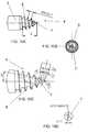
Figures 1A-1C show different views of an external modular fixation system according to the present invention for the temporary or permanent treatment of bone fractures of lower and upper limbs;Figure 2 shows a portion of an external modular fixation system presenting a minor constructional modification in comparison with the system ofFigures 1A-1C ;Figure 3 is a perspective view of an external modular fixation system according to a different embodiment of the present invention;Figure 4 is a perspective view of an external modular fixation system presenting a minor constructional modification with respect to the system ofFigure 3 ;Figure 5 is a view of an elongated pin according to a first embodiment for the external modular fixation system of the present invention;Figures 6A-6C show an enlargement of a conical end portion of the elongated pin ofFigure 5 before the application of the thread;Figures 7A-7D show the thread profile of the threaded conical end portion of the elongated pin ofFigure 5 after the application of the thread;Figure 8 is a view of an elongated pin according to a second embodiment of the external modular fixation system of the present invention;Figures 9A-9C show an enlargement of a conical end portion of the elongated pin ofFigure 8 before the application of the thread;Figures 10A-10D show the thread profile of the threaded conical end portion of the elongated pin ofFigure 8 after the application of the thread.- With reference to
figures 1A-1C , thereference number 1 globally and schematically indicates an external modular fixation system for the treatment of bone fractures and, more specifically, for temporary and/or permanent fixation applications in a method according to the present invention. - The
modular system 1 includes a number of elongated pins orrods 2 having a particular structure. A modular clamp fixation device allows thepins 2 to be connected in a free and modular manner. - The elongated pin presents an
elongated stem 3 extending along a longitudinal axis with anend portion 4 and a tip for insertion into a bone. Thestem 3 is essentially cylindrical in shape although other shapes are possible. - The
end portion 4 with tip has a conical shape with an external thread, forming a conical threaded end portion for insertion into the cortical portion of a bone. - In the following lines we will refer to this pin or
rod 2 with the adjective monocortical to stress the fact that the threadedend portion 4 is inserted only into the cortical portion of the bone without penetrating into the medullary canal. - The profile of the
opposite end 5 of therod 2 is shaped to receive the engagement of a wrench or a spanner or for being inserted in a motor-driven torque-controlled drill. - The threaded
end portion 4 is shown in the enlarged view ofFigure 7A showing an embodiment in which the extension of the threadedconical end portion 4 along the longitudinal axis of the pin is equal to the diameter of the stem; this extension is specifically selected so that the conical end portion penetrates only the cortical portion of the bone. - The rod diameter may be between 3.5 mm and 6.0 mm according to the application. Preferred diameter sizes of the
stem 3 of the pin are 4.0 mm and 5.0 mm, even if this value should not be considered as limiting the rights of the Applicant. - The length of the
monocortical pin 2 may be from 80 mm to 160 mm, depending on the requirements of its particular application. - With reference to the
pin 2 shown infigure 5 , the chosen length can be either 105 mm, 125 mm or 145 mm. - The
stem 3 has a diameter of 5 mm. The length of the threadedconical end portion 4 taken along the longitudinal axis of thepin 2, shown infigure 7A , is equal to 5 mm, which means that the threaded end portion extends along a portion that is equal to the diameter of thestem 3. - A person skilled in the art may appreciate that the diameter combined with the length of the
pin 2 will lend a particularly slender aspect to the pin. - Preferably the
monocortical pin 2 is made of stainless steel with a relatively high elastic modulus that gives a predetermined rigidity to thestem 3 and, at the same time, a good resistance at the threadedend 4. - The threaded
end portion 4 is: - self-drilling
- self-cutting, and
- self-tapping.
- Hereinafter we will disclose a few specific and preferred values of the
thread shape 6 and profile that are given as indicative examples of preferred measurements only, without any intention to limit the Applicant's rights. - The
thread shape 6 has a helical profile and it is obtained at thetip end 4 of the monocortical pin orrod 2. - The
conical end portion 4 has a drill-shaped point 7. - The conical angle of the threaded profile having a conical shape is set at 26°.
- The threaded
conical end portion 4 has an external diameter size of 1.9 mm at the tip. - The drill-
shaped point 7 has a point angle of about 85°-120°, preferably of 90°, as shown inFigure 6B . - The tip of the conical end portion has a size of Ø 0.7 mm.
- The thread pitch is equal to 1 mm.
- The threaded
end portion 4 has a total length of preferably 5.0 mm with an additional length of about 1.0 mm of the undercut, as shown inFigure 7A . Therefore, the length of thethread end portion 4 is commensurate to the diameter ofstem 3. The total number of threads is five. - In the embodiment of
Figures 5-7D , the depth of thread of the helical profile is uniform along the conical end portion. Figures 8-10D show an alternative embodiment of the threadedend portion 4 of the monocortical pin orrod 2.- The embodiment of
Figures 8-10D differs from the embodiment ofFigures 5-7D in that: - the diameter of the rod is equal to 4.0 mm
- the number of threads is equal to four;
- the depth of thread of the helical profile is not uniform along the conical end portion.
- All measurements in many of the
figures 5-10D are given in mm., even where not explicitly indicated. Figures 6A and9A show a base cone of the distal conical end portion of the pin having diameters of 5 mm and 4 mm respectively;figures 6B, 6C and 10B, 10C show the sharpening of the tip without thread of the distal conical end portion of the pin, with diameters of 5 mm and 4 mm respectively;figures 7A-7D and 10A-10D show the finished tip with threaded distal conical end portion of the pin, with diameters of 5 mm and 4 mm respectively.- The pin of
figure 8 is particularly suited for pediatric applications, for instance in treatments for preadolescent children. - For adult applications it would be advisable to use a threaded end portion with a total length of 5 mm; in that case the diameter of the
stem 3 may be 5 mm as well. - In any case, both embodiments of the pin disclosed here and shown in the enclosed figures share certain common features:
- the ratio between the length of the threaded
end portion 4 of therod 2 and the diameter of thestem 3 is 1-1.2, preferably about 1; - the threaded
end portion 4 presents self-drilling, self-cutting and self-tapping features. - The result of this selection provides for single thread profiles that are particularly thin and sharp, offering a large gripping surface during the penetration of the conical end portion into the cortical portion of the bone.
- Testing by the Applicant provided surprising results in terms of high performance in the pull-out force applied to remove the
pin 2 implanted in the cortical portion of a bone. The applied force was over 250 N for tests with low-density sawbones. - Moreover, during other tests performed with sawbones with a density of 50 PCF a pull-out force of about 484 N and a tightening torque of 0,95 Nm were measured, which is comparable to a regular screw implanted in the bone up to the medullary canal.
- The pin of the present invention obtains a series of advantageous results listed below:
- 1) Pin less invasive for the skin;
- 2) Easy insertion without bone breakage;
- 3) Axial load of about 500 [N] (during bone lengthening with a nail in the medullary canal);
- 4) Simple structure means greater ease in bone distraction.
- Now, with specific reference to
Figures 1 to 4 an implementation of thepin 2 in the externalmodular fixation systems - The
external fixation systems pins 2, aproximal group 21 and adistal group 31. - The
proximal group 21 includes at least threepins 2 that have their respective threaded conical ends inserted into the cortical bone portion at predetermined proximal distances from the bone fracture. - Similarly, the
distal group 31 includes at least threepins 2 that have their respective threaded conical ends inserted into the cortical bone portion at predetermined distal distances from the bone fracture. - Two of the three
pins 2 of theproximal group 21 present respective converging longitudinal axes and may be considered to be on the same plane. This plane is parallel to the plane of a proximalclamp plate element 22.Figures 1A-1C show a proximalclamp plate element 22 and a distalclamp plate element 32. However, otherclamp plate elements 62 can be used in a parallel fashion with respect to the proximal anddistal plates figure 2 and as will become clear from the following paragraphs. - Each
pin 2 of theproximal group 21 is supported by and fixed on theclamp plate element 22 at the free ends 5 of the pins that project toward the external part of themodular fixator 1. - The proximal
clamp plate element 22 is substantially a plate with a predetermined thickness, rounded edges and a shape that is slightly curved like a circular segment, as shown clearly inFigure 1C . - The
plate 22 is provided with a number ofholes 23, distributed regularly, to receive correspondingbolt 24 andnut 25 elements that fix thepin 2 to theplate 22. - The
bolt 24 has a through-hole through which thepin 2 passes, which is then blocked in a stable position by tightening thenut 25. - Advantageously, a
third pin 2 of the proximal group is also inserted in the cortical portion of the bone but extending with its longitudinal axis in a third direction that differs from the direction of the other two pins of the group of proximal pins. In this manner the three pins of the proximal group are not coplanar to each other. - More specifically, the
third pin 2 is implanted with its threadedend portion 4 in an area of the cortical bone that is closer to the fracture than the position of the first twopins 2 of theproximal group 21 and fixed by a correspondingbolt 24 andnut 25 in a central position of theclamp plate 22. - This third pin is placed between the two
other pins 2 of theproximal group 21. The other twopins 2 are fixed on the same side of theclamp plate 22 while the third pin in the middle is fixed to the other side of theclamp plate 22; together these three pins form theproximal group 21. - When an additional
clamp plate element 62 is used to form a double clamp plate element, the proximal group is set up to include fourpins 2 instead of three; twopins 2 are blocked on the firstclamp plate element 22 and the other twopins 2 are blocked on the secondclamp plate element 62, as shown for instance inFigure 2 . - When a couple of proximal clamp plate elements is used, the two
proximal clamp elements spacer rods holes 23 at the extremities of both proximalclamp plate elements respective nut 29. - The two pairs of pins fixed on each
clamp plate element - The same configuration with a couple of clamp plate elements can be provided at the distal position so that the
distal group 31 may be arranged in a manner similar to theproximal group 21. - Two
pins 2 of thedistal group 31 have respective converging longitudinal axes and may be considered to be on the same plane. This plane is parallel to the plane of aclamp plate element 32. Thefigures 1A-1C show both the proximalclamp plate element 22 and the distalclamp plate element 32 that are fixed in thefixator system 1 in parallel fashion. - The proximal and
distal groups spacer rods clamp plate elements - These
spacer rods proximal group 21 and the distal group to be adjusted as desired, which would permit thefixator system 1 to be used also for limb lengthening applications, as will be explained later. - Each
pin 2 of thedistal group 31 is supported by and fixed on theclamp plate element 32 in the proximity of the free ends 5 of the pins that project toward the external part of themodular fixator 1. - The distal
clamp plate element 32 is structurally identical to the proximalclamp plate element 22; it is a plate with a predetermined thickness and a shape that is slightly curved like a circular segment. - The distal
clamp plate element 32 is also provided with a number ofholes 33, distributed regularly, to receive correspondingbolt 24 andnut 25 elements to fix thepin 2 to theplate 32. - Each
bolt 24 has a through-hole through which acorresponding pin 2 passes that is then blocked in a stable position by tightening thenut 25. - Advantageously, a
third pin 2 of the distal group is also inserted in the cortical portion of the bone but extending with its longitudinal axis in a third direction that differs from the direction of the other two pins of the group of distal pins. In this manner the three pins of the distal group are not coplanar to each other. - More specifically, the
third pin 2 is implanted with its threadedend portion 4 in an area of the cortical bone that is closer to the fracture than the position of the first twopins 2 of thedistal group 31 and fixed by a correspondingbolt 24 andnut 25 in a central position of theclamp plate 32. - This third pin is placed between the two
other pins 2 of thedistal group 31. The other twopins 2 are fixed on the same side of theclamp plate 32 while the third pin in the middle is fixed to the other side of theclamp plate 22; together these three pins form thedistal group 31. - When an additional
clamp plate element 62 is used to form a double clamp plate element, the distal group is set up to include fourpins 2 instead of three; twopins 2 are blocked on the firstclamp plate element 22 and the other twopins 2 are blocked on the secondclamp plate element 62. - When a couple of distal clamp plate elements is used, the two
distal clamp elements spacer rods holes 23 at the extremities of both distalclamp plate elements respective nut 29. - The two pairs of pins fixed on each
clamp plate element - With reference to the other embodiment of the external
modular fixation system 10 of the present invention, shown inFigure 3 , it represents a customized version of the embodiments shown inFigures 1A-1C and 2 . - In this embodiment the proximal and distal clamp plate elements are identified by the
numerals clamp plate elements - More specifically, these
clamp plate elements portion common fixation rod 65. - Advantageously, each central projecting
portion clamp plate elements proximal group 41 and with a couple of parallel distalclamp plate elements distal group 51 respectively, thus forming a proximal clamp body consisting of a single piece comprising the couple of parallel proximalclamp plate elements portion 55 and a distal clamp body consisting of a single piece comprising the couple of parallel distalclamp plate elements portion 75. - The manner of supporting the
pins 2 with bolt and nut couplings is substantially identical to the embodiment previously disclosed. - Advantageously, the central projecting
portion portion fixation rod 65, as clearly shown in the example ofFigure 3 . - The embodiment of
Figure 3 allows the use of asingle distraction element 35 that is placed parallel to saidfixation rod 65 for the dynamic distraction between the proximal and distal clamp body. Figure 4 shows an external modular fixation system 10' very similar to the embodiment offigure 3 . Here the central projecting portions 55', 75' project for a portion that is greater than the projecting portion of the embodiment illustrated infigure 3 . These much longer projecting portions 55', 75' are slidably mounted on a common rail rod 65'. Thedistraction element 35 is directly fixed to the central projecting portions 55', 75'.- Of the utmost importance in the modular fixation system of the present invention is the fact that the fixing clamp blocks three of the elongated pins in a fixed position with their longitudinal axes not coplanar with each other.
- Thanks to this particular arrangement the group of three pins on different planes forms a hyperstatic structure.
- The modular fixation system of the present invention may be employed in a technique of femoral or tibial lengthening over an intramedullary nail for applications in both children and adults, as disclosed hereafter.
- As a matter of fact the present invention allows for the implementation of a new technique for tibial or femural lengthening simultaneously using or combining the modular
external fixator - The
external fixator - Used in combination with the modular fixation system of the invention, this technique improves alignment and shortens the time with respect to using traditional external fixation devices using pins that penetrate into the medullary canal.
- A nail is inserted into the medullary cavity of the bone while the external fixator of the present invention is fixed only to the cortical portion of the bone.
- The lengthening phase by callotasis is performed with the external fixator system of the present invention.
- In this manner it is possible to control callus formation according to lengthening speed and physiological requirements.
- Once the lengthening phase is completed, the nail is blocked by distal screws while the external fixator is removed during the phase of callus consolidation that normally takes three months.
- Therefore the time in which the external fixator is applied is reduced by more than half when compared with prior art solutions.
- It should be considered that an external fixator is generally not readily accepted, especially by children.
- Possible problems of angular deviations during the lengthening phase with the external fixator mounted, are greatly reduced with the system of the present invention, as the lengthening is guided inside the medullary canal by the presence of the nail.
- Therefore, according to the invention, the basic idea is that of dividing the treatment into different phases while keeping the nail inside the medullary canal in-between the two treatment phases.
- To avoid any contact with screws normally used in traditional external fixation, the invention involves just the
elongated pins 2 that are driven into only the first cortical portion of the bone without penetrating into the medullary canal, which consequently remains free to receive the nail. - Also the diameter of the
pins 2 is important to avoid skin problems. Therefore the reduced dimension of the threadedend portion 4 and thepin stem 3 create fewer complications and greater acceptance of the external fixation system by patients. - The number and positioning of the
pins 2 in a sort of triangular configuration both at the proximal and the distal portions of the fixator is a guarantee of a strong fixation of the whole fixator structure. - In essence the
pins 2 are implanted only in the cortical bone portion and they do not penetrate the medullary canal, thereby avoiding any risk of infection as there is no contact between the nail and the external fixation pins. - Therefore thanks to this invention this technique can even be implemented in tibial lengthening over nails for children, which will overcome all counter-indications and risks of causing growth arrest through serious infection.
- As the limb is lengthened, one end of the bone slides over the nail and the new bone is grown around it.
- The lengthening of the bone may be followed by a corresponding distraction of the modular fixation system.
- After the bone is lengthened, the patient returns to the operating room for the insertion of special screws that lock the nail to the bone. The screws are generally positioned at both ends of the nail on opposite sides of the lengthening zone.
- The external fixation system may then be removed during the same operation.
- Among other advantages, this approach eliminates the risk of pin infection and muscle tethering by the pins, and causes less pain and discomfort.
- This process shortens the total treatment time with an external fixator by more than half. However, tibia or femur lengthening over nails may not be appropriate for all patients, particularly for patients whose problem is linked to an infection, or for young children.
Claims (15)
- Elongated pin (2) for an external modular fixation system for temporary and/or permanent fixation applications to treat bone fractures and to connect two or more bone fragments to each other, comprising an elongated stem (3) extending along a longitudinal axis with a first end portion (4) and an opposite second end portion (5), said first end portion (4) having a tip for the insertion of the first end portion (4) into a bone, said first end portion (4) having a conical shape with an external thread, forming a conical threaded end portion,characterized in that the ratio between the length of the threaded end portion (4) of the rod (2) and the diameter of the stem (3) is 1-1.2.
- Elongated pin according to claim 1, wherein the extension of the conical threaded end portion along the longitudinal axis is substantially equal to the diameter of the stem.
- Elongated pin according to claim 1 or 2, wherein the threaded end portion (4) is self-drilling, self-cutting and self-tapping.
- Elongated pin according to any of the preceding claims, wherein the profile of the second end portion (5) of the elongated pin (2) is shaped for engagement by a spanner or a drill chuck.
- Elongated pin according to any of the preceding claims, wherein the depth of the thread of the helical profile is uniform along the conical end portion.
- Elongated pin according to any of the preceding claims, wherein the extension of the conical end portion is about 3.5 - 6.0 mm.
- External modular fixation system for temporary and/or permanent fixation applications to treat bone fractures and to connect two or more bone fragments to each other, comprising at least three identical elongated pins (2), each pin (2) being made according to any of the preceding claims.
- External modular fixation system according to claim 7 comprising a first fixation clamp element (22) blocking three of said elongated pins in a fixed position, said three pins being blocked in their respective positions with their longitudinal axes coplanar to each other.
- External modular fixation system according to claim 8, comprising a second fixation clamp element (32) blocking three further elongated pins in a fixed position, said three further pins being blocked in their respective positions with their longitudinal axes not coplanar to each other, the first and second fixation clamp (22, 32) being connected to each other by spacer rods (30,40) to form a single rigid structure.
- External modular fixation system according to claim 9, wherein said first and second clamp elements (22,32) comprise respectively first and second plate elements (22, 32, 62 52, 72) of a predetermined thickness and slightly curved like a circular segment.
- External modular fixation system according to claim 10, wherein said clamp plate elements (22, 32, 62, 52, 72) are provided with a number of holes (23, 33), regularly distributed, for receiving corresponding bolt (24) and nut (25) elements to attach the pins (2) to the clamp elements (22, 32).
- External modular fixation system according to claim 11, wherein said first and second clamp plate elements (52, 54; 72,74) comprise a central projecting portion (55, 55') to be connected to a common fixation rod (65; 65').
- External modular fixation system according to claim 12, wherein said central projecting portion (55; 55') is integrally formed with two parallel clamp plate elements (52, 54; 72, 74).
- External modular fixation system according to claim 13, wherein said central projecting portion (55') is slidably mounted on a rail rod (65') that connects said first and second clamp elements.
- External modular fixation system according to claim 14, wherein a distraction element (35) is directly fixed to the central projecting portions (55', 75').
Priority Applications (1)
| Application Number | Priority Date | Filing Date | Title |
|---|---|---|---|
| EP13744426.1AEP2877111B1 (en) | 2012-07-25 | 2013-07-04 | Elongated pin for an external modular fixation system for temporary and/or permanent fixation applications and external modular fixation system |
Applications Claiming Priority (3)
| Application Number | Priority Date | Filing Date | Title |
|---|---|---|---|
| EP12177909 | 2012-07-25 | ||
| EP13744426.1AEP2877111B1 (en) | 2012-07-25 | 2013-07-04 | Elongated pin for an external modular fixation system for temporary and/or permanent fixation applications and external modular fixation system |
| PCT/EP2013/001965WO2014015942A1 (en) | 2012-07-25 | 2013-07-04 | Elongated pin for an external modular fixation system for temporary and/or permanent fixation applications and external modular fixation system |
Publications (2)
| Publication Number | Publication Date |
|---|---|
| EP2877111A1 EP2877111A1 (en) | 2015-06-03 |
| EP2877111B1true EP2877111B1 (en) | 2016-03-02 |
Family
ID=48914200
Family Applications (1)
| Application Number | Title | Priority Date | Filing Date |
|---|---|---|---|
| EP13744426.1AActiveEP2877111B1 (en) | 2012-07-25 | 2013-07-04 | Elongated pin for an external modular fixation system for temporary and/or permanent fixation applications and external modular fixation system |
Country Status (13)
| Country | Link |
|---|---|
| US (1) | US10631896B2 (en) |
| EP (1) | EP2877111B1 (en) |
| JP (1) | JP6495168B2 (en) |
| KR (1) | KR102171796B1 (en) |
| CN (1) | CN104487010B (en) |
| AU (1) | AU2013295399B2 (en) |
| BR (1) | BR112015001589B1 (en) |
| CA (1) | CA2878967C (en) |
| CO (1) | CO7170162A2 (en) |
| ES (1) | ES2573282T3 (en) |
| IL (1) | IL236921A (en) |
| MX (1) | MX375596B (en) |
| WO (1) | WO2014015942A1 (en) |
Families Citing this family (14)
| Publication number | Priority date | Publication date | Assignee | Title |
|---|---|---|---|---|
| WO2014055202A1 (en)* | 2012-09-06 | 2014-04-10 | Solana Surgical LLC | External fixator |
| CN106102616B (en)* | 2014-01-24 | 2018-10-16 | 奥瑟菲克斯有限公司 | Elongate pin for external fixer |
| US10258381B2 (en) | 2014-07-03 | 2019-04-16 | Stryker European Holdings I, Llc | Conical end cap for intramedullary nail |
| EP3045126A1 (en)* | 2015-01-19 | 2016-07-20 | ORTHOFIX S.r.l. | Elongated pin for application of an external fixator |
| JP6206853B2 (en)* | 2015-11-02 | 2017-10-04 | 学校法人静岡理工科大学 | External fixator |
| US10682160B2 (en) | 2015-12-03 | 2020-06-16 | Globus Medical, Inc. | External fixator assembly |
| US9943337B2 (en) | 2015-12-03 | 2018-04-17 | Globus Medical, Inc. | External fixator assembly |
| US9872707B2 (en) | 2015-12-03 | 2018-01-23 | Globus Medical, Inc. | External fixator assembly |
| US10136919B2 (en) | 2015-12-03 | 2018-11-27 | Globus Medical, Inc. | External fixator assembly |
| CN105909660A (en)* | 2016-06-06 | 2016-08-31 | 丽水市伊凡家模具科技有限公司 | Mechanical part |
| US10874433B2 (en) | 2017-01-30 | 2020-12-29 | Stryker European Holdings I, Llc | Strut attachments for external fixation frame |
| CN110613499B (en)* | 2019-10-17 | 2020-10-09 | 中国医学科学院北京协和医院 | Osteotomy guide for body surface lower extremity deformity correction surgery and preparation method thereof |
| US11737786B2 (en) | 2019-12-31 | 2023-08-29 | Orthopediatrics Corp. | Multiple track system for positioning of bone segments |
| US11413070B2 (en) | 2021-11-22 | 2022-08-16 | New Standard Device, LLC | Locking clamp and external fixation horns |
Family Cites Families (63)
| Publication number | Priority date | Publication date | Assignee | Title |
|---|---|---|---|---|
| BE378008A (en)* | 1931-03-07 | |||
| US3915162A (en)* | 1974-02-13 | 1975-10-28 | Peter S Miller | Orthopedic pin identification means |
| CA1077363A (en)* | 1976-08-09 | 1980-05-13 | Richard F. Kronner | Fracture reducing and joint immobilizing apparatus |
| ES253459Y (en)* | 1978-11-10 | 1982-04-16 | EXTERNAL CLINICAL FIXER, OF HIGH STABILITY, TO REDUCE FRACTURES. | |
| US4463753A (en)* | 1980-01-04 | 1984-08-07 | Gustilo Ramon B | Compression bone screw |
| US4548199A (en)* | 1981-11-13 | 1985-10-22 | Agee John M | Fracture splint |
| DE3244819A1 (en)* | 1982-12-03 | 1984-06-07 | Ortopedia Gmbh, 2300 Kiel | DEVICE FOR EXTERNAL FIXING OF BONE FRAGMENTS |
| FR2572929B1 (en)* | 1984-11-15 | 1987-09-04 | Jawish Roger | EXTERNAL FIXER FOR BONES AND JOINTS |
| SE455155B (en)* | 1986-02-12 | 1988-06-27 | Inst For Tillempad Bioteknolog | SCREW SIZE FASTENER FOR PERMANENT ANCHORING IN BONE TAPE |
| IT1237496B (en) | 1989-10-26 | 1993-06-08 | Giuseppe Vrespa | SCREW DEVICE FOR ANCHORING BONE PROSTHESES, METHOD FOR THE APPLICATION OF SUCH DEVICE AND RELATED EQUIPMENT |
| FR2682281B1 (en)* | 1991-10-11 | 1997-01-03 | Sofamor | PERCUTANEOUS SCREW, INTENDED TO SUPPORT IN PARTICULAR A STEREOTAXY FRAMEWORK |
| US5690633A (en)* | 1994-09-23 | 1997-11-25 | Smith & Nephew Richards, Inc. | Orthopedic fracture fixation device |
| US5683389A (en)* | 1994-12-05 | 1997-11-04 | Smith & Nephew, Inc. | External fixator for distal radius fractures |
| US5863292A (en)* | 1996-09-26 | 1999-01-26 | Tosic; Aleksandar | Articulated external orthopedic fixation system and method of use |
| US6159210A (en)* | 1997-01-14 | 2000-12-12 | Research Corporation Technologies, Inc. | Bone fixation pin with rotary cutting tip |
| US5943258A (en)* | 1997-12-24 | 1999-08-24 | Texas Instruments Incorporated | Memory with storage cells having SOI drive and access transistors with tied floating body connections |
| US6019762A (en)* | 1998-04-30 | 2000-02-01 | Orthodyne, Inc. | Adjustable length orthopedic fixation device |
| US6099529A (en)* | 1998-10-26 | 2000-08-08 | Musculoskeletal Transplant Foundation | Allograft bone fixation screw method and apparatus |
| ES2299238T3 (en)* | 1999-04-08 | 2008-05-16 | Orthofix S.R.L. | OSEO SCREW FOR EXTERNAL FIXERS. |
| EP1042989B1 (en)* | 1999-04-08 | 2004-03-03 | Orthofix International B.V. | Improved bone screw for use in orthopedic surgery |
| US6277119B1 (en)* | 1999-10-21 | 2001-08-21 | Electro-Biology, Inc. | External fixation system |
| JP4398129B2 (en)* | 1999-11-15 | 2010-01-13 | アーオー テクノロジー アクチエンゲゼルシャフト | Reduction parameter measuring device for postreduction of broken bones |
| US6423062B2 (en)* | 2000-02-18 | 2002-07-23 | Albert Enayati | Bioabsorbable pin for external bone fixation |
| US6423061B1 (en)* | 2000-03-14 | 2002-07-23 | Amei Technologies Inc. | High tibial osteotomy method and apparatus |
| IL152561A0 (en) | 2000-05-26 | 2003-05-29 | Orthofix Srl | Disposable external fixation device |
| JP3337683B1 (en)* | 2001-04-10 | 2002-10-21 | 吉野 健一 | External fixation device |
| AU783705B2 (en)* | 2001-07-02 | 2005-11-24 | Depuy France | Device for securing bits of bone together |
| US6585736B2 (en)* | 2001-09-19 | 2003-07-01 | Mohammed A. Hajianpour | Device for external fixation of a fractured radius with simultaneous clamping of multiple pins and with a fixture for applying extension to distal bone fragments |
| US9060809B2 (en)* | 2001-10-18 | 2015-06-23 | Orthoip, Llc | Lagwire system and method for the fixation of bone fractures |
| US6716212B1 (en)* | 2002-01-25 | 2004-04-06 | Tyrone Sam Pickens | Universal modular external fixation system |
| DE20202049U1 (en) | 2002-02-11 | 2002-06-13 | Schneider, Willi, Dipl.-Ing., 97616 Bad Neustadt | Device for external fixation of broken bones |
| US6860883B2 (en)* | 2002-02-11 | 2005-03-01 | Pioneer Laboratories, Inc. | External fixation apparatus and method |
| JP3740640B2 (en)* | 2002-04-15 | 2006-02-01 | 廣章 野々宮 | External fixator |
| US7758582B2 (en)* | 2002-06-14 | 2010-07-20 | Smith & Nephew, Inc. | Device and methods for placing external fixation elements |
| US7517350B2 (en)* | 2002-11-20 | 2009-04-14 | Orthopediatrics Corp. | Convertible threaded compression device and method of use |
| US7608074B2 (en)* | 2003-01-10 | 2009-10-27 | Smith & Nephew, Inc. | External fixation apparatus and method |
| US7615051B2 (en)* | 2003-02-21 | 2009-11-10 | Synthes Usa, Llc | Craniofacial fracture reduction assembly |
| CN1265767C (en)* | 2003-04-25 | 2006-07-26 | 常州市第一人民医院 | Restorer for vertebral body and puncture needle for pedicle of vertebral arch by prying operation through skin |
| JP2004350774A (en)* | 2003-05-27 | 2004-12-16 | Oomikku:Kk | External fixation device and piercing pin attaching/detaching joint |
| US7169149B1 (en)* | 2003-07-24 | 2007-01-30 | Phoenix Orthopaedic Corporation | Device for external fixation of a proximal fracture of the ulna with a clamped medullar pin and multiple clamped pins holding bone fragments |
| JP2006101896A (en)* | 2004-09-30 | 2006-04-20 | Keisei Ika Kogyo Kk | External fixer |
| US20070173837A1 (en)* | 2005-11-18 | 2007-07-26 | William Marsh Rice University | Bone fixation and dynamization devices and methods |
| US7731738B2 (en)* | 2005-12-09 | 2010-06-08 | Orthopro, Llc | Cannulated screw |
| SE530328C2 (en)* | 2006-09-21 | 2008-05-06 | Henrik Hansson | Device for fixing a bone fracture |
| EP2120746A2 (en)* | 2007-01-05 | 2009-11-25 | TRANS1, Inc. | Percutaneous delivery of facet screws using depth control indicator |
| US7722611B2 (en)* | 2007-03-05 | 2010-05-25 | Depuy Products, Inc. | Method of treating a clavicle fracture |
| EP1987792B1 (en)* | 2007-05-03 | 2011-06-22 | Medartis AG | Fixing device, combination of a fixing device with a long element, assembly with such a combination and osteosynthesis set |
| US8157828B2 (en)* | 2007-09-24 | 2012-04-17 | MRI Interventions, Inc. | Surgical marking tools and methods for marking a patient |
| US8343189B2 (en)* | 2007-09-25 | 2013-01-01 | Zyga Technology, Inc. | Method and apparatus for facet joint stabilization |
| AU2008318535B2 (en)* | 2007-10-31 | 2014-06-19 | Wright Medical Technology, Inc. | Orthopedic device |
| US8236006B2 (en)* | 2008-01-17 | 2012-08-07 | Life Spine, Inc. | One step entry pedicular preparation device and disc access system |
| WO2009129142A1 (en)* | 2008-04-16 | 2009-10-22 | Synthes Usa, Llc | Apparatus and method for use with fracture table to reposition bone portions |
| US8083740B2 (en)* | 2008-09-28 | 2011-12-27 | Maryam Eslami | Device for facilitating the healing of bone including Olecranan |
| DE502009000626D1 (en)* | 2009-02-16 | 2011-06-16 | Stryker Trauma Ag | Bone screw and manufacturing method for this |
| JP5507113B2 (en)* | 2009-04-24 | 2014-05-28 | 東京応化工業株式会社 | Positive resist composition, resist pattern forming method, polymer compound and compound |
| EP2319436B1 (en) | 2009-11-06 | 2013-02-13 | ORTHOFIX S.r.l. | Clamp for external orthopaedic fixing device |
| US8771325B2 (en)* | 2009-11-20 | 2014-07-08 | T. Hall Griffin | Tapered threaded orthopedic fastener engaging predetermined radial preloads |
| US8409261B2 (en) | 2009-11-20 | 2013-04-02 | T. Hall Griffin | Engaging predetermined radial preloads in securing an orthopedic fastener |
| EP2563250B1 (en)* | 2010-04-27 | 2017-11-15 | Synthes GmbH | Bone fixation system including k-wire compression |
| PT2667808E (en)* | 2011-01-26 | 2015-12-09 | Del Palma Orthopedics Llc | Lower extremity fusion devices |
| CN202235658U (en)* | 2011-09-17 | 2012-05-30 | 王京生 | Elastic intramedullary nail of clavicle |
| US20130172888A1 (en)* | 2011-12-31 | 2013-07-04 | Raul Necuze | External fixator apparatus, especially for the treatment of hand lesions. |
| US8915914B2 (en)* | 2012-07-25 | 2014-12-23 | Orthofix S.R.L. | Method for treating a fracture of a bone having a medullary canal |
- 2013
- 2013-07-04JPJP2015523439Apatent/JP6495168B2/enactiveActive
- 2013-07-04USUS14/417,051patent/US10631896B2/enactiveActive
- 2013-07-04KRKR1020157003726Apatent/KR102171796B1/ennot_activeExpired - Fee Related
- 2013-07-04CACA2878967Apatent/CA2878967C/enactiveActive
- 2013-07-04ESES13744426.1Tpatent/ES2573282T3/enactiveActive
- 2013-07-04AUAU2013295399Apatent/AU2013295399B2/ennot_activeCeased
- 2013-07-04WOPCT/EP2013/001965patent/WO2014015942A1/enactiveApplication Filing
- 2013-07-04MXMX2015001048Apatent/MX375596B/enactiveIP Right Grant
- 2013-07-04CNCN201380039262.2Apatent/CN104487010B/enactiveActive
- 2013-07-04BRBR112015001589-1Apatent/BR112015001589B1/ennot_activeIP Right Cessation
- 2013-07-04EPEP13744426.1Apatent/EP2877111B1/enactiveActive
- 2015
- 2015-01-25ILIL236921Apatent/IL236921A/enactiveIP Right Grant
- 2015-01-26COCO15014655Apatent/CO7170162A2/enunknown
Also Published As
| Publication number | Publication date |
|---|---|
| MX375596B (en) | 2025-03-06 |
| CA2878967A1 (en) | 2014-01-30 |
| JP6495168B2 (en) | 2019-04-03 |
| MX2015001048A (en) | 2015-06-04 |
| IL236921A (en) | 2017-11-30 |
| KR102171796B1 (en) | 2020-10-30 |
| WO2014015942A1 (en) | 2014-01-30 |
| CN104487010B (en) | 2017-05-10 |
| US20150209081A1 (en) | 2015-07-30 |
| AU2013295399A1 (en) | 2015-02-12 |
| US10631896B2 (en) | 2020-04-28 |
| BR112015001589B1 (en) | 2021-02-09 |
| AU2013295399B2 (en) | 2017-05-04 |
| JP2015523163A (en) | 2015-08-13 |
| ES2573282T3 (en) | 2016-06-07 |
| CA2878967C (en) | 2021-02-23 |
| EP2877111A1 (en) | 2015-06-03 |
| CN104487010A (en) | 2015-04-01 |
| KR20150034256A (en) | 2015-04-02 |
| HK1204905A1 (en) | 2015-12-11 |
| BR112015001589A2 (en) | 2018-03-20 |
| CO7170162A2 (en) | 2015-01-28 |
Similar Documents
| Publication | Publication Date | Title |
|---|---|---|
| EP2877111B1 (en) | Elongated pin for an external modular fixation system for temporary and/or permanent fixation applications and external modular fixation system | |
| US8915914B2 (en) | Method for treating a fracture of a bone having a medullary canal | |
| US11602383B2 (en) | Devices for generating and applying compression within a body | |
| EP1809190B1 (en) | Endosteal nail | |
| EP2389884B1 (en) | Implant for bone fixation | |
| Moss et al. | Biomechanics of external fixation | |
| US20070173834A1 (en) | Flexible Nail Assembly For Fractures Of Long Bones | |
| EP3229713B1 (en) | Wire tensioner tip and wire fixation bolt | |
| ES2400600T3 (en) | Device for stabilizing long bone fractures | |
| HK1204905B (en) | Elongated pin for an external modular fixation system for temporary and/or permanent fixation applications and external modular fixation system | |
| RU146659U1 (en) | INTRAMEDOLLARY DEVICE FOR OSTEOSYNTHESIS OF UPPER THREE FEMORAL FRACTURES | |
| JP2017503618A (en) | Elongated pins for external fixator applications |
Legal Events
| Date | Code | Title | Description |
|---|---|---|---|
| PUAI | Public reference made under article 153(3) epc to a published international application that has entered the european phase | Free format text:ORIGINAL CODE: 0009012 | |
| 17P | Request for examination filed | Effective date:20150219 | |
| AK | Designated contracting states | Kind code of ref document:A1 Designated state(s):AL AT BE BG CH CY CZ DE DK EE ES FI FR GB GR HR HU IE IS IT LI LT LU LV MC MK MT NL NO PL PT RO RS SE SI SK SM TR | |
| AX | Request for extension of the european patent | Extension state:BA ME | |
| GRAP | Despatch of communication of intention to grant a patent | Free format text:ORIGINAL CODE: EPIDOSNIGR1 | |
| DAX | Request for extension of the european patent (deleted) | ||
| INTG | Intention to grant announced | Effective date:20151015 | |
| RAP1 | Party data changed (applicant data changed or rights of an application transferred) | Owner name:ORTHOFIX S.R.L. | |
| RIN1 | Information on inventor provided before grant (corrected) | Inventor name:VENTURINI, DANIELE | |
| REG | Reference to a national code | Ref country code:HK Ref legal event code:DE Ref document number:1204905 Country of ref document:HK | |
| GRAS | Grant fee paid | Free format text:ORIGINAL CODE: EPIDOSNIGR3 | |
| GRAA | (expected) grant | Free format text:ORIGINAL CODE: 0009210 | |
| AK | Designated contracting states | Kind code of ref document:B1 Designated state(s):AL AT BE BG CH CY CZ DE DK EE ES FI FR GB GR HR HU IE IS IT LI LT LU LV MC MK MT NL NO PL PT RO RS SE SI SK SM TR | |
| REG | Reference to a national code | Ref country code:GB Ref legal event code:FG4D | |
| REG | Reference to a national code | Ref country code:AT Ref legal event code:REF Ref document number:777429 Country of ref document:AT Kind code of ref document:T Effective date:20160315 Ref country code:CH Ref legal event code:EP | |
| REG | Reference to a national code | Ref country code:IE Ref legal event code:FG4D | |
| REG | Reference to a national code | Ref country code:DE Ref legal event code:R096 Ref document number:602013005284 Country of ref document:DE | |
| REG | Reference to a national code | Ref country code:CH Ref legal event code:NV Representative=s name:ING. MARCO ZARDI C/O M. ZARDI AND CO. S.A., CH | |
| REG | Reference to a national code | Ref country code:ES Ref legal event code:FG2A Ref document number:2573282 Country of ref document:ES Kind code of ref document:T3 Effective date:20160607 | |
| REG | Reference to a national code | Ref country code:FR Ref legal event code:PLFP Year of fee payment:4 | |
| REG | Reference to a national code | Ref country code:NL Ref legal event code:MP Effective date:20160302 | |
| REG | Reference to a national code | Ref country code:LT Ref legal event code:MG4D | |
| REG | Reference to a national code | Ref country code:AT Ref legal event code:MK05 Ref document number:777429 Country of ref document:AT Kind code of ref document:T Effective date:20160302 | |
| PG25 | Lapsed in a contracting state [announced via postgrant information from national office to epo] | Ref country code:FI Free format text:LAPSE BECAUSE OF FAILURE TO SUBMIT A TRANSLATION OF THE DESCRIPTION OR TO PAY THE FEE WITHIN THE PRESCRIBED TIME-LIMIT Effective date:20160302 Ref country code:NO Free format text:LAPSE BECAUSE OF FAILURE TO SUBMIT A TRANSLATION OF THE DESCRIPTION OR TO PAY THE FEE WITHIN THE PRESCRIBED TIME-LIMIT Effective date:20160602 Ref country code:GR Free format text:LAPSE BECAUSE OF FAILURE TO SUBMIT A TRANSLATION OF THE DESCRIPTION OR TO PAY THE FEE WITHIN THE PRESCRIBED TIME-LIMIT Effective date:20160603 Ref country code:HR Free format text:LAPSE BECAUSE OF FAILURE TO SUBMIT A TRANSLATION OF THE DESCRIPTION OR TO PAY THE FEE WITHIN THE PRESCRIBED TIME-LIMIT Effective date:20160302 | |
| PG25 | Lapsed in a contracting state [announced via postgrant information from national office to epo] | Ref country code:AT Free format text:LAPSE BECAUSE OF FAILURE TO SUBMIT A TRANSLATION OF THE DESCRIPTION OR TO PAY THE FEE WITHIN THE PRESCRIBED TIME-LIMIT Effective date:20160302 Ref country code:SE Free format text:LAPSE BECAUSE OF FAILURE TO SUBMIT A TRANSLATION OF THE DESCRIPTION OR TO PAY THE FEE WITHIN THE PRESCRIBED TIME-LIMIT Effective date:20160302 Ref country code:NL Free format text:LAPSE BECAUSE OF FAILURE TO SUBMIT A TRANSLATION OF THE DESCRIPTION OR TO PAY THE FEE WITHIN THE PRESCRIBED TIME-LIMIT Effective date:20160302 Ref country code:LT Free format text:LAPSE BECAUSE OF FAILURE TO SUBMIT A TRANSLATION OF THE DESCRIPTION OR TO PAY THE FEE WITHIN THE PRESCRIBED TIME-LIMIT Effective date:20160302 Ref country code:RS Free format text:LAPSE BECAUSE OF FAILURE TO SUBMIT A TRANSLATION OF THE DESCRIPTION OR TO PAY THE FEE WITHIN THE PRESCRIBED TIME-LIMIT Effective date:20160302 Ref country code:PL Free format text:LAPSE BECAUSE OF FAILURE TO SUBMIT A TRANSLATION OF THE DESCRIPTION OR TO PAY THE FEE WITHIN THE PRESCRIBED TIME-LIMIT Effective date:20160302 Ref country code:LV Free format text:LAPSE BECAUSE OF FAILURE TO SUBMIT A TRANSLATION OF THE DESCRIPTION OR TO PAY THE FEE WITHIN THE PRESCRIBED TIME-LIMIT Effective date:20160302 | |
| REG | Reference to a national code | Ref country code:HK Ref legal event code:GR Ref document number:1204905 Country of ref document:HK | |
| PG25 | Lapsed in a contracting state [announced via postgrant information from national office to epo] | Ref country code:EE Free format text:LAPSE BECAUSE OF FAILURE TO SUBMIT A TRANSLATION OF THE DESCRIPTION OR TO PAY THE FEE WITHIN THE PRESCRIBED TIME-LIMIT Effective date:20160302 Ref country code:IS Free format text:LAPSE BECAUSE OF FAILURE TO SUBMIT A TRANSLATION OF THE DESCRIPTION OR TO PAY THE FEE WITHIN THE PRESCRIBED TIME-LIMIT Effective date:20160702 | |
| PG25 | Lapsed in a contracting state [announced via postgrant information from national office to epo] | Ref country code:RO Free format text:LAPSE BECAUSE OF FAILURE TO SUBMIT A TRANSLATION OF THE DESCRIPTION OR TO PAY THE FEE WITHIN THE PRESCRIBED TIME-LIMIT Effective date:20160302 Ref country code:SM Free format text:LAPSE BECAUSE OF FAILURE TO SUBMIT A TRANSLATION OF THE DESCRIPTION OR TO PAY THE FEE WITHIN THE PRESCRIBED TIME-LIMIT Effective date:20160302 Ref country code:PT Free format text:LAPSE BECAUSE OF FAILURE TO SUBMIT A TRANSLATION OF THE DESCRIPTION OR TO PAY THE FEE WITHIN THE PRESCRIBED TIME-LIMIT Effective date:20160704 Ref country code:SK Free format text:LAPSE BECAUSE OF FAILURE TO SUBMIT A TRANSLATION OF THE DESCRIPTION OR TO PAY THE FEE WITHIN THE PRESCRIBED TIME-LIMIT Effective date:20160302 Ref country code:CZ Free format text:LAPSE BECAUSE OF FAILURE TO SUBMIT A TRANSLATION OF THE DESCRIPTION OR TO PAY THE FEE WITHIN THE PRESCRIBED TIME-LIMIT Effective date:20160302 | |
| REG | Reference to a national code | Ref country code:DE Ref legal event code:R097 Ref document number:602013005284 Country of ref document:DE | |
| PG25 | Lapsed in a contracting state [announced via postgrant information from national office to epo] | Ref country code:BE Free format text:LAPSE BECAUSE OF FAILURE TO SUBMIT A TRANSLATION OF THE DESCRIPTION OR TO PAY THE FEE WITHIN THE PRESCRIBED TIME-LIMIT Effective date:20160302 | |
| PLBE | No opposition filed within time limit | Free format text:ORIGINAL CODE: 0009261 | |
| STAA | Information on the status of an ep patent application or granted ep patent | Free format text:STATUS: NO OPPOSITION FILED WITHIN TIME LIMIT | |
| PG25 | Lapsed in a contracting state [announced via postgrant information from national office to epo] | Ref country code:DK Free format text:LAPSE BECAUSE OF FAILURE TO SUBMIT A TRANSLATION OF THE DESCRIPTION OR TO PAY THE FEE WITHIN THE PRESCRIBED TIME-LIMIT Effective date:20160302 | |
| 26N | No opposition filed | Effective date:20161205 | |
| PG25 | Lapsed in a contracting state [announced via postgrant information from national office to epo] | Ref country code:SI Free format text:LAPSE BECAUSE OF FAILURE TO SUBMIT A TRANSLATION OF THE DESCRIPTION OR TO PAY THE FEE WITHIN THE PRESCRIBED TIME-LIMIT Effective date:20160302 Ref country code:BG Free format text:LAPSE BECAUSE OF FAILURE TO SUBMIT A TRANSLATION OF THE DESCRIPTION OR TO PAY THE FEE WITHIN THE PRESCRIBED TIME-LIMIT Effective date:20160602 | |
| PG25 | Lapsed in a contracting state [announced via postgrant information from national office to epo] | Ref country code:MC Free format text:LAPSE BECAUSE OF FAILURE TO SUBMIT A TRANSLATION OF THE DESCRIPTION OR TO PAY THE FEE WITHIN THE PRESCRIBED TIME-LIMIT Effective date:20160302 | |
| REG | Reference to a national code | Ref country code:IE Ref legal event code:MM4A | |
| REG | Reference to a national code | Ref country code:FR Ref legal event code:PLFP Year of fee payment:5 | |
| PG25 | Lapsed in a contracting state [announced via postgrant information from national office to epo] | Ref country code:IE Free format text:LAPSE BECAUSE OF NON-PAYMENT OF DUE FEES Effective date:20160704 | |
| PG25 | Lapsed in a contracting state [announced via postgrant information from national office to epo] | Ref country code:LU Free format text:LAPSE BECAUSE OF NON-PAYMENT OF DUE FEES Effective date:20160704 | |
| PG25 | Lapsed in a contracting state [announced via postgrant information from national office to epo] | Ref country code:HU Free format text:LAPSE BECAUSE OF FAILURE TO SUBMIT A TRANSLATION OF THE DESCRIPTION OR TO PAY THE FEE WITHIN THE PRESCRIBED TIME-LIMIT; INVALID AB INITIO Effective date:20130704 | |
| REG | Reference to a national code | Ref country code:FR Ref legal event code:PLFP Year of fee payment:6 | |
| PG25 | Lapsed in a contracting state [announced via postgrant information from national office to epo] | Ref country code:MT Free format text:LAPSE BECAUSE OF NON-PAYMENT OF DUE FEES Effective date:20160731 Ref country code:MK Free format text:LAPSE BECAUSE OF FAILURE TO SUBMIT A TRANSLATION OF THE DESCRIPTION OR TO PAY THE FEE WITHIN THE PRESCRIBED TIME-LIMIT Effective date:20160302 Ref country code:CY Free format text:LAPSE BECAUSE OF FAILURE TO SUBMIT A TRANSLATION OF THE DESCRIPTION OR TO PAY THE FEE WITHIN THE PRESCRIBED TIME-LIMIT Effective date:20160302 | |
| PG25 | Lapsed in a contracting state [announced via postgrant information from national office to epo] | Ref country code:TR Free format text:LAPSE BECAUSE OF FAILURE TO SUBMIT A TRANSLATION OF THE DESCRIPTION OR TO PAY THE FEE WITHIN THE PRESCRIBED TIME-LIMIT Effective date:20160302 Ref country code:AL Free format text:LAPSE BECAUSE OF FAILURE TO SUBMIT A TRANSLATION OF THE DESCRIPTION OR TO PAY THE FEE WITHIN THE PRESCRIBED TIME-LIMIT Effective date:20160302 | |
| PGFP | Annual fee paid to national office [announced via postgrant information from national office to epo] | Ref country code:ES Payment date:20220801 Year of fee payment:10 Ref country code:DE Payment date:20220621 Year of fee payment:10 | |
| PGFP | Annual fee paid to national office [announced via postgrant information from national office to epo] | Ref country code:CH Payment date:20220801 Year of fee payment:10 | |
| P01 | Opt-out of the competence of the unified patent court (upc) registered | Effective date:20230527 | |
| PGFP | Annual fee paid to national office [announced via postgrant information from national office to epo] | Ref country code:FR Payment date:20230621 Year of fee payment:11 | |
| PGFP | Annual fee paid to national office [announced via postgrant information from national office to epo] | Ref country code:GB Payment date:20230620 Year of fee payment:11 | |
| REG | Reference to a national code | Ref country code:DE Ref legal event code:R119 Ref document number:602013005284 Country of ref document:DE | |
| REG | Reference to a national code | Ref country code:CH Ref legal event code:PL | |
| PG25 | Lapsed in a contracting state [announced via postgrant information from national office to epo] | Ref country code:DE Free format text:LAPSE BECAUSE OF NON-PAYMENT OF DUE FEES Effective date:20240201 Ref country code:CH Free format text:LAPSE BECAUSE OF NON-PAYMENT OF DUE FEES Effective date:20230731 | |
| REG | Reference to a national code | Ref country code:ES Ref legal event code:FD2A Effective date:20240827 | |
| PGFP | Annual fee paid to national office [announced via postgrant information from national office to epo] | Ref country code:IT Payment date:20240619 Year of fee payment:12 | |
| PG25 | Lapsed in a contracting state [announced via postgrant information from national office to epo] | Ref country code:ES Free format text:LAPSE BECAUSE OF NON-PAYMENT OF DUE FEES Effective date:20230705 | |
| PG25 | Lapsed in a contracting state [announced via postgrant information from national office to epo] | Ref country code:ES Free format text:LAPSE BECAUSE OF NON-PAYMENT OF DUE FEES Effective date:20230705 | |
| GBPC | Gb: european patent ceased through non-payment of renewal fee | Effective date:20240704 | |
| PG25 | Lapsed in a contracting state [announced via postgrant information from national office to epo] | Ref country code:FR Free format text:LAPSE BECAUSE OF NON-PAYMENT OF DUE FEES Effective date:20240731 | |
| PG25 | Lapsed in a contracting state [announced via postgrant information from national office to epo] | Ref country code:GB Free format text:LAPSE BECAUSE OF NON-PAYMENT OF DUE FEES Effective date:20240704 |