EP2877100B1 - Shaft for medical instruments, comprising movable sections - Google Patents
Shaft for medical instruments, comprising movable sectionsDownload PDFInfo
- Publication number
- EP2877100B1 EP2877100B1EP13744480.8AEP13744480AEP2877100B1EP 2877100 B1EP2877100 B1EP 2877100B1EP 13744480 AEP13744480 AEP 13744480AEP 2877100 B1EP2877100 B1EP 2877100B1
- Authority
- EP
- European Patent Office
- Prior art keywords
- another
- shank
- shaft
- sections
- toothings
- Prior art date
- Legal status (The legal status is an assumption and is not a legal conclusion. Google has not performed a legal analysis and makes no representation as to the accuracy of the status listed.)
- Active
Links
- 230000006835compressionEffects0.000claimsdescription5
- 238000007906compressionMethods0.000claimsdescription5
- 238000005096rolling processMethods0.000description9
- 238000005452bendingMethods0.000description3
- 230000001681protective effectEffects0.000description3
- 238000004904shorteningMethods0.000description3
- 230000000694effectsEffects0.000description2
- 230000007704transitionEffects0.000description2
- 229920002595Dielectric elastomerPolymers0.000description1
- 238000004026adhesive bondingMethods0.000description1
- WYTGDNHDOZPMIW-RCBQFDQVSA-NalstonineNatural productsC1=CC2=C3C=CC=CC3=NC2=C2N1C[C@H]1[C@H](C)OC=C(C(=O)OC)[C@H]1C2WYTGDNHDOZPMIW-RCBQFDQVSA-N0.000description1
- 230000000712assemblyEffects0.000description1
- 238000000429assemblyMethods0.000description1
- 230000005540biological transmissionEffects0.000description1
- 230000000903blocking effectEffects0.000description1
- 210000000080chela (arthropods)Anatomy0.000description1
- 239000004020conductorSubstances0.000description1
- 238000006073displacement reactionMethods0.000description1
- 229920001746electroactive polymerPolymers0.000description1
- 239000000835fiberSubstances0.000description1
- 238000007373indentationMethods0.000description1
- 239000007788liquidSubstances0.000description1
- 238000002324minimally invasive surgeryMethods0.000description1
- 230000003287optical effectEffects0.000description1
- 238000001356surgical procedureMethods0.000description1
- 238000003466weldingMethods0.000description1
Images


Classifications
- A—HUMAN NECESSITIES
- A61—MEDICAL OR VETERINARY SCIENCE; HYGIENE
- A61B—DIAGNOSIS; SURGERY; IDENTIFICATION
- A61B34/00—Computer-aided surgery; Manipulators or robots specially adapted for use in surgery
- A61B34/70—Manipulators specially adapted for use in surgery
- A—HUMAN NECESSITIES
- A61—MEDICAL OR VETERINARY SCIENCE; HYGIENE
- A61B—DIAGNOSIS; SURGERY; IDENTIFICATION
- A61B17/00—Surgical instruments, devices or methods
- A61B17/00234—Surgical instruments, devices or methods for minimally invasive surgery
- A—HUMAN NECESSITIES
- A61—MEDICAL OR VETERINARY SCIENCE; HYGIENE
- A61B—DIAGNOSIS; SURGERY; IDENTIFICATION
- A61B34/00—Computer-aided surgery; Manipulators or robots specially adapted for use in surgery
- A61B34/30—Surgical robots
- A—HUMAN NECESSITIES
- A61—MEDICAL OR VETERINARY SCIENCE; HYGIENE
- A61B—DIAGNOSIS; SURGERY; IDENTIFICATION
- A61B34/00—Computer-aided surgery; Manipulators or robots specially adapted for use in surgery
- A61B34/70—Manipulators specially adapted for use in surgery
- A61B34/71—Manipulators operated by drive cable mechanisms
- A—HUMAN NECESSITIES
- A61—MEDICAL OR VETERINARY SCIENCE; HYGIENE
- A61B—DIAGNOSIS; SURGERY; IDENTIFICATION
- A61B17/00—Surgical instruments, devices or methods
- A61B17/00234—Surgical instruments, devices or methods for minimally invasive surgery
- A61B2017/00292—Surgical instruments, devices or methods for minimally invasive surgery mounted on or guided by flexible, e.g. catheter-like, means
- A61B2017/003—Steerable
- A61B2017/00305—Constructional details of the flexible means
- A61B2017/00314—Separate linked members
- A—HUMAN NECESSITIES
- A61—MEDICAL OR VETERINARY SCIENCE; HYGIENE
- A61B—DIAGNOSIS; SURGERY; IDENTIFICATION
- A61B17/00—Surgical instruments, devices or methods
- A61B17/00234—Surgical instruments, devices or methods for minimally invasive surgery
- A61B2017/00292—Surgical instruments, devices or methods for minimally invasive surgery mounted on or guided by flexible, e.g. catheter-like, means
- A61B2017/003—Steerable
- A61B2017/00318—Steering mechanisms
- A61B2017/00323—Cables or rods
- A—HUMAN NECESSITIES
- A61—MEDICAL OR VETERINARY SCIENCE; HYGIENE
- A61B—DIAGNOSIS; SURGERY; IDENTIFICATION
- A61B34/00—Computer-aided surgery; Manipulators or robots specially adapted for use in surgery
- A61B34/30—Surgical robots
- A61B2034/305—Details of wrist mechanisms at distal ends of robotic arms
- A61B2034/306—Wrists with multiple vertebrae
Definitions
- the inventionrelates to a medical instrument with the features specified in the preamble of claim 1.
- Medical instrumentsin particular endoscopic instruments, are known which have a shaft which is designed to be angled in at least one area.
- Shaftsare known which have individual swivel joints or movable shafts which have a large number of shaft sections which can be moved relative to one another.
- the EP 0 612 496 A1describes a shaft for medical instruments, which is composed of a plurality of shaft sections strung together.
- the shaft sectionsmesh with one another via arcuate teeth.
- the teethare designed in such a way that the teeth of a first shaft section are always convex and in a engages concave teeth on an opposite shaft portion. Such an arrangement allows only little flexibility.
- the WO 2009/145572 A2describes an instrument for minimally invasive surgery which has a joint that can be pivoted in two directions at its distal end and at its proximal end.
- the jointsare formed from movable sections which have meshing gear sections, the articulated sections being connected to one another via rigid connecting webs which can each be rotated about hinge axes which extend concentrically to the gear sections. This structure is complex to assemble.
- KR 2010-0131338 AA similar structure is out KR 2010-0131338 A known.
- the joint elements that roll over one anotherare connected to one another by wrapping bands.
- the medical instrument according to the inventionhas, in a known manner, at least one preferably hollow shaft which has at least two adjacent shaft sections which can be moved relative to one another.
- the two shaft sectionscan pivot relative to one another.
- the at least two movable shaft sectionsare designed in such a way that they either mesh with one another in a form-fitting manner via teeth or are in frictional engagement with one another, so that they roll off one another without slipping.
- the two movable shaft sectionsroll off one another in the manner of a gear drive or with a friction fit, slip-free and are always in a defined form-fitting or force-fitting engagement with one another.
- the two shaft sectionsalways perform a defined movement relative to one another, predetermined by the toothing or the frictional engagement, if they are caused to deflect, for example by tension elements.
- the shafthas a plurality of mutually movable shaft sections, of which two mutually adjacent shaft sections are in meshing engagement with each other via teeth or frictionally rolling against each other.
- the shafthas a plurality of mutually movable shaft sections, of which two mutually adjacent shaft sections are in meshing engagement with each other via teeth or frictionally rolling against each other.
- the teethare designed in such a way that two adjacent shaft sections are provided with corresponding teeth on their opposite end faces, which are in engagement with one another so that the two shaft sections can pivot relative to one another. This pivoting movement can in particular take place by the shaft sections rolling over one another or in the toothings which are in engagement with one another.
- the shaft sectionseach have friction or engagement surfaces which abut against one another in a frictionally engaged manner, ie. H. on two adjacent shaft sections, mutually corresponding contact surfaces or friction surfaces are formed at their opposite end faces, which frictionally engage with each other so that the two shaft sections can pivot relative to each other.
- the friction surfacesroll off one another without slipping.
- the mutually corresponding and abutting friction surfacescan have roughened or elastic surface structures which ensure frictional engagement and non-slip rolling.
- At least individual toothings or friction surfacesare arcuate. I.e. at least one of the two toothings or friction surfaces which are in engagement with one another is arcuate. Both teeth meshing with one another or friction surfaces in engagement are preferably designed in an arc shape so that a rolling movement takes place on one another.
- the intermeshing teeth or friction surfaces that roll against one anotherhave the same radius of curvature at the opposite end faces of two adjacent shaft sections. In this way, an even angle is achieved.
- the intermeshing teeth or the friction surfaces rolling against one anotherare curved in opposite directions on the opposite end faces of two adjacent shaft sections.
- the arc shapepreferably corresponds to a circular arc shape.
- the adjacent shaft sectionshave a toothing or friction surface on their facing ends on two diametrically opposite sides.
- the teeth or friction surfacesthus preferably extend in at least two planes parallel to one another and to the longitudinal axis of the shaft section, which form the pivot planes in which the two parallel shaft sections can pivot to one another.
- the toothings or friction surfacespreferably extend in planes which are arranged tangentially or in the form of a chord to the outer wall of the shaft section.
- the teeth or friction surfacesthus preferably extend arcuately around the same axis on the two diametrically opposite sides. As described, they have a Circular arc shape.
- identically designed toothing or friction surfacesare correspondingly preferably located on the opposite side of an adjacent shaft section.
- the shafthas at least three shaft sections which can move relative to one another, of which the respectively adjacent shaft sections are in meshing engagement with one another via teeth or rolling against one another in a frictional manner.
- the toothings or friction surfacescan be designed in the manner described above.
- the first and the second shaft sectionare further preferably movable relative to one another in a first pivot plane and the second and the third shaft section in a second pivot plane. I.e. the swivel planes between the individual shaft sections alternate so that mobility in different directions is achieved.
- the first and second pivot planespreferably extend perpendicular to one another, so that the individual pivot planes alternate with one another offset by 90 ° with respect to the longitudinal axis of the shaft.
- the shaftto be deflected in all spatial directions by combining or superimposing the pivoting movements in the two directions.
- the planes of extension in which the arcuate toothings or friction surfaces are locatedare arranged offset from one another by 90 ° from one interface to the next. I.e. Between the first and the second shaft section, the curved teeth or friction surfaces are arranged in planes parallel to the first pivot plane, while the curved teeth or friction surfaces between the second and third shaft sections are arranged parallel to the second pivot plane. If there are more than three shaft sections, this continues accordingly.
- the teeth or friction surfacesare arcuate and the teeth or friction surfaces between the first and the second section are preferably about axes, ie. H. particularly preferably curved around the same axis, which extend normal to the axes or the axis around which the teeth or friction surfaces are curved between the second and the third shaft section. These axes, around which the toothings or friction surfaces are curved, extend normal to the respective pivot planes in which the pivot movements between the two adjacent shaft sections are carried out.
- the at least two movable shaft sectionsare in meshing engagement with one another via toothings and simultaneously roll off one another via curved contact surfaces. That is to say, at least one arcuate toothing and at least one arcuate contact surface are formed on the sides facing one another on the two shaft sections. The teeth mesh with one another and the arcuate contact surfaces which face one another rest against one another.
- This embodimenthas the advantage that the toothings are kept at a defined distance from one another during pivoting via the arcuate contact surfaces, that is, a constant axial distance is maintained between the pivot axes of the two shaft sections. This is defined by the curved contact surfaces.
- a lateral guideis preferably provided at the same time, which prevents a displacement of adjoining shaft sections in the direction of the pivot axis.
- a lateral guidecan be formed by a wall or flank adjoining the curved contact surface, that is to say extending transversely to the contact surface.
- the heads of the teethcan protrude in the radial direction over an adjoining contact surface, so that side flanks are created between the teeth, against which the protruding teeth of an opposite shaft section abut during lateral movement so that this is limited or prevented.
- each shaft sectionhas at least one arcuate contact surface and a toothing, the arcuate contact surface expediently being curved parallel to the toothing. This ensures that the axial distance between the shaft sections is kept constant in every angular position when pivoting.
- the arcuate contact surfaceparticularly preferably has the same radius or radius of curvature as the pitch circle of the toothing.
- clamping elementswhich extend in the axial direction of the shaft. These are tension ropes which are pretensioned by spring elements in such a way that the shaft sections are always held in contact even during pivoting movements, so that the teeth remain in meshing engagement or friction surfaces are held in contact with frictional engagement so that rolling takes place without slippage can.
- the shaft sectionscan also be held in abutment via the tension elements described below.
- the individual shaft sectionsare deflected using pull wires or pull cables.
- pull wires or pull cablesFor this purpose, at least two puller wires extending in the longitudinal direction of the shaft are provided, which are attached with their distal end to two diametrically opposite sides of a distal shaft section. These two diametrically opposite sides, on which the puller wires are attached and located, are preferably located in the pivot plane within which the respective shaft sections are intended to pivot relative to one another.
- At least four puller wireswhich are each attached to a distal shaft section offset by 90 ° with respect to the longitudinal axis.
- Two of the pull wiresare located diametrically opposite, preferably in the first described swivel plane, and the two other pull wires are located diametrically opposite in a swivel plane offset by 90 ° about the longitudinal axis of the shaft. I.e. two of the pull wires are responsible for the swivel movement in the first swivel plane and two of the pull wires are responsible for the swivel movement in the second swivel plane.
- the puller wiresare provided which are connected to one another at their distal ends.
- the connection of the pull wiresfacilitates assembly.
- all pull wires or control cablesare in a distal shaft section, i. H. connected to the last movable shaft section at the distal end.
- the puller wirescan simply be threaded through the guides and recesses provided in the shaft sections adjoining the proximal end to the proximal end.
- the four puller wirescan preferably be designed as two U-shaped loops which intersect and are connected to one another at their intersection or center point. This connection can be made, for example, by welding or gluing or clamping.
- puller wiresare not hinged to the distal shaft section, but rather to shaft sections located further proximally, then it is also possible to move individual shaft sections against one another in a defined manner via corresponding pairs of puller wires. I.e. For each joint or each movable shaft section, a pair of pull wires is provided which is fastened in the pivot plane of this shaft section on diametrically opposite sides of the shaft section. In this way, a defined, serpentine deflection of the instrument can be achieved.
- guides for these puller wiresare furthermore preferably formed. This ensures that the pull wires are guided in a defined manner in the shaft wall or on the shaft wall.
- the guidesoffer contact points which enable deflection in a defined manner by pulling on the tension wires. This creates force application points for the puller wires.
- the at least two adjacent shaft sections that are movable relative to one anotherhave a lateral guide.
- the two shaft sectionsare in engagement with one another via a lateral guide extending parallel to the pivot plane.
- the lateral guidecan be formed by one or more guide surfaces.
- At least one webpreferably protrudes from one of the shaft sections and engages in an opposite groove. The web and the groove extend in the pivot plane or parallel to the pivot plane.
- only one lateral guide in the form of a webis provided, which is preferably located in the central area.
- two lateral guideswhich are spaced apart from one another in the diameter direction and extend parallel to one another can also be provided.
- the shaft of the medical instrumentis hollow.
- the at least two movable shaft sectionscan each have a central cavity extending through the shaft section in the axial direction, the cavities of the plurality of shaft sections being aligned with one another. In this way, through the movable shaft sections, a continuous, in created cavity extending in the axial direction.
- This cavity or channelallows the guidance and optional attachment of further assemblies, such as optical waveguides, image conductors, electrical cables, hoses or pipes for guiding media such as gas or liquids, hoses or pipes for guiding application tools such as pliers, baskets, laser fibers, Force transmission elements such as rods, trains, micro drives such as piezo drives, actuators based on shape memory, electroactive polymer actuators, dielectric elastomer actuators, magnetostrictive drives, magnetorheological drives, pneumatic and hydraulic drives, as well as electromagnetic drives, etc.
- further assembliessuch as optical waveguides, image conductors, electrical cables, hoses or pipes for guiding media such as gas or liquids, hoses or pipes for guiding application tools such as pliers, baskets, laser fibers, Force transmission elements such as rods, trains, micro drives such as piezo drives, actuators based on shape memory, electroactive polymer actuators, dielectric elastomer actuators, magnetostrictive drives, magnetorheological drives, pneumatic
- the medical instrument according to the inventionis preferably an endoscopic instrument and, in a known manner, has a shaft 2, the distal shaft region 4 of which can be angled.
- a forceps mouth 6is arranged at the distal end of the shaft.
- the forceps jaw 6can be moved in a known manner from the proximal end of the shaft 2 (the proximal end is not shown here) via a handle or electrical drives.
- actuating elementssuch as tension or pressure elements, can run in the axial direction X inside the shaft.
- the distal shaft region 4consists of a plurality of shaft sections 8 arranged axially adjacent to one another.
- the shaft sections 8are on their outer circumference, as in Fig. 1 shown schematically, surrounded by a protective tube.
- the shaft sections 8are held against one another in the axial direction by means of two diametrically spaced tension cables 12.
- the tension cables 12extend, as in FIG Fig. 2 and 3 shown, by guide grooves 14 in the walls of the shaft sections 8.
- the tensioning cables 12are fixed on the distal shaft section 8a, which is located closest to the forceps mouth 6.
- compression springs 16are arranged on the tensioning rods or tensioning cables 12, which are supported with one axial end on a sleeve 18, which is fixed on the tensioning cable 12, and with the opposite axial end on the proximal end surface 20 of the proximal shaft section 8b of the distal Support shaft area 4.
- the compression springs 16have the effect that the shaft sections 8 on the tensioning rods or tensioning cables 12 are pressed against one another into contact.
- the individual shaft sections 8are each in engagement with one another via toothings 22.
- the teeth 22are formed on the individual shaft elements 8 on two diametrically opposite sides, specifically on the sides on which the guide grooves 14 are also located, through which the tension cables 12 extend.
- the teeth 22are each arcuate so that they form the portion of a gear.
- the axes about which the toothings 22 are arcuately curvedextend normal to the longitudinal axis X of the shaft 2 in the diametrical direction through the shaft sections 8 and thus cross the tensioning cables 12.
- the toothings 22allow the shaft sections 8, which are mutually are adjacent, or adjoin one another, via which toothings 22 can roll on one another.
- the curvatureis achieved by two tension lines 24, which extend in the axial direction through guides in the form of holes 26 in the walls of the shaft sections 8.
- the two pull cables 24are arranged on two diametrically opposite sides of the shaft sections 8 offset by 90 ° to the sides on which the tension cables 12 are arranged.
- a diametrical connecting line between the traction cables 24thus extends normal to the axes about which the toothings 22 are curved.
- the pull cords 24are also firmly connected to the distal-side shaft section 8a, which is located closest to the forceps mouth 6 and thus the distal end of the shaft 2. They extend through the shaft 2 to the proximal end, which is not shown here, and are connected there in a known manner to drive elements or actuating elements.
- the shaft region 4can be deflected in one direction.
- the diametrically opposite pull rope 24is lengthened accordingly.
- a deflection in the other directiontakes place accordingly by shortening the other pull rope 24.
- the pull ropes 24could also be designed as push-pull elements. Then one of the pull cables could be dispensed with. In that case, a deflection in one direction could take place by pressure and the deflection in the opposite direction by pulling the pull-push element.
- FIG. 5An embodiment is also conceivable in which a deflection is only possible in one direction.
- Such an embodimentis in Fig. 5 shown.
- the teeth 22extend essentially only in 90 ° arcs and not in a semicircle, as shown in the preceding figures. The teeth thus extend only on one side of the tensioning cables 12.
- shoulders 28are formed on the shaft sections 8 which extend essentially normal to the longitudinal axis X and which, in the axial extension shown in FIG Fig. 5 shown are already in contact with one another. I.e. in the embodiment according to Fig. 5 can only be deflected in Fig. 5 towards the top by shortening the upper pull rope 24, while the lower pull rope 24 in Fig. 5 is lengthened. A stretching in the straight direction then takes place by pulling on the lower pull rope 24. The correspondingly curved or deflected state is shown in FIG Fig. 6 shown. With the curvature 28 gaps are then formed between the shoulders.
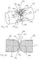
- FIG. 7Another exemplary embodiment, in which the shaft sections 8 do not have any teeth, but rather rest against one another in a force-locking manner via friction surfaces 30, is shown Fig. 7 . Otherwise, the structure corresponds to that described above, ie here too the shaft sections 8 are held in contact by tie rods or tension ropes 12. Here, too, during the deflection or bending, the adjacent shaft sections 8 roll off one another, as was described above with reference to the toothing 22.
- the friction surfaces 30are curved in the shape of an arc of a circle in accordance with the toothing 22 described above, and their surface properties are designed in such a way that slip or slipping between the shaft sections 8 is prevented.
- a geometrically defined deflection of the shaftis achieved with the toothings.
- Fig. 8shows a different type of guide for the tensioning cables 12 using the example of a single shaft section 8.
- no guide grooves 14are provided but guide channels 32 are provided in the interior of the side walls, which extend in the axial direction X through the walls.
- the guide channels 32extend through the circumferential wall sections, at whose axial ends the toothings 22 are formed. I.e. here there is an opening to the guide channels 32 in the central region of the toothings 22 educated.
- Can be seen in Fig. 8also the holes 26 through which the pull cables 24 are passed.
- Fig. 9shows a further variant of the structure of a single shaft section 8, in which guide surfaces 34 are formed on the inner circumference of the teeth 22, which protrude in the axial direction X over the axial end edges of the teeth 22.
- the guide surfaces 34are only formed on one axial end of the shaft sections 8, so that they can engage with an adjacent shaft section 8 from the opposite axial end, on which no guide surfaces 34 are formed, into the interior of the shaft section 8 and on the inner circumference laterally to the teeth 22 Plant come.
- the guide surfaces 34form a lateral guide for the adjacent shaft sections 8, so that they cannot move against one another in a direction of the axes of curvature of the toothings 22 transverse to the longitudinal axis X.
- Fig. 10shows a minimal configuration of an angled shaft area, which is formed from two mutually adjoining shaft sections 8 which can be pivoted to one another. These shaft sections 8 are in engagement with one another via toothings 22. It can be seen that in this embodiment, which enables the shaft sections 8 to roll over their teeth 22, an angle of 120 ° can be achieved.
- the arrangement of more shaft sections 8, as for example in FIG Fig. 4 shownallows a similar angle with a larger radius.
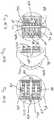
- the Figures 11 and 12show a further preferred embodiment in which the shaft area can be bent sequentially.
- the movable or bendable shaft area 4is formed from a plurality of shaft sections 8 axially adjacent to one another, which are held together by tensioning cables (not shown here), which are guided through axial holes 36 in the walls of the shaft sections 8.
- the holes 36extend axially through the walls of the shaft sections 8 on two diametrically opposite sides, similar to the guide channels 32 in FIG Fig. 8 .
- the embodiment according to FIG. 1differs from the exemplary embodiments described above Figures 11 and 12 in that there are three pairs of pull cables 24a, 24b and 24c.
- the pull cables 24are each guided in a sheath 38 in the manner of a Bowden cable.
- the sheathserves to support the pull cords 24 on the proximal first shaft section 8b.
- the sleeves 38are fixed in the feedthroughs in the proximal shaft section 8d.
- the pull cords 24care fixed on two diametrically opposite sides of the distal shaft section 8a, like the pull cords 24 according to the preceding exemplary embodiments.
- the sheaths 38 of the pull cords 24care fixed in the shaft section 8c, which forms the transition between the angled areas 42 and 44.
- the distal ends of the pull cords 24bare fixed in the shaft section 8c, while the sleeves 38 of these two pull cords 24c are supported on the shaft section 8d, which forms the transition between the angled areas 40 and 42.
- the pull cords 24aare fastened with their distal ends to the shaft section 8d and the sheaths 38 of the pull cords 24a are fixed in the shaft section 8d.
- the angled areas 40, 42 and 44can be deflected individually.
- the upper pull rope 24ashortened and at the same time the lower pull rope 24a lengthened.
- the first angled region 40 between the shaft sections 8b and 8dis curved upwards.
- the shaft sections 8 and their teeth 22roll off one another, as described above.
- the lower one of the pull cablesis 24b in Fig.
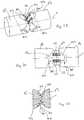
- Fig. 13shows an embodiment in which the shaft area 4 can be angled in two different directions.
- the toothings 22a between the shaft sections 8b and 8eare curved in a first direction, ie curved about axes which are directed in a first diameter direction with respect to the longitudinal axis X of the shaft.
- the teeth 22b between the shaft sections 8a and 8ewhich are also arcuate, are curved in a second direction, ie each curved about an axis which extends normal to the axes of curvature of the teeth 22a in a diametrical direction to the longitudinal axis X of the shaft.
- the sections 8e and 8bare movable relative to one another in a first pivot plane, while the shaft sections 8a and 8e are movable relative to one another in a second pivot plane 48 extending at right angles to the first pivot plane 46.
- the pivoting movementsare caused by pull cables 24, which are shown in FIG Figures 11 and 12 described manner sequentially individual shaft sections 8 can be attached, or else all of them can be attached to the distal shaft section 8a, so that the shaft can indeed be angled in two directions but only in one angled area.
- the pull cables 24 and the tension cables 12extend through the guides 14 and the holes 26 as well as suitable holes or guide channels (not shown here) in the shaft section 8e. It is also to be understood that the angled area in the embodiment according to FIG Fig.
- 13can be made longer in that a plurality of shaft elements 8e with toothings 22a and 22b rotated relative to one another can be arranged between the distal shaft section 8a and the proximal shaft section 8b.
- the individual shaft sections 8e which adjoin one anotherare each arranged rotated by 90 ° about the longitudinal axis X with respect to one another.
- FIG. 14 Shaft 2 shownhas a forceps mouth 6 at its distal end.
- the forceps jaw 6is arranged on a distally movable shaft section 8'a.
- This shaft section 8'ais connected to a shaft section 8'd, which is fixedly arranged on the rigid part of the shaft 2, via an interposed further movable shaft section 8'e.
- the shaft sections 8'b and 8'eroll off one another via teeth 22'a.
- the shaft sections 8'e and 8'aroll off one another via toothings 22'b.
- the teeth 22'a and 22'bare arranged in two planes rotated by 90 ° about the longitudinal axis of the shaft 2, so that the shaft section 8'a is angled in a plane offset by 90 ° with respect to the shaft section 8'e is to the plane in which the shaft section 8'e is angled with respect to the shaft section 8'b.
- the teeth 22'b and 22'aextend here essentially over the entire central area of the shaft sections 8 'and are only pierced by openings.
- a central lateral guideis provided in this embodiment, which are formed by protruding webs 50a and 50b.
- the web 50aextends arcuately at the proximal end of the shaft section 8'a parallel to the pivot plane between the shaft section 8'a and the shaft section 8'e.
- the web 50bextends from the proximal side of the shaft section 8'e, facing the shaft section 8'b, parallel to the pivot plane between the shaft sections 8'e and 8'b.
- the web 50aengages in a recess or groove 52a, which is formed on the distal side of the shaft section 8'e facing the shaft section 8'a.
- the web 50bengages in a groove 52b which is formed on the distal side of the shaft section 8'b facing the shaft section 8'e.
- the groove 52aextends parallel to the web 50a
- the groove 52bextends parallel to the web 50b.
- the projections or webs 50a and 50bsimultaneously serve to guide the pull cords 24'a and 24'b.
- the webs 50a and 50bare provided with channel-shaped depressions 54 on their outer or surfaces, which form cable guides.
- two pairs of pull ropes 24'a and 24'bare provided, the pair of pull ropes 24'b for deflecting the shaft section 8'e with respect to the shaft section 8'b and the pair of pulling cables 24'a for deflecting the shaft section 8 ' a with respect to the shaft section 8'e.
- the two pairs of pull cords 24 'are firmly connected to one another in the distal shaft section 8'a at the connection point 56.
- the pull cords 24'bextend through holes 57 to the side of the web 50b, while the pull cords 24'a extend through the holes 58 at the longitudinal ends of the groove 52a.
- the holes 57 and 58extend in the axial direction through the shaft section 8'e, the holes 58 'widening towards the proximal end and the holes 57 widening towards the distal end.
- holes 60are formed further inside in the middle shaft section 8'e, through which pull cables or control cables 62 extend, which form actuating cables for opening and closing the forceps mouth 6.
- the holes 60form guides for the pull cords 62, so that the pull cords 62 extend in the interior of the shaft in the central region through this in the axial direction.
- a groove or a slot 66Between the inner contact surfaces 64 between the two Toothings 22 ′′ extends a groove or a slot 66 through which, as described above with reference to the groove 52a and the holes 58, pull cables can extend.
- grooves or recesses 68is provided, through which tension cables or tension cables, as described above as tension cables 12 and tension cables 24 and 24 ', can extend.
- teeth 22 "a and 22" bwhich are opposite one another, as described above with reference to the other embodiments, mesh with one another.
- the opposing contact surfaces 64a and 64brest against one another.
- the contact surfaces 64a and 64broll off one another.
- the teeth 22 ′′ a and 22 ′′ broll in a meshing manner.
- the teeth 22 ′′achieve a form fit which ensures defined rolling without slippage.
- the contact surfaces 64hold the intermeshing teeth 22 ′′ a and 22 ′′ b at a defined distance from one another, that is, the rotation or pivot axes 70a and 70b, which form the center point of the arc along which the toothings 22 "a and 22" b extend, are kept at a defined distance from one another.
- the side flanks 72(72a, 72b), which extend normal to the contact surfaces 64 and face the teeth 22 ′′, form a lateral guide which prevents the two shaft sections 8 ′′ a and 8 ′′ b from being displaced along the pivot axes 70a and 70b
- the side surfaces of the teeth of the toothings 22 ′′ a and 22 ′′ babut these inner side flanks 72 of the contact surfaces 64 and thus form a stop that limits the lateral movement.
- FIGS. 21 to 25show a further embodiment of the invention similar to the embodiment described above.
- the end region of the shaft section 8 '''has an arcuate contact surface 64' which is curved in the shape of a circular arc around the pivot axis 70 '.
- this contact surface 64 'two parallel, arcuate toothings 22''' are formed.
- the teethare formed by alternating teeth 74 and troughs 76.
- the shape of the troughs 76is adapted to the shape of the teeth 74 so that the teeth 74a of a first shaft section 8 '''a can engage in the opposite troughs 76b of an adjacent or opposite second shaft section 8''' b and vice versa the teeth 74b of the second shaft section 8 '''b engage in the recesses 76a of the first shaft section 8''' a, as in the Figs. 23-25 is shown.
- the two shaft sections 8 '''a and 8''' broll over their contact surfaces 64'a and 64'b, while the teeth 22 '''a and 22''' b, which were shown in the preceding described manner are formed by teeth 74 and troughs 76, meshing with each other.
- a form-fitting, slip-preventing engagementis realized by the teeth 22 ''', while the contact of the contact surfaces 64' the pivot axes 70a 'and 70b' of the shaft sections 8 "'a and 8''' b holds a defined distance from one another so that the teeth 22 '''a and 22''' b can mesh with one another in the desired manner without blocking.
- the teeth 74 and troughs 76are designed so that their sides in the direction of the pivot axes 70 'are rounded. As a result, a certain centering in the direction of the pivot axes 70 ′ is achieved when the teeth 74 engage in the troughs 76.
- the arcuate contact surface 64 'preferably extends on the pitch circle of the toothings 22''' formed in this way.
Landscapes
- Health & Medical Sciences (AREA)
- Surgery (AREA)
- Life Sciences & Earth Sciences (AREA)
- Engineering & Computer Science (AREA)
- Molecular Biology (AREA)
- Biomedical Technology (AREA)
- Heart & Thoracic Surgery (AREA)
- Medical Informatics (AREA)
- Nuclear Medicine, Radiotherapy & Molecular Imaging (AREA)
- Animal Behavior & Ethology (AREA)
- General Health & Medical Sciences (AREA)
- Public Health (AREA)
- Veterinary Medicine (AREA)
- Robotics (AREA)
- Surgical Instruments (AREA)
Description
Translated fromGermanDie Erfindung betrifft ein medizinisches Instrument mit den im Oberbegriff des Anspruchs 1 angegebenen Merkmalen.The invention relates to a medical instrument with the features specified in the preamble of
Es sind medizinische Instrumente, insbesondere endoskopische Instrumente bekannt, welche einen Schaft aufweisen, welcher in zumindest einem Bereich abwinkelbar ausgebildet ist. Dabei sind Schäfte bekannt, welche einzelne Schwenkgelenke aufweisen oder aber bewegliche Schäfte, welche eine Vielzahl von gegeneinander beweglichen Schaftabschnitten aufweisen.Medical instruments, in particular endoscopic instruments, are known which have a shaft which is designed to be angled in at least one area. Shafts are known which have individual swivel joints or movable shafts which have a large number of shaft sections which can be moved relative to one another.
In jüngerer Zeit gibt es Bestrebungen, Robotersysteme für Operationen einzusetzen. Bei diesen ist es zwingend erforderlich, dass die Steuerung die genaue Instrumentenposition kennt. Bei Schäften, welche mehrere gegeneinander abwinkelbare Schaftabschnitte aufweisen, welche über Zugseile verschwenkt werden, besteht jedoch das Problem, dass die einzelnen Schaftabschnitte keine genau definierte Bewegung zueinander ausführen. Vielmehr hängt die Bewegung davon ab, wie die Abschnitte beispielsweise an angrenzendem Gewebe anliegen. Ein solches System ist für einen Roboter basiertes Operationssystem daher nicht geeignet.Efforts have recently been made to use robotic systems for operations. With these it is imperative that the control knows the exact instrument position. In the case of shafts which have a plurality of shaft sections which can be angled relative to one another and which are pivoted by means of pull cables, however, there is the problem that the individual shaft sections do not perform a precisely defined movement relative to one another. Rather, the movement depends on how the sections rest against the adjacent tissue, for example. Such a system is therefore not suitable for a robot-based operating system.
Die
Die
Ein ähnlicher Aufbau ist aus
Im Hinblick auf diese Problematik ist es Aufgabe der Erfindung, ein medizinisches Instrument mit einem Schaft, welcher zumindest zwei benachbarte gegeneinander bewegliche Schaftabschnitte aufweist, dahingehend zu verbessern, dass die Schaftabschnitte definiert zueinander verschwenken.In view of this problem, it is the object of the invention to improve a medical instrument with a shaft which has at least two adjacent shaft sections that can be moved relative to one another to the effect that the shaft sections pivot in a defined manner with respect to one another.
Diese Aufgabe wird durch ein medizinisches Instrument mit den in Anspruch 1 angegebenen Merkmalen gelöst. Bevorzugte Ausführungsformen ergeben sich aus den Unteransprüchen, der nachfolgenden Beschreibung sowie den beigefügten Figuren.This object is achieved by a medical instrument with the features specified in
Das erfindungsgemäße medizinische Instrument weist in bekannter Weise zumindest einen vorzugsweise hohlen Schaft auf, welcher zumindest zwei benachbarte gegeneinander bewegliche Schaftabschnitte aufweist. D. h. die beiden Schaftabschnitte können gegeneinander verschwenken. Erfindungsgemäß sind die zumindest zwei beweglichen Schaftabschnitte so ausgebildet, dass sie entweder über Verzahnungen formschlüssig kämmend miteinander in Eingriff sind oder reibschlüssig miteinander in Eingriff sind, sodass sie schlupffrei aufeinander abrollen. D. h. bei der Schwenkbewegung rollen die beiden beweglichen Schaftabschnitte nach Art eines Zahnradgetriebes oder reibschlüssig, schlupffrei aufeinander ab und sind stets definiert formschlüssig oder kraftschlüssig zueinander in Eingriff. D. h. die beiden Schaftabschnitte führen stets eine definierte, durch die Verzahnung oder den Reibschluss vorgegebene Bewegung relativ zueinander aus, wenn sie beispielsweise durch Zugelemente zu einer Auslenkung veranlasst werden.The medical instrument according to the invention has, in a known manner, at least one preferably hollow shaft which has at least two adjacent shaft sections which can be moved relative to one another. I.e. the two shaft sections can pivot relative to one another. According to the invention, the at least two movable shaft sections are designed in such a way that they either mesh with one another in a form-fitting manner via teeth or are in frictional engagement with one another, so that they roll off one another without slipping. I.e. During the pivoting movement, the two movable shaft sections roll off one another in the manner of a gear drive or with a friction fit, slip-free and are always in a defined form-fitting or force-fitting engagement with one another. I.e. the two shaft sections always perform a defined movement relative to one another, predetermined by the toothing or the frictional engagement, if they are caused to deflect, for example by tension elements.
Der Schaft weist eine Mehrzahl gegeneinander beweglicher Schaftabschnitte auf, von denen jeweils zwei zueinander benachbarte Schaftabschnitte über Verzahnungen oder reibschlüssig aneinander abrollend, kämmend miteinander in Eingriff sind. So werden mehrere bzw. viele Gelenkstellen zwischen den einzelnen aneinander angrenzenden bzw. zueinander benachbarten Schaftabschnitten geschaffen, wobei in diesen Gelenkstellen aufgrund des kraft- oder formschlüssigen Eingriffs stets eine definierte Abrollbewegung der einander angrenzenden Schaftabschnitte zueinander erzielt wird. Eine solche definierte Bewegung macht ein solches flexibles Instrument auch für die Roboter basierte Chirurgie verwendbar, da sich ein solcher Schaft so steuern bzw. bewegen lässt, dass die Bewegungen stets so definiert sind, dass der Steuerung die Positionierung des Schaftes und insbesondere des distalen Endes des Schaftes bekannt ist.The shaft has a plurality of mutually movable shaft sections, of which two mutually adjacent shaft sections are in meshing engagement with each other via teeth or frictionally rolling against each other. Thus, several or many articulation points are created between the individual adjoining or mutually adjacent shaft sections, with a defined rolling movement of the mutually adjacent shaft sections being achieved in these articulation points due to the non-positive or positive engagement. Such a defined movement makes such a flexible instrument for the too Robot-based surgery can be used, since such a shaft can be controlled or moved in such a way that the movements are always defined in such a way that the positioning of the shaft and in particular of the distal end of the shaft is known to the controller.
Die Verzahnungen sind so ausgebildet, dass zwei benachbarte Schaftabschnitte an ihren einander gegenüberliegenden Stirnenden mit korrespondierenden Verzahnungen versehen sind, welche so miteinander in Eingriff sind, dass die beiden Schaftabschnitte gegeneinander verschwenken können. Diese Schwenkbewegung kann insbesondere durch ein Abrollen der Schaftabschnitte aufeinander bzw. in den Verzahnungen, welche miteinander in Eingriff sind, erfolgen.The teeth are designed in such a way that two adjacent shaft sections are provided with corresponding teeth on their opposite end faces, which are in engagement with one another so that the two shaft sections can pivot relative to one another. This pivoting movement can in particular take place by the shaft sections rolling over one another or in the toothings which are in engagement with one another.
Im Falle, dass ein reibschlüssiger Eingriff der Schaftabschnitte vorgesehen ist, weisen die Schaftabschnitte jeweils Reib- bzw. Eingriffsflächen auf, welche reibschlüssig aneinander anliegen, d. h. an zwei benachbarten Schaftabschnitten sind an ihren einander gegenüberliegenden Stirnenden zueinander korrespondierende Anlageflächen bzw. Reibflächen ausgebildet, welche reibschlüssig so miteinander in Eingriff sind, dass die beiden Schaftabschnitte gegeneinander verschwenken können. Dabei rollen die Reibflächen schlupffrei aufeinander ab. Die zueinander korrespondierenden und aneinander anliegenden Reibflächen können aufgeraute oder elastische Oberflächenstrukturen aufweisen, welche einen reibschlüssigen Eingriff und ein schlupffreies Abrollen sicherstellen.In the event that a frictional engagement of the shaft sections is provided, the shaft sections each have friction or engagement surfaces which abut against one another in a frictionally engaged manner, ie. H. on two adjacent shaft sections, mutually corresponding contact surfaces or friction surfaces are formed at their opposite end faces, which frictionally engage with each other so that the two shaft sections can pivot relative to each other. The friction surfaces roll off one another without slipping. The mutually corresponding and abutting friction surfaces can have roughened or elastic surface structures which ensure frictional engagement and non-slip rolling.
Um dies zu ermöglichen, sind zumindest einzelne Verzahnungen oder Reibflächen bogenförmig ausgebildet. D. h. zumindest eine der beiden Verzahnungen oder Reibflächen, welche miteinander in Eingriff sind, ist bogenförmig ausgebildet. Bevorzugt sind beide miteinander kämmenden Verzahnungen bzw. im Eingriff befindlichen Reibflächen bogenförmig ausgebildet, sodass eine Abrollbewegung aufeinander erfolgt.In order to make this possible, at least individual toothings or friction surfaces are arcuate. I.e. at least one of the two toothings or friction surfaces which are in engagement with one another is arcuate. Both teeth meshing with one another or friction surfaces in engagement are preferably designed in an arc shape so that a rolling movement takes place on one another.
Dabei weisen die miteinander kämmenden Verzahnungen bzw. aneinander abrollenden Reibflächen an den aneinander gegenüberliegenden Stirnenden zweier benachbarter Schaftabschnitte weiter bevorzugt denselben Krümmungsradius auf. So wird eine gleichmäßige Abwinkelung erreicht.In this case, the intermeshing teeth or friction surfaces that roll against one another have the same radius of curvature at the opposite end faces of two adjacent shaft sections. In this way, an even angle is achieved.
Ferner sind die miteinander kämmenden Verzahnungen bzw. die aneinander abrollenden Reibflächen an den einander gegenüberliegenden Stirnenden zweier benachbarter Schaftabschnitte in entgegengesetzten Richtungen gekrümmt. D. h. es gibt zwei bogenförmige Außenverzahnungen, welche jeweils den Abschnitt eines Zahnrades bilden, oder bogenförmige Radabschnitte. Die Bogenform entspricht dabei, wie oben beschrieben, vorzugsweise einer Kreisbogenform. So wird ein Eingriff der zwei zueinander beabstandeten Schaftabschnitte nach Art eines Zahnradgetriebes oder ein reibschlüssiges Abrollen nach Art eines Reibradgetriebes erreicht.Furthermore, the intermeshing teeth or the friction surfaces rolling against one another are curved in opposite directions on the opposite end faces of two adjacent shaft sections. I.e. there are two arcuate external gears, which each form the section of a gear, or arcuate gear sections. As described above, the arc shape preferably corresponds to a circular arc shape. In this way, engagement of the two spaced-apart shaft sections in the manner of a gear drive or a frictional unwinding in the manner of a friction gear is achieved.
Die benachbarten Schaftabschnitte weisen an ihren einander zugewandten Stirnenden jeweils an zwei diametral entgegengesetzten Seiten eine Verzahnung bzw. Reibfläche auf. Die Verzahnungen bzw. Reibflächen erstrecken sich somit bevorzugt in zumindest zwei zueinander und zur Längsachse des Schaftabschnittes parallelen Ebenen, welche die Schwenkebenen bilden, in denen die zwei zueinander parallelen Schaftabschnitte zueinander verschwenken können. Die Verzahnungen bzw. Reibflächen erstrecken sich dabei bevorzugt in Ebenen, welche tangential oder sehnenförmig zu der Außenwandung des Schaftabschnittes angeordnet sind.The adjacent shaft sections have a toothing or friction surface on their facing ends on two diametrically opposite sides. The teeth or friction surfaces thus preferably extend in at least two planes parallel to one another and to the longitudinal axis of the shaft section, which form the pivot planes in which the two parallel shaft sections can pivot to one another. The toothings or friction surfaces preferably extend in planes which are arranged tangentially or in the form of a chord to the outer wall of the shaft section.
Insgesamt erstrecken sich die Verzahnungen bzw. Reibflächen somit vorzugsweise an den zwei diametral entgegengesetzten Seiten bogenförmig um dieselbe Achse. Dabei weisen sie wie beschrieben, eine Kreisbogenform auf. An der gegenüberliegenden Seite eines benachbarten Schaftabschnittes sind korrespondierend bevorzugt eine identisch ausgebildete Verzahnung bzw. Reibflächen gelegen.Overall, the teeth or friction surfaces thus preferably extend arcuately around the same axis on the two diametrically opposite sides. As described, they have a Circular arc shape. Correspondingly, identically designed toothing or friction surfaces are correspondingly preferably located on the opposite side of an adjacent shaft section.
Besonders bevorzugt weist der Schaft zumindest drei gegeneinander bewegliche Schaftabschnitte auf, von denen die jeweils benachbarten Schaftabschnitte über Verzahnungen kämmend oder reibschlüssig aneinander abrollend miteinander in Eingriff sind. Dabei können die Verzahnungen oder Reibflächen in der vorangehend beschriebenen Weise ausgebildet sein. Bei dieser bevorzugten Ausführungsform sind weiter bevorzugt der erste und der zweite Schaftabschnitt in einer ersten Schwenkebene und der zweite und der dritte Schaftabschnitt in einer zweiten Schwenkebene zueinander beweglich. D. h. die Schwenkebenen zwischen den einzelnen Schaftabschnitten wechseln einander ab, sodass eine Beweglichkeit in verschiedenen Richtungen zueinander erreicht wird. Bevorzugt erstrecken sich die erste und die zweite Schwenkebene normal zueinander, sodass sich die einzelnen Schwenkebenen jeweils um 90° bezüglich der Längsachse des Schaftes versetzt zueinander abwechseln. Dadurch wird eine Auslenkung des Schaftes in allen Raumrichtungen möglich, in dem die Schwenkbewegungen in den zwei Richtungen kombiniert bzw. überlagert werden. Um diese abwechselnde Ausrichtung der Schwenkebenen zwischen den einzelnen Schaftabschnitten zu erreichen, sind vorzugsweise die Erstreckungsebenen, in welchen die bogenförmigen Verzahnungen bzw. Reibflächen gelegen sind, von einer Schnittstelle zur nächsten jeweils um 90° versetzt zueinander angeordnet. D. h. zwischen dem ersten und dem zweiten Schaftabschnitt sind die bogenförmigen Verzahnungen bzw. Reibflächen in Ebenen parallel zu der ersten Schwenkebene angeordnet, während die bogenförmigen Verzahnungen bzw. Reibflächen zwischen dem zweiten und dritten Schaftabschnitt parallel zu der zweiten Schwenkebene angeordnet sind. Bei mehr als drei Schaftabschnitten setzt sich dies dann entsprechend fort.Particularly preferably, the shaft has at least three shaft sections which can move relative to one another, of which the respectively adjacent shaft sections are in meshing engagement with one another via teeth or rolling against one another in a frictional manner. The toothings or friction surfaces can be designed in the manner described above. In this preferred embodiment, the first and the second shaft section are further preferably movable relative to one another in a first pivot plane and the second and the third shaft section in a second pivot plane. I.e. the swivel planes between the individual shaft sections alternate so that mobility in different directions is achieved. The first and second pivot planes preferably extend perpendicular to one another, so that the individual pivot planes alternate with one another offset by 90 ° with respect to the longitudinal axis of the shaft. This enables the shaft to be deflected in all spatial directions by combining or superimposing the pivoting movements in the two directions. In order to achieve this alternating alignment of the pivot planes between the individual shaft sections, the planes of extension in which the arcuate toothings or friction surfaces are located are arranged offset from one another by 90 ° from one interface to the next. I.e. Between the first and the second shaft section, the curved teeth or friction surfaces are arranged in planes parallel to the first pivot plane, while the curved teeth or friction surfaces between the second and third shaft sections are arranged parallel to the second pivot plane. If there are more than three shaft sections, this continues accordingly.
Die Verzahnungen bzw. Reibflächen sind dabei bogenförmig ausgebildet und die Verzahnungen bzw. Reibflächen zwischen dem ersten und dem zweiten Abschnitt sind bevorzugt um Achsen, d. h. besonders bevorzugt um dieselbe Achse gekrümmt, welche sich normal zu den Achsen bzw. der Achse erstrecken, um welche die Verzahnungen bzw. Reibflächen zwischen dem zweiten und dem dritten Schaftabschnitt gekrümmt sind. Diese Achsen, um welche die Verzahnungen bzw. Reibflächen gekrümmt sind, erstrecken sich normal zu den jeweiligen Schwenkebenen, in welchen die Schwenkbewegungen zwischen den zwei benachbarten Schaftabschnitten ausgeführt werden.The teeth or friction surfaces are arcuate and the teeth or friction surfaces between the first and the second section are preferably about axes, ie. H. particularly preferably curved around the same axis, which extend normal to the axes or the axis around which the teeth or friction surfaces are curved between the second and the third shaft section. These axes, around which the toothings or friction surfaces are curved, extend normal to the respective pivot planes in which the pivot movements between the two adjacent shaft sections are carried out.
Gemäß einer besonders bevorzugten Ausführungsform sind die zumindest zwei beweglichen Schaftabschnitte über Verzahnungen kämmend miteinander in Eingriff und rollen gleichzeitig über bogenförmige Anlageflächen aneinander ab. Das heißt, an den zwei Schaftabschnitten sind an einander zugewandten Seiten jeweils zumindest eine bogenförmige Verzahnung und zumindest eine bogenförmige Anlagefläche ausgebildet. Dabei greifen die Verzahnungen ineinander ein und die bogenförmigen Anlageflächen, welche einander zugewandt sind, liegen aneinander an. Diese Ausgestaltung hat den Vorteil, dass über die bogenförmigen Anlageflächen die Verzahnungen beim Verschwenken in einem definierten Abstand zueinander gehalten werden, das heißt, es wird ein konstanter Achsabstand zwischen den Schwenkachsen der beiden Schaftabschnitte eingehalten. Dieser wird durch die bogenförmigen Anlageflächen definiert.According to a particularly preferred embodiment, the at least two movable shaft sections are in meshing engagement with one another via toothings and simultaneously roll off one another via curved contact surfaces. That is to say, at least one arcuate toothing and at least one arcuate contact surface are formed on the sides facing one another on the two shaft sections. The teeth mesh with one another and the arcuate contact surfaces which face one another rest against one another. This embodiment has the advantage that the toothings are kept at a defined distance from one another during pivoting via the arcuate contact surfaces, that is, a constant axial distance is maintained between the pivot axes of the two shaft sections. This is defined by the curved contact surfaces.
Für den Fall, dass mehr als zwei Abschnitte vorgesehen sind, ist weiter bevorzugt eine derartige Ausgestaltung bestehend aus bogenförmigen Verzahnungen und bogenförmigen Anlageflächen, welche für einen konstanten Achsabstand sorgen, jeweils zwischen den aneinander angrenzenden Schaftabschnitten ausgebildet. Dabei können die Verzahnungen in der vorangehend beschriebenen Weise ausgestaltet und angeordnet sein.In the event that more than two sections are provided, such a configuration consisting of arcuate toothings and arcuate contact surfaces, which ensure a constant axial spacing, is preferably formed between the adjacent shaft sections. The gears be designed and arranged in the manner described above.
Weiter bevorzugt ist gleichzeitig eine seitliche Führung vorgesehen, welche ein Verschieben aneinander angrenzender Schaftabschnitte in Richtung der Schwenkachse verhindert. Eine solche seitliche Führung kann durch eine an die bogenförmige Anlagefläche angrenzende, das heißt sich quer zu der Anlagefläche erstreckende Wandung bzw. Flanke gebildet werden. Beispielsweise können die Köpfe der Zähne in radialer Richtung über eine angrenzende Anlagefläche vorstehen, sodass zwischen den Zähnen Seitenflanken entstehen, an welchen die überstehenden Zähne eines gegenüberliegenden Schaftabschnittes bei seitlicher Bewegung anstoßen, sodass diese begrenzt oder verhindert wird.Furthermore, a lateral guide is preferably provided at the same time, which prevents a displacement of adjoining shaft sections in the direction of the pivot axis. Such a lateral guide can be formed by a wall or flank adjoining the curved contact surface, that is to say extending transversely to the contact surface. For example, the heads of the teeth can protrude in the radial direction over an adjoining contact surface, so that side flanks are created between the teeth, against which the protruding teeth of an opposite shaft section abut during lateral movement so that this is limited or prevented.
Weiter bevorzugt weist jeder Schaftabschnitt zumindest eine bogenförmige Anlagefläche und eine Verzahnung auf, wobei die bogenförmige Anlagefläche zweckmäßigerweise parallel zu der Verzahnung gekrümmt ist. Dadurch wird erreicht, dass in jeder Winkelposition beim Verschwenken der Achsabstand zwischen den Schaftabschnitten konstant gehalten wird. Besonders bevorzugt hat die bogenförmige Anlagefläche denselben Radius bzw. Krümmungsradius wie der Teilkreis der Verzahnung.More preferably, each shaft section has at least one arcuate contact surface and a toothing, the arcuate contact surface expediently being curved parallel to the toothing. This ensures that the axial distance between the shaft sections is kept constant in every angular position when pivoting. The arcuate contact surface particularly preferably has the same radius or radius of curvature as the pitch circle of the toothing.
Um die einzelnen Schaftabschnitte mit ihren Verzahnungen oder Reibflächen in Anlage bzw. in Eingriff zu halten, sind Spannelemente vorgesehen, welche sich in Axialrichtung des Schaftes erstrecken. Dies sind Spannseile, welche über Federelemente so vorgespannt sind, dass die Schaftabschnitte auch bei Schwenkbewegungen stets in Anlage gehalten werden, sodass Verzahnungen kämmend in Eingriff bleiben bzw. Reibflächen reibschlüssig in Anlage gehalten werden, sodass ein Abrollen ohne Schlupf stattfinden kann. Auch können die Schaftabschnitte über die nachfolgend beschriebenen Zugelemente in Anlage gehalten werden.In order to keep the individual shaft sections with their toothing or friction surfaces in contact or in engagement, clamping elements are provided which extend in the axial direction of the shaft. These are tension ropes which are pretensioned by spring elements in such a way that the shaft sections are always held in contact even during pivoting movements, so that the teeth remain in meshing engagement or friction surfaces are held in contact with frictional engagement so that rolling takes place without slippage can. The shaft sections can also be held in abutment via the tension elements described below.
Die Auslenkung der einzelnen Schaftabschnitte erfolgt Zugdrähte bzw. Zugseile. Dazu sind zumindest zwei sich in Längsrichtung des Schaftes erstreckende Zugdrähte vorgesehen, welche mit ihrem distalen Ende an zwei diametral entgegengesetzten Seiten eines distalen Schaftabschnittes befestigt sind. Diese beiden diametral entgegengesetzten Seiten, an welchen die Zugdrähte befestigt und gelegen sind, befinden sich dabei bevorzugt in der Schwenkebene, innerhalb welcher die jeweiligen Schaftabschnitte zueinander verschwenken sollen. Durch Zug an einem der Zugdrähte erfolgt dann eine Auslenkung des Schaftes in die radiale Richtung, an welcher der sich verkürzende Zugdraht gelegen ist. Bei Zug an dem anderen Zugdraht erfolgt eine Auslenkung in die entgegengesetzte Richtung. Der jeweils zweite Zugdraht wird entsprechend gelockert bzw. gelenkt. Diese Auslenkung über Zugdrähte entspricht im Wesentlichen der von flexiblen Endoskopen her bekannten Auslenkung.The individual shaft sections are deflected using pull wires or pull cables. For this purpose, at least two puller wires extending in the longitudinal direction of the shaft are provided, which are attached with their distal end to two diametrically opposite sides of a distal shaft section. These two diametrically opposite sides, on which the puller wires are attached and located, are preferably located in the pivot plane within which the respective shaft sections are intended to pivot relative to one another. By pulling on one of the puller wires, the shaft is then deflected in the radial direction on which the shortening puller wire is located. When the other pull wire is pulled, it is deflected in the opposite direction. The second pull wire is loosened or steered accordingly. This deflection via tension wires essentially corresponds to the deflection known from flexible endoscopes.
Um eine Auslenkung in zwei unterschiedlichen, insbesondere um 90° zueinander versetzten Raumrichtungen zu ermöglichen, ist es weiter bevorzugt, zumindest vier Zugdrähte vorzusehen, welche jeweils um 90° bezüglich der Längsachse versetzt an einem distalen Schaftabschnitt befestigt sind. Dabei liegen zwei der Zugdrähte diametral entgegengesetzt bevorzugt in der ersten beschrieben Schwenkebene und die zwei anderen Zugdrähte diametral entgegengesetzt in einer um 90° um die Längsachse des Schaftes versetzten Schwenkebene. D. h. zwei der Zugdrähte sind für die Schwenkbewegung in der ersten Schwenkebene und zwei der Zugdrähte für die Schwenkbewegung in der zweiten Schwenkebene zuständig. Wenn im Schaft mehrere gegeneinander bewegliche Schaftabschnitte angeordnet sind, welche abwechselnd in den zwei unterschiedlichen Schwenkebenen zueinander beweglich sind, wird bei Betätigung des ersten Paares von Zugdrähten eine Schwenkbewegung jeweils nur in jedem zweiten Schwenkgelenk erfolgen, welches eine Schwenkbewegung in dieser Schwenkebene zulässt. Bei Betätigung des anderen Paares von Zugdrähten erfolgt dann eine Schwenkbewegung in der normal gerichteten Schwenkebene in den jeweils anderen Schwenkgelenken.In order to enable a deflection in two different spatial directions, in particular offset by 90 ° from one another, it is further preferred to provide at least four puller wires which are each attached to a distal shaft section offset by 90 ° with respect to the longitudinal axis. Two of the pull wires are located diametrically opposite, preferably in the first described swivel plane, and the two other pull wires are located diametrically opposite in a swivel plane offset by 90 ° about the longitudinal axis of the shaft. I.e. two of the pull wires are responsible for the swivel movement in the first swivel plane and two of the pull wires are responsible for the swivel movement in the second swivel plane. When a plurality of mutually movable shaft sections are arranged in the shaft, which mutually movable alternately in the two different pivot planes are, upon actuation of the first pair of pull wires, a pivoting movement will only take place in every second pivot joint, which allows a pivoting movement in this pivoting plane. When the other pair of pull wires is actuated, a pivoting movement then takes place in the normally directed pivot plane in the other pivot joints.
Vorzugsweise sind vier Zugdrähte vorgesehen, welche an ihren distalen Enden miteinander verbunden sind. Die Verbindung der Zugdrähte erleichtert die Montage. Insbesondere sind alle Zugdrähte bzw. Steuerseile in einem distalen Schaftabschnitt, d. h. dem letzten beweglichen Schaftabschnitt am distalen Ende miteinander verbunden. So können die Zugdrähte ausgehend vom distalen Ende einfach durch die vorgesehenen Führungen und Ausnehmungen der sich proximalseitig anschließenden Schaftabschnitte bis zum proximalen Ende gefädelt werden. Bevorzugt können die vier Zugdrähte dabei als zwei U-förmige Schlaufen ausgebildet sein, welche sich kreuzen und in ihrem Kreuzungs- bzw. Mittelpunkt miteinander verbunden sind. Diese Verbindung kann beispielsweise durch Verschweißen oder Verkleben oder Verklemmen erfolgen.Preferably four puller wires are provided which are connected to one another at their distal ends. The connection of the pull wires facilitates assembly. In particular, all pull wires or control cables are in a distal shaft section, i. H. connected to the last movable shaft section at the distal end. Thus, starting from the distal end, the puller wires can simply be threaded through the guides and recesses provided in the shaft sections adjoining the proximal end to the proximal end. The four puller wires can preferably be designed as two U-shaped loops which intersect and are connected to one another at their intersection or center point. This connection can be made, for example, by welding or gluing or clamping.
Wenn die Zugdrähte nicht am distalen Schaftabschnitt angelenkt werden, sondern an weiter proximalwärts gelegenen Schaftabschnitten, so wird es auch möglich, über entsprechende Paare von Zugdrähten definiert einzelne Schaftabschnitte gegeneinander zu bewegen. D. h. für jedes Gelenk bzw. jeden bewegbaren Schaftabschnitt wird ein Paar von Zugdrähten vorgesehen, welches in der Schwenkebene dieses Schaftabschnittes an diametral entgegengesetzten Seiten des Schaftabschnittes befestigt ist. So kann eine definierte schlangenförmige Auslenkung des Instrumentes erreicht werden.If the puller wires are not hinged to the distal shaft section, but rather to shaft sections located further proximally, then it is also possible to move individual shaft sections against one another in a defined manner via corresponding pairs of puller wires. I.e. For each joint or each movable shaft section, a pair of pull wires is provided which is fastened in the pivot plane of this shaft section on diametrically opposite sides of the shaft section. In this way, a defined, serpentine deflection of the instrument can be achieved.
In denjenigen Schaftabschnitten, welche proximalseitig des distalen Schaftabschnittes bzw. desjenigen Schaftabschnittes gelegen sind, an welchem die jeweiligen Zugdrähte befestigt sind, sind weiter bevorzugt Führungen für diese Zugdrähte ausgebildet. So wird erreicht, dass die Zugdrähte definiert in der Schaftwandung bzw. an der Schaftwandung geführt werden. Darüber hinaus bieten die Führungen Anlagepunkte, welche das Auslenken in definierter Weise durch Zug an den Zugdrähten erst ermöglichen. So werden Kraftangriffspunkte für die Zugdrähte geschaffen.In those shaft sections which are located on the proximal side of the distal shaft section or that shaft section to which the respective puller wires are attached, guides for these puller wires are furthermore preferably formed. This ensures that the pull wires are guided in a defined manner in the shaft wall or on the shaft wall. In addition, the guides offer contact points which enable deflection in a defined manner by pulling on the tension wires. This creates force application points for the puller wires.
Gemäß einer weiteren bevorzugten Ausführungsform weisen die zumindest zwei benachbarten zueinander beweglichen Schaftabschnitte eine Seitenführung auf. D. h. die zwei Schaftabschnitte sind über eine sich parallel zur Schwenkebene erstreckende Seitenführung miteinander in Eingriff. Die Seitenführung kann von einer oder mehreren Führungsflächen gebildet werden. Vorzugsweise steht zumindest ein Steg von einem der Schaftabschnitte vor und greift in eine gegenüberliegende Nut ein. Dabei erstrecken sich der Steg und die Nut in der Schwenkebene bzw. parallel zu der Schwenkebene. Gemäß einer ersten bevorzugten Ausführungsform ist lediglich eine Seitenführung in Form eines Steges vorgesehen, welcher vorzugsweise im Mittelbereich gelegen ist. Gemäß einer alternativen Ausführungsform können auch zwei in Durchmesserrichtung voneinander beabstandete Seitenführungen, welche sich parallel zueinander erstrecken, vorgesehen sein.According to a further preferred embodiment, the at least two adjacent shaft sections that are movable relative to one another have a lateral guide. I.e. the two shaft sections are in engagement with one another via a lateral guide extending parallel to the pivot plane. The lateral guide can be formed by one or more guide surfaces. At least one web preferably protrudes from one of the shaft sections and engages in an opposite groove. The web and the groove extend in the pivot plane or parallel to the pivot plane. According to a first preferred embodiment, only one lateral guide in the form of a web is provided, which is preferably located in the central area. According to an alternative embodiment, two lateral guides which are spaced apart from one another in the diameter direction and extend parallel to one another can also be provided.
Wie oben ausgeführt, ist der Schaft des medizinischen Instrumentes gemäß einer bevorzugten Ausführungsform hohl ausgebildet. Dazu können die zumindest zwei beweglichen Schaftabschnitte jeweils einen sich in axialer Richtung durch den Schaftabschnitt hindurch erstreckenden zentralen Hohlraum aufweisen, wobei die Hohlräume der mehreren Schaftabschnitte miteinander fluchten. Auf diese Weise wird durch die beweglichen Schaftabschnitte hindurch, ein durchgehender, sich in axialer Richtung erstreckender Hohlraum geschaffen. Dieser Hohlraum bzw. Kanal erlaubt die Führung und optionale Befestigung weiterer Baugruppen, wie beispielsweise Lichtwellenleiter, Bildleiter, elektrische Leitungen, Schläuche oder Rohre zum Führen von Medien, wie Gas oder Flüssigkeiten, Schläuche oder Rohre zum Führen von Anwendungswerkzeugen wie Zangen, Körbe, Laserfasern, Kraftübertragungselemente wie Stangen, Züge, Mikroantriebe wie Piezoantriebe, auf Formgedächtnis basierende Aktoren, elektroaktive Polymeraktoren, dieleketrische Elastomeraktoren, magnetostriktive Antriebe, magnetorheologische Antriebe, Pneumatik- und Hydraulikantriebe, sowie elektromagnetische Antriebe usw.As stated above, according to a preferred embodiment, the shaft of the medical instrument is hollow. For this purpose, the at least two movable shaft sections can each have a central cavity extending through the shaft section in the axial direction, the cavities of the plurality of shaft sections being aligned with one another. In this way, through the movable shaft sections, a continuous, in created cavity extending in the axial direction. This cavity or channel allows the guidance and optional attachment of further assemblies, such as optical waveguides, image conductors, electrical cables, hoses or pipes for guiding media such as gas or liquids, hoses or pipes for guiding application tools such as pliers, baskets, laser fibers, Force transmission elements such as rods, trains, micro drives such as piezo drives, actuators based on shape memory, electroactive polymer actuators, dielectric elastomer actuators, magnetostrictive drives, magnetorheological drives, pneumatic and hydraulic drives, as well as electromagnetic drives, etc.
Nachfolgend wird die Erfindung beispielhaft anhand der beigefügten Figuren beschrieben. In diesen zeigt:
- Fig. 1
- eine schematische perspektivische Gesamtansicht des distalen Endes eines medizinisches Instrumentes,
- Fig. 2
- eine Ansicht gemäß
Fig. 1 ohne umhüllenden Schutzschlauch, - Fig. 3
- schematisch den Schaftaufbau des Instrumentes gemäß
Fig. 1 ,und 2 - Fig. 4
- schematisch die Abwinklung des Schaftes gemäß
Fig. 1 - 3 , - Fig. 5
- eine schematische Seitenansicht einer zweiten Ausführungsform der Erfindung,
- Fig. 6
- die Abwinklung des Schaftes gemäß
Fig. 5 , - Fig. 7
- schematisch den Aufbau eines Schaftes gemäß einer dritten Ausführungsform der Erfindung,
- Fig. 8
- einen Schaftabschnitt gemäß einer weiteren Ausführungsform der Erfindung,
- Fig. 9
- einen Schaftabschnitt einer weiteren Ausführungsform der Erfindung,
- Fig. 10
- schematisch die Abwinklung zweier beweglicher Schaftabschnitte,
- Fig. 11
- schematisch in einer perspektivischen Ansicht einen seriell abwinkelbaren Schaft gemäß der Erfindung,
- Fig. 12
- eine Seitenansicht des Schaftes gemäß
Fig. 11 , - Fig. 13
- schematisch einen in zwei Richtungen abwinkelbaren Schaft,
- Fig. 14
- schematisch den Aufbau eines Schaftes gemäß einer weiteren Ausführungsform der Erfindung,
- Fig. 15
- eine Detailansicht des Schaftes gemäß
Fig. 14 ohne den distalen Schaftabschnitt, - Fig. 16A - 16B
- in zwei entgegengesetzten Draufsichten und einer Seitenansicht den zentralen beweglichen Schaftabschnitt der Ausführungsform gemäß
Fig. 14 und 15 , - Fig. 17
- schematisch einen Endbereich eines Schaftabschnittes gemäß einer weiteren Ausführungsform der Erfindung,
- Fig. 18
- eine Vergrößerung des Ausschnittes XVIII in
Fig. 17 , - Fig. 19
- schematisch in einer perspektivischen Ansicht die Anlage zweier Schaftabschnitte gemäß
Fig. 17 ,und 18 - Fig. 20
- eine Schnittansicht der Anordnung in
Fig. 19 , - Fig. 21
- schematisch einen Endbereich eines Schaftabschnittes gemäß einer weiteren Ausführungsform der Erfindung,
- Fig. 22
- vergrößert den Ausschnitt XXII in
Fig. 21 , - Fig. 23
- schematisch in einer perspektivischen Ansicht die Anlage zweier Schaftabschnitte gemäß
Fig. 21 ,und 22 - Fig. 24
- eine Draufsicht auf die Anordnung gemäß
Fig. 23 , und - Fig. 25
- eine Schnittansicht entlang der Linie XXV-XXV in
Fig. 24 .
- Fig. 1
- a schematic perspective overall view of the distal end of a medical instrument,
- Fig. 2
- a view according to
Fig. 1 without enveloping protective hose, - Fig. 3
- schematically the shaft structure of the instrument according to FIG
Figs. 1 and 2 , - Fig. 4
- schematically the bending of the shaft according to
Figs. 1-3 , - Fig. 5
- a schematic side view of a second embodiment of the invention,
- Fig. 6
- the bending of the shaft according to
Fig. 5 , - Fig. 7
- schematically the structure of a shaft according to a third embodiment of the invention,
- Fig. 8
- a shaft section according to a further embodiment of the invention,
- Fig. 9
- a shaft section of a further embodiment of the invention,
- Fig. 10
- schematically the angling of two movable shaft sections,
- Fig. 11
- schematically in a perspective view a serially angled shaft according to the invention,
- Fig. 12
- a side view of the shaft according to
Fig. 11 , - Fig. 13
- schematically a shaft that can be bent in two directions,
- Fig. 14
- schematically the structure of a shaft according to a further embodiment of the invention,
- Fig. 15
- a detailed view of the shaft according to
Fig. 14 without the distal shaft section, - Figures 16A-16B
- in two opposite plan views and a side view the central movable shaft portion according to the embodiment
Figures 14 and 15 , - Fig. 17
- schematically an end region of a shaft section according to a further embodiment of the invention,
- Fig. 18
- an enlargement of section XVIII in
Fig. 17 , - Fig. 19
- schematically in a perspective view the system of two shaft sections according to FIG
Figures 17 and 18 , - Fig. 20
- a sectional view of the arrangement in
Fig. 19 , - Fig. 21
- schematically an end region of a shaft section according to a further embodiment of the invention,
- Fig. 22
- enlarges the section XXII in
Fig. 21 , - Fig. 23
- schematically in a perspective view the system of two shaft sections according to FIG
Figures 21 and 22 , - Fig. 24
- a plan view of the arrangement according to
Fig. 23 , and - Fig. 25
- a sectional view along the line XXV-XXV in
Fig. 24 .
Das erfindungsgemäße medizinische Instrument ist vorzugsweise ein endoskopisches Instrument und weist in bekannter Weise einen Schaft 2 auf, dessen distaler Schaftbereich 4 anwinkelbar ausgebildet ist. Am distalen Ende des Schaftes ist ein Zangenmaul 6 angeordnet. Das Zangenmaul 6 ist in bekannter Weise vom proximalen Ende des Schaftes 2 (das proximale Ende ist hier nicht gezeigt) über eine Handhabe oder elektrische Antriebe bewegbar. Dazu können im Inneren des Schaftes 2 Betätigungselemente, wie Zug- oder Druckelemente in axialer Richtung X verlaufen.The medical instrument according to the invention is preferably an endoscopic instrument and, in a known manner, has a
Der distale Schaftbereich 4 besteht aus mehreren axial aneinander angrenzend angeordneten Schaftabschnitten 8. Die Schaftabschnitte 8 sind an ihrem Außenumfang, wie in
Die einzelnen Schaftabschnitte 8 sind jeweils über Verzahnungen 22 miteinander in Eingriff. Die Verzahnungen 22 sind an den einzelnen Schaftelementen 8 an zwei diametral entgegengesetzten Seiten ausgebildet und zwar an den Seiten, an welchen auch die Führungsnuten 14 gelegen sind, durch welche sich die Spannseile 12 erstrecken. Die Verzahnungen 22 sind jeweils bogenförmig ausgebildet, sodass sie den Abschnitt eines Zahnrades bilden. Die Achsen, um die die Verzahnungen 22 bogenförmig gekrümmt sind, erstrecken sich normal zu der Längsachse X des Schaftes 2 in diametraler Richtung durch die Schaftabschnitte 8 hindurch und kreuzen somit die Spannseile 12. Die Verzahnungen 22 erlauben es, dass die Schaftabschnitte 8, welche zueinander benachbart sind, bzw. aneinander angrenzen, über die Verzahnungen 22 aufeinander abrollen können. So kann der Schaftbereich 4, wie in
Die Krümmung wird durch zwei Zugzeile 24 erreicht, welche sich durch Führungen in Form von Löchern 26 in den Wandungen der Schaftabschnitte 8 in axialer Richtung erstrecken. Die beiden Zugsseile 24 sind an zwei diametral entgegensetzten Seiten der Schaftabschnitte 8 um 90° versetzt zu den Seiten, an welchen die Spannseile 12 angeordnet sind, angeordnet. Eine diametrale Verbindungslinie zwischen den Zugseilen 24 erstreckt sich somit normal zu den Achsen, um welche die Verzahnungen 22 gekrümmt sind. Die Zugseile 24 sind ebenfalls am distalseitigen Schaftabschnitt 8a, welcher am nächsten zu dem Zangenmaul 6 und somit dem distalen Ende des Schaftes 2 gelegen ist, fest verbunden. Sie erstrecken sich durch den Schaft 2 bis zum proximalen Ende, welches hier nicht gezeigt ist und sind dort in bekannter Weise mit Antriebselementen oder Betätigungselementen verbunden. Je nachdem, welches der Zugseile 24 in proximaler Richtung gezogen und somit in dem Schaftbereich 4 verkürzt wird, kann der Schaftbereich 4 zu einer Richtung hin ausgelenkt werden. Das diametral entgegengesetzt gelegene Zugseil 24 wird entsprechend gelängt. Eine Auslenkung in die andere Richtung erfolgt entsprechend durch Kürzung des anderen Zugseils 24. Die Zugseile 24 könnten auch als Zug-Druckelemente ausgebildet sein. Dann könnte auf eines der Zugseile verzichtet werden. In dem Fall könnte dann eine Auslenkung in die eine Richtung durch Druck und die Auslenkung in die entgegengesetzte Richtung durch Zug des Zug-Druckelementes erfolgen.The curvature is achieved by two
Auch ist eine Ausführungsform denkbar, bei welcher eine Auslenkung nur in eine Richtung möglich ist. Eine solche Ausführungsform ist in
Ein weiteres Ausführungsbeispiel, bei welchem die Schaftabschnitte 8 keine Verzahnungen aufweisen sondern kraftschlüssig über Reibflächen 30 aneinander anliegen, zeigt
Die
Durch die drei Paare von Zugseilen 24a, 24b und 24c können in dem Schaftbereich 4 drei Abwinkelbereiche 40, 42 und 44 realisiert werden. Die Zugseile 24c sind an zwei diametral entgegengesetzten Seiten des distalen Schaftabschnittes 8a festgelegt, wie die Zugseile 24 gemäß der vorangehenden Ausführungsbeispiele. Gleichzeitig sind die Hüllen 38 der Zugseile 24c in dem Schaftabschnitt 8c, welcher den Übergang zwischen den Abwinkelbereichen 42 und 44 bildet, fixiert. Die Zugseile 24b sind mit ihren distalen Enden in dem Schaftabschnitt 8c fixiert, während sich die Hüllen 38 dieser beiden Zugseile 24c an dem Schaftabschnitt 8d abstützen, welcher den Übergang zwischen den Abwinkelbereichen 40 und 42 bildet. Die Zugseile 24a sind mit ihren distalen Enden an dem Schaftabschnitt 8d befestigt und die Hüllen 38 der Zugseile 24a sind in dem Schaftabschnitt 8d festgelegt. Durch diese Ausgestaltung können die Abwinkelbereiche 40, 42 und 44 individuell ausgelenkt werden. Um die in den
Anhand der
Insbesondere ist bei dieser Ausführungsform eine zentrale Seitenführung vorgesehen, welche durch vorstehende Stege 50a und 50b gebildet werden. Der Steg 50a erstreckt sich bogenförmig am proximalen Ende des Schaftabschnittes 8'a parallel zu der Schwenkebene zwischen dem Schaftabschnitt 8'a und dem Schaftabschnitt 8'e. Der Steg 50b erstreckt sich ausgehend von der proximalen Seite des Schaftabschnittes 8'e, dem Schaftabschnitt 8'b zugewandt, parallel zu der Schwenkebene zwischen den Schaftabschnitten 8'e und 8'b. Der Steg 50a greift in eine Ausnehmung bzw. Nut 52a ein, welche an der dem Schaftabschnitt 8'a zugewandten Distalseite des Schaftabschnittes 8'e ausgebildet ist. Entsprechend greift der Steg 50b in eine Nut 52b ein, welche an der dem Schaftabschnitt 8'e zugewandten Distalseite des Schaftabschnittes 8'b ausgebildet ist. Die Nut 52a erstreckt sich dabei parallel zu dem Steg 50a, die Nut 52b erstreckt sich parallel zu dem Steg 50b. Durch den Eingriff der Stege 50 in die zugehörigen Nuten 52 wird in dem jeweiligen Gelenk eine Seitenführung quer zu der jeweiligen Schwenkebene realisiert.In particular, a central lateral guide is provided in this embodiment, which are formed by protruding
Die Vorsprünge bzw. Stege 50a und 50b dienen gleichzeitig der Führung der Zugseile 24'a und 24'b. Dazu sind die Stege 50a und 50b auf ihren Außen- bzw. Oberflächen mit rinnenförmigen Vertiefungen 54 versehen, welche Seilführungen bilden. Hier sind zwei Paare von Zugseilen 24'a und 24'b vorgesehen, wobei das Paar von Zugseilen 24'b zur Auslenkung des Schaftabschnittes 8'e gegenüber dem Schaftabschnitt 8'b und das Paar von Zugseilen 24'a zur Auslenkung des Schaftabschnittes 8'a gegenüber dem Schaftabschnitt 8'e dienen. Die beiden Paare von Zugseilen 24' sind in dem distalen Schaftabschnitt 8'a an dem Verbindungspunkt 56 fest miteinander verbunden. Dies erleichtert die Montage, da die Zugseile 24' vom distalen Ende durch sämtliche Schaftabschnitte 8 gefädelt werden können. Die Zugseile 24'b erstrecken sich durch Löcher 57 seitlich des Steges 50b, während sich die Zugseile 24'a durch die Löcher 58 an den Längsenden der Nut 52a erstrecken. Die Löcher 57 und 58 erstrecken sich in axialer Richtung durch den Schaftabschnitt 8'e hindurch, wobei die Löcher 58' sich zum proximalen Ende hin und die Löcher 57 zum distalen Ende hin erweitern. Darüber hinaus sind weiter innenliegend Löcher 60 in dem mittleren Schaftabschnitt 8'e ausgebildet, durch welche sich Zugseile- bzw. Steuerseile 62 erstrecken, welche Betätigungsseile zum Öffnen und Schließen des Zangenmaules 6 bilden. Die Löcher 60 bilden Führungen für die Zugseile 62, sodass sich die Zugseile 62 im Inneren des Schaftes im Zentralbereich durch diesen in axialer Richtung hindurch erstrecken.The projections or
Hinsichtlich der vorangehend beschriebenen Ausführungsformen ist zu verstehen, dass alternativ bei allen gezeigten Ausführungsbeispielen eine Ausgestaltung mit Reibflächen, wie sie in
Bei der in
Wenn, wie in
Die Seitenflanken 72 (72a, 72b), welche sich normal zu den Anlageflächen 64 erstrecken und den Verzahnungen 22" zugewandt sind, bilden eine seitliche Führung, welche ein Verschieben der beiden Schaftabschnitte 8"a und 8"b entlang der Schwenkachsen 70a und 70b verhindern. Die Seitenflächen der Zähne der Verzahnungen 22"a und 22"b stoßen an diese inneren Seitenflanken 72 der Anlageflächen 64 an und bilden somit ein die seitliche Bewegung begrenzenden Anschlag.The side flanks 72 (72a, 72b), which extend normal to the contact surfaces 64 and face the
Die
Die Zähne 74 und Mulden 76 sind so ausgebildet, dass ihre in Richtung der Schwenkachsen 70' gelegenen Seiten gerundet ausgebildet sind. Dadurch wird eine gewisse Zentrierung in Richtung der Schwenkachsen 70' beim Eingriff der Zähne 74 in die Mulden 76 erreicht. Auch bei dieser Ausführungsform erstreckt sich die bogenförmige Anlagefläche 64' vorzugsweise auf dem Teilkreis der so gebildeten Verzahnungen 22'''.The
Es ist zu verstehen, dass auch bei den Ausführungsformen gemäß
Claims (18)
- A medical instrument with a shank (2) which comprises at least two adjacent shank sections (8) which are movable to one another, wherein the at least two movable shank sections (8) frictionally roll on one another or are meshingly engaged with one another via toothings (22, 22'; 22"; 22'''), wherein the toothings (22, 22'; 22"; 22''') or friction surfaces (30) are designed arcuately bent about axes, wherein the toothings (22, 22'; 22"; 22''') which mesh with one another or frictions surfaces (30) are bent in opposite directions at the face ends of two adjacent shank sections (8, 8'; 8"; 8''') which lie opposite one another, wherein at least two pull cables (24) extending in the longitudinal axis (X) of the shank (2) are present at two diametrically opposite sides, wherein a diametrical connection line between the pull cables (24) extends normally to the axes, about which the toothings (22) or friction surfaces (30) are bent,characterised in that tension cables (12) which extend in the axial direction of the shank (2) and are biased via spring elements are present on two diametrically opposite sides, wherein the tension cables (12) keep the individual shank sections with their toothings or friction surfaces in contact or in engagement, wherein the tensioning cables (12) are fixed on a distal shank section (8a) and compression springs (16) are arranged on the opposite axial end on the tension cables (12), said compression springs being supported with an axial end on a sleeve (18) which is fixed on the tension cable (12) and with the opposite axial end being supported on a proximal end face (20) of a proximal shank section (8b), wherein the pull cables (24) are present on two diametrically opposite sides which are arranged offset by 90° to the sides at which the tension cables (12) are arranged.
- A medical instrument according to claim 1,characterised in that the shank (2) comprises a plurality of shank sections (8) which can be moved to one another and of which in each case two shank sections (8) which are adjacent to one another are meshingly engaged with one another via toothings (22, 22'; 22"; 22''') or friction surfaces (30).
- A medical instrument according to claim 1 or 2,characterised in that two adjacent shank sections (8) at their face ends which lie opposite one another are provided with corresponding toothings (22, 22'; 22"; 22''') or friction surfaces (30).
- A medical instrument according to one of the preceding claims,characterised in that the toothings (22, 22'; 22"; 22''') which mesh with one another or frictions surfaces (30) have the same radius of curvature at the face ends of two adjacent shank sections (8, 8'; 8"; 8''') which lie opposite one another.
- A medical instrument according to one of the preceding claims,characterised in that the adjacent shank sections (8, 8'; 8"; 8''') at their face ends which face one another comprise a toothing (22, 22'; 22"; 22''') or friction surfaces (30), in each case on two diametrically opposite sides.
- A medical instrument according to claim 5,characterised in that the toothings (22, 22'; 22"; 22''') or friction surfaces (30) extend in an arched manner about the same axis at the two diametrically opposite sides.
- A medical instrument according to one of the preceding claims,characterised in that the shank comprises at least three shank sections (8, 8'; 8"; 8''') which can be moved to one another, of which the respective adjacent shank sections (8, 8'; 8"; 8''') are meshingly engaged with one another via toothings (22, 22'; 22"; 22''') or friction surfaces (30), wherein the first and the second shank section (8) are movable to one another in a first pivot plane (46) and the second and the third shank section (8, 8'; 8"; 8''') in a second pivot plane (48).
- A medical instrument according to claim 7,characterised in that the first (46) and the second (48) pivot plane extend normally to one another.
- A medical instrument according to claim 7 or 8,characterised in that the toothings (22, 22'; 22"; 22''') or friction surfaces (30) are designed in an arched manner, and the toothings (22, 22'; 22"; 22''') or friction surfaces (30) between the first and the second shank section are bent about axes which extend normally to the axes, about which the toothings (22, 22'; 22"; 22''') or friction surfaces (30) between the second and the third shank section (8, 8'; 8"; 8''') are bent.
- medical instrument according to one of the preceding claims,characterised in that the at least two movable shank sections (8"; 8''') are meshingly engaged with one another via toothings (22"; 22''') and simultaneously roll on one another via arched contact surfaces (64; 64').
- A medical instrument according to claim 10,characterised in that each shank section (8"; 8''') comprises at least one arched contact surface (64; 64') and a toothing (22"; 22'''), wherein the arched contact surface (64, 64') is bent parallel to the toothing (22", 22''').
- A medical instrument according to claim 11,characterised in that the arched contact surface has the same radius as the part-circle of the toothing (22", 22''').
- A medical instrument according to one of the preceding claims,characterised in that at least two pull cables (24) with their distal ends are fastened on two diametrically opposite sides of a distal shank section (8).
- A medical instrument according to claim 13,characterised in that four pull cables (24) are provided, which are fastened on a distal shank section (8a) in a manner offset in each case by 90□ with respect to the longitudinal axis (X).
- A medical instrument according to claim 13 or 14,characterised in that four pull cables (24) are provided, which are connected to one another at their distal end.
- A medical instrument according to one of the claims 13 to 15,characterised in that guides for the pull cables (24) are formed in those shank sections (8a) which are situated proximally of the distal shank section, on which the pull cables (24) are fastened.
- A medical instrument according to one of the preceding claims,characterised in that the at least two adjacent shank sections (8) are engaged with one another via at least one side guide (50, 52) which extends parallel to the pivot plane.
- A medical instrument according to one of the preceding claims,characterised in that the at least two movable shank sections each comprise a central cavity which extends in the axial direction through the shank section, wherein the cavities of the at least two movable shank sections are aligned to one another.
Applications Claiming Priority (2)
| Application Number | Priority Date | Filing Date | Title |
|---|---|---|---|
| DE102012212997 | 2012-07-24 | ||
| PCT/EP2013/065616WO2014016337A1 (en) | 2012-07-24 | 2013-07-24 | Shaft for medical instruments, comprising movable sections |
Publications (2)
| Publication Number | Publication Date |
|---|---|
| EP2877100A1 EP2877100A1 (en) | 2015-06-03 |
| EP2877100B1true EP2877100B1 (en) | 2021-01-20 |
Family
ID=48914245
Family Applications (1)
| Application Number | Title | Priority Date | Filing Date |
|---|---|---|---|
| EP13744480.8AActiveEP2877100B1 (en) | 2012-07-24 | 2013-07-24 | Shaft for medical instruments, comprising movable sections |
Country Status (4)
| Country | Link |
|---|---|
| US (1) | US20150202013A1 (en) |
| EP (1) | EP2877100B1 (en) |
| CN (1) | CN104507397A (en) |
| WO (1) | WO2014016337A1 (en) |
Families Citing this family (105)
| Publication number | Priority date | Publication date | Assignee | Title |
|---|---|---|---|---|
| US20070084897A1 (en) | 2003-05-20 | 2007-04-19 | Shelton Frederick E Iv | Articulating surgical stapling instrument incorporating a two-piece e-beam firing mechanism |
| US9060770B2 (en) | 2003-05-20 | 2015-06-23 | Ethicon Endo-Surgery, Inc. | Robotically-driven surgical instrument with E-beam driver |
| US9072535B2 (en) | 2011-05-27 | 2015-07-07 | Ethicon Endo-Surgery, Inc. | Surgical stapling instruments with rotatable staple deployment arrangements |
| US11998198B2 (en) | 2004-07-28 | 2024-06-04 | Cilag Gmbh International | Surgical stapling instrument incorporating a two-piece E-beam firing mechanism |
| US11890012B2 (en) | 2004-07-28 | 2024-02-06 | Cilag Gmbh International | Staple cartridge comprising cartridge body and attached support |
| US11246590B2 (en) | 2005-08-31 | 2022-02-15 | Cilag Gmbh International | Staple cartridge including staple drivers having different unfired heights |
| US7669746B2 (en) | 2005-08-31 | 2010-03-02 | Ethicon Endo-Surgery, Inc. | Staple cartridges for forming staples having differing formed staple heights |
| US20120292367A1 (en) | 2006-01-31 | 2012-11-22 | Ethicon Endo-Surgery, Inc. | Robotically-controlled end effector |
| US7845537B2 (en) | 2006-01-31 | 2010-12-07 | Ethicon Endo-Surgery, Inc. | Surgical instrument having recording capabilities |
| US11793518B2 (en) | 2006-01-31 | 2023-10-24 | Cilag Gmbh International | Powered surgical instruments with firing system lockout arrangements |
| US8186555B2 (en) | 2006-01-31 | 2012-05-29 | Ethicon Endo-Surgery, Inc. | Motor-driven surgical cutting and fastening instrument with mechanical closure system |
| US8708213B2 (en) | 2006-01-31 | 2014-04-29 | Ethicon Endo-Surgery, Inc. | Surgical instrument having a feedback system |
| US8992422B2 (en) | 2006-03-23 | 2015-03-31 | Ethicon Endo-Surgery, Inc. | Robotically-controlled endoscopic accessory channel |
| US11980366B2 (en) | 2006-10-03 | 2024-05-14 | Cilag Gmbh International | Surgical instrument |
| US8684253B2 (en) | 2007-01-10 | 2014-04-01 | Ethicon Endo-Surgery, Inc. | Surgical instrument with wireless communication between a control unit of a robotic system and remote sensor |
| US8632535B2 (en) | 2007-01-10 | 2014-01-21 | Ethicon Endo-Surgery, Inc. | Interlock and surgical instrument including same |
| US11564682B2 (en) | 2007-06-04 | 2023-01-31 | Cilag Gmbh International | Surgical stapler device |
| US8931682B2 (en) | 2007-06-04 | 2015-01-13 | Ethicon Endo-Surgery, Inc. | Robotically-controlled shaft based rotary drive systems for surgical instruments |
| US11849941B2 (en) | 2007-06-29 | 2023-12-26 | Cilag Gmbh International | Staple cartridge having staple cavities extending at a transverse angle relative to a longitudinal cartridge axis |
| US11986183B2 (en) | 2008-02-14 | 2024-05-21 | Cilag Gmbh International | Surgical cutting and fastening instrument comprising a plurality of sensors to measure an electrical parameter |
| US8636736B2 (en) | 2008-02-14 | 2014-01-28 | Ethicon Endo-Surgery, Inc. | Motorized surgical cutting and fastening instrument |
| US8573465B2 (en) | 2008-02-14 | 2013-11-05 | Ethicon Endo-Surgery, Inc. | Robotically-controlled surgical end effector system with rotary actuated closure systems |
| US9585657B2 (en) | 2008-02-15 | 2017-03-07 | Ethicon Endo-Surgery, Llc | Actuator for releasing a layer of material from a surgical end effector |
| US8210411B2 (en) | 2008-09-23 | 2012-07-03 | Ethicon Endo-Surgery, Inc. | Motor-driven surgical cutting instrument |
| US9005230B2 (en) | 2008-09-23 | 2015-04-14 | Ethicon Endo-Surgery, Inc. | Motorized surgical instrument |
| US9386988B2 (en) | 2010-09-30 | 2016-07-12 | Ethicon End-Surgery, LLC | Retainer assembly including a tissue thickness compensator |
| US9629814B2 (en) | 2010-09-30 | 2017-04-25 | Ethicon Endo-Surgery, Llc | Tissue thickness compensator configured to redistribute compressive forces |
| US11925354B2 (en) | 2010-09-30 | 2024-03-12 | Cilag Gmbh International | Staple cartridge comprising staples positioned within a compressible portion thereof |
| US9788834B2 (en) | 2010-09-30 | 2017-10-17 | Ethicon Llc | Layer comprising deployable attachment members |
| US12213666B2 (en) | 2010-09-30 | 2025-02-04 | Cilag Gmbh International | Tissue thickness compensator comprising layers |
| US11812965B2 (en) | 2010-09-30 | 2023-11-14 | Cilag Gmbh International | Layer of material for a surgical end effector |
| US10945731B2 (en) | 2010-09-30 | 2021-03-16 | Ethicon Llc | Tissue thickness compensator comprising controlled release and expansion |
| US11207064B2 (en) | 2011-05-27 | 2021-12-28 | Cilag Gmbh International | Automated end effector component reloading system for use with a robotic system |
| MX358135B (en) | 2012-03-28 | 2018-08-06 | Ethicon Endo Surgery Inc | Tissue thickness compensator comprising a plurality of layers. |
| BR112014024098B1 (en) | 2012-03-28 | 2021-05-25 | Ethicon Endo-Surgery, Inc. | staple cartridge |
| US12383267B2 (en) | 2012-06-28 | 2025-08-12 | Cilag Gmbh International | Robotically powered surgical device with manually-actuatable reversing system |
| US20140001231A1 (en) | 2012-06-28 | 2014-01-02 | Ethicon Endo-Surgery, Inc. | Firing system lockout arrangements for surgical instruments |
| RU2672520C2 (en) | 2013-03-01 | 2018-11-15 | Этикон Эндо-Серджери, Инк. | Hingedly turnable surgical instruments with conducting ways for signal transfer |
| US9629629B2 (en) | 2013-03-14 | 2017-04-25 | Ethicon Endo-Surgey, LLC | Control systems for surgical instruments |
| BR112015026109B1 (en) | 2013-04-16 | 2022-02-22 | Ethicon Endo-Surgery, Inc | surgical instrument |
| WO2014201538A1 (en)* | 2013-06-19 | 2014-12-24 | Titan Medical Inc. | Articulated tool positioner and system employing same |
| US9775609B2 (en) | 2013-08-23 | 2017-10-03 | Ethicon Llc | Tamper proof circuit for surgical instrument battery pack |
| CN111938812B (en) | 2014-02-21 | 2024-06-21 | 直观外科手术操作公司 | Mechanical wrist joint with enhanced range of motion and related devices and methods |
| US10013049B2 (en) | 2014-03-26 | 2018-07-03 | Ethicon Llc | Power management through sleep options of segmented circuit and wake up control |
| US12232723B2 (en) | 2014-03-26 | 2025-02-25 | Cilag Gmbh International | Systems and methods for controlling a segmented circuit |
| DE102014206930B4 (en)* | 2014-04-10 | 2023-01-26 | Richard Wolf Gmbh | Instrument, in particular medical endoscopic instrument |
| CN106456176B (en) | 2014-04-16 | 2019-06-28 | 伊西康内外科有限责任公司 | Fastener Cartridge Including Extensions With Different Configurations |
| US20150297225A1 (en) | 2014-04-16 | 2015-10-22 | Ethicon Endo-Surgery, Inc. | Fastener cartridges including extensions having different configurations |
| CN106456159B (en) | 2014-04-16 | 2019-03-08 | 伊西康内外科有限责任公司 | Fastener Cartridge Assembly and Nail Retainer Cover Arrangement |
| BR112016023825B1 (en) | 2014-04-16 | 2022-08-02 | Ethicon Endo-Surgery, Llc | STAPLE CARTRIDGE FOR USE WITH A SURGICAL STAPLER AND STAPLE CARTRIDGE FOR USE WITH A SURGICAL INSTRUMENT |
| US11311294B2 (en) | 2014-09-05 | 2022-04-26 | Cilag Gmbh International | Powered medical device including measurement of closure state of jaws |
| US10105142B2 (en) | 2014-09-18 | 2018-10-23 | Ethicon Llc | Surgical stapler with plurality of cutting elements |
| US9924944B2 (en) | 2014-10-16 | 2018-03-27 | Ethicon Llc | Staple cartridge comprising an adjunct material |
| US11154301B2 (en) | 2015-02-27 | 2021-10-26 | Cilag Gmbh International | Modular stapling assembly |
| US10433844B2 (en) | 2015-03-31 | 2019-10-08 | Ethicon Llc | Surgical instrument with selectively disengageable threaded drive systems |
| US10105139B2 (en) | 2015-09-23 | 2018-10-23 | Ethicon Llc | Surgical stapler having downstream current-based motor control |
| US10299878B2 (en) | 2015-09-25 | 2019-05-28 | Ethicon Llc | Implantable adjunct systems for determining adjunct skew |
| US10478188B2 (en) | 2015-09-30 | 2019-11-19 | Ethicon Llc | Implantable layer comprising a constricted configuration |
| US11890015B2 (en) | 2015-09-30 | 2024-02-06 | Cilag Gmbh International | Compressible adjunct with crossing spacer fibers |
| US10265068B2 (en) | 2015-12-30 | 2019-04-23 | Ethicon Llc | Surgical instruments with separable motors and motor control circuits |
| US10357247B2 (en) | 2016-04-15 | 2019-07-23 | Ethicon Llc | Surgical instrument with multiple program responses during a firing motion |
| US20170296173A1 (en) | 2016-04-18 | 2017-10-19 | Ethicon Endo-Surgery, Llc | Method for operating a surgical instrument |
| US10500000B2 (en) | 2016-08-16 | 2019-12-10 | Ethicon Llc | Surgical tool with manual control of end effector jaws |
| US10682192B2 (en)* | 2016-09-30 | 2020-06-16 | Intuitive Surgical Operations, Inc. | Variable-length guide apparatus for delivery of a flexible instrument and methods of use |
| DE102016119613B4 (en) | 2016-10-14 | 2020-03-26 | Autoliv Development Ab | Gas bag |
| US11082176B2 (en) | 2016-11-04 | 2021-08-03 | Futurewei Technologies, Inc. | System and method for transmitting a sub-space selection |
| US10973516B2 (en) | 2016-12-21 | 2021-04-13 | Ethicon Llc | Surgical end effectors and adaptable firing members therefor |
| JP7010956B2 (en) | 2016-12-21 | 2022-01-26 | エシコン エルエルシー | How to staple tissue |
| US20180168625A1 (en) | 2016-12-21 | 2018-06-21 | Ethicon Endo-Surgery, Llc | Surgical stapling instruments with smart staple cartridges |
| CN106955161A (en)* | 2017-03-30 | 2017-07-18 | 微创(上海)医疗机器人有限公司 | Operating robot snakelike joint, operating theater instruments and endoscope |
| DE102017108493B4 (en) | 2017-04-21 | 2019-05-09 | Autoliv Development Ab | Knee bag module and method for packing a knee airbag in a housing |
| US10307170B2 (en) | 2017-06-20 | 2019-06-04 | Ethicon Llc | Method for closed loop control of motor velocity of a surgical stapling and cutting instrument |
| EP3420947B1 (en) | 2017-06-28 | 2022-05-25 | Cilag GmbH International | Surgical instrument comprising selectively actuatable rotatable couplers |
| US10932772B2 (en) | 2017-06-29 | 2021-03-02 | Ethicon Llc | Methods for closed loop velocity control for robotic surgical instrument |
| DE102017216682A1 (en) | 2017-09-20 | 2019-03-21 | Richard Wolf Gmbh | instrument |
| US20210186637A1 (en)* | 2017-10-12 | 2021-06-24 | Nhk Spring Co., Ltd. | Bending structure and flexible tube for medical manipulator |
| US11134944B2 (en) | 2017-10-30 | 2021-10-05 | Cilag Gmbh International | Surgical stapler knife motion controls |
| US10842490B2 (en) | 2017-10-31 | 2020-11-24 | Ethicon Llc | Cartridge body design with force reduction based on firing completion |
| US10779826B2 (en) | 2017-12-15 | 2020-09-22 | Ethicon Llc | Methods of operating surgical end effectors |
| US10835330B2 (en) | 2017-12-19 | 2020-11-17 | Ethicon Llc | Method for determining the position of a rotatable jaw of a surgical instrument attachment assembly |
| GB2572739B (en) | 2018-01-26 | 2020-11-18 | Ip2Ipo Innovations Ltd | Joint component |
| US20200054321A1 (en) | 2018-08-20 | 2020-02-20 | Ethicon Llc | Surgical instruments with progressive jaw closure arrangements |
| CN109048973B (en)* | 2018-09-30 | 2024-04-02 | 芜湖顺威精密塑料有限公司 | Improved generation flabellum presss from both sides and gets frock |
| WO2020131529A1 (en)* | 2018-12-20 | 2020-06-25 | Auris Health, Inc. | Shielding for wristed instruments |
| US11234783B2 (en) | 2018-12-28 | 2022-02-01 | Titan Medical Inc. | Articulated tool positioner for robotic surgery system |
| US12405187B2 (en) | 2019-10-04 | 2025-09-02 | General Electric Company | Insertion apparatus for use with rotary machines |
| CN111012504B (en)* | 2019-12-23 | 2023-09-15 | 山东中科先进技术有限公司 | Rope-driven joint decoupling mechanism |
| CN111437036B (en)* | 2020-03-18 | 2021-03-12 | 中国科学院深圳先进技术研究院 | Serpentine surgical robot applied to minimally invasive surgery |
| CN111407412B (en)* | 2020-04-01 | 2021-03-30 | 深圳市人工智能与机器人研究院 | Natural cavity operation end manipulator |
| USD1013170S1 (en) | 2020-10-29 | 2024-01-30 | Cilag Gmbh International | Surgical instrument assembly |
| CN112536789B (en)* | 2020-12-02 | 2022-04-12 | 山东大学 | Rigid-flexible combined type outer limb mechanical arm and auxiliary operation device thereof |
| US12416800B2 (en)* | 2021-01-08 | 2025-09-16 | General Electric Company | Insertion tool |
| US11806011B2 (en) | 2021-03-22 | 2023-11-07 | Cilag Gmbh International | Stapling instrument comprising tissue compression systems |
| US11826012B2 (en) | 2021-03-22 | 2023-11-28 | Cilag Gmbh International | Stapling instrument comprising a pulsed motor-driven firing rack |
| US11723658B2 (en) | 2021-03-22 | 2023-08-15 | Cilag Gmbh International | Staple cartridge comprising a firing lockout |
| US11826042B2 (en) | 2021-03-22 | 2023-11-28 | Cilag Gmbh International | Surgical instrument comprising a firing drive including a selectable leverage mechanism |
| US11826047B2 (en) | 2021-05-28 | 2023-11-28 | Cilag Gmbh International | Stapling instrument comprising jaw mounts |
| US11937816B2 (en)* | 2021-10-28 | 2024-03-26 | Cilag Gmbh International | Electrical lead arrangements for surgical instruments |
| US12432790B2 (en) | 2021-10-28 | 2025-09-30 | Cilag Gmbh International | Method and device for transmitting UART communications over a security short range wireless communication |
| US12089841B2 (en) | 2021-10-28 | 2024-09-17 | Cilag CmbH International | Staple cartridge identification systems |
| CN114654455A (en)* | 2022-04-10 | 2022-06-24 | 北京航空航天大学 | Gear tooth rolling unit and snake-shaped arm structure with same |
| IT202300012135A1 (en) | 2023-06-13 | 2024-12-13 | Univ Degli Studi Magna Graecia Di Catanzaro | CONTINUOUS ROBOT WITH AUXETIC NETWORK MODULAR STRUCTURE FOR MINIMALLY INVASIVE NEUROSURGERY |
| US20250049524A1 (en)* | 2023-08-08 | 2025-02-13 | Medicaroid Corporation | Surgical instrument |
| WO2025133897A1 (en)* | 2023-12-22 | 2025-06-26 | Valuebiotech S.R.L. | Mechanical joint for an articulated arm of a surgical robot |
| US12409571B1 (en) | 2024-03-08 | 2025-09-09 | General Electric Company | Snake-arm robot and joint therefor |
Citations (3)
| Publication number | Priority date | Publication date | Assignee | Title |
|---|---|---|---|---|
| US20050256533A1 (en)* | 2003-10-14 | 2005-11-17 | Roth Alex T | Single fold device for tissue fixation |
| US20060199999A1 (en)* | 2001-06-29 | 2006-09-07 | Intuitive Surgical Inc. | Cardiac tissue ablation instrument with flexible wrist |
| US20120123200A1 (en)* | 2010-11-15 | 2012-05-17 | Intuitive Surgical Operations, Inc. | Actuation cable having multiple friction characteristics |
Family Cites Families (13)
| Publication number | Priority date | Publication date | Assignee | Title |
|---|---|---|---|---|
| US3557780A (en)* | 1967-04-20 | 1971-01-26 | Olympus Optical Co | Mechanism for controlling flexure of endoscope |
| JPH03218723A (en)* | 1990-01-24 | 1991-09-26 | Toshiba Corp | Endoscope |
| JP2852785B2 (en)* | 1990-03-14 | 1999-02-03 | 株式会社町田製作所 | Angle for flexible tube |
| DE4305376C1 (en)* | 1993-02-22 | 1994-09-29 | Wolf Gmbh Richard | Medical instrument shaft |
| FR2716612B1 (en)* | 1994-02-25 | 1996-04-26 | Vermon | Ultrasound ultrasound endoscope. |
| US5857964A (en)* | 1997-07-08 | 1999-01-12 | Circon Corporation | Endoscope with interlocking articulating deflection system |
| US6309403B1 (en)* | 1998-06-01 | 2001-10-30 | Board Of Trustees Operating Michigan State University | Dexterous articulated linkage for surgical applications |
| US6743239B1 (en)* | 2000-05-25 | 2004-06-01 | St. Jude Medical, Inc. | Devices with a bendable tip for medical procedures |
| KR101016102B1 (en)* | 2008-05-30 | 2011-02-17 | 정창욱 | Minimally invasive surgical instruments |
| KR101029997B1 (en)* | 2009-06-05 | 2011-04-20 | 주식회사 이턴 | Surgical Instruments |
| US8887595B2 (en)* | 2009-12-22 | 2014-11-18 | Intuitive Surgical Operations, Inc. | Instrument wrist with cycloidal surfaces |
| US8074859B2 (en)* | 2010-03-31 | 2011-12-13 | Tyco Healthcare Group Lp | Surgical instrument |
| CN102440820B (en)* | 2010-09-30 | 2013-04-10 | 上海创亿医疗器械技术有限公司 | Minimally invasive surgical apparatus provided with chain joints |
- 2013
- 2013-07-24EPEP13744480.8Apatent/EP2877100B1/enactiveActive
- 2013-07-24CNCN201380039558.4Apatent/CN104507397A/enactivePending
- 2013-07-24USUS14/416,910patent/US20150202013A1/ennot_activeAbandoned
- 2013-07-24WOPCT/EP2013/065616patent/WO2014016337A1/enactiveApplication Filing
Patent Citations (3)
| Publication number | Priority date | Publication date | Assignee | Title |
|---|---|---|---|---|
| US20060199999A1 (en)* | 2001-06-29 | 2006-09-07 | Intuitive Surgical Inc. | Cardiac tissue ablation instrument with flexible wrist |
| US20050256533A1 (en)* | 2003-10-14 | 2005-11-17 | Roth Alex T | Single fold device for tissue fixation |
| US20120123200A1 (en)* | 2010-11-15 | 2012-05-17 | Intuitive Surgical Operations, Inc. | Actuation cable having multiple friction characteristics |
Also Published As
| Publication number | Publication date |
|---|---|
| CN104507397A (en) | 2015-04-08 |
| WO2014016337A1 (en) | 2014-01-30 |
| EP2877100A1 (en) | 2015-06-03 |
| US20150202013A1 (en) | 2015-07-23 |
Similar Documents
| Publication | Publication Date | Title |
|---|---|---|
| EP2877100B1 (en) | Shaft for medical instruments, comprising movable sections | |
| EP0210271B1 (en) | Flexible corrugated hose with ring-shaped parallel waves with axial support | |
| EP1977677B1 (en) | Endoscopic instrument | |
| EP2696741B1 (en) | Control apparatus | |
| DE102014009891B4 (en) | instrument | |
| EP1604607A1 (en) | Flexible section of an insertion tube of an endoscope and method of manufacturing thereof | |
| WO2019211456A1 (en) | Endoscope deflection using a distal folding mechanism | |
| DE102009017591A1 (en) | Manipulator tool and holding and / or spreading tool with wengistens a manipulator tool | |
| DE102012219881A1 (en) | Endoscopic instrument | |
| DE4102211A1 (en) | BENDING DEVICE FOR AN ENDOSCOPE | |
| EP3454769B1 (en) | Instrument, in particular medical endososcopic instrument | |
| DE102014217796B4 (en) | Instrument, in particular medical-endoscopic instrument or technoscope | |
| DE102015110162B4 (en) | Energy guiding chain comprising a separate spring element inserted between the links, which biases the adjacent links in a preferred orientation | |
| CH704969A1 (en) | Belt with a releasable termination. | |
| WO2014124846A1 (en) | Instrument, in particular medical endoscopic instrument or technoscope | |
| DE102009037030A1 (en) | Tubular shaped shaft for use as gripper for gripping e.g. component in laparoscopic instrument, has bendable areas attached at ends of rigid section, which exhibits bending position, and rods designed in longitudinal movable manner | |
| EP3459473B1 (en) | Instrument | |
| WO2010060992A1 (en) | Instrument for laparoscopic surgery | |
| DE102014206930B4 (en) | Instrument, in particular medical endoscopic instrument | |
| WO2011018179A2 (en) | Shaft for a surgical instrument having flexible regions | |
| WO2014173409A1 (en) | Instrument, in particular a medical endoscopic instrument or technoscope | |
| DE10160922A1 (en) | Endoscope tube piece e.g. for surgical endoscope, has interlocking elements on facing tube segments surfaces for stabilizing torsional or lateral forces | |
| DE102021126893B4 (en) | MEDICAL INSTRUMENT | |
| DE102021126892B4 (en) | MEDICAL INSTRUMENT | |
| DE102021126895B4 (en) | MEDICAL INSTRUMENT |
Legal Events
| Date | Code | Title | Description |
|---|---|---|---|
| PUAI | Public reference made under article 153(3) epc to a published international application that has entered the european phase | Free format text:ORIGINAL CODE: 0009012 | |
| 17P | Request for examination filed | Effective date:20141121 | |
| AK | Designated contracting states | Kind code of ref document:A1 Designated state(s):AL AT BE BG CH CY CZ DE DK EE ES FI FR GB GR HR HU IE IS IT LI LT LU LV MC MK MT NL NO PL PT RO RS SE SI SK SM TR | |
| AX | Request for extension of the european patent | Extension state:BA ME | |
| DAX | Request for extension of the european patent (deleted) | ||
| STAA | Information on the status of an ep patent application or granted ep patent | Free format text:STATUS: EXAMINATION IS IN PROGRESS | |
| 17Q | First examination report despatched | Effective date:20170210 | |
| REG | Reference to a national code | Ref country code:DE Ref legal event code:R079 Ref document number:502013015455 Country of ref document:DE Free format text:PREVIOUS MAIN CLASS: A61B0017000000 Ipc:A61B0034000000 | |
| GRAP | Despatch of communication of intention to grant a patent | Free format text:ORIGINAL CODE: EPIDOSNIGR1 | |
| STAA | Information on the status of an ep patent application or granted ep patent | Free format text:STATUS: GRANT OF PATENT IS INTENDED | |
| RIC1 | Information provided on ipc code assigned before grant | Ipc:A61B 17/00 20060101ALI20200717BHEP Ipc:A61B 34/00 20160101AFI20200717BHEP | |
| INTG | Intention to grant announced | Effective date:20200806 | |
| GRAS | Grant fee paid | Free format text:ORIGINAL CODE: EPIDOSNIGR3 | |
| GRAA | (expected) grant | Free format text:ORIGINAL CODE: 0009210 | |
| STAA | Information on the status of an ep patent application or granted ep patent | Free format text:STATUS: THE PATENT HAS BEEN GRANTED | |
| AK | Designated contracting states | Kind code of ref document:B1 Designated state(s):AL AT BE BG CH CY CZ DE DK EE ES FI FR GB GR HR HU IE IS IT LI LT LU LV MC MK MT NL NO PL PT RO RS SE SI SK SM TR | |
| REG | Reference to a national code | Ref country code:GB Ref legal event code:FG4D Free format text:NOT ENGLISH | |
| REG | Reference to a national code | Ref country code:CH Ref legal event code:EP | |
| REG | Reference to a national code | Ref country code:DE Ref legal event code:R096 Ref document number:502013015455 Country of ref document:DE | |
| REG | Reference to a national code | Ref country code:AT Ref legal event code:REF Ref document number:1355683 Country of ref document:AT Kind code of ref document:T Effective date:20210215 | |
| REG | Reference to a national code | Ref country code:IE Ref legal event code:FG4D Free format text:LANGUAGE OF EP DOCUMENT: GERMAN | |
| REG | Reference to a national code | Ref country code:NL Ref legal event code:MP Effective date:20210120 | |
| REG | Reference to a national code | Ref country code:LT Ref legal event code:MG9D | |
| PG25 | Lapsed in a contracting state [announced via postgrant information from national office to epo] | Ref country code:PT Free format text:LAPSE BECAUSE OF FAILURE TO SUBMIT A TRANSLATION OF THE DESCRIPTION OR TO PAY THE FEE WITHIN THE PRESCRIBED TIME-LIMIT Effective date:20210520 Ref country code:LT Free format text:LAPSE BECAUSE OF FAILURE TO SUBMIT A TRANSLATION OF THE DESCRIPTION OR TO PAY THE FEE WITHIN THE PRESCRIBED TIME-LIMIT Effective date:20210120 Ref country code:HR Free format text:LAPSE BECAUSE OF FAILURE TO SUBMIT A TRANSLATION OF THE DESCRIPTION OR TO PAY THE FEE WITHIN THE PRESCRIBED TIME-LIMIT Effective date:20210120 Ref country code:FI Free format text:LAPSE BECAUSE OF FAILURE TO SUBMIT A TRANSLATION OF THE DESCRIPTION OR TO PAY THE FEE WITHIN THE PRESCRIBED TIME-LIMIT Effective date:20210120 Ref country code:GR Free format text:LAPSE BECAUSE OF FAILURE TO SUBMIT A TRANSLATION OF THE DESCRIPTION OR TO PAY THE FEE WITHIN THE PRESCRIBED TIME-LIMIT Effective date:20210421 Ref country code:BG Free format text:LAPSE BECAUSE OF FAILURE TO SUBMIT A TRANSLATION OF THE DESCRIPTION OR TO PAY THE FEE WITHIN THE PRESCRIBED TIME-LIMIT Effective date:20210420 Ref country code:NO Free format text:LAPSE BECAUSE OF FAILURE TO SUBMIT A TRANSLATION OF THE DESCRIPTION OR TO PAY THE FEE WITHIN THE PRESCRIBED TIME-LIMIT Effective date:20210420 Ref country code:NL Free format text:LAPSE BECAUSE OF FAILURE TO SUBMIT A TRANSLATION OF THE DESCRIPTION OR TO PAY THE FEE WITHIN THE PRESCRIBED TIME-LIMIT Effective date:20210120 | |
| PG25 | Lapsed in a contracting state [announced via postgrant information from national office to epo] | Ref country code:LV Free format text:LAPSE BECAUSE OF FAILURE TO SUBMIT A TRANSLATION OF THE DESCRIPTION OR TO PAY THE FEE WITHIN THE PRESCRIBED TIME-LIMIT Effective date:20210120 Ref country code:PL Free format text:LAPSE BECAUSE OF FAILURE TO SUBMIT A TRANSLATION OF THE DESCRIPTION OR TO PAY THE FEE WITHIN THE PRESCRIBED TIME-LIMIT Effective date:20210120 Ref country code:RS Free format text:LAPSE BECAUSE OF FAILURE TO SUBMIT A TRANSLATION OF THE DESCRIPTION OR TO PAY THE FEE WITHIN THE PRESCRIBED TIME-LIMIT Effective date:20210120 Ref country code:SE Free format text:LAPSE BECAUSE OF FAILURE TO SUBMIT A TRANSLATION OF THE DESCRIPTION OR TO PAY THE FEE WITHIN THE PRESCRIBED TIME-LIMIT Effective date:20210120 | |
| PG25 | Lapsed in a contracting state [announced via postgrant information from national office to epo] | Ref country code:IS Free format text:LAPSE BECAUSE OF FAILURE TO SUBMIT A TRANSLATION OF THE DESCRIPTION OR TO PAY THE FEE WITHIN THE PRESCRIBED TIME-LIMIT Effective date:20210520 | |
| REG | Reference to a national code | Ref country code:DE Ref legal event code:R097 Ref document number:502013015455 Country of ref document:DE | |
| PG25 | Lapsed in a contracting state [announced via postgrant information from national office to epo] | Ref country code:SM Free format text:LAPSE BECAUSE OF FAILURE TO SUBMIT A TRANSLATION OF THE DESCRIPTION OR TO PAY THE FEE WITHIN THE PRESCRIBED TIME-LIMIT Effective date:20210120 Ref country code:EE Free format text:LAPSE BECAUSE OF FAILURE TO SUBMIT A TRANSLATION OF THE DESCRIPTION OR TO PAY THE FEE WITHIN THE PRESCRIBED TIME-LIMIT Effective date:20210120 Ref country code:CZ Free format text:LAPSE BECAUSE OF FAILURE TO SUBMIT A TRANSLATION OF THE DESCRIPTION OR TO PAY THE FEE WITHIN THE PRESCRIBED TIME-LIMIT Effective date:20210120 | |
| PLBE | No opposition filed within time limit | Free format text:ORIGINAL CODE: 0009261 | |
| STAA | Information on the status of an ep patent application or granted ep patent | Free format text:STATUS: NO OPPOSITION FILED WITHIN TIME LIMIT | |
| PG25 | Lapsed in a contracting state [announced via postgrant information from national office to epo] | Ref country code:DK Free format text:LAPSE BECAUSE OF FAILURE TO SUBMIT A TRANSLATION OF THE DESCRIPTION OR TO PAY THE FEE WITHIN THE PRESCRIBED TIME-LIMIT Effective date:20210120 Ref country code:ES Free format text:LAPSE BECAUSE OF FAILURE TO SUBMIT A TRANSLATION OF THE DESCRIPTION OR TO PAY THE FEE WITHIN THE PRESCRIBED TIME-LIMIT Effective date:20210120 Ref country code:RO Free format text:LAPSE BECAUSE OF FAILURE TO SUBMIT A TRANSLATION OF THE DESCRIPTION OR TO PAY THE FEE WITHIN THE PRESCRIBED TIME-LIMIT Effective date:20210120 Ref country code:SK Free format text:LAPSE BECAUSE OF FAILURE TO SUBMIT A TRANSLATION OF THE DESCRIPTION OR TO PAY THE FEE WITHIN THE PRESCRIBED TIME-LIMIT Effective date:20210120 | |
| 26N | No opposition filed | Effective date:20211021 | |
| PG25 | Lapsed in a contracting state [announced via postgrant information from national office to epo] | Ref country code:AL Free format text:LAPSE BECAUSE OF FAILURE TO SUBMIT A TRANSLATION OF THE DESCRIPTION OR TO PAY THE FEE WITHIN THE PRESCRIBED TIME-LIMIT Effective date:20210120 | |
| PG25 | Lapsed in a contracting state [announced via postgrant information from national office to epo] | Ref country code:SI Free format text:LAPSE BECAUSE OF FAILURE TO SUBMIT A TRANSLATION OF THE DESCRIPTION OR TO PAY THE FEE WITHIN THE PRESCRIBED TIME-LIMIT Effective date:20210120 | |
| REG | Reference to a national code | Ref country code:CH Ref legal event code:PL | |
| PG25 | Lapsed in a contracting state [announced via postgrant information from national office to epo] | Ref country code:MC Free format text:LAPSE BECAUSE OF FAILURE TO SUBMIT A TRANSLATION OF THE DESCRIPTION OR TO PAY THE FEE WITHIN THE PRESCRIBED TIME-LIMIT Effective date:20210120 | |
| REG | Reference to a national code | Ref country code:BE Ref legal event code:MM Effective date:20210731 | |
| PG25 | Lapsed in a contracting state [announced via postgrant information from national office to epo] | Ref country code:LI Free format text:LAPSE BECAUSE OF NON-PAYMENT OF DUE FEES Effective date:20210731 Ref country code:IT Free format text:LAPSE BECAUSE OF FAILURE TO SUBMIT A TRANSLATION OF THE DESCRIPTION OR TO PAY THE FEE WITHIN THE PRESCRIBED TIME-LIMIT Effective date:20210120 Ref country code:CH Free format text:LAPSE BECAUSE OF NON-PAYMENT OF DUE FEES Effective date:20210731 | |
| PG25 | Lapsed in a contracting state [announced via postgrant information from national office to epo] | Ref country code:IS Free format text:LAPSE BECAUSE OF FAILURE TO SUBMIT A TRANSLATION OF THE DESCRIPTION OR TO PAY THE FEE WITHIN THE PRESCRIBED TIME-LIMIT Effective date:20210520 Ref country code:LU Free format text:LAPSE BECAUSE OF NON-PAYMENT OF DUE FEES Effective date:20210724 | |
| PG25 | Lapsed in a contracting state [announced via postgrant information from national office to epo] | Ref country code:IE Free format text:LAPSE BECAUSE OF NON-PAYMENT OF DUE FEES Effective date:20210724 Ref country code:BE Free format text:LAPSE BECAUSE OF NON-PAYMENT OF DUE FEES Effective date:20210731 | |
| REG | Reference to a national code | Ref country code:AT Ref legal event code:MM01 Ref document number:1355683 Country of ref document:AT Kind code of ref document:T Effective date:20210724 | |
| PG25 | Lapsed in a contracting state [announced via postgrant information from national office to epo] | Ref country code:AT Free format text:LAPSE BECAUSE OF NON-PAYMENT OF DUE FEES Effective date:20210724 | |
| PG25 | Lapsed in a contracting state [announced via postgrant information from national office to epo] | Ref country code:HU Free format text:LAPSE BECAUSE OF FAILURE TO SUBMIT A TRANSLATION OF THE DESCRIPTION OR TO PAY THE FEE WITHIN THE PRESCRIBED TIME-LIMIT; INVALID AB INITIO Effective date:20130724 | |
| PG25 | Lapsed in a contracting state [announced via postgrant information from national office to epo] | Ref country code:CY Free format text:LAPSE BECAUSE OF FAILURE TO SUBMIT A TRANSLATION OF THE DESCRIPTION OR TO PAY THE FEE WITHIN THE PRESCRIBED TIME-LIMIT Effective date:20210120 | |
| PG25 | Lapsed in a contracting state [announced via postgrant information from national office to epo] | Ref country code:MK Free format text:LAPSE BECAUSE OF FAILURE TO SUBMIT A TRANSLATION OF THE DESCRIPTION OR TO PAY THE FEE WITHIN THE PRESCRIBED TIME-LIMIT Effective date:20210120 | |
| PG25 | Lapsed in a contracting state [announced via postgrant information from national office to epo] | Ref country code:MT Free format text:LAPSE BECAUSE OF FAILURE TO SUBMIT A TRANSLATION OF THE DESCRIPTION OR TO PAY THE FEE WITHIN THE PRESCRIBED TIME-LIMIT Effective date:20210120 | |
| PGFP | Annual fee paid to national office [announced via postgrant information from national office to epo] | Ref country code:DE Payment date:20240718 Year of fee payment:12 | |
| PGFP | Annual fee paid to national office [announced via postgrant information from national office to epo] | Ref country code:GB Payment date:20240723 Year of fee payment:12 | |
| PGFP | Annual fee paid to national office [announced via postgrant information from national office to epo] | Ref country code:FR Payment date:20240724 Year of fee payment:12 |