EP2876436A1 - Method for manufacturing a fibre compound component - Google Patents
Method for manufacturing a fibre compound componentDownload PDFInfo
- Publication number
- EP2876436A1 EP2876436A1EP14194707.7AEP14194707AEP2876436A1EP 2876436 A1EP2876436 A1EP 2876436A1EP 14194707 AEP14194707 AEP 14194707AEP 2876436 A1EP2876436 A1EP 2876436A1
- Authority
- EP
- European Patent Office
- Prior art keywords
- sound
- matrix material
- sound signal
- fiber
- semi
- Prior art date
- Legal status (The legal status is an assumption and is not a legal conclusion. Google has not performed a legal analysis and makes no representation as to the accuracy of the status listed.)
- Withdrawn
Links
Images


Classifications
- G—PHYSICS
- G01—MEASURING; TESTING
- G01N—INVESTIGATING OR ANALYSING MATERIALS BY DETERMINING THEIR CHEMICAL OR PHYSICAL PROPERTIES
- G01N29/00—Investigating or analysing materials by the use of ultrasonic, sonic or infrasonic waves; Visualisation of the interior of objects by transmitting ultrasonic or sonic waves through the object
- G01N29/02—Analysing fluids
- G01N29/024—Analysing fluids by measuring propagation velocity or propagation time of acoustic waves
- B—PERFORMING OPERATIONS; TRANSPORTING
- B29—WORKING OF PLASTICS; WORKING OF SUBSTANCES IN A PLASTIC STATE IN GENERAL
- B29C—SHAPING OR JOINING OF PLASTICS; SHAPING OF MATERIAL IN A PLASTIC STATE, NOT OTHERWISE PROVIDED FOR; AFTER-TREATMENT OF THE SHAPED PRODUCTS, e.g. REPAIRING
- B29C35/00—Heating, cooling or curing, e.g. crosslinking or vulcanising; Apparatus therefor
- B29C35/02—Heating or curing, e.g. crosslinking or vulcanizing during moulding, e.g. in a mould
- B29C35/0288—Controlling heating or curing of polymers during moulding, e.g. by measuring temperatures or properties of the polymer and regulating the process
- G—PHYSICS
- G01—MEASURING; TESTING
- G01N—INVESTIGATING OR ANALYSING MATERIALS BY DETERMINING THEIR CHEMICAL OR PHYSICAL PROPERTIES
- G01N33/00—Investigating or analysing materials by specific methods not covered by groups G01N1/00 - G01N31/00
- G01N33/44—Resins; Plastics; Rubber; Leather
- G01N33/442—Resins; Plastics
- B—PERFORMING OPERATIONS; TRANSPORTING
- B29—WORKING OF PLASTICS; WORKING OF SUBSTANCES IN A PLASTIC STATE IN GENERAL
- B29C—SHAPING OR JOINING OF PLASTICS; SHAPING OF MATERIAL IN A PLASTIC STATE, NOT OTHERWISE PROVIDED FOR; AFTER-TREATMENT OF THE SHAPED PRODUCTS, e.g. REPAIRING
- B29C35/00—Heating, cooling or curing, e.g. crosslinking or vulcanising; Apparatus therefor
- B29C35/02—Heating or curing, e.g. crosslinking or vulcanizing during moulding, e.g. in a mould
- B29C35/0227—Heating or curing, e.g. crosslinking or vulcanizing during moulding, e.g. in a mould using pressure vessels, e.g. autoclaves, vulcanising pans
- G—PHYSICS
- G01—MEASURING; TESTING
- G01N—INVESTIGATING OR ANALYSING MATERIALS BY DETERMINING THEIR CHEMICAL OR PHYSICAL PROPERTIES
- G01N2291/00—Indexing codes associated with group G01N29/00
- G01N2291/02—Indexing codes associated with the analysed material
- G01N2291/023—Solids
- G01N2291/0231—Composite or layered materials
- G—PHYSICS
- G01—MEASURING; TESTING
- G01N—INVESTIGATING OR ANALYSING MATERIALS BY DETERMINING THEIR CHEMICAL OR PHYSICAL PROPERTIES
- G01N2291/00—Indexing codes associated with group G01N29/00
- G01N2291/02—Indexing codes associated with the analysed material
- G01N2291/025—Change of phase or condition
- G01N2291/0251—Solidification, icing, curing composites, polymerisation
Definitions
- the inventionrelates to a method for producing a fiber composite component, which is produced from a semifinished product infiltrated with a matrix material by curing the matrix material.
- the inventionalso relates to a molding tool for this purpose.
- fiber composite componentsComponents made of a fiber composite material, so-called fiber composite components, have become indispensable in the aerospace industry today. But also in the automotive sector and in the field of renewable energy (such as wind turbines), the use of such materials is becoming more and more popular.
- critical structural elementsare made of fiber reinforced plastics due to the high weight specific strength and stiffness with minimal weight. Due to the anisotropic properties of the fiber composites resulting from the fiber orientation, components can be adapted exactly to local loads and thus enable optimal material utilization in terms of lightweight construction.
- a fiber composite component into dry fibrous materialit is infiltrated with a matrix material by injecting the matrix material into a fibrous material which is typically located in a molding tool for molding.
- the moldis introduced together with the semifinished fiber product in an autoclave, thus under the application of pressure and temperature, the matrix material can be injected into the fiber material of the semifinished fiber and then the so-infiltrated with the matrix material semifinished fiber can be cured.
- thermosetsAn example of this is the DE 197 37 276 A1 US-A-4 / 514,805 discloses a method and apparatus for ultrasonically monitoring the physical and chemical properties of thermosets during processing. With the aid of a reference sound signal sent into the component, properties of the processed materials can be derived together with the received sound signal using correlation techniques.
- the component thicknesswhich usually represents the measuring direction of the ultrasonic pulse, is variable due to the nature of the fiber material, the amount of matrix material infiltrated into the fiber material and the pressure in the autoclave. Due to the lack of measurement methods for determining the component thickness in the process, the component thickness can only be measured after passing through the infusion and curing process on the finished component. The optimal process parameters for achieving a targeted component thickness must therefore be found in a complex series of experiments. Nevertheless, the numerous influencing parameters on the infusion process and the component thickness development can not be detected, which results in a high component thickness tolerance even with optimized process parameters.
- the objectis achieved by the method according to claim 1 and with the manufacturing apparatus according to claim 7 according to the invention.
- a method for producing a fiber composite componentin which first, as known from the prior art, the transit time of a first sound signal of a first sound measurement path is determined by means of a first sound measurement system. For this purpose, the first sound signal is emitted into the semifinished product infiltrated with the matrix material. It is not necessarily necessary that the semifinished fiber product has already been completely infiltrated with the matrix material. However, it should be the area of the semi-finished fiber product that is affected by the first sound path, infiltrated with the matrix material.
- the transit time of a second sound signal of a second sound measurement sectionbe determined by means of a second sound measurement system.
- the second sound signalis emitted into the semifinished fiber product infiltrated with the matrix material and into an additional cavity filled with the matrix material, which is part of the second sound-measuring section, so that the second sound signal is emitted at least through the semi-finished fiber product infiltrated with the matrix material the additionally provided and filled with the matrix material foikavtician is sent.
- the second sound signalpasses through both the semifinished product infiltrated with the matrix material and the additional cavity filled with the matrix material.
- the additional cavity filled with the matrix materialis not part of the first sound measurement section, so that the propagation time of the first sound signal is from the sound measurement section without the additional cavity results.
- the speed of sound of the matrix materialcan be determined by an evaluation unit during the infusion, knowing the transit time of the first sound signal, the transit time of the second sound signal and the path length of the part of the second sound measurement section concerning the additional cavity. and / or cure process.
- the propagation times of the sound signalsare the so-called net run times, ie less any sensor heats.
- the net transit time of the first sound signalthus relates only to the transit time of the sound signal within the semifinished product infiltrated with the matrix material, while the net transit time of the second sound signal relates to the transit time of the sound signal in the semi-finished fiber material infiltrated with matrix material and the additional cavity filled with matrix material.
- the difference of the transit timescan alternatively also be determined from the two measured signals.
- the two Schallmessumblenare relatively close together, so as to minimize local differences in the route length within the semifinished fiber product. It is also particularly advantageous if the length of the plug of the additional cavity part of the second sound path is smaller than the length of the part of the second semi-conductor measuring section of the semifinished fiber product.
- a semifinished fiber productis understood to mean the not yet cured fiber composite component which has at least fiber material.
- the semifinished fiber productalso means the fiber material infiltrated with the matrix material in combination. Conceivable here would also be pre-impregnated fiber semi-finished products.
- a sound signalmay, for example, be an ultrasonic pulse which emits with the aid of an ultrasound generator into the semifinished fiber product, ie is emitted.
- the two known sound methodscan be used: transmission method or pulse-echo method.
- a sound generatoris arranged on one side, which emits a sound signal in the semifinished fiber, while on the opposite side of a sound sensor is provided which detects the emitted sound signal after passing through the sound signal through the semifinished fiber product receives.
- the sounder and the sound sensorare identical, with piezoelectric sound elements being particularly suitable here.
- the additional cavityhas, in particular, a dimensionally stable material which under the action of pressure and temperature, for example within an autoclave, does not deform or only very slightly deforms, independently of the physical thermal expansion. It is expedient that the additional cavity consists of the same material as the mold.
- a length of the part of the first sound measuring section relating to the semifinished productas a function of the propagation time of the first sound signal and the calculated speed of sound of the matrix material, so that due to the inventive calculated speed of sound of the matrix material, the component thickness parallel to is the sound measurement distances, can be calculated.
- d 1is the path length of the semifinished part of the relevant part of the first sound transmission path
- crepresent the speed of sound
- t 1the duration of the first sound signal.
- a sound transmission path in the sense of the present inventionis understood in particular to mean the main propagation direction or the main propagation path between the transmitter and the receiver.
- the sound-measuring pathis, in particular, the path through the semi-finished fiber product, which results as an imaginary line between the transmitter and the receiver.
- the sound-measuring pathis the path from the sound generator, in particular through the semifinished fiber product, up to the reflecting area and then back to the sound generator, which then acts as a sensor.
- the sound pathis thus the path of the sound pulse that lies between transmitter and receiver. In general, this is the shortest connection.
- the process parameters of the production processcan then be set by a control unit during the production process.
- Thismakes it possible, for example, to set the semi-finished fiber thickness in a controlled and reproducible manner even under fluctuating boundary conditions (basis weight of the fiber material, flow properties of the resin, flow front course) by regulating the process parameters.
- the semi-finished fiber thicknesscan be controlled, for example, inter alia by pressure change in the autoclave or by selective opening and closing of the matrix material lines.
- conclusions about the degree of curing of the matrix materialcan be drawn from the calculated sound velocity, so that the actual autoclave cycle time can be adapted exactly to the prevailing conditions.
- the additional cavityis arranged on or in the semifinished fiber in the second sound transmission path such that during the injection of the matrix material in the fiber material of the semifinished fiber, the additional cavity is also filled with the injected matrix material.
- the matrix material injected into the fiber material of the semifinished fiber productalso fills the additional cavity, so that the present method provides reliable results.
- a Kavticianstechnikmaschinebe provided which contains the additional cavity and the additional cavity is placed on the semi-finished fiber with the open side. During the injection of the matrix material, the matrix material from the semi-finished fiber product can thus flow into the additional cavity and thus fill it.
- a first sensor flowis determined for the first sound path and a second sensor flow for the second sound path, so as to determine the net transit times of the sound signals.
- the transit time of the sound signalis calculated outside of the semifinished part of the first part of the first sound transmission path based on a reference sound signal, so that the term of the first sound signal minus the first sensor lead is determined.
- the duration of the first sound signalthen only affects the duration of the sound signal in the semi-finished fiber itself.
- the duration of the second sound signalis determined, for which purpose a second sensor flow of the second sound path is determined, but here depending on a reference sound signal, the duration of the sound signal both outside of the semifinished fiber part of the second sound path and outside of the Rajkavtician relevant part of the second sound path is calculated.
- the duration of the second sound transmission pathis then determined minus this second sensor flow, whereby the duration of the second sound signal thus the pure duration of the Sound signal in the semifinished fiber product and in the additional cavity contains.
- the sound measurement systemscan be attached to the outside of a mold, so that the sounder and sound receiver does not necessarily have to come into direct contact with the semi-finished fiber.
- the sensor flowrelates to the path through the molding tool and through the cavity tool of the additional cavity, on which, for example, a part of the sound measurement system can be arranged.
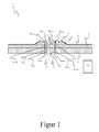
- FIG. 1shows a manufacturing apparatus 1, with which a fiber composite component of a semifinished fiber product 2 is to be produced.
- the semi-finished fiber product 2is introduced from a plurality of layers of fiber material in a mold 3.
- the matrix materialis injected into the semifinished fiber 2, so as to wet the fiber material of the semifinished fiber 2 completely with matrix material.
- a cavity mold 4is arranged on the semifinished fiber 2, which contains the additional cavity 5 required for the method according to the invention.
- the additional cavity 5 of the cavity mold 4is open in the direction of the semifinished fiber product 2 on one side and is thus communicating with the semifinished fiber product 2 so that during the injection process the material injected into the semi-finished fiber material 2 is also injected into the additional cavity 5 of the cavity mold 4 ,
- a vacuum film 6is provided for the complete vacuum build-up, which is intended to close the semifinished fiber product 2 in a vacuum-tight manner relative to the mold 3.
- the cavity mold 4is provided, the vacuum film 6 and the cavity mold 4 sealing the semifinished fiber product 2 in a vacuum-tight manner relative to the mold 3 by means of a seal 7.
- a first sound measuring system 8 and a second sound measuring system 9are now provided, with which sound signals, for example ultrasonic pulses, can be emitted into the semifinished fiber product 2 filled with matrix material and the additional cavity 5 filled with matrix material.
- each of the two sound measuring systems 8 and 9each have a sounder and a sound sensor, so that the principle of operation of the sound transmission application applies.
- the sounderare arranged on the underside of the mold 3, while the sound sensors are arranged on the upper side of the Kavticianstechnikmaschinemaschinemaschinens 4.
- the first sound measuring system 8thus has on the underside of the molding tool 3 a sounder 8 encoders , which emits a sound signal in the direction of arranged on the Kavticianstechnikmaschine 4 sound sensor 8 sensor.
- a first sound measurement section 8 Messis provided, in which a sound signal through the mold 3, through the semi-finished fiber 2 and through the Kavticianstechnikmaschine 4 is turned on until it is received by the sound sensor 8 sensor .
- the running time t 1can then be calculated from the first sound signal.
- the calculation of the sensor precursors SV 11 and SV 12can be done, for example, by determining the transit time with the aid of a reference sound signal, namely, if no semi-finished fiber 2 was placed in the mold 3 and the Kavticianstechnikmaschine 4 coupled directly to the mold 3 coupled by means of a coupling material such as water rests. Based on the duration of the reference sound signal then the sensor flow SV 11 and SV 12 can be determined.
- a second sound measurement section 9 Messis set up with the aid of the second sound measurement system 9, a sounder 9 encoder being arranged on the molding tool 3, while the sound sensor 9 sensor is arranged on the cavity tool 4.
- the second sound measurement section 9 Messis set up such that the sound signal is emitted at least into the semifinished fiber product 2 and into the additional cavity 5 of the cavity mold 4.
- the sound signalis transmitted through the mold 3, then through the semi-finished fiber 2, then through the additional cavity 5 and then through the rest of the Kavticianstechnikmaschinemaschine 4 or fürgeschallt.
- the sensor streams SV 21 and SV 22 regarding the mold 3 and the Kavticianstechnikmaschine 4can be determined in advance with the aid of a reference sound signal, so the net run times of the sound signal to be determined by the semifinished fiber product 2 and the additional cavity 5.
- the route length d 1relates to the thickness of the semifinished fiber product 2 which is composed of several layers of fiber material.
- FIG. 2schematically shows a manufacturing apparatus in which the principle of operation of the echo-pulse method is applied.
- this sensor / receiveris arranged on the Kavticianstechnikmaschine 4 and is reflected at the boundary layer between the fiber blank 2 and mold 3, so that the echo is received by the sensor again. A sensor flow with respect to the mold 3 then does not need to be considered.
- the additional cavity 5should be such that it is filled with resin during the infusion and demolding after hardening is possible by means of drafting.
- the present inventionit is possible to carry out a curing control of the matrix material in the so-called "o-pen-mold" method and at the same time to determine the laminate thickness.
- Thisdoes not require a fixed estimate of the laminate thickness for calculating the speed of sound, wherein the additional cavity can also be designed in the form of a stamp.
- Thisallows the absolute values of sound velocity and laminate thickness to be determined during the entire infusion and curing process.
- FIG. 3schematically shows an embodiment in which the second sound measuring system is included by the first sound measuring system.
- the first sound measuring system and the second sound measuring systemone and the same sounder 8, 9 donors, which is circular.
- the sensor arranged at the other end of the respective sound measurement sectionis annular in the first sound measurement system, so that the sound sensor 9 of the second sound measurement system can be arranged in its middle opening.
- the second sound measurement systemis thus included in the first sound measurement system.
- This embodimenthas the advantage that only a single sound generator is provided for the two sound measurement systems, wherein the sound sensors due to the annular design of the first sound measurement system can be arranged close to each other, so that the first sound measurement section and the second sound measurement section are close to each other.
Landscapes
- Physics & Mathematics (AREA)
- Health & Medical Sciences (AREA)
- Life Sciences & Earth Sciences (AREA)
- Chemical & Material Sciences (AREA)
- Pathology (AREA)
- Analytical Chemistry (AREA)
- Biochemistry (AREA)
- General Health & Medical Sciences (AREA)
- General Physics & Mathematics (AREA)
- Immunology (AREA)
- Medicinal Chemistry (AREA)
- Food Science & Technology (AREA)
- Engineering & Computer Science (AREA)
- Oral & Maxillofacial Surgery (AREA)
- Thermal Sciences (AREA)
- Acoustics & Sound (AREA)
- Casting Or Compression Moulding Of Plastics Or The Like (AREA)
Abstract
Translated fromGermanDescription
Translated fromGermanDie Erfindung betrifft ein Verfahren zur Herstellung eines Faserverbundbauteils, das aus einem mit einem Matrixmaterial infiltrierten Faserhalbzeug durch Aushärtung des Matrixmaterials hergestellt wird. Die Erfindung betrifft ebenso ein Formwerkzeug hierzu.The invention relates to a method for producing a fiber composite component, which is produced from a semifinished product infiltrated with a matrix material by curing the matrix material. The invention also relates to a molding tool for this purpose.
Bauteile aus einem Faserverbundwerkstoff, sogenannte Faserverbundbauteile, sind aus der Luft- und Raumfahrt heute nicht mehr wegzudenken. Aber auch im Automobilbereich und im Bereich der erneuerbaren Energie (z.B. Windkraftanlagen) findet die Verwendung derartiger Werkstoffe immer mehr Zuspruch. Insbesondere kritische Strukturelemente werden aufgrund der hohen gewichtsspezifischen Festigkeit und Steifigkeit bei minimalem Gewicht aus faserverstärkten Kunststoffen gefertigt. Durch die aus der Faserorientierung resultierenden anisotropen Eigenschaften der Faserverbundwerkstoffe können Bauteile exakt an lokale Belastung angepasst werden und ermöglichen so eine optimale Materialausnutzung im Sinne des Leichtbaus.Components made of a fiber composite material, so-called fiber composite components, have become indispensable in the aerospace industry today. But also in the automotive sector and in the field of renewable energy (such as wind turbines), the use of such materials is becoming more and more popular. In particular, critical structural elements are made of fiber reinforced plastics due to the high weight specific strength and stiffness with minimal weight. Due to the anisotropic properties of the fiber composites resulting from the fiber orientation, components can be adapted exactly to local loads and thus enable optimal material utilization in terms of lightweight construction.
Beim herkömmlichen Injektionsverfahren wird bei der Herstellung eines Faserverbundbauteils in trockenes Fasermaterial mit einem Matrixmaterial infiltriert, indem das Matrixmaterial in ein Fasermaterial, das sich in der Regel in einem Formwerkzeug zwecks Formgebung befindet, injiziert wird. Üblicherweise wird das Formwerkzeug zusammen mit dem Faserhalbzeug in einen Autoklaven eingebracht, damit unter Beaufschlagung von Druck und Temperatur das Matrixmaterial in das Fasermaterial des Faserhalbzeuges injiziert werden kann und anschließend das so mit dem Matrixmaterial infiltrierte Faserhalbzeug ausgehärtet werden kann.In the conventional injection method, in the manufacture of a fiber composite component into dry fibrous material, it is infiltrated with a matrix material by injecting the matrix material into a fibrous material which is typically located in a molding tool for molding. Usually, the mold is introduced together with the semifinished fiber product in an autoclave, thus under the application of pressure and temperature, the matrix material can be injected into the fiber material of the semifinished fiber and then the so-infiltrated with the matrix material semifinished fiber can be cured.
Dabei ist es wünschenswert, den Injektions- und Aushärtungsprozess zu überwachen, um so die vorgegebenen Randbedingungen des herzustellenden Faserverbundbauteils prozesssicher einhalten zu können. Dabei stellt sich die Schwierigkeit, dass aufgrund des in sich abgeschlossenen Autoklavprozesses eine Überwachung der maßgeblichen Messgrößen nur bedingt möglich ist.It is desirable to monitor the injection and curing process, so as to be able to reliably comply with the predetermined boundary conditions of the fiber composite component to be produced. This raises the difficulty that due to the self-contained autoclave process monitoring of the relevant parameters is only partially possible.
Es ist bekannt, mit Hilfe von Ultraschall den Aushärtungsprozess von Faserverbundbauteilen während der Aushärtung zu überwachen. Dabei wird von einem Ultraschallwandler bzw. einem Ultraschallgeber ein Ultraschallimpuls durch das Faserhalbzeug gesendet und von einem gegenüberliegenden Empfänger bzw. Sensor detektiert. Anhand der gemessenen Zeit, die der Ultraschallimpuls durch das Faserhalbzeug benötigt, lässt sich die Schallgeschwindigkeit des Matrixmaterials ableiten, die mit zunehmender Vernetzung des Matrixmaterials und somit zunehmendem Fortschritt des Aushärtungsprozesses steigt. Daher lässt sich anhand der Schallgeschwindigkeit des Matrixmaterials sehr gut der Fortschritt des Aushärtungsprozesses feststellen.It is known to monitor the curing process of fiber composite components during curing by means of ultrasound. In this case, an ultrasonic pulse is transmitted through the semi-finished fiber product from an ultrasonic transducer or an ultrasonic transducer and detected by an opposite receiver or sensor. Based on the measured time required by the ultrasonic pulse through the semifinished fiber, the speed of sound of the matrix material can be derived, which increases with increasing crosslinking of the matrix material and thus increasing progress of the curing process. Therefore, the progress of the curing process can be determined very well on the basis of the speed of sound of the matrix material.
Ein Beispiel hierfür ist die
Die Anwendung der Ultraschalltechnik bei der Herstellung von Faserverbundbauteilen zur Ermittlung der Schallgeschwindigkeit ist sinnvoll doch nur dann möglich, wenn zwei starre Formhälften ("closed-mould") eines Formwerkzeuges verwendet werden, da dann eine definierte und konstante Bauteildicke vorgegeben ist, die als Grundlage zur Berechnung der Schallgeschwindigkeit aus den Laufzeiten der Ultraschallimpulse dient. Bei sogenannten "open-mould"-Verfahren, bei denen nur eine starre Formseite vorhanden ist, während die zweite Formseite in der Regel flexibel und durch eine Vakuumfolie abgedeckt ist, ist die konkrete Bauteildicke des Faserverbundbauteils während des Aushärtungsprozesses nicht genau bekannt, da sie großen Schwankungen während des Infusions- und Aushärtungsprozesses unterliegt. Damit ist im Ultraschallmesssystem nicht nachvollziehbar, ob die Laufzeitänderung durch die Vernetzung des Harzes oder einer Dickenänderung hervorgerufen wird. Daher kann auch keine genaue Schallgeschwindigkeit berechnet werden, wodurch keine Aussage über den aktuellen Vernetzungsgrad getroffen werden kann.The application of ultrasonic technology in the production of fiber composite components for the determination of the speed of sound makes sense only then possible if two rigid mold halves ("closed-mold") of a mold are used, since then a defined and constant component thickness is given, which serves as a basis for calculating the speed of sound from the transit times of the ultrasonic pulses. In so-called "open-mold" methods, in which only a rigid mold side is present, while the second mold side is usually flexible and covered by a vacuum film, the concrete component thickness of the fiber composite component during the curing process is not known exactly because they are large Fluctuates during the infusion and curing process. Thus, it is incomprehensible in the ultrasonic measuring system whether the transit time change is caused by the crosslinking of the resin or a change in thickness. Therefore, no exact speed of sound can be calculated, whereby no statement can be made about the current degree of crosslinking.
Bei diesen "open-mould"-Verfahren ist die Bauteildicke, die in der Regel die Messrichtung des Ultraschallimpulses darstellt, aufgrund der Beschaffenheit des Fasermaterials, der Menge des in das Fasermaterial infiltrierten Matrixmaterials und durch den Druck im Autoklaven veränderlich. Mangels Messmethoden zur Bestimmung der Bauteildicke im Prozess kann die Bauteildicke jedoch nur nach Durchlaufen des Infusions- und Aushärtungsprozesses am fertigen Bauteil gemessen werden. Die optimalen Prozessparameter zum Erreichen einer gezielten Bauteildicke muss also in einer aufwendigen Versuchsreihe gefunden werden. Die zahlreichen Einflussparameter auf dem Infusionsprozess und die Bauteildickenentwicklung können dennoch nicht erfasst werden, wodurch auch bei optimierten Prozessparametern eine hohe Bauteildickentoleranz auftritt.In this "open-mold" method, the component thickness, which usually represents the measuring direction of the ultrasonic pulse, is variable due to the nature of the fiber material, the amount of matrix material infiltrated into the fiber material and the pressure in the autoclave. Due to the lack of measurement methods for determining the component thickness in the process, the component thickness can only be measured after passing through the infusion and curing process on the finished component. The optimal process parameters for achieving a targeted component thickness must therefore be found in a complex series of experiments. Nevertheless, the numerous influencing parameters on the infusion process and the component thickness development can not be detected, which results in a high component thickness tolerance even with optimized process parameters.
Es ist Aufgabe der vorliegenden Erfindung ein verbessertes Verfahren und eine verbesserte Vorrichtung zur Herstellung eines Faserverbundbauteils anzugeben, mit dem insbesondere im "open-mould"-Verfahren die physikalischen und chemischen Eigenschaften des Faserverbundbauteils während des Infusions- und Aushärtungsprozesses sicher und exakt überwacht werden können.It is an object of the present invention to provide an improved method and an improved apparatus for producing a fiber composite component, with the particular in the "open-mold" method, the physical and chemical properties of the fiber composite component during the infusion and Curing process can be safely and accurately monitored.
Die Aufgabe wird mit dem Verfahren gemäß Anspruch 1 sowie mit der Fertigungsvorrichtung gemäß Anspruch 7 erfindungsgemäß gelöst.The object is achieved by the method according to
Gemäß Anspruch 1 wird ein Verfahren zur Herstellung eines Faserverbundbauteils vorgeschlagen, bei dem zunächst, wie aus dem Stand der Technik bekannt, die Laufzeit eines ersten Schallsignals einer ersten Schallmessstrecke mittels eines ersten Schallmesssystems ermittelt wird. Hierfür wird das erste Schallsignal in das mit dem Matrixmaterial infiltrierten Faserhalbzeug emittiert. Es ist nicht zwangsläufig notwendig, dass das Faserhalbzeug bereits vollständig mit dem Matrixmaterial infiltriert wurde. Es sollte jedoch der Bereich des Faserhalbzeuges der von der ersten Schallmessstrecke betroffen ist, mit dem Matrixmaterial infiltriert sein.According to
Erfindungsgemäß wird nun vorgeschlagen, dass die Laufzeit eines zweiten Schallsignals einer zweiten Schallmessstrecke mittels eines zweiten Schallmesssystems ermittelt wird. Im Unterschied zu der ersten Schallmessstrecke wird dabei das zweite Schallsignal in das mit dem Matrixmaterial infiltrierten Faserhalbzeug und in eine mit dem Matrixmaterial gefüllte Zusatzkavität, die Bestandteil der zweiten Schallmessstrecke ist, emittiert, so dass das zweite Schallsignal wenigstens durch das mit dem Matrixmaterial infiltrierten Faserhalbzeug und die zusätzlich vorgesehene und mit dem Matrixmaterial gefüllte Zusatzkavität gesendet wird. Mit anderen Worten, das zweite Schallsignal durchläuft sowohl das mit dem Matrixmaterial infiltrierte Faserhalbzeug als auch die mit dem Matrixmaterial gefüllte Zusatzkavität.According to the invention, it is now proposed that the transit time of a second sound signal of a second sound measurement section be determined by means of a second sound measurement system. In contrast to the first sound-measuring section, the second sound signal is emitted into the semifinished fiber product infiltrated with the matrix material and into an additional cavity filled with the matrix material, which is part of the second sound-measuring section, so that the second sound signal is emitted at least through the semi-finished fiber product infiltrated with the matrix material the additionally provided and filled with the matrix material Zusatzkavität is sent. In other words, the second sound signal passes through both the semifinished product infiltrated with the matrix material and the additional cavity filled with the matrix material.
Erfindungswesentlich ist hierbei, dass die mit dem Matrixmaterial gefüllte Zusatzkavität nicht Bestandteil der ersten Schallmessstrecke ist, so dass die Laufzeit des ersten Schallsignals sich aus der Schallmessstrecke ohne die Zusatzkavität ergibt.It is essential to the invention that the additional cavity filled with the matrix material is not part of the first sound measurement section, so that the propagation time of the first sound signal is from the sound measurement section without the additional cavity results.
Aufgrund der Tatsache, dass die Abmessungen der verwendeten Zusatzkavität bekannt sind, lässt sich unter Kenntnis der Laufzeit des ersten Schallsignals, der Laufzeit des zweiten Schallsignals und der Streckenlänge des die Zusatzkavität betreffenden Teils der zweiten Schallmessstrecke die Schallgeschwindigkeit des Matrixmaterials durch eine Auswerteeinheit während des Infusions- und/oder Aushärtungsprozesses berechnen.Due to the fact that the dimensions of the additional cavity used are known, the speed of sound of the matrix material can be determined by an evaluation unit during the infusion, knowing the transit time of the first sound signal, the transit time of the second sound signal and the path length of the part of the second sound measurement section concerning the additional cavity. and / or cure process.
So lässt sich beispielsweise die Schallgeschwindigkeit des Matrixmaterials mittels der folgenden Formel berechnen
, wobei c die Schallgeschwindigkeit ist, Δd2 die Streckenlänge des die Zusatzkavität betreffenden Teils der zweiten Schallmessstrecke ist, t1 die Laufzeit des ersten Schallsignals und t2 die Laufzeit des zweiten Schallsignals darstellen. Vorteilhafterweise handelt es sich bei den Laufzeiten der Schallsignale um die sogenannten Netto-Laufzeiten, d.h. abzüglich eventueller Sensorvorläufe. Die Netto-Laufzeit des ersten Schallsignals betrifft somit nur die Laufzeit des Schallsignals innerhalb des mit dem Matrixmaterial infiltrierten Faserhalbzeuges, während die Netto-Laufzeit des zweiten Schallsignals die Laufzeit des Schallsignals in dem mit Matrixmaterial infiltrierten Faserhalbzeug und die mit Matrixmaterial gefüllte Zusatzkavität betrifft. Die Differenz der Laufzeiten kann alternativ auch aus den beiden gemessenen Signalen bestimmt werden.For example, the speed of sound of the matrix material can be calculated using the following formula
, where c is the speed of sound, Δd2 is the path length of the part of the second sound path that relates to the additional cavity, t1 is the transit time of the first sound signal and t2 is the transit time of the second sound signal. Advantageously, the propagation times of the sound signals are the so-called net run times, ie less any sensor heats. The net transit time of the first sound signal thus relates only to the transit time of the sound signal within the semifinished product infiltrated with the matrix material, while the net transit time of the second sound signal relates to the transit time of the sound signal in the semi-finished fiber material infiltrated with matrix material and the additional cavity filled with matrix material. The difference of the transit times can alternatively also be determined from the two measured signals.
Durch die Anordnung zweier paralleler Schallmessstrecken, wobei eine der beiden Schallmessstrecken eine definierte Zusatzkavität mit Matrixmaterial enthält, kann auf die Laufzeit eines Schallsignals innerhalb der Zusatzkavität bezüglich der vorgegebenen Streckenlänge der Zusatzkavität geschlossen werden, woraufhin sich die Schallgeschwindigkeit des Matrixmaterials nahezu exakt berechnen lässt. Hierdurch lässt sich auch innerhalb der "open-mould"-Verfahren bei der Herstellung von Faserverbundbauteilen anhand der Schallgeschwindigkeit der Fortschritt der Vernetzung des Matrixmaterials während des Aushärtungsprozesses überwachen, so dass der gesamte Infusions- und Aushärtungsprozess online überwachbar wird.By the arrangement of two parallel Schallmessstrecken, where one of the two Sound transmission distances containing a defined additional cavity with matrix material, can be concluded that the transit time of a sound signal within the additional cavity with respect to the predetermined length of the additional cavity, whereupon the speed of sound of the matrix material can be calculated almost exactly. As a result, it is also possible to monitor the progress of the crosslinking of the matrix material during the curing process within the "open-mold" process in the manufacture of fiber composite components on the basis of the speed of sound, so that the entire infusion and curing process can be monitored online.
Vorteilhafterweise liegen die beiden Schallmessstrecken relativ dicht beieinander, um so lokale Unterschiede in der Streckenlänge innerhalb des Faserhalbzeuges zu minimieren. Es ist außerdem besonders vorteilhaft, wenn die Steckenlänge des die Zusatzkavität betreffenden Teils der zweiten Schallmessstrecke kleiner ist als die Streckenlänge des das Faserhalbzeug betreffenden Teils der zweiten Schallmessstrecke.Advantageously, the two Schallmessstrecken are relatively close together, so as to minimize local differences in the route length within the semifinished fiber product. It is also particularly advantageous if the length of the plug of the additional cavity part of the second sound path is smaller than the length of the part of the second semi-conductor measuring section of the semifinished fiber product.
Unter einem Faserhalbzeug im Sinne der vorliegenden Erfindung wird das noch nicht ausgehärtete Faserverbundbauteil verstanden, das zumindest Fasermaterial aufweist. Unter dem Faserhalbzeug wird auch das mit dem Matrixmaterial infiltrierte Fasermaterial in Kombination verstanden. Denkbar hierbei wären auch bereits vorimprägnierte Faserhalbzeuge.In the context of the present invention, a semifinished fiber product is understood to mean the not yet cured fiber composite component which has at least fiber material. The semifinished fiber product also means the fiber material infiltrated with the matrix material in combination. Conceivable here would also be pre-impregnated fiber semi-finished products.
Ein Schallsignal kann beispielsweise ein Ultraschallimpuls sein, der mit Hilfe eines Ultraschallgebers in das Faserhalbzeug emittiert, d.h. ausgesendet wird. Dabei können grundsätzlich die beiden bekannten Schallverfahren eingesetzt werden: Durchschallungsverfahren oder Impuls-Echo-Verfahren. Beim Durchschallungsverfahren wird auf der einen Seite ein Schallgeber angeordnet, der ein Schallsignal in das Faserhalbzeug emittiert, während auf der gegenüberliegenden Seite ein Schallsensor vorgesehen ist, der das emittierte Schallsignal nach dem Durchlaufen des Schallsignals durch das Faserhalbzeug empfängt. Beim Impuls-Echo-Verfahren ist der Schallgeber und Schallsensor identisch, wobei sich hier insbesondere piezoelektrische Schallelemente eignen.A sound signal may, for example, be an ultrasonic pulse which emits with the aid of an ultrasound generator into the semifinished fiber product, ie is emitted. Basically, the two known sound methods can be used: transmission method or pulse-echo method. In the transmission method, a sound generator is arranged on one side, which emits a sound signal in the semifinished fiber, while on the opposite side of a sound sensor is provided which detects the emitted sound signal after passing through the sound signal through the semifinished fiber product receives. In the pulse-echo method, the sounder and the sound sensor are identical, with piezoelectric sound elements being particularly suitable here.
Die Zusatzkavität weist insbesondere in formstabiles Material auf, das sich unter Einwirkung von Druck und Temperatur beispielsweise innerhalb eines Autoklaven, nicht oder nur sehr wenig verformt, unabhängig von der physikalischen Wärmeausdehnung. Hierbei ist es zweckmäßig, dass die Zusatzkavität aus dem gleichen Material wie das Formwerkzeug besteht.The additional cavity has, in particular, a dimensionally stable material which under the action of pressure and temperature, for example within an autoclave, does not deform or only very slightly deforms, independently of the physical thermal expansion. It is expedient that the additional cavity consists of the same material as the mold.
Vorteilhafterweise lässt sich mit Hilfe der Auswerteeinheit auch eine Streckenlänge des das Faserhalbzeug betreffenden Teils der ersten Schallmessstrecke in Abhängigkeit von der Laufzeit des ersten Schallsignals und der berechneten Schallgeschwindigkeit des Matrixmaterials berechnen, so dass sich aufgrund der erfindungsgemäß berechneten Schallgeschwindigkeit des Matrixmaterials die Bauteildicke, die parallel zu den Schallmessstrecken ist, berechnen lässt. Dies kann beispielsweise mit Hilfe der folgenden Formel erfolgen
wobei d1 die Streckenlänge des das Faserhalbzeug betreffenden Teils der ersten Schallmessstrecke ist, c die Schallgeschwindigkeit und t1 die Laufzeit des ersten Schallsignals darstellen.Advantageously, with the aid of the evaluation unit, it is also possible to calculate a length of the part of the first sound measuring section relating to the semifinished product as a function of the propagation time of the first sound signal and the calculated speed of sound of the matrix material, so that due to the inventive calculated speed of sound of the matrix material, the component thickness parallel to is the sound measurement distances, can be calculated. This can be done, for example, using the following
where d1 is the path length of the semifinished part of the relevant part of the first sound transmission path, c represent the speed of sound and t1, the duration of the first sound signal.
Es lässt sich auch die Streckenlänge des das Faserhalbzeug betreffenden Teils der zweiten Schallmessstrecke berechnen, wobei hier die Streckenlänge durch die Zusatzkavität herausgerechnet werden muss. Somit stellt dies ein Äquivalent zu den Berechnungen der Streckenlänge des das Faserhalbzeug betreffenden Teils der ersten Schallmessstrecke dar.It is also possible to calculate the route length of the part of the second sound measurement section concerning the semifinished fiber product, in which case the route length must be calculated out by the additional cavity. Thus, this provides an equivalent to the calculations of the length of the section of the semifinished part of the first sound transmission section.
Unter einer Schallmessstrecke im Sinne der vorliegenden Erfindung wird insbesondere die Haupt-Ausbreitungsrichtung bzw. der Haupt-Ausbreitungsweg zwischen dem Sender und dem Empfänger verstanden. Beim Durchschallungsverfahren bedeutet dies, dass die Schallmessstrecke insbesondere der Weg durch das Faserhalbzeug ist, der sich als gedachte Linie zwischen dem Sender und dem Empfänger ergibt. Beim Impuls-Echo-Verfahren ist die Schallmessstrecke der Weg vom Schallgeber insbesondere durch das Faserhalbzeug bis zu dem reflektierenden Bereich und dann wieder zurück zum Schallgeber, der dann als Sensor fungiert. Die Schallmessstrecke ist somit jener Weg des Schallimpulses, der zwischen Sender und Empfänger liegt. In der Regel ist dies die kürzeste Verbindung.A sound transmission path in the sense of the present invention is understood in particular to mean the main propagation direction or the main propagation path between the transmitter and the receiver. In the case of the through-sounding method, this means that the sound-measuring path is, in particular, the path through the semi-finished fiber product, which results as an imaginary line between the transmitter and the receiver. In the pulse-echo method, the sound-measuring path is the path from the sound generator, in particular through the semifinished fiber product, up to the reflecting area and then back to the sound generator, which then acts as a sensor. The sound path is thus the path of the sound pulse that lies between transmitter and receiver. In general, this is the shortest connection.
Anhand der berechneten Schallgeschwindigkeit und alternativ oder zusätzlich auch anhand der Streckenlänge des das Faserhalbzeug betreffenden Teils der ersten Schallmessstrecke kann dann während des Herstellungsprozesses die Prozessparameter des Herstellungsprozesses durch eine Steuereinheit eingestellt werden. Hierdurch wird es beispielsweise möglich, die Faserhalbzeugdicke auch bei schwankenden Randbedingungen (Flächengewicht des Fasermaterials, Fließeigenschaften des Harzes, Fließfrontverlauf) durch Regelung der Prozessparameter gezielt und reproduzierbar einzustellen. So kann die Faserhalbzeugdicke beispielsweise unter anderem durch Druckänderung im Autoklaven oder durch gezieltes Öffnen und Schließen der Matrixmaterialleitungen gesteuert werden. Darüber hinaus können durch die berechnete Schallgeschwindigkeit Rückschlüsse auf den Aushärtungsgrad des Matrixmaterials geschlossen werden, so dass die eigentliche Autoklav-Zykluszeit exakt an die vorherrschenden Bedingungen angepasst werden kann.On the basis of the calculated speed of sound and, alternatively or additionally, on the basis of the length of the part of the first sound measuring section relating to the semifinished fiber product, the process parameters of the production process can then be set by a control unit during the production process. This makes it possible, for example, to set the semi-finished fiber thickness in a controlled and reproducible manner even under fluctuating boundary conditions (basis weight of the fiber material, flow properties of the resin, flow front course) by regulating the process parameters. Thus, the semi-finished fiber thickness can be controlled, for example, inter alia by pressure change in the autoclave or by selective opening and closing of the matrix material lines. In addition, conclusions about the degree of curing of the matrix material can be drawn from the calculated sound velocity, so that the actual autoclave cycle time can be adapted exactly to the prevailing conditions.
Vorteilhafterweise wird die Zusatzkavität an oder in dem Faserhalbzeug in der zweiten Schallmessstrecke derart angeordnet, dass während der Injektion des Matrixmaterials in das Fasermaterial des Faserhalbzeuges die Zusatzkavität ebenfalls mit dem injizierten Matrixmaterial gefüllt wird. Hierdurch kann sichergestellt werden, dass während des Injektionsvorgangs das in das Fasermaterial des Faserhalbzeuges injizierte Matrixmaterial auch die Zusatzkavität füllt, so dass das vorliegende Verfahren sichere Ergebnisse liefert. Hierfür kann beispielsweise ein Kavitätswerkzeug vorgesehen sein, das die Zusatzkavität enthält und mit der offenen Seite die Zusatzkavität auf das Faserhalbzeug gelegt wird. Während der Injektion des Matrixmaterials kann so das Matrixmaterial aus dem Faserhalbzeug in die Zusatzkavität einfließen und diese somit befüllen.Advantageously, the additional cavity is arranged on or in the semifinished fiber in the second sound transmission path such that during the injection of the matrix material in the fiber material of the semifinished fiber, the additional cavity is also filled with the injected matrix material. This makes it possible to ensure that during the injection process, the matrix material injected into the fiber material of the semifinished fiber product also fills the additional cavity, so that the present method provides reliable results. For this purpose, for example, a Kavitätswerkzeug be provided which contains the additional cavity and the additional cavity is placed on the semi-finished fiber with the open side. During the injection of the matrix material, the matrix material from the semi-finished fiber product can thus flow into the additional cavity and thus fill it.
In weiteren vorteilhaften Ausführungsformen wird für die erste Schallmessstrecke ein erster Sensorvorlauf und für die zweite Schallmessstrecke ein zweiter Sensorvorlauf ermittelt, um so die Netto-Laufzeiten der Schallsignale zu ermitteln. Hierfür wird anhand eines Referenz-Schallsignals die Laufzeit des Schallsignals außerhalb des das Faserhalbzeug betreffenden Teils der ersten Schallmessstrecke berechnet, so dass die Laufzeit des ersten Schallsignals abzüglich des ersten Sensorvorlaufes ermittelbar wird. Die Laufzeit des ersten Schallsignals betrifft dann somit lediglich die Laufzeit des Schallsignals in dem Faserhalbzeug selbst.In further advantageous embodiments, a first sensor flow is determined for the first sound path and a second sensor flow for the second sound path, so as to determine the net transit times of the sound signals. For this purpose, the transit time of the sound signal is calculated outside of the semifinished part of the first part of the first sound transmission path based on a reference sound signal, so that the term of the first sound signal minus the first sensor lead is determined. The duration of the first sound signal then only affects the duration of the sound signal in the semi-finished fiber itself.
Genauso wird auch die Laufzeit des zweiten Schallsignals ermittelt, wobei hierfür ein zweiter Sensorvorlauf der zweiten Schallmessstrecke ermittelt wird, wobei hier jedoch in Abhängigkeit von einem Referenz-Schallsignal die Laufzeit des Schallsignals sowohl außerhalb des das Faserhalbzeug betreffenden Teils der zweiten Schallmessstrecke und außerhalb des die Zusatzkavität betreffenden Teils der zweiten Schallmessstrecke berechnet wird. Die Laufzeit der zweiten Schallmessstrecke wird dann abzüglich dieses zweiten Sensorvorlaufes ermittelt, wobei somit die Laufzeit des zweiten Schallsignals die reine Laufzeit des Schallsignals in dem Faserhalbzeug und in der Zusatzkavität enthält.Similarly, the duration of the second sound signal is determined, for which purpose a second sensor flow of the second sound path is determined, but here depending on a reference sound signal, the duration of the sound signal both outside of the semifinished fiber part of the second sound path and outside of the Zusatzkavität relevant part of the second sound path is calculated. The duration of the second sound transmission path is then determined minus this second sensor flow, whereby the duration of the second sound signal thus the pure duration of the Sound signal in the semifinished fiber product and in the additional cavity contains.
Hierdurch wird es möglich, dass die Schallmesssysteme außen an ein Formwerkzeug angebracht werden können, so dass die Schallgeber und Schallempfänger nicht zwangsläufig direkt mit dem Faserhalbzeug in Kontakt treten müssen. Der Sensorvorlauf betrifft dabei insbesondere die Strecke durch das Formwerkzeug sowie durch das Kavitätswerkzeug der Zusatzkavität, auf der beispielsweise ein Teil des Schallmesssystems angeordnet sein kann.This makes it possible that the sound measurement systems can be attached to the outside of a mold, so that the sounder and sound receiver does not necessarily have to come into direct contact with the semi-finished fiber. In particular, the sensor flow relates to the path through the molding tool and through the cavity tool of the additional cavity, on which, for example, a part of the sound measurement system can be arranged.
Die Erfindung wird anhand der beigefügten Figuren beispielhaft erläutert. Es zeigen:
Figur 1- - Schematische Darstellung einer Fertigungsvorrichtung im Funktionsprinzip des Durchschallungs-Verfahrens;
Figur 2- - Schematische Darstellung einer Fertigungsvorrichtung im Funktionsprinzip des Impuls-Echo-Verfahrens;
Figur 3- - Schematische Darstellung einer Ausführungsform mit ringförmigem Sensor.
- FIG. 1
- - Schematic representation of a manufacturing device in the functional principle of the Durchschallungs-process;
- FIG. 2
- - Schematic representation of a manufacturing device in the functional principle of the pulse-echo method;
- FIG. 3
- - Schematic representation of an embodiment with annular sensor.
Gegenüberliegend des Formwerkzeuges 3 wird auf das Faserhalbzeug 2 ein Kavitätswerkzeug 4 angeordnet, das die für das erfindungsgemäße Verfahren benötigte Zusatzkavität 5 enthält. Die Zusatzkavität 5 des Kavitätswerkzeuges 4 ist dabei in Richtung des Faserhalbzeuges 2 an einer Seite offen und steht somit mit dem Faserhalbzeug 2 kommunizierend in Verbindung, so dass während des Injektionsprozesses das in das Faserhalbzeug 2 injizierte Materixmaterial auch in die Zusatzkavität 5 des Kavitätswerkzeuges 4 injiziert wird. Für den vollständigen Vakuumaufbau ist des Weiteren eine Vakuumfolie 6 vorgesehen, die das Faserhalbzeug 2 gegenüber dem Formwerkzeug 3 vakuumdicht verschließen soll. Im Bereich der Vakuumfolie 6 ist dabei das Kavitätswerkzeug 4 vorgesehen, wobei mittels einer Dichtung 7 die Vakuumfolie 6 und das Kavitätswerkzeug 4 das Faserhalbzeug 2 vakuumdicht gegenüber dem Formwerkzeug 3 abdichtet.Opposite the forming
Mittels eines derartigen Aufbaus lassen sich nun die herkömmlichen Infusionsund Aushärtungsprozesse zur Herstellung eines Faserverbundbauteils durchführen, bei denen zunächst das Faserhalbzeug 2 evakuiert, dann das Matrixmaterial injiziert und anschließend das injizierte Matrixmaterial in dem Faserverbundbauteil ausgehärtet wird. Bei der Injektion des Matrixmaterials in das Faserhalbzeug 2 wird dabei auch die Zusatzkavität 5 des Kavitätswerkzeuges 4 mit dem Matrixmaterial gefüllt.By means of such a construction, it is now possible to carry out the conventional infusion and curing processes for producing a fiber composite component, in which first the
Erfindungsgemäß sind nun ein erstes Schallmesssystem 8 und ein zweites Schallmesssystem 9 vorgesehen, mit denen Schallsignale, beispielsweise Ultraschallimpulse, in das mit Matrixmaterial gefüllte Faserhalbzeug 2 und die mit Matrixmaterial gefüllte Zusatzkavität 5 emittiert werden können. Im Ausführungsbeispiel der
Das erste Schallmesssystem 8 weist somit an der Unterseite des Formwerkzeuges 3 einen Schallgeber 8Geber auf, der ein Schallsignal in Richtung des an dem Kavitätswerkzeug 4 angeordneten Schallsensors 8 Sensor emittiert. Hierdurch wird eine erste Schallmessstrecke 8Mess bereitgestellt, bei der ein Schallsignal durch das Formwerkzeug 3, durch das Faserhalbzeug 2 und durch das Kavitätswerkzeug 4 durchschalt wird, bis es von dem Schallsensor 8Sensor empfangen wird.The first
Unter Berücksichtigung der Sensorvorläufe SV11 und SV12 lässt sich dann von dem ersten Schallsignal die Laufzeit t1 berechnen. Die Berechnung der Sensorvorläufe SV11 und SV12 kann beispielsweise dadurch geschehen, dass mit Hilfe von einem Referenz-Schallsignal die Laufzeit ermittelt wird, und zwar dann, wenn kein Faserhalbzeug 2 in das Formwerkzeug 3 eingelegt wurde und das Kavitätswerkzeug 4 direkt auf dem Formwerkzeug 3 gekoppelt mit Hilfe eines Koppelmaterials wie beispielsweise Wasser aufliegt. Anhand der Laufzeit des Referenz-Schallsignals lässt sich dann der Sensorvorlauf SV11 und SV12 ermitteln.Taking into account the sensor precursors SV11 and SV12 , the running time t1 can then be calculated from the first sound signal. The calculation of the sensor precursors SV11 and SV12 can be done, for example, by determining the transit time with the aid of a reference sound signal, namely, if no
Die Laufzeit t1 des ersten Schallsignals der ersten Schallmessstrecke 8Mess lässt sich dann wie folgt berechnen:
wobei tgesamt die Gesamtlaufzeit zwischen dem Schallgeber und dem Schallsensor ist, SV11 der Sensorvorlauf im Formwerkzeug 3 und SV12 der Sensorvorlauf im Kavitätswerkzeug 4 darstellt.The transit time t1 of the first sound signal of the first
where ttotal is the total running time between the sounder and the sound sensor, SV11, the sensor flow in the
In unmittelbarer Nähe zu der ersten Schallmessstrecke 8Mess wird eine zweite Schallmessstrecke 9Mess mit Hilfe des zweiten Schallmesssystems 9 errichtet, wobei auch hier ein Schallgeber 9 Geber an dem Formwerkzeug 3 angeordnet ist, während der Schallsensor 9 Sensor an dem Kavitätswerkzeug 4 angeordnet ist.In the immediate vicinity of the first
Die zweite Schallmessstrecke 9Mess ist dabei so eingerichtet, dass das Schallsignal zumindest in das Faserhalbzeug 2 und in die Zusatzkavität 5 des Kavitätswerkzeuges 4 emittiert wird. Im vorliegenden Beispiel der
wobei tgesamt die Gesamtlaufzeit des Schallsignals vom Geber zum Sensor ist, SV21 der Sensorvorlauf des Formwerkzeuges 3 und SV22 der Sensorvorlauf des Kavitätswerkzeuges ist.The second
where ttotal is the total running time of the sound signal from the encoder to the sensor, SV21 is the sensor flow of the
Aufgrund der Tatsache, dass die Abmessungen der Zusatzkavität im Vorfeld bekannt sind und keinen Schwankungen unterliegen, kann die Schallgeschwindigkeit gemäß
berechnet werden, wobei Δd2 die bekannte Streckenlänge der Zusatzkavität 5 darstellt, welche den Teil der zweiten Schallmessstrecke 9Mess betrifft.Due to the fact that the dimensions of the additional cavity are known in advance and are not subject to any fluctuations, the speed of sound can vary according to
where Δd2 represents the known path length of the
Hieraus lässt sich dann im Bereich der ersten Schallmessstrecke 8Mess die Streckenlänge d1 des Teils des Faserhalbzeuges 2 ermitteln, der die erste Schallmessstrecke 8Mess betrifft.
Im vorliegenden Fall betrifft die Streckenlänge d1 die Dicke des Faserhalbzeuges 2 das aus mehreren Lagen Fasermaterial aufgebaut ist. Mittels des vorliegenden Verfahrens lässt sich somit während des Infusions- und Aushärtungsprozesses exakt die Streckenlänge d1 im vorliegenden Fall also die Laminatdicke, berechnen und durch Anpassen der Prozessparameter während der Herstellung entsprechend korrigieren, wenn die Laminatdicke vom Soll abweicht. Mit Hilfe der permanent ermittelten Schallgeschwindigkeit kann darüber hinaus der Fortschritt des Aushärtungsprozesses sicher überwacht werden.In the present case, the route length d1 relates to the thickness of the
Die Zusatzkavität 5 sollte so beschaffen sein, dass sie während der Infusion mit Harz gefüllt wird und durch Formschrägen eine Entformung nach der Aushärtung möglich ist.The
Mit der vorliegenden Erfindung wird es möglich, auch bei den sogenannten "o-pen-mould"-Verfahren eine Aushärtungskontrolle des Matrixmaterials durchzuführen und gleichzeitig die Laminatdicke zu bestimmen. Hierfür bedarf es keines fixen Schätzwertes der Laminatdicke für die Berechnung der Schallgeschwindigkeit, wobei die Zusatzkavität auch in Form eines Stempels ausgeführt sein kann. Damit lassen sich die Absolutwerte von Schallgeschwindigkeit und Laminatdicke während des gesamten Infusions- und Aushärtungsprozesses ermitteln.With the present invention, it is possible to carry out a curing control of the matrix material in the so-called "o-pen-mold" method and at the same time to determine the laminate thickness. This does not require a fixed estimate of the laminate thickness for calculating the speed of sound, wherein the additional cavity can also be designed in the form of a stamp. This allows the absolute values of sound velocity and laminate thickness to be determined during the entire infusion and curing process.
Diese Ausführungsform hat den Vorteil, dass für die beiden Schallmesssysteme nur ein einziger Schallgeber vorgesehen ist, wobei die Schallsensoren aufgrund der ringförmigen Ausbildung des ersten Schallmesssystems dicht beieinander angeordnet werden können, so dass die erste Schallmessstrecke und die zweite Schallmessstrecke dicht beieinander liegen.This embodiment has the advantage that only a single sound generator is provided for the two sound measurement systems, wherein the sound sensors due to the annular design of the first sound measurement system can be arranged close to each other, so that the first sound measurement section and the second sound measurement section are close to each other.
- 11
- - Fertigungsvorrichtung- Manufacturing device
- 22
- - Faserhalbzeug- semi-finished fiber products
- 33
- - Formwerkzeug- mold
- 44
- - Kavitätswerkzeug- Cavity tool
- 55
- - Zusatzkavität- Additional cavity
- 66
- - Vakuumfolie- vacuum film
- 77
- - Dichtung- Poetry
- 88th
- - erstes Schallmesssystem- first sound measuring system
- 8Geber8donors
- - Schallgeber des ersten Schallmesssystems- Sounder of the first sound measurement system
- 8Sensor8sensor
- - Sensor des ersten Schallmesssystems- Sensor of the first sound measurement system
- 8Mess8meas
- - erste Schallmessstrecke- first sound measuring section
- 99
- - zweites Schallmesssystem- second sound measuring system
- 9Geber9donors
- - Schallgeber des zweiten Schallmesssystems- Sounder of the second sound measurement system
- 9Sensor9sensor
- - Schallsensor des zweiten Schallmesssystems- Sound sensor of the second sound measurement system
- 9Mess9meas
- - zweite Schallmessstrecke- second sound measurement section
- t1t1
- - Laufzeit des ersten Schallsignals- Duration of the first sound signal
- d1d1
- - Streckenlänge des das Faserhalbzeug betreffenden Teils der ersten Schallmessstrecke- Length of the semifinished part of the part of the first sound transmission path
- SV11, SV12SV11 , SV12
- - Sensorvorlauf der ersten Schallmessstrecke- Sensor flow of the first sound path
- t2t2
- - Laufzeit des zweiten Schallsignals- Duration of the second sound signal
- d2d2
- - Streckenlänge des das Faserhalbzeug und die Zusatzkavität betreffenden Teils der zweiten Schallmessstrecke- Length of the fiber semifinished product and the additional cavity part of the second sound transmission section
- SV21, SV22SV21 , SV22
- - Sensorvorlauf der zweiten Schallmessstrecke- Sensor flow of the second sound path
- Δd2Δd2
- - bekannte Streckenlänge des die Zusatzkavität betreffenden Teils der zweiten Schallmessstrecke.- Known route length of the additional cavity part of the second sound section.
- Ai/auAi / au
Claims (12)
Translated fromGermangekennzeichnet durch
marked by
Applications Claiming Priority (1)
| Application Number | Priority Date | Filing Date | Title |
|---|---|---|---|
| DE102013113063.1ADE102013113063B4 (en) | 2013-11-26 | 2013-11-26 | Process for producing a fiber composite component |
Publications (1)
| Publication Number | Publication Date |
|---|---|
| EP2876436A1true EP2876436A1 (en) | 2015-05-27 |
Family
ID=51999263
Family Applications (1)
| Application Number | Title | Priority Date | Filing Date |
|---|---|---|---|
| EP14194707.7AWithdrawnEP2876436A1 (en) | 2013-11-26 | 2014-11-25 | Method for manufacturing a fibre compound component |
Country Status (2)
| Country | Link |
|---|---|
| EP (1) | EP2876436A1 (en) |
| DE (1) | DE102013113063B4 (en) |
Families Citing this family (1)
| Publication number | Priority date | Publication date | Assignee | Title |
|---|---|---|---|---|
| DE202019101206U1 (en)* | 2019-03-04 | 2020-06-05 | Deutsches Zentrum für Luft- und Raumfahrt e.V. | Device for monitoring a manufacturing process for manufacturing a fiber composite component |
Citations (2)
| Publication number | Priority date | Publication date | Assignee | Title |
|---|---|---|---|---|
| DE19737276A1 (en) | 1997-08-27 | 1999-03-11 | Joachim Dr Doering | Ultrasonic monitoring of duroplastic hardening for control purposes |
| US20080315462A1 (en)* | 2007-06-25 | 2008-12-25 | General Electric Company | Systems and methods for monitoring a composite cure cycle |
Family Cites Families (2)
| Publication number | Priority date | Publication date | Assignee | Title |
|---|---|---|---|---|
| DE10146323B4 (en)* | 2001-09-20 | 2005-07-28 | Institut Für Verbundwerkstoffe Gmbh | Method for the computer-controlled determination of flow data of a flow front and apparatus therefor |
| DE102010037849B4 (en)* | 2010-09-29 | 2015-04-16 | Deutsches Zentrum für Luft- und Raumfahrt e.V. | Method and device for producing fiber composite components in the infusion method |
- 2013
- 2013-11-26DEDE102013113063.1Apatent/DE102013113063B4/ennot_activeExpired - Fee Related
- 2014
- 2014-11-25EPEP14194707.7Apatent/EP2876436A1/ennot_activeWithdrawn
Patent Citations (2)
| Publication number | Priority date | Publication date | Assignee | Title |
|---|---|---|---|---|
| DE19737276A1 (en) | 1997-08-27 | 1999-03-11 | Joachim Dr Doering | Ultrasonic monitoring of duroplastic hardening for control purposes |
| US20080315462A1 (en)* | 2007-06-25 | 2008-12-25 | General Electric Company | Systems and methods for monitoring a composite cure cycle |
Non-Patent Citations (3)
| Title |
|---|
| NICO LIEBERS: "DGZfP-Jahrestagung 2014 - In-Situ Laminatdickenmessung während der Infusion und Aushärtung von Faserverbundkunststoffen", THE E-JOURNAL OF NONDESTRUCTIVE TESTING, 1 March 2015 (2015-03-01), pages 1 - 11, XP055177492, Retrieved from the Internet <URL:http://www.ndt.net/search/link.php?id=17358&file=article/dgzfp2014/papers/mo3a3.pdf> [retrieved on 20150318]* |
| SCHMACHTENBERG E ET AL: "Application of ultrasonics for the process control of Resin Transfer Moulding (RTM)", POLYMER TESTING, ELSEVIER, AMSTERDAM, NL, vol. 24, no. 3, 1 May 2005 (2005-05-01), pages 330 - 338, XP027767365, ISSN: 0142-9418, [retrieved on 20050501]* |
| STOVEN T ET AL: "Continuous monitoring of three-dimensional resin flow through a fibre preform", COMPOSITES PART A: APPLIED SCIENCE AND MANUFACTURING, ELSEVIER SCIENCE PUBLISHERS B.V., AMSTERDAM, NL, vol. 34, no. 6, 1 June 2003 (2003-06-01), pages 475 - 480, XP004428273, ISSN: 1359-835X, DOI: 10.1016/S1359-835X(03)00059-9* |
Also Published As
| Publication number | Publication date |
|---|---|
| DE102013113063B4 (en) | 2015-11-19 |
| DE102013113063A1 (en) | 2015-05-28 |
Similar Documents
| Publication | Publication Date | Title |
|---|---|---|
| DE102010037849B4 (en) | Method and device for producing fiber composite components in the infusion method | |
| DE102010035958B4 (en) | Device and method for producing a component and aircraft structural component | |
| WO2010136350A1 (en) | Apparatus for determining the properties of a medium in the form of a fluid or a soft material | |
| EP2657801A2 (en) | Monitoring of a manufacturing process | |
| DE102016102477B4 (en) | Method for producing a fiber composite component | |
| EP3266597B1 (en) | Method for producing a fibre reinforced composite element | |
| DE102013113063B4 (en) | Process for producing a fiber composite component | |
| DE102013100092A1 (en) | Method for testing impregnation of carbon fiber reinforced plastic composite material during manufacturing material, involves testing degree of impregnation of fibers using arrangement of ultrasound transmitters and ultrasound receivers | |
| DE102017208870B3 (en) | Method and device for producing a fiber-reinforced plastic component | |
| DE102013108568B4 (en) | Determination of the component thickness of a fiber composite component | |
| AT521579B1 (en) | Method for detecting inhomogeneities in melts | |
| DE102016112263B4 (en) | Method and device for producing a fiber composite component | |
| DE102014108639A1 (en) | deformation analysis | |
| DE102020105779A1 (en) | Device for monitoring a manufacturing process for manufacturing a fiber composite component | |
| WO2019043227A1 (en) | METHOD AND DEVICE FOR DETECTING A LEAKAGE | |
| DE102014119381A1 (en) | Method and device for producing a fiber composite component | |
| DE102017213323A1 (en) | Joining device and method for joining components | |
| DE102016214506A1 (en) | Method for connecting at least two components, anvil, punch riveting device and manufacturing device | |
| DE102015122376B4 (en) | Method for producing a fiber composite component | |
| AT520658B1 (en) | PROCESS MONITORING IN THE MANUFACTURING OF INJECTION MOLDED PARTS | |
| DE102015108338A1 (en) | Method and device for producing a fiber composite component | |
| DE102019128530A1 (en) | Method and device for determining a component thickness | |
| AT523420B1 (en) | NON-INVASIVE PRESSURE MEASUREMENT | |
| DE3236036C2 (en) | Method for ultrasonic measurement of the wall thickness of plastic hollow bodies | |
| EP2706343A2 (en) | Method and device for the synchronous determination of the rheological and acoustic properties |
Legal Events
| Date | Code | Title | Description |
|---|---|---|---|
| PUAI | Public reference made under article 153(3) epc to a published international application that has entered the european phase | Free format text:ORIGINAL CODE: 0009012 | |
| 17P | Request for examination filed | Effective date:20141125 | |
| AK | Designated contracting states | Kind code of ref document:A1 Designated state(s):AL AT BE BG CH CY CZ DE DK EE ES FI FR GB GR HR HU IE IS IT LI LT LU LV MC MK MT NL NO PL PT RO RS SE SI SK SM TR | |
| AX | Request for extension of the european patent | Extension state:BA ME | |
| R17P | Request for examination filed (corrected) | Effective date:20151120 | |
| RBV | Designated contracting states (corrected) | Designated state(s):AL AT BE BG CH CY CZ DE DK EE ES FI FR GB GR HR HU IE IS IT LI LT LU LV MC MK MT NL NO PL PT RO RS SE SI SK SM TR | |
| GRAP | Despatch of communication of intention to grant a patent | Free format text:ORIGINAL CODE: EPIDOSNIGR1 | |
| STAA | Information on the status of an ep patent application or granted ep patent | Free format text:STATUS: GRANT OF PATENT IS INTENDED | |
| INTG | Intention to grant announced | Effective date:20190227 | |
| STAA | Information on the status of an ep patent application or granted ep patent | Free format text:STATUS: THE APPLICATION IS DEEMED TO BE WITHDRAWN | |
| 18D | Application deemed to be withdrawn | Effective date:20190710 |