EP2875897B1 - Method of and device for controlling an irradiation system for producing a three-dimensional workpiece - Google Patents
Method of and device for controlling an irradiation system for producing a three-dimensional workpieceDownload PDFInfo
- Publication number
- EP2875897B1 EP2875897B1EP13193905.0AEP13193905AEP2875897B1EP 2875897 B1EP2875897 B1EP 2875897B1EP 13193905 AEP13193905 AEP 13193905AEP 2875897 B1EP2875897 B1EP 2875897B1
- Authority
- EP
- European Patent Office
- Prior art keywords
- irradiation
- contour
- radiation pattern
- section
- area
- Prior art date
- Legal status (The legal status is an assumption and is not a legal conclusion. Google has not performed a legal analysis and makes no representation as to the accuracy of the status listed.)
- Active
Links
Images


Classifications
- B—PERFORMING OPERATIONS; TRANSPORTING
- B23—MACHINE TOOLS; METAL-WORKING NOT OTHERWISE PROVIDED FOR
- B23K—SOLDERING OR UNSOLDERING; WELDING; CLADDING OR PLATING BY SOLDERING OR WELDING; CUTTING BY APPLYING HEAT LOCALLY, e.g. FLAME CUTTING; WORKING BY LASER BEAM
- B23K26/00—Working by laser beam, e.g. welding, cutting or boring
- B23K26/02—Positioning or observing the workpiece, e.g. with respect to the point of impact; Aligning, aiming or focusing the laser beam
- B23K26/06—Shaping the laser beam, e.g. by masks or multi-focusing
- B23K26/0604—Shaping the laser beam, e.g. by masks or multi-focusing by a combination of beams
- B—PERFORMING OPERATIONS; TRANSPORTING
- B22—CASTING; POWDER METALLURGY
- B22F—WORKING METALLIC POWDER; MANUFACTURE OF ARTICLES FROM METALLIC POWDER; MAKING METALLIC POWDER; APPARATUS OR DEVICES SPECIALLY ADAPTED FOR METALLIC POWDER
- B22F10/00—Additive manufacturing of workpieces or articles from metallic powder
- B22F10/30—Process control
- B22F10/31—Calibration of process steps or apparatus settings, e.g. before or during manufacturing
- B—PERFORMING OPERATIONS; TRANSPORTING
- B23—MACHINE TOOLS; METAL-WORKING NOT OTHERWISE PROVIDED FOR
- B23K—SOLDERING OR UNSOLDERING; WELDING; CLADDING OR PLATING BY SOLDERING OR WELDING; CUTTING BY APPLYING HEAT LOCALLY, e.g. FLAME CUTTING; WORKING BY LASER BEAM
- B23K26/00—Working by laser beam, e.g. welding, cutting or boring
- B23K26/34—Laser welding for purposes other than joining
- B23K26/342—Build-up welding
- B—PERFORMING OPERATIONS; TRANSPORTING
- B29—WORKING OF PLASTICS; WORKING OF SUBSTANCES IN A PLASTIC STATE IN GENERAL
- B29C—SHAPING OR JOINING OF PLASTICS; SHAPING OF MATERIAL IN A PLASTIC STATE, NOT OTHERWISE PROVIDED FOR; AFTER-TREATMENT OF THE SHAPED PRODUCTS, e.g. REPAIRING
- B29C64/00—Additive manufacturing, i.e. manufacturing of three-dimensional [3D] objects by additive deposition, additive agglomeration or additive layering, e.g. by 3D printing, stereolithography or selective laser sintering
- B29C64/30—Auxiliary operations or equipment
- B29C64/386—Data acquisition or data processing for additive manufacturing
- B29C64/393—Data acquisition or data processing for additive manufacturing for controlling or regulating additive manufacturing processes
- B—PERFORMING OPERATIONS; TRANSPORTING
- B33—ADDITIVE MANUFACTURING TECHNOLOGY
- B33Y—ADDITIVE MANUFACTURING, i.e. MANUFACTURING OF THREE-DIMENSIONAL [3-D] OBJECTS BY ADDITIVE DEPOSITION, ADDITIVE AGGLOMERATION OR ADDITIVE LAYERING, e.g. BY 3-D PRINTING, STEREOLITHOGRAPHY OR SELECTIVE LASER SINTERING
- B33Y50/00—Data acquisition or data processing for additive manufacturing
- B33Y50/02—Data acquisition or data processing for additive manufacturing for controlling or regulating additive manufacturing processes
- G—PHYSICS
- G05—CONTROLLING; REGULATING
- G05B—CONTROL OR REGULATING SYSTEMS IN GENERAL; FUNCTIONAL ELEMENTS OF SUCH SYSTEMS; MONITORING OR TESTING ARRANGEMENTS FOR SUCH SYSTEMS OR ELEMENTS
- G05B15/00—Systems controlled by a computer
- G05B15/02—Systems controlled by a computer electric
- B—PERFORMING OPERATIONS; TRANSPORTING
- B22—CASTING; POWDER METALLURGY
- B22F—WORKING METALLIC POWDER; MANUFACTURE OF ARTICLES FROM METALLIC POWDER; MAKING METALLIC POWDER; APPARATUS OR DEVICES SPECIALLY ADAPTED FOR METALLIC POWDER
- B22F10/00—Additive manufacturing of workpieces or articles from metallic powder
- B22F10/20—Direct sintering or melting
- B22F10/28—Powder bed fusion, e.g. selective laser melting [SLM] or electron beam melting [EBM]
- B—PERFORMING OPERATIONS; TRANSPORTING
- B22—CASTING; POWDER METALLURGY
- B22F—WORKING METALLIC POWDER; MANUFACTURE OF ARTICLES FROM METALLIC POWDER; MAKING METALLIC POWDER; APPARATUS OR DEVICES SPECIALLY ADAPTED FOR METALLIC POWDER
- B22F10/00—Additive manufacturing of workpieces or articles from metallic powder
- B22F10/30—Process control
- B22F10/32—Process control of the atmosphere, e.g. composition or pressure in a building chamber
- B—PERFORMING OPERATIONS; TRANSPORTING
- B22—CASTING; POWDER METALLURGY
- B22F—WORKING METALLIC POWDER; MANUFACTURE OF ARTICLES FROM METALLIC POWDER; MAKING METALLIC POWDER; APPARATUS OR DEVICES SPECIALLY ADAPTED FOR METALLIC POWDER
- B22F12/00—Apparatus or devices specially adapted for additive manufacturing; Auxiliary means for additive manufacturing; Combinations of additive manufacturing apparatus or devices with other processing apparatus or devices
- B22F12/40—Radiation means
- B22F12/44—Radiation means characterised by the configuration of the radiation means
- B—PERFORMING OPERATIONS; TRANSPORTING
- B22—CASTING; POWDER METALLURGY
- B22F—WORKING METALLIC POWDER; MANUFACTURE OF ARTICLES FROM METALLIC POWDER; MAKING METALLIC POWDER; APPARATUS OR DEVICES SPECIALLY ADAPTED FOR METALLIC POWDER
- B22F12/00—Apparatus or devices specially adapted for additive manufacturing; Auxiliary means for additive manufacturing; Combinations of additive manufacturing apparatus or devices with other processing apparatus or devices
- B22F12/40—Radiation means
- B22F12/49—Scanners
- B—PERFORMING OPERATIONS; TRANSPORTING
- B29—WORKING OF PLASTICS; WORKING OF SUBSTANCES IN A PLASTIC STATE IN GENERAL
- B29C—SHAPING OR JOINING OF PLASTICS; SHAPING OF MATERIAL IN A PLASTIC STATE, NOT OTHERWISE PROVIDED FOR; AFTER-TREATMENT OF THE SHAPED PRODUCTS, e.g. REPAIRING
- B29C64/00—Additive manufacturing, i.e. manufacturing of three-dimensional [3D] objects by additive deposition, additive agglomeration or additive layering, e.g. by 3D printing, stereolithography or selective laser sintering
- B29C64/10—Processes of additive manufacturing
- B29C64/141—Processes of additive manufacturing using only solid materials
- B29C64/153—Processes of additive manufacturing using only solid materials using layers of powder being selectively joined, e.g. by selective laser sintering or melting
- Y—GENERAL TAGGING OF NEW TECHNOLOGICAL DEVELOPMENTS; GENERAL TAGGING OF CROSS-SECTIONAL TECHNOLOGIES SPANNING OVER SEVERAL SECTIONS OF THE IPC; TECHNICAL SUBJECTS COVERED BY FORMER USPC CROSS-REFERENCE ART COLLECTIONS [XRACs] AND DIGESTS
- Y02—TECHNOLOGIES OR APPLICATIONS FOR MITIGATION OR ADAPTATION AGAINST CLIMATE CHANGE
- Y02P—CLIMATE CHANGE MITIGATION TECHNOLOGIES IN THE PRODUCTION OR PROCESSING OF GOODS
- Y02P10/00—Technologies related to metal processing
- Y02P10/25—Process efficiency
Definitions
- the present inventionrelates to a method of and a device for controlling an irradiation system for use in an apparatus for producing a three-dimensional work piece by irradiating layers of a raw material powder with electromagnetic or particle radiation.
- Selective laser melting or laser sinteringis an additive layering process by which pulverulent, in particular metallic and/or ceramic raw materials can be processed to three-dimensional work pieces of complex shapes.
- a raw material powder layeris applied onto a carrier and subjected to laser radiation in a site selective manner in dependence on the desired geometry of the work piece that is to be produced.
- the laser radiation penetrating into the powder layercauses heating and consequently melting or sintering of the raw material powder particles.
- Further raw material powder layersare then applied successively to the layer on the carrier that has already been subjected to laser treatment, until the work piece has the desired shape and size.
- Selective laser melting or laser sinteringcan be used in particular for the production of prototypes, tools, replacement parts or medical prostheses, such as, for example, dental or orthopaedic prostheses, on the basis of CAD data.
- the prior art apparatuscomprises a process chamber which accommodates a plurality of carriers for the shaped bodies to be manufactured.
- a powder layer preparation systemcomprises a powder reservoir holder that can be moved to and fro across the carriers in order to apply a raw material powder onto the carriers.
- the raw material powder applied onto the carriersis irradiated with a laser beam emitted by an irradiation system.
- an irradiation system employed in an apparatus for producing a three-dimensional work piece by selectively irradiating layers of a raw material powder with electromagnetic or particle radiationmay be controlled such that a radiation beam emitted by the irradiation system is guided over a raw material powder layer according to a radiation pattern.
- the radiation patterncontains a plurality of scan vectors which, in at least a section of the radiation pattern, extend substantially parallel to each other.
- the radiation patternmay comprise a plurality of sections, wherein, in each section, the scan vectors may extend substantially parallel to each other, but inclined relative to the scan vectors in an adjacent section of the radiation pattern.
- the sections of the radiation patternmay define a chessboard pattern, a stripe pattern comprising a plurality of substantially parallel stripes or a pattern comprising arbitrarily shaped sections.
- the raw material powdermay be irradiated with electromagnetic or particle radiation by means of an irradiation system comprising a plurality of irradiation units, wherein each irradiation unit may be associated with an irradiation area defined on a surface of a carrier onto which the raw material powder to be irradiated is applied.
- Each irradiation unit of the irradiation systemis controlled such that the raw material powder applied onto the irradiation area associated with the irradiation unit is irradiated in a site selective manner and independent of the irradiation of other irradiation areas not associated with the irradiation unit in question.
- each irradiation area defined on the carriermay be individually and independently irradiated using a desired irradiation pattern.
- at least one overlap areamay be defined on the surface of the carrier.
- Raw material powder applied onto the overlap areacan be selectively irradiated with electromagnetic or particle radiation by at least two irradiation units of the irradiation system. Areas of a large three-dimensional work piece to be built-up on the carrier, which are disposed in adjoining regions of adjacent irradiation areas, thus may be generated with the desired reliability and high quality.
- Document US 2013/0112672 A1on which the preamble of claims 1 and 9 is based relates to a laser configuration for an additive manufacturing machine and process for improving coverage area and for increasing possible overall part area and volume.
- a workspaceis divided into a plurality of regions with overlapping regions disposed between adjacent ones of the regions.
- An example additive manufacturing systemincludes a plurality of energy directing devices that direct laser beams within a corresponding one of the regions within the workspace. Each of the laser beams is directed into a corresponding overlapping area, wherein the overlapping areas include a portion of area within adjacent regions.
- the inventionis directed at the object of providing a method and a device, which allow an irradiation system for use in an apparatus for producing a three-dimensional work piece by irradiating layers of a raw material powder with electromagnetic or particle radiation and comprising a plurality of irradiation units to be controlled in such a manner that a high-quality three-dimensional work piece can be produced.
- a first and a second irradiation area as well as an overlap area arranged between the first and the second irradiation areaare defined on a surface of a carrier adapted to receive a layer of raw material powder.
- the carriermay be disposed in a process chamber of the apparatus for producing a three-dimensional work piece and may be a rigidly fixed carrier.
- the carrieris designed to be displaceable in vertical direction so that, with increasing construction height of a work piece, as it is built up in layers from the raw material powder, the carrier can be moved downwards in the vertical direction.
- the process chambermay be sealable against the ambient atmosphere, i.e. against the environment surrounding the process chamber, in order to be able to maintain a controlled atmosphere, in particular an inert atmosphere within the process chamber.
- the raw material powder to be received on the carrierpreferably is a metallic powder, in particular a metal alloy powder, but may also be a ceramic powder or a powder containing different materials.
- the powdermay have any suitable particle size or particle size distribution. It is, however, preferable to process powders of particle sizes ⁇ 100 ⁇ m.
- the irradiation system to be controlledserves to selectively irradiate the raw material powder applied onto the carrier with electromagnetic or particle radiation.
- the raw material powder applied onto the carriermay be subjected to electromagnetic or particle radiation in a site-selective manner in dependence on the desired geometry of the work piece that is to be produced.
- the irradiation systempreferably is adapted to irradiate radiation onto the raw material powder which causes a site-selective melting of the raw material powder particles.
- Each irradiation unit of the irradiation systemmay comprise a radiation beam source, in particular a laser beam source. It is, however, also conceivable that plural irradiation units are associated with a single radiation beam source, wherein a radiation beam provided by the single radiation beam source, by suitable means such as, for example, beam splitters and/or mirrors, may be split and/or deflected as required so as to direct the radiation beam provided by the radiation beam source to the associated irradiation units. Further, each irradiation unit may comprise at least one optical unit for guiding and/or processing a radiation beam emitted by the radiation beam source and supplied to the irradiation unit.
- the optical unitmay comprise optical elements such as an object lens, in particular an f-theta lens, and a scanner unit, the scanner unit preferably comprising a diffractive optical element and a deflection mirror.
- Each irradiation area defined on the surface of the carrieri.e. the raw material powder applied thereon, may be selectively irradiated with electromagnetic or particle radiation by a selected one of the irradiation units of the irradiation system independent from the other irradiation units of the irradiation system.
- each irradiation area defined on the carriermay be individually and independently irradiated using a desired irradiation pattern. For example, if desired, a small sized three-dimensional work piece may be built-up in only one irradiation area by selectively irradiating the irradiation area with electromagnetic or particle radiation.
- the plurality of irradiation areas defined on the carrierare simultaneously irradiated with electromagnetic or particle radiation by suitable controlling the irradiation units of the irradiation system, thus allowing a large three-dimensional work piece to be built-up in an additive layer construction process within a relatively short time and thus at reasonable costs.
- a first irradiation unit of the irradiation systemis assigned to the first irradiation area and the overlap area. Further, a second irradiation unit of the irradiation system is assigned to the second irradiation area and the overlap area.
- the first irradiation areathen may be selectively irradiated with electromagnetic or particle radiation provided by the first irradiation unit, whereas the second irradiation area may be selectively irradiated with electromagnetic or particle radiation provided by the second irradiation unit.
- the overlap area arranged between the first and the second irradiation areamay be irradiated with electromagnetic or particle radiation provided by either the first or the second irradiation unit.
- electromagnetic or particle radiationprovided by either the first or the second irradiation unit.
- portions of a large three-dimensional work piece to be built-up on the carrier, which are disposed in an adjoining region of the first and the second irradiation areamay be generated with the desired reliability and high quality.
- the first and the second irradiation unitmust be suitably controlled in order to ensure that a three-dimensional work piece extending over more than one irradiation area is built-up with the desired consistency and thus quality.
- the method of controlling an irradiation systemtherefore involves an analysis of a radiation pattern according to which radiation beams emitted by the irradiation units of the irradiation system are guided over the layer of raw material powder received on the carrier or the already produced layers of the work piece and/or a contour of the three-dimensional work piece to be produced and in particular an analysis of the arrangement of the radiation pattern and/or the contour relative to the irradiation areas and the overlap area defined on the surface of the carrier.
- the radiation patternmay be any suitable radiation pattern, for example a chessboard pattern, a stripe pattern or a pattern comprising arbitrarily shaped sections, wherein the individual sections of the radiation pattern may be defined by a plurality of scan vectors.
- the scan vectorsin a section of the radiation pattern, may extend substantially parallel to each other, but may be inclined relative to the scan vectors in an adjacent section of the radiation pattern.
- the scan vectorsmay follow straight lines or curved lines.
- Radiation patterns according to which radiation beams emitted by the irradiation units of the irradiation system are guided over subsequent layers of raw material powdermay be rotated relative to each other. By rotating the radiation patterns upon irradiating subsequent layers of raw material powder, excessive shrinkage and residual stresses in the generated work pieces may be minimized.
- the contour of the three-dimensional work piece to be producedmay be a substantially line-shaped inner or outer contour of the three-dimensional work piece to be produced and may be defined by a plurality of individual scan points.
- a determination stepis performed so as to determine whether a section of the radiation pattern according to which radiation beams emitted by the irradiation units of the irradiation system are guided over the layer of raw material powder received on the carrier and/or a contour of the three-dimensional work piece to be produced extend(s) into the first and the second irradiation area defined on the surface of the carrier.
- the arrangement of the radiation pattern and the contour relative to the irradiation areas and the overlap area defined on the surface of the carrieris analyzed so as to determine whether a section of the radiation pattern and/or the contour extend(s) into more than one irradiation area exclusively associated with only one irradiation unit.
- a section of the radiation pattern and/or a contour of the three-dimensional work piece to be producedextend(s) into the first and the second irradiation area defined on the surface of the carrier, said section of the radiation pattern and/or said contour is split into a first portion and a second portion.
- said section of the radiation pattern and/or said contouris split in a splitting region of the section of the radiation pattern and/or the contour which is located in the overlap area arranged between the first and the second irradiation area.
- the first portion of said section of the radiation pattern and/or said contouris assigned to the first irradiation unit, whereas the second portion of said section of the radiation pattern and/or said contour is assigned to the second irradiation unit.
- the first portion of the section of the radiation pattern and/or the contouris defined by irradiating electromagnetic or particle radiation onto the raw material powder received on the carrier which is provided by the first irradiation unit assigned to the first irradiation area.
- the second portion of the section of the radiation pattern and/or the contouris defined by irradiating electromagnetic or particle radiation onto the raw material powder received on the carrier which is provided by the second irradiation unit assigned to the second irradiation area.
- the control of the irradiation unitscan be simplified and mutual interferences between the radiation beams emitted by the first and the second irradiation unit can be omitted. Consequently, a high-quality three-dimensional work piece can be produced.
- a section of the radiation pattern and/or a contour which in its entirety is located in the overlap areais not split, but assigned to either the first or the second irradiation unit and consequently defined by irradiating electromagnetic or particle radiation onto the raw material powder received on the carrier which is provided by either the first or the second irradiation unit.
- the section of the radiation pattern and/or the contour which in its entirety is located in the overlap area arranged between the first and the second irradiation areamay be assigned to the first irradiation unit, if a predefined element of the section of the radiation pattern and/or the contour is located in a region of the overlap area closer to the first irradiation area.
- the section of the radiation pattern and/or the contour which in its entirety is located in the overlap area arranged between the first and the second irradiation areamay be assigned to the second irradiation unit if a predefined element of the section of the radiation pattern and/or the contour is located in a region of the overlap area closer to the second irradiation area.
- the predefined element of the section of the radiation pattern and/or the contourmay, for example, be a center point or a central region of the section of the radiation pattern and/or the contour.
- the overlap areais divided into a plurality of partitioning regions as will be described in more detail below, it is also conceivable to analyze the position of the predefined element relative to a center line of a selected partitioning region of the overlap area.
- Sections of the radiation pattern and/or contours which extend into the overlap area and only one of the first and the second irradiation areamay be treated similar to sections of the radiation pattern and/or contours which in their entirety are located in the overlap area, i.e. these sections of the radiation pattern and/or contours may be assigned to either the first or the second irradiation unit and hence defined by irradiating electromagnetic or particle radiation onto the raw material powder received on the carrier which is provided by either the first or the second irradiation unit.
- a section of the radiation pattern and/or a contour which extends into the overlap area and the first irradiation areapreferably is assigned to the first irradiation unit
- a section of the radiation pattern and/or a contour, which extends into the second irradiation area and the overlap areapreferably is assigned to the second irradiation unit
- the section of the radiation pattern and/or the contour, in its entiretymay be defined by irradiating electromagnetic or particle radiation onto the raw material powder received on the carrier which is provided by the first irradiation unit.
- a section of the radiation pattern and/or a contour, in its entiretyis located in the second irradiation area
- said section of the radiation pattern and/or said contourpreferably, in its entirety, is assigned to the second irradiation unit and, as a result, the section of the radiation pattern and/or the contour may be defined by irradiation electromagnetic or particle radiation onto the raw material powder received on the carrier which is provided by the second irradiation unit.
- the overlap area defined on the surface of the carriermay be divided into a plurality of partitioning regions.
- the overlap areamay be divided into a plurality of partitioning stripes extending substantially parallel to each other.
- the section of the radiation pattern and/or the contour which extends into the first and the second irradiation area defined on the surface on the carriermay be split into a first portion and a second portion in a selected one of the plurality of partitioning regions.
- Dividing the overlap area into a plurality of partitioning regionsprovides the advantage, that the region of the overlap area, wherein the splitting of a section of the radiation pattern and/or a contour which extend(s) into the first and the second irradiation area is effected, in subsequent irradiation steps, may be varied.
- a section of the radiation pattern and/or a contourin a first irradiation step for irradiating a first layer of raw material powder received on the carrier, is split into a first portion and a second portion in a splitting region of the radiation pattern and/or the contour which is located in a first partitioning region of the overlap area, in a subsequent irradiation step for irradiating a subsequent layer of raw material powder received on the carrier, the splitting of a section of the radiation pattern and/or a contour area may be effected in another partitioning region of the overlap area.
- the variation of the partitioning regions of the overlap area wherein sections of the radiation pattern are splitmay be effected independent of a rotation of the radiation pattern upon irradiating subsequent layers of raw material powder.
- the partitioning region, wherein the section of the radiation pattern and/or the contour is split into a first portion and a second portion, in subsequent irradiation stepsmay be selected randomly or according to a predetermined order. For example, in case the overlap area is divided into four partitioning stripes, PS1, PS2, PS3, PS4, an order of the partitioning regions, wherein the section of the radiation pattern and/or the contour is split in subsequent irradiation steps, may be PS1, PS3, PS2, PS4.
- the section of the radiation pattern and/or the contour which extend(s) into the first and the second irradiation area defined on the surface of the carrieris adjusted in order to increase or to decrease a distance between the first and the second portion of the section of the radiation pattern and/or the contour.
- a distance between adjacent scan vectors in the splitting region of the section of the radiation patternmay be increased in order to avoid an excessive application of radiation energy into the splitting region of the section of the radiation pattern.
- a contourmay be adjusted in order to increase a distance between individual scan points of the contour in the splitting region of the contour, i.e. in the region of an intersection point at which the contour is split.
- At least one of the first and the section irradiation unitmay be controlled so as to increase or to decrease the power of a radiation beam emitted by the first and/or the second irradiation unit in a part of the section of the radiation pattern and/or the contour which extend(s) into the first and the second irradiation area adjacent to the splitting region of the section of the radiation pattern and/or the contour.
- Controlling the power of the radiation beam emitted by the first and/or the second irradiation unitallows to either avoid an excessive application of radiation energy into the splitting region of the section of the radiation pattern and/or the contour or to ensure a consistent application of radiation energy into the splitting region of the section of the radiation pattern and/or the contour, as desired.
- At least one of the first and the second portion of the section of the radiation pattern and/or the contour which extends into the first and the second irradiation area defined on the surface of the carriermay comprise a predetermined minimum number of predefined elements of said section of the radiation pattern and/or said contour.
- Predefined elements of a section of the radiation patternmay, for example, be scan vectors defining the section of the radiation pattern.
- Predefined elements of a contourmay, for example, be scan points defining the contour.
- At least one of the first and the second portion of the section of the radiation pattern and/or the contourshould comprise a predetermined minimum number of predefined elements, the generation of portions of the section of the radiation pattern and/or the contour which comprise too few predetermined elements and hence may not be generated with the desired accuracy and reliability, is prevented.
- the first and the second irradiation unit of the irradiation systemare controlled in such a manner that the first and the second portion of the section of the radiation pattern and/or the contour which extend(s) into the first and the second irradiation area defined on the surface of the carrier are successively irradiated with a radiation beam emitted by the first and the second irradiation unit, respectively.
- interferences between the radiation beams emitted by the first and second irradiation unitmay be omitted.
- the radiation pattern according to which radiation beams emitted by the irradiation units of the irradiation system are guided over the layer of raw material powder received on the carriermay contain a plurality of scan vectors.
- a section of such a radiation pattern which extends into the first and the second irradiation area defined on the surface of the carrierpreferably is split into a first and a second portion between adjacent scan vectors.
- splitting of individual scan vectorsis avoided. Instead, the splitting is effected between adjacent, for example, parallel scan vectors.
- a contour which extends into the first and the second irradiation area defined on the surface of the carriermay be split into a first and a second portion at an intersection point arranged between a first scan point of the contour located in the first irradiation area and a second scan point of the contour located in the second irradiation area.
- the intersection point, which should be located in the overlap area, in particular a selected partitioning region of the overlap area,may be a scan point which is already present, i.e. a scan point which constitutes a predefined element of the contour.
- a scan point closest to a center line of the overlap area, in particular a center line of the selected partitioning region of the overlap areamay be selected as the intersection point.
- an intersection pointmay be defined, for example as a point located on a center line of the overlap area, in particular on a center line of the selected partitioning region of the overlap area.
- a device for controlling an irradiation system for use in an apparatus for producing a three dimensional work piece and comprising a plurality of irradiation unitscomprises a definition unit adapted to define a first and a second irradiation area as well as an overlap area arranged between the first and the second irradiation area on a surface of a carrier adapted to receive a layer of raw material powder.
- the devicefurther comprises a first assigning unit adapted to assign a first irradiation unit of the irradiation system to the first irradiation area and the overlap area, and to assign a second irradiation unit of the irradiation system to the second irradiation area and the overlap area.
- a determining unit of the deviceis adapted to determine that a section of a radiation pattern according to which radiation beams emitted by the irradiation units of the irradiation system are guided over the layer of raw material powder received on the carrier and/or a contour of the three-dimensional work piece to be produced extend(s) into the first and the second irradiation area defined on the surface of the carrier.
- the devicefurther comprises a splitting unit adapted to split said section of the radiation pattern and/or said contour, in a splitting region of the radiation pattern and/or the contour which is located in the overlap area arranged between the first and the second irradiation area, into a first portion and a second portion.
- a second assigning unitis adapted to assign the first portion of said section of the radiation pattern and/or said contour to the first irradiation unit. Furthermore the second assigning unit is adapted to assign the second portion of said section of the radiation pattern and/or said contour to the second irradiation unit.
- the determining unitmay be adapted to determine that a section of the radiation pattern according to which radiation beams emitted by the irradiation units of the irradiation system are guided over the layer of raw material powder received on the carrier and/or a contour of the three dimensional work piece to be produced in its entirety is located in the overlap area arranged between the first and the second irradiation area.
- the second assigning unitmay be adapted to assign said section of the radiation pattern and/or said contour to either the first or the second irradiation unit.
- the second assigning unitmay be adapted to assign the section of the radiation pattern and/or the contour which in its entirety is located in the overlap area arranged between the first and the second irradiation area to the first irradiation unit, if a predefined element of the section of the radiation pattern and/or the contour is located in a region of the overlap area closer to the first irradiation area.
- the second assigning unitmay be adapted to assign the section of the radiation pattern and/or the contour which in its entirety is located in the overlap area arranged between the first and the second irradiation area to the second irradiation unit, if a predefined element of the section of radiation pattern and/or the contour is located in a region of the overlap area closer to the second irradiation area.
- the device for controlling an irradiation systempreferably further comprises a dividing unit adapted to divide the overlap area defined on the surface of the carrier into a plurality of partitioning regions.
- the splitting unitmay further be adapted to split the section of the radiation pattern and/or the contour which extend(s) into the first and the second irradiation area defined on the surface of the carrier into a first portion and a second portion in a selected one of the plurality of partitioning regions and to select the partitioning region wherein said section of radiation pattern and/or the contour is split into a first portion and a second portion, in subsequent irradiation steps, randomly or according to a predetermined order.
- the device for controlling an irradiation systemmay further comprise an adjusting unit adapted to adjust the section of the radiation pattern and/or the contour which extend(s) into the first and the second irradiation area defined on the surface of the carrier in order to increase or to decrease a distance between the first and the second portion of said section of radiation pattern and/or the contour.
- the devicemay comprise a control unit adapted to control at least one of the first and the second irradiation unit so as to increase or to decrease the power of a radiation beam emitted by the first and/or the second irradiation unit in a part of said section of the radiation pattern and/or said contour adjacent to a splitting region of said section of a radiation pattern and/or said contour.
- At least one of the first and the second portion of the section of radiation pattern and/or the contour which extend(s) into the first and the second irradiation area defined on the surface of the carriermay comprise a predetermined minimum number of predefined elements of said section of the radiation pattern and/or said contour.
- the control unit of the device for controlling an irradiation systemmay further be adapted to control the first and the second irradiation unit in such a manner that the first and the second portion of the section of the radiation pattern and/or the contour which extend(s) into the first and the second irradiation area defined on the surface of the carrier are successively irradiated with a radiation beam emitted by the first and the second radiation unit, respectively.
- the radiation patternmay contain a plurality of scan vectors.
- the splitting unitthen preferably is adapted to split the section of the radiation pattern which extends into the first and the second irradiation area defined on the surface on the carrier into a first and a second portion between adjacent scan vectors.
- the splitting unitmay be adapted to split the contour which extends into the first and the second irradiation area defined on the surface of the carrier into a first and a second portion at an intersection point arranged between a first scan point of the contour located in the first irradiation area and a second scan point of the contour located in the second irradiation area.
- the device for controlling an irradiation systemmay comprise further features which are explained in greater detail above in connection with the method for controlling an irradiation system.
- features described herein with reference to a method of controlling an irradiation systemmay be transferred to a device for controlling an irradiation system and vice versa.
- FIG 1shows an apparatus 10 for producing three-dimensional work pieces by selective laser melting (SLM ® ).
- the apparatus 10comprises a process chamber 12.
- the process chamber 12is sealable against the ambient atmosphere, i.e. against the environment surrounding the process chamber 12.
- a powder application device 14, which is disposed in the process chamber 12,serves to apply a raw material powder onto a carrier 16.
- the carrier 16is designed to be displaceable in a vertical direction so that, with increasing construction height of a work piece, as it is built up in layers from the raw material powder on the carrier 16, the carrier 16 can be moved downwards in the vertical direction.
- a first and a second irradiation area 18a, 18bis defined on a surface of the carrier 16.
- the apparatus 10further comprises an irradiation system 20 for selectively irradiating laser radiation onto the raw material powder applied onto the carrier 16.
- the raw material powder applied onto the carrier 16may be subjected to laser radiation in a site-selective manner in dependence on the desired geometry of the work piece that is to be produced.
- the irradiation system 20comprises a first and a second irradiation unit 22a, 22b.
- the first irradiation unit 22ais associated with the first irradiation area 18a defined on the surface of the carrier 16 and is configured to selectively irradiate an electromagnetic or particle radiation beam 24a onto the raw material powder applied onto the first irradiation area 18a.
- the second irradiation unit 22bis associated with the second irradiation area 18b defined on the surface of the carrier 16 and is configured to selectively irradiate an electromagnetic or particle radiation beam 24b onto the raw material powder applied onto the second irradiation area 18b.
- Each irradiation unit 22a, 22bmay comprise a laser beam source. It is, however, also conceivable that the irradiation units 22a, 22b are associated with a single laser beam source, wherein a radiation beam provided by the single radiation beam source, by suitable means such as, for example, beam splitters and/or mirrors, may be split and/or deflected as required so as to direct the radiation beam provided by the radiation beam source to the irradiation units 22a, 22b.
- a laser beam source associated with only one irradiation unit 22a, 22b or with both irradiation units 22a, 22bmay, for example, comprise a diode pumped Ytterbium fibre laser emitting laser light at a wavelength of approximately 1070 to 1080 nm.
- each irradiation unit 22a, 22bmay comprise an optical unit for guiding and/or processing a radiation beam emitted by the radiation beam source and supplied to the irradiation unit 22a, 22b.
- the optical unitmay comprise a beam expander for expanding the radiation beam, a scanner and an object lens.
- the optical unitmay comprise a beam expander including a focusing optic and a scanner unit.
- the scanner unitmay be designed in the form of a galvanometer scanner and the object lens may be an f-theta object lens.
- the operation of the irradiation system 20is controlled by means of a control device 27.
- each irradiation unit 22a, 22bis controlled such that the radiation beam 24a, 24b emitted by the irradiation unit 22a, 22b is irradiated onto the raw material powder applied onto the irradiation area 18a, 18b associated with the irradiation unit 22a, 22b in a site selective manner and independent of the irradiation of the other irradiation area 18a, 18b not associated with the irradiation unit 22a, 22b in question.
- each irradiation area 18a, 18b defined on the carrier 16is individually and independently irradiated using a desired irradiation pattern.
- a large three-dimensional work piecemay be built-up on the carrier 16 in an additive layer construction process within a relatively short time and at reasonable costs by simultaneously irradiating the first and the second irradiation area 18a, 18b defined on the carrier 16 with electromagnetic or particle radiation emitted by the irradiation units 22a, 22b.
- an overlap area 26is defined on the surface of the carrier 16, see Figure 2 .
- Raw material powder applied onto the overlap area 26is selectively irradiatable with electromagnetic or particle radiation by both irradiation units 22a, 22b of the irradiation system 20.
- overlap area 26has the form of a stripe which is arranged between the first and the second irradiation area 18a, 18b.
- the overlap area 26is divided into a plurality of partitioning regions PS1, PS2, PS3, PS4.
- the overlap area 26is divided into four partitioning regions PS1, PS2, PS3, PS4 in the form of partitioning stripes extending substantially parallel to each other.
- the radiation beams 24a, 24b emitted by the irradiation units 22a, 22b of the irradiation system 20are guided over the layer of raw material powder received on the carrier 16 according to a predefined radiation pattern.
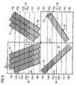
- the radiation patternmay be any suitable radiation pattern, for example a stripe pattern, see Figure 4 , a chessboard pattern, see Figure 5 , or a pattern comprising arbitrarily shaped sections, wherein the individual sections S of the radiation pattern may be defined by a plurality of substantially parallel scan vectors V.
- the radiation pattern according to which the radiation beams 24a, 24b emitted by the irradiation units 22a, 22b of the irradiation system 20 are guided over subsequent layers of raw material powderare rotated relative to each other.
- a contour C of the three-dimensional work piece to be producedwhich may be a substantially line-shaped inner or outer contour of the three-dimensional work piece, may be defined by a plurality of individual scan points P, see Figures 6 and 7 .
- control device 27which, in a schematic representation, is depicted in greater detail in Figure 3 .
- the various units of the control device 27 shown in Figure 3 and described in the followingmay be implemented in hardware or software as desired.
- the control device 27comprises a definition unit 28 adapted to define the first and the second irradiation area 18a, 18b as well as the overlap area 26 on the surface of the carrier 16.
- a first assigning unit 30serves to assign the first irradiation unit 22a of the irradiation system 20 to the first irradiation area 18a and the overlap area 26, and to assign the second irradiation unit 22b of the irradiation system 20 to the second irradiation area 18b and the overlap area 26.
- the control device 27further comprises a determining unit 32 which is adapted to perform an analysis of the arrangement of the radiation pattern according to which the radiation beams 24a, 24b emitted by the irradiation units 22a, 22b are guided over the layer of raw material powder received on the carrier 16 and/or a contour of the three-dimensional work piece to be produced relative to the irradiation areas 18a, 18b and the overlap area 26 defined on the surface of the carrier 16.
- a determining unit 32which is adapted to perform an analysis of the arrangement of the radiation pattern according to which the radiation beams 24a, 24b emitted by the irradiation units 22a, 22b are guided over the layer of raw material powder received on the carrier 16 and/or a contour of the three-dimensional work piece to be produced relative to the irradiation areas 18a, 18b and the overlap area 26 defined on the surface of the carrier 16.
- the determining unit 32determines that a section S of a radiation pattern and/or a contour C extend(s) into the first and the second irradiation area 18a, 18b defined on the surface of the carrier 16, i.e. if the determining unit 32 determines that a section S of a radiation pattern and/or a contour C extend(s) into more than one irradiation area 18a, 18b exclusively associated with only one irradiation unit 22a, 22b, said section S of the radiation pattern and/or said contour C, under the control of a splitting unit 34 of the control device 27, is split into a first portion S1, C1 and a second portion S2, C2, as depicted in Figures 4 and 6 .
- said section S of the radiation pattern and/or said contour Cis split in a splitting region of the section S of the radiation pattern and/or the contour C which is located in the overlap area 26.
- the sections S of the radiation pattern which extend into the first and the second irradiation area 18a, 18b, in subsequent irradiation steps, i.e. upon irradiating subsequent layers of raw material powder, aside from being rotated relative to each other,are split into a first portion S1 and a second portion S2 in different ones of the plurality of partitioning regions PS1, PS3, PS2, PS4 of the overlap area 26 which are defined by means of a dividing unit 36 of the control device 27.
- a first irradiation step for irradiating a first layer of raw material powder received on the carrier 16the sections S of the radiation pattern are split in a splitting region located in a first partitioning region PS1 of the overlap area 26, see upper left section of Figure 4 .
- a second irradiation step for irradiating a second layer of raw material powder received on the carrier 16the sections S of the radiation pattern are split in a splitting region located in a third partitioning region PS3 of the overlap area 26, see lower left section of Figure 4 .
- a third irradiation step for irradiating a third layer of raw material powder received on the carrier 16the sections S of the radiation pattern are split in a splitting region located in a second partitioning region PS2 of the overlap area 26, see upper right section of Figure 4 .
- a fourth irradiation step for irradiating a fourth layer of raw material powder received on the carrier 16the sections S of the radiation pattern are split in a splitting region located in a fourth partitioning region PS4 of the overlap area 26, see lower right section of Figure 4 .
- the splitting of a contour C, in subsequent irradiation stepsmay be effected in different ones of the plurality of partitioning regions PS1, PS3, PS2, PS4 of the overlap area 26.
- the sections S of a radiation pattern which extend into the first and the second irradiation area 18a, 18bare split into a first and a second portion S1, S2 between adjacent scan vectors V.
- splitting of individual scan vectors Vis avoided.
- a contour C which extends into the first and the second irradiation area 18a, 18b defined on the surface of the carrier 16is split into a first and a second portion C1, C2 at an intersection point I1, I2, I3, I4 which is located in a selected partitioning region PS1, PS2, PS3, PS4 of the overlap area 26, wherein the splitting of the contour C should be effected and which is arranged between a first scan point P1 of the contour C located in the first irradiation area 18a and a second scan point P2 of the contour C located in the second irradiation area 18b.
- the contour C according to Figure 7in a first irradiation step for irradiating a first layer of raw material powder received on the carrier 16, is split at the intersection point I1 located in partitioning region PS1, in a second irradiation step for irradiating a second layer of raw material powder received on the carrier 16, is split at the intersection point I3 located in partitioning region PS3, in a third irradiation step for irradiating a third layer of raw material powder received on the carrier 16, is split at the intersection point I2 located in partitioning region PS2 and in a fourth irradiation step for irradiating a fourth layer of raw material powder received on the carrier 16, is split at the intersection point I4 located in partitioning region PS4.
- Each one of the intersection points I1, I2, I3, I4may be a scan point of the contour C which is already present.
- a plurality of scan points of the contour Care located in a selected partitioning region PS1, PS2, PS3, PS4, wherein the splitting of the contour C should be effected, a scan point closest to a center line of the selected partitioning region PS1, PS2, PS3, PS4 may be selected as the intersection point I1, I2, I3, I4.
- an intersection point I1, I2, I3, I4may be defined, for example as a point located on a center line of the selected partitioning region PS1, PS2, PS3, PS4.
- sections S of a radiation pattern and/or contours C which extend into the first and the second irradiation area 18a, 18bare split in such a manner that the first and the second portion S1, C1, S2, C2 of the section S of the radiation pattern and/or the contour C comprises a predetermined minimum number of predefined elements of said section S of the radiation pattern and/or said contour C.
- Predefined elements of a section S of the radiation patternmay, for example, be the scan vectors V defining the section S of the radiation pattern.
- Predefined elements of a contour Cmay, for example, be the scan points defining the contour C.
- the first portion S1, C1 of the split section S of the radiation pattern and/or the split contour C, under the control of a second assigning unit 38 of the control device 27,is assigned to the first irradiation unit 22a
- the second portion S2, C2 of the split section S of the radiation pattern and/or the split contour C, under the control of the second assigning unit 38 of the control device 27,is assigned to the second irradiation unit 22b.
- the first portion S1, C1 of the section S of the radiation pattern and/or the contour Cis defined by irradiating electromagnetic or particle radiation onto the raw material powder received on the carrier 16 which is provided by the first irradiation unit 22a assigned to the first irradiation area 18a.
- the second portion S2, C2 of the section S of the radiation pattern and/or the contour Cis defined by irradiating electromagnetic or particle radiation onto the raw material powder received on the carrier 16 which is provided by the second irradiation unit 22b assigned to the second irradiation area 18b.
- a first irradiation step for irradiating a first layer of raw material powder received on the carrier 16sections S of the radiation pattern having a center point located in a region of the first partitioning region PS1 which is closer to the first irradiation area 18a, i.e. a region of the first partitioning region PS1 above a center line of the first partitioning region PS1 in Figure 5 , by the second assigning unit 38 of the control device 27, is assigned to the first irradiation unit 22a.
- sections S of the radiation pattern having a center point located in a region of the first partitioning region PS1 which is closer to the second irradiation area 18bi.e.
- Sections S of the radiation pattern and/or contours C which extend into the overlap area 26 and only one of the first and the second irradiation area 18a, 18bare treated similar to sections S of the radiation pattern and/or contours C which in their entirety are located in the overlap area 26, i.e. these sections S of the radiation pattern and/or contours C may be assigned to either the first or the second irradiation unit 22a, 22b.
- a section of the radiation pattern S and/or a contour C which extends into the overlap area 26 and the first irradiation area 18ais assigned to the first irradiation unit 22a
- a section S of the radiation pattern and/or a contour C, which extends into the second irradiation area 18b and the overlap area 26is assigned to the second irradiation unit 22b.
- the control device 27further comprises an adjusting unit 40.
- the adjusting unit 40serves to adjust the section S of the radiation pattern and/or the contour C which extend(s) into the first and the second irradiation area 18a, 18b defined on the surface of the carrier 16 and which is therefore split into a first portion S1, C1, S2, C2 in order to increase or to decrease a distance between the first and the second portion S1, C1, S2, C2 of the section S of the radiation pattern and/or the contour C.
- a distance between adjacent scan vectors V in the splitting region of the section S of the radiation pattern, under the control of the adjusting unit 40may be increased in order to avoid an excessive application of radiation energy into the splitting region of the section S of the radiation pattern, or may be decreased in order to ensure a consistent application of radiation energy also into the splitting region of the section S of the radiation pattern.
- a distance between a first and a second scan point P1, P2 of a contour C, which are located adjacent to an intersection point I1, I2, I3, I4 at which the contour C is splitmay be increased in order to avoid an excessive application of radiation energy into the splitting region of the contour C, or may be decreased in order to ensure a consistent application of radiation energy also into the splitting region of the contour C.
- a control unit 42 of the control device 27serves to control the first and the section irradiation unit 22a, 22b so as to increase or to decrease the power of the radiation beams 24a, 24b emitted by the first and the second irradiation unit 22a, 22b in a part of a section S of the radiation pattern and/or a contour C which extend(s) into the first and the second irradiation area 18a, 18b adjacent to the splitting region of the section S of the radiation pattern and/or the contour C in order to either avoid an excessive application of radiation energy into the splitting region of the section S of the radiation pattern and/or the contour C or to ensure a consistent application of radiation energy into the splitting region of the section S of the radiation pattern and/or the contour C, as desired.
- control unit 42controls the first and the second irradiation unit 22a, 22b of the irradiation system 20 in such a manner that the first and the second portion S1, C1, S2, C2 of the section S of the radiation pattern and/or the contour C which extend(s) into the first and the second irradiation area 18a, 18b and thus split are successively irradiated with a radiation beam 24a, 24b emitted by the first and the second irradiation unit 22a, 2b, respectively.
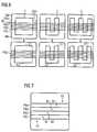
- the first and the second irradiation unit 22a, 22bare controlled in such a manner that, at first, only the first irradiation unit 22a irradiates regions of the first portion S1, C1 of the section S of the radiation pattern which are located in the overlap area 26, whereas the second irradiation unit 22b irradiates regions of the second portion S2, C2 of the section S of the radiation pattern which are located outside of the overlap area 26, see upper left, upper right and lower left part of Figure 8 .
- the second irradiation unit 22bstart irradiating regions of the second portion S2, C2 of the section S of the radiation pattern which are located in the overlap area 26 only after irradiation of the regions of the first portion S1, C1 of the section S of the radiation pattern which are located in the overlap area 26 is completed and the first irradiation unit 22a is operated to irradiate regions of the first portion S1, C1 of the section S of the radiation pattern which are located outside of the overlap area 26.
Landscapes
- Engineering & Computer Science (AREA)
- Physics & Mathematics (AREA)
- Optics & Photonics (AREA)
- Chemical & Material Sciences (AREA)
- Materials Engineering (AREA)
- Mechanical Engineering (AREA)
- Manufacturing & Machinery (AREA)
- Plasma & Fusion (AREA)
- Automation & Control Theory (AREA)
- General Physics & Mathematics (AREA)
- General Engineering & Computer Science (AREA)
- Powder Metallurgy (AREA)
- Exposure And Positioning Against Photoresist Photosensitive Materials (AREA)
- Laser Beam Processing (AREA)
Description
- The present invention relates to a method of and a device for controlling an irradiation system for use in an apparatus for producing a three-dimensional work piece by irradiating layers of a raw material powder with electromagnetic or particle radiation.
- Selective laser melting or laser sintering is an additive layering process by which pulverulent, in particular metallic and/or ceramic raw materials can be processed to three-dimensional work pieces of complex shapes. To that end, a raw material powder layer is applied onto a carrier and subjected to laser radiation in a site selective manner in dependence on the desired geometry of the work piece that is to be produced. The laser radiation penetrating into the powder layer causes heating and consequently melting or sintering of the raw material powder particles. Further raw material powder layers are then applied successively to the layer on the carrier that has already been subjected to laser treatment, until the work piece has the desired shape and size. Selective laser melting or laser sintering can be used in particular for the production of prototypes, tools, replacement parts or medical prostheses, such as, for example, dental or orthopaedic prostheses, on the basis of CAD data.
- An apparatus for producing moulded bodies from pulverulent raw materials by selective laser melting is described, for example, in
EP 1 793 979 A1 - As described in non-published European patent application No.
13 162 179 - Further, as discussed in non-published European patent application No.
13 188 704 - Document
US 2013/0112672 A1 , on which the preamble ofclaims 1 and 9 is based relates to a laser configuration for an additive manufacturing machine and process for improving coverage area and for increasing possible overall part area and volume. A workspace is divided into a plurality of regions with overlapping regions disposed between adjacent ones of the regions. An example additive manufacturing system includes a plurality of energy directing devices that direct laser beams within a corresponding one of the regions within the workspace. Each of the laser beams is directed into a corresponding overlapping area, wherein the overlapping areas include a portion of area within adjacent regions. The invention is directed at the object of providing a method and a device, which allow an irradiation system for use in an apparatus for producing a three-dimensional work piece by irradiating layers of a raw material powder with electromagnetic or particle radiation and comprising a plurality of irradiation units to be controlled in such a manner that a high-quality three-dimensional work piece can be produced. - This object is addressed by a method as defined in
claim 1 and a device as defined in claim 9. - In a method of controlling an irradiation system for use in an apparatus for producing a three-dimensional work piece and comprising a plurality of irradiation units, a first and a second irradiation area as well as an overlap area arranged between the first and the second irradiation area are defined on a surface of a carrier adapted to receive a layer of raw material powder. The carrier may be disposed in a process chamber of the apparatus for producing a three-dimensional work piece and may be a rigidly fixed carrier. Preferably, however, the carrier is designed to be displaceable in vertical direction so that, with increasing construction height of a work piece, as it is built up in layers from the raw material powder, the carrier can be moved downwards in the vertical direction. The process chamber may be sealable against the ambient atmosphere, i.e. against the environment surrounding the process chamber, in order to be able to maintain a controlled atmosphere, in particular an inert atmosphere within the process chamber. The raw material powder to be received on the carrier preferably is a metallic powder, in particular a metal alloy powder, but may also be a ceramic powder or a powder containing different materials. The powder may have any suitable particle size or particle size distribution. It is, however, preferable to process powders of particle sizes < 100 µm.
- The irradiation system to be controlled serves to selectively irradiate the raw material powder applied onto the carrier with electromagnetic or particle radiation. In particular, the raw material powder applied onto the carrier may be subjected to electromagnetic or particle radiation in a site-selective manner in dependence on the desired geometry of the work piece that is to be produced. The irradiation system preferably is adapted to irradiate radiation onto the raw material powder which causes a site-selective melting of the raw material powder particles.
- Each irradiation unit of the irradiation system may comprise a radiation beam source, in particular a laser beam source. It is, however, also conceivable that plural irradiation units are associated with a single radiation beam source, wherein a radiation beam provided by the single radiation beam source, by suitable means such as, for example, beam splitters and/or mirrors, may be split and/or deflected as required so as to direct the radiation beam provided by the radiation beam source to the associated irradiation units. Further, each irradiation unit may comprise at least one optical unit for guiding and/or processing a radiation beam emitted by the radiation beam source and supplied to the irradiation unit. The optical unit may comprise optical elements such as an object lens, in particular an f-theta lens, and a scanner unit, the scanner unit preferably comprising a diffractive optical element and a deflection mirror.
- Each irradiation area defined on the surface of the carrier, i.e. the raw material powder applied thereon, may be selectively irradiated with electromagnetic or particle radiation by a selected one of the irradiation units of the irradiation system independent from the other irradiation units of the irradiation system. Hence, each irradiation area defined on the carrier may be individually and independently irradiated using a desired irradiation pattern. For example, if desired, a small sized three-dimensional work piece may be built-up in only one irradiation area by selectively irradiating the irradiation area with electromagnetic or particle radiation. Preferably, however, the plurality of irradiation areas defined on the carrier are simultaneously irradiated with electromagnetic or particle radiation by suitable controlling the irradiation units of the irradiation system, thus allowing a large three-dimensional work piece to be built-up in an additive layer construction process within a relatively short time and thus at reasonable costs.
- In the method of controlling an irradiation system, a first irradiation unit of the irradiation system is assigned to the first irradiation area and the overlap area. Further, a second irradiation unit of the irradiation system is assigned to the second irradiation area and the overlap area. The first irradiation area then may be selectively irradiated with electromagnetic or particle radiation provided by the first irradiation unit, whereas the second irradiation area may be selectively irradiated with electromagnetic or particle radiation provided by the second irradiation unit. The overlap area arranged between the first and the second irradiation area may be irradiated with electromagnetic or particle radiation provided by either the first or the second irradiation unit. By defining a suitable overlap area between the first and the second irradiation area, portions of a large three-dimensional work piece to be built-up on the carrier, which are disposed in an adjoining region of the first and the second irradiation area may be generated with the desired reliability and high quality. However, the first and the second irradiation unit must be suitably controlled in order to ensure that a three-dimensional work piece extending over more than one irradiation area is built-up with the desired consistency and thus quality.
- The method of controlling an irradiation system therefore involves an analysis of a radiation pattern according to which radiation beams emitted by the irradiation units of the irradiation system are guided over the layer of raw material powder received on the carrier or the already produced layers of the work piece and/or a contour of the three-dimensional work piece to be produced and in particular an analysis of the arrangement of the radiation pattern and/or the contour relative to the irradiation areas and the overlap area defined on the surface of the carrier. The radiation pattern may be any suitable radiation pattern, for example a chessboard pattern, a stripe pattern or a pattern comprising arbitrarily shaped sections, wherein the individual sections of the radiation pattern may be defined by a plurality of scan vectors. For example, the scan vectors, in a section of the radiation pattern, may extend substantially parallel to each other, but may be inclined relative to the scan vectors in an adjacent section of the radiation pattern. The scan vectors may follow straight lines or curved lines. Radiation patterns according to which radiation beams emitted by the irradiation units of the irradiation system are guided over subsequent layers of raw material powder may be rotated relative to each other. By rotating the radiation patterns upon irradiating subsequent layers of raw material powder, excessive shrinkage and residual stresses in the generated work pieces may be minimized. The contour of the three-dimensional work piece to be produced may be a substantially line-shaped inner or outer contour of the three-dimensional work piece to be produced and may be defined by a plurality of individual scan points.
- Specifically, in the method of controlling an irradiation system, a determination step is performed so as to determine whether a section of the radiation pattern according to which radiation beams emitted by the irradiation units of the irradiation system are guided over the layer of raw material powder received on the carrier and/or a contour of the three-dimensional work piece to be produced extend(s) into the first and the second irradiation area defined on the surface of the carrier. In other words, in the determination step, the arrangement of the radiation pattern and the contour relative to the irradiation areas and the overlap area defined on the surface of the carrier is analyzed so as to determine whether a section of the radiation pattern and/or the contour extend(s) into more than one irradiation area exclusively associated with only one irradiation unit.
- If it is determined that a section of the radiation pattern and/or a contour of the three-dimensional work piece to be produced extend(s) into the first and the second irradiation area defined on the surface of the carrier, said section of the radiation pattern and/or said contour is split into a first portion and a second portion. In particular, said section of the radiation pattern and/or said contour is split in a splitting region of the section of the radiation pattern and/or the contour which is located in the overlap area arranged between the first and the second irradiation area. The first portion of said section of the radiation pattern and/or said contour is assigned to the first irradiation unit, whereas the second portion of said section of the radiation pattern and/or said contour is assigned to the second irradiation unit. Thus, the first portion of the section of the radiation pattern and/or the contour is defined by irradiating electromagnetic or particle radiation onto the raw material powder received on the carrier which is provided by the first irradiation unit assigned to the first irradiation area. Similarly, the second portion of the section of the radiation pattern and/or the contour is defined by irradiating electromagnetic or particle radiation onto the raw material powder received on the carrier which is provided by the second irradiation unit assigned to the second irradiation area.
- By splitting sections of the radiation pattern and/or contours which extend into more than one irradiation area exclusively associated with only one irradiation unit into portions and by assigning these portions to suitable irradiation units, the sections of the radiation pattern and/or the contours can be reproduced in a reliable manner, although this would not be possible with a single irradiation unit of the irradiation system. Simultaneously, by defining that only sections of the radiation pattern and/or contours which extend into more than one irradiation area exclusively associated with only one irradiation unit should be split, the number of sections of the radiation pattern and/or contours which are in fact split is reduced to a minimum. As a result, the control of the irradiation units can be simplified and mutual interferences between the radiation beams emitted by the first and the second irradiation unit can be omitted. Consequently, a high-quality three-dimensional work piece can be produced.
- If the analysis of the arrangement of the radiation pattern and/or a contour relative to the irradiation areas and the overlap area defined on the surface of the carrier reveals, that a section of the radiation pattern according to which radiation beams emitted by the irradiation units of the irradiation system are guided over the layer of raw material powder received on the carrier and/or a contour of the three-dimensional work piece to be produced in its entirety is located in the overlap area arranged between the first and the second irradiation area, said section of the radiation pattern and/or said contour preferably is assigned to either the first or the second irradiation unit. Hence, a section of the radiation pattern and/or a contour which in its entirety is located in the overlap area is not split, but assigned to either the first or the second irradiation unit and consequently defined by irradiating electromagnetic or particle radiation onto the raw material powder received on the carrier which is provided by either the first or the second irradiation unit.
- The section of the radiation pattern and/or the contour which in its entirety is located in the overlap area arranged between the first and the second irradiation area may be assigned to the first irradiation unit, if a predefined element of the section of the radiation pattern and/or the contour is located in a region of the overlap area closer to the first irradiation area. To the contrary, the section of the radiation pattern and/or the contour which in its entirety is located in the overlap area arranged between the first and the second irradiation area may be assigned to the second irradiation unit if a predefined element of the section of the radiation pattern and/or the contour is located in a region of the overlap area closer to the second irradiation area. The predefined element of the section of the radiation pattern and/or the contour may, for example, be a center point or a central region of the section of the radiation pattern and/or the contour. For assessing whether the predefined element of the section of the radiation pattern and/or the contour is located closer to the first or the second irradiation area, it is, for example, possible to analyze the position of the predefined element relative to a center line of the overlap area. In case the overlap area is divided into a plurality of partitioning regions as will be described in more detail below, it is also conceivable to analyze the position of the predefined element relative to a center line of a selected partitioning region of the overlap area.
- Sections of the radiation pattern and/or contours which extend into the overlap area and only one of the first and the second irradiation area may be treated similar to sections of the radiation pattern and/or contours which in their entirety are located in the overlap area, i.e. these sections of the radiation pattern and/or contours may be assigned to either the first or the second irradiation unit and hence defined by irradiating electromagnetic or particle radiation onto the raw material powder received on the carrier which is provided by either the first or the second irradiation unit. In particular, a section of the radiation pattern and/or a contour which extends into the overlap area and the first irradiation area preferably is assigned to the first irradiation unit, whereas a section of the radiation pattern and/or a contour, which extends into the second irradiation area and the overlap area preferably is assigned to the second irradiation unit.
- If the analysis of the arrangement of the radiation pattern and/or a contour relative to the irradiation areas and the overlap area defined on the surface of the carrier reveals, that a section of the radiation pattern and/or a contour in its entirety is located in the first irradiation area, said section of the radiation pattern and/or said contour preferably, in its entirety, is assigned to the first irradiation unit. Hence, the section of the radiation pattern and/or the contour, in its entirety, may be defined by irradiating electromagnetic or particle radiation onto the raw material powder received on the carrier which is provided by the first irradiation unit. Similarly, if it is determined, that a section of the radiation pattern and/or a contour, in its entirety, is located in the second irradiation area, said section of the radiation pattern and/or said contour preferably, in its entirety, is assigned to the second irradiation unit and, as a result, the section of the radiation pattern and/or the contour may be defined by irradiation electromagnetic or particle radiation onto the raw material powder received on the carrier which is provided by the second irradiation unit.
- In a preferred embodiment of the method of controlling an irradiation system, the overlap area defined on the surface of the carrier may be divided into a plurality of partitioning regions. For example, the overlap area may be divided into a plurality of partitioning stripes extending substantially parallel to each other. The section of the radiation pattern and/or the contour which extends into the first and the second irradiation area defined on the surface on the carrier may be split into a first portion and a second portion in a selected one of the plurality of partitioning regions. Dividing the overlap area into a plurality of partitioning regions provides the advantage, that the region of the overlap area, wherein the splitting of a section of the radiation pattern and/or a contour which extend(s) into the first and the second irradiation area is effected, in subsequent irradiation steps, may be varied. In other words, if a section of the radiation pattern and/or a contour, in a first irradiation step for irradiating a first layer of raw material powder received on the carrier, is split into a first portion and a second portion in a splitting region of the radiation pattern and/or the contour which is located in a first partitioning region of the overlap area, in a subsequent irradiation step for irradiating a subsequent layer of raw material powder received on the carrier, the splitting of a section of the radiation pattern and/or a contour area may be effected in another partitioning region of the overlap area.
- The variation of the partitioning regions of the overlap area wherein sections of the radiation pattern are split may be effected independent of a rotation of the radiation pattern upon irradiating subsequent layers of raw material powder. The partitioning region, wherein the section of the radiation pattern and/or the contour is split into a first portion and a second portion, in subsequent irradiation steps, may be selected randomly or according to a predetermined order. For example, in case the overlap area is divided into four partitioning stripes, PS1, PS2, PS3, PS4, an order of the partitioning regions, wherein the section of the radiation pattern and/or the contour is split in subsequent irradiation steps, may be PS1, PS3, PS2, PS4.
- Preferably, the section of the radiation pattern and/or the contour which extend(s) into the first and the second irradiation area defined on the surface of the carrier is adjusted in order to increase or to decrease a distance between the first and the second portion of the section of the radiation pattern and/or the contour. For example, in a section of the radiation pattern which is defined by a plurality of substantially parallel scan vectors, a distance between adjacent scan vectors in the splitting region of the section of the radiation pattern may be increased in order to avoid an excessive application of radiation energy into the splitting region of the section of the radiation pattern. Similarly, a contour may be adjusted in order to increase a distance between individual scan points of the contour in the splitting region of the contour, i.e. in the region of an intersection point at which the contour is split. To the contrary, it is, however, also conceivable to adjust a section of the radiation pattern defined by a plurality of substantially parallel scan vectors so as to decrease a distance between adjacent scan vectors in the splitting region of the section of the radiation pattern, or to adjust a contour such that individual scan points of the contour in the splitting region of the contour, i.e. in the region of an intersection point at which the contour is split, are disposed closer to each other, for example in order to ensure a consistent application of radiation energy also into the splitting region of the section of the radiation pattern and/or the contour.
- Alternatively or additionally thereto, at least one of the first and the section irradiation unit may be controlled so as to increase or to decrease the power of a radiation beam emitted by the first and/or the second irradiation unit in a part of the section of the radiation pattern and/or the contour which extend(s) into the first and the second irradiation area adjacent to the splitting region of the section of the radiation pattern and/or the contour. Controlling the power of the radiation beam emitted by the first and/or the second irradiation unit, similar to an adjustment of the section of the radiation pattern and/or the contour, allows to either avoid an excessive application of radiation energy into the splitting region of the section of the radiation pattern and/or the contour or to ensure a consistent application of radiation energy into the splitting region of the section of the radiation pattern and/or the contour, as desired.
- At least one of the first and the second portion of the section of the radiation pattern and/or the contour which extends into the first and the second irradiation area defined on the surface of the carrier may comprise a predetermined minimum number of predefined elements of said section of the radiation pattern and/or said contour. Predefined elements of a section of the radiation pattern may, for example, be scan vectors defining the section of the radiation pattern. Predefined elements of a contour may, for example, be scan points defining the contour. By defining that at least one of the first and the second portion of the section of the radiation pattern and/or the contour should comprise a predetermined minimum number of predefined elements, the generation of portions of the section of the radiation pattern and/or the contour which comprise too few predetermined elements and hence may not be generated with the desired accuracy and reliability, is prevented.
- In a preferred embodiment of the method of controlling an irradiation system, the first and the second irradiation unit of the irradiation system are controlled in such a manner that the first and the second portion of the section of the radiation pattern and/or the contour which extend(s) into the first and the second irradiation area defined on the surface of the carrier are successively irradiated with a radiation beam emitted by the first and the second irradiation unit, respectively. Thereby, interferences between the radiation beams emitted by the first and second irradiation unit may be omitted.
- As already indicated above, the radiation pattern according to which radiation beams emitted by the irradiation units of the irradiation system are guided over the layer of raw material powder received on the carrier may contain a plurality of scan vectors. A section of such a radiation pattern which extends into the first and the second irradiation area defined on the surface of the carrier preferably is split into a first and a second portion between adjacent scan vectors. In other words, upon splitting a section of a radiation pattern defined by a plurality of scan vectors, splitting of individual scan vectors is avoided. Instead, the splitting is effected between adjacent, for example, parallel scan vectors.
- A contour which extends into the first and the second irradiation area defined on the surface of the carrier may be split into a first and a second portion at an intersection point arranged between a first scan point of the contour located in the first irradiation area and a second scan point of the contour located in the second irradiation area. The intersection point, which should be located in the overlap area, in particular a selected partitioning region of the overlap area, may be a scan point which is already present, i.e. a scan point which constitutes a predefined element of the contour. In case a plurality of scan points of the contour are located in the overlap area, in particular the selected partitioning region of the overlap area, a scan point closest to a center line of the overlap area, in particular a center line of the selected partitioning region of the overlap area may be selected as the intersection point. In case, however, the contour does not contain a scan point located in the overlap area, in particular the selected partitioning region of the overlap area, an intersection point may be defined, for example as a point located on a center line of the overlap area, in particular on a center line of the selected partitioning region of the overlap area. A device for controlling an irradiation system for use in an apparatus for producing a three dimensional work piece and comprising a plurality of irradiation units comprises a definition unit adapted to define a first and a second irradiation area as well as an overlap area arranged between the first and the second irradiation area on a surface of a carrier adapted to receive a layer of raw material powder. The device further comprises a first assigning unit adapted to assign a first irradiation unit of the irradiation system to the first irradiation area and the overlap area, and to assign a second irradiation unit of the irradiation system to the second irradiation area and the overlap area. A determining unit of the device is adapted to determine that a section of a radiation pattern according to which radiation beams emitted by the irradiation units of the irradiation system are guided over the layer of raw material powder received on the carrier and/or a contour of the three-dimensional work piece to be produced extend(s) into the first and the second irradiation area defined on the surface of the carrier. The device further comprises a splitting unit adapted to split said section of the radiation pattern and/or said contour, in a splitting region of the radiation pattern and/or the contour which is located in the overlap area arranged between the first and the second irradiation area, into a first portion and a second portion. A second assigning unit is adapted to assign the first portion of said section of the radiation pattern and/or said contour to the first irradiation unit. Furthermore the second assigning unit is adapted to assign the second portion of said section of the radiation pattern and/or said contour to the second irradiation unit.
- The determining unit may be adapted to determine that a section of the radiation pattern according to which radiation beams emitted by the irradiation units of the irradiation system are guided over the layer of raw material powder received on the carrier and/or a contour of the three dimensional work piece to be produced in its entirety is located in the overlap area arranged between the first and the second irradiation area. Furthermore, the second assigning unit may be adapted to assign said section of the radiation pattern and/or said contour to either the first or the second irradiation unit.
- In particular, the second assigning unit may be adapted to assign the section of the radiation pattern and/or the contour which in its entirety is located in the overlap area arranged between the first and the second irradiation area to the first irradiation unit, if a predefined element of the section of the radiation pattern and/or the contour is located in a region of the overlap area closer to the first irradiation area. Moreover, the second assigning unit may be adapted to assign the section of the radiation pattern and/or the contour which in its entirety is located in the overlap area arranged between the first and the second irradiation area to the second irradiation unit, if a predefined element of the section of radiation pattern and/or the contour is located in a region of the overlap area closer to the second irradiation area.
- The device for controlling an irradiation system preferably further comprises a dividing unit adapted to divide the overlap area defined on the surface of the carrier into a plurality of partitioning regions. The splitting unit may further be adapted to split the section of the radiation pattern and/or the contour which extend(s) into the first and the second irradiation area defined on the surface of the carrier into a first portion and a second portion in a selected one of the plurality of partitioning regions and to select the partitioning region wherein said section of radiation pattern and/or the contour is split into a first portion and a second portion, in subsequent irradiation steps, randomly or according to a predetermined order.
- The device for controlling an irradiation system may further comprise an adjusting unit adapted to adjust the section of the radiation pattern and/or the contour which extend(s) into the first and the second irradiation area defined on the surface of the carrier in order to increase or to decrease a distance between the first and the second portion of said section of radiation pattern and/or the contour. Furthermore, the device may comprise a control unit adapted to control at least one of the first and the second irradiation unit so as to increase or to decrease the power of a radiation beam emitted by the first and/or the second irradiation unit in a part of said section of the radiation pattern and/or said contour adjacent to a splitting region of said section of a radiation pattern and/or said contour.
- At least one of the first and the second portion of the section of radiation pattern and/or the contour which extend(s) into the first and the second irradiation area defined on the surface of the carrier may comprise a predetermined minimum number of predefined elements of said section of the radiation pattern and/or said contour.
- The control unit of the device for controlling an irradiation system may further be adapted to control the first and the second irradiation unit in such a manner that the first and the second portion of the section of the radiation pattern and/or the contour which extend(s) into the first and the second irradiation area defined on the surface of the carrier are successively irradiated with a radiation beam emitted by the first and the second radiation unit, respectively.
- The radiation pattern may contain a plurality of scan vectors. The splitting unit then preferably is adapted to split the section of the radiation pattern which extends into the first and the second irradiation area defined on the surface on the carrier into a first and a second portion between adjacent scan vectors. Furthermore, the splitting unit may be adapted to split the contour which extends into the first and the second irradiation area defined on the surface of the carrier into a first and a second portion at an intersection point arranged between a first scan point of the contour located in the first irradiation area and a second scan point of the contour located in the second irradiation area.
- Furthermore, the device for controlling an irradiation system may comprise further features which are explained in greater detail above in connection with the method for controlling an irradiation system. In other words, features described herein with reference to a method of controlling an irradiation system may be transferred to a device for controlling an irradiation system and vice versa.
- Preferred embodiments of the invention in the following are explained in greater detail with reference to the accompanying schematic drawings, in which:
- Figure 1
- shows a schematic representation of an apparatus for producing three-dimensional work pieces,
- Figure 2
- shows a top view of a carrier of the apparatus depicted in
Figure 1 , - Figure 3
- shows a more detailed view of a device for controlling an irradiation system of the apparatus depicted in
Figure 1 , - Figure 4
- shows the splitting of a section of a radiation pattern, which extends into a first and a second irradiation area defined on a surface of a carrier of the apparatus depicted in
Figure 1 , into a first portion which is assigned to a first irradiation unit of the apparatus depicted inFigure 1 and second portion which is assigned to a second irradiation unit of the apparatus depicted inFigure 1 , - Figure 5
- shows the assigning of sections of a radiation pattern, which in their entirety are located in an overlap area defined on the surface of the carrier of the apparatus depicted in
Figure 1 , to either the first or the second irradiation unit of the apparatus depicted inFigure 1 , - Figure 6
- shows the splitting of different contours, which extend into the first and the second irradiation area defined on the surface of the carrier of the apparatus depicted in
Figure 1 , into a first portion which is assigned to a first irradiation unit of the apparatus depicted inFigure 1 and second portion which is assigned to a second irradiation unit of the apparatus depicted inFigure 1 , - Figure 7
- shows the identification of an intersection point at which a contour is split into a first and a second portion, and
- Figure 8
- shows an example of how sections of a radiation pattern which are located in the overlap area defined on the surface of the carrier of the apparatus depicted in
Figure 1 and which are assigned to either the first and the second irradiation unit of the apparatus depicted inFigure 1 are irradiated in a successive order. Figure 1 shows anapparatus 10 for producing three-dimensional work pieces by selective laser melting (SLM®). Theapparatus 10 comprises aprocess chamber 12. Theprocess chamber 12 is sealable against the ambient atmosphere, i.e. against the environment surrounding theprocess chamber 12. Apowder application device 14, which is disposed in theprocess chamber 12, serves to apply a raw material powder onto acarrier 16. As indicated by an arrow A inFigure 1 , thecarrier 16 is designed to be displaceable in a vertical direction so that, with increasing construction height of a work piece, as it is built up in layers from the raw material powder on thecarrier 16, thecarrier 16 can be moved downwards in the vertical direction. As becomes apparent fromFigure 2 , a first and asecond irradiation area carrier 16.- The
apparatus 10 further comprises anirradiation system 20 for selectively irradiating laser radiation onto the raw material powder applied onto thecarrier 16. By means of theirradiation system 20, the raw material powder applied onto thecarrier 16 may be subjected to laser radiation in a site-selective manner in dependence on the desired geometry of the work piece that is to be produced. Theirradiation system 20 comprises a first and asecond irradiation unit first irradiation unit 22a is associated with thefirst irradiation area 18a defined on the surface of thecarrier 16 and is configured to selectively irradiate an electromagnetic orparticle radiation beam 24a onto the raw material powder applied onto thefirst irradiation area 18a. Thesecond irradiation unit 22b is associated with thesecond irradiation area 18b defined on the surface of thecarrier 16 and is configured to selectively irradiate an electromagnetic orparticle radiation beam 24b onto the raw material powder applied onto thesecond irradiation area 18b. - Each
irradiation unit irradiation units irradiation units irradiation unit irradiation units - Further, each
irradiation unit irradiation unit irradiation system 20 is controlled by means of acontrol device 27. - By means of the
control device 27, eachirradiation unit radiation beam irradiation unit irradiation area irradiation unit other irradiation area irradiation unit irradiation area carrier 16 is individually and independently irradiated using a desired irradiation pattern. Thus, a large three-dimensional work piece may be built-up on thecarrier 16 in an additive layer construction process within a relatively short time and at reasonable costs by simultaneously irradiating the first and thesecond irradiation area carrier 16 with electromagnetic or particle radiation emitted by theirradiation units - Beside the
irradiation areas overlap area 26 is defined on the surface of thecarrier 16, seeFigure 2 . Raw material powder applied onto theoverlap area 26 is selectively irradiatable with electromagnetic or particle radiation by bothirradiation units irradiation system 20. Inoverlap area 26 has the form of a stripe which is arranged between the first and thesecond irradiation area overlap area 26 is divided into a plurality of partitioning regions PS1, PS2, PS3, PS4. In particular, theoverlap area 26 is divided into four partitioning regions PS1, PS2, PS3, PS4 in the form of partitioning stripes extending substantially parallel to each other. - The radiation beams 24a, 24b emitted by the
irradiation units irradiation system 20 are guided over the layer of raw material powder received on thecarrier 16 according to a predefined radiation pattern. The radiation pattern may be any suitable radiation pattern, for example a stripe pattern, seeFigure 4 , a chessboard pattern, seeFigure 5 , or a pattern comprising arbitrarily shaped sections, wherein the individual sections S of the radiation pattern may be defined by a plurality of substantially parallel scan vectors V. The radiation pattern according to which theradiation beams irradiation units irradiation system 20 are guided over subsequent layers of raw material powder are rotated relative to each other. A contour C of the three-dimensional work piece to be produced, which may be a substantially line-shaped inner or outer contour of the three-dimensional work piece, may be defined by a plurality of individual scan points P, seeFigures 6 and 7 . - As already indicated above, the operation of the
irradiation system 20 is controlled by means of thecontrol device 27 which, in a schematic representation, is depicted in greater detail inFigure 3 . The various units of thecontrol device 27 shown inFigure 3 and described in the following may be implemented in hardware or software as desired. Thecontrol device 27 comprises adefinition unit 28 adapted to define the first and thesecond irradiation area overlap area 26 on the surface of thecarrier 16. A first assigningunit 30 serves to assign thefirst irradiation unit 22a of theirradiation system 20 to thefirst irradiation area 18a and theoverlap area 26, and to assign thesecond irradiation unit 22b of theirradiation system 20 to thesecond irradiation area 18b and theoverlap area 26. Thecontrol device 27 further comprises a determiningunit 32 which is adapted to perform an analysis of the arrangement of the radiation pattern according to which theradiation beams irradiation units carrier 16 and/or a contour of the three-dimensional work piece to be produced relative to theirradiation areas overlap area 26 defined on the surface of thecarrier 16. - If the determining
unit 32 determines that a section S of a radiation pattern and/or a contour C extend(s) into the first and thesecond irradiation area carrier 16, i.e. if the determiningunit 32 determines that a section S of a radiation pattern and/or a contour C extend(s) into more than oneirradiation area irradiation unit splitting unit 34 of thecontrol device 27, is split into a first portion S1, C1 and a second portion S2, C2, as depicted inFigures 4 and6 . In particular, said section S of the radiation pattern and/or said contour C is split in a splitting region of the section S of the radiation pattern and/or the contour C which is located in theoverlap area 26. - As becomes apparent from
Figure 4 , the sections S of the radiation pattern which extend into the first and thesecond irradiation area overlap area 26 which are defined by means of a dividingunit 36 of thecontrol device 27. Specifically, in a first irradiation step for irradiating a first layer of raw material powder received on thecarrier 16, the sections S of the radiation pattern are split in a splitting region located in a first partitioning region PS1 of theoverlap area 26, see upper left section ofFigure 4 . In a second irradiation step for irradiating a second layer of raw material powder received on thecarrier 16, the sections S of the radiation pattern are split in a splitting region located in a third partitioning region PS3 of theoverlap area 26, see lower left section ofFigure 4 . In a third irradiation step for irradiating a third layer of raw material powder received on thecarrier 16, the sections S of the radiation pattern are split in a splitting region located in a second partitioning region PS2 of theoverlap area 26, see upper right section ofFigure 4 . Finally, in a fourth irradiation step for irradiating a fourth layer of raw material powder received on thecarrier 16, the sections S of the radiation pattern are split in a splitting region located in a fourth partitioning region PS4 of theoverlap area 26, see lower right section ofFigure 4 . Likewise, also the splitting of a contour C, in subsequent irradiation steps may be effected in different ones of the plurality of partitioning regions PS1, PS3, PS2, PS4 of theoverlap area 26. - As becomes apparent from
Figure 4 , the sections S of a radiation pattern which extend into the first and thesecond irradiation area - As depicted in
Figures 6 and 7 , a contour C which extends into the first and thesecond irradiation area carrier 16 is split into a first and a second portion C1, C2 at an intersection point I1, I2, I3, I4 which is located in a selected partitioning region PS1, PS2, PS3, PS4 of theoverlap area 26, wherein the splitting of the contour C should be effected and which is arranged between a first scan point P1 of the contour C located in thefirst irradiation area 18a and a second scan point P2 of the contour C located in thesecond irradiation area 18b. In particular, the contour C according toFigure 7 , in a first irradiation step for irradiating a first layer of raw material powder received on thecarrier 16, is split at the intersection point I1 located in partitioning region PS1, in a second irradiation step for irradiating a second layer of raw material powder received on thecarrier 16, is split at the intersection point I3 located in partitioning region PS3, in a third irradiation step for irradiating a third layer of raw material powder received on thecarrier 16, is split at the intersection point I2 located in partitioning region PS2 and in a fourth irradiation step for irradiating a fourth layer of raw material powder received on thecarrier 16, is split at the intersection point I4 located in partitioning region PS4. - Each one of the intersection points I1, I2, I3, I4 may be a scan point of the contour C which is already present. In case a plurality of scan points of the contour C are located in a selected partitioning region PS1, PS2, PS3, PS4, wherein the splitting of the contour C should be effected, a scan point closest to a center line of the selected partitioning region PS1, PS2, PS3, PS4 may be selected as the intersection point I1, I2, I3, I4. In case, however, the contour C does not contain a scan point located in the selected partitioning region PS1, PS2, PS3, PS4, wherein the splitting of the contour C should be effected, an intersection point I1, I2, I3, I4 may be defined, for example as a point located on a center line of the selected partitioning region PS1, PS2, PS3, PS4.
- Under the control of the
splitting unit 34, sections S of a radiation pattern and/or contours C which extend into the first and thesecond irradiation area - The first portion S1, C1 of the split section S of the radiation pattern and/or the split contour C, under the control of a second assigning
unit 38 of thecontrol device 27, is assigned to thefirst irradiation unit 22a, whereas the second portion S2, C2 of the split section S of the radiation pattern and/or the split contour C, under the control of the second assigningunit 38 of thecontrol device 27, is assigned to thesecond irradiation unit 22b. Thus, the first portion S1, C1 of the section S of the radiation pattern and/or the contour C is defined by irradiating electromagnetic or particle radiation onto the raw material powder received on thecarrier 16 which is provided by thefirst irradiation unit 22a assigned to thefirst irradiation area 18a. Similarly, the second portion S2, C2 of the section S of the radiation pattern and/or the contour C is defined by irradiating electromagnetic or particle radiation onto the raw material powder received on thecarrier 16 which is provided by thesecond irradiation unit 22b assigned to thesecond irradiation area 18b. - If the analysis of the arrangement of the radiation pattern and/or a contour C relative to the
irradiation areas overlap area 26 performed by the determiningunit 32 of thecontrol device 27 reveals, that a section S of the radiation pattern and/or a contour C in its entirety is located in theoverlap area 26, said section S of the radiation pattern and/or said contour C, by the second assigningunit 38 of thecontrol device 27, is assigned to either the first or thesecond irradiation unit Figure 5 . A contour C which in its entirety is located in theoverlap area 26, however, may be treated likewise. - In a first irradiation step for irradiating a first layer of raw material powder received on the
carrier 16, sections S of the radiation pattern having a center point located in a region of the first partitioning region PS1 which is closer to thefirst irradiation area 18a, i.e. a region of the first partitioning region PS1 above a center line of the first partitioning region PS1 inFigure 5 , by the second assigningunit 38 of thecontrol device 27, is assigned to thefirst irradiation unit 22a. To the contrary, sections S of the radiation pattern having a center point located in a region of the first partitioning region PS1 which is closer to thesecond irradiation area 18b, i.e. a region of the first partitioning region PS1 below a center line of the first partitioning region PS1 inFigure 5 , by the second assigningunit 38 of thecontrol device 27, is assigned to thesecond irradiation unit 22b, see upper left section ofFigure 5 . The same assignment steps are performed in a second irradiation step for irradiating a second layer of raw material powder received on thecarrier 16, see lower left section ofFigure 4 , a third irradiation step for irradiating a third layer of raw material powder received on thecarrier 16, see upper right section ofFigure 4 and a fourth irradiation step for irradiating a fourth layer of raw material powder received on thecarrier 16, see lower right section ofFigure 4 , wherein the partitioning region PS1, PS3, PS2, PS4 in subsequent irradiation steps is varied as described above in connection with the splitting of radiation pattern sections S and contours C. - Sections S of the radiation pattern and/or contours C which extend into the
overlap area 26 and only one of the first and thesecond irradiation area overlap area 26, i.e. these sections S of the radiation pattern and/or contours C may be assigned to either the first or thesecond irradiation unit overlap area 26 and thefirst irradiation area 18a is assigned to thefirst irradiation unit 22a, whereas a section S of the radiation pattern and/or a contour C, which extends into thesecond irradiation area 18b and theoverlap area 26 is assigned to thesecond irradiation unit 22b. - If the analysis of the arrangement of the radiation pattern and/or a contour C relative to the
irradiation areas overlap area 26 performed by the determiningunit 32 of thecontrol device 27 reveals that a section S of the radiation pattern and/or a contour C in its entirety is located in thefirst irradiation area 18a, said section S of the radiation pattern and/or said contour C, in its entirety, is assigned to thefirst irradiation unit 22a. Similarly, if it is determined, that a section S of the radiation pattern and/or a contour C, in its entirety, is located in thesecond irradiation area 18b, said section S of the radiation pattern and/or said contour C, in its entirety, is assigned to thesecond irradiation unit 22b. - The
control device 27 further comprises an adjustingunit 40. The adjustingunit 40 serves to adjust the section S of the radiation pattern and/or the contour C which extend(s) into the first and thesecond irradiation area carrier 16 and which is therefore split into a first portion S1, C1, S2, C2 in order to increase or to decrease a distance between the first and the second portion S1, C1, S2, C2 of the section S of the radiation pattern and/or the contour C. For example, a distance between adjacent scan vectors V in the splitting region of the section S of the radiation pattern, under the control of the adjustingunit 40 may be increased in order to avoid an excessive application of radiation energy into the splitting region of the section S of the radiation pattern, or may be decreased in order to ensure a consistent application of radiation energy also into the splitting region of the section S of the radiation pattern. Similarly, a distance between a first and a second scan point P1, P2 of a contour C, which are located adjacent to an intersection point I1, I2, I3, I4 at which the contour C is split, may be increased in order to avoid an excessive application of radiation energy into the splitting region of the contour C, or may be decreased in order to ensure a consistent application of radiation energy also into the splitting region of the contour C. - Moreover, a
control unit 42 of thecontrol device 27 serves to control the first and thesection irradiation unit radiation beams second irradiation unit second irradiation area - Further, the
control unit 42 controls the first and thesecond irradiation unit irradiation system 20 in such a manner that the first and the second portion S1, C1, S2, C2 of the section S of the radiation pattern and/or the contour C which extend(s) into the first and thesecond irradiation area radiation beam second irradiation unit 22a, 2b, respectively. As becomes apparent fromFigure 8 , the first and thesecond irradiation unit first irradiation unit 22a irradiates regions of the first portion S1, C1 of the section S of the radiation pattern which are located in theoverlap area 26, whereas thesecond irradiation unit 22b irradiates regions of the second portion S2, C2 of the section S of the radiation pattern which are located outside of theoverlap area 26, see upper left, upper right and lower left part ofFigure 8 . Thesecond irradiation unit 22b start irradiating regions of the second portion S2, C2 of the section S of the radiation pattern which are located in theoverlap area 26 only after irradiation of the regions of the first portion S1, C1 of the section S of the radiation pattern which are located in theoverlap area 26 is completed and thefirst irradiation unit 22a is operated to irradiate regions of the first portion S1, C1 of the section S of the radiation pattern which are located outside of theoverlap area 26.
Claims (15)
- Method of controlling an irradiation system (20) for use in an apparatus (10) for producing a three-dimensional work piece and comprising a plurality of irradiation units (22a, 22b), the method comprising the steps of:- defining a first and a second irradiation area (18a, 18b) as well as an overlap area (26) arranged between the first and the second irradiation area (18a, 18b) on a surface of a carrier (16) adapted to receive a layer of raw material powder,- assigning a first irradiation unit (22a) of the irradiation system (20) to the first irradiation area (18a) and the overlap area (26), and- assigning a second irradiation unit (22b) of the irradiation system (20) to the second irradiation area (18b) and the overlap area (26),characterized by the steps of:- determining that a section (S) of a radiation pattern according to which radiation beams (24a, 24b) emitted by the irradiation units (22a, 22b) of the irradiation system (20) are guided over the layer of raw material powder received on the carrier (16) and/or a contour (C) of the three-dimensional work piece to be produced extend(s) into the first and the second irradiation area (18a, 18b) defined on the surface of the carrier (16),- splitting said section (S) of the radiation pattern and/or said contour (C), in a splitting region of the section (S) of the radiation pattern and/or the contour (C) which is located in the overlap area (26) arranged between the first and the second irradiation area (18a, 18b), into a first portion (S1, C1) and a second portion (S2, C2),- assigning the first portion (S1, C1) of said section (S) of the radiation pattern and/or said contour (C) to the first irradiation unit (22a), and- assigning the second portion (S2, C2) of said section (S) of the radiation pattern and/or said contour (C) to the second irradiation unit (22b).
- Method according to claim 1,
further comprising the steps of:- determining that a section (S) of the radiation pattern according to which radiation beams (24a, 24b) emitted by the irradiation units (22a, 22b) of the irradiation system (20) are guided over the layer of raw material powder received on the carrier (16) and/or a contour (C) of the three-dimensional work piece to be produced in its entirety is located in the overlap area (26) arranged between the first and the second irradiation area (18a, 18b), and- assigning said section (S) of the radiation pattern and/or said contour (C) to either the first or the second irradiation unit (22a, 22b). - Method according to claim 2,
wherein the section (S) of the radiation pattern and/or the contour (C) which in its entirety is located in the overlap area (26) arranged between the first and the second irradiation area (18a, 18b) is assigned to the first irradiation unit (22a), if a predefined element of the section (S) of the radiation pattern and/or the contour (C) is located in a region of the overlap area (26) closer to the first irradiation area (18a), and/or wherein the section (S) of the radiation pattern and/or the contour (C) which in its entirety is located in the overlap area (26) arranged between the first and the second irradiation area (18a, 18b) is assigned to the second irradiation unit (22b), if a predefined element of the section (S) of the radiation pattern and/or the contour (C) is located in a region of the overlap area (26) closer to the second irradiation area (18b) - Method according to any one of claims 1 to 3,
further comprising the steps of:- dividing the overlap area (26) defined on the surface of the carrier (16) into a plurality of partitioning regions (PS1, PS2, PS3, PS4), and- splitting the section (S) of the radiation pattern and/or the contour (C) which extend(s) into the first and the second irradiation area (18a, 18b) defined on the surface of the carrier (16) into a first portion (S1, C1) and a second portion (S2, C2) in a selected one of the plurality of partitioning regions (PS1, PS2, PS3, PS4), wherein the partitioning region (PS1, PS2, PS3, PS4) wherein the section (S) of the radiation pattern and/or the contour (C) is split into a first portion (S1, C1) and a second portion (S2, C2), in subsequent irradiation steps, is selected randomly or according to a predetermined order. - Method according to any one of claims 1 to 4,
comprising at least one of the further steps:- adjusting the section (S) of the radiation pattern and/or the contour (C) which extend(s) into the first and the second irradiation area (18a, 18b) defined on the surface of the carrier (16) in order to increase or to decrease a distance between the first and the second portion (S1, C1, S2, C2) of the section (S) of the radiation pattern and/or the contour (C), and- controlling at least one of the first and the second irradiation unit (22a, 22b) so as to increase or to decrease the power of a radiation beam emitted by the first and/or the second irradiation unit (22a, 22b) in a part of said section (S) of the radiation pattern and/or said contour (C) adjacent to the splitting region of said section (S) of the radiation pattern and/or said contour (C). - Method according to any one of claims 1 to 5,
wherein at least one of the first and the second portion (S1, C1, S2, C2) of the section (S) of the radiation pattern and/or the contour (C) which extend(s) into the first and the second irradiation area (18a, 18b) defined on the surface of the carrier (16) comprises a predetermined minimum number of predefined elements of said section (S) of the radiation pattern and/or said contour (C). - Method according to any one of claims 1 to 6,
wherein the first and the second irradiation unit (22a, 22b) are controlled in such a manner that the first and the second portion (S1, C1, S2, C2) of the section (S) of the radiation pattern and/or the contour (C) which extend(s) into the first and the second irradiation area (18a, 18b) defined on the surface of the carrier (16) are successively irradiated with a radiation beam emitted by the first and the second irradiation unit (22a, 22b), respectively. - Method according to any one of claims 1 to 7,
wherein the radiation pattern contains a plurality of scan vectors (V), and wherein the section (S) of the radiation pattern which extends into the first and the second irradiation area (18a, 18b) defined on the surface of the carrier (16) is split into a first and a second portion (S1, C1, S2, C2) between adjacent scan vectors (V), and/or
wherein the contour (C) which extends into the first and the second irradiation area (18a, 18b) defined on the surface of the carrier (16) is split into a first and a second portion (S1, C1, S2, C2) at an intersection point (I1, I2, I3, I4) arranged between a first scan point (P1) of the contour (C) located in the first irradiation area (18a) and a second scan point (P2) of the contour (C) located in the second irradiation area (18b). - Device (27) for controlling an irradiation system (20) for use in an apparatus (10) for producing a three-dimensional work piece and comprising a plurality of irradiation units (22a, 22b), the device comprising:- a definition unit (28) adapted to define a first and a second irradiation area (18a, 18b) as well as an overlap area (26) arranged between the first and the second irradiation area (18a, 18b) on a surface of a carrier (16) adapted to receive a layer of raw material powder, and- a first assigning unit (30) adapted to assign a first irradiation unit (22a) of the irradiation system (20) to the first irradiation area (18a) and the overlap area (26), and to assign a second irradiation unit (22b) of the irradiation system (20) to the second irradiation area (18a) and the overlap area (26),characterized by:- a determining unit (32) adapted to determine that a section (S) of a radiation pattern according to which radiation beams (24a, 24b) emitted by the irradiation units (22) of the irradiation system (20) are guided over the layer of raw material powder received on the carrier (16) and/or a contour (C) of the three-dimensional work piece to be produced extend(s) into the first and the second irradiation area (18a, 18b) defined on the surface of the carrier (16),- a splitting unit (34) adapted to split said section (S) of the radiation pattern and/or said contour (C), in a splitting region of the radiation pattern and/or the contour (C) which is located in the overlap area (26) arranged between the first and the second irradiation area (18a, 18b), into a first portion (S1, C1) and a second portion (S2, C2), and- a second assigning unit (38) adapted to assign the first portion (S1, C1) of said section (S) of the radiation pattern and/or said contour (C) to the first irradiation unit (22a) and to assign the second portion (S2, C2) of said section (S) of the radiation pattern and/or said contour (C) to the second irradiation unit (22b).
- Device according to claim 9,
wherein- the determining unit (32) is adapted to determine that a section (S) of the radiation pattern according to which radiation beams (24a, 24b) emitted by the irradiation units (22) of the irradiation system (20) are guided over the layer of raw material powder received on the carrier (16) and/or a contour (C) of the three-dimensional work piece to be produced in its entirety is located in the overlap area (26) arranged between the first and the second irradiation area (18a, 18b), and wherein- the second assigning unit (38) is adapted to assign said section (S) of the radiation pattern and/or said contour (C) to either the first or the second irradiation unit (18a, 18b), the second assigning unit (38) in particular further being adapted to assign the section (S) of the radiation pattern and/or the contour (C) which in its entirety is located in the overlap area (26) arranged between the first and the second irradiation area (18a, 18b) to the first irradiation unit (22a), if a predefined element of the section (S) of the radiation pattern and/or the contour (C) is located in a region of the overlap area (26) closer to the first irradiation area (18a), and/or to assign the section (S) of the radiation pattern and/or the contour (C) which in its entirety is located in the overlap area (26) arranged between the first and the second irradiation area (18a, 18b) to the second irradiation unit (22b), if a predefined element of the section (S) of the radiation pattern and/or the contour (C) is located in a region of the overlap area (26) closer to the second irradiation area (18b). - Device according to claim 9 or 10,
further comprising:- a dividing unit (36) adapted to divide the overlap area (26) defined on the surface of the carrier (16) into a plurality of partitioning regions (PS1, PS2, PS3, PS4),wherein- the splitting unit (34) is adapted to split the section (S) of the radiation pattern and/or the contour (C) which extend(s) into the first and the second irradiation area (18a, 18b) defined on the surface of the carrier (16) into a first portion (S1, C1) and a second portion (S2, C2) in a selected one of the plurality of partitioning regions (PS1, PS2, PS3, PS4) and to select the partitioning region (PS1, PS2, PS3, PS4) wherein said section (S) of the radiation pattern and/or the contour (C) is split into a first portion (S1, C1) and a second portion (S2, C2), in subsequent irradiation steps, randomly or according to a predetermined order. - Device according to any one of claims 9 to 11,
further comprising at least one of:- an adjusting unit (40) adapted to adjust the section (S) of the radiation pattern and/or the contour (C) which extend(s) into the first and the second irradiation area (18a, 18b) defined on the surface of the carrier (16) in order to increase or to decrease a distance between the first and the second portion (S1, C1, S2, C2) of said section (S) of the radiation pattern and/or said contour (C), and- a control unit (42) adapted to control at least one of the first and the second irradiation unit (22a, 22b) so as to increase or to decrease the power of a radiation beam emitted by the first and/or the second irradiation unit (22a, 22b) in a part of said section (S) of the radiation pattern and/or said contour (C) adjacent to the splitting region of said section (S) of the radiation pattern and/or said contour (C). - Device according to any one of claims 9 to 12,
wherein at least one of the first and the second portion (S1, C1, S2, C2) of the section (S) of the radiation pattern and/or the contour (C) which extend(s) into the first and the second irradiation area (18a, 18b) defined on the surface of the carrier (16) comprises a predetermined minimum number of predefined elements of said section (S) of the radiation pattern and/or said contour (C). - Device according to any one of claims 9 to 13,
wherein the control unit (42) is adapted to control the first and the second irradiation unit (22a, 22b) in such a manner that the first and the second portion (S1, C1, S2, C2) of the section (S) of the radiation pattern and/or the contour (C) which extend(s) into the first and the second irradiation area (18a, 18b) defined on the surface of the carrier (16) are successively irradiated with a radiation beam emitted by the first and the second irradiation unit (22a, 22b), respectively. - Device according to any one of claims 9 to 14,
wherein the radiation pattern contains a plurality of scan vectors (V), and wherein the splitting unit (34) is adapted to split the section (S) of the radiation pattern which extends into the first and the second irradiation area (18a, 18b) defined on the surface of the carrier (16) into a first and a second portion (S1, C1, S2, C2) between adjacent scan vectors (V) and/or to split the contour (C) which extends into the first and the second irradiation area (18a, 18b) defined on the surface of the carrier (16) into a first and a second portion (S1, C1, S2, C2) at an intersection point (I1, I2, I3, I4) arranged between a first scan point (P1) of the contour (C) located in the first irradiation area (18a) and a second scan point (P2) of the contour (C) located in the second irradiation area (18b).
Priority Applications (3)
| Application Number | Priority Date | Filing Date | Title |
|---|---|---|---|
| EP13193905.0AEP2875897B1 (en) | 2013-11-21 | 2013-11-21 | Method of and device for controlling an irradiation system for producing a three-dimensional workpiece |
| JP2014237039AJP6093339B2 (en) | 2013-11-21 | 2014-11-21 | Method and apparatus for controlling an irradiation system |
| US14/550,439US9878497B2 (en) | 2013-11-21 | 2014-11-21 | Method and device for controlling an irradiation system |
Applications Claiming Priority (1)
| Application Number | Priority Date | Filing Date | Title |
|---|---|---|---|
| EP13193905.0AEP2875897B1 (en) | 2013-11-21 | 2013-11-21 | Method of and device for controlling an irradiation system for producing a three-dimensional workpiece |
Publications (2)
| Publication Number | Publication Date |
|---|---|
| EP2875897A1 EP2875897A1 (en) | 2015-05-27 |
| EP2875897B1true EP2875897B1 (en) | 2016-01-20 |
Family
ID=49639763
Family Applications (1)
| Application Number | Title | Priority Date | Filing Date |
|---|---|---|---|
| EP13193905.0AActiveEP2875897B1 (en) | 2013-11-21 | 2013-11-21 | Method of and device for controlling an irradiation system for producing a three-dimensional workpiece |
Country Status (3)
| Country | Link |
|---|---|
| US (1) | US9878497B2 (en) |
| EP (1) | EP2875897B1 (en) |
| JP (1) | JP6093339B2 (en) |
Cited By (14)
| Publication number | Priority date | Publication date | Assignee | Title |
|---|---|---|---|---|
| EP3241668A1 (en) | 2016-05-04 | 2017-11-08 | SLM Solutions Group AG | Device and method for calibrating an irradiation system of an apparatus for producing a three-dimensional work piece |
| DE102017202725B3 (en) | 2017-02-21 | 2018-07-19 | SLM Solutions Group AG | Apparatus and method for calibrating an irradiation system used to manufacture a three-dimensional workpiece |
| US10112260B2 (en) | 2016-01-20 | 2018-10-30 | General Electric Company | Aligning lasers of laser additive manufacturing system |
| DE102017212565A1 (en) | 2017-07-21 | 2019-01-24 | Trumpf Laser- Und Systemtechnik Gmbh | Method for producing a coherent surface area, irradiation device and processing machine |
| WO2019034259A1 (en) | 2017-08-18 | 2019-02-21 | Fraunhofer-Gesellschaft zur Förderung der angewandten Forschung e. V. | METHOD FOR MACHINING A MATERIAL LAYER WITH ENERGETIC RADIATION OF VARIABLE ENERGY DISTRIBUTION |
| US10317881B2 (en) | 2017-03-01 | 2019-06-11 | General Electric Company | Parallelized CAD using multi laser additive printing |
| US10338569B2 (en) | 2017-08-15 | 2019-07-02 | General Electric Company | Selective modification of build strategy parameter(s) for additive manufacturing |
| WO2019161886A1 (en) | 2018-02-20 | 2019-08-29 | SLM Solutions Group AG | Method for aligning a multi beam irradiation system |
| DE102018203233A1 (en) | 2018-03-05 | 2019-09-05 | MTU Aero Engines AG | Exposure method, manufacturing method and apparatus for selective laser melting |
| US10406633B2 (en) | 2017-08-15 | 2019-09-10 | General Electric Company | Selective modification of build strategy parameter(s) for additive manufacturing |
| US10471510B2 (en) | 2017-08-15 | 2019-11-12 | General Electric Company | Selective modification of build strategy parameter(s) for additive manufacturing |
| US10589382B2 (en) | 2017-03-30 | 2020-03-17 | General Electric Company | Overlapping border and internal sections of object formed by different AM melting beam sources in overlapping field region |
| US10960603B2 (en) | 2017-09-21 | 2021-03-30 | General Electric Company | Scanning strategy for perimeter and region isolation |
| US12324932B2 (en) | 2022-03-03 | 2025-06-10 | TRUMPF Additive Manufacturing Italia S.r.l. | Method and planning device for planning a locally selective irradiation of a working area, computer program, method and manufacturing device for additively manufacturing an object from a powder material |
Families Citing this family (34)
| Publication number | Priority date | Publication date | Assignee | Title |
|---|---|---|---|---|
| EP3415254A1 (en)* | 2013-06-10 | 2018-12-19 | Renishaw PLC | Selective laser solidification apparatus and method |
| GB201310398D0 (en) | 2013-06-11 | 2013-07-24 | Renishaw Plc | Additive manufacturing apparatus and method |
| GB201505458D0 (en) | 2015-03-30 | 2015-05-13 | Renishaw Plc | Additive manufacturing apparatus and methods |
| JP6483551B2 (en) | 2015-07-03 | 2019-03-13 | 株式会社アスペクト | Powder bed fusion unit |
| EP3120967B1 (en) | 2015-07-20 | 2019-06-12 | SLM Solutions Group AG | Method and device for controlling an irradiation system in dependence on a work piece geometry |
| EP4049772A1 (en) | 2015-10-30 | 2022-08-31 | Seurat Technologies, Inc. | Chamber systems for additive manufacturing |
| US10722943B2 (en) | 2016-01-12 | 2020-07-28 | Hamilton Sundstrand Corporation | Additive manufacturing method |
| US11701819B2 (en) | 2016-01-28 | 2023-07-18 | Seurat Technologies, Inc. | Additive manufacturing, spatial heat treating system and method |
| WO2017132668A1 (en) | 2016-01-29 | 2017-08-03 | Seurat Technologies, Inc. | Additive manufacturing, bond modifying system and method |
| DE102016121649A1 (en) | 2016-11-11 | 2018-05-17 | Cl Schutzrechtsverwaltungs Gmbh | Method for automatable or automated determination of the focus position of a laser beam generated by an exposure device |
| DE102016222261A1 (en) | 2016-11-14 | 2018-05-17 | Trumpf Laser- Und Systemtechnik Gmbh | Process for the layered additive production of components and associated computer program product |
| DE102016226150A1 (en) | 2016-12-23 | 2018-06-28 | Robert Bosch Gmbh | Device for the generative production of workpieces |
| DE102017202843B3 (en) | 2017-02-22 | 2018-07-19 | SLM Solutions Group AG | Method and device for controlling an irradiation system for workpiece production |
| DE102017205051A1 (en)* | 2017-03-24 | 2018-09-27 | Eos Gmbh Electro Optical Systems | Überlappoptimierung |
| DE102017107364A1 (en)* | 2017-04-06 | 2018-10-11 | Amsis Gmbh | Method for the additive production of a three-dimensional component and method for calculating a scanning strategy for the purpose of corresponding activation of a system for the additive production of a three-dimensional component |
| DE102017107362A1 (en)* | 2017-04-06 | 2018-10-11 | Amsis Gmbh | Method for the additive production of a three-dimensional component and method for calculating a scanning strategy for the purpose of corresponding activation of a system for the additive production of a three-dimensional component |
| CN110869210B (en) | 2017-05-11 | 2022-09-13 | 速尔特技术有限公司 | Switchyard beam routing of patterned light for additive manufacturing |
| DE102017219718A1 (en) | 2017-11-07 | 2019-05-09 | Bayerische Motoren Werke Aktiengesellschaft | Method for producing a component and component |
| DE102017126624A1 (en)* | 2017-11-13 | 2019-05-16 | Trumpf Laser- Und Systemtechnik Gmbh | LAYERED LIGHT EXPOSURE IN GENERATIVE MANUFACTURING |
| JP6405028B1 (en) | 2017-11-17 | 2018-10-17 | 株式会社ソディック | Additive manufacturing equipment |
| FR3080306B1 (en)* | 2018-04-19 | 2021-02-19 | Michelin & Cie | ADDITIVE MANUFACTURING PROCESS OF A METAL PART IN THREE DIMENSIONS |
| US11426818B2 (en) | 2018-08-10 | 2022-08-30 | The Research Foundation for the State University | Additive manufacturing processes and additively manufactured products |
| KR101992782B1 (en)* | 2018-11-08 | 2019-06-26 | 주식회사 에스에이치솔텍 | The internal arcing fault energy absorber and gas venting device for gas insulated switchgear on underground distribution line |
| US12011873B2 (en) | 2018-12-14 | 2024-06-18 | Seurat Technologies, Inc. | Additive manufacturing system for object creation from powder using a high flux laser for two-dimensional printing |
| SG11202106043WA (en) | 2018-12-19 | 2021-07-29 | Seurat Technologies Inc | Additive manufacturing system using a pulse modulated laser for two-dimensional printing |
| JP7206395B2 (en) | 2018-12-27 | 2023-01-17 | レイヤーワイズ エヌヴェ | A 3D printing system that optimizes contouring for multiple energy beams |
| EP3983152B1 (en)* | 2019-06-13 | 2024-07-17 | Nikon SLM Solutions AG | Apparatus and method for producing a three-dimensional work piece |
| KR102300828B1 (en)* | 2019-10-25 | 2021-09-09 | 참엔지니어링(주) | Dual scanner 3D printer using selective laser sintering |
| JP6793806B1 (en)* | 2019-12-04 | 2020-12-02 | 株式会社ソディック | Laminated modeling equipment |
| US20220152934A1 (en)* | 2020-11-13 | 2022-05-19 | General Electric Company | Irradiation regimes for additive manufacturing machines |
| US12162074B2 (en) | 2020-11-25 | 2024-12-10 | Lawrence Livermore National Security, Llc | System and method for large-area pulsed laser melting of metallic powder in a laser powder bed fusion application |
| US12403650B2 (en) | 2022-07-15 | 2025-09-02 | General Electric Company | Additive manufacturing methods and systems |
| US12280538B2 (en) | 2022-07-15 | 2025-04-22 | General Electric Company | Additive manufacturing methods and systems with two beams traveling along opposing, wobbling paths |
| CN115592133B (en)* | 2022-12-13 | 2023-03-10 | 中车工业研究院(青岛)有限公司 | Laser sintering scanning method, device and equipment and readable storage medium |
Citations (22)
| Publication number | Priority date | Publication date | Assignee | Title |
|---|---|---|---|---|
| JPH04113828A (en) | 1990-09-04 | 1992-04-15 | Ishikawajima Harima Heavy Ind Co Ltd | Manufacture of large-sized stereo-resin model and device therefor |
| US5536467A (en) | 1993-01-28 | 1996-07-16 | Eos Gmbh Electro Optical Systems | Method and apparatus for producing a three-dimensional object |
| JP2000263650A (en) | 1999-03-16 | 2000-09-26 | Hitachi Ltd | Stereolithography |
| JP2002144437A (en) | 2000-11-16 | 2002-05-21 | Teijin Seiki Co Ltd | Optical three-dimensional modeling device and modeling method |
| DE102005014483A1 (en) | 2005-03-30 | 2006-10-05 | Fockele, Matthias, Dr. | Device for manufacture of objects by layer-wise constructing from powder-form material has sub-systems of irradiating unit allocated to respective sections of building field on base arrangement |
| US20060228248A1 (en) | 2002-12-19 | 2006-10-12 | Arcam Ab | Arrangement and method for production of a three dimensional object |
| US20080099936A1 (en) | 2006-10-30 | 2008-05-01 | Matsuura Machinery Corporation | Optical Fabrication Method |
| DE102006059851A1 (en) | 2006-12-15 | 2008-07-03 | Cl Schutzrechtsverwaltungs Gmbh | Method for producing a three-dimensional component |
| US20080169586A1 (en) | 2007-01-17 | 2008-07-17 | Hull Charles W | Imager Assembly and Method for Solid Imaging |
| US20080241392A1 (en) | 2007-03-27 | 2008-10-02 | Eos Gmbh Electro Optical Systems | Method and Device for Manufacturing a Three-Dimensional Object |
| JP2009006509A (en) | 2007-06-26 | 2009-01-15 | Panasonic Electric Works Co Ltd | Manufacturing method and manufacturing apparatus for three-dimensional shaped object |
| WO2009080016A2 (en) | 2007-12-20 | 2009-07-02 | Fraunhofer-Gesellschaft zur Förderung der angewandten Forschung e.V. | Method for altering the beam diameter of a laser beam on a machining plane and assembly designed therefor |
| US20100125356A1 (en) | 2008-11-18 | 2010-05-20 | Global Filtration Systems | System and Method for Manufacturing |
| EP2221132A1 (en) | 2007-10-26 | 2010-08-25 | Panasonic Electric Works Co., Ltd | Production device and production method of metal powder sintered component |
| DE102011105045B3 (en) | 2011-06-20 | 2012-06-21 | Fraunhofer-Gesellschaft zur Förderung der angewandten Forschung e.V. | Producing a component by a layered structure using selective laser melting, comprises for each layer fusing a powdery component material corresponding to a desired geometry of the component, using a laser beam and solidifying by cooling |
| US20130112672A1 (en) | 2011-11-08 | 2013-05-09 | John J. Keremes | Laser configuration for additive manufacturing |
| US20130264750A1 (en) | 2010-09-23 | 2013-10-10 | Siemens Aktiengesellschaft | Method for selective laser sintering and system for selective laser sintering suitable for said method |
| US20130270750A1 (en) | 2012-03-29 | 2013-10-17 | Gordon R. Green | Apparatus and methods for additive-layer manufacturing of an article |
| EP2862651A1 (en) | 2013-10-15 | 2015-04-22 | SLM Solutions GmbH | Method and apparatus for producing a large three-dimensional work piece |
| EP2999561A1 (en) | 2013-05-23 | 2016-03-30 | Arcam Ab | Method and apparatus for additive manufacturing |
| EP3007880A1 (en) | 2013-06-11 | 2016-04-20 | Renishaw Plc. | Additive manufacturing apparatus and method |
| EP3007879A1 (en) | 2013-06-10 | 2016-04-20 | Renishaw Plc. | Selective laser solidification apparatus and method |
Family Cites Families (11)
| Publication number | Priority date | Publication date | Assignee | Title |
|---|---|---|---|---|
| DE4300478C2 (en)* | 1993-01-11 | 1998-05-20 | Eos Electro Optical Syst | Method and device for producing a three-dimensional object |
| DE4309524C2 (en)* | 1993-03-24 | 1998-05-20 | Eos Electro Optical Syst | Method of making a three-dimensional object |
| DE19511772C2 (en)* | 1995-03-30 | 1997-09-04 | Eos Electro Optical Syst | Device and method for producing a three-dimensional object |
| DE19514740C1 (en)* | 1995-04-21 | 1996-04-11 | Eos Electro Optical Syst | Appts. for producing three-dimensional objects by laser sintering |
| SE511761C2 (en)* | 1996-10-09 | 1999-11-22 | Lysholm Techn Ab | Oil cooled slat coupling |
| US6811744B2 (en)* | 1999-07-07 | 2004-11-02 | Optomec Design Company | Forming structures from CAD solid models |
| DE10235427A1 (en)* | 2002-08-02 | 2004-02-12 | Eos Gmbh Electro Optical Systems | Device for producing three-dimensional objects under the action of electromagnetic or particle radiation has a switching unit for switching the radiation between the construction regions so that each construction region is irradiated |
| US20050023256A1 (en)* | 2003-07-31 | 2005-02-03 | Srikanth Sankaranarayanan | 3-D adaptive laser powder fusion welding |
| DE102004041633A1 (en) | 2004-08-27 | 2006-03-02 | Fockele, Matthias, Dr. | Device for the production of moldings |
| FR2993805B1 (en)* | 2012-07-27 | 2014-09-12 | Phenix Systems | DEVICE FOR MANUFACTURING THREE-DIMENSIONAL OBJECTS WITH SUPERIMPOSED LAYERS AND METHOD OF MANUFACTURING THE SAME |
| EP2952333B1 (en) | 2013-04-03 | 2020-11-04 | SLM Solutions Group AG | Method and apparatus for producing three-dimensional work pieces |
- 2013
- 2013-11-21EPEP13193905.0Apatent/EP2875897B1/enactiveActive
- 2014
- 2014-11-21USUS14/550,439patent/US9878497B2/enactiveActive
- 2014-11-21JPJP2014237039Apatent/JP6093339B2/enactiveActive
Patent Citations (23)
| Publication number | Priority date | Publication date | Assignee | Title |
|---|---|---|---|---|
| JPH04113828A (en) | 1990-09-04 | 1992-04-15 | Ishikawajima Harima Heavy Ind Co Ltd | Manufacture of large-sized stereo-resin model and device therefor |
| US5536467A (en) | 1993-01-28 | 1996-07-16 | Eos Gmbh Electro Optical Systems | Method and apparatus for producing a three-dimensional object |
| JP2000263650A (en) | 1999-03-16 | 2000-09-26 | Hitachi Ltd | Stereolithography |
| JP2002144437A (en) | 2000-11-16 | 2002-05-21 | Teijin Seiki Co Ltd | Optical three-dimensional modeling device and modeling method |
| US20060228248A1 (en) | 2002-12-19 | 2006-10-12 | Arcam Ab | Arrangement and method for production of a three dimensional object |
| DE102005014483A1 (en) | 2005-03-30 | 2006-10-05 | Fockele, Matthias, Dr. | Device for manufacture of objects by layer-wise constructing from powder-form material has sub-systems of irradiating unit allocated to respective sections of building field on base arrangement |
| US20080099936A1 (en) | 2006-10-30 | 2008-05-01 | Matsuura Machinery Corporation | Optical Fabrication Method |
| DE102006059851A1 (en) | 2006-12-15 | 2008-07-03 | Cl Schutzrechtsverwaltungs Gmbh | Method for producing a three-dimensional component |
| US20080169586A1 (en) | 2007-01-17 | 2008-07-17 | Hull Charles W | Imager Assembly and Method for Solid Imaging |
| US8034279B2 (en) | 2007-03-27 | 2011-10-11 | Eos Gmbh Electro Optical Systems | Method and device for manufacturing a three-dimensional object |
| US20080241392A1 (en) | 2007-03-27 | 2008-10-02 | Eos Gmbh Electro Optical Systems | Method and Device for Manufacturing a Three-Dimensional Object |
| JP2009006509A (en) | 2007-06-26 | 2009-01-15 | Panasonic Electric Works Co Ltd | Manufacturing method and manufacturing apparatus for three-dimensional shaped object |
| EP2221132A1 (en) | 2007-10-26 | 2010-08-25 | Panasonic Electric Works Co., Ltd | Production device and production method of metal powder sintered component |
| WO2009080016A2 (en) | 2007-12-20 | 2009-07-02 | Fraunhofer-Gesellschaft zur Förderung der angewandten Forschung e.V. | Method for altering the beam diameter of a laser beam on a machining plane and assembly designed therefor |
| US20100125356A1 (en) | 2008-11-18 | 2010-05-20 | Global Filtration Systems | System and Method for Manufacturing |
| US20130264750A1 (en) | 2010-09-23 | 2013-10-10 | Siemens Aktiengesellschaft | Method for selective laser sintering and system for selective laser sintering suitable for said method |
| DE102011105045B3 (en) | 2011-06-20 | 2012-06-21 | Fraunhofer-Gesellschaft zur Förderung der angewandten Forschung e.V. | Producing a component by a layered structure using selective laser melting, comprises for each layer fusing a powdery component material corresponding to a desired geometry of the component, using a laser beam and solidifying by cooling |
| US20130112672A1 (en) | 2011-11-08 | 2013-05-09 | John J. Keremes | Laser configuration for additive manufacturing |
| US20130270750A1 (en) | 2012-03-29 | 2013-10-17 | Gordon R. Green | Apparatus and methods for additive-layer manufacturing of an article |
| EP2999561A1 (en) | 2013-05-23 | 2016-03-30 | Arcam Ab | Method and apparatus for additive manufacturing |
| EP3007879A1 (en) | 2013-06-10 | 2016-04-20 | Renishaw Plc. | Selective laser solidification apparatus and method |
| EP3007880A1 (en) | 2013-06-11 | 2016-04-20 | Renishaw Plc. | Additive manufacturing apparatus and method |
| EP2862651A1 (en) | 2013-10-15 | 2015-04-22 | SLM Solutions GmbH | Method and apparatus for producing a large three-dimensional work piece |
Non-Patent Citations (8)
| Title |
|---|
| "LaserCUSING im XXL-Format für den Autobauer Daimler", FRAUNHOFER ILT PRESS RELEASE, 16 October 2012 (2012-10-16), XP055315994 |
| "X line 1000R - Metal laser melting system", CONCEPTLASER TECHNICAL BROCHURE, November 2012 (2012-11-01), XP055315983 |
| "X-Line 1000R", CONCEPTLASER DATA SHEET, 1 March 2012 (2012-03-01), XP055315987 |
| ERIC CULP: "Lasered aluminium could supplant machined car parts", EUROPEAN TOOL & MOULD MARKING, December 2012 (2012-12-01), XP055317924, Retrieved from the Internet <URL:http://www.etmm-online.com/lasered-aluminium-could-supplant-machined-car-parts-a-385818/> |
| I. GIBSON ET AL., ADDITIVE MANUFACTURING TECHNOLOGIES, RAPID PROTOTYPING TO DIRECT DIGITAL MANUFACTURING, 2010, pages 133 - 135, XP055315915, ISBN: 978-1-4419-1119-3 |
| ILONA SCHOLL: "Additive manufacturing with metals in automotives", ENGINEERLIVE.COM, 11 March 2013 (2013-03-11), XP055317929, Retrieved from the Internet <URL:http://www.engineerlive.com/content/additive-manufacturing-metals-automotives> [retrieved on 20161017] |
| JOHANNES;: "Concept Laser X line 1000R: XXL Laser 3D-Drucker für den Automotiv Bereich", 3DRUCK.COM, 7 December 2012 (2012-12-07), XP055316001, Retrieved from the Internet <URL:https://3druck.com/drucker-und-produkte/concept-laser-x-line-1000r-xxl-laser-3d-drucker-fuer-den-automotiv-bereich-527566> |
| RÜDIGER KROH: "Concept Laser und Fraunhofer ILT zeigen Laser - schmelzanlage'';", 27 November 2012 (2012-11-27), XP055317934, Retrieved from the Internet <URL:http://www.maschinenmarkt.vogel.de/concept-laser-und-fraunhofer-ilt-zeigen-laserschmelzanlage-a-387168/> [retrieved on 20161017] |
Cited By (22)
| Publication number | Priority date | Publication date | Assignee | Title |
|---|---|---|---|---|
| US10112260B2 (en) | 2016-01-20 | 2018-10-30 | General Electric Company | Aligning lasers of laser additive manufacturing system |
| EP3241668A1 (en) | 2016-05-04 | 2017-11-08 | SLM Solutions Group AG | Device and method for calibrating an irradiation system of an apparatus for producing a three-dimensional work piece |
| WO2017190863A1 (en) | 2016-05-04 | 2017-11-09 | SLM Solutions Group AG | Device and method for calibrating an irradiation system of an apparatus for producing a three-dimensional work piece |
| US10974457B2 (en) | 2016-05-04 | 2021-04-13 | SLM Solutions Group AG | Device and method for calibrating an irradiation system of an apparatus for producing a three-dimensional work piece |
| DE102017202725B3 (en) | 2017-02-21 | 2018-07-19 | SLM Solutions Group AG | Apparatus and method for calibrating an irradiation system used to manufacture a three-dimensional workpiece |
| WO2018153687A1 (en) | 2017-02-21 | 2018-08-30 | SLM Solutions Group AG | Device and method for calibrating an irradiation system used to produce a three-dimensional workpiece |
| US10317881B2 (en) | 2017-03-01 | 2019-06-11 | General Electric Company | Parallelized CAD using multi laser additive printing |
| US11796981B2 (en) | 2017-03-01 | 2023-10-24 | General Electric Company | Parallelized fabrication using multi beam additive printing of subordinate files |
| US11156984B2 (en) | 2017-03-01 | 2021-10-26 | General Electric Company | Parallelized cad using multi beam additive printing |
| US11524364B2 (en) | 2017-03-30 | 2022-12-13 | General Electric Company | Overlapping border and internal sections of object formed by different am melting beam sources in overlapping field region |
| US10589382B2 (en) | 2017-03-30 | 2020-03-17 | General Electric Company | Overlapping border and internal sections of object formed by different AM melting beam sources in overlapping field region |
| DE102017212565B4 (en) | 2017-07-21 | 2024-12-12 | TRUMPF Laser- und Systemtechnik SE | Method for producing a continuous surface area, irradiation device and processing machine |
| WO2019016061A1 (en) | 2017-07-21 | 2019-01-24 | Trumpf Laser- Und Systemtechnik Gmbh | METHOD FOR PRODUCING A CONTAINING SURFACE AREA, IRRADIATOR EQUIPMENT AND MACHINING MACHINE |
| DE102017212565A1 (en) | 2017-07-21 | 2019-01-24 | Trumpf Laser- Und Systemtechnik Gmbh | Method for producing a coherent surface area, irradiation device and processing machine |
| US10338569B2 (en) | 2017-08-15 | 2019-07-02 | General Electric Company | Selective modification of build strategy parameter(s) for additive manufacturing |
| US10406633B2 (en) | 2017-08-15 | 2019-09-10 | General Electric Company | Selective modification of build strategy parameter(s) for additive manufacturing |
| US10471510B2 (en) | 2017-08-15 | 2019-11-12 | General Electric Company | Selective modification of build strategy parameter(s) for additive manufacturing |
| WO2019034259A1 (en) | 2017-08-18 | 2019-02-21 | Fraunhofer-Gesellschaft zur Förderung der angewandten Forschung e. V. | METHOD FOR MACHINING A MATERIAL LAYER WITH ENERGETIC RADIATION OF VARIABLE ENERGY DISTRIBUTION |
| US10960603B2 (en) | 2017-09-21 | 2021-03-30 | General Electric Company | Scanning strategy for perimeter and region isolation |
| WO2019161886A1 (en) | 2018-02-20 | 2019-08-29 | SLM Solutions Group AG | Method for aligning a multi beam irradiation system |
| DE102018203233A1 (en) | 2018-03-05 | 2019-09-05 | MTU Aero Engines AG | Exposure method, manufacturing method and apparatus for selective laser melting |
| US12324932B2 (en) | 2022-03-03 | 2025-06-10 | TRUMPF Additive Manufacturing Italia S.r.l. | Method and planning device for planning a locally selective irradiation of a working area, computer program, method and manufacturing device for additively manufacturing an object from a powder material |
Also Published As
| Publication number | Publication date |
|---|---|
| EP2875897A1 (en) | 2015-05-27 |
| JP2015128898A (en) | 2015-07-16 |
| JP6093339B2 (en) | 2017-03-08 |
| US9878497B2 (en) | 2018-01-30 |
| US20150174827A1 (en) | 2015-06-25 |
Similar Documents
| Publication | Publication Date | Title |
|---|---|---|
| EP2875897B1 (en) | Method of and device for controlling an irradiation system for producing a three-dimensional workpiece | |
| EP3120967B1 (en) | Method and device for controlling an irradiation system in dependence on a work piece geometry | |
| US9636770B2 (en) | Method and device for controlling an irradiation system | |
| KR102444026B1 (en) | Multi-beam additive manufacturing | |
| EP3782798B1 (en) | Method and apparatus for producing three-dimensional work pieces | |
| EP3156153B1 (en) | Apparatus for producing a three-dimensional work piece which includes a heating system | |
| EP3983152B1 (en) | Apparatus and method for producing a three-dimensional work piece | |
| US20240399460A1 (en) | Technique for defining a plurality of irradiation vectors | |
| US12147028B2 (en) | Apparatus and method for producing three-dimensional work pieces | |
| US20240198424A1 (en) | Method of controlling an irradiation system, irradiation system, computer program product and apparatus for producing a three-dimensional work piece |
Legal Events
| Date | Code | Title | Description |
|---|---|---|---|
| PUAI | Public reference made under article 153(3) epc to a published international application that has entered the european phase | Free format text:ORIGINAL CODE: 0009012 | |
| 17P | Request for examination filed | Effective date:20140930 | |
| AK | Designated contracting states | Kind code of ref document:A1 Designated state(s):AL AT BE BG CH CY CZ DE DK EE ES FI FR GB GR HR HU IE IS IT LI LT LU LV MC MK MT NL NO PL PT RO RS SE SI SK SM TR | |
| AX | Request for extension of the european patent | Extension state:BA ME | |
| GRAP | Despatch of communication of intention to grant a patent | Free format text:ORIGINAL CODE: EPIDOSNIGR1 | |
| RIC1 | Information provided on ipc code assigned before grant | Ipc:B29C 67/00 20060101ALI20150624BHEP Ipc:B23K 26/34 20140101ALI20150624BHEP Ipc:B23K 26/06 20140101AFI20150624BHEP Ipc:B22F 3/105 20060101ALI20150624BHEP | |
| INTG | Intention to grant announced | Effective date:20150724 | |
| GRAS | Grant fee paid | Free format text:ORIGINAL CODE: EPIDOSNIGR3 | |
| GRAA | (expected) grant | Free format text:ORIGINAL CODE: 0009210 | |
| AK | Designated contracting states | Kind code of ref document:B1 Designated state(s):AL AT BE BG CH CY CZ DE DK EE ES FI FR GB GR HR HU IE IS IT LI LT LU LV MC MK MT NL NO PL PT RO RS SE SI SK SM TR | |
| REG | Reference to a national code | Ref country code:GB Ref legal event code:FG4D | |
| REG | Reference to a national code | Ref country code:CH Ref legal event code:EP | |
| REG | Reference to a national code | Ref country code:IE Ref legal event code:FG4D | |
| REG | Reference to a national code | Ref country code:AT Ref legal event code:REF Ref document number:771468 Country of ref document:AT Kind code of ref document:T Effective date:20160215 | |
| REG | Reference to a national code | Ref country code:DE Ref legal event code:R096 Ref document number:602013004729 Country of ref document:DE | |
| REG | Reference to a national code | Ref country code:SE Ref legal event code:TRGR | |
| REG | Reference to a national code | Ref country code:LT Ref legal event code:MG4D Ref country code:NL Ref legal event code:MP Effective date:20160120 | |
| REG | Reference to a national code | Ref country code:AT Ref legal event code:MK05 Ref document number:771468 Country of ref document:AT Kind code of ref document:T Effective date:20160120 | |
| PG25 | Lapsed in a contracting state [announced via postgrant information from national office to epo] | Ref country code:NL Free format text:LAPSE BECAUSE OF FAILURE TO SUBMIT A TRANSLATION OF THE DESCRIPTION OR TO PAY THE FEE WITHIN THE PRESCRIBED TIME-LIMIT Effective date:20160120 | |
| PG25 | Lapsed in a contracting state [announced via postgrant information from national office to epo] | Ref country code:ES Free format text:LAPSE BECAUSE OF FAILURE TO SUBMIT A TRANSLATION OF THE DESCRIPTION OR TO PAY THE FEE WITHIN THE PRESCRIBED TIME-LIMIT Effective date:20160120 Ref country code:GR Free format text:LAPSE BECAUSE OF FAILURE TO SUBMIT A TRANSLATION OF THE DESCRIPTION OR TO PAY THE FEE WITHIN THE PRESCRIBED TIME-LIMIT Effective date:20160421 Ref country code:HR Free format text:LAPSE BECAUSE OF FAILURE TO SUBMIT A TRANSLATION OF THE DESCRIPTION OR TO PAY THE FEE WITHIN THE PRESCRIBED TIME-LIMIT Effective date:20160120 Ref country code:NO Free format text:LAPSE BECAUSE OF FAILURE TO SUBMIT A TRANSLATION OF THE DESCRIPTION OR TO PAY THE FEE WITHIN THE PRESCRIBED TIME-LIMIT Effective date:20160420 Ref country code:FI Free format text:LAPSE BECAUSE OF FAILURE TO SUBMIT A TRANSLATION OF THE DESCRIPTION OR TO PAY THE FEE WITHIN THE PRESCRIBED TIME-LIMIT Effective date:20160120 | |
| PG25 | Lapsed in a contracting state [announced via postgrant information from national office to epo] | Ref country code:PL Free format text:LAPSE BECAUSE OF FAILURE TO SUBMIT A TRANSLATION OF THE DESCRIPTION OR TO PAY THE FEE WITHIN THE PRESCRIBED TIME-LIMIT Effective date:20160120 Ref country code:LV Free format text:LAPSE BECAUSE OF FAILURE TO SUBMIT A TRANSLATION OF THE DESCRIPTION OR TO PAY THE FEE WITHIN THE PRESCRIBED TIME-LIMIT Effective date:20160120 Ref country code:LT Free format text:LAPSE BECAUSE OF FAILURE TO SUBMIT A TRANSLATION OF THE DESCRIPTION OR TO PAY THE FEE WITHIN THE PRESCRIBED TIME-LIMIT Effective date:20160120 Ref country code:RS Free format text:LAPSE BECAUSE OF FAILURE TO SUBMIT A TRANSLATION OF THE DESCRIPTION OR TO PAY THE FEE WITHIN THE PRESCRIBED TIME-LIMIT Effective date:20160120 Ref country code:PT Free format text:LAPSE BECAUSE OF FAILURE TO SUBMIT A TRANSLATION OF THE DESCRIPTION OR TO PAY THE FEE WITHIN THE PRESCRIBED TIME-LIMIT Effective date:20160520 Ref country code:IS Free format text:LAPSE BECAUSE OF FAILURE TO SUBMIT A TRANSLATION OF THE DESCRIPTION OR TO PAY THE FEE WITHIN THE PRESCRIBED TIME-LIMIT Effective date:20160520 Ref country code:AT Free format text:LAPSE BECAUSE OF FAILURE TO SUBMIT A TRANSLATION OF THE DESCRIPTION OR TO PAY THE FEE WITHIN THE PRESCRIBED TIME-LIMIT Effective date:20160120 | |
| REG | Reference to a national code | Ref country code:DE Ref legal event code:R026 Ref document number:602013004729 Country of ref document:DE | |
| PLBI | Opposition filed | Free format text:ORIGINAL CODE: 0009260 | |
| PG25 | Lapsed in a contracting state [announced via postgrant information from national office to epo] | Ref country code:EE Free format text:LAPSE BECAUSE OF FAILURE TO SUBMIT A TRANSLATION OF THE DESCRIPTION OR TO PAY THE FEE WITHIN THE PRESCRIBED TIME-LIMIT Effective date:20160120 Ref country code:DK Free format text:LAPSE BECAUSE OF FAILURE TO SUBMIT A TRANSLATION OF THE DESCRIPTION OR TO PAY THE FEE WITHIN THE PRESCRIBED TIME-LIMIT Effective date:20160120 | |
| PLAX | Notice of opposition and request to file observation + time limit sent | Free format text:ORIGINAL CODE: EPIDOSNOBS2 | |
| REG | Reference to a national code | Ref country code:FR Ref legal event code:PLFP Year of fee payment:4 | |
| 26 | Opposition filed | Opponent name:RENISHAW PLC Effective date:20161020 Opponent name:CONCEPT LASER GMBH Effective date:20161020 | |
| PG25 | Lapsed in a contracting state [announced via postgrant information from national office to epo] | Ref country code:SM Free format text:LAPSE BECAUSE OF FAILURE TO SUBMIT A TRANSLATION OF THE DESCRIPTION OR TO PAY THE FEE WITHIN THE PRESCRIBED TIME-LIMIT Effective date:20160120 Ref country code:SK Free format text:LAPSE BECAUSE OF FAILURE TO SUBMIT A TRANSLATION OF THE DESCRIPTION OR TO PAY THE FEE WITHIN THE PRESCRIBED TIME-LIMIT Effective date:20160120 Ref country code:CZ Free format text:LAPSE BECAUSE OF FAILURE TO SUBMIT A TRANSLATION OF THE DESCRIPTION OR TO PAY THE FEE WITHIN THE PRESCRIBED TIME-LIMIT Effective date:20160120 Ref country code:RO Free format text:LAPSE BECAUSE OF FAILURE TO SUBMIT A TRANSLATION OF THE DESCRIPTION OR TO PAY THE FEE WITHIN THE PRESCRIBED TIME-LIMIT Effective date:20160120 | |
| PG25 | Lapsed in a contracting state [announced via postgrant information from national office to epo] | Ref country code:BG Free format text:LAPSE BECAUSE OF FAILURE TO SUBMIT A TRANSLATION OF THE DESCRIPTION OR TO PAY THE FEE WITHIN THE PRESCRIBED TIME-LIMIT Effective date:20160420 Ref country code:SI Free format text:LAPSE BECAUSE OF FAILURE TO SUBMIT A TRANSLATION OF THE DESCRIPTION OR TO PAY THE FEE WITHIN THE PRESCRIBED TIME-LIMIT Effective date:20160120 | |
| PLBB | Reply of patent proprietor to notice(s) of opposition received | Free format text:ORIGINAL CODE: EPIDOSNOBS3 | |
| PLAB | Opposition data, opponent's data or that of the opponent's representative modified | Free format text:ORIGINAL CODE: 0009299OPPO | |
| PLBP | Opposition withdrawn | Free format text:ORIGINAL CODE: 0009264 | |
| R26 | Opposition filed (corrected) | Opponent name:CONCEPT LASER GMBH Effective date:20161020 | |
| REG | Reference to a national code | Ref country code:CH Ref legal event code:PL | |
| PG25 | Lapsed in a contracting state [announced via postgrant information from national office to epo] | Ref country code:CH Free format text:LAPSE BECAUSE OF NON-PAYMENT OF DUE FEES Effective date:20161130 Ref country code:LI Free format text:LAPSE BECAUSE OF NON-PAYMENT OF DUE FEES Effective date:20161130 | |
| REG | Reference to a national code | Ref country code:IE Ref legal event code:MM4A | |
| PG25 | Lapsed in a contracting state [announced via postgrant information from national office to epo] | Ref country code:LU Free format text:LAPSE BECAUSE OF NON-PAYMENT OF DUE FEES Effective date:20161130 | |
| REG | Reference to a national code | Ref country code:FR Ref legal event code:PLFP Year of fee payment:5 | |
| PG25 | Lapsed in a contracting state [announced via postgrant information from national office to epo] | Ref country code:IE Free format text:LAPSE BECAUSE OF NON-PAYMENT OF DUE FEES Effective date:20161121 | |
| PG25 | Lapsed in a contracting state [announced via postgrant information from national office to epo] | Ref country code:HU Free format text:LAPSE BECAUSE OF FAILURE TO SUBMIT A TRANSLATION OF THE DESCRIPTION OR TO PAY THE FEE WITHIN THE PRESCRIBED TIME-LIMIT; INVALID AB INITIO Effective date:20131121 | |
| RAP2 | Party data changed (patent owner data changed or rights of a patent transferred) | Owner name:SLM SOLUTIONS GROUP AG | |
| PG25 | Lapsed in a contracting state [announced via postgrant information from national office to epo] | Ref country code:MC Free format text:LAPSE BECAUSE OF FAILURE TO SUBMIT A TRANSLATION OF THE DESCRIPTION OR TO PAY THE FEE WITHIN THE PRESCRIBED TIME-LIMIT Effective date:20160120 Ref country code:MK Free format text:LAPSE BECAUSE OF FAILURE TO SUBMIT A TRANSLATION OF THE DESCRIPTION OR TO PAY THE FEE WITHIN THE PRESCRIBED TIME-LIMIT Effective date:20160120 Ref country code:CY Free format text:LAPSE BECAUSE OF FAILURE TO SUBMIT A TRANSLATION OF THE DESCRIPTION OR TO PAY THE FEE WITHIN THE PRESCRIBED TIME-LIMIT Effective date:20160120 | |
| PLAB | Opposition data, opponent's data or that of the opponent's representative modified | Free format text:ORIGINAL CODE: 0009299OPPO | |
| R26 | Opposition filed (corrected) | Opponent name:CONCEPT LASER GMBH Effective date:20161020 | |
| PG25 | Lapsed in a contracting state [announced via postgrant information from national office to epo] | Ref country code:MT Free format text:LAPSE BECAUSE OF NON-PAYMENT OF DUE FEES Effective date:20161121 | |
| PG25 | Lapsed in a contracting state [announced via postgrant information from national office to epo] | Ref country code:AL Free format text:LAPSE BECAUSE OF FAILURE TO SUBMIT A TRANSLATION OF THE DESCRIPTION OR TO PAY THE FEE WITHIN THE PRESCRIBED TIME-LIMIT Effective date:20160120 Ref country code:TR Free format text:LAPSE BECAUSE OF FAILURE TO SUBMIT A TRANSLATION OF THE DESCRIPTION OR TO PAY THE FEE WITHIN THE PRESCRIBED TIME-LIMIT Effective date:20160120 | |
| REG | Reference to a national code | Ref country code:FR Ref legal event code:CA Effective date:20181016 | |
| REG | Reference to a national code | Ref country code:DE Ref legal event code:R083 Ref document number:602013004729 Country of ref document:DE | |
| RIN2 | Information on inventor provided after grant (corrected) | Inventor name:WIESNER, ANDREAS Inventor name:SCHWARZE, DIETER, DR. | |
| APBM | Appeal reference recorded | Free format text:ORIGINAL CODE: EPIDOSNREFNO | |
| APBP | Date of receipt of notice of appeal recorded | Free format text:ORIGINAL CODE: EPIDOSNNOA2O | |
| APAH | Appeal reference modified | Free format text:ORIGINAL CODE: EPIDOSCREFNO | |
| APAW | Appeal reference deleted | Free format text:ORIGINAL CODE: EPIDOSDREFNO | |
| APBQ | Date of receipt of statement of grounds of appeal recorded | Free format text:ORIGINAL CODE: EPIDOSNNOA3O | |
| APBQ | Date of receipt of statement of grounds of appeal recorded | Free format text:ORIGINAL CODE: EPIDOSNNOA3O | |
| APAH | Appeal reference modified | Free format text:ORIGINAL CODE: EPIDOSCREFNO | |
| REG | Reference to a national code | Ref country code:DE Ref legal event code:R100 Ref document number:602013004729 Country of ref document:DE | |
| APBU | Appeal procedure closed | Free format text:ORIGINAL CODE: EPIDOSNNOA9O | |
| PLCK | Communication despatched that opposition was rejected | Free format text:ORIGINAL CODE: EPIDOSNREJ1 | |
| STAA | Information on the status of an ep patent application or granted ep patent | Free format text:STATUS: OPPOSITION REJECTED | |
| PLBN | Opposition rejected | Free format text:ORIGINAL CODE: 0009273 | |
| 27O | Opposition rejected | Effective date:20210617 | |
| REG | Reference to a national code | Ref country code:DE Ref legal event code:R081 Ref document number:602013004729 Country of ref document:DE Owner name:NIKON SLM SOLUTIONS AG, DE Free format text:FORMER OWNER: SLM SOLUTIONS GROUP AG, 23560 LUEBECK, DE | |
| REG | Reference to a national code | Ref country code:GB Ref legal event code:732E Free format text:REGISTERED BETWEEN 20230921 AND 20230927 | |
| REG | Reference to a national code | Ref country code:BE Ref legal event code:PD Owner name:NIKON SLM SOLUTIONS AG; DE Free format text:DETAILS ASSIGNMENT: CHANGE OF OWNER(S), MERGE; FORMER OWNER NAME: SLM SOLUTIONS GROUP AG Effective date:20231122 | |
| PGFP | Annual fee paid to national office [announced via postgrant information from national office to epo] | Ref country code:DE Payment date:20241119 Year of fee payment:12 | |
| PGFP | Annual fee paid to national office [announced via postgrant information from national office to epo] | Ref country code:BE Payment date:20241119 Year of fee payment:12 | |
| PGFP | Annual fee paid to national office [announced via postgrant information from national office to epo] | Ref country code:GB Payment date:20241121 Year of fee payment:12 | |
| PGFP | Annual fee paid to national office [announced via postgrant information from national office to epo] | Ref country code:FR Payment date:20241122 Year of fee payment:12 | |
| PGFP | Annual fee paid to national office [announced via postgrant information from national office to epo] | Ref country code:IT Payment date:20241129 Year of fee payment:12 | |
| PGFP | Annual fee paid to national office [announced via postgrant information from national office to epo] | Ref country code:SE Payment date:20241120 Year of fee payment:12 |