EP2874886B1 - Techniques for manufacturing ingestible event markers comprising an ingestible component - Google Patents
Techniques for manufacturing ingestible event markers comprising an ingestible componentDownload PDFInfo
- Publication number
- EP2874886B1 EP2874886B1EP13822645.1AEP13822645AEP2874886B1EP 2874886 B1EP2874886 B1EP 2874886B1EP 13822645 AEP13822645 AEP 13822645AEP 2874886 B1EP2874886 B1EP 2874886B1
- Authority
- EP
- European Patent Office
- Prior art keywords
- electronic device
- tape
- pick
- tablet
- carrier
- Prior art date
- Legal status (The legal status is an assumption and is not a legal conclusion. Google has not performed a legal analysis and makes no representation as to the accuracy of the status listed.)
- Active
Links
Images


Classifications
- A—HUMAN NECESSITIES
- A61—MEDICAL OR VETERINARY SCIENCE; HYGIENE
- A61J—CONTAINERS SPECIALLY ADAPTED FOR MEDICAL OR PHARMACEUTICAL PURPOSES; DEVICES OR METHODS SPECIALLY ADAPTED FOR BRINGING PHARMACEUTICAL PRODUCTS INTO PARTICULAR PHYSICAL OR ADMINISTERING FORMS; DEVICES FOR ADMINISTERING FOOD OR MEDICINES ORALLY; BABY COMFORTERS; DEVICES FOR RECEIVING SPITTLE
- A61J3/00—Devices or methods specially adapted for bringing pharmaceutical products into particular physical or administering forms
- A61J3/10—Devices or methods specially adapted for bringing pharmaceutical products into particular physical or administering forms into the form of compressed tablets
- B—PERFORMING OPERATIONS; TRANSPORTING
- B65—CONVEYING; PACKING; STORING; HANDLING THIN OR FILAMENTARY MATERIAL
- B65B—MACHINES, APPARATUS OR DEVICES FOR, OR METHODS OF, PACKAGING ARTICLES OR MATERIALS; UNPACKING
- B65B69/00—Unpacking of articles or materials, not otherwise provided for
- A—HUMAN NECESSITIES
- A61—MEDICAL OR VETERINARY SCIENCE; HYGIENE
- A61B—DIAGNOSIS; SURGERY; IDENTIFICATION
- A61B5/00—Measuring for diagnostic purposes; Identification of persons
- A61B5/07—Endoradiosondes
- B—PERFORMING OPERATIONS; TRANSPORTING
- B30—PRESSES
- B30B—PRESSES IN GENERAL
- B30B11/00—Presses specially adapted for forming shaped articles from material in particulate or plastic state, e.g. briquetting presses, tabletting presses
- B30B11/34—Presses specially adapted for forming shaped articles from material in particulate or plastic state, e.g. briquetting presses, tabletting presses for coating articles, e.g. tablets
- B—PERFORMING OPERATIONS; TRANSPORTING
- B32—LAYERED PRODUCTS
- B32B—LAYERED PRODUCTS, i.e. PRODUCTS BUILT-UP OF STRATA OF FLAT OR NON-FLAT, e.g. CELLULAR OR HONEYCOMB, FORM
- B32B37/00—Methods or apparatus for laminating, e.g. by curing or by ultrasonic bonding
- B32B37/14—Methods or apparatus for laminating, e.g. by curing or by ultrasonic bonding characterised by the properties of the layers
- B32B37/15—Methods or apparatus for laminating, e.g. by curing or by ultrasonic bonding characterised by the properties of the layers with at least one layer being manufactured and immediately laminated before reaching its stable state, e.g. in which a layer is extruded and laminated while in semi-molten state
- B—PERFORMING OPERATIONS; TRANSPORTING
- B32—LAYERED PRODUCTS
- B32B—LAYERED PRODUCTS, i.e. PRODUCTS BUILT-UP OF STRATA OF FLAT OR NON-FLAT, e.g. CELLULAR OR HONEYCOMB, FORM
- B32B38/00—Ancillary operations in connection with laminating processes
- B32B38/0012—Mechanical treatment, e.g. roughening, deforming, stretching
- B—PERFORMING OPERATIONS; TRANSPORTING
- B32—LAYERED PRODUCTS
- B32B—LAYERED PRODUCTS, i.e. PRODUCTS BUILT-UP OF STRATA OF FLAT OR NON-FLAT, e.g. CELLULAR OR HONEYCOMB, FORM
- B32B38/00—Ancillary operations in connection with laminating processes
- B32B38/10—Removing layers, or parts of layers, mechanically or chemically
- A—HUMAN NECESSITIES
- A61—MEDICAL OR VETERINARY SCIENCE; HYGIENE
- A61B—DIAGNOSIS; SURGERY; IDENTIFICATION
- A61B5/00—Measuring for diagnostic purposes; Identification of persons
- A61B5/145—Measuring characteristics of blood in vivo, e.g. gas concentration or pH-value ; Measuring characteristics of body fluids or tissues, e.g. interstitial fluid or cerebral tissue
- A61B5/14539—Measuring characteristics of blood in vivo, e.g. gas concentration or pH-value ; Measuring characteristics of body fluids or tissues, e.g. interstitial fluid or cerebral tissue for measuring pH
- A—HUMAN NECESSITIES
- A61—MEDICAL OR VETERINARY SCIENCE; HYGIENE
- A61J—CONTAINERS SPECIALLY ADAPTED FOR MEDICAL OR PHARMACEUTICAL PURPOSES; DEVICES OR METHODS SPECIALLY ADAPTED FOR BRINGING PHARMACEUTICAL PRODUCTS INTO PARTICULAR PHYSICAL OR ADMINISTERING FORMS; DEVICES FOR ADMINISTERING FOOD OR MEDICINES ORALLY; BABY COMFORTERS; DEVICES FOR RECEIVING SPITTLE
- A61J2200/00—General characteristics or adaptations
- A61J2200/70—Device provided with specific sensor or indicating means
- B—PERFORMING OPERATIONS; TRANSPORTING
- B32—LAYERED PRODUCTS
- B32B—LAYERED PRODUCTS, i.e. PRODUCTS BUILT-UP OF STRATA OF FLAT OR NON-FLAT, e.g. CELLULAR OR HONEYCOMB, FORM
- B32B2457/00—Electrical equipment
Definitions
- Various embodimentsare disclosed that relate to manufacturing electronic devices with partial power sources and, more specifically, to electronic devices secured to a tablet wherein the electronic devices are activated upon contact with a conducting fluid.
- Pharmaceutical productsare delivered to a user in many forms, including a pill. Integration of a pharmaceutical product with an ingestible device into a tablet is often a challenge due to the delicate nature of the electronic components as well as the difficulty in securing the electronic components to the pharmaceutical product, such as a pill, tablet, capsule. For example, tablets are typically made using a press that applies pressure to a powder form. Handling a small electronic device is often a challenge during the assembly process. Therefore, what is needed is a technique for handling a small ingestible electronic device and attaching the device to a pharmaceutical product such as a tablet without damaging the ingestible electronic device.
- Patent publications US 2012/011699 A1 , EP 0 981 152 A2 , and US 5 310 301 Adiscuss information usefull for the understanding of the background of the present invention.
- the document US 2012/011699 A1discloses a method of manufacturing a tablet comprising an electronic device, and a system in accordance with the preamble of claim 6.
- the present inventionis directed to a method of manufacturing a tablet comprising an electronic device according to claim 1.
- the present inventionis further directed to a system for manufacturing a tablet comprising an electronic device according to claim 6.
- the present disclosureis directed generally to various techniques are disclosed for handling an electronic device and integrating the handling process with a press process used in manufacturing a pill, tablet, or capsule.
- the techniqueincludes a system and method for securing an ingestible electronic device to a pharmaceutical product in a tablet form in a press process without damaging the ingestible electronic device.
- the techniquesinclude a process for manufacturing a product comprising the electronic device and a pharmaceutical agent that integrates with a tablet press, such as, for example, a rotary tablet press described hereinbelow.
- a tablet presssuch as, for example, a rotary tablet press described hereinbelow.
- the techniques described hereinare not limited to a rotary tablet press.
- Tape and reel packagingprovides a compact means for storing, transporting, and dispensing integrated circuits.
- the reelis placed directly onto a relatively small piece of equipment for picking and placing the circuits, and as a result this type of handling equipment has become much more desirable to the end user than the more bulky x/y table used to pick-and-place from trays.
- a lightweight packing reel for storing encapsulated semiconductor deviceswhich may be baked for extended periods of time at temperatures sufficiently high to desorb moisture from the packages, and which allows efficient flow of heat and air through the tape and reel assemblage is provided.
- FIG. 1illustrates a schematic of one aspect of a tape and reel packing assemblage with a reel 100 having a hub 102 and parallel flanges 104, a carrier tape 106 with cavities 108, and a cover tape 110.
- the reel 100generally constructed of plastic, provides areas on the flange where labels 112 can be placed to provide information pertaining to the electronic devices. Large openings called windows 114 in the flange are not specified, but may exist to provide a convenient means to grasp the reel.
- the carrier tape 106is made of a flexible plastic material in which a series of adjacent pockets or cavities 108 are formed. The size of the cavity 108 is selected to accommodate correspondingly-sized electronic devices, with one electronic device typically being placed in each cavity 108.
- the cavities 108are arranged to run the length of the carrier tape 106, which also typically includes perforated flanges along each edge of the tape for utilization in indexing machines, where the electronic devices subsequently are removed from the carrier tape 106.
- the cavities 108 in the carrier tape 106can be formed by punching, embossing, thermoforming, or other techniques.
- the cover tape 110has a heat or pressure sensitive adhesive on predefined sealing areas which attaches to the carrier tape, and holds the electronic device securely in the cavity 108.
- the electronic devicesmay be automatically vacuum loaded into each cavity 108 in the carrier tape106, the tape 106 indexed to the next position, a cover tape 110 sealed onto the loaded cavity 108, and the tape 106 indexed onto the reel 100. For unloading, the procedure may be reversed.
- the carrier tape 106is moved along while the devices are inserted, and then a releasable cover tape 110 is sealed to the carrier tape 106 along the edges of the different cavities 108 to hold the electronic devices securely in the cavity 108. After this is done, the sealed carrier tape 106 is rolled up on reels 100 for delivery.
- the orientation of the electronic devise in the cavities 108 of the reels 100follows according to specifications of the particular device package. Normally, inspection of the orientation of the electronic packages in the cavities 108 of the carrier tape may involve visual monitoring by an operator or machine monitoring using a suitable sensing technique, such optical inspection which is less prone to human error.
- FIG. 2is an illustration of one aspect of the carrier tape 106 with the cover tape 110 removed to show the electronic device 200 located within each of the cavities 108 of the carrier tape 106.
- the size of the cavity 108is selected to accommodate correspondingly-sized electronic devices 200, with one electronic device 200 being placed in each of the cavities 108.
- the cavities 108are arranged to run the length of the carrier tape 106, which includes perforated flanges 202a, 202b along each corresponding edge 204a, 204b of the carrier tape 106 for utilization in indexing machines, where the electronic devices 200 subsequently are removed from the carrier tape 106.
- the electronic device 200may be activated upon contact with a conducting fluid.
- a conducting fluidsuch as stomach fluids
- the electronic device 200comes into contact with a conducting fluid, such as stomach fluids, and the device 200 is activated.
- a conducting fluidsuch as stomach fluids
- the device 200comes into contact with the conducting liquid of the body and a voltage potential is created and the system is activated.
- a portion of the power sourceis provided by the device 200, while another portion of the power source is provided by the conducting fluid.
- FIG. 3is a side view of one aspect of the carrier tape 106 comprising the cover tape 110 and an electronic device 200 located within each of the cavities 108 of the carrier tape 106.
- FIG. 4is a side view of one aspect of the carrier tape 106 showing one cavity with the cover tape 110 located over the cavity 108 to secure the electronic device 200 located within each of the cavities 108 and one cavity 108 with the cover tape 110 removed to expose the electronic device 200 for removal from the carrier tape 106.
- the electronic device 200may be removed from the carrier tape 106 using a variety of techniques including, without limitation, pick and place components, actuators, punch portion, peeled off tape, conveyor, gravity feed, air pressure, laser cuts, die ejection, among other techniques.
- Pick and place componentsinclude, without limitation, vacuum tools, adhesion, gripper.
- the electronic devices 200can be provided to a subsequent process, such as a rotary tablet press process, by a transfer wheel, conveyor, pick and place components, actuators, hopper, gravity feed, vibratory feed, punched into rotary tablet press, slide/ramp, or air pressure.
- the reel 100 described in connection with FIGS. 1-3may be configured such that the carrier tape 106 or the cover tape 110 can be perforated by a punch press to eject the electronic component 200.
- the cover tape 110for example, which may be laminated onto the carrier tape 106, may be reinforced and may have a thickness that is minimal in comparison to the thickness of the ultimate tablet product.
- the cover tape 110may be made of a biocompatible material that is soluble in a liquid such as water and has low mechanical strength.
- the liquid soluble biocompatible materialmay be fast dissolving when exposed to a liquid.
- the cover tape 110may be formed of a non-liquid soluble material. In such cases, the cover tape 110 may be porous to allow liquid ingress.
- FIG. 5illustrates a schematic of an example of a tape and reel feed mechanism 300 with a reel 100 having a hub 102, a carrier tape 106 with cavities 108, and a cover tape 110.
- the reel 100In order to dispense the carrier tape 106 from right to left in direction B, the reel 100 is rotatably unwound in direction A.
- the carrier tape 106moves along a guide rail 302 and wound by a second reel 304 in direction C.
- a third reel 306is wound in direction D and is used to wind the cover tape 110 as it is removed from the carrier tape 106 to expose the electronic device 200 located within the cavity 108 of the carrier tape 106.
- the rotary pick-and-place transfer mechanism 308rotates in direction E and includes multiple suction (vacuum) based pick-and-place elements 310 that move in direction F to pick an electronic device 200 from the carrier tape 106 cavity 108. Once the pick-and-place element 310 secures the electronic device 200, the rotary pick-and-place transfer mechanism 308 rotates in direction E and the carrier tape 106 advances (feeds) in direction B such the next pick-and-place element 310 rotates into position and lowers to pick up the next electronic device 200 in the carrier tape 106.
- the rotary pick-and-place transfer mechanism 308can be interfaced with a rotary tablet press to secure an ingestible electronic device to a pharmaceutical product into a tablet form in without damaging the ingestible electronic device as discussed hereinafter. It will be appreciated that any suitable robotic electronic component transfer mechanism maybe employed to transfer the electronic device 200 from the carrier tape 106 to a rotary tablet press.
- FIG. 6illustrates an example of an assembling apparatus 400 for compressing an electronic device with a powdered material into a tablet.
- the assembling apparatus 400comprises a tape and reel feed mechanism 300 operatively coupled to a rotary punch press 420.
- the tape and reel feed mechanism 300interfaces with a conveyor system 402 moving in direction I.
- the tape and reel feed mechanism 300as described in connection with FIG. 5 , comprises a pick-and-place transfer mechanism 308 to pick electronic devices 200 fed by the tape and reel feed mechanism 300 and place the electronic devices 200 in a carrier 404 located on the conveyor system 402.
- the carrier 404includes a compartment 406, which is dimensioned to frictionally hold the electronic device 200 until a second rotary pick-and place machine 410 transfer the electronic device 200 from the carrier 404 to the rotary punch press 420.
- the second rotary pick-and-place transfer mechanism 410rotates in direction G and includes multiple suction (vacuum) pick-and-place elements 412 to pick electronic devices 200 from the carrier 404 and place them in a die cavity 422 (punch cavity) of the rotary punch press 420, which has been pre filled with a powdered material, e.g., a powdered pharmaceutical product.
- the rotary punch press 420rotates in direction H as shown.
- the press 420includes a die cavity 422 and an ejection tray (not shown).
- a powdered materialis deposited into the die cavity 422 and may be tamped or pre-compressed.
- the press 420rotates to another position, which is positioned below a pick-and-place element 412 of the pick-and-place transfer mechanism 410 to receive the electronic device 200 in the die cavity 422 that includes the powdered material.
- the carrier 404may be configured to center the electronic component 200 to properly align the electronic device with the die cavity 422.
- the carrier 404may be configured to align the electronic device 200 with the center of the die cavity 422. This process may be assisted by vision guidance systems, pick-and-place tip designs, or other suitable mechanical configurations. Additional features include features formed on the electronic device 200 to enable suitable placement of the electronic device 200 relative to the die cavity 422.
- Some of these configurationsinclude providing a flexible membrane on the electronic device tat includes a plurality of legs that engage the wall of the carrier 404 when the electronic device 200 and the powdered material in the die cavity 422 are pressed into a tablet.
- the electronic device 200may be placed within the carrier 404 and in other aspects the electronic device 200 may be secured within the carrier using friction, ingestible glues, pressure sensitive adhesives, thermal adhesives, mechanically attachment, secured to a band that is later placed around the tablet.
- the rotary punch press 420comprises a punch portion 424 to form a tablet from a powdered material and the electronic device 200 by compression or tamping.
- the rotary punch press 420is activated each time a die cavity 422 containing a powdered material and an electronic device 200 passes below the punch portion 424.
- a completed tablet comprising the electronic deviceis eventually ejected from the rotary punch press 420 and moved to a collection point through an ejection tray (not shown) for further processing, such as coating layers as needed. Examples of an ejection tray is discussed in commonly assigned International PCT US Patent Application No. 2012/0116359 titled "Integrated Ingestible Event Marker System With Pharmaceutical Product,".
- FIG. 7is a perspective view of one aspect of a portion of a rotor 500 of the rotary punch press 420 shown in FIG. 6 .
- FIG. 8shows a section through the arrangement according to FIG. 7 , along the line 8-8.
- the rotary punch press 420comprises a rotor portion 500 and punch portion 424.
- upper and a lower punch guides for upper and lower punchesco-operate with die cavity 422 bores in a die plate 506 which is arranged between the upper and the lower punch guides.
- the puncheshave shafts, which are sealedly axially movable in guiding bores of the punch guides by means of a sealing arrangement.
- the rotary punch press 420from which only a cut-out is shown in FIG. 7 , has an upper punch guide 502 and a lower punch guide 504, as well as a die plate 506 between the upper and the lower punch guiding 502, 504.
- the rotary punch press 420is formed of plural pieces where the upper punch portion 424 is stationary and the lower rotor 500 portion rotates in direction H.
- the punch portion 424 and the rotor 500may be formed as a unit in one single piece.
- the die plate 506in particular may comprise individual segments.
- the upper punch guide 502has accommodation bores 508, and the lower punch guide 504 has accommodation bores 510.
- the punch guides 502, 504guide in a pair-wise fashion upper punches 512 and lower punches 514, which co-operate with die bores 516 of the die plate 506 in order to press together powder-shaped material (e.g., the powdered material) and the electronic device 200 in the die cavities 422.
- powder-shaped materiale.g., the powdered material
- FIG. 10shows the upper and lower punches 512, 514 with the respective guiding sleeves 524, 526 and sealing rings 528, 530, in an exploded perspective view.
- FIG. 10shows the assembly of the upper stamp with sleeve 518, and sealing rings according to FIG. 9 , in a perspective view.
- FIG. 9the upper and lower punches 512, 514 and guiding sleeves 518, 520 are depicted.
- FIG. 11shows different cross sections for the punch shafts.
- the pressing punches 512, 514have a head 522, a shaft 524 and a tool portion 526.
- the head 522is essentially standardized in its topside. It co-operates with not shown pressing rollers, which press the upper punch 512 into the die bore 516 against the material which is to be pressed, e.g., the pharmaceutical powder and electronic device.
- the shaft 524may have an out of round cross section.
- FIG. 11cross section shapes are exemplified.
- FIG. 11ashows a triangular cross section
- FIG. 11ba square one
- FIG. 11ca cross section which is composed of three circle sections, wherein the transitions are rounded.
- the guiding sleeves 518, 520which can consist of ceramic material and which are glued into the accommodation bores 508 and 510, respectively, have a cross section which is complementary to the cross section of the shafts 524. For this reason, the described cross sections fix the rotational position of the punches 512, 514 in the punch guiding 502 or 504, respectively.
- An upper sealing ring 528 and a lower sealing ring 530is associated to each punch 512, 514 and to each guiding sleeve 518, 520 respectively.
- the rotary punch press 420 described in connection with FIGS. 7-11may be embodied in many different forms, there are described in detail merely as a specific embodiment example and this description is not intended to limit the claimed subject matter to the particular aspect illustrated.
- FIG. 12is a diagram of a suction (vacuum) pick-and-place element 412 transferring an electronic device 200 in a die cavity 422 of a die plate 506.
- the die cavity 422includes a powdered material 550, e.g., powdered pharmaceutical, which has been tamped or pre-compressed and which will be compressed together with the electronic device 200 into a tablet.
- the pick-and-place element 412includes a vacuum line 552 coupled to a vacuum source. To pick up an electronic device 200, the tip 554 of the pick-and-place element 412 is placed in contact with a top surface of the electronic device 200 and the vacuum source is turned on. Once the pick-and-place element 412 is aligned with the die cavity 422, the vacuum source is turned off and the electronic device 200 falls into the die cavity 422 and is positioned above the pre-compressed powdered material 550.
- FIG. 13illustrates one aspect of a low profile carrier tablet 600 for use with a tablet press, such as the rotary punch press 420.
- the low profile carrier tablet 600is combined with an electronic device 200.
- the low profile carrier tablet 600may have a diameter ⁇ of about 2 to 6 mm and a thickness H2 of about 300 ⁇ m to about 3 mm.
- the electronic device 200may have a diameter comparable with the low profile carrier tablet 600 and a thickness H1 of about 300 ⁇ m.
- the low profile carrier tablet 600comprises a low tack adhesive applied to the surface that receives the electronic device 200 for rapid separation of the carrier 600 and the electronic device 200 when exposed to a liquid (e.g., water).
- the carrier 600is formed of a material for fast dissolution in the liquid.
- FIG. 14illustrates one aspect of an electronic device 200 comprising materials 610, 612 and a base material 614 for increased thickness.
- the base material 614is attached to the base of the electronic device 200 by low pressure lamination.
- each layer of material 610, 612, 614has a corresponding thickness H3, H4, H5.
- the dimensions of these thicknessesmay vary from about 300 ⁇ m to about 3 mm.
- a bore 616may be defined in the area above the electronic device 200.
- three separate materials 610, 612, 614are depicted, one or more materials may be employed.
- the skirt materials 610, 612, 614are "non- electrically-conducting materials" and may be formed in various shapes and configurations.
- the electronic device 200may be surrounded entirely or partially by the materials 610, 612, 614 and may be positioned along a central axis of the electronic device 200 or off-center relative to a central axis.
- the shape of the materials 610, 612, 614is not limited by the shape or size.
- the materials 610, 612, 614may be separated by an additional material that is positioned in any defined region between the materials 610, 612, 614.
- FIG. 15illustrates an example of an assembling apparatus 700 for compressing an electronic device with a powdered material into a tablet.
- the assembling apparatus 700comprises a tape and reel feed mechanism 300 operatively coupled to a rotary punch press 420.
- the tape and reel feed mechanism 300interfaces directly with the rotary punch press 420 without using the conveyor system of FIG. 6 .
- the tape and reel feed mechanism 300comprises a rotary pick-and-place transfer mechanism 410 that rotates in direction G and includes multiple suction (vacuum) pick-and-place elements 412.
- the pick-and-place elements 412pick electronic devices 200 from the carrier tape 106 and place them in a die cavity 422 of the rotary punch press 420, which has been pre filled with a powdered material.
- the rotary punch press 420rotates in direction H as shown.
- the rotary punch press 420 and the punch portion 424operate in the same manner previously discussed in connection with FIGS. 6-12 to produce a tablet comprising the electronic device 200.
- FIG. 16illustrates one aspect of an assembling apparatus 800 employing a punch station 808 to dispense an electronic device 200 and compress the electronic device 200 with a powdered material into a tablet.
- the assembling apparatus 800comprises a tape and reel feed mechanism 802 operatively coupled to a rotary punch press 420, previously discussed in connection with FIGS. 6-12 .
- the tape and reel feed mechanism 802does not include a rotary transfer mechanism using a rotary pick-and-place transfer mechanism as previously discussed herein.
- the tape and reel feed mechanism 802feeds the carrier tape 106 in direction B without removing the cover tape from the carrier tape 106.
- an ejector pin 804(or punch) on the punch station 808 is used to punch the electronic device 200 through the carrier tape 106 package by perforating the carrier tape 106, leaving a perforation 806 or aperture, such that the electronic device 200 drops into the die cavity 422 positioned below the ejector pin 804.
- the ejector pin 804is rotationally stationary and vertically movable by cam, solenoid, or other suitable actuation mechanism, without limitation.
- the rotary punch press 420rotates in direction H as shown.
- the rotary punch press 420 and the punch portion 424operate in the same manner previously discussed in connection with FIGS. 6-12 to produce a tablet comprising the electronic device 200.
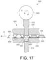
- FIG. 17illustrates one aspect of an assembling apparatus 900 employing a punch press arrangement for dispensing an electronic device from a carrier tape and compressing the electronic device with a powdered material into a tablet.
- the assembling apparatus 900comprises a tape and reel feed mechanism operatively coupled to a rotary punch press 420, previously discussed in connection with FIGS. 6-12 .
- the carrier tape 106is fed in direction B in between the die plate 506 and the punch portion 424 of the rotary punch press 420.
- the carrier tape 106indexes in direction B such that the electronic device 200 is axially centered with the die cavity 422, which contains a powdered material 550, which has been tamped or pre-compressed, and the upper and lower punches 512, 514.
- a cam 902actuates the upper punch 512 -- which acts as an ejector pin -- to perforate the carrier tape 106, forming apertures 906, 908 above and below the carrier tape 106, to dispense the electronic device 200 into the die cavity 422 above the pre-compressed powdered material 550.
- the cam 902rotates further in direction K, the upper punch 512 compresses the powdered material 550 and the electronic device 200 into a tablet form.
- the electronic device 200is dispensed and pressed into the tablet by actuating the upper punch 512 with the cam 902.
- FIG. 18illustrates one aspect of an assembling apparatus 1000 employing a punch press arrangement for dispensing an electronic device 200 from a carrier tape 1002 comprising first and second adhesive tapes 1004, 1006 and compressing the electronic device 200 with a powdered material into a tablet.
- the assembling apparatus 1000comprises a tape and reel feed mechanism operatively coupled to a rotary punch press 420, previously discussed in connection with FIGS. 6-12 .
- a carrier tape 1002comprises a first adhesive tape 1004 and a second adhesive tape 1006 with the electronic device 200 located therebetween.
- the first and second adhesive tapes 1004, 1006should have low mechanical strength but may be reinforced to facilitate reel handling.
- the first and second adhesive tapes 1004, 1006may be laminated to the carrier tape 1002.
- a roller 1008peels off the second adhesive tape 1006 to expose one side of the electronic device 200.
- the opposite side of the electronic device 200remains attached to the first adhesive tape 1004.
- the cam 902actuates the upper punch 512 to perforate the first adhesive tape 1004 forming apertures 1010 in the first adhesive tape 1004 to eject the electronic device 200 into the die cavity 422 above the powdered material 550, which has been tamped or pre-compressed.
- the upper punch 512compresses the powdered material 550 and the electronic device 200 into a tablet form.
- the electronic device 200is dispensed and pressed into the tablet by actuating the upper punch 512 with the cam 902.
- the upper punch 512 of the rotary punch press 420 used to cut through the carrier tape 1002can have the same diameter as the electronic device 200, for example.
- the first adhesive tape 1004should be made of a biocompatible material and the thickness of the first adhesive tape 1004 should be selected to minimize the appearance on the tablet.
- the first adhesive tape 1004may be made of a material that is fast dissolving in an aqueous solution.
- the adhesive tape 1004need not necessarily be soluble in an aqueous solution.
- the adhesive tape 1004 in contact with the electronic device 200can be porous to allow aqueous solution ingress.
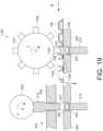
- FIG. 19illustrates one aspect of an assembling apparatus 1100 employing a rotating punch wheel 1102 comprising multiple punch heads 1104 for dispensing an electronic device 200 from a carrier tape 106, and a separate punch press process for compressing the electronic device 200 with a powdered material into a tablet.
- the assembling apparatus 1100comprises a tape and reel feed mechanism operatively coupled to a rotary punch press 420, previously discussed in connection with FIGS. 6-12 .
- the assembling apparatus 1100comprises a rotating punch wheel 1102 comprising multiple punch heads 1104.
- the punch wheel 1102rotates in direction L such that the punch head 1104 perforates the carrier tape 106, forming apertures 1106, 1108 above and below the carrier tape 106, to dispense the electronic device 200 into the die cavity 422 above the powdered material 550, which has been tamped or pre-compressed.
- the processcontinues to the punch portion 424 of the rotary punch press 420 to press the electronic device 200 into a tablet using the upper and lower pressing punches 512, 514.
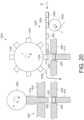
- FIG. 20illustrates one aspect of an assembling apparatus 1200 employing a rotating punch wheel 1102 comprising multiple punch heads 1104 for dispensing an electronic device 200 from a carrier tape 1002 comprising first and second adhesive tapes 1004, 1006 sandwiching an electronic device 200 therebetween, and a separate punch press process for compressing the electronic device 200 with a powdered material into a tablet.
- the assembling apparatus 1200comprises a tape and reel feed mechanism operatively coupled to a rotary punch press 420, previously discussed in connection with FIGS. 6-12 .
- the assembling apparatus 1200comprises a rotating punch wheel 1102 comprising multiple punch heads 1104.
- the carrier 1002comprises a first adhesive tape 1004 and a second adhesive tape 1006 with the electronic device 200 located therebetween, where the first and second adhesive tapes 1004, 1006 have low mechanical strength but may be reinforced to facilitate reel handling, as discussed in connection with FIG. 18 .
- the second adhesive tape 1006is peeled from the electronic device 200 and is rolled up by a roller 1008.
- the punch wheel 1102rotates in direction L such that the punch head 1104 perforates the first adhesive tape 1004, forming apertures 1206 in the first adhesive tape 1104, to dispense the electronic device 200 into the die cavity 422 above the powdered material 550, which has been tamped or pre-compressed.
- the processcontinues to the punch portion 424 of the rotary punch press 420 to press the electronic device 200 into a tablet using the upper and lower pressing punches 512, 514.
- FIG. 21illustrates one aspect of an assembling apparatus 1200 employing a rotary carrier wheel 1210 comprising a first punch station 1212 and rotary punch press 420 comprising a second punch station 1214 to dispense an electronic device 200 and compress the electronic device 200 with a powdered material into a tablet.
- the assembling apparatus 1200comprises a tape and reel feed mechanism 802 operatively coupled to a rotary punch press 420, previously discussed in connection with FIGS. 6-12 .
- the tape and reel feed mechanism 802does not include a rotary transfer mechanism using a rotary pick-and-place transfer mechanism as previously discussed herein.
- the tape and reel feed mechanism 802feeds the carrier tape 106 in direction B without removing the cover tape from the carrier tape 106.
- the carrier tape 106is positioned below a first punch station 1212 comprising an ejector pin 1202 as the rotary carrier wheel 1210 rotates in direction M.
- the rotary carrier wheel 1210can ride on a top surface of the rotary punch press 420 table for placement control.
- the ejector pin 1202 of the first punch station 1212punches the electronic device 200 through the carrier tape 106 package by perforating the carrier tape 106, leaving a perforation 806 or aperture, such that the electronic device 200 drops into a carrier assembly 1204 positioned below the ejector pin 804.
- the ejector pin 804is rotationally stationary and vertically movable by cam, solenoid, or other suitable actuation mechanism, without limitation.
- the carrier assembly 1204comprises an aperture 1206 to frictionally hold the electronic device 200 in place until the next transfer process step.
- the transfer wheel 1210rotates in direction M to the second punch station 1214 at the rotary punch press 420, which rotates in direction N, where a second ejector pin 1208 punches the electronic device 200 into the die cavity 422 of the rotary punch press 420, which has been pre filled with a powdered material 550, which has been tamped or pre-compressed.
- the second ejector pin 1208can provide pre-compression or tamping of the powdered material 550.
- the rotary punch press 420 and the punch portion 424operate in the same manner previously discussed in connection with FIGS. 6-12 to produce a tablet comprising the electronic device 200.
- the carrier assembly 1204may be configured to center the electronic component 200 to properly align the electronic device with the die cavity 422.
- the carrier assembly 1204may be configured to align the electronic device 200 with the center of the die cavity 422. This process may be assisted by vision guidance systems, pick-and-place tip designs, or other suitable mechanical configurations. Additional features include features formed on the electronic device 200 to enable suitable placement of the electronic device 200 relative to the die cavity 422.
- the electronic device 200can be handled with a vacuum pick-and-place machine can be employed to pick-up pre-punched electronic devices 200 from a waffle pack, tube, vibratory bowl, sheet, web strip, IDEC tray, carrier tape with adhered electronic device, among others.
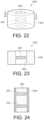
- FIG. 22illustrates one aspect of a carrier 1400 comprising an electronic device 200 embedded in a weighted annulus 1402, and FIG. 23 is a cross-sectional view taken along line 23-23.
- the weight and shape of the carrier 1400is compatible with core tablet press handlers that interface with the rotary punch press 420, as previously described.
- the carrier 1400defines a cavity 1404 for receiving the electronic device 200 therein.
- FIG. 24illustrates one aspect of a tube 1500 filled with a powdered material 550 and at least two electronic devices 200.
- the tube 1500is loaded with powdered material 550 and is then tamped or pre-compressed.
- the tube 1500is loaded with alternating layers of a pre-metered quantity of powdered material 550 and electronic devices 200.
- a press punchcompresses the powdered material 550 and the electronic devices 200 into tablet forms.
- any of the processes described hereinabove for manufacturing a tablet comprising an electronic devicemay be controlled using a variety of process controls.
- Such process controlsinclude, without limitation, monitoring for various process variables or parameters to ensure that a suitable amount of powdered material was or is dispensed into the die cavity and to also to determine that a single electronic device, or suitable number of electronic devices, is dispensed in the die cavity per tablet.
- Such process variables or parameters that can be monitored by a process control systeminclude, without limitation, weight of the dispended powdered material, weight of the electronic device, metal detection to detect the electronic device, wireless interrogation of the electronic device, tamp/compression force compression measurements, vision, X-rays, light/backlight/dark contrast, vertical placement, electrical, among others.
- any of the electronic device, powder filling, or tablet ejection operations described hereinabovemay be vision controlled, or controlled by other suitable process control means described herein.
- any of the operations described hereinabove for transferring the electronic device, powdered material, or tabletmay be performed using transfer wheels, conveyors, pick-and-place machines, hopper feed, gravity feed, mechanical feed, punch press, slide ramp, rotary wheel, vibratory bowl, among other suitable transfer mechanisms.
- any of such component transfer operationsmay be performed by a SCARA Cartesian robotic device, where SCARA is an acronym that stands for Selective Compliant Assembly Robot. It also may be referred to as a Selective Compliant Articulated Robot Arm.
- SCARA robotis a 4-axis robot arm that can move to any X-Y-Z coordinate within a predefined work envelope.
- a fourth axis of motionmay include wrist rotation (Theta-Z).
- the vertical motionis usually an independent linear axis at the wrist or in the base.
- the SCARA robot armincludes a parallel-axis joint layout with an arm that is slightly compliant in the X-Y direction but rigid in the "Z" direction making it selective compliant.
- a SCARA robotmay be configured to operate under controlling software that requires inverse kinematics for linear interpolated moves.
- accessing and handling of the electronic device 200may be performed using a variety of techniques including, without limitation, pick and place components, actuators, punch portion, peeled off tape, conveyor, gravity feed, air pressure, laser cuts, die ejection, among other techniques.
- Pick and place componentsinclude, without limitation, vacuum tools, adhesion, gripper.
- the electronic devices 200can be provided to a subsequent process, such as a rotary tablet press process, by a transfer wheel, conveyor, pick and place components, actuators, hopper, gravity feed, vibratory feed, punched into rotary tablet press, slide/ramp, or air pressure.
- any of the tape-and-reel feed mechanisms described hereinabovemay be configured to operate with a singles reel or with multiple reels.
- the reelmay be replaced with a web or sheet comprising one or more rows and columns of components, e.g., electronic devices, for dispensing and transferring into the die cavity for compression with a powdered material into a tablet.
- the electronic device 200includes tabs or legs 428 and electronics 426.
- the legs 428are flexible and as the electronic device 200 is pushed into the die cavity 422, the friction between the legs 428 and the wall of the die cavity 422 hold the electronic device 200 in place.
- the electronic device 200includes tabs or legs 430 and electronics 426.
- the legs 430are used to secure the electronic device 200 into the carrier 404.
- the carrier 404includes a matching number of slots or indentations 432 to the legs 430 of the electronic device 200.
- the number of legs 430may differ from the number of slots 432.
- the tabs 430engage the slots 432 and lock the electronic device 200 into place mechanically.
- the walls of the carrier 404change shape or collapse causing the electronic device 200 to be released from the carrier 404.
- a film layermay be manufactured via lamination, application of a coating solution, or slurry followed by a cure.
- the film or layermay be formed using dry compression, such as tablet press.
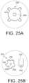
- the electronic device 200shown on a sheet 441, where the electronic device 200 includes a skirt 440 with a plurality of holes 444 and electronics 440.
- the sheets 442a and 442bare subject to heating or pressure, then the sheets 442a and 442b are secured to each other through the holes 444 and the electronic device 200 is securely held between the sheets 442a and 442b.
- the electronic device 200is laminated between the sheets 442a and 442b.
- the holes 444may be eliminated when the device is placed between the oversized portions and secured within a pocket that surrounds the electronic device 200.
- the electronic device 200may be punched out and placed inside a hole 462a of a transfer tray 462.
- the tray 462is shown in FIG. 28 with a plurality of holes. As shown in FIG. 29 , the tray 462 is positioned below a sheet of electronic devices 200.
- a punch blade 464cuts an electronic device 200 from the sheet of devices and inserts the electronic device 200 into the hole 462a.
- the electronic device 200is held in place in the hole 462 with friction as shown in Fig. 30 .
- the tray 462is then advanced to the next step of the process and a punch press 470 pushes the electronic device 200 into a die cavity 422 as shown in FIGS. 31 and 32 .
- FIG. 33illustrates one aspect of a logic flow diagram 1600 for a process of producing a tablet by compressing an electronic device with a powdered material.
- a powdered materialis provided into a die cavity.
- the powdered material in the die cavitytamped or pre-compressed.
- an electronic devicepreferably in the form of a semiconductor die, is inserted into the die cavity above the pre-compressed powdered material.
- the electronic deviceis compressed with the pre-compressed powdered material.
- an additional, over layer, of powdered materialis provided into the die cavity to form a tablet.
- the over layer of powdered materialis compressed.
- the pressed electronic device and powdered material in the form of a tabletis ejected from the die cavity.
- a machine vision inspection of the die cavitymay be performed after any one of the steps 1602-1614.
- the vision inspectioncan be useful to determine whether the powdered material and/or the die have been properly placed in the die cavity prior to tamping or compressing them into the final tablet product.
- other forms of inspectionmay be employed, such as, for example, without limitation, weight of the dispended powdered material, weight of the electronic device, metal detection to detect the electronic device, wireless interrogation of the electronic device, tamp/compression force compression measurements, X-rays, light/backlight/dark contrast, vertical placement, electrical, among others.
- the electronic device 200is an ingestible event marker (IEM) as illustrated and described in connection with FIG. 34 .
- IEMingestible event marker
- FIG. 34there is shown one aspect of an ingestible device event indicator system with dissimilar metals positioned on opposite ends as system 2030.
- the system 2030can be used in association with any pharmaceutical product, as mentioned above, to determine when a patient takes the pharmaceutical product.
- the scope of the present disclosureis not limited by the environment and the product that is used with the system 2030.
- the system 2030may be compressed into a tablet or placed within a capsule and the tablet or capsule is placed within the conducting liquid. The tablet or capsule would then dissolve over a period of time and release the system 2030 into the conducting liquid.
- the tablet or capsulewould contain the system 2030 and no product. Such a tablet or capsule may then be used in any environment where a conducting liquid is present and with any product. For example, the tablet or capsule may be dropped into a container filled with jet fuel, salt water, tomato sauce, motor oil, or any similar product. Additionally, the tablet or capsule containing the system 2030 may be ingested at the same time that any pharmaceutical product is ingested in order to record the occurrence of the event, such as when the product was taken.
- the system 2030is activated.
- the system 2030controls conductance to produce a unique current signature that is detected, thereby signifying that the pharmaceutical product has been taken.
- the system 2030includes a framework 2032.
- the framework 2032is a chassis for the system 2030 and multiple components are attached to, deposited upon, or secured to the framework 2032.
- a digestible material 2034is physically associated with the framework 2032.
- the material 2034may be chemically deposited on, evaporated onto, secured to, or built-up on the framework all of which may be referred to herein as "deposit" with respect to the framework 2032.
- the material 2034is deposited on one side of the framework 2032.
- the materials of interest that can be used as material 2034include, but are not limited to: Cu or CuI.
- the material 2034is deposited by physical vapor deposition, electrodeposition, or plasma deposition, among other protocols.
- the material 2034may be from about 0.05 to about 500 ⁇ m thick, such as from about 5 to about 100 ⁇ m thick.
- the shapeis controlled by shadow mask deposition, or photolithography and etching. Additionally, even though only one region is shown for depositing the material, each system 2030 may contain two or more electrically unique regions where the material 2034 may be deposited, as desired.
- Another digestible material 2036is deposited, such that materials 2034 and 2036 are dissimilar.
- the different side selectedmay be the side next to the side selected for the material 2034.
- the scope of the present disclosureis not limited by the side selected and the term "different side" can mean any of the multiple sides that are different from the first selected side.
- the shape of the systemis shown as a square, the shape maybe any geometrically suitable shape.
- Material 2034 and 2036are selected such that they produce a voltage potential difference when the system 2030 is in contact with conducting liquid, such as body fluids.
- the materials of interest for material 2036include, but are not limited to: Mg, Zn, or other electronegative metals.
- the material 2036may be chemically deposited on, evaporated onto, secured to, or built-up on the framework. Also, an adhesion layer may be necessary to help the material 2036 (as well as material 2034 when needed) to adhere to the framework 2032. Typical adhesion layers for the material 2036 are Ti, TiW, Cr or similar material. Anode material and the adhesion layer may be deposited by physical vapor deposition, electrodeposition or plasma deposition. The material 2036 may be from about 0.05 to about 500 ⁇ m thick, such as from about 5 to about 100 ⁇ m thick. However, the scope of the present disclosure is not limited by the thickness of any of the materials nor by the type of process used to deposit or secure the materials to the framework 2032.
- a current pathis formed through the conducting liquid between material 2034 and 2036.
- a control device 2038is secured to the framework 2032 and electrically coupled to the materials 2034 and 2036.
- the control device 2038includes electronic circuitry, for example control logic that is capable of controlling and altering the conductance between the materials 2034 and 2036.
- the voltage potential created between the materials 2034 and 2036provides the power for operating the system as well as produces the current flow through the conducting fluid and the system.
- the systemoperates in direct current mode.
- the systemcontrols the direction of the current so that the direction of current is reversed in a cyclic manner, similar to alternating current.
- the path for current flow between the materials 2034 and 2036is completed external to the system 2030; the current path through the system 2030 is controlled by the control device 2038. Completion of the current path allows for the current to flow and in turn a receiver, not shown, can detect the presence of the current and recognize that the system 2030 has been activate and the desired event is occurring or has occurred.
- the two materials 2034 and 2036are similar in function to the two electrodes needed for a direct current power source, such as a battery.
- the conducting liquidacts as the electrolyte needed to complete the power source.
- the completed power source describedis defined by the physical chemical reaction between the materials 2034 and 2036 of the system 2030 and the surrounding fluids of the body.
- the completed power sourcemay be viewed as a power source that exploits reverse electrolysis in an ionic or a conductive solution such as gastric fluid, blood, or other bodily fluids and some tissues.
- the environmentmay be something other than a body and the liquid may be any conducting liquid.
- the conducting fluidmay be salt water or a metallic based paint.
- these two materialsare shielded from the surrounding environment by an additional layer of material. Accordingly, when the shield is dissolved and the two dissimilar materials are exposed to the target site, a voltage potential is generated.
- the materials 2034 and 2036provide the voltage potential to activate the control device 2038.
- the control device 2038can alter conductance between the materials 2034 and 2036 in a unique manner.
- the control device 2038is capable of controlling the magnitude of the current through the conducting liquid that surrounds the system 2030. This produces a unique current signature that can be detected and measured by a receiver (not shown), which can be positioned internal or external to the body.
- non-conducting materials, membrane, or “skirt”are used to increase the "length" of the current path and, hence, act to boost the conductance path, as disclosed in the U.S. patent application Ser. No. 12/238,345 entitled, "In-Body Device with Virtual Dipole Signal Amplification” filed Sep. 25, 2008 .
- the terms “non-conducting material”, “membrane”, and “skirt”are interchangeably with the term “current path extender” without impacting the scope or the present aspects and the claims herein.
- the skirtshown in portion at 2035 and 2037, respectively, may be associated with, e.g., secured to, the framework 2032.
- the system 2030may be surrounded entirely or partially by the skirt and the skirt maybe positioned along a central axis of the system 2030 or off-center relative to a central axis.
- the scope of the present disclosureis not limited by the shape or size of the skirt.
- the materials 2034 and 2036may be separated by one skirt that is positioned in any defined region between the materials 2034 and 2036.
- the system 2040includes a framework 2042.
- the framework 2042is similar to the framework 2032 of FIG. 34 .
- a digestible or dissolvable material 2044is deposited on a portion of one side of the framework 2042.
- another digestible material 2046is deposited, such that materials 2044 and 2046 are dissimilar. More specifically, material 2044 and 2046 are selected such that they form a voltage potential difference when in contact with a conducting liquid, such as body fluids.
- a current pathis formed through the conducting liquid between material 2044 and 2046.
- a control device 2048is secured to the framework 2042 and electrically coupled to the materials 2044 and 2046.
- the control device 2048includes electronic circuitry that is capable of controlling part of the conductance path between the materials 2044 and 2046.
- the materials 2044 and 2046are separated by a non-conducting skirt 2049.
- Various examples of the skirt 2049are disclosed in U.S. Provisional Application No. 61/173,511 filed on Apr.
- control device 2048can alter conductance between the materials 2044 and 2046.
- the control device 2048is capable of controlling the magnitude of the current through the conducting liquid that surrounds the system 2040.
- a unique current signature that is associated with the system 2040can be detected by a receiver (not shown) to mark the activation of the system 2040.
- the size of the skirt 2049is altered. The longer the current path, the easier it may be for the receiver to detect the current.
- the system 2030 of FIG. 34is shown in an activated state and in contact with conducting liquid.
- the system 2030is grounded through ground contact 2052.
- the system 2030also includes a sensor module 2074, which is described in greater detail with respect to FIG. 39 ion or current paths 2050 form between material 2034 to material 2036 through the conducting fluid in contact with the system 2030.
- the voltage potential created between the material 2034 and 2036is created through chemical reactions between materials 2034/2036 and the conducting fluid.
- FIG. 37shows an exploded view of the surface of the material 2034.
- the surface of the material 2034is not planar, but rather an irregular surface 2054 as shown.
- the irregular surface 2054increases the surface area of the material and, hence, the area that comes in contact with the conducting fluid.
- the material 2034there is chemical reaction between the material 2034 and the surrounding conducting fluid such that mass is released into the conducting fluid.
- the term "mass” as used hereinrefers to protons and neutrons that form a substance.
- One exampleincludes the instant where the material is CuCI and when in contact with the conducting fluid, CuCI becomes Cu (solid) and Cl - in solution. The flow of ions into the conduction fluid is depicted by the ion paths 2050.
- the rate of ionic exchange and, hence the ionic emission rate or flow,is controlled by the control device 2038.
- the control device 2038can increase or decrease the rate of ion flow by altering the conductance, which alters the impedance, between the materials 2034 and 2036.
- the system 2030can encode information in the ionic exchange process.
- the system 2030uses ionic emission to encode information in the ionic exchange.
- the control device 2038can vary the duration of a fixed ionic exchange rate or current flow magnitude while keeping the rate or magnitude near constant, similar to when the frequency is modulated and the amplitude is constant. Also, the control device 2038 can vary the level of the ionic exchange rate or the magnitude of the current flow while keeping the duration near constant. Thus, using various combinations of changes in duration and altering the rate or magnitude, the control device 2038 encodes information in the current flow or the ionic exchange. For example, the control device 2038 may use, but is not limited to any of the following techniques namely, Binary Phase-Shift Keying (PSK), Frequency modulation, Amplitude modulation, on-off keying, and PSK with on-off keying.
- PSKBinary Phase-Shift Keying
- the various aspects disclosed hereininclude electronic components as part of the control device 2038 or the control device 2048.
- Components that may be presentinclude but are not limited to: logic and/or memory elements, an integrated circuit, an inductor, a resistor, and sensors for measuring various parameters.
- Each componentmay be secured to the framework and/or to another component.
- the components on the surface of the supportmay be laid out in any convenient configuration. Where two or more components are present on the surface of the solid support, interconnects may be provided.
- the systemsuch as system 2030 and 2040, control the conductance between the dissimilar materials and, hence, the rate of ionic exchange or the current flow.
- the systemis capable of encoding information in the ionic exchange and the current signature.
- the ionic exchange or the current signatureis used to uniquely identify the specific system.
- the systems 2030 and 2040are capable of producing various different unique exchanges or signatures and, thus, provide additional information.
- a second current signature based on a second conductance alteration patternmay be used to provide additional information, which information may be related to the physical environment.
- a first current signaturemay be a very low current state that maintains an oscillator on the chip and a second current signature may be a current state at least a factor of ten higher than the current state associated with the first current signature.
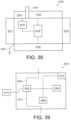
- the device 2030includes a control module 2062, a counter or clock 2064, and a memory 2066. Additionally, the device 2038 is shown to include a sensor module 2072 as well as the sensor module 2074, which was referenced in FIG. 36 .
- the control module 2062has an input 2068 electrically coupled to the material 2034 and an output 2070 electrically coupled to the material 2036.
- the control module 2062, the clock 2064, the memory 2066, and the sensor modules 2072/2074also have power inputs (some not shown). The power for each of these components is supplied by the voltage potential produced by the chemical reaction between materials 2034 and 2036 and the conducting fluid, when the system 2030 is in contact with the conducting fluid.
- the control module 2062controls the conductance through logic that alters the overall impedance of the system 2030.
- the control module 2062is electrically coupled to the clock 2064.
- the clock 2064provides a clock cycle to the control module 2062. Based upon the programmed characteristics of the control module 2062, when a set number of clock cycles have passed, the control module 2062 alters the conductance characteristics between materials 2034 and 2036. This cycle is repeated and thereby the control device 2038 produces a unique current signature characteristic.
- the control module 2062is also electrically coupled to the memory 2066. Both the clock 2064 and the memory 2066 are powered by the voltage potential created between the materials 2034 and 2036.
- the control module 2062is also electrically coupled to and in communication with the sensor modules 2072 and 2074.
- the sensor module 2072is part of the control device 2038 and the sensor module 2074 is a separate component.
- either one of the sensor modules 2072 and 2074can be used without the other and the scope of the present disclosure is not limited by the structural or functional location of the sensor modules 2072 or 2074.
- any component of the system 2030may be functionally or structurally moved, combined, or repositioned without limiting the scope of the present disclosure.
- the sensor modules 2072 or 2074can include any of the following sensors: temperature, pressure, pH level, and conductivity.
- the sensor modules 2072 or 2074gather information from the environment and communicate the analog information to the control module 2062.
- the control modulethen converts the analog information to digital information and the digital information is encoded in the current flow or the rate of the transfer of mass that produces the ionic flow.
- the sensor modules 2072 or 2074gather information from the environment and convert the analog information to digital information and then communicate the digital information to control module 2062.
- the sensor modules 2074is shown as being electrically coupled to the material 2034 and 2036 as well as the control device 2038.
- the sensor module 2074is electrically coupled to the control device 2038 at connection 2078.
- the connection 2078acts as both a source for power supply to the sensor module 2074 and a communication channel between the sensor module 2074 and the control device 2038.
- the system 2030includes a pH sensor module 2076 connected to a material 2039, which is selected in accordance with the specific type of sensing function being performed.
- the pH sensor module 2076is also connected to the control device 2038.
- the material 2039is electrically isolated from the material 2034 by a non-conductive barrier 2055.
- the material 2039is platinum.
- the pH sensor module 2076uses the voltage potential difference between the materials 2034/2036.
- the pH sensor module 2076measures the voltage potential difference between the material 2034 and the material 2039 and records that value for later comparison.
- the pH sensor module 2076also measures the voltage potential difference between the material 2039 and the material 2036 and records that value for later comparison.
- the pH sensor module 2076calculates the pH level of the surrounding environment using the voltage potential values.
- the pH sensor module 2076provides that information to the control device 2038.
- the control device 2038varies the rate of the transfer of mass that produces the ionic transfer and the current flow to encode the information relevant to the pH level in the ionic transfer, which can be detected by a receiver (not shown).
- the system 2030can determine and provide the information related to the pH level to a source external to the environment.
- control device 2038can be programmed in advance to output a pre-defined current signature.
- systemcan include a receiver system that can receive programming information when the system is activated.
- switch 2064 and the memory 2066can be combined into one device.
- the system 2030may also include one or other electronic components.
- Electrical components of interestinclude, but are not limited to: additional logic and/or memory elements, e.g., in the form of an integrated circuit; a power regulation device, e.g., battery, fuel cell or capacitor; a sensor, a stimulator, etc.; a signal transmission element, e.g., in the form of an antenna, electrode, coil, etc.; a passive element, e.g., an inductor, resistor, etc.
- the techniques described hereinprovide bonding of a skirt material and or/sensor surface to the tablet powdered material blend or granulation during compression of tablets or the placement of an electronic device such as an IEM in the tablet press for sensor-in-tablet platform.
- texture or featuresmay be added to the skirt film during manufacturing of the film, during manufacturing of the IEM, or after manufacturing the IEM.
- the texturemay be created by mechanical deformation of the skirt, laser texturing of the skirt, chemical etch, or by making the formulation more porous, or by thermal processing.
- macroscale featuresmay be created such as holes, slots, indentations, or other shapes to provide tablet bonding or riveting to the IEM.
- an adhesivemay be added to the skirt, or otherwise the skirt may be made sticky to enhance bonding of the tablet material to the IEM.
- FIGS. 40 and 41illustrate one aspect of a pick-and-place transfer mechanism 2100 for picking an electronic device 200 from a cavity 108 of a carrier tape 106 and transferring the electronic device 200.
- the pick-and-place transfer mechanism 2100comprises a housing 2102 that defines a chamber 2120 to contain a movable pressure plate 2104 and a movable prong holder plate 2106.
- the pressure plate 2104is movable in a downward direction to pick an electronic device 200 comprising a skirt 2110 by the application of a force F D , which also compresses a spring 2108.
- the spring 2108stores energy and applies an upward force F U to lift the electronic device 200 from the cavity 108 of the carrier tape 106.
- the downward force F Dmay be applied mechanically by a piston 2112 (as shown) or by pressurized air acting against the pressure plate 2104. If the downward force F D is applied by the piston 212, the spring force F C may be used as the lifting force. If the downward force F D is applied by pressurized air, then the application of a vacuum may be employed to lift the pressure plate 2104.
- prongs 2114Attached to the pressure plate 2104 are a plurality of prongs 2114 (arms), which are elongated members employed to engage the outer diameter 2116 (perimeter) of the skirt 2110 portion of the electronic device 200 in order to lift the electronic device 200 out of the cavity 108.
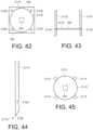
- four prongs 2114are employed to grasp the outer diameter 2116 of the skirt 2110 surrounding the electronic device 200. This is best illustrated in FIG. 45 , which illustrates a bottom view perspective of the four prongs 2114 engaging the outer diameter 2116 of the skirt 2110 portion of the electronic device 200.
- the four prongs 2114are slidably disposed within corresponding apertures formed in prong holder 2106.
- the prong holder 2106is configured such that the distal ends 2118 of the prongs 2114 expand slightly as indicted by the arrows in order to facilitate engagement of the perimeter of the skirt 2110.
- the spring loaded chamber 2120may comprise a vacuum opening 2122 on a side to add vacuum to assist with lifting and holding the electronic device 200.
- FIG. 42is a top view of the electronic device 200 located within the cavity 108 of the carrier tape 106.
- the electronic device 200sits in a square surface mount technology (SMT) carrier tape 106 pocket or cavity 106, which leaves the four corners 2128 open and available to receive the distal ends 2118 of the prongs 2114.
- SMTsquare surface mount technology
- the prongs 2114are attached to a spring loaded (or air actuated) chamber 2120 that expands the prongs 2114 to fit into the four corners 2128 of the carrier tape cavity 108 pocket, and then retracts and tightens the prongs 2114 around the outer diameter 2116 of the skirt 2110 portion of the electronic device 2110 as shown in FIG. 45 , from a bottom view perspective, and FIG. 43 from a side view perspective.
- the distal end 2118 of each prong 2114comprises feature to assist locating and grasping the electronic device 200.
- a indent 2124 feature located near the distal end 2118 of the prong 2114will assist to secure the electronic device 200 into place.
- the tip portion of the prong 2114comprises a slight chamfer 2126 to help slide the prong 2114 corners 2128 inside the cavity 108 portion of the carrier tape 106.
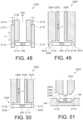
- FIGS. 46Ais a cross-sectional view of one aspect of an example of a pick-and-place tool 2150 holding an electronic device 200 within a mechanical gripper 2154.
- FIG. 46Bis a bottom view of the pick-and-place tool 2150 holding an electronic device 200 shown in FIG. 46A .
- a vacuum tube 2152 pick toolis located within a chamber 2158 defined by a mechanical gripper 2154.
- the pick-and-place tool 2150may comprise a plurality of mechanical grippers 2154 comprising a flange 2156 portion for grasping and holding the outer diameter 2116 portion of the skirt 2110 portion of the electronic device 200. As illustrated in FIG.
- the pick-and-place tool 2150may comprise four mechanical grippers 2154 each comprising a flange 2156 portion for clamping or grasping and holding the electronic 200 by the outer diameter 2116 of the skirt 2110.
- the mechanical gripper 2154is sued to clamp around the outer diameter 2116 of the skirt 2110 portion of the electronic device 200.
- the distal ends 2160 of the mechanical gripper 2154spread open when the pick-and-place tool 2150 is extended, but when the retracted, the mechanical gripper 2154 closes around the outer diameter 2116 of the skirt 2110 portion of the electronic device 200 and centers the electronic device 200 relative to the vacuum tube 2152 pick tip.
- FIG. 47illustrates one aspect of a friction hold disc mechanism 2170 for handling an electronic device 200.
- An electronic device 200is initially contained within a tape carrier 2172.
- a cam driven pin 2174 movable in direction Vis used to push the electronic device 200 from the carrier tape 2172 into a cavity 2180 of a rotating disc 2176.
- the electronic device 200is pushed or placed in the cavity 2180 of the rotating disc 2176 and is then centered over a carrier 2178 before being pushed into the carrier 2178 by the vertically V cam driven pin 2174.
- FIG. 48illustrates an example of a pick-and-place tool 2170 comprising a mobile sleeve 2172.
- the pick-and-place tool 2170comprises mobile sleeve 2172 that is capable of moving up-and-down in a direction V.
- the mobile sleeve 2172is spring 2174 loaded.
- the mobile sleeve 2172is used to center the electronic device 200 relative to a vacuum tube 2152 pick tool is located within the mobile sleeve 2172.
- FIG. 49illustrates an example of a pick-and-place tool 2200 in accordance with the invention, comprising an internal ejection member 2202 (plunger) and a vacuum tube 2204.
- the ejection member 2202is movable in direction V within an inner chamber 2206 defined by the vacuum tube 2204.
- the distal end 2208 of the vacuum tube 2204is shaped to center the electronic device 200 with the ejection member 2202.
- the distal end 2208 of the vacuum tube 2204comprises tapered edges 2210 to slidably receive and center the electronic device 200 relative to the ejection member 2202.
- the electronic device 200is picked when a vacuum is applied to the vacuum tube 2204.
- the ejection member 2202may be spring loaded, or otherwise movable, to push out the electronic device 200 once the vacuum is removed for placement.
- FIG. 50illustrates an example of pick-and-place tool 2220 comprising an internal ejection member 2222 (plunger) and an external tube 2224 comprising needles 2230 located at a distal end of the external tube 2224.
- the needles 2230puncture the skirt 2210 portion of the electronic device 200.
- the ejection tube 2222is movable in direction V within an inner chamber 2226 defined by the external tube 2224.
- the ejection tube 2222can be mechanically pushed to eject the electronic device 200 from the needles 2230 when the placed over a desired location.
- the ejection tube 2222may be spring loaded or cam driven without the need of a vacuum source for picking and/or placing the electronic device.
- FIG. 51illustrates an example of pick-and-place tool 2240 comprising a head 2242 that has an external profile that matches the internal cavity profile of the carrier tape.
- the distal end 2246 of the head 2242comprises a tapered outer wall 2244 where the profile of the tapered outer wall 2244 complements (or matches) the internal profile 2248 of the carrier tape 106 cavity 108.
- the distal end 2246 of the head 2242is inserted within the cavity 108 of the carrier tape 108
- the distal end 2246 of the head 2242is centered with the electronic device 200.
- the shape of the tapered outer wall 2244forces the electronic device 200 to be centered with a complementary shaped inner cavity during placement.
- FIG. 52illustrates an example of a pick-and-place tool 2260 comprising an inner slot 2266 at a distal end 2272 of a gripper 2268.
- the pick-and-place tool 2260comprises an outer gripper 2268 with an inner slot 2266 defined at a distal end 2272 of the gripper 2268.
- a punch 2274 that is movable in direction Vis used to push the electronic device 200 into a chamber 2276 defined within the distal end 2272 of the gripper 2268.
- the outer diameter 2116 of the skirt 2110 portion of the electronic device 200flexes and snaps in and out of the slot 2266 within the chamber 2276.
- An ejection member 2264that is movable in direction V is used to eject the electronic device 200 when it is time for placement.
- FIG. 53illustrates an example of a pick-and-place tool 2280 comprising an inner slot 2286 at a distal end 2292 of a gripper 2282.
- the pick-and-place tool 2280comprises an outer gripper 2282 with an inner slot 2286 defined by snap elements 2294 located at the distal end 2292 of the gripper 2282.
- the pick-and-place tool 2280is plunged in a downward direction to snap the outer diameter 2116 of the skirt 2110 portion of the electronic device 200 such that it is snapped into the chamber 2290.
- the outer diameter 2116 of the skirt 2110 portion of the electronic device 200flexes and snaps in and out of the chamber 2290 and is held in place by the vertical seat defined by the snap elements 2294.
- An ejection member 2284that is movable in direction V is used to eject the electronic device 200 when it is time for placement.
- FIG. 54illustrates one embodiment of a pick-and-place tool 2300 comprising features 2304 at a distal end 2310 to create notches around the outer diameter 2116 of the skirt 2110 portion of the electronic device 200.
- the pick-and-place tool 2300comprises a movable body portion 2302 and notching features 2304 at the distal end.
- the notching features 2304pinch the edges of the skirt material 2308 to create notches in the skirt portion 2110 of the electronic device 200 for frictional holding in a carrier.
- the cutout 2306 portion below the tool 2300shows the features formed in the skirt 2110 portion of the electronic device 200. Since the notched edges hold the electronic device 200 in a carrier or cavity by friction, the electronic device 200 forced out by a plunger, similar to the ejection members described previously.
- FIG. 55illustrates an example of pick-and-place tool 2320 configured with hook-and-loop (VELCRO) or ridges 2330 at a distal end 2332 to hold the electronic device 200 in place.
- the pick-and-place tool 2320comprises an outer body 2322 portion defining an inner chamber 2326 for movably receiving therein an ejection member 2324 (plunger) that is movable in direction V.
- a distal end 2332 of the pick-and-place tool 2320comprises hook-and-loop (VELCRO) or ridges 2330 at a distal end 2332 to hold the electronic device 200.
- the ejection tool 2324 or plungeris used to force out or eject the electronic device when it is time for placement.
- FIG. 56illustrates one aspect of a tower 2340 for storing electronic devices 200.
- the tower 2340comprises a cylindrical body 2342 defining an inner chamber 2348 suitable for storing electronic devices 200.
- the cylindrical body 2342comprises seats 2344 or ledges to holding the electronic devices 200 within the chamber 2348.
- Electronic devices 200are located below the tower body 2342 in the usual carrier tape 106.
- a punch 2346 movable in direction Vis used to punch through the carrier tape 106 and load the electronic device 200 into the camber 2348.
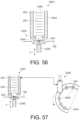
- FIG. 57illustrates one aspect of the tower 2340 interfaced with a rotary transfer plate 2354.
- the tower 2340may be flipped upside down to dispense the electronic devices 200 into nests 2352 located on the rotary transfer plate 2354.
- FIG. 58illustrates an example a transfer mechanism 2400 employing a vacuum plate 2402 for holding electronic devices 200 until they are ready to be dispensed.
- the electronic devices 200are moving along the in the carrier tape 106.
- the cover tape 110is removed such that the vacuum plate 2402 applies negative pressure to the top side of the electronic device 200 to hold the electronic device 200 in place until ready for dispensing on a conveyor 2404, as shown, or a carrier.
- FIG. 59illustrates an example of a transfer mechanism 2450 that employs a vacuum plate 2402 for holding electronic devices 200 until they are ready to be dispensed.
- the electronic devices 200are supplied by way of the carrier tape 106.
- the cover tape 110is removed at a stripping station 2458 just prior to the vacuum plate 2402 such that when the cover tape 110 is removed, the negative pressure from the vacuum plate is applied to the top portion of the electronic device 200 to hold the electronic device in place until it is time to dispense.
- an insert pin 2452pushes out the electronic device 200 into a die cavity 2454 located on the tablet top plate 2456.
- a bottom punch 2458is used to form the electronic device 200 into a tablet using the die cavity 2454.
- FIG. 60illustrates an example of a transfer mechanism that employs a vacuum plate 2402 for holding electronic devices 200 until they are ready to be dispensed.
- the electronic devices 200are supplied by way of the carrier tape 106.
- the cover tape 110is removed at a stripping station 2458 by a stripping edge 2455 just prior to the vacuum plate 2402 such that when the cover tape 110 is removed, the negative pressure from the vacuum plate is applied to the top portion of the electronic device 200 to hold the electronic device in place until it is time to dispense.
- an insert pin 2468pushes out the electronic device 200 into a die cavity 2462 located on the tablet top plate 2464.
- the insert pin 2468moves through the carrier tape 106 to push the electronic device 200 into the die cavity 2462.
- the insert pin 2468 activationcan be linear motion.
- FIG. 61illustrates one aspect of a transfer mechanism 2470 employing a rail feed 2472 to supply the electronic devices 200 top the tablet process table top 2476.
- the electronic devices 200are supplied to the punch station 2482 above the punch die cavity 2474 by way of the rail feed 2472.
- a linear actuator 2480 having electronic device 200 alignment pins 2478is used to transfer the electronic device 100 into the die cavity 2474.
- the electronic devices 200are forced down the rail feed 2472 into insert position.
- the linear actuator 2480aligns the electronic device 200 with four pins 2478 and then applies a force F to the electronic device 200 to bend or flex the skirt 2110 portion of the electronic device 200 slightly out of the opening 2484 beneath the rail feed 2472 and in to the die cavity 2474.
- the linear actuator 2480dispense the electronic devices 200 into carriers or nests located on the process table top 2476.
- FIG. 62illustrates a cross sectional view of an example of an ejection mechanism 2500 that rotates eccentrically about a first axis 2508.
- the ejection mechanism 2500comprises vacuum tubes 2506 and ejector members 2502 therebetween.
- the ejector members 2502are rotatably attached to a wheel 2504 that rotates eccentrically such that the ejector members 2502 act on the electronic device.
- FIG. 63illustrates a side view of the example of the ejection mechanism 2500 shown in FIG. 62 .
- the wheel 2504rotates about the axis 2508, which causes the ejector members 2502 to move accordingly.
- a second wheel attached to the vacuum tubes 2506(not shown) rotates about a center axis 2510.
- FIG. 64illustrates a cross sectional view of the example of the ejection mechanism 2500 shown in FIGS. 62 and 63 .
- the vacuum tubes 2506hold the electronic device 200 place.
- the ejector members 2502are coupled to a first wheel 2504 that rotates eccentrically about the axis 2508.
- the vacuum tubes 2506 for holding the electronic device 200are coupled to a second wheel 2512 that rotates on center about axis 2510.
- the offset ejector member 2502ejects the electronic device 200 out into the cavity.
- FIG. 65illustrates a pick-and-place tool 2600 comprising a body 2602 and flexible (resilient) fingers or flaps 2604 to grasp and hold the electronic device 200.
- the resilient fingers 2604may be made of rubber or other suitable material.
- FIG. 66illustrates one aspect of a transfer mechanism 2610 that employs gravity.
- the transfer mechanism 2610uses of gravity and a plated template 2612 to allow an electronic device 200 to fall into the press 2614 and center it as it falls thru the template.
- FIG. 67illustrates one aspect of a transfer mechanism 2620 that employs air pressure.
- the transfer mechanism 2620uses air pressure 2622 from the bottom of the carrier tape 106 to push the electronic device 200 out of the carrier tape 106 through a pressurized feeder tube 2624 which ejects the electronic device 200 into the press 2614.
- FIG. 68illustrates an example of a transfer mechanism 2630 that employs a vacuum feeder.
- the transfer mechanism 2630uses a vacuum feeder wheel 2632 that holds the electronic devices 200 by a vacuum tube and the wheel spins and places the electronic device 200 in the press 2614.
- the vacuum feeder 2634has an array of vacuum heads.
- FIG. 69illustrates one aspect of collet gripper 2640 having a body 2642 that expands during the grip process, then contracts on the electronic device 200 forming positive pressure grip around the outside of the electronic device 200.
- the mechanism to open and close the collett gripper head 2644can be cam driven (pointy arrow in middle).
- FIG. 70illustrates one aspect of a transfer mechanism 2650 comprising a pre punched film/carrier tape 2652 that holds the electronic device 200 so that punching the electronic device 200 out into the press tool 2654 with a punch 2656 can be facilitated. This would also facilitate unique perimeter designs mentioned previously.
- FIG. 71illustrates one aspect of a transfer mechanism 2660 as shown in FIG. 70 except that the punch occurs into a rotating plate 2664 that may hold the electronic device 200 with a friction fit around the perimeter, or have some mechanical feature to lock in place. This rotating plate can move the electronic device 200 into the press area.
- FIG. 72illustrates a transfer mechanism 2670 comprising electrically charged pick-up head with fingers 2672, 2674 having opposite charge to grab the electronic device and hold the electronic device 200 in place by electrostatic forces.
- any reference to “one aspect” or “an aspect”means that a particular feature, structure, or characteristic described in connection with the aspect is included in at least one aspect.
- appearances of the phrases “in one aspect” or “in an aspect” in various places throughout the specificationare not necessarily all referring to the same aspect.
- the particular features, structures or characteristicsmay be combined in any suitable manner in one or more aspects.
- Coupledand “connected” along with their derivatives. It should be understood that these terms are not intended as synonyms for each other. For example, some aspects may be described using the term “connected” to indicate that two or more elements are in direct physical or electrical contact with each other. In another example, some aspects may be described using the term “coupled” to indicate that two or more elements are in direct physical or electrical contact. The term “coupled,” however, also may mean that two or more elements are not in direct contact with each other, but yet still co-operate or interact with each other.
Landscapes
- Health & Medical Sciences (AREA)
- Life Sciences & Earth Sciences (AREA)
- Engineering & Computer Science (AREA)
- Mechanical Engineering (AREA)
- Public Health (AREA)
- Veterinary Medicine (AREA)
- Animal Behavior & Ethology (AREA)
- General Health & Medical Sciences (AREA)
- Physics & Mathematics (AREA)
- Molecular Biology (AREA)
- Heart & Thoracic Surgery (AREA)
- Surgery (AREA)
- Medical Informatics (AREA)
- Biophysics (AREA)
- Pathology (AREA)
- Biomedical Technology (AREA)
- Chemical & Material Sciences (AREA)
- Pharmacology & Pharmacy (AREA)
- Medicinal Chemistry (AREA)
- Optics & Photonics (AREA)
- Packages (AREA)
- Control And Other Processes For Unpacking Of Materials (AREA)
- Medical Preparation Storing Or Oral Administration Devices (AREA)
- Medicinal Preparation (AREA)
- Containers And Plastic Fillers For Packaging (AREA)
- Formation And Processing Of Food Products (AREA)
Description
- Various embodiments are disclosed that relate to manufacturing electronic devices with partial power sources and, more specifically, to electronic devices secured to a tablet wherein the electronic devices are activated upon contact with a conducting fluid.
- Pharmaceutical products are delivered to a user in many forms, including a pill. Integration of a pharmaceutical product with an ingestible device into a tablet is often a challenge due to the delicate nature of the electronic components as well as the difficulty in securing the electronic components to the pharmaceutical product, such as a pill, tablet, capsule. For example, tablets are typically made using a press that applies pressure to a powder form. Handling a small electronic device is often a challenge during the assembly process. Therefore, what is needed is a technique for handling a small ingestible electronic device and attaching the device to a pharmaceutical product such as a tablet without damaging the ingestible electronic device. Patent publications
US 2012/011699 A1 ,EP 0 981 152 A2US 5 310 301 A discuss information usefull for the understanding of the background of the present invention. The documentUS 2012/011699 A1 discloses a method of manufacturing a tablet comprising an electronic device, and a system in accordance with the preamble ofclaim 6. - Accordingly, the present invention is directed to a method of manufacturing a tablet comprising an electronic device according to
claim 1. - The present invention is further directed to a system for manufacturing a tablet comprising an electronic device according to
claim 6. FIG. 1 is a perspective view of one aspect of a tape and reel assemblage for storing electronic devices.FIG. 2 is an illustration of one aspect of a carrier tape with the cover tape removed to show an electronic device located within each of the cavities of the carrier tape.FIG. 3 is a side view of one aspect of a carrier tape comprising a cover tape and an electronic device located within each of the cavities of the carrier tape.FIG. 4 is a side view of one aspect of a carrier tape showing one cavity with the cover tape located over the cavity to secure the electronic device located within each of the cavities and one cavity with the cover tape removed to expose the electronic device for removal from the carrier tape.FIG. 5 illustrates a schematic of one aspect of a tape and reel feed mechanism with areel 100 having a hub, a carrier tape with cavities, and a cover tape.FIG. 6 illustrates one aspect of an assembling apparatus for compressing an electronic device with a powdered material into a tablet.FIG. 7 is a perspective view of one aspect of a portion of one aspect of a rotor of the rotary tablet press shown inFIG. 6 .FIG. 8 shows a section through the arrangement according toFIG. 7 , along the line 8-8.FIG. 9 shows an exploded perspective view of one aspect of a lower upper punch with guiding sleeve and sealing rings.FIG. 10 shows a perspective view of one aspect of an assembly of the upper stamp with sleeve and sealing rings according toFIG. 9 .FIG. 11 shows different cross sections for the punch shafts.FIG. 12 is a diagram of one aspect of a suction (vacuum) pick-and-place element transferring an electronic device in a die cavity of a die plate.FIG. 13 illustrates one aspect of a low profile carrier tablet for use with a tablet press, such as the rotary punch press.FIG. 14 illustrates one aspect an electronic device comprising materials and a base material for increased thickness.FIG. 15 illustrates one aspect of an assembling apparatus for compressing an electronic device with a powdered material into a tablet.FIG. 16 illustrates one aspect of an assembling apparatus employing a punch station to dispense an electronic device and compress the electronic device with a powdered material into a tablet.FIG. 17 illustrates one aspect of an assembling apparatus employing a punch press arrangement for dispensing an electronic device from a carrier tape and compressing the electronic device with a powdered material into a tablet.FIG. 18 illustrates one aspect of an assembling apparatus employing a punch press arrangement for dispensing an electronic device from a carrier tape comprising first and second adhesive tapes and compressing the electronic device with a powdered material into a tablet.FIG. 19 illustrates one aspect of an assembling apparatus employing a rotating punch wheel comprising multiple punch heads for dispensing an electronic device from a carrier tape, and a separate punch press process for compressing the electronic device with a powdered material into a tablet.FIG. 20 illustrates one aspect of an assembling apparatus employing a rotating punch wheel comprising multiple punch heads for dispensing an electronic device from a carrier tape comprising first and second adhesive tapes sandwiching an electronic device therebetween, and a separate punch press process for compressing the electronic device with a powdered material into a tablet.FIG. 21 illustrates one aspect of an assembling apparatus employing a rotary carrier wheel comprising a first punch station and rotary punch press comprising a second punch station to dispense an electronic device and compress the electronic device with a powdered material into a tablet.FIG. 22 illustrates one aspect of a carrier comprising an electronic device embedded in a weighted annulus.FIG. 23 is a cross-sectional view taken along line 23-23 of the carrier shown inFIG. 22 .FIG. 24 illustrates one aspect of a tube filled with a powdered material and at least two electronic devices.FIG. 25A illustrates one aspect of an electronic device that includes tabs or legs and electronics.FIG. 25B illustrates one aspect of an electronic device that includes tabs or legs and electronics.FIG. 26 illustrates one aspect of an electronic device shown on a sheet, where the electronic device includes a skirt with a plurality of holes and electronics.FIG. 27 illustrates one aspect of an electronic device laminated between two sheets.FIGS. 28-32 illustrate one aspect of an electronic device punched out and placed inside a hole of a transfer tray.FIG. 33 illustrates one aspect of a logic flow diagram for a process of producing a tablet by compressing an electronic device with a powdered material.FIG. 34 is a block diagram representation of one aspect of the event indicator system with dissimilar metals positioned on opposite ends.FIG. 35 is a block diagram representation of another aspect of the event indicator system with dissimilar metals positioned on the same end and separated by a non-conducting material.FIG. 36 shows ionic transfer or the current path through a conducting fluid when the event indicator system ofFIG. 34 is in contact with conducting liquid and in an active state.FIG. 37 shows an exploded view of the surface of dissimilar materials ofFIG. 36 .FIG. 38 shows the event indicator system ofFIG. 5 with a pH sensor unit.FIG. 39 is a block diagram illustration of one aspect of the control device used in the system ofFIGS. 34 and 35 .FIGS. 40 and41 are cross-sectional side-views of one aspect of a pick-and-place transfer mechanism for picking an electronic device from a cavity of a carrier tape.FIG. 42 is a top view of an electronic device located within a cavity of a carrier tape.FIG. 43 is a side view of a pair of prongs grasping an electronic device.FIG. 44 illustrates features provided at a distal end of a prong to facilitate locating and grasping an electronic device using the pick-and-place transfer mechanism shown inFIGS. 41 and42 .FIG. 45 illustrates a bottom view perspective of four prongs engaging an outer diameter of a skirt portion of an electronic device.FIGS. 46A is a cross-sectional view of one aspect of a pick-and-place transfer mechanism holding an electronic device within amechanical gripper 2154.FIG. 46B is a bottom view of the pick-and-place transfer mechanism holding an electronic device shown inFIG. 46A .FIG. 47 illustrates one aspect of a friction hold disc technique for handling an electronic device.FIG. 48 illustrates one aspect of a pick-and-place transfer mechanism comprising a mobile sleeve.FIG. 49 illustrates one aspect of a pick-and-place tool comprising an internal ejection member and a vacuum tube.FIG. 50 illustrates one aspect of pick-and-place tool comprising an internal ejection member and an external tube comprising needles located at a distal end of the external tube.FIG. 51 illustrates one aspect of pick-and-place tool comprising a head that has an external profile that matches the internal cavity profile of the carrier tape.FIG. 52 illustrates one aspect of a pick-and-place tool comprising an inner slot at a distal end of a gripper.FIG. 53 illustrates one aspect of a pick-and-place tool comprising an inner slot at a distal end of a gripper.FIG. 54 illustrates one aspect of a pick-and-place tool comprising features at a distal end to create notches around the outer diameter of the skirt portion of the electronic device.FIG. 55 illustrates one aspect of pick-and-place tool configured with hook-and-loop (VELCRO) or ridges at a distal end to hold the electronic device in place.FIG. 56 illustrates one aspect of a tower for storing electronic devices.FIG. 57 illustrates one aspect of the tower shown inFIG. 56 interfaced with a rotary transfer plate.FIG. 58 illustrates one aspect of a transfer mechanism employing a vacuum plate for holding electronic devices until they are ready to be dispensed.FIG. 59 illustrates another aspect of a transfer mechanism that employs a vacuum plate for holding electronic devices until they are ready to be dispensed.FIG. 60 illustrates one aspect of a transfer mechanism that employs a vacuum plate for holding electronic devices until they are ready to be dispensed.FIG. 61 illustrates one aspect of a transfer mechanism employing a rail feed to supply the electronic devices top the tablet process table top.FIG. 62 illustrates a cross section al view of an ejection mechanism that rotates eccentrically about a first axis.FIG. 63 illustrates a side view of the ejection mechanism shown inFIG. 62 .FIG. 64 illustrates a cross sectional view of the ejection mechanism shown inFIGS. 62 and 63 .FIG. 65 illustrates a pick-and-place tool comprising a body and flexible (resilient) fingers or flaps to grasp and hold the electronic device.FIG. 66 illustrates one aspect of a transfer mechanism that employs gravity.FIG. 67 illustrates one aspect of a transfer mechanism that employs air pressure.FIG. 68 illustrates one aspect of a transfer mechanism that employs a vacuum feeder.FIG. 69 illustrates one aspect of collet gripper having a body that expands during the grip process, then contracts on the electronic device forming positive pressure grip around the outside of the electronic device.FIG. 70 illustrates one aspect of a transfer mechanism comprising a pre punched film/carrier tape that holds the electronic device so that punching the electronic device out into the press tool with a punch can be facilitated.FIG. 71 illustrates one aspect of a transfer mechanism as shown inFIG. 70 except that the punch occurs into a rotating plate that may hold the electronic device with a friction fit around the perimeter, or have some mechanical feature to lock in placeFIG. 72 illustrates a transfer mechanism comprising electrically charged pick-up head with fingers having opposite charge to grab the electronic device and hold the electronic device in place by electrostatic forces.- The present disclosure is directed generally to various techniques are disclosed for handling an electronic device and integrating the handling process with a press process used in manufacturing a pill, tablet, or capsule. The technique includes a system and method for securing an ingestible electronic device to a pharmaceutical product in a tablet form in a press process without damaging the ingestible electronic device. The techniques include a process for manufacturing a product comprising the electronic device and a pharmaceutical agent that integrates with a tablet press, such as, for example, a rotary tablet press described hereinbelow. The techniques described herein, however, are not limited to a rotary tablet press.
- Tape and reel packaging provides a compact means for storing, transporting, and dispensing integrated circuits. The reel is placed directly onto a relatively small piece of equipment for picking and placing the circuits, and as a result this type of handling equipment has become much more desirable to the end user than the more bulky x/y table used to pick-and-place from trays.
- Consequently, a need for packing reels and an assemblage which is compatible with dry baking integrated circuit devices has developed. Simply using existing reels constructed of high temperature plastic has not been successful because the design is inefficiency for baking, and because high temperature plastics are generally more dense, thus resulting in additional shipping weight.
- A lightweight packing reel for storing encapsulated semiconductor devices which may be baked for extended periods of time at temperatures sufficiently high to desorb moisture from the packages, and which allows efficient flow of heat and air through the tape and reel assemblage is provided.
- In the manufacture of large-scale electronic devices, it is necessary to package the electronic devices in a way which minimizes handling, and which minimizes potential damage to the electronic devices. When large numbers of identical electronic devices are required, the electronic devices frequently are packaged in elongated strips of sealed "pocket tape."
FIG. 1 illustrates a schematic of one aspect of a tape and reel packing assemblage with areel 100 having a hub 102 andparallel flanges 104, acarrier tape 106 withcavities 108, and acover tape 110. Thereel 100, generally constructed of plastic, provides areas on the flange wherelabels 112 can be placed to provide information pertaining to the electronic devices. Large openings calledwindows 114 in the flange are not specified, but may exist to provide a convenient means to grasp the reel. Thecarrier tape 106 is made of a flexible plastic material in which a series of adjacent pockets orcavities 108 are formed. The size of thecavity 108 is selected to accommodate correspondingly-sized electronic devices, with one electronic device typically being placed in eachcavity 108. Thecavities 108 are arranged to run the length of thecarrier tape 106, which also typically includes perforated flanges along each edge of the tape for utilization in indexing machines, where the electronic devices subsequently are removed from thecarrier tape 106. Thecavities 108 in thecarrier tape 106 can be formed by punching, embossing, thermoforming, or other techniques. Thecover tape 110 has a heat or pressure sensitive adhesive on predefined sealing areas which attaches to the carrier tape, and holds the electronic device securely in thecavity 108.- The electronic devices may be automatically vacuum loaded into each
cavity 108 in the carrier tape106, thetape 106 indexed to the next position, acover tape 110 sealed onto the loadedcavity 108, and thetape 106 indexed onto thereel 100. For unloading, the procedure may be reversed. - At the manufacturer of the electronic devices, the
carrier tape 106 is moved along while the devices are inserted, and then areleasable cover tape 110 is sealed to thecarrier tape 106 along the edges of thedifferent cavities 108 to hold the electronic devices securely in thecavity 108. After this is done, the sealedcarrier tape 106 is rolled up onreels 100 for delivery. The orientation of the electronic devise in thecavities 108 of thereels 100 follows according to specifications of the particular device package. Normally, inspection of the orientation of the electronic packages in thecavities 108 of the carrier tape may involve visual monitoring by an operator or machine monitoring using a suitable sensing technique, such optical inspection which is less prone to human error. FIG. 2 is an illustration of one aspect of thecarrier tape 106 with thecover tape 110 removed to show theelectronic device 200 located within each of thecavities 108 of thecarrier tape 106. The size of thecavity 108 is selected to accommodate correspondingly-sizedelectronic devices 200, with oneelectronic device 200 being placed in each of thecavities 108. Thecavities 108 are arranged to run the length of thecarrier tape 106, which includesperforated flanges 202a, 202b along eachcorresponding edge carrier tape 106 for utilization in indexing machines, where theelectronic devices 200 subsequently are removed from thecarrier tape 106.- In one aspect, the
electronic device 200 may be activated upon contact with a conducting fluid. The scope of the present disclosure, however, is not limited by the environment or type of the conducting fluid. Once ingested, theelectronic device 200 comes into contact with a conducting fluid, such as stomach fluids, and thedevice 200 is activated. Referring again to the instance where thedevice 200 is used with the product that is ingested by the living organism, when the product that includes thedevice 200 is taken or ingested, thedevice 200 comes into contact with the conducting liquid of the body and a voltage potential is created and the system is activated. A portion of the power source is provided by thedevice 200, while another portion of the power source is provided by the conducting fluid. FIG. 3 is a side view of one aspect of thecarrier tape 106 comprising thecover tape 110 and anelectronic device 200 located within each of thecavities 108 of thecarrier tape 106.FIG. 4 is a side view of one aspect of thecarrier tape 106 showing one cavity with thecover tape 110 located over thecavity 108 to secure theelectronic device 200 located within each of thecavities 108 and onecavity 108 with thecover tape 110 removed to expose theelectronic device 200 for removal from thecarrier tape 106. Theelectronic device 200 may be removed from thecarrier tape 106 using a variety of techniques including, without limitation, pick and place components, actuators, punch portion, peeled off tape, conveyor, gravity feed, air pressure, laser cuts, die ejection, among other techniques. Pick and place components include, without limitation, vacuum tools, adhesion, gripper. Once dispensed, theelectronic devices 200 can be provided to a subsequent process, such as a rotary tablet press process, by a transfer wheel, conveyor, pick and place components, actuators, hopper, gravity feed, vibratory feed, punched into rotary tablet press, slide/ramp, or air pressure.- In one aspect, the
reel 100 described in connection withFIGS. 1-3 , may be configured such that thecarrier tape 106 or thecover tape 110 can be perforated by a punch press to eject theelectronic component 200. In such aspects, thecover tape 110, for example, which may be laminated onto thecarrier tape 106, may be reinforced and may have a thickness that is minimal in comparison to the thickness of the ultimate tablet product. In addition, thecover tape 110 may be made of a biocompatible material that is soluble in a liquid such as water and has low mechanical strength. In one aspect, the liquid soluble biocompatible material may be fast dissolving when exposed to a liquid. In other examples, thecover tape 110 may be formed of a non-liquid soluble material. In such cases, thecover tape 110 may be porous to allow liquid ingress. - In accordance with the invention,
FIG. 5 illustrates a schematic of an example of a tape andreel feed mechanism 300 with areel 100 having a hub 102, acarrier tape 106 withcavities 108, and acover tape 110. In order to dispense thecarrier tape 106 from right to left in direction B, thereel 100 is rotatably unwound in direction A. Thecarrier tape 106 moves along aguide rail 302 and wound by asecond reel 304 in direction C. Athird reel 306 is wound in direction D and is used to wind thecover tape 110 as it is removed from thecarrier tape 106 to expose theelectronic device 200 located within thecavity 108 of thecarrier tape 106. After thecover tape 110 is removed from thecarrier tape 106, theelectronic device 200 is exposed and passes below a rotary pick-and-place transfer mechanism 308. The rotary pick-and-place transfer mechanism 308 rotates in direction E and includes multiple suction (vacuum) based pick-and-place elements 310 that move in direction F to pick anelectronic device 200 from thecarrier tape 106cavity 108. Once the pick-and-place element 310 secures theelectronic device 200, the rotary pick-and-place transfer mechanism 308 rotates in direction E and thecarrier tape 106 advances (feeds) in direction B such the next pick-and-place element 310 rotates into position and lowers to pick up the nextelectronic device 200 in thecarrier tape 106. The rotary pick-and-place transfer mechanism 308 can be interfaced with a rotary tablet press to secure an ingestible electronic device to a pharmaceutical product into a tablet form in without damaging the ingestible electronic device as discussed hereinafter. It will be appreciated that any suitable robotic electronic component transfer mechanism maybe employed to transfer theelectronic device 200 from thecarrier tape 106 to a rotary tablet press. FIG. 6 illustrates an example of anassembling apparatus 400 for compressing an electronic device with a powdered material into a tablet. In one aspect, the assemblingapparatus 400 comprises a tape andreel feed mechanism 300 operatively coupled to arotary punch press 420. The tape andreel feed mechanism 300 interfaces with aconveyor system 402 moving in direction I. As shown, the tape andreel feed mechanism 300 as described in connection withFIG. 5 , comprises a pick-and-place transfer mechanism 308 to pickelectronic devices 200 fed by the tape andreel feed mechanism 300 and place theelectronic devices 200 in acarrier 404 located on theconveyor system 402. Thecarrier 404 includes acompartment 406, which is dimensioned to frictionally hold theelectronic device 200 until a second rotary pick-andplace machine 410 transfer theelectronic device 200 from thecarrier 404 to therotary punch press 420. The second rotary pick-and-place transfer mechanism 410 rotates in direction G and includes multiple suction (vacuum) pick-and-place elements 412 to pickelectronic devices 200 from thecarrier 404 and place them in a die cavity 422 (punch cavity) of therotary punch press 420, which has been pre filled with a powdered material, e.g., a powdered pharmaceutical product.- The
rotary punch press 420 rotates in direction H as shown. Thepress 420 includes adie cavity 422 and an ejection tray (not shown). A powdered material is deposited into thedie cavity 422 and may be tamped or pre-compressed. Thepress 420 rotates to another position, which is positioned below a pick-and-place element 412 of the pick-and-place transfer mechanism 410 to receive theelectronic device 200 in thedie cavity 422 that includes the powdered material. - In various aspects, the
carrier 404 may be configured to center theelectronic component 200 to properly align the electronic device with thedie cavity 422. Thus, thecarrier 404 may be configured to align theelectronic device 200 with the center of thedie cavity 422. This process may be assisted by vision guidance systems, pick-and-place tip designs, or other suitable mechanical configurations. Additional features include features formed on theelectronic device 200 to enable suitable placement of theelectronic device 200 relative to thedie cavity 422. - Some of these configurations include providing a flexible membrane on the electronic device tat includes a plurality of legs that engage the wall of the
carrier 404 when theelectronic device 200 and the powdered material in thedie cavity 422 are pressed into a tablet. In various aspects, theelectronic device 200 may be placed within thecarrier 404 and in other aspects theelectronic device 200 may be secured within the carrier using friction, ingestible glues, pressure sensitive adhesives, thermal adhesives, mechanically attachment, secured to a band that is later placed around the tablet. - Referring again to
FIG. 6 , therotary punch press 420 comprises apunch portion 424 to form a tablet from a powdered material and theelectronic device 200 by compression or tamping. Therotary punch press 420 is activated each time adie cavity 422 containing a powdered material and anelectronic device 200 passes below thepunch portion 424. A completed tablet comprising the electronic device is eventually ejected from therotary punch press 420 and moved to a collection point through an ejection tray (not shown) for further processing, such as coating layers as needed. Examples of an ejection tray is discussed in commonly assigned InternationalPCT US Patent Application No. 2012/0116359 titled "Integrated Ingestible Event Marker System With Pharmaceutical Product,". FIG. 7 is a perspective view of one aspect of a portion of arotor 500 of therotary punch press 420 shown inFIG. 6 .FIG. 8 shows a section through the arrangement according toFIG. 7 , along the line 8-8. Generally, therotary punch press 420 comprises arotor portion 500 andpunch portion 424. When therotor 500 is aligned with thepunch portion 424, upper and a lower punch guides for upper and lower punches co-operate withdie cavity 422 bores in adie plate 506 which is arranged between the upper and the lower punch guides. The punches have shafts, which are sealedly axially movable in guiding bores of the punch guides by means of a sealing arrangement.- Turning now to
FIGS. 7 and 8 , in one aspect, therotary punch press 420, from which only a cut-out is shown inFIG. 7 , has anupper punch guide 502 and alower punch guide 504, as well as adie plate 506 between the upper and the lower punch guiding 502, 504. In the illustrated example, therotary punch press 420 is formed of plural pieces where theupper punch portion 424 is stationary and thelower rotor 500 portion rotates in direction H. In other aspects, thepunch portion 424 and therotor 500 may be formed as a unit in one single piece. Thedie plate 506 in particular may comprise individual segments. - The
upper punch guide 502 has accommodation bores 508, and thelower punch guide 504 has accommodation bores 510. The punch guides 502, 504 guide in a pair-wise fashionupper punches 512 andlower punches 514, which co-operate with die bores 516 of thedie plate 506 in order to press together powder-shaped material (e.g., the powdered material) and theelectronic device 200 in thedie cavities 422. - As shown in
FIG. 8 in particular, the accommodation bores 508, 510 receive guidingsleeves FIG. 10 shows the upper andlower punches sleeves rings FIG. 10 shows the assembly of the upper stamp withsleeve 518, and sealing rings according toFIG. 9 , in a perspective view. InFIG. 9 , the upper andlower punches sleeves FIG. 11 shows different cross sections for the punch shafts. Thepressing punches head 522, ashaft 524 and atool portion 526. Only thetool portion 526 co-operates with the die bores 516 (in the following, only theupper punch 512 is treated, wherein thelower punch 514 is to be regarded in the same way). Thehead 522 is essentially standardized in its topside. It co-operates with not shown pressing rollers, which press theupper punch 512 into the die bore 516 against the material which is to be pressed, e.g., the pharmaceutical powder and electronic device. Theshaft 524 may have an out of round cross section. InFIG. 11 , cross section shapes are exemplified.FIG. 11a shows a triangular cross section,FIG. 11b a square one, andFIG. 11c a cross section which is composed of three circle sections, wherein the transitions are rounded. The guidingsleeves shafts 524. For this reason, the described cross sections fix the rotational position of thepunches upper sealing ring 528 and alower sealing ring 530 is associated to each punch 512, 514 and to each guidingsleeve - The
rotary punch press 420 described in connection withFIGS. 7-11 may be embodied in many different forms, there are described in detail merely as a specific embodiment example and this description is not intended to limit the claimed subject matter to the particular aspect illustrated. FIG. 12 is a diagram of a suction (vacuum) pick-and-place element 412 transferring anelectronic device 200 in adie cavity 422 of adie plate 506. Thedie cavity 422 includes apowdered material 550, e.g., powdered pharmaceutical, which has been tamped or pre-compressed and which will be compressed together with theelectronic device 200 into a tablet. The pick-and-place element 412 includes avacuum line 552 coupled to a vacuum source. To pick up anelectronic device 200, thetip 554 of the pick-and-place element 412 is placed in contact with a top surface of theelectronic device 200 and the vacuum source is turned on. Once the pick-and-place element 412 is aligned with thedie cavity 422, the vacuum source is turned off and theelectronic device 200 falls into thedie cavity 422 and is positioned above the pre-compressedpowdered material 550.FIG. 13 illustrates one aspect of a lowprofile carrier tablet 600 for use with a tablet press, such as therotary punch press 420. The lowprofile carrier tablet 600 is combined with anelectronic device 200. The lowprofile carrier tablet 600 may have a diameter ϕ of about 2 to 6 mm and a thickness H2 of about 300 µm to about 3 mm. Theelectronic device 200 may have a diameter comparable with the lowprofile carrier tablet 600 and a thickness H1 of about 300 µm. The lowprofile carrier tablet 600 comprises a low tack adhesive applied to the surface that receives theelectronic device 200 for rapid separation of thecarrier 600 and theelectronic device 200 when exposed to a liquid (e.g., water). Also, thecarrier 600 is formed of a material for fast dissolution in the liquid.FIG. 14 illustrates one aspect of anelectronic device 200 comprisingmaterials base material 614 for increased thickness. Thebase material 614 is attached to the base of theelectronic device 200 by low pressure lamination. As shown, each layer ofmaterial bore 616 may be defined in the area above theelectronic device 200. Although in the illustrated example, threeseparate materials skirt materials electronic device 200 may be surrounded entirely or partially by thematerials electronic device 200 or off-center relative to a central axis. Thus, the shape of thematerials materials materials FIG. 15 illustrates an example of anassembling apparatus 700 for compressing an electronic device with a powdered material into a tablet. In one aspect, the assemblingapparatus 700 comprises a tape andreel feed mechanism 300 operatively coupled to arotary punch press 420. The tape andreel feed mechanism 300 interfaces directly with therotary punch press 420 without using the conveyor system ofFIG. 6 . As shown, the tape andreel feed mechanism 300 comprises a rotary pick-and-place transfer mechanism 410 that rotates in direction G and includes multiple suction (vacuum) pick-and-place elements 412. The pick-and-place elements 412 pickelectronic devices 200 from thecarrier tape 106 and place them in adie cavity 422 of therotary punch press 420, which has been pre filled with a powdered material. As the tape andreel feed mechanism 300 moves in direction B, therotary punch press 420 rotates in direction H as shown. Therotary punch press 420 and thepunch portion 424 operate in the same manner previously discussed in connection withFIGS. 6-12 to produce a tablet comprising theelectronic device 200.FIG. 16 illustrates one aspect of anassembling apparatus 800 employing apunch station 808 to dispense anelectronic device 200 and compress theelectronic device 200 with a powdered material into a tablet. In one aspect, the assemblingapparatus 800 comprises a tape andreel feed mechanism 802 operatively coupled to arotary punch press 420, previously discussed in connection withFIGS. 6-12 . The tape andreel feed mechanism 802 does not include a rotary transfer mechanism using a rotary pick-and-place transfer mechanism as previously discussed herein. The tape andreel feed mechanism 802 feeds thecarrier tape 106 in direction B without removing the cover tape from thecarrier tape 106. Rather than using a rotary pick-and-place transfer mechanism to pick and place theelectronic device 200 into thedie cavity 422 of therotary punch press 420, an ejector pin 804 (or punch) on thepunch station 808 is used to punch theelectronic device 200 through thecarrier tape 106 package by perforating thecarrier tape 106, leaving aperforation 806 or aperture, such that theelectronic device 200 drops into thedie cavity 422 positioned below theejector pin 804. Theejector pin 804 is rotationally stationary and vertically movable by cam, solenoid, or other suitable actuation mechanism, without limitation. As the tape andreel feed mechanism 802 moves in direction B, therotary punch press 420 rotates in direction H as shown. Therotary punch press 420 and thepunch portion 424 operate in the same manner previously discussed in connection withFIGS. 6-12 to produce a tablet comprising theelectronic device 200.FIG. 17 illustrates one aspect of anassembling apparatus 900 employing a punch press arrangement for dispensing an electronic device from a carrier tape and compressing the electronic device with a powdered material into a tablet. In one aspect, the assemblingapparatus 900 comprises a tape and reel feed mechanism operatively coupled to arotary punch press 420, previously discussed in connection withFIGS. 6-12 . In the illustrated example, thecarrier tape 106 is fed in direction B in between thedie plate 506 and thepunch portion 424 of therotary punch press 420. Thecarrier tape 106 indexes in direction B such that theelectronic device 200 is axially centered with thedie cavity 422, which contains apowdered material 550, which has been tamped or pre-compressed, and the upper andlower punches cam 902 actuates theupper punch 512 -- which acts as an ejector pin -- to perforate thecarrier tape 106, formingapertures carrier tape 106, to dispense theelectronic device 200 into thedie cavity 422 above the pre-compressedpowdered material 550. As thecam 902 rotates further in direction K, theupper punch 512 compresses thepowdered material 550 and theelectronic device 200 into a tablet form. Thus, in a single operation, theelectronic device 200 is dispensed and pressed into the tablet by actuating theupper punch 512 with thecam 902.FIG. 18 illustrates one aspect of anassembling apparatus 1000 employing a punch press arrangement for dispensing anelectronic device 200 from acarrier tape 1002 comprising first and secondadhesive tapes electronic device 200 with a powdered material into a tablet. In one aspect, theassembling apparatus 1000 comprises a tape and reel feed mechanism operatively coupled to arotary punch press 420, previously discussed in connection withFIGS. 6-12 . In the illustrated example, acarrier tape 1002 comprises a firstadhesive tape 1004 and a secondadhesive tape 1006 with theelectronic device 200 located therebetween. The first and secondadhesive tapes adhesive tapes carrier tape 1002. As thecarrier tape 1002 feds in direction B, aroller 1008 peels off the secondadhesive tape 1006 to expose one side of theelectronic device 200. The opposite side of theelectronic device 200 remains attached to the firstadhesive tape 1004. When theelectronic device 200 is axially aligned with thedie cavity 422 and the upper andlower punches cam 902 actuates theupper punch 512 to perforate the firstadhesive tape 1004 formingapertures 1010 in the firstadhesive tape 1004 to eject theelectronic device 200 into thedie cavity 422 above thepowdered material 550, which has been tamped or pre-compressed. As thecam 902 rotates further in direction K, theupper punch 512 compresses thepowdered material 550 and theelectronic device 200 into a tablet form. Thus, in a single operation, theelectronic device 200 is dispensed and pressed into the tablet by actuating theupper punch 512 with thecam 902.- In one aspect, the
upper punch 512 of therotary punch press 420 used to cut through thecarrier tape 1002, can have the same diameter as theelectronic device 200, for example. Thus, after theelectronic device 200 is ejected from the firstadhesive tape 1004, the portion of the firstadhesive tape 1004 located above theelectronic device 200 remains attached to theelectronic device 200. Accordingly, the firstadhesive tape 1004 should be made of a biocompatible material and the thickness of the firstadhesive tape 1004 should be selected to minimize the appearance on the tablet. The firstadhesive tape 1004 may be made of a material that is fast dissolving in an aqueous solution. In another example, theadhesive tape 1004 need not necessarily be soluble in an aqueous solution. As such, theadhesive tape 1004 in contact with theelectronic device 200 can be porous to allow aqueous solution ingress. FIG. 19 illustrates one aspect of anassembling apparatus 1100 employing arotating punch wheel 1102 comprising multiple punch heads 1104 for dispensing anelectronic device 200 from acarrier tape 106, and a separate punch press process for compressing theelectronic device 200 with a powdered material into a tablet. In one aspect, theassembling apparatus 1100 comprises a tape and reel feed mechanism operatively coupled to arotary punch press 420, previously discussed in connection withFIGS. 6-12 . In the illustrated example, theassembling apparatus 1100 comprises arotating punch wheel 1102 comprising multiple punch heads 1104. As thecarrier tape 106 is fed in direction B, thepunch wheel 1102 rotates in direction L such that thepunch head 1104 perforates thecarrier tape 106, formingapertures 1106, 1108 above and below thecarrier tape 106, to dispense theelectronic device 200 into thedie cavity 422 above thepowdered material 550, which has been tamped or pre-compressed. Once theelectronic device 200 is positioned within thedie cavity 422, the process continues to thepunch portion 424 of therotary punch press 420 to press theelectronic device 200 into a tablet using the upper and lowerpressing punches FIG. 20 illustrates one aspect of anassembling apparatus 1200 employing arotating punch wheel 1102 comprising multiple punch heads 1104 for dispensing anelectronic device 200 from acarrier tape 1002 comprising first and secondadhesive tapes electronic device 200 therebetween, and a separate punch press process for compressing theelectronic device 200 with a powdered material into a tablet. In one aspect, theassembling apparatus 1200 comprises a tape and reel feed mechanism operatively coupled to arotary punch press 420, previously discussed in connection withFIGS. 6-12 . In the illustrated example, theassembling apparatus 1200 comprises arotating punch wheel 1102 comprising multiple punch heads 1104. Thecarrier 1002 comprises a firstadhesive tape 1004 and a secondadhesive tape 1006 with theelectronic device 200 located therebetween, where the first and secondadhesive tapes FIG. 18 . As thecarrier tape 1002 is fed in direction B, the secondadhesive tape 1006 is peeled from theelectronic device 200 and is rolled up by aroller 1008. Thepunch wheel 1102 rotates in direction L such that thepunch head 1104 perforates the firstadhesive tape 1004, formingapertures 1206 in the firstadhesive tape 1104, to dispense theelectronic device 200 into thedie cavity 422 above thepowdered material 550, which has been tamped or pre-compressed. Once theelectronic device 200 is positioned within thedie cavity 422, the process continues to thepunch portion 424 of therotary punch press 420 to press theelectronic device 200 into a tablet using the upper and lowerpressing punches FIG. 21 illustrates one aspect of anassembling apparatus 1200 employing arotary carrier wheel 1210 comprising afirst punch station 1212 androtary punch press 420 comprising asecond punch station 1214 to dispense anelectronic device 200 and compress theelectronic device 200 with a powdered material into a tablet. In one aspect, theassembling apparatus 1200 comprises a tape andreel feed mechanism 802 operatively coupled to arotary punch press 420, previously discussed in connection withFIGS. 6-12 . The tape andreel feed mechanism 802 does not include a rotary transfer mechanism using a rotary pick-and-place transfer mechanism as previously discussed herein. The tape andreel feed mechanism 802 feeds thecarrier tape 106 in direction B without removing the cover tape from thecarrier tape 106.- In the illustrated example, the
carrier tape 106 is positioned below afirst punch station 1212 comprising anejector pin 1202 as therotary carrier wheel 1210 rotates in direction M. Therotary carrier wheel 1210 can ride on a top surface of therotary punch press 420 table for placement control. As therotary carrier wheel 1210 rotates in direction M, theejector pin 1202 of thefirst punch station 1212 punches theelectronic device 200 through thecarrier tape 106 package by perforating thecarrier tape 106, leaving aperforation 806 or aperture, such that theelectronic device 200 drops into acarrier assembly 1204 positioned below theejector pin 804. Theejector pin 804 is rotationally stationary and vertically movable by cam, solenoid, or other suitable actuation mechanism, without limitation. Thecarrier assembly 1204 comprises anaperture 1206 to frictionally hold theelectronic device 200 in place until the next transfer process step. Thetransfer wheel 1210 rotates in direction M to thesecond punch station 1214 at therotary punch press 420, which rotates in direction N, where asecond ejector pin 1208 punches theelectronic device 200 into thedie cavity 422 of therotary punch press 420, which has been pre filled with apowdered material 550, which has been tamped or pre-compressed. In one aspect, thesecond ejector pin 1208 can provide pre-compression or tamping of thepowdered material 550. Therotary punch press 420 and thepunch portion 424 operate in the same manner previously discussed in connection withFIGS. 6-12 to produce a tablet comprising theelectronic device 200. - In various aspects, the
carrier assembly 1204 may be configured to center theelectronic component 200 to properly align the electronic device with thedie cavity 422. Thus, thecarrier assembly 1204 may be configured to align theelectronic device 200 with the center of thedie cavity 422. This process may be assisted by vision guidance systems, pick-and-place tip designs, or other suitable mechanical configurations. Additional features include features formed on theelectronic device 200 to enable suitable placement of theelectronic device 200 relative to thedie cavity 422. - In other aspects, rather than employing the first or
second punch stations rotary carrier wheel 1210 or therotary punch press 420 wheel, theelectronic device 200 can be handled with a vacuum pick-and-place machine can be employed to pick-up pre-punchedelectronic devices 200 from a waffle pack, tube, vibratory bowl, sheet, web strip, IDEC tray, carrier tape with adhered electronic device, among others. FIG. 22 illustrates one aspect of acarrier 1400 comprising anelectronic device 200 embedded in aweighted annulus 1402, andFIG. 23 is a cross-sectional view taken along line 23-23. With reference now toFIGS. 22 and 23 , in one aspect, the weight and shape of thecarrier 1400 is compatible with core tablet press handlers that interface with therotary punch press 420, as previously described. Thecarrier 1400 defines acavity 1404 for receiving theelectronic device 200 therein.FIG. 24 illustrates one aspect of atube 1500 filled with apowdered material 550 and at least twoelectronic devices 200. Thetube 1500 is loaded withpowdered material 550 and is then tamped or pre-compressed. Thetube 1500 is loaded with alternating layers of a pre-metered quantity ofpowdered material 550 andelectronic devices 200. A press punch compresses thepowdered material 550 and theelectronic devices 200 into tablet forms.- Any of the processes described hereinabove for manufacturing a tablet comprising an electronic device may be controlled using a variety of process controls. Such process controls include, without limitation, monitoring for various process variables or parameters to ensure that a suitable amount of powdered material was or is dispensed into the die cavity and to also to determine that a single electronic device, or suitable number of electronic devices, is dispensed in the die cavity per tablet. Such process variables or parameters that can be monitored by a process control system include, without limitation, weight of the dispended powdered material, weight of the electronic device, metal detection to detect the electronic device, wireless interrogation of the electronic device, tamp/compression force compression measurements, vision, X-rays, light/backlight/dark contrast, vertical placement, electrical, among others. In addition, any of the electronic device, powder filling, or tablet ejection operations described hereinabove, may be vision controlled, or controlled by other suitable process control means described herein.
- Any of the operations described hereinabove for transferring the electronic device, powdered material, or tablet may be performed using transfer wheels, conveyors, pick-and-place machines, hopper feed, gravity feed, mechanical feed, punch press, slide ramp, rotary wheel, vibratory bowl, among other suitable transfer mechanisms. In addition, any of such component transfer operations may be performed by a SCARA Cartesian robotic device, where SCARA is an acronym that stands for Selective Compliant Assembly Robot. It also may be referred to as a Selective Compliant Articulated Robot Arm. In general, a SCARA robot is a 4-axis robot arm that can move to any X-Y-Z coordinate within a predefined work envelope. A fourth axis of motion may include wrist rotation (Theta-Z). The vertical motion is usually an independent linear axis at the wrist or in the base. The SCARA robot arm includes a parallel-axis joint layout with an arm that is slightly compliant in the X-Y direction but rigid in the "Z" direction making it selective compliant. A SCARA robot may be configured to operate under controlling software that requires inverse kinematics for linear interpolated moves.
- As previously discussed, accessing and handling of the
electronic device 200 may be performed using a variety of techniques including, without limitation, pick and place components, actuators, punch portion, peeled off tape, conveyor, gravity feed, air pressure, laser cuts, die ejection, among other techniques. Pick and place components include, without limitation, vacuum tools, adhesion, gripper. Once dispensed, theelectronic devices 200 can be provided to a subsequent process, such as a rotary tablet press process, by a transfer wheel, conveyor, pick and place components, actuators, hopper, gravity feed, vibratory feed, punched into rotary tablet press, slide/ramp, or air pressure. - It will be appreciated that any of the tape-and-reel feed mechanisms described hereinabove may be configured to operate with a singles reel or with multiple reels. In other aspects, the reel may be replaced with a web or sheet comprising one or more rows and columns of components, e.g., electronic devices, for dispensing and transferring into the die cavity for compression with a powdered material into a tablet.
- Referring now to
FIG. 25A , in accordance with one aspect, theelectronic device 200 includes tabs orlegs 428 and electronics 426. Thelegs 428 are flexible and as theelectronic device 200 is pushed into thedie cavity 422, the friction between thelegs 428 and the wall of thedie cavity 422 hold theelectronic device 200 in place. - Turning now to
FIG. 25B , in accordance with one aspect, theelectronic device 200 includes tabs orlegs 430 and electronics 426. Thelegs 430 are used to secure theelectronic device 200 into thecarrier 404. Thecarrier 404 includes a matching number of slots orindentations 432 to thelegs 430 of theelectronic device 200. In an alternative aspect, the number oflegs 430 may differ from the number ofslots 432. As theelectronic device 200 is pressed inside thecarrier 404, thetabs 430 engage theslots 432 and lock theelectronic device 200 into place mechanically. In use, as thecarrier 404 dissolves, the walls of thecarrier 404 change shape or collapse causing theelectronic device 200 to be released from thecarrier 404. In addition, a film layer may be manufactured via lamination, application of a coating solution, or slurry followed by a cure. In accordance with other aspects, the film or layer may be formed using dry compression, such as tablet press. - As shown in
FIG. 26 , theelectronic device 200 shown on asheet 441, where theelectronic device 200 includes askirt 440 with a plurality ofholes 444 andelectronics 440. As thesheets sheets holes 444 and theelectronic device 200 is securely held between thesheets FIG. 27 , theelectronic device 200 is laminated between thesheets sheets electronic device 200 as well as secured to in place through theholes 444 as noted above. In accordance with another aspect, theholes 444 may be eliminated when the device is placed between the oversized portions and secured within a pocket that surrounds theelectronic device 200. - Referring now to
FIGS. 28-32 , in accordance with one aspect, theelectronic device 200 may be punched out and placed inside ahole 462a of atransfer tray 462. Thetray 462 is shown inFIG. 28 with a plurality of holes. As shown inFIG. 29 , thetray 462 is positioned below a sheet ofelectronic devices 200. A punch blade 464 cuts anelectronic device 200 from the sheet of devices and inserts theelectronic device 200 into thehole 462a. Theelectronic device 200 is held in place in thehole 462 with friction as shown inFig. 30 . Thetray 462 is then advanced to the next step of the process and apunch press 470 pushes theelectronic device 200 into adie cavity 422 as shown inFIGS. 31 and 32 . - Having described various manufacturing systems for producing a tablet by compressing an electronic device with a powdered material, the present disclosure now turns to a description of a general process for producing a tablet by compressing an electronic device with a powdered material. Accordingly,
FIG. 33 illustrates one aspect of a logic flow diagram 1600 for a process of producing a tablet by compressing an electronic device with a powdered material. At 1602, a powdered material is provided into a die cavity. At 1604, the powdered material in the die cavity tamped or pre-compressed. At 1606, an electronic device, preferably in the form of a semiconductor die, is inserted into the die cavity above the pre-compressed powdered material. At 1608, the electronic device is compressed with the pre-compressed powdered material. At 1610, an additional, over layer, of powdered material is provided into the die cavity to form a tablet. At 1612, the over layer of powdered material is compressed. At 1614, the pressed electronic device and powdered material in the form of a tablet is ejected from the die cavity. - In one aspect, a machine vision inspection of the die cavity may be performed after any one of the steps 1602-1614. The vision inspection can be useful to determine whether the powdered material and/or the die have been properly placed in the die cavity prior to tamping or compressing them into the final tablet product. In other aspects, in addition to machine vision, other forms of inspection may be employed, such as, for example, without limitation, weight of the dispended powdered material, weight of the electronic device, metal detection to detect the electronic device, wireless interrogation of the electronic device, tamp/compression force compression measurements, X-rays, light/backlight/dark contrast, vertical placement, electrical, among others.
- In one aspect, the
electronic device 200 is an ingestible event marker (IEM) as illustrated and described in connection withFIG. 34 . With reference toFIG. 34 , there is shown one aspect of an ingestible device event indicator system with dissimilar metals positioned on opposite ends assystem 2030. Thesystem 2030 can be used in association with any pharmaceutical product, as mentioned above, to determine when a patient takes the pharmaceutical product. As indicated above, the scope of the present disclosure is not limited by the environment and the product that is used with thesystem 2030. For example, thesystem 2030 may be compressed into a tablet or placed within a capsule and the tablet or capsule is placed within the conducting liquid. The tablet or capsule would then dissolve over a period of time and release thesystem 2030 into the conducting liquid. Thus, in one aspect, the tablet or capsule would contain thesystem 2030 and no product. Such a tablet or capsule may then be used in any environment where a conducting liquid is present and with any product. For example, the tablet or capsule may be dropped into a container filled with jet fuel, salt water, tomato sauce, motor oil, or any similar product. Additionally, the tablet or capsule containing thesystem 2030 may be ingested at the same time that any pharmaceutical product is ingested in order to record the occurrence of the event, such as when the product was taken. - In the specific example of the
system 2030 combined with the pharmaceutical product, as the product or pill, tablet, or capsule is ingested, thesystem 2030 is activated. Thesystem 2030 controls conductance to produce a unique current signature that is detected, thereby signifying that the pharmaceutical product has been taken. Thesystem 2030 includes aframework 2032. Theframework 2032 is a chassis for thesystem 2030 and multiple components are attached to, deposited upon, or secured to theframework 2032. In this aspect of thesystem 2030, adigestible material 2034 is physically associated with theframework 2032. Thematerial 2034 may be chemically deposited on, evaporated onto, secured to, or built-up on the framework all of which may be referred to herein as "deposit" with respect to theframework 2032. Thematerial 2034 is deposited on one side of theframework 2032. The materials of interest that can be used as material 2034 include, but are not limited to: Cu or CuI. Thematerial 2034 is deposited by physical vapor deposition, electrodeposition, or plasma deposition, among other protocols. Thematerial 2034 may be from about 0.05 to about 500 µm thick, such as from about 5 to about 100 µm thick. The shape is controlled by shadow mask deposition, or photolithography and etching. Additionally, even though only one region is shown for depositing the material, eachsystem 2030 may contain two or more electrically unique regions where thematerial 2034 may be deposited, as desired. - At a different side, which is the opposite side as shown in
FIG. 34 , anotherdigestible material 2036 is deposited, such thatmaterials material 2034. The scope of the present disclosure is not limited by the side selected and the term "different side" can mean any of the multiple sides that are different from the first selected side. Furthermore, even though the shape of the system is shown as a square, the shape maybe any geometrically suitable shape.Material system 2030 is in contact with conducting liquid, such as body fluids. The materials of interest formaterial 2036 include, but are not limited to: Mg, Zn, or other electronegative metals. As indicated above with respect to thematerial 2034, thematerial 2036 may be chemically deposited on, evaporated onto, secured to, or built-up on the framework. Also, an adhesion layer may be necessary to help the material 2036 (as well as material 2034 when needed) to adhere to theframework 2032. Typical adhesion layers for thematerial 2036 are Ti, TiW, Cr or similar material. Anode material and the adhesion layer may be deposited by physical vapor deposition, electrodeposition or plasma deposition. Thematerial 2036 may be from about 0.05 to about 500 µm thick, such as from about 5 to about 100 µm thick. However, the scope of the present disclosure is not limited by the thickness of any of the materials nor by the type of process used to deposit or secure the materials to theframework 2032. - Thus, when the
system 2030 is in contact with the conducting liquid, a current path, an example is shown inFIG. 36 , is formed through the conducting liquid betweenmaterial control device 2038 is secured to theframework 2032 and electrically coupled to thematerials control device 2038 includes electronic circuitry, for example control logic that is capable of controlling and altering the conductance between thematerials - The voltage potential created between the
materials materials system 2030; the current path through thesystem 2030 is controlled by thecontrol device 2038. Completion of the current path allows for the current to flow and in turn a receiver, not shown, can detect the presence of the current and recognize that thesystem 2030 has been activate and the desired event is occurring or has occurred. - In one aspect, the two
materials materials system 2030 and the surrounding fluids of the body. The completed power source may be viewed as a power source that exploits reverse electrolysis in an ionic or a conductive solution such as gastric fluid, blood, or other bodily fluids and some tissues. Additionally, the environment may be something other than a body and the liquid may be any conducting liquid. For example, the conducting fluid may be salt water or a metallic based paint. - In certain aspects, these two materials are shielded from the surrounding environment by an additional layer of material. Accordingly, when the shield is dissolved and the two dissimilar materials are exposed to the target site, a voltage potential is generated.
- Referring again to
FIG. 34 , thematerials control device 2038. Once thecontrol device 2038 is activated or powered up, thecontrol device 2038 can alter conductance between thematerials materials control device 2038 is capable of controlling the magnitude of the current through the conducting liquid that surrounds thesystem 2030. This produces a unique current signature that can be detected and measured by a receiver (not shown), which can be positioned internal or external to the body. In addition to controlling the magnitude of the current path between the materials, non-conducting materials, membrane, or "skirt" are used to increase the "length" of the current path and, hence, act to boost the conductance path, as disclosed in theU.S. patent application Ser. No. 12/238,345 entitled, "In-Body Device with Virtual Dipole Signal Amplification" filed Sep. 25, 2008 framework 2032. Various shapes and configurations for the skirt are contemplated as within the scope of the present disclsoure. For example, thesystem 2030 may be surrounded entirely or partially by the skirt and the skirt maybe positioned along a central axis of thesystem 2030 or off-center relative to a central axis. Thus, the scope of the present disclosure is not limited by the shape or size of the skirt. Furthermore, in other aspects, thematerials materials - Referring now to
FIG. 35 , in another aspect of an ingestible device is shown in more detail assystem 2040. Thesystem 2040 includes aframework 2042. Theframework 2042 is similar to theframework 2032 ofFIG. 34 . In this aspect of thesystem 2040, a digestible ordissolvable material 2044 is deposited on a portion of one side of theframework 2042. At a different portion of the same side of theframework 2042, anotherdigestible material 2046 is deposited, such thatmaterials material system 2040 is in contact with and/or partially in contact with the conducting liquid, then a current path, an example is shown inFIG. 36 , is formed through the conducting liquid betweenmaterial control device 2048 is secured to theframework 2042 and electrically coupled to thematerials control device 2048 includes electronic circuitry that is capable of controlling part of the conductance path between thematerials materials non-conducting skirt 2049. Various examples of theskirt 2049 are disclosed inU.S. Provisional Application No. 61/173,511 filed on Apr. 28, 2009 U.S. Provisional Application No. 61/173,564 filed on Apr. 28, 2009 U.S. application Ser. No. 12/238,345 filed Sep. 25, 2008 2009-0082645 , entitled "IN-BODY DEVICE WITH VIRTUAL DIPOLE SIGNAL AMPLIFICATION". - Once the
control device 2048 is activated or powered up, thecontrol device 2048 can alter conductance between thematerials control device 2048 is capable of controlling the magnitude of the current through the conducting liquid that surrounds thesystem 2040. As indicated above with respect tosystem 2030, a unique current signature that is associated with thesystem 2040 can be detected by a receiver (not shown) to mark the activation of thesystem 2040. In order to increase the "length" of the current path the size of theskirt 2049 is altered. The longer the current path, the easier it may be for the receiver to detect the current. - Referring now to
FIG. 36 , thesystem 2030 ofFIG. 34 is shown in an activated state and in contact with conducting liquid. Thesystem 2030 is grounded throughground contact 2052. Thesystem 2030 also includes asensor module 2074, which is described in greater detail with respect toFIG. 39 ion orcurrent paths 2050 form betweenmaterial 2034 to material 2036 through the conducting fluid in contact with thesystem 2030. The voltage potential created between the material 2034 and 2036 is created through chemical reactions betweenmaterials 2034/2036 and the conducting fluid. FIG. 37 shows an exploded view of the surface of thematerial 2034. The surface of thematerial 2034 is not planar, but rather anirregular surface 2054 as shown. Theirregular surface 2054 increases the surface area of the material and, hence, the area that comes in contact with the conducting fluid.- In one aspect, at the surface of the
material 2034, there is chemical reaction between the material 2034 and the surrounding conducting fluid such that mass is released into the conducting fluid. The term "mass" as used herein refers to protons and neutrons that form a substance. One example includes the instant where the material is CuCI and when in contact with the conducting fluid, CuCI becomes Cu (solid) and Cl- in solution. The flow of ions into the conduction fluid is depicted by theion paths 2050. In a similar manner, there is a chemical reaction between the material 2036 and the surrounding conducting fluid and ions are captured by thematerial 2036. The release of ions at thematerial 2034 and capture of ion by thematerial 2036 is collectively referred to as the ionic exchange. The rate of ionic exchange and, hence the ionic emission rate or flow, is controlled by thecontrol device 2038. Thecontrol device 2038 can increase or decrease the rate of ion flow by altering the conductance, which alters the impedance, between thematerials system 2030 can encode information in the ionic exchange process. Thus, thesystem 2030 uses ionic emission to encode information in the ionic exchange. - The
control device 2038 can vary the duration of a fixed ionic exchange rate or current flow magnitude while keeping the rate or magnitude near constant, similar to when the frequency is modulated and the amplitude is constant. Also, thecontrol device 2038 can vary the level of the ionic exchange rate or the magnitude of the current flow while keeping the duration near constant. Thus, using various combinations of changes in duration and altering the rate or magnitude, thecontrol device 2038 encodes information in the current flow or the ionic exchange. For example, thecontrol device 2038 may use, but is not limited to any of the following techniques namely, Binary Phase-Shift Keying (PSK), Frequency modulation, Amplitude modulation, on-off keying, and PSK with on-off keying. - As indicated above, the various aspects disclosed herein, such as
systems FIGS. 34 and 35 , respectively, include electronic components as part of thecontrol device 2038 or thecontrol device 2048. Components that may be present include but are not limited to: logic and/or memory elements, an integrated circuit, an inductor, a resistor, and sensors for measuring various parameters. Each component may be secured to the framework and/or to another component. The components on the surface of the support may be laid out in any convenient configuration. Where two or more components are present on the surface of the solid support, interconnects may be provided. - As indicated above, the system, such as
system systems - Referring now to
FIG. 39 , a block diagram representation of thecontrol device 2038 is shown. Thedevice 2030 includes acontrol module 2062, a counter orclock 2064, and amemory 2066. Additionally, thedevice 2038 is shown to include asensor module 2072 as well as thesensor module 2074, which was referenced inFIG. 36 . Thecontrol module 2062 has aninput 2068 electrically coupled to thematerial 2034 and anoutput 2070 electrically coupled to thematerial 2036. Thecontrol module 2062, theclock 2064, thememory 2066, and thesensor modules 2072/2074 also have power inputs (some not shown). The power for each of these components is supplied by the voltage potential produced by the chemical reaction betweenmaterials system 2030 is in contact with the conducting fluid. Thecontrol module 2062 controls the conductance through logic that alters the overall impedance of thesystem 2030. Thecontrol module 2062 is electrically coupled to theclock 2064. Theclock 2064 provides a clock cycle to thecontrol module 2062. Based upon the programmed characteristics of thecontrol module 2062, when a set number of clock cycles have passed, thecontrol module 2062 alters the conductance characteristics betweenmaterials control device 2038 produces a unique current signature characteristic. Thecontrol module 2062 is also electrically coupled to thememory 2066. Both theclock 2064 and thememory 2066 are powered by the voltage potential created between thematerials - The
control module 2062 is also electrically coupled to and in communication with thesensor modules sensor module 2072 is part of thecontrol device 2038 and thesensor module 2074 is a separate component. In alternative aspects, either one of thesensor modules sensor modules system 2030 may be functionally or structurally moved, combined, or repositioned without limiting the scope of the present disclosure. Thus, it is possible to have one single structure, for example a processor, which is designed to perform the functions of all of the following modules: thecontrol module 2062, theclock 2064, thememory 2066, and thesensor module - Referring again to
FIG. 39 , thesensor modules sensor modules control module 2062. The control module then converts the analog information to digital information and the digital information is encoded in the current flow or the rate of the transfer of mass that produces the ionic flow. In another aspect, thesensor modules module 2062. In the aspect shown inFIG. 36 , thesensor modules 2074 is shown as being electrically coupled to thematerial control device 2038. In another aspect, as shown inFIG. 39 , thesensor module 2074 is electrically coupled to thecontrol device 2038 at connection 2078. The connection 2078 acts as both a source for power supply to thesensor module 2074 and a communication channel between thesensor module 2074 and thecontrol device 2038. - Referring now to
FIG. 38 , thesystem 2030 includes apH sensor module 2076 connected to amaterial 2039, which is selected in accordance with the specific type of sensing function being performed. ThepH sensor module 2076 is also connected to thecontrol device 2038. Thematerial 2039 is electrically isolated from thematerial 2034 by anon-conductive barrier 2055. In one aspect, thematerial 2039 is platinum. In operation, thepH sensor module 2076 uses the voltage potential difference between thematerials 2034/2036. ThepH sensor module 2076 measures the voltage potential difference between the material 2034 and thematerial 2039 and records that value for later comparison. ThepH sensor module 2076 also measures the voltage potential difference between the material 2039 and thematerial 2036 and records that value for later comparison. ThepH sensor module 2076 calculates the pH level of the surrounding environment using the voltage potential values. ThepH sensor module 2076 provides that information to thecontrol device 2038. Thecontrol device 2038 varies the rate of the transfer of mass that produces the ionic transfer and the current flow to encode the information relevant to the pH level in the ionic transfer, which can be detected by a receiver (not shown). Thus, thesystem 2030 can determine and provide the information related to the pH level to a source external to the environment. - As indicated above, the
control device 2038 can be programmed in advance to output a pre-defined current signature. In another aspect, the system can include a receiver system that can receive programming information when the system is activated. In another aspect, not shown, theswitch 2064 and thememory 2066 can be combined into one device. - In addition to the above components, the
system 2030 may also include one or other electronic components. Electrical components of interest include, but are not limited to: additional logic and/or memory elements, e.g., in the form of an integrated circuit; a power regulation device, e.g., battery, fuel cell or capacitor; a sensor, a stimulator, etc.; a signal transmission element, e.g., in the form of an antenna, electrode, coil, etc.; a passive element, e.g., an inductor, resistor, etc. - In various aspects, the techniques described herein provide bonding of a skirt material and or/sensor surface to the tablet powdered material blend or granulation during compression of tablets or the placement of an electronic device such as an IEM in the tablet press for sensor-in-tablet platform. In one aspect, texture or features may be added to the skirt film during manufacturing of the film, during manufacturing of the IEM, or after manufacturing the IEM. The texture may be created by mechanical deformation of the skirt, laser texturing of the skirt, chemical etch, or by making the formulation more porous, or by thermal processing. In another aspect, macroscale features may be created such as holes, slots, indentations, or other shapes to provide tablet bonding or riveting to the IEM. In yet another aspect, an adhesive may be added to the skirt, or otherwise the skirt may be made sticky to enhance bonding of the tablet material to the IEM.
FIGS. 40 and41 illustrate one aspect of a pick-and-place transfer mechanism 2100 for picking anelectronic device 200 from acavity 108 of acarrier tape 106 and transferring theelectronic device 200. The pick-and-place transfer mechanism 2100 comprises ahousing 2102 that defines achamber 2120 to contain amovable pressure plate 2104 and a movableprong holder plate 2106. Thepressure plate 2104 is movable in a downward direction to pick anelectronic device 200 comprising askirt 2110 by the application of a force FD, which also compresses aspring 2108. Thespring 2108 stores energy and applies an upward force FU to lift theelectronic device 200 from thecavity 108 of thecarrier tape 106. The downward force FD may be applied mechanically by a piston 2112 (as shown) or by pressurized air acting against thepressure plate 2104. If the downward force FD is applied by the piston 212, the spring force FC may be used as the lifting force. If the downward force FD is applied by pressurized air, then the application of a vacuum may be employed to lift thepressure plate 2104.- Attached to the
pressure plate 2104 are a plurality of prongs 2114 (arms), which are elongated members employed to engage the outer diameter 2116 (perimeter) of theskirt 2110 portion of theelectronic device 200 in order to lift theelectronic device 200 out of thecavity 108. In one aspect fourprongs 2114 are employed to grasp theouter diameter 2116 of theskirt 2110 surrounding theelectronic device 200. This is best illustrated inFIG. 45 , which illustrates a bottom view perspective of the fourprongs 2114 engaging theouter diameter 2116 of theskirt 2110 portion of theelectronic device 200. With reference now toFIGS. 40 ,41 , and45 , the fourprongs 2114 are slidably disposed within corresponding apertures formed inprong holder 2106. Theprong holder 2106 is configured such that the distal ends 2118 of theprongs 2114 expand slightly as indicted by the arrows in order to facilitate engagement of the perimeter of theskirt 2110. Once theelectronic device 200 is grasped by theouter diameter 2116 of theskirt portion 2110 of theelectronic device 200, theelectronic device 200 can be released by extending and expanding theprongs 2114 from the spring loadedchamber 2120. This will help lock theelectronic device 200 into a controlled environment to lift out of thecarrier tape 106 and load into the rotary tablet press or onto a conveyor belt, as previously discussed. - In one aspect, the spring loaded
chamber 2120 may comprise avacuum opening 2122 on a side to add vacuum to assist with lifting and holding theelectronic device 200. FIG. 42 is a top view of theelectronic device 200 located within thecavity 108 of thecarrier tape 106. As illustrated, theelectronic device 200 sits in a square surface mount technology (SMT)carrier tape 106 pocket orcavity 106, which leaves the fourcorners 2128 open and available to receive the distal ends 2118 of theprongs 2114. As described in connection withFIGS. 40 and41 , theprongs 2114 are attached to a spring loaded (or air actuated)chamber 2120 that expands theprongs 2114 to fit into the fourcorners 2128 of thecarrier tape cavity 108 pocket, and then retracts and tightens theprongs 2114 around theouter diameter 2116 of theskirt 2110 portion of theelectronic device 2110 as shown inFIG. 45 , from a bottom view perspective, andFIG. 43 from a side view perspective.- As shown in
FIG. 44 , thedistal end 2118 of eachprong 2114 comprises feature to assist locating and grasping theelectronic device 200. In one aspect, for example, aindent 2124 feature located near thedistal end 2118 of theprong 2114 will assist to secure theelectronic device 200 into place. Also, the tip portion of theprong 2114 comprises aslight chamfer 2126 to help slide theprong 2114corners 2128 inside thecavity 108 portion of thecarrier tape 106. FIGS. 46A is a cross-sectional view of one aspect of an example of a pick-and-place tool 2150 holding anelectronic device 200 within amechanical gripper 2154.FIG. 46B is a bottom view of the pick-and-place tool 2150 holding anelectronic device 200 shown inFIG. 46A . With reference to bothFIGS. 46A and 46B , as shown, avacuum tube 2152 pick tool is located within achamber 2158 defined by amechanical gripper 2154. The pick-and-place tool 2150 may comprise a plurality ofmechanical grippers 2154 comprising aflange 2156 portion for grasping and holding theouter diameter 2116 portion of theskirt 2110 portion of theelectronic device 200. As illustrated inFIG. 46B , in one aspect, the pick-and-place tool 2150 may comprise fourmechanical grippers 2154 each comprising aflange 2156 portion for clamping or grasping and holding the electronic 200 by theouter diameter 2116 of theskirt 2110. In operation, themechanical gripper 2154 is sued to clamp around theouter diameter 2116 of theskirt 2110 portion of theelectronic device 200. The distal ends 2160 of themechanical gripper 2154 spread open when the pick-and-place tool 2150 is extended, but when the retracted, themechanical gripper 2154 closes around theouter diameter 2116 of theskirt 2110 portion of theelectronic device 200 and centers theelectronic device 200 relative to thevacuum tube 2152 pick tip.FIG. 47 illustrates one aspect of a frictionhold disc mechanism 2170 for handling anelectronic device 200. Anelectronic device 200 is initially contained within atape carrier 2172. A cam drivenpin 2174 movable in direction V is used to push theelectronic device 200 from thecarrier tape 2172 into acavity 2180 of arotating disc 2176. Theelectronic device 200 is pushed or placed in thecavity 2180 of therotating disc 2176 and is then centered over acarrier 2178 before being pushed into thecarrier 2178 by the vertically V cam drivenpin 2174.FIG. 48 illustrates an example of a pick-and-place tool 2170 comprising amobile sleeve 2172. As shown inFIG. 48 , the pick-and-place tool 2170 comprisesmobile sleeve 2172 that is capable of moving up-and-down in a direction V. Themobile sleeve 2172 isspring 2174 loaded. As shown, themobile sleeve 2172 is used to center theelectronic device 200 relative to avacuum tube 2152 pick tool is located within themobile sleeve 2172.FIG. 49 illustrates an example of a pick-and-place tool 2200 in accordance with the invention, comprising an internal ejection member 2202 (plunger) and avacuum tube 2204. Theejection member 2202 is movable in direction V within aninner chamber 2206 defined by thevacuum tube 2204. Thedistal end 2208 of thevacuum tube 2204 is shaped to center theelectronic device 200 with theejection member 2202. In the illustrated example, thedistal end 2208 of thevacuum tube 2204 comprises taperededges 2210 to slidably receive and center theelectronic device 200 relative to theejection member 2202. Theelectronic device 200 is picked when a vacuum is applied to thevacuum tube 2204. Theejection member 2202 may be spring loaded, or otherwise movable, to push out theelectronic device 200 once the vacuum is removed for placement.FIG. 50 illustrates an example of pick-and-place tool 2220 comprising an internal ejection member 2222 (plunger) and anexternal tube 2224 comprisingneedles 2230 located at a distal end of theexternal tube 2224. Theneedles 2230 puncture theskirt 2210 portion of theelectronic device 200. Theejection tube 2222 is movable in direction V within aninner chamber 2226 defined by theexternal tube 2224. Theejection tube 2222 can be mechanically pushed to eject theelectronic device 200 from theneedles 2230 when the placed over a desired location. Theejection tube 2222 may be spring loaded or cam driven without the need of a vacuum source for picking and/or placing the electronic device.FIG. 51 illustrates an example of pick-and-place tool 2240 comprising ahead 2242 that has an external profile that matches the internal cavity profile of the carrier tape. As shown, thedistal end 2246 of thehead 2242 comprises a taperedouter wall 2244 where the profile of the taperedouter wall 2244 complements (or matches) theinternal profile 2248 of thecarrier tape 106cavity 108. Thus, when thedistal end 2246 of thehead 2242 is inserted within thecavity 108 of thecarrier tape 108, thedistal end 2246 of thehead 2242 is centered with theelectronic device 200. Similarly, the shape of the taperedouter wall 2244 forces theelectronic device 200 to be centered with a complementary shaped inner cavity during placement.FIG. 52 illustrates an example of a pick-and-place tool 2260 comprising aninner slot 2266 at adistal end 2272 of agripper 2268. As shown, the pick-and-place tool 2260 comprises anouter gripper 2268 with aninner slot 2266 defined at adistal end 2272 of thegripper 2268. Apunch 2274 that is movable in direction V is used to push theelectronic device 200 into achamber 2276 defined within thedistal end 2272 of thegripper 2268. Theouter diameter 2116 of theskirt 2110 portion of theelectronic device 200 flexes and snaps in and out of theslot 2266 within thechamber 2276. Anejection member 2264 that is movable in direction V is used to eject theelectronic device 200 when it is time for placement.FIG. 53 illustrates an example of a pick-and-place tool 2280 comprising aninner slot 2286 at adistal end 2292 of agripper 2282. As shown, the pick-and-place tool 2280 comprises anouter gripper 2282 with aninner slot 2286 defined by snap elements 2294 located at thedistal end 2292 of thegripper 2282. The pick-and-place tool 2280 is plunged in a downward direction to snap theouter diameter 2116 of theskirt 2110 portion of theelectronic device 200 such that it is snapped into thechamber 2290. Theouter diameter 2116 of theskirt 2110 portion of theelectronic device 200 flexes and snaps in and out of thechamber 2290 and is held in place by the vertical seat defined by the snap elements 2294. An ejection member 2284 (plunger) that is movable in direction V is used to eject theelectronic device 200 when it is time for placement.FIG. 54 illustrates one embodiment of a pick-and-place tool 2300 comprisingfeatures 2304 at adistal end 2310 to create notches around theouter diameter 2116 of theskirt 2110 portion of theelectronic device 200. The pick-and-place tool 2300 comprises amovable body portion 2302 and notchingfeatures 2304 at the distal end. The notchingfeatures 2304 pinch the edges of theskirt material 2308 to create notches in theskirt portion 2110 of theelectronic device 200 for frictional holding in a carrier. Thecutout 2306 portion below thetool 2300 shows the features formed in theskirt 2110 portion of theelectronic device 200. Since the notched edges hold theelectronic device 200 in a carrier or cavity by friction, theelectronic device 200 forced out by a plunger, similar to the ejection members described previously.FIG. 55 illustrates an example of pick-and-place tool 2320 configured with hook-and-loop (VELCRO) orridges 2330 at adistal end 2332 to hold theelectronic device 200 in place. The pick-and-place tool 2320 comprises anouter body 2322 portion defining aninner chamber 2326 for movably receiving therein an ejection member 2324 (plunger) that is movable in direction V. Adistal end 2332 of the pick-and-place tool 2320 comprises hook-and-loop (VELCRO) orridges 2330 at adistal end 2332 to hold theelectronic device 200. Theejection tool 2324 or plunger is used to force out or eject the electronic device when it is time for placement.FIG. 56 illustrates one aspect of atower 2340 for storingelectronic devices 200. In the illustrated example, thetower 2340 comprises acylindrical body 2342 defining aninner chamber 2348 suitable for storingelectronic devices 200. Thecylindrical body 2342 comprisesseats 2344 or ledges to holding theelectronic devices 200 within thechamber 2348.Electronic devices 200 are located below thetower body 2342 in theusual carrier tape 106. Apunch 2346 movable in direction V is used to punch through thecarrier tape 106 and load theelectronic device 200 into thecamber 2348.FIG. 57 illustrates one aspect of thetower 2340 interfaced with arotary transfer plate 2354. A shown, thetower 2340 may be flipped upside down to dispense theelectronic devices 200 intonests 2352 located on therotary transfer plate 2354.FIG. 58 illustrates an example atransfer mechanism 2400 employing avacuum plate 2402 for holdingelectronic devices 200 until they are ready to be dispensed. In the illustrated example, theelectronic devices 200 are moving along the in thecarrier tape 106. Just prior to reaching thevacuum plate 2402, thecover tape 110 is removed such that thevacuum plate 2402 applies negative pressure to the top side of theelectronic device 200 to hold theelectronic device 200 in place until ready for dispensing on aconveyor 2404, as shown, or a carrier.FIG. 59 illustrates an example of atransfer mechanism 2450 that employs avacuum plate 2402 for holdingelectronic devices 200 until they are ready to be dispensed. Theelectronic devices 200 are supplied by way of thecarrier tape 106. Thecover tape 110 is removed at a strippingstation 2458 just prior to thevacuum plate 2402 such that when thecover tape 110 is removed, the negative pressure from the vacuum plate is applied to the top portion of theelectronic device 200 to hold the electronic device in place until it is time to dispense. In the illustrated example, aninsert pin 2452 pushes out theelectronic device 200 into adie cavity 2454 located on thetablet top plate 2456. Abottom punch 2458 is used to form theelectronic device 200 into a tablet using thedie cavity 2454.FIG. 60 illustrates an example of a transfer mechanism that employs avacuum plate 2402 for holdingelectronic devices 200 until they are ready to be dispensed. Theelectronic devices 200 are supplied by way of thecarrier tape 106. Thecover tape 110 is removed at a strippingstation 2458 by a stripping edge 2455 just prior to thevacuum plate 2402 such that when thecover tape 110 is removed, the negative pressure from the vacuum plate is applied to the top portion of theelectronic device 200 to hold the electronic device in place until it is time to dispense. In the illustrated example, aninsert pin 2468 pushes out theelectronic device 200 into adie cavity 2462 located on thetablet top plate 2464. Theinsert pin 2468 moves through thecarrier tape 106 to push theelectronic device 200 into thedie cavity 2462. In one aspect, theinsert pin 2468 activation can be linear motion.FIG. 61 illustrates one aspect of atransfer mechanism 2470 employing arail feed 2472 to supply theelectronic devices 200 top the tabletprocess table top 2476. In the illustrated example, theelectronic devices 200 are supplied to thepunch station 2482 above thepunch die cavity 2474 by way of therail feed 2472. Alinear actuator 2480 havingelectronic device 200alignment pins 2478 is used to transfer theelectronic device 100 into thedie cavity 2474. Theelectronic devices 200 are forced down therail feed 2472 into insert position. Thelinear actuator 2480 aligns theelectronic device 200 with fourpins 2478 and then applies a force F to theelectronic device 200 to bend or flex theskirt 2110 portion of theelectronic device 200 slightly out of the opening 2484 beneath therail feed 2472 and in to thedie cavity 2474. In another aspect, thelinear actuator 2480 dispense theelectronic devices 200 into carriers or nests located on theprocess table top 2476.FIG. 62 illustrates a cross sectional view of an example of anejection mechanism 2500 that rotates eccentrically about afirst axis 2508. Theejection mechanism 2500 comprisesvacuum tubes 2506 andejector members 2502 therebetween. Theejector members 2502 are rotatably attached to awheel 2504 that rotates eccentrically such that theejector members 2502 act on the electronic device.FIG. 63 illustrates a side view of the example of theejection mechanism 2500 shown inFIG. 62 . As shown, thewheel 2504 rotates about theaxis 2508, which causes theejector members 2502 to move accordingly. A second wheel attached to the vacuum tubes 2506 (not shown) rotates about acenter axis 2510.FIG. 64 illustrates a cross sectional view of the example of theejection mechanism 2500 shown inFIGS. 62 and 63 . As shown, thevacuum tubes 2506 hold theelectronic device 200 place. Theejector members 2502 are coupled to afirst wheel 2504 that rotates eccentrically about theaxis 2508. Thevacuum tubes 2506 for holding theelectronic device 200 are coupled to asecond wheel 2512 that rotates on center aboutaxis 2510. Thus, when theelectronic device 200 gets to the bottom and interfaces with the tablet press cavity, the offsetejector member 2502 ejects theelectronic device 200 out into the cavity.FIG. 65 illustrates a pick-and-place tool 2600 comprising abody 2602 and flexible (resilient) fingers orflaps 2604 to grasp and hold theelectronic device 200. In one aspect, theresilient fingers 2604 may be made of rubber or other suitable material.FIG. 66 illustrates one aspect of atransfer mechanism 2610 that employs gravity. Thetransfer mechanism 2610 uses of gravity and a platedtemplate 2612 to allow anelectronic device 200 to fall into thepress 2614 and center it as it falls thru the template.FIG. 67 illustrates one aspect of atransfer mechanism 2620 that employs air pressure. Thetransfer mechanism 2620 usesair pressure 2622 from the bottom of thecarrier tape 106 to push theelectronic device 200 out of thecarrier tape 106 through apressurized feeder tube 2624 which ejects theelectronic device 200 into thepress 2614.FIG. 68 illustrates an example of atransfer mechanism 2630 that employs a vacuum feeder. Thetransfer mechanism 2630 uses avacuum feeder wheel 2632 that holds theelectronic devices 200 by a vacuum tube and the wheel spins and places theelectronic device 200 in thepress 2614. In one aspect, thevacuum feeder 2634 has an array of vacuum heads.FIG. 69 illustrates one aspect ofcollet gripper 2640 having abody 2642 that expands during the grip process, then contracts on theelectronic device 200 forming positive pressure grip around the outside of theelectronic device 200. The mechanism to open and close thecollett gripper head 2644 can be cam driven (pointy arrow in middle).FIG. 70 illustrates one aspect of atransfer mechanism 2650 comprising a pre punched film/carrier tape 2652 that holds theelectronic device 200 so that punching theelectronic device 200 out into thepress tool 2654 with apunch 2656 can be facilitated. This would also facilitate unique perimeter designs mentioned previously.FIG. 71 illustrates one aspect of atransfer mechanism 2660 as shown inFIG. 70 except that the punch occurs into arotating plate 2664 that may hold theelectronic device 200 with a friction fit around the perimeter, or have some mechanical feature to lock in place. This rotating plate can move theelectronic device 200 into the press area.FIG. 72 illustrates atransfer mechanism 2670 comprising electrically charged pick-up head withfingers electronic device 200 in place by electrostatic forces.- It is worthy to note that any reference to "one aspect" or "an aspect" means that a particular feature, structure, or characteristic described in connection with the aspect is included in at least one aspect. Thus, appearances of the phrases "in one aspect" or "in an aspect" in various places throughout the specification are not necessarily all referring to the same aspect. Furthermore, the particular features, structures or characteristics may be combined in any suitable manner in one or more aspects.
- Some aspects may be described using the expression "coupled" and "connected" along with their derivatives. It should be understood that these terms are not intended as synonyms for each other. For example, some aspects may be described using the term "connected" to indicate that two or more elements are in direct physical or electrical contact with each other. In another example, some aspects may be described using the term "coupled" to indicate that two or more elements are in direct physical or electrical contact. The term "coupled," however, also may mean that two or more elements are not in direct contact with each other, but yet still co-operate or interact with each other.
Claims (7)
- A method of manufacturing a tablet comprising an electronic device (200), the electronic device comprising a skirt (2110) wherein the skirt (2110) comprises an outer diameter (2116), the method comprising:providing a powdered material (550) into a die cavity (2454, 2462, 2474) of a tablet press;dispensing the electronic device (200) from a tape-and-reel carrier tape (106) operatively coupled to the tablet press;locating the electronic device (200) into the die cavity (2454, 2462, 2474); andcompressing the powdered material (550) and the electronic device (200) to form a tablet;wherein the carrier tape (106) comprises a cover tape (110) and defines a cavity (108) for holding the electronic device (200) between the carrier tape (106) and the cover tape (110), andwherein dispensing the electronic device (200) from the carrier tape (106) comprises:removing the cover tape (110) from the carrier tape (106) to expose the electronic device within the cavity (108);picking the electronic device (200) from the cavity (108) with a pick-and-place element (310, 2300) of the transfer mechanism (308);transferring the pick-and-place element (310) to the tablet press; andplacing the electronic device (200) in the die cavity (2454, 2462, 2474).
- The method of claim 1, further comprising locating the pick-and-place element (310, 2300) above the die cavity (2454, 2462, 2474).
- The method of claims 1 or 2 further comprising:transferring the pick-and-place element to a carrier;locating the pick-and-place element above the carrier;placing the electronic device in the carrier;picking the electronic device from the carrier with a second pick-and-place element of a second transfer mechanism;and locating the second pick-and-place element above the die cavity.
- The method of any one of the preceding claims, wherein the electronic device (200) is an ingestible event marker.
- The method of claim 1, wherein the dispensing step further comprises pinching the edges of the skirt material to create at least one notch (2306) in the outer edge of the skirt (2110).
- A system for manufacturing a tablet comprising an electronic device (200), the system comprising:a tablet press comprising a die cavity (2454, 2462, 2474) for receiving a powdered material (550) and an electronic device (200) therein, an upper punch, and a lower punch, wherein the upper and lower punches are operative to form the powdered material (550) and the electronic device (200) into a tablet;a tape-and-reel carrier tape (106, 1002) operatively coupled to the tablet press, the carrier tape (106, 1002) configured to secure the electronic device (200) between the carrier tape (106, 1002) and the cover tape (110);characterized in that the system further comprises:a first reel (100) configured to unwind the carrier tape (106);a second reel (304) configured to wind the carrier tape (106) as it moves along a guide rail (302);a third reel (306) configured to remove the cover tape (110) and expose the electronic device (200); anda transfer mechanism configured to transfer the electronic device (200) from the tape carrier to the die cavity (2454, 2462, 2474), the transfer mechanism comprising a pick-and-place transfer mechanism operatively coupled to the carrier tape (106) and the tablet press, the pick-and-place transfer mechanism comprising a vacuum tube (2204) to pick the electronic device (200) and an ejection member (2202) to place the electronic device (200) into the die cavity (2454, 2462, 2474), the ejection member (2202) being movable in direction (V) within an inner chamber (2206) defined by the vacuum tube (2204), the distal end (2208) of the vacuum tube (2204) being shaped to center the electronic device (200) with the ejection member (2202).
- Use of a system according to claim 6 in a process according to any of the preceding claims 1-5.
Applications Claiming Priority (2)
| Application Number | Priority Date | Filing Date | Title |
|---|---|---|---|
| US201261674851P | 2012-07-23 | 2012-07-23 | |
| PCT/US2013/051511WO2014018454A1 (en) | 2012-07-23 | 2013-07-22 | Techniques for manufacturing ingestible event markers comprising an ingestible component |
Publications (4)
| Publication Number | Publication Date |
|---|---|
| EP2874886A1 EP2874886A1 (en) | 2015-05-27 |
| EP2874886A4 EP2874886A4 (en) | 2016-03-16 |
| EP2874886C0 EP2874886C0 (en) | 2023-12-20 |
| EP2874886B1true EP2874886B1 (en) | 2023-12-20 |
Family
ID=49997757
Family Applications (1)
| Application Number | Title | Priority Date | Filing Date |
|---|---|---|---|
| EP13822645.1AActiveEP2874886B1 (en) | 2012-07-23 | 2013-07-22 | Techniques for manufacturing ingestible event markers comprising an ingestible component |
Country Status (14)
| Country | Link |
|---|---|
| US (1) | US9271897B2 (en) |
| EP (1) | EP2874886B1 (en) |
| JP (1) | JP2015534539A (en) |
| KR (1) | KR20150038038A (en) |
| CN (1) | CN104487347B (en) |
| AU (1) | AU2013293234B2 (en) |
| BR (1) | BR112015001388A2 (en) |
| CA (1) | CA2897198A1 (en) |
| ES (1) | ES2967970T3 (en) |
| IL (1) | IL236775B (en) |
| MY (1) | MY182541A (en) |
| RU (1) | RU2015105699A (en) |
| TW (1) | TW201424689A (en) |
| WO (1) | WO2014018454A1 (en) |
Families Citing this family (45)
| Publication number | Priority date | Publication date | Assignee | Title |
|---|---|---|---|---|
| EP3827747A1 (en) | 2005-04-28 | 2021-06-02 | Otsuka Pharmaceutical Co., Ltd. | Pharma-informatics system |
| US8912908B2 (en) | 2005-04-28 | 2014-12-16 | Proteus Digital Health, Inc. | Communication system with remote activation |
| US8836513B2 (en) | 2006-04-28 | 2014-09-16 | Proteus Digital Health, Inc. | Communication system incorporated in an ingestible product |
| US8802183B2 (en) | 2005-04-28 | 2014-08-12 | Proteus Digital Health, Inc. | Communication system with enhanced partial power source and method of manufacturing same |
| EP2063771A1 (en) | 2007-03-09 | 2009-06-03 | Proteus Biomedical, Inc. | In-body device having a deployable antenna |
| MY154217A (en) | 2008-08-13 | 2015-05-15 | Proteus Digital Health Inc | Ingestible circuitry |
| EP3906845A1 (en) | 2009-04-28 | 2021-11-10 | Otsuka Pharmaceutical Co., Ltd. | Highly reliable ingestible event markers |
| WO2011127252A2 (en) | 2010-04-07 | 2011-10-13 | Proteus Biomedical, Inc. | Miniature ingestible device |
| JP2014504902A (en) | 2010-11-22 | 2014-02-27 | プロテウス デジタル ヘルス, インコーポレイテッド | Ingestible device with medicinal product |
| WO2015112603A1 (en) | 2014-01-21 | 2015-07-30 | Proteus Digital Health, Inc. | Masticable ingestible product and communication system therefor |
| US9756874B2 (en) | 2011-07-11 | 2017-09-12 | Proteus Digital Health, Inc. | Masticable ingestible product and communication system therefor |
| AU2013331417B2 (en) | 2012-10-18 | 2016-06-02 | Proteus Digital Health, Inc. | Apparatus, system, and method to adaptively optimize power dissipation and broadcast power in a power source for a communication device |
| SG11201504844SA (en)* | 2012-12-19 | 2015-07-30 | Otsuka Pharma Co Ltd | Medical tablet, and manufacturing method and manufacturing apparatus for medical tablet |
| US11149123B2 (en) | 2013-01-29 | 2021-10-19 | Otsuka Pharmaceutical Co., Ltd. | Highly-swellable polymeric films and compositions comprising the same |
| WO2014144738A1 (en) | 2013-03-15 | 2014-09-18 | Proteus Digital Health, Inc. | Metal detector apparatus, system, and method |
| CA2914619A1 (en)* | 2013-06-12 | 2014-12-18 | Otsuka Pharmaceutical Co., Ltd. | Method and apparatus for manufacturing nucleated tablets |
| US9796576B2 (en) | 2013-08-30 | 2017-10-24 | Proteus Digital Health, Inc. | Container with electronically controlled interlock |
| US9587425B2 (en) | 2013-09-13 | 2017-03-07 | 3M Innovative Properties Company | Vacuum glazing pillars delivery films and methods for insulated glass units |
| US10084880B2 (en) | 2013-11-04 | 2018-09-25 | Proteus Digital Health, Inc. | Social media networking based on physiologic information |
| JP6099050B2 (en)* | 2013-12-03 | 2017-03-22 | 上野精機株式会社 | Electronic component conveying device and tape winding device |
| US9795038B2 (en)* | 2014-09-25 | 2017-10-17 | Intel Corporation | Electronic package design that facilitates shipping the electronic package |
| US9802720B2 (en) | 2014-10-03 | 2017-10-31 | Frito-Lay North America, Inc. | Apparatus and method for maintaining a pattern of non-rigid objects in a desired position and orientation |
| US9346169B2 (en)* | 2014-10-03 | 2016-05-24 | Frito-Lay North America, Inc. | Apparatus and method for universal, flexible pillow bag pattern creation |
| US11059185B2 (en) | 2014-10-03 | 2021-07-13 | Frito-Lay North America, Inc. | Apparatus and method for transferring a pattern from a universal surface to an ultimate package |
| US9346170B2 (en)* | 2014-10-03 | 2016-05-24 | Frito-Lay North America, Inc. | Apparatus and method for universal, flexible pillow bag pattern creation |
| US11051543B2 (en) | 2015-07-21 | 2021-07-06 | Otsuka Pharmaceutical Co. Ltd. | Alginate on adhesive bilayer laminate film |
| CN105501578B (en)* | 2015-12-05 | 2017-11-10 | 芜湖山野电器有限公司 | A kind of electric car rechargeable card activates encryption device |
| WO2018011982A1 (en)* | 2016-07-15 | 2018-01-18 | 大森機械工業株式会社 | Press device and rotary press device |
| KR20210018961A (en) | 2016-07-22 | 2021-02-18 | 프로테우스 디지털 헬스, 인코포레이티드 | Electromagnetic sensing and detection of ingestible event markers |
| CN109963499B (en) | 2016-10-26 | 2022-02-25 | 大冢制药株式会社 | Method for manufacturing capsules with ingestible event markers |
| JP6427215B2 (en)* | 2017-03-07 | 2018-11-21 | 本田技研工業株式会社 | Method and apparatus for pressing a film molded article for polymer electrolyte fuel cell |
| DE102017203650A1 (en)* | 2017-03-07 | 2018-09-13 | Robert Bosch Gmbh | Device for compressing a product |
| CN110831576B (en)* | 2017-04-25 | 2024-07-16 | 大冢制药株式会社 | Lisinopril compositions with ingestible event markers |
| KR102039149B1 (en)* | 2017-11-24 | 2019-10-31 | 김응남 | Smd automatic assorting apparatus |
| US10201503B1 (en) | 2018-01-09 | 2019-02-12 | Triastek, Inc. | Precision pharmaceutical 3D printing device |
| EP3599087A1 (en)* | 2018-07-25 | 2020-01-29 | Korsch AG | Device for providing inserts to a tableting machine and a method for producing a pressed article having an insert |
| US11602488B2 (en) | 2019-04-30 | 2023-03-14 | NucleusRX LLC | Connected pill dispenser |
| EP3771451B1 (en)* | 2019-08-02 | 2025-10-08 | Bionime Corporation | A container for carrying a sensor |
| US12384112B2 (en) | 2019-08-20 | 2025-08-12 | Triastek, Inc. | High-throughput and high-precision pharmaceutical additive manufacturing system |
| CN111144538B (en)* | 2019-12-23 | 2023-11-14 | 贵州航天计量测试技术研究所 | SMD counting and belt disassembling integrated machine |
| CN115397652A (en)* | 2020-02-17 | 2022-11-25 | 南京三迭纪医药科技有限公司 | Continuous blanking and packaging system for medicine additive manufacturing |
| CN111633678B (en)* | 2020-05-15 | 2022-03-08 | 博众精工科技股份有限公司 | Pressure maintaining suction mechanism |
| CN118769539A (en) | 2020-07-10 | 2024-10-15 | 南京三迭纪医药科技有限公司 | High-precision additive manufacturing devices and high-throughput additive manufacturing systems |
| CN113928783B (en)* | 2021-11-29 | 2023-03-31 | 苏州爱谱睿电子科技有限公司 | Automatic chip disc conveying system of chip burning machine |
| CN116853637B (en)* | 2023-09-05 | 2023-11-21 | 微网优联科技(成都)有限公司 | Film tearing device and method for fully automatically tearing off adhesive film on PCB |
Citations (1)
| Publication number | Priority date | Publication date | Assignee | Title |
|---|---|---|---|---|
| US5310301A (en)* | 1991-06-27 | 1994-05-10 | Tenryu Technics Co., Ltd. | Chip feeder for chip mounter |
Family Cites Families (775)
| Publication number | Priority date | Publication date | Assignee | Title |
|---|---|---|---|---|
| US1548459A (en) | 1923-12-14 | 1925-08-04 | Hammer Charles | Metal cap |
| NL112438C (en)* | 1956-02-08 | |||
| US3799802A (en) | 1966-06-28 | 1974-03-26 | F Schneble | Plated through hole printed circuit boards |
| US3607788A (en) | 1967-11-20 | 1971-09-21 | Robert J Adolph | Liquid electrode material |
| US3589943A (en) | 1968-08-29 | 1971-06-29 | Gen Electric | Electrochemical battery |
| US3642008A (en) | 1968-09-25 | 1972-02-15 | Medical Plastics Inc | Ground electrode and test circuit |
| US3679480A (en) | 1969-05-08 | 1972-07-25 | Dow Chemical Co | Electrical cell assembly |
| US3682160A (en) | 1969-10-16 | 1972-08-08 | Matsushita Electric Industrial Co Ltd | Physiological signal transmitter for use inside the body |
| US3719183A (en) | 1970-03-05 | 1973-03-06 | H Schwartz | Method for detecting blockage or insufficiency of pancreatic exocrine function |
| US3837339A (en) | 1972-02-03 | 1974-09-24 | Whittaker Corp | Blood glucose level monitoring-alarm system and method therefor |
| US3828766A (en) | 1972-08-14 | 1974-08-13 | Jet Medical Prod Inc | Disposable medical electrode |
| US3989050A (en) | 1972-09-19 | 1976-11-02 | Gilbert Buchalter | Process for utilizing certain gel compositions for electrical stimulation |
| US3849041A (en)* | 1973-04-30 | 1974-11-19 | Minnesota Mining & Mfg | Apparatus for manufacturing environmental seed cells |
| US3944064A (en) | 1973-10-26 | 1976-03-16 | Alza Corporation | Self-monitored device for releasing agent at functional rate |
| US4106348A (en) | 1974-02-20 | 1978-08-15 | U.S. Philips Corporation | Device for examination by means of ultrasonic vibrations |
| US3893111A (en) | 1974-03-14 | 1975-07-01 | Albert Albert F | System and method for remote monitoring of animal temperature |
| US3967202A (en) | 1974-07-25 | 1976-06-29 | Northern Illinois Gas Company | Data transmission system including an RF transponder for generating a broad spectrum of intelligence bearing sidebands |
| US4077397A (en) | 1974-10-07 | 1978-03-07 | Baxter Travenol Laboratories, Inc. | Diagnostic electrode assembly |
| ZA755785B (en) | 1974-10-07 | 1976-08-25 | Baxter Laboratories Inc | Diagnostic electrode assembly |
| US4090752A (en) | 1974-10-07 | 1978-05-23 | Baxter Travenol Laboratories, Inc. | Diagnostic electrode assembly |
| US4062750A (en) | 1974-12-18 | 1977-12-13 | James Francis Butler | Thin film electrochemical electrode and cell |
| US4055178A (en) | 1976-03-10 | 1977-10-25 | Harrigan Roy Major | Drug delivery device for preventing contact of undissolved drug with the stomach lining |
| US4017856A (en) | 1976-03-10 | 1977-04-12 | Westinghouse Electric Corporation | Self-calibrating microwave transponder |
| US4129125A (en) | 1976-12-27 | 1978-12-12 | Camin Research Corp. | Patient monitoring system |
| GB1594214A (en) | 1977-01-21 | 1981-07-30 | Cardio Tech | Body electrodes |
| US4082087A (en) | 1977-02-07 | 1978-04-04 | Isis Medical Instruments | Body contact electrode structure for deriving electrical signals due to physiological activity |
| JPS5475284A (en) | 1977-11-29 | 1979-06-15 | Asahi Chemical Ind | Threeeterminal magnetic reluctance effect element |
| US4239046A (en) | 1978-09-21 | 1980-12-16 | Ong Lincoln T | Medical electrode |
| US4345588A (en) | 1979-04-23 | 1982-08-24 | Northwestern University | Method of delivering a therapeutic agent to a target capillary bed |
| US4269189A (en) | 1979-07-09 | 1981-05-26 | Consolidated Medical Equipment Inc. | Skin conducting electrode assembly |
| DE2928477C3 (en) | 1979-07-14 | 1982-04-15 | Battelle-Institut E.V., 6000 Frankfurt | Device for the release of substances at defined locations in the digestive tract |
| US4331654A (en) | 1980-06-13 | 1982-05-25 | Eli Lilly And Company | Magnetically-localizable, biodegradable lipid microspheres |
| US4418697A (en) | 1981-08-17 | 1983-12-06 | Francine Tama | Electrode attachment method |
| US4494950A (en) | 1982-01-19 | 1985-01-22 | The Johns Hopkins University | Plural module medication delivery system |
| US4439196A (en) | 1982-03-18 | 1984-03-27 | Merck & Co., Inc. | Osmotic drug delivery system |
| US4564363A (en) | 1983-07-13 | 1986-01-14 | Smithkline Beckman Corporation | Delayed action assembly |
| GB8322007D0 (en) | 1983-08-16 | 1983-09-21 | Wellcome Found | Pharmaceutical delivery system |
| US4749575A (en) | 1983-10-03 | 1988-06-07 | Bio-Dar Ltd. | Microencapsulated medicament in sweet matrix |
| US4559950A (en) | 1983-11-25 | 1985-12-24 | Graphic Controls Corporation | Disposable biomedical and diagnostic electrode |
| US5000957A (en) | 1984-03-19 | 1991-03-19 | Alza Corporation | Dispenser comprising hydrophilic osmopolymer |
| GB8422876D0 (en) | 1984-09-11 | 1984-10-17 | Secr Defence | Silicon implant devices |
| JPS6172712U (en) | 1984-10-12 | 1986-05-17 | ||
| US4654165A (en) | 1985-04-16 | 1987-03-31 | Micro Tracers, Inc. | Microingredient containing tracer |
| US4767627A (en) | 1985-05-29 | 1988-08-30 | Merck & Co., Inc. | Drug delivery device which can be retained in the stomach for a controlled period of time |
| US4763659A (en) | 1985-08-21 | 1988-08-16 | Spring Creek Institute, Inc. | Dry electrode system for detection of biopotentials |
| US4669479A (en) | 1985-08-21 | 1987-06-02 | Spring Creek Institute, Inc. | Dry electrode system for detection of biopotentials |
| US4635641A (en) | 1985-10-16 | 1987-01-13 | Murray Electronics Associates Limited | Multi-element electrode |
| US4663250A (en) | 1986-03-12 | 1987-05-05 | Institute Of Gas Technology | Reduction of electrode dissolution |
| US4725997A (en) | 1986-08-22 | 1988-02-16 | Aprex Corporation | Contingent dosing device |
| US4784162A (en) | 1986-09-23 | 1988-11-15 | Advanced Medical Technologies | Portable, multi-channel, physiological data monitoring system |
| US4896261A (en) | 1986-11-24 | 1990-01-23 | Motorola Inc. | System for scheduling serial message transmission on a bus which is adoptable for rescheduling prioritized messages using a doubly-linked list |
| US4876093A (en) | 1987-07-02 | 1989-10-24 | Alza Corporation | Dispenser with dispersing member for delivering beneficial agent |
| DE3723310A1 (en) | 1987-07-15 | 1989-01-26 | John Urquhart | PHARMACEUTICAL PREPARATION AND METHOD FOR THE PRODUCTION THEREOF |
| US5002772A (en) | 1988-05-31 | 1991-03-26 | Pfizer Inc. | Gastric retention system for controlled drug release |
| CA1327838C (en) | 1988-06-13 | 1994-03-15 | Fred Zacouto | Implantable device to prevent blood clotting disorders |
| US4975230A (en) | 1988-06-17 | 1990-12-04 | Vapor Technologies Inc. | Method of making an open pore structure |
| US4844076A (en) | 1988-08-26 | 1989-07-04 | The Johns Hopkins University | Ingestible size continuously transmitting temperature monitoring pill |
| JPH02180265A (en) | 1988-12-28 | 1990-07-13 | Nippon Eranko Kk | Charging device into capsule |
| SE466684B (en) | 1989-03-07 | 1992-03-23 | Draco Ab | DEVICE INHALATOR AND PROCEDURE TO REGISTER WITH THE DEVICE INHALATOR MEDICATION |
| EP0392032B1 (en) | 1989-04-10 | 1995-01-25 | Pacesetter AB | Medical implantable apparatus with telematic data transmission means |
| CA2016517C (en) | 1989-05-11 | 1999-01-12 | Dale R. Shackle | Solid state electrochemical cell having microroughened current collector |
| US5281287A (en) | 1989-07-21 | 1994-01-25 | Iomed, Inc. | Method of making a hydratable bioelectrode |
| GB8920957D0 (en) | 1989-09-15 | 1989-11-01 | Hitech Metal Detectors Ltd | Metal detecting apparatus and apparatus for testing metal detecting apparatus |
| US4987897A (en) | 1989-09-18 | 1991-01-29 | Medtronic, Inc. | Body bus medical device communication system |
| US5110441A (en) | 1989-12-14 | 1992-05-05 | Monsanto Company | Solid state ph sensor |
| US6359872B1 (en) | 1997-10-28 | 2002-03-19 | Intermec Ip Corp. | Wireless personal local area network |
| US6749122B1 (en) | 1990-05-25 | 2004-06-15 | Broadcom Corporation | Multi-level hierarchial radio-frequency system communication system |
| US5167626A (en) | 1990-10-02 | 1992-12-01 | Glaxo Inc. | Medical capsule device actuated by radio-frequency (RF) signal |
| US5395366A (en) | 1991-05-30 | 1995-03-07 | The State University Of New York | Sampling capsule and process |
| US5279607A (en) | 1991-05-30 | 1994-01-18 | The State University Of New York | Telemetry capsule and process |
| GB9123638D0 (en) | 1991-11-07 | 1992-01-02 | Magill Alan R | Apparel & fabric & devices suitable for health monitoring applications |
| US5176626A (en) | 1992-01-15 | 1993-01-05 | Wilson-Cook Medical, Inc. | Indwelling stent |
| JPH05228128A (en) | 1992-02-25 | 1993-09-07 | Olympus Optical Co Ltd | Capsule for medical treatment |
| JPH07508185A (en) | 1992-04-03 | 1995-09-14 | マイクロメディカル・インダストリーズ・リミテッド | Sensors and systems for physiological monitoring |
| US5263481A (en) | 1992-05-21 | 1993-11-23 | Jens Axelgaard | Electrode system with disposable gel |
| US5283136A (en) | 1992-06-03 | 1994-02-01 | Ramot University Authority For Applied Research And Industrial Development Ltd. | Rechargeable batteries |
| US5318557A (en) | 1992-07-13 | 1994-06-07 | Elan Medical Technologies Limited | Medication administering device |
| US5261402A (en) | 1992-07-20 | 1993-11-16 | Graphic Controls Corporation | Snapless, tabless, disposable medical electrode with low profile |
| US5338625A (en) | 1992-07-29 | 1994-08-16 | Martin Marietta Energy Systems, Inc. | Thin film battery and method for making same |
| US7758503B2 (en) | 1997-01-27 | 2010-07-20 | Lynn Lawrence A | Microprocessor system for the analysis of physiologic and financial datasets |
| US5757326A (en) | 1993-03-29 | 1998-05-26 | Seiko Epson Corporation | Slot antenna device and wireless apparatus employing the antenna device |
| FR2704969B1 (en) | 1993-05-06 | 1995-07-28 | Centre Scient Tech Batiment | Acoustic attenuation device with active double wall. |
| AU676293B2 (en) | 1993-06-24 | 1997-03-06 | Wilson Greatbatch Ltd. | Electrode covering for electrochemical cells |
| US5394882A (en) | 1993-07-21 | 1995-03-07 | Respironics, Inc. | Physiological monitoring system |
| US5506248A (en) | 1993-08-02 | 1996-04-09 | Bristol-Myers Squibb Company | Pharmaceutical compositions having good dissolution properties |
| US5458141A (en) | 1993-08-04 | 1995-10-17 | Quinton Instrument Company | Abrasive skin electrode |
| US5443461A (en) | 1993-08-31 | 1995-08-22 | Alza Corporation | Segmented device for simultaneous delivery of multiple beneficial agents |
| DE4329898A1 (en) | 1993-09-04 | 1995-04-06 | Marcus Dr Besson | Wireless medical diagnostic and monitoring device |
| EP0841965B1 (en) | 1994-03-21 | 2002-04-10 | Dusa Pharmaceuticals, Inc. | Patch and controller for the photodynamic therapy of a dermal lesion |
| US6390088B1 (en) | 1993-12-13 | 2002-05-21 | Boehringer Ingelheim Kg | Aerosol inhaler |
| US5659247A (en) | 1994-03-10 | 1997-08-19 | Denver Dynamics, Inc. | Device for detecting metal objects passing through an opening |
| US5551020A (en) | 1994-03-28 | 1996-08-27 | Flextech Systems, Inc. | System for the compacting and logical linking of data blocks in files to optimize available physical storage |
| US5600548A (en) | 1994-08-11 | 1997-02-04 | Sundstrand Corporation | DC content control for an inverter |
| IE70735B1 (en) | 1994-08-15 | 1996-12-11 | Elan Med Tech | Orally administrable delivery device |
| DE9414065U1 (en) | 1994-08-31 | 1994-11-03 | Röhm GmbH & Co. KG, 64293 Darmstadt | Thermoplastic plastic for pharmaceutical casings soluble in intestinal juice |
| IL111396A (en) | 1994-10-25 | 1997-07-13 | Ness Neuromuscular Electrical Stimulation Systems Ltd | Electrode system |
| US5718098A (en)* | 1994-12-30 | 1998-02-17 | Pharmagraphics L.L.C., Midwest | Method for producing sample package |
| US5485841A (en) | 1995-02-14 | 1996-01-23 | Univ Mcgill | Ultrasonic lung tissue assessment |
| US5778882A (en) | 1995-02-24 | 1998-07-14 | Brigham And Women's Hospital | Health monitoring system |
| US6374670B1 (en) | 1995-03-13 | 2002-04-23 | University Of Washington | Non-invasive gut motility monitor |
| US5845265A (en) | 1995-04-26 | 1998-12-01 | Mercexchange, L.L.C. | Consignment nodes |
| US5645063A (en) | 1995-06-05 | 1997-07-08 | Quinton Instrument Company | Skin electrode having multiple conductive center members |
| US5738708A (en) | 1995-06-07 | 1998-04-14 | The Regents Of The University Of California Office Of Technology Transfer | Composite metal membrane |
| US5772575A (en) | 1995-09-22 | 1998-06-30 | S. George Lesinski | Implantable hearing aid |
| US5802467A (en) | 1995-09-28 | 1998-09-01 | Innovative Intelcom Industries | Wireless and wired communications, command, control and sensing system for sound and/or data transmission and reception |
| US6076016A (en) | 1995-10-19 | 2000-06-13 | Feierbach; Gary F. | Galvanic transdermal conduction communication system and method |
| GB9522872D0 (en) | 1995-11-08 | 1996-01-10 | Oxford Medical Ltd | Improvements relating to physiological monitoring |
| US8092224B2 (en) | 1995-11-22 | 2012-01-10 | James A. Jorasch | Systems and methods for improved health care compliance |
| SE9504258D0 (en) | 1995-11-28 | 1995-11-28 | Pacesetter Ab | Device and method for generating a synthesized ECG |
| US5596302A (en) | 1996-01-17 | 1997-01-21 | Lucent Technologies Inc. | Ring oscillator using even numbers of differential stages with current mirrors |
| KR19990082641A (en) | 1996-02-15 | 1999-11-25 | 알만드 피. 뉴커만스 | Improved biocensor transducer |
| US5868136A (en) | 1996-02-20 | 1999-02-09 | Axelgaard Manufacturing Co. Ltd. | Medical electrode |
| US20010044588A1 (en) | 1996-02-22 | 2001-11-22 | Mault James R. | Monitoring system |
| US5833603A (en) | 1996-03-13 | 1998-11-10 | Lipomatrix, Inc. | Implantable biosensing transponder |
| AU2716297A (en) | 1996-04-01 | 1997-10-22 | Kobosev, Valerii Javanovich | Electrical gastro-intestinal tract stimulator |
| GB9608268D0 (en) | 1996-04-22 | 1996-06-26 | Robertson James L | Blister pack |
| US5864578A (en) | 1996-04-29 | 1999-01-26 | Golden Bridge Technology, Inc. | Matched filter-based handoff method and apparatus |
| US5800421A (en) | 1996-06-12 | 1998-09-01 | Lemelson; Jerome H. | Medical devices using electrosensitive gels |
| WO1998007364A1 (en) | 1996-08-16 | 1998-02-26 | Roche Diagnostics Gmbh | Monitoring system for the regular intake of a medicament |
| RU2183459C2 (en) | 1996-08-29 | 2002-06-20 | Санофи-Синтелябо | Tablet with controlled alfuzosin hydrochloride release |
| US5792048A (en) | 1996-09-03 | 1998-08-11 | Schaefer; Guenter | Indentification pill with integrated microchip: smartpill, smartpill with integrated microchip and microprocessor for medical analyses and a smartpill, smartbox, smartplague, smartbadge or smartplate for luggage control on commercial airliners |
| US5963132A (en) | 1996-10-11 | 1999-10-05 | Avid Indentification Systems, Inc. | Encapsulated implantable transponder |
| US6364834B1 (en) | 1996-11-13 | 2002-04-02 | Criticare Systems, Inc. | Method and system for remotely monitoring multiple medical parameters in an integrated medical monitoring system |
| GB9623634D0 (en)* | 1996-11-13 | 1997-01-08 | Bpsi Holdings Inc | Method and apparatus for the coating of substrates for pharmaceutical use |
| US8734339B2 (en) | 1996-12-16 | 2014-05-27 | Ip Holdings, Inc. | Electronic skin patch for real time monitoring of cardiac activity and personal health management |
| US6122351A (en) | 1997-01-21 | 2000-09-19 | Med Graph, Inc. | Method and system aiding medical diagnosis and treatment |
| US5974124A (en) | 1997-01-21 | 1999-10-26 | Med Graph | Method and system aiding medical diagnosis and treatment |
| US6317714B1 (en) | 1997-02-04 | 2001-11-13 | Microsoft Corporation | Controller and associated mechanical characters operable for continuously performing received control data while engaging in bidirectional communications over a single communications channel |
| DE69841846D1 (en) | 1997-03-17 | 2010-09-30 | Adidas Ag | INFORMATION RECONDITIONING SYSTEM FOR PHYSIOLOGICAL SIGNALS |
| AU6943698A (en) | 1997-03-31 | 1998-10-22 | Telecom Medical, Inc. | Patient monitoring apparatus |
| DE19717023C2 (en) | 1997-04-23 | 2003-02-06 | Micronas Gmbh | Device for treating malignant, tumorous tissue areas |
| US5981166A (en) | 1997-04-23 | 1999-11-09 | Pharmaseq, Inc. | Screening of soluble chemical compounds for their pharmacological properties utilizing transponders |
| US6288629B1 (en) | 1997-05-23 | 2001-09-11 | Intermec Ip Corp. | Method of using write—ok flag for radio frequency (RF) transponders (RF Tags) |
| US5984875A (en) | 1997-08-22 | 1999-11-16 | Innotek Pet Products, Inc. | Ingestible animal temperature sensor |
| US5948227A (en) | 1997-12-17 | 1999-09-07 | Caliper Technologies Corp. | Methods and systems for performing electrophoretic molecular separations |
| GB9801363D0 (en) | 1998-01-22 | 1998-03-18 | Danbiosyst Uk | Novel dosage form |
| US6097927A (en) | 1998-01-27 | 2000-08-01 | Symbix, Incorporated | Active symbolic self design method and apparatus |
| US6038464A (en) | 1998-02-09 | 2000-03-14 | Axelgaard Manufacturing Co., Ltd. | Medical electrode |
| US7542878B2 (en) | 1998-03-03 | 2009-06-02 | Card Guard Scientific Survival Ltd. | Personal health monitor and a method for health monitoring |
| US6141592A (en) | 1998-03-06 | 2000-10-31 | Intermedics Inc. | Data transmission using a varying electric field |
| US6579231B1 (en) | 1998-03-27 | 2003-06-17 | Mci Communications Corporation | Personal medical monitoring unit and system |
| US6091975A (en) | 1998-04-01 | 2000-07-18 | Alza Corporation | Minimally invasive detecting device |
| US6949816B2 (en) | 2003-04-21 | 2005-09-27 | Motorola, Inc. | Semiconductor component having first surface area for electrically coupling to a semiconductor chip and second surface area for electrically coupling to a substrate, and method of manufacturing same |
| US6175752B1 (en) | 1998-04-30 | 2001-01-16 | Therasense, Inc. | Analyte monitoring device and methods of use |
| DE69910003T2 (en) | 1998-05-13 | 2004-04-22 | Cygnus, Inc., Redwood City | MONITORING PHYSIOLOGICAL ANALYSIS |
| WO1999059465A1 (en) | 1998-05-21 | 1999-11-25 | Telecom Medical, Inc. | Patient monitoring apparatus |
| US6205745B1 (en)* | 1998-05-27 | 2001-03-27 | Lucent Technologies Inc. | High speed flip-chip dispensing |
| US6477424B1 (en) | 1998-06-19 | 2002-11-05 | Medtronic, Inc. | Medical management system integrated programming apparatus for communication with an implantable medical device |
| US6704602B2 (en) | 1998-07-02 | 2004-03-09 | Medtronic, Inc. | Implanted medical device/external medical instrument communication utilizing surface electrodes |
| US7548787B2 (en) | 2005-08-03 | 2009-06-16 | Kamilo Feher | Medical diagnostic and communication system |
| US6703047B2 (en) | 2001-02-02 | 2004-03-09 | Incept Llc | Dehydrated hydrogel precursor-based, tissue adherent compositions and methods of use |
| US6558320B1 (en) | 2000-01-20 | 2003-05-06 | Medtronic Minimed, Inc. | Handheld personal data assistant (PDA) with a medical device and method of using the same |
| US6333699B1 (en) | 1998-08-28 | 2001-12-25 | Marathon Oil Company | Method and apparatus for determining position in a pipe |
| IL141755A0 (en) | 1998-09-04 | 2002-03-10 | Wolfe Res Pty Ltd | Medical implant system |
| DE19983480T1 (en) | 1998-09-18 | 2001-11-29 | Hitachi Maxell | Semiconductor device for contactless communication |
| FI116957B (en) | 1998-10-29 | 2006-04-13 | Nokia Corp | Method for data transfer between mobile communicator and special device and a data transfer device |
| US6708060B1 (en) | 1998-11-09 | 2004-03-16 | Transpharma Ltd. | Handheld apparatus and method for transdermal drug delivery and analyte extraction |
| AU1832800A (en) | 1998-11-25 | 2000-06-19 | Ball Semiconductor Inc. | Method of and system for identifying medical products |
| US6217744B1 (en) | 1998-12-18 | 2001-04-17 | Peter Crosby | Devices for testing fluid |
| US6663846B1 (en) | 1998-12-21 | 2003-12-16 | Mccombs Candace | Devices and methods for monitoring drug therapy compliance |
| US6115636A (en) | 1998-12-22 | 2000-09-05 | Medtronic, Inc. | Telemetry for implantable devices using the body as an antenna |
| US6269058B1 (en) | 1999-01-04 | 2001-07-31 | Texas Instruments Incorporated | Wide capture range circuitry |
| US6358202B1 (en) | 1999-01-25 | 2002-03-19 | Sun Microsystems, Inc. | Network for implanted computer devices |
| US8636648B2 (en) | 1999-03-01 | 2014-01-28 | West View Research, Llc | Endoscopic smart probe |
| US6285897B1 (en) | 1999-04-07 | 2001-09-04 | Endonetics, Inc. | Remote physiological monitoring system |
| US6290646B1 (en) | 1999-04-16 | 2001-09-18 | Cardiocom | Apparatus and method for monitoring and communicating wellness parameters of ambulatory patients |
| US6755783B2 (en) | 1999-04-16 | 2004-06-29 | Cardiocom | Apparatus and method for two-way communication in a device for monitoring and communicating wellness parameters of ambulatory patients |
| US6200265B1 (en) | 1999-04-16 | 2001-03-13 | Medtronic, Inc. | Peripheral memory patch and access method for use with an implantable medical device |
| DK1182966T3 (en) | 1999-05-25 | 2004-04-13 | Medicotest As | Electrode for application to the skin |
| EP1246414B1 (en) | 1999-05-26 | 2012-05-23 | Johnson Controls Technology Company | Wireless communications system and method therefor |
| US6366206B1 (en) | 1999-06-02 | 2002-04-02 | Ball Semiconductor, Inc. | Method and apparatus for attaching tags to medical and non-medical devices |
| EP1060704A3 (en) | 1999-06-18 | 2002-09-18 | Agilent Technologies, Inc. (a Delaware corporation) | Multi-parameter capability transmitter for wireless telemetry systems |
| JP3402267B2 (en) | 1999-06-23 | 2003-05-06 | ソニーケミカル株式会社 | Electronic element mounting method |
| DE19929328A1 (en) | 1999-06-26 | 2001-01-04 | Daimlerchrysler Aerospace Ag | Device for long-term medical monitoring of people |
| US6287252B1 (en) | 1999-06-30 | 2001-09-11 | Monitrak | Patient monitor |
| US6307468B1 (en) | 1999-07-20 | 2001-10-23 | Avid Identification Systems, Inc. | Impedance matching network and multidimensional electromagnetic field coil for a transponder interrogator |
| HN2000000165A (en) | 1999-08-05 | 2001-07-09 | Dimensional Foods Corp | EDIBLE HOLOGRAPHIC PRODUCTS, PARTICULARLY PHARMACEUTICALS, AND METHODS AND APPLIANCES FOR PRODUCERS. |
| US6428809B1 (en) | 1999-08-18 | 2002-08-06 | Microdose Technologies, Inc. | Metering and packaging of controlled release medication |
| US6206702B1 (en) | 1999-08-24 | 2001-03-27 | Deborah A. Hayden | Methods and devices for treating unilateral neglect |
| US6526034B1 (en) | 1999-09-21 | 2003-02-25 | Tantivy Communications, Inc. | Dual mode subscriber unit for short range, high rate and long range, lower rate data communications |
| US6533733B1 (en) | 1999-09-24 | 2003-03-18 | Ut-Battelle, Llc | Implantable device for in-vivo intracranial and cerebrospinal fluid pressure monitoring |
| US6990082B1 (en) | 1999-11-08 | 2006-01-24 | Intel Corporation | Wireless apparatus having a transceiver equipped to support multiple wireless communication protocols |
| CA2386673A1 (en) | 1999-10-07 | 2001-04-12 | Anthony R. Montgomery | Physiological signal monitoring apparatus and method |
| US6852084B1 (en) | 2000-04-28 | 2005-02-08 | Peter V. Boesen | Wireless physiological pressure sensor and transmitter with capability of short range radio frequency transmissions |
| US6426863B1 (en) | 1999-11-25 | 2002-07-30 | Lithium Power Technologies, Inc. | Electrochemical capacitor |
| US6612984B1 (en) | 1999-12-03 | 2003-09-02 | Kerr, Ii Robert A. | System and method for collecting and transmitting medical data |
| GB9930000D0 (en) | 1999-12-21 | 2000-02-09 | Phaeton Research Ltd | An ingestible device |
| US6294999B1 (en) | 1999-12-29 | 2001-09-25 | Becton, Dickinson And Company | Systems and methods for monitoring patient compliance with medication regimens |
| US8002700B2 (en) | 1999-12-30 | 2011-08-23 | Medtronic, Inc. | Communications system for an implantable medical device and a delivery device |
| US6471645B1 (en) | 1999-12-30 | 2002-10-29 | Medtronic, Inc. | Communications system for an implantable device and a drug dispenser |
| GB0000566D0 (en) | 2000-01-12 | 2000-03-01 | Willett Int Ltd | Apparatus and method |
| EP1119137B1 (en) | 2000-01-20 | 2006-08-16 | Lucent Technologies Inc. | Interoperability for bluetooth/IEEE 802.11 |
| AR026148A1 (en) | 2000-01-21 | 2003-01-29 | Osmotica Argentina S A | OSMOTIC DEVICE WITH PREFORMED PASSAGE THAT INCREASES SIZE |
| US7039453B2 (en) | 2000-02-08 | 2006-05-02 | Tarun Mullick | Miniature ingestible capsule |
| DE20122488U1 (en) | 2000-03-08 | 2005-12-15 | Given Imaging Ltd. | In vivo imaging system for use in applications such as imaging digestive tract, uses camera, illumination source and transmitter enclosed in capsule suitable for insertion into and passing through body lumens or cavities |
| US6526315B1 (en) | 2000-03-17 | 2003-02-25 | Tanita Corporation | Portable bioelectrical impedance measuring instrument |
| DE10014588A1 (en) | 2000-03-27 | 2001-10-04 | Basf Ag | Sustained-release oral dosage form that floats in gastric fluid includes a blend of polyvinyl acetate and polyvinylpyrrolidone |
| GB0007617D0 (en) | 2000-03-29 | 2000-05-17 | Psion Dacom Plc | A short range radio transceiver device |
| US6622050B2 (en) | 2000-03-31 | 2003-09-16 | Medtronic, Inc. | Variable encryption scheme for data transfer between medical devices and related data management systems |
| US6757523B2 (en) | 2000-03-31 | 2004-06-29 | Zeus Wireless, Inc. | Configuration of transmit/receive switching in a transceiver |
| US6922592B2 (en) | 2000-04-04 | 2005-07-26 | Medtronic, Inc. | Implantable medical device controlled by a non-invasive physiological data measurement device |
| US6654638B1 (en) | 2000-04-06 | 2003-11-25 | Cardiac Pacemakers, Inc. | Ultrasonically activated electrodes |
| US6441747B1 (en) | 2000-04-18 | 2002-08-27 | Motorola, Inc. | Wireless system protocol for telemetry monitoring |
| US6496705B1 (en) | 2000-04-18 | 2002-12-17 | Motorola Inc. | Programmable wireless electrode system for medical monitoring |
| US6561975B1 (en) | 2000-04-19 | 2003-05-13 | Medtronic, Inc. | Method and apparatus for communicating with medical device systems |
| US6836862B1 (en) | 2000-04-24 | 2004-12-28 | 3Com Corporation | Method of indicating wireless connection integrity |
| WO2001086894A2 (en) | 2000-05-08 | 2001-11-15 | Transilica, Inc. | Transmit-only and receive-only bluetooth apparatus and method |
| US6432292B1 (en) | 2000-05-16 | 2002-08-13 | Metallic Power, Inc. | Method of electrodepositing metal on electrically conducting particles |
| US6616606B1 (en) | 2000-05-19 | 2003-09-09 | Welch Allyn Protocol, Inc. | Patient monitoring system |
| US6680923B1 (en) | 2000-05-23 | 2004-01-20 | Calypso Wireless, Inc. | Communication system and method |
| EP1284644B1 (en) | 2000-05-29 | 2004-10-20 | Medicotest A/S | An electrode for establishing electrical contact with the skin |
| IL163684A0 (en) | 2000-05-31 | 2005-12-18 | Given Imaging Ltd | Measurement of electrical characteristics of tissue |
| GB0014854D0 (en) | 2000-06-16 | 2000-08-09 | Isis Innovation | System and method for acquiring data |
| US6605038B1 (en) | 2000-06-16 | 2003-08-12 | Bodymedia, Inc. | System for monitoring health, wellness and fitness |
| US7261690B2 (en) | 2000-06-16 | 2007-08-28 | Bodymedia, Inc. | Apparatus for monitoring health, wellness and fitness |
| US20060122474A1 (en) | 2000-06-16 | 2006-06-08 | Bodymedia, Inc. | Apparatus for monitoring health, wellness and fitness |
| GB0014855D0 (en) | 2000-06-16 | 2000-08-09 | Isis Innovation | Combining measurements from different sensors |
| US7009946B1 (en) | 2000-06-22 | 2006-03-07 | Intel Corporation | Method and apparatus for multi-access wireless communication |
| GB0016561D0 (en) | 2000-07-05 | 2000-08-23 | Rolls Royce Plc | Health monitoring |
| WO2002005712A1 (en) | 2000-07-19 | 2002-01-24 | Medicotest A/S | A skin electrode with a by-pass element |
| JP2004516863A (en) | 2000-07-24 | 2004-06-10 | モトローラ・インコーポレイテッド | Ingestible electronic capsule |
| US6564079B1 (en) | 2000-07-27 | 2003-05-13 | Ckm Diagnostics, Inc. | Electrode array and skin attachment system for noninvasive nerve location and imaging device |
| JP4428835B2 (en) | 2000-08-09 | 2010-03-10 | 昭和電工株式会社 | Magnetic recording medium and method for manufacturing the same |
| US8036731B2 (en) | 2001-01-22 | 2011-10-11 | Spectrum Dynamics Llc | Ingestible pill for diagnosing a gastrointestinal tract |
| WO2002018936A2 (en) | 2000-08-28 | 2002-03-07 | Cygnus, Inc. | Methods of monitoring glucose levels in a subject and uses thereof |
| US7685005B2 (en) | 2000-08-29 | 2010-03-23 | Medtronic, Inc. | Medical device systems implemented network scheme for remote patient management |
| DE60102331T2 (en) | 2000-09-08 | 2005-03-17 | Matsushita Electric Works, Ltd., Kadoma | Data transmission system using a human body as a signal transmission path |
| US6720923B1 (en) | 2000-09-14 | 2004-04-13 | Stata Labs, Llc | Antenna design utilizing a cavity architecture for global positioning system (GPS) applications |
| US6572636B1 (en) | 2000-09-19 | 2003-06-03 | Robert Sean Hagen | Pulse sensing patch and associated methods |
| US7460130B2 (en) | 2000-09-26 | 2008-12-02 | Advantage 3D Llc | Method and system for generation, storage and distribution of omni-directional object views |
| US6773429B2 (en) | 2000-10-11 | 2004-08-10 | Microchips, Inc. | Microchip reservoir devices and facilitated corrosion of electrodes |
| US7024248B2 (en) | 2000-10-16 | 2006-04-04 | Remon Medical Technologies Ltd | Systems and methods for communicating with implantable devices |
| US7857626B2 (en) | 2000-10-23 | 2010-12-28 | Toly Christopher C | Medical physiological simulator including a conductive elastomer layer |
| WO2002034331A2 (en) | 2000-10-26 | 2002-05-02 | Medtronic, Inc. | Externally worn transceiver for use with an implantable medical device |
| US6632175B1 (en) | 2000-11-08 | 2003-10-14 | Hewlett-Packard Development Company, L.P. | Swallowable data recorder capsule medical device |
| US6929636B1 (en) | 2000-11-08 | 2005-08-16 | Hewlett-Packard Development Company, L.P. | Internal drug dispenser capsule medical device |
| ES2177434B1 (en) | 2000-12-05 | 2004-10-16 | Gesimpex Comercial, S.L. | PROCEDURE AND CAPSULE FOR REMOTE IDENTIFICATION AND MONITORING OF BIRDS. |
| US6689117B2 (en) | 2000-12-18 | 2004-02-10 | Cardiac Pacemakers, Inc. | Drug delivery system for implantable medical device |
| US6879810B2 (en) | 2000-12-20 | 2005-04-12 | Nokia Corporation | Control of short range RF communication |
| TW567695B (en) | 2001-01-17 | 2003-12-21 | Ibm | Digital baseband system |
| US20050208251A1 (en) | 2001-02-15 | 2005-09-22 | Integral Technologies, Inc. | Low cost electrically conductive tapes and films manufactured from conductive loaded resin-based materials |
| JP2002263185A (en) | 2001-03-12 | 2002-09-17 | Sanyo Electric Co Ltd | Medicine administration system and method and medicine administration device |
| GB0107045D0 (en) | 2001-03-21 | 2001-05-09 | Pace Micro Tech Plc | Control system for control of power supply for lnb in broadcast data receiving system |
| JP2002282219A (en) | 2001-03-22 | 2002-10-02 | Toshio Chiba | Body capsule |
| US6342774B1 (en) | 2001-03-27 | 2002-01-29 | Motorola, Inc. | Battery having user charge capacity control |
| JP2002290212A (en) | 2001-03-27 | 2002-10-04 | Nec Corp | Voltage controlled oscillator |
| EP1383575A4 (en) | 2001-03-28 | 2010-01-20 | Televital Inc | System and method for real-time monitoring, assessment, analysis, retrieval, and storage of physiological data over a wide area network |
| US6595929B2 (en) | 2001-03-30 | 2003-07-22 | Bodymedia, Inc. | System for monitoring health, wellness and fitness having a method and apparatus for improved measurement of heat flow |
| EP1372472B1 (en) | 2001-04-02 | 2006-04-26 | N.I. MEDICAL Ltd. | Device for determining hemodynamic state |
| EP1379167A1 (en) | 2001-04-06 | 2004-01-14 | Medic4all Inc. | A physiological monitoring system for a computational device of a human subject |
| US6694161B2 (en) | 2001-04-20 | 2004-02-17 | Monsanto Technology Llc | Apparatus and method for monitoring rumen pH |
| US6801137B2 (en) | 2001-04-23 | 2004-10-05 | Cardionet, Inc. | Bidirectional communication between a sensor unit and a monitor unit in patient monitoring |
| US6782290B2 (en) | 2001-04-27 | 2004-08-24 | Medtronic, Inc. | Implantable medical device with rechargeable thin-film microbattery power source |
| EP1385570B1 (en) | 2001-04-30 | 2006-09-13 | Medtronic, Inc. | Implantable medical device and patch system |
| WO2002089667A1 (en) | 2001-05-03 | 2002-11-14 | Telzuit Technologies, Inc. | Wireless medical monitoring apparatus and system |
| US7039033B2 (en) | 2001-05-07 | 2006-05-02 | Ixi Mobile (Israel) Ltd. | System, device and computer readable medium for providing a managed wireless network using short-range radio signals |
| AU2002304269A1 (en) | 2001-05-20 | 2002-12-03 | Given Imaging Ltd. | A floatable in vivo sensing device |
| GB0113212D0 (en) | 2001-05-31 | 2001-07-25 | Oxford Biosignals Ltd | Patient condition display |
| JP2005514966A (en) | 2001-05-31 | 2005-05-26 | マイクロドース・テクノロジーズ・インコーポレーテッド | Controlled release drug metering and packaging |
| US20020192159A1 (en) | 2001-06-01 | 2002-12-19 | Reitberg Donald P. | Single-patient drug trials used with accumulated database: flowchart |
| US20020179921A1 (en) | 2001-06-02 | 2002-12-05 | Cohn Michael B. | Compliant hermetic package |
| JP2004538053A (en) | 2001-06-19 | 2004-12-24 | デジタル スポーツ メディア | Physiological monitoring and systems |
| US7160258B2 (en) | 2001-06-26 | 2007-01-09 | Entrack, Inc. | Capsule and method for treating or diagnosing the intestinal tract |
| US7044911B2 (en) | 2001-06-29 | 2006-05-16 | Philometron, Inc. | Gateway platform for biological monitoring and delivery of therapeutic compounds |
| EP1414343B1 (en) | 2001-07-11 | 2009-06-03 | CNS Response, Inc. | Method for predicting outcome of treatments |
| ES2501142T3 (en) | 2001-07-12 | 2014-10-01 | Given Imaging Ltd. | Device to examine an internal body cavity |
| US20030017826A1 (en) | 2001-07-17 | 2003-01-23 | Dan Fishman | Short-range wireless architecture |
| WO2003009920A1 (en) | 2001-07-25 | 2003-02-06 | Biosource, Inc. | Electrode array for use in electrochemical cells |
| US6951536B2 (en) | 2001-07-30 | 2005-10-04 | Olympus Corporation | Capsule-type medical device and medical system |
| US6747556B2 (en) | 2001-07-31 | 2004-06-08 | Medtronic Physio-Control Corp. | Method and system for locating a portable medical device |
| JP2003050867A (en) | 2001-08-08 | 2003-02-21 | Nippon Signal Co Ltd:The | Method for supporting health check of walker or the like and device therefor |
| US20030065536A1 (en) | 2001-08-13 | 2003-04-03 | Hansen Henrik Egesborg | Portable device and method of communicating medical data information |
| WO2003015890A1 (en) | 2001-08-20 | 2003-02-27 | President And Fellows Of Harvard College | Fluidic arrays and method of using |
| JP3962250B2 (en) | 2001-08-29 | 2007-08-22 | 株式会社レアメタル | In vivo information detection system and tag device and relay device used therefor |
| US6650191B2 (en) | 2001-09-07 | 2003-11-18 | Texas Instruments Incorporated | Low jitter ring oscillator architecture |
| US20050137480A1 (en) | 2001-10-01 | 2005-06-23 | Eckhard Alt | Remote control of implantable device through medical implant communication service band |
| US20030062551A1 (en) | 2001-10-02 | 2003-04-03 | Jds Uniphase Corporation | Electrode structure including encapsulated adhesion layer |
| US6840904B2 (en) | 2001-10-11 | 2005-01-11 | Jason Goldberg | Medical monitoring device and system |
| US7357891B2 (en) | 2001-10-12 | 2008-04-15 | Monosol Rx, Llc | Process for making an ingestible film |
| US6745082B2 (en) | 2001-10-22 | 2004-06-01 | Jens Axelgaard | Current-controlling electrode with adjustable contact area |
| US20030152622A1 (en) | 2001-10-25 | 2003-08-14 | Jenny Louie-Helm | Formulation of an erodible, gastric retentive oral diuretic |
| US20030083559A1 (en) | 2001-10-31 | 2003-05-01 | Thompson David L. | Non-contact monitor |
| US6643541B2 (en) | 2001-12-07 | 2003-11-04 | Motorola, Inc | Wireless electromyography sensor and system |
| US20030107487A1 (en) | 2001-12-10 | 2003-06-12 | Ronen Korman | Method and device for measuring physiological parameters at the wrist |
| GB0130010D0 (en) | 2001-12-14 | 2002-02-06 | Isis Innovation | Combining measurements from breathing rate sensors |
| US7016648B2 (en) | 2001-12-18 | 2006-03-21 | Ixi Mobile (Israel) Ltd. | Method, system and computer readable medium for downloading a software component to a device in a short distance wireless network |
| US7729776B2 (en) | 2001-12-19 | 2010-06-01 | Cardiac Pacemakers, Inc. | Implantable medical device with two or more telemetry systems |
| US7877273B2 (en) | 2002-01-08 | 2011-01-25 | Fredric David Abramson | System and method for evaluating and providing nutrigenomic data, information and advice |
| CA2472226A1 (en) | 2002-01-11 | 2003-07-24 | Hexalog Sa | Systems and methods for medication monitoring |
| US7519416B2 (en) | 2002-02-04 | 2009-04-14 | Heartview, Llc | Diagnostic method utilizing standard lead ECG signals |
| IL154391A (en) | 2002-02-11 | 2009-05-04 | Given Imaging Ltd | Self propelled device |
| FR2835730B1 (en) | 2002-02-11 | 2004-12-10 | C T M Ct De Transfert Des Micr | DEVICE FOR DELIVERY OF SUBSTANCES AND INTRACORPOREAL SAMPLING |
| US6935560B2 (en) | 2002-02-26 | 2005-08-30 | Safety Syringes, Inc. | Systems and methods for tracking pharmaceuticals within a facility |
| US20030162556A1 (en) | 2002-02-28 | 2003-08-28 | Libes Michael A. | Method and system for communication between two wireless-enabled devices |
| US7043305B2 (en) | 2002-03-06 | 2006-05-09 | Cardiac Pacemakers, Inc. | Method and apparatus for establishing context among events and optimizing implanted medical device performance |
| US6968153B1 (en) | 2002-03-13 | 2005-11-22 | Nokia Corporation | Apparatus, method and system for a Bluetooth repeater |
| US6957107B2 (en) | 2002-03-13 | 2005-10-18 | Cardionet, Inc. | Method and apparatus for monitoring and communicating with an implanted medical device |
| US7188767B2 (en) | 2002-03-18 | 2007-03-13 | Precision Dynamics Corporation | Physical condition or environmental threat detection appliance system |
| US6850788B2 (en) | 2002-03-25 | 2005-02-01 | Masimo Corporation | Physiological measurement communications adapter |
| JP3869291B2 (en) | 2002-03-25 | 2007-01-17 | オリンパス株式会社 | Capsule medical device |
| US7376435B2 (en) | 2002-04-01 | 2008-05-20 | Intel Corporation | Transferring multiple data units over a wireless communication link |
| US7797033B2 (en) | 2002-04-08 | 2010-09-14 | Smart Pill Corporation | Method of using, and determining location of, an ingestible capsule |
| US7645262B2 (en) | 2002-04-11 | 2010-01-12 | Second Sight Medical Products, Inc. | Biocompatible bonding method and electronics package suitable for implantation |
| EP1356762A1 (en) | 2002-04-22 | 2003-10-29 | UbiCom Gesellschaft für Telekommunikation mbH | Device for remote monitoring of body functions |
| WO2003089506A1 (en) | 2002-04-22 | 2003-10-30 | Purdue Research Foundation | Hydrogels having enhanced elasticity and mechanical strength properties |
| JP4347216B2 (en) | 2002-04-22 | 2009-10-21 | マルシオ マルク アブリュー | Biological parameter measuring device |
| US7424268B2 (en) | 2002-04-22 | 2008-09-09 | Cisco Technology, Inc. | System and method for management of a shared frequency band |
| US20030216622A1 (en) | 2002-04-25 | 2003-11-20 | Gavriel Meron | Device and method for orienting a device in vivo |
| US7368190B2 (en) | 2002-05-02 | 2008-05-06 | Abbott Diabetes Care Inc. | Miniature biological fuel cell that is operational under physiological conditions, and associated devices and methods |
| US7901939B2 (en) | 2002-05-09 | 2011-03-08 | University Of Chicago | Method for performing crystallization and reactions in pressure-driven fluid plugs |
| JP2003325439A (en) | 2002-05-15 | 2003-11-18 | Olympus Optical Co Ltd | Capsule type medical treatment device |
| WO2003099102A2 (en) | 2002-05-20 | 2003-12-04 | Kevin Marchitto | Device and method for wound healing and uses therefor |
| GB0211620D0 (en) | 2002-05-21 | 2002-07-03 | Bioprogress Technology Ltd | Powder compaction and enrobing |
| US6847844B2 (en) | 2002-06-06 | 2005-01-25 | University Of Pittsburgh Of The Commonwealth System Of Higher Education | Method of data communication with implanted device and associated apparatus |
| US8003179B2 (en) | 2002-06-20 | 2011-08-23 | Alcan Packaging Flexible France | Films having a desiccant material incorporated therein and methods of use and manufacture |
| US6864692B1 (en) | 2002-06-20 | 2005-03-08 | Xsilogy, Inc. | Sensor having improved selectivity |
| US20040008123A1 (en) | 2002-07-15 | 2004-01-15 | Battelle Memorial Institute | System and method for tracking medical devices |
| US20040143182A1 (en) | 2002-08-08 | 2004-07-22 | Pavel Kucera | System and method for monitoring and stimulating gastro-intestinal motility |
| US7619819B2 (en) | 2002-08-20 | 2009-11-17 | Illumina, Inc. | Method and apparatus for drug product tracking using encoded optical identification elements |
| US6909878B2 (en) | 2002-08-20 | 2005-06-21 | Ixi Mobile (Israel) Ltd. | Method, system and computer readable medium for providing an output signal having a theme to a device in a short distance wireless network |
| US7020508B2 (en) | 2002-08-22 | 2006-03-28 | Bodymedia, Inc. | Apparatus for detecting human physiological and contextual information |
| US7294105B1 (en) | 2002-09-03 | 2007-11-13 | Cheetah Omni, Llc | System and method for a wireless medical communication system |
| DE60305817T2 (en) | 2002-09-04 | 2007-01-11 | Broadcom Corp., Irvine | System and method for optimizing power consumption in a mobile environment |
| US7102508B2 (en) | 2002-09-09 | 2006-09-05 | Persephone, Inc. | Method and apparatus for locating and tracking persons |
| US20040049245A1 (en) | 2002-09-09 | 2004-03-11 | Volker Gass | Autonomous patch for communication with an implantable device, and medical kit for using said patch |
| US7388903B2 (en) | 2002-09-18 | 2008-06-17 | Conexant, Inc. | Adaptive transmission rate and fragmentation threshold mechanism for local area networks |
| GB2393356B (en) | 2002-09-18 | 2006-02-01 | E San Ltd | Telemedicine system |
| US7118531B2 (en) | 2002-09-24 | 2006-10-10 | The Johns Hopkins University | Ingestible medical payload carrying capsule with wireless communication |
| US6842636B2 (en) | 2002-09-27 | 2005-01-11 | Axelgaard Manufacturing Co., Ltd. | Medical electrode |
| US7736309B2 (en) | 2002-09-27 | 2010-06-15 | Medtronic Minimed, Inc. | Implantable sensor method and system |
| US7209790B2 (en) | 2002-09-30 | 2007-04-24 | Medtronic, Inc. | Multi-mode programmer for medical device communication |
| US7686762B1 (en) | 2002-10-03 | 2010-03-30 | Integrated Sensing Systems, Inc. | Wireless device and system for monitoring physiologic parameters |
| US20040073454A1 (en) | 2002-10-10 | 2004-04-15 | John Urquhart | System and method of portal-mediated, website-based analysis of medication dosing |
| US6959217B2 (en) | 2002-10-24 | 2005-10-25 | Alfred E. Mann Foundation For Scientific Research | Multi-mode crystal oscillator system selectively configurable to minimize power consumption or noise generation |
| US7027871B2 (en) | 2002-10-31 | 2006-04-11 | Medtronic, Inc. | Aggregation of data from external data sources within an implantable medical device |
| US20030126593A1 (en) | 2002-11-04 | 2003-07-03 | Mault James R. | Interactive physiological monitoring system |
| EP1437784B1 (en) | 2002-11-08 | 2012-05-30 | Honda Motor Co., Ltd. | Electrode for solid polymer fuel cell |
| US20040092801A1 (en) | 2002-11-13 | 2004-05-13 | Budimir Drakulic | System for, and method of, acquiring physiological signals of a patient |
| WO2004049947A2 (en) | 2002-11-29 | 2004-06-17 | Given Imaging Ltd. | Methods device and system for in vivo diagnosis |
| US20040115507A1 (en) | 2002-12-05 | 2004-06-17 | Potter Curtis N | Monolithic fuel cell and method of manufacture |
| KR20050088311A (en) | 2002-12-11 | 2005-09-05 | 화이자 프로덕츠 인크. | Controlled-release of an active substance into a high fat environment |
| US20040167226A1 (en) | 2002-12-16 | 2004-08-26 | Serafini Tito A. | Methods for the treatment of pain and traumatic injury using benzamides and compositions containing the same |
| WO2004054430A2 (en) | 2002-12-16 | 2004-07-01 | Given Imaging Ltd. | Device, system and method for selective activation of in vivo sensors |
| US7009511B2 (en) | 2002-12-17 | 2006-03-07 | Cardiac Pacemakers, Inc. | Repeater device for communications with an implantable medical device |
| EP1590039A1 (en) | 2002-12-19 | 2005-11-02 | Koninklijke Philips Electronics N.V. | An electrode assembly and a system with impedance control |
| US7127300B2 (en) | 2002-12-23 | 2006-10-24 | Cardiac Pacemakers, Inc. | Method and apparatus for enabling data communication between an implantable medical device and a patient management system |
| US6975174B1 (en) | 2002-12-31 | 2005-12-13 | Radioframe Networks, Inc. | Clock oscillator |
| US7396330B2 (en) | 2003-01-07 | 2008-07-08 | Triage Data Networks | Wireless, internet-based medical-diagnostic system |
| US20060142648A1 (en) | 2003-01-07 | 2006-06-29 | Triage Data Networks | Wireless, internet-based, medical diagnostic system |
| US7512448B2 (en) | 2003-01-10 | 2009-03-31 | Phonak Ag | Electrode placement for wireless intrabody communication between components of a hearing system |
| KR100522132B1 (en) | 2003-01-25 | 2005-10-18 | 한국과학기술연구원 | Data receiving method and apparatus in human body communication system |
| KR100873683B1 (en) | 2003-01-25 | 2008-12-12 | 한국과학기술연구원 | Human Body Communication Method, Human Body Communication System and Capsule Endoscope |
| RU2334506C2 (en) | 2003-01-29 | 2008-09-27 | И-Пилл Фарма Лтд. | Active delivery of medication in gastrointestinal tract |
| US7002476B2 (en) | 2003-01-30 | 2006-02-21 | Leap Of Faith Technologies, Inc. | Medication compliance system |
| EP2374406B1 (en) | 2003-01-30 | 2013-06-05 | Accenture Global Services Limited | Event data acquisition and transmission system |
| US7149581B2 (en) | 2003-01-31 | 2006-12-12 | Medtronic, Inc. | Patient monitoring device with multi-antenna receiver |
| US6933026B2 (en) | 2003-02-06 | 2005-08-23 | Aradgim Corporation | Method to reduce damage caused by irradiation of halogenated polymers |
| US7392015B1 (en) | 2003-02-14 | 2008-06-24 | Calamp Corp. | Calibration methods and structures in wireless communications systems |
| US7215660B2 (en) | 2003-02-14 | 2007-05-08 | Rearden Llc | Single transceiver architecture for a wireless network |
| EP1594551A2 (en) | 2003-02-19 | 2005-11-16 | Sicel Technologies, Inc. | In vivo fluorescence sensors, systems, and related methods operating in conjunction with fluorescent analytes |
| US7653031B2 (en) | 2003-03-05 | 2010-01-26 | Timothy Gordon Godfrey | Advance notification of transmit opportunities on a shared-communications channel |
| US7155232B2 (en) | 2003-03-05 | 2006-12-26 | Conexant Systems, Inc. | Transmit request signaling between transceivers |
| US7321920B2 (en) | 2003-03-21 | 2008-01-22 | Vocel, Inc. | Interactive messaging system |
| AU2004224345B2 (en) | 2003-03-21 | 2010-02-18 | Welch Allyn, Inc. | Personal status physiologic monitor system and architecture and related monitoring methods |
| DE10313005B4 (en) | 2003-03-24 | 2007-05-03 | Siemens Ag | Backup battery and method for its manufacture |
| US20040193446A1 (en) | 2003-03-27 | 2004-09-30 | Mayer Steven Lloyd | System and method for managing a patient treatment program including a prescribed drug regimen |
| IL161096A (en) | 2003-03-27 | 2008-08-07 | Given Imaging Ltd | Device, system and method for measuring a gradient in-vivo |
| GB0308114D0 (en) | 2003-04-08 | 2003-05-14 | Glaxo Group Ltd | Novel compounds |
| JP4593083B2 (en) | 2003-04-11 | 2010-12-08 | オリンパス株式会社 | Inspection data management method |
| GB0308467D0 (en) | 2003-04-11 | 2003-05-21 | Rolls Royce Plc | Method and system for analysing tachometer and vibration data from an apparatus having one or more rotary components |
| US7972616B2 (en) | 2003-04-17 | 2011-07-05 | Nanosys, Inc. | Medical device applications of nanostructured surfaces |
| FI116117B (en) | 2003-04-17 | 2005-09-30 | Polar Electro Oy | Measuring device and method for heart rate measurement and method for producing a measuring device |
| JPWO2004096023A1 (en) | 2003-04-25 | 2006-07-13 | オリンパス株式会社 | Wireless in-subject information acquisition system and subject external device |
| US20040218683A1 (en) | 2003-05-01 | 2004-11-04 | Texas Instruments Incorporated | Multi-mode wireless devices having reduced-mode receivers |
| TWI226761B (en) | 2003-05-08 | 2005-01-11 | Ind Tech Res Inst | Dual band transceiver architecture for wireless application |
| US20040225199A1 (en) | 2003-05-08 | 2004-11-11 | Evanyk Shane Walter | Advanced physiological monitoring systems and methods |
| US7031745B2 (en) | 2003-05-12 | 2006-04-18 | Shen Ein-Yiao | Cellular phone combined physiological condition examination and processing device |
| WO2004100776A1 (en) | 2003-05-14 | 2004-11-25 | Olympus Corporation | Capsule medical device |
| KR100542101B1 (en) | 2003-06-02 | 2006-01-11 | 삼성전자주식회사 | Transmission power control method and Bluetooth device using same |
| US7188199B2 (en) | 2003-06-03 | 2007-03-06 | Silicon Labs Cp, Inc. | DMA controller that restricts ADC from memory without interrupting generation of digital words when CPU accesses memory |
| US7725150B2 (en) | 2003-06-04 | 2010-05-25 | Lifewave, Inc. | System and method for extracting physiological data using ultra-wideband radar and improved signal processing techniques |
| US7313163B2 (en) | 2003-06-17 | 2007-12-25 | Motorola, Inc. | Fast synchronization for half duplex digital communications |
| US20040260154A1 (en) | 2003-06-18 | 2004-12-23 | Boris Sidelnik | Human physiological and chemical monitoring system |
| EP2263513B1 (en) | 2003-06-24 | 2013-08-07 | Olympus Corporation | Capsule type medical device communication system, capsule type medical device, and biological information reception device |
| WO2005007223A2 (en) | 2003-07-16 | 2005-01-27 | Sasha John | Programmable medical drug delivery systems and methods for delivery of multiple fluids and concentrations |
| KR20060039900A (en) | 2003-07-16 | 2006-05-09 | 코닌클리케 필립스 일렉트로닉스 엔.브이. | Health care systems arranged to monitor the physiological conditions of portable electronic devices and individuals |
| US7554452B2 (en) | 2003-07-18 | 2009-06-30 | Cary Cole | Ingestible tracking and locating device |
| US7442164B2 (en) | 2003-07-23 | 2008-10-28 | Med-El Elektro-Medizinische Gerate Gesellschaft M.B.H. | Totally implantable hearing prosthesis |
| US7653350B2 (en) | 2003-07-24 | 2010-01-26 | Sony Ericsson Mobile Communications Ab | Wireless terminals and methods for communicating over cellular and enhanced mode bluetooth communication links |
| JP4038575B2 (en) | 2003-07-25 | 2008-01-30 | 独立行政法人産業技術総合研究所 | Biosensor, biosensor device or biosensor storage method |
| US7243118B2 (en) | 2003-07-30 | 2007-07-10 | Broadcom Corporation | Method and apparatus for efficient derivation of modulo arithmetic for frequency selection |
| WO2005016558A2 (en) | 2003-08-04 | 2005-02-24 | Microchips, Inc. | Methods for accelerated release of material from a reservoir device |
| EP1670547B1 (en) | 2003-08-18 | 2008-11-12 | Cardiac Pacemakers, Inc. | Patient monitoring system |
| EP2382920A1 (en) | 2003-08-20 | 2011-11-02 | Philometron, Inc. | Hydration monitoring |
| US20050172958A1 (en) | 2003-08-20 | 2005-08-11 | The Brigham And Women's Hospital, Inc. | Inhalation device and system for the remote monitoring of drug administration |
| US8346482B2 (en) | 2003-08-22 | 2013-01-01 | Fernandez Dennis S | Integrated biosensor and simulation system for diagnosis and therapy |
| JP4398204B2 (en) | 2003-08-29 | 2010-01-13 | オリンパス株式会社 | In-subject introduction apparatus and wireless in-subject information acquisition system |
| WO2005024687A1 (en) | 2003-09-02 | 2005-03-17 | Fujitsu Limited | Medicine dosage management method, medicine, and medicine dosage management device |
| US20050062644A1 (en) | 2003-09-08 | 2005-03-24 | Leci Jonathan Ilan | Capsule device to identify the location of an individual |
| JP3993546B2 (en) | 2003-09-08 | 2007-10-17 | オリンパス株式会社 | In-subject introduction apparatus and wireless in-subject information acquisition system |
| KR20140134338A (en) | 2003-09-11 | 2014-11-21 | 테라노스, 인코포레이티드 | Medical device for analyte monitoring and drug delivery |
| US7499674B2 (en) | 2003-09-12 | 2009-03-03 | Nokia Corporation | Method and system for repeat request in hybrid ultra wideband-bluetooth radio |
| US7352998B2 (en) | 2003-09-12 | 2008-04-01 | Nokia Corporation | Method and system for establishing a wireless communications link |
| JP4153852B2 (en) | 2003-09-18 | 2008-09-24 | オリンパス株式会社 | Energy supply coil and wireless in-vivo information acquisition system using the same |
| US20090157358A1 (en) | 2003-09-22 | 2009-06-18 | Hyeung-Yun Kim | System for diagnosing and monitoring structural health conditions |
| JP2007521490A (en) | 2003-09-22 | 2007-08-02 | ヒョン−ユン,キム | Structural health monitor sensor and system |
| US7218967B2 (en) | 2003-09-26 | 2007-05-15 | Medtronic, Inc. | System and method for real-time remote monitoring of implantable medical devices |
| JP4503979B2 (en) | 2003-10-22 | 2010-07-14 | オリンパス株式会社 | Internal devices and medical devices |
| US20050075145A1 (en) | 2003-10-03 | 2005-04-07 | Dvorak Joseph L. | Method and system for coordinating use of objects using wireless communications |
| DE60305505T2 (en) | 2003-10-23 | 2007-04-26 | Sony Ericsson Mobile Communications Ab | Power control circuitry for a mobile terminal application |
| US20050096514A1 (en) | 2003-11-01 | 2005-05-05 | Medtronic, Inc. | Gastric activity notification |
| US6892590B1 (en) | 2003-11-04 | 2005-05-17 | Andermotion Technologies Llc | Single-balanced shield electrode configuration for use in capacitive displacement sensing systems and methods |
| US7101343B2 (en) | 2003-11-05 | 2006-09-05 | Temple University Of The Commonwealth System Of Higher Education | Implantable telemetric monitoring system, apparatus, and method |
| US20050101843A1 (en) | 2003-11-06 | 2005-05-12 | Welch Allyn, Inc. | Wireless disposable physiological sensor |
| US7415242B1 (en) | 2003-11-10 | 2008-08-19 | Sprint Spectrum L.P. | Method and system for proximity detection for an in-building wireless repeater |
| DE102004032812B4 (en) | 2003-11-11 | 2006-07-20 | Dräger Safety AG & Co. KGaA | Combination sensor for physiological measurements |
| JP2005158770A (en) | 2003-11-20 | 2005-06-16 | Matsushita Electric Ind Co Ltd | LAMINATED BOARD, MANUFACTURING METHOD THEREOF, MODULE MANUFACTURING METHOD USING THE LAMINATED SUBSTRATE AND ITS MANUFACTURING DEVICE |
| US20050165272A1 (en) | 2003-12-01 | 2005-07-28 | Yuta Okada | Endoscope system |
| US6987691B2 (en) | 2003-12-02 | 2006-01-17 | International Business Machines Corporation | Easy axis magnetic amplifier |
| US7427266B2 (en) | 2003-12-15 | 2008-09-23 | Hewlett-Packard Development Company, L.P. | Method and apparatus for verification of ingestion |
| US8306592B2 (en) | 2003-12-19 | 2012-11-06 | Olympus Corporation | Capsule medical device |
| JP4198045B2 (en) | 2003-12-25 | 2008-12-17 | オリンパス株式会社 | In-subject position detection system |
| JP2005185567A (en) | 2003-12-25 | 2005-07-14 | Olympus Corp | Medical capsule apparatus |
| US7392091B2 (en) | 2003-12-30 | 2008-06-24 | Cochlear Limited | Implanted antenna and radio communications link |
| JP2005192821A (en) | 2004-01-07 | 2005-07-21 | Olympus Corp | Capsule type medical apparatus |
| JP2005193535A (en) | 2004-01-07 | 2005-07-21 | Alps Electric Co Ltd | Thermal head, method of manufacturing the same, and method of adjusting dot aspect ratio of the thermal head |
| US7176784B2 (en) | 2004-01-21 | 2007-02-13 | Battelle Memorial Institute K1-53 | Multi-mode radio frequency device |
| US7342895B2 (en) | 2004-01-30 | 2008-03-11 | Mark Serpa | Method and system for peer-to-peer wireless communication over unlicensed communication spectrum |
| US7647112B2 (en) | 2004-02-11 | 2010-01-12 | Ethicon, Inc. | System and method for selectively stimulating different body parts |
| US20060154642A1 (en) | 2004-02-20 | 2006-07-13 | Scannell Robert F Jr | Medication & health, environmental, and security monitoring, alert, intervention, information and network system with associated and supporting apparatuses |
| US20050187789A1 (en) | 2004-02-25 | 2005-08-25 | Cardiac Pacemakers, Inc. | Advanced patient and medication therapy management system and method |
| CN100444784C (en) | 2004-02-27 | 2008-12-24 | 皇家飞利浦电子股份有限公司 | Wearable wireless device for monitoring, analyzing and communicating physiological state |
| CN1284505C (en) | 2004-02-28 | 2006-11-15 | 重庆金山科技(集团)有限公司 | Radio capsule like endoscope system for medical use |
| US7406105B2 (en) | 2004-03-03 | 2008-07-29 | Alfred E. Mann Foundation For Scientific Research | System and method for sharing a common communication channel between multiple systems of implantable medical devices |
| EP2143369B1 (en) | 2004-03-04 | 2012-06-27 | Olympus Corporation | Capsule-type medical system |
| GB0405798D0 (en) | 2004-03-15 | 2004-04-21 | E San Ltd | Medical data display |
| JP4520198B2 (en) | 2004-04-07 | 2010-08-04 | オリンパス株式会社 | In-subject position display system |
| US20050234307A1 (en) | 2004-04-15 | 2005-10-20 | Nokia Corporation | Physiological event handling system and method |
| US8512219B2 (en) | 2004-04-19 | 2013-08-20 | The Invention Science Fund I, Llc | Bioelectromagnetic interface system |
| US9011329B2 (en) | 2004-04-19 | 2015-04-21 | Searete Llc | Lumenally-active device |
| JP2005304880A (en) | 2004-04-23 | 2005-11-04 | Hitachi Ltd | In-body object management system using non-contact IC tags |
| US8019471B2 (en) | 2004-04-24 | 2011-09-13 | Inrange Systems, Inc. | Integrated, non-sequential, remote medication management and compliance system |
| US20050245794A1 (en) | 2004-04-29 | 2005-11-03 | Medtronic, Inc. | Communication with implantable monitoring probe |
| GB0410248D0 (en) | 2004-05-07 | 2004-06-09 | Isis Innovation | Signal analysis method |
| WO2005110238A1 (en) | 2004-05-16 | 2005-11-24 | Medic4All A.G | Method and device for measuring physiological parameters at the hand |
| US7575005B2 (en) | 2004-05-18 | 2009-08-18 | Excel-Tech Ltd. | Mask assembly with integrated sensors |
| US20050261559A1 (en) | 2004-05-18 | 2005-11-24 | Mumford John R | Wireless physiological monitoring system |
| US7125382B2 (en) | 2004-05-20 | 2006-10-24 | Digital Angel Corporation | Embedded bio-sensor system |
| US20050259768A1 (en) | 2004-05-21 | 2005-11-24 | Oki Techno Centre (Singapore) Pte Ltd | Digital receiver and method for processing received signals |
| KR100592934B1 (en) | 2004-05-21 | 2006-06-23 | 한국전자통신연구원 | Wearable biosignal detection module and measuring device including the same |
| US7653542B2 (en) | 2004-05-26 | 2010-01-26 | Verizon Business Global Llc | Method and system for providing synthesized speech |
| US9082268B2 (en) | 2004-05-28 | 2015-07-14 | Therasolve Nv | Communication unit for a person's skin |
| US20050267556A1 (en) | 2004-05-28 | 2005-12-01 | Allan Shuros | Drug eluting implants to prevent cardiac apoptosis |
| JP4666951B2 (en) | 2004-06-03 | 2011-04-06 | シーケーディ株式会社 | Blister packaging machine and pharmaceutical solid preparation |
| US7289855B2 (en) | 2004-06-09 | 2007-10-30 | Medtronic, Inc. | Implantable medical device package antenna |
| US7239918B2 (en) | 2004-06-10 | 2007-07-03 | Ndi Medical Inc. | Implantable pulse generator for providing functional and/or therapeutic stimulation of muscles and/or nerves and/or central nervous system tissue |
| US7697994B2 (en) | 2004-06-18 | 2010-04-13 | Medtronic, Inc. | Remote scheduling for management of an implantable medical device |
| JP2006003307A (en) | 2004-06-21 | 2006-01-05 | Mitsutoyo Corp | Encoder, and signal regulation method therefor |
| US7498940B2 (en) | 2004-06-22 | 2009-03-03 | Vubiq, Inc. | RFID system utilizing parametric reradiated technology |
| JP2006006377A (en) | 2004-06-22 | 2006-01-12 | Elquest Corp | Powder paper for packing medicine |
| KR100615431B1 (en) | 2004-06-22 | 2006-08-25 | 한국전자통신연구원 | Bio signal detection module, multi-channel connector module and bio signal detection device including the same |
| US20050285746A1 (en) | 2004-06-25 | 2005-12-29 | Sengupta Uttam K | Radio frequency identification based system to track consumption of medication |
| US7206630B1 (en) | 2004-06-29 | 2007-04-17 | Cleveland Medical Devices, Inc | Electrode patch and wireless physiological measurement system and method |
| US20070027383A1 (en) | 2004-07-01 | 2007-02-01 | Peyser Thomas A | Patches, systems, and methods for non-invasive glucose measurement |
| US20060001496A1 (en) | 2004-07-02 | 2006-01-05 | Abrosimov Igor A | Array oscillator and polyphase clock generator |
| JP4462614B2 (en) | 2004-07-05 | 2010-05-12 | ソニー・エリクソン・モバイルコミュニケーションズ株式会社 | Short-range wireless communication system, portable terminal device, and wireless communication device |
| US7343186B2 (en) | 2004-07-07 | 2008-03-11 | Masimo Laboratories, Inc. | Multi-wavelength physiological monitor |
| EP1781162A1 (en) | 2004-07-09 | 2007-05-09 | Tadiran Spectralink Ltd. | Wearable device, system and method for measuring vital parameters |
| US20080027679A1 (en) | 2004-07-21 | 2008-01-31 | Dror Shklarski | Wearable Device, System and Method for Measuring Physiological and/or Environmental Parameters |
| CN100459614C (en) | 2004-07-22 | 2009-02-04 | 华为技术有限公司 | Mobile phone peripheral device and method |
| US7537590B2 (en) | 2004-07-30 | 2009-05-26 | Microchips, Inc. | Multi-reservoir device for transdermal drug delivery and sensing |
| US7253716B2 (en) | 2004-08-17 | 2007-08-07 | Tagent Corporation | Trackable pills with electronic ID tags |
| US7317378B2 (en) | 2004-08-17 | 2008-01-08 | Tagent Corporation | Product identification tag device and reader |
| US20060058602A1 (en) | 2004-08-17 | 2006-03-16 | Kwiatkowski Krzysztof C | Interstitial fluid analyzer |
| EP1789128B1 (en) | 2004-08-27 | 2018-05-09 | STOCO 10 GmbH | Electronically and remotely controlled pill and system for delivering at least one medicament |
| WO2006026748A1 (en) | 2004-08-31 | 2006-03-09 | Lifescan Scotland Limited | Method of manufacturing an auto-calibrating sensor |
| KR100727817B1 (en) | 2004-09-07 | 2007-06-13 | 한국전자통신연구원 | Communication device using the human body as a medium and its method |
| CA2578078A1 (en) | 2004-09-08 | 2006-03-16 | Alertis Medical As | Sensor |
| KR20060023228A (en) | 2004-09-09 | 2006-03-14 | 이기방 | Battery with porous material and battery manufacturing method |
| GB2418144A (en) | 2004-09-17 | 2006-03-22 | Psimedica Ltd | Medical device for delivery of beneficial substance |
| US20060065713A1 (en) | 2004-09-24 | 2006-03-30 | John Russell Kingery | System and method for monitored administration of medical products to patients |
| US7618374B2 (en) | 2004-09-27 | 2009-11-17 | Siemens Medical Solutions Usa, Inc. | Image plane sensing methods and systems for intra-patient probes |
| US7341560B2 (en) | 2004-10-05 | 2008-03-11 | Rader, Fishman & Grauer Pllc | Apparatuses and methods for non-invasively monitoring blood parameters |
| US20060078765A1 (en) | 2004-10-12 | 2006-04-13 | Laixia Yang | Nano-structured ion-conducting inorganic membranes for fuel cell applications |
| US7917199B2 (en) | 2004-11-02 | 2011-03-29 | Medtronic, Inc. | Patient event marking in combination with physiological signals |
| ATE479387T1 (en) | 2004-11-02 | 2010-09-15 | Medtronic Inc | TECHNIQUES FOR USER-ACTIVATED DATA RETENTION IN AN IMPLANTABLE MEDICAL DEVICE |
| AU2005229684A1 (en) | 2004-11-04 | 2006-05-18 | Given Imaging Ltd | Apparatus and method for receiving device selection and combining |
| KR20060040500A (en) | 2004-11-06 | 2006-05-10 | 삼성전자주식회사 | Biological signal measuring apparatus and method |
| US7414534B1 (en) | 2004-11-09 | 2008-08-19 | Pacesetter, Inc. | Method and apparatus for monitoring ingestion of medications using an implantable medical device |
| US7930064B2 (en) | 2004-11-19 | 2011-04-19 | Parata Systems, Llc | Automated drug discrimination during dispensing |
| US7214107B2 (en) | 2004-11-22 | 2007-05-08 | Cardiodynamics International Corporation | Electrical connector apparatus and methods |
| US8374693B2 (en) | 2004-12-03 | 2013-02-12 | Cardiac Pacemakers, Inc. | Systems and methods for timing-based communication between implantable medical devices |
| US7154071B2 (en) | 2004-12-07 | 2006-12-26 | Dräger Safety AG & Co. KGaA | Device for transmitting an electric signal detected by contact with the skin surface |
| EP1821432B1 (en) | 2004-12-08 | 2011-07-06 | Seiko Instruments Inc. | Information transmission through-human-body system and transmitter/receiver |
| US7978063B2 (en) | 2004-12-13 | 2011-07-12 | Koninklijke Philips Electronics N.V. | Wireless network having body coupled communication for mobile patient monitoring |
| JP2008522778A (en) | 2004-12-14 | 2008-07-03 | イー−ピル ファーマ リミティド | Local transport of drugs or substances using increased electrical permeability |
| US20060136266A1 (en) | 2004-12-20 | 2006-06-22 | E-San Limited | Medicinal product order processing system |
| US7146449B2 (en) | 2004-12-22 | 2006-12-05 | International Business Machines Corporation | Bluetooth association with simple power connection |
| US7249212B2 (en) | 2004-12-22 | 2007-07-24 | International Business Machines Corporation | Bluetooth association based on docking connection |
| EP1676522B1 (en) | 2004-12-30 | 2008-07-02 | Given Imaging Ltd. | System for locating an in-vivo signal source |
| US20060148254A1 (en) | 2005-01-05 | 2006-07-06 | Mclean George Y | Activated iridium oxide electrodes and methods for their fabrication |
| CN101107025A (en) | 2005-01-17 | 2008-01-16 | 诺和诺德公司 | Fluid delivery device with integrated monitoring of physiological characteristics |
| CN101237903A (en) | 2005-01-18 | 2008-08-06 | 皇家飞利浦电子股份有限公司 | System and method for controlling traversal of an ingested capsule |
| US20080194912A1 (en) | 2005-01-18 | 2008-08-14 | Koninklijke Philips Electronics, N.V. | Electronically Controlled Ingestible Capsule for Sampling Fluids in Alimentary Tract |
| JP2008526418A (en) | 2005-01-18 | 2008-07-24 | コーニンクレッカ フィリップス エレクトロニクス エヌ ヴィ | Electronically controlled capsule for emitting radiation |
| EP1841490A2 (en) | 2005-01-18 | 2007-10-10 | Koninklijke Philips Electronics N.V. | Electronically controlled capsule |
| US7686839B2 (en) | 2005-01-26 | 2010-03-30 | Lumitex, Inc. | Phototherapy treatment devices for applying area lighting to a wound |
| JP4731936B2 (en) | 2005-02-09 | 2011-07-27 | 本田技研工業株式会社 | Rotary variable resistor |
| JP4099484B2 (en) | 2005-02-09 | 2008-06-11 | 株式会社カイザーテクノロジー | Communications system. |
| US20090030293A1 (en) | 2005-02-11 | 2009-01-29 | The University Court Of The University Of Glasgow | Sensing device, apparatus and system, and method for operating the same |
| US7850645B2 (en) | 2005-02-11 | 2010-12-14 | Boston Scientific Scimed, Inc. | Internal medical devices for delivery of therapeutic agent in conjunction with a source of electrical power |
| US7504954B2 (en) | 2005-03-17 | 2009-03-17 | Spaeder Jeffrey A | Radio frequency identification pharmaceutical tracking system and method |
| JP2008535548A (en) | 2005-03-21 | 2008-09-04 | アボット ダイアビーティーズ ケア インコーポレイテッド | Method and system for providing an integrated pharmaceutical infusion / specimen monitoring system |
| EP1864473B1 (en) | 2005-03-22 | 2008-09-03 | Koninklijke Philips Electronics N.V. | Addressing scheme for smart wireless medical sensor networks |
| US20060216603A1 (en) | 2005-03-26 | 2006-09-28 | Enable Ipc | Lithium-ion rechargeable battery based on nanostructures |
| US20060224326A1 (en) | 2005-03-31 | 2006-10-05 | St Ores John W | Integrated data collection and analysis for clinical study |
| US7848820B2 (en) | 2005-04-07 | 2010-12-07 | St. Jude Medical Ab | System and method for radio communication between an implantable medical device and an external base unit |
| US7270633B1 (en) | 2005-04-22 | 2007-09-18 | Cardiac Pacemakers, Inc. | Ambulatory repeater for use in automated patient care and method thereof |
| JP4958898B2 (en) | 2005-04-28 | 2012-06-20 | セカンド サイト メディカル プロダクツ インコーポレイテッド | Implantable neurostimulator package |
| US8836513B2 (en) | 2006-04-28 | 2014-09-16 | Proteus Digital Health, Inc. | Communication system incorporated in an ingestible product |
| US8912908B2 (en) | 2005-04-28 | 2014-12-16 | Proteus Digital Health, Inc. | Communication system with remote activation |
| US8802183B2 (en) | 2005-04-28 | 2014-08-12 | Proteus Digital Health, Inc. | Communication system with enhanced partial power source and method of manufacturing same |
| US8730031B2 (en) | 2005-04-28 | 2014-05-20 | Proteus Digital Health, Inc. | Communication system using an implantable device |
| US9198608B2 (en) | 2005-04-28 | 2015-12-01 | Proteus Digital Health, Inc. | Communication system incorporated in a container |
| US7414543B2 (en) | 2005-04-28 | 2008-08-19 | Honeywell International Inc. | Multiple miniature avionic displays |
| US20060247505A1 (en) | 2005-04-28 | 2006-11-02 | Siddiqui Waqaas A | Wireless sensor system |
| EP3827747A1 (en) | 2005-04-28 | 2021-06-02 | Otsuka Pharmaceutical Co., Ltd. | Pharma-informatics system |
| US7359674B2 (en) | 2005-05-10 | 2008-04-15 | Nokia Corporation | Content distribution & communication system for enhancing service distribution in short range radio environment |
| US20070222556A1 (en) | 2005-05-17 | 2007-09-27 | Robbins Gene A | Tracking system for distributable objects which are marked in single laser shot events with dynamically variable images |
| CN101217945B (en) | 2005-05-20 | 2012-07-11 | 陶氏环球技术有限责任公司 | Oral drug compliance monitoring using radio frequency identification tags |
| WO2006126965A1 (en) | 2005-05-24 | 2006-11-30 | Shl Medical Ab | Dose counter device for inhaler |
| US8285205B2 (en) | 2005-05-26 | 2012-10-09 | Broadcom Corporation | Method and system for a single chip integrated Bluetooth and FM transceiver and baseband processor |
| US20060273882A1 (en) | 2005-06-01 | 2006-12-07 | Intel Corporation | RFID tag with separate transmit and receive clocks and related method |
| US20060276702A1 (en) | 2005-06-03 | 2006-12-07 | Mcginnis William | Neurophysiological wireless bio-sensor |
| US7387607B2 (en) | 2005-06-06 | 2008-06-17 | Intel Corporation | Wireless medical sensor system |
| EP1904173B8 (en) | 2005-06-09 | 2016-06-08 | Medtronic, Inc. | Implantable medical device with electrodes on multiple housing surfaces |
| US20060282001A1 (en) | 2005-06-09 | 2006-12-14 | Michel Noel | Physiologic sensor apparatus |
| WO2006130988A1 (en) | 2005-06-10 | 2006-12-14 | Telecommunications Research Laboratories | Wireless communication system |
| ITTO20050407A1 (en) | 2005-06-13 | 2006-12-14 | Ist Superiore Mario Boella | REMOTE MONITORING SYSTEM FOR PHYSIOLOGICAL PARAMETERS OF AN INDIVIDUAL, PROCEDURE AND IT PRODUCT |
| US7782189B2 (en) | 2005-06-20 | 2010-08-24 | Carestream Health, Inc. | System to monitor the ingestion of medicines |
| US7616111B2 (en) | 2005-06-20 | 2009-11-10 | Carestream Health, Inc. | System to monitor the ingestion of medicines |
| US7299034B2 (en) | 2005-06-21 | 2007-11-20 | Lawrence Kates | System and method for wearable electronics |
| US20080262320A1 (en) | 2005-06-28 | 2008-10-23 | Schaefer Timothy M | System for Monitoring a Physical Parameter of a Subject |
| FI20055366A0 (en) | 2005-06-30 | 2005-06-30 | Gen Electric | An electrode for obtaining a biopotential signal |
| JP2008545368A (en) | 2005-07-06 | 2008-12-11 | リーバート・コーポレイシヨン | Maximum battery life in a parallel UPS system |
| US20070016089A1 (en) | 2005-07-15 | 2007-01-18 | Fischell David R | Implantable device for vital signs monitoring |
| JP5341513B2 (en) | 2005-07-20 | 2013-11-13 | ニール・アール.・イウリアーノ | Medication compliance system and related methods |
| EP1909765A1 (en) | 2005-07-22 | 2008-04-16 | Dow Gloval Technologies Inc. | Oral drug compliance monitoring using sound detection |
| CN100471445C (en) | 2005-08-01 | 2009-03-25 | 周常安 | Patch type physiological monitoring device |
| US20090142853A1 (en) | 2005-08-11 | 2009-06-04 | Eksigent Technologies, Llc | Microfluidic system and methods |
| WO2007021496A2 (en) | 2005-08-18 | 2007-02-22 | Walker Digital, Llc | Systems and methods for improved health care compliance |
| US20090124871A1 (en) | 2005-08-22 | 2009-05-14 | Khalil Arshak | Tracking system |
| US8116809B2 (en) | 2005-08-29 | 2012-02-14 | Intel Corporation | Method and apparatus of multiple entity wireless communication adapter |
| US8827904B2 (en) | 2005-08-31 | 2014-09-09 | Medtronic, Inc. | Automatic parameter status on an implantable medical device system |
| US8547248B2 (en) | 2005-09-01 | 2013-10-01 | Proteus Digital Health, Inc. | Implantable zero-wire communications system |
| JP2007068622A (en) | 2005-09-05 | 2007-03-22 | Olympus Corp | Acquisition system for biological information of subject |
| JP2009507617A (en) | 2005-09-14 | 2009-02-26 | ネオガイド システムズ, インコーポレイテッド | Method and apparatus for performing transluminal and other operations |
| US20070196456A1 (en) | 2005-09-15 | 2007-08-23 | Visible Assets, Inc. | Smart patch |
| US7673679B2 (en) | 2005-09-19 | 2010-03-09 | Schlumberger Technology Corporation | Protective barriers for small devices |
| US20080058614A1 (en) | 2005-09-20 | 2008-03-06 | Triage Wireless, Inc. | Wireless, internet-based system for measuring vital signs from a plurality of patients in a hospital or medical clinic |
| GB0519837D0 (en) | 2005-09-29 | 2005-11-09 | Smartlife Technology Ltd | Knitting techniques |
| GB0519836D0 (en) | 2005-09-29 | 2005-11-09 | Smartlife Technology Ltd | Contact sensors |
| US20070078324A1 (en) | 2005-09-30 | 2007-04-05 | Textronics, Inc. | Physiological Monitoring Wearable Having Three Electrodes |
| GB0519945D0 (en) | 2005-09-30 | 2005-11-09 | Cambridge Silicon Radio Ltd | Communication in dual protocol environments |
| CN100466966C (en) | 2005-10-08 | 2009-03-11 | 周常安 | Respiratory airflow physiological signal extraction and monitoring device and system |
| US7733224B2 (en) | 2006-06-30 | 2010-06-08 | Bao Tran | Mesh network personal emergency response appliance |
| US9154616B2 (en) | 2005-10-18 | 2015-10-06 | Oia Intellectuals, Inc. | Wearable capture and communication |
| US7720036B2 (en) | 2005-10-26 | 2010-05-18 | Intel Corporation | Communication within a wireless network using multiple frequency bands |
| US7499739B2 (en) | 2005-10-27 | 2009-03-03 | Smiths Medical Pm, Inc. | Single use pulse oximeter |
| US8515348B2 (en) | 2005-10-28 | 2013-08-20 | Electro Industries/Gauge Tech | Bluetooth-enable intelligent electronic device |
| US9067047B2 (en) | 2005-11-09 | 2015-06-30 | The Invention Science Fund I, Llc | Injectable controlled release fluid delivery system |
| GB0523447D0 (en) | 2005-11-17 | 2005-12-28 | E San Ltd | System and method for communicating environmentally-based medical support advice |
| US8016776B2 (en) | 2005-12-02 | 2011-09-13 | Medtronic, Inc. | Wearable ambulatory data recorder |
| US8295932B2 (en) | 2005-12-05 | 2012-10-23 | Metacure Limited | Ingestible capsule for appetite regulation |
| NL1030608C2 (en) | 2005-12-06 | 2007-06-07 | Patrick Antonius Hendri Meeren | Blister package, assembly of a blister package and a holder, and method for packaging objects. |
| CN1985752A (en) | 2005-12-19 | 2007-06-27 | 周常安 | Distributed physiological signal monitoring equipment |
| US20070156016A1 (en) | 2005-12-29 | 2007-07-05 | Ido Betesh | Method and system for communication with an ingestible imaging device |
| EP1970055B1 (en) | 2005-12-29 | 2010-11-24 | Osmotica Kereskedelmi És Szolgáltató Kft | Multi-layered tablet with triple release combination |
| US7678043B2 (en) | 2005-12-29 | 2010-03-16 | Given Imaging, Ltd. | Device, system and method for in-vivo sensing of a body lumen |
| US20070162089A1 (en) | 2006-01-09 | 2007-07-12 | Transoma Medical, Inc. | Cross-band communications in an implantable device |
| US8301254B2 (en) | 2006-01-09 | 2012-10-30 | Greatbatch Ltd. | Cross-band communications in an implantable device |
| US8078278B2 (en) | 2006-01-10 | 2011-12-13 | Remon Medical Technologies Ltd. | Body attachable unit in wireless communication with implantable devices |
| EP1979040B1 (en) | 2006-01-23 | 2009-09-02 | Koninklijke Philips Electronics N.V. | Improved biomedical electrode for extended patient wear featuring a tap, or snap, which is isolated from the retention seal |
| US20070185393A1 (en) | 2006-02-03 | 2007-08-09 | Triage Wireless, Inc. | System for measuring vital signs using an optical module featuring a green light source |
| US7809399B2 (en) | 2006-02-10 | 2010-10-05 | Syntek International Holding Ltd. | Method and device for providing multiple communication protocols with a single transceiver |
| US20090023391A1 (en) | 2006-02-24 | 2009-01-22 | Koninklijke Philips Electronics N. V. | Wireless body sensor network |
| EP1993437A4 (en) | 2006-02-24 | 2014-05-14 | Hmicro Inc | A medical signal processing system with distributed wireless sensors |
| US8200320B2 (en) | 2006-03-03 | 2012-06-12 | PhysioWave, Inc. | Integrated physiologic monitoring systems and methods |
| WO2007103835A2 (en) | 2006-03-03 | 2007-09-13 | Physiowave Inc. | Physiologic monitoring systems and methods |
| US8457798B2 (en) | 2006-03-14 | 2013-06-04 | Jamie Hackett | Long-range radio frequency receiver-controller module and wireless control system comprising same |
| US8131376B1 (en) | 2007-09-11 | 2012-03-06 | Second Sight Medical Products, Inc. | Method of inspection of materials for defects |
| US8920343B2 (en) | 2006-03-23 | 2014-12-30 | Michael Edward Sabatino | Apparatus for acquiring and processing of physiological auditory signals |
| AU2007231510A1 (en) | 2006-03-29 | 2007-10-04 | Electronic Dietary Foods Inc. | Ingestible implement for weight control |
| EP2005349A1 (en) | 2006-03-30 | 2008-12-24 | Dow Global Technologies Inc. | Method and system for monitoring and analyzing compliance with internal dosing regimen |
| TW200738212A (en) | 2006-04-12 | 2007-10-16 | Guo Terry Bo Jau | Miniature wireless apparatus for collecting physiological signals of animals |
| WO2007127316A2 (en) | 2006-04-25 | 2007-11-08 | Dow Global Technologies Inc. | Oral drug compliance monitoring using magnetic-field sensors |
| US7912537B2 (en) | 2006-04-27 | 2011-03-22 | Medtronic, Inc. | Telemetry-synchronized physiological monitoring and therapy delivery systems |
| US7942844B2 (en) | 2006-04-28 | 2011-05-17 | Medtronic Minimed, Inc. | Remote monitoring for networked fluid infusion systems |
| JP2009544338A (en) | 2006-05-02 | 2009-12-17 | プロテウス バイオメディカル インコーポレイテッド | Treatment regimen customized to the patient |
| GB0608829D0 (en) | 2006-05-04 | 2006-06-14 | Husheer Shamus L G | In-situ measurement of physical parameters |
| WO2007128165A1 (en) | 2006-05-09 | 2007-11-15 | Fangen Xiong | A short-range wireless networks system and erection method which allot time slots with multi-channel rf transceiver |
| US20080051647A1 (en) | 2006-05-11 | 2008-02-28 | Changwang Wu | Non-invasive acquisition of large nerve action potentials (NAPs) with closely spaced surface electrodes and reduced stimulus artifacts |
| US7558622B2 (en) | 2006-05-24 | 2009-07-07 | Bao Tran | Mesh network stroke monitoring appliance |
| JP5133981B2 (en) | 2006-05-15 | 2013-01-30 | ノキア コーポレイション | Contactless programming and testing of memory elements |
| US7539533B2 (en) | 2006-05-16 | 2009-05-26 | Bao Tran | Mesh network monitoring appliance |
| US20080074307A1 (en) | 2006-05-17 | 2008-03-27 | Olga Boric-Lubecke | Determining presence and/or physiological motion of one or more subjects within a doppler radar system |
| CN101073494B (en) | 2006-05-18 | 2010-09-08 | 周常安 | Non-invasive vital signs monitoring device, system and method |
| CN101489478B (en) | 2006-06-01 | 2012-07-04 | 必安康医疗有限公司 | Devices, systems and methods for monitoring physiological symptoms |
| US20070279217A1 (en) | 2006-06-01 | 2007-12-06 | H-Micro, Inc. | Integrated mobile healthcare system for cardiac care |
| US7346380B2 (en) | 2006-06-16 | 2008-03-18 | Axelgaard Manufacturing Co., Ltd. | Medical electrode |
| WO2008076464A2 (en) | 2006-06-21 | 2008-06-26 | Surgisense Corporation | Wireless medical telemetry system and methods using radio-frequency energized biosensors |
| JP2009540932A (en) | 2006-06-21 | 2009-11-26 | プロテウス バイオメディカル インコーポレイテッド | Implantable medical device with cathodic arc fabrication structure |
| EP2046434B1 (en) | 2006-06-23 | 2012-02-08 | Koninklijke Philips Electronics N.V. | Medicament delivery system |
| US20080046038A1 (en) | 2006-06-26 | 2008-02-21 | Hill Gerard J | Local communications network for distributed sensing and therapy in biomedical applications |
| US7949404B2 (en) | 2006-06-26 | 2011-05-24 | Medtronic, Inc. | Communications network for distributed sensing and therapy in biomedical applications |
| US20080000804A1 (en)* | 2006-06-29 | 2008-01-03 | Carey David A | Carrier tape with integrated cover tape |
| EP2037999B1 (en) | 2006-07-07 | 2016-12-28 | Proteus Digital Health, Inc. | Smart parenteral administration system |
| US20080020037A1 (en) | 2006-07-11 | 2008-01-24 | Robertson Timothy L | Acoustic Pharma-Informatics System |
| US7962174B2 (en) | 2006-07-12 | 2011-06-14 | Andrew Llc | Transceiver architecture and method for wireless base-stations |
| US20080021521A1 (en) | 2006-07-18 | 2008-01-24 | Cardiac Pacemakers, Inc. | Implantable Medical Device Communication System |
| DE102007020583B4 (en) | 2006-07-19 | 2012-10-11 | Erbe Elektromedizin Gmbh | Electrode device with an impedance measuring device and method for producing such an electrode device |
| EP2051615A4 (en) | 2006-08-10 | 2011-03-23 | Given Imaging Ltd | System and method for in vivo imaging |
| AU2007284422B2 (en) | 2006-08-18 | 2011-06-02 | Second Sight Medical Products, Inc. | Package for an implantable neural stimulation device |
| US20080097549A1 (en) | 2006-09-01 | 2008-04-24 | Colbaugh Michael E | Electrode Assembly and Method of Using Same |
| US7756573B2 (en) | 2006-09-05 | 2010-07-13 | Cardiac Pacemakers, Inc. | Implantable medical device diagnostic data acquisition and storage |
| EP2063766B1 (en) | 2006-09-06 | 2017-01-18 | Innurvation, Inc. | Ingestible low power sensor device and system for communicating with same |
| US20080112885A1 (en) | 2006-09-06 | 2008-05-15 | Innurvation, Inc. | System and Method for Acoustic Data Transmission |
| RU2009114727A (en) | 2006-09-18 | 2010-10-27 | Конинклейке Филипс Электроникс, Н.В. (Nl) | MONITORING AND SIGNALING BASED ON THE INTERNET PROTOCOL |
| US20080077028A1 (en) | 2006-09-27 | 2008-03-27 | Biotronic Crm Patent | Personal health monitoring and care system |
| US20080077184A1 (en) | 2006-09-27 | 2008-03-27 | Stephen Denker | Intravascular Stimulation System With Wireless Power Supply |
| CN101522094B (en) | 2006-09-29 | 2013-12-18 | 皇家飞利浦电子股份有限公司 | Miniaturized threshold sensor |
| US20080091114A1 (en) | 2006-10-11 | 2008-04-17 | Pacesetter, Inc. | Techniques for Correlating Thoracic Impedance with Physiological Status |
| US20080091089A1 (en) | 2006-10-12 | 2008-04-17 | Kenneth Shane Guillory | Single use, self-contained surface physiological monitor |
| EP2087589B1 (en) | 2006-10-17 | 2011-11-23 | Proteus Biomedical, Inc. | Low voltage oscillator for medical devices |
| US20080097917A1 (en) | 2006-10-24 | 2008-04-24 | Kent Dicks | Systems and methods for wireless processing and medical device monitoring via remote command execution |
| SG175681A1 (en) | 2006-10-25 | 2011-11-28 | Proteus Biomedical Inc | Controlled activation ingestible identifier |
| US20080119705A1 (en) | 2006-11-17 | 2008-05-22 | Medtronic Minimed, Inc. | Systems and Methods for Diabetes Management Using Consumer Electronic Devices |
| US8718193B2 (en) | 2006-11-20 | 2014-05-06 | Proteus Digital Health, Inc. | Active signal processing personal health signal receivers |
| RU2009123434A (en) | 2006-11-21 | 2010-12-27 | Конинклейке Филипс Электроникс Н.В. (Nl) | GASTRONIC ELECTRONIC CAPSULE AND DIAGNOSTIC OR DELIVERY SYSTEM OF THE MEDICINE INSIDE THE LIVING ORGANISM |
| GB0624081D0 (en) | 2006-12-01 | 2007-01-10 | Oxford Biosignals Ltd | Biomedical signal analysis method |
| GB0624085D0 (en) | 2006-12-01 | 2007-01-10 | Oxford Biosignals Ltd | Biomedical signal analysis method |
| US20080137566A1 (en) | 2006-12-06 | 2008-06-12 | Bojko Marholev | Method and System for Shared High-Power Transmit Path for a Multi-Protocol Transceiver |
| US20080146889A1 (en) | 2006-12-13 | 2008-06-19 | National Yang-Ming University | Method of monitoring human physiological parameters and safty conditions universally |
| US8157730B2 (en) | 2006-12-19 | 2012-04-17 | Valencell, Inc. | Physiological and environmental monitoring systems and methods |
| TWI334747B (en) | 2006-12-22 | 2010-12-11 | Unimicron Technology Corp | Circuit board structure having embedded electronic components |
| US7782991B2 (en) | 2007-01-09 | 2010-08-24 | Freescale Semiconductor, Inc. | Fractionally related multirate signal processor and method |
| BRPI0720856A2 (en) | 2007-01-10 | 2014-03-25 | Camillo Ricordi | MOBILE EMERGENCY ALERT SYSTEM |
| CA2671332A1 (en) | 2007-01-16 | 2008-07-24 | Christopher Michael Jones | Oral drug capsule component incorporating a communication device |
| EP2125075A2 (en) | 2007-01-22 | 2009-12-02 | Intelliject, Inc. | Medical injector with compliance tracking and monitoring |
| US20080294020A1 (en) | 2007-01-25 | 2008-11-27 | Demetrios Sapounas | System and method for physlological data readings,transmission and presentation |
| US20080183245A1 (en) | 2007-01-31 | 2008-07-31 | Van Oort Geeske | Telemetry of external physiological sensor data and implantable medical device data to a central processing system |
| CN101686800A (en) | 2007-02-01 | 2010-03-31 | 普罗秋斯生物医学公司 | Ingestible Event Marker System |
| US20080214985A1 (en) | 2007-02-02 | 2008-09-04 | Activatek, Inc. | Active transdermal medicament patch |
| WO2008097652A2 (en) | 2007-02-08 | 2008-08-14 | Senior Vitals, Inc. | Body patch for none-invasive physiological data readings |
| US8956288B2 (en) | 2007-02-14 | 2015-02-17 | Proteus Digital Health, Inc. | In-body power source having high surface area electrode |
| EP2124725A1 (en) | 2007-03-09 | 2009-12-02 | Proteus Biomedical, Inc. | In-body device having a multi-directional transmitter |
| EP2063771A1 (en) | 2007-03-09 | 2009-06-03 | Proteus Biomedical, Inc. | In-body device having a deployable antenna |
| US20080303638A1 (en) | 2007-03-24 | 2008-12-11 | Hap Nguyen | Portable patient devices, systems, and methods for providing patient aid and preventing medical errors, for monitoring patient use of ingestible medications, and for preventing distribution of counterfeit drugs |
| WO2008120128A2 (en) | 2007-03-30 | 2008-10-09 | Koninklijke Philips Electronics N.V. | System and method for pill communication and control |
| JP4920478B2 (en) | 2007-04-05 | 2012-04-18 | 株式会社東芝 | MRI equipment |
| US7998110B2 (en) | 2007-04-25 | 2011-08-16 | Hong Kong Polytechnic University | Medical device for delivering drug and/or performing physical therapy |
| KR100895297B1 (en) | 2007-04-30 | 2009-05-07 | 한국전자통신연구원 | Multi-channel electrode sensor device for simultaneous measurement of various biological signals |
| US20100256461A1 (en) | 2007-05-01 | 2010-10-07 | Urodynamix Technologies Ltd. | Apparatus and methods for evaluating physiological conditions of tissue |
| GB0709248D0 (en) | 2007-05-14 | 2007-06-20 | T & Medical Ltd | System for monitoring chemotherapy associated adverse drug reactions |
| US8412293B2 (en) | 2007-07-16 | 2013-04-02 | Optiscan Biomedical Corporation | Systems and methods for determining physiological parameters using measured analyte values |
| US8115618B2 (en) | 2007-05-24 | 2012-02-14 | Proteus Biomedical, Inc. | RFID antenna for in-body device |
| US20080300572A1 (en) | 2007-06-01 | 2008-12-04 | Medtronic Minimed, Inc. | Wireless monitor for a personal medical device system |
| US8060175B2 (en) | 2007-06-15 | 2011-11-15 | General Electric Company | System and apparatus for collecting physiological signals from a plurality of electrodes |
| US20080311852A1 (en) | 2007-06-15 | 2008-12-18 | Broadcom Corporation | Multiple communication link coordination for shared data transmissions |
| EP2008584A1 (en) | 2007-06-26 | 2008-12-31 | Julius-Maximilians-Universität Würzburg | In vivo device, system and usage thereof |
| GB2450517A (en) | 2007-06-27 | 2008-12-31 | Smartlife Technology Ltd | Electrical resistance of yarn or fabric changes with temperature |
| US8404275B2 (en) | 2007-07-01 | 2013-03-26 | Vitalis Llc | Combination tablet with chewable outer layer |
| JP5065780B2 (en) | 2007-07-03 | 2012-11-07 | 株式会社日立製作所 | RFID tag mounting board |
| US20090009332A1 (en) | 2007-07-03 | 2009-01-08 | Endotronix, Inc. | System and method for monitoring ingested medication via rf wireless telemetry |
| JP4520491B2 (en) | 2007-07-09 | 2010-08-04 | オリンパス株式会社 | Capsule medical system |
| US8340750B2 (en) | 2007-07-19 | 2012-12-25 | Medtronic, Inc. | Mechanical function marker channel for cardiac monitoring and therapy control |
| WO2009018172A2 (en) | 2007-07-27 | 2009-02-05 | Second Sight Medical Products | Implantable device for the brain |
| GB0714807D0 (en) | 2007-07-30 | 2007-09-12 | Oxford Biosignals Ltd | Method and apparatus for measuring breathing rate |
| KR101080423B1 (en) | 2007-08-03 | 2011-11-04 | 삼성전자주식회사 | Multi module combination type portable electronic device |
| KR100863064B1 (en) | 2007-08-03 | 2008-10-13 | 한국전자통신연구원 | Clothing for measuring bio-signals and its manufacturing method |
| US9295412B2 (en) | 2007-08-15 | 2016-03-29 | Integrity Tracking, Llc | Wearable health monitoring device and methods for step detection |
| US20090048498A1 (en) | 2007-08-17 | 2009-02-19 | Frank Riskey | System and method of monitoring an animal |
| US8926509B2 (en) | 2007-08-24 | 2015-01-06 | Hmicro, Inc. | Wireless physiological sensor patches and systems |
| US20090062670A1 (en) | 2007-08-30 | 2009-03-05 | Gary James Sterling | Heart monitoring body patch and system |
| ES2664239T3 (en) | 2007-09-05 | 2018-04-18 | Sensible Medical Innovations Ltd. | Method and apparatus for using electromagnetic radiation to monitor a user's tissue |
| KR101562807B1 (en) | 2007-09-07 | 2015-11-02 | 플로레, 잉고 | Diagnostic sensor unit |
| WO2009036150A2 (en) | 2007-09-11 | 2009-03-19 | Aid Networks, Llc | Wearable wireless electronic patient data communications and physiological monitoring device |
| US20090076342A1 (en) | 2007-09-14 | 2009-03-19 | Corventis, Inc. | Adherent Multi-Sensor Device with Empathic Monitoring |
| WO2009036316A1 (en) | 2007-09-14 | 2009-03-19 | Corventis, Inc. | Energy management, tracking and security for adherent patient monitor |
| DK2192946T3 (en) | 2007-09-25 | 2022-11-21 | Otsuka Pharma Co Ltd | In-body device with virtual dipole signal amplification |
| US20090087483A1 (en) | 2007-09-27 | 2009-04-02 | Sison Raymundo A | Oral dosage combination pharmaceutical packaging |
| US20090088618A1 (en) | 2007-10-01 | 2009-04-02 | Arneson Michael R | System and Method for Manufacturing a Swallowable Sensor Device |
| PE20090965A1 (en) | 2007-10-12 | 2009-07-13 | Bigtec Private Ltd | MICRO CHIP |
| US20090105561A1 (en) | 2007-10-17 | 2009-04-23 | Searete Llc, A Limited Liability Corporation Of The State Of Delaware | Medical or veterinary digestive tract utilization systems and methods |
| US20090105567A1 (en) | 2007-10-19 | 2009-04-23 | Smiths Medical Pm, Inc. | Wireless telecommunications network adaptable for patient monitoring |
| US8134459B2 (en) | 2007-10-19 | 2012-03-13 | Smiths Medical Asd, Inc. | Wireless telecommunications system adaptable for patient monitoring |
| US8139225B2 (en) | 2007-10-24 | 2012-03-20 | Siemens Medical Solutions Usa, Inc. | System for processing patient monitoring power and data signals |
| GB0721117D0 (en) | 2007-10-26 | 2007-12-05 | T & Medical Ltd | system for assisting in drug dose optimisaion |
| US20090112626A1 (en) | 2007-10-30 | 2009-04-30 | Cary Talbot | Remote wireless monitoring, processing, and communication of patient data |
| WO2009063377A1 (en) | 2007-11-13 | 2009-05-22 | Koninklijke Philips Electronics N.V. | Ingestible electronic capsule |
| KR101586193B1 (en) | 2007-11-27 | 2016-01-18 | 프로테우스 디지털 헬스, 인코포레이티드 | Transbody communication systems employing communication channels |
| JP2009137621A (en)* | 2007-12-06 | 2009-06-25 | Ricoh Co Ltd | Carrier tape production device, component insertion device, and taping device |
| US20090149839A1 (en) | 2007-12-11 | 2009-06-11 | Hyde Roderick A | Treatment techniques using ingestible device |
| US20090157113A1 (en) | 2007-12-18 | 2009-06-18 | Ethicon Endo-Surgery, Inc. | Wearable elements for implantable restriction systems |
| US9011327B2 (en) | 2007-12-20 | 2015-04-21 | Koninklijke Philips N.V. | Capacitive sensing and communicating |
| JP5091657B2 (en) | 2007-12-21 | 2012-12-05 | 株式会社東芝 | Wireless communication apparatus and wireless communication method |
| US9259591B2 (en) | 2007-12-28 | 2016-02-16 | Cyberonics, Inc. | Housing for an implantable medical device |
| US20090171180A1 (en) | 2007-12-28 | 2009-07-02 | Trevor Pering | Method and apparatus for configuring wearable sensors |
| JP5052679B2 (en) | 2008-01-15 | 2012-10-17 | カーディアック ペースメイカーズ, インコーポレイテッド | Implantable medical device with antenna |
| US8401659B2 (en) | 2008-01-15 | 2013-03-19 | Cardiac Pacemakers, Inc. | Implantable medical device with wireless communications |
| US20090182207A1 (en) | 2008-01-16 | 2009-07-16 | Tenxsys Inc. | Ingestible animal health sensor |
| GB2456567B (en) | 2008-01-18 | 2010-05-05 | Oxford Biosignals Ltd | Novelty detection |
| JP5132335B2 (en) | 2008-01-29 | 2013-01-30 | 富士フイルム株式会社 | Capsule endoscope and capsule endoscope system |
| JP5156427B2 (en) | 2008-02-13 | 2013-03-06 | 富士フイルム株式会社 | Capsule endoscope system |
| CN104376659B (en) | 2008-03-05 | 2019-10-25 | 普罗透斯数字保健公司 | The ingestible event flag of multi-modal communications and system, and the method using it |
| JP5324604B2 (en) | 2008-03-06 | 2013-10-23 | ストライカー・コーポレイション | Foldable implantable electrode array assembly and tool for implanting the assembly |
| US7983189B2 (en) | 2008-03-12 | 2011-07-19 | Embarq Holdings Company, Llc | System and method for tracking performance and service level agreement compliance for multipoint packet services |
| US20090243833A1 (en) | 2008-03-31 | 2009-10-01 | Ching Ching Huang | Monitoring system and method for patient care |
| US20110163871A1 (en) | 2008-04-01 | 2011-07-07 | Shmuel Einav | Rfid monitoring of drug regimen compliance |
| ATE542468T1 (en) | 2008-04-03 | 2012-02-15 | Olympus Medical Systems Corp | ANTENNA UNIT AND RECEIVING DEVICE FOR MEDICAL CAPSULE DEVICE |
| EP2110232B1 (en)* | 2008-04-18 | 2016-09-14 | Korsch AG | Device for inserting inlays into the matrices of a rotary tablet press |
| CA2758827A1 (en) | 2008-04-21 | 2009-10-29 | Philometron, Inc. | Metabolic energy monitoring system |
| AU2009260834B2 (en) | 2008-06-18 | 2014-10-09 | Covidien Lp | System and method of evaluating a subject with an ingestible capsule |
| US20090318303A1 (en) | 2008-06-20 | 2009-12-24 | International Business Machines Corporation | Microfluidic selection of library elements |
| US9014778B2 (en) | 2008-06-24 | 2015-04-21 | Biosense Webster, Inc. | Disposable patch and reusable sensor assembly for use in medical device localization and mapping systems |
| WO2010005953A2 (en) | 2008-07-07 | 2010-01-14 | Cardullo Mario W | Dynamically distributable nano rfid device and related method |
| AU2009268827B2 (en) | 2008-07-08 | 2013-10-24 | Proteus Digital Health, Inc. | Ingestible event marker data framework |
| WO2010011833A1 (en) | 2008-07-23 | 2010-01-28 | Alexander Stuck | Secure tracking of tablets |
| MY154217A (en) | 2008-08-13 | 2015-05-15 | Proteus Digital Health Inc | Ingestible circuitry |
| US20100056878A1 (en) | 2008-08-28 | 2010-03-04 | Partin Dale L | Indirectly coupled personal monitor for obtaining at least one physiological parameter of a subject |
| US9943644B2 (en) | 2008-08-31 | 2018-04-17 | Abbott Diabetes Care Inc. | Closed loop control with reference measurement and methods thereof |
| US20100063841A1 (en) | 2008-09-05 | 2010-03-11 | Vital Data Technology, Llc | System and method of notifying designated entities of access to personal medical records |
| US8224596B2 (en) | 2008-09-09 | 2012-07-17 | International Business Machines Corporation | Portable device battery optimization routing system |
| US20100069002A1 (en) | 2008-09-16 | 2010-03-18 | Vcan Sports, Inc. | Method and apparatus for a wireless communication device utilizing bluetooth technology |
| US8036748B2 (en) | 2008-11-13 | 2011-10-11 | Proteus Biomedical, Inc. | Ingestible therapy activator system and method |
| EP2358270A4 (en) | 2008-12-11 | 2014-08-13 | Proteus Digital Health Inc | Evaluation of gastrointestinal function using portable electroviscerography systems and methods of using the same |
| TWI503101B (en) | 2008-12-15 | 2015-10-11 | Proteus Digital Health Inc | Body-associated receiver and method |
| KR20110103446A (en) | 2009-01-06 | 2011-09-20 | 프로테우스 바이오메디컬, 인코포레이티드 | Intake-Related Biofeedback and Individualized Medical Treatment Methods and Systems |
| US20120011699A1 (en)* | 2009-01-06 | 2012-01-19 | Hooman Hafezi | High-throughput production of ingestible event markers |
| SG172847A1 (en) | 2009-01-06 | 2011-08-29 | Proteus Biomedical Inc | Pharmaceutical dosages delivery system |
| US8395521B2 (en) | 2009-02-06 | 2013-03-12 | University Of Dayton | Smart aerospace structures |
| US8073400B2 (en) | 2009-02-17 | 2011-12-06 | Rfaxis, Inc. | Multi mode radio frequency transceiver front end circuit |
| WO2010099268A1 (en) | 2009-02-25 | 2010-09-02 | Xanthia Global Limited | Wireless physiology monitor |
| US8452366B2 (en) | 2009-03-16 | 2013-05-28 | Covidien Lp | Medical monitoring device with flexible circuitry |
| WO2010111403A2 (en) | 2009-03-25 | 2010-09-30 | Proteus Biomedical, Inc. | Probablistic pharmacokinetic and pharmacodynamic modeling |
| US8805528B2 (en) | 2009-03-31 | 2014-08-12 | Medtronic, Inc. | Channel assessment and selection for wireless communication between medical devices |
| EP3906845A1 (en) | 2009-04-28 | 2021-11-10 | Otsuka Pharmaceutical Co., Ltd. | Highly reliable ingestible event markers |
| EP2432458A4 (en) | 2009-05-12 | 2014-02-12 | Proteus Digital Health Inc | Ingestible event markers comprising an ingestible component |
| US10973414B2 (en) | 2009-05-20 | 2021-04-13 | Sotera Wireless, Inc. | Vital sign monitoring system featuring 3 accelerometers |
| US8698006B2 (en) | 2009-06-04 | 2014-04-15 | Morgan Advanced Ceramics, Inc. | Co-fired metal and ceramic composite feedthrough assemblies for use at least in implantable medical devices and methods for making the same |
| JP5706419B2 (en) | 2009-08-21 | 2015-04-22 | スリーエム イノベイティブ プロパティズ カンパニー | Methods and products for tissue illumination |
| US20110230732A1 (en) | 2009-09-14 | 2011-09-22 | Philometron, Inc. | System utilizing physiological monitoring and electronic media for health improvement |
| US8207731B2 (en) | 2009-09-30 | 2012-06-26 | Thermofisher Scientific | Apparatus and method for automatic product effect compensation in radio frequency metal detectors |
| UA109424C2 (en) | 2009-12-02 | 2015-08-25 | PHARMACEUTICAL PRODUCT, PHARMACEUTICAL TABLE WITH ELECTRONIC MARKER AND METHOD OF MANUFACTURING PHARMACEUTICAL TABLETS | |
| WO2011112972A2 (en) | 2010-03-11 | 2011-09-15 | Philometron, Inc. | Physiological monitor system for determining medication delivery and outcome |
| WO2011127252A2 (en) | 2010-04-07 | 2011-10-13 | Proteus Biomedical, Inc. | Miniature ingestible device |
| WO2011133799A1 (en) | 2010-04-21 | 2011-10-27 | Northwestern University | Medical evaluation system and method using sensors in mobile devices |
| CN103080923B (en) | 2010-06-14 | 2018-02-27 | 特鲁塔格科技公司 | Tag and verify the article with identifier |
| JP5855646B2 (en) | 2010-06-14 | 2016-02-09 | トルタグ・テクノロジーズ・インコーポレーテッドTrutag Technologies Incorporated | System for creating a packaging product with an identifier, product packaging, and product |
| KR101760663B1 (en) | 2010-06-14 | 2017-08-04 | 트루테그 테크놀로지스, 인코포레이티드 | System for verifying an item in a package |
| EP2580687A4 (en) | 2010-06-14 | 2014-04-30 | Trutag Technologies Inc | SYSTEM FOR VERIFYING AN ARTICLE IN PACKAGING USING A DATABASE |
| US20120016231A1 (en) | 2010-07-18 | 2012-01-19 | Medical Scan Technologies, Inc. | System and method for three dimensional cosmetology imaging with structured light |
| JP5299378B2 (en)* | 2010-08-11 | 2013-09-25 | 株式会社村田製作所 | Carrier tape, carrier tape manufacturing apparatus, and carrier tape manufacturing method |
| WO2012035200A2 (en) | 2010-09-13 | 2012-03-22 | Nokia Corporation | Haptic communication |
| JP5685420B2 (en)* | 2010-11-16 | 2015-03-18 | ラピスセミコンダクタ株式会社 | Chip part packaging apparatus, chip part packaging method and cover tape |
| JP2014504902A (en) | 2010-11-22 | 2014-02-27 | プロテウス デジタル ヘルス, インコーポレイテッド | Ingestible device with medicinal product |
| WO2012129256A1 (en) | 2011-03-21 | 2012-09-27 | Purafil, Inc. | Systems and methods for detecting and identifying contaminants in a gaseous environment |
| WO2015112603A1 (en) | 2014-01-21 | 2015-07-30 | Proteus Digital Health, Inc. | Masticable ingestible product and communication system therefor |
| US20130129869A1 (en) | 2011-11-23 | 2013-05-23 | Hooman Hafezi | Compositions comprising a shelf-life stability component |
| JP5977456B2 (en) | 2012-09-21 | 2016-08-24 | プロテウス デジタル ヘルス, インコーポレイテッド | Wireless wearable device, system, and method |
| US9796576B2 (en) | 2013-08-30 | 2017-10-24 | Proteus Digital Health, Inc. | Container with electronically controlled interlock |
| US10084880B2 (en) | 2013-11-04 | 2018-09-25 | Proteus Digital Health, Inc. | Social media networking based on physiologic information |
| US20150127738A1 (en) | 2013-11-05 | 2015-05-07 | Proteus Digital Health, Inc. | Bio-language based communication system |
| WO2015112604A1 (en) | 2014-01-22 | 2015-07-30 | Proteus Digital Health, Inc. | Edible adhesives and ingestible compositions including the same |
| US20160345906A1 (en) | 2014-02-04 | 2016-12-01 | Proteus Digital Health, Inc. | Enhanced ingestible event indicators and methods for making and using the same |
- 2013
- 2013-07-22EPEP13822645.1Apatent/EP2874886B1/enactiveActive
- 2013-07-22WOPCT/US2013/051511patent/WO2014018454A1/enactiveApplication Filing
- 2013-07-22MYMYPI2015000170Apatent/MY182541A/enunknown
- 2013-07-22KRKR20157003547Apatent/KR20150038038A/ennot_activeWithdrawn
- 2013-07-22JPJP2015524364Apatent/JP2015534539A/enactivePending
- 2013-07-22RURU2015105699Apatent/RU2015105699A/ennot_activeApplication Discontinuation
- 2013-07-22USUS14/415,937patent/US9271897B2/enactiveActive
- 2013-07-22CNCN201380039488.2Apatent/CN104487347B/enactiveActive
- 2013-07-22AUAU2013293234Apatent/AU2013293234B2/enactiveActive
- 2013-07-22TWTW102126111Apatent/TW201424689A/enunknown
- 2013-07-22CACA2897198Apatent/CA2897198A1/ennot_activeAbandoned
- 2013-07-22BRBR112015001388Apatent/BR112015001388A2/ennot_activeIP Right Cessation
- 2013-07-22ESES13822645Tpatent/ES2967970T3/enactiveActive
- 2015
- 2015-01-18ILIL236775Apatent/IL236775B/enactiveIP Right Grant
Patent Citations (1)
| Publication number | Priority date | Publication date | Assignee | Title |
|---|---|---|---|---|
| US5310301A (en)* | 1991-06-27 | 1994-05-10 | Tenryu Technics Co., Ltd. | Chip feeder for chip mounter |
Also Published As
| Publication number | Publication date |
|---|---|
| AU2013293234A1 (en) | 2015-02-19 |
| US20150164746A1 (en) | 2015-06-18 |
| EP2874886A1 (en) | 2015-05-27 |
| WO2014018454A1 (en) | 2014-01-30 |
| ES2967970T3 (en) | 2024-05-06 |
| JP2015534539A (en) | 2015-12-03 |
| CA2897198A1 (en) | 2014-01-30 |
| EP2874886C0 (en) | 2023-12-20 |
| BR112015001388A2 (en) | 2017-07-04 |
| IL236775B (en) | 2018-11-29 |
| EP2874886A4 (en) | 2016-03-16 |
| CN104487347B (en) | 2017-09-01 |
| US9271897B2 (en) | 2016-03-01 |
| RU2015105699A (en) | 2016-09-10 |
| AU2013293234B2 (en) | 2017-08-31 |
| TW201424689A (en) | 2014-07-01 |
| CN104487347A (en) | 2015-04-01 |
| KR20150038038A (en) | 2015-04-08 |
| HK1208849A1 (en) | 2016-03-18 |
| MY182541A (en) | 2021-01-25 |
Similar Documents
| Publication | Publication Date | Title |
|---|---|---|
| EP2874886B1 (en) | Techniques for manufacturing ingestible event markers comprising an ingestible component | |
| AU2010203738B2 (en) | High-throughput production of ingestible event markers | |
| JP2022019835A (en) | Integrated ingestible event marker system with pharmaceutical product | |
| US20210186116A1 (en) | Vaporizer unit for inhaler and method for producing vaporizer units | |
| US20230063689A1 (en) | Waferscale physiological characteristic sensor package with integrated wireless transmitter | |
| CN103038136B (en) | Fiber or plastic based packing, apparatus, method, program and system for wireless data communication by fiber or plastic based packing | |
| HK1208849B (en) | Method and system for manufacturing a tablet comprising an electronic device | |
| US20190090743A1 (en) | Manufacturing process for fabrication of a waferscale physiological characteristic sensor package | |
| EP3687397B1 (en) | Waferscale physiological characteristic sensor package with integrated wireless transmitter | |
| JP2740811B2 (en) | Equipment for manufacturing capsuled products | |
| HK1186092A (en) | Integrated ingestible event marker system with pharmaceutical product | |
| HK1201717B (en) | Integrated ingestible event marker system with pharmaceutical product | |
| HK1176854B (en) | Integrated ingestible event marker system with pharmaceutical product | |
| HK1165268A (en) | High-throughput production of ingestible event markers |
Legal Events
| Date | Code | Title | Description |
|---|---|---|---|
| PUAI | Public reference made under article 153(3) epc to a published international application that has entered the european phase | Free format text:ORIGINAL CODE: 0009012 | |
| 17P | Request for examination filed | Effective date:20150218 | |
| AK | Designated contracting states | Kind code of ref document:A1 Designated state(s):AL AT BE BG CH CY CZ DE DK EE ES FI FR GB GR HR HU IE IS IT LI LT LU LV MC MK MT NL NO PL PT RO RS SE SI SK SM TR | |
| AX | Request for extension of the european patent | Extension state:BA ME | |
| DAX | Request for extension of the european patent (deleted) | ||
| RA4 | Supplementary search report drawn up and despatched (corrected) | Effective date:20160217 | |
| RIC1 | Information provided on ipc code assigned before grant | Ipc:B65B 9/04 20060101ALI20160211BHEP Ipc:B65B 15/04 20060101AFI20160211BHEP Ipc:A61J 3/10 20060101ALI20160211BHEP Ipc:A61B 5/00 20060101ALI20160211BHEP Ipc:B30B 11/34 20060101ALI20160211BHEP | |
| STAA | Information on the status of an ep patent application or granted ep patent | Free format text:STATUS: EXAMINATION IS IN PROGRESS | |
| 17Q | First examination report despatched | Effective date:20180205 | |
| RAP1 | Party data changed (applicant data changed or rights of an application transferred) | Owner name:OTSUKA PHARMACEUTICAL CO., LTD. | |
| GRAP | Despatch of communication of intention to grant a patent | Free format text:ORIGINAL CODE: EPIDOSNIGR1 | |
| STAA | Information on the status of an ep patent application or granted ep patent | Free format text:STATUS: GRANT OF PATENT IS INTENDED | |
| INTG | Intention to grant announced | Effective date:20230130 | |
| GRAJ | Information related to disapproval of communication of intention to grant by the applicant or resumption of examination proceedings by the epo deleted | Free format text:ORIGINAL CODE: EPIDOSDIGR1 | |
| STAA | Information on the status of an ep patent application or granted ep patent | Free format text:STATUS: EXAMINATION IS IN PROGRESS | |
| P01 | Opt-out of the competence of the unified patent court (upc) registered | Effective date:20230518 | |
| INTC | Intention to grant announced (deleted) | ||
| GRAP | Despatch of communication of intention to grant a patent | Free format text:ORIGINAL CODE: EPIDOSNIGR1 | |
| STAA | Information on the status of an ep patent application or granted ep patent | Free format text:STATUS: GRANT OF PATENT IS INTENDED | |
| INTG | Intention to grant announced | Effective date:20230713 | |
| GRAS | Grant fee paid | Free format text:ORIGINAL CODE: EPIDOSNIGR3 | |
| GRAA | (expected) grant | Free format text:ORIGINAL CODE: 0009210 | |
| STAA | Information on the status of an ep patent application or granted ep patent | Free format text:STATUS: THE PATENT HAS BEEN GRANTED | |
| AK | Designated contracting states | Kind code of ref document:B1 Designated state(s):AL AT BE BG CH CY CZ DE DK EE ES FI FR GB GR HR HU IE IS IT LI LT LU LV MC MK MT NL NO PL PT RO RS SE SI SK SM TR | |
| REG | Reference to a national code | Ref country code:GB Ref legal event code:FG4D | |
| REG | Reference to a national code | Ref country code:DE Ref legal event code:R096 Ref document number:602013085080 Country of ref document:DE | |
| REG | Reference to a national code | Ref country code:CH Ref legal event code:EP | |
| REG | Reference to a national code | Ref country code:IE Ref legal event code:FG4D | |
| U01 | Request for unitary effect filed | Effective date:20240108 | |
| U07 | Unitary effect registered | Designated state(s):AT BE BG DE DK EE FI FR IT LT LU LV MT NL PT SE SI Effective date:20240116 | |
| P04 | Withdrawal of opt-out of the competence of the unified patent court (upc) registered | Effective date:20240112 | |
| PG25 | Lapsed in a contracting state [announced via postgrant information from national office to epo] | Ref country code:GR Free format text:LAPSE BECAUSE OF FAILURE TO SUBMIT A TRANSLATION OF THE DESCRIPTION OR TO PAY THE FEE WITHIN THE PRESCRIBED TIME-LIMIT Effective date:20240321 | |
| PG25 | Lapsed in a contracting state [announced via postgrant information from national office to epo] | Ref country code:GR Free format text:LAPSE BECAUSE OF FAILURE TO SUBMIT A TRANSLATION OF THE DESCRIPTION OR TO PAY THE FEE WITHIN THE PRESCRIBED TIME-LIMIT Effective date:20240321 | |
| REG | Reference to a national code | Ref country code:ES Ref legal event code:FG2A Ref document number:2967970 Country of ref document:ES Kind code of ref document:T3 Effective date:20240506 | |
| PG25 | Lapsed in a contracting state [announced via postgrant information from national office to epo] | Ref country code:RS Free format text:LAPSE BECAUSE OF FAILURE TO SUBMIT A TRANSLATION OF THE DESCRIPTION OR TO PAY THE FEE WITHIN THE PRESCRIBED TIME-LIMIT Effective date:20231220 Ref country code:HR Free format text:LAPSE BECAUSE OF FAILURE TO SUBMIT A TRANSLATION OF THE DESCRIPTION OR TO PAY THE FEE WITHIN THE PRESCRIBED TIME-LIMIT Effective date:20231220 | |
| PG25 | Lapsed in a contracting state [announced via postgrant information from national office to epo] | Ref country code:IS Free format text:LAPSE BECAUSE OF FAILURE TO SUBMIT A TRANSLATION OF THE DESCRIPTION OR TO PAY THE FEE WITHIN THE PRESCRIBED TIME-LIMIT Effective date:20240420 | |
| PG25 | Lapsed in a contracting state [announced via postgrant information from national office to epo] | Ref country code:CZ Free format text:LAPSE BECAUSE OF FAILURE TO SUBMIT A TRANSLATION OF THE DESCRIPTION OR TO PAY THE FEE WITHIN THE PRESCRIBED TIME-LIMIT Effective date:20231220 | |
| PG25 | Lapsed in a contracting state [announced via postgrant information from national office to epo] | Ref country code:SK Free format text:LAPSE BECAUSE OF FAILURE TO SUBMIT A TRANSLATION OF THE DESCRIPTION OR TO PAY THE FEE WITHIN THE PRESCRIBED TIME-LIMIT Effective date:20231220 | |
| PG25 | Lapsed in a contracting state [announced via postgrant information from national office to epo] | Ref country code:SM Free format text:LAPSE BECAUSE OF FAILURE TO SUBMIT A TRANSLATION OF THE DESCRIPTION OR TO PAY THE FEE WITHIN THE PRESCRIBED TIME-LIMIT Effective date:20231220 Ref country code:SK Free format text:LAPSE BECAUSE OF FAILURE TO SUBMIT A TRANSLATION OF THE DESCRIPTION OR TO PAY THE FEE WITHIN THE PRESCRIBED TIME-LIMIT Effective date:20231220 Ref country code:RO Free format text:LAPSE BECAUSE OF FAILURE TO SUBMIT A TRANSLATION OF THE DESCRIPTION OR TO PAY THE FEE WITHIN THE PRESCRIBED TIME-LIMIT Effective date:20231220 Ref country code:IS Free format text:LAPSE BECAUSE OF FAILURE TO SUBMIT A TRANSLATION OF THE DESCRIPTION OR TO PAY THE FEE WITHIN THE PRESCRIBED TIME-LIMIT Effective date:20240420 Ref country code:CZ Free format text:LAPSE BECAUSE OF FAILURE TO SUBMIT A TRANSLATION OF THE DESCRIPTION OR TO PAY THE FEE WITHIN THE PRESCRIBED TIME-LIMIT Effective date:20231220 | |
| PG25 | Lapsed in a contracting state [announced via postgrant information from national office to epo] | Ref country code:PL Free format text:LAPSE BECAUSE OF FAILURE TO SUBMIT A TRANSLATION OF THE DESCRIPTION OR TO PAY THE FEE WITHIN THE PRESCRIBED TIME-LIMIT Effective date:20231220 | |
| U20 | Renewal fee for the european patent with unitary effect paid | Year of fee payment:12 Effective date:20240724 | |
| PG25 | Lapsed in a contracting state [announced via postgrant information from national office to epo] | Ref country code:PL Free format text:LAPSE BECAUSE OF FAILURE TO SUBMIT A TRANSLATION OF THE DESCRIPTION OR TO PAY THE FEE WITHIN THE PRESCRIBED TIME-LIMIT Effective date:20231220 | |
| REG | Reference to a national code | Ref country code:DE Ref legal event code:R097 Ref document number:602013085080 Country of ref document:DE | |
| PGFP | Annual fee paid to national office [announced via postgrant information from national office to epo] | Ref country code:CH Payment date:20240801 Year of fee payment:12 | |
| PLBE | No opposition filed within time limit | Free format text:ORIGINAL CODE: 0009261 | |
| STAA | Information on the status of an ep patent application or granted ep patent | Free format text:STATUS: NO OPPOSITION FILED WITHIN TIME LIMIT | |
| 26N | No opposition filed | Effective date:20240923 | |
| P05 | Withdrawal of opt-out of the competence of the unified patent court (upc) changed | Free format text:CASE NUMBER: APP_1717/2024 Effective date:20240116 | |
| PG25 | Lapsed in a contracting state [announced via postgrant information from national office to epo] | Ref country code:MC Free format text:LAPSE BECAUSE OF FAILURE TO SUBMIT A TRANSLATION OF THE DESCRIPTION OR TO PAY THE FEE WITHIN THE PRESCRIBED TIME-LIMIT Effective date:20231220 | |
| PGFP | Annual fee paid to national office [announced via postgrant information from national office to epo] | Ref country code:GB Payment date:20250619 Year of fee payment:13 | |
| PGFP | Annual fee paid to national office [announced via postgrant information from national office to epo] | Ref country code:NO Payment date:20250623 Year of fee payment:13 | |
| PGFP | Annual fee paid to national office [announced via postgrant information from national office to epo] | Ref country code:TR Payment date:20250626 Year of fee payment:13 | |
| PGFP | Annual fee paid to national office [announced via postgrant information from national office to epo] | Ref country code:IE Payment date:20250623 Year of fee payment:13 | |
| U20 | Renewal fee for the european patent with unitary effect paid | Year of fee payment:13 Effective date:20250620 | |
| PGFP | Annual fee paid to national office [announced via postgrant information from national office to epo] | Ref country code:ES Payment date:20250801 Year of fee payment:13 |