EP2874570B1 - Metallic structures having porous regions from imaged bone at pre-defined anatomical locations - Google Patents
Metallic structures having porous regions from imaged bone at pre-defined anatomical locationsDownload PDFInfo
- Publication number
- EP2874570B1 EP2874570B1EP13735500.4AEP13735500AEP2874570B1EP 2874570 B1EP2874570 B1EP 2874570B1EP 13735500 AEP13735500 AEP 13735500AEP 2874570 B1EP2874570 B1EP 2874570B1
- Authority
- EP
- European Patent Office
- Prior art keywords
- bone
- implant
- porous
- design model
- digital
- Prior art date
- Legal status (The legal status is an assumption and is not a legal conclusion. Google has not performed a legal analysis and makes no representation as to the accuracy of the status listed.)
- Active
Links
Images


Classifications
- A—HUMAN NECESSITIES
- A61—MEDICAL OR VETERINARY SCIENCE; HYGIENE
- A61F—FILTERS IMPLANTABLE INTO BLOOD VESSELS; PROSTHESES; DEVICES PROVIDING PATENCY TO, OR PREVENTING COLLAPSING OF, TUBULAR STRUCTURES OF THE BODY, e.g. STENTS; ORTHOPAEDIC, NURSING OR CONTRACEPTIVE DEVICES; FOMENTATION; TREATMENT OR PROTECTION OF EYES OR EARS; BANDAGES, DRESSINGS OR ABSORBENT PADS; FIRST-AID KITS
- A61F2/00—Filters implantable into blood vessels; Prostheses, i.e. artificial substitutes or replacements for parts of the body; Appliances for connecting them with the body; Devices providing patency to, or preventing collapsing of, tubular structures of the body, e.g. stents
- A61F2/02—Prostheses implantable into the body
- A61F2/30—Joints
- A61F2/3094—Designing or manufacturing processes
- A61F2/30942—Designing or manufacturing processes for designing or making customized prostheses, e.g. using templates, CT or NMR scans, finite-element analysis or CAD-CAM techniques
- A—HUMAN NECESSITIES
- A61—MEDICAL OR VETERINARY SCIENCE; HYGIENE
- A61F—FILTERS IMPLANTABLE INTO BLOOD VESSELS; PROSTHESES; DEVICES PROVIDING PATENCY TO, OR PREVENTING COLLAPSING OF, TUBULAR STRUCTURES OF THE BODY, e.g. STENTS; ORTHOPAEDIC, NURSING OR CONTRACEPTIVE DEVICES; FOMENTATION; TREATMENT OR PROTECTION OF EYES OR EARS; BANDAGES, DRESSINGS OR ABSORBENT PADS; FIRST-AID KITS
- A61F2/00—Filters implantable into blood vessels; Prostheses, i.e. artificial substitutes or replacements for parts of the body; Appliances for connecting them with the body; Devices providing patency to, or preventing collapsing of, tubular structures of the body, e.g. stents
- A61F2/02—Prostheses implantable into the body
- A61F2/28—Bones
- A—HUMAN NECESSITIES
- A61—MEDICAL OR VETERINARY SCIENCE; HYGIENE
- A61F—FILTERS IMPLANTABLE INTO BLOOD VESSELS; PROSTHESES; DEVICES PROVIDING PATENCY TO, OR PREVENTING COLLAPSING OF, TUBULAR STRUCTURES OF THE BODY, e.g. STENTS; ORTHOPAEDIC, NURSING OR CONTRACEPTIVE DEVICES; FOMENTATION; TREATMENT OR PROTECTION OF EYES OR EARS; BANDAGES, DRESSINGS OR ABSORBENT PADS; FIRST-AID KITS
- A61F2/00—Filters implantable into blood vessels; Prostheses, i.e. artificial substitutes or replacements for parts of the body; Appliances for connecting them with the body; Devices providing patency to, or preventing collapsing of, tubular structures of the body, e.g. stents
- A61F2/02—Prostheses implantable into the body
- A61F2/30—Joints
- A61F2/30767—Special external or bone-contacting surface, e.g. coating for improving bone ingrowth
- A—HUMAN NECESSITIES
- A61—MEDICAL OR VETERINARY SCIENCE; HYGIENE
- A61F—FILTERS IMPLANTABLE INTO BLOOD VESSELS; PROSTHESES; DEVICES PROVIDING PATENCY TO, OR PREVENTING COLLAPSING OF, TUBULAR STRUCTURES OF THE BODY, e.g. STENTS; ORTHOPAEDIC, NURSING OR CONTRACEPTIVE DEVICES; FOMENTATION; TREATMENT OR PROTECTION OF EYES OR EARS; BANDAGES, DRESSINGS OR ABSORBENT PADS; FIRST-AID KITS
- A61F2/00—Filters implantable into blood vessels; Prostheses, i.e. artificial substitutes or replacements for parts of the body; Appliances for connecting them with the body; Devices providing patency to, or preventing collapsing of, tubular structures of the body, e.g. stents
- A61F2/02—Prostheses implantable into the body
- A61F2/30—Joints
- A61F2/40—Joints for shoulders
- A61F2/4003—Replacing only the epiphyseal or metaphyseal parts of the humerus, i.e. endoprosthesis not comprising an entire humeral shaft
- B—PERFORMING OPERATIONS; TRANSPORTING
- B33—ADDITIVE MANUFACTURING TECHNOLOGY
- B33Y—ADDITIVE MANUFACTURING, i.e. MANUFACTURING OF THREE-DIMENSIONAL [3-D] OBJECTS BY ADDITIVE DEPOSITION, ADDITIVE AGGLOMERATION OR ADDITIVE LAYERING, e.g. BY 3-D PRINTING, STEREOLITHOGRAPHY OR SELECTIVE LASER SINTERING
- B33Y50/00—Data acquisition or data processing for additive manufacturing
- B—PERFORMING OPERATIONS; TRANSPORTING
- B33—ADDITIVE MANUFACTURING TECHNOLOGY
- B33Y—ADDITIVE MANUFACTURING, i.e. MANUFACTURING OF THREE-DIMENSIONAL [3-D] OBJECTS BY ADDITIVE DEPOSITION, ADDITIVE AGGLOMERATION OR ADDITIVE LAYERING, e.g. BY 3-D PRINTING, STEREOLITHOGRAPHY OR SELECTIVE LASER SINTERING
- B33Y80/00—Products made by additive manufacturing
- A—HUMAN NECESSITIES
- A61—MEDICAL OR VETERINARY SCIENCE; HYGIENE
- A61F—FILTERS IMPLANTABLE INTO BLOOD VESSELS; PROSTHESES; DEVICES PROVIDING PATENCY TO, OR PREVENTING COLLAPSING OF, TUBULAR STRUCTURES OF THE BODY, e.g. STENTS; ORTHOPAEDIC, NURSING OR CONTRACEPTIVE DEVICES; FOMENTATION; TREATMENT OR PROTECTION OF EYES OR EARS; BANDAGES, DRESSINGS OR ABSORBENT PADS; FIRST-AID KITS
- A61F2/00—Filters implantable into blood vessels; Prostheses, i.e. artificial substitutes or replacements for parts of the body; Appliances for connecting them with the body; Devices providing patency to, or preventing collapsing of, tubular structures of the body, e.g. stents
- A61F2/02—Prostheses implantable into the body
- A61F2/30—Joints
- A61F2002/30001—Additional features of subject-matter classified in A61F2/28, A61F2/30 and subgroups thereof
- A61F2002/30003—Material related properties of the prosthesis or of a coating on the prosthesis
- A61F2002/30004—Material related properties of the prosthesis or of a coating on the prosthesis the prosthesis being made from materials having different values of a given property at different locations within the same prosthesis
- A61F2002/30011—Material related properties of the prosthesis or of a coating on the prosthesis the prosthesis being made from materials having different values of a given property at different locations within the same prosthesis differing in porosity
- A—HUMAN NECESSITIES
- A61—MEDICAL OR VETERINARY SCIENCE; HYGIENE
- A61F—FILTERS IMPLANTABLE INTO BLOOD VESSELS; PROSTHESES; DEVICES PROVIDING PATENCY TO, OR PREVENTING COLLAPSING OF, TUBULAR STRUCTURES OF THE BODY, e.g. STENTS; ORTHOPAEDIC, NURSING OR CONTRACEPTIVE DEVICES; FOMENTATION; TREATMENT OR PROTECTION OF EYES OR EARS; BANDAGES, DRESSINGS OR ABSORBENT PADS; FIRST-AID KITS
- A61F2/00—Filters implantable into blood vessels; Prostheses, i.e. artificial substitutes or replacements for parts of the body; Appliances for connecting them with the body; Devices providing patency to, or preventing collapsing of, tubular structures of the body, e.g. stents
- A61F2/02—Prostheses implantable into the body
- A61F2/30—Joints
- A61F2/30767—Special external or bone-contacting surface, e.g. coating for improving bone ingrowth
- A61F2002/3092—Special external or bone-contacting surface, e.g. coating for improving bone ingrowth having an open-celled or open-pored structure
- A—HUMAN NECESSITIES
- A61—MEDICAL OR VETERINARY SCIENCE; HYGIENE
- A61F—FILTERS IMPLANTABLE INTO BLOOD VESSELS; PROSTHESES; DEVICES PROVIDING PATENCY TO, OR PREVENTING COLLAPSING OF, TUBULAR STRUCTURES OF THE BODY, e.g. STENTS; ORTHOPAEDIC, NURSING OR CONTRACEPTIVE DEVICES; FOMENTATION; TREATMENT OR PROTECTION OF EYES OR EARS; BANDAGES, DRESSINGS OR ABSORBENT PADS; FIRST-AID KITS
- A61F2/00—Filters implantable into blood vessels; Prostheses, i.e. artificial substitutes or replacements for parts of the body; Appliances for connecting them with the body; Devices providing patency to, or preventing collapsing of, tubular structures of the body, e.g. stents
- A61F2/02—Prostheses implantable into the body
- A61F2/30—Joints
- A61F2/3094—Designing or manufacturing processes
- A61F2/30942—Designing or manufacturing processes for designing or making customized prostheses, e.g. using templates, CT or NMR scans, finite-element analysis or CAD-CAM techniques
- A61F2002/30943—Designing or manufacturing processes for designing or making customized prostheses, e.g. using templates, CT or NMR scans, finite-element analysis or CAD-CAM techniques using mathematical models
- A—HUMAN NECESSITIES
- A61—MEDICAL OR VETERINARY SCIENCE; HYGIENE
- A61F—FILTERS IMPLANTABLE INTO BLOOD VESSELS; PROSTHESES; DEVICES PROVIDING PATENCY TO, OR PREVENTING COLLAPSING OF, TUBULAR STRUCTURES OF THE BODY, e.g. STENTS; ORTHOPAEDIC, NURSING OR CONTRACEPTIVE DEVICES; FOMENTATION; TREATMENT OR PROTECTION OF EYES OR EARS; BANDAGES, DRESSINGS OR ABSORBENT PADS; FIRST-AID KITS
- A61F2/00—Filters implantable into blood vessels; Prostheses, i.e. artificial substitutes or replacements for parts of the body; Appliances for connecting them with the body; Devices providing patency to, or preventing collapsing of, tubular structures of the body, e.g. stents
- A61F2/02—Prostheses implantable into the body
- A61F2/30—Joints
- A61F2/3094—Designing or manufacturing processes
- A61F2/30942—Designing or manufacturing processes for designing or making customized prostheses, e.g. using templates, CT or NMR scans, finite-element analysis or CAD-CAM techniques
- A61F2002/30948—Designing or manufacturing processes for designing or making customized prostheses, e.g. using templates, CT or NMR scans, finite-element analysis or CAD-CAM techniques using computerized tomography, i.e. CT scans
- A—HUMAN NECESSITIES
- A61—MEDICAL OR VETERINARY SCIENCE; HYGIENE
- A61F—FILTERS IMPLANTABLE INTO BLOOD VESSELS; PROSTHESES; DEVICES PROVIDING PATENCY TO, OR PREVENTING COLLAPSING OF, TUBULAR STRUCTURES OF THE BODY, e.g. STENTS; ORTHOPAEDIC, NURSING OR CONTRACEPTIVE DEVICES; FOMENTATION; TREATMENT OR PROTECTION OF EYES OR EARS; BANDAGES, DRESSINGS OR ABSORBENT PADS; FIRST-AID KITS
- A61F2/00—Filters implantable into blood vessels; Prostheses, i.e. artificial substitutes or replacements for parts of the body; Appliances for connecting them with the body; Devices providing patency to, or preventing collapsing of, tubular structures of the body, e.g. stents
- A61F2/02—Prostheses implantable into the body
- A61F2/30—Joints
- A61F2/3094—Designing or manufacturing processes
- A61F2/30942—Designing or manufacturing processes for designing or making customized prostheses, e.g. using templates, CT or NMR scans, finite-element analysis or CAD-CAM techniques
- A61F2002/30962—Designing or manufacturing processes for designing or making customized prostheses, e.g. using templates, CT or NMR scans, finite-element analysis or CAD-CAM techniques using stereolithography
- A—HUMAN NECESSITIES
- A61—MEDICAL OR VETERINARY SCIENCE; HYGIENE
- A61F—FILTERS IMPLANTABLE INTO BLOOD VESSELS; PROSTHESES; DEVICES PROVIDING PATENCY TO, OR PREVENTING COLLAPSING OF, TUBULAR STRUCTURES OF THE BODY, e.g. STENTS; ORTHOPAEDIC, NURSING OR CONTRACEPTIVE DEVICES; FOMENTATION; TREATMENT OR PROTECTION OF EYES OR EARS; BANDAGES, DRESSINGS OR ABSORBENT PADS; FIRST-AID KITS
- A61F2/00—Filters implantable into blood vessels; Prostheses, i.e. artificial substitutes or replacements for parts of the body; Appliances for connecting them with the body; Devices providing patency to, or preventing collapsing of, tubular structures of the body, e.g. stents
- A61F2/02—Prostheses implantable into the body
- A61F2/30—Joints
- A61F2/3094—Designing or manufacturing processes
- A61F2002/30968—Sintering
- A—HUMAN NECESSITIES
- A61—MEDICAL OR VETERINARY SCIENCE; HYGIENE
- A61F—FILTERS IMPLANTABLE INTO BLOOD VESSELS; PROSTHESES; DEVICES PROVIDING PATENCY TO, OR PREVENTING COLLAPSING OF, TUBULAR STRUCTURES OF THE BODY, e.g. STENTS; ORTHOPAEDIC, NURSING OR CONTRACEPTIVE DEVICES; FOMENTATION; TREATMENT OR PROTECTION OF EYES OR EARS; BANDAGES, DRESSINGS OR ABSORBENT PADS; FIRST-AID KITS
- A61F2/00—Filters implantable into blood vessels; Prostheses, i.e. artificial substitutes or replacements for parts of the body; Appliances for connecting them with the body; Devices providing patency to, or preventing collapsing of, tubular structures of the body, e.g. stents
- A61F2/02—Prostheses implantable into the body
- A61F2/30—Joints
- A61F2/3094—Designing or manufacturing processes
- A61F2002/3097—Designing or manufacturing processes using laser
- A—HUMAN NECESSITIES
- A61—MEDICAL OR VETERINARY SCIENCE; HYGIENE
- A61F—FILTERS IMPLANTABLE INTO BLOOD VESSELS; PROSTHESES; DEVICES PROVIDING PATENCY TO, OR PREVENTING COLLAPSING OF, TUBULAR STRUCTURES OF THE BODY, e.g. STENTS; ORTHOPAEDIC, NURSING OR CONTRACEPTIVE DEVICES; FOMENTATION; TREATMENT OR PROTECTION OF EYES OR EARS; BANDAGES, DRESSINGS OR ABSORBENT PADS; FIRST-AID KITS
- A61F2/00—Filters implantable into blood vessels; Prostheses, i.e. artificial substitutes or replacements for parts of the body; Appliances for connecting them with the body; Devices providing patency to, or preventing collapsing of, tubular structures of the body, e.g. stents
- A61F2/02—Prostheses implantable into the body
- A61F2/30—Joints
- A61F2/3094—Designing or manufacturing processes
- A61F2002/30971—Laminates, i.e. layered products
- A—HUMAN NECESSITIES
- A61—MEDICAL OR VETERINARY SCIENCE; HYGIENE
- A61F—FILTERS IMPLANTABLE INTO BLOOD VESSELS; PROSTHESES; DEVICES PROVIDING PATENCY TO, OR PREVENTING COLLAPSING OF, TUBULAR STRUCTURES OF THE BODY, e.g. STENTS; ORTHOPAEDIC, NURSING OR CONTRACEPTIVE DEVICES; FOMENTATION; TREATMENT OR PROTECTION OF EYES OR EARS; BANDAGES, DRESSINGS OR ABSORBENT PADS; FIRST-AID KITS
- A61F2/00—Filters implantable into blood vessels; Prostheses, i.e. artificial substitutes or replacements for parts of the body; Appliances for connecting them with the body; Devices providing patency to, or preventing collapsing of, tubular structures of the body, e.g. stents
- A61F2/02—Prostheses implantable into the body
- A61F2/30—Joints
- A61F2/3094—Designing or manufacturing processes
- A61F2002/30985—Designing or manufacturing processes using three dimensional printing [3DP]
- Y—GENERAL TAGGING OF NEW TECHNOLOGICAL DEVELOPMENTS; GENERAL TAGGING OF CROSS-SECTIONAL TECHNOLOGIES SPANNING OVER SEVERAL SECTIONS OF THE IPC; TECHNICAL SUBJECTS COVERED BY FORMER USPC CROSS-REFERENCE ART COLLECTIONS [XRACs] AND DIGESTS
- Y10—TECHNICAL SUBJECTS COVERED BY FORMER USPC
- Y10T—TECHNICAL SUBJECTS COVERED BY FORMER US CLASSIFICATION
- Y10T29/00—Metal working
- Y10T29/49—Method of mechanical manufacture
Definitions
- the present inventiongenerally relates to metallic structures having porous or mesh regions that represent the architecture of bone, and specifically to methods for imaging bone at pre-defined anatomic locations to create implants having porous regions that represent the bone's architecture at those imaged anatomic locations.
- Implants used to replace various joints of the human bodyare often implanted without the use of bone cement.
- these implantsgenerally require some degree of bony on-growth or in-growth.
- the bony on-growth or in-growth necessary to promote and encourage the growth of surrounding bony and soft tissues, as well as to achieve desirable long-term fixation and stability propertiesis often enhanced by fabricating porous coatings into one or more surfaces of the implant.
- the resulting osteoconductive properties of the implantcan be improved in such a manner that the porous surfaces are able to function as scaffolds exhibiting desirable load-bearing strengths at the implantation site.
- Bone architectureconsists of trabeculae that are oriented in certain patterns in order to optimize the bone performance in that anatomic location. Since the magnitude and mode of differential loading to which a bone is subjected is influenced by the bone's anatomic location, by Wolff's law, trabecular struts in bone can also be expected to have anatomically site-specific architectures.
- Illustrative modem rapid prototyping technologiesinclude laser based additive manufacturing processes such as selective or direct metal laser sintering processes. These processes utilize digital electronic file formats (e.g., STL files) that can be printed into three-dimensional (3D) CAD models, and then utilized by a prototyping machine's software to construct various articles based on the geometric orientation of the 3D model.
- the constructed articlesare produced additively in a layer-wise fashion by dispensing a laser-fusible powder one layer at a time.
- the powderis fused, re-melted or sintered, by the application of laser energy that is directed in raster-scan fashion to portions of the powder layer corresponding to a cross section of the article. After each layer of the powder is fused, an additional layer of powder is dispensed, and the process repeated, with fused portions or lateral layers fusing so as to fuse portions of previous laid layers until the article is complete.
- Additive manufacturing processesallow for highly complex geometries to be created directly (without tooling) from 3D CAD data, thereby permitting the creation of articles exhibiting high resolution surfaces. While these processes have been useful for detailing various surface properties of produced articles, such processes have struggled to replicate surfaces having reduced three-dimensional structural densities. For instance, such processes are unable to adequately replicate articles having randomized porous or partially randomized porous metallic structures, including metal porous structures having interconnected porosity. As such, there is a need for an additive manufacturing process that can replicate articles having reduced three-dimensional structural densities, including porous and partially porous metallic structures.
- Quadrani P et al 1describes the development of a high-resolution bone scaffold prototype using rapid prototyping, automatic image processing and computer-aided manufacturing.
- Sun W et al 2describes a methodology to generate bio-CAD models from high resolution non-invasive imaging, a medical imaging process and a 3D reconstruction technique.
- Sun W et al"Bio-CAD modelling and its applications in computer-aided tissue engineering", Computer Aided Design, Elsevier Publishers BV., Barking, GB, vol. 37, no. 11, 15 September 2005 (2005-09-15), pages 1097-1114, XP027649874, ISSN: 0010-4485
- US2007083266describes methods, devices and instruments for resurfacing or replacing facet joints, uncovertebral joints and costovertebral joints.
- Cooper D et al 3describes the impact of voxel size on micro-CT analysis of human cortical bone porosity.
- Some embodiments of the present inventionaim to improve upon and resolve some of the known deficiencies of the art.
- a method of forming an implant having a porous region replicated from scanned bonecomprises the steps of imaging bone with a high resolution digital scanner to generate a three-dimensional design model of the bone; removing a three-dimensional section from the design model; fabricating a porous region on a digital representation of the implant by replacing a solid portion of the digital implant with the section removed from the design model; and using an additive manufacturing technique to create a physical implant including the fabricated porous region.
- the present inventionis further directed to medical implants created in accordance with the present teachings.
- One such illustrative medical implantincludes a metallic body having at least one porous surface replicated from a high resolution scan of bone and configured to promote bony on-growth or in-growth of tissue.
- the implantis generated, in accordance with certain illustrative embodiments, using an additive manufacturing technique, such as a Direct Metal Laser Sintering (DMLS) process, an Electron Beam Melting (EBM) process, Selective Laser Sintering (SLS), Fused Deposition Modeling (FDM), Stereolithography (SLA), Laminated Object Manufacturing, Powder Bed and Inkjet Head 3D Printing and Plaster-Based 3D Printing (PP).
- DMLSDirect Metal Laser Sintering
- EBMElectron Beam Melting
- SLSSelective Laser Sintering
- FDMFused Deposition Modeling
- SLAStereolithography
- Laminated Object ManufacturingPowder Bed and Inkjet Head 3D Printing and Plaster-Based 3D Print
- the present inventionrelates to methods of forming metallic structures having porous or mesh regions that represent the architecture of bone, and specifically methods for imaging bone at pre-defined anatomic locations to create implants having porous regions that represent the bone's architecture at those imaged anatomic locations.
- the methods of the present inventionutilize laser technology by employing a variety of scanning strategies.
- the metal and metal alloys employedinclude, but are not limited to, stainless steel, cobalt chromium alloys, titanium and its alloys, tantalum and niobium.
- the present inventioncan be used for various different medical device applications, including applications in which bone and soft tissue interlock with a component or where a controlled structure is required to more closely match the mechanical properties of the device with surrounding tissue.
- an additive manufacturing processis utilized to create a porous metal structure for an orthopedic device.
- the porous metal structureis configured to mimic the trabecular architecture of bone at the specific anatomic site where the device is to be implanted. It should be understood and appreciated herein that the teachings of the present invention can be utilized with various different anatomic applications, including, but not limited to, hip procedures, knee procedures, spinal procedures, shoulder procedures, hand, finger, wrist and elbow procedures and foot, toe and ankle procedures.
- a bone sampleis first obtained from a region of interest (e.g., humeral head) from a pre-defined and site-specific anatomic site of a specimen (e.g., a cadaver specimen) (step 12).
- a region of intereste.g., humeral head
- ⁇ CTmicroCT
- hrMRhigh-resolution magnetic resonance
- ⁇ MRmicroMR
- the obtained bone sampleis scanned using a high resolution microCT scanner.
- FIGS. 2a and 2bdepict acetabular scans obtained from cadaver pelvises using high-resolution microCT scanners.
- various non-uniformities or discontinuitiesmay exist in the bone structure of the scanned sample.
- the bone in the medial region at the apexhas a discontinuity (shown by reference numeral 202), while the remaining regions generally contain a trabecular architecture that is uniform and continuous.
- a region of the original bone sample scan containing optimal trabecular architecturecan be identified and then used as a unit cell for the entire porous region of the structure to be created.
- the scan having the optimal or desired physical properties of the trabecular structureis chosen and the scan converted to a digital file format that is appropriate for printing the porous metal structure using an additive manufacturing process (e.g., STL format, AMF format, etc.) (step 18).
- an STL filei.e., the file format native to the stereolithography CAD software created by 3D Systems
- the trabecular structureis produced from the microCT scan.
- the filecan be sliced and the data sent digitally to a scanning control to permit the generation of a layer-by-layer facsimile replica (i.e., a 3D design model) of the scanned sample (step 20).
- a layer-by-layer facsimile replicai.e., a 3D design model
- one or more 3D sections of the trabecular structurecan be removed or cut from the model to form the desired porous or mesh regions to be fabricated into the implant (step 22).
- bonecan be selected based on intersection with the model.
- informationcan be taken from the porous region where the implant would sit in the bone.
- the porous or mesh regions of the final metal structures created in accordance with the various embodiments of the present teachingscontain the trabecular architecture of natural bone, and as such, the porous structure unit cells do not require the use of a mathematical model to be created. Accordingly, the porous structure of the metallic device created herein will mimic the trabecular architecture of the natural bone from the specific targeted anatomic site.
- bone sectionsare then added to the solid portions of the implant model using a software program, such as computer aided design "CAD" software program or the like (step 24).
- CADcomputer aided design
- Additive manufacturing processesare generally known in the art and typically involve making objects from 3D model data by joining materials together in a layer-by-layer fashion.
- Some additive manufacturing processes that can be utilized in accordance with the teachings of the present inventioninclude, but are not limited to, Direct Metal Laser Sintering (DMLS) process, an Electron Beam Melting (EBM) process, Selective Laser Sintering (SLS), Fused Deposition Modeling (FDM), Stereolithography (SLA), Laminated Object Manufacturing, Powder Bed and Inkjet Head 3D Printing, Plaster-Based 3D Printing (PP) and the like.
- DMLSDirect Metal Laser Sintering
- EBMElectron Beam Melting
- SLSSelective Laser Sintering
- FDMFused Deposition Modeling
- SLAStereolithography
- Laminated Object ManufacturingPowder Bed and Inkjet Head 3D Printing
- PPPlaster-Based 3D Printing
- inventive techniques described hereincan be used to form an implant from scanned bone to fill a bone void.
- a voided bone regionis imaged with a high digital scanner (e.g., a microCT scanner) to generate a three dimensional design model of the voided bone region.
- a digital representation of a non-voided bone regioni.e., a section or sample of bone that does not contain a non-uniformity or void.
- the three dimensional representation of the non-voided bone regioncan be generated from various different sources, including either an autologous or a non-autologous source.
- the non-voided bone regioncan be obtained by scanning a good section of the patient's bone - i.e., a section that is devoid of any non-uniformities or discontinuities.
- the non-voided bone regioncan be taken from a computerized database of stock non-voided bone images. As such, it should be understood that the present invention is not intended to be limited herein.
- a three dimensional section of the non-voided bone regionis removed from the image.
- the removed three dimensional sectionshould have a size that substantially matches the size of the voided bone region.
- the removed three dimensional section of the scanned non-voided boneis then converted to a file format that is appropriate for printing with an additive manufacturing process (e.g., STL format, AMF format, etc.) (step 18).
- an STL filei.e., the file format native to the stereolithography CAD software created by 3D Systems
- the removed non-voided bone regionis produced from the microCT scan.
- additive manufacturing processesare generally known in the art and typically involve making objects from 3D model data by joining materials together in a layer-by-layer fashion.
- Some additive manufacturing processes that can be utilized in accordance with the teachings of the present inventioninclude, but are not limited to, Direct Metal Laser Sintering (DMLS) process, an Electron Beam Melting (EBM) process, Selective Laser Sintering (SLS), Fused Deposition Modeling (FDM), Stereolithography (SLA), Laminated Object Manufacturing, Powder Bed and Inkjet Head 3D Printing, Plaster-Based 3D Printing (PP) and the like.
- DMLSDirect Metal Laser Sintering
- EBMElectron Beam Melting
- SLSSelective Laser Sintering
- FDMFused Deposition Modeling
- SLAStereolithography
- Laminated Object ManufacturingPowder Bed and Inkjet Head 3D Printing
- PPPlaster-Based 3D Printing
- the manufactured physical implant of the non-voided bone regioncan then be installed within the voided bone region.
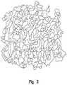
- FIG. 3depicts an illustrative 3D scan of a trabecular bone obtained from a humeral head in accordance with the techniques of the present invention.
- bonewas selected from a cadaver, sectioned, placed in a tube to scan, and then scanned at a resolution of 40 microns. While this scan was taken at a resolution of 40 microns, those of skill in the art will understand and appreciate that various other scanning resolutions can be utilized if desired. For instance in certain illustrative embodiments, a resolution of about 20 microns can be used.
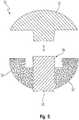
- FIG. 4shows cross-sectional view of a mesh wing that was created from a humeral head MicroCT scan in accordance with the teachings of the present invention
- FIG. 5shows a front, cross-sectional view of a stemless shoulder prosthesis 30 having a pair of illustrative mesh wings 38 (such as the mesh wing shown in FIG. 4 ) coupled thereto.
- a humeral head component 32is configured to be fitted inside a top portion of an internal chamber 34 of the body 36 of the prosthesis.
- the wings 38are connected to the body 36 and can be partially or fully porous, as well as have a partial solid section for increased strength if desired.
- a biological surface coatinge.g., a titanium porous plasma spray (PPS®) surface coating or a biomimetic coating (e.g., BoneMaster® coating), both of which are commercially available from Biomet
- PPS®titanium porous plasma spray
- a biomimetic coatinge.g., BoneMaster® coating
- the biological surface coatingcan have its associated biological performance further enhanced and modified if the coating is subjected to one or more of the following: grit blasting, hyaluronic acid (HA), an RGD-containing glycoprotein or bend coating.
Landscapes
- Health & Medical Sciences (AREA)
- Engineering & Computer Science (AREA)
- Animal Behavior & Ethology (AREA)
- Biomedical Technology (AREA)
- Veterinary Medicine (AREA)
- Public Health (AREA)
- General Health & Medical Sciences (AREA)
- Orthopedic Medicine & Surgery (AREA)
- Cardiology (AREA)
- Oral & Maxillofacial Surgery (AREA)
- Transplantation (AREA)
- Life Sciences & Earth Sciences (AREA)
- Heart & Thoracic Surgery (AREA)
- Vascular Medicine (AREA)
- Manufacturing & Machinery (AREA)
- Materials Engineering (AREA)
- Chemical & Material Sciences (AREA)
- Geometry (AREA)
- Physics & Mathematics (AREA)
- Prostheses (AREA)
Description
- The present invention generally relates to metallic structures having porous or mesh regions that represent the architecture of bone, and specifically to methods for imaging bone at pre-defined anatomic locations to create implants having porous regions that represent the bone's architecture at those imaged anatomic locations.
- Devices used to replace various joints of the human body are often implanted without the use of bone cement. To achieve and maintain long-term fixation and stability, these implants generally require some degree of bony on-growth or in-growth. The bony on-growth or in-growth necessary to promote and encourage the growth of surrounding bony and soft tissues, as well as to achieve desirable long-term fixation and stability properties, is often enhanced by fabricating porous coatings into one or more surfaces of the implant. Depending on the various features of the fabricated porous coatings (e.g., their pore size and roughness characteristics), the resulting osteoconductive properties of the implant can be improved in such a manner that the porous surfaces are able to function as scaffolds exhibiting desirable load-bearing strengths at the implantation site.
- While several orthopedic device companies commercially offer implants having porous surfaces, these products largely fail to adequately replicate the trabecular structure of bone. Additionally, when an implant is designed for a specific anatomic site, its interaction with the bone is limited to the areas immediately surrounding the implantation site. Bone architecture consists of trabeculae that are oriented in certain patterns in order to optimize the bone performance in that anatomic location. Since the magnitude and mode of differential loading to which a bone is subjected is influenced by the bone's anatomic location, by Wolff's law, trabecular struts in bone can also be expected to have anatomically site-specific architectures.
- Over the past few years, additive manufacturing and free-form fabrication processes have experienced some significant advances in terms of fabricating articles directly from computer controlled databases. For instance, rapid prototyping techniques allow many articles (e.g., prototype parts and mold dies) to be fabricated more quickly and cost effectively than conventional machining processes that require blocks of material to be specifically machined in accordance with engineering drawings.
- Illustrative modem rapid prototyping technologies include laser based additive manufacturing processes such as selective or direct metal laser sintering processes. These processes utilize digital electronic file formats (e.g., STL files) that can be printed into three-dimensional (3D) CAD models, and then utilized by a prototyping machine's software to construct various articles based on the geometric orientation of the 3D model. The constructed articles are produced additively in a layer-wise fashion by dispensing a laser-fusible powder one layer at a time. The powder is fused, re-melted or sintered, by the application of laser energy that is directed in raster-scan fashion to portions of the powder layer corresponding to a cross section of the article. After each layer of the powder is fused, an additional layer of powder is dispensed, and the process repeated, with fused portions or lateral layers fusing so as to fuse portions of previous laid layers until the article is complete.
- Additive manufacturing processes allow for highly complex geometries to be created directly (without tooling) from 3D CAD data, thereby permitting the creation of articles exhibiting high resolution surfaces. While these processes have been useful for detailing various surface properties of produced articles, such processes have struggled to replicate surfaces having reduced three-dimensional structural densities. For instance, such processes are unable to adequately replicate articles having randomized porous or partially randomized porous metallic structures, including metal porous structures having interconnected porosity. As such, there is a need for an additive manufacturing process that can replicate articles having reduced three-dimensional structural densities, including porous and partially porous metallic structures.
- Quadrani P et al1 describes the development of a high-resolution bone scaffold prototype using rapid prototyping, automatic image processing and computer-aided manufacturing.
1Quadrani P et al: "High-resolution 3D scaffold model for engineered tissue fabrication using a rapid prototyping technique, Medical and biological engineering and computing, Springer, Heildelberg, De, vol. 43, no. 2, 1 March 2005 (2005-03-01), pages 196-199, XP001507991, ISSN: 0140-0118, DOI: 10.1007BF02345954 - Sun W et al2 describes a methodology to generate bio-CAD models from high resolution non-invasive imaging, a medical imaging process and a 3D reconstruction technique.
2Sun W et al: "Bio-CAD modelling and its applications in computer-aided tissue engineering", Computer Aided Design, Elsevier Publishers BV., Barking, GB, vol. 37, no. 11, 15 September 2005 (2005-09-15), pages 1097-1114, XP027649874, ISSN: 0010-4485 US2007083266 describes methods, devices and instruments for resurfacing or replacing facet joints, uncovertebral joints and costovertebral joints.- Cooper D et al3 describes the impact of voxel size on micro-CT analysis of human cortical bone porosity.
3Cooper D et al: "Effect of Voxel Size on 3D Micro-CT Analysis of Cortical Bone Porosity", Calcified Tissue International, Springer-Verlag, NE, vol.80, no. 3, 5 March 2007 (2007-03-05), pages 211-219, XP019489021, ISSN: 1432-0827, DOI: 10.1007/S00223-005-0274-6 - Some embodiments of the present invention aim to improve upon and resolve some of the known deficiencies of the art.
- In accordance with one aspect of the present invention, a method of forming an implant having a porous region replicated from scanned bone is provided. The method comprises the steps of imaging bone with a high resolution digital scanner to generate a three-dimensional design model of the bone; removing a three-dimensional section from the design model; fabricating a porous region on a digital representation of the implant by replacing a solid portion of the digital implant with the section removed from the design model; and using an additive manufacturing technique to create a physical implant including the fabricated porous region.
- In further embodiments, the present invention is further directed to medical implants created in accordance with the present teachings. One such illustrative medical implant includes a metallic body having at least one porous surface replicated from a high resolution scan of bone and configured to promote bony on-growth or in-growth of tissue. The implant is generated, in accordance with certain illustrative embodiments, using an additive manufacturing technique, such as a Direct Metal Laser Sintering (DMLS) process, an Electron Beam Melting (EBM) process, Selective Laser Sintering (SLS), Fused Deposition Modeling (FDM), Stereolithography (SLA), Laminated Object Manufacturing, Powder Bed and Inkjet Head 3D Printing and Plaster-Based 3D Printing (PP).
- Other objects and benefits of the invention will become apparent from the following written description along with the accompanying figures.
- The above-mentioned aspects of the present invention and the manner of obtaining them will become more apparent and the invention itself will be better understood by reference to the following description of the embodiments of the invention taken in conjunction with the accompanying drawings, wherein:
FIG. 1 is a schematic flowchart of an illustrative process for creating a porous region of an implant from a trabecular bone in accordance with the teachings of the present invention;FIGS. 2a and2b are illustrative MicroCT scans of acetabular bone sections from cadaver pelvises imaged in accordance with the teachings of the present invention;FIG. 3 is an illustrative 3D scan of a trabecular bone obtained from a humeral head in accordance with the techniques of the present invention;FIG. 4 is a cross-sectional view of a mesh wing that was created from a humeral head MicroCT scan in accordance with the teachings of the present invention; andFIG. 5 is a front, cross-sectional view of a stemless shoulder prosthesis having a pair of mesh wings in accordance with the teachings of the present invention.- Corresponding reference characters indicate corresponding parts throughout the several views. Although the exemplification set out herein illustrates embodiments of the invention, in several forms, the embodiments disclosed below are not intended to be exhaustive or to be construed as limiting the scope of the invention to the precise forms disclosed.
- In the following detailed description, reference is made to the accompanying drawings, which form a part hereof. In the drawings, similar symbols typically identify similar components, unless context dictates otherwise. The illustrative embodiments described in the detailed description, drawings, and claims are not meant to be limiting. Other embodiments may be utilized, and other changes may be made, without departing from the spirit or scope of the subject matter presented herein. It will be readily understood that the disclosed aspects of the invention, as generally described herein, and illustrated in the Figures, may be arranged, substituted, combined, and designed in a wide variety of different configurations, all of which are explicitly contemplated and should be construed as being incorporated into this disclosure.
- Unless defined otherwise, all technical and scientific terms used herein have the same meaning as commonly understood by one of ordinary skill in the art to which this invention belongs. Although any method and materials similar or equivalent to those described herein can be used in the practice or testing of the present invention, the specific methods and materials are now described. Moreover, the techniques employed or contemplated herein are standard methodologies well known to one of ordinary skill in the art and the materials, methods and examples are illustrative only and not intended to be limiting.
- The present invention relates to methods of forming metallic structures having porous or mesh regions that represent the architecture of bone, and specifically methods for imaging bone at pre-defined anatomic locations to create implants having porous regions that represent the bone's architecture at those imaged anatomic locations. Generally, the methods of the present invention utilize laser technology by employing a variety of scanning strategies. It should be understood and appreciated herein that various different materials can be used to form the metallic structures of the present invention; however, in accordance with certain aspects of the present invention, the metal and metal alloys employed include, but are not limited to, stainless steel, cobalt chromium alloys, titanium and its alloys, tantalum and niobium. It should also be understood and appreciated herein that the present invention can be used for various different medical device applications, including applications in which bone and soft tissue interlock with a component or where a controlled structure is required to more closely match the mechanical properties of the device with surrounding tissue.
- In accordance with certain aspects of the present invention, an additive manufacturing process is utilized to create a porous metal structure for an orthopedic device. According to one illustrative embodiment, the porous metal structure is configured to mimic the trabecular architecture of bone at the specific anatomic site where the device is to be implanted. It should be understood and appreciated herein that the teachings of the present invention can be utilized with various different anatomic applications, including, but not limited to, hip procedures, knee procedures, spinal procedures, shoulder procedures, hand, finger, wrist and elbow procedures and foot, toe and ankle procedures.
- Moving now to
FIG. 1 , anillustrative process 10 for creating a porous region of an implant from a trabecular bone is now discussed. In accordance with this illustrative embodiment, a bone sample is first obtained from a region of interest (e.g., humeral head) from a pre-defined and site-specific anatomic site of a specimen (e.g., a cadaver specimen) (step 12). Once the bone sample is obtained from the specimen, the sample is scanned using a high resolution imaging technique (step 14). As those of skill in the art will understand and appreciate, various methods can be employed to quantitatively assess the microstructure of trabecular bone in accordance with the teachings of the present invention. Some of these imaging techniques include, but are not limited to, high-resolution CT (hrCT) and microCT (µCT) techniques and high-resolution magnetic resonance (hrMR) and microMR (µMR) techniques. - In accordance with specific aspects of the present invention, the obtained bone sample is scanned using a high resolution microCT scanner. For instance,
FIGS. 2a and2b depict acetabular scans obtained from cadaver pelvises using high-resolution microCT scanners. Depending on the selected anatomic site that is used to obtain the bone sample, it is possible that various non-uniformities or discontinuities may exist in the bone structure of the scanned sample. When such artifacts are present in the scanned bone sample image, it may be desirable to clean up or remove these artifacts from the image, thereby leaving only the desired trabecular structure (step 16). For example, as the scanned image ofFIG. 2a reveals, the bone in the medial region at the apex has a discontinuity (shown by reference numeral 202), while the remaining regions generally contain a trabecular architecture that is uniform and continuous. While various different known image processing techniques can be used to remove the undesired artifacts from the image (step 16), in accordance with certain aspects of the present invention, bone from regions exhibiting desired trabecular structure can be selected and superimposed to fill in the region or regions containing defects. Alternatively, and in accordance with other embodiments of the present invention, a region of the original bone sample scan containing optimal trabecular architecture can be identified and then used as a unit cell for the entire porous region of the structure to be created. - Once the undesirable artifacts are removed, the scan having the optimal or desired physical properties of the trabecular structure is chosen and the scan converted to a digital file format that is appropriate for printing the porous metal structure using an additive manufacturing process (e.g., STL format, AMF format, etc.) (step 18). In accordance with certain illustrative embodiments of the present teachings, an STL file (i.e., the file format native to the stereolithography CAD software created by 3D Systems) representing the trabecular structure is produced from the microCT scan. In accordance with this specific embodiment, the file can be sliced and the data sent digitally to a scanning control to permit the generation of a layer-by-layer facsimile replica (i.e., a 3D design model) of the scanned sample (step 20).
- Once the 3D model is generated, one or more 3D sections of the trabecular structure can be removed or cut from the model to form the desired porous or mesh regions to be fabricated into the implant (step 22). In accordance with certain aspects of the present invention, bone can be selected based on intersection with the model. Moreover, information can be taken from the porous region where the implant would sit in the bone. It should be understood and appreciated herein that the porous or mesh regions of the final metal structures created in accordance with the various embodiments of the present teachings contain the trabecular architecture of natural bone, and as such, the porous structure unit cells do not require the use of a mathematical model to be created. Accordingly, the porous structure of the metallic device created herein will mimic the trabecular architecture of the natural bone from the specific targeted anatomic site.
- After the desired mesh regions of the metallic structure are formed, bone sections are then added to the solid portions of the implant model using a software program, such as computer aided design "CAD" software program or the like (step 24). It should be understood and appreciated herein that care should be taken to align the bone sections as they were originally aligned in the native bone when applying the techniques of the present invention as disclosed herein. More particularly, different regions of a bone, such as the humerus, have different trabecular properties (e.g., thickness, length, etc.) and orientation that should be closely replicated in the implant mesh design.
- After the implant is modeled, an additive manufacturing process is then employed to manufacture the implant from the 3D model data (step 26). Additive manufacturing processes are generally known in the art and typically involve making objects from 3D model data by joining materials together in a layer-by-layer fashion. Some additive manufacturing processes that can be utilized in accordance with the teachings of the present invention include, but are not limited to, Direct Metal Laser Sintering (DMLS) process, an Electron Beam Melting (EBM) process, Selective Laser Sintering (SLS), Fused Deposition Modeling (FDM), Stereolithography (SLA), Laminated Object Manufacturing, Powder Bed and Inkjet Head 3D Printing, Plaster-Based 3D Printing (PP) and the like.
- While not required herein, it should be understood and appreciated that traditional manufacturing techniques (e.g., casting, molding, forming, machining, joining/welding, polishing, blasting, etc.) can also be used in conjunction with the additive manufacturing processes of the present invention if desired. For instance, in accordance with certain aspects of the present invention, it may be desirable to add tapers, grooves and/or threads to the fabricated article. If such additional features are desired, those of skill in the art can incorporate additional manufacturing techniques into the various embodiments of the present teachings without straying from the spirit or scope of the present invention.
- In accordance with further aspects of the present teachings, the inventive techniques described herein can be used to form an implant from scanned bone to fill a bone void. In accordance with this illustrative embodiment, a voided bone region is imaged with a high digital scanner (e.g., a microCT scanner) to generate a three dimensional design model of the voided bone region. Once the three dimensional design model of the voided bone region is provided, a digital representation of a non-voided bone region (i.e., a section or sample of bone that does not contain a non-uniformity or void) is provided. As those of skill in the art will understand and appreciate herein, the three dimensional representation of the non-voided bone region can be generated from various different sources, including either an autologous or a non-autologous source. For instance, in accordance with certain aspects of the present invention, the non-voided bone region can be obtained by scanning a good section of the patient's bone - i.e., a section that is devoid of any non-uniformities or discontinuities. Alternatively, in accordance with further illustrative aspects of the present invention, the non-voided bone region can be taken from a computerized database of stock non-voided bone images. As such, it should be understood that the present invention is not intended to be limited herein.
- Once the digital representation of the non-voided bone region is provided, a three dimensional section of the non-voided bone region is removed from the image. In accordance with this aspect of the present invention, the removed three dimensional section should have a size that substantially matches the size of the voided bone region. The removed three dimensional section of the scanned non-voided bone is then converted to a file format that is appropriate for printing with an additive manufacturing process (e.g., STL format, AMF format, etc.) (step 18). In accordance with certain illustrative embodiments of the present teachings, an STL file (i.e., the file format native to the stereolithography CAD software created by 3D Systems) representing the removed non-voided bone region is produced from the microCT scan.
- The removed three dimensional section of the non-voided bone region is then subjected to an additive manufacturing process so that a physical implant is manufactured from the 3D design model. As explained in detail above, additive manufacturing processes are generally known in the art and typically involve making objects from 3D model data by joining materials together in a layer-by-layer fashion. Some additive manufacturing processes that can be utilized in accordance with the teachings of the present invention include, but are not limited to, Direct Metal Laser Sintering (DMLS) process, an Electron Beam Melting (EBM) process, Selective Laser Sintering (SLS), Fused Deposition Modeling (FDM), Stereolithography (SLA), Laminated Object Manufacturing, Powder Bed and Inkjet Head 3D Printing, Plaster-Based 3D Printing (PP) and the like.
- In accordance with this aspect of the present invention, the manufactured physical implant of the non-voided bone region can then be installed within the voided bone region.
- Advantages and improvements of the processes, methods and devices of the present invention are demonstrated in the following example. This example is illustrative only and is not intended to limit or preclude other embodiments of the present invention.
- Example 1:
FIG. 3 depicts an illustrative 3D scan of a trabecular bone obtained from a humeral head in accordance with the techniques of the present invention. In accordance with this illustrative embodiment, bone was selected from a cadaver, sectioned, placed in a tube to scan, and then scanned at a resolution of 40 microns. While this scan was taken at a resolution of 40 microns, those of skill in the art will understand and appreciate that various other scanning resolutions can be utilized if desired. For instance in certain illustrative embodiments, a resolution of about 20 microns can be used. FIG. 4 shows cross-sectional view of a mesh wing that was created from a humeral head MicroCT scan in accordance with the teachings of the present invention, whileFIG. 5 shows a front, cross-sectional view of astemless shoulder prosthesis 30 having a pair of illustrative mesh wings 38 (such as the mesh wing shown inFIG. 4 ) coupled thereto. More specifically, and with particular reference toFIG. 5 , ahumeral head component 32 is configured to be fitted inside a top portion of aninternal chamber 34 of thebody 36 of the prosthesis. Thewings 38 are connected to thebody 36 and can be partially or fully porous, as well as have a partial solid section for increased strength if desired. It should be understood and appreciated herein that fully porous wings would allow bone to grow completely through the wings, thereby enhancing the stability of the device. It should also be understood and appreciated herein that in accordance with certain aspects of the present invention, it may be desirable to utilize a biological surface coating (e.g., a titanium porous plasma spray (PPS®) surface coating or a biomimetic coating (e.g., BoneMaster® coating), both of which are commercially available from Biomet), with the porous or nonporous surfaces to create a barrier to particulate debris (metallic, polyethylene or PMMA) and/or to further promote and increase the fixation or osseintegration of the bony in-growth through the wings. In accordance with certain aspects of the present invention, the biological surface coating can have its associated biological performance further enhanced and modified if the coating is subjected to one or more of the following: grit blasting, hyaluronic acid (HA), an RGD-containing glycoprotein or bend coating.- While this illustrative example shows the present teachings utilized with stemless shoulder prosthesis, it should be understood and appreciated herein that the present invention can be incorporated into any implant design that utilizes a porous or mesh structure for bony on-growth or in-growth.
- While an exemplary embodiment incorporating the principles of the present invention has been disclosed hereinabove, the present invention is not limited to the disclosed embodiments. Instead, this application is intended to cover any variations, uses, or adaptations of the invention using its general principles. Further, this application is intended to cover such departures from the present disclosure as come within known or customary practice in the art to which this invention pertains and which fall within the limits of the appended claims.
Claims (15)
- A method (10) of forming an implant (30) having a porous region (38) replicated from scanned bone, the method comprising the steps of::imaging (14) bone with a high resolution digital scanner to generate (20) a three-dimensional design model of the bone;removing (22) a three-dimensional section from the design model;fabricating (24) a porous region on a digital representation of the implant by replacing a solid portion of the digital implant with the section removed from the design model; andusing an additive manufacturing technique to create (26) a physical implant (30) including the fabricated porous region.
- The method of claim 1, wherein the step of imaging the bone with a high resolution digital scanner comprises scanning the bone with a computed tomography (CT) scanner.
- The method of claim 2, wherein the step of scanning the bone with a computed tomography (CT) scanner comprises scanning the bone with a MicroCT scanner.
- The method of claim 1, further comprising modifying any artifacts from the three-Dimensional design model of the bone.
- The method of claim 4, wherein the step of modifying any artifacts from the three-dimensional design model comprises removing (16) defective regions (202) of the design model containing non-uniformities or discontinuities by filling the defective regions with a selected and superimposed region of the bone model that does not contain a non-uniformity or a discontinuity.
- The method of claim 1, further comprising converting (18) the imaged bone to a digital file format.
- The method of claim 1, wherein the step of fabricating a porous region on a digital representation of the implant comprises utilizing a computer aided design (CAD) program to fabricate a porous region that structurally replicates the architecture of the bone, the porous region being selected from one of a hip, shoulder, knee, spine, elbow, wrist, ankle, finger and toe.
- The method of claim 1, wherein the step of using an additive manufacturing technique to create a physical implant comprises using a Direct Metal Laser Sintering (DMLS) process or an Electron Beam Melting (EBM) process, Selective Laser Sintering (SLS), Fused Deposition Modeling (FDM), Stereolithography (SLA), Laminated Object Manufacturing, Powder Bed and Inkjet Head 3D Printing and Plaster-Based 3D Printing (PP).
- The method of claim 1, further comprising performing an additional manufacturing process on the physical implant to modify one or more features, the manufacturing process being selected from at least one of casting, molding, forming, machining, joining, polishing, blasting and welding.
- The method of claim 1, wherein the step of imaging bone with a high resolution digital scanner to generate a three-dimensional design model of the bone comprises:creating (14) a digital image of the bone with a microCT scanner;removing (16) any defective artifacts from the digital image; andconverting (18, 20) the digital image to a three-dimensional design model of the bone;
- The method of claim 10, wherein the step of removing any defective artifacts comprises removing any defective regions (202) containing a non-uniformity or discontinuity from the image by filling the defective regions with a selected and superimposed region of the digital image that does not contain a non-uniformity or a discontinuity.
- A medical implant (30), comprising:a metallic body having at least one porous surface (38) replicated from a high resolution scan of bone and configured to promote bony on-growth or in-growth of tissue;wherein the implant is generated using an additive manufacturing technique.
- The medical implant of claim 12, further comprising a biological surface coating configured to create a barrier to particulate debris.
- The medical implant of claim 13, wherein the biological surface coating is a titanium porous plasma spray surface coating or a biomimetic coating.
- The medical implant of claim 14, wherein the biological surface coating is capable of exhibiting an enhanced biological performance when subjected to at least one of grit blasting, hyaluronic acid (HA), an RGD-containing glycoprotein or bend coating.
Applications Claiming Priority (2)
| Application Number | Priority Date | Filing Date | Title |
|---|---|---|---|
| US13/554,484US8843229B2 (en) | 2012-07-20 | 2012-07-20 | Metallic structures having porous regions from imaged bone at pre-defined anatomic locations |
| PCT/US2013/046711WO2014014610A1 (en) | 2012-07-20 | 2013-06-20 | Metallic structures having porous regions from imaged bone at pre-defined anatomical locations |
Publications (2)
| Publication Number | Publication Date |
|---|---|
| EP2874570A1 EP2874570A1 (en) | 2015-05-27 |
| EP2874570B1true EP2874570B1 (en) | 2017-01-11 |
Family
ID=48782613
Family Applications (1)
| Application Number | Title | Priority Date | Filing Date |
|---|---|---|---|
| EP13735500.4AActiveEP2874570B1 (en) | 2012-07-20 | 2013-06-20 | Metallic structures having porous regions from imaged bone at pre-defined anatomical locations |
Country Status (3)
| Country | Link |
|---|---|
| US (3) | US8843229B2 (en) |
| EP (1) | EP2874570B1 (en) |
| WO (1) | WO2014014610A1 (en) |
Cited By (8)
| Publication number | Priority date | Publication date | Assignee | Title |
|---|---|---|---|---|
| US9993341B2 (en) | 2012-07-20 | 2018-06-12 | Biomet Manufacturing, Llc | Metallic structures having porous regions from imaged bone at pre-defined anatomic locations |
| US10405993B2 (en) | 2013-11-13 | 2019-09-10 | Tornier Sas | Shoulder patient specific instrument |
| US10456143B2 (en) | 2017-03-02 | 2019-10-29 | Titanium Fusion Technologies, Llc | Composite joint arthroplasty systems and methods |
| US10716676B2 (en) | 2008-06-20 | 2020-07-21 | Tornier Sas | Method for modeling a glenoid surface of a scapula, apparatus for implanting a glenoid component of a shoulder prosthesis, and method for producing such a component |
| US10959742B2 (en) | 2017-07-11 | 2021-03-30 | Tornier, Inc. | Patient specific humeral cutting guides |
| US11065016B2 (en) | 2015-12-16 | 2021-07-20 | Howmedica Osteonics Corp. | Patient specific instruments and methods for joint prosthesis |
| US11166733B2 (en) | 2017-07-11 | 2021-11-09 | Howmedica Osteonics Corp. | Guides and instruments for improving accuracy of glenoid implant placement |
| US12193939B2 (en) | 2017-12-29 | 2025-01-14 | Howmedica Osteonics Corp. | Patient specific humeral implant components |
Families Citing this family (164)
| Publication number | Priority date | Publication date | Assignee | Title |
|---|---|---|---|---|
| US20060147332A1 (en) | 2004-12-30 | 2006-07-06 | Howmedica Osteonics Corp. | Laser-produced porous structure |
| AU2003261497B2 (en) | 2002-11-08 | 2009-02-26 | Howmedica Osteonics Corp. | Laser-produced porous surface |
| AU2004212942A1 (en) | 2003-02-14 | 2004-09-02 | Depuy Spine, Inc. | In-situ formed intervertebral fusion device |
| US20040267367A1 (en) | 2003-06-30 | 2004-12-30 | Depuy Acromed, Inc | Intervertebral implant with conformable endplate |
| US8636802B2 (en) | 2004-03-06 | 2014-01-28 | DePuy Synthes Products, LLC | Dynamized interspinal implant |
| US8303665B2 (en) | 2004-06-15 | 2012-11-06 | Tornier Sas | Glenoidal component, set of such components and shoulder prosthesis incorporating such a glenoidal component |
| US8728387B2 (en) | 2005-12-06 | 2014-05-20 | Howmedica Osteonics Corp. | Laser-produced porous surface |
| WO2008070863A2 (en) | 2006-12-07 | 2008-06-12 | Interventional Spine, Inc. | Intervertebral implant |
| US8900307B2 (en) | 2007-06-26 | 2014-12-02 | DePuy Synthes Products, LLC | Highly lordosed fusion cage |
| EP2237748B1 (en) | 2008-01-17 | 2012-09-05 | Synthes GmbH | An expandable intervertebral implant |
| US8549888B2 (en) | 2008-04-04 | 2013-10-08 | Nuvasive, Inc. | System and device for designing and forming a surgical implant |
| US8936641B2 (en) | 2008-04-05 | 2015-01-20 | DePuy Synthes Products, LLC | Expandable intervertebral implant |
| US9220547B2 (en) | 2009-03-27 | 2015-12-29 | Spinal Elements, Inc. | Flanged interbody fusion device |
| US9526620B2 (en) | 2009-03-30 | 2016-12-27 | DePuy Synthes Products, Inc. | Zero profile spinal fusion cage |
| US9901455B2 (en)* | 2009-11-25 | 2018-02-27 | Nathan C. Moskowitz | Total artificial spino-laminar prosthetic replacement |
| US9393129B2 (en) | 2009-12-10 | 2016-07-19 | DePuy Synthes Products, Inc. | Bellows-like expandable interbody fusion cage |
| FR2955247B1 (en) | 2010-01-21 | 2013-04-26 | Tornier Sa | GLENOIDAL COMPONENT OF SHOULDER PROSTHESIS |
| US8979860B2 (en) | 2010-06-24 | 2015-03-17 | DePuy Synthes Products. LLC | Enhanced cage insertion device |
| US9907560B2 (en) | 2010-06-24 | 2018-03-06 | DePuy Synthes Products, Inc. | Flexible vertebral body shavers |
| US8623091B2 (en) | 2010-06-29 | 2014-01-07 | DePuy Synthes Products, LLC | Distractible intervertebral implant |
| US9402732B2 (en) | 2010-10-11 | 2016-08-02 | DePuy Synthes Products, Inc. | Expandable interspinous process spacer implant |
| FR2966343B1 (en) | 2010-10-22 | 2012-12-07 | Tornier Sa | SET OF GLENOIDIAN COMPONENTS OF SHOULDER PROSTHESIS |
| FR2971144A1 (en) | 2011-02-08 | 2012-08-10 | Tornier Sa | GLENOIDAL IMPLANT FOR SHOULDER PROSTHESIS AND SURGICAL KIT |
| US8771354B2 (en) | 2011-10-26 | 2014-07-08 | George J. Picha | Hard-tissue implant |
| US11207132B2 (en) | 2012-03-12 | 2021-12-28 | Nuvasive, Inc. | Systems and methods for performing spinal surgery |
| US9180010B2 (en) | 2012-04-06 | 2015-11-10 | Howmedica Osteonics Corp. | Surface modified unit cell lattice structures for optimized secure freeform fabrication |
| US9907654B2 (en)* | 2012-12-11 | 2018-03-06 | Dr. H.C. Robert Mathys Stiftung | Bone substitute and method for producing the same |
| US9717601B2 (en) | 2013-02-28 | 2017-08-01 | DePuy Synthes Products, Inc. | Expandable intervertebral implant, system, kit and method |
| US9522070B2 (en) | 2013-03-07 | 2016-12-20 | Interventional Spine, Inc. | Intervertebral implant |
| US20140361453A1 (en)* | 2013-06-10 | 2014-12-11 | Vaios Triantafyllou | Method and apparatus for appreciating artwork |
| GB201310762D0 (en)* | 2013-06-17 | 2013-07-31 | Rolls Royce Plc | An additive layer manufacturing method |
| US10016811B2 (en)* | 2013-08-09 | 2018-07-10 | David J. Neal | Orthopedic implants and methods of manufacturing orthopedic implants |
| US9848922B2 (en) | 2013-10-09 | 2017-12-26 | Nuvasive, Inc. | Systems and methods for performing spine surgery |
| EP3057524B1 (en) | 2013-10-10 | 2019-11-20 | Imascap | Method for designing and producing a shoulder surgery guide |
| EP3925574A1 (en) | 2013-11-08 | 2021-12-22 | Imascap | Pre-operatively planned adaptive glenoid implants and method for planning its design |
| WO2015103090A1 (en) | 2014-01-03 | 2015-07-09 | Tornier, Inc. | Reverse shoulder systems |
| CN106456331A (en)* | 2014-03-04 | 2017-02-22 | 皇家墨尔本理工大学 | Method for producing custom orthopedic implants |
| US10111753B2 (en) | 2014-05-23 | 2018-10-30 | Titan Spine, Inc. | Additive and subtractive manufacturing process for producing implants with homogeneous body substantially free of pores and inclusions |
| CA2949457A1 (en)* | 2014-05-27 | 2015-12-03 | Osiris Biomed 3D, Llc | Database and marketplace for medical devices |
| US10709509B2 (en) | 2014-06-17 | 2020-07-14 | Nuvasive, Inc. | Systems and methods for planning, performing, and assessing spinal correction during surgery |
| US10687956B2 (en) | 2014-06-17 | 2020-06-23 | Titan Spine, Inc. | Corpectomy implants with roughened bioactive lateral surfaces |
| US10314942B2 (en) | 2014-06-30 | 2019-06-11 | Bacterin International, Inc. | Manufacture of biomaterial implants via three-dimensional printing technology |
| AU2015297051A1 (en)* | 2014-07-31 | 2017-03-02 | Ossis Limited | Improved implant surface |
| TWI514316B (en)* | 2014-10-09 | 2015-12-21 | Xyzprinting Inc | Method for arranging joints to 3D model, arranging apparatus for the method, and application program for using the same |
| WO2016061148A1 (en)* | 2014-10-16 | 2016-04-21 | Additive Innovations, Llc | Additive manufactured titanium bone device |
| US10433893B1 (en) | 2014-10-17 | 2019-10-08 | Nuvasive, Inc. | Systems and methods for performing spine surgery |
| US9857784B2 (en)* | 2014-11-12 | 2018-01-02 | International Business Machines Corporation | Method for repairing with 3D printing |
| CN104382670B (en)* | 2014-12-08 | 2016-05-04 | 西安交通大学 | A kind of bionical construction method of artificial organs |
| US10279078B2 (en) | 2014-12-31 | 2019-05-07 | Bacterin International, Inc. | Crosslinkable 3D printed biomaterial-based implants and methods of manufacture thereof |
| DE102015100088A1 (en)* | 2015-01-07 | 2016-07-07 | Airbus Operations Gmbh | Production of metallic components with integrated crack stopper |
| US10028841B2 (en) | 2015-01-27 | 2018-07-24 | K2M, Inc. | Interbody spacer |
| US20160213405A1 (en) | 2015-01-27 | 2016-07-28 | K2M, Inc. | Vertebral plate systems and methods of use |
| US10098746B1 (en) | 2015-02-13 | 2018-10-16 | Nextstep Arthropedix, LLC | Medical implants having desired surface features and methods of manufacturing |
| US11426290B2 (en) | 2015-03-06 | 2022-08-30 | DePuy Synthes Products, Inc. | Expandable intervertebral implant, system, kit and method |
| US10722374B2 (en) | 2015-05-05 | 2020-07-28 | Tornier, Inc. | Convertible glenoid implant |
| US10098749B2 (en)* | 2015-07-31 | 2018-10-16 | Ryan A. Jefferis | Proximal interphalangeal joint prothesis |
| US9824491B2 (en) | 2015-09-09 | 2017-11-21 | Siemens Healthcare Gmbh | Data driven framework for optimizing artificial organ printing and scaffold selection for regenerative medicine |
| US11376660B2 (en) | 2015-11-20 | 2022-07-05 | Titan Spine, Inc. | Processes for additively manufacturing orthopedic implants |
| TWI726940B (en) | 2015-11-20 | 2021-05-11 | 美商泰坦脊柱股份有限公司 | Processes for additively manufacturing orthopedic implants |
| AU2016369593B2 (en) | 2015-12-16 | 2021-04-01 | Nuvasive, Inc. | Porous spinal fusion implant |
| CN105434085A (en)* | 2016-01-11 | 2016-03-30 | 王金成 | 3D printed individualized customized full wrist joint and manufacturing method thereof |
| CN105455925A (en)* | 2016-01-11 | 2016-04-06 | 佛山市安齿生物科技有限公司 | Method for preparing bone repair implant on basis of selective laser melting technology |
| WO2017186255A1 (en)* | 2016-04-26 | 2017-11-02 | Hafez Mahmoud Alm El Din | An apparatus and system for acquiring data from bones and joints, plan surgery and manufacture instruments or implants |
| WO2017201371A1 (en)* | 2016-05-19 | 2017-11-23 | University Of Pittsburgh-Of The Commonwealth System Of Higher Education | Biomimetic plywood motifs for bone tissue engineering |
| US11638645B2 (en) | 2016-05-19 | 2023-05-02 | University of Pittsburgh—of the Commonwealth System of Higher Education | Biomimetic plywood motifs for bone tissue engineering |
| US11510788B2 (en) | 2016-06-28 | 2022-11-29 | Eit Emerging Implant Technologies Gmbh | Expandable, angularly adjustable intervertebral cages |
| EP3474784A2 (en) | 2016-06-28 | 2019-05-01 | Eit Emerging Implant Technologies GmbH | Expandable and angularly adjustable intervertebral cages with articulating joint |
| CA3032664A1 (en) | 2016-08-03 | 2018-02-08 | Titan Spine, Inc. | Implant surfaces that enhance osteoinduction |
| US11804305B2 (en) | 2016-10-26 | 2023-10-31 | Mosaic Ventures, Llc | Contralateral image orthopedic implant |
| US10888433B2 (en) | 2016-12-14 | 2021-01-12 | DePuy Synthes Products, Inc. | Intervertebral implant inserter and related methods |
| AU2018225123C1 (en) | 2017-02-21 | 2020-03-19 | Biomet Manufacturing, Llc | Implants for bridging osseous defects |
| US12083027B2 (en) | 2017-03-02 | 2024-09-10 | Optimotion Implants LLC | Universal femoral trial system and methods |
| US11406502B2 (en) | 2017-03-02 | 2022-08-09 | Optimotion Implants LLC | Orthopedic implants and methods |
| US11324606B2 (en) | 2017-03-10 | 2022-05-10 | Gary A. Zwick | Spinal interbody cage comprising a bulk interbody cage, a top face, a bottom face, pillars, and slots |
| EP3592283B1 (en) | 2017-03-10 | 2024-05-08 | Alps Holding Llc | Hard-tissue implant comprising a bulk implant, a face, pillars, slots, and at least one support member |
| WO2018165403A1 (en)* | 2017-03-10 | 2018-09-13 | Applied Medical Research, Inc. | Hard-tissue stem implant comprising a bulk stem implant, a face, pillars for contacting a cancellous portion of a hard tissue, and slots, wherein the pillars are prearranged to match an underlying structure of the cancellous portion |
| US10398563B2 (en) | 2017-05-08 | 2019-09-03 | Medos International Sarl | Expandable cage |
| US11298747B2 (en) | 2017-05-18 | 2022-04-12 | Howmedica Osteonics Corp. | High fatigue strength porous structure |
| EP3415108B1 (en) | 2017-05-25 | 2024-09-04 | Stryker European Operations Holdings LLC | Fusion cage with integrated fixation and insertion features |
| US11344424B2 (en) | 2017-06-14 | 2022-05-31 | Medos International Sarl | Expandable intervertebral implant and related methods |
| US10940016B2 (en) | 2017-07-05 | 2021-03-09 | Medos International Sarl | Expandable intervertebral fusion cage |
| US11006981B2 (en) | 2017-07-07 | 2021-05-18 | K2M, Inc. | Surgical implant and methods of additive manufacturing |
| US11166764B2 (en) | 2017-07-27 | 2021-11-09 | Carlsmed, Inc. | Systems and methods for assisting and augmenting surgical procedures |
| WO2019051260A1 (en) | 2017-09-08 | 2019-03-14 | Pioneer Surgical Technology, Inc. | Intervertebral implants, instruments, and methods |
| US11166822B2 (en) | 2017-09-08 | 2021-11-09 | Orthopedix, Inc. | Implant for total wrist replacement |
| WO2019079104A2 (en) | 2017-10-16 | 2019-04-25 | Imascap Sas | Shoulder implants and methods of use and assembly |
| BR112020007853A2 (en)* | 2017-10-20 | 2020-10-13 | Centinel Spine, Llc | porous implantable interbody devices |
| US11112770B2 (en) | 2017-11-09 | 2021-09-07 | Carlsmed, Inc. | Systems and methods for assisting a surgeon and producing patient-specific medical devices |
| CN107822746A (en)* | 2017-11-16 | 2018-03-23 | 北京中安泰华科技有限公司 | Personalized class trabecular bone structure knee-joint prosthesis and preparation method |
| US11083586B2 (en) | 2017-12-04 | 2021-08-10 | Carlsmed, Inc. | Systems and methods for multi-planar orthopedic alignment |
| FR3074417B1 (en)* | 2017-12-05 | 2022-04-08 | Gemon Jean Pierre | PROCESS FOR MANUFACTURING A CUSTOM-MADE IMPLANT |
| US10183442B1 (en) | 2018-03-02 | 2019-01-22 | Additive Device, Inc. | Medical devices and methods for producing the same |
| USD870889S1 (en) | 2018-03-02 | 2019-12-24 | Restor3D, Inc. | Cutout airway stent |
| USD870890S1 (en) | 2018-03-02 | 2019-12-24 | Restor3D, Inc. | Spiral airway stent |
| USD870888S1 (en) | 2018-03-02 | 2019-12-24 | Restor3D, Inc. | Accordion airway stent |
| USD871577S1 (en) | 2018-03-02 | 2019-12-31 | Restor3D, Inc. | Studded airway stent |
| US11432943B2 (en) | 2018-03-14 | 2022-09-06 | Carlsmed, Inc. | Systems and methods for orthopedic implant fixation |
| US11278427B2 (en) | 2018-04-10 | 2022-03-22 | Gary A. Zick, Trustee Of The Everest Trust Uta April 20, 2017 | Spinal interbody cage comprising top and bottom faces with mesh structures, pillars and slots |
| US11439514B2 (en) | 2018-04-16 | 2022-09-13 | Carlsmed, Inc. | Systems and methods for orthopedic implant fixation |
| US11376054B2 (en) | 2018-04-17 | 2022-07-05 | Stryker European Operations Limited | On-demand implant customization in a surgical setting |
| US10744003B2 (en) | 2018-05-08 | 2020-08-18 | Globus Medical, Inc. | Intervertebral spinal implant |
| US10682238B2 (en) | 2018-05-08 | 2020-06-16 | Globus Medical, Inc. | Intervertebral spinal implant |
| US10531962B2 (en) | 2018-05-08 | 2020-01-14 | Globus Medical, Inc. | Intervertebral spinal implant |
| US10925746B2 (en) | 2018-07-25 | 2021-02-23 | Orthopedix, Inc. | Patient specific carpal implant |
| US10918487B2 (en) | 2018-07-25 | 2021-02-16 | Orthopedix, Inc. | Prosthetic implant caps |
| USD958151S1 (en) | 2018-07-30 | 2022-07-19 | Carlsmed, Inc. | Display screen with a graphical user interface for surgical planning |
| WO2020056186A1 (en) | 2018-09-12 | 2020-03-19 | Carlsmed, Inc. | Systems and methods for orthopedic implants |
| AU2019342137A1 (en) | 2018-09-20 | 2021-03-25 | Spinal Elements, Inc. | Spinal implant device |
| US11446156B2 (en) | 2018-10-25 | 2022-09-20 | Medos International Sarl | Expandable intervertebral implant, inserter instrument, and related methods |
| EP3888095A4 (en) | 2018-11-29 | 2022-08-31 | Carlsmed, Inc. | SYSTEMS AND PROCEDURES FOR ORTHOPEDIC IMPLANTS |
| CN109481092B (en)* | 2018-12-04 | 2024-06-04 | 北京市春立正达医疗器械股份有限公司 | Bone trabecular structure and prosthesis using the same |
| US11039931B2 (en) | 2019-02-01 | 2021-06-22 | Globus Medical, Inc. | Intervertebral spinal implant |
| US11213403B2 (en) | 2019-03-14 | 2022-01-04 | Medos International Sarl | Devices and methods for optimized spinal fixation |
| US10889053B1 (en) | 2019-03-25 | 2021-01-12 | Restor3D, Inc. | Custom surgical devices and method for manufacturing the same |
| WO2020231656A2 (en)* | 2019-05-13 | 2020-11-19 | Tornier, Inc. | Patient-matched orthopedic implant |
| JP7257546B2 (en) | 2019-05-13 | 2023-04-13 | ハウメディカ オステオニクス コーポレイション | Glenoid baseplate and implant assembly |
| CN110223391A (en)* | 2019-06-24 | 2019-09-10 | 秒针信息技术有限公司 | The 3D printing method and device of the three-dimensional stereo model of bone |
| EP3771509A1 (en) | 2019-08-01 | 2021-02-03 | Howmedica Osteonics Corp. | Multi-stage additive manufacturing process with inserts |
| EP3982848A1 (en) | 2019-08-09 | 2022-04-20 | Howmedica Osteonics Corp. | Apparatuses and methods for implanting glenoid prostheses |
| CN112402065A (en)* | 2019-08-23 | 2021-02-26 | 北京智塑健康科技有限公司 | Manufacturing method, system and device of fusion device and storage medium thereof |
| JP7335428B2 (en) | 2019-09-11 | 2023-08-29 | アルプス ホールディング エルエルシー | An implant comprising a first set and a second set of pillars for attaching a tendon or ligament to hard tissue |
| US11534307B2 (en) | 2019-09-16 | 2022-12-27 | K2M, Inc. | 3D printed cervical standalone implant |
| US11751997B2 (en)* | 2019-10-15 | 2023-09-12 | b-ONE Medical (Suzhou) Co., Ltd. | Implant and a method of making the implant and a method of calculating porosity of a porous material |
| US10902944B1 (en) | 2020-01-06 | 2021-01-26 | Carlsmed, Inc. | Patient-specific medical procedures and devices, and associated systems and methods |
| US11376076B2 (en) | 2020-01-06 | 2022-07-05 | Carlsmed, Inc. | Patient-specific medical systems, devices, and methods |
| USD920517S1 (en) | 2020-01-08 | 2021-05-25 | Restor3D, Inc. | Osteotomy wedge |
| USD920515S1 (en) | 2020-01-08 | 2021-05-25 | Restor3D, Inc. | Spinal implant |
| US10772732B1 (en) | 2020-01-08 | 2020-09-15 | Restor3D, Inc. | Sheet based triply periodic minimal surface implants for promoting osseointegration and methods for producing same |
| USD920516S1 (en) | 2020-01-08 | 2021-05-25 | Restor3D, Inc. | Osteotomy wedge |
| US11426286B2 (en) | 2020-03-06 | 2022-08-30 | Eit Emerging Implant Technologies Gmbh | Expandable intervertebral implant |
| WO2021202101A1 (en) | 2020-04-01 | 2021-10-07 | Arthrex, Inc. | Systems and methods of forming orthopaedic implants including printed augments |
| US11752555B1 (en) | 2020-04-08 | 2023-09-12 | Eagle Technology, Llc | Method for making a radiation shield using fused filament deposition |
| AU2021202801A1 (en) | 2020-05-07 | 2021-11-25 | Howmedica Osteonics Corp. | Stemless metaphyseal humeral implant |
| US12226315B2 (en) | 2020-08-06 | 2025-02-18 | Carlsmed, Inc. | Kinematic data-based patient-specific artificial discs, implants and associated systems and methods |
| US11844697B2 (en) | 2020-09-03 | 2023-12-19 | Globus Medical, Inc. | Systems and methods for knee arthroplasty |
| US11730603B2 (en) | 2020-09-03 | 2023-08-22 | Globus Medical, Inc. | Systems and methods for knee arthroplasty |
| US12053383B2 (en) | 2020-09-18 | 2024-08-06 | Globus Medical Inc. | Hip arthroplasty implants |
| US12083018B2 (en) | 2020-09-18 | 2024-09-10 | Globus Medical, Inc. | Hip arthroplasty implants |
| CN112199790B (en)* | 2020-09-29 | 2024-06-07 | 华侨大学 | Regular polyhedron porous heel area filling structure sole and design method thereof |
| CN112075990B (en)* | 2020-09-29 | 2024-07-02 | 华侨大学 | Calcaneus prosthesis with sphere porous filling structure and optimal design method thereof |
| US11911284B2 (en) | 2020-11-19 | 2024-02-27 | Spinal Elements, Inc. | Curved expandable interbody devices and deployment tools |
| WO2022109259A1 (en) | 2020-11-20 | 2022-05-27 | Carlsmed, Inc. | Patient-specific jig for personalized surgery |
| WO2022133456A1 (en) | 2020-12-17 | 2022-06-23 | Spinal Elements, Inc. | Spinal implant device |
| CN112704582B (en)* | 2021-01-25 | 2022-05-06 | 山东建筑大学 | Preparation method of customizable regenerated porous nano-material 3D printed femoral head |
| US11850160B2 (en) | 2021-03-26 | 2023-12-26 | Medos International Sarl | Expandable lordotic intervertebral fusion cage |
| US11752009B2 (en) | 2021-04-06 | 2023-09-12 | Medos International Sarl | Expandable intervertebral fusion cage |
| US12232980B2 (en) | 2021-06-08 | 2025-02-25 | Carlsmed, Inc. | Patient-specific expandable spinal implants and associated systems and methods |
| AU2022256159A1 (en)* | 2021-10-25 | 2023-05-11 | Howmedica Osteonics Corp. | Porous structure placement configured for manufacturing |
| JP2024542048A (en) | 2021-11-01 | 2024-11-13 | カールスメッド インコーポレイテッド | Reduced Subsidence Spinal Implants and Surgical Procedures, and Related Systems and Methods - Patent application |
| US11443838B1 (en) | 2022-02-23 | 2022-09-13 | Carlsmed, Inc. | Non-fungible token systems and methods for storing and accessing healthcare data |
| US12090064B2 (en) | 2022-03-01 | 2024-09-17 | Medos International Sarl | Stabilization members for expandable intervertebral implants, and related systems and methods |
| CN114886617B (en)* | 2022-04-11 | 2023-08-18 | 汕头大学 | Preparation method of space filling curve type porous implant and implant |
| US11806241B1 (en) | 2022-09-22 | 2023-11-07 | Carlsmed, Inc. | System for manufacturing and pre-operative inspecting of patient-specific implants |
| US11850144B1 (en) | 2022-09-28 | 2023-12-26 | Restor3D, Inc. | Ligament docking implants and processes for making and using same |
| US11806028B1 (en) | 2022-10-04 | 2023-11-07 | Restor3D, Inc. | Surgical guides and processes for producing and using the same |
| CN120417853A (en)* | 2022-10-31 | 2025-08-01 | 香港大学 | 3D printing method for manufacturing metal embedded medical implants and devices |
| AU2024207241A1 (en) | 2023-01-09 | 2025-07-24 | Carlsmed, Inc. | System for modeling patient spinal changes |
| US11793577B1 (en) | 2023-01-27 | 2023-10-24 | Carlsmed, Inc. | Techniques to map three-dimensional human anatomy data to two-dimensional human anatomy data |
| US12274510B2 (en) | 2023-02-06 | 2025-04-15 | Carlsmed, Inc. | Patient-specific implant design and manufacturing system with a surgical implant positioning manager |
| USD1053353S1 (en) | 2023-03-24 | 2024-12-03 | Restor3D, Inc. | Orthopedic screw |
| USD1051384S1 (en) | 2023-03-24 | 2024-11-12 | Restor3D, Inc. | Bone fixation pin |
| USD1052732S1 (en) | 2023-05-25 | 2024-11-26 | Restor3D, Inc. | Subtalar wedge |
| US11960266B1 (en) | 2023-08-23 | 2024-04-16 | Restor3D, Inc. | Patient-specific medical devices and additive manufacturing processes for producing the same |
| CN118370631A (en)* | 2024-04-25 | 2024-07-23 | 北京大学第三医院(北京大学第三临床医学院) | Shoulder joint stop block and manufacturing method thereof |
Family Cites Families (75)
| Publication number | Priority date | Publication date | Assignee | Title |
|---|---|---|---|---|
| US5047395A (en)* | 1990-07-17 | 1991-09-10 | Nagase Co., Ltd. | Reduction of oxyradical damage in biomedical applications |
| US5639402A (en)* | 1994-08-08 | 1997-06-17 | Barlow; Joel W. | Method for fabricating artificial bone implant green parts |
| US5683443A (en)* | 1995-02-07 | 1997-11-04 | Intermedics, Inc. | Implantable stimulation electrodes with non-native metal oxide coating mixtures |
| JP2002527144A (en)* | 1998-10-12 | 2002-08-27 | セリックス, インコーポレイテッド | Composite for tissue regeneration and method for producing the same |
| US6283997B1 (en)* | 1998-11-13 | 2001-09-04 | The Trustees Of Princeton University | Controlled architecture ceramic composites by stereolithography |
| US6730252B1 (en)* | 2000-09-20 | 2004-05-04 | Swee Hin Teoh | Methods for fabricating a filament for use in tissue engineering |
| CA2438801A1 (en)* | 2001-02-19 | 2002-08-29 | Isotis N.V. | Porous metals and metal coatings for implants |
| US7174282B2 (en) | 2001-06-22 | 2007-02-06 | Scott J Hollister | Design methodology for tissue engineering scaffolds and biomaterial implants |
| US7458991B2 (en)* | 2002-02-08 | 2008-12-02 | Howmedica Osteonics Corp. | Porous metallic scaffold for tissue ingrowth |
| AU2003261497B2 (en) | 2002-11-08 | 2009-02-26 | Howmedica Osteonics Corp. | Laser-produced porous surface |
| WO2004093657A2 (en) | 2003-04-23 | 2004-11-04 | The Regents Of The University Of Michigan Et Al. | Integrated global layout and local microstructure topology optimization approach for spinal cage design and fabrication |
| US6993406B1 (en)* | 2003-04-24 | 2006-01-31 | Sandia Corporation | Method for making a bio-compatible scaffold |
| JP4575295B2 (en) | 2003-07-31 | 2010-11-04 | 独立行政法人理化学研究所 | Artificial bone forming method by powder lamination method |
| US9089427B2 (en)* | 2004-07-02 | 2015-07-28 | Praxis Powder Technology, Inc. | Method of making porous metal articles |
| US7674426B2 (en)* | 2004-07-02 | 2010-03-09 | Praxis Powder Technology, Inc. | Porous metal articles having a predetermined pore character |
| US20060052880A1 (en)* | 2004-09-09 | 2006-03-09 | Smith & Nephew, Inc. | Plasma sprayed porous coating for medical implants |
| GB0422666D0 (en)* | 2004-10-12 | 2004-11-10 | Benoist Girard Sas | Prosthetic acetabular cups |
| US8066778B2 (en)* | 2005-04-21 | 2011-11-29 | Biomet Manufacturing Corp. | Porous metal cup with cobalt bearing surface |
| US8021432B2 (en)* | 2005-12-05 | 2011-09-20 | Biomet Manufacturing Corp. | Apparatus for use of porous implants |
| US20070020620A1 (en)* | 2005-07-14 | 2007-01-25 | Finn M G | Compositions and methods for coupling a plurality of compounds to a scaffold |
| WO2007045000A2 (en) | 2005-10-14 | 2007-04-19 | Vantus Technology Corporation | Personal fit medical implants and orthopedic surgical instruments and methods for making |
| EP1779812A1 (en)* | 2005-10-26 | 2007-05-02 | Etervind AB | An osseointegration implant |
| WO2007062079A2 (en) | 2005-11-21 | 2007-05-31 | Philipp Lang | Devices and methods for treating facet joints, uncovertebral joints, costovertebral joints and other joints |
| US8728387B2 (en) | 2005-12-06 | 2014-05-20 | Howmedica Osteonics Corp. | Laser-produced porous surface |
| US7578851B2 (en)* | 2005-12-23 | 2009-08-25 | Howmedica Osteonics Corp. | Gradient porous implant |
| US7967868B2 (en)* | 2007-04-17 | 2011-06-28 | Biomet Manufacturing Corp. | Patient-modified implant and associated method |
| WO2007122783A1 (en) | 2006-04-13 | 2007-11-01 | Kansai Technology Licensing Organization Co., Ltd. | Method of constructing artificial bone |
| US8246680B2 (en) | 2006-05-25 | 2012-08-21 | Spinemedica, Llc | Patient-specific spinal implants and related systems and methods |
| US7780676B2 (en)* | 2006-07-11 | 2010-08-24 | Ebi, Llc | Intervertebral implantation apparatus |
| US20080069854A1 (en)* | 2006-08-02 | 2008-03-20 | Inframat Corporation | Medical devices and methods of making and using |
| US20080124373A1 (en)* | 2006-08-02 | 2008-05-29 | Inframat Corporation | Lumen - supporting devices and methods of making and using |
| EP1961433A1 (en)* | 2007-02-20 | 2008-08-27 | National University of Ireland Galway | Porous substrates for implantation |
| WO2008106625A2 (en)* | 2007-02-28 | 2008-09-04 | University Of Notre Dame Du Lac | Porous composite biomaterials and related methods |
| ITUD20070092A1 (en)* | 2007-05-29 | 2008-11-30 | Lima Lto S P A | PROSTHETIC ELEMENT AND RELATIVE PROCEDURE FOR IMPLEMENTATION |
| EP2164535A4 (en)* | 2007-06-07 | 2012-12-19 | Smith & Nephew Inc | Reticulated particle porous coating for medical implant use |
| WO2009087640A1 (en) | 2008-01-11 | 2009-07-16 | Technion - Research & Development Foundation Ltd | Modeling micro-scaffold-based implants for bone tissue engineering |
| US8187304B2 (en)* | 2008-11-10 | 2012-05-29 | Malek Michel H | Facet fusion system |
| WO2010120990A1 (en) | 2009-04-15 | 2010-10-21 | James Schroeder | Personal fit medical implants and orthopedic surgical instruments and methods for making |
| US8828311B2 (en) | 2009-05-15 | 2014-09-09 | Board Of Regents, The University Of Texas System | Reticulated mesh arrays and dissimilar array monoliths by additive layered manufacturing using electron and laser beam melting |
| EP2253291B1 (en)* | 2009-05-19 | 2016-03-16 | National University of Ireland, Galway | A bone implant with a surface anchoring structure |
| US9074267B2 (en)* | 2009-07-22 | 2015-07-07 | The Hong Kong Polytechnic University | Rapid fabrication of porous metal-based biomaterial by microwave sintering |
| ITVR20090154A1 (en)* | 2009-09-30 | 2011-04-01 | Biocoatings S R L | PROCEDURE FOR THE IMPLEMENTATION OF BIOLOGICALLY COMPATIBLE PROSTHESIS |
| US20110143127A1 (en)* | 2009-12-11 | 2011-06-16 | Biomet Manufacturing Corp. | Methods for coating implants |
| US20120319332A1 (en)* | 2009-12-21 | 2012-12-20 | Mcminn Derek James Wallace | Method of Forming a Polymer Component |
| GB0922339D0 (en)* | 2009-12-21 | 2010-02-03 | Mcminn Derek J W | Acetabular cup prothesis and introducer thereof |
| GB201001830D0 (en)* | 2010-02-04 | 2010-03-24 | Finsbury Dev Ltd | Prosthesis |
| US8673018B2 (en)* | 2010-02-05 | 2014-03-18 | AMx Tek LLC | Methods of using water-soluble inorganic compounds for implants |
| IT1398443B1 (en)* | 2010-02-26 | 2013-02-22 | Lima Lto S P A Ora Limacorporate Spa | INTEGRATED PROSTHETIC ELEMENT |
| CN105877829B (en)* | 2010-06-07 | 2018-06-22 | 卡波菲克斯整形有限公司 | Composite material bone implant |
| US8603101B2 (en)* | 2010-12-17 | 2013-12-10 | Zimmer, Inc. | Provisional tibial prosthesis system |
| US9895229B2 (en)* | 2011-01-04 | 2018-02-20 | Corentec Co., Ltd. | Method for manufacturing implant having porous layer on surface thereof |
| US9034048B2 (en)* | 2011-01-26 | 2015-05-19 | John A. Choren | Orthopaedic implants and methods of forming implant structures |
| WO2012154534A1 (en) | 2011-05-06 | 2012-11-15 | Zimmer, Inc. | Patient-specific manufacturing of porous metal prostheses |
| US8968412B2 (en)* | 2011-06-30 | 2015-03-03 | Depuy (Ireland) | Trialing system for a knee prosthesis and method of use |
| GB201114059D0 (en)* | 2011-08-16 | 2011-09-28 | Depuy Ireland | Attachment mechanism |
| US9351834B2 (en)* | 2011-09-12 | 2016-05-31 | Biomet Manufacturing, Llc | Negative-positive pressurizable implant |
| WO2013112217A2 (en)* | 2011-10-31 | 2013-08-01 | California Institute Of Technology | Methods for fabricating gradient alloy articles with multi-functional properties |
| US9364896B2 (en)* | 2012-02-07 | 2016-06-14 | Medical Modeling Inc. | Fabrication of hybrid solid-porous medical implantable devices with electron beam melting technology |
| US9278000B2 (en)* | 2012-02-09 | 2016-03-08 | Mx Orthopedics, Corp. | Porous coating for orthopedic implant utilizing porous, shape memory materials |
| FR2986962B1 (en)* | 2012-02-20 | 2014-02-14 | Pierre-Etienne Moreau | ORTHOPEDIC IMPLANT CUP, ORTHOPEDIC IMPLANT COMPRISING SUCH A CUPULE AND METHOD FOR PRODUCING SUCH A CUPULE |
| US9135374B2 (en) | 2012-04-06 | 2015-09-15 | Howmedica Osteonics Corp. | Surface modified unit cell lattice structures for optimized secure freeform fabrication |
| ITUD20120059A1 (en)* | 2012-04-06 | 2013-10-07 | Limacorporate Spa | PROSTHETIC ELEMENT FOR BONE ENDS WHAT FINGERS OR TEETH AND ITS RELATION PROCEDURE |
| AU2013267381B2 (en)* | 2012-05-30 | 2016-03-31 | New York University | Tissue repair devices and scaffolds |
| US20140010951A1 (en)* | 2012-06-26 | 2014-01-09 | Zimmer, Inc. | Porous metal implants made from custom manufactured substrates |
| US8843229B2 (en)* | 2012-07-20 | 2014-09-23 | Biomet Manufacturing, Llc | Metallic structures having porous regions from imaged bone at pre-defined anatomic locations |
| CN104981219B (en)* | 2013-01-08 | 2018-03-06 | 实践粉体技术有限公司 | The orthopedic appliance of high intensity injection molding |
| US9023115B2 (en)* | 2013-01-31 | 2015-05-05 | Biomet Manufacturing, Llc | Transdermal intraosseous device |
| WO2014127229A1 (en)* | 2013-02-14 | 2014-08-21 | Zimmer, Inc. | Trialing for prosthetic component |
| US9327448B2 (en)* | 2013-08-02 | 2016-05-03 | Northwestern University | Methods for fabricating three-dimensional metallic objects via additive manufacturing using metal oxide pastes |
| US10016811B2 (en)* | 2013-08-09 | 2018-07-10 | David J. Neal | Orthopedic implants and methods of manufacturing orthopedic implants |
| US9713655B2 (en)* | 2014-06-13 | 2017-07-25 | Acuitive Technologies, Inc. | Joint replacement or joint resurfacing devices, systems and methods |
| US9486878B2 (en)* | 2014-06-20 | 2016-11-08 | Velo3D, Inc. | Apparatuses, systems and methods for three-dimensional printing |
| US10166033B2 (en)* | 2014-09-18 | 2019-01-01 | Si-Bone Inc. | Implants for bone fixation or fusion |
| JP6542362B2 (en)* | 2014-09-18 | 2019-07-10 | エスアイ−ボーン・インコーポレイテッドSi−Bone, Inc. | Matrix implant |
| EP3265141B1 (en)* | 2015-03-03 | 2024-11-13 | TRS Holdings LLC | Coating scaffolds |
- 2012
- 2012-07-20USUS13/554,484patent/US8843229B2/enactiveActive
- 2013
- 2013-06-20WOPCT/US2013/046711patent/WO2014014610A1/enactiveApplication Filing
- 2013-06-20EPEP13735500.4Apatent/EP2874570B1/enactiveActive
- 2014
- 2014-09-03USUS14/475,682patent/US9993341B2/enactiveActive
- 2018
- 2018-05-15USUS15/980,160patent/US20180256341A1/ennot_activeAbandoned
Non-Patent Citations (1)
| Title |
|---|
| None* |
Cited By (26)
| Publication number | Priority date | Publication date | Assignee | Title |
|---|---|---|---|---|
| US10716676B2 (en) | 2008-06-20 | 2020-07-21 | Tornier Sas | Method for modeling a glenoid surface of a scapula, apparatus for implanting a glenoid component of a shoulder prosthesis, and method for producing such a component |
| US12156815B2 (en) | 2008-06-20 | 2024-12-03 | Tornier Sas | Method for modeling a glenoid surface of a scapula, apparatus for implanting a glenoid component of a shoulder prosthesis, and method for producing such a component |
| US12268608B2 (en) | 2008-06-20 | 2025-04-08 | Tornier Sas | Method for modeling a glenoid surface of a scapula, apparatus for implanting a glenoid component of a shoulder prosthesis, and method for producing such a component |
| US11432930B2 (en) | 2008-06-20 | 2022-09-06 | Tornier Sas | Method for modeling a glenoid surface of a scapula, apparatus for implanting a glenoid component of a shoulder prosthesis, and method for producing such a component |
| US9993341B2 (en) | 2012-07-20 | 2018-06-12 | Biomet Manufacturing, Llc | Metallic structures having porous regions from imaged bone at pre-defined anatomic locations |
| US10405993B2 (en) | 2013-11-13 | 2019-09-10 | Tornier Sas | Shoulder patient specific instrument |
| US11179249B2 (en) | 2013-11-13 | 2021-11-23 | Tornier Sas | Shoulder patient specific instrument |
| US12097129B2 (en) | 2013-11-13 | 2024-09-24 | Tornier Sas | Shoulder patient specific instrument |
| US11065016B2 (en) | 2015-12-16 | 2021-07-20 | Howmedica Osteonics Corp. | Patient specific instruments and methods for joint prosthesis |
| US11980377B2 (en) | 2015-12-16 | 2024-05-14 | Howmedica Osteonics Corp. | Patient specific instruments and methods for joint prosthesis |
| US10905436B2 (en) | 2017-03-02 | 2021-02-02 | Optimotion Implants, Llc | Knee arthroplasty systems and methods |
| US10512471B2 (en) | 2017-03-02 | 2019-12-24 | Optimotion Implants LLC | Knee arthroplasty systems and methods |
| US10456143B2 (en) | 2017-03-02 | 2019-10-29 | Titanium Fusion Technologies, Llc | Composite joint arthroplasty systems and methods |
| US10959742B2 (en) | 2017-07-11 | 2021-03-30 | Tornier, Inc. | Patient specific humeral cutting guides |
| US11399851B2 (en) | 2017-07-11 | 2022-08-02 | Howmedica Osteonics Corp. | Guides and instruments for improving accuracy of glenoid implant placement |
| US11918239B2 (en) | 2017-07-11 | 2024-03-05 | Howmedica Osteonics Corp. | Guides and instruments for improving accuracy of glenoid implant placement |
| US11278299B2 (en) | 2017-07-11 | 2022-03-22 | Howmedica Osteonics Corp | Guides and instruments for improving accuracy of glenoid implant placement |
| US12035929B2 (en) | 2017-07-11 | 2024-07-16 | Howmedica Osteonics Corp. | Patient specific humeral cutting guides |
| US11234721B2 (en) | 2017-07-11 | 2022-02-01 | Howmedica Osteonics Corp. | Guides and instruments for improving accuracy of glenoid implant placement |
| US11166733B2 (en) | 2017-07-11 | 2021-11-09 | Howmedica Osteonics Corp. | Guides and instruments for improving accuracy of glenoid implant placement |
| US12178455B2 (en) | 2017-07-11 | 2024-12-31 | Howmedica Osteonics Corp. | Guides and instruments for improving accuracy of glenoid implant placement |
| US12178456B2 (en) | 2017-07-11 | 2024-12-31 | Howmedica Osteonics Corp. | Guides and instruments for improving accuracy of glenoid implant placement |
| US12251118B2 (en) | 2017-07-11 | 2025-03-18 | Howmedica Osteonics Corp. | Guides and instruments for improving accuracy of glenoid implant placement |
| US11076873B2 (en) | 2017-07-11 | 2021-08-03 | Howmedica Osteonics Corp. | Patient specific humeral cutting guides |
| US12324598B2 (en) | 2017-07-11 | 2025-06-10 | Howmedica Osteonics Corp. | Guides and instruments for improving accuracy of glenoid implant placement |
| US12193939B2 (en) | 2017-12-29 | 2025-01-14 | Howmedica Osteonics Corp. | Patient specific humeral implant components |
Also Published As
| Publication number | Publication date |
|---|---|
| US9993341B2 (en) | 2018-06-12 |
| WO2014014610A1 (en) | 2014-01-23 |
| US20180256341A1 (en) | 2018-09-13 |
| US20140371863A1 (en) | 2014-12-18 |
| EP2874570A1 (en) | 2015-05-27 |
| US20140025181A1 (en) | 2014-01-23 |
| US8843229B2 (en) | 2014-09-23 |
Similar Documents
| Publication | Publication Date | Title |
|---|---|---|
| EP2874570B1 (en) | Metallic structures having porous regions from imaged bone at pre-defined anatomical locations | |
| Jetté et al. | Femoral stem incorporating a diamond cubic lattice structure: Design, manufacture and testing | |
| Moiduddin et al. | Structural and mechanical characterization of custom design cranial implant created using additive manufacturing | |
| US10350074B2 (en) | Patient-specific manufacturing of porous metal prostheses | |
| Parthasarathy et al. | A design for the additive manufacture of functionally graded porous structures with tailored mechanical properties for biomedical applications | |
| Munsch | Laser additive manufacturing of customized prosthetics and implants for biomedical applications | |
| Petrovic et al. | Additive manufacturing solutions for improved medical implants | |
| Modi et al. | Design and additive manufacturing of patient-specific cranial and pelvic bone implants from computed tomography data | |
| Nakano et al. | Powder-based additive manufacturing for development of tailor-made implants for orthopedic applications | |
| WO2006091097A2 (en) | Two-dimensional and three-dimensional structures with a pattern identical to that of e.g. cancellous bone | |
| JP2015516243A (en) | Implantable bone augmentation and method for manufacturing implantable bone augmentation | |
| Ameen et al. | Design, finite element analysis (FEA), and fabrication of custom titanium alloy cranial implant using electron beam melting additive manufacturing | |
| CN106456331A (en) | Method for producing custom orthopedic implants | |
| Banerjee et al. | Emerging technologies in arthroplasty: additive manufacturing | |
| Mian et al. | Modelling and evaluation of meshed implant for cranial reconstruction | |
| Maji et al. | Additive manufacturing in prosthesis development–a case study | |
| Singh et al. | Design of customized implants and 3D printing of symmetric and asymmetric cranial cavities | |
| Leonardi et al. | A pilot study on the use of 3D printers in veterinary medicine | |
| Moiduddin et al. | Integrative and multi-disciplinary framework for the 3D rehabilitation of large mandibular defects | |
| Soni et al. | Computed tomography based 3D modeling and analysis of human knee joint | |
| COSMA et al. | DIRECT MANUFACTURING OF CUSTOMIZED IMPLANTS FROM BIOMETALS, BY 3D PRINTING. | |
| Hazlehurst | The adoption of laser melting technology for the manufacture of functionally graded cobalt chrome alloy femoral stems | |
| Rajkumar et al. | Design and multi-objective optimization of mandibular implant models with additive manufacturing constraints | |
| Limmahakhun | Development of functionally graded materials for innovation in bone-replacement applications | |
| Gembarski et al. | Patrik Müller 1Ε, Alexander Synek 2, Timo Stauß, Carl Steinnagel, Tobias Ehlers |
Legal Events
| Date | Code | Title | Description |
|---|---|---|---|
| PUAI | Public reference made under article 153(3) epc to a published international application that has entered the european phase | Free format text:ORIGINAL CODE: 0009012 | |
| 17P | Request for examination filed | Effective date:20150116 | |
| AK | Designated contracting states | Kind code of ref document:A1 Designated state(s):AL AT BE BG CH CY CZ DE DK EE ES FI FR GB GR HR HU IE IS IT LI LT LU LV MC MK MT NL NO PL PT RO RS SE SI SK SM TR | |
| AX | Request for extension of the european patent | Extension state:BA ME | |
| DAX | Request for extension of the european patent (deleted) | ||
| GRAP | Despatch of communication of intention to grant a patent | Free format text:ORIGINAL CODE: EPIDOSNIGR1 | |
| RIN1 | Information on inventor provided before grant (corrected) | Inventor name:VANASSE, TOM Inventor name:GUPTA, GAUTAM Inventor name:MERIDEW, JASON | |
| INTG | Intention to grant announced | Effective date:20160817 | |
| RAP1 | Party data changed (applicant data changed or rights of an application transferred) | Owner name:BIOMET MANUFACTURING, LLP | |
| GRAS | Grant fee paid | Free format text:ORIGINAL CODE: EPIDOSNIGR3 | |
| GRAA | (expected) grant | Free format text:ORIGINAL CODE: 0009210 | |
| AK | Designated contracting states | Kind code of ref document:B1 Designated state(s):AL AT BE BG CH CY CZ DE DK EE ES FI FR GB GR HR HU IE IS IT LI LT LU LV MC MK MT NL NO PL PT RO RS SE SI SK SM TR | |
| REG | Reference to a national code | Ref country code:GB Ref legal event code:FG4D | |
| REG | Reference to a national code | Ref country code:CH Ref legal event code:EP | |
| REG | Reference to a national code | Ref country code:AT Ref legal event code:REF Ref document number:860560 Country of ref document:AT Kind code of ref document:T Effective date:20170115 | |
| REG | Reference to a national code | Ref country code:IE Ref legal event code:FG4D | |
| REG | Reference to a national code | Ref country code:DE Ref legal event code:R096 Ref document number:602013016476 Country of ref document:DE | |
| REG | Reference to a national code | Ref country code:CH Ref legal event code:NV Representative=s name:MICHELI AND CIE SA, CH | |
| REG | Reference to a national code | Ref country code:LT Ref legal event code:MG4D | |
| REG | Reference to a national code | Ref country code:NL Ref legal event code:MP Effective date:20170111 | |
| REG | Reference to a national code | Ref country code:AT Ref legal event code:MK05 Ref document number:860560 Country of ref document:AT Kind code of ref document:T Effective date:20170111 | |
| PG25 | Lapsed in a contracting state [announced via postgrant information from national office to epo] | Ref country code:NL Free format text:LAPSE BECAUSE OF FAILURE TO SUBMIT A TRANSLATION OF THE DESCRIPTION OR TO PAY THE FEE WITHIN THE PRESCRIBED TIME-LIMIT Effective date:20170111 | |
| PG25 | Lapsed in a contracting state [announced via postgrant information from national office to epo] | Ref country code:LT Free format text:LAPSE BECAUSE OF FAILURE TO SUBMIT A TRANSLATION OF THE DESCRIPTION OR TO PAY THE FEE WITHIN THE PRESCRIBED TIME-LIMIT Effective date:20170111 Ref country code:GR Free format text:LAPSE BECAUSE OF FAILURE TO SUBMIT A TRANSLATION OF THE DESCRIPTION OR TO PAY THE FEE WITHIN THE PRESCRIBED TIME-LIMIT Effective date:20170412 Ref country code:FI Free format text:LAPSE BECAUSE OF FAILURE TO SUBMIT A TRANSLATION OF THE DESCRIPTION OR TO PAY THE FEE WITHIN THE PRESCRIBED TIME-LIMIT Effective date:20170111 Ref country code:IS Free format text:LAPSE BECAUSE OF FAILURE TO SUBMIT A TRANSLATION OF THE DESCRIPTION OR TO PAY THE FEE WITHIN THE PRESCRIBED TIME-LIMIT Effective date:20170511 Ref country code:NO Free format text:LAPSE BECAUSE OF FAILURE TO SUBMIT A TRANSLATION OF THE DESCRIPTION OR TO PAY THE FEE WITHIN THE PRESCRIBED TIME-LIMIT Effective date:20170411 Ref country code:HR Free format text:LAPSE BECAUSE OF FAILURE TO SUBMIT A TRANSLATION OF THE DESCRIPTION OR TO PAY THE FEE WITHIN THE PRESCRIBED TIME-LIMIT Effective date:20170111 | |
| PG25 | Lapsed in a contracting state [announced via postgrant information from national office to epo] | Ref country code:LV Free format text:LAPSE BECAUSE OF FAILURE TO SUBMIT A TRANSLATION OF THE DESCRIPTION OR TO PAY THE FEE WITHIN THE PRESCRIBED TIME-LIMIT Effective date:20170111 Ref country code:PT Free format text:LAPSE BECAUSE OF FAILURE TO SUBMIT A TRANSLATION OF THE DESCRIPTION OR TO PAY THE FEE WITHIN THE PRESCRIBED TIME-LIMIT Effective date:20170511 Ref country code:AT Free format text:LAPSE BECAUSE OF FAILURE TO SUBMIT A TRANSLATION OF THE DESCRIPTION OR TO PAY THE FEE WITHIN THE PRESCRIBED TIME-LIMIT Effective date:20170111 Ref country code:SE Free format text:LAPSE BECAUSE OF FAILURE TO SUBMIT A TRANSLATION OF THE DESCRIPTION OR TO PAY THE FEE WITHIN THE PRESCRIBED TIME-LIMIT Effective date:20170111 Ref country code:ES Free format text:LAPSE BECAUSE OF FAILURE TO SUBMIT A TRANSLATION OF THE DESCRIPTION OR TO PAY THE FEE WITHIN THE PRESCRIBED TIME-LIMIT Effective date:20170111 Ref country code:PL Free format text:LAPSE BECAUSE OF FAILURE TO SUBMIT A TRANSLATION OF THE DESCRIPTION OR TO PAY THE FEE WITHIN THE PRESCRIBED TIME-LIMIT Effective date:20170111 Ref country code:BG Free format text:LAPSE BECAUSE OF FAILURE TO SUBMIT A TRANSLATION OF THE DESCRIPTION OR TO PAY THE FEE WITHIN THE PRESCRIBED TIME-LIMIT Effective date:20170411 Ref country code:RS Free format text:LAPSE BECAUSE OF FAILURE TO SUBMIT A TRANSLATION OF THE DESCRIPTION OR TO PAY THE FEE WITHIN THE PRESCRIBED TIME-LIMIT Effective date:20170111 | |
| REG | Reference to a national code | Ref country code:DE Ref legal event code:R097 Ref document number:602013016476 Country of ref document:DE | |
| PG25 | Lapsed in a contracting state [announced via postgrant information from national office to epo] | Ref country code:EE Free format text:LAPSE BECAUSE OF FAILURE TO SUBMIT A TRANSLATION OF THE DESCRIPTION OR TO PAY THE FEE WITHIN THE PRESCRIBED TIME-LIMIT Effective date:20170111 Ref country code:SK Free format text:LAPSE BECAUSE OF FAILURE TO SUBMIT A TRANSLATION OF THE DESCRIPTION OR TO PAY THE FEE WITHIN THE PRESCRIBED TIME-LIMIT Effective date:20170111 Ref country code:CZ Free format text:LAPSE BECAUSE OF FAILURE TO SUBMIT A TRANSLATION OF THE DESCRIPTION OR TO PAY THE FEE WITHIN THE PRESCRIBED TIME-LIMIT Effective date:20170111 Ref country code:RO Free format text:LAPSE BECAUSE OF FAILURE TO SUBMIT A TRANSLATION OF THE DESCRIPTION OR TO PAY THE FEE WITHIN THE PRESCRIBED TIME-LIMIT Effective date:20170111 | |
| PLBE | No opposition filed within time limit | Free format text:ORIGINAL CODE: 0009261 | |
| STAA | Information on the status of an ep patent application or granted ep patent | Free format text:STATUS: NO OPPOSITION FILED WITHIN TIME LIMIT | |
| PG25 | Lapsed in a contracting state [announced via postgrant information from national office to epo] | Ref country code:SM Free format text:LAPSE BECAUSE OF FAILURE TO SUBMIT A TRANSLATION OF THE DESCRIPTION OR TO PAY THE FEE WITHIN THE PRESCRIBED TIME-LIMIT Effective date:20170111 Ref country code:DK Free format text:LAPSE BECAUSE OF FAILURE TO SUBMIT A TRANSLATION OF THE DESCRIPTION OR TO PAY THE FEE WITHIN THE PRESCRIBED TIME-LIMIT Effective date:20170111 | |
| 26N | No opposition filed | Effective date:20171012 | |
| PG25 | Lapsed in a contracting state [announced via postgrant information from national office to epo] | Ref country code:MC Free format text:LAPSE BECAUSE OF FAILURE TO SUBMIT A TRANSLATION OF THE DESCRIPTION OR TO PAY THE FEE WITHIN THE PRESCRIBED TIME-LIMIT Effective date:20170111 | |
| PG25 | Lapsed in a contracting state [announced via postgrant information from national office to epo] | Ref country code:SI Free format text:LAPSE BECAUSE OF FAILURE TO SUBMIT A TRANSLATION OF THE DESCRIPTION OR TO PAY THE FEE WITHIN THE PRESCRIBED TIME-LIMIT Effective date:20170111 | |
| REG | Reference to a national code | Ref country code:IE Ref legal event code:MM4A | |
| REG | Reference to a national code | Ref country code:FR Ref legal event code:ST Effective date:20180228 | |
| PG25 | Lapsed in a contracting state [announced via postgrant information from national office to epo] | Ref country code:IE Free format text:LAPSE BECAUSE OF NON-PAYMENT OF DUE FEES Effective date:20170620 Ref country code:LU Free format text:LAPSE BECAUSE OF NON-PAYMENT OF DUE FEES Effective date:20170620 | |
| PG25 | Lapsed in a contracting state [announced via postgrant information from national office to epo] | Ref country code:FR Free format text:LAPSE BECAUSE OF NON-PAYMENT OF DUE FEES Effective date:20170630 | |
| REG | Reference to a national code | Ref country code:BE Ref legal event code:MM Effective date:20170630 | |
| PG25 | Lapsed in a contracting state [announced via postgrant information from national office to epo] | Ref country code:BE Free format text:LAPSE BECAUSE OF NON-PAYMENT OF DUE FEES Effective date:20170630 | |
| PG25 | Lapsed in a contracting state [announced via postgrant information from national office to epo] | Ref country code:MT Free format text:LAPSE BECAUSE OF NON-PAYMENT OF DUE FEES Effective date:20170620 | |
| PG25 | Lapsed in a contracting state [announced via postgrant information from national office to epo] | Ref country code:HU Free format text:LAPSE BECAUSE OF FAILURE TO SUBMIT A TRANSLATION OF THE DESCRIPTION OR TO PAY THE FEE WITHIN THE PRESCRIBED TIME-LIMIT; INVALID AB INITIO Effective date:20130620 | |
| PG25 | Lapsed in a contracting state [announced via postgrant information from national office to epo] | Ref country code:CY Free format text:LAPSE BECAUSE OF FAILURE TO SUBMIT A TRANSLATION OF THE DESCRIPTION OR TO PAY THE FEE WITHIN THE PRESCRIBED TIME-LIMIT Effective date:20170111 | |
| PG25 | Lapsed in a contracting state [announced via postgrant information from national office to epo] | Ref country code:MK Free format text:LAPSE BECAUSE OF FAILURE TO SUBMIT A TRANSLATION OF THE DESCRIPTION OR TO PAY THE FEE WITHIN THE PRESCRIBED TIME-LIMIT Effective date:20170111 | |
| PG25 | Lapsed in a contracting state [announced via postgrant information from national office to epo] | Ref country code:TR Free format text:LAPSE BECAUSE OF FAILURE TO SUBMIT A TRANSLATION OF THE DESCRIPTION OR TO PAY THE FEE WITHIN THE PRESCRIBED TIME-LIMIT Effective date:20170111 | |
| PG25 | Lapsed in a contracting state [announced via postgrant information from national office to epo] | Ref country code:AL Free format text:LAPSE BECAUSE OF FAILURE TO SUBMIT A TRANSLATION OF THE DESCRIPTION OR TO PAY THE FEE WITHIN THE PRESCRIBED TIME-LIMIT Effective date:20170111 | |
| P01 | Opt-out of the competence of the unified patent court (upc) registered | Effective date:20230526 | |
| PGFP | Annual fee paid to national office [announced via postgrant information from national office to epo] | Ref country code:IT Payment date:20240409 Year of fee payment:12 | |
| PGFP | Annual fee paid to national office [announced via postgrant information from national office to epo] | Ref country code:CH Payment date:20240701 Year of fee payment:12 | |
| PGFP | Annual fee paid to national office [announced via postgrant information from national office to epo] | Ref country code:DE Payment date:20250512 Year of fee payment:13 | |
| PGFP | Annual fee paid to national office [announced via postgrant information from national office to epo] | Ref country code:GB Payment date:20250513 Year of fee payment:13 |