EP2873400B1 - Person support apparatus - Google Patents
Person support apparatusDownload PDFInfo
- Publication number
- EP2873400B1 EP2873400B1EP13193375.6AEP13193375AEP2873400B1EP 2873400 B1EP2873400 B1EP 2873400B1EP 13193375 AEP13193375 AEP 13193375AEP 2873400 B1EP2873400 B1EP 2873400B1
- Authority
- EP
- European Patent Office
- Prior art keywords
- leg assembly
- support frame
- channel
- channel element
- engaging means
- Prior art date
- Legal status (The legal status is an assumption and is not a legal conclusion. Google has not performed a legal analysis and makes no representation as to the accuracy of the status listed.)
- Not-in-force
Links
Images


Classifications
- A—HUMAN NECESSITIES
- A61—MEDICAL OR VETERINARY SCIENCE; HYGIENE
- A61G—TRANSPORT, PERSONAL CONVEYANCES, OR ACCOMMODATION SPECIALLY ADAPTED FOR PATIENTS OR DISABLED PERSONS; OPERATING TABLES OR CHAIRS; CHAIRS FOR DENTISTRY; FUNERAL DEVICES
- A61G1/00—Stretchers
- A61G1/02—Stretchers with wheels
- A61G1/0287—Stretchers with wheels having brakes, e.g. slowing down and/or holding
- A—HUMAN NECESSITIES
- A61—MEDICAL OR VETERINARY SCIENCE; HYGIENE
- A61G—TRANSPORT, PERSONAL CONVEYANCES, OR ACCOMMODATION SPECIALLY ADAPTED FOR PATIENTS OR DISABLED PERSONS; OPERATING TABLES OR CHAIRS; CHAIRS FOR DENTISTRY; FUNERAL DEVICES
- A61G1/00—Stretchers
- A61G1/02—Stretchers with wheels
- A61G1/0237—Stretchers with wheels having at least one swivelling wheel, e.g. castors
- A—HUMAN NECESSITIES
- A61—MEDICAL OR VETERINARY SCIENCE; HYGIENE
- A61G—TRANSPORT, PERSONAL CONVEYANCES, OR ACCOMMODATION SPECIALLY ADAPTED FOR PATIENTS OR DISABLED PERSONS; OPERATING TABLES OR CHAIRS; CHAIRS FOR DENTISTRY; FUNERAL DEVICES
- A61G7/00—Beds specially adapted for nursing; Devices for lifting patients or disabled persons
- A61G7/002—Beds specially adapted for nursing; Devices for lifting patients or disabled persons having adjustable mattress frame
- A61G7/012—Beds specially adapted for nursing; Devices for lifting patients or disabled persons having adjustable mattress frame raising or lowering of the whole mattress frame
- A—HUMAN NECESSITIES
- A61—MEDICAL OR VETERINARY SCIENCE; HYGIENE
- A61G—TRANSPORT, PERSONAL CONVEYANCES, OR ACCOMMODATION SPECIALLY ADAPTED FOR PATIENTS OR DISABLED PERSONS; OPERATING TABLES OR CHAIRS; CHAIRS FOR DENTISTRY; FUNERAL DEVICES
- A61G7/00—Beds specially adapted for nursing; Devices for lifting patients or disabled persons
- A61G7/05—Parts, details or accessories of beds
- A61G7/0528—Steering or braking devices for castor wheels
Definitions
- the present inventionis concerned with person support apparatus, such as a bed and with a mechanism suitable for adjusting the height and orientation of a patient support frame forming part of that bed. It is more particularly suitable for a hospital or long-term care (LTC) bed.
- person support apparatussuch as a bed
- mechanism suitable for adjusting the height and orientation of a patient support frame forming part of that bedIt is more particularly suitable for a hospital or long-term care (LTC) bed.
- LTClong-term care
- Person support apparatussuch as hospital and long-term care beds, typically include a patient support deck and a support surface, such as a mattress, supported by the deck.
- the patient support deckmay be controllably articulated so as to take up different support configurations.
- the patient support deckis supported on a deck support frame and the deck support frame is provided with a mechanism for adjusting the height of the deck and hence the height of the support surface above the floor on which the apparatus is located, and to control the orientation or inclination of the deck and hence the patient support surface relative to the floor. Adjustment of the height is helpful to allow care givers to access the patient, and to facilitate patient movement into and out of the bed.
- the inclination of the patient support surfaceis also desirable so as to make the patient more comfortable, or to, for example, take up the Trendelenburg position in which the body is laid flat on the back (supine position) with the feet higher than the head by 12-30 degrees, or the reverse Trendelenburg position, where the body is tilted in the opposite direction.
- the deck support frameis supported on leg assemblies which are pivotally connected at their upper end to the deck support frame and which have linear actuators for pivoting the leg assemblies relative to the deck support frame and hence adjusting the height of the deck support frame.
- leg assemblieswhich are pivotally connected at their upper end to the deck support frame and which have linear actuators for pivoting the leg assemblies relative to the deck support frame and hence adjusting the height of the deck support frame.
- Separate and separately controllable head end and foot end leg assembliesare provided so that the height of the foot and head ends may be separately adjusted.
- the leg assembliescan be pivoted together by their respective actuators and thereby raise or lower the deck support frame whilst keeping it substantially parallel to the floor.
- one of the foot or head end assembliescan be pivoted to lower just one of the foot or head ends and thereby move the deck support frame into the Trendelenburg or reverse Trendelenburg positions.
- Known arrangements for pivoting leg assemblies relative to a deck support frame to allow the raising and lowering of the deck support frameinclude a leg element pivotally connected at its upper end to a guide element which is coupled to and can slide along the outside of longitudinal elements arranged parallel to, or forming, the sides of the deck support frame.
- Those known arrangementscomprise a U-shaped guide element arranged on its side (i.e. with its open side extending in a vertical direction) and arranged around the outside of longitudinal elements having a rectangular cross-section.
- Such arrangementssuffer from a number of problems. These include: i) a risk of trapping fingers in the guide element which moves along the outside of the longitudinal elements: (ii) a need to overcome the frictional forces between the inner surface of the slideable guide element and the outer surface of the longitudinal element when pivoting the leg assembly and thereby sliding; and (iii) a propensity for dust and dirt to collect on the surface of the longitudinal element and hence interfere with the sliding operation.
- US 2006/0021143discloses a person support apparatus as set out in the preamble to claim 1.
- the present inventionprovides apparatus as defined in Claim 1 to which reference should now be made.
- Claim 1results in deck support frame which is robust and stable and can accommodate the changes in geometry necessary for movement or adjustment between the horizontal, Trendelenburg and reverse Trendelenburg positions.
- Embodiments of the channel and roller mechanism of claim 1have a number of important advantages over known mechanisms for changing the height of a patient support deck by pivoting one or more leg assemblies relative to the undersurface of the patient support frame.
- Hospital bedstypically include a deck supporting a mattress or other patient support element (not shown in figures).
- the deckmay be divided into articulated sections so as to create various seating and lying down configurations.
- Articulated beds with a controllable articulation system for the patient support surfaceare known and are not a novel and inventive part of embodiments of the subject invention so will not be described in detail.
- An example of such an articulated patient support surfaceis shown in EP 2 181 685 and WO 2004/021952 to which reference should now be made and whose contents are included herein by way of reference.
- a hospital bed support assembly embodying the inventionincludes a deck support frame 3 to which a headboard and a footboard may be mounted at, respectively, its head 4 and foot 5 ends.
- the head boardis mountable on head board plates 33 and the foot board on foot board plates 34 .
- the deck support framehas two leg or support structures 6 pivotally mounted to its under surface.
- Each of the leg structures or assemblies 6includes a pair of legs 7 each coupled to the deck support frame 3 by a moveable upper pivot or guide element 8 at their deck or upper end 9.
- the moveable upper guide elementscan move parallel to the longitudinal axis of the deck frame.
- the moveable upper guide element 8 of the left-hand leg in Figures 2 and 3can move in the directions shown by arrows D1 and D2 .
- each end of the foot end leg assembly lower cross-elementis pivotally connected to a lower portion of a respective length extension element and the upper portion of each length extension element is pivotally connected to the lower longitudinal side element.
- the foot and head ends of the lower side elements 35each have a castor or castor device 14 so that the support assembly can move over a floor or surface on which it is placed.
- a pair of stabilizer elements 16are connected to each pair of legs.
- a stabilizer elementis connected to and links each leg to the underside of the deck support frame.
- the stabilizer elements 16, which are each coupled to a leg 7,are pivotally connected at their first upper ends 17 to the underside of the deck support frame 3.
- the upper ends 17 of each stabilizerare connected to a fixed upper pivot 18 displaced from the leg upper moveable pivot 8 of the respective leg, and are pivotally connected at their second lower ends 19 to the respective pair of legs at a pair of respective lower stabilizer pivots 20.
- a stabilizer cross-element 37is pivotally connected between the pair of stabilizers 16 for each leg assembly.
- the respective stabilizer cross-elementis connected to each respective stabilizer at a point 36 between its upper 17 and lower 19 ends.
- An actuator-stabilizer yoke 21is connected to each stabilizer cross-element at a point substantially mid-way along the stabilizer cross-element so that it is in the middle of the bed.
- the actuator-stabilizer yoke 21is pivotally coupled to an end of an actuator 22 (which may be an hydraulic actuator) which controllably extends and retracts an actuator rod 23 connected to the actuator-stabilizer yoke 21.
- Extension and retraction of the actuator rod 23causes the respective stabilizer cross-element 37 and hence the pair of stabilizers 16 connected to that stabilizer cross-element 37 to move and thence the pair of legs 7 connected to that stabilizer 16 to rotate relative to the deck support frame 3 and thence raises or lowers the deck support frame 3 and the patient support surface arranged on that deck support frame.
- the actuators 22may be controlled by either the patient or a care-giver. Control mechanisms for such actuators are well known and may be either a foot operated pedal, control panel on the side of the bed, remote control or other control mechanism. Suitable actuators are well known and are therefore not described in detail in this application. They may be hydraulic, electric or pneumatic. An example of hydraulic actuators controlling the height of a deck is described in EP 2 181 685 and WO 2004/021952 .
- the deck support frame 3is formed by three sides of a rectangle and comprises parallel side elements 24 connected at their head ends by a head frame element 25.
- One of the known patient support deck arrangementssuch as that described in EP 2 181 685 and WO 2004/021952 may be secured to the patient support frame.
- the side rail elementseach comprise a hollow channel element open, along at least a portion of its length, on its lower side 27.
- the channel elementis a modified inverted U-shaped channel in which a portion of the bottom edges 28 are lipped such that the sides of the channel extend partially across the bottom of the inverted U-shaped channel.
- each legis connected to two rollers 29.
- the rollers 29are supported on axles 30 running through the leg 7 and can rotate relative to the leg 7.
- the upper end 31 of each legpasses through the gap or space 32 in the bottom of the channel elements 24 defining the sides of the deck support frame.
- the rollers 29each engage the inner surface of the channel element.
- the stabiliser elementmoves in direction E and pivots about its upper pivot.
- the leg elementpivots in direction F with its respective guide element moving in direction D1.
- the respective set of rollers 29roll relative to the respective channel element 24.
- the stabiliser elementmoves in direction G and pivots about its upper pivot.
- the leg elementpivots in direction H with its respective guide element moving in direction D2.
- the rollersroll relative to the channel element.
- Movement of the legs 7 and associated rollers 29 brought about by extension of the actuator rod to raise the deck support framepushes the rollers against the inner surface of the top of the respective channel element 24 so the roller rolls against that inner top surface of the channel.
- the weight of the deck support frame and the patient support surface and patient supported thereonpresses the inner top surface of the channel 24 against the respective rollers so that again the rollers roll along that top inner surface.
- the channel 24is provided along a substantial part of its length with a lip portion 28 welded or otherwise attached to each of the bottom edges of the two sides of the channel element. This helps hold the rollers in place and, if the patient support deck is lifted manually or otherwise than using the actuators, pushes up against the bottom of the rollers such that they roll against the lipped bottom edges 28.
- At least one of the castors and/or castor devices at each of the foot and head ends of the apparatusare provided with a brake assembly with a brake lever as described in, for example, US 7,703,157 and arranged to be contacted and pressed down by the lower surface of the channel element to lock or brake the respective caster or caster device when the respective portion of the deck support frame is lowered.
- Each of the castorsincludes a braking mechanism.
- Figures 5bshow how a braking mechanism of the type used in castors of the type supplied by Tente as parts reference 5944 USC125 R36 may be incorporated in an embodiment of the invention.
- the castor wheels 38are braked when a pliable braking element 39 is squeezed down by a braking surface 40 so that the sides of the braking element contact and push against the sides of the castor wheels.
- An alternative braking elementis shown in US 7,703,157 in which braking is by means of a floor engaging element which is pushed into contact with the floor when the braking surface is ousted downwards. Any castor with an actuator mechanism operable by being pressed down or contacted may be used.
- the braking surface 40 at the foot ends of the bedis pushed downward by the action of a braking lever 41 which may be actuated by, for example, the foot of a care giver on, as is shown in figures 5 to 7 , by contact with the underside of the channel element 24 as the bed is lowered to the lowermost position.
- a guide element 8which moves inside a channel 24 allows one to position the longitudinal channel 24 closes to the edges of the bed than is possible with the previous arrangements with a guide element on the outside of a channel. This means that the channel or longitudinal rod 24 can be positioned so it moves in a place sufficiently close to the wheels to directly engage the brake lever 41.
- the brakes surfaces (not shown) of the head and castorsare connected to a respective foot end braking levers 41 by a rod element running inside each of the lower rail elements 35. Movement of the braking lever 41 causes the rod to rotate and hence push the braking surfaces associated with the head end castors to move and hence brake or release the head end castors.
Landscapes
- Health & Medical Sciences (AREA)
- Life Sciences & Earth Sciences (AREA)
- Animal Behavior & Ethology (AREA)
- General Health & Medical Sciences (AREA)
- Public Health (AREA)
- Veterinary Medicine (AREA)
- Nursing (AREA)
- Invalid Beds And Related Equipment (AREA)
Description
- The present invention is concerned with person support apparatus, such as a bed and with a mechanism suitable for adjusting the height and orientation of a patient support frame forming part of that bed. It is more particularly suitable for a hospital or long-term care (LTC) bed.
- Person support apparatus, such as hospital and long-term care beds, typically include a patient support deck and a support surface, such as a mattress, supported by the deck. The patient support deck may be controllably articulated so as to take up different support configurations.
- The patient support deck is supported on a deck support frame and the deck support frame is provided with a mechanism for adjusting the height of the deck and hence the height of the support surface above the floor on which the apparatus is located, and to control the orientation or inclination of the deck and hence the patient support surface relative to the floor. Adjustment of the height is helpful to allow care givers to access the patient, and to facilitate patient movement into and out of the bed. The inclination of the patient support surface is also desirable so as to make the patient more comfortable, or to, for example, take up the Trendelenburg position in which the body is laid flat on the back (supine position) with the feet higher than the head by 12-30 degrees, or the reverse Trendelenburg position, where the body is tilted in the opposite direction.
- The deck support frame is supported on leg assemblies which are pivotally connected at their upper end to the deck support frame and which have linear actuators for pivoting the leg assemblies relative to the deck support frame and hence adjusting the height of the deck support frame. Separate and separately controllable head end and foot end leg assemblies are provided so that the height of the foot and head ends may be separately adjusted. The leg assemblies can be pivoted together by their respective actuators and thereby raise or lower the deck support frame whilst keeping it substantially parallel to the floor. Alternatively one of the foot or head end assemblies can be pivoted to lower just one of the foot or head ends and thereby move the deck support frame into the Trendelenburg or reverse Trendelenburg positions.
- Known arrangements for pivoting leg assemblies relative to a deck support frame to allow the raising and lowering of the deck support frame include a leg element pivotally connected at its upper end to a guide element which is coupled to and can slide along the outside of longitudinal elements arranged parallel to, or forming, the sides of the deck support frame.
- Those known arrangements comprise a U-shaped guide element arranged on its side (i.e. with its open side extending in a vertical direction) and arranged around the outside of longitudinal elements having a rectangular cross-section. Such arrangements suffer from a number of problems. These include: i) a risk of trapping fingers in the guide element which moves along the outside of the longitudinal elements: (ii) a need to overcome the frictional forces between the inner surface of the slideable guide element and the outer surface of the longitudinal element when pivoting the leg assembly and thereby sliding; and (iii) a propensity for dust and dirt to collect on the surface of the longitudinal element and hence interfere with the sliding operation.
- A need exists for further contributions in this area of technology.
US 2006/0021143 discloses a person support apparatus as set out in the preamble to claim 1.- The present invention provides apparatus as defined in Claim 1 to which reference should now be made.
- The arrangement of Claim 1 results in deck support frame which is robust and stable and can accommodate the changes in geometry necessary for movement or adjustment between the horizontal, Trendelenburg and reverse Trendelenburg positions.
- Embodiments of the channel and roller mechanism of claim 1 have a number of important advantages over known mechanisms for changing the height of a patient support deck by pivoting one or more leg assemblies relative to the undersurface of the patient support frame.
- The advantages of preferred embodiments include:
- Embodiments of the invention have a lower part count than known systems and are therefore likely to be both cheaper and more robust. More parts cost more to make and assemble and provide more elements capable of failure.
- The opening of the channel carrying the guide elements or rollers faces the floor. This means that dirt is less likely to enter it and interfere with the mechanism. Furthermore, any dirt that enters will not be visible in normal use.
- The leg assembly works vertically within the channel edges and a reduced force is therefore necessary to lift the patient support frame especially from the low position where the leg assemblies suspend a narrow angle relative to the underside of the patient support frame. The use of rollers in a preferred embodiment rather than surfaces sliding relative to each other also reduces the frictional forces which must be overcome when moving the guide element. The use of a roller than a sliding element means that there is no need to overcome the friction between the sliding element and the frame element relative to which it slides thus reducing the force necessary to raise the deck support frame and makes the mechanism less likely to fail.
- The use of a mechanism which includes a guide element inside a channel element means that the outside surface of the longitudinal channel element can be used as a fixing area for accessories or other elements.
- Having the channel openly facing downwards and the guide element inside the channel make it harder for a patient or care-giver to trap their fingers or other body parts.
- Some preferred features of embodiments of the invention are described in the dependent claims to which reference should now be made.
- The invention will now be described by way of non-limiting example with reference to the accompanying drawings, in which:
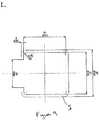
Figures 1a and 1b are isometric and perspective views from, respectively, the foot and head ends of a patient support apparatus including a deck support frame embodying the present invention;Figure 2 is side view of the patient support apparatus offigure 1 with the patient support deck in a lowered position;Figure 3 is a view similar to that offigure 2 but with the patient support deck in a lowered position;Figure 4 is a detailed view of a section through the top of one of leg assemblies of the apparatus infigure 1 ;Figure 5 is an end view of an alternative embodiment of the invention having a braking mechanism, in which the deck support frame is at its lowermost position and the brake engaged;Figure 6 is a detailed view of portion VI offigure 5 ;Figure 7 is a perspective view corresponding to the view offigure 6 ;Figures 8a and 8b are diagrams setting out roller dimensions (in mm) for an embodiment of the invention;Figure 9 is a diagram setting out dimensions (in mm) for a channel element suitable for use with the roller offigures 8a and 8b ; andFigure 10 is a diagram setting out dimensions (in mm) for a suitable brake lever and channel element.- Hospital beds typically include a deck supporting a mattress or other patient support element (not shown in figures). The deck may be divided into articulated sections so as to create various seating and lying down configurations. Articulated beds with a controllable articulation system for the patient support surface are known and are not a novel and inventive part of embodiments of the subject invention so will not be described in detail. An example of such an articulated patient support surface is shown in
EP 2 181 685WO 2004/021952 to which reference should now be made and whose contents are included herein by way of reference. - Referring to
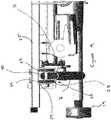
Figures 1 to 3 , a hospital bed support assembly embodying the invention includes adeck support frame 3 to which a headboard and a footboard may be mounted at, respectively, itshead 4 andfoot 5 ends. The head board is mountable onhead board plates 33 and the foot board onfoot board plates 34 .The deck support frame has two leg orsupport structures 6 pivotally mounted to its under surface. Each of the leg structures orassemblies 6 includes a pair oflegs 7 each coupled to thedeck support frame 3 by a moveable upper pivot or guide element 8 at their deck or upper end 9. The moveable upper guide elements can move parallel to the longitudinal axis of the deck frame. For example, the moveable upper guide element 8 of the left-hand leg inFigures 2 and3 can move in the directions shown by arrows D1 and D2 . - The lower portions of the
legs 7 of each pair of legs are connected together by alower bracing cross-element 10 at the bottom 12 of the legs. Thelower cross-elements 10 are each in turn connected to a lower longitudinal or side element and able to rotate about their longitudinal axis. In the embodiment shown infigures 1 to 3 , each end of the foot end leg assembly lower cross-element is pivotally connected to a lower portion of a respective length extension element and the upper portion of each length extension element is pivotally connected to the lower longitudinal side element. The foot and head ends of thelower side elements 35 each have a castor orcastor device 14 so that the support assembly can move over a floor or surface on which it is placed. - A pair of
stabilizer elements 16 are connected to each pair of legs. A stabilizer element is connected to and links each leg to the underside of the deck support frame. Thestabilizer elements 16, which are each coupled to aleg 7, are pivotally connected at their firstupper ends 17 to the underside of thedeck support frame 3. Theupper ends 17 of each stabilizer are connected to a fixed upper pivot 18 displaced from the leg upper moveable pivot 8 of the respective leg, and are pivotally connected at their secondlower ends 19 to the respective pair of legs at a pair of respectivelower stabilizer pivots 20. - A
stabilizer cross-element 37 is pivotally connected between the pair ofstabilizers 16 for each leg assembly. The respective stabilizer cross-element is connected to each respective stabilizer at a point 36 between its upper 17 and lower 19 ends. - An actuator-
stabilizer yoke 21 is connected to each stabilizer cross-element at a point substantially mid-way along the stabilizer cross-element so that it is in the middle of the bed. The actuator-stabilizer yoke 21 is pivotally coupled to an end of an actuator 22 (which may be an hydraulic actuator) which controllably extends and retracts anactuator rod 23 connected to the actuator-stabilizer yoke 21. Extension and retraction of theactuator rod 23 causes therespective stabilizer cross-element 37 and hence the pair ofstabilizers 16 connected to thatstabilizer cross-element 37 to move and thence the pair oflegs 7 connected to thatstabilizer 16 to rotate relative to thedeck support frame 3 and thence raises or lowers thedeck support frame 3 and the patient support surface arranged on that deck support frame. Theactuators 22 may be controlled by either the patient or a care-giver. Control mechanisms for such actuators are well known and may be either a foot operated pedal, control panel on the side of the bed, remote control or other control mechanism. Suitable actuators are well known and are therefore not described in detail in this application. They may be hydraulic, electric or pneumatic. An example of hydraulic actuators controlling the height of a deck is described inEP 2 181 685WO 2004/021952 . - Referring to
figure 1 , thedeck support frame 3 is formed by three sides of a rectangle and comprisesparallel side elements 24 connected at their head ends by ahead frame element 25. In the described embodiment there is no foot frame element closing the rectangle other than the foot board (not shown) when that is attached to the foot board plates 34 (not shown) but one could be provided if appropriate. One of the known patient support deck arrangements such as that described inEP 2 181 685WO 2004/021952 may be secured to the patient support frame. - As shown in, for example,
figure 4 , the side rail elements each comprise a hollow channel element open, along at least a portion of its length, on its lower side 27. The channel element is a modified inverted U-shaped channel in which a portion of thebottom edges 28 are lipped such that the sides of the channel extend partially across the bottom of the inverted U-shaped channel. - The upper end of each leg is connected to two
rollers 29. Therollers 29 are supported onaxles 30 running through theleg 7 and can rotate relative to theleg 7. Theupper end 31 of each leg passes through the gap or space 32 in the bottom of thechannel elements 24 defining the sides of the deck support frame. Therollers 29 each engage the inner surface of the channel element. - Referring to
figures 2 and3 , when theactuators 22 extend theirrespective rods 23 together to move thedeck support frame 3 from a lowered position (seefigure 3 ) to a raised position (seefigure 2 ), the stabiliser element moves in direction E and pivots about its upper pivot. At the same time, the leg element pivots in direction F with its respective guide element moving in direction D1. As the guide element moves in direction D1 while the deck support surface is being raised, the respective set ofrollers 29 roll relative to therespective channel element 24. - When the
actuators 22 retract theirrespective rods 23 together to move the deck support surface from a raised position (figure 2 ) to a lowered position (figure 3 ), the stabiliser element moves in direction G and pivots about its upper pivot. At the same time, the leg element pivots in direction H with its respective guide element moving in direction D2. As the guide element moves in direction D2 while the deck support surface is being raised, the rollers roll relative to the channel element. - Movement of the
legs 7 and associatedrollers 29 brought about by extension of the actuator rod to raise the deck support frame pushes the rollers against the inner surface of the top of therespective channel element 24 so the roller rolls against that inner top surface of the channel. When the deck support frame is lowered by retraction of the actuator rod, the weight of the deck support frame and the patient support surface and patient supported thereon presses the inner top surface of thechannel 24 against the respective rollers so that again the rollers roll along that top inner surface. - The
channel 24 is provided along a substantial part of its length with alip portion 28 welded or otherwise attached to each of the bottom edges of the two sides of the channel element. This helps hold the rollers in place and, if the patient support deck is lifted manually or otherwise than using the actuators, pushes up against the bottom of the rollers such that they roll against the lipped bottom edges 28. - Moving the deck support frame into the Trendelenburg position or reverse Trendelenburg position is not illustrated in the figures. However, it is achieved by having one of the leg assemblies in the raised position and the other in the lowered position and is otherwise the same as for lowering or raising the whole height of a substantially horizontal deck support frame. For the Trendelenburg position the foot end is raised to be about 15-30 degrees above the head end, whereas in the reverse Trendelenburg the head end is raised to be above the foot end.
- In a preferred embodiment of the patient support apparatus embodying the intention, at least one of the castors and/or castor devices at each of the foot and head ends of the apparatus are provided with a brake assembly with a brake lever as described in, for example,
US 7,703,157 and arranged to be contacted and pressed down by the lower surface of the channel element to lock or brake the respective caster or caster device when the respective portion of the deck support frame is lowered. - Each of the castors includes a braking mechanism.
Figures 5b show how a braking mechanism of the type used in castors of the type supplied by Tente as parts reference 5944 USC125 R36 may be incorporated in an embodiment of the invention. In such castors, thecastor wheels 38 are braked when apliable braking element 39 is squeezed down by abraking surface 40 so that the sides of the braking element contact and push against the sides of the castor wheels. An alternative braking element is shown inUS 7,703,157 in which braking is by means of a floor engaging element which is pushed into contact with the floor when the braking surface is ousted downwards. Any castor with an actuator mechanism operable by being pressed down or contacted may be used. - The
braking surface 40 at the foot ends of the bed is pushed downward by the action of abraking lever 41 which may be actuated by, for example, the foot of a care giver on, as is shown infigures 5 to 7 , by contact with the underside of thechannel element 24 as the bed is lowered to the lowermost position. The use of a guide element 8 which moves inside achannel 24 allows one to position thelongitudinal channel 24 closes to the edges of the bed than is possible with the previous arrangements with a guide element on the outside of a channel. This means that the channel orlongitudinal rod 24 can be positioned so it moves in a place sufficiently close to the wheels to directly engage thebrake lever 41. - The brakes surfaces (not shown) of the head and castors are connected to a respective foot end braking levers 41 by a rod element running inside each of the
lower rail elements 35. Movement of thebraking lever 41 causes the rod to rotate and hence push the braking surfaces associated with the head end castors to move and hence brake or release the head end castors.
Claims (10)
- A person support apparatus comprising:a person support frame (3) for supporting a person support deck, the person support frame having two sides (24) extending between a head end (4) and a foot end (5); anda support assembly for supporting the person support frame (3) and moving it relative to a floor surface,
whereinthe support assembly comprises at least one leg assembly (6) pivotally coupled at a first upper end portion to the person support frame (3) and coupled at its second lower end portion to floor engaging means (19), and an actuator element (22, 23) operable to move the leg assembly and thereby move the person support frame relative to the floor whereby at least one of the sides of the person support frame comprises an inverted substantially U-shaped channel element (24) having a substantially continuous upper surface, two substantially continuous side surfaces connected at their top edges to the upper surface, and a downward facing opening between the bottom edges of the two side surfaces,characterised in that the first upper end portion of the leg assembly includes a guide element (29, 30) arranged to contact and run along an inner surface of the top of the channel element. - Apparatus according to claim 1 wherein the guide element comprises a roller assembly (29, 30) arranged to run inside the channel element (24) and engage and run along a channel between the bottom of the upper surface of the channel element and the bottom of the channel element.
- Apparatus according to any preceding claim wherein the lower edge of at least one of the side surfaces has a lipped portion (28) projecting partially across the bottom of the channel to partially close the open bottom side of the channel element,
- Apparatus according to claim 3 wherein the lower edges of both side surfaces include lipped portions (28) projecting partially across the open bottom side of the channel element.
- Apparatus according to any preceding claim wherein the roller assembly (29, 30) is supported on a surface of the upper end portion of the leg assembly (6) and an upper portion (31) of the leg assembly extends through the bottom open side of the channel element (24) and into the channel element.
- Apparatus according to claim 2, or any of claims 3 to 5 when dependent on claim 2, wherein a pair of roller assemblies (29) are supported on the leg assembly with one roller on a first side of the leg assembly and the other on an opposite side, the rollers each being arranged to run inside the channel element and engage and run along the channel between the top surface of the opposing lipped portions and the bottom of the upper surface.
- Apparatus according to any preceding claim wherein the floor engaging means includes a fixing brake (39, 40, 41) for fixing the position of the floor engaging element relative to a floor, the fixing brake comprising an actuator (40, 41) adapted to be moved between a braking position and a release position and wherein the actuator is arranged to be engaged by a lower surface of the channel element (24) as the respective leg assembly reaches its lowermost position and thereby automatically brake the floor engaging means as the leg assembly reaches its lowermost position.
- Apparatus according to claim 7 wherein the floor engaging means is a castor device (14).
- Apparatus according to any of claims 7 to 8 comprising floor engaging means at each of the foot and head ends of the apparatus and wherein the actuator comprises a lever (41) at the foot end of the apparatus, the lever (41) being coupled to the floor engaging means (14) on both the foot end leg assembly and the head end assembly so as to automatically brake floor engaging means on both the foot end and head end as the leg assembly reaches its lowermost assembly.
- Apparatus according to claim 9 wherein the apparatus includes at least one lower longitudinal side frame element (35) coupled to a lower portion of the leg assembly and including floor engaging means at its foot and head ends, and wherein the lever (41) at the foot end is coupled to the head end floor engaging means by a rotatable rod extending along or inside the lower longitudinal side frame element (35).
Priority Applications (3)
| Application Number | Priority Date | Filing Date | Title |
|---|---|---|---|
| EP13193375.6AEP2873400B1 (en) | 2013-11-18 | 2013-11-18 | Person support apparatus |
| US14/540,185US9089459B2 (en) | 2013-11-18 | 2014-11-13 | Person support apparatus |
| US14/718,436US20150250665A1 (en) | 2013-11-18 | 2015-05-21 | Person support apparatus having frame actuated castor brake |
Applications Claiming Priority (1)
| Application Number | Priority Date | Filing Date | Title |
|---|---|---|---|
| EP13193375.6AEP2873400B1 (en) | 2013-11-18 | 2013-11-18 | Person support apparatus |
Publications (2)
| Publication Number | Publication Date |
|---|---|
| EP2873400A1 EP2873400A1 (en) | 2015-05-20 |
| EP2873400B1true EP2873400B1 (en) | 2018-01-31 |
Family
ID=49639732
Family Applications (1)
| Application Number | Title | Priority Date | Filing Date |
|---|---|---|---|
| EP13193375.6ANot-in-forceEP2873400B1 (en) | 2013-11-18 | 2013-11-18 | Person support apparatus |
Country Status (2)
| Country | Link |
|---|---|
| US (2) | US9089459B2 (en) |
| EP (1) | EP2873400B1 (en) |
Families Citing this family (11)
| Publication number | Priority date | Publication date | Assignee | Title |
|---|---|---|---|---|
| US9999558B2 (en) | 2011-04-11 | 2018-06-19 | Usine Rotec Inc. | Piece of furniture, such as an adjustable bed, having an adjustable platform |
| PL2696833T3 (en) | 2011-04-11 | 2018-03-30 | Usine Rotec Inc. | A piece of furniture, such as an adjustable bed, having an adjustable platform |
| US8800080B2 (en)* | 2011-09-01 | 2014-08-12 | Drive Medical Design & Mfg. | Long term care bed |
| DE102014205842B4 (en)* | 2014-03-28 | 2020-07-09 | Siemens Healthcare Gmbh | Movement device for moving an object, patient couch and method for operating a movement device |
| US9402773B2 (en)* | 2014-05-12 | 2016-08-02 | Gillette Children's Specialty Healthcare | Prone cart |
| CA2902102C (en)* | 2014-08-27 | 2023-02-14 | Umano Medical Inc. | Systems for patient support surface orientation and displacement |
| US9994072B2 (en)* | 2014-09-17 | 2018-06-12 | Medical Depot, Inc. | Patient care bed |
| US10426680B2 (en) | 2015-07-31 | 2019-10-01 | Hill-Rom Services, Inc. | Air bladder control of mattress/frame width expansion |
| US10507856B1 (en)* | 2017-12-08 | 2019-12-17 | Simon Malson | Transport cart with reclining chairs |
| TWM559120U (en)* | 2018-02-01 | 2018-05-01 | Ulife Healthcare Inc | Electric furniture bed |
| CA3044312A1 (en) | 2018-05-28 | 2019-11-28 | Donald W. Wright | Sling for use in moving persons with limited mobility |
Family Cites Families (312)
| Publication number | Priority date | Publication date | Assignee | Title |
|---|---|---|---|---|
| US595734A (en) | 1897-12-21 | Invalid-bed bottom | ||
| US2734104A (en) | 1956-02-07 | gollhofer | ||
| US598054A (en) | 1898-01-25 | meant | ||
| US585834A (en) | 1897-07-06 | Mattress | ||
| US1017153A (en) | 1910-11-26 | 1912-02-13 | John F Kampe | Bed-protector. |
| US1043370A (en) | 1912-02-12 | 1912-11-05 | William R Stubbs | Wall-protector. |
| US1261040A (en) | 1917-04-19 | 1918-04-02 | Samuel Lanes | Combined chair and bed. |
| US1398203A (en) | 1921-02-19 | 1921-11-22 | Henry A Schmidt | Convertible bed-spring |
| US1440783A (en) | 1922-04-13 | 1923-01-02 | Kiley Thomas | Wall-protecting stop |
| US2245909A (en) | 1937-10-19 | 1941-06-17 | Enfiajian Helen | Cushioning and supporting device |
| US2281209A (en) | 1938-07-29 | 1942-04-28 | Smith Orville Dale | Combination bed and carriage |
| US2452366A (en) | 1944-08-11 | 1948-10-26 | Robert R Freund | Patient adjustable foot section for articulated beds |
| US2500742A (en) | 1945-07-30 | 1950-03-14 | Marvel Beem | Invalid's bed |
| US2477400A (en) | 1945-10-15 | 1949-07-26 | Beem Foundation | Invalid's bed |
| US2556591A (en) | 1946-02-06 | 1951-06-12 | Walter M Loxley | Invalid bed |
| US2605151A (en) | 1949-03-23 | 1952-07-29 | Shampaine Hyman Robert | Obstetrical and delivery operating table |
| US2564083A (en) | 1949-04-21 | 1951-08-14 | Alfred H W Stechert | Invalid's bed with manual control |
| US2687536A (en) | 1950-02-23 | 1954-08-31 | Roy G Miller | Adjustable bed |
| US2722017A (en) | 1951-11-16 | 1955-11-01 | Hill Rom Co Inc | Side guards for hospital beds |
| US2766463A (en) | 1952-02-19 | 1956-10-16 | Bendersky Sadie | Means for converting a bed to a chair |
| US2719769A (en) | 1952-09-04 | 1955-10-04 | Owen K Murphy | Table type of motor operated kinesitherapy device |
| US2869614A (en) | 1955-05-25 | 1959-01-20 | Floyd B Wamsley | Combination wheel chair and stretcher |
| US3010121A (en) | 1957-04-12 | 1961-11-28 | Roy Frederick Thompson | Adjustable support device |
| US3036314A (en) | 1957-06-27 | 1962-05-29 | Justin J Wetzler | Adjustable bed |
| US3003160A (en) | 1958-12-01 | 1961-10-10 | Goodman Robert | Foldable bed frame-bed to contour chair |
| US3053568A (en) | 1960-02-05 | 1962-09-11 | Clarence A Silva | Chair-bed combination |
| US3099440A (en) | 1960-09-26 | 1963-07-30 | Ritter Co Inc | Apparatus for controlling the flow of fluids |
| US3138805A (en) | 1961-04-11 | 1964-06-30 | Salvatore J Piazza | Bed-wheelchair |
| US3233255A (en) | 1961-05-22 | 1966-02-08 | Miller Herman Inc | Bed construction |
| US3112500A (en) | 1961-05-24 | 1963-12-03 | Benjamin R F Macdonald | Hospital bed |
| US3210779A (en) | 1961-09-11 | 1965-10-12 | Ted E Herbold | Multiple position combination chair-bed |
| US3239853A (en) | 1962-01-15 | 1966-03-15 | Benjamin R F Macdonald | Convertible hospital bed-chair |
| US3195151A (en) | 1962-02-23 | 1965-07-20 | Russell I Boyer | Hospital bed footboard and clamp therefor |
| US3309717A (en) | 1963-03-20 | 1967-03-21 | American Seating Co | Hospital bed |
| US3220022A (en) | 1963-12-23 | 1965-11-30 | Nelson Ted | Hospital bed sliding foot section |
| US3220021A (en) | 1964-04-09 | 1965-11-30 | Nelson Ted | Adjustable seat length hospital bed |
| US3277501A (en) | 1965-03-22 | 1966-10-11 | George E Frisz | Bed assembly |
| US3317931A (en) | 1965-08-13 | 1967-05-09 | Royalmetal Corp | Adjustable bed |
| SE300672B (en) | 1965-09-02 | 1968-05-06 | Redev Ab | |
| US3393004A (en) | 1966-10-06 | 1968-07-16 | Simmons Co | Hydraulic lift system for wheel stretchers |
| US3456269A (en) | 1967-10-16 | 1969-07-22 | Robert Goodman | Foldable bed with adjustable contour bed spring |
| US3506989A (en) | 1968-04-29 | 1970-04-21 | Dominion Metalware Ind Ltd The | Guard rail for hospital bed |
| AU430169B2 (en) | 1968-10-11 | 1972-11-15 | Hodge Investments Proprietary Limited' | Invalid chair |
| US3526008A (en) | 1968-10-21 | 1970-09-01 | Borg Warner | Latch and support assembly for bed restraining sides |
| US3593350A (en) | 1969-03-13 | 1971-07-20 | Dominion Metalware Ind Ltd The | Retractable bed |
| US3665528A (en) | 1969-08-01 | 1972-05-30 | Trioteam As | Adjustable bed |
| DE1942495C2 (en) | 1969-08-21 | 1971-11-04 | Grundig Emv | FOOT SWITCH FOR A DICTING DEVICE IN PARTICULAR MAGNETIC TAPE DEVICE |
| US3585659A (en) | 1969-10-15 | 1971-06-22 | Hill Rom Co Inc | Safety side guard for hospital beds |
| US3598947A (en) | 1969-11-03 | 1971-08-10 | Osborn Engineering Corp | Pedal operated control for electric fishing motors |
| US3611452A (en)* | 1970-06-25 | 1971-10-12 | American Hospital Supply Corp | Invalid bed construction |
| US3905591A (en) | 1970-09-24 | 1975-09-16 | Siemens Ag | Patient{3 s couch |
| DE2134061A1 (en) | 1971-07-08 | 1973-01-25 | Bosch Gmbh Robert | HYDRAULIC CONTROL DEVICE |
| GB1341325A (en) | 1971-07-09 | 1973-12-19 | Scales J T | Inflatable support appliance |
| GB1436548A (en) | 1972-06-07 | 1976-05-19 | Matburn Holdings Ltd | Surgical operation tables |
| US3814414A (en) | 1972-07-24 | 1974-06-04 | H Chapa | Medical examination table |
| DE2406374A1 (en) | 1973-02-14 | 1975-08-14 | Fritz Kerstholt | Divan with adjustable outer parts - has bearing spring arrangement operated by body weight and locked manually |
| GB1444802A (en) | 1973-03-06 | 1976-08-04 | ||
| US3897973A (en) | 1973-06-05 | 1975-08-05 | Amerco Inc | Blood drawing chair |
| US3972081A (en) | 1973-08-20 | 1976-08-03 | Affiliated Hospital Products, Inc. | Bed arrangement |
| US3893197A (en) | 1974-02-11 | 1975-07-08 | Maurine E Ricke | Hospital bed footboard assembly |
| US3932903A (en) | 1974-10-04 | 1976-01-20 | Hill-Rom Company, Inc. | Guard including electrical controls and slidable underneath the bed |
| GB1466080A (en) | 1974-10-30 | 1977-03-02 | Siddall Hilton Ltd | Hospital bed attachments |
| JPS5524893B2 (en) | 1975-02-08 | 1980-07-02 | ||
| US3977664A (en) | 1975-03-25 | 1976-08-31 | Affiliated Hospital Products, Inc. | Hydraulic control valve arrangement for operating tables and the like |
| DE2538411C3 (en) | 1975-08-29 | 1980-07-24 | Binz Gmbh & Co, 7073 Lorch | Stretcher storage frame with liftable, spring-loaded stretcher platform |
| US4103376A (en) | 1975-10-29 | 1978-08-01 | Interroyal Corporation | Safety side for hospital bed |
| JPS5264594A (en) | 1975-11-21 | 1977-05-28 | Hitachi Ltd | Torus type nuclear fusion device |
| US4016613A (en) | 1975-11-24 | 1977-04-12 | Interroyal Corporation | Balanced bumper means for furniture |
| US4038709A (en) | 1975-12-24 | 1977-08-02 | Kerwit Medical Products, Inc. | Dual hydraulic hospital bed |
| US4205665A (en) | 1976-05-05 | 1980-06-03 | Burton Charles V | Gravity lumbar reduction method |
| US4258445A (en) | 1976-07-15 | 1981-03-31 | Zur Henry C | Beds and adjustable body supporting assemblies |
| US4127906A (en) | 1976-07-15 | 1978-12-05 | Zur Henry C | Adjustable bed-chair |
| US4293746A (en) | 1977-02-07 | 1981-10-06 | Braaten Ronald J | Foot operated control unit |
| DE2705575C3 (en) | 1977-02-10 | 1979-09-20 | Siemens Ag, 1000 Berlin Und 8000 Muenchen | Walkable step switch device |
| GB1595417A (en) | 1977-03-29 | 1981-08-12 | Welch H G | Beds and mattresses |
| US4139917A (en) | 1977-10-17 | 1979-02-20 | Loel Fenwick | Labor, delivery and patient care bed |
| EG13053A (en) | 1977-10-18 | 1980-03-31 | Hana Wasfi | Anti-sore bed |
| US4168099A (en) | 1978-03-27 | 1979-09-18 | Midmark Corporation | Multi-position examination chair |
| GB2018221B (en) | 1978-04-01 | 1982-04-21 | Nesbit Evans & Co Ltd | Adjustable hospital beds |
| US4195829A (en) | 1978-04-21 | 1980-04-01 | Sybron Corporation | Surgical table hydraulic system |
| US4183109A (en) | 1978-04-21 | 1980-01-15 | Howell William H | Sectional bed |
| US4225989A (en) | 1978-10-05 | 1980-10-07 | Glynwed Group Services Limited | Inflatable supports |
| US4231030A (en) | 1979-01-23 | 1980-10-28 | Weiss Mary G | Safety device for a crib |
| US4240169A (en) | 1979-01-26 | 1980-12-23 | Roos Kjell E | Patient transferring apparatus |
| NL7901576A (en) | 1979-02-28 | 1980-09-01 | Philips Nv | PATIENT CARRIER WITH TILTABLE CARRIERS. |
| NL7909210A (en) | 1979-12-20 | 1981-07-16 | Vredestein Nv | MATTRESS ASSEMBLY. |
| US4336621A (en) | 1980-02-25 | 1982-06-29 | Schwartz Donald R | Disposable orthopedic overmattress for articulated beds |
| US4332042A (en) | 1980-03-31 | 1982-06-01 | Burlington Industries, Inc. | Geriatric environmental systeming |
| US4361917A (en) | 1980-04-03 | 1982-12-07 | Wilson Harold L | Portable orthopedic bed |
| US4259762A (en) | 1980-04-07 | 1981-04-07 | Gennaro Civitelli | Shock-absorbing hinge-pin doorstop |
| US4345344A (en) | 1980-04-08 | 1982-08-24 | Centre De Recherche Industrielle Du Quebec | Hospital bed |
| DE3017245A1 (en) | 1980-05-06 | 1981-11-12 | Ritter Ag, 7500 Karlsruhe | ADJUSTMENT DEVICE FOR CONTROLLING THE OPERATING DENTAL INSTRUMENTS |
| US4425673A (en) | 1980-12-01 | 1984-01-17 | B-W Health Products, Inc. | Lifting system for adjustable hospital bed |
| US4638516A (en) | 1981-01-19 | 1987-01-27 | Kinetic Concepts, Inc. | Therapeutic bed support |
| US4409695A (en) | 1981-02-03 | 1983-10-18 | Burke, Inc. | Adjustable bed for morbidly obese patients |
| US4411035A (en) | 1981-03-30 | 1983-10-25 | Loel Fenwick | Maternity care bed |
| US4386254A (en) | 1981-06-15 | 1983-05-31 | Timex Corporation | Rocker switch |
| US4472845A (en) | 1981-09-01 | 1984-09-25 | B-W Health Products, Inc. | Latching system for adjustable motorized hospital bed |
| US4435862A (en) | 1981-10-19 | 1984-03-13 | Simmons Universal Corporation | Control arrangement and method for an adjustable bed |
| US4494259A (en) | 1981-11-25 | 1985-01-22 | Simmons Universal Corporation | Adjustable bed |
| US4453732A (en) | 1981-12-24 | 1984-06-12 | Assanah Albert A | Patient transport and care vehicle |
| FR2523437A1 (en) | 1982-03-18 | 1983-09-23 | Idetec Entreprise | MEDICAL BED |
| US4539560A (en) | 1982-12-10 | 1985-09-03 | Hill-Rom Company, Inc. | Bed departure detection system |
| JPS5993524U (en) | 1982-12-15 | 1984-06-25 | 狩野 千世子 | Air mat type bed operated by computer |
| DE8320066U1 (en) | 1983-07-12 | 1983-12-01 | Siemens AG, 1000 Berlin und 8000 München | Slide switch |
| US4586492A (en) | 1983-08-08 | 1986-05-06 | Manahan Antonio P | Therapeutic bed |
| DE3464696D1 (en) | 1983-08-17 | 1987-08-20 | Moelnlycke Ab | A chair and/or bed arrangement |
| US4545084A (en) | 1984-02-03 | 1985-10-08 | Joerns Healthcare, Inc. | Modular drive arrangement for adjustable beds and the like |
| US4612679A (en) | 1984-03-01 | 1986-09-23 | Amedco Health Care Inc. | Bed side guard assembly |
| US4617690A (en) | 1985-01-07 | 1986-10-21 | Whittaker Corporation | Inflatable bed patient mattress |
| US4625345A (en) | 1985-03-26 | 1986-12-02 | Wood Lorin A | Automated sofa bed |
| US4776047A (en) | 1985-05-07 | 1988-10-11 | Med Bed Technologies, Inc. | Multiple function invalid bed arrangement |
| US4685159A (en) | 1985-05-09 | 1987-08-11 | Hans Oetiker | Hospital bed |
| US4858481A (en) | 1985-05-13 | 1989-08-22 | Brunswick Valve & Control, Inc. | Position controlled linear actuator |
| US4769584A (en) | 1985-06-18 | 1988-09-06 | Thomas J. Ring | Electronic controller for therapeutic table |
| US4680790A (en) | 1985-08-22 | 1987-07-14 | Joerns Healthcare, Inc. | Bedside control module for healthcare stations and the like |
| NL8502789A (en) | 1985-10-11 | 1987-05-04 | Auping Bv | MATTRESS. |
| US4745647A (en) | 1985-12-30 | 1988-05-24 | Ssi Medical Services, Inc. | Patient support structure |
| US4768249A (en) | 1985-12-30 | 1988-09-06 | Ssi Medical Services, Inc. | Patient support structure |
| US4653129A (en) | 1986-04-25 | 1987-03-31 | Midmark Corporation | Side rail assembly for a wheeled stretcher |
| US4797962A (en) | 1986-11-05 | 1989-01-17 | Air Plus, Inc. | Closed loop feedback air supply for air support beds |
| YU46743B (en) | 1986-12-02 | 1994-04-05 | Milenko Pupović | BED WITH ADJUSTABLE POSITIONS |
| US4912787A (en) | 1987-03-30 | 1990-04-03 | Beta Medical Products | Hydraulic stretcher device |
| US4724555A (en) | 1987-03-20 | 1988-02-16 | Hill-Rom Company, Inc. | Hospital bed footboard |
| US4751754A (en) | 1987-04-02 | 1988-06-21 | Hill-Rom Company, Inc. | Dual hydraulic hospital bed with emergency bypass circuit |
| US4862530A (en) | 1987-07-27 | 1989-09-05 | Chen Chung C | Convertible bed |
| US4974905A (en) | 1987-08-10 | 1990-12-04 | Davis John W | Chair bed |
| US4856123A (en) | 1987-09-24 | 1989-08-15 | Henderson Medical Appliance Company Ltd. | Toilet apparatus for use by bed ridden patients |
| US4811435A (en) | 1988-01-15 | 1989-03-14 | Hill-Rom Company, Inc. | Hospital bed with pivoting headboard |
| IL85442A (en) | 1988-02-17 | 1992-11-15 | Oded Sheinfeld | Combined bed and relaxation chair |
| US4949410A (en) | 1988-03-11 | 1990-08-21 | Hausted, Inc. | Guard rail for patient transport apparatus hospital beds and the like |
| US4858260A (en) | 1988-03-11 | 1989-08-22 | Hausted, Inc. | Patient transport apparatus including Trendelenburg mechanism and guard rail |
| US5802640A (en) | 1992-04-03 | 1998-09-08 | Hill-Rom, Inc. | Patient care system |
| WO1989009590A1 (en) | 1988-03-23 | 1989-10-19 | Robert Ferrand | Patient support system |
| US4953247A (en) | 1988-05-09 | 1990-09-04 | Hasty Charles E | Air-operated body support device |
| US4821470A (en) | 1988-06-17 | 1989-04-18 | Hill-Rom Company, Inc. | Head wall for hospital bed |
| US5060425A (en) | 1988-06-17 | 1991-10-29 | Hill-Rom Company, Inc. | Head wall for hospital bed |
| NL8801644A (en) | 1988-06-28 | 1990-01-16 | Applied Power Inc | HYDRAULIC CONTROL UNIT, PARTICULARLY FOR LIFTING A LOAD LIKE A HOSPITAL BED. |
| US4862529A (en) | 1988-07-13 | 1989-09-05 | Hill-Rom Company, Inc. | Hospital bed convertible to chair |
| US4894876A (en) | 1988-07-15 | 1990-01-23 | Hill-Rom Company, Inc. | Multipurpose maternity care bed |
| JPH02109563A (en) | 1988-10-19 | 1990-04-23 | Paramaunto Bed Kk | Lifting mechanism of floor support frame |
| JPH02154760A (en) | 1988-12-06 | 1990-06-14 | Paramaunto Bed Kk | Lifting mechanism of floor support frame |
| JPH02156950A (en) | 1988-12-09 | 1990-06-15 | Paramaunto Bed Kk | Raising/lowering and tilting mechanism for floor part supporting frame |
| JPH02200262A (en) | 1989-01-31 | 1990-08-08 | Paramaunto Bed Kk | Elevating/lowering mechanism for floor part supporting frame in laying stand and laying stand equipped with elevating/lowering mechanism |
| FR2646599A1 (en) | 1989-05-05 | 1990-11-09 | Howard Stanley Weight | SUPPORT SURFACE, IN PARTICULAR FOR A HOSPITAL BED |
| EP0403073A3 (en) | 1989-05-12 | 1991-07-24 | Patreen Associates Limited | A bed |
| US4951032A (en) | 1989-06-15 | 1990-08-21 | Langsam Andrew S | Crib rail safety annunciator |
| US5054141A (en) | 1989-07-28 | 1991-10-08 | Hill-Rom Company, Inc. | Hospital bed having a Y-shaped base |
| US5179744A (en) | 1989-07-28 | 1993-01-19 | Hill-Rom Company, Inc. | Hospital bed with inflatable and collapsible side edges and laterally-movable side guards |
| US5083332A (en) | 1989-07-28 | 1992-01-28 | Hill-Rom Company, Inc. | Hospital bed with collapsible side edges and laterally-movable side guards |
| US4985946A (en) | 1989-07-28 | 1991-01-22 | Hill-Rom Company, Inc. | Hospital bed adapted for use with a C-arm |
| US5077843A (en) | 1990-07-28 | 1992-01-07 | Hill-Rom Company, Inc. | Hospital bed and assemblies of hospital care apparatus |
| US5022105A (en)* | 1989-08-04 | 1991-06-11 | Michael Catoe | Mobile lift-assisted patient transport device for field use |
| US4953243A (en) | 1989-08-09 | 1990-09-04 | Amedco Health Care, Inc. | Electronic control with emergency CPR feature for adjustable bed |
| DE3927484C1 (en)* | 1989-08-19 | 1990-10-04 | Stollenwerk Fabrik Fuer Sanitaetsausruestungen Hans Stollenwerk & Cie Gmbh & Co, 5000 Koeln, De | |
| JPH03155862A (en) | 1989-11-14 | 1991-07-03 | Paramaunto Bed Kk | Elevation mechanism for floor part supporting frame in dorsal stand and dorsal stand provided with the same |
| JPH03186212A (en) | 1989-12-18 | 1991-08-14 | Paramaunto Bed Kk | Elevating mechanism for floor board in bed |
| JPH07110253B2 (en) | 1989-12-22 | 1995-11-29 | パラマウントベッド株式会社 | Floor liftable bed with extendable floor |
| JPH03237976A (en) | 1990-02-16 | 1991-10-23 | Paramaunto Bed Kk | Lift operation mechanism of transfer bed |
| US5063624A (en) | 1990-05-08 | 1991-11-12 | Stryker Corporation | Manual/electric twin jack bed |
| US5479666A (en) | 1994-01-25 | 1996-01-02 | Hill-Rom Company, Inc. | Foot egress chair bed |
| US5454126A (en) | 1994-01-25 | 1995-10-03 | Hill-Rom Company, Inc. | Foot egress chair bed |
| US5370111A (en) | 1990-05-16 | 1994-12-06 | Hill-Rom Company, Inc. | Mobile ventilator capable of nesting within and docking with a hospital bed base |
| US5117521A (en) | 1990-05-16 | 1992-06-02 | Hill-Rom Company, Inc. | Care cart and transport system |
| US5577279A (en) | 1990-05-16 | 1996-11-26 | Hill-Rom Company, Inc. | Hospital bed |
| US5105486A (en) | 1990-06-18 | 1992-04-21 | Joerns Healthcare Inc. | Adjustable bed |
| US5040253A (en) | 1990-07-16 | 1991-08-20 | Cheng Yen Feng | Variable bed having multiple functions |
| US5035014A (en) | 1990-08-10 | 1991-07-30 | Ssi Medical Services, Inc. | Comfort guard for low air loss patient support systems |
| US5083334A (en) | 1990-10-12 | 1992-01-28 | Ssi Medical Services, Inc. | Side guard for patient support |
| DE69032563T2 (en) | 1990-11-06 | 1998-12-24 | Sunrise Medical Ccg Inc., Stevens Point, Wis. | MATTRESS FILLED WITH A FLUID |
| GB2250189B (en) | 1990-11-28 | 1993-11-24 | Nesbit Evans & Co Ltd | Beds |
| US5129117A (en) | 1990-11-28 | 1992-07-14 | Hill-Rom Company, Inc. | Birth assist protection guard |
| USD336577S (en) | 1990-12-17 | 1993-06-22 | Hill-Rom Company, Inc. | Sideguard for a birthing bed |
| US5074000A (en) | 1991-01-11 | 1991-12-24 | Ssi Medical Services, Inc. | Apparatus for performing head and foot Trendelenburg therapy |
| US5235258A (en) | 1991-03-27 | 1993-08-10 | Santino Antinori | Remotely controlled articulated bed |
| DE9103817U1 (en) | 1991-03-28 | 1991-06-27 | Dewert, Eckhart, 4904 Enger | Lifting device |
| US5072463A (en) | 1991-04-11 | 1991-12-17 | Willis William J | EZ access bed |
| US5157800A (en) | 1991-04-15 | 1992-10-27 | Hill-Rom Company, Inc. | Foot section for birthing bed |
| US5109554A (en) | 1991-04-15 | 1992-05-05 | Hill-Rom Company, Inc. | Shield for birthing bed |
| US5095561A (en) | 1991-05-09 | 1992-03-17 | Green Kenneth J | Invalid bed |
| US5193633A (en) | 1991-06-07 | 1993-03-16 | Wright State University | Motorized transfer and transport system for the disabled |
| US5148562A (en) | 1991-10-21 | 1992-09-22 | Hill-Rom Company, Inc. | Birthing bed adjustable to Trendelenburg position |
| US5269388A (en) | 1991-11-12 | 1993-12-14 | Stress-Tek, Inc. | Weighing bed |
| NL9200169A (en) | 1992-01-30 | 1993-08-16 | Schell Ind Bv | UNIVERSALLY ADJUSTABLE BED. |
| US5214360A (en) | 1992-03-13 | 1993-05-25 | Den-Tal-Ez, Inc. | Programmable adjustable chair for medical and dental applications |
| US5230113A (en) | 1992-04-14 | 1993-07-27 | Good Turn, Inc. | Multiple position adjustable day night patient bed chair |
| US5283096A (en) | 1992-04-23 | 1994-02-01 | Boston Metal Products Corp. | Resilient strip for protective strip assembly |
| US5423231A (en) | 1992-05-18 | 1995-06-13 | Siemens Aktiengesellschaft | Foot control mechanism for a dental apparatus |
| US5224228A (en) | 1992-06-17 | 1993-07-06 | Larrimore James R | Longitudinally split, motor operated butterfly bed |
| DE4320092A1 (en) | 1992-08-05 | 1993-12-23 | Helmut Koetter | Lifting framework for sick bed - use electromotor controlled by manual switch to exert compressive or tractive force for setting at desired height for nursing |
| US5267364A (en) | 1992-08-11 | 1993-12-07 | Kinetic Concepts, Inc. | Therapeutic wave mattress |
| US5216769A (en) | 1992-09-03 | 1993-06-08 | Eakin Byron C | Foldable bed |
| US5317769A (en) | 1992-11-10 | 1994-06-07 | Hill-Rom Company, Inc. | Hospital bed |
| US6131868A (en) | 1992-11-30 | 2000-10-17 | Hill-Rom, Inc. | Hospital bed communication and control device |
| DE9300438U1 (en) | 1993-01-15 | 1993-03-11 | Dewert Antriebs- und Systemtechnik GmbH & Co. KG, 4983 Kirchlengern | Lifting device |
| US5348326A (en) | 1993-03-02 | 1994-09-20 | Hill-Rom Company, Inc. | Carrier with deployable center wheels |
| US5367728A (en) | 1993-04-23 | 1994-11-29 | Chang; Ching-Lung | Adjustable ventilation mattress |
| AU674966B2 (en) | 1993-06-10 | 1997-01-16 | Desmond Corbett | Safety device |
| US5394580A (en) | 1993-06-11 | 1995-03-07 | Hill-Rom Company, Inc. | Hospital bed with three position patient side guards |
| US5398354A (en) | 1993-07-07 | 1995-03-21 | B. G. Industries, Inc. | Heel pillow mattress |
| JP2512862B2 (en) | 1993-09-08 | 1996-07-03 | パラマウントベッド株式会社 | Bottom lifting mechanism in bed |
| US5432966A (en)* | 1993-11-03 | 1995-07-18 | Ferno-Washington, Inc. | Adjustable ambulance cot with trolley mechanism |
| US5444880A (en) | 1993-11-03 | 1995-08-29 | Hill-Rom Company, Inc. | Bed with emergency head release and automatic knee down |
| DE9317308U1 (en) | 1993-11-11 | 1995-03-16 | Brugger, Klaus, Dipl.-Ing., 83700 Rottach-Egern | Hydraulic system for the hydraulic actuation of an ambulance lifting table |
| US5422521A (en) | 1993-11-18 | 1995-06-06 | Liebel-Flarsheim Co. | Foot operated control system for a multi-function device |
| US5450639A (en) | 1993-12-21 | 1995-09-19 | Hill-Rom Company, Inc. | Electrically activated visual indicator for visually indicating the mode of a hospital bed castor |
| US5715548A (en) | 1994-01-25 | 1998-02-10 | Hill-Rom, Inc. | Chair bed |
| US5687437A (en) | 1994-02-08 | 1997-11-18 | Goldsmith; Aaron | Modular high-low adjustable bed bases retrofitted within the volumes of, and cooperatively operative with, diverse existing contour-adjustable beds so as to create high-low adjustable contour-adjustable beds |
| DK0792533T3 (en) | 1994-02-28 | 1999-12-27 | Linak As | Power disconnection system for power-consuming devices such as actuators |
| DE4406784C1 (en) | 1994-03-02 | 1995-08-24 | Wissner Gmbh | Sick or care bed |
| US5537701A (en) | 1994-03-15 | 1996-07-23 | Maxwell Products, Inc. | Adjustable articulated bed |
| JP2987290B2 (en) | 1994-05-02 | 1999-12-06 | フランスベッド株式会社 | Bed equipment |
| US5611096A (en) | 1994-05-09 | 1997-03-18 | Kinetic Concepts, Inc. | Positional feedback system for medical mattress systems |
| US5542136A (en) | 1994-08-05 | 1996-08-06 | Stryker Corporation | Portable mattress for treating decubitus ulcers |
| US5579550A (en) | 1994-09-19 | 1996-12-03 | C.E.B. Enterprises, Inc. | Articulated bed with collapsible frame |
| DE69532836T2 (en) | 1994-12-23 | 2005-02-10 | Linak A/S | Threaded nut for a linear actuator |
| US5666681A (en) | 1995-01-03 | 1997-09-16 | Hill-Rom, Inc. | Heel pressure management apparatus and method |
| US6212714B1 (en) | 1995-01-03 | 2001-04-10 | Hill-Rom, Inc. | Hospital bed and mattress having a retracting foot section |
| US5542138A (en) | 1995-02-06 | 1996-08-06 | Williams; Terry N. | Bedside control unit for a hospital bed |
| JP2746295B2 (en) | 1995-04-11 | 1998-05-06 | パラマウントベッド株式会社 | Bed with floor lifting mechanism |
| US5636394A (en) | 1995-04-28 | 1997-06-10 | Stryker Corporation | Hospital bed with rack and pinion stabilizer |
| US5527097A (en) | 1995-06-02 | 1996-06-18 | Miami Metal Products, Inc. | Edging member and seating device therefore |
| US5732423A (en) | 1995-08-04 | 1998-03-31 | Hill-Rom, Inc. | Bed side rails |
| US6584628B1 (en) | 1995-08-04 | 2003-07-01 | Hill-Rom Services, Inc. | Hospital bed having a rotational therapy device |
| US5630238A (en) | 1995-08-04 | 1997-05-20 | Hill-Rom, Inc. | Bed with a plurality of air therapy devices, having control modules and an electrical communication network |
| US7017208B2 (en) | 1995-08-04 | 2006-03-28 | Hill-Rom Services, Inc. | Hospital bed |
| US5771511A (en) | 1995-08-04 | 1998-06-30 | Hill-Rom, Inc. | Communication network for a hospital bed |
| US5611094A (en) | 1995-08-24 | 1997-03-18 | M.C. Healthcare Products Inc. | Wall stop for a bed |
| US5737781A (en) | 1995-09-13 | 1998-04-14 | Ergodyne Corporation | Patient transfer system |
| US5720059A (en) | 1995-09-13 | 1998-02-24 | M.C. Healthcare Products Inc. | Tilting mechanism for bed |
| US5883615A (en) | 1995-09-29 | 1999-03-16 | Liebel-Flarsheim Company | Foot-operated control system for a multi-function |
| US5806111A (en) | 1996-04-12 | 1998-09-15 | Hill-Rom, Inc. | Stretcher controls |
| GB2313303B (en) | 1996-05-20 | 2000-04-12 | Egerton Hospital Equip | Improvements in and relating to beds |
| US5890765A (en) | 1996-06-07 | 1999-04-06 | La-Z-Boy Incorporated | Health care reclining chair |
| US5873137A (en) | 1996-06-17 | 1999-02-23 | Medogar Technologies | Pnuematic mattress systems |
| JP2825152B2 (en) | 1996-06-24 | 1998-11-18 | パラマウントベッド株式会社 | Electric drive device such as bed equipped with bottom lifting mechanism |
| CA2181021C (en) | 1996-07-11 | 2007-10-02 | Eric Laganiere | Split side guards |
| FR2751530B1 (en) | 1996-07-23 | 1998-10-23 | Support Systems International | METHOD AND DEVICE FOR SUPPORTING A PATIENT WITH A DERIVED SUPPORT HEEL AREA |
| ATE256986T1 (en) | 1996-10-23 | 2004-01-15 | Hill Rom Services Inc | INTEGRATED SIDE RAIL AND ACCESSORIES CARRYING DEVICE FOR A BED |
| US5802636A (en) | 1996-11-12 | 1998-09-08 | Hill-Rom, Inc. | Integrated siderail and accessory rail for a bed |
| US6067019A (en) | 1996-11-25 | 2000-05-23 | Hill-Rom, Inc. | Bed exit detection apparatus |
| US5808552A (en) | 1996-11-25 | 1998-09-15 | Hill-Rom, Inc. | Patient detection system for a patient-support device |
| US6240583B1 (en) | 1996-12-03 | 2001-06-05 | Hill-Rom, Inc. | Ambulatory assist arm for a bed |
| US5878452A (en) | 1996-12-03 | 1999-03-09 | Hill-Rom, Inc. | Long term care bed controls |
| DK151096A (en) | 1996-12-23 | 1998-07-17 | Linak As | Linear actuator |
| US6089593A (en) | 1997-02-10 | 2000-07-18 | Hill-Rom, Inc. | Ambulatory care chair |
| US6076208A (en) | 1997-07-14 | 2000-06-20 | Hill-Rom, Inc. | Surgical stretcher |
| US6006379A (en) | 1997-08-04 | 1999-12-28 | Patmark Company, Inc. | Articulating bed frame |
| US6021533A (en) | 1997-08-25 | 2000-02-08 | Hill-Rom, Inc. | Mattress apparatus having a siderail down sensor |
| EP1028683B1 (en) | 1997-11-07 | 2003-07-16 | Hill-Rom, Inc. | Mobile surgical support apparatus |
| US6223369B1 (en) | 1997-11-14 | 2001-05-01 | Span-America Medical Systems, Inc. | Patient support surfaces |
| GB9901221D0 (en) | 1998-12-04 | 1999-03-10 | Huntleigh Technology Plc | Bed |
| DE19803686A1 (en) | 1998-01-30 | 1999-08-05 | Siemens Ag | Method and device for the communication of equal stations of a ring-shaped, serial optical fiber bus |
| US6008598A (en) | 1998-04-22 | 1999-12-28 | Patmark Company, Inc. | Hand-held controller for bed and mattress assembly |
| US6209157B1 (en) | 1998-04-22 | 2001-04-03 | Patmark Company, Inc. | Articulating bed frame |
| US6282738B1 (en) | 1998-08-07 | 2001-09-04 | Hill-Rom, Inc. | Ob/Gyn stretcher |
| DE19900602C1 (en) | 1999-01-11 | 2000-07-13 | Wissner Bosserhoff Gmbh | Sickbed side guard with top and bottom positions swings down via axis or gearwheel guided to the belt round half circle swivel shaft using co-ordinated stop to arrest raised guard position. |
| US6290194B1 (en) | 1999-01-19 | 2001-09-18 | Hill-Rom Services, Inc. | Blower unit retention apparatus |
| US6208250B1 (en) | 1999-03-05 | 2001-03-27 | Hill-Rom, Inc. | Patient position detection apparatus for a bed |
| US6321878B1 (en) | 1999-03-05 | 2001-11-27 | Hill-Rom Services, Inc. | Caster and braking system |
| US6791460B2 (en) | 1999-03-05 | 2004-09-14 | Hill-Rom Services, Inc. | Patient position detection apparatus for a bed |
| DE19915431A1 (en) | 1999-04-06 | 2000-10-12 | Hans Ulrich Schwenk | Nursing bed; rests on support elements and has lying surface in bed frame, which is lowered, raised or tilted using support elements |
| US6178576B1 (en) | 1999-04-08 | 2001-01-30 | Jack L. Newell | Deflector attachment for an adjustable bed |
| US6352240B1 (en) | 1999-05-13 | 2002-03-05 | Hill-Rom Services, Inc. | Hydraulic control apparatus for a hospital bed |
| JP2001016234A (en) | 1999-06-29 | 2001-01-19 | Mitsubishi Electric Corp | CAN controller and one-chip computer with built-in CAN controller |
| US6260221B1 (en) | 1999-08-13 | 2001-07-17 | Marc Grabell | Medical apparatus for the treatment and prevention of heel decubitus |
| US6631431B1 (en) | 1999-09-15 | 2003-10-07 | Koninklijke Philips Electronics N.V. | Semaphore coding method to ensure data integrity in a can microcontroller and a can microcontroller that implements this method |
| US6484221B1 (en) | 1999-10-01 | 2002-11-19 | Storz Endoskop Gmbh | Bus extension for multiple masters |
| BR0016875A (en) | 1999-12-29 | 2003-06-17 | Hill Rom Services Inc | Patient support, patient-configured mattress, patient support method, method of maintaining a patient's heel pressure relief, pressure system for use with a patient support mattress, and patient support frame |
| US6751688B1 (en) | 2000-02-17 | 2004-06-15 | Ge Medical Systems Global Technology Company, Llc | Method and apparatus for safe CT scanner button presses |
| US6662391B2 (en) | 2000-02-23 | 2003-12-16 | Hi-Rom Services, Inc. | Bed latch position detector and method |
| US20010037724A1 (en) | 2000-03-08 | 2001-11-08 | Schumacher Mark S. | System for controlling hydraulic actuator |
| US6276011B1 (en) | 2000-03-17 | 2001-08-21 | Santino Antinori | Adjustable bed and adjustable frame therefor |
| US6629247B1 (en) | 2000-03-28 | 2003-09-30 | Powerware Corporation | Methods, systems, and computer program products for communications in uninterruptible power supply systems using controller area networks |
| EP1290652A2 (en) | 2000-05-05 | 2003-03-12 | Hill-Rom Services, Inc. | Hospital monitoring and control system and method |
| US6601251B2 (en) | 2000-05-30 | 2003-08-05 | Gerald S. Paul | Height adjustable medical bed including intermediate upper and lower stop positions |
| US6559783B1 (en) | 2000-08-16 | 2003-05-06 | Microchip Technology Incorporated | Programmable auto-converting analog to digital conversion module |
| US6606670B1 (en) | 2000-08-16 | 2003-08-12 | Microchip Technology Incorporated | Circuit serial programming of default configuration |
| EP1320348A2 (en) | 2000-09-29 | 2003-06-25 | Carroll Intelli Corp | Height adjustable bed and automatic leg stabilizer system therefor |
| US6735797B1 (en) | 2000-11-24 | 2004-05-18 | L&P Property Management Company | Adjustable bed system |
| DE60229868D1 (en) | 2001-08-22 | 2008-12-24 | Hill Rom Services Inc | DEVICE AND METHOD FOR CLOSING GASES IN HOSPITAL BEDS |
| US20040153583A1 (en) | 2001-09-20 | 2004-08-05 | Bartling James E. | Serial communication device with dynamic allocation of acceptance masks using serial implementation |
| US6912594B2 (en) | 2001-09-20 | 2005-06-28 | Microchip Technology Incorporated | Serial communication device with multi-mode operation of message receive buffers |
| US6944739B2 (en) | 2001-09-20 | 2005-09-13 | Microchip Technology Incorporated | Register bank |
| US7076517B2 (en) | 2001-09-20 | 2006-07-11 | Microchip Technology Incorporated | Serial communication device with dynamic filter allocation |
| CA2477724A1 (en) | 2002-03-18 | 2003-10-02 | Hill-Rom Services, Inc. | Hospital bed with controlled inflatable portion of patient support |
| WO2003088885A1 (en) | 2002-04-19 | 2003-10-30 | Hill-Rom Services, Inc. | Hospital bed obstacle detection device and method |
| US20030214953A1 (en) | 2002-05-14 | 2003-11-20 | Ge Medical Systems Global Technology Company, Llc | Networked magnetic resonance imaging system and method incorporating same |
| JP4712385B2 (en) | 2002-09-06 | 2011-06-29 | ヒル−ロム サービシーズ,インコーポレイティド | Hospital bed |
| JP2004158988A (en) | 2002-11-05 | 2004-06-03 | Nissan Motor Co Ltd | Data transmission apparatus and method, data communication system |
| US20040205111A1 (en) | 2002-11-15 | 2004-10-14 | Zaki Chasmawala | User configurable data messages in industrial networks |
| US20040142722A1 (en) | 2003-01-10 | 2004-07-22 | Everett Gregory J. | Databus communicator within a telemetry system |
| US7844657B2 (en) | 2003-01-17 | 2010-11-30 | Storz Endoskop Produktions Gmbh | System for controlling medical devices |
| US7856685B2 (en)* | 2003-03-03 | 2010-12-28 | Matunaga Manufactory Co., Ltd. | Stretcher |
| US7154991B2 (en) | 2003-10-17 | 2006-12-26 | Accuray, Inc. | Patient positioning assembly for therapeutic radiation system |
| US7013510B1 (en) | 2004-04-14 | 2006-03-21 | Raye's, Inc. | Low profile hospital bed |
| US7557718B2 (en) | 2004-04-30 | 2009-07-07 | Hill-Rom Services, Inc. | Lack of patient movement monitor and method |
| US7883478B2 (en) | 2004-04-30 | 2011-02-08 | Hill-Rom Services, Inc. | Patient support having real time pressure control |
| US6976357B1 (en) | 2004-06-23 | 2005-12-20 | Husco International, Inc. | Conduit loss compensation for a distributed electrohydraulic system |
| US7150056B2 (en)* | 2004-07-29 | 2006-12-19 | Stryker Corporation | Patient support deck lifting/lowering assembly |
| US7757318B2 (en) | 2004-09-13 | 2010-07-20 | Kreg Therapeutics, Inc. | Mattress for a hospital bed |
| US7779494B2 (en) | 2004-09-13 | 2010-08-24 | Kreg Therapeutics, Inc. | Bed having fixed length foot deck |
| US7743441B2 (en) | 2004-09-13 | 2010-06-29 | Kreg Therapeutics, Inc. | Expandable width bed |
| JP4722457B2 (en) | 2004-11-05 | 2011-07-13 | ルネサスエレクトロニクス株式会社 | CAN system |
| US7444704B2 (en) | 2005-02-16 | 2008-11-04 | Kci Licensing, Inc. | System and method for maintaining air inflatable mattress configuration |
| US7631379B2 (en) | 2005-10-14 | 2009-12-15 | Joerns Healthcare Inc. | High/low bed and leg assembly for raising and lowering the high/low bed |
| US7509697B2 (en) | 2006-02-11 | 2009-03-31 | Völker AG | Height-adjustable bed |
| US7703157B2 (en) | 2006-02-11 | 2010-04-27 | Völker AG | Bed, in particular sickbed or nursing bed |
| CA2619094C (en)* | 2007-10-10 | 2016-04-12 | Invacare Corporation | Bed lift mechanism |
| CA2619102C (en) | 2007-10-17 | 2015-11-03 | Invacare Corporation | Latching motion transfer mechanism |
| US8176584B2 (en)* | 2008-08-29 | 2012-05-15 | Hill-Rom Services, Inc. | Patient-support apparatus with movable top |
| US8800080B2 (en) | 2011-09-01 | 2014-08-12 | Drive Medical Design & Mfg. | Long term care bed |
- 2013
- 2013-11-18EPEP13193375.6Apatent/EP2873400B1/ennot_activeNot-in-force
- 2014
- 2014-11-13USUS14/540,185patent/US9089459B2/ennot_activeExpired - Fee Related
- 2015
- 2015-05-21USUS14/718,436patent/US20150250665A1/ennot_activeAbandoned
Non-Patent Citations (1)
| Title |
|---|
| None* |
Also Published As
| Publication number | Publication date |
|---|---|
| US20150250665A1 (en) | 2015-09-10 |
| EP2873400A1 (en) | 2015-05-20 |
| US9089459B2 (en) | 2015-07-28 |
| US20150135431A1 (en) | 2015-05-21 |
Similar Documents
| Publication | Publication Date | Title |
|---|---|---|
| EP2873400B1 (en) | Person support apparatus | |
| US8387179B2 (en) | Siderail mechanism | |
| US9107781B1 (en) | Height adjustable apparatus with opposed legs movably and pivotally connected to rails supporting a deck | |
| US7886380B2 (en) | Hospital bed | |
| US9930969B2 (en) | Bed apparatus | |
| US11471346B2 (en) | Long term care bed | |
| US11484450B2 (en) | Patient support apparatus having bearing arrangement for deck extension assembly | |
| US12005013B2 (en) | Patient support apparatus with articulating fowler deck section traveling through arcuate path | |
| US9994072B2 (en) | Patient care bed | |
| US8341779B2 (en) | Retractable foot caster supports | |
| CA2963674C (en) | Leg assembly for height adjustable patient support | |
| KR101227967B1 (en) | Pressure ulcer prevention for medical bed | |
| US20130086746A1 (en) | Patient support apparatus with movable siderail assembly | |
| US12016808B2 (en) | Patient support apparatus having patient support deck and gap covering deck section | |
| US8745785B2 (en) | Siderail mechanism | |
| EP2777672B1 (en) | Person support apparatus | |
| EP2873399B1 (en) | Person support apparatus | |
| US20250041135A1 (en) | Bed lifting mechanism | |
| US20240216197A1 (en) | Patient Support Apparatus With Deck Section Lift-Off Limiter |
Legal Events
| Date | Code | Title | Description |
|---|---|---|---|
| PUAI | Public reference made under article 153(3) epc to a published international application that has entered the european phase | Free format text:ORIGINAL CODE: 0009012 | |
| 17P | Request for examination filed | Effective date:20131118 | |
| AK | Designated contracting states | Kind code of ref document:A1 Designated state(s):AL AT BE BG CH CY CZ DE DK EE ES FI FR GB GR HR HU IE IS IT LI LT LU LV MC MK MT NL NO PL PT RO RS SE SI SK SM TR | |
| AX | Request for extension of the european patent | Extension state:BA ME | |
| R17P | Request for examination filed (corrected) | Effective date:20151120 | |
| RBV | Designated contracting states (corrected) | Designated state(s):AL AT BE BG CH CY CZ DE DK EE ES FI FR GB GR HR HU IE IS IT LI LT LU LV MC MK MT NL NO PL PT RO RS SE SI SK SM TR | |
| 17Q | First examination report despatched | Effective date:20160502 | |
| GRAP | Despatch of communication of intention to grant a patent | Free format text:ORIGINAL CODE: EPIDOSNIGR1 | |
| STAA | Information on the status of an ep patent application or granted ep patent | Free format text:STATUS: GRANT OF PATENT IS INTENDED | |
| RIC1 | Information provided on ipc code assigned before grant | Ipc:A61G 7/05 20060101ALN20170124BHEP Ipc:A61G 7/012 20060101AFI20170124BHEP | |
| INTG | Intention to grant announced | Effective date:20170216 | |
| GRAJ | Information related to disapproval of communication of intention to grant by the applicant or resumption of examination proceedings by the epo deleted | Free format text:ORIGINAL CODE: EPIDOSDIGR1 | |
| STAA | Information on the status of an ep patent application or granted ep patent | Free format text:STATUS: EXAMINATION IS IN PROGRESS | |
| INTC | Intention to grant announced (deleted) | ||
| RIC1 | Information provided on ipc code assigned before grant | Ipc:A61G 7/05 20060101ALN20170725BHEP Ipc:A61G 7/012 20060101AFI20170725BHEP | |
| GRAP | Despatch of communication of intention to grant a patent | Free format text:ORIGINAL CODE: EPIDOSNIGR1 | |
| STAA | Information on the status of an ep patent application or granted ep patent | Free format text:STATUS: GRANT OF PATENT IS INTENDED | |
| INTG | Intention to grant announced | Effective date:20170830 | |
| GRAS | Grant fee paid | Free format text:ORIGINAL CODE: EPIDOSNIGR3 | |
| GRAA | (expected) grant | Free format text:ORIGINAL CODE: 0009210 | |
| STAA | Information on the status of an ep patent application or granted ep patent | Free format text:STATUS: THE PATENT HAS BEEN GRANTED | |
| AK | Designated contracting states | Kind code of ref document:B1 Designated state(s):AL AT BE BG CH CY CZ DE DK EE ES FI FR GB GR HR HU IE IS IT LI LT LU LV MC MK MT NL NO PL PT RO RS SE SI SK SM TR | |
| REG | Reference to a national code | Ref country code:GB Ref legal event code:FG4D Ref country code:CH Ref legal event code:EP | |
| REG | Reference to a national code | Ref country code:AT Ref legal event code:REF Ref document number:966695 Country of ref document:AT Kind code of ref document:T Effective date:20180215 | |
| REG | Reference to a national code | Ref country code:IE Ref legal event code:FG4D | |
| REG | Reference to a national code | Ref country code:DE Ref legal event code:R096 Ref document number:602013032534 Country of ref document:DE | |
| REG | Reference to a national code | Ref country code:NL Ref legal event code:MP Effective date:20180131 | |
| REG | Reference to a national code | Ref country code:LT Ref legal event code:MG4D | |
| REG | Reference to a national code | Ref country code:AT Ref legal event code:MK05 Ref document number:966695 Country of ref document:AT Kind code of ref document:T Effective date:20180131 | |
| PG25 | Lapsed in a contracting state [announced via postgrant information from national office to epo] | Ref country code:FI Free format text:LAPSE BECAUSE OF FAILURE TO SUBMIT A TRANSLATION OF THE DESCRIPTION OR TO PAY THE FEE WITHIN THE PRESCRIBED TIME-LIMIT Effective date:20180131 Ref country code:HR Free format text:LAPSE BECAUSE OF FAILURE TO SUBMIT A TRANSLATION OF THE DESCRIPTION OR TO PAY THE FEE WITHIN THE PRESCRIBED TIME-LIMIT Effective date:20180131 Ref country code:NL Free format text:LAPSE BECAUSE OF FAILURE TO SUBMIT A TRANSLATION OF THE DESCRIPTION OR TO PAY THE FEE WITHIN THE PRESCRIBED TIME-LIMIT Effective date:20180131 Ref country code:NO Free format text:LAPSE BECAUSE OF FAILURE TO SUBMIT A TRANSLATION OF THE DESCRIPTION OR TO PAY THE FEE WITHIN THE PRESCRIBED TIME-LIMIT Effective date:20180430 Ref country code:LT Free format text:LAPSE BECAUSE OF FAILURE TO SUBMIT A TRANSLATION OF THE DESCRIPTION OR TO PAY THE FEE WITHIN THE PRESCRIBED TIME-LIMIT Effective date:20180131 Ref country code:ES Free format text:LAPSE BECAUSE OF FAILURE TO SUBMIT A TRANSLATION OF THE DESCRIPTION OR TO PAY THE FEE WITHIN THE PRESCRIBED TIME-LIMIT Effective date:20180131 | |
| PG25 | Lapsed in a contracting state [announced via postgrant information from national office to epo] | Ref country code:IS Free format text:LAPSE BECAUSE OF FAILURE TO SUBMIT A TRANSLATION OF THE DESCRIPTION OR TO PAY THE FEE WITHIN THE PRESCRIBED TIME-LIMIT Effective date:20180531 Ref country code:BG Free format text:LAPSE BECAUSE OF FAILURE TO SUBMIT A TRANSLATION OF THE DESCRIPTION OR TO PAY THE FEE WITHIN THE PRESCRIBED TIME-LIMIT Effective date:20180430 Ref country code:RS Free format text:LAPSE BECAUSE OF FAILURE TO SUBMIT A TRANSLATION OF THE DESCRIPTION OR TO PAY THE FEE WITHIN THE PRESCRIBED TIME-LIMIT Effective date:20180131 Ref country code:SE Free format text:LAPSE BECAUSE OF FAILURE TO SUBMIT A TRANSLATION OF THE DESCRIPTION OR TO PAY THE FEE WITHIN THE PRESCRIBED TIME-LIMIT Effective date:20180131 Ref country code:AT Free format text:LAPSE BECAUSE OF FAILURE TO SUBMIT A TRANSLATION OF THE DESCRIPTION OR TO PAY THE FEE WITHIN THE PRESCRIBED TIME-LIMIT Effective date:20180131 Ref country code:LV Free format text:LAPSE BECAUSE OF FAILURE TO SUBMIT A TRANSLATION OF THE DESCRIPTION OR TO PAY THE FEE WITHIN THE PRESCRIBED TIME-LIMIT Effective date:20180131 Ref country code:GR Free format text:LAPSE BECAUSE OF FAILURE TO SUBMIT A TRANSLATION OF THE DESCRIPTION OR TO PAY THE FEE WITHIN THE PRESCRIBED TIME-LIMIT Effective date:20180501 Ref country code:PL Free format text:LAPSE BECAUSE OF FAILURE TO SUBMIT A TRANSLATION OF THE DESCRIPTION OR TO PAY THE FEE WITHIN THE PRESCRIBED TIME-LIMIT Effective date:20180131 | |
| PG25 | Lapsed in a contracting state [announced via postgrant information from national office to epo] | Ref country code:RO Free format text:LAPSE BECAUSE OF FAILURE TO SUBMIT A TRANSLATION OF THE DESCRIPTION OR TO PAY THE FEE WITHIN THE PRESCRIBED TIME-LIMIT Effective date:20180131 Ref country code:IT Free format text:LAPSE BECAUSE OF FAILURE TO SUBMIT A TRANSLATION OF THE DESCRIPTION OR TO PAY THE FEE WITHIN THE PRESCRIBED TIME-LIMIT Effective date:20180131 Ref country code:EE Free format text:LAPSE BECAUSE OF FAILURE TO SUBMIT A TRANSLATION OF THE DESCRIPTION OR TO PAY THE FEE WITHIN THE PRESCRIBED TIME-LIMIT Effective date:20180131 Ref country code:AL Free format text:LAPSE BECAUSE OF FAILURE TO SUBMIT A TRANSLATION OF THE DESCRIPTION OR TO PAY THE FEE WITHIN THE PRESCRIBED TIME-LIMIT Effective date:20180131 | |
| REG | Reference to a national code | Ref country code:DE Ref legal event code:R097 Ref document number:602013032534 Country of ref document:DE | |
| PG25 | Lapsed in a contracting state [announced via postgrant information from national office to epo] | Ref country code:DK Free format text:LAPSE BECAUSE OF FAILURE TO SUBMIT A TRANSLATION OF THE DESCRIPTION OR TO PAY THE FEE WITHIN THE PRESCRIBED TIME-LIMIT Effective date:20180131 Ref country code:SK Free format text:LAPSE BECAUSE OF FAILURE TO SUBMIT A TRANSLATION OF THE DESCRIPTION OR TO PAY THE FEE WITHIN THE PRESCRIBED TIME-LIMIT Effective date:20180131 Ref country code:SM Free format text:LAPSE BECAUSE OF FAILURE TO SUBMIT A TRANSLATION OF THE DESCRIPTION OR TO PAY THE FEE WITHIN THE PRESCRIBED TIME-LIMIT Effective date:20180131 Ref country code:CZ Free format text:LAPSE BECAUSE OF FAILURE TO SUBMIT A TRANSLATION OF THE DESCRIPTION OR TO PAY THE FEE WITHIN THE PRESCRIBED TIME-LIMIT Effective date:20180131 | |
| PLBE | No opposition filed within time limit | Free format text:ORIGINAL CODE: 0009261 | |
| STAA | Information on the status of an ep patent application or granted ep patent | Free format text:STATUS: NO OPPOSITION FILED WITHIN TIME LIMIT | |
| 26N | No opposition filed | Effective date:20181102 | |
| PGFP | Annual fee paid to national office [announced via postgrant information from national office to epo] | Ref country code:DE Payment date:20181204 Year of fee payment:6 | |
| PG25 | Lapsed in a contracting state [announced via postgrant information from national office to epo] | Ref country code:SI Free format text:LAPSE BECAUSE OF FAILURE TO SUBMIT A TRANSLATION OF THE DESCRIPTION OR TO PAY THE FEE WITHIN THE PRESCRIBED TIME-LIMIT Effective date:20180131 | |
| REG | Reference to a national code | Ref country code:CH Ref legal event code:PL | |
| GBPC | Gb: european patent ceased through non-payment of renewal fee | Effective date:20181118 | |
| PG25 | Lapsed in a contracting state [announced via postgrant information from national office to epo] | Ref country code:LU Free format text:LAPSE BECAUSE OF NON-PAYMENT OF DUE FEES Effective date:20181118 Ref country code:MC Free format text:LAPSE BECAUSE OF FAILURE TO SUBMIT A TRANSLATION OF THE DESCRIPTION OR TO PAY THE FEE WITHIN THE PRESCRIBED TIME-LIMIT Effective date:20180131 | |
| REG | Reference to a national code | Ref country code:BE Ref legal event code:MM Effective date:20181130 | |
| REG | Reference to a national code | Ref country code:IE Ref legal event code:MM4A | |
| PG25 | Lapsed in a contracting state [announced via postgrant information from national office to epo] | Ref country code:CH Free format text:LAPSE BECAUSE OF NON-PAYMENT OF DUE FEES Effective date:20181130 Ref country code:LI Free format text:LAPSE BECAUSE OF NON-PAYMENT OF DUE FEES Effective date:20181130 | |
| PG25 | Lapsed in a contracting state [announced via postgrant information from national office to epo] | Ref country code:IE Free format text:LAPSE BECAUSE OF NON-PAYMENT OF DUE FEES Effective date:20181118 Ref country code:FR Free format text:LAPSE BECAUSE OF NON-PAYMENT OF DUE FEES Effective date:20181130 | |
| PG25 | Lapsed in a contracting state [announced via postgrant information from national office to epo] | Ref country code:BE Free format text:LAPSE BECAUSE OF NON-PAYMENT OF DUE FEES Effective date:20181130 | |
| PG25 | Lapsed in a contracting state [announced via postgrant information from national office to epo] | Ref country code:GB Free format text:LAPSE BECAUSE OF NON-PAYMENT OF DUE FEES Effective date:20181118 | |
| PG25 | Lapsed in a contracting state [announced via postgrant information from national office to epo] | Ref country code:MT Free format text:LAPSE BECAUSE OF NON-PAYMENT OF DUE FEES Effective date:20181118 | |
| PG25 | Lapsed in a contracting state [announced via postgrant information from national office to epo] | Ref country code:TR Free format text:LAPSE BECAUSE OF FAILURE TO SUBMIT A TRANSLATION OF THE DESCRIPTION OR TO PAY THE FEE WITHIN THE PRESCRIBED TIME-LIMIT Effective date:20180131 | |
| PG25 | Lapsed in a contracting state [announced via postgrant information from national office to epo] | Ref country code:PT Free format text:LAPSE BECAUSE OF FAILURE TO SUBMIT A TRANSLATION OF THE DESCRIPTION OR TO PAY THE FEE WITHIN THE PRESCRIBED TIME-LIMIT Effective date:20180131 | |
| REG | Reference to a national code | Ref country code:DE Ref legal event code:R119 Ref document number:602013032534 Country of ref document:DE | |
| PG25 | Lapsed in a contracting state [announced via postgrant information from national office to epo] | Ref country code:HU Free format text:LAPSE BECAUSE OF FAILURE TO SUBMIT A TRANSLATION OF THE DESCRIPTION OR TO PAY THE FEE WITHIN THE PRESCRIBED TIME-LIMIT; INVALID AB INITIO Effective date:20131118 Ref country code:MK Free format text:LAPSE BECAUSE OF NON-PAYMENT OF DUE FEES Effective date:20180131 Ref country code:CY Free format text:LAPSE BECAUSE OF FAILURE TO SUBMIT A TRANSLATION OF THE DESCRIPTION OR TO PAY THE FEE WITHIN THE PRESCRIBED TIME-LIMIT Effective date:20180131 | |
| PG25 | Lapsed in a contracting state [announced via postgrant information from national office to epo] | Ref country code:DE Free format text:LAPSE BECAUSE OF NON-PAYMENT OF DUE FEES Effective date:20200603 |