EP2873031B1 - Method of manufacturing a functional inlay - Google Patents
Method of manufacturing a functional inlayDownload PDFInfo
- Publication number
- EP2873031B1 EP2873031B1EP12745650.7AEP12745650AEP2873031B1EP 2873031 B1EP2873031 B1EP 2873031B1EP 12745650 AEP12745650 AEP 12745650AEP 2873031 B1EP2873031 B1EP 2873031B1
- Authority
- EP
- European Patent Office
- Prior art keywords
- connection
- chip
- wire
- antenna
- holding device
- Prior art date
- Legal status (The legal status is an assumption and is not a legal conclusion. Google has not performed a legal analysis and makes no representation as to the accuracy of the status listed.)
- Active
Links
Images


Classifications
- G—PHYSICS
- G06—COMPUTING OR CALCULATING; COUNTING
- G06K—GRAPHICAL DATA READING; PRESENTATION OF DATA; RECORD CARRIERS; HANDLING RECORD CARRIERS
- G06K19/00—Record carriers for use with machines and with at least a part designed to carry digital markings
- G06K19/06—Record carriers for use with machines and with at least a part designed to carry digital markings characterised by the kind of the digital marking, e.g. shape, nature, code
- G06K19/067—Record carriers with conductive marks, printed circuits or semiconductor circuit elements, e.g. credit or identity cards also with resonating or responding marks without active components
- G06K19/07—Record carriers with conductive marks, printed circuits or semiconductor circuit elements, e.g. credit or identity cards also with resonating or responding marks without active components with integrated circuit chips
- G06K19/077—Constructional details, e.g. mounting of circuits in the carrier
- G06K19/07749—Constructional details, e.g. mounting of circuits in the carrier the record carrier being capable of non-contact communication, e.g. constructional details of the antenna of a non-contact smart card
- G06K19/07773—Antenna details
- G06K19/07777—Antenna details the antenna being of the inductive type
- G06K19/07779—Antenna details the antenna being of the inductive type the inductive antenna being a coil
- H—ELECTRICITY
- H01—ELECTRIC ELEMENTS
- H01L—SEMICONDUCTOR DEVICES NOT COVERED BY CLASS H10
- H01L24/00—Arrangements for connecting or disconnecting semiconductor or solid-state bodies; Methods or apparatus related thereto
- H01L24/74—Apparatus for manufacturing arrangements for connecting or disconnecting semiconductor or solid-state bodies
- H01L24/78—Apparatus for connecting with wire connectors
- G—PHYSICS
- G06—COMPUTING OR CALCULATING; COUNTING
- G06K—GRAPHICAL DATA READING; PRESENTATION OF DATA; RECORD CARRIERS; HANDLING RECORD CARRIERS
- G06K19/00—Record carriers for use with machines and with at least a part designed to carry digital markings
- G06K19/06—Record carriers for use with machines and with at least a part designed to carry digital markings characterised by the kind of the digital marking, e.g. shape, nature, code
- G06K19/067—Record carriers with conductive marks, printed circuits or semiconductor circuit elements, e.g. credit or identity cards also with resonating or responding marks without active components
- G06K19/07—Record carriers with conductive marks, printed circuits or semiconductor circuit elements, e.g. credit or identity cards also with resonating or responding marks without active components with integrated circuit chips
- G06K19/077—Constructional details, e.g. mounting of circuits in the carrier
- G06K19/07749—Constructional details, e.g. mounting of circuits in the carrier the record carrier being capable of non-contact communication, e.g. constructional details of the antenna of a non-contact smart card
- G06K19/0775—Constructional details, e.g. mounting of circuits in the carrier the record carrier being capable of non-contact communication, e.g. constructional details of the antenna of a non-contact smart card arrangements for connecting the integrated circuit to the antenna
- G06K19/07754—Constructional details, e.g. mounting of circuits in the carrier the record carrier being capable of non-contact communication, e.g. constructional details of the antenna of a non-contact smart card arrangements for connecting the integrated circuit to the antenna the connection being galvanic
- G—PHYSICS
- G06—COMPUTING OR CALCULATING; COUNTING
- G06K—GRAPHICAL DATA READING; PRESENTATION OF DATA; RECORD CARRIERS; HANDLING RECORD CARRIERS
- G06K19/00—Record carriers for use with machines and with at least a part designed to carry digital markings
- G06K19/06—Record carriers for use with machines and with at least a part designed to carry digital markings characterised by the kind of the digital marking, e.g. shape, nature, code
- G06K19/067—Record carriers with conductive marks, printed circuits or semiconductor circuit elements, e.g. credit or identity cards also with resonating or responding marks without active components
- G06K19/07—Record carriers with conductive marks, printed circuits or semiconductor circuit elements, e.g. credit or identity cards also with resonating or responding marks without active components with integrated circuit chips
- G06K19/077—Constructional details, e.g. mounting of circuits in the carrier
- G06K19/07749—Constructional details, e.g. mounting of circuits in the carrier the record carrier being capable of non-contact communication, e.g. constructional details of the antenna of a non-contact smart card
- G06K19/07773—Antenna details
- H—ELECTRICITY
- H01—ELECTRIC ELEMENTS
- H01L—SEMICONDUCTOR DEVICES NOT COVERED BY CLASS H10
- H01L21/00—Processes or apparatus adapted for the manufacture or treatment of semiconductor or solid state devices or of parts thereof
- H01L21/02—Manufacture or treatment of semiconductor devices or of parts thereof
- H01L21/04—Manufacture or treatment of semiconductor devices or of parts thereof the devices having potential barriers, e.g. a PN junction, depletion layer or carrier concentration layer
- H01L21/48—Manufacture or treatment of parts, e.g. containers, prior to assembly of the devices, using processes not provided for in a single one of the groups H01L21/18 - H01L21/326 or H10D48/04 - H10D48/07
- H01L21/4814—Conductive parts
- H01L21/4885—Wire-like parts or pins
- H01L21/4889—Connection or disconnection of other leads to or from wire-like parts, e.g. wires
- H—ELECTRICITY
- H01—ELECTRIC ELEMENTS
- H01L—SEMICONDUCTOR DEVICES NOT COVERED BY CLASS H10
- H01L23/00—Details of semiconductor or other solid state devices
- H01L23/48—Arrangements for conducting electric current to or from the solid state body in operation, e.g. leads, terminal arrangements ; Selection of materials therefor
- H01L23/488—Arrangements for conducting electric current to or from the solid state body in operation, e.g. leads, terminal arrangements ; Selection of materials therefor consisting of soldered or bonded constructions
- H01L23/498—Leads, i.e. metallisations or lead-frames on insulating substrates, e.g. chip carriers
- H01L23/49855—Leads, i.e. metallisations or lead-frames on insulating substrates, e.g. chip carriers for flat-cards, e.g. credit cards
- H—ELECTRICITY
- H01—ELECTRIC ELEMENTS
- H01L—SEMICONDUCTOR DEVICES NOT COVERED BY CLASS H10
- H01L24/00—Arrangements for connecting or disconnecting semiconductor or solid-state bodies; Methods or apparatus related thereto
- H01L24/74—Apparatus for manufacturing arrangements for connecting or disconnecting semiconductor or solid-state bodies
- H01L24/75—Apparatus for connecting with bump connectors or layer connectors
- H—ELECTRICITY
- H01—ELECTRIC ELEMENTS
- H01L—SEMICONDUCTOR DEVICES NOT COVERED BY CLASS H10
- H01L25/00—Assemblies consisting of a plurality of semiconductor or other solid state devices
- H01L25/50—Multistep manufacturing processes of assemblies consisting of devices, the devices being individual devices of subclass H10D or integrated devices of class H10
- H—ELECTRICITY
- H01—ELECTRIC ELEMENTS
- H01Q—ANTENNAS, i.e. RADIO AERIALS
- H01Q1/00—Details of, or arrangements associated with, antennas
- H01Q1/12—Supports; Mounting means
- H01Q1/22—Supports; Mounting means by structural association with other equipment or articles
- H01Q1/2208—Supports; Mounting means by structural association with other equipment or articles associated with components used in interrogation type services, i.e. in systems for information exchange between an interrogator/reader and a tag/transponder, e.g. in Radio Frequency Identification [RFID] systems
- H01Q1/2225—Supports; Mounting means by structural association with other equipment or articles associated with components used in interrogation type services, i.e. in systems for information exchange between an interrogator/reader and a tag/transponder, e.g. in Radio Frequency Identification [RFID] systems used in active tags, i.e. provided with its own power source or in passive tags, i.e. deriving power from RF signal
- H—ELECTRICITY
- H01—ELECTRIC ELEMENTS
- H01L—SEMICONDUCTOR DEVICES NOT COVERED BY CLASS H10
- H01L2224/00—Indexing scheme for arrangements for connecting or disconnecting semiconductor or solid-state bodies and methods related thereto as covered by H01L24/00
- H01L2224/74—Apparatus for manufacturing arrangements for connecting or disconnecting semiconductor or solid-state bodies and for methods related thereto
- H01L2224/75—Apparatus for connecting with bump connectors or layer connectors
- H01L2224/7525—Means for applying energy, e.g. heating means
- H01L2224/753—Means for applying energy, e.g. heating means by means of pressure
- H01L2224/75301—Bonding head
- H—ELECTRICITY
- H01—ELECTRIC ELEMENTS
- H01L—SEMICONDUCTOR DEVICES NOT COVERED BY CLASS H10
- H01L2224/00—Indexing scheme for arrangements for connecting or disconnecting semiconductor or solid-state bodies and methods related thereto as covered by H01L24/00
- H01L2224/74—Apparatus for manufacturing arrangements for connecting or disconnecting semiconductor or solid-state bodies and for methods related thereto
- H01L2224/75—Apparatus for connecting with bump connectors or layer connectors
- H01L2224/7565—Means for transporting the components to be connected
- H—ELECTRICITY
- H01—ELECTRIC ELEMENTS
- H01L—SEMICONDUCTOR DEVICES NOT COVERED BY CLASS H10
- H01L2224/00—Indexing scheme for arrangements for connecting or disconnecting semiconductor or solid-state bodies and methods related thereto as covered by H01L24/00
- H01L2224/74—Apparatus for manufacturing arrangements for connecting or disconnecting semiconductor or solid-state bodies and for methods related thereto
- H01L2224/75—Apparatus for connecting with bump connectors or layer connectors
- H01L2224/757—Means for aligning
- H01L2224/75743—Suction holding means
- H01L2224/75745—Suction holding means in the upper part of the bonding apparatus, e.g. in the bonding head
- H—ELECTRICITY
- H01—ELECTRIC ELEMENTS
- H01L—SEMICONDUCTOR DEVICES NOT COVERED BY CLASS H10
- H01L2224/00—Indexing scheme for arrangements for connecting or disconnecting semiconductor or solid-state bodies and methods related thereto as covered by H01L24/00
- H01L2224/74—Apparatus for manufacturing arrangements for connecting or disconnecting semiconductor or solid-state bodies and for methods related thereto
- H01L2224/75—Apparatus for connecting with bump connectors or layer connectors
- H01L2224/758—Means for moving parts
- H01L2224/75801—Lower part of the bonding apparatus, e.g. XY table
- H—ELECTRICITY
- H01—ELECTRIC ELEMENTS
- H01L—SEMICONDUCTOR DEVICES NOT COVERED BY CLASS H10
- H01L2224/00—Indexing scheme for arrangements for connecting or disconnecting semiconductor or solid-state bodies and methods related thereto as covered by H01L24/00
- H01L2224/74—Apparatus for manufacturing arrangements for connecting or disconnecting semiconductor or solid-state bodies and for methods related thereto
- H01L2224/75—Apparatus for connecting with bump connectors or layer connectors
- H01L2224/758—Means for moving parts
- H01L2224/75841—Means for moving parts of the bonding head
- H—ELECTRICITY
- H01—ELECTRIC ELEMENTS
- H01L—SEMICONDUCTOR DEVICES NOT COVERED BY CLASS H10
- H01L2224/00—Indexing scheme for arrangements for connecting or disconnecting semiconductor or solid-state bodies and methods related thereto as covered by H01L24/00
- H01L2224/74—Apparatus for manufacturing arrangements for connecting or disconnecting semiconductor or solid-state bodies and for methods related thereto
- H01L2224/75—Apparatus for connecting with bump connectors or layer connectors
- H01L2224/7598—Apparatus for connecting with bump connectors or layer connectors specially adapted for batch processes
- H—ELECTRICITY
- H01—ELECTRIC ELEMENTS
- H01L—SEMICONDUCTOR DEVICES NOT COVERED BY CLASS H10
- H01L2224/00—Indexing scheme for arrangements for connecting or disconnecting semiconductor or solid-state bodies and methods related thereto as covered by H01L24/00
- H01L2224/74—Apparatus for manufacturing arrangements for connecting or disconnecting semiconductor or solid-state bodies and for methods related thereto
- H01L2224/78—Apparatus for connecting with wire connectors
- H01L2224/781—Means for controlling the bonding environment, e.g. valves, vacuum pumps
- H01L2224/78101—Chamber
- H01L2224/78102—Vacuum chamber
- H—ELECTRICITY
- H01—ELECTRIC ELEMENTS
- H01L—SEMICONDUCTOR DEVICES NOT COVERED BY CLASS H10
- H01L2224/00—Indexing scheme for arrangements for connecting or disconnecting semiconductor or solid-state bodies and methods related thereto as covered by H01L24/00
- H01L2224/74—Apparatus for manufacturing arrangements for connecting or disconnecting semiconductor or solid-state bodies and for methods related thereto
- H01L2224/78—Apparatus for connecting with wire connectors
- H01L2224/787—Means for aligning
- H—ELECTRICITY
- H01—ELECTRIC ELEMENTS
- H01L—SEMICONDUCTOR DEVICES NOT COVERED BY CLASS H10
- H01L2224/00—Indexing scheme for arrangements for connecting or disconnecting semiconductor or solid-state bodies and methods related thereto as covered by H01L24/00
- H01L2224/80—Methods for connecting semiconductor or other solid state bodies using means for bonding being attached to, or being formed on, the surface to be connected
- H01L2224/81—Methods for connecting semiconductor or other solid state bodies using means for bonding being attached to, or being formed on, the surface to be connected using a bump connector
- H01L2224/8119—Arrangement of the bump connectors prior to mounting
- H01L2224/81191—Arrangement of the bump connectors prior to mounting wherein the bump connectors are disposed only on the semiconductor or solid-state body
- H—ELECTRICITY
- H01—ELECTRIC ELEMENTS
- H01L—SEMICONDUCTOR DEVICES NOT COVERED BY CLASS H10
- H01L2224/00—Indexing scheme for arrangements for connecting or disconnecting semiconductor or solid-state bodies and methods related thereto as covered by H01L24/00
- H01L2224/80—Methods for connecting semiconductor or other solid state bodies using means for bonding being attached to, or being formed on, the surface to be connected
- H01L2224/81—Methods for connecting semiconductor or other solid state bodies using means for bonding being attached to, or being formed on, the surface to be connected using a bump connector
- H01L2224/812—Applying energy for connecting
- H01L2224/81201—Compression bonding
- H01L2224/81203—Thermocompression bonding, e.g. diffusion bonding, pressure joining, thermocompression welding or solid-state welding
- H—ELECTRICITY
- H01—ELECTRIC ELEMENTS
- H01L—SEMICONDUCTOR DEVICES NOT COVERED BY CLASS H10
- H01L2224/00—Indexing scheme for arrangements for connecting or disconnecting semiconductor or solid-state bodies and methods related thereto as covered by H01L24/00
- H01L2224/80—Methods for connecting semiconductor or other solid state bodies using means for bonding being attached to, or being formed on, the surface to be connected
- H01L2224/81—Methods for connecting semiconductor or other solid state bodies using means for bonding being attached to, or being formed on, the surface to be connected using a bump connector
- H01L2224/8138—Bonding interfaces outside the semiconductor or solid-state body
- H01L2224/81385—Shape, e.g. interlocking features
- H—ELECTRICITY
- H01—ELECTRIC ELEMENTS
- H01L—SEMICONDUCTOR DEVICES NOT COVERED BY CLASS H10
- H01L2224/00—Indexing scheme for arrangements for connecting or disconnecting semiconductor or solid-state bodies and methods related thereto as covered by H01L24/00
- H01L2224/93—Batch processes
- H01L2224/95—Batch processes at chip-level, i.e. with connecting carried out on a plurality of singulated devices, i.e. on diced chips
- H01L2224/97—Batch processes at chip-level, i.e. with connecting carried out on a plurality of singulated devices, i.e. on diced chips the devices being connected to a common substrate, e.g. interposer, said common substrate being separable into individual assemblies after connecting
- H—ELECTRICITY
- H01—ELECTRIC ELEMENTS
- H01L—SEMICONDUCTOR DEVICES NOT COVERED BY CLASS H10
- H01L24/00—Arrangements for connecting or disconnecting semiconductor or solid-state bodies; Methods or apparatus related thereto
- H01L24/80—Methods for connecting semiconductor or other solid state bodies using means for bonding being attached to, or being formed on, the surface to be connected
- H01L24/81—Methods for connecting semiconductor or other solid state bodies using means for bonding being attached to, or being formed on, the surface to be connected using a bump connector
- H—ELECTRICITY
- H01—ELECTRIC ELEMENTS
- H01L—SEMICONDUCTOR DEVICES NOT COVERED BY CLASS H10
- H01L2924/00—Indexing scheme for arrangements or methods for connecting or disconnecting semiconductor or solid-state bodies as covered by H01L24/00
- H01L2924/0001—Technical content checked by a classifier
- H01L2924/00014—Technical content checked by a classifier the subject-matter covered by the group, the symbol of which is combined with the symbol of this group, being disclosed without further technical details
- H—ELECTRICITY
- H01—ELECTRIC ELEMENTS
- H01L—SEMICONDUCTOR DEVICES NOT COVERED BY CLASS H10
- H01L2924/00—Indexing scheme for arrangements or methods for connecting or disconnecting semiconductor or solid-state bodies as covered by H01L24/00
- H01L2924/15—Details of package parts other than the semiconductor or other solid state devices to be connected
- H01L2924/151—Die mounting substrate
- H01L2924/1515—Shape
- H01L2924/15153—Shape the die mounting substrate comprising a recess for hosting the device
Definitions
- the present inventionconcerns the field of RFID devices comprising an antenna connected to a chip via direct bonding.
- the present inventionconcerns a method for direct bonding of a chip to a wire antenna which is embedded in a substrate to form a functional inlay.
- the present inventionalso concerns a functional inlay produced with the method described herein.
- US patent 6,233,818 to Finn et al.discloses a method of manufacturing of a RFID inlay. More specifically, this patent discloses a process and device for the contacting of a wire conductor in the course of the manufacture of a transponder unit arranged on a substrate and comprising a wire coil and a chip unit such as a chip module with terminal areas.
- the coil substratewhich is used as substrate for the wire coil and which, for example in the case where the transponder unit is intended to serve for the manufacture of a chip card, is formed by means of a plastic support sheet corresponding to the dimensions of the chip card, serves as a contacting or positioning aid for the relative positioning of the ends of the coil in relation to the terminal areas of the chip unit.
- the chip unitmay either be arranged in a recess in the substrate provided for this purpose or may be provided on the surface of the substrate.
- the first alternativeaffords the possibility of arranging the chip unit in the recess optionally prior to fixation of the wire conductors or of introducing the chip unit into the recess only after fixation of the wire conductors, in order subsequently to implement the actual contacting of the wire conductors on the terminal areas.
- an antennais applied to the substrate via a wiring device using ultrasound to attach the wire to the substrate.
- An antennais thereby formed with an initial antenna region and a final antenna region, both regions traversing a window shaped substrate recess.
- a chip moduleis placed in the recess whereby terminal contact areas of the module abut the initial and terminal antenna regions.
- an electrical connectionis realized between the terminal contact areas and the initial and final antenna regions of the antenna by means of a thermode which under the influence of pressure and temperature creates a connection by material closure between the wire antenna and the terminal contact areas of the chip (this is also called thermo compression).
- EP patent application 2 001 077discloses a method for producing a device comprising a transponder antenna connected to contact pads and a device obtained by said process. Specifically, an antenna with terminal connections is provided in contact with a substrate. Contact pads are placed on the substrate and connected to the terminal sections of the antenna. The connection is produced by means of a soldering by introducing energy between the pads and the terminal sections. The pads are placed such as to provide a surface facing an antenna terminal connection section. The section is arranged on the substrate and the soldering energy is directly applied to the pads. A cavity is produced in the substrate close to the antenna terminal sections and a microcircuit is inserted at least partly in the cavity with contact pads positioned facing the antenna terminal sections and a soldering is carried out using thermo-compression or ultrasound.
- an anvilis used that goes through a reinforcing sheet or layer opposite the terminal section to provide a support during the soldering operation. This thus imposes the creation of a hole for the anvil which has to be carefully placed to correspond to the position of the terminal section.
- chip modulesare much larger than chips and also comprise much larger connection pads.
- a typical chip module for contactless inlayis the mob6 from NXP, presenting a surface area of 8100 x 5100 ⁇ m for a thickness of 300 ⁇ m, with connection pads having a surface area of 1500 x 5100 ⁇ m each.
- US patent 5,572,410discloses a chip being directly connected to wire antenna.
- a wireis wound around a core and the two ends of the wire are soldered to metal paths deposited over the active layer of the chip.
- This technologywhich is called “direct bonding", minimizes the size of the resulting transponder, the number of its constituting elements as the related production costs.
- the metal paths which are extensions of the usual small pads of the chips,are called megabumps (or megapads) and show a dimension adapted to the connection of the antenna wire (which shows typically a diameter of 60-80 ⁇ m).
- a typical chip used for such appllicationsis the Hitag ⁇ from NXP, wherein the chip surface area is of 550 x 550 ⁇ m for 150 ⁇ m thickness and the megabump show a surface area of 294 x 164 ⁇ m (while the original pads are only 60 x 60 ⁇ m).
- the antennais not embedded in a support layer, but wound around a ferrite core.
- the resulting transponderhas a resonant frequency of about 125 kHz and the antenna show over 300 turns. This does not require a fine tuning of antenna, and the antenna spires are just wound one on the other at high speed.
- Table 1propose a list of some of the high frequency chips on the nmarket which could be used for direct bonding. These chips present much smaller dimensions (not only in thickness) in comparison to the mob6 from NXP described above. Table 1: examples of high frequency chips applicable for direct bonding Supplier Ref.
- Chip dims[ ⁇ m] Chip thickness [ ⁇ m] Bumps dims [ ⁇ m] Bump thickness [ ⁇ m] Total thickness [ ⁇ m] EM EM4233 1034x1054 100,200 or 280 300x400 18 N/A NXP MF CLASSIC 1k 650X675 150 164x294 18 168 INSIDE Picopass 2k V1.2 1198x1192 280 310x712 20 300 NXP P60D080/P60D144 VA 2166X3004 75 600X600 12 87 INSIDE AT90SC28880RCFV 2740X2970 75 600x680 12 87
- US2009213027discloses an antenna wire mounted to a substrate so that end portions of the wire are spaced far enough apart for a transponder chip to be positioned there between, such as into a recess in the substrate.
- the end portionsare left unmounted, as “wire bridges", “jump loops”, or “flat loops”.
- the end portionsmay be re-positioned to be over the terminals of the chip for bonding.
- the chip (or substrate)may be moved (such as side-to-side, or rotated) so that the chip's terminals are under the end portions of the wire for bonding. Insulation may be removed from the end portions of the wire prior to bonding.
- US2009061561discloses a method of producing an electronic apparatus that is inexpensive, contributes to high productivity, and can achieve good communication characteristics.
- a method of producing an electronic apparatuscomposed of an IC chip having an external electrode formed on each of a set of opposing surfaces of the IC chip; an antenna circuit having a slit formed in it; and a short circuit plate for electrically connecting the IC chip and the antenna circuit.
- a disc-like conveyorhas hands on its outer periphery, and each hand is capable of holding a single IC chip. The hands hold IC chips individually, and the IC chips are conveyed by rotation of the disc-like conveyor. As a result, a plurality of IC chips whose maximum number is equal to the number of the hands can be simultaneously conveyed.
- An aim of the present inventionis to improve the methods.
- an aim of the present inventionis to manufacture the thinner RFID inlay possible by direct bonding of a chip, such as a RFID chip, to an wire antenna that is embedded in a substrate.
- the inventionallows getting a high frequency RFID monolayer thinner than the sum of the thickness of the chip plus the thickness of the antenna (chip and antenna being inside the carrier monolayer itself).
- the inventionis directed to a method of direct bonding an embedded wire antenna to a chip whereby the tooling allows at the same time to hold the chip from one side and to connect the antenna wires to said chip through a connection head, such as a welding head, from the other side.
- the methodcomprises the steps of claim 1.
- connection stepmay be achieved by thermo compression.
- connection portions of the wire antennas dedicated to be connected to the connection pads of the chipare positioned over the through hole(s).
- connection portions of the wire antennaare positioned over the through hole(s) during the during the wire antenna embedding step.
- the methodmay comprise an additional step to reposition the connection portions of the wire antenna(s) over the through hole(s) after the wire embedding step and before or during the connection step with a chip.
- connection portionsundergo a flattening step before the connection step to a chip to provide a larger and substantially flat conductive area for connection to the contact pads of the chip.
- the holding device and/or the connection devicecomprise means to position and maintain the connection portions aligned with connection pads during the connection step.
- the embedding stepcomprises a hot press step to completely embed the wire inside the support layer.
- the holding devicemaintains the chip in place by vacuum.
- connection pads of a chipare connected to the wire antenna simultaneously.
- the simultaneous connectionsare achieved by one single compression head which is broad enough to cover all connection pads of the chip.
- a plurality of functional inlaysare manufactured simultaneously, as the support layer is a large format comprising a plurality of positions for a plurality of embedded antenna wires to be connected to a plurality of chips.
- the holding devicecomprises a plurality of positions to hold a plurality of the chips to be connected to a plurality of the antennas.
- the holding deviceis formed by a vacuum plate comprising multiple sucking holes so that the multiple chips are maintained in position by vacuum.
- the vacuum plateis being movable at least in a direction perpendicular to the processing path of the support layer.
- connection devicecomprises a plurality of connection heads to connect simultaneously a plurality of the chips to a plurality of the antennas.
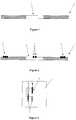
- FIG. 1A typical support layer is illustrated in figure 1 , with the reference 1.
- This layeris for example a 150 ⁇ m layer of PC as used in the field of RFID cards and applications.
- Other similar or equivalent layersmay of course also be used in the frame of the present invention.
- This layermay comprise a hole or opening 2 at the place where a chip will be deposited, as will be apparent from the following description.
- an antennais formed on the support layer 1.
- This antennais a wire antenna 3, and the two ends 4 of the wire antenna 3 pass over the opening 2 (when present in the layer) as illustrated in figures 2 and 3 (figure 3 only showing the ends passing over the hole 2 and not all the turns of the wire building the antenna, as is known in the art of RFID devices).
- Figure 4illustrates an optional method step in which a hot pre-press is applied to the support layer 1 with the wire 3 in order to fully embed the wire 3 in the support layer 1.
- This stepis accomplished with two heated plates 5 and 6 and has the result of entirely embedding the wire antenna 3 in the substrate forming the support layer 1.
- the purpose of this optional stepis double:
- Figure 5illustrates another optional step in the method of the invention, wherein the parts 4 of the wire which are used for the connection to the chip are flattened before the connection step.
- This systemuses at least one pressure plate 7 (preferably two) which press the parts 4 of the wire antenna 3 which are used for the connection to the chip contacts to flatten said parts 4.
- the result of this flattening operationis illustrated in figure 6 .
- the purpose of this optional stepare to reduce the thickness of the resulting inlay (as the one illustrated at the Figure 4 ), and also to obtain a larger and flat conductive surface to facilitate the connection to the chip pads.
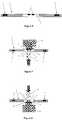
- FIGS 7 and 8illustrate the principle of the method of the invention for attaching a chip (or chip module) to the wire antenna applied to the support layer 1.
- a chipor chip module
- the antenna wire 3is transferred to a bonding station.
- the said support layer 1is approached on one side by a holding device 10 (such as a holding head) which holds a chip 11 whereby said chip comprises connection pads 12 and approached on the other side by a connection device 13.
- both the holding device and the connection deviceapply a reciprocal pressure to the wire 4 and the chip 11.
- the connectionis realized by thermo-compression or thermo-welding.
- the connection device 13may be made of a diamond head or another appropriate and equivalent head and material.
- the chip and the holding devicecan be brought from either side of the support layer 1.
- the support layer 1being vertical and the pressure axes of the devices 10 and 13 being horizontal.
- connection head 13is broad enough to cover the two pads 12 at the same time, the wires 4 may be connected simultaneously to the pads 12 of the chip 11. But a two step bonding sequence is also an affordable solution.
- a feature of the inventionis to have the welding made on the chip holding device, but with the two tools (connection device & holding device) positioned on the two side of the substrate carrying the wire.
- the key pointbeing that all elements have to be correctly aligned such that the two wire portions 4 can welded to the chip pads 12.
- wire positioning meanscould be mounted on either the holding device or the connection device in order to allow a fine adjustment of the wire portions position/orientation.
- the principle exposed in PCT application WO 2008/114091could be used here to properly position the wire parts 4 over the connection pads of the chip.
- any other wire gripping means or wire guiding means as known in the artare also applicable.
- connection device 13may be made of a diamond head or another appropriate and equivalent head and material.
- Figures 9 and 10illustrate the result of the connection operation as explained with reference to figure 7 and 8 .
- figure 9illustrates a functional inlay produced with the method of the present invention, in lateral cut-view and figure 10 illustrates the same result in a top view.
- the antenna wireis only schematically represented without all the wire turns that normally form the antenna, as is obvious for a person skilled in the art.
- the resulting inlayhas a thickness corresponding to the thickness of the chip plus the one of the ends portions 4 of the wire.
- the chip P60D144 VA of NXPshowing a total thickness (including bump thickness) of 87 ⁇ m, and the wire ends 4 being slightly flattened (from 80 ⁇ m to about 60 ⁇ m) during the compression bonding step, the deliverance of an approximately 150 ⁇ m thin RFID inlay can be expected. And even thinner inlays could be produced if the flattening step of Figure 5 is used.
- Figure 11illustrates an exemplary detail of a holding device 10 of the chip.
- the holding device 10uses vacuum to hold the chip 11, the said vacuum being applied through holes 15 opening in the top surface 16 of the holding device 10.
- the surface 16contains no aspiration holes in the zone 16' where the contacts 12 (or megabumps) of the chip 11 will be placed when the chip is held by the holding device to provide a stable support surface and a good welding.
- the holding deviceis made of metal or ceramic.
- the used of such vacuum holding systemis particularly recommended for very thin chip as the P60D144 VA of NXP as a mechanical pressure exerted on the chip edge is at risk (of breaking the chip).
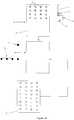
- Figure 12illustrates a top view of the system used to form the inlay according to the invention.
- Reference 18illustrates a feeder which is used to feed the system with individual chips 11 to be applied to the inlay.
- each chipmay be taken from the feeder 18 via a pick and place system 19 and deposited on the surface 16 of a holding device 10.
- the proper positioning and alignment of the chip 16 with the holding device 10can be achieved with the help of a camera vision control system.
- the holding device 10there is a sheet 20 forming the support layer which comprises several embedded antennas and a series of holes 2 as described hereabove (in the present case 4x8 holes) which correspond to the antennas applied to the support layer 1.
- the sheet 20may be cut later, after the embedding of the antennas and the application of the chips, into individual functional inlays as will be described hereunder.
- the number of individual inlays produced from a sheet 20can be varied considering the size of the sheet 20 and the size of an individual inlay 1.
- Figure 12illustrates a 8x4 configuration but of course other configurations are possible in the frame of the present invention.
- connection device 13is moved to the same position on the other side of the sheet 20 for cooperation with the holding device 10 and carrying out of the method steps of the invention.
- the connection devicemay also move in X, Y and Z directions to this effect.
- an adjustment systemis used to ensure a right alignment and possibly correct the relative position of the chip.
- the systemmay uses for example the X, Y positioning of the device 10 and 13 coupled for example to a vision system (camera) to this effect, the Z degree of freedom (vertical) being used to apply the reciprocal pressure between the holding device 10 and the connection device 13.
- connection device 13need only to be movable along the Z directions (to achieve the bonding pressure) and the holding device will have come to a fix position bonding position (defined in regards of the X-Y fixed connection device 13).
- Chips 11may be applied sequentially, one chip 11 after the other, or several chips 11 may be applied at the same time, for example line by line.
- the holding device 10 and connection device 13are adapted in consequence with a single head on each side (sequential application) or several heads (parallel application), the number and relative positions of the heads being of course adapted to the sheet 20 configuration and to the size of the chips 11.
- a parallel-working machineis illustrated in figure 13 as an example.
- oneuses an inline holding device system 10' with four heads 10 and a corresponding inline connection device system 13' with four connection heads 13.
- the inline systemmay for example comprise another number of heads, for example two or more, or even as much as the number of inlays to be produced from the sheet 20.
- Only one feeder 18is illustrated for placing a chip on each holding device via the pick and place system 19, but it is possible to use more than one such feeder 18, for example two or four to place a chip on each device 10 in parallel (four at a time) or in parallel and sequence (two and two). Of course, the choice may be varied according to circumstances and to the number of holding devices/heads.
- this position adjustmentmay be controlled just before the reciprocal pressure of the devices 10, 13 is applied to the chip 11 and wires 4.
- each device 10is controlled individually and adjusted if necessary so that the chips are correctly positioned before the pressure is applied.
- each head of the device 10is coupled to a measurement system, for example an optical system (camera) to allow the said adjustment to take place.
- each antenna position on the sheet 20 or of each opening 2for example via optical means (i.e. a camera) and once these positions are known, place the chips 11 at a corresponding position on the holding devices 10.
- optical meansi.e. a camera
- This constructioncould be used if the heads of the holding device 10 are fixed relatively to each other, a position adjustment being made at the level of the individual chip 11 on the heads.
- the holding devicecan also be made of one elongate vacuum plate, as the one of Figure 11 but much larger and with the possibility to place the chips at convenience (no fixed positions).
- the relative position adjustmentmay be made between each head of the device 10 (and 13) once the chips are held by the holding heads but before the reciprocal pressure is applied in accordance with the method of the present invention.
- Figure 14illustrate a further embodiment of a simultaneous parallel application of chips in a bonding station. More specifically, reference 21 identifies a chip 11 placement area or station on which a pick and place tool 22 position individual chips taken from a feeder 18. The position of each chip could be determined previously from the sheet 20 which carries the embedded antennas 3 and may also contain the holes 2. This determination could be made for example by way of optical means (camera for example). Once the positions of the antennas are known, it is possible via the pick and place tool 22 to deposit each chip 11 at a corresponding position in the chip placement area 21, on a rigid vacuum plate 23 for example made of metal or ceramic. In this embodiment, the support 23 plays the role of the holding device 10 described previously, but this holding device carries here a plurality of chips 11.
- the plate 23in then moved along a processing path to a bonding area or station 24 to which a sheet 20 with the antennas is brought is also processed for application and connection of the chips 11 to the antennas 4 according to the principle of the present invention as described herein.
- Each chip 11may be individually sequentially bonded to the antenna 4 by using a connection device 13 (see the principle exposed in relation to figures 7 and 8 ) or it is possible to have a parallel procedure where plurality (i.e. more than one) chip is connected to an antenna. In such case, there are also a plurality of connection heads (reference 13' in figure 14 ) working in parallel.
- connection headsmay be equal to the number of chips to be placed on one sheet 20, such that the connection of the chips to the antennas may be made in one single process step.
- the sheet 20is then transported to another area or station for further treatment, for example for the cutting of individual functional inlays.
- the entire systemis preferably monitored by a computer system and appropriate programs that are able to carry out the method.
- Such computer means and programswill manage and run the method steps, at least for example the feeding of sheets 19 and chips 11, the chip placement on the holding heads 10 with control of the vacuum, the moving of the heads at the right position on the sheets, the adjustment of the positioning (via dedicated means such as cameras) of the chips 11 and the connection step per se with the reciprocal pressure being applied and the further processing steps of the inlays produced by the method, for example moving in a cutting station where the individual inlays are produced by cutting the sheet 20 into such individual inlays.
Landscapes
- Engineering & Computer Science (AREA)
- Microelectronics & Electronic Packaging (AREA)
- Computer Hardware Design (AREA)
- Physics & Mathematics (AREA)
- General Physics & Mathematics (AREA)
- Power Engineering (AREA)
- Theoretical Computer Science (AREA)
- Manufacturing & Machinery (AREA)
- Condensed Matter Physics & Semiconductors (AREA)
- Computer Networks & Wireless Communication (AREA)
- Details Of Aerials (AREA)
Description
- The present invention concerns the field of RFID devices comprising an antenna connected to a chip via direct bonding.
- More specifically, the present invention concerns a method for direct bonding of a chip to a wire antenna which is embedded in a substrate to form a functional inlay.
- The present invention also concerns a functional inlay produced with the method described herein.
US patent 6,233,818 to Finn et al. discloses a method of manufacturing of a RFID inlay. More specifically, this patent discloses a process and device for the contacting of a wire conductor in the course of the manufacture of a transponder unit arranged on a substrate and comprising a wire coil and a chip unit such as a chip module with terminal areas. By virtue of the process according to the invention described in this prior art, there is no longer any necessity, with a view to bringing the terminal areas of the chip unit into contact with the ends of the coil, to provide a separate contact substrate on which enlarged terminal areas are formed. Rather, the coil substrate, which is used as substrate for the wire coil and which, for example in the case where the transponder unit is intended to serve for the manufacture of a chip card, is formed by means of a plastic support sheet corresponding to the dimensions of the chip card, serves as a contacting or positioning aid for the relative positioning of the ends of the coil in relation to the terminal areas of the chip unit. In this case the chip unit may either be arranged in a recess in the substrate provided for this purpose or may be provided on the surface of the substrate. The first alternative affords the possibility of arranging the chip unit in the recess optionally prior to fixation of the wire conductors or of introducing the chip unit into the recess only after fixation of the wire conductors, in order subsequently to implement the actual contacting of the wire conductors on the terminal areas.- More specifically, in this prior art, firstly an antenna is applied to the substrate via a wiring device using ultrasound to attach the wire to the substrate. An antenna is thereby formed with an initial antenna region and a final antenna region, both regions traversing a window shaped substrate recess. Then, a chip module is placed in the recess whereby terminal contact areas of the module abut the initial and terminal antenna regions. Subsequently, an electrical connection is realized between the terminal contact areas and the initial and final antenna regions of the antenna by means of a thermode which under the influence of pressure and temperature creates a connection by material closure between the wire antenna and the terminal contact areas of the chip (this is also called thermo compression).
EP patent application 2 001 077- The inventions disclosed in the documents cited above relate all in fact (in the practice) to the use of chip modules. Per definition, chip modules are much larger than chips and also comprise much larger connection pads. A typical chip module for contactless inlay is the mob6 from NXP, presenting a surface area of 8100 x 5100 µm for a thickness of 300 µm, with connection pads having a surface area of 1500 x 5100 µm each.
US patent 5,572,410 discloses a chip being directly connected to wire antenna. In this patent, a wire is wound around a core and the two ends of the wire are soldered to metal paths deposited over the active layer of the chip. This technology, which is called "direct bonding", minimizes the size of the resulting transponder, the number of its constituting elements as the related production costs.- The metal paths which are extensions of the usual small pads of the chips, are called megabumps (or megapads) and show a dimension adapted to the connection of the antenna wire (which shows typically a diameter of 60-80 µm). For example, a typical chip used for such appllications is the Hitag µ from NXP, wherein the chip surface area is of 550 x 550 µm for 150 µm thickness and the megabump show a surface area of 294 x 164 µm (while the original pads are only 60 x 60 µm).
- It also has to be noted that in the particular application disclosed in this document, the antenna is not embedded in a support layer, but wound around a ferrite core. The resulting transponder has a resonant frequency of about 125 kHz and the antenna show over 300 turns. This does not require a fine tuning of antenna, and the antenna spires are just wound one on the other at high speed.
- However, if one wants to work at higher frequency, as for example 13.56 MHz, one will have to control the form and the relative spacing of each spire in order to tune the antenna correctly. Wire embedding is the most efficient and popular technology for manufacturing of high frequency wire antennas. But up to now, this was made exclusively by using chip modules. This introduces an important limitation as the resulting inlay cannot be thinner than the used module.
- The manufacturing of thinner high frequency inlays is the main motivation to to try combine direct bonding and wire embedding technologies.
- Table 1 propose a list of some of the high frequency chips on the nmarket which could be used for direct bonding. These chips present much smaller dimensions (not only in thickness) in comparison to the mob6 from NXP described above.
Table 1: examples of high frequency chips applicable for direct bonding Supplier Ref. Chip dims [µm] Chip thickness [µm] Bumps dims [µm] Bump thickness [µm] Total thickness [µm] EM EM4233 1034x1054 100,200 or 280 300x400 18 N/A NXP MF CLASSIC 1k 650X675 150 164x294 18 168 INSIDE Picopass 2k V1.2 1198x1192 280 310x712 20 300 NXP P60D080/P60D144 VA 2166X3004 75 600X600 12 87 INSIDE AT90SC28880RCFV 2740X2970 75 600x680 12 87 - The problem is to handle such small chips properly when in the same time the antenna wire is fixed on a huge sheet of plastic. Solutions used today for chip modules (which are much heavier and larger than single chips) are no more usable at such large manufacturing scale.
US2009213027 discloses an antenna wire mounted to a substrate so that end portions of the wire are spaced far enough apart for a transponder chip to be positioned there between, such as into a recess in the substrate. The end portions are left unmounted, as "wire bridges", "jump loops", or "flat loops". The end portions may be re-positioned to be over the terminals of the chip for bonding. Or, the chip (or substrate) may be moved (such as side-to-side, or rotated) so that the chip's terminals are under the end portions of the wire for bonding. Insulation may be removed from the end portions of the wire prior to bonding.US2009061561 discloses a method of producing an electronic apparatus that is inexpensive, contributes to high productivity, and can achieve good communication characteristics. A method of producing an electronic apparatus composed of an IC chip having an external electrode formed on each of a set of opposing surfaces of the IC chip; an antenna circuit having a slit formed in it; and a short circuit plate for electrically connecting the IC chip and the antenna circuit. In the method, a disc-like conveyor has hands on its outer periphery, and each hand is capable of holding a single IC chip. The hands hold IC chips individually, and the IC chips are conveyed by rotation of the disc-like conveyor. As a result, a plurality of IC chips whose maximum number is equal to the number of the hands can be simultaneously conveyed.- An aim of the present invention is to improve the methods.
- More precisely, an aim of the present invention is to manufacture the thinner RFID inlay possible by direct bonding of a chip, such as a RFID chip, to an wire antenna that is embedded in a substrate.
- In summary the invention allows getting a high frequency RFID monolayer thinner than the sum of the thickness of the chip plus the thickness of the antenna (chip and antenna being inside the carrier monolayer itself).
- Other HF RFID technologies known in the art and using a naked chip as flip chip technology will be thicker due to the fact they need a carrier layer without holes where the antenna (etched antenna or screen printed antenna) will be put on. After this step, a chip is connected on the antenna and the final thickness will be the addition of the chip thickness + antenna thickness+ carrier layer thickness. In this case, a carrier layer has to be added to the total thickness of the layer, a disadvantage that is not present anymore when using the principle of the invention as described in the present application.
- According to one aspect, the invention is directed to a method of direct bonding an embedded wire antenna to a chip whereby the tooling allows at the same time to hold the chip from one side and to connect the antenna wires to said chip through a connection head, such as a welding head, from the other side.
- More precisely, the method comprises the steps of
claim 1. - In an embodiment of the method, the connection step may be achieved by thermo compression.
- In an embodiment of the method, connection portions of the wire antennas dedicated to be connected to the connection pads of the chip are positioned over the through hole(s).
- In an embodiment of the method, the connection portions of the wire antenna are positioned over the through hole(s) during the during the wire antenna embedding step.
- In an embodiment, the method may comprise an additional step to reposition the connection portions of the wire antenna(s) over the through hole(s) after the wire embedding step and before or during the connection step with a chip.
- In an embodiment of the method, the connection portions undergo a flattening step before the connection step to a chip to provide a larger and substantially flat conductive area for connection to the contact pads of the chip.
- In an embodiment of the method, the holding device and/or the connection device comprise means to position and maintain the connection portions aligned with connection pads during the connection step.
- In an embodiment of the method, the embedding step comprises a hot press step to completely embed the wire inside the support layer.
- In an embodiment of the method, the holding device maintains the chip in place by vacuum.
- In an embodiment of the method, all the connection pads of a chip are connected to the wire antenna simultaneously.
- In an embodiment of the method, the simultaneous connections are achieved by one single compression head which is broad enough to cover all connection pads of the chip.
- In an embodiment of the method, a plurality of functional inlays are manufactured simultaneously, as the support layer is a large format comprising a plurality of positions for a plurality of embedded antenna wires to be connected to a plurality of chips.
- In an embodiment of the method, the holding device comprises a plurality of positions to hold a plurality of the chips to be connected to a plurality of the antennas.
- In an embodiment of the method, the holding device is formed by a vacuum plate comprising multiple sucking holes so that the multiple chips are maintained in position by vacuum. The vacuum plate is being movable at least in a direction perpendicular to the processing path of the support layer.
- In an embodiment of the method, the connection device comprises a plurality of connection heads to connect simultaneously a plurality of the chips to a plurality of the antennas.
- The present invention will be better understood from the following detailed description and of the following drawings which show
Figure 1 illustrates a side cut-view of a support layer that is used in the present invention;Figure 2 illustrates the support layer offigure 1 on which a wire (typically a wire antenna) has been embedded;Figure 3 schematically illustrates a top view of the support layer offigure 2 ;Figure 4 illustrates an optional schematical view of the wire embedding of the support layer offigure 2 ;Figure 5 illustrates an optional schematical view of a wire flattening step;Figure 6 illustrates schematically the result of the flattening step offigure 5 ;Figures 7 and 8 illustrate the deposition of a chip according to the present invention in two variants;Figure 9 illustrate the result of the deposition step offigures 7 or 8 ;Figure 10 illustrates a top view offigure 9 ;Figure 11 illustrate an embodiment of a holding head according to the present invention;Figure 12 illustrates a schematical view of an embodiment of a system for carrying out the method of the present invention;Figure 13 illustrates a schematical view of another embodiment of a system for carrying out the method of the present invention;Figure 14 illustrates a schematical view of another embodiment of a system for carrying out the method of the present invention;Figure 15 illustrates a side view showing how to handle an embodiment of the invention.- A typical support layer is illustrated in
figure 1 , with thereference 1. This layer is for example a 150µm layer of PC as used in the field of RFID cards and applications. Other similar or equivalent layers (with other sizes and/or made of other materials) may of course also be used in the frame of the present invention. - This layer may comprise a hole or
opening 2 at the place where a chip will be deposited, as will be apparent from the following description. - In order to build a functional inlay, firstly an antenna is formed on the
support layer 1. This antenna is awire antenna 3, and the two ends 4 of thewire antenna 3 pass over the opening 2 (when present in the layer) as illustrated infigures 2 and 3 (figure 3 only showing the ends passing over thehole 2 and not all the turns of the wire building the antenna, as is known in the art of RFID devices). Figure 4 illustrates an optional method step in which a hot pre-press is applied to thesupport layer 1 with thewire 3 in order to fully embed thewire 3 in thesupport layer 1. This step is accomplished with twoheated plates 5 and 6 and has the result of entirely embedding thewire antenna 3 in the substrate forming thesupport layer 1. The purpose of this optional step is double:- 1. achieve a final functional inlay as thin as possible. The ideal theoretical thickness corresponding to the thickness of the chip plus the one of the
ends portions 4 of the wire (see alsoFigure 9 for the final result). - 2. be sure to get the complete antenna at the same level inside the support layer (included the two end of the antenna) in order to facilitate the further steps if needed.
Figure 5 illustrates another optional step in the method of the invention, wherein theparts 4 of the wire which are used for the connection to the chip are flattened before the connection step. This system uses at least one pressure plate 7 (preferably two) which press theparts 4 of thewire antenna 3 which are used for the connection to the chip contacts to flatten saidparts 4. The result of this flattening operation is illustrated infigure 6 . The purpose of this optional step are to reduce the thickness of the resulting inlay (as the one illustrated at theFigure 4 ), and also to obtain a larger and flat conductive surface to facilitate the connection to the chip pads.Figures 7 and 8 illustrate the principle of the method of the invention for attaching a chip (or chip module) to the wire antenna applied to thesupport layer 1. Once theantenna wire 3 has been applied to the support layer 1 (see above description), it is transferred to a bonding station. There, the saidsupport layer 1 is approached on one side by a holding device 10 (such as a holding head) which holds achip 11 whereby said chip comprisesconnection pads 12 and approached on the other side by aconnection device 13. In order to effect the connection between theconnection pads 12 and theparts 4 of the wire used for connection, both the holding device and the connection device apply a reciprocal pressure to thewire 4 and thechip 11. Typically, the connection is realized by thermo-compression or thermo-welding. As an example, theconnection device 13 may be made of a diamond head or another appropriate and equivalent head and material.- As is illustrated, the chip and the holding device can be brought from either side of the
support layer 1. By any other configuration is possible, for example thesupport layer 1 being vertical and the pressure axes of thedevices - Advantageously, if the
connection head 13 is broad enough to cover the twopads 12 at the same time, thewires 4 may be connected simultaneously to thepads 12 of thechip 11. But a two step bonding sequence is also an affordable solution. - A feature of the invention is to have the welding made on the chip holding device, but with the two tools (connection device & holding device) positioned on the two side of the substrate carrying the wire. The key point being that all elements have to be correctly aligned such that the two
wire portions 4 can welded to thechip pads 12. - Optionally, wire positioning means could be mounted on either the holding device or the connection device in order to allow a fine adjustment of the wire portions position/orientation. For example, the principle exposed in
PCT application WO 2008/114091 could be used here to properly position thewire parts 4 over the connection pads of the chip. Naturally, any other wire gripping means or wire guiding means as known in the art are also applicable. - As an example, the
connection device 13 may be made of a diamond head or another appropriate and equivalent head and material. Figures 9 and 10 illustrate the result of the connection operation as explained with reference tofigure 7 and 8 . Specifically,figure 9 illustrates a functional inlay produced with the method of the present invention, in lateral cut-view andfigure 10 illustrates the same result in a top view. In this figure, for the sake of simplicity, the antenna wire is only schematically represented without all the wire turns that normally form the antenna, as is obvious for a person skilled in the art.- As discussed above (see the description of
Figure 4 ), the resulting inlay has a thickness corresponding to the thickness of the chip plus the one of theends portions 4 of the wire. For example, the chip P60D144 VA of NXP showing a total thickness (including bump thickness) of 87 µm, and the wire ends 4 being slightly flattened (from 80 µm to about 60 µm) during the compression bonding step, the deliverance of an approximately 150 µm thin RFID inlay can be expected. And even thinner inlays could be produced if the flattening step ofFigure 5 is used. Figure 11 illustrates an exemplary detail of a holdingdevice 10 of the chip. In this example, the holdingdevice 10 uses vacuum to hold thechip 11, the said vacuum being applied throughholes 15 opening in thetop surface 16 of the holdingdevice 10. Preferably, thesurface 16 contains no aspiration holes in the zone 16' where the contacts 12 (or megabumps) of thechip 11 will be placed when the chip is held by the holding device to provide a stable support surface and a good welding.- Typically, the holding device is made of metal or ceramic. The used of such vacuum holding system is particularly recommended for very thin chip as the P60D144 VA of NXP as a mechanical pressure exerted on the chip edge is at risk (of breaking the chip).
Figure 12 illustrates a top view of the system used to form the inlay according to the invention.Reference 18 illustrates a feeder which is used to feed the system withindividual chips 11 to be applied to the inlay. For example, each chip may be taken from thefeeder 18 via a pick andplace system 19 and deposited on thesurface 16 of a holdingdevice 10. Preferably, the proper positioning and alignment of thechip 16 with the holdingdevice 10 can be achieved with the help of a camera vision control system. Next to the holdingdevice 10, there is asheet 20 forming the support layer which comprises several embedded antennas and a series ofholes 2 as described hereabove (in the present case 4x8 holes) which correspond to the antennas applied to thesupport layer 1.- The
sheet 20 may be cut later, after the embedding of the antennas and the application of the chips, into individual functional inlays as will be described hereunder. The number of individual inlays produced from asheet 20 can be varied considering the size of thesheet 20 and the size of anindividual inlay 1.Figure 12 illustrates a 8x4 configuration but of course other configurations are possible in the frame of the present invention. - Once a
chip 11 has been picked and placed on a holdingdevice 10, said device may be moved in X, Y and Z directions (Z being perpendicular to the X,Y axis illustrated infigure 12 ), to the right position on thesheet 20 for placing thechip 12 as illustrated infigures 7 and 8 and discussed above. At the same time, theconnection device 13 is moved to the same position on the other side of thesheet 20 for cooperation with the holdingdevice 10 and carrying out of the method steps of the invention. The connection device may also move in X, Y and Z directions to this effect. - When a
chip 11 is being connected to anantenna 3, it is important to ensure that thechip 11 is properly positioned and that thepads 12 are at the right position with respect to thewire portion 4 of the antenna that are used for the connection. - To this effect, an adjustment system is used to ensure a right alignment and possibly correct the relative position of the chip. The system may uses for example the X, Y positioning of the
device device 10 and theconnection device 13. - Alternatively, the positioning of the
sheet 20 can also be controlled in the X-Y plane. In such a configuration, theconnection device 13 need only to be movable along the Z directions (to achieve the bonding pressure) and the holding device will have come to a fix position bonding position (defined in regards of the X-Y fixed connection device 13). Chips 11 may be applied sequentially, onechip 11 after the other, orseveral chips 11 may be applied at the same time, for example line by line. The holdingdevice 10 andconnection device 13 are adapted in consequence with a single head on each side (sequential application) or several heads (parallel application), the number and relative positions of the heads being of course adapted to thesheet 20 configuration and to the size of thechips 11.- A parallel-working machine is illustrated in
figure 13 as an example. In this example, one uses an inline holding device system 10' with fourheads 10 and a corresponding inline connection device system 13' with four connection heads 13. This is only an example and the inline system may for example comprise another number of heads, for example two or more, or even as much as the number of inlays to be produced from thesheet 20. - Only one
feeder 18 is illustrated for placing a chip on each holding device via the pick andplace system 19, but it is possible to use more than onesuch feeder 18, for example two or four to place a chip on eachdevice 10 in parallel (four at a time) or in parallel and sequence (two and two). Of course, the choice may be varied according to circumstances and to the number of holding devices/heads. - In one embodiment, when the
chips 11 are applied individually, this position adjustment may be controlled just before the reciprocal pressure of thedevices chip 11 andwires 4. - In another embodiment, in case of parallel application of
chips 11, the adjustment may be made at the same moment, but eachdevice 10 is controlled individually and adjusted if necessary so that the chips are correctly positioned before the pressure is applied. Preferably, in such configuration, each head of thedevice 10 is coupled to a measurement system, for example an optical system (camera) to allow the said adjustment to take place. - In a further embodiment, especially useful when
several chips 11 are applied in parallel, one may firstly determine each antenna position on thesheet 20 or of each opening 2 (if present) for example via optical means (i.e. a camera) and once these positions are known, place thechips 11 at a corresponding position on the holdingdevices 10. This construction could be used if the heads of the holdingdevice 10 are fixed relatively to each other, a position adjustment being made at the level of theindividual chip 11 on the heads. The holding device can also be made of one elongate vacuum plate, as the one ofFigure 11 but much larger and with the possibility to place the chips at convenience (no fixed positions). Alternatively, the relative position adjustment may be made between each head of the device 10 (and 13) once the chips are held by the holding heads but before the reciprocal pressure is applied in accordance with the method of the present invention. Figure 14 illustrate a further embodiment of a simultaneous parallel application of chips in a bonding station. More specifically,reference 21 identifies achip 11 placement area or station on which a pick andplace tool 22 position individual chips taken from afeeder 18. The position of each chip could be determined previously from thesheet 20 which carries the embeddedantennas 3 and may also contain theholes 2. This determination could be made for example by way of optical means (camera for example). Once the positions of the antennas are known, it is possible via the pick andplace tool 22 to deposit eachchip 11 at a corresponding position in thechip placement area 21, on arigid vacuum plate 23 for example made of metal or ceramic. In this embodiment, thesupport 23 plays the role of the holdingdevice 10 described previously, but this holding device carries here a plurality ofchips 11.- Once the desired number of
chips 11 has been placed on theplate 23, theplate 23 in then moved along a processing path to a bonding area orstation 24 to which asheet 20 with the antennas is brought is also processed for application and connection of thechips 11 to theantennas 4 according to the principle of the present invention as described herein. - Each
chip 11 may be individually sequentially bonded to theantenna 4 by using a connection device 13 (see the principle exposed in relation tofigures 7 and 8 ) or it is possible to have a parallel procedure where plurality (i.e. more than one) chip is connected to an antenna. In such case, there are also a plurality of connection heads (reference 13' infigure 14 ) working in parallel. - The number of connection heads may be equal to the number of chips to be placed on one
sheet 20, such that the connection of the chips to the antennas may be made in one single process step. - Note that an issue to the application of such a
large holding plate 23 is that support bars 25 as shown inFigure 15 are needed in order to maintain thesupport sheet 20 horizontal. A possible solution is to creategrooves 26 corresponding to the support bars in theplate 24, such that when the holding plate is approached near of thesupport sheet 20, the support bars will enter in thegrooves 26 without blocking the movement of theplate 23. - Once the chips are connected to the antennas, the
sheet 20 is then transported to another area or station for further treatment, for example for the cutting of individual functional inlays. - The entire system is preferably monitored by a computer system and appropriate programs that are able to carry out the method. Typically, such computer means and programs will manage and run the method steps, at least for example the feeding of
sheets 19 andchips 11, the chip placement on the holding heads 10 with control of the vacuum, the moving of the heads at the right position on the sheets, the adjustment of the positioning (via dedicated means such as cameras) of thechips 11 and the connection step per se with the reciprocal pressure being applied and the further processing steps of the inlays produced by the method, for example moving in a cutting station where the individual inlays are produced by cutting thesheet 20 into such individual inlays.
Claims (15)
- A method of manufacturing a functional inlay, the method comprising:- providing a support layer (1) with at least a first and a second side;- embedding a wire antenna (3) in said support layer (1) comprising a through hole (2);- processing said support layer (1) with said embedded wire antenna (3) to a connection station along a processing path, in which:wherein the chip (11) is positioned by the holding device (10) in the through hole (2) during or shortly before the connection step.- said support layer (1) is approached on said first side by a holding device (10) moving essentially perpendicular to the processing path and holding a chip (11) with a surface comprising connection pads (12);- said support layer (1) is approached on said second side by a connection device (13) moving essentially perpendicular to the processing path; and- said antenna wire (3) is connected to said connection pads (12) by means of a reciprocal pressure exerted between said holding device (10) and said connection device (13);
- The method as defined in claim 1, wherein the connection step is achieved by thermo compression.
- The method as defined in claim 1, wherein connection portions (4) of the wire antennas dedicated to be connected to the connection pads (12) of the chip (11) are positioned over said through hole (2).
- The method as defined in claim 3, wherein the connection portions (4) of the wire antenna (3) are positioned over the said through hole (2) during the wire antenna embedding step.
- The method as defined in claim 3 comprising an additional step to reposition the connection portions (4) of the wire antenna (3) over the said through hole (2) after the wire embedding step and before or during the connection step with the chip (11).
- The method as defined in one of the claims 3 to 5, wherein the connection portions (4) undergo a flattening step before the connection step to the chip (11) to provide a larger and substantially flat conductive area for connection to the contacts of the chip (11).
- The method as defined in one of claims 3 to 6, wherein the holding device and/or the connection device (13) comprise means to position and maintain the connection portions (4) aligned with connection pads (12) during the connection step.
- The method as defined in one of the preceding claims, wherein the embedding step comprises a hot press step to completely embed the wire inside the support layer (1).
- The method as defined in one of the preceding claims, wherein the holding device (10) is maintaining the chip (11) in place by vacuum.
- The method as defined in one of the preceding claims, wherein all the connection pads (12) of the chip are connected to the wire antenna (3) simultaneously.
- The method as defined in claim 10, wherein said simultaneous connections are achieved by one single compression head which is broad enough to cover all connection pads (12) of the chip.
- The method as defined in one of the preceding claims, wherein a plurality of functional inlays are manufactured simultaneously, as the support layer (1) is a large format comprising a plurality of positions for a plurality of embedded antenna wires to be connected to a plurality of chips (11).
- The method as defined in claim 12, wherein the holding device (10) comprises a plurality of positions to hold a plurality of the chips to be connected to a plurality of the antennas.
- The method as defined in claim 13, wherein the holding device (10) is formed by a vacuum plate comprising multiple sucking holes so that the multiple chips are maintained in position by vacuum.
- The method as defined in one of claims 12 to 14, wherein the connection device (13) comprises a plurality of connection heads to connect simultaneously a plurality of the chips to a plurality of the antennas.
Applications Claiming Priority (1)
| Application Number | Priority Date | Filing Date | Title |
|---|---|---|---|
| PCT/EP2012/063671WO2014008937A1 (en) | 2012-07-12 | 2012-07-12 | Method of manufacturing a functional inlay |
Publications (2)
| Publication Number | Publication Date |
|---|---|
| EP2873031A1 EP2873031A1 (en) | 2015-05-20 |
| EP2873031B1true EP2873031B1 (en) | 2018-08-22 |
Family
ID=46640649
Family Applications (1)
| Application Number | Title | Priority Date | Filing Date |
|---|---|---|---|
| EP12745650.7AActiveEP2873031B1 (en) | 2012-07-12 | 2012-07-12 | Method of manufacturing a functional inlay |
Country Status (5)
| Country | Link |
|---|---|
| US (2) | US9501733B2 (en) |
| EP (1) | EP2873031B1 (en) |
| CN (1) | CN104471593B (en) |
| MY (1) | MY189207A (en) |
| WO (1) | WO2014008937A1 (en) |
Families Citing this family (11)
| Publication number | Priority date | Publication date | Assignee | Title |
|---|---|---|---|---|
| US10262906B2 (en) | 2014-12-15 | 2019-04-16 | Assa Abloy Ab | Method of producing a functional inlay and inlay produced by the method |
| WO2017079847A1 (en)* | 2015-11-11 | 2017-05-18 | Ks Circuits Inc. | Communications antennas, systems and methods of manufacture thereof |
| US20180091070A1 (en)* | 2016-09-23 | 2018-03-29 | Hamilton Sundstrand Corporation | Redundant channel motor and method |
| US10702198B2 (en)* | 2016-11-29 | 2020-07-07 | Dexcom, Inc. | Wire-assembly apparatus for invasive biosensors |
| CN111279361B (en) | 2017-09-29 | 2023-08-04 | 艾利丹尼森零售信息服务公司 | Systems and methods for transferring flexible conductors to a moving web |
| WO2019068068A1 (en)* | 2017-09-29 | 2019-04-04 | Avery Dennison Retail Information Services, Llc | Strap mounting techniques for wire format antennas |
| KR102001243B1 (en)* | 2017-11-28 | 2019-07-17 | 신혜중 | Embedding head for forming an antenna wire |
| WO2019236476A1 (en) | 2018-06-04 | 2019-12-12 | SparkMeter, Inc. | Wireless mesh data network with increased transmission capacity |
| US10833051B2 (en)* | 2019-01-24 | 2020-11-10 | International Business Machines Corporation | Precision alignment of multi-chip high density interconnects |
| EP4022511B1 (en) | 2019-08-28 | 2023-07-26 | Avery Dennison Retail Information Services LLC | Rotation-insensitive rfid devices and methods of forming the same |
| SE2051294A1 (en) | 2020-11-06 | 2022-05-07 | Fingerprint Cards Anacatum Ip Ab | Integrated biometric sensor module and method for manufacturing a smartcard comprising an integrated biometric sensor module |
Family Cites Families (19)
| Publication number | Priority date | Publication date | Assignee | Title |
|---|---|---|---|---|
| US6097089A (en)* | 1998-01-28 | 2000-08-01 | Mitsubishi Gas Chemical Company, Inc. | Semiconductor plastic package, metal plate for said package, and method of producing copper-clad board for said package |
| JPS6384130A (en)* | 1986-09-29 | 1988-04-14 | Toshiba Corp | Wire bonding |
| AU655455B2 (en) | 1991-02-25 | 1994-12-22 | Assa Abloy Ab | Method for fixing a winding to an electronic circuit |
| US5994910A (en)* | 1994-12-21 | 1999-11-30 | International Business Machines Corporation | Apparatus, and corresponding method, for stress testing wire bond-type semi-conductor chips |
| US6242802B1 (en)* | 1995-07-17 | 2001-06-05 | Motorola, Inc. | Moisture enhanced ball grid array package |
| CA2245775C (en) | 1996-02-12 | 2004-04-06 | David Finn | Method and device for bonding a wire conductor |
| US5731244A (en)* | 1996-05-28 | 1998-03-24 | Micron Technology, Inc. | Laser wire bonding for wire embedded dielectrics to integrated circuits |
| JP3065549B2 (en)* | 1997-01-09 | 2000-07-17 | 富士通株式会社 | Semiconductor chip component mounting method |
| TW497236B (en)* | 2001-08-27 | 2002-08-01 | Chipmos Technologies Inc | A soc packaging process |
| US7176506B2 (en)* | 2001-08-28 | 2007-02-13 | Tessera, Inc. | High frequency chip packages with connecting elements |
| JP4697228B2 (en)* | 2005-04-18 | 2011-06-08 | 日立化成工業株式会社 | Manufacturing method of electronic device |
| US20070018186A1 (en)* | 2005-07-19 | 2007-01-25 | Lg Chem, Ltd. | Light emitting diode device having advanced light extraction efficiency and preparation method thereof |
| US8067253B2 (en)* | 2005-12-21 | 2011-11-29 | Avery Dennison Corporation | Electrical device and method of manufacturing electrical devices using film embossing techniques to embed integrated circuits into film |
| US20080179404A1 (en) | 2006-09-26 | 2008-07-31 | Advanced Microelectronic And Automation Technology Ltd. | Methods and apparatuses to produce inlays with transponders |
| US7979975B2 (en)* | 2007-04-10 | 2011-07-19 | Feinics Amatech Teavanta | Methods of connecting an antenna to a transponder chip |
| KR101346050B1 (en) | 2006-09-26 | 2013-12-31 | 에이치아이디 글로벌 게엠베하 | Method of connecting an antenna to a transponder chip and corresponding inlay substrate |
| JP2008177350A (en)* | 2007-01-18 | 2008-07-31 | Fujitsu Ltd | Electronic device manufacturing method and manufacturing apparatus |
| US20080191333A1 (en)* | 2007-02-08 | 2008-08-14 | Advanced Chip Engineering Technology Inc. | Image sensor package with die receiving opening and method of the same |
| EP2001077A1 (en)* | 2007-05-21 | 2008-12-10 | Gemplus | Method of manufacturing a device comprising a transponder antenna connected to connecting pads and device obtained |
- 2012
- 2012-07-12EPEP12745650.7Apatent/EP2873031B1/enactiveActive
- 2012-07-12CNCN201280074655.2Apatent/CN104471593B/enactiveActive
- 2012-07-12USUS14/413,801patent/US9501733B2/enactiveActive
- 2012-07-12MYMYPI2015000035Apatent/MY189207A/enunknown
- 2012-07-12WOPCT/EP2012/063671patent/WO2014008937A1/enactiveApplication Filing
- 2016
- 2016-09-19USUS15/269,464patent/US9780062B2/enactiveActive
Non-Patent Citations (1)
| Title |
|---|
| None* |
Also Published As
| Publication number | Publication date |
|---|---|
| MY189207A (en) | 2022-01-31 |
| US20160026910A1 (en) | 2016-01-28 |
| CN104471593A (en) | 2015-03-25 |
| US9501733B2 (en) | 2016-11-22 |
| CN104471593B (en) | 2018-02-02 |
| WO2014008937A1 (en) | 2014-01-16 |
| US9780062B2 (en) | 2017-10-03 |
| US20170005066A1 (en) | 2017-01-05 |
| EP2873031A1 (en) | 2015-05-20 |
Similar Documents
| Publication | Publication Date | Title |
|---|---|---|
| EP2873031B1 (en) | Method of manufacturing a functional inlay | |
| EP2577570B1 (en) | Mounting and connecting an antenna wire in a transponder | |
| US9027227B2 (en) | Transferring an antenna to an RFID inlay substrate | |
| EP2147401B2 (en) | Dual interface inlays | |
| CN101627400B (en) | Method for connecting an antenna to a transponder chip and corresponding inlay substrate | |
| JP5408720B2 (en) | Method for connecting antenna to transponder chip and corresponding inlay substrate | |
| US20080150817A1 (en) | Method and Apparatus for Making A Radio Frequency Inlay | |
| WO2012061964A1 (en) | Smart dual-interface card and welding packaging process thereof | |
| US10713552B2 (en) | RFID tag manufacturing method, RFID tag manufacturing device, and transfer sheet manufacturing method | |
| US10474308B2 (en) | Position detection sensor and method for manufacturing position detection sensor | |
| JP4386023B2 (en) | IC mounting module manufacturing method and manufacturing apparatus | |
| KR101006873B1 (en) | How to inlay and laminate integrated circuit chip and antenna coil on board | |
| US10262906B2 (en) | Method of producing a functional inlay and inlay produced by the method | |
| JP2014096125A (en) | Method of manufacturing non-contact communication medium, non-contact communication medium, and method of connecting antenna and circuit device | |
| JP5886174B2 (en) | Non-contact communication medium manufacturing method, non-contact communication medium, and antenna and circuit device connection method | |
| JP2015228234A (en) | Manufacturing method of non-contact communication medium, and connection method of antenna and circuit device | |
| JP2008084149A (en) | Non-contact communication member manufacturing method, non-contact communication member manufacturing apparatus, interposer manufacturing method, interposer manufacturing apparatus, and IC chip holding apparatus | |
| AU2007358536B2 (en) | Method of connecting an antenna to a transponder chip and corresponding inlay substrate | |
| JP2003069294A (en) | IC chip mounting device | |
| JP5989198B2 (en) | Method for manufacturing non-contact communication medium, and method for connecting antenna and circuit device | |
| CN101971195B (en) | Method of manufacturing a device comprising a radio frequency transponder antenna formed on a support with two end portions and the resulting device | |
| SG174832A1 (en) | Method and apparatus for making a radio frequency inlay | |
| JP2005182390A (en) | Non-contact type IC card inlet manufacturing method and manufacturing apparatus | |
| JP2004087533A (en) | Process for producing semiconductor device and bonder for use therein |
Legal Events
| Date | Code | Title | Description |
|---|---|---|---|
| PUAI | Public reference made under article 153(3) epc to a published international application that has entered the european phase | Free format text:ORIGINAL CODE: 0009012 | |
| 17P | Request for examination filed | Effective date:20150211 | |
| AK | Designated contracting states | Kind code of ref document:A1 Designated state(s):AL AT BE BG CH CY CZ DE DK EE ES FI FR GB GR HR HU IE IS IT LI LT LU LV MC MK MT NL NO PL PT RO RS SE SI SK SM TR | |
| AX | Request for extension of the european patent | Extension state:BA ME | |
| DAX | Request for extension of the european patent (deleted) | ||
| 17Q | First examination report despatched | Effective date:20160321 | |
| STAA | Information on the status of an ep patent application or granted ep patent | Free format text:STATUS: EXAMINATION IS IN PROGRESS | |
| GRAP | Despatch of communication of intention to grant a patent | Free format text:ORIGINAL CODE: EPIDOSNIGR1 | |
| STAA | Information on the status of an ep patent application or granted ep patent | Free format text:STATUS: GRANT OF PATENT IS INTENDED | |
| RIC1 | Information provided on ipc code assigned before grant | Ipc:H01L 21/48 20060101ALI20180202BHEP Ipc:H01L 23/498 20060101ALI20180202BHEP Ipc:G06K 19/077 20060101AFI20180202BHEP Ipc:H01Q 1/22 20060101ALI20180202BHEP Ipc:H01L 25/00 20060101ALI20180202BHEP Ipc:H01L 23/00 20060101ALI20180202BHEP | |
| INTG | Intention to grant announced | Effective date:20180307 | |
| GRAS | Grant fee paid | Free format text:ORIGINAL CODE: EPIDOSNIGR3 | |
| GRAA | (expected) grant | Free format text:ORIGINAL CODE: 0009210 | |
| STAA | Information on the status of an ep patent application or granted ep patent | Free format text:STATUS: THE PATENT HAS BEEN GRANTED | |
| AK | Designated contracting states | Kind code of ref document:B1 Designated state(s):AL AT BE BG CH CY CZ DE DK EE ES FI FR GB GR HR HU IE IS IT LI LT LU LV MC MK MT NL NO PL PT RO RS SE SI SK SM TR | |
| REG | Reference to a national code | Ref country code:GB Ref legal event code:FG4D | |
| REG | Reference to a national code | Ref country code:CH Ref legal event code:EP Ref country code:CH Ref legal event code:NV Representative=s name:ROTTMANN, ZIMMERMANN + PARTNER AG, CH | |
| REG | Reference to a national code | Ref country code:AT Ref legal event code:REF Ref document number:1033339 Country of ref document:AT Kind code of ref document:T Effective date:20180915 | |
| REG | Reference to a national code | Ref country code:IE Ref legal event code:FG4D | |
| REG | Reference to a national code | Ref country code:DE Ref legal event code:R096 Ref document number:602012050105 Country of ref document:DE | |
| REG | Reference to a national code | Ref country code:NL Ref legal event code:MP Effective date:20180822 | |
| REG | Reference to a national code | Ref country code:LT Ref legal event code:MG4D | |
| PG25 | Lapsed in a contracting state [announced via postgrant information from national office to epo] | Ref country code:SE Free format text:LAPSE BECAUSE OF FAILURE TO SUBMIT A TRANSLATION OF THE DESCRIPTION OR TO PAY THE FEE WITHIN THE PRESCRIBED TIME-LIMIT Effective date:20180822 Ref country code:RS Free format text:LAPSE BECAUSE OF FAILURE TO SUBMIT A TRANSLATION OF THE DESCRIPTION OR TO PAY THE FEE WITHIN THE PRESCRIBED TIME-LIMIT Effective date:20180822 Ref country code:NL Free format text:LAPSE BECAUSE OF FAILURE TO SUBMIT A TRANSLATION OF THE DESCRIPTION OR TO PAY THE FEE WITHIN THE PRESCRIBED TIME-LIMIT Effective date:20180822 Ref country code:BG Free format text:LAPSE BECAUSE OF FAILURE TO SUBMIT A TRANSLATION OF THE DESCRIPTION OR TO PAY THE FEE WITHIN THE PRESCRIBED TIME-LIMIT Effective date:20181122 Ref country code:GR Free format text:LAPSE BECAUSE OF FAILURE TO SUBMIT A TRANSLATION OF THE DESCRIPTION OR TO PAY THE FEE WITHIN THE PRESCRIBED TIME-LIMIT Effective date:20181123 Ref country code:IS Free format text:LAPSE BECAUSE OF FAILURE TO SUBMIT A TRANSLATION OF THE DESCRIPTION OR TO PAY THE FEE WITHIN THE PRESCRIBED TIME-LIMIT Effective date:20181222 Ref country code:NO Free format text:LAPSE BECAUSE OF FAILURE TO SUBMIT A TRANSLATION OF THE DESCRIPTION OR TO PAY THE FEE WITHIN THE PRESCRIBED TIME-LIMIT Effective date:20181122 Ref country code:FI Free format text:LAPSE BECAUSE OF FAILURE TO SUBMIT A TRANSLATION OF THE DESCRIPTION OR TO PAY THE FEE WITHIN THE PRESCRIBED TIME-LIMIT Effective date:20180822 Ref country code:LT Free format text:LAPSE BECAUSE OF FAILURE TO SUBMIT A TRANSLATION OF THE DESCRIPTION OR TO PAY THE FEE WITHIN THE PRESCRIBED TIME-LIMIT Effective date:20180822 | |
| REG | Reference to a national code | Ref country code:AT Ref legal event code:MK05 Ref document number:1033339 Country of ref document:AT Kind code of ref document:T Effective date:20180822 | |
| PG25 | Lapsed in a contracting state [announced via postgrant information from national office to epo] | Ref country code:LV Free format text:LAPSE BECAUSE OF FAILURE TO SUBMIT A TRANSLATION OF THE DESCRIPTION OR TO PAY THE FEE WITHIN THE PRESCRIBED TIME-LIMIT Effective date:20180822 Ref country code:HR Free format text:LAPSE BECAUSE OF FAILURE TO SUBMIT A TRANSLATION OF THE DESCRIPTION OR TO PAY THE FEE WITHIN THE PRESCRIBED TIME-LIMIT Effective date:20180822 Ref country code:AL Free format text:LAPSE BECAUSE OF FAILURE TO SUBMIT A TRANSLATION OF THE DESCRIPTION OR TO PAY THE FEE WITHIN THE PRESCRIBED TIME-LIMIT Effective date:20180822 | |
| PG25 | Lapsed in a contracting state [announced via postgrant information from national office to epo] | Ref country code:RO Free format text:LAPSE BECAUSE OF FAILURE TO SUBMIT A TRANSLATION OF THE DESCRIPTION OR TO PAY THE FEE WITHIN THE PRESCRIBED TIME-LIMIT Effective date:20180822 Ref country code:CZ Free format text:LAPSE BECAUSE OF FAILURE TO SUBMIT A TRANSLATION OF THE DESCRIPTION OR TO PAY THE FEE WITHIN THE PRESCRIBED TIME-LIMIT Effective date:20180822 Ref country code:PL Free format text:LAPSE BECAUSE OF FAILURE TO SUBMIT A TRANSLATION OF THE DESCRIPTION OR TO PAY THE FEE WITHIN THE PRESCRIBED TIME-LIMIT Effective date:20180822 Ref country code:ES Free format text:LAPSE BECAUSE OF FAILURE TO SUBMIT A TRANSLATION OF THE DESCRIPTION OR TO PAY THE FEE WITHIN THE PRESCRIBED TIME-LIMIT Effective date:20180822 Ref country code:IT Free format text:LAPSE BECAUSE OF FAILURE TO SUBMIT A TRANSLATION OF THE DESCRIPTION OR TO PAY THE FEE WITHIN THE PRESCRIBED TIME-LIMIT Effective date:20180822 Ref country code:EE Free format text:LAPSE BECAUSE OF FAILURE TO SUBMIT A TRANSLATION OF THE DESCRIPTION OR TO PAY THE FEE WITHIN THE PRESCRIBED TIME-LIMIT Effective date:20180822 Ref country code:AT Free format text:LAPSE BECAUSE OF FAILURE TO SUBMIT A TRANSLATION OF THE DESCRIPTION OR TO PAY THE FEE WITHIN THE PRESCRIBED TIME-LIMIT Effective date:20180822 | |
| REG | Reference to a national code | Ref country code:DE Ref legal event code:R097 Ref document number:602012050105 Country of ref document:DE | |
| PG25 | Lapsed in a contracting state [announced via postgrant information from national office to epo] | Ref country code:SM Free format text:LAPSE BECAUSE OF FAILURE TO SUBMIT A TRANSLATION OF THE DESCRIPTION OR TO PAY THE FEE WITHIN THE PRESCRIBED TIME-LIMIT Effective date:20180822 Ref country code:DK Free format text:LAPSE BECAUSE OF FAILURE TO SUBMIT A TRANSLATION OF THE DESCRIPTION OR TO PAY THE FEE WITHIN THE PRESCRIBED TIME-LIMIT Effective date:20180822 Ref country code:SK Free format text:LAPSE BECAUSE OF FAILURE TO SUBMIT A TRANSLATION OF THE DESCRIPTION OR TO PAY THE FEE WITHIN THE PRESCRIBED TIME-LIMIT Effective date:20180822 | |
| PLBE | No opposition filed within time limit | Free format text:ORIGINAL CODE: 0009261 | |
| STAA | Information on the status of an ep patent application or granted ep patent | Free format text:STATUS: NO OPPOSITION FILED WITHIN TIME LIMIT | |
| 26N | No opposition filed | Effective date:20190523 | |
| PG25 | Lapsed in a contracting state [announced via postgrant information from national office to epo] | Ref country code:SI Free format text:LAPSE BECAUSE OF FAILURE TO SUBMIT A TRANSLATION OF THE DESCRIPTION OR TO PAY THE FEE WITHIN THE PRESCRIBED TIME-LIMIT Effective date:20180822 | |
| PG25 | Lapsed in a contracting state [announced via postgrant information from national office to epo] | Ref country code:MC Free format text:LAPSE BECAUSE OF FAILURE TO SUBMIT A TRANSLATION OF THE DESCRIPTION OR TO PAY THE FEE WITHIN THE PRESCRIBED TIME-LIMIT Effective date:20180822 | |
| PG25 | Lapsed in a contracting state [announced via postgrant information from national office to epo] | Ref country code:TR Free format text:LAPSE BECAUSE OF FAILURE TO SUBMIT A TRANSLATION OF THE DESCRIPTION OR TO PAY THE FEE WITHIN THE PRESCRIBED TIME-LIMIT Effective date:20180822 | |
| REG | Reference to a national code | Ref country code:BE Ref legal event code:MM Effective date:20190731 | |
| PG25 | Lapsed in a contracting state [announced via postgrant information from national office to epo] | Ref country code:LU Free format text:LAPSE BECAUSE OF NON-PAYMENT OF DUE FEES Effective date:20190712 Ref country code:BE Free format text:LAPSE BECAUSE OF NON-PAYMENT OF DUE FEES Effective date:20190731 | |
| PG25 | Lapsed in a contracting state [announced via postgrant information from national office to epo] | Ref country code:PT Free format text:LAPSE BECAUSE OF FAILURE TO SUBMIT A TRANSLATION OF THE DESCRIPTION OR TO PAY THE FEE WITHIN THE PRESCRIBED TIME-LIMIT Effective date:20181222 | |
| PG25 | Lapsed in a contracting state [announced via postgrant information from national office to epo] | Ref country code:IE Free format text:LAPSE BECAUSE OF NON-PAYMENT OF DUE FEES Effective date:20190712 | |
| PG25 | Lapsed in a contracting state [announced via postgrant information from national office to epo] | Ref country code:CY Free format text:LAPSE BECAUSE OF FAILURE TO SUBMIT A TRANSLATION OF THE DESCRIPTION OR TO PAY THE FEE WITHIN THE PRESCRIBED TIME-LIMIT Effective date:20180822 | |
| PG25 | Lapsed in a contracting state [announced via postgrant information from national office to epo] | Ref country code:MT Free format text:LAPSE BECAUSE OF FAILURE TO SUBMIT A TRANSLATION OF THE DESCRIPTION OR TO PAY THE FEE WITHIN THE PRESCRIBED TIME-LIMIT Effective date:20180822 Ref country code:HU Free format text:LAPSE BECAUSE OF FAILURE TO SUBMIT A TRANSLATION OF THE DESCRIPTION OR TO PAY THE FEE WITHIN THE PRESCRIBED TIME-LIMIT; INVALID AB INITIO Effective date:20120712 | |
| PG25 | Lapsed in a contracting state [announced via postgrant information from national office to epo] | Ref country code:MK Free format text:LAPSE BECAUSE OF FAILURE TO SUBMIT A TRANSLATION OF THE DESCRIPTION OR TO PAY THE FEE WITHIN THE PRESCRIBED TIME-LIMIT Effective date:20180822 | |
| P01 | Opt-out of the competence of the unified patent court (upc) registered | Effective date:20230627 | |
| PGFP | Annual fee paid to national office [announced via postgrant information from national office to epo] | Ref country code:DE Payment date:20240612 Year of fee payment:13 | |
| PGFP | Annual fee paid to national office [announced via postgrant information from national office to epo] | Ref country code:CH Payment date:20240801 Year of fee payment:13 | |
| PGFP | Annual fee paid to national office [announced via postgrant information from national office to epo] | Ref country code:GB Payment date:20250612 Year of fee payment:14 | |
| PGFP | Annual fee paid to national office [announced via postgrant information from national office to epo] | Ref country code:FR Payment date:20250623 Year of fee payment:14 |