EP2872851B1 - Narrowing high strength polymer-based cartridge casing for blank and subsonic ammunition - Google Patents
Narrowing high strength polymer-based cartridge casing for blank and subsonic ammunitionDownload PDFInfo
- Publication number
- EP2872851B1 EP2872851B1EP13828955.8AEP13828955AEP2872851B1EP 2872851 B1EP2872851 B1EP 2872851B1EP 13828955 AEP13828955 AEP 13828955AEP 2872851 B1EP2872851 B1EP 2872851B1
- Authority
- EP
- European Patent Office
- Prior art keywords
- wall
- slope
- component
- blank
- bullet
- Prior art date
- Legal status (The legal status is an assumption and is not a legal conclusion. Google has not performed a legal analysis and makes no representation as to the accuracy of the status listed.)
- Active
Links
- 229920000642polymerPolymers0.000titleclaimsdescription35
- 239000003380propellantSubstances0.000claimsdescription34
- 239000000853adhesiveSubstances0.000claimsdescription4
- 230000001070adhesive effectEffects0.000claimsdescription4
- 230000002250progressing effectEffects0.000claims1
- 239000000843powderSubstances0.000description21
- 229910001369BrassInorganic materials0.000description16
- 239000010951brassSubstances0.000description16
- 239000002184metalSubstances0.000description11
- 229910052751metalInorganic materials0.000description11
- 239000007789gasSubstances0.000description9
- 239000002360explosiveSubstances0.000description6
- 238000010304firingMethods0.000description6
- 229910045601alloyInorganic materials0.000description5
- 239000000956alloySubstances0.000description5
- 239000011521glassSubstances0.000description5
- 239000000463materialSubstances0.000description5
- 238000000034methodMethods0.000description5
- 230000008901benefitEffects0.000description4
- 230000000694effectsEffects0.000description4
- 238000000605extractionMethods0.000description4
- 238000004519manufacturing processMethods0.000description4
- 239000000203mixtureSubstances0.000description4
- 230000007704transitionEffects0.000description4
- 229910000831SteelInorganic materials0.000description3
- 229910052755nonmetalInorganic materials0.000description3
- 239000010959steelSubstances0.000description3
- 2299100011044140 steelInorganic materials0.000description2
- 229910000975Carbon steelInorganic materials0.000description2
- 230000009471actionEffects0.000description2
- 230000015572biosynthetic processEffects0.000description2
- 230000037237body shapeEffects0.000description2
- 239000010962carbon steelSubstances0.000description2
- 238000010276constructionMethods0.000description2
- 229910001092metal group alloyInorganic materials0.000description2
- 150000002739metalsChemical class0.000description2
- 238000000465mouldingMethods0.000description2
- 239000004033plasticSubstances0.000description2
- 229920003023plasticPolymers0.000description2
- 230000037452primingEffects0.000description2
- 238000007789sealingMethods0.000description2
- XQMVBICWFFHDNN-UHFFFAOYSA-N5-amino-4-chloro-2-phenylpyridazin-3-one;(2-ethoxy-3,3-dimethyl-2h-1-benzofuran-5-yl) methanesulfonateChemical compoundO=C1C(Cl)=C(N)C=NN1C1=CC=CC=C1.C1=C(OS(C)(=O)=O)C=C2C(C)(C)C(OCC)OC2=C1XQMVBICWFFHDNN-UHFFFAOYSA-N0.000description1
- 229910000851Alloy steelInorganic materials0.000description1
- 229920006051Capron®Polymers0.000description1
- 229920000742CottonPolymers0.000description1
- 239000000654additiveSubstances0.000description1
- 238000005452bendingMethods0.000description1
- 150000001875compoundsChemical class0.000description1
- 230000001276controlling effectEffects0.000description1
- 238000002788crimpingMethods0.000description1
- JBKVHLHDHHXQEQ-UHFFFAOYSA-Nepsilon-caprolactamChemical compoundO=C1CCCCCN1JBKVHLHDHHXQEQ-UHFFFAOYSA-N0.000description1
- 238000004880explosionMethods0.000description1
- 239000000945fillerSubstances0.000description1
- 239000011888foilSubstances0.000description1
- -1for example onlySubstances0.000description1
- 239000000446fuelSubstances0.000description1
- 239000003365glass fiberSubstances0.000description1
- 231100001261hazardousToxicity0.000description1
- 230000006872improvementEffects0.000description1
- WETZJIOEDGMBMA-UHFFFAOYSA-Llead styphnateChemical compound[Pb+2].[O-]C1=C([N+]([O-])=O)C=C([N+]([O-])=O)C([O-])=C1[N+]([O-])=OWETZJIOEDGMBMA-UHFFFAOYSA-L0.000description1
- 230000009972noncorrosive effectEffects0.000description1
- 229920001778nylonPolymers0.000description1
- 230000008569processEffects0.000description1
- 230000001105regulatory effectEffects0.000description1
- 239000011347resinSubstances0.000description1
- 229920005989resinPolymers0.000description1
- 238000000926separation methodMethods0.000description1
- 239000007779soft materialSubstances0.000description1
- 239000007787solidSubstances0.000description1
- 238000003860storageMethods0.000description1
- 238000005728strengtheningMethods0.000description1
- 230000008719thickeningEffects0.000description1
- 238000004078waterproofingMethods0.000description1
Images


Classifications
- F—MECHANICAL ENGINEERING; LIGHTING; HEATING; WEAPONS; BLASTING
- F42—AMMUNITION; BLASTING
- F42B—EXPLOSIVE CHARGES, e.g. FOR BLASTING, FIREWORKS, AMMUNITION
- F42B5/00—Cartridge ammunition, e.g. separately-loaded propellant charges
- F42B5/26—Cartridge cases
- F42B5/30—Cartridge cases of plastics, i.e. the cartridge-case tube is of plastics
- F42B5/307—Cartridge cases of plastics, i.e. the cartridge-case tube is of plastics formed by assembling several elements
- F42B5/313—Cartridge cases of plastics, i.e. the cartridge-case tube is of plastics formed by assembling several elements all elements made of plastics
Definitions
- the present subject matterrelates to techniques and equipment to make ammunition articles and, more particularly, to ammunition articles with plastic components such as cartridge casing bodies and bases for at least blank and subsonic ammunition.
- Conventional ammunitiontypically includes four basic components, that is, the bullet, the cartridge case holding the bullet therein, a propellant used to push the bullet down the barrel at predetermined velocities, and a primer, which provides the spark needed to ignite the powder which sets the bullet in motion down the barrel.
- the cartridge caseis typically formed from brass and is configured to hold the bullet therein to create a predetermined resistance, which is known in the industry as bullet pull.
- the cartridge caseis also designed to contain the propellant media as well as the primer.
- the bulletis configured to fit within an open end or mouth of the cartridge case and conventionally includes a groove (hereinafter referred to as a cannelure) formed in the mid section of the bullet to accept a crimping action imparted to the metallic cartridge case therein.
- a bullet pull valueis provided representing a predetermined tension at which the cartridge case holds the bullet. The bullet pull value, in effect, assists imparting a regulated pressure and velocity to the bullet when the bullet leaves the cartridge case and travels down the barrel of a gun.
- the bulletis typically manufactured from a soft material, such as, for example only, lead, wherein the bullet accepts the mouth of the cartridge being crimped to any portion of the bullet to hold the bullet in place in the cartridge case, even though the cartridge case is crimped to the cannelure of the bullet.
- a soft materialsuch as, for example only, lead
- the propellantis typically a solid chemical compound in powder form commonly referred to as smokeless powder.
- Propellantsare selected such that when confined within the cartridge case, the propellant bums at a known and predictably rapid rate to produce the desired expanding gases.
- the expanding gases of the propellantprovide the energy force that launches the bullet from the grasp of the cartridge case and propels the bullet down the barrel of the gun at a known and relatively high velocity.
- the primeris the smallest of the four basic components used to form conventional ammunition. As discussed above, primers provide the spark needed to ignite the powder that sets the bullet in motion down the barrel.
- the primerincludes a relatively small metal cup containing a priming mixture, foil paper, and relatively small metal post, commonly referred to as an anvil.
- the primer mixtureis an explosive lead styphnate blended with non-corrosive fuels and oxidizers which bums through a flash hole formed in the rear area of the cartridge case and ignites the propellant stored in the cartridge case.
- the primerproduces an initial pressure to support the burning propellant and seals the rear of the cartridge case to prevent high-pressure gases from escaping rearward. It should be noted that it is well known in the industry to manufacture primers in several different sizes and from different mixtures, each of which affects ignition differently.
- the cartridge casewhich is typically metallic, acts as a payload delivery vessel and can have several body shapes and head configurations, depending on the caliber of the ammunition. Despite the different body shapes and head configurations, all cartridge cases have a feature used to guide the cartridge case, with a bullet held therein, into the chamber of the gun or firearm.
- the primary objective of the cartridge caseis to hold the bullet, primer, and propellant therein until the gun is fired.
- the cartridge caseUpon firing of the gun, the cartridge case seals the chamber to prevent the hot gases from escaping the chamber in a rearward direction and harming the shooter.
- the empty cartridge caseis extracted manually or with the assistance of gas or recoil from the chamber once the gun is fired.
- a bottleneck cartridge case 10has a body 11 formed with a shoulder 12 that tapers into a neck 13 having a mouth at a first end.
- a primer holding chamber 15is formed at a second end of the body opposite the first end.
- a divider 16separates a main cartridge case holding chamber 17, which contains a propellant, from the primer holding chamber 15, which communicate with each other via a flash hole channel 18 formed in the web area 16.
- An exterior circumferential region of the rear end of the cartridge caseincludes an extraction groove 19a and a rim 19b.
- Prior art patents in this areainclude U.S. Patent No. 4,147,107 to Ringdal , U.S. Patent No. 6,845,716 to Husseini et al. , U.S. Patent No. 7,213,519 to Wiley et al. , and U.S. Patent No. 7,610,858 to Chung .
- the four patentsare directed to an ammunition cartridge suitable for rifles or guns and including a cartridge case made of at least a plastics material. However, each have their own drawbacks.
- brass cartridges for blank or subsonic ammunitioncan be problematic.
- To reduce the velocity of the bullet exiting the cartridgetypically less propellant is used in comparison to when the bullet is traveling at its top velocity.
- the same size cartridgeneeds to be used so the bullet can be fired from a standard firearm.
- An empty spaceis left inside a blank or subsonic cartridge where the propellant would normally reside.
- waddingtypically cotton
- This waddingcan cause problems with the use of the round, including jamming the firearm and fouling silencers and/or suppressors attached to the firearm.
- a further improvementis polymer casings that are capable of production in a more conventional and cost effective manner, i.e. by using standard loading presses.
- the cartridgecan provide increased performance for blank and subsonic rounds by reducing the capacity of the cartridge, but still use standard weight bullets.
- US3990366discloses a high strenght polymer-based cartridge casing according to the preamble of claim 1.
- a high strength polymer-based cartridge casingincludes an upper component of polymer, a bullet of a standard weight, a lower component of polymer, and an insert.
- the upper componenthas a shoulder portion and an upper component inner wall has a first slope extending from the shoulder.
- the lower componenthas a lower component inner wall having a second slope.
- the upper and lower component inner wallsform a propellant chamber; and the first and second slopes reduce a volume of the propellant chamber.
- the reduced volume of the propellant chamberpermits only enough propellant to propel a bullet engaged in the cartridge casing at subsonic speeds.
- the standard weight of the bulletis less than one of 125%, 120%, 115%, 110%, and 105% of a maximum weight of the bullet at a particular caliber.
- the first slopeequals the second slope. In another example, the first slope does not equal the second slope. Further, according to the invention, the first slope and the second slope narrow the propellant chamber as the first and second slopes progress toward the insert.
- the high strength polymer-based cartridge casingcan also have a first diameter of the upper component inner wall, and a second diameter of the lower component inner wall.
- the first diameteris greater than the second diameter.
- the first diameteris less than the second diameter.
- a light weight, high strength cartridge casecan be formed using standard brass cartridge loading equipment.
- the present inventioncan be adapted to any type of cartridge, caliber, powder load, or primer. Calibers can range at least between .22 and 30 mm and accept any type of bullet that can be loaded in a typical brass cartridge.
- the polymer usedcan be of any known polymer and additives, but the present invention uses a nylon polymer with glass fibers.
- the portion of the cartridge that engages the extractor of the firearmcan be made from heat strengthened steel for normal loads and can be a continuous molded polymer piece of the lower component for either subsonic or blank ammunition.
- the present inventionprovides a cartridge case body strong enough to withstand gas pressures that equal or surpass the strength of brass cartridge cases under certain conditions, e.g. for both storage and handling.
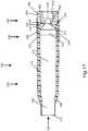
- FIG. 2illustrates an example of a cartridge case 100 not forming part of the present invention.
- the cartridge case 100includes an upper component 200, a lower component 300, and an insert 400.
- the upper component 200 and the lower component 300are made of a polymer
- insert 400is made from a metal, an alloy of metals, or an alloy of a metal and a non-metal. Regardless of materials, the outer dimensions of the cartridge case 100 are within the acceptable tolerances for whatever caliber firearm it will be loaded into.
- the polymer usedis lighter than brass.
- a glass-filled high impact polymercan be used where the glass content is between 0%-50%, preferably between 5% and 50%. In another example the glass content can be 10%.
- An example of a high impact polymer without the glass contentis BASF's Capron ® BU50I.
- the insert 400can be made of steel, and, in an example, heat treated carbon steel, 4140.
- the 4140 steelis further heat treated to a Rockwell "C" scale (“RC") hardness of about 20 to about 50.
- RCRockwell "C" scale
- any carbon steel with similar properties, other metals, metal alloys or metal/non-metal alloyscan be used to form the insert. Heat treating a lower cost steel alloy to improve its strength is a point of distinction from the prior art, which have typically opted for more expensive alloys to deal with the strength and ductility needed for a cartridge casing application.
- the combination of the upper component 200 and the lower component 300are made of 10% glass-filled high impact polymer combined with the insert 400 made of heat treated 4140 steel results in a cartridge that is approximately 50% lighter than a brass formed counterpart.
- This weight savings in the unloaded cartridgeproduces a loaded cartridge of between 25%-30% lighter than the loaded brass cartridge depending on the load used, i.e. which bullet, how much powder, and type of powder used.
- the upper component 200includes a body 202 which transitions into a shoulder 204 that tapers into a neck 206 having a mouth 208 at a first end 210.
- the upper component 200joins the lower component 300 at an opposite, second end 212.
- the lower component 300joins the upper component 200 at a lower component first end 302 (see FIG. 6 ).
- the upper 200 and lower 300 componentsare adhered by an ultraviolet (UV) light or heat cured resin, a spin weld, a laser weld or an ultrasonic weld.
- UVultraviolet
- the lower component 300is joined to the insert 400.
- the upper component 200 and the lower component 300are molded in separate molds. When the lower component 300 is molded, it is molded over the insert 400. This is a partial molding over, since the lower component 300 does not completely cover the insert 400.
- a back end 402 of the insert 400is also the rear end of the casing 100.
- the insert 400is formed with an extraction groove 404 and a rim 406.
- the groove 404 and rim 406are dimensioned to the specific size as dictated by the caliber of the ammunition.
- the insert 400can be formed by turning down bar stock to the specific dimensions or can be cold formed.
- FIG. 3a cross-section of the upper component 200 is illustrated. Because of the nature of the polymer, and the design of the neck 206 and mouth 208, the neck 206 expands uniformly under the gas pressures formed during firing. This concentric expansion provides a smoother release of the projectile into the barrel of the firearm. The smoother release allows for a more stable flight of the projectile, providing greater accuracy and distance with the same amount of powder.
- a sleeve 230begins.
- the sleeve 230in this example, extends approximately to the second end 212.
- the sleeve 230can be an additional thickness to a wall 218 as is normally required for a standard cartridge, or a separately manufactured and adhered to the wall 218.
- the sleeve 230provides additional strength relative to the wall 218 of the body 202 alone. This strengthening, which is in the lateral direction, reduces bending of the upper component 200 of the cartridge case 100.
- the sleeve 230helps to keep the cartridge 100 as concentric as possible, and as noted above, concentricity is a key to accuracy.
- the case wall 218can have a thickness T
- the sleeve 230can have a thickness T+, as illustrated in FIG. 4 .
- the total thickness of the cartridge at the point where there is the wall 218 and sleeve 230is the sum of T and T+.
- the upper portion 220 of the sleeve 230can begin in or near the neck 206 and extend over the shoulder 204.
- the upper portion 220 of the sleeve 230ends against a bullet 50 (see FIG. 1B ) providing additional material, and thus strength, to help retain and align the bullet 50.
- This thickened upper portion 220can act like an extension of the neck 206 farther down into the shoulder.
- the upper portion 220is an advantage over a brass cartridge, since brass cannot be formed in this way. Thus, the upper portion 220 can act to sit and secure the bullet in the same place in the cartridge every time.
- the sleeve 230in the illustrated example of FIGs. 3 , 4 and 5 , extends almost the entire length of the body 202.
- the sleeve 230stops at an overlap potion 222 of the upper component 200.
- the overlap portion 222is the portion of the upper component 200 that engages the lower component 300.
- the overlap portion 222has a thinner wall thickness t, or a second thickness, at the second end 212 than the thickness T of the wall 218 (or T and T+) before the overlap portion 222.
- the second thickness ttapers toward the outside of the upper component 200 so an outer diameter 224 of the wall 218 remains constant while an inner diameter 226 of the wall 218 increases.
- cartridge 100to maintain a constant outer diameter from below the shoulder 204 to the insert 400.
- the bottom end 228 of the sleeve 230is approximately squared off to provide a square shoulder to keep the upper 200 and lower 300 components concentric during assembly.
- FIGs. 6-8illustrate that the lower component 300 has a tapered portion 306 starting at the lower component first end 302 and ending at a collar 308.
- the slope of the tapered portion 306approximately matches the slope of the overlap portion 222 so the two can slide over each other to engage the upper 200 and lower 300 components.
- the tapered portion 306ends in a flat seat 307.
- the seat 307can have a thickness Ts which is about equal to the thickness of the wall and/or sleeve. This allows the bottom end 228 of the sleeve to sit on the seat 307 when the upper 200 and lower 300 components engage. This prevents the bottom end 228 of the sleeve 230 from being exposed. This could allow the gases to exert pressure on the bottom end 228 that can separate the upper 200 from the lower 300 component.
- a width of the collar 308matches the second thickness t, so that the outer diameter of the cartridge 100 remains constant past the transition point between the upper 200 and lower 300 components.
- a thickness of the tapered portion 306is such that at any point the sum of it with the thickness of the overlap portion 222 is approximately equal to the thickness T of the wall 218 or the thicknesses of the wall 218 and sleeve 230 (T and T+). As noted above, the tapered portion 306 and the overlap portion 222 are bonded together to join the upper 200 and lower 300 components.
- An inner wall 310 of the lower component 300can be formed straight.
- the inner wall 310forms a bowl shape with a hole 312 at the bottom.
- the hole 312is formed as a function of the interface between the lower component 300 and the insert 400, and its formation is discussed below.
- the gap 318 that is formed between the inner bowl 314 and the outer sheath 316is the space where a portion of the insert 400 engages the lower component 300.
- the lower component 300is molded over a portion of the insert 400 to join the two parts.
- the insert 400includes an overmolded area 408, where the outer sheath 316 engages the insert 400 in the gap 318.
- the overmolded area 408has one or more ridges 410.
- the ridges 410allow the polymer from the outer sheath 316, during molding, to forms bands 320 (see, FIG. 8 ) in the gap 318.
- the combination of the ridges 410 and bands 320aid in resisting separation between the insert 400 and the lower component 300. The resistance is most important during the extraction of the cartridge from the firearm by an extractor (not illustrated).
- the overmolded area 408also includes one or more keys 412.
- the keys 412are flat surfaces on the ridges 410. These keys 412 prevent the insert 400 and the lower portion 300 from rotating in relation to one another, i.e. the insert 400 twisting around in the lower portion 300.
- a self reinforced area 414is below the overmolded area 408, toward the back end 402, below the overmolded area 408, toward the back end 402, a self reinforced area 414. This portion extends to the back end 402 of the insert 400 and includes the extraction groove 404 and rim 406.
- the self reinforced area 414must, solely by the strength of its materials, withstand the forces exerted by the pressures generated by the gasses when firing the bullet and the forces generated by the extractor. In the present example, the self reinforced area 414 withstands these forces because it is made of a heat treated metal or a metal/non-metal alloy.
- FIGs. 10 and 11illustrate an example of the inside of the insert 400.
- Open along a portion of the back end 402 and continuing partially toward the overmolded area 408is a primer pocket 416.
- the primer pocket 416is dimensioned according to the standards for caliber of the cartridge case and intended use.
- a primer(not illustrated) is seated in the primer pocket 416, and, as described above, when stricken causes an explosive force that ignites the powder (not illustrated) present in the upper 200 and lower 300 components.
- a flash hole 418Forward of the primer pocket 416 is a flash hole 418.
- the flash hole 418is dimensioned according to the standards for the caliber of the cartridge case and intended use.
- the flash hole 418allows the explosive force of the primer, seated in the primer pocket 416, to communicate with the upper 200 and lower 300 components.
- basin 420Forward of the primer pocket 416 and inside the overmolded area 408 is basin 420.
- the basin 420is adjacent to and outside of the inner bowl 314 of the lower component 300.
- the basin 420is bowl shaped, wherein the walls curve inwards toward the bottom.
- the bottom of the basin 420is interrupted by a ring 422.
- the ring 422surrounds the flash hole 418 and extends into the basin 420. It is the presence of the ring 422 that forms the hole 312 in the inner bowl 314 of the lower component 300.
- FIG. 12illustrates a "small upper" embodiment with a bullet 50 in the mouth 208 of the cartridge 120.
- the features of the upper 200 and lower 300 componentare almost identical to the example discussed above, and the insert 400 can be identical.
- FIG. 12also illustrates the engagement between a lip 214 and the cannelure 55.
- the lip 214is a section of the neck 206 approximate to the mouth 208 that has a thicker cross section or, said differently, a portion having a smaller inner diameter than the remainder of the neck 206.
- the lip 214is square or rectangular shaped, no angles or curves in the longitudinal direction.
- the upper component 200is not formed with a lip 214.
- the lip 214engages the cannelure 55 formed along an outer circumferential surface of the bullet 50 when it is fitted into the mouth 208 of the cartridge casing 100.
- FIG. 13shows that the neck 206 and the shoulder 204 are formed similar, but in this example, the body 202 is much shorter. Further, instead of an overlap portion 222, there is an underskirt portion 240 that starts very close to the shoulder 204. The underskirt portion 240 tapers to the inside of the cartridge when it engages the lower component 300.
- the lower component 300 in this further exampleis now much longer and comprises most of the propellant chamber 340.
- the tapered portionis now replaced with an outer tapered portion 342.
- the outer tapered portion 342slides over the underskirt portion 240 so the two can be joined together as noted above.
- the thickness of the underskirt portion 240 and the outer tapered portion 342is approximate to the wall thickness or wall thickness and sleeve thickness.
- the inner wall 310is now substantially longer, can include a sleeve, but still ends in the inner bowl 314.
- the engagement between the second end 304 of the lower component 300 and the insert 400remains the same.
- either the "small upper” or “long upper”can be used to form blank or subsonic ammunition.
- the wallsare made thicker with the sleeve, shrinking the size of the propellant chamber 340. Less powder can be used, but the powder is packed similarly as tight as it is for a live round because of the smaller chamber 340. This can prevent the Secondary Explosive Effect (SEE) (below).
- SEESecondary Explosive Effect
- a large upper component 200having a thicker overlap 222 portion, with a thickness t+ and an integral thickening of the wall, and/or a sleeve 230 with a thickness T+, as disclosed above.
- the total thickness of the wall 218can be the sum of T+ and t+.
- the sleeve 230can run the length of the upper component 200 from the mouth 208 to the start of the overlap portion 222.
- the lower component 300 of a subsonic cartridge 140can be thickened as well.
- the subsonic cartridge 140can be made with the insert 400, or the lower component 300 can be molded in one piece from polymer with the features of the insert 400.
- the insertcan also be high-strength polymer instead of the metal alloys discussed above.
- the lower component and the insertcan be formed as one piece, and the upper component 200 can be placed on top.
- the upper component 200can be made differently.
- an extension 242can be molded to extend from the neck 206.
- the extension 242has a star-shaped cap 244 to seal off the cartridge.
- the cap 244is formed partially of radially spaced fingers 246 that deform outwards during firing.
- the mouth 208is molded partially shut to contain a majority of the pressures and expand open and outwards.
- the fingers 246are designed, in one example, to be bend elastically and are not frangible. The object is to contain the majority of the pressures and expel anything that can act as a projectile out the barrel of the firearm.
- the lower component 300can be filled with the powder and the small upper component can act as a cap to the cartridge, sealing in the powder.
- FIG. 16illustrates an example of a straight wall cartridge 500.
- the straight wall cartridge 500is a one-piece design of all polymer.
- the cartridge 500has a body 502 and a mouth 508 at a first end 510.
- the walls 518 of the cartridge casingcan also have a sleeve 530 along a majority of its length.
- the sleeve 230, 530is dimensioned and shaped pursuant to the requirements of each cartridge based on blank or subsonic and the particular caliber. To that end, the sleeve 530 begins set back from the first end 510 based on the depth the rear of the bullet sits in the cartridge. Further, in this example, as the walls transition into a lower bowl 514, the sleeve 530 may extend into the bowl. This aids in the strength of a back end 512 of the cartridge 500, since this example lacks a hardened metal insert.
- the lower bowl 514curves downward toward a flash hole 517 which then opens to a primer pocket 519. Both are similar to the features described above. Further, the back end is molded to form a rim 506.
- FIG. 17illustrates a cross-section of all three elements engaged together to illustrate how they interface with each other.
- the specific outer dimensions of the three elements and certain inner dimensionsare dictated by the caliber and type of the firearm and type of ammunition.
- the cartridge casing 100 of the present inventionis designed to be used for any and all types of firearms and calibers, including pistols, rifles, manual, semi-automatic, and automatic firearms.
- an exemplary construction of the upper component 200also aids in withstanding the pressures generated.
- the sleeve 230increases the strength of the wall 218 of the upper component 200.
- the upper component 200accounts for anywhere from 70% to 90% of the length of the cartridge casing 100.
- FIG. 18shows a lower narrowed cartridge 1000.
- the lower narrowed cartridge 1000includes an upper component 1200 of the lower narrowed cartridge, a lower component 1300 of the lower narrowed cartridge and an insert 1400 for the lower narrowed cartridge.
- the upper, lower, and insert 1200, 1300, 1400are generally formed as above, except as described further below.
- the upper component 1200has a mouth 1208 in which a bullet 1050 is inserted.
- the mouth 1208is an opening in the neck 1206 of the upper component 1200 and can also contain a lip 1214.
- the lip 1214can engage a cannelure 1055 in the bullet 1050.
- At least one the lip 1214 and the cannelure 1055can be replaced with an adhesive (not illustrated).
- the adhesivecan seal the bullet 1050 in the neck 1206 and provide a waterproofing feature, to prevent moisture from entering between the bullet 1050 and the neck 1206.
- the adhesivealso provides for a control for the amount of force required to project the bullet 1050 out of the cartridge 1000. Controlling this exit force, in certain examples, can be important, since the bullet for sub-sonic ammunition is already "under powered" in relation to a standard round.
- the bullet 1050is a standard weight bullet for its particular caliber.
- the "standard weight" or common weight for a projectilevaries slightly.
- Some examples of standard weightscan include at .223 (5.56) caliber weights between 52 and 90 grains; at .308 and .300 Winchester Magnum calibers weights between 125 and 250 grains; and for .338 Lapua ® Magnum caliber weights between 215 and 300 grains. This can also include standards weights for .50 caliber between 606 and 822 grains.
- the bullet 1050can be less than 125% of maximum standard weight for a particular caliber. Further, the bullet can be less than 120%, 115%, 110% and 105% of the caliber's maximum standard weight.
- the upper component 1200also includes a shoulder 1204.
- the shoulder 1204slopes outward from the neck 1206 and then straightens out to form the upper component outer wall 1217.
- the upper component 2100can join the lower component 1300 as described above, and the lower component 1300 also can have a lower component outer wall 1317.
- the upper and lower component outer walls 1217, 1317can form the outer shape of the cartridge and are shaped as such to fit a standard chamber for the particular caliber.
- Both the upper and lower components 1200, 1300have inner walls 1219, 1319, respectively.
- the inner walls 1219, 1319can form the propellant chamber 1340, which contains the powder or other propellant to discharge the bullet 1050 from the weapon (not illustrated).
- the inner walls 1219, 1319are angled to form a constant slope toward the insert 1400. This narrows, or tapers, the propellant chamber 1340 so the diameter D1 in the upper component 1200 is greater than the diameter D2 closer to the insert 1400.
- a diameter D1 approximate the shoulder 1204can be greater than the diameter D2 (in the lower component 1300) approximate a flash hole 1418 of the insert 1400.
- diameter D2can equal a diameter D3 of the flash hole 1418.
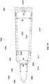
- FIG. 19illustrates another example of a narrowed propellant chamber 1340 not forming part of the present invention.
- the propellant chamber 1340narrows toward the upper component 1200.
- a diameter D4 of the upper component 1200is less than a diameter D5 of the lower component 1300.
- the diameter of the lower component D5can be greater than the diameter D3 of the flash hole 1418.
- the diameter D4 of the upper component 1200is greater than or equal to a diameter D6 of a back of the bullet 1050.
- the cartridge 1000is described in a three-piece design (upper 1200, lower 1300, and insert 1400). Note that the cartridge 1000 can be fabricated in one-piece, all of polymer as described above, or two pieces, a polymer section and the overmolded insert 1400. Additionally, the flash hole 1418 can also be sloped to match the slope of the inner walls 1217, 1317. Further, while the above examples are described with a constant slope from the upper component 1200 to the lower component 1300, other examples can have differing slopes between the two components 1200, 1300 such that one slope is steeper than the other slope. Further, FIGs. 18 and 19 illustrate cartridges wherein the upper component 1200 is smaller than the lower component 1300. The relative sizes of the two components 1200, 1300, can be alternated or they can be equated.
- the slope of the upper component inner wall 1219can differ from the upper component outer wall 1217.
- the samecan be true for the lower component inner wall 1319 differing in slope from the lower component outer wall 1317.
- the polymer construction of the cartridge casealso provides a feature of reduced friction between the cartridge and chamber of the firearm. Reduced friction leads to reduced wear on the chamber, further extending its service life.
- Subsonic ammunitioncan be manufactured using the above illustrated examples.
- Subsonic ammunitionis designed to keep the bullet from breaking the speed of sound (approximately 340 m/s at sea level or less than 1,100 fps). Breaking the speed of sound results in the loud "crack" of a sonic boom, thus subsonic ammunition is much quieter than is standard counterpart.
- Typical subsonic ammunitionuses less powder, to produce less energy, in the same cartridge case as standard ammunition. The remaining space is packed with wadding/filler to keep the powder near the flash hole so it can be ignited by the primer.
- increasing the wall thicknesseliminates the need for wadding.
- a brass cartridge wallcan be 0.0389" thick
- the polymer wall and sleevecan have a total thickness of 0.0879" for the identical caliber.
- the reduced capacityallows for a more efficient ignition of the powder and a higher load density with less powder.
- Low load density(roughly below 30-40%) is one of the main contributors to the Secondary Explosive Effect (SEE).
- SEEcan destroy the strongest rifle action and it can happen on the first shot or the tenth.
- SEEis the result of slow or incomplete ignition of small amounts of smokeless powder.
- the powdersmolders and releases explosive gases which, when finally ignited, detonate in a high order explosion.
- the better sealing effectis also important here because standard brass does not seal the chamber well at the lower pressures created during subsonic shooting.
Landscapes
- Engineering & Computer Science (AREA)
- General Engineering & Computer Science (AREA)
- Portable Nailing Machines And Staplers (AREA)
- Macromolecular Compounds Obtained By Forming Nitrogen-Containing Linkages In General (AREA)
- Filling Or Discharging Of Gas Storage Vessels (AREA)
- Organic Insulating Materials (AREA)
- Pistons, Piston Rings, And Cylinders (AREA)
- Transmission Devices (AREA)
Description
- The present subject matter relates to techniques and equipment to make ammunition articles and, more particularly, to ammunition articles with plastic components such as cartridge casing bodies and bases for at least blank and subsonic ammunition.
- It is well known in the industry to manufacture bullets and corresponding cartridge cases from either brass or steel. Typically, industry design calls for materials that are strong enough to withstand extreme operating pressures and which can be formed into a cartridge case to hold the bullet, while simultaneously resist rupturing during the firing process.
- Conventional ammunition typically includes four basic components, that is, the bullet, the cartridge case holding the bullet therein, a propellant used to push the bullet down the barrel at predetermined velocities, and a primer, which provides the spark needed to ignite the powder which sets the bullet in motion down the barrel.
- The cartridge case is typically formed from brass and is configured to hold the bullet therein to create a predetermined resistance, which is known in the industry as bullet pull. The cartridge case is also designed to contain the propellant media as well as the primer.
- However, brass is heavy, expensive, and potentially hazardous. For example, the weight of 0.50 caliber ammunition is about 60 pounds per box (200 cartridges plus links).
- The bullet is configured to fit within an open end or mouth of the cartridge case and conventionally includes a groove (hereinafter referred to as a cannelure) formed in the mid section of the bullet to accept a crimping action imparted to the metallic cartridge case therein. When the crimped portion of the cartridge case holds the bullet by locking into the cannelure, a bullet pull value is provided representing a predetermined tension at which the cartridge case holds the bullet. The bullet pull value, in effect, assists imparting a regulated pressure and velocity to the bullet when the bullet leaves the cartridge case and travels down the barrel of a gun.
- Furthermore, the bullet is typically manufactured from a soft material, such as, for example only, lead, wherein the bullet accepts the mouth of the cartridge being crimped to any portion of the bullet to hold the bullet in place in the cartridge case, even though the cartridge case is crimped to the cannelure of the bullet.
- However, one drawback of this design is that the crimped neck does not release from around the bullet evenly when fired. This leads to uncertain performance from round to round. Pressures can build up unevenly and alter the accuracy of the bullet.
- The propellant is typically a solid chemical compound in powder form commonly referred to as smokeless powder. Propellants are selected such that when confined within the cartridge case, the propellant bums at a known and predictably rapid rate to produce the desired expanding gases. As discussed above, the expanding gases of the propellant provide the energy force that launches the bullet from the grasp of the cartridge case and propels the bullet down the barrel of the gun at a known and relatively high velocity.
- The primer is the smallest of the four basic components used to form conventional ammunition. As discussed above, primers provide the spark needed to ignite the powder that sets the bullet in motion down the barrel. The primer includes a relatively small metal cup containing a priming mixture, foil paper, and relatively small metal post, commonly referred to as an anvil.
- When a firing pin of a gun or firearm strikes a casing of the primer, the anvil is crushed to ignite the priming mixture contained in the metal cup of the primer. Typically, the primer mixture is an explosive lead styphnate blended with non-corrosive fuels and oxidizers which bums through a flash hole formed in the rear area of the cartridge case and ignites the propellant stored in the cartridge case. In addition to igniting the propellant, the primer produces an initial pressure to support the burning propellant and seals the rear of the cartridge case to prevent high-pressure gases from escaping rearward. It should be noted that it is well known in the industry to manufacture primers in several different sizes and from different mixtures, each of which affects ignition differently.
- The cartridge case, which is typically metallic, acts as a payload delivery vessel and can have several body shapes and head configurations, depending on the caliber of the ammunition. Despite the different body shapes and head configurations, all cartridge cases have a feature used to guide the cartridge case, with a bullet held therein, into the chamber of the gun or firearm.
- The primary objective of the cartridge case is to hold the bullet, primer, and propellant therein until the gun is fired. Upon firing of the gun, the cartridge case seals the chamber to prevent the hot gases from escaping the chamber in a rearward direction and harming the shooter. The empty cartridge case is extracted manually or with the assistance of gas or recoil from the chamber once the gun is fired.
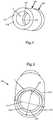
- As shown in
FIG. 1A , abottleneck cartridge case 10 has abody 11 formed with ashoulder 12 that tapers into aneck 13 having a mouth at a first end. Aprimer holding chamber 15 is formed at a second end of the body opposite the first end. Adivider 16 separates a main cartridgecase holding chamber 17, which contains a propellant, from theprimer holding chamber 15, which communicate with each other via aflash hole channel 18 formed in theweb area 16. An exterior circumferential region of the rear end of the cartridge case includes anextraction groove 19a and arim 19b. - Prior art patents in this area include
U.S. Patent No. 4,147,107 to Ringdal ,U.S. Patent No. 6,845,716 to Husseini et al. ,U.S. Patent No. 7,213,519 to Wiley et al. , andU.S. Patent No. 7,610,858 to Chung . The four patents are directed to an ammunition cartridge suitable for rifles or guns and including a cartridge case made of at least a plastics material. However, each have their own drawbacks. - Further, the use of brass cartridges for blank or subsonic ammunition can be problematic. To reduce the velocity of the bullet exiting the cartridge, typically less propellant is used in comparison to when the bullet is traveling at its top velocity. However, the same size cartridge needs to be used so the bullet can be fired from a standard firearm. An empty space is left inside a blank or subsonic cartridge where the propellant would normally reside. To compensate, wadding (typically cotton) can be packed into the space normally filled by the propellant. This wadding can cause problems with the use of the round, including jamming the firearm and fouling silencers and/or suppressors attached to the firearm.
- Other inventions attempting to address this issue include
U.S. Patent No. 6,283,035 to Olsen , which places an expanding insert into a brass cartridge, andU.S. Patent Application Publication No. 2003/0019385 to LeaSure which uses a heavier than standard bullet with a reduced capacity cartridge. - Hence, a need exists for a polymer casing that can perform as well as or better than the brass alternative. A further improvement is polymer casings that are capable of production in a more conventional and cost effective manner, i.e. by using standard loading presses. Additionally, the cartridge can provide increased performance for blank and subsonic rounds by reducing the capacity of the cartridge, but still use standard weight bullets.
US3990366 discloses a high strenght polymer-based cartridge casing according to the preamble of claim 1.- The teachings herein alleviate one or more of the above noted problems with the strength and formation of polymer based cartridges.
- A high strength polymer-based cartridge casing includes an upper component of polymer, a bullet of a standard weight, a lower component of polymer, and an insert. The upper component has a shoulder portion and an upper component inner wall has a first slope extending from the shoulder. The lower component has a lower component inner wall having a second slope. The upper and lower component inner walls form a propellant chamber; and the first and second slopes reduce a volume of the propellant chamber. The reduced volume of the propellant chamber permits only enough propellant to propel a bullet engaged in the cartridge casing at subsonic speeds. For the high strength polymer-based cartridge casing, the standard weight of the bullet is less than one of 125%, 120%, 115%, 110%, and 105% of a maximum weight of the bullet at a particular caliber.
- In an example, the first slope equals the second slope. In another example, the first slope does not equal the second slope. Further, according to the invention, the first slope and the second slope narrow the propellant chamber as the first and second slopes progress toward the insert.
- The high strength polymer-based cartridge casing can also have a first diameter of the upper component inner wall, and a second diameter of the lower component inner wall. In an example, the first diameter is greater than the second diameter. For another example, the first diameter is less than the second diameter.
- As a result, a light weight, high strength cartridge case can be formed using standard brass cartridge loading equipment. As noted below, the present invention can be adapted to any type of cartridge, caliber, powder load, or primer. Calibers can range at least between .22 and 30 mm and accept any type of bullet that can be loaded in a typical brass cartridge.
- Further advantages can be gained in both blank and subsonic ammunition due to the removal of wadding and the shrinking of the volume of powder based on a reduced volume in the cartridge.
- The polymer used can be of any known polymer and additives, but the present invention uses a nylon polymer with glass fibers. Further, the portion of the cartridge that engages the extractor of the firearm can be made from heat strengthened steel for normal loads and can be a continuous molded polymer piece of the lower component for either subsonic or blank ammunition.
- Additional advantages and novel features will be set forth in part in the description which follows, and in part will become apparent to those skilled in the art upon examination of the following and the accompanying drawings or may be learned by production or operation of the examples. The advantages of the present teachings may be realized and attained by practice or use of various aspects of the methodologies, instrumentalities and combinations set forth in the detailed examples discussed below.
- The drawing figures depict one or more implementations in accord with the present teachings, by way of example only, not by way of limitation. In the figures, like reference numerals refer to the same or similar elements.
FIG. 1A is a cross sectional view of a conventional bottleneck cartridge case;FIG. 1B is a side view of a conventional bullet;FIG. 2 is a side perspective view of the outside of cartridge case which does not form part of the present invention;FIG. 3 is a longitudinal cross-section of the upper component of the cartridge;FIG. 4 is a bottom, side, perspective, radial cross-section of the upper and lower components of the cartridge;FIG. 5 is an end view of the upper component without the lower component and insert;FIG. 6 is a side view of the lower component without the upper component and insert;FIG. 7 is a bottom front perspective view of the lower component ofFIG. 6 ;FIG. 8 is a longitudinal cross-section view of the lower component ofFIG. 6 ;FIG. 9 is a side view of the insert without the upper and lower components;FIG. 10 is a bottom front perspective view of the insert ofFIG. 8 ;FIG. 11 is a longitudinal cross-section view of the insert ofFIG. 8 ;FIG. 12 is a longitudinal cross-section view of an example of a cartridge case;FIG. 13 is a top, side, perspective view of the upper component of the example;FIG. 14 is a top, side perspective view of an example of an upper component of a subsonic cartridge;FIG. 15 is a top, side perspective view of an upper component for a blank cartridge;FIG. 16 is a longitudinal cross-section view of an example of a straight wall cartridge case;FIG. 17 is a longitudinal cross-section view of the cartridge case ofFIG. 2 ;FIG. 18 is a longitudinal cross-section view of an example of a tapered wall cartridge case according to the invention; andFIG. 19 is a longitudinal cross-section view of another example of a tapered wall cartridge case not forming part of the invention.- In the following detailed description, numerous specific details are set forth by way of examples in order to provide a thorough understanding of the relevant teachings. However, it should be apparent to those skilled in the art that the present teachings may be practiced without such details. In other instances, well known methods, procedures, components, and/or circuitry have been described at a relatively high-level, without detail, in order to avoid unnecessarily obscuring aspects of the present teachings.
- The present invention provides a cartridge case body strong enough to withstand gas pressures that equal or surpass the strength of brass cartridge cases under certain conditions, e.g. for both storage and handling.
- Reference now is made in detail to the examples illustrated in the accompanying drawings and discussed below.
FIG. 2 illustrates an example of acartridge case 100 not forming part of the present invention. Thecartridge case 100 includes anupper component 200, alower component 300, and aninsert 400. In this example, theupper component 200 and thelower component 300 are made of a polymer, whileinsert 400 is made from a metal, an alloy of metals, or an alloy of a metal and a non-metal. Regardless of materials, the outer dimensions of thecartridge case 100 are within the acceptable tolerances for whatever caliber firearm it will be loaded into. - The polymer used is lighter than brass. A glass-filled high impact polymer can be used where the glass content is between 0%-50%, preferably between 5% and 50%. In another example the glass content can be 10%. An example of a high impact polymer without the glass content is BASF's Capron® BU50I. The
insert 400 can be made of steel, and, in an example, heat treated carbon steel, 4140. The 4140 steel is further heat treated to a Rockwell "C" scale ("RC") hardness of about 20 to about 50. However, any carbon steel with similar properties, other metals, metal alloys or metal/non-metal alloys can be used to form the insert. Heat treating a lower cost steel alloy to improve its strength is a point of distinction from the prior art, which have typically opted for more expensive alloys to deal with the strength and ductility needed for a cartridge casing application. - In an example, the combination of the
upper component 200 and thelower component 300 are made of 10% glass-filled high impact polymer combined with theinsert 400 made of heat treated 4140 steel results in a cartridge that is approximately 50% lighter than a brass formed counterpart. This weight savings in the unloaded cartridge produces a loaded cartridge of between 25%-30% lighter than the loaded brass cartridge depending on the load used, i.e. which bullet, how much powder, and type of powder used. - The
upper component 200 includes abody 202 which transitions into ashoulder 204 that tapers into aneck 206 having amouth 208 at afirst end 210. Theupper component 200 joins thelower component 300 at an opposite,second end 212. Thelower component 300 joins theupper component 200 at a lower component first end 302 (seeFIG. 6 ). The upper 200 and lower 300 components are adhered by an ultraviolet (UV) light or heat cured resin, a spin weld, a laser weld or an ultrasonic weld. - At a
second end 304 of thelower component 300, the lower component is joined to theinsert 400. In one example, theupper component 200 and thelower component 300 are molded in separate molds. When thelower component 300 is molded, it is molded over theinsert 400. This is a partial molding over, since thelower component 300 does not completely cover theinsert 400. - A
back end 402 of theinsert 400 is also the rear end of thecasing 100. Theinsert 400 is formed with anextraction groove 404 and arim 406. Thegroove 404 andrim 406 are dimensioned to the specific size as dictated by the caliber of the ammunition. Theinsert 400 can be formed by turning down bar stock to the specific dimensions or can be cold formed. - Turning now to
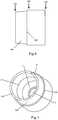
FIG. 3 , a cross-section of theupper component 200 is illustrated. Because of the nature of the polymer, and the design of theneck 206 andmouth 208, theneck 206 expands uniformly under the gas pressures formed during firing. This concentric expansion provides a smoother release of the projectile into the barrel of the firearm. The smoother release allows for a more stable flight of the projectile, providing greater accuracy and distance with the same amount of powder. - Moving toward the
second end 212 of theupper component 200, as theneck 206 transitions into theshoulder 204, asleeve 230 begins. Thesleeve 230, in this example, extends approximately to thesecond end 212. Thesleeve 230 can be an additional thickness to awall 218 as is normally required for a standard cartridge, or a separately manufactured and adhered to thewall 218. Thesleeve 230 provides additional strength relative to thewall 218 of thebody 202 alone. This strengthening, which is in the lateral direction, reduces bending of theupper component 200 of thecartridge case 100. Thesleeve 230 helps to keep thecartridge 100 as concentric as possible, and as noted above, concentricity is a key to accuracy. - The
case wall 218 can have a thickness T, and thesleeve 230 can have a thickness T+, as illustrated inFIG. 4 . Thus, the total thickness of the cartridge at the point where there is thewall 218 andsleeve 230 is the sum of T and T+. - The
upper portion 220 of thesleeve 230 can begin in or near theneck 206 and extend over theshoulder 204. In one example, theupper portion 220 of thesleeve 230 ends against a bullet 50 (seeFIG. 1B ) providing additional material, and thus strength, to help retain and align thebullet 50. This thickenedupper portion 220 can act like an extension of theneck 206 farther down into the shoulder. Theupper portion 220 is an advantage over a brass cartridge, since brass cannot be formed in this way. Thus, theupper portion 220 can act to sit and secure the bullet in the same place in the cartridge every time. - The
sleeve 230, in the illustrated example ofFIGs. 3 ,4 and 5 , extends almost the entire length of thebody 202. Thesleeve 230 stops at anoverlap potion 222 of theupper component 200. Theoverlap portion 222 is the portion of theupper component 200 that engages thelower component 300. Theoverlap portion 222 has a thinner wall thickness t, or a second thickness, at thesecond end 212 than the thickness T of the wall 218 (or T and T+) before theoverlap portion 222. The second thickness t tapers toward the outside of theupper component 200 so an outer diameter 224 of thewall 218 remains constant while aninner diameter 226 of thewall 218 increases. This allows certain examples ofcartridge 100 to maintain a constant outer diameter from below theshoulder 204 to theinsert 400. Thebottom end 228 of thesleeve 230 is approximately squared off to provide a square shoulder to keep the upper 200 and lower 300 components concentric during assembly. FIGs. 6-8 illustrate that thelower component 300 has a taperedportion 306 starting at the lower componentfirst end 302 and ending at acollar 308. The slope of the taperedportion 306 approximately matches the slope of theoverlap portion 222 so the two can slide over each other to engage the upper 200 and lower 300 components. The taperedportion 306 ends in aflat seat 307. Theseat 307 can have a thickness Ts which is about equal to the thickness of the wall and/or sleeve. This allows thebottom end 228 of the sleeve to sit on theseat 307 when the upper 200 and lower 300 components engage. This prevents thebottom end 228 of thesleeve 230 from being exposed. This could allow the gases to exert pressure on thebottom end 228 that can separate the upper 200 from the lower 300 component.- A width of the
collar 308 matches the second thickness t, so that the outer diameter of thecartridge 100 remains constant past the transition point between the upper 200 and lower 300 components. Further, a thickness of the taperedportion 306 is such that at any point the sum of it with the thickness of theoverlap portion 222 is approximately equal to the thickness T of thewall 218 or the thicknesses of thewall 218 and sleeve 230 (T and T+). As noted above, the taperedportion 306 and theoverlap portion 222 are bonded together to join the upper 200 and lower 300 components. - An
inner wall 310 of thelower component 300 can be formed straight. In the illustrated example inFIG. 8 , theinner wall 310 forms a bowl shape with ahole 312 at the bottom. Thehole 312 is formed as a function of the interface between thelower component 300 and theinsert 400, and its formation is discussed below. As theinner wall 310 slopes inward to form the bowl shape, it forks and forms aninner bowl 314 and anouter sheath 316. Thegap 318 that is formed between theinner bowl 314 and theouter sheath 316 is the space where a portion of theinsert 400 engages thelower component 300. As noted above, in one example, thelower component 300 is molded over a portion of theinsert 400 to join the two parts. - Turning now to an example of the
insert 400, as illustrated inFIG. 9 , it includes anovermolded area 408, where theouter sheath 316 engages theinsert 400 in thegap 318. Theovermolded area 408 has one ormore ridges 410. Theridges 410 allow the polymer from theouter sheath 316, during molding, to forms bands 320 (see,FIG. 8 ) in thegap 318. The combination of theridges 410 andbands 320 aid in resisting separation between theinsert 400 and thelower component 300. The resistance is most important during the extraction of the cartridge from the firearm by an extractor (not illustrated). - The
overmolded area 408 also includes one ormore keys 412. Thekeys 412 are flat surfaces on theridges 410. Thesekeys 412 prevent theinsert 400 and thelower portion 300 from rotating in relation to one another, i.e. theinsert 400 twisting around in thelower portion 300. - Below the
overmolded area 408, toward theback end 402, is a self reinforcedarea 414. This portion extends to theback end 402 of theinsert 400 and includes theextraction groove 404 andrim 406. The self reinforcedarea 414 must, solely by the strength of its materials, withstand the forces exerted by the pressures generated by the gasses when firing the bullet and the forces generated by the extractor. In the present example, the self reinforcedarea 414 withstands these forces because it is made of a heat treated metal or a metal/non-metal alloy. FIGs. 10 and 11 illustrate an example of the inside of theinsert 400. Open along a portion of theback end 402 and continuing partially toward theovermolded area 408 is aprimer pocket 416. Theprimer pocket 416 is dimensioned according to the standards for caliber of the cartridge case and intended use. A primer (not illustrated) is seated in theprimer pocket 416, and, as described above, when stricken causes an explosive force that ignites the powder (not illustrated) present in the upper 200 and lower 300 components.- Forward of the
primer pocket 416 is aflash hole 418. Again, theflash hole 418 is dimensioned according to the standards for the caliber of the cartridge case and intended use. Theflash hole 418 allows the explosive force of the primer, seated in theprimer pocket 416, to communicate with the upper 200 and lower 300 components. - Forward of the
primer pocket 416 and inside theovermolded area 408 isbasin 420. Thebasin 420 is adjacent to and outside of theinner bowl 314 of thelower component 300. Thebasin 420 is bowl shaped, wherein the walls curve inwards toward the bottom. The bottom of thebasin 420 is interrupted by aring 422. Thering 422 surrounds theflash hole 418 and extends into thebasin 420. It is the presence of thering 422 that forms thehole 312 in theinner bowl 314 of thelower component 300. - In another example of a cartridge case 120, the sizes of the upper 200 and lower 300 components can be altered.
FIG. 12 illustrates a "small upper" embodiment with abullet 50 in themouth 208 of the cartridge 120. The features of the upper 200 and lower 300 component are almost identical to the example discussed above, and theinsert 400 can be identical.FIG. 12 also illustrates the engagement between alip 214 and thecannelure 55. Thelip 214 is a section of theneck 206 approximate to themouth 208 that has a thicker cross section or, said differently, a portion having a smaller inner diameter than the remainder of theneck 206. In this example, thelip 214 is square or rectangular shaped, no angles or curves in the longitudinal direction. Note, in other examples, theupper component 200 is not formed with alip 214. When present, thelip 214 engages thecannelure 55 formed along an outer circumferential surface of thebullet 50 when it is fitted into themouth 208 of thecartridge casing 100. FIG. 13 shows that theneck 206 and theshoulder 204 are formed similar, but in this example, thebody 202 is much shorter. Further, instead of anoverlap portion 222, there is anunderskirt portion 240 that starts very close to theshoulder 204. Theunderskirt portion 240 tapers to the inside of the cartridge when it engages thelower component 300.- The
lower component 300 in this further example, is now much longer and comprises most of thepropellant chamber 340. The tapered portion is now replaced with an outertapered portion 342. The outer taperedportion 342 slides over theunderskirt portion 240 so the two can be joined together as noted above. The thickness of theunderskirt portion 240 and the outer taperedportion 342 is approximate to the wall thickness or wall thickness and sleeve thickness. - The
inner wall 310 is now substantially longer, can include a sleeve, but still ends in theinner bowl 314. The engagement between thesecond end 304 of thelower component 300 and theinsert 400 remains the same. Note that either the "small upper" or "long upper" can be used to form blank or subsonic ammunition. The walls are made thicker with the sleeve, shrinking the size of thepropellant chamber 340. Less powder can be used, but the powder is packed similarly as tight as it is for a live round because of thesmaller chamber 340. This can prevent the Secondary Explosive Effect (SEE) (below). A thick wall design for asubsonic cartridge 140 is illustrated inFIG. 14 . - Illustrated is a large
upper component 200 having athicker overlap 222 portion, with a thickness t+ and an integral thickening of the wall, and/or asleeve 230 with a thickness T+, as disclosed above. The total thickness of thewall 218 can be the sum of T+ and t+. Thesleeve 230 can run the length of theupper component 200 from themouth 208 to the start of theoverlap portion 222. Thelower component 300 of asubsonic cartridge 140 can be thickened as well. Thesubsonic cartridge 140 can be made with theinsert 400, or thelower component 300 can be molded in one piece from polymer with the features of theinsert 400. For example, theflash hole 418,primer pocket 416,groove 404 andrim 406. Alternately, the insert can also be high-strength polymer instead of the metal alloys discussed above. In this example, the lower component and the insert can be formed as one piece, and theupper component 200 can be placed on top. - As illustrated in
FIG. 15 , for ablank cartridge 150, theupper component 200 can be made differently. For theblank cartridge 150, anextension 242 can be molded to extend from theneck 206. Theextension 242 has a star-shapedcap 244 to seal off the cartridge. Thecap 244 is formed partially of radially spacedfingers 246 that deform outwards during firing. Thus, themouth 208 is molded partially shut to contain a majority of the pressures and expand open and outwards. Thefingers 246 are designed, in one example, to be bend elastically and are not frangible. The object is to contain the majority of the pressures and expel anything that can act as a projectile out the barrel of the firearm. - When the
blank cartridge 150 is formed with the "small upper"component 200 with thecap 244, thelower component 300 can be filled with the powder and the small upper component can act as a cap to the cartridge, sealing in the powder. - Note that the above examples illustrate a bottleneck cartridge. Many of the features above can be used with any cartridge style, including straight wall cartridges used in pistols.
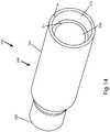
FIG. 16 illustrates an example of astraight wall cartridge 500. Thestraight wall cartridge 500 is a one-piece design of all polymer. Thecartridge 500 has abody 502 and amouth 508 at afirst end 510. Thewalls 518 of the cartridge casing can also have a sleeve 530 along a majority of its length. - The
sleeve 230, 530 is dimensioned and shaped pursuant to the requirements of each cartridge based on blank or subsonic and the particular caliber. To that end, the sleeve 530 begins set back from thefirst end 510 based on the depth the rear of the bullet sits in the cartridge. Further, in this example, as the walls transition into alower bowl 514, the sleeve 530 may extend into the bowl. This aids in the strength of aback end 512 of thecartridge 500, since this example lacks a hardened metal insert. - The
lower bowl 514 curves downward toward aflash hole 517 which then opens to aprimer pocket 519. Both are similar to the features described above. Further, the back end is molded to form arim 506. - Turning now to an example of a fully formed
cartridge case 100,FIG. 17 illustrates a cross-section of all three elements engaged together to illustrate how they interface with each other. The specific outer dimensions of the three elements and certain inner dimensions (e.g. mouth 208,lip 214,flash hole 418, and primer pocket 416) are dictated by the caliber and type of the firearm and type of ammunition. Thecartridge casing 100 of the present invention is designed to be used for any and all types of firearms and calibers, including pistols, rifles, manual, semi-automatic, and automatic firearms. - An exemplary construction of the
upper component 200 also aids in withstanding the pressures generated. As noted above, thesleeve 230 increases the strength of thewall 218 of theupper component 200. In the present example, theupper component 200 accounts for anywhere from 70% to 90% of the length of thecartridge casing 100. - According to the invention, a reduced capacity cartridge case is illustrated in
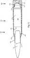
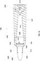
FIG. 18 which shows a lowernarrowed cartridge 1000. The lower narrowedcartridge 1000 includes anupper component 1200 of the lower narrowed cartridge, alower component 1300 of the lower narrowed cartridge and aninsert 1400 for the lower narrowed cartridge. The upper, lower, andinsert upper component 1200 has amouth 1208 in which abullet 1050 is inserted. Themouth 1208 is an opening in theneck 1206 of theupper component 1200 and can also contain alip 1214. Thelip 1214 can engage acannelure 1055 in thebullet 1050. - Further, at least one the
lip 1214 and thecannelure 1055 can be replaced with an adhesive (not illustrated). The adhesive can seal thebullet 1050 in theneck 1206 and provide a waterproofing feature, to prevent moisture from entering between thebullet 1050 and theneck 1206. The adhesive also provides for a control for the amount of force required to project thebullet 1050 out of thecartridge 1000. Controlling this exit force, in certain examples, can be important, since the bullet for sub-sonic ammunition is already "under powered" in relation to a standard round. - The
bullet 1050 is a standard weight bullet for its particular caliber. The "standard weight" or common weight for a projectile varies slightly. Some examples of standard weights can include at .223 (5.56) caliber weights between 52 and 90 grains; at .308 and .300 Winchester Magnum calibers weights between 125 and 250 grains; and for .338 Lapua® Magnum caliber weights between 215 and 300 grains. This can also include standards weights for .50 caliber between 606 and 822 grains. Thebullet 1050 can be less than 125% of maximum standard weight for a particular caliber. Further, the bullet can be less than 120%, 115%, 110% and 105% of the caliber's maximum standard weight. - The
upper component 1200 also includes ashoulder 1204. Theshoulder 1204 slopes outward from theneck 1206 and then straightens out to form the upper componentouter wall 1217. The upper component 2100 can join thelower component 1300 as described above, and thelower component 1300 also can have a lower componentouter wall 1317. The upper and lower componentouter walls - Both the upper and
lower components inner walls inner walls propellant chamber 1340, which contains the powder or other propellant to discharge thebullet 1050 from the weapon (not illustrated). Theinner walls insert 1400. This narrows, or tapers, thepropellant chamber 1340 so the diameter D1 in theupper component 1200 is greater than the diameter D2 closer to theinsert 1400. It can be further said that, in an example, a diameter D1 approximate theshoulder 1204 can be greater than the diameter D2 (in the lower component 1300) approximate aflash hole 1418 of theinsert 1400. In another example, diameter D2 can equal a diameter D3 of theflash hole 1418. FIG. 19 illustrates another example of a narrowedpropellant chamber 1340 not forming part of the present invention. In this example, thepropellant chamber 1340 narrows toward theupper component 1200. Thus, a diameter D4 of theupper component 1200 is less than a diameter D5 of thelower component 1300. Additionally, the diameter of the lower component D5 can be greater than the diameter D3 of theflash hole 1418. In one example, the diameter D4 of theupper component 1200 is greater than or equal to a diameter D6 of a back of thebullet 1050.- In the above examples, the
cartridge 1000 is described in a three-piece design (upper 1200, lower 1300, and insert 1400). Note that thecartridge 1000 can be fabricated in one-piece, all of polymer as described above, or two pieces, a polymer section and theovermolded insert 1400. Additionally, theflash hole 1418 can also be sloped to match the slope of theinner walls upper component 1200 to thelower component 1300, other examples can have differing slopes between the twocomponents FIGs. 18 and19 illustrate cartridges wherein theupper component 1200 is smaller than thelower component 1300. The relative sizes of the twocomponents - Further, the slope of the upper component
inner wall 1219 can differ from the upper componentouter wall 1217. The same can be true for the lower componentinner wall 1319 differing in slope from the lower componentouter wall 1317. - The polymer construction of the cartridge case also provides a feature of reduced friction between the cartridge and chamber of the firearm. Reduced friction leads to reduced wear on the chamber, further extending its service life.
- Subsonic ammunition can be manufactured using the above illustrated examples. Subsonic ammunition is designed to keep the bullet from breaking the speed of sound (approximately 340 m/s at sea level or less than 1,100 fps). Breaking the speed of sound results in the loud "crack" of a sonic boom, thus subsonic ammunition is much quieter than is standard counterpart. Typical subsonic ammunition uses less powder, to produce less energy, in the same cartridge case as standard ammunition. The remaining space is packed with wadding/filler to keep the powder near the flash hole so it can be ignited by the primer. As noted above, increasing the wall thickness eliminates the need for wadding. In one example, while a brass cartridge wall can be 0.0389" thick, the polymer wall and sleeve can have a total thickness of 0.0879" for the identical caliber.
- The reduced capacity allows for a more efficient ignition of the powder and a higher load density with less powder. Low load density (roughly below 30-40%) is one of the main contributors to the Secondary Explosive Effect (SEE). SEE can destroy the strongest rifle action and it can happen on the first shot or the tenth. SEE is the result of slow or incomplete ignition of small amounts of smokeless powder. The powder smolders and releases explosive gases which, when finally ignited, detonate in a high order explosion. The better sealing effect is also important here because standard brass does not seal the chamber well at the lower pressures created during subsonic shooting.
Claims (15)
- A high strength polymer-based cartridge casing (1000) for at least one of blank or subsonic ammunition comprising:an upper component (1200), molded from a polymer, comprising:a first end (210) having a mouth (1208);a shoulder portion (1204);at least an upper inner wall (218, 1219) between the first end and a second end (212) of the upper component (1200) opposite the first end (210); andat least one of an overlap portion and a underskirt portion (222) extending fromthe wall (218, 1219) near the second end (212);a lower component (1300), molded from a polymer, comprising:at least one of a tapered portion and an outer tapered portion (306) that engages at least one of the overlap portion and the underskirt portion (222), respectively, to join the upper and the lower components; andat least a lower inner wall (310, 1319) between the upper component (200) and an flash hole (418);an insert (1400) engaged to the lower component;said upper inner wall having a first slope extending from the shoulder (1204) and directed toward the lower component (1300) and said lower inner wall (1319) having a second slope extending from the upper component toward the insert (1400);characterized in that the upper inner wall and the lower inner wall slope to reduce a volume of a propellant chamber (1340) formed by the upper and lower inner walls andcharacterized in that said first slope and said second slope narrow the propellant chamber progressing toward the insert.
- The high strength polymer-based cartridge casing of claim 1, wherein the reduced volume of the propellant chamber permits only enough propellant to propel a bullet (1050) engaged in the cartridge casing at subsonic speeds.
- The high strength polymer-based cartridge casing of claim 1, wherein the upper component further comprises:an extension engaged at the mouth; anda cap (244) engaged to an end of the extension opposite the mouth;wherein the cap elastically deforms when the cartridge is fired.
- The high strength polymer-based cartridge casing of claim 1, wherein the length of the upper component is greater than the length of the lower component.
- The high strength polymer-based cartridge casing of claim 1, wherein the length of the lower component is greater than the length of the upper component.
- A blank or subsonic ammunition comprising:a high strength polymer-based cartridge casing according to one of the claims 1 to 5;a bullet (1050), having a standard weight, removably engaged with the upper component.
- The blank or subsonic ammunition of claim 6, wherein the reduced volume of the propellant chamber permits only enough propellant to propel the bullet at subsonic speeds.
- The blank or subsonic ammunition of claim 6, wherein the standard weight of the bullet is less than one of 125%, 120%, 115%, 110%, and 105% of a maximum weight of the bullet at a particular caliber.
- The blank or subsonic ammunition of claim 6, wherein the first slope equals the second slope.
- The blank or subsonic ammunition of claim 6, wherein the first slope does not equal the second slope.
- The blank or subsonic ammunition of claim 6, wherein the first slope and the second slope narrow the propellant chamber as the first and second slopes progress toward the insert.
- The blank or subsonic ammunition of claim 6, wherein the first slope and the second slope narrow the propellant chamber as the first and second slopes progress toward the shoulder.
- The blank or subsonic ammunition of claim 6, further comprising:a first diameter of the upper component inner wall; anda second diameter of the lower component inner wall;wherein the first diameter is greater than the second diameter.
- The blank or subsonic ammunition of claim 6, further comprising:a first diameter(D1) of the upper component inner wall; anda second diameter (D2) of the lower component inner wall;wherein the first diameter is less than the second diameter.
- The blank or subsonic ammunition of claim 6, further comprising an adhesive disposed between the bullet and the upper component.
Applications Claiming Priority (2)
| Application Number | Priority Date | Filing Date | Title |
|---|---|---|---|
| US13/549,351US8763535B2 (en) | 2011-01-14 | 2012-07-13 | Narrowing high strength polymer-based cartridge casing for blank and subsonic ammunition |
| PCT/US2013/050358WO2014062256A2 (en) | 2012-07-13 | 2013-07-12 | Narrowing high strength polymer-based cartridge casing for blank and subsonic ammunition |
Publications (2)
| Publication Number | Publication Date |
|---|---|
| EP2872851A2 EP2872851A2 (en) | 2015-05-20 |
| EP2872851B1true EP2872851B1 (en) | 2017-05-24 |
Family
ID=50071696
Family Applications (1)
| Application Number | Title | Priority Date | Filing Date |
|---|---|---|---|
| EP13828955.8AActiveEP2872851B1 (en) | 2012-07-13 | 2013-07-12 | Narrowing high strength polymer-based cartridge casing for blank and subsonic ammunition |
Country Status (3)
| Country | Link |
|---|---|
| EP (1) | EP2872851B1 (en) |
| IL (9) | IL308266B2 (en) |
| WO (1) | WO2014062256A2 (en) |
Cited By (1)
| Publication number | Priority date | Publication date | Assignee | Title |
|---|---|---|---|---|
| US12066279B2 (en) | 2022-05-06 | 2024-08-20 | Innovative Performance Applications, Llc | Polymer ammunition casing |
Families Citing this family (100)
| Publication number | Priority date | Publication date | Assignee | Title |
|---|---|---|---|---|
| US9644930B1 (en) | 2010-11-10 | 2017-05-09 | True Velocity, Inc. | Method of making polymer ammunition having a primer diffuser |
| US10041770B2 (en) | 2010-11-10 | 2018-08-07 | True Velocity, Inc. | Metal injection molded ammunition cartridge |
| US11231257B2 (en) | 2010-11-10 | 2022-01-25 | True Velocity Ip Holdings, Llc | Method of making a metal injection molded ammunition cartridge |
| US9885551B2 (en) | 2010-11-10 | 2018-02-06 | True Velocity, Inc. | Subsonic polymeric ammunition |
| US11118875B1 (en) | 2010-11-10 | 2021-09-14 | True Velocity Ip Holdings, Llc | Color coded polymer ammunition cartridge |
| US11293732B2 (en) | 2010-11-10 | 2022-04-05 | True Velocity Ip Holdings, Llc | Method of making polymeric subsonic ammunition |
| US10048052B2 (en) | 2010-11-10 | 2018-08-14 | True Velocity, Inc. | Method of making a polymeric subsonic ammunition cartridge |
| US10352670B2 (en) | 2010-11-10 | 2019-07-16 | True Velocity Ip Holdings, Llc | Lightweight polymer ammunition cartridge casings |
| US11209252B2 (en) | 2010-11-10 | 2021-12-28 | True Velocity Ip Holdings, Llc | Subsonic polymeric ammunition with diffuser |
| US10591260B2 (en) | 2010-11-10 | 2020-03-17 | True Velocity Ip Holdings, Llc | Polymer ammunition having a projectile made by metal injection molding |
| US10876822B2 (en) | 2017-11-09 | 2020-12-29 | True Velocity Ip Holdings, Llc | Multi-piece polymer ammunition cartridge |
| US11047664B2 (en) | 2010-11-10 | 2021-06-29 | True Velocity Ip Holdings, Llc | Lightweight polymer ammunition cartridge casings |
| US10704877B2 (en) | 2010-11-10 | 2020-07-07 | True Velocity Ip Holdings, Llc | One piece polymer ammunition cartridge having a primer insert and methods of making the same |
| US11215430B2 (en) | 2010-11-10 | 2022-01-04 | True Velocity Ip Holdings, Llc | One piece polymer ammunition cartridge having a primer insert and methods of making the same |
| US10704876B2 (en) | 2010-11-10 | 2020-07-07 | True Velocity Ip Holdings, Llc | One piece polymer ammunition cartridge having a primer insert and methods of making the same |
| US10408592B2 (en) | 2010-11-10 | 2019-09-10 | True Velocity Ip Holdings, Llc | One piece polymer ammunition cartridge having a primer insert and methods of making the same |
| US11340050B2 (en) | 2010-11-10 | 2022-05-24 | True Velocity Ip Holdings, Llc | Subsonic polymeric ammunition cartridge |
| US11313654B2 (en) | 2010-11-10 | 2022-04-26 | True Velocity Ip Holdings, Llc | Polymer ammunition having a projectile made by metal injection molding |
| US10081057B2 (en) | 2010-11-10 | 2018-09-25 | True Velocity, Inc. | Method of making a projectile by metal injection molding |
| US10480915B2 (en) | 2010-11-10 | 2019-11-19 | True Velocity Ip Holdings, Llc | Method of making a polymeric subsonic ammunition cartridge |
| US10429156B2 (en) | 2010-11-10 | 2019-10-01 | True Velocity Ip Holdings, Llc | Subsonic polymeric ammunition cartridge |
| US10190857B2 (en) | 2010-11-10 | 2019-01-29 | True Velocity Ip Holdings, Llc | Method of making polymeric subsonic ammunition |
| US11047663B1 (en) | 2010-11-10 | 2021-06-29 | True Velocity Ip Holdings, Llc | Method of coding polymer ammunition cartridges |
| US10048049B2 (en) | 2010-11-10 | 2018-08-14 | True Velocity, Inc. | Lightweight polymer ammunition cartridge having a primer diffuser |
| US8561543B2 (en) | 2010-11-10 | 2013-10-22 | True Velocity, Inc. | Lightweight polymer ammunition cartridge casings |
| US11300393B2 (en) | 2010-11-10 | 2022-04-12 | True Velocity Ip Holdings, Llc | Polymer ammunition having a MIM primer insert |
| USD861118S1 (en) | 2011-11-09 | 2019-09-24 | True Velocity Ip Holdings, Llc | Primer insert |
| USD781393S1 (en) | 2015-04-28 | 2017-03-14 | True Velocity, Inc. | Notched cartridge base insert |
| USD779021S1 (en) | 2015-04-28 | 2017-02-14 | True Velocity, Inc. | Cylindrically square cartridge base insert |
| USD778391S1 (en) | 2015-04-28 | 2017-02-07 | True Velocity, Inc. | Notched cartridge base insert |
| USD780283S1 (en) | 2015-06-05 | 2017-02-28 | True Velocity, Inc. | Primer diverter cup used in polymer ammunition |
| USD778394S1 (en) | 2015-08-07 | 2017-02-07 | True Velocity, Inc. | Projectile aperture wicking pattern |
| USD779624S1 (en) | 2015-08-07 | 2017-02-21 | True Velocity, Inc. | Projectile aperture wicking pattern |
| USD779022S1 (en) | 2015-08-07 | 2017-02-14 | True Velocity, Inc. | Projectile aperture wicking pattern |
| USD779024S1 (en) | 2015-08-07 | 2017-02-14 | True Velocity, Inc. | Projectile aperture wicking pattern |
| USD779023S1 (en) | 2015-08-07 | 2017-02-14 | True Velocity, Inc. | Projectile aperture wicking pattern |
| USD778393S1 (en) | 2015-08-07 | 2017-02-07 | True Velocity, Inc. | Projectile aperture wicking pattern |
| USD778395S1 (en) | 2015-08-11 | 2017-02-07 | True Velocity, Inc. | Projectile aperture wicking pattern |
| US9587918B1 (en) | 2015-09-24 | 2017-03-07 | True Velocity, Inc. | Ammunition having a projectile made by metal injection molding |
| US9523563B1 (en) | 2016-03-09 | 2016-12-20 | True Velocity, Inc. | Method of making ammunition having a two-piece primer insert |
| US9835427B2 (en) | 2016-03-09 | 2017-12-05 | True Velocity, Inc. | Two-piece primer insert for polymer ammunition |
| US9551557B1 (en) | 2016-03-09 | 2017-01-24 | True Velocity, Inc. | Polymer ammunition having a two-piece primer insert |
| US9518810B1 (en) | 2016-03-09 | 2016-12-13 | True Velocity, Inc. | Polymer ammunition cartridge having a two-piece primer insert |
| US9506735B1 (en) | 2016-03-09 | 2016-11-29 | True Velocity, Inc. | Method of making polymer ammunition cartridges having a two-piece primer insert |
| US9869536B2 (en) | 2016-03-09 | 2018-01-16 | True Velocity, Inc. | Method of making a two-piece primer insert |
| US10760882B1 (en) | 2017-08-08 | 2020-09-01 | True Velocity Ip Holdings, Llc | Metal injection molded ammunition cartridge |
| USD882019S1 (en) | 2018-04-20 | 2020-04-21 | True Velocity Ip Holdings, Llc | Ammunition cartridge |
| USD881325S1 (en) | 2018-04-20 | 2020-04-14 | True Velocity Ip Holdings, Llc | Ammunition cartridge |
| USD882032S1 (en) | 2018-04-20 | 2020-04-21 | True Velocity Ip Holdings, Llc | Ammunition cartridge |
| USD882723S1 (en) | 2018-04-20 | 2020-04-28 | True Velocity Ip Holdings, Llc | Ammunition cartridge |
| USD881326S1 (en) | 2018-04-20 | 2020-04-14 | True Velocity Ip Holdings, Llc | Ammunition cartridge |
| USD882029S1 (en) | 2018-04-20 | 2020-04-21 | True Velocity Ip Holdings, Llc | Ammunition cartridge |
| USD881324S1 (en) | 2018-04-20 | 2020-04-14 | True Velocity Ip Holdings, Llc | Ammunition cartridge |
| USD913403S1 (en) | 2018-04-20 | 2021-03-16 | True Velocity Ip Holdings, Llc | Ammunition cartridge |
| USD882721S1 (en) | 2018-04-20 | 2020-04-28 | True Velocity Ip Holdings, Llc | Ammunition cartridge |
| USD882031S1 (en) | 2018-04-20 | 2020-04-21 | True Velocity Ip Holdings, Llc | Ammunition cartridge |
| USD882033S1 (en) | 2018-04-20 | 2020-04-21 | True Velocity Ip Holdings, Llc | Ammunition cartridge |
| USD882028S1 (en) | 2018-04-20 | 2020-04-21 | True Velocity Ip Holdings, Llc | Ammunition cartridge |
| USD881323S1 (en) | 2018-04-20 | 2020-04-14 | True Velocity Ip Holdings, Llc | Ammunition cartridge |
| USD882025S1 (en) | 2018-04-20 | 2020-04-21 | True Velocity Ip Holdings, Llc | Ammunition cartridge |
| USD882724S1 (en) | 2018-04-20 | 2020-04-28 | True Velocity Ip Holdings, Llc | Ammunition cartridge |
| USD884115S1 (en) | 2018-04-20 | 2020-05-12 | True Velocity Ip Holdings, Llc | Ammunition cartridge |
| USD903038S1 (en) | 2018-04-20 | 2020-11-24 | True Velocity Ip Holdings, Llc | Ammunition cartridge |
| USD882722S1 (en) | 2018-04-20 | 2020-04-28 | True Velocity Ip Holdings, Llc | Ammunition cartridge |
| USD882020S1 (en) | 2018-04-20 | 2020-04-21 | True Velocity Ip Holdings, Llc | Ammunition cartridge |
| USD882022S1 (en) | 2018-04-20 | 2020-04-21 | True Velocity Ip Holdings, Llc | Ammunition cartridge |
| USD882023S1 (en) | 2018-04-20 | 2020-04-21 | True Velocity Ip Holdings, Llc | Ammunition cartridge |
| USD882720S1 (en) | 2018-04-20 | 2020-04-28 | True Velocity Ip Holdings, Llc | Ammunition cartridge |
| USD881327S1 (en) | 2018-04-20 | 2020-04-14 | True Velocity Ip Holdings, Llc | Ammunition cartridge |
| USD882024S1 (en) | 2018-04-20 | 2020-04-21 | True Velocity Ip Holdings, Llc | Ammunition cartridge |
| USD881328S1 (en) | 2018-04-20 | 2020-04-14 | True Velocity Ip Holdings, Llc | Ammunition cartridge |
| USD882027S1 (en) | 2018-04-20 | 2020-04-21 | True Velocity Ip Holdings, Llc | Ammunition cartridge |
| USD882026S1 (en) | 2018-04-20 | 2020-04-21 | True Velocity Ip Holdings, Llc | Ammunition cartridge |
| USD903039S1 (en) | 2018-04-20 | 2020-11-24 | True Velocity Ip Holdings, Llc | Ammunition cartridge |
| USD882030S1 (en) | 2018-04-20 | 2020-04-21 | True Velocity Ip Holdings, Llc | Ammunition cartridge |
| USD882021S1 (en) | 2018-04-20 | 2020-04-21 | True Velocity Ip Holdings, Llc | Ammunition cartridge |
| USD886231S1 (en) | 2017-12-19 | 2020-06-02 | True Velocity Ip Holdings, Llc | Ammunition cartridge |
| USD886937S1 (en) | 2017-12-19 | 2020-06-09 | True Velocity Ip Holdings, Llc | Ammunition cartridge |
| WO2019160742A2 (en) | 2018-02-14 | 2019-08-22 | True Velocity Ip Holdings, Llc | Device and method of determining the force required to remove a projectile from an ammunition cartridge |
| AU2019299428A1 (en) | 2018-07-06 | 2021-01-28 | True Velocity Ip Holdings, Llc | Multi-piece primer insert for polymer ammunition |
| WO2020010100A1 (en) | 2018-07-06 | 2020-01-09 | True Velocity Ip Holdings, Llc | Three-piece primer insert for polymer ammunition |
| US10704879B1 (en) | 2019-02-14 | 2020-07-07 | True Velocity Ip Holdings, Llc | Polymer ammunition and cartridge having a convex primer insert |
| US10731957B1 (en) | 2019-02-14 | 2020-08-04 | True Velocity Ip Holdings, Llc | Polymer ammunition and cartridge having a convex primer insert |
| US10704872B1 (en) | 2019-02-14 | 2020-07-07 | True Velocity Ip Holdings, Llc | Polymer ammunition and cartridge having a convex primer insert |
| US10921106B2 (en) | 2019-02-14 | 2021-02-16 | True Velocity Ip Holdings, Llc | Polymer ammunition and cartridge having a convex primer insert |
| US10704880B1 (en) | 2019-02-14 | 2020-07-07 | True Velocity Ip Holdings, Llc | Polymer ammunition and cartridge having a convex primer insert |
| USD893668S1 (en) | 2019-03-11 | 2020-08-18 | True Velocity Ip Holdings, Llc | Ammunition cartridge nose having an angled shoulder |
| USD893667S1 (en) | 2019-03-11 | 2020-08-18 | True Velocity Ip Holdings, Llc | Ammunition cartridge nose having an angled shoulder |
| USD893666S1 (en) | 2019-03-11 | 2020-08-18 | True Velocity Ip Holdings, Llc | Ammunition cartridge nose having an angled shoulder |
| USD893665S1 (en) | 2019-03-11 | 2020-08-18 | True Velocity Ip Holdings, Llc | Ammunition cartridge nose having an angled shoulder |
| USD891569S1 (en) | 2019-03-12 | 2020-07-28 | True Velocity Ip Holdings, Llc | Ammunition cartridge nose having an angled shoulder |
| USD891567S1 (en) | 2019-03-12 | 2020-07-28 | True Velocity Ip Holdings, Llc | Ammunition cartridge nose having an angled shoulder |
| USD891570S1 (en) | 2019-03-12 | 2020-07-28 | True Velocity Ip Holdings, Llc | Ammunition cartridge nose |
| USD892258S1 (en) | 2019-03-12 | 2020-08-04 | True Velocity Ip Holdings, Llc | Ammunition cartridge nose having an angled shoulder |
| USD891568S1 (en) | 2019-03-12 | 2020-07-28 | True Velocity Ip Holdings, Llc | Ammunition cartridge nose having an angled shoulder |
| EP3942250A4 (en) | 2019-03-19 | 2022-12-14 | True Velocity IP Holdings, LLC | PROCESSES AND DEVICES FOR DOSING AND COMPACTION OF EXPLOSIVE POWDER |
| USD894320S1 (en) | 2019-03-21 | 2020-08-25 | True Velocity Ip Holdings, Llc | Ammunition Cartridge |
| US11543218B2 (en) | 2019-07-16 | 2023-01-03 | True Velocity Ip Holdings, Llc | Polymer ammunition having an alignment aid, cartridge and method of making the same |
| CN114264198A (en)* | 2021-09-23 | 2022-04-01 | 深圳市德力塑化工科技有限公司 | Shell case for subsonic ammunition |
| US20230143951A1 (en)* | 2021-11-11 | 2023-05-11 | True Velocity Ip Holdings, Llc | Firearm barrel having a cartridge chamber |
Family Cites Families (6)
| Publication number | Priority date | Publication date | Assignee | Title |
|---|---|---|---|---|
| NL181534B (en)* | 1953-06-27 | Hochtemperatur Kernkraftwerk | SIDE REFLECTOR FOR A HIGH TEMPERATURE NUCLEAR REACTOR. | |
| US3990366A (en)* | 1975-02-06 | 1976-11-09 | Remington Arms Company, Inc. | Composite ammunition casing with forward metallic portion |
| US4147107A (en)* | 1976-02-17 | 1979-04-03 | Kupag Kunststoff-Patent-Verwaltungs Ag | Ammunition cartridge |
| US20030019385A1 (en)* | 1997-01-27 | 2003-01-30 | Leasure John D. | Subsonic cartridge for gas-operated automatic and semiautomatic weapons |
| US7610858B2 (en)* | 2005-12-27 | 2009-11-03 | Chung Sengshiu | Lightweight polymer cased ammunition |
| US8561543B2 (en)* | 2010-11-10 | 2013-10-22 | True Velocity, Inc. | Lightweight polymer ammunition cartridge casings |
- 2013
- 2013-07-12ILIL308266Apatent/IL308266B2/enunknown
- 2013-07-12ILIL300891Apatent/IL300891B2/enunknown
- 2013-07-12WOPCT/US2013/050358patent/WO2014062256A2/enactiveApplication Filing
- 2013-07-12EPEP13828955.8Apatent/EP2872851B1/enactiveActive
- 2015
- 2015-01-13ILIL236703Apatent/IL236703A/enactiveIP Right Grant
- 2016
- 2016-01-13ILIL243594Apatent/IL243594B/enactiveIP Right Grant
- 2016-01-13ILIL243593Apatent/IL243593A/enactiveIP Right Grant
- 2020
- 2020-03-23ILIL273518Apatent/IL273518B/enactiveIP Right Grant
- 2020-10-19ILIL278145Apatent/IL278145B/enunknown
- 2021
- 2021-07-20ILIL284984Apatent/IL284984B/enunknown
- 2022
- 2022-03-07ILIL291152Apatent/IL291152B2/enunknown
Cited By (1)
| Publication number | Priority date | Publication date | Assignee | Title |
|---|---|---|---|---|
| US12066279B2 (en) | 2022-05-06 | 2024-08-20 | Innovative Performance Applications, Llc | Polymer ammunition casing |
Also Published As
| Publication number | Publication date |
|---|---|
| IL236703A (en) | 2016-03-31 |
| IL291152A (en) | 2022-05-01 |
| IL243594B (en) | 2020-04-30 |
| EP2872851A2 (en) | 2015-05-20 |
| IL300891A (en) | 2023-04-01 |
| WO2014062256A3 (en) | 2014-10-30 |
| IL284984B (en) | 2022-04-01 |
| IL308266B2 (en) | 2025-04-01 |
| IL291152B1 (en) | 2023-03-01 |
| IL278145B (en) | 2021-08-31 |
| IL300891B2 (en) | 2024-04-01 |
| IL236703A0 (en) | 2015-02-26 |
| WO2014062256A2 (en) | 2014-04-24 |
| IL308266B1 (en) | 2024-12-01 |
| IL291152B2 (en) | 2023-07-01 |
| IL273518B (en) | 2020-11-30 |
| IL308266A (en) | 2024-01-01 |
| IL243594A0 (en) | 2016-02-29 |
| IL278145A (en) | 2020-11-30 |
| IL300891B1 (en) | 2023-12-01 |
| IL243593A (en) | 2017-06-29 |
| IL273518A (en) | 2020-05-31 |
| IL284984A (en) | 2021-08-31 |
Similar Documents
| Publication | Publication Date | Title |
|---|---|---|
| US12410994B2 (en) | Polymer-based cartridge casing for subsonic ammunition | |
| US9995561B2 (en) | Narrowing high strength polymer-based cartridge for blank and subsonic ammunition | |
| EP2872851B1 (en) | Narrowing high strength polymer-based cartridge casing for blank and subsonic ammunition | |
| EP2663831B1 (en) | High strength polymer-based cartridge casing for blank and subsonic ammunition | |
| US20150241183A1 (en) | Overmolded high strength polymer-based cartridge casing for blank and subsonic ammunition | |
| EP2908086B1 (en) | High strength polymer-based cartridge casing and manufacturing method | |
| US12247819B2 (en) | Two-piece insert and/or flash tube for polymer ammunition cartridges |
Legal Events
| Date | Code | Title | Description |
|---|---|---|---|
| PUAI | Public reference made under article 153(3) epc to a published international application that has entered the european phase | Free format text:ORIGINAL CODE: 0009012 | |
| 17P | Request for examination filed | Effective date:20150212 | |
| AK | Designated contracting states | Kind code of ref document:A2 Designated state(s):AL AT BE BG CH CY CZ DE DK EE ES FI FR GB GR HR HU IE IS IT LI LT LU LV MC MK MT NL NO PL PT RO RS SE SI SK SM TR | |
| AX | Request for extension of the european patent | Extension state:BA ME | |
| DAX | Request for extension of the european patent (deleted) | ||
| 17Q | First examination report despatched | Effective date:20160527 | |
| GRAP | Despatch of communication of intention to grant a patent | Free format text:ORIGINAL CODE: EPIDOSNIGR1 | |
| INTG | Intention to grant announced | Effective date:20161214 | |
| GRAS | Grant fee paid | Free format text:ORIGINAL CODE: EPIDOSNIGR3 | |
| GRAA | (expected) grant | Free format text:ORIGINAL CODE: 0009210 | |
| AK | Designated contracting states | Kind code of ref document:B1 Designated state(s):AL AT BE BG CH CY CZ DE DK EE ES FI FR GB GR HR HU IE IS IT LI LT LU LV MC MK MT NL NO PL PT RO RS SE SI SK SM TR | |
| REG | Reference to a national code | Ref country code:GB Ref legal event code:FG4D | |
| REG | Reference to a national code | Ref country code:CH Ref legal event code:EP | |
| REG | Reference to a national code | Ref country code:IE Ref legal event code:FG4D | |
| REG | Reference to a national code | Ref country code:AT Ref legal event code:REF Ref document number:896232 Country of ref document:AT Kind code of ref document:T Effective date:20170615 | |
| REG | Reference to a national code | Ref country code:FR Ref legal event code:PLFP Year of fee payment:5 | |
| REG | Reference to a national code | Ref country code:DE Ref legal event code:R096 Ref document number:602013021567 Country of ref document:DE | |
| REG | Reference to a national code | Ref country code:NL Ref legal event code:MP Effective date:20170524 | |
| REG | Reference to a national code | Ref country code:NO Ref legal event code:T2 Effective date:20170524 | |
| REG | Reference to a national code | Ref country code:LT Ref legal event code:MG4D | |
| REG | Reference to a national code | Ref country code:AT Ref legal event code:MK05 Ref document number:896232 Country of ref document:AT Kind code of ref document:T Effective date:20170524 | |
| PG25 | Lapsed in a contracting state [announced via postgrant information from national office to epo] | Ref country code:FI Free format text:LAPSE BECAUSE OF FAILURE TO SUBMIT A TRANSLATION OF THE DESCRIPTION OR TO PAY THE FEE WITHIN THE PRESCRIBED TIME-LIMIT Effective date:20170524 Ref country code:AT Free format text:LAPSE BECAUSE OF FAILURE TO SUBMIT A TRANSLATION OF THE DESCRIPTION OR TO PAY THE FEE WITHIN THE PRESCRIBED TIME-LIMIT Effective date:20170524 Ref country code:GR Free format text:LAPSE BECAUSE OF FAILURE TO SUBMIT A TRANSLATION OF THE DESCRIPTION OR TO PAY THE FEE WITHIN THE PRESCRIBED TIME-LIMIT Effective date:20170825 Ref country code:ES Free format text:LAPSE BECAUSE OF FAILURE TO SUBMIT A TRANSLATION OF THE DESCRIPTION OR TO PAY THE FEE WITHIN THE PRESCRIBED TIME-LIMIT Effective date:20170524 Ref country code:LT Free format text:LAPSE BECAUSE OF FAILURE TO SUBMIT A TRANSLATION OF THE DESCRIPTION OR TO PAY THE FEE WITHIN THE PRESCRIBED TIME-LIMIT Effective date:20170524 Ref country code:HR Free format text:LAPSE BECAUSE OF FAILURE TO SUBMIT A TRANSLATION OF THE DESCRIPTION OR TO PAY THE FEE WITHIN THE PRESCRIBED TIME-LIMIT Effective date:20170524 | |
| REG | Reference to a national code | Ref country code:CH Ref legal event code:NV Representative=s name:RAPISARDI INTELLECTUAL PROPERTY SA, CH | |
| PG25 | Lapsed in a contracting state [announced via postgrant information from national office to epo] | Ref country code:RS Free format text:LAPSE BECAUSE OF FAILURE TO SUBMIT A TRANSLATION OF THE DESCRIPTION OR TO PAY THE FEE WITHIN THE PRESCRIBED TIME-LIMIT Effective date:20170524 Ref country code:BG Free format text:LAPSE BECAUSE OF FAILURE TO SUBMIT A TRANSLATION OF THE DESCRIPTION OR TO PAY THE FEE WITHIN THE PRESCRIBED TIME-LIMIT Effective date:20170824 Ref country code:IS Free format text:LAPSE BECAUSE OF FAILURE TO SUBMIT A TRANSLATION OF THE DESCRIPTION OR TO PAY THE FEE WITHIN THE PRESCRIBED TIME-LIMIT Effective date:20170924 Ref country code:SE Free format text:LAPSE BECAUSE OF FAILURE TO SUBMIT A TRANSLATION OF THE DESCRIPTION OR TO PAY THE FEE WITHIN THE PRESCRIBED TIME-LIMIT Effective date:20170524 Ref country code:LV Free format text:LAPSE BECAUSE OF FAILURE TO SUBMIT A TRANSLATION OF THE DESCRIPTION OR TO PAY THE FEE WITHIN THE PRESCRIBED TIME-LIMIT Effective date:20170524 Ref country code:NL Free format text:LAPSE BECAUSE OF FAILURE TO SUBMIT A TRANSLATION OF THE DESCRIPTION OR TO PAY THE FEE WITHIN THE PRESCRIBED TIME-LIMIT Effective date:20170524 | |
| PG25 | Lapsed in a contracting state [announced via postgrant information from national office to epo] | Ref country code:DK Free format text:LAPSE BECAUSE OF FAILURE TO SUBMIT A TRANSLATION OF THE DESCRIPTION OR TO PAY THE FEE WITHIN THE PRESCRIBED TIME-LIMIT Effective date:20170524 Ref country code:CZ Free format text:LAPSE BECAUSE OF FAILURE TO SUBMIT A TRANSLATION OF THE DESCRIPTION OR TO PAY THE FEE WITHIN THE PRESCRIBED TIME-LIMIT Effective date:20170524 Ref country code:SK Free format text:LAPSE BECAUSE OF FAILURE TO SUBMIT A TRANSLATION OF THE DESCRIPTION OR TO PAY THE FEE WITHIN THE PRESCRIBED TIME-LIMIT Effective date:20170524 Ref country code:RO Free format text:LAPSE BECAUSE OF FAILURE TO SUBMIT A TRANSLATION OF THE DESCRIPTION OR TO PAY THE FEE WITHIN THE PRESCRIBED TIME-LIMIT Effective date:20170524 Ref country code:EE Free format text:LAPSE BECAUSE OF FAILURE TO SUBMIT A TRANSLATION OF THE DESCRIPTION OR TO PAY THE FEE WITHIN THE PRESCRIBED TIME-LIMIT Effective date:20170524 | |
| REG | Reference to a national code | Ref country code:DE Ref legal event code:R097 Ref document number:602013021567 Country of ref document:DE | |
| PG25 | Lapsed in a contracting state [announced via postgrant information from national office to epo] | Ref country code:SM Free format text:LAPSE BECAUSE OF FAILURE TO SUBMIT A TRANSLATION OF THE DESCRIPTION OR TO PAY THE FEE WITHIN THE PRESCRIBED TIME-LIMIT Effective date:20170524 Ref country code:PL Free format text:LAPSE BECAUSE OF FAILURE TO SUBMIT A TRANSLATION OF THE DESCRIPTION OR TO PAY THE FEE WITHIN THE PRESCRIBED TIME-LIMIT Effective date:20170524 Ref country code:IT Free format text:LAPSE BECAUSE OF FAILURE TO SUBMIT A TRANSLATION OF THE DESCRIPTION OR TO PAY THE FEE WITHIN THE PRESCRIBED TIME-LIMIT Effective date:20170524 | |
| PLBE | No opposition filed within time limit | Free format text:ORIGINAL CODE: 0009261 | |
| STAA | Information on the status of an ep patent application or granted ep patent | Free format text:STATUS: NO OPPOSITION FILED WITHIN TIME LIMIT | |
| 26N | No opposition filed | Effective date:20180227 | |
| PG25 | Lapsed in a contracting state [announced via postgrant information from national office to epo] | Ref country code:SI Free format text:LAPSE BECAUSE OF FAILURE TO SUBMIT A TRANSLATION OF THE DESCRIPTION OR TO PAY THE FEE WITHIN THE PRESCRIBED TIME-LIMIT Effective date:20170524 | |
| REG | Reference to a national code | Ref country code:BE Ref legal event code:MM Effective date:20170731 | |
| REG | Reference to a national code | Ref country code:FR Ref legal event code:PLFP Year of fee payment:6 | |
| PG25 | Lapsed in a contracting state [announced via postgrant information from national office to epo] | Ref country code:LU Free format text:LAPSE BECAUSE OF NON-PAYMENT OF DUE FEES Effective date:20170712 | |
| PG25 | Lapsed in a contracting state [announced via postgrant information from national office to epo] | Ref country code:BE Free format text:LAPSE BECAUSE OF NON-PAYMENT OF DUE FEES Effective date:20170731 | |
| PG25 | Lapsed in a contracting state [announced via postgrant information from national office to epo] | Ref country code:MT Free format text:LAPSE BECAUSE OF NON-PAYMENT OF DUE FEES Effective date:20170712 | |
| PG25 | Lapsed in a contracting state [announced via postgrant information from national office to epo] | Ref country code:MC Free format text:LAPSE BECAUSE OF FAILURE TO SUBMIT A TRANSLATION OF THE DESCRIPTION OR TO PAY THE FEE WITHIN THE PRESCRIBED TIME-LIMIT Effective date:20170524 Ref country code:HU Free format text:LAPSE BECAUSE OF FAILURE TO SUBMIT A TRANSLATION OF THE DESCRIPTION OR TO PAY THE FEE WITHIN THE PRESCRIBED TIME-LIMIT; INVALID AB INITIO Effective date:20130712 | |
| PG25 | Lapsed in a contracting state [announced via postgrant information from national office to epo] | Ref country code:CY Free format text:LAPSE BECAUSE OF FAILURE TO SUBMIT A TRANSLATION OF THE DESCRIPTION OR TO PAY THE FEE WITHIN THE PRESCRIBED TIME-LIMIT Effective date:20170524 | |
| PG25 | Lapsed in a contracting state [announced via postgrant information from national office to epo] | Ref country code:MK Free format text:LAPSE BECAUSE OF FAILURE TO SUBMIT A TRANSLATION OF THE DESCRIPTION OR TO PAY THE FEE WITHIN THE PRESCRIBED TIME-LIMIT Effective date:20170524 | |
| PG25 | Lapsed in a contracting state [announced via postgrant information from national office to epo] | Ref country code:TR Free format text:LAPSE BECAUSE OF FAILURE TO SUBMIT A TRANSLATION OF THE DESCRIPTION OR TO PAY THE FEE WITHIN THE PRESCRIBED TIME-LIMIT Effective date:20170524 | |
| PG25 | Lapsed in a contracting state [announced via postgrant information from national office to epo] | Ref country code:PT Free format text:LAPSE BECAUSE OF FAILURE TO SUBMIT A TRANSLATION OF THE DESCRIPTION OR TO PAY THE FEE WITHIN THE PRESCRIBED TIME-LIMIT Effective date:20170524 | |
| PG25 | Lapsed in a contracting state [announced via postgrant information from national office to epo] | Ref country code:AL Free format text:LAPSE BECAUSE OF FAILURE TO SUBMIT A TRANSLATION OF THE DESCRIPTION OR TO PAY THE FEE WITHIN THE PRESCRIBED TIME-LIMIT Effective date:20170524 | |
| PGFP | Annual fee paid to national office [announced via postgrant information from national office to epo] | Ref country code:IE Payment date:20240725 Year of fee payment:12 Ref country code:DE Payment date:20240723 Year of fee payment:12 | |
| PGFP | Annual fee paid to national office [announced via postgrant information from national office to epo] | Ref country code:GB Payment date:20240723 Year of fee payment:12 | |
| PGFP | Annual fee paid to national office [announced via postgrant information from national office to epo] | Ref country code:FR Payment date:20240723 Year of fee payment:12 | |
| PGFP | Annual fee paid to national office [announced via postgrant information from national office to epo] | Ref country code:CH Payment date:20240801 Year of fee payment:12 | |
| PGFP | Annual fee paid to national office [announced via postgrant information from national office to epo] | Ref country code:NO Payment date:20240725 Year of fee payment:12 |