EP2869770B1 - Wireless stethoscope and method of use thereof - Google Patents
Wireless stethoscope and method of use thereofDownload PDFInfo
- Publication number
- EP2869770B1 EP2869770B1EP13813201.4AEP13813201AEP2869770B1EP 2869770 B1EP2869770 B1EP 2869770B1EP 13813201 AEP13813201 AEP 13813201AEP 2869770 B1EP2869770 B1EP 2869770B1
- Authority
- EP
- European Patent Office
- Prior art keywords
- sounds
- bodily
- wireless
- wireless sensor
- receiver unit
- Prior art date
- Legal status (The legal status is an assumption and is not a legal conclusion. Google has not performed a legal analysis and makes no representation as to the accuracy of the status listed.)
- Not-in-force
Links
- 238000000034methodMethods0.000titleclaimsdescription12
- 230000002685pulmonary effectEffects0.000claimsdescription41
- 230000005540biological transmissionEffects0.000claimsdescription32
- 230000000747cardiac effectEffects0.000claimsdescription31
- 238000012544monitoring processMethods0.000claimsdescription31
- 230000005236sound signalEffects0.000claimsdescription12
- 229920001690polydopaminePolymers0.000claimsdescription10
- 238000004891communicationMethods0.000claimsdescription9
- 238000003745diagnosisMethods0.000claimsdescription6
- 238000001914filtrationMethods0.000claimsdescription3
- 238000012545processingMethods0.000claimsdescription3
- 230000001079digestive effectEffects0.000description18
- 230000003111delayed effectEffects0.000description9
- 208000037656Respiratory SoundsDiseases0.000description5
- 230000002159abnormal effectEffects0.000description5
- 208000015181infectious diseaseDiseases0.000description4
- 210000004072lungAnatomy0.000description4
- 238000004458analytical methodMethods0.000description3
- 238000002555auscultationMethods0.000description3
- 238000001514detection methodMethods0.000description3
- 206010011409Cross infectionDiseases0.000description2
- 239000000853adhesiveSubstances0.000description2
- 230000001070adhesive effectEffects0.000description2
- 230000003321amplificationEffects0.000description2
- 230000002708enhancing effectEffects0.000description2
- 230000006870functionEffects0.000description2
- 238000003199nucleic acid amplification methodMethods0.000description2
- 238000004393prognosisMethods0.000description2
- 238000012546transferMethods0.000description2
- 230000000007visual effectEffects0.000description2
- 206010011376CrepitationsDiseases0.000description1
- 206010067715Gastrointestinal sounds abnormalDiseases0.000description1
- 241000288140GruiformesSpecies0.000description1
- 208000035211Heart MurmursDiseases0.000description1
- 241000191940StaphylococcusSpecies0.000description1
- 206010042241StridorDiseases0.000description1
- 208000031353Systolic MurmursDiseases0.000description1
- 206010047924WheezingDiseases0.000description1
- 230000004888barrier functionEffects0.000description1
- 230000036772blood pressureEffects0.000description1
- 230000001419dependent effectEffects0.000description1
- 201000010099diseaseDiseases0.000description1
- 208000037265diseases, disorders, signs and symptomsDiseases0.000description1
- 230000009429distressEffects0.000description1
- 230000004217heart functionEffects0.000description1
- 230000002458infectious effectEffects0.000description1
- 230000002452interceptive effectEffects0.000description1
- 230000004199lung functionEffects0.000description1
- 230000009325pulmonary functionEffects0.000description1
- 206010037833ralesDiseases0.000description1
- 238000012552reviewMethods0.000description1
- 230000033764rhythmic processEffects0.000description1
- 238000005070samplingMethods0.000description1
- 239000007787solidSubstances0.000description1
- 210000002784stomachAnatomy0.000description1
- 230000001225therapeutic effectEffects0.000description1
- 238000005406washingMethods0.000description1
Images


Classifications
- A—HUMAN NECESSITIES
- A61—MEDICAL OR VETERINARY SCIENCE; HYGIENE
- A61B—DIAGNOSIS; SURGERY; IDENTIFICATION
- A61B7/00—Instruments for auscultation
- A61B7/02—Stethoscopes
- A61B7/04—Electric stethoscopes
- A—HUMAN NECESSITIES
- A61—MEDICAL OR VETERINARY SCIENCE; HYGIENE
- A61B—DIAGNOSIS; SURGERY; IDENTIFICATION
- A61B5/00—Measuring for diagnostic purposes; Identification of persons
- A61B5/0002—Remote monitoring of patients using telemetry, e.g. transmission of vital signals via a communication network
- A61B5/0004—Remote monitoring of patients using telemetry, e.g. transmission of vital signals via a communication network characterised by the type of physiological signal transmitted
- A—HUMAN NECESSITIES
- A61—MEDICAL OR VETERINARY SCIENCE; HYGIENE
- A61B—DIAGNOSIS; SURGERY; IDENTIFICATION
- A61B5/00—Measuring for diagnostic purposes; Identification of persons
- A61B5/0002—Remote monitoring of patients using telemetry, e.g. transmission of vital signals via a communication network
- A61B5/0015—Remote monitoring of patients using telemetry, e.g. transmission of vital signals via a communication network characterised by features of the telemetry system
- A61B5/0022—Monitoring a patient using a global network, e.g. telephone networks, internet
- A—HUMAN NECESSITIES
- A61—MEDICAL OR VETERINARY SCIENCE; HYGIENE
- A61B—DIAGNOSIS; SURGERY; IDENTIFICATION
- A61B5/00—Measuring for diagnostic purposes; Identification of persons
- A61B5/02—Detecting, measuring or recording for evaluating the cardiovascular system, e.g. pulse, heart rate, blood pressure or blood flow
- A61B5/02028—Determining haemodynamic parameters not otherwise provided for, e.g. cardiac contractility or left ventricular ejection fraction
- A—HUMAN NECESSITIES
- A61—MEDICAL OR VETERINARY SCIENCE; HYGIENE
- A61B—DIAGNOSIS; SURGERY; IDENTIFICATION
- A61B5/00—Measuring for diagnostic purposes; Identification of persons
- A61B5/02—Detecting, measuring or recording for evaluating the cardiovascular system, e.g. pulse, heart rate, blood pressure or blood flow
- A61B5/024—Measuring pulse rate or heart rate
- A—HUMAN NECESSITIES
- A61—MEDICAL OR VETERINARY SCIENCE; HYGIENE
- A61B—DIAGNOSIS; SURGERY; IDENTIFICATION
- A61B5/00—Measuring for diagnostic purposes; Identification of persons
- A61B5/08—Measuring devices for evaluating the respiratory organs
- A—HUMAN NECESSITIES
- A61—MEDICAL OR VETERINARY SCIENCE; HYGIENE
- A61B—DIAGNOSIS; SURGERY; IDENTIFICATION
- A61B5/00—Measuring for diagnostic purposes; Identification of persons
- A61B5/68—Arrangements of detecting, measuring or recording means, e.g. sensors, in relation to patient
- A61B5/6801—Arrangements of detecting, measuring or recording means, e.g. sensors, in relation to patient specially adapted to be attached to or worn on the body surface
- A—HUMAN NECESSITIES
- A61—MEDICAL OR VETERINARY SCIENCE; HYGIENE
- A61B—DIAGNOSIS; SURGERY; IDENTIFICATION
- A61B5/00—Measuring for diagnostic purposes; Identification of persons
- A61B5/68—Arrangements of detecting, measuring or recording means, e.g. sensors, in relation to patient
- A61B5/6887—Arrangements of detecting, measuring or recording means, e.g. sensors, in relation to patient mounted on external non-worn devices, e.g. non-medical devices
- A61B5/6898—Portable consumer electronic devices, e.g. music players, telephones, tablet computers
- A—HUMAN NECESSITIES
- A61—MEDICAL OR VETERINARY SCIENCE; HYGIENE
- A61B—DIAGNOSIS; SURGERY; IDENTIFICATION
- A61B5/00—Measuring for diagnostic purposes; Identification of persons
- A61B5/72—Signal processing specially adapted for physiological signals or for diagnostic purposes
- A61B5/7203—Signal processing specially adapted for physiological signals or for diagnostic purposes for noise prevention, reduction or removal
- A—HUMAN NECESSITIES
- A61—MEDICAL OR VETERINARY SCIENCE; HYGIENE
- A61B—DIAGNOSIS; SURGERY; IDENTIFICATION
- A61B5/00—Measuring for diagnostic purposes; Identification of persons
- A61B5/74—Details of notification to user or communication with user or patient; User input means
- A61B5/7405—Details of notification to user or communication with user or patient; User input means using sound
- A—HUMAN NECESSITIES
- A61—MEDICAL OR VETERINARY SCIENCE; HYGIENE
- A61B—DIAGNOSIS; SURGERY; IDENTIFICATION
- A61B2562/00—Details of sensors; Constructional details of sensor housings or probes; Accessories for sensors
- A61B2562/24—Hygienic packaging for medical sensors; Maintaining apparatus for sensor hygiene
- A61B2562/242—Packaging, i.e. for packaging the sensor or apparatus before use
- A—HUMAN NECESSITIES
- A61—MEDICAL OR VETERINARY SCIENCE; HYGIENE
- A61B—DIAGNOSIS; SURGERY; IDENTIFICATION
- A61B5/00—Measuring for diagnostic purposes; Identification of persons
- A61B5/08—Measuring devices for evaluating the respiratory organs
- A61B5/0803—Recording apparatus specially adapted therefor
- A—HUMAN NECESSITIES
- A61—MEDICAL OR VETERINARY SCIENCE; HYGIENE
- A61B—DIAGNOSIS; SURGERY; IDENTIFICATION
- A61B5/00—Measuring for diagnostic purposes; Identification of persons
- A61B5/68—Arrangements of detecting, measuring or recording means, e.g. sensors, in relation to patient
- A61B5/6801—Arrangements of detecting, measuring or recording means, e.g. sensors, in relation to patient specially adapted to be attached to or worn on the body surface
- A61B5/683—Means for maintaining contact with the body
- A61B5/6832—Means for maintaining contact with the body using adhesives
- A61B5/6833—Adhesive patches
- A—HUMAN NECESSITIES
- A61—MEDICAL OR VETERINARY SCIENCE; HYGIENE
- A61B—DIAGNOSIS; SURGERY; IDENTIFICATION
- A61B7/00—Instruments for auscultation
- A61B7/003—Detecting lung or respiration noise
- A—HUMAN NECESSITIES
- A61—MEDICAL OR VETERINARY SCIENCE; HYGIENE
- A61B—DIAGNOSIS; SURGERY; IDENTIFICATION
- A61B7/00—Instruments for auscultation
- A61B7/008—Detecting noise of gastric tract, e.g. caused by voiding
- A—HUMAN NECESSITIES
- A61—MEDICAL OR VETERINARY SCIENCE; HYGIENE
- A61B—DIAGNOSIS; SURGERY; IDENTIFICATION
- A61B7/00—Instruments for auscultation
- A61B7/02—Stethoscopes
- A61B7/04—Electric stethoscopes
- A61B7/045—Detection of Korotkoff sounds
- F—MECHANICAL ENGINEERING; LIGHTING; HEATING; WEAPONS; BLASTING
- F04—POSITIVE - DISPLACEMENT MACHINES FOR LIQUIDS; PUMPS FOR LIQUIDS OR ELASTIC FLUIDS
- F04C—ROTARY-PISTON, OR OSCILLATING-PISTON, POSITIVE-DISPLACEMENT MACHINES FOR LIQUIDS; ROTARY-PISTON, OR OSCILLATING-PISTON, POSITIVE-DISPLACEMENT PUMPS
- F04C2270/00—Control; Monitoring or safety arrangements
- F04C2270/04—Force
- F04C2270/041—Controlled or regulated
Definitions
- This applicationgenerally relates to medical devices.
- the applicationrelates to wireless stethoscopes.
- conventional stethoscopescannot separate the sounds from one bodily function from another and require the practitioner to listen for pulmonary, cardiac or digestive sounds while the other sounds are also present, and sometimes louder than the sound of interest.
- simple non-invasive cardiac functioncan be monitored by taking a patient's pulse or measuring blood pressure
- simple non-invasive pulmonary functioncan only be adequately determined by directly listening to the lungs with a stethoscope. Placing a hand over the patient's mouth or listening to breath from the mouth and nose do not provide adequate insight into lung function.
- cardiac and pulmonary soundstend to be in the same frequency, so pulmonary sounds, particularly weak pulmonary sounds, can be difficult to discern.
- a stethoscope devicethat is useable on a single patient and is disposable in order to prevent transmission of infectious organisms by conventional stethoscopes and for a device that can filter cardiac, pulmonary and digestive sounds, allowing the practitioner to listen to, and focus on, only one type of bodily sound.
- the present inventionis defined by a wireless stethoscope according to claim 1.
- the present inventionis also defined by a method for monitoring at least one bodily sound of a patient according to claim 12.
- the wireless stethoscopecomprises at least one wireless sensor for monitoring at least one bodily sound and a receiver unit, wherein the wireless sensor detects one or more bodily sounds, converts the one or more bodily sounds into sound signals, and transmits the sound signals wirelessly to the receiver unit, wherein the receiver receives and processes the sound signals and transmits the sound signals to a user-end listening and displaying device.
- the wireless sensoris enclosed in or attaches to a disposable pad.
- the wireless sensorcomprises at least one microphone that detects bodily sounds.
- the wireless stethoscopecomprises more than one wireless sensor programmed to the receiver unit.
- the wireless sensorcomprises a rechargeable battery.
- the bodily soundis selected from the group consisting of a pulmonary sound, a cardiac sound, and a digestive sound.
- the receiver unitis an electronic device selected from the group consisting of a cell phone, smart phone, PDA and tablet computer.
- the electronic devicecomprises an application for monitoring said at least one bodily sound.
- the wireless sensorcomprises a preamplifier that amplifies bodily sounds within a specific wavelength range, wherein the specific wavelength range corresponds to the wavelength of sounds typical of pulmonary sounds or the wavelength of sounds typical of cardiac sounds.
- the wireless sensorfurther comprises a filter circuit that removes or reduces bodily noises that are outside a specific wavelength range.
- the filter circuitis further capable of distinguishing and separating cardiac sounds from pulmonary sounds, such that only the pulmonary sounds or the cardiac sounds are transmitted to the receiver.
- the filter circuitfurther removes or reduces background noises selected from the group consisting of ambient noises, voices, and metallic sounds.
- the filter circuitis further interfaced with a power amplifier that amplifies bodily sounds that are within the specific wavelength range.
- the wireless sensoralso comprises an analog to digital converter interfaced to a microcontroller that digitizes bodily sounds that are within the specific wavelength range, and a transmitter unit for wireless transmission of digitized bodily sounds within a specific wavelength range to the receiver unit.
- the wireless transmissionis selected from the group consisting of radio frequency communication signals, infrared communication signals, short-wavelength radio transmissions and IEEE 802.15.1 signals.
- the receiver unitis interfaced with the central transmitting unit and further transmits the at least one bodily sound to the central transmitting unit.
- the interface between said receiver unit and said central transmitting unitis wired or wireless.
- the central transmitting unitis interfaced with more than one receiver unit.
- the central transmitting unitis further interfaced with at least one storage device.
- the at least one bodily soundis recorded on the at least one storage device.
- the central transmitting unitis further interfaced with at least one listening device.
- the at least one listening deviceis an electronic device selected from the group consisting of a cell phone, smart phone, PDA, tablet computer and combinations thereof.
- the central transmitting unit or said at least one listening devicecomprises an application that allows a practitioner to monitor at least one bodily sound from more than one patient.
- the applicationanalyzes the at least one bodily sound and provides or suggests a preliminary diagnosis based upon the at least one bodily sound.
- Another aspect of the present applicationrelates to a method for monitoring at least one bodily sound of a patient, as outlined in Claim 12.
- the central transmitting unittransmits the bodily sound to an additional listening device.
- the additional listening deviceis selected from the group consisting of cell phones, smart phones, PDAs and tablet computers.
- the wireless sensoramplifies detected bodily sound and filters amplified sound to reduce background noise.
- the receiver unitfilters received bodily sound to reduce back ground noise prior to transmission.
- the wireless sensorcomprises at least a detection device that is capable of detecting normal and abnormal bodily sounds, such as normal and abnormal pulmonary sounds, cardiac sounds, digestive sounds, and other bodily sounds.
- pulmonary soundsinclude, but are not limited to, breathing sounds, bronchial sounds, bronchovesicular sounds and vesicular sounds.
- abnormal breathing soundsinclude, but are not limited to, crackles, wheezes, rales, ronchi, stridor and stertor.
- abnormal cardiac soundsinclude, but are not limited to, murmurs such as systolic murmurs and diastolic murmurs, abnormal sinus rhythm.
- digestive soundsinclude, but are not limited to, stomach growls, bowel sounds, and borborygmus.
- the wireless sensoris capable of picking up a bodily sound, converting the sound into an electrical signal, and transmitting the electrical signal wirelessly to the receiver unit.
- the wireless sensorcomprises a microphone comprising a transducer that converts a sound into an electrical signal, a printed circuit board (PCB) that processes the electrical signal, and a transmitter that transmits the processed electrical signal wirelessly to the receiver unit.
- PCBprinted circuit board
- the microphonecan be any microphone suitable to be fitted into a wireless sensor and to pick up a bodily sound.
- the microphoneis optimized to detect pulmonary sounds.
- the microphoneis an unidirectional microphone that is sensitive to sounds from only one direction.
- the microphoneis optimized to detect sound in the frequency range of 20 to 3000 Hz, 20 to 2500 Hz, 20 to 2000 Hz, 20 to 1800 Hz, 20 to 1500 Hz, 20 to 1200 Hz, 20 to 1000 Hz or 20 to 800 Hz
- the microphoneis a contact microphone that picks up vibrations directly from a solid surface or object, as opposed to sound vibrations carried through air.
- the contact microphonecomprises a magnetic (moving coil) transducer, contact plate, and contact pin. The contact plate is placed directly on to a body surface, and the contact pin transfers vibrations to the coil.
- the PCBcomprises a sound filter circuit that removes or reduces background noise.
- background noiserefers to any noise that is not intended to be captured and transmitted to the receiver unit for monitoring bodily sounds of interest from the subject.
- background noisesinclude, but are not limited to, ambient sounds, voices, and metallic sounds.
- the sound filter circuitis capable of distinguishing cardiac sounds from pulmonary sounds or digestive sounds.
- the PCBcomprises a filtering circuit for separating cardiac sounds from pulmonary sounds and/or digestive sounds and transmitting only the pulmonary sounds or the cardiac sounds to the receiver.
- the PCBfurther comprises an amplification circuit that amplifies the filtered sounds for transmission.
- the PCBcomprises an amplification circuit that selective amplifies the cardiac sounds, the pulmonary sounds, or both cardiac sounds and pulmonary sounds.
- the sounds detected by the microphoneare amplified first and then filtered to reduce noise and unwanted frequencies and then amplified again.
- the amplified and filtered sound signalsare then digitized for transmission.
- the transmitteris capable of transmitting signals wirelessly.
- the transmittertransmits signals via radio frequency communication (e.g., a FM radio transmitter).
- the transmittertransmits signals via microwave communication.
- the transmittertransmits signals via infrared (IR) communication.
- the transmitteris a short range transmitter with a maximum transmission range of 50, 25, 10 or 5 feet in order to prevent interference between the signals of wireless stethoscopes used on different patients.
- the maximum transmission range of the wireless sensoris about 50 feet.
- the maximum transmission range of the wireless sensoris about 25 feet.
- the maximum transmission range of the wireless sensoris about 10 feet.
- the maximum transmission range of the wireless sensoris about 5 feet.
- the wireless sensoris capable of converting a detected sound into an electronic sound file and transmitting the sound file instantaneously or within 5, 4, 3, 2 or 1 second from the time of detection.
- the wireless sensorcomprise two or more microphones that are capable of picking up different types of bodily sounds.
- the wireless sensorcomprise two microphones, one is optimized for detecting pulmonary sounds and the other one is optimized for picking up cardiac sounds.
- the wireless sensorcomprise three microphones, one is optimized for detecting pulmonary sounds, the other one is optimized for detecting cardiac sounds, while the third one is optimized for detecting digestive sounds.
- the wireless sensoris programmable wirelessly through the receiver unit.
- the programmable featuresinclude, but are not limited to, optimized sounds detection (e.g., pulmonary sounds only, cardiac sounds only, digestive sounds only, or combinations of thereof), transmission range, transmission duration (e.g., 30, 60, 90 or 120 seconds), transmission interval (e.g., every 30, 60, 90 or 120 minutes).
- the wireless sensortransmits signal with a unique electronic signature or unique transmission channel so that multiple wireless sensors may be used on a single patient (e.g., at different locations on the patient body) or on different patients (e.g., one or two sensors on each patients) with a single receiver unit.
- the receiver unitwill be able to identify each of the multiple sensors attached to the same patient or each of the multiple sensors attached to different patients based on the unique electronic signature or unique transmission channel of each sensor.
- the wireless sensorfurther comprises a battery.
- the batteryis rechargeable.
- the batteryis non-rechargeable.
- the wireless sensorhas an on/off switch to preserve battery life when the monitor is not in use.
- the on/off switchis manually toggled on the wireless sensor.
- the on/off switch on the wireless sensoris remotely toggled from a control on the receiver unit or another device.
- the wireless sensoris equipped with an Intelligent Power Management system and contains a circuitry that automatically turns off the sensor under pre-set conditions.
- the on/off switch on the wireless sensor togglesmay be automatic when the receiver unit is turned on or off.
- there is a removable tabinterrupting the current flow from the battery prior to use of the wireless sensor and said tab is removed when the wireless sensor is first used on a patient.
- the wireless sensor of the present applicationis sized for easy attachment to a body part.
- the wireless sensorcan be of any shape or color.
- the wireless sensorhas a diameter of 5, 4, 3, 2 or 1 cm.
- the wireless sensoris a light-weight sensor with a weight of less than 50, 40, 30, 20, 10 or 5 grams.
- the wireless sensoris wrapped in a disposable pad.
- the disposable padcontains an adhesive to attach the wireless sensor to the body of a patient.
- the wireless sensoris a light-weight, short range sensor that has a weight of less than 50, 40, 30, 20, 10 or 5 grams and a transmission range of less than 15.24, 7.62, 3.05, 1.524 meter (50, 25, 10 or 5 feet).
- the wireless sensorcomprises a disposable pad or cover that is discarded after each use. In other embodiments, the wireless sensor is mountable to a handheld sensor holder.
- the receiver unitis capable of receiving a wireless signal from one or more wireless sensors.
- the receiver unitreceives radio frequency communication signals (e . g ., a FM radio signals) from the wireless sensor.
- the receiver unitreceives microwave or infrared (IR) communication signals from the wireless sensor.
- the receiver unitreceives short-wavelength radio transmissions, for example in the ISM band from 2400-2480 MHz (IEEE 802.15.1, or Bluetooth).
- the receivercomprises a filter circuit that reduces the back ground noise in the signals received from the wireless sensor.
- the receivercomprises an amplifying circuit and/or an amplifier.
- the receivercomprises one or more circuits that filters for, and/or amplifies, desired sounds, such as pulmonary sounds, cardiac sounds, digestive sounds, or combinations thereof.
- the receivercan be a single channel receiver or multichannel receiver. In some embodiments, the receiver is a single channel receiver. In other embodiments, the receiver is a multi-channel receiver that is capable of receiving wireless transmissions from a plurality of wireless sensors. In some embodiments, the receiver is a multi-channel receiver that is capable of programing and/or receiving wireless transmissions from up to 2, 3, 4, 5, 6, 7, 8, 9 and 10 wireless sensors. In some embodiments, the receiver is programmable to designate the multiple channels to two or more patients in a setting where multiple patients are located in the same room. In other embodiments, the receiver is programmable to receiver and/or process only the signals from designated wireless sensors so that two or more receivers can be placed in the same room or in the proximity of each other without interfering with each other.
- the receivercomprises a speaker such that a healthcare professional may listen to the bodily sound transmitted from the wireless sensor.
- the receivercomprises a volume control with or without a mute function.
- the receiverdoes not contain a speaker but can be connected to a speaker to play the sound received from the wireless sensor.
- the receiverfurther comprises a graphic display that is capable of displaying sound waves or sound profiles.
- the receiveris a smart phone or tablet.
- the receivercomprises a memory or record means that is capable of storing sound signals received from the wireless sensor. In one embodiment, the receiver stores sound signals received from the last 180, 120, 90, 60, 30 or 10 seconds.
- the receiveris powered by 110 v or 220 v AC power.
- the receiver unitis battery powered or comprises a battery back-up.
- the wireless sensorfurther comprises a battery.
- the batterymay be a rechargeable or non-rechargeable battery.
- the wireless sensorhas an on/off switch to preserve battery life when the monitor is not in use.
- the receiverfurther comprises a transmitting unit that is capable of further transmitting the sound files to a user-end unit, such as a central monitoring and/or transmitting unit located at a convenient location such as a nurse station, or a hand-held listening device.
- the central monitoring/transmitting unitcan interface or communicate with multiple receiver units that are each dedicated to wireless sensors attached to different individual patients.
- the central monitoring/transmitting unitcan be interfaced with said multiple receiver units by wired or wireless means or a combination thereof.
- the central monitoring/transmitting unitcan be further interfaced with a computer and/or storage device for processing sounds from the individual patients and/or storing the transmitted bodily sounds from individual patients into a medical record.
- the central transmitting unitcan also interface with the listening device of one or more health practitioners.
- the listening deviceis an electronic device such as, but not limited to, a cell phone, smart phone, PDA or tablet computer.
- the central monitoring/transmitting unitis capable of analyzing sounds received from individual patient and providing analysis results that may facilitate diagnosis of the patient.
- the receiver unitsimply transmits all the received sounds to the central monitoring/transmitting unit. In other embodiments, the receiver unit filters the received sounds to reduce background noise and/or unwanted frequencies, and transmits the filtered sounds to the central monitoring unit. In other embodiments, the receiver unit amplifies the detected sounds and transmits the amplified sounds to the central monitoring/transmitting unit. In yet other embodiments, the receiver unit amplifies and filters the detected sounds and transmits the amplified and filtered sounds to the central monitoring/transmitting unit.
- the receiver unit, the central monitoring/transmitting unit and/or the end listening devicescomprises a dedicated software application that allows the health practitioner to, for example, hear the real time bodily sounds transmitted from a patient, delayed bodily sounds transmitted from a patient or previously recorded bodily sounds transmitted from a patient.
- the software applicationprovides a visual output representing the real time, delayed, and/or recorded bodily sounds transmitted from a patient.
- the software applicationallows the health practitioner to compare the real time or delayed bodily sounds transmitted from a patient to the delayed or recorded bodily sounds transmitted from said patient.
- the software applicationprocesses the bodily sounds transmitted from a patient and provides the health practitioner with a preliminary diagnosis of the patient's condition.
- Another aspect of the present applicationrelates to a method for monitoring bodily sounds of a patient comprising: programming at least one wireless sensor of a wireless stethoscope to transmit to a receiver unit, contacting said wireless sensor with the body of the patient, and monitoring the bodily sounds detected by the wireless sensor.
- the bodily soundsare pulmonary sounds.
- the bodily soundsare cardiac sounds.
- the bodily soundsare digestive sounds.
- the wireless sensoris comprised in a disposable pad.
- the disposable padis adhered to a single location on the skin of the patient.
- the disposable padis contained in a handheld sensor holder unit that is movable on the body of the patient.
- FIG. 1shows an embodiment of a wireless sensor.
- the wireless sensoris enclosed in a disposable pad that makes direct contact with the skin of the patient.
- the disposable padhas an adhesive surface that is applied to the skin of the patient.
- the wireless sensorcan remain on the same location of patient during the entire time that monitoring is required, such as during a hospital stay.
- the wireless sensoris mounted on a handheld sensor holder as shown, for example, in FIG. 3D .
- the handheld handlecan be used in the same manner as a conventional stethoscope, being moved around to different locations on the patient's body.
- the disposable padis discarded.
- the wireless sensoris removed from the disposable pad prior to discarding the disposable pad.
- the wireless sensoris then sterilized and inserted into a new disposable pad.
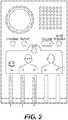
- FIG. 2shows an embodiment of a receiver unit.
- the receiver unitis placed in proximity to the patient, in order to receive the signal transmitted by a wireless sensor being used on the patient.
- the receiver unitis located at the bedside of the patient.
- the receiver unitis worn by the patient, for example when the patient is being transported.
- the receiver unitis associated with a single wireless sensor being used on a patient.
- the receiver unitis associated with multiple wireless sensors. For example, as shown in FIG. 2 , a single receiver unit can monitor wireless sensors placed on multiple locations on a patient, such as over each lung on the chest or back, as well as an additional wireless sensor on a handheld sensor holder.
- the receiver unitfurther comprises a filtering and/or amplifying means for separating cardiac sounds from pulmonary sounds when the wireless sensor transmits both the pulmonary sounds and the cardiac sounds to the receiver unit.
- the receiver unitcomprises a speaker for listening to the pulmonary, cardiac or digestive sounds of the patient.
- the receiver unitcomprises, for example, volume controls, a control for muting the speaker, controls for selecting the wireless sensor being monitored by the receiver unit, controls and contacts, such as a dedicated slot, for programming the association of a wireless sensor with the receiver unit and a place to store a handheld sensor holder unit comprising a wireless sensor associated with the receiver unit.
- the receiver unitcomprises a headphone jack so that the practitioner can more closely/clearly hear the pulmonary, cardiac or digestive noises being monitored.
- the receiver unitcan replay a segment of the monitored noises so that the practitioner can further analyze a noise or event.
- the receiver unitcan replay about the previous 30 seconds of monitored sounds.
- the receiver unitcan replay about the previous 20 seconds of monitored sounds.
- the receiver unitcan replay about the previous 15 seconds of monitored sounds.
- the receiver unitcan replay about the previous 10 seconds of monitored sounds.
- FIG. 3depicts an exemplary programming of wireless sensors to be associated with a particular receive unit.
- a packaged sterile wireless sensor contained in a disposable pad( FIG. 3A ) is contacted with a dedicated slot on a receiver unit ( FIG. 3B ).
- the disposable pad comprising a wireless sensoris then removed from the package ( FIG. 3C ) and placed either in a handheld sensor holder ( FIG. 3D ) or on the corresponding location ( FIG. 2 ) on the patient's body, as depicted in FIG. 1 .
- the wireless sensorcan either be discarded with the disposable pad, or removed from the disposable pad ( FIG. 3E ), sterilized and/or refurbished and installed into a new, sterile disposable pad for future reuse.
- FIG. 4depicts another exemplary receiver unit comprising volume controls, a control for muting the speaker, controls for selecting the wireless sensor being monitored by the receiver unit, controls for programming the association of a wireless sensor with the receiver unit and a place to store a handheld sensor holder unit comprising a wireless sensor associated with the receiver unit.
- the programming of wireless sensors to be associated with a particular receiver unitis done using a computer, or any other suitable input device, associated with the receiver unit.
- the receiver unitis further connected to a monitoring/transmitting unit.
- the connectionis a wireless connection.
- the connectionis a wired or cabled connection.
- the monitoring/transmitting unitis, or is further connected to, a computer.
- the monitoring/transmitting unitstores recorded transmissions, or portions thereof, in the medical records of the patient.
- the monitoring/transmitting unittransmits the bodily sounds detected by the wireless sensor to a user-end listening/displaying device, as shown in FIG. 5 , such as, but not limited to, a cell phone, smart phone, PDA or tablet computer.
- the soundsare transmitted to the electronic device in real time.
- the soundsare transmitted to the electronic device in a delayed transmission.
- the soundsare transmitted to the electronic device as a recording.
- the receiving unitis an electronic device, as shown in FIG. 5 , such as, but not limited to, a cell phone, smart phone, PDA or tablet computer.
- the electronic devicecomprises a dedicated software application that allows the health practitioner to, for example, hear the real time bodily sounds transmitted from a patient, delayed bodily sounds transmitted from a patient or previously recorded bodily sounds transmitted from a patient.
- the applicationprovides a visual output representing the real time, delayed, and/or recorded bodily sounds transmitted from a patient.
- the applicationallows the health practitioner to compare the real time or delayed bodily sounds transmitted from a patient to the delayed or recorded bodily sounds transmitted from said patient.
- the applicationprocesses the bodily sounds transmitted from a patient and provides the health practitioner with a preliminary diagnosis of the patient's condition.
- the applicationcomprises functionality that allows the health practitioner to listen to, and switch between the bodily sounds from multiple patients.
- the applicationcomprises a database of reference sounds that allow the health practitioner to listen to, or see a graphic representation of, an exemplary or representative sound associated with a particular condition.
- the monitoring/transmitting unittransmits the pulmonary, cardiac or digestive sounds detected by the wireless sensor to an electronic device in an audible format. In other embodiments, the monitoring/transmitting unit transmits the pulmonary, cardiac or digestive sounds detected by the wireless sensor to an electronic device as a graphic representation, such as shown in FIG. 5 . In still other embodiments, the monitoring/transmitting unit transmits the pulmonary, cardiac or digestive sounds detected by the wireless sensor to an electronic device both in an audible format and as a graphic representation.
- the receiver unitfurther comprises software that is capable of analyzing the received sound signal and provide a prognosis based on the result of the analysis.
- the receiver unittransmits the sound file received from the sensor to a computer having software that is capable of analyzing the received sound signal and provide a prognosis based on the result of the analysis.
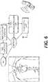
- FIG. 6shows an embodiment of the device wherein the wireless sensor comprises at least one microphone, at least one preamplifier for cardiac and/or pulmonary sounds, at least one filter unit for removing background noises, at least one power amplifier unit for enhancing auscultation sounds of the desired wavelengths, at least one microcontroller unit for processing and enhancing the sounds to be transmitted and at least one transmission unit that sends the desired sounds wirelessly to a receiver unit.
- the wireless sensorfurther comprises a battery or other power source for powering the microphone(s), preamplifier(s), filter(s), power amplifier(s), microcontroller(s) and transmission unit(s).
- the microphonepicks up as many bodily sounds as possible and the filter unit is programmed to allow the further transmission of only the bodily sounds that occur within the range of wavelengths of interest.
- the wireless sensortransmits signal directly to a user-end listening or displaying device. In other embodiments, the wireless sensor transmits signal first to a receiver unit. The receiver unit then transmits the signal to a user-end listening or displaying device. In yet other embodiments, the wireless sensor transmits signal first to a receiver unit. The receiver unit transmits the signal to a monitoring/transmitting unit, which then transmits the signal to a user-end listening or displaying device. In the above-described embodiments, the signals may be filtered and/or amplified by the wireless sensor, the receiver unit, the monitoring/transmitting unit, or combinations thereof.
- the present devicecomprises wireless connectivity of a monitoring/transmitting unit to a base station.
- the wireless connectivityis via Bluetooth.
- the base stationcan be a cell phone, smart phone, PDA or a tablet computer.
- the smart phone or tabletcomprises an installed custom application that will depict the data transferred through the data acquisition device with the ability to review and compare previously recorded data from the patient.
- the sensor or microphonewould detect heart, lung or digestive sounds which would be pre-amplified and filtered for noise and unwanted frequencies prior to digitization.
- the microphonewould be interfaced to a Analog to Digital Converter (ADC) microcontroller to convert the auscultation sounds to a digital form for transmission.
- ADCAnalog to Digital Converter
- Filtered datacould be converted digitally from the microphone by the microcontroller for onward transmission through, for example, a Bluetooth Module in Slave Mode for display and storage.
- the wireless moduleis a battery operated system.
- the battery operated systemcomprises an intelligent power management (IPM) system.
- IPMintelligent power management
- power managementis programmable.
- the batteryis rechargable.
- the present applicationis further illustrated by the following examples which should not be construed as limiting.
- the present applicationdescribes a device with multiple components that have been individually described. It is conceived that these multiple components can be interchanged with one another in any manner that can be imagined by one of skill in the art for the operation of the described wireless stethoscope system.
- the order in which various components have been described in the present applicationis not limiting upon the ability to combine said components with one another.
- Disposable tabscomprising wireless sensors are programmed with a receiver unit and placed on the patient's chest and back in the corresponding locations.
- the pulmonary sounds that have been detected by the wireless sensorsare analyzed by the attending physician.
- the attending physicianconsults with a pulmonary specialist in a remote location and transmits audio and graphic representations of the patient's pulmonary sounds to the pulmonary specialist.
- the attending physician and the pulmonary specialistdetermine a proper therapeutic course for the patient.
Landscapes
- Health & Medical Sciences (AREA)
- Life Sciences & Earth Sciences (AREA)
- Engineering & Computer Science (AREA)
- Physics & Mathematics (AREA)
- Molecular Biology (AREA)
- Medical Informatics (AREA)
- Veterinary Medicine (AREA)
- Public Health (AREA)
- General Health & Medical Sciences (AREA)
- Animal Behavior & Ethology (AREA)
- Surgery (AREA)
- Biomedical Technology (AREA)
- Heart & Thoracic Surgery (AREA)
- Pathology (AREA)
- Biophysics (AREA)
- Physiology (AREA)
- Acoustics & Sound (AREA)
- Cardiology (AREA)
- Signal Processing (AREA)
- Computer Networks & Wireless Communication (AREA)
- Pulmonology (AREA)
- Psychiatry (AREA)
- Computer Vision & Pattern Recognition (AREA)
- Artificial Intelligence (AREA)
- Multimedia (AREA)
- Measuring And Recording Apparatus For Diagnosis (AREA)
- Measuring Pulse, Heart Rate, Blood Pressure Or Blood Flow (AREA)
- Measurement Of The Respiration, Hearing Ability, Form, And Blood Characteristics Of Living Organisms (AREA)
Description
- This application generally relates to medical devices. In particular, the application relates to wireless stethoscopes.
- Annually, more than one million people contract infections in a hospital while they are being treated for some other disease or condition. One common cause of transfer of infections between patients is the stethoscope. The stethoscope is used on nearly all patients to monitor cardiac, pulmonary or digestive sounds, but is rarely washed between patients. One study sampling 150 stethoscopes found that 133 of them (88%) harboredStaphylococcus bacteria. Infections, including nosocomial infections, which are those that are contracted in a medical facility, cost taxpayers over 25 billion dollars annually. While increased washing of stethoscopes or the use of barrier devices, such as plastic sleeves, may reduce nosocomial infections, these options are often not practical in fast-paced medical environments.
- As the shortage of medical professionals persists , there exists a need for a stethoscope that will allow for a physician to simultaneously monitor multiple patients. Documents
WO2008/097008 A1 andUS2007/0106179 A1 disclose prior art wireless auscultation systems comprising a wireless sensor for detecting bodily sounds and for transmitting said sound signals to a receiver interfaced with a user-end device. - Additionally, conventional stethoscopes cannot separate the sounds from one bodily function from another and require the practitioner to listen for pulmonary, cardiac or digestive sounds while the other sounds are also present, and sometimes louder than the sound of interest. While simple non-invasive cardiac function can be monitored by taking a patient's pulse or measuring blood pressure, simple non-invasive pulmonary function can only be adequately determined by directly listening to the lungs with a stethoscope. Placing a hand over the patient's mouth or listening to breath from the mouth and nose do not provide adequate insight into lung function. Furthermore, cardiac and pulmonary sounds tend to be in the same frequency, so pulmonary sounds, particularly weak pulmonary sounds, can be difficult to discern.
- Accordingly, there exists a need in the art for a stethoscope device that is useable on a single patient and is disposable in order to prevent transmission of infectious organisms by conventional stethoscopes and for a device that can filter cardiac, pulmonary and digestive sounds, allowing the practitioner to listen to, and focus on, only one type of bodily sound.
- The present invention is defined by a wireless stethoscope according to claim 1.
- The present invention is also defined by a method for monitoring at least one bodily sound of a patient according to claim 12.
- Preferred embodiments are defined in the dependent claims.
FIG. 1 shows exemplary placement of disposable sensors over the lungs of a patient.FIG. 2 shows an exemplary receiver unit of the device along with a handheld sensor holder unit, further having ports for the programming of individual sensors.FIGS. 3A-E show an exemplary schematic showing components of the device and their deployment.FIG. 4 shows another exemplary receiver unit of the device along with a handheld sensor holder unit.FIG. 5 shows an exemplary graphic of the monitoring of a bodily sound as transmitted to a remote device.FIG. 6 shows a schematic for an embodiment of the device that can transmit directly to a wirelessly linked listening device.- The following detailed description is presented to enable any person skilled in the art to make and use the invention. For purposes of explanation, specific nomenclature is set forth to provide a thorough understanding of the present invention. However, it will be apparent to one skilled in the art that these specific details are not required to practice the invention. Descriptions of specific applications are provided only as representative examples. The present invention is not intended to be limited to the embodiments shown. Instead, the scope of the invention is defined by the appended claims.
- One aspect of the present invention relates to a wireless stethoscope according to claim 1. The wireless stethoscope comprises at least one wireless sensor for monitoring at least one bodily sound and a receiver unit, wherein the wireless sensor detects one or more bodily sounds, converts the one or more bodily sounds into sound signals, and transmits the sound signals wirelessly to the receiver unit, wherein the receiver receives and processes the sound signals and transmits the sound signals to a user-end listening and displaying device.
- In some embodiments, the wireless sensor is enclosed in or attaches to a disposable pad.
- The wireless sensor comprises at least one microphone that detects bodily sounds.
- In other embodiments, the wireless stethoscope comprises more than one wireless sensor programmed to the receiver unit.
- In other embodiments, the wireless sensor comprises a rechargeable battery.
- In other embodiments, the bodily sound is selected from the group consisting of a pulmonary sound, a cardiac sound, and a digestive sound.
- In other embodiments, the receiver unit is an electronic device selected from the group consisting of a cell phone, smart phone, PDA and tablet computer. In other embodiments, the electronic device comprises an application for monitoring said at least one bodily sound.
- The wireless sensor comprises a preamplifier that amplifies bodily sounds within a specific wavelength range, wherein the specific wavelength range corresponds to the wavelength of sounds typical of pulmonary sounds or the wavelength of sounds typical of cardiac sounds.
- The wireless sensor further comprises a filter circuit that removes or reduces bodily noises that are outside a specific wavelength range. The filter circuit is further capable of distinguishing and separating cardiac sounds from pulmonary sounds, such that only the pulmonary sounds or the cardiac sounds are transmitted to the receiver. In some embodiments, the filter circuit further removes or reduces background noises selected from the group consisting of ambient noises, voices, and metallic sounds. The filter circuit is further interfaced with a power amplifier that amplifies bodily sounds that are within the specific wavelength range.
- The wireless sensor also comprises an analog to digital converter interfaced to a microcontroller that digitizes bodily sounds that are within the specific wavelength range, and a transmitter unit for wireless transmission of digitized bodily sounds within a specific wavelength range to the receiver unit. In some embodiments, the wireless transmission is selected from the group consisting of radio frequency communication signals, infrared communication signals, short-wavelength radio transmissions and IEEE 802.15.1 signals.
- In some embodiments, the receiver unit is interfaced with the central transmitting unit and further transmits the at least one bodily sound to the central transmitting unit. In some embodiments, the interface between said receiver unit and said central transmitting unit is wired or wireless.
- In some embodiments, the central transmitting unit is interfaced with more than one receiver unit.
- In other embodiments, the central transmitting unit is further interfaced with at least one storage device. In some embodiments, the at least one bodily sound is recorded on the at least one storage device.
- In other embodiments, the central transmitting unit is further interfaced with at least one listening device. In some embodiments, the at least one listening device is an electronic device selected from the group consisting of a cell phone, smart phone, PDA, tablet computer and combinations thereof. In some embodiments, the central transmitting unit or said at least one listening device comprises an application that allows a practitioner to monitor at least one bodily sound from more than one patient. In some embodiments, the application analyzes the at least one bodily sound and provides or suggests a preliminary diagnosis based upon the at least one bodily sound.
- Another aspect of the present application relates to a method for monitoring at least one bodily sound of a patient, as outlined in Claim 12.
- In some embodiments, the central transmitting unit transmits the bodily sound to an additional listening device. In some embodiments, the additional listening device is selected from the group consisting of cell phones, smart phones, PDAs and tablet computers. The wireless sensor amplifies detected bodily sound and filters amplified sound to reduce background noise. In other embodiments, the receiver unit filters received bodily sound to reduce back ground noise prior to transmission.
- The wireless sensor comprises at least a detection device that is capable of detecting normal and abnormal bodily sounds, such as normal and abnormal pulmonary sounds, cardiac sounds, digestive sounds, and other bodily sounds. Examples of pulmonary sounds include, but are not limited to, breathing sounds, bronchial sounds, bronchovesicular sounds and vesicular sounds. Examples of abnormal breathing sounds include, but are not limited to, crackles, wheezes, rales, ronchi, stridor and stertor. Examples of abnormal cardiac sounds include, but are not limited to, murmurs such as systolic murmurs and diastolic murmurs, abnormal sinus rhythm. Examples of digestive sounds include, but are not limited to, stomach growls, bowel sounds, and borborygmus.
- The wireless sensor is capable of picking up a bodily sound, converting the sound into an electrical signal, and transmitting the electrical signal wirelessly to the receiver unit. In some embodiments, the wireless sensor comprises a microphone comprising a transducer that converts a sound into an electrical signal, a printed circuit board (PCB) that processes the electrical signal, and a transmitter that transmits the processed electrical signal wirelessly to the receiver unit.
- The microphone can be any microphone suitable to be fitted into a wireless sensor and to pick up a bodily sound. In some embodiments, the microphone is optimized to detect pulmonary sounds. In one embodiment, the microphone is an unidirectional microphone that is sensitive to sounds from only one direction. In other embodiments, the microphone is optimized to detect sound in the frequency range of 20 to 3000 Hz, 20 to 2500 Hz, 20 to 2000 Hz, 20 to 1800 Hz, 20 to 1500 Hz, 20 to 1200 Hz, 20 to 1000 Hz or 20 to 800 Hz
- In some embodiments, the microphone is a contact microphone that picks up vibrations directly from a solid surface or object, as opposed to sound vibrations carried through air. In one embodiment, the contact microphone comprises a magnetic (moving coil) transducer, contact plate, and contact pin. The contact plate is placed directly on to a body surface, and the contact pin transfers vibrations to the coil.
- In some embodiments, the PCB comprises a sound filter circuit that removes or reduces background noise. As used herein, the term "background noise" refers to any noise that is not intended to be captured and transmitted to the receiver unit for monitoring bodily sounds of interest from the subject. For example, background noises include, but are not limited to, ambient sounds, voices, and metallic sounds. The sound filter circuit is capable of distinguishing cardiac sounds from pulmonary sounds or digestive sounds. In particular, the PCB comprises a filtering circuit for separating cardiac sounds from pulmonary sounds and/or digestive sounds and transmitting only the pulmonary sounds or the cardiac sounds to the receiver. The PCB further comprises an amplification circuit that amplifies the filtered sounds for transmission. In some other embodiments, the PCB comprises an amplification circuit that selective amplifies the cardiac sounds, the pulmonary sounds, or both cardiac sounds and pulmonary sounds. The sounds detected by the microphone are amplified first and then filtered to reduce noise and unwanted frequencies and then amplified again. The amplified and filtered sound signals are then digitized for transmission.
- The transmitter is capable of transmitting signals wirelessly. In one embodiment, the transmitter transmits signals via radio frequency communication (e.g., a FM radio transmitter). In another embodiment, the transmitter transmits signals via microwave communication. In another embodiment, the transmitter transmits signals via infrared (IR) communication. In some embodiments, the transmitter is a short range transmitter with a maximum transmission range of 50, 25, 10 or 5 feet in order to prevent interference between the signals of wireless stethoscopes used on different patients. In a particular embodiment, the maximum transmission range of the wireless sensor is about 50 feet. In another embodiment, the maximum transmission range of the wireless sensor is about 25 feet. In another embodiment, the maximum transmission range of the wireless sensor is about 10 feet. In yet another embodiment, the maximum transmission range of the wireless sensor is about 5 feet.
- In some embodiments, the wireless sensor is capable of converting a detected sound into an electronic sound file and transmitting the sound file instantaneously or within 5, 4, 3, 2 or 1 second from the time of detection.
- In other embodiments, the wireless sensor comprise two or more microphones that are capable of picking up different types of bodily sounds. In one embodiment, the wireless sensor comprise two microphones, one is optimized for detecting pulmonary sounds and the other one is optimized for picking up cardiac sounds. In another embodiments, the wireless sensor comprise three microphones, one is optimized for detecting pulmonary sounds, the other one is optimized for detecting cardiac sounds, while the third one is optimized for detecting digestive sounds.
- In some embodiments, the wireless sensor is programmable wirelessly through the receiver unit. Examples of the programmable features include, but are not limited to, optimized sounds detection (e.g., pulmonary sounds only, cardiac sounds only, digestive sounds only, or combinations of thereof), transmission range, transmission duration (e.g., 30, 60, 90 or 120 seconds), transmission interval (e.g., every 30, 60, 90 or 120 minutes). In other embodiments, the wireless sensor transmits signal with a unique electronic signature or unique transmission channel so that multiple wireless sensors may be used on a single patient (e.g., at different locations on the patient body) or on different patients (e.g., one or two sensors on each patients) with a single receiver unit. The receiver unit will be able to identify each of the multiple sensors attached to the same patient or each of the multiple sensors attached to different patients based on the unique electronic signature or unique transmission channel of each sensor.
- In other embodiments, the wireless sensor further comprises a battery. In a further embodiment, the battery is rechargeable. In another further embodiment, the battery is non-rechargeable. In some embodiments, the wireless sensor has an on/off switch to preserve battery life when the monitor is not in use. In some embodiments, the on/off switch is manually toggled on the wireless sensor. In some embodiments, the on/off switch on the wireless sensor is remotely toggled from a control on the receiver unit or another device. In some embodiments, the wireless sensor is equipped with an Intelligent Power Management system and contains a circuitry that automatically turns off the sensor under pre-set conditions. For example, the on/off switch on the wireless sensor toggles may be automatic when the receiver unit is turned on or off. In some embodiments, there is a removable tab interrupting the current flow from the battery prior to use of the wireless sensor and said tab is removed when the wireless sensor is first used on a patient.
- The wireless sensor of the present application is sized for easy attachment to a body part. The wireless sensor can be of any shape or color. In some embodiments, the wireless sensor has a diameter of 5, 4, 3, 2 or 1 cm. In some embodiments, the wireless sensor is a light-weight sensor with a weight of less than 50, 40, 30, 20, 10 or 5 grams. In other embodiments, the wireless sensor is wrapped in a disposable pad. In some embodiments, the disposable pad contains an adhesive to attach the wireless sensor to the body of a patient. In some embodiments, the wireless sensor is a light-weight, short range sensor that has a weight of less than 50, 40, 30, 20, 10 or 5 grams and a transmission range of less than 15.24, 7.62, 3.05, 1.524 meter (50, 25, 10 or 5 feet).
- In some embodiments, the wireless sensor comprises a disposable pad or cover that is discarded after each use. In other embodiments, the wireless sensor is mountable to a handheld sensor holder.
- The receiver unit is capable of receiving a wireless signal from one or more wireless sensors. In some embodiments, the receiver unit receives radio frequency communication signals (e.g., a FM radio signals) from the wireless sensor. In other embodiments, the receiver unit receives microwave or infrared (IR) communication signals from the wireless sensor. In still other embodiments, the receiver unit receives short-wavelength radio transmissions, for example in the ISM band from 2400-2480 MHz (IEEE 802.15.1, or Bluetooth).
- In some embodiments, the receiver comprises a filter circuit that reduces the back ground noise in the signals received from the wireless sensor. In some embodiments, the receiver comprises an amplifying circuit and/or an amplifier. In other embodiments, the receiver comprises one or more circuits that filters for, and/or amplifies, desired sounds, such as pulmonary sounds, cardiac sounds, digestive sounds, or combinations thereof.
- The receiver can be a single channel receiver or multichannel receiver. In some embodiments, the receiver is a single channel receiver. In other embodiments, the receiver is a multi-channel receiver that is capable of receiving wireless transmissions from a plurality of wireless sensors. In some embodiments, the receiver is a multi-channel receiver that is capable of programing and/or receiving wireless transmissions from up to 2, 3, 4, 5, 6, 7, 8, 9 and 10 wireless sensors. In some embodiments, the receiver is programmable to designate the multiple channels to two or more patients in a setting where multiple patients are located in the same room. In other embodiments, the receiver is programmable to receiver and/or process only the signals from designated wireless sensors so that two or more receivers can be placed in the same room or in the proximity of each other without interfering with each other.
- In some embodiments, the receiver comprises a speaker such that a healthcare professional may listen to the bodily sound transmitted from the wireless sensor. In a related embodiment, the receiver comprises a volume control with or without a mute function. In other embodiments, the receiver does not contain a speaker but can be connected to a speaker to play the sound received from the wireless sensor. In other embodiments, the receiver further comprises a graphic display that is capable of displaying sound waves or sound profiles. In other embodiments, the receiver is a smart phone or tablet.
- In some embodiments, the receiver comprises a memory or record means that is capable of storing sound signals received from the wireless sensor. In one embodiment, the receiver stores sound signals received from the last 180, 120, 90, 60, 30 or 10 seconds.
- In some embodiments, the receiver is powered by 110 v or 220 v AC power. In other embodiments, the receiver unit is battery powered or comprises a battery back-up. In another embodiment, the wireless sensor further comprises a battery. The battery may be a rechargeable or non-rechargeable battery. In some embodiments, the wireless sensor has an on/off switch to preserve battery life when the monitor is not in use.
- In certain embodiments, the receiver further comprises a transmitting unit that is capable of further transmitting the sound files to a user-end unit, such as a central monitoring and/or transmitting unit located at a convenient location such as a nurse station, or a hand-held listening device. The central monitoring/transmitting unit can interface or communicate with multiple receiver units that are each dedicated to wireless sensors attached to different individual patients. The central monitoring/transmitting unit can be interfaced with said multiple receiver units by wired or wireless means or a combination thereof. The central monitoring/transmitting unit can be further interfaced with a computer and/or storage device for processing sounds from the individual patients and/or storing the transmitted bodily sounds from individual patients into a medical record. The central transmitting unit can also interface with the listening device of one or more health practitioners. In some embodiments, the listening device is an electronic device such as, but not limited to, a cell phone, smart phone, PDA or tablet computer. In some embodiments, the central monitoring/transmitting unit is capable of analyzing sounds received from individual patient and providing analysis results that may facilitate diagnosis of the patient.
- In some embodiments, the receiver unit simply transmits all the received sounds to the central monitoring/transmitting unit. In other embodiments, the receiver unit filters the received sounds to reduce background noise and/or unwanted frequencies, and transmits the filtered sounds to the central monitoring unit. In other embodiments, the receiver unit amplifies the detected sounds and transmits the amplified sounds to the central monitoring/transmitting unit. In yet other embodiments, the receiver unit amplifies and filters the detected sounds and transmits the amplified and filtered sounds to the central monitoring/transmitting unit.
- In some embodiments, the receiver unit, the central monitoring/transmitting unit and/or the end listening devices (such as cell phone, smart phone, PDA or tablet computer) comprises a dedicated software application that allows the health practitioner to, for example, hear the real time bodily sounds transmitted from a patient, delayed bodily sounds transmitted from a patient or previously recorded bodily sounds transmitted from a patient. In some embodiments, the software application provides a visual output representing the real time, delayed, and/or recorded bodily sounds transmitted from a patient. In some embodiments, the software application allows the health practitioner to compare the real time or delayed bodily sounds transmitted from a patient to the delayed or recorded bodily sounds transmitted from said patient. In some embodiments, the software application processes the bodily sounds transmitted from a patient and provides the health practitioner with a preliminary diagnosis of the patient's condition.
- Another aspect of the present application relates to a method for monitoring bodily sounds of a patient comprising: programming at least one wireless sensor of a wireless stethoscope to transmit to a receiver unit, contacting said wireless sensor with the body of the patient, and monitoring the bodily sounds detected by the wireless sensor. In a particular embodiment, the bodily sounds are pulmonary sounds. In another particular embodiment, the bodily sounds are cardiac sounds. In another particular embodiment, the bodily sounds are digestive sounds.
- In another particular embodiment, the wireless sensor is comprised in a disposable pad. In a further embodiment, the disposable pad is adhered to a single location on the skin of the patient. In another further embodiment, the disposable pad is contained in a handheld sensor holder unit that is movable on the body of the patient.
FIG. 1 shows an embodiment of a wireless sensor. In this embodiment, the wireless sensor is enclosed in a disposable pad that makes direct contact with the skin of the patient. Also in this embodiment, the disposable pad has an adhesive surface that is applied to the skin of the patient. In this case, the disposable pad comprising the wireless sensor can remain on the same location of patient during the entire time that monitoring is required, such as during a hospital stay. In other embodiments, the wireless sensor is mounted on a handheld sensor holder as shown, for example, inFIG. 3D . The handheld handle can be used in the same manner as a conventional stethoscope, being moved around to different locations on the patient's body.- In either case, when there is no longer a need to monitor the bodily sounds of said patient, the disposable pad is discarded. In some embodiments, for example, as shown in
FIG. 3E , the wireless sensor is removed from the disposable pad prior to discarding the disposable pad. In some embodiments, the wireless sensor is then sterilized and inserted into a new disposable pad. FIG. 2 shows an embodiment of a receiver unit. The receiver unit is placed in proximity to the patient, in order to receive the signal transmitted by a wireless sensor being used on the patient. In some embodiments, the receiver unit is located at the bedside of the patient. In other embodiments, the receiver unit is worn by the patient, for example when the patient is being transported.- In particular embodiments, the receiver unit is associated with a single wireless sensor being used on a patient. In other embodiments, the receiver unit is associated with multiple wireless sensors. For example, as shown in
FIG. 2 , a single receiver unit can monitor wireless sensors placed on multiple locations on a patient, such as over each lung on the chest or back, as well as an additional wireless sensor on a handheld sensor holder. - In some embodiments, the receiver unit further comprises a filtering and/or amplifying means for separating cardiac sounds from pulmonary sounds when the wireless sensor transmits both the pulmonary sounds and the cardiac sounds to the receiver unit.
- In particular embodiments, as shown in
FIG. 2 , the receiver unit comprises a speaker for listening to the pulmonary, cardiac or digestive sounds of the patient. In some embodiments, the receiver unit comprises, for example, volume controls, a control for muting the speaker, controls for selecting the wireless sensor being monitored by the receiver unit, controls and contacts, such as a dedicated slot, for programming the association of a wireless sensor with the receiver unit and a place to store a handheld sensor holder unit comprising a wireless sensor associated with the receiver unit. - In some embodiments, the receiver unit comprises a headphone jack so that the practitioner can more closely/clearly hear the pulmonary, cardiac or digestive noises being monitored. In some embodiments, the receiver unit can replay a segment of the monitored noises so that the practitioner can further analyze a noise or event. In a particular embodiment, the receiver unit can replay about the previous 30 seconds of monitored sounds. In another particular embodiment, the receiver unit can replay about the previous 20 seconds of monitored sounds. In still another particular embodiment, the receiver unit can replay about the previous 15 seconds of monitored sounds. In yet another particular embodiment, the receiver unit can replay about the previous 10 seconds of monitored sounds.
FIG. 3 depicts an exemplary programming of wireless sensors to be associated with a particular receive unit. A packaged sterile wireless sensor contained in a disposable pad (FIG. 3A ) is contacted with a dedicated slot on a receiver unit (FIG. 3B ). The disposable pad comprising a wireless sensor is then removed from the package (FIG. 3C ) and placed either in a handheld sensor holder (FIG. 3D ) or on the corresponding location (FIG. 2 ) on the patient's body, as depicted inFIG. 1 . When a wireless sensor is no longer needed on the patient, the
wireless sensor can either be discarded with the disposable pad, or removed from the disposable pad (FIG. 3E ), sterilized and/or refurbished and installed into a new, sterile disposable pad for future reuse.FIG. 4 depicts another exemplary receiver unit comprising volume controls, a control for muting the speaker, controls for selecting the wireless sensor being monitored by the receiver unit, controls for programming the association of a wireless sensor with the receiver unit and a place to store a handheld sensor holder unit comprising a wireless sensor associated with the receiver unit. In some embodiments, the programming of wireless sensors to be associated with a particular receiver unit is done using a computer, or any other suitable input device, associated with the receiver unit.- In some embodiments, the receiver unit is further connected to a monitoring/transmitting unit. In some embodiments, the connection is a wireless connection. In some embodiments, the connection is a wired or cabled connection. In some embodiments, the monitoring/transmitting unit is, or is further connected to, a computer.
- In some embodiments, the monitoring/transmitting unit stores recorded transmissions, or portions thereof, in the medical records of the patient.
- In some embodiments, the monitoring/transmitting unit transmits the bodily sounds detected by the wireless sensor to a user-end listening/displaying device, as shown in
FIG. 5 , such as, but not limited to, a cell phone, smart phone, PDA or tablet computer. In some embodiments, the sounds are transmitted to the electronic device in real time. In other embodiments, the sounds are transmitted to the electronic device in a delayed transmission. In still other embodiments, the sounds are transmitted to the electronic device as a recording. - In some embodiments, the receiving unit is an electronic device, as shown in
FIG. 5 , such as, but not limited to, a cell phone, smart phone, PDA or tablet computer. In some embodiments, the electronic device comprises a dedicated software application that allows the health practitioner to, for example, hear the real time bodily sounds transmitted from a patient, delayed bodily sounds transmitted from a patient or previously recorded bodily sounds transmitted from a patient. In some embodiments, the application provides a visual output representing the real time, delayed, and/or recorded bodily sounds transmitted from a patient. In some embodiments, the application allows the health practitioner to compare the real time or delayed bodily sounds transmitted from a patient to the delayed or recorded bodily sounds transmitted from said patient. In some embodiments, the application processes the bodily sounds transmitted from a patient and provides the health practitioner with a preliminary diagnosis of the patient's condition. In other embodiments, the application comprises functionality that allows the health practitioner to listen to, and switch between the bodily sounds from multiple patients. In some embodiments, the application comprises a database of reference sounds that allow the health practitioner to listen to, or see a graphic representation of, an exemplary or representative sound associated with a particular condition. - In some embodiments, the monitoring/transmitting unit transmits the pulmonary, cardiac or digestive sounds detected by the wireless sensor to an electronic device in an audible format. In other embodiments, the monitoring/transmitting unit transmits the pulmonary, cardiac or digestive sounds detected by the wireless sensor to an electronic device as a graphic representation, such as shown in
FIG. 5 . In still other embodiments, the monitoring/transmitting unit transmits the pulmonary, cardiac or digestive sounds detected by the wireless sensor to an electronic device both in an audible format and as a graphic representation. - In some embodiments, the receiver unit further comprises software that is capable of analyzing the received sound signal and provide a prognosis based on the result of the analysis. In other embodiments, the receiver unit transmits the sound file received from the sensor to a computer having software that is capable of analyzing the received sound signal and provide a prognosis based on the result of the analysis.
FIG. 6 shows an embodiment of the device wherein the wireless sensor comprises at least one microphone, at least one preamplifier for cardiac and/or pulmonary sounds, at least one filter unit for removing background noises, at least one power amplifier unit for enhancing auscultation sounds of the desired wavelengths, at least one microcontroller unit for processing and enhancing the sounds to be transmitted and at least one transmission unit that sends the desired sounds wirelessly to a receiver unit. In some embodiments, the wireless sensor further comprises a battery or other power source for powering the microphone(s), preamplifier(s), filter(s), power amplifier(s), microcontroller(s) and transmission unit(s). In some embodiments, the microphone picks up as many bodily sounds as possible and the filter unit is programmed to allow the further transmission of only the bodily sounds that occur within the range of wavelengths of interest.- In some embodiments, the wireless sensor transmits signal directly to a user-end listening or displaying device. In other embodiments, the wireless sensor transmits signal first to a receiver unit. The receiver unit then transmits the signal to a user-end listening or displaying device. In yet other embodiments, the wireless sensor transmits signal first to a receiver unit. The receiver unit transmits the signal to a monitoring/transmitting unit, which then transmits the signal to a user-end listening or displaying device. In the above-described embodiments, the signals may be filtered and/or amplified by the wireless sensor, the receiver unit, the monitoring/transmitting unit, or combinations thereof.
- In the case user-end listening or displaying device, the present device comprises wireless connectivity of a monitoring/transmitting unit to a base station. In some embodiments, the wireless connectivity is via Bluetooth. The base station can be a cell phone, smart phone, PDA or a tablet computer. In some embodiments, the smart phone or tablet comprises an installed custom application that will depict the data transferred through the data acquisition device with the ability to review and compare previously recorded data from the patient. The sensor or microphone would detect heart, lung or digestive sounds which would be pre-amplified and filtered for noise and unwanted frequencies prior to digitization. In some embodiments, the microphone would be interfaced to a Analog to Digital Converter (ADC) microcontroller to convert the auscultation sounds to a digital form for transmission. Filtered data could be converted digitally from the microphone by the microcontroller for onward transmission through, for example, a Bluetooth Module in Slave Mode for display and storage. In some embodiments, the wireless module is a battery operated system. In some further embodiments, the battery operated system comprises an intelligent power management (IPM) system. In some embodiments power management is programmable. In some embodiments, the battery is rechargable.
- The present application is further illustrated by the following examples which should not be construed as limiting. The present application describes a device with multiple components that have been individually described. It is conceived that these multiple components can be interchanged with one another in any manner that can be imagined by one of skill in the art for the operation of the described wireless stethoscope system. The order in which various components have been described in the present application is not limiting upon the ability to combine said components with one another.
- A patient presents in the emergency room of a community hospital in pulmonary distress. Disposable tabs comprising wireless sensors are programmed with a receiver unit and placed on the patient's chest and back in the corresponding locations.
- The pulmonary sounds that have been detected by the wireless sensors are analyzed by the attending physician. The attending physician consults with a pulmonary specialist in a remote location and transmits audio and graphic representations of the patient's pulmonary sounds to the pulmonary specialist. The attending physician and the pulmonary specialist determine a proper therapeutic course for the patient.
- The above description is for the purpose of teaching the person of ordinary skill in the art how to practice the invention, and it is not intended to cover all its embodiments. The scope of the present invention is defined by the appended claims.
Claims (13)
- A wireless stethoscope comprising at least one wireless sensor for monitoring bodily sounds and a receiver unit,
wherein said wireless sensor comprises:at least one microphone that detects bodily sounds;a preamplifier that amplifies the bodily sounds within a specific wavelength range, wherein said specific wavelength range corresponds to the wavelength of sounds typical of pulmonary sounds or the wavelength of sounds typical of cardiac sounds;a filter circuit that removes or reduces bodily noises that are outside said specific wavelength range, wherein said filter circuit is interfaced with a power amplifier that amplifies bodily sounds that are within said specific wavelength range;an analog to digital converter interfaced to a microcontroller that digitizes the bodily sounds that are within said specific wavelength range,and a transmitter unit for wireless transmission of said digitized bodily sounds within said specific wavelength range to said receiver unit,wherein said receiver unit receives and processes said sound signals and transmits said sound signals to a user-end listening and displaying device,
and wherein said filter circuit further distinguishes and separates cardiac sounds from pulmonary sounds, such that only the pulmonary sounds or the cardiac sounds are transmitted to the receiver. - The wireless stethoscope of Claim 1, wherein said wireless sensor is enclosed in or attaches to a disposable pad.
- The wireless stethoscope of Claim 1, wherein said wireless stethoscope comprises more than one wireless sensor programmed to said receiver unit.
- The wireless stethoscope of Claim 1, wherein said user-end listening and displaying device is an electronic device selected from the group consisting of a cell phone, smart phone, PDA and tablet computer.
- The wireless stethoscope of Claim 1, wherein said filter circuit further removes or reduces background noises selected from the group consisting of ambient noises, voices and metallic sounds.
- The wireless stethoscope of Claim 1, wherein said wireless transmission by said transmitter unit is selected from the group consisting of radio frequency communication signals, infrared communication signals, short-wavelength radio transmissions and IEEE 802.15.1 signals.
- The wireless stethoscope of Claim 1, wherein said receiver unit is further interfaced with a central transmitting unit and further transmits said at least one bodily sound to said central transmitting unit.
- The wireless stethoscope of Claim 7, wherein said central transmitting unit is further interfaced with at least one storage device.
- The wireless stethoscope of Claim 7, wherein said central transmitting unit is further interfaced with at least one listening device.
- The wireless stethoscope of Claim 9, wherein said central transmitting unit or said at least one listening device comprises an application that allows a practitioner to monitor at least one bodily sound from more than one patient.
- The wireless stethoscope of Claim 10, wherein said application analyzes said at least one bodily sound and provides or suggests a preliminary diagnosis based upon said at least one bodily sound.
- A method for monitoring bodily sounds of a patient using the wireless stethoscope of Claim 1, comprising:contacting the wireless sensor with the body of said patient, detecting and wirelessly transmitting bodily sounds using the wireless sensor;receiving and processing said bodily sounds with the receiver unit in the vicinity of said patient; and transmitting with said receiver unit said bodily sounds to a user-end listening and displaying device, wherein said user-end listening and displaying device is selected from the group consisting of cell phones, smart phones, PDAs and tablet computers.
- The method of Claim 12, comprising filtering, with said receiver unit the received bodily sounds to reduce background noise prior to transmission.
Applications Claiming Priority (2)
| Application Number | Priority Date | Filing Date | Title |
|---|---|---|---|
| US201261668191P | 2012-07-05 | 2012-07-05 | |
| PCT/US2013/031462WO2014007857A1 (en) | 2012-07-05 | 2013-03-14 | Wireless stethoscope and method of use thereof |
Publications (3)
| Publication Number | Publication Date |
|---|---|
| EP2869770A1 EP2869770A1 (en) | 2015-05-13 |
| EP2869770A4 EP2869770A4 (en) | 2016-03-09 |
| EP2869770B1true EP2869770B1 (en) | 2019-01-16 |
Family
ID=49879055
Family Applications (1)
| Application Number | Title | Priority Date | Filing Date |
|---|---|---|---|
| EP13813201.4ANot-in-forceEP2869770B1 (en) | 2012-07-05 | 2013-03-14 | Wireless stethoscope and method of use thereof |
Country Status (8)
| Country | Link |
|---|---|
| US (8) | US8956305B2 (en) |
| EP (1) | EP2869770B1 (en) |
| JP (3) | JP2015525606A (en) |
| CN (2) | CN104661597A (en) |
| AU (1) | AU2013287260B2 (en) |
| HK (1) | HK1209009A1 (en) |
| SG (2) | SG10201708580RA (en) |
| WO (1) | WO2014007857A1 (en) |
Families Citing this family (31)
| Publication number | Priority date | Publication date | Assignee | Title |
|---|---|---|---|---|
| WO2014007857A1 (en)* | 2012-07-05 | 2014-01-09 | Pulmonary Apps, Llc | Wireless stethoscope and method of use thereof |
| US9042568B2 (en)* | 2012-12-11 | 2015-05-26 | Barry Poplaw | Portable smart stethoscope formed of smart mobile device and casing assembly |
| TWI533845B (en)* | 2013-03-15 | 2016-05-21 | 美思科技股份有限公司 | Wireless electronic stethoscope |
| US9526438B2 (en)* | 2013-04-26 | 2016-12-27 | University Of Hawaii | Microwave stethoscope for measuring cardio-pulmonary vital signs and lung water content |
| US9973847B2 (en) | 2014-01-10 | 2018-05-15 | Eko Devices, Inc. | Mobile device-based stethoscope system |
| CN104305961B (en)* | 2014-10-20 | 2017-09-22 | 清华大学 | Gurgling sound monitors identifying system |
| CN104352248A (en)* | 2014-11-13 | 2015-02-18 | 四川长虹电器股份有限公司 | Heart sound, lung sound and fetal heart sound acquisition and health management system and method |
| US10856806B2 (en) | 2015-02-12 | 2020-12-08 | University Of Hawaii | Lung water content measurement system and calibration method |
| CN105286910A (en)* | 2015-11-27 | 2016-02-03 | 山东中弘信息科技有限公司 | Intelligent stethoscope |
| CN106037790A (en)* | 2016-05-31 | 2016-10-26 | 成都天奥电子股份有限公司 | Wireless auscultation device |
| CN108209960A (en)* | 2016-12-21 | 2018-06-29 | 厦门信源环保科技有限公司 | The sensing device further and sensing system of instantaneous transmission internal organs message |
| CN106691498A (en)* | 2017-02-06 | 2017-05-24 | 宁波江丰生物信息技术有限公司 | Borborygmus processing system |
| CN118512200A (en)* | 2017-09-28 | 2024-08-20 | 聿信医疗科技股份有限公司 | Networked Electronic Stethoscope System |
| US11375976B2 (en) | 2017-11-03 | 2022-07-05 | John Jun Cai | Wireless stethoscope for transmitting, recording, storing and diagnostic capabilities including an earpiece |
| CN108417225A (en)* | 2018-02-11 | 2018-08-17 | 广州市碳码科技有限责任公司 | A kind of breath sound monitoring method, device, terminal and computer readable storage medium |
| WO2019223919A1 (en)* | 2018-05-24 | 2019-11-28 | Drägerwerk AG & Co. KGaA | Method for making a bluetooth pairing for a patient monitor system, and patient monitor system |
| JP7073914B2 (en)* | 2018-05-30 | 2022-05-24 | オムロンヘルスケア株式会社 | Wheezing detector and wheezing detection program |
| JP6600721B1 (en)* | 2018-08-15 | 2019-10-30 | Ami株式会社 | Biological sound data transmission device and transmission system |
| CN110236589B (en)* | 2019-06-03 | 2022-04-29 | 苏州美糯爱医疗科技有限公司 | Real-time heart-lung sound automatic separation method of electronic stethoscope |
| USD941468S1 (en) | 2019-09-23 | 2022-01-18 | Eko Devices, Inc. | Electronic stethoscope device |
| US10709353B1 (en) | 2019-10-21 | 2020-07-14 | Sonavi Labs, Inc. | Detecting a respiratory abnormality using a convolution, and applications thereof |
| US10750976B1 (en) | 2019-10-21 | 2020-08-25 | Sonavi Labs, Inc. | Digital stethoscope for counting coughs, and applications thereof |
| US12433506B2 (en) | 2019-10-21 | 2025-10-07 | Sonavi Labs, Inc. | Digital stethoscope for counting coughs, and applications thereof |
| US10716534B1 (en)* | 2019-10-21 | 2020-07-21 | Sonavi Labs, Inc. | Base station for a digital stethoscope, and applications thereof |
| US10702239B1 (en) | 2019-10-21 | 2020-07-07 | Sonavi Labs, Inc. | Predicting characteristics of a future respiratory event, and applications thereof |
| US10709414B1 (en) | 2019-10-21 | 2020-07-14 | Sonavi Labs, Inc. | Predicting a respiratory event based on trend information, and applications thereof |
| CN111407306A (en)* | 2020-03-25 | 2020-07-14 | 暨南大学 | Multi-pass differential breath sound intelligent wearable monitoring system based on mobile terminal |
| IT202000014188A1 (en) | 2020-06-15 | 2020-09-15 | Univ Degli Studi Di Modena E Reggio Emilia | CLINICAL TELE-AUSCULATION DEVICE OF BODY SOUNDS |
| US20210401395A1 (en)* | 2020-06-29 | 2021-12-30 | Rabiatu Kamara | Audible Handheld Stethoscope |
| US11796312B2 (en)* | 2021-09-22 | 2023-10-24 | Apple Inc. | Body volume/shape determination using handheld devices |
| KR20230077430A (en)* | 2021-11-25 | 2023-06-01 | 배상운 | Smart phone and method of discovering lung disease using smart phone |
Family Cites Families (40)
| Publication number | Priority date | Publication date | Assignee | Title |
|---|---|---|---|---|
| JPS5936309U (en)* | 1982-08-30 | 1984-03-07 | 立川 士郎 | Stethoscope |
| JPS5936309A (en) | 1983-07-20 | 1984-02-28 | Matsushita Electric Ind Co Ltd | Video tape recorder switching device |
| JPS60261439A (en)* | 1984-06-07 | 1985-12-24 | 株式会社 デイム | Stethoscopic apparatus |
| JPS61253046A (en) | 1985-05-02 | 1986-11-10 | ゼノベ−シヨン・インコ−ポレイテツド | Convertible electronic stethoscope |
| JPS62148653A (en)* | 1985-12-24 | 1987-07-02 | 福田 淳三郎 | Stethoscope |
| JP2661124B2 (en) | 1988-04-13 | 1997-10-08 | ソニー株式会社 | Stethoscope |
| JPH0614920A (en)* | 1992-07-01 | 1994-01-25 | Kunitaka Mizobe | Stethoscope |
| CA2198844C (en)* | 1994-08-30 | 2007-08-07 | Knud Erik Baekgaard | An electronic stethoscope |
| NO300250B1 (en)* | 1995-02-09 | 1997-04-28 | Meditron As | Apparatus for listening to body sounds |
| US20020085724A1 (en)* | 1997-02-06 | 2002-07-04 | James A. Grasfield | Stethoscope communication and remote diagnosis system |
| US6014432A (en) | 1998-05-19 | 2000-01-11 | Eastman Kodak Company | Home health care system |
| WO2002024074A1 (en)* | 2000-09-18 | 2002-03-28 | Cybercare Technologies, Inc. | A system and method for providing a packet-based electronic stethoscope |
| US20020124295A1 (en)* | 2000-10-30 | 2002-09-12 | Loel Fenwick | Clothing apparatus, carrier for a biophysical sensor, and patient alarm system |
| US7052466B2 (en) | 2001-04-11 | 2006-05-30 | Cardiac Pacemakers, Inc. | Apparatus and method for outputting heart sounds |
| US20040076303A1 (en) | 2002-09-30 | 2004-04-22 | Andrey Vyshedskly | Multimedia adapter to an acoustic stethoscope |
| GB2410147A (en)* | 2004-01-13 | 2005-07-20 | Health & Life Co Ltd | Electronic stethoscope with piezo-electrical film contact microphone |
| JP4759727B2 (en)* | 2004-03-19 | 2011-08-31 | 国立大学法人山口大学 | Digital auscultation analysis system |
| US7976480B2 (en)* | 2004-12-09 | 2011-07-12 | Motorola Solutions, Inc. | Wearable auscultation system and method |
| KR20050030934A (en) | 2005-03-08 | 2005-03-31 | 한찬희 | Wireless stethoscope |
| US8064610B2 (en)* | 2005-06-29 | 2011-11-22 | The General Electric Company | Ambient noise canceling physiological acoustic monitoring system and method |
| US8092396B2 (en)* | 2005-10-20 | 2012-01-10 | Merat Bagha | Electronic auscultation device |
| JP4848524B2 (en)* | 2005-10-21 | 2011-12-28 | 国立大学法人山口大学 | Auscultation heart sound signal processing method and auscultation apparatus |
| JP2007275324A (en)* | 2006-04-07 | 2007-10-25 | Iscg Kk | Multifunctional electronic stethoscope |
| US8323189B2 (en) | 2006-05-12 | 2012-12-04 | Bao Tran | Health monitoring appliance |
| WO2007149536A2 (en) | 2006-06-21 | 2007-12-27 | Joseph Habboushe | Electronic stethoscope apparatus |
| KR100789705B1 (en)* | 2007-02-05 | 2008-01-03 | 동진메디칼 주식회사 | Wireless Stethoscope System with Multifunction Digital Stethoscope |
| CN101951830B (en)* | 2007-12-20 | 2012-11-28 | 阿克瑞克公司 | An adhesive patch for monitoring acoustic signals |
| KR100918575B1 (en) | 2007-12-27 | 2009-09-24 | 마산대학산학협력단 | Multi-Bio Signal Wireless Monitoring System |
| CN101507613A (en)* | 2008-11-25 | 2009-08-19 | 余翔 | Intelligent multifunctional stethoscope |
| KR20100094042A (en) | 2009-02-18 | 2010-08-26 | 전북대학교산학협력단 | Apparatus for wireless sound transmission electronic stethoscope using separable auscultating chest piece |
| JP2013508130A (en) | 2009-10-14 | 2013-03-07 | ジ アドミニストレイターズ オブ ザ チューレン エデュケイショナル ファンド | New multifunctional materials used for in-situ remediation of chlorinated hydrocarbons |
| KR20100103331A (en) | 2009-10-20 | 2010-09-27 | 이병훈 | Wireless stethoscope |
| US8554517B2 (en)* | 2010-02-25 | 2013-10-08 | Sharp Laboratories Of America, Inc. | Physiological signal quality classification for ambulatory monitoring |
| CN102125441A (en)* | 2011-04-12 | 2011-07-20 | 西安交通大学 | Wireless stethoscope for preventing cross-contact |
| KR20110047181A (en)* | 2011-04-19 | 2011-05-06 | 문종섭 | Wireless Electronic Stethoscope Using Bluetooth Communication |
| CN202211702U (en)* | 2011-07-07 | 2012-05-09 | 深圳市资福技术有限公司 | Wireless stethoscope |
| WO2014007857A1 (en) | 2012-07-05 | 2014-01-09 | Pulmonary Apps, Llc | Wireless stethoscope and method of use thereof |
| CN103006256A (en)* | 2012-07-26 | 2013-04-03 | 黄涛生 | Medical electronic monitoring terminal equipment and transmission system |
| TWI533845B (en) | 2013-03-15 | 2016-05-21 | 美思科技股份有限公司 | Wireless electronic stethoscope |
| ES1079058Y (en) | 2013-04-08 | 2013-07-25 | Perez Ruben Lopez | WIRELESS ADJUSTMENT SYSTEM |
- 2013
- 2013-03-14WOPCT/US2013/031462patent/WO2014007857A1/enactiveApplication Filing
- 2013-03-14SGSG10201708580RApatent/SG10201708580RA/enunknown
- 2013-03-14HKHK15109417.9Apatent/HK1209009A1/enunknown
- 2013-03-14EPEP13813201.4Apatent/EP2869770B1/ennot_activeNot-in-force
- 2013-03-14CNCN201380035748.9Apatent/CN104661597A/enactivePending
- 2013-03-14USUS13/827,443patent/US8956305B2/enactiveActive
- 2013-03-14JPJP2015520164Apatent/JP2015525606A/enactivePending
- 2013-03-14SGSG11201500051PApatent/SG11201500051PA/enunknown
- 2013-03-14AUAU2013287260Apatent/AU2013287260B2/ennot_activeCeased
- 2013-03-14CNCN201611213753.6Apatent/CN106943157A/enactivePending
- 2014
- 2014-12-18USUS14/575,772patent/US9974515B2/enactiveActive
- 2017
- 2017-06-19JPJP2017119242Apatent/JP6535703B2/ennot_activeExpired - Fee Related
- 2018
- 2018-04-18USUS15/955,938patent/US10433812B2/ennot_activeExpired - Fee Related
- 2019
- 2019-04-05USUS16/375,885patent/US10925574B2/ennot_activeExpired - Fee Related
- 2019-04-23JPJP2019081463Apatent/JP2019162442A/enactivePending
- 2019-07-24USUS16/521,278patent/US10987082B2/ennot_activeExpired - Fee Related
- 2020
- 2020-09-23USUS17/029,091patent/US20210007705A1/ennot_activeAbandoned
- 2021
- 2021-03-03USUS17/249,492patent/US20210204903A1/ennot_activeAbandoned
- 2021-12-10USUS17/643,626patent/US20220096043A1/ennot_activeAbandoned
Also Published As
| Publication number | Publication date |
|---|---|
| US20190231300A1 (en) | 2019-08-01 |
| US20150105682A1 (en) | 2015-04-16 |
| US20220096043A1 (en) | 2022-03-31 |
| US9974515B2 (en) | 2018-05-22 |
| US10987082B2 (en) | 2021-04-27 |
| US20190365343A1 (en) | 2019-12-05 |
| US10433812B2 (en) | 2019-10-08 |
| US20140012149A1 (en) | 2014-01-09 |
| US20210204903A1 (en) | 2021-07-08 |
| JP2017205528A (en) | 2017-11-24 |
| EP2869770A1 (en) | 2015-05-13 |
| HK1209009A1 (en) | 2016-03-24 |
| US20210007705A1 (en) | 2021-01-14 |
| AU2013287260A1 (en) | 2015-01-29 |
| JP6535703B2 (en) | 2019-06-26 |
| US8956305B2 (en) | 2015-02-17 |
| EP2869770A4 (en) | 2016-03-09 |
| SG10201708580RA (en) | 2017-12-28 |
| US10925574B2 (en) | 2021-02-23 |
| CN104661597A (en) | 2015-05-27 |
| JP2019162442A (en) | 2019-09-26 |
| CN106943157A (en) | 2017-07-14 |
| SG11201500051PA (en) | 2015-03-30 |
| JP2015525606A (en) | 2015-09-07 |
| US20180279989A1 (en) | 2018-10-04 |
| AU2013287260B2 (en) | 2015-04-30 |
| WO2014007857A1 (en) | 2014-01-09 |
Similar Documents
| Publication | Publication Date | Title |
|---|---|---|
| US20220096043A1 (en) | Wireless stethoscope and method of use thereof | |
| TWI533845B (en) | Wireless electronic stethoscope | |
| US9566041B2 (en) | Adhesive patch having multiple acoustic sensors for monitoring acoustic signals | |
| US20040220487A1 (en) | Method and apparatus for physiological data acquisition via sound input port of computing device | |
| US20040220488A1 (en) | Method and apparatus for physiological data acquisition via sound input port of computing device | |
| US20090316925A1 (en) | Electronic stethoscope system | |
| CN102048587A (en) | Portable wireless electrocardiogram, cardiac sound and breath sound acquisition, display and storage device | |
| WO2011049293A1 (en) | Diagnosis-displaying wireless stethoscope | |
| CN107550515A (en) | Stethoscope system | |
| CN102048586A (en) | Portable wireless electrocardiogram, heart sound and breath sound acquisition terminal device | |
| US20140128755A1 (en) | Pulse Detecting Device and Method | |
| WO2015094426A1 (en) | A device for monitoring, recording and transmitting input received from a medical diagnostics instrument | |
| CN113520450B (en) | Wireless stethoscope | |
| CN210019399U (en) | Internal fistula blood vessel auscultation real-time monitoring device for hemodialysis patient | |
| HK1240480A1 (en) | Wireless stethoscope and method of use thereof | |
| CN212729836U (en) | Wireless stethoscope | |
| EP3793445B1 (en) | System for digitizing the sound of a stethoscope and for sending it to an electronic instrument | |
| CN213046974U (en) | Stethoscope | |
| CN213046975U (en) | Stethoscope | |
| Monisha et al. | A Review on Wireless Stethoscope |
Legal Events
| Date | Code | Title | Description |
|---|---|---|---|
| PUAI | Public reference made under article 153(3) epc to a published international application that has entered the european phase | Free format text:ORIGINAL CODE: 0009012 | |
| 17P | Request for examination filed | Effective date:20141230 | |
| AK | Designated contracting states | Kind code of ref document:A1 Designated state(s):AL AT BE BG CH CY CZ DE DK EE ES FI FR GB GR HR HU IE IS IT LI LT LU LV MC MK MT NL NO PL PT RO RS SE SI SK SM TR | |
| AX | Request for extension of the european patent | Extension state:BA ME | |
| DAX | Request for extension of the european patent (deleted) | ||
| RA4 | Supplementary search report drawn up and despatched (corrected) | Effective date:20160204 | |
| RIC1 | Information provided on ipc code assigned before grant | Ipc:A61B 7/04 20060101AFI20160129BHEP | |
| R17P | Request for examination filed (corrected) | Effective date:20141230 | |
| STAA | Information on the status of an ep patent application or granted ep patent | Free format text:STATUS: EXAMINATION IS IN PROGRESS | |
| 17Q | First examination report despatched | Effective date:20170103 | |
| GRAP | Despatch of communication of intention to grant a patent | Free format text:ORIGINAL CODE: EPIDOSNIGR1 | |
| STAA | Information on the status of an ep patent application or granted ep patent | Free format text:STATUS: GRANT OF PATENT IS INTENDED | |
| INTG | Intention to grant announced | Effective date:20180607 | |
| GRAJ | Information related to disapproval of communication of intention to grant by the applicant or resumption of examination proceedings by the epo deleted | Free format text:ORIGINAL CODE: EPIDOSDIGR1 | |
| STAA | Information on the status of an ep patent application or granted ep patent | Free format text:STATUS: EXAMINATION IS IN PROGRESS | |
| GRAP | Despatch of communication of intention to grant a patent | Free format text:ORIGINAL CODE: EPIDOSNIGR1 | |
| INTC | Intention to grant announced (deleted) | ||
| STAA | Information on the status of an ep patent application or granted ep patent | Free format text:STATUS: GRANT OF PATENT IS INTENDED | |
| INTG | Intention to grant announced | Effective date:20181018 | |
| GRAS | Grant fee paid | Free format text:ORIGINAL CODE: EPIDOSNIGR3 | |
| GRAA | (expected) grant | Free format text:ORIGINAL CODE: 0009210 | |
| STAA | Information on the status of an ep patent application or granted ep patent | Free format text:STATUS: THE PATENT HAS BEEN GRANTED | |
| AK | Designated contracting states | Kind code of ref document:B1 Designated state(s):AL AT BE BG CH CY CZ DE DK EE ES FI FR GB GR HR HU IE IS IT LI LT LU LV MC MK MT NL NO PL PT RO RS SE SI SK SM TR | |
| REG | Reference to a national code | Ref country code:GB Ref legal event code:FG4D | |
| REG | Reference to a national code | Ref country code:CH Ref legal event code:EP | |
| REG | Reference to a national code | Ref country code:IE Ref legal event code:FG4D | |
| REG | Reference to a national code | Ref country code:DE Ref legal event code:R096 Ref document number:602013049986 Country of ref document:DE | |
| REG | Reference to a national code | Ref country code:AT Ref legal event code:REF Ref document number:1089072 Country of ref document:AT Kind code of ref document:T Effective date:20190215 | |
| REG | Reference to a national code | Ref country code:NL Ref legal event code:MP Effective date:20190116 | |
| REG | Reference to a national code | Ref country code:LT Ref legal event code:MG4D | |
| PG25 | Lapsed in a contracting state [announced via postgrant information from national office to epo] | Ref country code:NL Free format text:LAPSE BECAUSE OF FAILURE TO SUBMIT A TRANSLATION OF THE DESCRIPTION OR TO PAY THE FEE WITHIN THE PRESCRIBED TIME-LIMIT Effective date:20190116 | |
| REG | Reference to a national code | Ref country code:AT Ref legal event code:MK05 Ref document number:1089072 Country of ref document:AT Kind code of ref document:T Effective date:20190116 | |
| PG25 | Lapsed in a contracting state [announced via postgrant information from national office to epo] | Ref country code:NO Free format text:LAPSE BECAUSE OF FAILURE TO SUBMIT A TRANSLATION OF THE DESCRIPTION OR TO PAY THE FEE WITHIN THE PRESCRIBED TIME-LIMIT Effective date:20190416 Ref country code:PL Free format text:LAPSE BECAUSE OF FAILURE TO SUBMIT A TRANSLATION OF THE DESCRIPTION OR TO PAY THE FEE WITHIN THE PRESCRIBED TIME-LIMIT Effective date:20190116 Ref country code:LT Free format text:LAPSE BECAUSE OF FAILURE TO SUBMIT A TRANSLATION OF THE DESCRIPTION OR TO PAY THE FEE WITHIN THE PRESCRIBED TIME-LIMIT Effective date:20190116 Ref country code:ES Free format text:LAPSE BECAUSE OF FAILURE TO SUBMIT A TRANSLATION OF THE DESCRIPTION OR TO PAY THE FEE WITHIN THE PRESCRIBED TIME-LIMIT Effective date:20190116 Ref country code:PT Free format text:LAPSE BECAUSE OF FAILURE TO SUBMIT A TRANSLATION OF THE DESCRIPTION OR TO PAY THE FEE WITHIN THE PRESCRIBED TIME-LIMIT Effective date:20190516 Ref country code:SE Free format text:LAPSE BECAUSE OF FAILURE TO SUBMIT A TRANSLATION OF THE DESCRIPTION OR TO PAY THE FEE WITHIN THE PRESCRIBED TIME-LIMIT Effective date:20190116 Ref country code:FI Free format text:LAPSE BECAUSE OF FAILURE TO SUBMIT A TRANSLATION OF THE DESCRIPTION OR TO PAY THE FEE WITHIN THE PRESCRIBED TIME-LIMIT Effective date:20190116 | |
| PG25 | Lapsed in a contracting state [announced via postgrant information from national office to epo] | Ref country code:LV Free format text:LAPSE BECAUSE OF FAILURE TO SUBMIT A TRANSLATION OF THE DESCRIPTION OR TO PAY THE FEE WITHIN THE PRESCRIBED TIME-LIMIT Effective date:20190116 Ref country code:RS Free format text:LAPSE BECAUSE OF FAILURE TO SUBMIT A TRANSLATION OF THE DESCRIPTION OR TO PAY THE FEE WITHIN THE PRESCRIBED TIME-LIMIT Effective date:20190116 Ref country code:GR Free format text:LAPSE BECAUSE OF FAILURE TO SUBMIT A TRANSLATION OF THE DESCRIPTION OR TO PAY THE FEE WITHIN THE PRESCRIBED TIME-LIMIT Effective date:20190417 Ref country code:BG Free format text:LAPSE BECAUSE OF FAILURE TO SUBMIT A TRANSLATION OF THE DESCRIPTION OR TO PAY THE FEE WITHIN THE PRESCRIBED TIME-LIMIT Effective date:20190416 Ref country code:IS Free format text:LAPSE BECAUSE OF FAILURE TO SUBMIT A TRANSLATION OF THE DESCRIPTION OR TO PAY THE FEE WITHIN THE PRESCRIBED TIME-LIMIT Effective date:20190516 Ref country code:HR Free format text:LAPSE BECAUSE OF FAILURE TO SUBMIT A TRANSLATION OF THE DESCRIPTION OR TO PAY THE FEE WITHIN THE PRESCRIBED TIME-LIMIT Effective date:20190116 | |
| REG | Reference to a national code | Ref country code:DE Ref legal event code:R097 Ref document number:602013049986 Country of ref document:DE | |
| PG25 | Lapsed in a contracting state [announced via postgrant information from national office to epo] | Ref country code:DK Free format text:LAPSE BECAUSE OF FAILURE TO SUBMIT A TRANSLATION OF THE DESCRIPTION OR TO PAY THE FEE WITHIN THE PRESCRIBED TIME-LIMIT Effective date:20190116 Ref country code:AL Free format text:LAPSE BECAUSE OF FAILURE TO SUBMIT A TRANSLATION OF THE DESCRIPTION OR TO PAY THE FEE WITHIN THE PRESCRIBED TIME-LIMIT Effective date:20190116 Ref country code:MC Free format text:LAPSE BECAUSE OF FAILURE TO SUBMIT A TRANSLATION OF THE DESCRIPTION OR TO PAY THE FEE WITHIN THE PRESCRIBED TIME-LIMIT Effective date:20190116 Ref country code:SK Free format text:LAPSE BECAUSE OF FAILURE TO SUBMIT A TRANSLATION OF THE DESCRIPTION OR TO PAY THE FEE WITHIN THE PRESCRIBED TIME-LIMIT Effective date:20190116 Ref country code:IT Free format text:LAPSE BECAUSE OF FAILURE TO SUBMIT A TRANSLATION OF THE DESCRIPTION OR TO PAY THE FEE WITHIN THE PRESCRIBED TIME-LIMIT Effective date:20190116 Ref country code:RO Free format text:LAPSE BECAUSE OF FAILURE TO SUBMIT A TRANSLATION OF THE DESCRIPTION OR TO PAY THE FEE WITHIN THE PRESCRIBED TIME-LIMIT Effective date:20190116 Ref country code:CZ Free format text:LAPSE BECAUSE OF FAILURE TO SUBMIT A TRANSLATION OF THE DESCRIPTION OR TO PAY THE FEE WITHIN THE PRESCRIBED TIME-LIMIT Effective date:20190116 Ref country code:EE Free format text:LAPSE BECAUSE OF FAILURE TO SUBMIT A TRANSLATION OF THE DESCRIPTION OR TO PAY THE FEE WITHIN THE PRESCRIBED TIME-LIMIT Effective date:20190116 Ref country code:AT Free format text:LAPSE BECAUSE OF FAILURE TO SUBMIT A TRANSLATION OF THE DESCRIPTION OR TO PAY THE FEE WITHIN THE PRESCRIBED TIME-LIMIT Effective date:20190116 | |
| REG | Reference to a national code | Ref country code:CH Ref legal event code:PL | |
| PLBE | No opposition filed within time limit | Free format text:ORIGINAL CODE: 0009261 | |
| STAA | Information on the status of an ep patent application or granted ep patent | Free format text:STATUS: NO OPPOSITION FILED WITHIN TIME LIMIT | |
| PG25 | Lapsed in a contracting state [announced via postgrant information from national office to epo] | Ref country code:SM Free format text:LAPSE BECAUSE OF FAILURE TO SUBMIT A TRANSLATION OF THE DESCRIPTION OR TO PAY THE FEE WITHIN THE PRESCRIBED TIME-LIMIT Effective date:20190116 Ref country code:LU Free format text:LAPSE BECAUSE OF NON-PAYMENT OF DUE FEES Effective date:20190314 | |
| REG | Reference to a national code | Ref country code:BE Ref legal event code:MM Effective date:20190331 | |
| 26N | No opposition filed | Effective date:20191017 | |
| PG25 | Lapsed in a contracting state [announced via postgrant information from national office to epo] | Ref country code:CH Free format text:LAPSE BECAUSE OF NON-PAYMENT OF DUE FEES Effective date:20190331 Ref country code:IE Free format text:LAPSE BECAUSE OF NON-PAYMENT OF DUE FEES Effective date:20190314 Ref country code:LI Free format text:LAPSE BECAUSE OF NON-PAYMENT OF DUE FEES Effective date:20190331 | |
| PG25 | Lapsed in a contracting state [announced via postgrant information from national office to epo] | Ref country code:BE Free format text:LAPSE BECAUSE OF NON-PAYMENT OF DUE FEES Effective date:20190331 Ref country code:SI Free format text:LAPSE BECAUSE OF FAILURE TO SUBMIT A TRANSLATION OF THE DESCRIPTION OR TO PAY THE FEE WITHIN THE PRESCRIBED TIME-LIMIT Effective date:20190116 | |
| PG25 | Lapsed in a contracting state [announced via postgrant information from national office to epo] | Ref country code:TR Free format text:LAPSE BECAUSE OF FAILURE TO SUBMIT A TRANSLATION OF THE DESCRIPTION OR TO PAY THE FEE WITHIN THE PRESCRIBED TIME-LIMIT Effective date:20190116 | |
| PG25 | Lapsed in a contracting state [announced via postgrant information from national office to epo] | Ref country code:MT Free format text:LAPSE BECAUSE OF NON-PAYMENT OF DUE FEES Effective date:20190314 | |
| PGFP | Annual fee paid to national office [announced via postgrant information from national office to epo] | Ref country code:FR Payment date:20210329 Year of fee payment:9 | |
| PG25 | Lapsed in a contracting state [announced via postgrant information from national office to epo] | Ref country code:CY Free format text:LAPSE BECAUSE OF FAILURE TO SUBMIT A TRANSLATION OF THE DESCRIPTION OR TO PAY THE FEE WITHIN THE PRESCRIBED TIME-LIMIT Effective date:20190116 | |
| PGFP | Annual fee paid to national office [announced via postgrant information from national office to epo] | Ref country code:GB Payment date:20210304 Year of fee payment:9 Ref country code:DE Payment date:20210308 Year of fee payment:9 | |
| PG25 | Lapsed in a contracting state [announced via postgrant information from national office to epo] | Ref country code:HU Free format text:LAPSE BECAUSE OF FAILURE TO SUBMIT A TRANSLATION OF THE DESCRIPTION OR TO PAY THE FEE WITHIN THE PRESCRIBED TIME-LIMIT; INVALID AB INITIO Effective date:20130314 | |
| PG25 | Lapsed in a contracting state [announced via postgrant information from national office to epo] | Ref country code:MK Free format text:LAPSE BECAUSE OF FAILURE TO SUBMIT A TRANSLATION OF THE DESCRIPTION OR TO PAY THE FEE WITHIN THE PRESCRIBED TIME-LIMIT Effective date:20190116 | |
| REG | Reference to a national code | Ref country code:DE Ref legal event code:R119 Ref document number:602013049986 Country of ref document:DE | |
| GBPC | Gb: european patent ceased through non-payment of renewal fee | Effective date:20220314 | |
| PG25 | Lapsed in a contracting state [announced via postgrant information from national office to epo] | Ref country code:GB Free format text:LAPSE BECAUSE OF NON-PAYMENT OF DUE FEES Effective date:20220314 Ref country code:FR Free format text:LAPSE BECAUSE OF NON-PAYMENT OF DUE FEES Effective date:20220331 Ref country code:DE Free format text:LAPSE BECAUSE OF NON-PAYMENT OF DUE FEES Effective date:20221001 |