EP2868294A1 - Stent graft with valve arrangement - Google Patents
Stent graft with valve arrangementDownload PDFInfo
- Publication number
- EP2868294A1 EP2868294A1EP20140275165EP14275165AEP2868294A1EP 2868294 A1EP2868294 A1EP 2868294A1EP 20140275165EP20140275165EP 20140275165EP 14275165 AEP14275165 AEP 14275165AEP 2868294 A1EP2868294 A1EP 2868294A1
- Authority
- EP
- European Patent Office
- Prior art keywords
- tube
- graft material
- graft
- valve arrangement
- fenestration
- Prior art date
- Legal status (The legal status is an assumption and is not a legal conclusion. Google has not performed a legal analysis and makes no representation as to the accuracy of the status listed.)
- Granted
Links
- 239000000463materialSubstances0.000claimsabstractdescription100
- 239000012530fluidSubstances0.000claimsabstractdescription22
- 229920004934Dacron®Polymers0.000claimsdescription6
- 229910001000nickel titaniumInorganic materials0.000claimsdescription6
- HLXZNVUGXRDIFK-UHFFFAOYSA-Nnickel titaniumChemical compound[Ti].[Ti].[Ti].[Ti].[Ti].[Ti].[Ti].[Ti].[Ti].[Ti].[Ti].[Ni].[Ni].[Ni].[Ni].[Ni].[Ni].[Ni].[Ni].[Ni].[Ni].[Ni].[Ni].[Ni].[Ni]HLXZNVUGXRDIFK-UHFFFAOYSA-N0.000claimsdescription6
- 239000005020polyethylene terephthalateSubstances0.000claimsdescription6
- 239000007788liquidSubstances0.000abstractdescription5
- 210000003090iliac arteryAnatomy0.000description12
- 230000003014reinforcing effectEffects0.000description11
- 210000000709aortaAnatomy0.000description6
- 230000002787reinforcementEffects0.000description5
- 230000017531blood circulationEffects0.000description4
- 102000008186CollagenHuman genes0.000description3
- 108010035532CollagenProteins0.000description3
- 102000010834Extracellular Matrix ProteinsHuman genes0.000description3
- 108010037362Extracellular Matrix ProteinsProteins0.000description3
- 239000008280bloodSubstances0.000description3
- 210000004369bloodAnatomy0.000description3
- 229920001436collagenPolymers0.000description3
- 210000002744extracellular matrixAnatomy0.000description3
- 229910001220stainless steelInorganic materials0.000description3
- 210000004876tela submucosaAnatomy0.000description3
- 206010002329AneurysmDiseases0.000description2
- 239000012620biological materialSubstances0.000description2
- 230000001419dependent effectEffects0.000description2
- 229920000295expanded polytetrafluoroethylenePolymers0.000description2
- 230000000968intestinal effectEffects0.000description2
- 238000012986modificationMethods0.000description2
- 230000004048modificationEffects0.000description2
- 239000010935stainless steelSubstances0.000description2
- 210000005166vasculatureAnatomy0.000description2
- 102000016942ElastinHuman genes0.000description1
- 108010014258ElastinProteins0.000description1
- 210000001367arteryAnatomy0.000description1
- 210000002469basement membraneAnatomy0.000description1
- 239000000560biocompatible materialSubstances0.000description1
- 230000036772blood pressureEffects0.000description1
- 210000001951dura materAnatomy0.000description1
- 229920002549elastinPolymers0.000description1
- 210000004185liverAnatomy0.000description1
- 210000004877mucosaAnatomy0.000description1
- RVTZCBVAJQQJTK-UHFFFAOYSA-Noxygen(2-);zirconium(4+)Chemical compound[O-2].[O-2].[Zr+4]RVTZCBVAJQQJTK-UHFFFAOYSA-N0.000description1
- 210000003516pericardiumAnatomy0.000description1
- 210000002254renal arteryAnatomy0.000description1
- 239000012858resilient materialSubstances0.000description1
- 210000002784stomachAnatomy0.000description1
- 210000001519tissueAnatomy0.000description1
- 210000003932urinary bladderAnatomy0.000description1
Images


Classifications
- A—HUMAN NECESSITIES
- A61—MEDICAL OR VETERINARY SCIENCE; HYGIENE
- A61F—FILTERS IMPLANTABLE INTO BLOOD VESSELS; PROSTHESES; DEVICES PROVIDING PATENCY TO, OR PREVENTING COLLAPSING OF, TUBULAR STRUCTURES OF THE BODY, e.g. STENTS; ORTHOPAEDIC, NURSING OR CONTRACEPTIVE DEVICES; FOMENTATION; TREATMENT OR PROTECTION OF EYES OR EARS; BANDAGES, DRESSINGS OR ABSORBENT PADS; FIRST-AID KITS
- A61F2/00—Filters implantable into blood vessels; Prostheses, i.e. artificial substitutes or replacements for parts of the body; Appliances for connecting them with the body; Devices providing patency to, or preventing collapsing of, tubular structures of the body, e.g. stents
- A61F2/82—Devices providing patency to, or preventing collapsing of, tubular structures of the body, e.g. stents
- A61F2/856—Single tubular stent with a side portal passage
- A—HUMAN NECESSITIES
- A61—MEDICAL OR VETERINARY SCIENCE; HYGIENE
- A61F—FILTERS IMPLANTABLE INTO BLOOD VESSELS; PROSTHESES; DEVICES PROVIDING PATENCY TO, OR PREVENTING COLLAPSING OF, TUBULAR STRUCTURES OF THE BODY, e.g. STENTS; ORTHOPAEDIC, NURSING OR CONTRACEPTIVE DEVICES; FOMENTATION; TREATMENT OR PROTECTION OF EYES OR EARS; BANDAGES, DRESSINGS OR ABSORBENT PADS; FIRST-AID KITS
- A61F2/00—Filters implantable into blood vessels; Prostheses, i.e. artificial substitutes or replacements for parts of the body; Appliances for connecting them with the body; Devices providing patency to, or preventing collapsing of, tubular structures of the body, e.g. stents
- A61F2/02—Prostheses implantable into the body
- A61F2/04—Hollow or tubular parts of organs, e.g. bladders, tracheae, bronchi or bile ducts
- A61F2/06—Blood vessels
- A61F2/07—Stent-grafts
- A—HUMAN NECESSITIES
- A61—MEDICAL OR VETERINARY SCIENCE; HYGIENE
- A61F—FILTERS IMPLANTABLE INTO BLOOD VESSELS; PROSTHESES; DEVICES PROVIDING PATENCY TO, OR PREVENTING COLLAPSING OF, TUBULAR STRUCTURES OF THE BODY, e.g. STENTS; ORTHOPAEDIC, NURSING OR CONTRACEPTIVE DEVICES; FOMENTATION; TREATMENT OR PROTECTION OF EYES OR EARS; BANDAGES, DRESSINGS OR ABSORBENT PADS; FIRST-AID KITS
- A61F2/00—Filters implantable into blood vessels; Prostheses, i.e. artificial substitutes or replacements for parts of the body; Appliances for connecting them with the body; Devices providing patency to, or preventing collapsing of, tubular structures of the body, e.g. stents
- A61F2/82—Devices providing patency to, or preventing collapsing of, tubular structures of the body, e.g. stents
- A61F2/86—Stents in a form characterised by the wire-like elements; Stents in the form characterised by a net-like or mesh-like structure
- A—HUMAN NECESSITIES
- A61—MEDICAL OR VETERINARY SCIENCE; HYGIENE
- A61F—FILTERS IMPLANTABLE INTO BLOOD VESSELS; PROSTHESES; DEVICES PROVIDING PATENCY TO, OR PREVENTING COLLAPSING OF, TUBULAR STRUCTURES OF THE BODY, e.g. STENTS; ORTHOPAEDIC, NURSING OR CONTRACEPTIVE DEVICES; FOMENTATION; TREATMENT OR PROTECTION OF EYES OR EARS; BANDAGES, DRESSINGS OR ABSORBENT PADS; FIRST-AID KITS
- A61F2/00—Filters implantable into blood vessels; Prostheses, i.e. artificial substitutes or replacements for parts of the body; Appliances for connecting them with the body; Devices providing patency to, or preventing collapsing of, tubular structures of the body, e.g. stents
- A61F2/02—Prostheses implantable into the body
- A61F2/04—Hollow or tubular parts of organs, e.g. bladders, tracheae, bronchi or bile ducts
- A61F2/06—Blood vessels
- A61F2002/061—Blood vessels provided with means for allowing access to secondary lumens
- A—HUMAN NECESSITIES
- A61—MEDICAL OR VETERINARY SCIENCE; HYGIENE
- A61F—FILTERS IMPLANTABLE INTO BLOOD VESSELS; PROSTHESES; DEVICES PROVIDING PATENCY TO, OR PREVENTING COLLAPSING OF, TUBULAR STRUCTURES OF THE BODY, e.g. STENTS; ORTHOPAEDIC, NURSING OR CONTRACEPTIVE DEVICES; FOMENTATION; TREATMENT OR PROTECTION OF EYES OR EARS; BANDAGES, DRESSINGS OR ABSORBENT PADS; FIRST-AID KITS
- A61F2/00—Filters implantable into blood vessels; Prostheses, i.e. artificial substitutes or replacements for parts of the body; Appliances for connecting them with the body; Devices providing patency to, or preventing collapsing of, tubular structures of the body, e.g. stents
- A61F2/02—Prostheses implantable into the body
- A61F2/04—Hollow or tubular parts of organs, e.g. bladders, tracheae, bronchi or bile ducts
- A61F2/06—Blood vessels
- A61F2/07—Stent-grafts
- A61F2002/075—Stent-grafts the stent being loosely attached to the graft material, e.g. by stitching
- A—HUMAN NECESSITIES
- A61—MEDICAL OR VETERINARY SCIENCE; HYGIENE
- A61F—FILTERS IMPLANTABLE INTO BLOOD VESSELS; PROSTHESES; DEVICES PROVIDING PATENCY TO, OR PREVENTING COLLAPSING OF, TUBULAR STRUCTURES OF THE BODY, e.g. STENTS; ORTHOPAEDIC, NURSING OR CONTRACEPTIVE DEVICES; FOMENTATION; TREATMENT OR PROTECTION OF EYES OR EARS; BANDAGES, DRESSINGS OR ABSORBENT PADS; FIRST-AID KITS
- A61F2230/00—Geometry of prostheses classified in groups A61F2/00 - A61F2/26 or A61F2/82 or A61F9/00 or A61F11/00 or subgroups thereof
- A61F2230/0002—Two-dimensional shapes, e.g. cross-sections
- A61F2230/0004—Rounded shapes, e.g. with rounded corners
- A61F2230/0006—Rounded shapes, e.g. with rounded corners circular
- A—HUMAN NECESSITIES
- A61—MEDICAL OR VETERINARY SCIENCE; HYGIENE
- A61F—FILTERS IMPLANTABLE INTO BLOOD VESSELS; PROSTHESES; DEVICES PROVIDING PATENCY TO, OR PREVENTING COLLAPSING OF, TUBULAR STRUCTURES OF THE BODY, e.g. STENTS; ORTHOPAEDIC, NURSING OR CONTRACEPTIVE DEVICES; FOMENTATION; TREATMENT OR PROTECTION OF EYES OR EARS; BANDAGES, DRESSINGS OR ABSORBENT PADS; FIRST-AID KITS
- A61F2230/00—Geometry of prostheses classified in groups A61F2/00 - A61F2/26 or A61F2/82 or A61F9/00 or A61F11/00 or subgroups thereof
- A61F2230/0002—Two-dimensional shapes, e.g. cross-sections
- A61F2230/0004—Rounded shapes, e.g. with rounded corners
- A61F2230/0008—Rounded shapes, e.g. with rounded corners elliptical or oval
Definitions
- This inventionrelates to a medical device and more particularly a device which can be deployed by endovascular means into the vasculature of a patient.
- endovascular deviceswhich can be deployed into the vasculature, particularly in the region of the aortic bifurcation, so that an aneurysm in the aorta can be bridged by placement of the endovascular device with a proximal portion which seals into a non-aneurysed portion of the aorta adjacent to the renal arteries, a first leg which extends down one iliac artery to a non-aneurysed portion of the iliac artery and another short leg into which a leg extension may be placed to extend into a non-aneurysed portion of the contra-lateral iliac artery.
- 20070250154the use of a valve to facilitate access to the internal iliac artery.
- An introducer for the leg extensioncan be placed through the valve and after introduction of the leg extension the introducer can be withdrawn and the valve can then close to prevent blood loss from the endovascular device into the aneurysed region.
- the object of this inventionis to provide an endovascularly deployed medical device with a valve arrangement which can assist in solving this problem or at least provide a physician with a useful alternative.
- distal with respect to a portion of the aorta, a deployment device or a prosthesismeans the end of the aorta, deployment device or prosthesis further away in the direction of blood flow away from the heart and the term proximal means the portion of the aorta, deployment device or end of the prosthesis nearer to the heart.
- proximalmeans the portion of the aorta, deployment device or end of the prosthesis nearer to the heart.
- the inventioncomprises a stent graft comprising a graft material defining a cylindrical wall, an internal lumen within the cylindrical wall and a fenestration in the wall, the fenestration comprising a valve arrangement to prevent the flow of liquids from within the internal lumen to outside of the wall; the valve arrangement extending within the internal lumen and comprising a tube of graft material; the tube of graft material comprising a first end and a second end, the first end being fastened to the wall around the fenestration and the tube extending into the internal lumen therefrom; the second end comprising a pair of substantially parallel resilient struts and arcuate structures joining respective ends of the struts, the tube of graft material being fastened to resilient struts whereby the second end of the tube of graft material is substantially closed off at the second end; whereby fluid pressure on an outside surface of the tube of graft material causes the tube to close off between the first end and the second end to prevent fluid flow there
- the tube of graft materialfurther comprises a resilient wire reinforcing structure comprising two longitudinal struts extending along the tube of graft material on diametrically opposed sides thereof, a ring structure at the first end of the tube of graft material and the longitudinal struts at the second end of the tube of graft material being fastened to the arcuate structures.
- the resilient wire reinforcing structurecan comprise nitinol or stainless steel.
- Each of the longitudinal strutscan comprise a bend adjacent the first end thereof such that at rest the struts extend substantially parallel to the wall.
- the tube of graft materialcomprises a biocompatible graft material which is heat set into the flattened cross section at the second end.
- the tube of graft materialcan comprises a biocompatible graft material which is at least in part formed from a hybrid material able to be set into a flattened cross section at the second end.
- the hybrid material able to be set into the flattened cross section at the second endcan comprise interwoven nitinol and Dacron.
- the inventioncomprises a stent graft comprising a tubular body of a biocompatible graft material defining a main lumen therethrough, an aperture in the tubular body and a valve arrangement to prevent fluid flow through the aperture from the inside of the tubular body to the outside of the tubular body
- the valve arrangementcomprises a valve assembly comprising a valve tube of biocompatible graft material and a support structure for the valve tube within the main lumen, the support structure comprising a pair of substantially parallel and spaced apart arms, a ring structure at one end of the spaced apart arms and a flattened ring structure at the other end of the spaced arms, the ring structure being fastened to the tubular body around the aperture and the valve tube comprising a first end and a second end, the first end of the valve tube being fastened around the ring structure at the one end of the spaced apart arms and the second end of the valve tube being fastened around the flattened ring structure at the other end of the spaced arms, at least the flattened
- the pair of substantially parallel and spaced apart armscomprise a bend at the one end whereby the valve tube extends substantially along the tubular body.
- the tube of graft materialcomprises a cross sectional shape changing from substantially circular at the first end to be fastened around the fenestration to a flattened cross section at the second end to prevent fluid flow therethrough but by deflection of the flattened cross section the tube of graft material can be opened to enable the passing of a medical device therethrough.
- the tube of graft materialcomprises a biocompatible graft material which is heat set into the flattened cross section at the second end.
- the tube of graft materialcomprises a biocompatible graft material which is at least in part formed from a hybrid material able to be set into the flattened cross section at the second end.
- the hybrid material able to be set into the flattened cross section at the second endcan comprise interwoven nitinol and Dacron.
- the inventioncomprises a valve arrangement in a wall of a stent graft, the wall defining an internal lumen of the stent graft; a fenestration in the wall; the valve arrangement extending within the internal lumen; the valve arrangement comprising a tube of graft material; the tube of graft material comprising a first end and a second end, the first end being fastened to the wall around the fenestration and the tube extending into the internal lumen; whereby fluid pressure on the tube of graft material causes the tube to close off to prevent fluid flow therethrough.
- the inventioncomprises a valve arrangement in a wall of a stent graft, the wall defining an internal lumen of the stent graft; a fenestration in the wall; the valve arrangement comprising a tube of graft material supported at least in part by a resilient wire reinforcing structure; the tube of graft material comprising a first end and a second end, the first end being fastened to the wall around the fenestration and the tube extending into the internal lumen; the resilient wire reinforcing structure comprising two longitudinal struts extending along the tube of graft material on diametrically opposed sides thereof, a ring structure at the first end of the tube of graft material and a pair of substantially straight arms extending between the longitudinal struts at the second end of the tube of graft material, the tube of graft material being fastened to the pair of arms at the second end; whereby the second end of the tube of graft material is closed off at the second end to prevent fluid flow
- valve arrangement and a stent graft with a valve arrangementthrough which a medical device can be deployed but upon removal of the medical device, the valve automatically closes to prevent fluid such as blood flowing through it.
- ECMextracellular matrix
- SISsmall intestinal submucosa
- examples of ECM'sinclude pericardium, stomach submucosa, liver basement membrane, urinary bladder submucosa, tissue mucosa, and dura mater.
- SISis particularly useful, and can be made in the fashion described in Badylak et al., US Patent 4,902,508 ; Intestinal Collagen Layer described in US Patent 5,733,337 to Carr and in 17 Nature Biotechnology 1083 (Nov. 1999 ); Cook et al., WIPO Publication WO 98/22158, dated 28 May 1998 , which is the published application of PCT/US97/14855 , the teachings of which are incorporated herein by reference.
- the materialcan be made thicker by making multilaminate constructs, for example SIS constructs as described in US Patents 5,968,096 ; 5,955,110 ; 5,885,619 ; and 5,711,969 .
- multilaminate constructsfor example SIS constructs as described in US Patents 5,968,096 ; 5,955,110 ; 5,885,619 ; and 5,711,969 .
- autologous tissuecan be harvested as well, for use in forming the tubular graft material.
- Elastin or Elastin-Like Polypetides (ELPs) and the likeoffer potential as a material to fabricate the tubular graft material to form a device with exceptional biocompatibility.
- SISis available from Cook Biotech, West Lafayette, Indiana, USA.
- a stent graftwith a valve arrangement.
- the valve arrangementallows an indwelling catheter to be provided through the valve into a side arm in the iliac artery at the time of deployment to assist with deployment of a leg extension into the internal iliac artery.
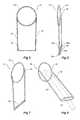
- Figures 1 to 4show a first embodiment of a stent graft and valve according to the present invention.
- Figure 1shows an outside view
- Figure 2shows a longitudinal cross section of the embodiment shown in Figure 1
- Figure 3shows the longitudinal cross section shown in Figure 2 but with a sheath of a medical device extending through the valve arrangement
- Figure 4shows a detailed view of the second end of the tube of the embodiment shown in Figure 1 .
- the stent graft 10comprises a tubular wall 12 of a biocompatible graft material.
- the tubular wallmay be supported by self-expanding or balloon expandable stents (not shown).
- the tubular walldefines an internal lumen 14.
- the fenestrationcan be bounded by a circular ring structure 17 stitched into the tubular wall 12.
- a valve assembly 18is fastened to the wall 12 around the fenestration and the valve assembly 18 extends within the internal lumen 14.
- the valve assembly 18is constructed to prevent fluid flow, such as blood flow, from passing through the fenestration from the internal lumen 14 to the outside of the stent graft.
- the valve assembly 18comprises a tube of graft material 20.
- the tube of graft materialhas a first end 22 and a second end 24, the first end 22 fastened to the wall 12 around the fenestration 16 and the tube extends into the internal lumen14 from the fenestration 16.
- Fluid pressuresuch as blood pressure on the outside surface of the tube of graft material, causes the tube to flatten out and lie against the inside of the wall 12 and therefore close off to prevent fluid flow through the tube.
- the valve assemblyhas a resilient wire reinforcing structure at the second end 24.
- the resilient wire reinforcing structureis formed from a pair of substantially parallel resilient struts 23a and 23b and arcuate structures 27a and 27b joining respective ends of the struts to form what is essentially flattened ring structure 26 at the second end 24 of the tube 20.
- the flattened ring structure 26can be formed from nitinol wire or stainless steel wire.
- the tube of graft materialis fastened by stitching 25, for instance, around the flattened ring structure 26, and by this means the second end of the tube of graft material is substantially closed off at the second end.
- Thisallows the two sides of the graft material to be close together and touch together to prevent fluid flow therethrough when the resilient ring is in its rest state.
- the flattened ring structure 26 and the tube 20 of graft materialcan be opened to enable the passing of a medical device therethrough.
- the flattened ring structurecan retain its rest shape, which will allow the two sides of the graft material to be close together and touch together to prevent fluid flow therethrough.
- the tube of graft materialcan comprise a resilient wire reinforcing structure, such as that shown in Figures 5 to 8 .
- the resilient wire reinforcing structure 30comprises two longitudinal struts 32, 34 extending along where the tube of graft material would be and on diametrically opposed sides thereof, a ring structure 36 at the first end of two longitudinal struts 32, 34 and a pair of arms 38 extending between the longitudinal struts 32, 34 at the second end of the tube of graft material.
- the pair of arms 38 extending between the longitudinal struts 32, 34 at the second end of the tube of graft materialessentially form a flattened ring in the same manner as discussed in relation to Figures 1 to 4 .
- the flattened ring structurecan be described as being formed from a pair of substantially parallel resilient struts 38a and 38b and arcuate structures 38c and 38d joining respective ends of the struts 38a and 38b.
- the second end of tube of graft materialis fastened around its circumference to the flattened ring.
- the second end of the tube of graft materialis substantially closed off at the second end, which assists in flattening the tube to prevent fluid flow therethrough when there is fluid pressure on the outside of the tube.
- the resilient wire reinforcing structurecan be formed from nitinol or stainless steel.
- the ring a ring structure 36 at the first end of two longitudinal struts 32, 34is fastened into the tubular wall 12 in use and provided support for the fenestration.
- the two longitudinal struts 32, 34 extending along the tube of graft materialcan have a bend 40 at their upper ends adjacent to the ring 36.
- the bends 40can be straightened out against the resiliency of the struts and the dilator and sheath can be directed in any desired direction.
- Figure 9shows a part of a stent graft with a valve arrangement according to the present invention with a dilator and sheath passed therethrough.
- the wall of the stent graft 12has a fenestration with the valve arrangement 18 mounted into a fenestration 16 in the wall.
- the valve assembly 18comprises a tube of graft material 20.
- the tube of graft materialhas a first end 22 and a second end 24, the first end 22 fastened to the wall 13 around the fenestration 16 and the tube extends into the internal lumen of the stent graft from the fenestration 16.
- the valve arrangementhas a resilient reinforcement structure 30.
- the resilient wire reinforcing structure 30comprises two longitudinal struts 32, 34 extending along the tube of graft material 20 on diametrically opposed sides thereof, a ring structure 36 at the first end of the tube of graft material is stitched around the fenestration 16 and holds open the fenestration.
- a pair of arms 38extend between the longitudinal struts 32, 34 at the second end 24 of the tube of graft material 20.
- the second end 24 of tube of graft materialis fastened around its circumference to the pair of arms by stitching 42.
- a dilator 50 and sheath 52have been deployed over a guide wire 54, which passes through the valve arrangement 18 and these have opened up the pair of arms 38 against the resiliency of the arms.
- the armsclose up the second end of the valve arrangement so that the sides of the tube engage each other due to liquid pressure outside the tube and close off the valve arrangement.
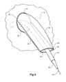
- Figure 10shows a perspective view of an alternative embodiment of a valve arrangement according to the present invention
- Figure 11shows a perspective view of the valve arrangement of Figure 9 with a sheath of a medical device shown schematically extending therethrough.
- the inside wall 61 of the stent graft 60has a fenestration with the valve arrangement 62 mounted into a fenestration 64 in the wall.
- the valve assembly 62comprises a tube of graft material 66.
- the tube of graft materialhas a first end 68 and a second end 70, the first end 68 fastened to the wall 61 around the fenestration 64 and the tube extending into the internal lumen of the stent graft from the fenestration 64.
- the tube of graft material 66 of the valve arrangement 62is formed from a flexible biocompatible graft material such as Dacron.
- the tube of graft material 66comprises a cross sectional shape changing from substantially circular at the first end 68 to be fastened around the fenestration 64 to a flattened cross section at the second end 70.
- the flexible nature of the tube of graft material 66allows it to hang down substantially parallel to the wall 61 of the stent graft 60. Fluid flow and pressure, such as by blood flow through the stent graft in use, on the outer surface of the tube of graft material causes the tube to hang down and be pressed against the wall of the stent graft and to thereby close off to prevent fluid flow through the tube of graft material 66. By deflection of the flattened cross section, the tube of graft material can be opened to a more tubular shape to enable the passing of a medical device therethrough.
- the tube of graft materialcomprises a biocompatible graft material which is heat set into the flattened cross section at the second end.
- the tube of graft materialcomprises a biocompatible graft material which is at least in part formed from a hybrid material able to be set into the flattened cross section at the second end.
- a hybrid materialwhich is able to be set into the flattened cross section at the second end can be interwoven nitinol and Dacron.
- a dilator 50 and sheath 52have been deployed over a guide wire 54 which passes through the valve arrangement 62 and these have opened up the flattened second end 70.
- the flattened end 70closes up again so that the sides of the tube engage each other due to liquid pressure outside the tube and close off the valve arrangement.
Landscapes
- Health & Medical Sciences (AREA)
- Engineering & Computer Science (AREA)
- Biomedical Technology (AREA)
- Heart & Thoracic Surgery (AREA)
- Oral & Maxillofacial Surgery (AREA)
- Transplantation (AREA)
- Cardiology (AREA)
- Vascular Medicine (AREA)
- Life Sciences & Earth Sciences (AREA)
- Animal Behavior & Ethology (AREA)
- General Health & Medical Sciences (AREA)
- Public Health (AREA)
- Veterinary Medicine (AREA)
- Pulmonology (AREA)
- Gastroenterology & Hepatology (AREA)
- Prostheses (AREA)
Abstract
Description
- This invention relates to a medical device and more particularly a device which can be deployed by endovascular means into the vasculature of a patient.
- There have been proposed endovascular devices which can be deployed into the vasculature, particularly in the region of the aortic bifurcation, so that an aneurysm in the aorta can be bridged by placement of the endovascular device with a proximal portion which seals into a non-aneurysed portion of the aorta adjacent to the renal arteries, a first leg which extends down one iliac artery to a non-aneurysed portion of the iliac artery and another short leg into which a leg extension may be placed to extend into a non-aneurysed portion of the contra-lateral iliac artery.
- There can be problems, however, if the aneurysm of the aorta extends down into one or other of the iliac arteries. Each of the common iliac arteries branches into the internal and external iliac arteries and it is necessary in such a situation that a blood flow path can be directed through an endovascular stent graft into each of these arteries. In particular, it is desirable to introduce a leg extension onto the internal iliac artery from a bifurcation in the endovascular device. Access to the internal iliac artery for a medical device introducer through an already placed stent graft can be difficult from the contralateral iliac artery and hence there has been proposed, such as in
US Patent Publication No. 20070250154 , the use of a valve to facilitate access to the internal iliac artery. An introducer for the leg extension can be placed through the valve and after introduction of the leg extension the introducer can be withdrawn and the valve can then close to prevent blood loss from the endovascular device into the aneurysed region. - The object of this invention is to provide an endovascularly deployed medical device with a valve arrangement which can assist in solving this problem or at least provide a physician with a useful alternative.
- Throughout this specification the term distal with respect to a portion of the aorta, a deployment device or a prosthesis means the end of the aorta, deployment device or prosthesis further away in the direction of blood flow away from the heart and the term proximal means the portion of the aorta, deployment device or end of the prosthesis nearer to the heart. When applied to other vessels, similar terms such as caudal and cranial should be understood.
- In one form, the invention comprises a stent graft comprising a graft material defining a cylindrical wall, an internal lumen within the cylindrical wall and a fenestration in the wall, the fenestration comprising a valve arrangement to prevent the flow of liquids from within the internal lumen to outside of the wall;
the valve arrangement extending within the internal lumen and comprising a tube of graft material;
the tube of graft material comprising a first end and a second end, the first end being fastened to the wall around the fenestration and the tube extending into the internal lumen therefrom;
the second end comprising a pair of substantially parallel resilient struts and arcuate structures joining respective ends of the struts, the tube of graft material being fastened to resilient struts whereby the second end of the tube of graft material is substantially closed off at the second end;
whereby fluid pressure on an outside surface of the tube of graft material causes the tube to close off between the first end and the second end to prevent fluid flow therethrough and by resilient deflection of the resilient struts the second end of the tube of graft material can be opened to enable the passing of a medical device therethrough. - Preferably, the tube of graft material further comprises a resilient wire reinforcing structure comprising two longitudinal struts extending along the tube of graft material on diametrically opposed sides thereof, a ring structure at the first end of the tube of graft material and the longitudinal struts at the second end of the tube of graft material being fastened to the arcuate structures. The resilient wire reinforcing structure can comprise nitinol or stainless steel.
- Each of the longitudinal struts can comprise a bend adjacent the first end thereof such that at rest the struts extend substantially parallel to the wall.
- The tube of graft material comprises a biocompatible graft material which is heat set into the flattened cross section at the second end.
- Alternatively, the tube of graft material can comprises a biocompatible graft material which is at least in part formed from a hybrid material able to be set into a flattened cross section at the second end. For instance, the hybrid material able to be set into the flattened cross section at the second end can comprise interwoven nitinol and Dacron.
- In an alternative form, the invention comprises a stent graft comprising a tubular body of a biocompatible graft material defining a main lumen therethrough, an aperture in the tubular body and a valve arrangement to prevent fluid flow through the aperture from the inside of the tubular body to the outside of the tubular body, the valve arrangement comprises a valve assembly comprising a valve tube of biocompatible graft material and a support structure for the valve tube within the main lumen, the support structure comprising a pair of substantially parallel and spaced apart arms, a ring structure at one end of the spaced apart arms and a flattened ring structure at the other end of the spaced arms, the ring structure being fastened to the tubular body around the aperture and the valve tube comprising a first end and a second end, the first end of the valve tube being fastened around the ring structure at the one end of the spaced apart arms and the second end of the valve tube being fastened around the flattened ring structure at the other end of the spaced arms, at least the flattened ring structure at the other end of the spaced arms being formed of a resilient material such that the flattened ring structure can be opened by passing an object therethrough and returned to a closed state upon removal of the object.
- Preferably, the pair of substantially parallel and spaced apart arms comprise a bend at the one end whereby the valve tube extends substantially along the tubular body.
- In one embodiment, the tube of graft material comprises a cross sectional shape changing from substantially circular at the first end to be fastened around the fenestration to a flattened cross section at the second end to prevent fluid flow therethrough but by deflection of the flattened cross section the tube of graft material can be opened to enable the passing of a medical device therethrough.
- Preferably, the tube of graft material comprises a biocompatible graft material which is heat set into the flattened cross section at the second end. Alternatively, the tube of graft material comprises a biocompatible graft material which is at least in part formed from a hybrid material able to be set into the flattened cross section at the second end. The hybrid material able to be set into the flattened cross section at the second end can comprise interwoven nitinol and Dacron.
- In an alternative form, the invention comprises a valve arrangement in a wall of a stent graft, the wall defining an internal lumen of the stent graft;
a fenestration in the wall;
the valve arrangement extending within the internal lumen;
the valve arrangement comprising a tube of graft material;
the tube of graft material comprising a first end and a second end, the first end being fastened to the wall around the fenestration and the tube extending into the internal lumen;
whereby fluid pressure on the tube of graft material causes the tube to close off to prevent fluid flow therethrough. - In an alternative form, the invention comprises a valve arrangement in a wall of a stent graft, the wall defining an internal lumen of the stent graft;
a fenestration in the wall;
the valve arrangement comprising a tube of graft material supported at least in part by a resilient wire reinforcing structure;
the tube of graft material comprising a first end and a second end, the first end being fastened to the wall around the fenestration and the tube extending into the internal lumen;
the resilient wire reinforcing structure comprising two longitudinal struts extending along the tube of graft material on diametrically opposed sides thereof, a ring structure at the first end of the tube of graft material and a pair of substantially straight arms extending between the longitudinal struts at the second end of the tube of graft material, the tube of graft material being fastened to the pair of arms at the second end;
whereby the second end of the tube of graft material is closed off at the second end to prevent fluid flow therethrough but by resilient deflection of the pair of substantially straight arms, the tube of graft material can be opened to enable the passing of a device therethrough. - It will be seen by the various forms of the invention there is provided a valve arrangement and a stent graft with a valve arrangement through which a medical device can be deployed but upon removal of the medical device, the valve automatically closes to prevent fluid such as blood flowing through it.
- While Dacron, expanded polytetrafluoroethylene (ePTFE), or other synthetic biocompatible materials can be used for the tubular graft material for the stent graft and the valve tube, a naturally occurring biomaterial, such as collagen, is highly desirable, particularly a specially derived collagen material known as an extracellular matrix (ECM), such as small intestinal submucosa (SIS). Besides SIS, examples of ECM's include pericardium, stomach submucosa, liver basement membrane, urinary bladder submucosa, tissue mucosa, and dura mater.
- SIS is particularly useful, and can be made in the fashion described in
Badylak et al., US Patent 4,902,508 ; Intestinal Collagen Layer described inUS Patent 5,733,337 to Carr and in17 Nature Biotechnology 1083 (Nov. 1999); Cook et al., WIPO PublicationWO 98/22158, dated 28 May 1998 PCT/US97/14855 US Patents 5,968,096 ;5,955,110 ;5,885,619 ; and5,711,969 . In addition to xenogenic biomaterials, such as SIS, autologous tissue can be harvested as well, for use in forming the tubular graft material. Additionally, Elastin or Elastin-Like Polypetides (ELPs) and the like offer potential as a material to fabricate the tubular graft material to form a device with exceptional biocompatibility. - SIS is available from Cook Biotech, West Lafayette, Indiana, USA.
- It will be seen that by this invention there is provided a stent graft with a valve arrangement. The valve arrangement allows an indwelling catheter to be provided through the valve into a side arm in the iliac artery at the time of deployment to assist with deployment of a leg extension into the internal iliac artery.
- This then generally describes the invention but to assist with understanding, reference will now be made to the accompanying drawings which show embodiments of the invention.
- In the drawings;
Figure 1 shows a first embodiment of stent graft according to the present invention;Figure 2 shows a longitudinal cross section of the embodiment shown inFigure 1 ;Figure 3 shows the longitudinal cross section shown inFigure 2 but with a sheath of a medical device extending through the valve arrangement;Figure 4 shows a detailed view of the second end of the tube of the embodiment shown inFigure 1 ;Figure 5 shows a front view of wire reinforcement suitable for a valve arrangement of an alternate embodiment of valve arrangement;Figure 6 shows a side view of the wire reinforcement shown inFigure 5 ;Figure 7 shows a perspective view of the wire reinforcement shown inFigure 5 ;Figure 8 shows the perspective view as inFigure 7 but with a sheath of a medical device shown schematically extending therethrough;Figure 9 shows a perspective view of a valve arrangement incorporating the wire reinforcement ofFigures 5 to 8 and with a sheath of a medical device shown schematically extending therethrough;Figure 10 shows a perspective view of an alternative embodiment of a valve according to the present invention; andFigure 11 shows a perspective view of the valve arrangement ofFigure 10 with a sheath of a medical device shown schematically extending therethrough.Figures 1 to 4 show a first embodiment of a stent graft and valve according to the present invention.Figure 1 shows an outside view,Figure 2 shows a longitudinal cross section of the embodiment shown inFigure 1, Figure 3 shows the longitudinal cross section shown inFigure 2 but with a sheath of a medical device extending through the valve arrangement andFigure 4 shows a detailed view of the second end of the tube of the embodiment shown inFigure 1 .- The
stent graft 10 comprises atubular wall 12 of a biocompatible graft material. The tubular wall may be supported by self-expanding or balloon expandable stents (not shown).The tubular wall defines aninternal lumen 14. There is afenestration 16 in thewall 12. The fenestration can be bounded by acircular ring structure 17 stitched into thetubular wall 12. Avalve assembly 18 is fastened to thewall 12 around the fenestration and thevalve assembly 18 extends within theinternal lumen 14. Thevalve assembly 18 is constructed to prevent fluid flow, such as blood flow, from passing through the fenestration from theinternal lumen 14 to the outside of the stent graft. - The
valve assembly 18 comprises a tube ofgraft material 20. The tube of graft material has afirst end 22 and asecond end 24, thefirst end 22 fastened to thewall 12 around thefenestration 16 and the tube extends into the internal lumen14 from thefenestration 16. Fluid pressure, such as blood pressure on the outside surface of the tube of graft material, causes the tube to flatten out and lie against the inside of thewall 12 and therefore close off to prevent fluid flow through the tube. - The valve assembly has a resilient wire reinforcing structure at the
second end 24. The resilient wire reinforcing structure is formed from a pair of substantially parallelresilient struts arcuate structures ring structure 26 at thesecond end 24 of thetube 20. The flattenedring structure 26 can be formed from nitinol wire or stainless steel wire. - The tube of graft material is fastened by stitching 25, for instance, around the flattened
ring structure 26, and by this means the second end of the tube of graft material is substantially closed off at the second end. This allows the two sides of the graft material to be close together and touch together to prevent fluid flow therethrough when the resilient ring is in its rest state. By resilient deflection of the flattenedring structure 26, such as by passing a dilator and sheath therethrough, the flattenedring structure 26 and thetube 20 of graft material can be opened to enable the passing of a medical device therethrough. Upon removal of the medical device, the flattened ring structure can retain its rest shape, which will allow the two sides of the graft material to be close together and touch together to prevent fluid flow therethrough. - Additionally, the tube of graft material can comprise a resilient wire reinforcing structure, such as that shown in
Figures 5 to 8 . For clarity, the resilient wire reinforcing structure shown inFigures 5 to 8 does not show the tube of graft material. The resilientwire reinforcing structure 30 comprises twolongitudinal struts ring structure 36 at the first end of twolongitudinal struts arms 38 extending between thelongitudinal struts arms 38 extending between thelongitudinal struts Figures 1 to 4 . - As with the earlier embodiment, the flattened ring structure can be described as being formed from a pair of substantially parallel
resilient struts arcuate structures struts - The second end of tube of graft material is fastened around its circumference to the flattened ring. By this arrangement, the second end of the tube of graft material is substantially closed off at the second end, which assists in flattening the tube to prevent fluid flow therethrough when there is fluid pressure on the outside of the tube. By resilient deflection of the pair of arms, such as by passing a dilator and sheath therethrough, the pair of arms and the tube of graft material can be opened to enable the passing of a medical device therethrough. The resilient wire reinforcing structure can be formed from nitinol or stainless steel.
- The ring a
ring structure 36 at the first end of twolongitudinal struts tubular wall 12 in use and provided support for the fenestration. - To assist with the tube of graft material lying against the inside wall of the stent graft at rest, and thereby providing minimum obstruction to the flow of liquid such as blood through the stent graft, the two
longitudinal struts bend 40 at their upper ends adjacent to thering 36. When a dilator and sheath is passed through the tube of graft material, thebends 40 can be straightened out against the resiliency of the struts and the dilator and sheath can be directed in any desired direction. Figure 9 shows a part of a stent graft with a valve arrangement according to the present invention with a dilator and sheath passed therethrough.- The wall of the
stent graft 12 has a fenestration with thevalve arrangement 18 mounted into afenestration 16 in the wall. Thevalve assembly 18 comprises a tube ofgraft material 20. The tube of graft material has afirst end 22 and asecond end 24, thefirst end 22 fastened to the wall 13 around thefenestration 16 and the tube extends into the internal lumen of the stent graft from thefenestration 16. The valve arrangement has aresilient reinforcement structure 30. The resilientwire reinforcing structure 30 comprises twolongitudinal struts graft material 20 on diametrically opposed sides thereof, aring structure 36 at the first end of the tube of graft material is stitched around thefenestration 16 and holds open the fenestration. A pair ofarms 38 extend between thelongitudinal struts second end 24 of the tube ofgraft material 20. Thesecond end 24 of tube of graft material is fastened around its circumference to the pair of arms by stitching 42. - In this illustration, a
dilator 50 andsheath 52 have been deployed over aguide wire 54, which passes through thevalve arrangement 18 and these have opened up the pair ofarms 38 against the resiliency of the arms. When thedilator 50 andsheath 52 are removed, the arms close up the second end of the valve arrangement so that the sides of the tube engage each other due to liquid pressure outside the tube and close off the valve arrangement. Figure 10 shows a perspective view of an alternative embodiment of a valve arrangement according to the present invention andFigure 11 shows a perspective view of the valve arrangement ofFigure 9 with a sheath of a medical device shown schematically extending therethrough.- In this embodiment, the
inside wall 61 of thestent graft 60 has a fenestration with thevalve arrangement 62 mounted into afenestration 64 in the wall. Thevalve assembly 62 comprises a tube ofgraft material 66. The tube of graft material has afirst end 68 and asecond end 70, thefirst end 68 fastened to thewall 61 around thefenestration 64 and the tube extending into the internal lumen of the stent graft from thefenestration 64. The tube ofgraft material 66 of thevalve arrangement 62 is formed from a flexible biocompatible graft material such as Dacron. The tube ofgraft material 66 comprises a cross sectional shape changing from substantially circular at thefirst end 68 to be fastened around thefenestration 64 to a flattened cross section at thesecond end 70. - The flexible nature of the tube of
graft material 66 allows it to hang down substantially parallel to thewall 61 of thestent graft 60. Fluid flow and pressure, such as by blood flow through the stent graft in use, on the outer surface of the tube of graft material causes the tube to hang down and be pressed against the wall of the stent graft and to thereby close off to prevent fluid flow through the tube ofgraft material 66. By deflection of the flattened cross section, the tube of graft material can be opened to a more tubular shape to enable the passing of a medical device therethrough. - In one embodiment, the tube of graft material comprises a biocompatible graft material which is heat set into the flattened cross section at the second end.
- Alternatively, the tube of graft material comprises a biocompatible graft material which is at least in part formed from a hybrid material able to be set into the flattened cross section at the second end. Such a hybrid material which is able to be set into the flattened cross section at the second end can be interwoven nitinol and Dacron.
- In
Figure 11 , adilator 50 andsheath 52 have been deployed over aguide wire 54 which passes through thevalve arrangement 62 and these have opened up the flattenedsecond end 70. When thedilator 50 andsheath 52 are removed, the flattenedend 70 closes up again so that the sides of the tube engage each other due to liquid pressure outside the tube and close off the valve arrangement. - All optional and preferred features and modifications of the described embodiments and dependent claims are usable in all aspects of the invention taught herein. Furthermore, the individual features of the dependent claims, as well as all optional and preferred features and modifications of the described embodiments are combinable and interchangeable with one another.
Claims (4)
- A valve arrangement (18) in a wall (12) of a stent graft (10), the wall defining an internal lumen (14) of the stent graft;
a fenestration (16) in the wall;
the valve arrangement extending within the internal lumen;
the valve arrangement comprising a tube of graft material (20);
the tube of graft material comprising a first end (22) and a second end (24), the first end being fastened to the wall around the fenestration and the tube extending into the internal lumen;
whereby fluid pressure on the tube of graft material causes the tube to close off to prevent fluid flow therethrough;
the tube of graft material (20) comprising a cross sectional shape changing from substantially circular at the first end (22) to be fastened around the fenestration to a flattened cross section at the second end (24) to prevent fluid flow therethrough but by deflection of the flattened cross section the tube of graft material can be opened to enable the passing of a medical device therethrough. - A stent graft as in Claim 1, wherein the tube of graft material (20), comprises a biocompatible graft material which is heat set into the flattened cross section at the second end.
- A stent graft as in Claim 1, wherein the tube of graft material (20) comprises a biocompatible graft material which is at least in part formed from a hybrid material able to be set into the flattened cross section at the second end.
- A stent graft as in Claim 3, wherein the hybrid material able to be set into the flattened cross section at the second end (24) comprises interwoven nitinol and Dacron.
Applications Claiming Priority (1)
| Application Number | Priority Date | Filing Date | Title |
|---|---|---|---|
| AU2013254913AAU2013254913B1 (en) | 2013-11-04 | 2013-11-04 | Stent graft with valve arrangement |
Publications (2)
| Publication Number | Publication Date |
|---|---|
| EP2868294A1true EP2868294A1 (en) | 2015-05-06 |
| EP2868294B1 EP2868294B1 (en) | 2016-01-20 |
Family
ID=51266245
Family Applications (1)
| Application Number | Title | Priority Date | Filing Date |
|---|---|---|---|
| EP14275165.0AActiveEP2868294B1 (en) | 2013-11-04 | 2014-08-06 | Stent graft with a valve arrangement |
Country Status (3)
| Country | Link |
|---|---|
| US (1) | US9622887B2 (en) |
| EP (1) | EP2868294B1 (en) |
| AU (1) | AU2013254913B1 (en) |
Families Citing this family (6)
| Publication number | Priority date | Publication date | Assignee | Title |
|---|---|---|---|---|
| US10966850B2 (en) | 2014-03-06 | 2021-04-06 | W. L. Gore & Associates, Inc. | Implantable medical device constraint and deployment apparatus |
| US10537419B2 (en)* | 2016-10-27 | 2020-01-21 | Cook Medical Technologies Llc | Prosthesis with branched portion |
| US12268619B2 (en)* | 2019-10-15 | 2025-04-08 | Merit Medical Systems, Inc. | Endovascular prosthesis with selectively openable internal duct |
| CN112773560A (en)* | 2021-01-29 | 2021-05-11 | 北京华脉泰科医疗器械有限公司 | Covered stent and method for manufacturing covered stent |
| EP4586970A1 (en)* | 2022-09-15 | 2025-07-23 | Endospan Ltd. | Double-branching ascending aortic stent-graft systems |
| US20240156626A1 (en)* | 2022-11-14 | 2024-05-16 | Merit Medical Systems, Inc. | Stent with remote manipulation |
Citations (9)
| Publication number | Priority date | Publication date | Assignee | Title |
|---|---|---|---|---|
| US4902508A (en) | 1988-07-11 | 1990-02-20 | Purdue Research Foundation | Tissue graft composition |
| US5711969A (en) | 1995-04-07 | 1998-01-27 | Purdue Research Foundation | Large area submucosal tissue graft constructs |
| US5733337A (en) | 1995-04-07 | 1998-03-31 | Organogenesis, Inc. | Tissue repair fabric |
| WO1998022158A2 (en) | 1996-08-23 | 1998-05-28 | Cook Biotech, Incorporated | Graft prosthesis, materials and methods |
| US5968096A (en) | 1996-04-05 | 1999-10-19 | Purdue Research Foundation | Method of repairing perforated submucosal tissue graft constructs |
| US20070250154A1 (en) | 2006-04-19 | 2007-10-25 | William A. Cook Australia Pty Ltd. | Twin bifurcated stent graft |
| EP2522306A1 (en)* | 2011-05-09 | 2012-11-14 | Cook Medical Technologies LLC | Paraplegia prevention valve for stent grafts |
| EP2609895A2 (en)* | 2011-12-28 | 2013-07-03 | Roy K. Greenberg | Endoluminal prosthesis with valve arrangement |
| US9714855B2 (en) | 2015-01-26 | 2017-07-25 | Arad Ltd. | Ultrasonic water meter |
Family Cites Families (16)
| Publication number | Priority date | Publication date | Assignee | Title |
|---|---|---|---|---|
| US5591195A (en)* | 1995-10-30 | 1997-01-07 | Taheri; Syde | Apparatus and method for engrafting a blood vessel |
| EP1723931B1 (en)* | 1996-11-04 | 2012-01-04 | Advanced Stent Technologies, Inc. | Extendible stent apparatus and method for deploying the same |
| US8092511B2 (en)* | 2000-03-03 | 2012-01-10 | Endovascular Technologies, Inc. | Modular stent-graft for endovascular repair of aortic arch aneurysms and dissections |
| US6494909B2 (en)* | 2000-12-01 | 2002-12-17 | Prodesco, Inc. | Endovascular valve |
| JP2003250907A (en)* | 2002-03-05 | 2003-09-09 | Terumo Corp | Stent |
| US6676699B2 (en)* | 2002-04-26 | 2004-01-13 | Medtronic Ave, Inc | Stent graft with integrated valve device and method |
| US20050059923A1 (en) | 2003-09-17 | 2005-03-17 | Ricardo Gamboa | Fenestration with intrinsic means of selective closure incorporated to a tubular body and used in interventional cardiovascular procedures |
| WO2008057569A1 (en)* | 2006-11-07 | 2008-05-15 | William A. Cook Australia Pty. Ltd. | Stent graft for treatment of an emergency rupture of a vessel |
| WO2009020653A1 (en)* | 2007-08-08 | 2009-02-12 | Cleveland Clinic Foundation | Branched stent graft system |
| US8163004B2 (en)* | 2008-02-18 | 2012-04-24 | Aga Medical Corporation | Stent graft for reinforcement of vascular abnormalities and associated method |
| AU2010201067B1 (en)* | 2010-03-19 | 2011-06-09 | Cook Incorporated | Thoracic stent graft |
| US20110257725A1 (en)* | 2010-04-20 | 2011-10-20 | Medtronic Vascular, Inc. | Blood Inflating Prosthesis |
| AU2011200858B1 (en)* | 2011-02-28 | 2012-04-05 | Cook Medical Technologies Llc | Stent graft with valve arrangement |
| US20120253471A1 (en) | 2011-04-04 | 2012-10-04 | Medtronic Vascular, Inc. | Variable Length Airway Stent Graft With One-Way Valves |
| EP2810622B1 (en) | 2012-01-30 | 2019-04-24 | Kawasumi Laboratories, Inc. | Biliary stent |
| WO2015075708A1 (en)* | 2013-11-19 | 2015-05-28 | Endospan Ltd. | Stent system with radial-expansion locking |
- 2013
- 2013-11-04AUAU2013254913Apatent/AU2013254913B1/enactiveActive
- 2014
- 2014-08-06EPEP14275165.0Apatent/EP2868294B1/enactiveActive
- 2014-11-03USUS14/530,866patent/US9622887B2/enactiveActive
Patent Citations (11)
| Publication number | Priority date | Publication date | Assignee | Title |
|---|---|---|---|---|
| US4902508A (en) | 1988-07-11 | 1990-02-20 | Purdue Research Foundation | Tissue graft composition |
| US5711969A (en) | 1995-04-07 | 1998-01-27 | Purdue Research Foundation | Large area submucosal tissue graft constructs |
| US5733337A (en) | 1995-04-07 | 1998-03-31 | Organogenesis, Inc. | Tissue repair fabric |
| US5885619A (en) | 1995-04-07 | 1999-03-23 | Purdue Research Foundation | Large area submucosal tissue graft constructs and method for making the same |
| US5955110A (en) | 1995-04-07 | 1999-09-21 | Purdue Research Foundation, Inc. | Multilayered submucosal graft constructs and method for making the same |
| US5968096A (en) | 1996-04-05 | 1999-10-19 | Purdue Research Foundation | Method of repairing perforated submucosal tissue graft constructs |
| WO1998022158A2 (en) | 1996-08-23 | 1998-05-28 | Cook Biotech, Incorporated | Graft prosthesis, materials and methods |
| US20070250154A1 (en) | 2006-04-19 | 2007-10-25 | William A. Cook Australia Pty Ltd. | Twin bifurcated stent graft |
| EP2522306A1 (en)* | 2011-05-09 | 2012-11-14 | Cook Medical Technologies LLC | Paraplegia prevention valve for stent grafts |
| EP2609895A2 (en)* | 2011-12-28 | 2013-07-03 | Roy K. Greenberg | Endoluminal prosthesis with valve arrangement |
| US9714855B2 (en) | 2015-01-26 | 2017-07-25 | Arad Ltd. | Ultrasonic water meter |
Non-Patent Citations (1)
| Title |
|---|
| NATURE BIOTECHNOLOGY, vol. 17, November 1999 (1999-11-01), pages 1083 |
Also Published As
| Publication number | Publication date |
|---|---|
| EP2868294B1 (en) | 2016-01-20 |
| US9622887B2 (en) | 2017-04-18 |
| AU2013254913B1 (en) | 2014-09-25 |
| US20150127089A1 (en) | 2015-05-07 |
Similar Documents
| Publication | Publication Date | Title |
|---|---|---|
| US10143576B2 (en) | Twin bifurcated stent graft | |
| US8480726B2 (en) | Stent graft with valve arrangement | |
| US8118855B2 (en) | Curve forming stent graft | |
| CN1867302B (en) | stent graft fenestration | |
| US8021419B2 (en) | Stent graft | |
| EP2868294B1 (en) | Stent graft with a valve arrangement | |
| US9931231B2 (en) | Support structures for prostheses with branching portions | |
| EP1666003A1 (en) | Prosthesis comprising a stent with a tapered central portion | |
| JP2005537824A (en) | Thoracic aortic aneurysm stent graft | |
| US10368977B2 (en) | Endograft with at least two branch portions | |
| EP3351210A1 (en) | Branch stent retention cuff | |
| US10709544B2 (en) | Non-cylindrical variable pitch mesh top stent | |
| US10959826B2 (en) | Support structure for scalloped grafts | |
| CN117122443A (en) | Branched stent graft with support stent | |
| US10709543B2 (en) | Non-cylindrical mesh top stent with twisted sections | |
| EP3278767A1 (en) | An endograft for treating branched vessels | |
| AU2011250799B2 (en) | Bifurcated stent graft with valve | |
| AU2011250798A1 (en) | Bifurcated-bifurcated stent graft |
Legal Events
| Date | Code | Title | Description |
|---|---|---|---|
| PUAI | Public reference made under article 153(3) epc to a published international application that has entered the european phase | Free format text:ORIGINAL CODE: 0009012 | |
| 17P | Request for examination filed | Effective date:20150326 | |
| AK | Designated contracting states | Kind code of ref document:A1 Designated state(s):AL AT BE BG CH CY CZ DE DK EE ES FI FR GB GR HR HU IE IS IT LI LT LU LV MC MK MT NL NO PL PT RO RS SE SI SK SM TR | |
| AX | Request for extension of the european patent | Extension state:BA ME | |
| GRAP | Despatch of communication of intention to grant a patent | Free format text:ORIGINAL CODE: EPIDOSNIGR1 | |
| RIC1 | Information provided on ipc code assigned before grant | Ipc:A61F 2/07 20130101AFI20150821BHEP | |
| INTG | Intention to grant announced | Effective date:20150918 | |
| GRAS | Grant fee paid | Free format text:ORIGINAL CODE: EPIDOSNIGR3 | |
| GRAA | (expected) grant | Free format text:ORIGINAL CODE: 0009210 | |
| AK | Designated contracting states | Kind code of ref document:B1 Designated state(s):AL AT BE BG CH CY CZ DE DK EE ES FI FR GB GR HR HU IE IS IT LI LT LU LV MC MK MT NL NO PL PT RO RS SE SI SK SM TR | |
| REG | Reference to a national code | Ref country code:GB Ref legal event code:FG4D | |
| REG | Reference to a national code | Ref country code:CH Ref legal event code:EP | |
| REG | Reference to a national code | Ref country code:IE Ref legal event code:FG4D | |
| REG | Reference to a national code | Ref country code:AT Ref legal event code:REF Ref document number:771355 Country of ref document:AT Kind code of ref document:T Effective date:20160215 | |
| REG | Reference to a national code | Ref country code:DE Ref legal event code:R096 Ref document number:602014000799 Country of ref document:DE | |
| REG | Reference to a national code | Ref country code:LT Ref legal event code:MG4D Ref country code:NL Ref legal event code:MP Effective date:20160120 | |
| REG | Reference to a national code | Ref country code:AT Ref legal event code:MK05 Ref document number:771355 Country of ref document:AT Kind code of ref document:T Effective date:20160120 | |
| PG25 | Lapsed in a contracting state [announced via postgrant information from national office to epo] | Ref country code:NL Free format text:LAPSE BECAUSE OF FAILURE TO SUBMIT A TRANSLATION OF THE DESCRIPTION OR TO PAY THE FEE WITHIN THE PRESCRIBED TIME-LIMIT Effective date:20160120 | |
| PG25 | Lapsed in a contracting state [announced via postgrant information from national office to epo] | Ref country code:IT Free format text:LAPSE BECAUSE OF FAILURE TO SUBMIT A TRANSLATION OF THE DESCRIPTION OR TO PAY THE FEE WITHIN THE PRESCRIBED TIME-LIMIT Effective date:20160120 Ref country code:HR Free format text:LAPSE BECAUSE OF FAILURE TO SUBMIT A TRANSLATION OF THE DESCRIPTION OR TO PAY THE FEE WITHIN THE PRESCRIBED TIME-LIMIT Effective date:20160120 Ref country code:GR Free format text:LAPSE BECAUSE OF FAILURE TO SUBMIT A TRANSLATION OF THE DESCRIPTION OR TO PAY THE FEE WITHIN THE PRESCRIBED TIME-LIMIT Effective date:20160421 Ref country code:NO Free format text:LAPSE BECAUSE OF FAILURE TO SUBMIT A TRANSLATION OF THE DESCRIPTION OR TO PAY THE FEE WITHIN THE PRESCRIBED TIME-LIMIT Effective date:20160420 Ref country code:FI Free format text:LAPSE BECAUSE OF FAILURE TO SUBMIT A TRANSLATION OF THE DESCRIPTION OR TO PAY THE FEE WITHIN THE PRESCRIBED TIME-LIMIT Effective date:20160120 Ref country code:ES Free format text:LAPSE BECAUSE OF FAILURE TO SUBMIT A TRANSLATION OF THE DESCRIPTION OR TO PAY THE FEE WITHIN THE PRESCRIBED TIME-LIMIT Effective date:20160120 | |
| PG25 | Lapsed in a contracting state [announced via postgrant information from national office to epo] | Ref country code:PT Free format text:LAPSE BECAUSE OF FAILURE TO SUBMIT A TRANSLATION OF THE DESCRIPTION OR TO PAY THE FEE WITHIN THE PRESCRIBED TIME-LIMIT Effective date:20160520 Ref country code:IS Free format text:LAPSE BECAUSE OF FAILURE TO SUBMIT A TRANSLATION OF THE DESCRIPTION OR TO PAY THE FEE WITHIN THE PRESCRIBED TIME-LIMIT Effective date:20160520 Ref country code:LT Free format text:LAPSE BECAUSE OF FAILURE TO SUBMIT A TRANSLATION OF THE DESCRIPTION OR TO PAY THE FEE WITHIN THE PRESCRIBED TIME-LIMIT Effective date:20160120 Ref country code:AT Free format text:LAPSE BECAUSE OF FAILURE TO SUBMIT A TRANSLATION OF THE DESCRIPTION OR TO PAY THE FEE WITHIN THE PRESCRIBED TIME-LIMIT Effective date:20160120 Ref country code:PL Free format text:LAPSE BECAUSE OF FAILURE TO SUBMIT A TRANSLATION OF THE DESCRIPTION OR TO PAY THE FEE WITHIN THE PRESCRIBED TIME-LIMIT Effective date:20160120 Ref country code:SE Free format text:LAPSE BECAUSE OF FAILURE TO SUBMIT A TRANSLATION OF THE DESCRIPTION OR TO PAY THE FEE WITHIN THE PRESCRIBED TIME-LIMIT Effective date:20160120 Ref country code:RS Free format text:LAPSE BECAUSE OF FAILURE TO SUBMIT A TRANSLATION OF THE DESCRIPTION OR TO PAY THE FEE WITHIN THE PRESCRIBED TIME-LIMIT Effective date:20160120 Ref country code:LV Free format text:LAPSE BECAUSE OF FAILURE TO SUBMIT A TRANSLATION OF THE DESCRIPTION OR TO PAY THE FEE WITHIN THE PRESCRIBED TIME-LIMIT Effective date:20160120 | |
| REG | Reference to a national code | Ref country code:DE Ref legal event code:R097 Ref document number:602014000799 Country of ref document:DE | |
| PG25 | Lapsed in a contracting state [announced via postgrant information from national office to epo] | Ref country code:EE Free format text:LAPSE BECAUSE OF FAILURE TO SUBMIT A TRANSLATION OF THE DESCRIPTION OR TO PAY THE FEE WITHIN THE PRESCRIBED TIME-LIMIT Effective date:20160120 Ref country code:DK Free format text:LAPSE BECAUSE OF FAILURE TO SUBMIT A TRANSLATION OF THE DESCRIPTION OR TO PAY THE FEE WITHIN THE PRESCRIBED TIME-LIMIT Effective date:20160120 | |
| PLBE | No opposition filed within time limit | Free format text:ORIGINAL CODE: 0009261 | |
| STAA | Information on the status of an ep patent application or granted ep patent | Free format text:STATUS: NO OPPOSITION FILED WITHIN TIME LIMIT | |
| PG25 | Lapsed in a contracting state [announced via postgrant information from national office to epo] | Ref country code:SM Free format text:LAPSE BECAUSE OF FAILURE TO SUBMIT A TRANSLATION OF THE DESCRIPTION OR TO PAY THE FEE WITHIN THE PRESCRIBED TIME-LIMIT Effective date:20160120 Ref country code:RO Free format text:LAPSE BECAUSE OF FAILURE TO SUBMIT A TRANSLATION OF THE DESCRIPTION OR TO PAY THE FEE WITHIN THE PRESCRIBED TIME-LIMIT Effective date:20160120 Ref country code:SK Free format text:LAPSE BECAUSE OF FAILURE TO SUBMIT A TRANSLATION OF THE DESCRIPTION OR TO PAY THE FEE WITHIN THE PRESCRIBED TIME-LIMIT Effective date:20160120 Ref country code:CZ Free format text:LAPSE BECAUSE OF FAILURE TO SUBMIT A TRANSLATION OF THE DESCRIPTION OR TO PAY THE FEE WITHIN THE PRESCRIBED TIME-LIMIT Effective date:20160120 | |
| 26N | No opposition filed | Effective date:20161021 | |
| PG25 | Lapsed in a contracting state [announced via postgrant information from national office to epo] | Ref country code:BE Free format text:LAPSE BECAUSE OF FAILURE TO SUBMIT A TRANSLATION OF THE DESCRIPTION OR TO PAY THE FEE WITHIN THE PRESCRIBED TIME-LIMIT Effective date:20160120 | |
| PG25 | Lapsed in a contracting state [announced via postgrant information from national office to epo] | Ref country code:BG Free format text:LAPSE BECAUSE OF FAILURE TO SUBMIT A TRANSLATION OF THE DESCRIPTION OR TO PAY THE FEE WITHIN THE PRESCRIBED TIME-LIMIT Effective date:20160420 Ref country code:SI Free format text:LAPSE BECAUSE OF FAILURE TO SUBMIT A TRANSLATION OF THE DESCRIPTION OR TO PAY THE FEE WITHIN THE PRESCRIBED TIME-LIMIT Effective date:20160120 | |
| PG25 | Lapsed in a contracting state [announced via postgrant information from national office to epo] | Ref country code:MC Free format text:LAPSE BECAUSE OF FAILURE TO SUBMIT A TRANSLATION OF THE DESCRIPTION OR TO PAY THE FEE WITHIN THE PRESCRIBED TIME-LIMIT Effective date:20160120 | |
| REG | Reference to a national code | Ref country code:FR Ref legal event code:ST Effective date:20170428 | |
| PG25 | Lapsed in a contracting state [announced via postgrant information from national office to epo] | Ref country code:FR Free format text:LAPSE BECAUSE OF NON-PAYMENT OF DUE FEES Effective date:20160831 | |
| PG25 | Lapsed in a contracting state [announced via postgrant information from national office to epo] | Ref country code:LU Free format text:LAPSE BECAUSE OF NON-PAYMENT OF DUE FEES Effective date:20160806 | |
| REG | Reference to a national code | Ref country code:CH Ref legal event code:PL | |
| PG25 | Lapsed in a contracting state [announced via postgrant information from national office to epo] | Ref country code:CH Free format text:LAPSE BECAUSE OF NON-PAYMENT OF DUE FEES Effective date:20170831 Ref country code:LI Free format text:LAPSE BECAUSE OF NON-PAYMENT OF DUE FEES Effective date:20170831 | |
| PG25 | Lapsed in a contracting state [announced via postgrant information from national office to epo] | Ref country code:HU Free format text:LAPSE BECAUSE OF FAILURE TO SUBMIT A TRANSLATION OF THE DESCRIPTION OR TO PAY THE FEE WITHIN THE PRESCRIBED TIME-LIMIT; INVALID AB INITIO Effective date:20140806 | |
| PG25 | Lapsed in a contracting state [announced via postgrant information from national office to epo] | Ref country code:CY Free format text:LAPSE BECAUSE OF FAILURE TO SUBMIT A TRANSLATION OF THE DESCRIPTION OR TO PAY THE FEE WITHIN THE PRESCRIBED TIME-LIMIT Effective date:20160120 Ref country code:MK Free format text:LAPSE BECAUSE OF FAILURE TO SUBMIT A TRANSLATION OF THE DESCRIPTION OR TO PAY THE FEE WITHIN THE PRESCRIBED TIME-LIMIT Effective date:20160120 Ref country code:MT Free format text:LAPSE BECAUSE OF NON-PAYMENT OF DUE FEES Effective date:20160831 | |
| PG25 | Lapsed in a contracting state [announced via postgrant information from national office to epo] | Ref country code:TR Free format text:LAPSE BECAUSE OF FAILURE TO SUBMIT A TRANSLATION OF THE DESCRIPTION OR TO PAY THE FEE WITHIN THE PRESCRIBED TIME-LIMIT Effective date:20160120 Ref country code:AL Free format text:LAPSE BECAUSE OF FAILURE TO SUBMIT A TRANSLATION OF THE DESCRIPTION OR TO PAY THE FEE WITHIN THE PRESCRIBED TIME-LIMIT Effective date:20160120 | |
| P01 | Opt-out of the competence of the unified patent court (upc) registered | Effective date:20230602 | |
| PGFP | Annual fee paid to national office [announced via postgrant information from national office to epo] | Ref country code:DE Payment date:20240625 Year of fee payment:11 Ref country code:IE Payment date:20240726 Year of fee payment:11 | |
| PGFP | Annual fee paid to national office [announced via postgrant information from national office to epo] | Ref country code:GB Payment date:20240711 Year of fee payment:11 |