EP2868289A1 - Flexible catheter with a drive shaft - Google Patents
Flexible catheter with a drive shaftDownload PDFInfo
- Publication number
- EP2868289A1 EP2868289A1EP20130191307EP13191307AEP2868289A1EP 2868289 A1EP2868289 A1EP 2868289A1EP 20130191307EP20130191307EP 20130191307EP 13191307 AEP13191307 AEP 13191307AEP 2868289 A1EP2868289 A1EP 2868289A1
- Authority
- EP
- European Patent Office
- Prior art keywords
- drive shaft
- catheter
- bearing
- sleeve
- axial
- Prior art date
- Legal status (The legal status is an assumption and is not a legal conclusion. Google has not performed a legal analysis and makes no representation as to the accuracy of the status listed.)
- Withdrawn
Links
Images


Classifications
- A—HUMAN NECESSITIES
- A61—MEDICAL OR VETERINARY SCIENCE; HYGIENE
- A61M—DEVICES FOR INTRODUCING MEDIA INTO, OR ONTO, THE BODY; DEVICES FOR TRANSDUCING BODY MEDIA OR FOR TAKING MEDIA FROM THE BODY; DEVICES FOR PRODUCING OR ENDING SLEEP OR STUPOR
- A61M60/00—Blood pumps; Devices for mechanical circulatory actuation; Balloon pumps for circulatory assistance
- A61M60/40—Details relating to driving
- A61M60/403—Details relating to driving for non-positive displacement blood pumps
- A61M60/408—Details relating to driving for non-positive displacement blood pumps the force acting on the blood contacting member being mechanical, e.g. transmitted by a shaft or cable
- A61M60/411—Details relating to driving for non-positive displacement blood pumps the force acting on the blood contacting member being mechanical, e.g. transmitted by a shaft or cable generated by an electromotor
- A61M60/414—Details relating to driving for non-positive displacement blood pumps the force acting on the blood contacting member being mechanical, e.g. transmitted by a shaft or cable generated by an electromotor transmitted by a rotating cable, e.g. for blood pumps mounted on a catheter
- A—HUMAN NECESSITIES
- A61—MEDICAL OR VETERINARY SCIENCE; HYGIENE
- A61L—METHODS OR APPARATUS FOR STERILISING MATERIALS OR OBJECTS IN GENERAL; DISINFECTION, STERILISATION OR DEODORISATION OF AIR; CHEMICAL ASPECTS OF BANDAGES, DRESSINGS, ABSORBENT PADS OR SURGICAL ARTICLES; MATERIALS FOR BANDAGES, DRESSINGS, ABSORBENT PADS OR SURGICAL ARTICLES
- A61L29/00—Materials for catheters, medical tubing, cannulae, or endoscopes or for coating catheters
- A61L29/02—Inorganic materials
- A—HUMAN NECESSITIES
- A61—MEDICAL OR VETERINARY SCIENCE; HYGIENE
- A61M—DEVICES FOR INTRODUCING MEDIA INTO, OR ONTO, THE BODY; DEVICES FOR TRANSDUCING BODY MEDIA OR FOR TAKING MEDIA FROM THE BODY; DEVICES FOR PRODUCING OR ENDING SLEEP OR STUPOR
- A61M60/00—Blood pumps; Devices for mechanical circulatory actuation; Balloon pumps for circulatory assistance
- A61M60/10—Location thereof with respect to the patient's body
- A61M60/122—Implantable pumps or pumping devices, i.e. the blood being pumped inside the patient's body
- A61M60/126—Implantable pumps or pumping devices, i.e. the blood being pumped inside the patient's body implantable via, into, inside, in line, branching on, or around a blood vessel
- A61M60/13—Implantable pumps or pumping devices, i.e. the blood being pumped inside the patient's body implantable via, into, inside, in line, branching on, or around a blood vessel by means of a catheter allowing explantation, e.g. catheter pumps temporarily introduced via the vascular system
- A—HUMAN NECESSITIES
- A61—MEDICAL OR VETERINARY SCIENCE; HYGIENE
- A61M—DEVICES FOR INTRODUCING MEDIA INTO, OR ONTO, THE BODY; DEVICES FOR TRANSDUCING BODY MEDIA OR FOR TAKING MEDIA FROM THE BODY; DEVICES FOR PRODUCING OR ENDING SLEEP OR STUPOR
- A61M60/00—Blood pumps; Devices for mechanical circulatory actuation; Balloon pumps for circulatory assistance
- A61M60/20—Type thereof
- A61M60/205—Non-positive displacement blood pumps
- A61M60/216—Non-positive displacement blood pumps including a rotating member acting on the blood, e.g. impeller
- A61M60/237—Non-positive displacement blood pumps including a rotating member acting on the blood, e.g. impeller the blood flow through the rotating member having mainly axial components, e.g. axial flow pumps
- A—HUMAN NECESSITIES
- A61—MEDICAL OR VETERINARY SCIENCE; HYGIENE
- A61M—DEVICES FOR INTRODUCING MEDIA INTO, OR ONTO, THE BODY; DEVICES FOR TRANSDUCING BODY MEDIA OR FOR TAKING MEDIA FROM THE BODY; DEVICES FOR PRODUCING OR ENDING SLEEP OR STUPOR
- A61M60/00—Blood pumps; Devices for mechanical circulatory actuation; Balloon pumps for circulatory assistance
- A61M60/40—Details relating to driving
- A61M60/403—Details relating to driving for non-positive displacement blood pumps
- A61M60/422—Details relating to driving for non-positive displacement blood pumps the force acting on the blood contacting member being electromagnetic, e.g. using canned motor pumps
- A—HUMAN NECESSITIES
- A61—MEDICAL OR VETERINARY SCIENCE; HYGIENE
- A61M—DEVICES FOR INTRODUCING MEDIA INTO, OR ONTO, THE BODY; DEVICES FOR TRANSDUCING BODY MEDIA OR FOR TAKING MEDIA FROM THE BODY; DEVICES FOR PRODUCING OR ENDING SLEEP OR STUPOR
- A61M60/00—Blood pumps; Devices for mechanical circulatory actuation; Balloon pumps for circulatory assistance
- A61M60/80—Constructional details other than related to driving
- A61M60/802—Constructional details other than related to driving of non-positive displacement blood pumps
- A61M60/818—Bearings
- A61M60/824—Hydrodynamic or fluid film bearings
- A—HUMAN NECESSITIES
- A61—MEDICAL OR VETERINARY SCIENCE; HYGIENE
- A61M—DEVICES FOR INTRODUCING MEDIA INTO, OR ONTO, THE BODY; DEVICES FOR TRANSDUCING BODY MEDIA OR FOR TAKING MEDIA FROM THE BODY; DEVICES FOR PRODUCING OR ENDING SLEEP OR STUPOR
- A61M60/00—Blood pumps; Devices for mechanical circulatory actuation; Balloon pumps for circulatory assistance
- A61M60/80—Constructional details other than related to driving
- A61M60/855—Constructional details other than related to driving of implantable pumps or pumping devices
- A61M60/857—Implantable blood tubes
- F—MECHANICAL ENGINEERING; LIGHTING; HEATING; WEAPONS; BLASTING
- F16—ENGINEERING ELEMENTS AND UNITS; GENERAL MEASURES FOR PRODUCING AND MAINTAINING EFFECTIVE FUNCTIONING OF MACHINES OR INSTALLATIONS; THERMAL INSULATION IN GENERAL
- F16C—SHAFTS; FLEXIBLE SHAFTS; ELEMENTS OR CRANKSHAFT MECHANISMS; ROTARY BODIES OTHER THAN GEARING ELEMENTS; BEARINGS
- F16C1/00—Flexible shafts; Mechanical means for transmitting movement in a flexible sheathing
- F16C1/02—Flexible shafts; Mechanical means for transmitting movement in a flexible sheathing for conveying rotary movements
- F16C1/06—Flexible shafts; Mechanical means for transmitting movement in a flexible sheathing for conveying rotary movements with guiding sheathing, tube or box
- F—MECHANICAL ENGINEERING; LIGHTING; HEATING; WEAPONS; BLASTING
- F16—ENGINEERING ELEMENTS AND UNITS; GENERAL MEASURES FOR PRODUCING AND MAINTAINING EFFECTIVE FUNCTIONING OF MACHINES OR INSTALLATIONS; THERMAL INSULATION IN GENERAL
- F16C—SHAFTS; FLEXIBLE SHAFTS; ELEMENTS OR CRANKSHAFT MECHANISMS; ROTARY BODIES OTHER THAN GEARING ELEMENTS; BEARINGS
- F16C1/00—Flexible shafts; Mechanical means for transmitting movement in a flexible sheathing
- F16C1/26—Construction of guiding-sheathings or guiding-tubes
- F16C1/28—Construction of guiding-sheathings or guiding-tubes with built in bearings, e.g. sheathing with rolling elements between the sheathing and the core element
- A—HUMAN NECESSITIES
- A61—MEDICAL OR VETERINARY SCIENCE; HYGIENE
- A61B—DIAGNOSIS; SURGERY; IDENTIFICATION
- A61B17/00—Surgical instruments, devices or methods
- A61B17/32—Surgical cutting instruments
- A61B17/3205—Excision instruments
- A61B17/3207—Atherectomy devices working by cutting or abrading; Similar devices specially adapted for non-vascular obstructions
- A61B17/320758—Atherectomy devices working by cutting or abrading; Similar devices specially adapted for non-vascular obstructions with a rotating cutting instrument, e.g. motor driven
- A—HUMAN NECESSITIES
- A61—MEDICAL OR VETERINARY SCIENCE; HYGIENE
- A61B—DIAGNOSIS; SURGERY; IDENTIFICATION
- A61B17/00—Surgical instruments, devices or methods
- A61B2017/00477—Coupling
- A—HUMAN NECESSITIES
- A61—MEDICAL OR VETERINARY SCIENCE; HYGIENE
- A61B—DIAGNOSIS; SURGERY; IDENTIFICATION
- A61B17/00—Surgical instruments, devices or methods
- A61B2017/00831—Material properties
- A—HUMAN NECESSITIES
- A61—MEDICAL OR VETERINARY SCIENCE; HYGIENE
- A61B—DIAGNOSIS; SURGERY; IDENTIFICATION
- A61B17/00—Surgical instruments, devices or methods
- A61B2017/00831—Material properties
- A61B2017/00836—Material properties corrosion-resistant
- A—HUMAN NECESSITIES
- A61—MEDICAL OR VETERINARY SCIENCE; HYGIENE
- A61M—DEVICES FOR INTRODUCING MEDIA INTO, OR ONTO, THE BODY; DEVICES FOR TRANSDUCING BODY MEDIA OR FOR TAKING MEDIA FROM THE BODY; DEVICES FOR PRODUCING OR ENDING SLEEP OR STUPOR
- A61M2205/00—General characteristics of the apparatus
- A61M2205/02—General characteristics of the apparatus characterised by a particular materials
- A61M2205/0216—Materials providing elastic properties, e.g. for facilitating deformation and avoid breaking
- A—HUMAN NECESSITIES
- A61—MEDICAL OR VETERINARY SCIENCE; HYGIENE
- A61M—DEVICES FOR INTRODUCING MEDIA INTO, OR ONTO, THE BODY; DEVICES FOR TRANSDUCING BODY MEDIA OR FOR TAKING MEDIA FROM THE BODY; DEVICES FOR PRODUCING OR ENDING SLEEP OR STUPOR
- A61M60/00—Blood pumps; Devices for mechanical circulatory actuation; Balloon pumps for circulatory assistance
- A61M60/10—Location thereof with respect to the patient's body
- A61M60/122—Implantable pumps or pumping devices, i.e. the blood being pumped inside the patient's body
- A61M60/126—Implantable pumps or pumping devices, i.e. the blood being pumped inside the patient's body implantable via, into, inside, in line, branching on, or around a blood vessel
- A61M60/148—Implantable pumps or pumping devices, i.e. the blood being pumped inside the patient's body implantable via, into, inside, in line, branching on, or around a blood vessel in line with a blood vessel using resection or like techniques, e.g. permanent endovascular heart assist devices
- A—HUMAN NECESSITIES
- A61—MEDICAL OR VETERINARY SCIENCE; HYGIENE
- A61M—DEVICES FOR INTRODUCING MEDIA INTO, OR ONTO, THE BODY; DEVICES FOR TRANSDUCING BODY MEDIA OR FOR TAKING MEDIA FROM THE BODY; DEVICES FOR PRODUCING OR ENDING SLEEP OR STUPOR
- A61M60/00—Blood pumps; Devices for mechanical circulatory actuation; Balloon pumps for circulatory assistance
- A61M60/80—Constructional details other than related to driving
- A61M60/802—Constructional details other than related to driving of non-positive displacement blood pumps
- A61M60/827—Sealings between moving parts
- A61M60/829—Sealings between moving parts having a purge fluid supply
- F—MECHANICAL ENGINEERING; LIGHTING; HEATING; WEAPONS; BLASTING
- F16—ENGINEERING ELEMENTS AND UNITS; GENERAL MEASURES FOR PRODUCING AND MAINTAINING EFFECTIVE FUNCTIONING OF MACHINES OR INSTALLATIONS; THERMAL INSULATION IN GENERAL
- F16C—SHAFTS; FLEXIBLE SHAFTS; ELEMENTS OR CRANKSHAFT MECHANISMS; ROTARY BODIES OTHER THAN GEARING ELEMENTS; BEARINGS
- F16C2316/00—Apparatus in health or amusement
- F16C2316/10—Apparatus in health or amusement in medical appliances, e.g. in diagnosis, dentistry, instruments, prostheses, medical imaging appliances
Definitions
- the inventionrelates to a flexible catheter with a flexible drive shaft according to the preamble of the main claim and a blood pumping arrangement with such a catheter.
- Such cathetersare typically used to generate torque or rotational motion within a body of a human or animal.
- the drive shaftextends axially along the longitudinal extent of the catheter between a proximal end of the catheter and a distal end of the catheter.
- a proximal end of the drive shaft external to the bodyis connected to a drive motor to generate the torque and to transmit it to the drive shaft.
- a rotary element or functional elementrotatably connected to the drive shaft, which is designed for the particular application suitable.
- the functional elementmay, for example, at a tiller, a rotor aerator, or a pump rotor for pumping blood.
- the catheterFor many applications, it is necessary to guide the catheter along a tortuous path through the body, for example, along or within blood vessels, around the distal end of the catheter at a desired location within the body, such as within a heart chamber, for the duration of the catheter respective application.
- a desired locationsuch as within a heart chamber
- further criteriamust be fulfilled in the rule. For example, in some applications it is required that rotational motions be generated at a very high speed with the drive shaft, for example, the required speed may be more than 10,000, more than 20,000 or even more than 30,000 rpm, such as in the already called case of blood promotion.
- a blood pump arrangementis to be proposed, which is also as safe as possible and is also suitable for continuous operation at high speeds as possible.
- this patent applicationdiscloses several aspects, each of which is part of a cohesive invention.
- each of the aspects taken aloneconstitutes an independent invention.
- the aspectscan be realized independently of each other (and in each case constitute particular further developments of a generic catheter according to the preamble of the main claim) and can also be combined with each other arbitrarily, to synergistically improve a generic catheter or a blood pump assembly with a generic catheter.
- a generic cathetermay be configured according to one of these aspects, and may also be configured according to one (or more) further aspect (s) at the same time.
- This catheteris then a particularly advantageous embodiment of a catheter according to the first aspect.
- Each of the aspectsthus enables a further development of every other aspect.
- the first of these aspectsrelates to the material of the drive shaft
- the second aspectrelates to the geometric design of the drive shaft
- the third aspect of the design of the sleeverelates to the fourth aspect of the connection between the drive shaft and the drive motor
- the fifth aspectrelates to the support of the drive shaft
- the sixth aspecta lubricant for the drive shaft.
- Each of these aspectscontributes to improving the resilience and safety of the catheter or blood pump assembly.
- a generic flexible catheterthus comprises a drive shaft, a sleeve surrounding the drive shaft and a jacket surrounding the drive shaft and the sleeve, wherein the drive shaft, the sleeve and the sheath are flexible.
- the drive shafthas a coupling element or a coupling head for connecting the drive shaft to a drive motor.
- the (axial) total length of the catheteris between 50 cm and 200 cm, as a rule, the total length is in a range between 80 cm and 150 cm.
- the (axial) total lengths of the drive shaft, the sleeve and the sheathalso within each of these areas.
- the flexibility of the catheter, that is, in particular the drive shaft, the sleeve and the sheath,should be sufficient to allow the catheter to have a radius of curvature in a range between 20 mm and 40 mm, preferably in a range between 25 mm and 35 mm , in particular of about 30 mm to bend elastically.
- the drive shaft and the sleeveshould deform as elastically as possible, so it should come to as no permanent (plastic) deformations or changes in the drive shaft or the sleeve.
- such an elastic curvatureshould be possible with the said radius of curvature even with an approximately U-shaped curvature of the catheter of about 180 °, for example, along an axial portion of the catheter with a length of about (depending on the radius of curvature) 80th mm to 150 mm, typically from about 100 mm to 120 mm, is continuously curved.
- Such bends of the catheteroccur, for example, when the catheter passes through the aortic arch in the left ventricle.
- the catheteris not required to have such flexibility along its entire axial length. It may already be sufficient that this is given in a certain axial section (or several axial sections). Often, as in the case of blood delivery, for example, when a distal end of the catheter must be placed in a ventricle, at least one distal end or portion of the catheter has such flexibility. This distal end piece or section may, for example, have an axial length in one of the above-mentioned length ranges.
- the flexibility and flexibility of the catheter or the drive shaftmay not be too large, especially in such axial portions of the drive shaft, which extend distally or proximally outside the sleeve or exit from the sleeve, so that in at least one of these sections to a certain extent a partial stiffening of the drive shaft advantageous or, depending on the requirements of the particular application, may even be required.
- the drive shaft of the cathetermay consist entirely or at least partially of an alloy which contains at least 10% by weight each of chromium, nickel and cobalt.
- the alloycontains at least 30% by weight nickel, but preferably not more than 40% by weight nickel.
- the alloycontains at least 30% by weight of cobalt, but preferably not more than 40% by weight of cobalt.
- the alloycomprises 15% by weight chromium, but preferably not more than 25% by weight chromium.
- the alloypreferably further contains molybdenum, preferably at least 5% by weight, but preferably not more than 15% by weight of molybdenum.
- the alloymay contain as alloying portions about 35% by weight nickel, about 35% by weight cobalt, about 20% by weight chromium and about 10% by weight molybdenum. These alloy proportions of the alloy can also be greater or less by up to 3% by weight or in each case by up to 2% greater or less.
- the alloy proportions of these elementsmay correspond to the alloy proportions of these elements in the alloy MP35N ® or the alloy proportions of these elements in the alloy 35NLT ® or thereof in each case by up to 2% by weight of upward or downward vary or thereof in each case up to 1% upwards or deviate downwards.
- the alloymay also include other alloying elements. These may be similar to those of MP35N alloy ® or those of the alloy 35NLT ® selected and sized.
- the alloyis MP35N ® or 35NLT ® or at corresponding (or identical) manner, has been ie produced with corresponding (or the same) method steps and with the corresponding (or identical) process parameters such as MP35N ® or as 35NLT ® ,
- the alloy of the drive shaft or the drive shaft as a wholeis work hardened or has been produced or formed by application of (high) cold working or strain hardening.
- a drive shaft which completely or at least partially from a Such alloyis also suitable for applications at very high speeds and long continuous operation, so that it is also possible with such a drive shaft to maintain the aforementioned speed ranges for a longer period of time.
- the torques that transmit such high speeds by means of the drive shaftare relatively low, especially in blood delivery.
- alloys MP35N ® or how 35NLT ®may be, for example, for various medical instruments such as a stylet, known for their resilience and their corrosion resistance, surprised their suitability for flexible drive shafts due to the described specific requirements, particularly at high speed , long service life and high curvature, especially in view of the fact that for use as a blood pump more than 500 000 000 full load changes can occur in extreme cases more than 1 000 000 000 load changes.
- alloys with a relatively high iron content or titanium contenthave been used for the drive shaft, in particular for blood pumps, in order to achieve a high load capacity.
- the proportion by weight of iron and titaniumis preferably even chosen to be relatively low, preferably in each case less than 2% by weight, or even in each case less than 1% by weight. In principle, can be completely dispensed with iron and titanium as alloying shares, corresponding to a weight content of less than 0.1%.
- the drive shaftcan consist entirely or at least partially of an alloy which has a weight fraction of iron which is less than 2% or preferably less than 1% or particularly preferably less than 0.1%.
- the drive shaftcan consist entirely or at least partially of an alloy which has a weight proportion of titanium which is less than 2% or preferably less than 1% or particularly preferably less than 0.1%.
- the drive shaft, the sleeve, the jacket and / or possibly existing bearing elementsas possible of biocompatible materials or at least one outer surfaces of the respective component consists of a biocompatible material.
- the drive shaftmay have a cavity extending axially within the drive shaft.
- the drive shaftmay then be a hollow shaft.
- the cavitymay extend within the drive shaft along an entire longitudinal extent of the drive shaft.
- the flexibilitycan be further increased if the drive shaft has a plurality or a plurality of coaxial coils, which rotate the cavity of the drive shaft helically.
- torsional and bending stressescan be converted into axial tensile or compressive stresses by the windings, which can reduce the load on the drive shaft. It is also possible that the windings of the drive shaft are arranged in two or more coaxial layers of the drive shaft.
- the turns within different coaxial layerspreferably have opposite directions of winding.
- tensile and compressive stresses between the layers caused by torsional stressescan compensate each other completely or at least partially.
- Overall, as well as also bending stresses in the drive shaftcan be reduced.
- the windings of the drive shaftare typically windings of a coiled wire or a plurality of correspondingly wound wires.
- the drive shaftmay comprise exactly one or more such wires, for example 1 to 8 wires, preferably 4 to 6 wires, most preferred 5 wires.
- the wire or wiresare preferably made of the alloy described above.
- the wire (s)typically have diameters in a range from about 0.09 mm to about 0.21 mm, preferably from about 0.135 mm to about 0.165 mm.
- An outer diameter of the drive shaftis typically in a range of about 0.53 mm to about 1.32 mm, preferably in a range of about 0.79 mm to about 0.97 mm.
- An inner diameter of the drive shaftis typically in a range of about 0.17 mm about 0.39 mm, preferably in a range of about 0.25 mm to about 0.31 mm.
- axially adjacent turns of the inner layercontact each other, whereas axially adjacent turns of the outer layer preferably do not contact each other (each with no curvature of the drive shaft) but an axial distance in a range of about 0.018 mm to about 0.042 mm, preferably from about 0.027 mm to about 0.033 mm.
- the windings of the drive shafthave been formed by use of (high) cold working or strain hardening to improve the elasticity and durability of the drive shaft.
- the cavityis completely or within axial portions of the drive shaft filled with a reinforcing material to adjust the rigidity and stability of the drive shaft in the respective axial section and (possibly in areas) to increase.
- sufficient rigidity of the drive shaft for safe operation of the catheter, especially at high speeds and long service liferequired, for example, a stable rotation of the drive shaft to allow, in particular in axial portions of the drive shaft, which extend distally or proximally outside of the sleeve (distal or proximal end portion of the drive shaft).
- the first and second aspects of the inventioncomplement each other synergistically.
- a distal end piece of the drive shaft and / or a proximal end or end piece of the drive shaftis stiffened or are.
- the stiffened distal or proximal end or tailhas a length between 10 mm to 60 mm, more preferably a length between 20 mm and 50 mm.
- the drive shaftis stiffened in those areas in which (in addition to the sleeve or instead of or instead of the sleeve) bearing elements for axial and / or radial mounting of the drive shaft are arranged.
- Suitable reinforcing materials for stiffening the drive shaftare materials that are characterized by a high rigidity on the one hand and at the same time by a relatively high elastic deformability.
- the reinforcing material or stiffening materialshould tolerate any bends that the catheter or pumphead of the catheter is exposed to during implantation and during operation.
- a stainless austenitic steelis used as reinforcing material, for example a steel according to the material number DIN 1.4310.
- a corresponding stiffening by (axial and / or radial) welding or soldering (axially or radially) adjacent the turns of the (helical) drive shaftcan be achieved.
- a certain (and possibly sufficient) stiffening of the drive shaft by the distal functional modulewhich is typically rotatably mounted on an outer periphery of the drive axle, such as a pump rotor, can be achieved.
- the sleevemay be configured as a bearing coil having a plurality of turns.
- the turns of the bearing spiralrotate around the drive shaft in the axial direction in the manner of a helix.
- the bearing spiralcan be a wound ribbon.
- the ribbonpreferably has a width (measured axially) as a thickness (measured radially) by a factor of at least 3, preferably by a factor of 6.
- the width of the turnsis in a range of about 0.36 mm to about 0.84 mm, preferably in a range of about 0.54 mm to about 0.66 mm.
- the thickness of the windingsis typically in a range of about 0.06 mm to about 0.14 mm, preferably in a range of about 0.09 mm to about 0.11 mm. Furthermore, there is a Inner diameter of the sleeve typically in a range between about 0.6 mm and about 1.4 mm, preferably in a range of about 0.9 mm to about 1.1 mm. An outer diameter of the sleeve is typically in a range of about 0.72 mm to about 1.68 mm, preferably in a range of about 1.08 mm to about 1.32 mm.
- a pitch of the bearing spiralis preferably in a range of about 0.43 to about 0.98, preferably in a range of about 0.63 to 0.77, wherein the inner diameter of the sleeve corresponds to the outer diameter of the flexible drive shaft, in particular larger is as the outer diameter of the drive shaft.
- the bearing spiralif it is designed as a wound flat strip, the lowest possible manufacturing tolerances with respect to an (axial) tilting of the turns relative to the longitudinal axis of the bearing spiral (in the straight state without curvature of the bearing spiral).
- the tiltis less than 10 °, more preferably less than 5 °.
- the inner surface of the sleeve or the turns of the bearing spiralsthus forms cylindrical faces instead of conical faces (tilting).
- a tilting of the turns to the longitudinal axisleads to a reduction of the available bearing surface and to a greater pressure load of the drive shaft.
- the lateral edges of the flat stripare as rounded as possible in order to avoid pressure peaks on the drive shaft as possible.
- the radius of curvature of the edgesis 0.04 mm or more.
- the sleevemay consist entirely or at least partially of an alloy.
- the description of the alloy of the drive shaftcan be correspondingly transferred to the alloy of the sleeve.
- the sleevemay consist of the same alloy as the drive shaft.
- the fourth aspect of the inventionrelates to the design of the proximal coupling element or coupling head of the drive shaft, which, surprisingly, can also substantially improve the safety of the catheter and its suitability for continuous use, especially when this aspect is combined with one of the other aspects.
- the basic idea of the fourth aspectis that axial compressive and tensile stresses in the drive shaft can often be significantly reduced when the connection between the coupling element of the drive shaft, which is itself as rigid as possible and rotatably, zug-, and pressure-tightly connected to the drive shaft, and a corresponding thereto coupling element of the drive motor is rotatably, in the axial direction but compensating movements between the coupling element of the drive shaft and the coupling element the drive motor are possible.
- the coupling elements of drive shaft and drive motormay have mutually corresponding axial sliding surfaces which are typically parallel to the (local) axis of rotation or the longitudinal axis of the respective coupling element.
- the shape of these axial sliding surfaces or their outer or inner contourthus does not change in the axial direction (ie along the axis of rotation or longitudinal axis).
- the coupling element of the drive axlemay have the shape of a square or another profile piece, which has a constant cross-sectional area (defined perpendicular to the axis of rotation or longitudinal axis) or outer contour in the axial direction, that is to say along its longitudinal extent or the axis of rotation.
- the coupling element of the drive motorcan be configured accordingly as a correspondingly configured receptacle for the square or the profile piece.
- the cathetercan have a pump rotor fixedly connected to the drive shaft, for example for blood delivery.
- a pump rotorfixedly connected to the drive shaft, for example for blood delivery.
- proximal conveying directionie in the direction of the proximal end of the catheter
- distallydistal conveying direction, ie in the direction of the distal end of the catheter
- the fifth aspect of the inventionrelates to an axial bearing of the pump rotor, in which a thrust bearing of the catheter on the conveying direction pump rotor is tuned so that axial bearing forces mainly or exclusively as axial tensile forces (and less or not as axial compressive forces) act on the drive shaft , Surprisingly, as a result, the load on the drive shaft, especially at high speeds, can be significantly reduced. In addition, it has surprisingly been found that with such a design of the blood pump, the blood damage caused by the pumping operation is lower.
- the axial bearingin the case of a proximal conveying direction, is arranged and configured proximally to the pump rotor is to counteract a distally directed axial displacement (triggered by the proximal conveying action of the pump rotor) of the drive shaft.
- the axial bearingis arranged distally to the pump rotor and configured to counteract a proximal axial displacement of the drive shaft.
- the thrust bearingmay have a first thrust bearing element and a second thrust bearing element, wherein the first thrust bearing element is non-rotatably connected to the drive shaft and the second thrust bearing element is fixedly connected to the sleeve or to the jacket.
- the first thrust bearing element and the second thrust bearing elementhave mutually facing, preferably annular, sliding surfaces (which may also be referred to as abutment surfaces or as end surfaces), which block an axial displacement of the drive shaft in a mutual contact in at least one direction. The said sliding surfaces thus overlap each other in the radial direction.
- the first thrust bearing membermay be formed as a radial broadening of the drive shaft, but also as a ring which is fixed on the drive shaft, for example by crimping.
- the second axial bearing elementmay at the same time be a radial bearing element, for example with a sliding surface facing the drive shaft, preferably cylindrically configured and arranged coaxially with the axis of rotation of the drive shaft.
- At least one of said sliding or abutting surfaceshas a profiling, so that the two sliding surfaces form a hydrodynamic sliding bearing in interaction with a (fluid) lubricating medium.
- a lubricating mediumis preferably the lubricant described below in question.
- the profilinghas the function of generating bow waves or pressure waves of the lubricating medium between the two sliding surfaces, these shafts rotating the drive shaft in rotary operation. Surprisingly, this design of the sliding surfaces of the resulting abrasion in this area could be reduced by more than 50%.
- the profiling of the respective sliding surfacemay comprise several, preferably 6 to 24, elevations and / or depressions, which preferably each have a height or a depth of about 0.03 mm to about 0.1 mm.
- the elevations and / or depressionsare distributed uniformly along a circumferential direction or circumferential direction of the respective sliding surface over this sliding surface.
- the elevationscan be equal to each other, as well as the wells can be equal to each other.
- the elevationsmay adjoin the depressions laterally and vice versa.
- the profilingcan be configured as an alternating sequence (along the circumferential direction) of the elevations and depressions.
- the elevations and / or depressionsmay be designed as ribs or as grooves which typically extend, starting from an inner edge of the sliding surface facing the drive shaft, in the direction of an outer edge of the sliding surface facing away from the drive shaft.
- the grooves or ribsextend exactly from the inner edge to exactly the outer edge and thus have a length corresponding to the radially measured width of the respective sliding surface.
- the ribs or groovestypically have a width (measured in the circumferential direction) in a range of about 0.08 mm to about 0.5 mm. In the radial direction, the width of the ribs or grooves can be constant or change. Typically, the profiling along the circumferential direction of the sliding surface alternately grooves and a ridge or ribs. If then the grooves have a constant width, then the ribs widen typically radially outward. Such embodiments can often be produced particularly easily by milling. On the other hand, if the ribs have a constant width, then the grooves typically widen radially outward. But it is also possible that widen both the ribs and grooves radially outward. The last embodiment can often be produced particularly simply by means of laser cutting.
- the grooves or ribscan also be spirally formed in regions, ie they extend on a curved path (for example a circular path) from the inner edge to the outer edge of the sliding surface.
- the cathetermay comprise the abovementioned bearing elements as well as further bearing elements for the radial and / or axial mounting of the drive shaft.
- Zirconium oxideZrO 2 , also referred to as zirconium dioxide, zirconium oxide, zirconium oxide), in particular yttrium-stabilized zirconium oxide, aluminum oxide (AlO x , typically Al 2 O 3 ), ceramics and the alloy described in connection with the first aspect.
- a gap between the drive shaft and the sleeveis filled with a lubricating medium which is biocompatible and preferably also physiological.
- This lubricating mediumcan be, for example, distilled water or an aqueous solution, for example a saline solution and / or a glucose solution.
- the solutionmay have a saline concentration that is physiological or 0.9%.
- the structure of the cathetercan be simplified because leakage of the lubricating medium in the body does not necessarily have to be avoided.
- saline solutionis particularly advantageous in that such solution is tolerated by the patient usually very well and without side effects, especially in the presence of diabetes disease of the patient.
- the blood pump arrangement proposed herecomprises a catheter of the type proposed here and a drive motor for generating the rotational movement or the torque.
- a drive motorfor generating the rotational movement or the torque.
- the drive motormay be configured to generate high speeds, for example, speeds in a range between 10,000 and 40,000 revolutions per minute.
- the non-rotatably connected to the distal end of the drive shaft functional elementis designed as a pump rotor.
- the catheterhas a pump housing at its distal end. in which the pump rotor is arranged.
- the pump housingmay for example be designed such that the pump housing (for example, under the action of a (tensile) force acting on the proximal (or distal) end of the catheter) from an expanded (or compressed) state into a compressed (or compressed) state. expanded) state can be transferred.
- a (tensile) force acting on the proximal (or distal) end of the catheterfrom an expanded (or compressed) state into a compressed (or compressed) state. expanded) state can be transferred.
- a (tensile) force acting on the proximal (or distal) end of the catheterfrom an expanded (or compressed) state into a compressed (or compressed) state. expanded) state can be transferred.
- a (tensile) force acting on the proximal (or distal) end of the catheterfrom an expanded (or compressed) state into a compressed (or compressed) state. expanded) state can be transferred.
- the pump arrangementit can be provided, for example, that the catheter is inserted with its distal end first through the fe
- a drain hose proximal to the pump housingwhich then passes through the aortic valves, may direct the blood driven by the pump rotor and flowing out of the pump housing into the aorta.
- the proximal end of the catheter and in particular the drive shaft and the drive motorare arranged outside the body.
- External forces and Biege Lobby presseact on the drive shaft and possibly on bearing elements of the catheter or the blood pump assembly.
- External forces and Biege Lobby Presscan be transferred to the catheter, for example, by an inner wall of the heart, where the catheter is possibly applied or supported (eg. Via a so-called pigtail tip), by pulsatile pressure changes or flow changes of the blood within a heart chamber or a blood vessel, such as the left or right ventricle or the aorta, by a change in position of the body, in particular by a trunk movement or a (leg) movement in the vicinity of a puncture site.
- the proposed catheter and the proposed blood pump arrangementblood over longer periods, such as over hours, days or even weeks even at high speeds of the pump rotor, for example, in the above-mentioned speed range, be promoted, such as in the use described above blood pump assembly.
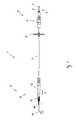
- FIG. 1a particular embodiment of a flexible catheter 1 of the type proposed here is shown schematically.
- the catheter 1comprises a flexible drive shaft 2, of which in this figure a proximal end piece 3 can be seen protruding from a proximal coupling module 4 (self-supporting) and at the proximal end of which the drive shaft 2 has a coupling element 5 for connecting the drive shaft 2 a drive motor, cf.
- FIG. 2The catheter 1 also comprises a flexible sleeve 6 surrounding the drive shaft 2 and radially supporting it (not shown here, but see FIGS.
- the catheter 1comprises at a distal end 9 of the catheter Catheter 1, a pump head 10 with a pump housing 11, a distal to the pump housing 11 arranged end housing 13 for the drive shaft 2 and a proximally to the pump housing 11 adjacent outflow hose 12 (in FIG. 1 are running within the outflow hose 12 elements shown in phantom).
- a support member 14is arranged distally in the form of a so-called pigtail tip.
- the catheter 1has a lock 15. Its function is to compress the pump head 10 when it is drawn into the lock 15 radially.
- the pump head 10can then be guided, for example, through an introducer sheath (not shown in the figures) and implanted therethrough.
- the introducer sheathmay, for example, be fixed to a puncture site on or in the body of a patient so as to likewise support the catheter 1 at this point.
- the document EP2399639 A1 directedmay also refer to the document EP2399639 A1 directed.
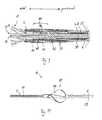
- FIG. 2For example, as part of a blood pump assembly 16, this catheter is shown in a highly implanted state in an implanted state. Shown is a use or application of the catheter 1 and the blood pump assembly 16, in the drive shaft 2 of the catheter 1 via the coupling element 5 rotatably (but axially displaceable, see description FIG. 12 ) is connected to a corresponding coupling element 17 of a drive motor 18 of the blood pump assembly 1.
- the drive motor 18is configured to operate at high speeds in a range between 10,000 and 40,000 revolutions per minute Minute to produce.
- a pump rotor 20 functional elementrotatably connected.
- the pump rotor 20is disposed within the pump housing 11, which is formed in this embodiment, that it can be transferred from a radially expanded state to a radially compressed state. This can be done for example by means of the lock 15 or the above-mentioned introducer sheath, preferably by the pump housing 11 is at least partially pulled into the respective sheath under application of a (pull) force acting on the proximal end 8 of the catheter and thereby along a transverse is compressed to the longitudinal direction extending radial direction. By a reverse force, the pump housing 11 can be converted accordingly from the compressed to the expanded state. Also at this point is on the publication EP2399639 A1 , referenced.
- the catheter 1is inserted with its distal end 9 first through a puncture site 21 in the body of a patient in the femoral artery 22 and inserted along this over the aortic arch 23 in the left ventricle 24 of the heart 25.
- the pump housing 11is positioned in the left ventricle such that it is supported by the support member 14 against an inner wall 26 of the left ventricle 24 and the exit tube 12 extends through the aortic valves 27 into the aorta 28.
- the blood driven by the pump rotor 20 and flowing out of the pump housingis thus guided through the outflow tube 12 into the aorta 28.
- the proximal end 8 of the catheter 1, the proximal end 3 of the drive shaft 2 and the drive motor 18are arranged outside the body.
- an overall (axial) length of the catheter and an overall (axial) length of the drive shaft 2are approximately 150 cm (corresponding to an implantable length of approximately 140 cm), an overall (axial) length of the distal end 9 of FIG Catheter (including pump head 12 and support member 14) is about 13.5 cm.
- the flexibility or the flexibility of the catheter 1, ie in particular the drive shaft 2, the sleeve 6 and the jacket 7are so large that the catheter 1, as described above, can be implanted and operated.
- these componentsat least within the distal end 9 of the catheter with the typical radius of curvature R of the aortic arch 23 of approximately 30 mm, these components must be able to be elastically curved by 180 °, as in FIG FIG. 2 shown, without causing plastic deformation in particular of the drive shaft 2.
- FIGS. 4 and 6configured as a hollow shaft and has a cavity 29 extending axially within the drive shaft 2.
- the cavity 29extends along the entire length of the drive shaft 2. At least within the approximately 4.5 cm long distal end portion 19 of the drive shaft, however, this cavity 29 is completely filled with a reinforcing material 30, a so-called soul, see FIGS. 6 . 9 and 10 and the related description below, to achieve sufficient rigidity and vibration stability of the drive shaft 2 and the distal end portion 19 of the drive shaft.
- the drive shaft 2has a plurality of coaxial turns 31, 32, which rotate the cavity 29 of the drive shaft 2 helically to convert torsional and bending stresses in axial tensile or compressive stresses.
- the windings 31, 32are arranged in two coaxial layers 33, 34 or layers of the drive shaft 2, wherein the windings 31 within the inner layer 33 are arranged koradial (with the same winding radius) and the windings 32 are arranged inside the outer layer koradial.
- the turns of the inner layer 33have an opposite winding direction with respect to the turns of the outer layer 34, so that tensile and compressive stresses between the layers can be compensated.
- the drive shaft in the inner layer 33comprises four coaxially and corradially wound around the cavity 29 wires 35 and in the outer layer 34 five coaxial and corradial wound around the cavity wires, with axially adjacent turns 31 of the inner layer touching each other, However, axially adjacent turns 32 of the outer layer do not touch each other (each with no curvature of the drive shaft), but have an axial distance of about 0.03 mm.
- An outer diameter d a of Drive shaftis in the present example about 0.88 mm and an inner diameter d i about 0.28 mm.
- the wireshave a circular cross section with a diameter of about 0.15 mm.
- the direction of rotation of the turns 36 of the outer layer 34 of the intended direction of rotation of the drive shaft 2 for (proximal) blood deliveryis opposite.
- this direction of rotationcorresponds to the clockwise direction (defined for a viewing direction from the proximal to the distal end of the drive shaft).
- the torque to be transmitted in this casecauses the outer layer to tend to contract and shorten. Since the inner layer 33 has an opposite tendency due to its opposite winding direction, these tendencies are advantageously largely offset. In principle, this mutual compensation can also be achieved in the opposite case, namely when the winding sense of the outer layer corresponds to the direction of rotation and the sense of winding of the inner layer of the direction of rotation of the drive shaft is opposite.
- the wires 35, 36 of the drive shaft 2are made entirely of an alloy containing as alloying parts about 35% by weight of nickel, about 35% by weight of cobalt, about 20% by weight of chromium and about 10% by weight of molybdenum. These alloy proportions of the alloy can also be greater or less by up to 3% by weight or in each case by up to 2% greater or less. In particular, the alloy in this example 35NLT ®, but it could just as well also be MP35N ®. The proportion by weight of iron in the wires is thus less than 1% by weight and the proportion by weight of titanium is less than 0.1% by weight.
- the alloy and windings 31, 32 of the drive shafthave been manufactured using high-temperature strain hardening and strain hardening.
- a non-rusting, austenitic steelaccording to the material number DIN 1.4310 is selected in this example (X10CrNi18-8).
- any other materialcould be chosen as the reinforcing material that meets the requirements specified above in this context.
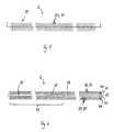
- the sleeve 6is shown, which is configured in the example shown as a bearing spiral with a plurality of turns 37, wherein the windings 37 of the bearing spiral rotate the drive shaft 2 in the axial direction in the manner of a helix.
- the bearing spiralis given by a wound flat band 38.
- the ribbon 38has a width B measured by a factor of about 6 (measured axially) as the thickness D (measured radially).
- the width B of the turns 37is 0.6 mm and the thickness D of the turns 37 0.1 mm.
- the turns 37are also as slight as possible relative to the longitudinal axis L of the bearing spiral (in the straight state without curvature of the bearing spiral) angled or tilted, possibly less than 5 °, so that an inner surface 39 of the sleeve 6 formed by the turns 37 is as cylindrical as possible or forms cylindrical surfaces as possible.
- the lateral edges 54 of the flat stripare preferably as rounded as possible with a radius of curvature r k of about 0.04 mm.
- the radius of curvature r k of the edges 54is more than 0.04 mm.
- an inner diameter D i of the sleeve 6is about 1 mm and an outer diameter D A of the sleeve 6 is about 1.2 mm and a pitch of about 0.7.
- the sleeve 6 or, the ribbon 38is in this example, of the same alloy as the wires 35, 36 of the drive shaft 2, that is present from 35NLT ®, but could also be a different one of said materials for this purpose be made.
- FIG. 9is a longitudinal section through the in FIG. 1 Shown schematically with Y designated axial portion of the catheter 1.
- the catheter 1comprises bearing elements 40, 41, 42 arranged proximal to the pump rotor 20 for the radial and axial bearing of the drive shaft 2.
- bearing elements 40, 41, 42The arrangement and configuration of these bearing elements 40, 41, 42 is on the in FIG. 10 shown pump rotor 20 of the catheter 1 tuned.
- This pump rotor 20has a blading 43, whose configuration, configuration and angle of attack for conveying the blood to the proximal (proximal conveying direction, ie in the direction of the proximal end of the catheter) is set up.
- the bearing elements 40 and 41form a pump bearing 20 proximally arranged thrust bearing 44.
- the bearing member 41is a first thrust bearing member of the thrust bearing 44 and the bearing member 40 is a second thrust bearing member of the thrust bearing 44.
- the thrust bearing 44is due to the configuration and arrangement of these (axial) bearing elements 40, 41 adapted to counteract a distally directed axial displacement (caused by the proximal conveying action of the pump rotor 20) of the drive shaft 2. In this way, during operation of the blood pump arrangement, axial bearing forces act primarily as tensile forces on the drive shaft 2.
- the (first) bearing element 41is preferably designed annular and rotationally fixed, for example by crimping, connected to the drive shaft 22.
- the bearing elements 40, 41have mutually facing, annular sliding surfaces 45 and 46, which block an axial displacement of the drive shaft 2 in a mutual contact in the distal direction.
- the sliding surface 46 of the (first) bearing element 41has a profiling, see FIGS. 13 and 14 and the associated description below, whereby the formation of a stable lubricating film between the two sliding surfaces 45, 46 favors and an embodiment of the thrust bearing 44 is made possible in principle as a hydrodynamic sliding bearing.
- the lubricating film or the hydrodynamic bearingis formed in this example with the lubricating medium described below.
- the bearing element 40is also, as well as the bearing element 42, designed as a radial bearing element with each one of the drive shaft 2 facing, cylindrically configured and coaxial with the axis of rotation of the drive shaft 2 arranged sliding surface.
- the drive shaft 2in the axial sections in which it exits distally from the sleeve 6 and is supported by the bearing elements 40, 41, 42, stiffened by the reinforcing material 30.
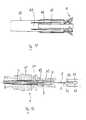
- FIG. 11is a longitudinal section through the in FIG. 1 Shown schematically with the reference numeral Z axial portion of the catheter 1, which in particular includes the distal to the pump housing 11 adjacent end housing 13.
- the end housing 13is tubular in shape and in a distal bearing channel 47 and a bearing member 47 disposed therein for radially supporting the distal end portion 19 of the drive shaft 2.
- the cavity 47is dimensioned in particular sufficiently large to allow axial compensating movements of the drive shaft 2.
- FIG. 12is a longitudinal section through the in FIG. 1 shown proximal coupling module 4, which has a proximal bearing channel 49 for the proximal end 3 of the drive shaft 2, wherein the proximal end 3 of the drive shaft 2 passes through the bearing channel 49 axially and protrudes axially from the proximal coupling module 4.
- a bearing element 50 for radial stabilization or storage of the proximal end piece 3 of the drive shaft 2is arranged in the bearing channel 49.
- the sleeve 6extends axially through this bearing element 50 through to its proximal end.
- the bearing element 50 in this embodimenthas the function of radially stabilizing and supporting the sleeve 6 from the outside.
- the sleeve 60does not pass through the bearing element 50, but ends (coming from distally) at the distal end of the bearing element 50.
- the bearing element 50is configured, for example, as a sliding bearing or as a roller bearing.
- the distal end portion 19 of the drive shaft and the proximal end piece 3may be stiffened by the reinforcing material 30, in particular in the axial sections in which the drive shaft exits from the bearing channel 49 and is supported by the bearing element 50.
- the bearing members 40, 41, 42, 48 and 50are preferably each made of zirconia, preferably in the yttrium stabilized form, of alumina, of a ceramic or of the same material as the wires 35, 36 of the drive shaft 2.
- the coupling housing 4also has channels 51 for supplying and discharging a lubricating medium, wherein the channels with the bearing channel 49 and with a gap between the sleeve 6 and the drive shaft 2 is fluidly connected.
- a gap between the drive shaft and the sleeveis filled with a lubricating medium which is biocompatible and preferably also physiological.
- the lubricating mediumis biocompatible and in this example is distilled water, but it could also be, for example, a physiological saline solution or a glucose solution.
- the coupling element 5 of the drive shaft 2is designed to be as rigid as possible and connected to the proximal end piece 3 of the drive shaft 2 such that it is rotationally, tension- and pressure-resistant.
- the coupling element 5 of the drive shaft and the Coupling element 17 of the drive motor 18, which is configured in this example as a receptacle for the coupling element 5,have to form a rotationally fixed but axially displaceable connection with each other corresponding axial sliding surfaces 52 and 53, respectively. These run parallel to the longitudinal axis of the respective coupling element 5 or 17 and do not change their shape along the longitudinal axis of the respective coupling element 5 or 17.
- the coupling element 5 of the drive axle 2is a square.
- the jacket 7may consist completely or at least partially of a plastic, for example of a polyurethane, in particular of a carbothane or a urethane.
- the sheathhas a metal reinforcement on, which can for example consist of the proposed alloy for the drive shaft, so, for example, MP35N ®.
- FIGS. 13 and 14each show a schematic perspective view of an embodiment of the in FIG. 9
- the sliding surface 46 of the respective bearing element 41has a profiling 55, so that the two sliding surfaces 45, 46 form a hydrodynamic sliding bearing in interaction with the lubricating medium, whereby an abrasion volume of the sliding surfaces 45, 46 or the two Bearing elements 40, 41 can be significantly reduced.
- the profiling 55 of the respective sliding surface 46comprises a plurality of elevations 56 and recesses 57.
- FIG. 13In the example shown, there are exactly 12 elevations and 12 wells in which FIG.
- elevations 56 and depressions 57are distributed uniformly along a circumferential or circumferential direction (indicated in the figures by an arrow indicated by U) of the respective sliding surface 46 distributed over this sliding surface 46 and configured as an alternating sequence of ribs and grooves.
- ribs and grooveseach extend from one of the drive shaft 2 facing inner edge 58 of the respective sliding surface 46 to a drive shaft 2 facing away from the outer edge 59 of the respective sliding surface 46.
- the ribseach have a height (This corresponds to the depth of each laterally adjacent groove) of about 0.06 mm and a mean width (measured in the circumferential direction U) of about 0.2 mm.
- Umean width
- the elevations 55 designed as ribseach have a maximum height of approximately 0.1 mm, each elevation having a preliminary surface 60 and a trailing surface 61, wherein the precut surface 60 rotates in the intended direction along the circumferential direction when the bearing element 41 rotates U (clockwise in a viewing direction to the distal end 9 of the catheter 1) with respect to the Nachfauf requirements 61 progresses.
- This leading surface 60is inclined or beveled with respect to the longitudinal axis of the bearing element 41 such that the elevation 56 narrows upward (ie in the direction of the opposite sliding surface 45 of the second bearing element 40, in the present example in the distal direction) or rejuvenated.
- inclined or bevelled lead surfaces 60in principle, ie in any other exemplary embodiments of profilings of the bearing element 41, a more uniform bow wave formation of the lubricating medium can be achieved and thus a more stable lubricating film can be formed.
- each of the elevations 56has an average width (measured in the circumferential direction U) of approximately 0.3 mm, the width of the elevation 56 increasing in the radial direction.
- An average width (measured in the circumferential direction U) of the grooves 57 in this exampleis about 0.1 mm, whereby the width of the grooves increases radially outward.
- FIGS. 13 and 14 shown embodimentscan be produced for example by means of a (cutting) laser.
Landscapes
- Health & Medical Sciences (AREA)
- Engineering & Computer Science (AREA)
- Heart & Thoracic Surgery (AREA)
- Mechanical Engineering (AREA)
- Life Sciences & Earth Sciences (AREA)
- Animal Behavior & Ethology (AREA)
- Veterinary Medicine (AREA)
- Public Health (AREA)
- General Health & Medical Sciences (AREA)
- Biomedical Technology (AREA)
- Cardiology (AREA)
- Anesthesiology (AREA)
- Hematology (AREA)
- General Engineering & Computer Science (AREA)
- Oral & Maxillofacial Surgery (AREA)
- Vascular Medicine (AREA)
- Inorganic Chemistry (AREA)
- Epidemiology (AREA)
- Chemical & Material Sciences (AREA)
- Physics & Mathematics (AREA)
- Fluid Mechanics (AREA)
- External Artificial Organs (AREA)
- Media Introduction/Drainage Providing Device (AREA)
- Surgery (AREA)
- Nuclear Medicine, Radiotherapy & Molecular Imaging (AREA)
- Medical Informatics (AREA)
- Molecular Biology (AREA)
- Infusion, Injection, And Reservoir Apparatuses (AREA)
- Shafts, Cranks, Connecting Bars, And Related Bearings (AREA)
- Transplantation (AREA)
Abstract
Translated fromGermanDescription
Translated fromGermanDie Erfindung betrifft einen flexiblen Katheter mit einer biegsamen Antriebswelle gemäß dem Oberbegriff des Hauptanspruchs sowie eine Blutpumpeanordnung mit einem solchen Katheter.The invention relates to a flexible catheter with a flexible drive shaft according to the preamble of the main claim and a blood pumping arrangement with such a catheter.
Derartige Katheter werden typischerweise dazu verwendet, innerhalb eines Körpers eines Menschen oder eines Tieres ein Drehmoment oder eine Drehbewegung zu erzeugen bzw. zu übertragen. Die Antriebswelle verläuft axial entlang der Längsausdehnung des Katheters zwischen einem proximalen Ende des Katheters und einem distalen Ende des Katheters. Typischerweise ist ein proximales Ende der Antriebswelle außerhalb des Körpers mit einem Antriebsmotor verbunden, um das Drehmoment bzw. die Drehbewegung zu erzeugen und auf die Antriebswelle zu übertragen. Am distalen Ende der Antriebswelle ist typischerweise ein Drehelement bzw. Funktionselement drehfest mit der Antriebswelle verbunden, das für die jeweilige Anwendung geeignet ausgestaltet ist. Bei dem Funktionselement kann es sich beispielsweise um eine Fräse, einen Rotorablator oder um einen Pumpenrotor zur Förderung von Blut handeln.Such catheters are typically used to generate torque or rotational motion within a body of a human or animal. The drive shaft extends axially along the longitudinal extent of the catheter between a proximal end of the catheter and a distal end of the catheter. Typically, a proximal end of the drive shaft external to the body is connected to a drive motor to generate the torque and to transmit it to the drive shaft. At the distal end of the drive shaft is typically a rotary element or functional element rotatably connected to the drive shaft, which is designed for the particular application suitable. The functional element may, for example, at a tiller, a rotor aerator, or a pump rotor for pumping blood.
Für viele Anwendungen ist es erforderlich, den Katheter entlang eines gewundenen Pfades durch den Körper zu führen, beispielsweise entlang bzw. innerhalb von Blutgefäßen, um das distale Ende des Katheters an einer gewünschten Stelle innerhalb des Körpers, beispielsweise innerhalb einer Herzkammer, für die Dauer der jeweiligen Anwendung zu positionieren. Neben der hierfür erforderlichen Biegsamkeit und Flexibilität des Katheters müssen in der Regel noch weitere Kriterien erfüllt sein. Beispielsweise ist es in manchen Anwendungen erforderlich, dass mit der Antriebswelle Drehbewegungen mit einer sehr hohen Drehzahl erzeugt bzw. übertragen werden, beispielsweise kann die erforderliche Drehzahl mehr als 10.000, mehr als 20.000 oder sogar mehr als 30.000 Umdrehungen pro Minute betragen, wie beispielsweise im bereits genannten Fall der Blutförderung. In Fällen, in denen die Drehbewegung über einen längeren Zeitraum, also für mehrere Stunden, Tage oder sogar Wochen erzeugt werden muss, wie dies ebenfalls bei der Blutförderung der Fall sein kann, werden außerdem besonders hohe Anforderungen an die mechanische und an die chemische Belastbarkeit des Katheters gestellt, insbesondere an die Antriebswelle. Materialermüdung und Schädigungsprozesse an der Antriebswelle und an anderen Komponenten des Katheters sollten möglichst langsam und außerdem möglichst auf vorhersehbare und kontrollierbare Weise voranschreiten. In kritischen Anwendungen, wie beispielsweise der Blutförderung, müssen Risse und Brüche der Antriebswelle im Betrieb mit möglichst großer Sicherheit ausgeschlossen werden können.For many applications, it is necessary to guide the catheter along a tortuous path through the body, for example, along or within blood vessels, around the distal end of the catheter at a desired location within the body, such as within a heart chamber, for the duration of the catheter respective application. In addition to the necessary flexibility and flexibility of the catheter further criteria must be fulfilled in the rule. For example, in some applications it is required that rotational motions be generated at a very high speed with the drive shaft, for example, the required speed may be more than 10,000, more than 20,000 or even more than 30,000 rpm, such as in the already called case of blood promotion. In cases where the rotational movement over a longer period, so for several hours, days or even weeks must be generated, as may also be the case with the blood promotion, also particularly high demands on the mechanical and chemical resistance of the Catheter placed, in particular to the drive shaft. Material fatigue and damage to the drive shaft and other components of the catheter should proceed as slowly as possible and, if possible, in a predictable and controllable manner. In critical applications, such as blood delivery, cracks and fractures of the drive shaft must be excluded in operation with the greatest possible security.
Es ist somit die Aufgabe der vorliegenden Erfindung, einen flexiblen Katheter mit einer biegsamen Antriebswelle vorzuschlagen, der möglichst sicher ist und sich möglichst auch für einen Dauerbetrieb bei hohen Drehzahlen eignet. Außerdem ist eine Blutpumpenanordnung vorzuschlagen, die ebenfalls möglichst sicher ist und sich möglichst auch für einen Dauerbetrieb bei hohen Drehzahlen eignet.It is therefore the object of the present invention to provide a flexible catheter with a flexible drive shaft, which is as safe as possible and is also suitable for continuous operation at high speeds as possible. In addition, a blood pump arrangement is to be proposed, which is also as safe as possible and is also suitable for continuous operation at high speeds as possible.
Diese Aufgabe wird gelöst durch ein Katheter gemäß dem Hauptanspruch sowie durch eine Blutpumpenanordnung gemäß Anspruch 20. Bevorzugte Ausführungsformen und Weiterentwicklungen ergeben sich mit den abhängigen Ansprüchen.This object is achieved by a catheter according to the main claim as well as by a blood pump arrangement according to
Wie im Folgenden detailliert beschrieben wird, offenbart diese Patentanmeldung mehrere Aspekte, wobei jeder dieser Aspekte ein Teil einer zusammenhängenden Erfindung ist. Andererseits stellt jeder der Aspekte auch für sich genommen bereits eine eigenständige Erfindung dar. Die Aspekte können also unabhängig voneinander realisiert werden (und stellen jeweils für sich genommen besondere Weiterentwicklungen eines gattungsgemäßen Katheters gemäß dem Oberbegriff des Hauptanspruchs dar) und können außerdem beliebig miteinander kombiniert werden, um einen gattungsgemäßen Katheter bzw. eine Blutpumpenanordnung mit einem gattungsgemäßen Katheter synergetisch zu verbessern. So kann beispielsweise ein gattungsgemäßer Katheter gemäß einem dieser Aspekte ausgestaltet sein und kann gleichzeitig auch gemäß einem (oder mehreren) weiteren Aspekt(en) ausgestaltet sein. Dieser Katheter ist dann eine besonders vorteilhafte Ausführungsform eines Katheters gemäß dem erstgenannten Aspekt. Jeder der Aspekte ermöglicht somit auch eine Weiterentwicklung jedes anderen Aspektes.As will be described in detail below, this patent application discloses several aspects, each of which is part of a cohesive invention. On the other hand, each of the aspects taken alone constitutes an independent invention. Thus, the aspects can be realized independently of each other (and in each case constitute particular further developments of a generic catheter according to the preamble of the main claim) and can also be combined with each other arbitrarily, to synergistically improve a generic catheter or a blood pump assembly with a generic catheter. For example, a generic catheter may be configured according to one of these aspects, and may also be configured according to one (or more) further aspect (s) at the same time. This catheter is then a particularly advantageous embodiment of a catheter according to the first aspect. Each of the aspects thus enables a further development of every other aspect.
Der erste dieser Aspekte betrifft das Material der Antriebswelle, der zweite Aspekt die geometrische Ausgestaltung der Antriebswelle, der dritte Aspekt die Ausgestaltung der Hülse, der vierte Aspekt die Verbindung zwischen der Antriebswelle und dem Antriebsmotor, der fünfte Aspekt die Lagerung der Antriebswelle und der sechste Aspekt ein Schmiermedium für die Antriebswelle. Jeder dieser Aspekte trägt zur Verbesserung der Belastbarkeit und der Sicherheit des Katheters bzw. der Blutpumpenanordnung bei.The first of these aspects relates to the material of the drive shaft, the second aspect relates to the geometric design of the drive shaft, the third aspect of the design of the sleeve, the fourth aspect of the connection between the drive shaft and the drive motor, the fifth aspect, the support of the drive shaft and the sixth aspect a lubricant for the drive shaft. Each of these aspects contributes to improving the resilience and safety of the catheter or blood pump assembly.
Ein gattungsgemäßer flexibler Katheter umfasst demnach eine Antriebswelle, eine die Antriebswelle umgebende Hülse und einen die Antriebswelle und die Hülse umgebenden Mantel, wobei die Antriebswelle, die Hülse und der Mantel biegsam sind. An einem proximalen Ende der Antriebswelle weist die Antriebswelle ein Kupplungselement bzw. einen Kupplungskopf auf zum Verbinden der Antriebswelle mit einem Antriebsmotor.A generic flexible catheter thus comprises a drive shaft, a sleeve surrounding the drive shaft and a jacket surrounding the drive shaft and the sleeve, wherein the drive shaft, the sleeve and the sheath are flexible. At a proximal end of the drive shaft, the drive shaft has a coupling element or a coupling head for connecting the drive shaft to a drive motor.
Typischerweise beträgt die (axiale) Gesamtlänge des Katheters zwischen 50 cm und 200 cm, in der Regel liegt die Gesamtlänge in einem Bereich zwischen 80 cm und 150 cm. Typischerweise liegen die (axialen) Gesamtlängen der Antriebswelle, der Hülse und des Mantels ebenfalls jeweils innerhalb eines dieser Bereiche. Die Flexibilität bzw. die Biegsamkeit des Katheters, also insbesondere der Antriebswelle, der Hülse und des Mantels, sollen ausreichend sein, um den Katheter mit einem Krümmungsradius in einem Bereich zwischen 20 mm und 40 mm, vorzugsweise in einem Bereich zwischen 25 mm und 35 mm, insbesondere von etwa 30 mm elastisch krümmen zu können. Bei einer solchen Krümmung sollen sich insbesondere die Antriebswelle und die Hülse möglichst nur elastisch verformen, es soll also zu möglichst keinen bleibenden (plastischen) Verformungen oder Veränderungen der Antriebswelle oder der Hülse kommen. Insbesondere soll eine solche elastische Krümmung mit dem genannten Krümmungsradius auch bei einer etwa U-förmigen Krümmung des Katheters von etwa 180° möglich sein, bei der der Katheter also beispielsweise entlang eines axialen Abschnitts des Katheters mit einer Länge von etwa (je nach Krümmungsradius) 80 mm bis 150 mm, typischerweise von etwa 100 mm bis 120 mm, durchgängig gekrümmt ist. Derartige Krümmungen des Katheters treten beispielsweise dann auf, wenn der Katheter durch den Aortenbogen in die linke Herzkammer verläuft.Typically, the (axial) total length of the catheter is between 50 cm and 200 cm, as a rule, the total length is in a range between 80 cm and 150 cm. Typically, the (axial) total lengths of the drive shaft, the sleeve and the sheath also within each of these areas. The flexibility of the catheter, that is, in particular the drive shaft, the sleeve and the sheath, should be sufficient to allow the catheter to have a radius of curvature in a range between 20 mm and 40 mm, preferably in a range between 25 mm and 35 mm , in particular of about 30 mm to bend elastically. In such a curvature, in particular, the drive shaft and the sleeve should deform as elastically as possible, so it should come to as no permanent (plastic) deformations or changes in the drive shaft or the sleeve. In particular, such an elastic curvature should be possible with the said radius of curvature even with an approximately U-shaped curvature of the catheter of about 180 °, for example, along an axial portion of the catheter with a length of about (depending on the radius of curvature) 80th mm to 150 mm, typically from about 100 mm to 120 mm, is continuously curved. Such bends of the catheter occur, for example, when the catheter passes through the aortic arch in the left ventricle.
In vielen Fällen ist es nicht erforderlich, dass der Katheter entlang seiner gesamten axialen Längsausdehnung eine derartige Flexibilität aufweist. Es kann bereits ausreichend sein, dass dies in einem bestimmten axialen Abschnitt (oder mehreren axialen Abschnitten) gegeben ist. Oftmals, wie im Fall der Blutförderung, beispielsweise wenn ein distales Ende des Katheters in einer Herzkammer platziert werden muss, weist zumindest ein distales Endstück oder ein distales Teilstück des Katheters eine derartige Flexibilität auf. Dieses distale Endstück oder Teilstück kann beispielsweise eine axiale Länge in einem der oben genannten Längenbereiche aufweisen.In many cases, the catheter is not required to have such flexibility along its entire axial length. It may already be sufficient that this is given in a certain axial section (or several axial sections). Often, as in the case of blood delivery, for example, when a distal end of the catheter must be placed in a ventricle, at least one distal end or portion of the catheter has such flexibility. This distal end piece or section may, for example, have an axial length in one of the above-mentioned length ranges.
Wie weiter unten näher beschrieben wird, darf in manchen Fällen die Biegsamkeit und Flexibilität des Katheters bzw. der Antriebswelle auch nicht zu groß werden, insbesondere in solchen axialen Abschnitten der Antriebswelle, die distal oder proximal außerhalb der Hülse verlaufen oder aus der Hülse austreten, so dass in zumindest einem dieser Abschnitte zu einem bestimmten Grad eine bereichsweise Versteifung der Antriebswelle vorteilhaft oder, je nach Anforderungen der jeweiligen Anwendung, sogar erforderlich sein kann. Gemäß dem ersten Aspekt der Erfindung kann die Antriebswelle des Katheters vollständig oder zumindest bereichsweise aus einer Legierung bestehen, die zu jeweils mindestens 10% Gewichtsanteil Chrom, Nickel und Cobalt beinhaltet. Vorzugsweise beinhaltet die Legierung zu mindestens 30% Gewichtsanteil Nickel, vorzugsweise aber nicht mehr als 40% Gewichtsanteil Nickel. Vorzugsweise beinhaltet die Legierung zu mindestens 30% Gewichtsanteil Cobalt, vorzugsweise aber nicht mehr als 40% Gewichtsanteil Cobalt. Vorzugsweise beinhaltet die Legierung zu 15% Gewichtsanteil Chrom, vorzugsweise aber nicht mehr als 25% Gewichtsanteil Chrom. Die Legierung beinhaltet vorzugsweise außerdem Molybdän, vorzugsweise mindestens 5% Gewichtsanteil, vorzugsweise aber nicht mehr als 15% Gewichtsanteil Molybdän.As will be described in more detail below, in some cases, the flexibility and flexibility of the catheter or the drive shaft may not be too large, especially in such axial portions of the drive shaft, which extend distally or proximally outside the sleeve or exit from the sleeve, so that in at least one of these sections to a certain extent a partial stiffening of the drive shaft advantageous or, depending on the requirements of the particular application, may even be required. According to the first aspect of the invention, the drive shaft of the catheter may consist entirely or at least partially of an alloy which contains at least 10% by weight each of chromium, nickel and cobalt. Preferably, the alloy contains at least 30% by weight nickel, but preferably not more than 40% by weight nickel. Preferably, the alloy contains at least 30% by weight of cobalt, but preferably not more than 40% by weight of cobalt. Preferably, the alloy comprises 15% by weight chromium, but preferably not more than 25% by weight chromium. The alloy preferably further contains molybdenum, preferably at least 5% by weight, but preferably not more than 15% by weight of molybdenum.
Beispielsweise kann die Legierung als Legierungsanteile etwa 35% Gewichtsanteil Nickel, etwa 35% Gewichtsanteil Cobalt, etwa 20% Gewichtsanteil Chrom und etwa 10% Gewichtanteil Molybdän enthalten. Diese Legierungsanteile der Legierung können jeweils auch um bis zu 3% Gewichtsanteile größer oder geringer sein oder jeweils um bis zu 2% größer oder geringer sein. Die Legierungsanteile dieser Elemente können den Legierungsanteilen dieser Elemente in der Legierung MP35N® oder den Legierungsanteilen dieser Elemente in der Legierung 35NLT® entsprechen oder hiervon jeweils um bis zu 2% Gewichtsanteile nach oben oder nach unten abweichen oder hiervon jeweils um bis zu 1% nach oben oder nach unten abweichen. Die Legierung kann außerdem weitere Legierungselemente beinhalten. Diese können entsprechend denen der Legierung MP35N® oder denen der Legierung 35NLT® ausgewählt und bemessen sein.For example, the alloy may contain as alloying portions about 35% by weight nickel, about 35% by weight cobalt, about 20% by weight chromium and about 10% by weight molybdenum. These alloy proportions of the alloy can also be greater or less by up to 3% by weight or in each case by up to 2% greater or less. The alloy proportions of these elements may correspond to the alloy proportions of these elements in the alloy MP35N® or the alloy proportions of these elements in the alloy 35NLT® or thereof in each case by up to 2% by weight of upward or downward vary or thereof in each case up to 1% upwards or deviate downwards. The alloy may also include other alloying elements. These may be similar to those of MP35N alloy® or those of the alloy 35NLT® selected and sized.
Vorzugsweise handelt es sich bei der Legierung um MP35N® oder 35NLT® oder ist auf entsprechende (oder gleiche) Weise, d.h. mit entsprechenden (oder gleichen) Verfahrensschritten und mit entsprechenden (oder gleichen) Verfahrensparametern, hergestellt worden wie MP35N® bzw. wie 35NLT®. Beispielsweise kann vorgesehen sein, dass die Legierung der Antriebswelle bzw. die Antriebswelle als Ganzes kaltverfestigt ist oder durch Anwendung einer (Hoch-)Kaltverformung oder Kaltverfestigung hergestellt bzw. geformt worden ist.Preferably, the alloy is MP35N® or 35NLT® or at corresponding (or identical) manner, has been ie produced with corresponding (or the same) method steps and with the corresponding (or identical) process parameters such as MP35N® or as 35NLT® , For example, it can be provided that the alloy of the drive shaft or the drive shaft as a whole is work hardened or has been produced or formed by application of (high) cold working or strain hardening.
Eine Antriebswelle die vollständig oder zumindest bereichsweise aus einer solchen Legierung besteht, eignet sich auch für Anwendungen bei sehr hohen Drehzahlen und langem Dauerbetrieb, so dass es mit einer solchen Antriebswelle auch möglich ist, die eingangsgenannten Drehzahlbereiche für eine längere Zeitdauer aufrechtzuerhalten. Typischerweise sind die Drehmomente, die solch hohen Drehzahlen mittels der Antriebswelle übertragen, jedoch relativ gering, insbesondere bei der Blutförderung. Auch wenn die Verwendung der Legierungen MP35N® bzw. wie 35NLT® aufgrund ihrer Belastbarkeit und ihres Korrosionswiderstandes beispielsweise für verschiedene medizinische Instrumente, wie beispielsweise ein Stylet, bekannt sein mag, überrascht ihre Eignung für biegsame Antriebswellen aufgrund der beschriebenen speziellen Anforderungen, insbesondere bei hoher Drehzahl, langer Betriebsdauer und starker Krümmung, insbesondere vor dem Hintergrund, dass für die Anwendung als Blutpumpe durchaus mehr als 500 000 000 vollständige Lastwechsel in Extremfällen mehr als 1 000 000 000 Lastwechsel auftreten können.A drive shaft which completely or at least partially from a Such alloy is also suitable for applications at very high speeds and long continuous operation, so that it is also possible with such a drive shaft to maintain the aforementioned speed ranges for a longer period of time. Typically, however, the torques that transmit such high speeds by means of the drive shaft are relatively low, especially in blood delivery. Although the use of alloys MP35N® or how 35NLT® may be, for example, for various medical instruments such as a stylet, known for their resilience and their corrosion resistance, surprised their suitability for flexible drive shafts due to the described specific requirements, particularly at high speed , long service life and high curvature, especially in view of the fact that for use as a blood pump more than 500 000 000 full load changes can occur in extreme cases more than 1 000 000 000 load changes.
Bislang wurden für die Antriebswelle, insbesondere für Blutpumpen, Legierungen mit einem relativ hohen Eisenanteil oder Titananteil verwendet, um eine hohe Belastbarkeit zu erzielen. Wie sich jedoch im Rahmen der vorliegenden Erfindung herausgestellt hat, kann bzw. sollte sogar möglichst auf einen hohen Anteil von Eisen und Titan verzichtet werden, um einen Dauerbetrieb bei hohen Drehzahlen zu ermöglichen. Der Gewichtsanteil an Eisen und Titan ist vorzugsweise sogar relativ gering gewählt, vorzugsweise jeweils weniger als 2% Gewichtsanteil, oder sogar jeweils weniger als 1% Gewichtsanteil. Im Prinzip kann auf Eisen und Titan als Legierungsanteile völlig verzichtet werden, entsprechend einem Gewichtsanteil von jeweils weniger als 0,1%.Until now, alloys with a relatively high iron content or titanium content have been used for the drive shaft, in particular for blood pumps, in order to achieve a high load capacity. However, as has been found in the context of the present invention, or even should be possible as far as possible to dispense with a high proportion of iron and titanium in order to allow continuous operation at high speeds. The proportion by weight of iron and titanium is preferably even chosen to be relatively low, preferably in each case less than 2% by weight, or even in each case less than 1% by weight. In principle, can be completely dispensed with iron and titanium as alloying shares, corresponding to a weight content of less than 0.1%.
Gemäß dem ersten Aspekt kann die Antriebswelle vollständig oder zumindest bereichsweise aus einer Legierung bestehen, die einen Gewichtsanteil von Eisen aufweist, der weniger als 2% beträgt oder vorzugsweise weniger als 1% beträgt oder besonders bevorzugt weniger als 0,1% beträgt. Gemäß dem ersten Aspekt kann die Antriebswelle vollständig oder zumindest bereichsweise aus einer Legierung bestehen, die einen Gewichtsanteil von Titan aufweist, der weniger als 2% beträgt oder vorzugsweise weniger als 1% beträgt oder besonders bevorzugt weniger als 0,1% beträgt.According to the first aspect, the drive shaft can consist entirely or at least partially of an alloy which has a weight fraction of iron which is less than 2% or preferably less than 1% or particularly preferably less than 0.1%. According to the first aspect, the drive shaft can consist entirely or at least partially of an alloy which has a weight proportion of titanium which is less than 2% or preferably less than 1% or particularly preferably less than 0.1%.
Vorzugsweise bestehen die Antriebswelle, die Hülse, der Mantel und/oder ggf. vorhandene Lagerelemente möglichst aus biokompatiblen Materialien oder besteht zumindest eine Außenflächen der jeweiligen Komponente aus einem biokompatiblen Material.Preferably, there are the drive shaft, the sleeve, the jacket and / or possibly existing bearing elements as possible of biocompatible materials or at least one outer surfaces of the respective component consists of a biocompatible material.
Entsprechend dem zweiten Aspekt der Erfindung kann die Antriebswelle einen sich innerhalb der Antriebswelle axial erstreckenden Hohlraum aufweisen. Bei der Antriebswelle kann es sich dann also um eine Hohlwelle handeln. Der Hohlraum kann sich innerhalb der Antriebswelle entlang einer gesamten Längsausdehnung der Antriebswelle erstrecken. Durch den Hohlraum kann eine hohe Biegsamkeit der Antriebswelle bei gleichzeitiger relativ großer Torsionssteifheit erzielt werden. Die Biegsamkeit kann weiter gesteigert werden, wenn die Antriebswelle eine Mehrzahl bzw. eine Vielzahl koaxialer Windungen aufweist, die den Hohlraum der Antriebswelle wendelförmig umlaufen. Außerdem können durch die Windungen Torsions- und Biegespannungen in axiale Zug- bzw. in Druckspannungen umgewandelt werden, wodurch sich die Belastung der Antriebswelle reduzieren kann. Es ist außerdem möglich, dass die Windungen der Antriebswelle in zwei oder mehr koaxialen Lagen der Antriebswelle angeordnet sind. Dann haben die Windungen innerhalb verschiedener koaxialer Lagen vorzugsweise gegenläufige Wicklungsrichtungen. Auf diese Weise können sich durch Torsionsspannungen hervorgerufene Zug- und Druckspannungen zwischen den Lagen vollständig oder zumindest teilweise gegenseitig ausgleichen bzw. kompensieren. Insgesamt können so außerdem auch Biegespannungen in der Antriebswelle verringert werden.According to the second aspect of the invention, the drive shaft may have a cavity extending axially within the drive shaft. The drive shaft may then be a hollow shaft. The cavity may extend within the drive shaft along an entire longitudinal extent of the drive shaft. Through the cavity, a high flexibility of the drive shaft can be achieved while relatively high torsional stiffness. The flexibility can be further increased if the drive shaft has a plurality or a plurality of coaxial coils, which rotate the cavity of the drive shaft helically. In addition, torsional and bending stresses can be converted into axial tensile or compressive stresses by the windings, which can reduce the load on the drive shaft. It is also possible that the windings of the drive shaft are arranged in two or more coaxial layers of the drive shaft. Then, the turns within different coaxial layers preferably have opposite directions of winding. In this way, tensile and compressive stresses between the layers caused by torsional stresses can compensate each other completely or at least partially. Overall, as well as also bending stresses in the drive shaft can be reduced.
Bei den Windungen der Antriebswelle handelt es sich typischerweise um Windungen eines gewundenen Drahtes oder mehrerer entsprechend gewundener Drähte. Innerhalb jeder Lage kann die Antriebswelle genau einen oder mehrere solche Drähte umfassen, beispielsweise 1 bis 8 Drähte, vorzugsweise 4 bis 6 Drähte, besonders bevorzugte 5 Drähte. Der Draht bzw, die Drähte bestehen vorzugsweise aus der oben beschriebenen Legierung. Der Draht bzw. die Drähte haben typischerweise jeweils Durchmesser in einem Bereich von etwa 0,09 mm bis etwa 0,21 mm, vorzugweise von etwa 0,135 mm bis etwa 0,165 mm. Ein Außendurchmesser der Antriebswelle liegt typischerweise in einem Bereich von etwa 0,53 mm bis etwa 1,32 mm, vorzugsweise in einem Bereich von etwa 0,79 mm bis etwa 0,97 mm. Ein Innendurchmesser der Antriebswelle liegt typischerweise in einem Bereich von etwa 0,17 mm bis etwa 0,39 mm, vorzugsweise in einem Bereich von etwa 0,25 mm bis etwa 0,31 mm. Im Fall von zwei konzentrischen Lagen berühren sich axial benachbarte Windungen der inneren Lage gegenseitig, wohingegen axial benachbarte Windungen der äußeren Lage vorzugsweise sich gegenseitig nicht berühren (jeweils bei krümmungsfreier Ausrichtung der Antriebswelle), sondern einen axialen Abstand in einem Bereich von etwa 0,018 mm bis etwa 0,042 mm, vorzugsweise von etwa 0,027 mm bis etwa 0,033 mm, aufweisen.The windings of the drive shaft are typically windings of a coiled wire or a plurality of correspondingly wound wires. Within each layer, the drive shaft may comprise exactly one or more such wires, for example 1 to 8 wires, preferably 4 to 6 wires, most preferred 5 wires. The wire or wires are preferably made of the alloy described above. The wire (s) typically have diameters in a range from about 0.09 mm to about 0.21 mm, preferably from about 0.135 mm to about 0.165 mm. An outer diameter of the drive shaft is typically in a range of about 0.53 mm to about 1.32 mm, preferably in a range of about 0.79 mm to about 0.97 mm. An inner diameter of the drive shaft is typically in a range of about 0.17 mm about 0.39 mm, preferably in a range of about 0.25 mm to about 0.31 mm. In the case of two concentric layers, axially adjacent turns of the inner layer contact each other, whereas axially adjacent turns of the outer layer preferably do not contact each other (each with no curvature of the drive shaft) but an axial distance in a range of about 0.018 mm to about 0.042 mm, preferably from about 0.027 mm to about 0.033 mm.
Ferner kann vorgesehen sein, dass die Windungen der Antriebswelle durch Anwendung einer (Hoch-)Kaltverformung oder Kaltverfestigung hergestellt bzw. geformt worden sind, um die Elastizität und Haltbarkeit der Antriebswelle zu verbessern.Further, it may be provided that the windings of the drive shaft have been formed by use of (high) cold working or strain hardening to improve the elasticity and durability of the drive shaft.
Es ist möglich, dass der Hohlraum vollständig oder innerhalb axialer Abschnitte der Antriebswelle mit einem Verstärkungsmaterial ausgefüllt ist, um die Steifigkeit und Stabilität der Antriebswelle in dem jeweiligen axialen Abschnitt einzustellen und (ggf. bereichsweise) zu vergrößern. Wie bereits im Zusammenhang mit dem ersten Aspekt der Erfindung erläutert, ist neben einer ausreichenden Biegsamkeit der Antriebswelle gleichzeitig auch eine ausreichende Steifigkeit der Antriebswelle für einen sicheren Betrieb des Katheters, insbesondere bei hohen Drehzahlen und langer Betriebsdauer, erforderlich, beispielsweise um eine stabile Rotation der Antriebswelle zu ermögliche, insbesondere in axialen Abschnitten der Antriebswelle, die distal oder proximal außerhalb der Hülse verlaufen (distales bzw. proximales Endstück der Antriebswelle). Auf diese Weise ergänzen sich der erste und der zweite Aspekt der Erfindung auf synergetische Weise. In einer bevorzugten Ausführungsform ist demnach vorgesehen, dass ein distales Endstück der Antriebswelle und/oder ein proximales Ende bzw. Endstück der Antriebswelle versteift ist bzw. sind. Vorzugsweise weist das versteifte distale bzw. proximale Ende bzw. Endstück eine Länge zwischen 10 mm bis 60 mm auf, besonders bevorzugt eine Länge zwischen 20 mm und 50 mm. Vorzugsweise ist die Antriebswelle in solchen Bereichen versteift, in denen (zusätzlich zur Hülse oder statt bzw. an Stelle der Hülse) Lagerelemente zur axialen und/oder radialen Lagerung der Antriebswelle angeordnet sind. Vorteilhaft kann es außerdem sein, die Antriebswelle in dem Bereich zu versteifen, in denen die Antriebswelle proximal in die Hülse ein- bzw. austritt und folglich nicht in der Hülse geführt ist. Vorteilhaft kann es außerdem sein, die Antriebswelle in dem Bereich zu versteifen, in denen die Antriebswelle distal in die Hülse ein- bzw. austritt. Gerade in diesen Übergangsbereichen können durch eine Versteifung der Antriebswelle Biege- und andere Belastungen, wie beispielsweise Schwingungsbefastungen, der Antriebswelle reduziert werden.It is possible that the cavity is completely or within axial portions of the drive shaft filled with a reinforcing material to adjust the rigidity and stability of the drive shaft in the respective axial section and (possibly in areas) to increase. As already explained in connection with the first aspect of the invention, in addition to a sufficient flexibility of the drive shaft at the same time sufficient rigidity of the drive shaft for safe operation of the catheter, especially at high speeds and long service life, required, for example, a stable rotation of the drive shaft to allow, in particular in axial portions of the drive shaft, which extend distally or proximally outside of the sleeve (distal or proximal end portion of the drive shaft). In this way, the first and second aspects of the invention complement each other synergistically. In a preferred embodiment, it is accordingly provided that a distal end piece of the drive shaft and / or a proximal end or end piece of the drive shaft is stiffened or are. Preferably, the stiffened distal or proximal end or tail has a length between 10 mm to 60 mm, more preferably a length between 20 mm and 50 mm. Preferably, the drive shaft is stiffened in those areas in which (in addition to the sleeve or instead of or instead of the sleeve) bearing elements for axial and / or radial mounting of the drive shaft are arranged. It can also be advantageous to stiffen the drive shaft in the region in which the drive shaft enters and exits proximally into the sleeve and is therefore not guided in the sleeve. Advantageous it may also be to stiffen the drive shaft in the area in which the drive shaft enters or exits distally into the sleeve. Especially in these transition areas can be reduced by a stiffening of the drive shaft bending and other loads, such as Schwingungsbefastungen, the drive shaft.
Als Verstärkungsmaterialen zur Versteifung der Antriebswelle eignen sich Materialien, die sich durch eine hohe Steifigkeit einerseits und gleichzeitig durch eine verhältnismäßig hohe elastische Verformbarkeit auszeichnen. Insbesondere soll das Verstärkungsmaterial bzw. das Versteifungsmaterial sämtliche Biegungen, die das Katheter bzw. der Pumpenkopf des Katheters während der Implantation und während des Betriebs ausgesetzt ist, tolerieren. Beispielsweise kommt ein nicht rostender, austenitischer Stahl als Verstärkungsmaterial in Frage, beispielsweise ein Stahl gemäß der Werkstoffnummer DIN 1.4310.Suitable reinforcing materials for stiffening the drive shaft are materials that are characterized by a high rigidity on the one hand and at the same time by a relatively high elastic deformability. In particular, the reinforcing material or stiffening material should tolerate any bends that the catheter or pumphead of the catheter is exposed to during implantation and during operation. For example, a stainless austenitic steel is used as reinforcing material, for example a steel according to the material number DIN 1.4310.
Alternativ oder zusätzlich zu dem beschriebenen Verstärkungsmaterial kann eine entsprechende Versteifung durch (axiales und/oder radiales) Verschweißen oder Verlöten (axial bzw. radial) benachbarter der Windungen der (wendelförmigen) Antriebswelle erreicht werden. Außerdem ist es möglich, dass eine gewisse (und unter Umständen ausreichende) Versteifung der Antriebswelle durch das distale Funktionsmodul, das typischerweise drehfest auf einem Außenumfang der Antriebsachse befestigt ist, wie beispielsweise ein Pumpenrotor, erreicht werden kann.Alternatively, or in addition to the described reinforcing material, a corresponding stiffening by (axial and / or radial) welding or soldering (axially or radially) adjacent the turns of the (helical) drive shaft can be achieved. In addition, it is possible that a certain (and possibly sufficient) stiffening of the drive shaft by the distal functional module, which is typically rotatably mounted on an outer periphery of the drive axle, such as a pump rotor, can be achieved.
Gemäß dem dritten Aspekt der Erfindung kann die Hülse als eine Lagerspirale mit einer Mehrzahl von Windungen ausgestaltet sein. Die Windungen der Lagerspirale umlaufen die Antriebswelle in axialer Richtung in der Art einer Wendel. Beispielsweise kann die Lagerspirale ein aufgewickeltes Flachband sein. Das Flachband hat vorzugsweise um einen Faktor von mindestens 3, vorzugsweise um einen Faktor von 6, größere Breite (axial gemessen) als Dicke (radial gemessen). Typischerweise liegt die Breite der Windungen in einem Bereich von etwa 0,36 mm bis etwa 0,84 mm, vorzugsweise in einem Bereich von etwa 0,54 mm bis etwa 0,66 mm. Die Dicke der Windungen liegt typischerweise in einem Bereich von etwa 0,06 mm bis etwa 0,14 mm, vorzugsweise in einem Bereich von etwa 0,09 mm bis etwa 0,11 mm. Ferner liegt ein Innendurchmesser der Hülse typischerweise in einem Bereich zwischen etwa 0,6 mm und etwa 1,4 mm, vorzugsweise in einem Bereich von etwa 0,9 mm bis etwa 1,1 mm. Ein Außendurchmesser der Hülse liegt typischerweise in einem Bereich von etwa 0,72 mm bis etwa 1,68 mm, vorzugsweise in einem Bereich von etwa 1,08 mm bis etwa 1,32 mm. Eine Steigung der Lagerspirale liegt vorzugsweise in einem Bereich von etwa 0,43 bis etwa 0,98, vorzugsweise in einem Bereich von etwa 0,63 bis 0,77, wobei der Innendurchmesser der Hülse mit dem Außendurchmesser der flexiblen Antriebswelle korrespondiert, insbesondere also größer ist als der Außendurchmesser der Antriebswelle.According to the third aspect of the invention, the sleeve may be configured as a bearing coil having a plurality of turns. The turns of the bearing spiral rotate around the drive shaft in the axial direction in the manner of a helix. For example, the bearing spiral can be a wound ribbon. The ribbon preferably has a width (measured axially) as a thickness (measured radially) by a factor of at least 3, preferably by a factor of 6. Typically, the width of the turns is in a range of about 0.36 mm to about 0.84 mm, preferably in a range of about 0.54 mm to about 0.66 mm. The thickness of the windings is typically in a range of about 0.06 mm to about 0.14 mm, preferably in a range of about 0.09 mm to about 0.11 mm. Furthermore, there is a Inner diameter of the sleeve typically in a range between about 0.6 mm and about 1.4 mm, preferably in a range of about 0.9 mm to about 1.1 mm. An outer diameter of the sleeve is typically in a range of about 0.72 mm to about 1.68 mm, preferably in a range of about 1.08 mm to about 1.32 mm. A pitch of the bearing spiral is preferably in a range of about 0.43 to about 0.98, preferably in a range of about 0.63 to 0.77, wherein the inner diameter of the sleeve corresponds to the outer diameter of the flexible drive shaft, in particular larger is as the outer diameter of the drive shaft.
Vorzugsweise weist die Lagerspirale, falls sie als gewickeltes Flachband ausgestaltet ist, möglichst geringe Fertigungstoleranzen bezüglich einer (axialen) Verkippung der Windungen relativ zur Längsachse der Lagerspirale auf (im geraden Zustand ohne Krümmung der Lagerspirale). Vorzugsweise beträgt die Verkippung weniger als 10°, besonders bevorzugt weniger als 5°. Vorzugsweise bildet die Innenfläche der Hülse bzw. der Windungen der Lagerspiralen somit zylinderförmige Teilflächen aus anstelle von konischen Teilflächen (Verkippung). Eine Verkippung der Windungen zur Längsachse führt zu einer Verkleinerung der zur Verfügung stehenden Lagerfläche und zu einer größeren Druckbelastung der Antriebswelle. Vorzugsweise sind die seitlichen Kanten des Flachbandes möglichst abgerundet, um Druckspitzen auf die Antriebswelle möglichst zu vermeiden. Vorzugsweise beträgt der Krümmungsradius der Kanten 0,04 mm oder mehr.Preferably, the bearing spiral, if it is designed as a wound flat strip, the lowest possible manufacturing tolerances with respect to an (axial) tilting of the turns relative to the longitudinal axis of the bearing spiral (in the straight state without curvature of the bearing spiral). Preferably, the tilt is less than 10 °, more preferably less than 5 °. Preferably, the inner surface of the sleeve or the turns of the bearing spirals thus forms cylindrical faces instead of conical faces (tilting). A tilting of the turns to the longitudinal axis leads to a reduction of the available bearing surface and to a greater pressure load of the drive shaft. Preferably, the lateral edges of the flat strip are as rounded as possible in order to avoid pressure peaks on the drive shaft as possible. Preferably, the radius of curvature of the edges is 0.04 mm or more.
Die Hülse kann vollständig oder zumindest bereichsweise aus einer Legierung bestehen. Die Beschreibung der Legierung der Antriebswelle kann entsprechend auch auf die Legierung der Hülse übertragen werden. Insbesondere kann die Hülse aus der gleichen Legierung bestehen wie die Antriebswelle.The sleeve may consist entirely or at least partially of an alloy. The description of the alloy of the drive shaft can be correspondingly transferred to the alloy of the sleeve. In particular, the sleeve may consist of the same alloy as the drive shaft.
Der vierte Aspekt der Erfindung betrifft die Ausgestaltung des proximalen Kupplungselements bzw. Kupplungskopfes der Antriebswelle, die überaschenderweise ebenfalls die Sicherheit des Katheters und dessen Eignung zur Daueranwendung wesentlich verbessern kann, insbesondere wenn dieser Aspekt mit einem der anderen Aspekte kombiniert wird. Die Grundidee des vierten Aspektes besteht darin, dass sich axiale Druck- und Zugspannungen in der Antriebswelle oftmals wesentlich reduzieren lassen, wenn die Verbindung zwischen dem Kupplungselement der Antriebswelle, das selbst möglichst starr ist und dreh-, zug-, und druckfest mit der Antriebswelle verbunden ist, und einem hierzu korrespondieren Kupplungselement des Antriebsmotors zwar drehfest ist, in axialer Richtung aber Ausgleichsbewegungen zwischen dem Kupplungselement der Antriebswelle und dem Kupplungselement des Antriebsmotor möglich sind. Hierzu können die Kupplungselemente von Antriebswelle und Antriebsmotor miteinander korrespondierende axiale Gleitflächen aufweisen, welche typischerweise parallel zur (lokalen) Drehachse bzw. der Längsachse des jeweiligen Kupplungselements verlaufen. Die Form dieser axialen Gleitflächen bzw. deren Außen- oder Innenkontur ändert sich also in axialer Richtung (also entlang der Drehachse bzw. Längsachse) nicht. Beispielsweise kann das Kupplungselement der Antriebsachse die Form eines Vierkants oder eines anderen Profilstücks aufweisen, welches eine in axialer Richtung, also entlang seiner Längsausdehnung bzw. der Drehachse, gleichbleibende Querschnittsfläche (definiert senkrecht zur Drehachse bzw. Längsachse) bzw. Außenkontur aufweist. Das Kupplungselement des Antriebsmotors kann entsprechend als eine korrespondierend ausgestaltete Aufnahme für den Vierkant bzw. das Profilstück ausgestaltet sein.The fourth aspect of the invention relates to the design of the proximal coupling element or coupling head of the drive shaft, which, surprisingly, can also substantially improve the safety of the catheter and its suitability for continuous use, especially when this aspect is combined with one of the other aspects. The basic idea of the fourth aspect is that axial compressive and tensile stresses in the drive shaft can often be significantly reduced when the connection between the coupling element of the drive shaft, which is itself as rigid as possible and rotatably, zug-, and pressure-tightly connected to the drive shaft, and a corresponding thereto coupling element of the drive motor is rotatably, in the axial direction but compensating movements between the coupling element of the drive shaft and the coupling element the drive motor are possible. For this purpose, the coupling elements of drive shaft and drive motor may have mutually corresponding axial sliding surfaces which are typically parallel to the (local) axis of rotation or the longitudinal axis of the respective coupling element. The shape of these axial sliding surfaces or their outer or inner contour thus does not change in the axial direction (ie along the axis of rotation or longitudinal axis). For example, the coupling element of the drive axle may have the shape of a square or another profile piece, which has a constant cross-sectional area (defined perpendicular to the axis of rotation or longitudinal axis) or outer contour in the axial direction, that is to say along its longitudinal extent or the axis of rotation. The coupling element of the drive motor can be configured accordingly as a correspondingly configured receptacle for the square or the profile piece.
Wie bereits erwähnt, kann der Katheter an einem distalen Ende der Antriebswelle einen fest mit der Antriebswelle verbundenden Pumpenrotor aufweisen beispielsweise zur Blutförderung. Der Pumpenrotor kann, je nach Konfiguration, Ausgestaltung und Anstellwinkel einer Beschaufelung des Pumpenrotors, beispielsweise zur Förderung des Blutes nach proximal (proximale Förderrichtung, d.h. in Richtung des proximalen Endes des Katheters) oder nach distal (distale Förderrichtung, d.h. in Richtung des distalen Endes des Katheters) eingerichtet sein. Der fünfte Aspekt der Erfindung betrifft eine axiale Lagerung des Pumpenrotors, bei der ein Axiallager des Katheters auf die Förderrichtung Pumpenrotors so abgestimmt ist, dass axiale Lagerkräfte vor allem bzw. ausschließlich als axiale Zugkräfte (und weniger oder nicht als axiale Druckkräfte) auf die Antriebswelle wirken. Überaschenderweise kann hierdurch die Belastung der Antriebswelle, besonders bei hohen Drehzahlen, deutlich verringert werden. Darüber hinaus hat sich überraschenderweise gezeigt, dass bei einer derartigen Gestaltung der Blutpumpe die Blutschädigung durch den Pumpbetrieb geringer ist. Hierbei ist vorgesehen, dass im Fall einer proximalen Förderrichtung das Axiallager proximal zum Pumpenrotor angeordnet und ausgestaltet ist, einer nach distal gerichteten Axialverschiebung (ausgelöst durch die proximale Förderwirkung des Pumpenrotors) der Antriebswelle entgegenzuwirken. Im Fall distaler Förderrichtung ist das Axiallager distal zum Pumpenrotor angeordnet und ausgestaltet, einer nach proximal gerichteten Axialverschiebung der Antriebswelle entgegenzuwirken.As already mentioned, at a distal end of the drive shaft, the catheter can have a pump rotor fixedly connected to the drive shaft, for example for blood delivery. Depending on the configuration, configuration and angle of attack of a blading of the pump rotor, for example for pumping the blood proximally (proximal conveying direction, ie in the direction of the proximal end of the catheter) or distally (distal conveying direction, ie in the direction of the distal end of the catheter) Catheter). The fifth aspect of the invention relates to an axial bearing of the pump rotor, in which a thrust bearing of the catheter on the conveying direction pump rotor is tuned so that axial bearing forces mainly or exclusively as axial tensile forces (and less or not as axial compressive forces) act on the drive shaft , Surprisingly, as a result, the load on the drive shaft, especially at high speeds, can be significantly reduced. In addition, it has surprisingly been found that with such a design of the blood pump, the blood damage caused by the pumping operation is lower. In this case, it is provided that, in the case of a proximal conveying direction, the axial bearing is arranged and configured proximally to the pump rotor is to counteract a distally directed axial displacement (triggered by the proximal conveying action of the pump rotor) of the drive shaft. In the case of a distal conveying direction, the axial bearing is arranged distally to the pump rotor and configured to counteract a proximal axial displacement of the drive shaft.
Beispielsweise kann das Axiallager ein erstes Axiallagerelement und ein zweites Axiallagerelement aufweisen, wobei das erste Axiallagerelement drehfest mit der Antriebswelle verbunden ist und das zweite Axiallagerelement fest mit der Hülse oder mit dem Mantel verbunden ist. Das erste Axiallagerelement und das zweite Axiallagerelement weisen einander zugewandte, vorzugsweise ringförmige, Gleitflächen (welche auch als Stoßflächen oder als Stirnflächen bezeichnet werden können) auf, die eine Axialverschiebung der Antriebswelle bei einem gegenseitigen Berühren in zumindest einer Richtung blockieren. Die genannten Gleitflächen überlappen somit einander in radialer Richtung. Das erste Axiallagerelement kann als eine radiale Verbreiterung der Antriebswelle ausgebildet sein, aber auch als ein Ring, der auf der Antriebswelle, beispielsweise durch Krimpen, befestigt ist. Bei dem zweiten Axiallagerelement kann es sich gleichzeitig um ein Radiallagerelement handeln, beispielsweise mit einer der Antriebswelle zugewandten, vorzugsweise zylindrisch ausgestalteten und koaxial zur Drehachse der Antriebswelle angeordneten Gleitfläche.For example, the thrust bearing may have a first thrust bearing element and a second thrust bearing element, wherein the first thrust bearing element is non-rotatably connected to the drive shaft and the second thrust bearing element is fixedly connected to the sleeve or to the jacket. The first thrust bearing element and the second thrust bearing element have mutually facing, preferably annular, sliding surfaces (which may also be referred to as abutment surfaces or as end surfaces), which block an axial displacement of the drive shaft in a mutual contact in at least one direction. The said sliding surfaces thus overlap each other in the radial direction. The first thrust bearing member may be formed as a radial broadening of the drive shaft, but also as a ring which is fixed on the drive shaft, for example by crimping. The second axial bearing element may at the same time be a radial bearing element, for example with a sliding surface facing the drive shaft, preferably cylindrically configured and arranged coaxially with the axis of rotation of the drive shaft.
Vorzugsweise weist zumindest eine der genannten Gleit- bzw. Stoßflächen, typischerweise zumindest die Gleitfläche des ersten Lagerelements des Axiallagers, eine Profilierung auf, so dass die beiden Gleitflächen im Zusammenspiel mit einem (fluiden) Schmiermedium ein hydrodynamisches Gleitlagers ausbilden. Als Schmiermedium kommt bevorzugt das weiter unten beschriebene Schmiermedium in Frage. Die Profilierung hat die Funktion, Bugwellen bzw. Druckwellen des Schmiermediums zwischen den beiden Gleitflächen zu erzeugen, wobei diese Wellen die Antriebswelle im Drehbetrieb umlaufen. Überraschenderweise konnte durch diese Gestaltung der Gleitflächen der entstehende Abrieb in diesem Bereich um mehr als 50% reduziert werden.Preferably, at least one of said sliding or abutting surfaces, typically at least the sliding surface of the first bearing element of the thrust bearing, has a profiling, so that the two sliding surfaces form a hydrodynamic sliding bearing in interaction with a (fluid) lubricating medium. As the lubricating medium is preferably the lubricant described below in question. The profiling has the function of generating bow waves or pressure waves of the lubricating medium between the two sliding surfaces, these shafts rotating the drive shaft in rotary operation. Surprisingly, this design of the sliding surfaces of the resulting abrasion in this area could be reduced by more than 50%.
Beispielsweise kann die Profilierung der jeweiligen Gleitfläche mehrere, vorzugsweise 6 bis 24, Erhebungen und/oder Vertiefungen umfassen, welche vorzugsweise jeweils eine Höhe bzw. eine Tiefe von etwa 0,03 mm bis etwa 0,1 mm aufweisen können. Typischerweise sind die Erhöhungen und/oder Vertiefungen gleichmäßig entlang einer Umlaufrichtung bzw. Umfangrichtung der jeweiligen Gleitfläche über diese Gleitfläche verteilt angeordnet. Die Erhebungen können einander gleichen, ebenso können die Vertiefungen einander gleichen. Die Erhebungen können seitlich an die Vertiefungen angrenzen und umgekehrt. Insbesondere kann die Profilierung als eine (entlang der Umfangrichtung) alternierende Abfolge der Erhebungen und Vertiefungen ausgestaltet sein. Beispielsweise können die Erhebungen und/oder die Vertiefungen als Rippen bzw. als Rillen ausgestaltet sein, die typischerweise ausgehend von einem der Antriebswelle zugewandten inneren Rand der Gleitfläche sich in Richtung eines der Antriebswelle abgewandten äußeren Randes der Gleitfläche erstrecken. Typischerweise verlaufen die Rillen bzw. Rippen genau von dem inneren Rand bis genau zum äußeren Rand und haben dann also eine Länge, die der radial gemessenen Breite der jeweiligen Gleitfläche entspricht.For example, the profiling of the respective sliding surface may comprise several, preferably 6 to 24, elevations and / or depressions, which preferably each have a height or a depth of about 0.03 mm to about 0.1 mm. Typically, the elevations and / or depressions are distributed uniformly along a circumferential direction or circumferential direction of the respective sliding surface over this sliding surface. The elevations can be equal to each other, as well as the wells can be equal to each other. The elevations may adjoin the depressions laterally and vice versa. In particular, the profiling can be configured as an alternating sequence (along the circumferential direction) of the elevations and depressions. For example, the elevations and / or depressions may be designed as ribs or as grooves which typically extend, starting from an inner edge of the sliding surface facing the drive shaft, in the direction of an outer edge of the sliding surface facing away from the drive shaft. Typically, the grooves or ribs extend exactly from the inner edge to exactly the outer edge and thus have a length corresponding to the radially measured width of the respective sliding surface.
Die Rippen bzw. die Rillen weisen typischerweise eine Breite (in Umfangrichtung gemessen) in einem Bereich von etwa 0,08 mm bis etwa 0,5 mm auf. In radialer Richtung kann die Breite der Rippen bzw. Rillen konstant sein oder sich verändern. Typischerweise weist die Profilierung entlang der Umlaufrichtung der Gleitfläche abwechselnd Vertiefungen bzw. Rillen und eine Erhebung bzw. Rippen auf. Haben dann die Rillen eine konstante Breite, dann verbreitern sich die Rippen typischerweise radial nach außen. Derartige Ausführungsformen lassen sich häufig besonders einfach durch Fräsen herstellen. Haben andererseits die Rippen eine konstante Breite, dann verbreitern sich die Rillen typischerweise radial nach außen. Es ist aber auch möglich, dass sich sowohl die Rippen wie auch Rillen radial nach außen verbreitern. Die letzte Ausführungsform läßt sich häufig besonders einfach mittels Laserschneiden herstellen. Die Rillen bzw. Rippen können auch in Bereichen spiralig ausgebildet sein, sich also auf einer gekrümmten Bahn (beispielsweise eine Kreisbahn) vom inneren Rand bis zum äußeren Rand der Gleitfläche erstrecken.The ribs or grooves typically have a width (measured in the circumferential direction) in a range of about 0.08 mm to about 0.5 mm. In the radial direction, the width of the ribs or grooves can be constant or change. Typically, the profiling along the circumferential direction of the sliding surface alternately grooves and a ridge or ribs. If then the grooves have a constant width, then the ribs widen typically radially outward. Such embodiments can often be produced particularly easily by milling. On the other hand, if the ribs have a constant width, then the grooves typically widen radially outward. But it is also possible that widen both the ribs and grooves radially outward. The last embodiment can often be produced particularly simply by means of laser cutting. The grooves or ribs can also be spirally formed in regions, ie they extend on a curved path (for example a circular path) from the inner edge to the outer edge of the sliding surface.
Der Katheter kann die oben genannten Lagerelemente sowie weitere Lagerelemente zur radialen und/oder axialen Lagerung der Antriebswelle umfassen. Als Materialien für die Lagerelemente kommen jeweils beispielsweise Zirkonoxid (ZrO2, auch als Zirconiumdioxid, Zirkoniumoxid, Zirkonoxid bezeichnet), insbesondere mit Yttrium stabilisiertes Zirkonoxid, Aluminiumoxid (AlOx, typischerweise Al2O3), Keramiken sowie die im Zusammenhang mit dem ersten Aspekt beschriebene Legierung in Frage.The catheter may comprise the abovementioned bearing elements as well as further bearing elements for the radial and / or axial mounting of the drive shaft. Zirconium oxide (ZrO2 , also referred to as zirconium dioxide, zirconium oxide, zirconium oxide), in particular yttrium-stabilized zirconium oxide, aluminum oxide (AlOx , typically Al2 O3 ), ceramics and the alloy described in connection with the first aspect.
Gemäß dem sechsten Aspekt der Erfindung ist ein Zwischenraum bzw. Zwischenspalt zwischen der Antriebswelle und der Hülse mit einem Schmiermedium, das biokompatible und vorzugsweise auch physiologisch ist, ausgefüllt. Bei diesem Schmiermedium kann es sich beispielsweise um destilliertes Wasser oder um eine wässrige Lösung handeln, beispielsweise eine Kochsalzlösung und/oder eine Glucoselösung. Die Lösung kann eine Konzentration an Kochsalz aufweisen, die physiologisch ist bzw. 0,9% beträgt. Es kann aber auch eine isotonische Kochsalzlösung oder sogenannte Ringerlösung vorgesehen werden. Dadurch, dass das Schmiermedium biokompatibel ist, kann einerseits der Aufbau des Katheters vereinfacht werden, da ein Austritt des Schmiermediums in den Körpers nicht unbedingt vermieden werden muss. Sofern für die Antriebswelle, die Hülse und die Lagerelemente die hier vorgeschlagenen Materialien verwendet werden, sind diese Komponenten chemisch relativ stabil gegenüber einer Korrosion durch diese (relativ korrosiven) Schmiermedien, so dass der Einsatz dieser Schmiermedien die Sicherheit und die Eignung des Katheters zum Dauerbetrieb praktisch nicht beeinträchtigt. Die Verwendung von Kochsalzlösung ist insofern besonders vorteilhaft, da derartige Lösung vom Patienten in der Regel sehr gut und ohne Nebenwirkungen vertragen wird, insbesondere auch bei Vorliegen einer Diabeteserkrankung des Patienten.According to the sixth aspect of the invention, a gap between the drive shaft and the sleeve is filled with a lubricating medium which is biocompatible and preferably also physiological. This lubricating medium can be, for example, distilled water or an aqueous solution, for example a saline solution and / or a glucose solution. The solution may have a saline concentration that is physiological or 0.9%. However, it is also possible to provide an isotonic saline solution or so-called Ringer solution. The fact that the lubricating medium is biocompatible, on the one hand, the structure of the catheter can be simplified because leakage of the lubricating medium in the body does not necessarily have to be avoided. If the materials proposed herein are used for the drive shaft, sleeve and bearing elements, these components are chemically relatively stable to corrosion by these (relatively corrosive) lubricating media, so that the use of these lubricants will make the safety and suitability of the catheter for continuous operation practical not impaired. The use of saline solution is particularly advantageous in that such solution is tolerated by the patient usually very well and without side effects, especially in the presence of diabetes disease of the patient.
Die hier vorgeschlagene Blutpumpenanordnung umfasst einen Katheter hier vorgeschlagener Art sowie einen Antriebsmotor zur Erzeugung der Drehbewegung bzw. des Drehmoments. Zwischen dem Antriebsmotor, bzw. dem bereits oben genannten Kupplungselement des Antriebsmotors und dem Kupplungselement bzw. -kopf der Antriebswelle besteht eine drehfeste und vorzugsweise axial verschiebbare Verbindung. Bezüglich Letzterem wird auf die diesbezügliche Beschreibung im Zusammenhang mit dem vierten Aspekt verwiesen. Der Antriebsmotor kann dazu eingerichtet sein, hohe Drehzahlen zu erzeugen, beispielsweise Drehzahlen in einem Bereich zwischen 10.000 und 40.000 Umdrehungen pro Minute. Das mit dem distalen Endstück der Antriebswelle drehfest verbunden Funktionselement ist als Pumpenrotor ausgestaltet. Der Katheter weist an seinem distalen Ende ein Pumpengehäuse auf, in dem der Pumpenrotor angeordnet ist. Das Pumpengehäuse kann beispielsweise derart ausgebildet sein, dass das Pumpengehäuse (beispielsweise unter Beaufschlagung mit einer zum proximalen (bzw. distalen) Ende des Katheters hin wirkenden (Zug-)Kraft) von einem expandierten (bzw. komprimierten) Zustand in einen komprimierten (bzw. expandierten) Zustand überführt werden kann. Für die Einzelheiten wird auf die Druckschrift
Bei dieser und ähnlichen Anwendungen wirken verschiedene äußere Krafteinwirkungen und Biegewechselbelastungen auf die Antriebswelle und ggf. auf Lagerelemente des Katheters bzw. der Blutpumpenanordnung ein. Äußere Krafteinwirkungen und Biegewechselbelastungen können auf den Katheter übertragen werden beispielsweise durch eine Innenwand des Herzens, an der das Katheter ggf. anliegt bzw. abgestützt wird (bspw. über eine sogenannte Pigtail-Spitze), durch pulsatile Druckänderungen bzw. Strömungsänderungen des Bluts innerhalb einer Herzkammer bzw. eines Blutgefäßes, wie beispielsweise dem linken oder rechten Ventrikel oder der Aorta, durch eine Lage- bzw. Haltungsänderung des Körpers, insbesondere durch eine Rumpfbewegung oder eine (Bein-)Bewegung in der Nähe einer Punktionsstelle. Trotz dieser Belastungen kann mit dem vorgeschlagenen Katheter und der vorgeschlagene Blutpumpenanordnung Blut über längere Zeiträume, wie beispielsweise über Stunden, Tage oder gar Wochen auch bei hohen Drehzahlen des Pumpenrotors, beispielsweise im oben genannten Drehzahlbereich, gefördert werden, wie beispielsweise in der oben beschriebenen Verwendung der Blutpumpenanordnung.In this and similar applications, various external forces and Biegewechselbelastungen act on the drive shaft and possibly on bearing elements of the catheter or the blood pump assembly. External forces and Biegewechselbelastungen can be transferred to the catheter, for example, by an inner wall of the heart, where the catheter is possibly applied or supported (eg. Via a so-called pigtail tip), by pulsatile pressure changes or flow changes of the blood within a heart chamber or a blood vessel, such as the left or right ventricle or the aorta, by a change in position of the body, in particular by a trunk movement or a (leg) movement in the vicinity of a puncture site. Despite these stresses, the proposed catheter and the proposed blood pump arrangement blood over longer periods, such as over hours, days or even weeks even at high speeds of the pump rotor, for example, in the above-mentioned speed range, be promoted, such as in the use described above blood pump assembly.
Die genannten Aspekte der vorliegenden Erfindung werden im Folgenden anhand eines in
- Fig. 1
- einen Katheter hier vorgeschlagener Art in einer seitlichen Ansicht,
- Fig. 2
- eine Blutpumpenanordnung mit dem in
Figur 1 - Fig. 3
- axiale Abschnitte von Teilen einer Antriebswelle des Katheters aus
Figur 1 in einer seitlichen Ansicht, - Fig. 4
- einen Querschnitt durch die in
Figur 3 - Fig. 5
- ein mit einem Verstärkungsmaterial versteiftes distales Endstück der Antriebswelle in einer seitlichen Ansicht,
- Fig. 6
- einen Längsschnitt durch das in
Figur 5 - Fig. 7
- eine Hülse des in
Figur 1 - Fig. 8
- einen Querschnitt durch einen in
Figur 7 - Fig. 9
- einen Längsschnitt durch den in
Figur 1 - Fig. 10
- das in
Figuren 5 und 6 - Fig. 11
- einen Längsschnitt durch den in
Figur 1 - Fig. 12
- einen Längsschnitt durch ein Kupplungsmodul des in
Figur 1 - Fig. 13
- ein Ausführungsbeispiel eines Lagerelements eines in
Figur 9 - Fig. 14
- ein weiteres Ausführungsbeispiel des in
Figur 13
- Fig. 1
- a catheter of the type proposed here in a side view,
- Fig. 2
- a blood pump assembly with the in
FIG. 1 shown catheter in an implanted state, - Fig. 3
- axial portions of parts of a drive shaft of the catheter
FIG. 1 in a side view, - Fig. 4
- a cross section through the in
FIG. 3 shown drive shaft at the point marked there with AA, - Fig. 5
- a stiffened with a reinforcing material distal end of the drive shaft in a side view,
- Fig. 6
- a longitudinal section through the in
FIG. 5 shown end piece at the point marked there with AA, - Fig. 7
- a sleeve of in
FIG. 1 shown catheter in a side view, - Fig. 8
- a cross section through a in
FIG. 7 marked with A portion of the sleeve shown there, - Fig. 9
- a longitudinal section through the in
FIG. 1 shown catheter in the marked there with Y axial section, - Fig. 10
- this in
FIGS. 5 and 6 shown distal end piece with a non-rotatably mounted on this pump rotor, - Fig. 11
- a longitudinal section through the in
FIG. 1 shown catheter in the marked there with Z axial section, - Fig. 12
- a longitudinal section through a coupling module of in
FIG. 1 shown catheter, and - Fig. 13
- an embodiment of a bearing element of an in
FIG. 9 shown thrust bearing in a perspective view, and - Fig. 14
- another embodiment of the in
FIG. 13 also shown bearing element in a perspective view.
In den Figuren sind widerkehrende bzw. einander entsprechende Merkmale mit den gleichen Bezugszeichen gekennzeichnet.In the figures, recurring or mutually corresponding features are identified by the same reference numerals.
In
In
Wie in
Bei der in
Um diese Verwendung zu ermöglichen betragen in diesem Ausführungsbeispiel eine (axiale) Gesamtlänge des Katheters und eine (axiale) Gesamtlänge der Antriebswelle 2 jeweils etwa 150 cm (entsprechend einer implantierbaren Länge von etwa 140 cm), eine (axiale) Gesamtlänge des distalen Endes 9 des Katheters (einschließlich Pumpenkopf 12 und Stützelement 14) beträgt etwa 13,5 cm. Die Flexibilität bzw. die Biegsamkeit des Katheters 1, also insbesondere der Antriebswelle 2, der Hülse 6 und des Mantels 7 sind so groß, dass der Katheter 1, wie oben beschrieben worden ist, implantiert und betrieben werden kann. Hierzu müssen diese Komponenten zumindest innerhalb des distalen Endes 9 des Katheters mit dem typischen Krümmungsradius R des Aortenbogens 23 von etwa 30mm um 180° elastisch gekrümmt werden können, wie in
Um eine hohe Biegsamkeit der Antriebswelle 2 zu erreichen, ist diese, wie in
Die Antriebswelle 2 weist eine Vielzahl koaxialer Windungen 31, 32 auf, die den Hohlraum 29 der Antriebswelle 2 wendelförmig umlaufen, um Torsionsund Biegespannungen in axiale Zug- bzw. in Druckspannungen umzuwandeln. Die Windungen 31, 32 sind in zwei koaxialen Lagen 33, 34 bzw. Schichten der Antriebswelle 2 angeordnet, wobei die Windungen 31 innerhalb der inneren Lage 33 koradial (mit gleichem Wickelradius) angeordnet sind und die Windungen 32 innerhalb der äußeren Lage koradial angeordnet sind. Die Windungen der 31 inneren Lage 33 haben in Bezug auf die Windungen der äußeren Lage 34 eine gegenläufige Wicklungsrichtung, so dass sich Zug- und Druckspannungen zwischen den Lagen kompensieren können. Im gezeigten Beispiel umfasst die Antriebswelle in der inneren Lage 33 vier koaxial und koradial um den Hohlraum 29 gewickelte Drähte 35 und in der äußeren Lage 34 fünf koaxial und koradial um den Hohlraum gewickelte Drähte, wobei sich axial benachbarte Windungen 31 der inneren Lage gegenseitig berühren, sich axial benachbarte Windungen 32 der äußeren Lage aber gegenseitig nicht berühren (jeweils bei krümmungsfreier Ausrichtung der Antriebswelle), sondern einen axialen Abstand von etwa 0,03 mm aufweisen. Ein Außendurchmesser da der Antriebswelle beträgt im vorliegenden Beispiel etwa 0,88 mm und ein Innendurchmesser di etwa 0,28 mm. Die Drähte haben einen kreisrunden Querschnitt mit einem Durchmesser von etwa 0,15 mm. Im vorliegenden Beispiel ist die Umlaufrichtung der Windungen 36 der äußeren Lage 34 der bestimmungsgemäßen Drehrichtung der Antriebswelle 2 zur (proximalen) Blutförderung entgegengesetzt.The
Vorliegend entspricht diese Drehrichtung dem Uhrzeigersinn (definiert für eine Blickrichtung vom proximalen zum distalen Ende der Antriebswelle). Das zu übertragende Drehmoment führt in diesem Fall dazu, dass die äußere Lage dazu tendiert, sich zusammen zu ziehen und zu verkürzen. Da die innere Lage 33 aufgrund ihres entgegengesetzten Wicklungsrichtung eine entgegengesetzte Tendenz aufweist, gleichen sich diese Tendenzen vorteilhafterweise weitgehend aus. Prinzipiell lässt sich diese gegenseitige Kompensation auch im umgekehrten Fall erreichen, wenn nämlich der Wicklungssinn der äußeren Lage zur Drehrichtung entspricht und der Wicklungssinn der inneren Lage der Drehrichtung der Antriebswelle entgegengesetzt ist.In the present case, this direction of rotation corresponds to the clockwise direction (defined for a viewing direction from the proximal to the distal end of the drive shaft). The torque to be transmitted in this case causes the outer layer to tend to contract and shorten. Since the
Die Drähte 35, 36 der Antriebswelle 2 bestehen vollständig aus einer Legierung, welche als Legierungsanteile etwa 35% Gewichtsanteil Nickel, etwa 35% Gewichtsanteil Cobalt, etwa 20% Gewichtsanteil Chrom und etwa 10% Gewichtanteil Molybdän enthalten. Diese Legierungsanteile der Legierung können jeweils auch um bis zu 3% Gewichtsanteile größer oder geringer sein oder jeweils um bis zu 2% größer oder geringer sein. Insbesondere handelt es sich bei der Legierung in diesem Beispiel um 35NLT®, es könnte sich aber genauso gut auch um MP35N® handeln. Der Gewichtsanteil an Eisen in den Drähten ist somit weniger als 1% Gewichtsanteil und der Gewichtsanteil an Titan ist weniger als 0,1% Gewichtsprozent. Die Legierung und die Windungen 31, 32 der Antriebswelle sind unter Anwendung einer Hochkaltverformung und Kaltverfestigung hergestellt bzw. geformt worden. Als Verstärkungsmaterial 30 zur Versteifung der Antriebswelle 2 ist in diesem Beispiel ein nicht rostender, austenitischer Stahl gemäß der Werkstoffnummer DIN 1.4310 gewählt (X10CrNi18-8). Alternativ könnte als Verstärkungsmaterial auch jedes andere Material gewählt werden, dass die in diesem Zusammenhang oben angegebenen Anforderungen erfüllt.The
In
In
Die Anordnung und Ausgestaltung dieser Lagerelemente 40, 41, 42 ist auf den in
Das (erste) Lagerelement 41 ist vorzugsweise ringförmig ausgestaltet und drehfest, beispielsweise durch Krimpen, mit der Antriebswelle 22 verbunden. Das (zweite) Lagerelement 40 ist, ebenso wie das Lagerelement 42, dahingegen fest mit der Hülse 6 und mit dem Mantel 7 verbunden. Die Lagerelemente 40, 41 weisen einander zugewandte, ringförmige Gleitflächen 45 bzw. 46 auf, die eine Axialverschiebung der Antriebswelle 2 bei einem gegenseitigen Berühren in die distale Richtung blockieren. Die Gleitfläche 46 des (ersten) Lagerelementes 41 weist eine Profilierung auf, siehe
Wie in
In
In
Das Kupplungsgehäuse 4 weist außerdem Kanäle 51 auf zum Zu- und Abführen eines Schmiermediums, wobei die Kanäle mit dem Lagerkanal 49 sowie mit einem Zwischenraum zwischen der Hülse 6 und der Antriebswelle 2 fluidisch leitend verbunden ist. Gemäß dem sechsten Aspekt der Erfindung ist ein Zwischenraum bzw. Zwischenspalt zwischen der Antriebswelle und der Hülse mit einem Schmiermedium, das biokompatibel und vorzugsweise auch physiologisch ist, ausgefüllt. Das Schmiermedium ist biokompatibel und handelt sich in diesem Beispiel um destilliertes Wasser, es könnte aber beispielweise auch eine physiologische Kochsalzlösung oder eine Glucoselösung sein.The
Das Kupplungselement 5 der Antriebswelle 2 ist möglichst starr ausgestaltet und dreh-, zug-, und druckfest mit dem proximalen Endstück 3 der Antriebswelle 2 verbunden. Das Kupplungselement 5 der Antriebswelle sowie das Kupplungselement 17 des Antriebsmotors 18, das in diesem Beispiel als eine Aufnahme für das Kupplungselement 5 ausgestaltet ist, weisen zur Ausbildung einer drehfesten aber axial verschiebbaren Verbindung miteinander korrespondierende axiale Gleitflächen 52 bzw. 53 auf. Diese verlaufen parallel zur Längsachse des jeweiligen Kupplungselements 5 bzw. 17 und ändern ihre Form entlang der Längsachse des jeweiligen Kupplungselementes 5 bzw. 17 nicht. In diesem Beispiel handelt es sich bei dem Kupplungselement 5 der Antriebsachse 2 um einen Vierkant.The
Der Mantel 7 kann vollständig oder zumindest bereichsweise aus einem Kunststoff bestehen, beispielsweise aus einem Polyurethan, insbesondere aus einem Carbothan oder einem Urethane. Vorzugsweise weist der Mantel eine Metallverstärkung auf, welche beispielsweise aus der für die Antriebswelle vorgeschlagenen Legierung bestehen kann, beispielsweise also aus MP35N®.The
Diese Rippen und Rillen erstrecken sich jeweils von einem der Antriebswelle 2 zugewandten inneren Rand 58 der jeweiligen Gleitfläche 46 bis zu einem der Antriebswelle 2 abgewandten äußeren Rand 59 der jeweiligen Gleitfläche 46. In dem in
Diese Vorlauffläche 60 ist gegenüber der Längsachse des Lagerelements 41 derart geneigt bzw. abgeschrägt, so dass sich die Erhebung 56 nach oben hin (d.h. in Richtung der gegenüberliegenden Gleitfläche 45 des zweiten Lagerelements 40, im vorliegenden Beispiel also in die distale Richtung) verschmälert bzw. verjüngt. Mit derartigen geneigten bzw. abgeschrägten Vorlaufflächen 60 kann prinzipiell, also auch in beliebigen anderen Ausführungsbeispielen von Profilierungen des Lagerelements 41, eine gleichmäßigere Bugwellenbildung des Schmiermediums erreicht werden und dadurch ein stabilerer Schmierfilm ausgebildet werden. Auf ihrer jeweiligen Oberseite 62 weist eine jede der Erhebungen 56 eine mittlere Breite (in Umfangrichtung U gemessen) von etwa 0,3 mm auf, wobei sich die Breite der Erhebung 56 in radialer Richtung vergrößert. Eine mittlere Breite (in Umfangrichtung U gemessen) der Rillen 57 beträgt in diesem Beispiel etwa 0,1 mm, wobei sich auch die Breite der Rillen radial nach außen vergrößert. Die in
- 11
- Kathetercatheter
- 22
- Antriebswelledrive shaft
- 33
- proximales Endstück der Antriebswelleproximal end of the drive shaft
- 44
- Kupplungsmodulclutch module
- 55
- Kupplungselement der AntriebswelleCoupling element of the drive shaft
- 66
- Hülseshell
- 77
- Mantelcoat
- 88th
- proximales Ende des Kathetersproximal end of the catheter
- 99
- distales Ende des Kathetersdistal end of the catheter
- 1010
- Pumpenkopfpump head
- 1111
- Pumpengehäusepump housing
- 1212
- Abströmschlauchoutlet hose
- 1313
- Abschlussgehäusetermination enclosure
- 1414
- Stützelementsupport element
- 1515
- Schleuselock
- 1616
- BlutpumpenanordnungBlood pump assembly
- 1717
- Kupplungselement des AntriebsmotorsCoupling element of the drive motor
- 1818
- Antriebsmotordrive motor
- 1919
- distales Endstück der Antriebswelledistal end of the drive shaft
- 2020
- Pumpenrotorpump rotor
- 2121
- PunktionsstellePuncture site
- 2222
- Femoralarteriefemoral artery
- 2323
- Aortenbogenaortic arch
- 2424
- linkes Ventrikelleft ventricle
- 2525
- Herzheart
- 2626
- Innenwandinner wall
- 2727
- Aortenklappeaortic valve
- 2828
- Aortaaorta
- 2929
- Hohlraumcavity
- 3030
- Verstärkungsmaterialreinforcing material
- 3131
- Windung der AntriebswelleWinding of the drive shaft
- 3232
- Windung der AntriebswelleWinding of the drive shaft
- 3333
- koaxiale Lage der Antriebswellecoaxial position of the drive shaft
- 3434
- koaxiale Lage der Antriebswellecoaxial position of the drive shaft
- 3535
- Draht der AntriebswelleWire of the drive shaft
- 3636
- Draht der AntriebswelleWire of the drive shaft
- 3737
- Windung der HülseSwirl of the sleeve
- 3838
- Flachbandribbon
- 3939
- Innenfläche der HülseInner surface of the sleeve
- 4040
- Lagerelementbearing element
- 4141
- Lagerelementbearing element
- 4242
- Lagerelementbearing element
- 4343
- Beschaufelungblading
- 4444
- Axiallagerthrust
- 4545
- Gleitflächesliding surface
- 4646
- Gleitflächesliding surface
- 4747
- Lagerkanal des AbschlussgehäusesBearing channel of the terminal housing
- 4848
- Lagerelementbearing element
- 4949
- Lagerkanal des KupplungsmodulsBearing channel of the coupling module
- 5050
- Lagerelementbearing element
- 5151
- Kanal für SchmiermediumChannel for lubricating medium
- 5252
- Gleitflächesliding surface
- 5353
- Gleitflächesliding surface
- 5454
- Kanteedge
- 5555
- Profilierungprofiling
- 5656
- Erhebungsurvey
- 5757
- Vertiefungdeepening
- 5858
- innerer Randinner edge
- 5959
- äußerer Randouter edge
- 6060
- Vorlaufflächeleading surface
- 6161
- Nachlaufflächetrailing face
Claims (20)
Translated fromGermandadurch gekennzeichnet,
dass die Antriebswelle (2) zumindest bereichsweise aus einer Legierung besteht, die zu jeweils mindestens 10% Gewichtsanteil Chrom, Nickel und Cobalt beinhaltet.Flexible catheter (1) having a drive shaft (2), a sleeve (6) surrounding the drive shaft (2) and a jacket (7) surrounding the drive shaft (2) and the sleeve (6), the drive shaft, the sleeve (6 ) and the jacket (7) are flexible, wherein the drive shaft (2) at a proximal end of the drive shaft (2) has a coupling element (5) for connecting the drive shaft (2) with a drive motor (18),
characterized,
that the drive shaft (2) at least partially consists of an alloy, the weight fraction contains about at least 10% of chromium, nickel and cobalt.
Priority Applications (28)
| Application Number | Priority Date | Filing Date | Title |
|---|---|---|---|
| EP20130191307EP2868289A1 (en) | 2013-11-01 | 2013-11-01 | Flexible catheter with a drive shaft |
| ES20192267TES2994478T3 (en) | 2013-11-01 | 2014-10-31 | Flexible catheter with a drive shaft |
| CN201480060076.1ACN105682602B (en) | 2013-11-01 | 2014-10-31 | Flexible catheter with drive shaft |
| CN201910843203.XACN110604840A (en) | 2013-11-01 | 2014-10-31 | Flexible catheter with drive shaft |
| KR1020167014667AKR102556180B1 (en) | 2013-11-01 | 2014-10-31 | A flexible catheter with a drive shaft |
| HK16111058.8AHK1222786B (en) | 2013-11-01 | 2014-10-31 | Flexible catheter with a driveshaft |
| JP2016551006AJP6648026B2 (en) | 2013-11-01 | 2014-10-31 | Flexible catheter with drive shaft |
| US15/033,443US10478538B2 (en) | 2013-11-01 | 2014-10-31 | Flexible catheter with a drive shaft |
| CA2928628ACA2928628A1 (en) | 2013-11-01 | 2014-10-31 | A flexible catheter with a drive shaft |
| CN201910844215.4ACN110639074B (en) | 2013-11-01 | 2014-10-31 | Flexible catheter with drive shaft |
| CN202210925682.1ACN115253065A (en) | 2013-11-01 | 2014-10-31 | Flexible catheter with drive shaft |
| PCT/EP2014/073504WO2015063281A1 (en) | 2013-11-01 | 2014-10-31 | Flexible catheter with a driveshaft |
| EP17202189.1AEP3326567B1 (en) | 2013-11-01 | 2014-10-31 | Flexible catheter with a drive shaft |
| KR1020237023588AKR20230109790A (en) | 2013-11-01 | 2014-10-31 | A flexible catheter with a drive shaft |
| ES17202189TES2831760T3 (en) | 2013-11-01 | 2014-10-31 | Flexible catheter with a drive shaft |
| EP24190152.9AEP4425004A3 (en) | 2013-11-01 | 2014-10-31 | Flexible catheter with a drive shaft |
| DK17202189.1TDK3326567T3 (en) | 2013-11-01 | 2014-10-31 | Flexible catheter with a drive shaft |
| EP20192267.1AEP3799823B1 (en) | 2013-11-01 | 2014-10-31 | Flexible catheter with a drive shaft |
| DK20192267.1TDK3799823T3 (en) | 2013-11-01 | 2014-10-31 | Flexible catheter with a drive shaft |
| EP14792527.5AEP3062730B1 (en) | 2013-11-01 | 2014-10-31 | Flexible catheter with a drive shaft |
| US16/600,807US11260215B2 (en) | 2013-11-01 | 2019-10-14 | Flexible catheter with a drive shaft |
| JP2019200554AJP6820393B2 (en) | 2013-11-01 | 2019-11-05 | Flexible catheter with drive shaft |
| US16/987,665US11033729B2 (en) | 2013-11-01 | 2020-08-07 | Flexible catheter with a drive shaft |
| JP2021000019AJP7170756B2 (en) | 2013-11-01 | 2021-01-04 | flexible catheter with drive shaft |
| US17/579,162US12234858B2 (en) | 2013-11-01 | 2022-01-19 | Flexible catheter with a drive shaft |
| JP2022175250AJP7448610B2 (en) | 2013-11-01 | 2022-11-01 | blood pump assembly |
| JP2024029766AJP2024051140A (en) | 2013-11-01 | 2024-02-29 | Catheter and blood pump assembly |
| US19/049,534US20250180064A1 (en) | 2013-11-01 | 2025-02-10 | Flexible catheter with a drive shaft |
Applications Claiming Priority (1)
| Application Number | Priority Date | Filing Date | Title |
|---|---|---|---|
| EP20130191307EP2868289A1 (en) | 2013-11-01 | 2013-11-01 | Flexible catheter with a drive shaft |
Publications (1)
| Publication Number | Publication Date |
|---|---|
| EP2868289A1true EP2868289A1 (en) | 2015-05-06 |
Family
ID=49546263
Family Applications (5)
| Application Number | Title | Priority Date | Filing Date |
|---|---|---|---|
| EP20130191307WithdrawnEP2868289A1 (en) | 2013-11-01 | 2013-11-01 | Flexible catheter with a drive shaft |
| EP20192267.1AActiveEP3799823B1 (en) | 2013-11-01 | 2014-10-31 | Flexible catheter with a drive shaft |
| EP17202189.1AActiveEP3326567B1 (en) | 2013-11-01 | 2014-10-31 | Flexible catheter with a drive shaft |
| EP24190152.9APendingEP4425004A3 (en) | 2013-11-01 | 2014-10-31 | Flexible catheter with a drive shaft |
| EP14792527.5AActiveEP3062730B1 (en) | 2013-11-01 | 2014-10-31 | Flexible catheter with a drive shaft |
Family Applications After (4)
| Application Number | Title | Priority Date | Filing Date |
|---|---|---|---|
| EP20192267.1AActiveEP3799823B1 (en) | 2013-11-01 | 2014-10-31 | Flexible catheter with a drive shaft |
| EP17202189.1AActiveEP3326567B1 (en) | 2013-11-01 | 2014-10-31 | Flexible catheter with a drive shaft |
| EP24190152.9APendingEP4425004A3 (en) | 2013-11-01 | 2014-10-31 | Flexible catheter with a drive shaft |
| EP14792527.5AActiveEP3062730B1 (en) | 2013-11-01 | 2014-10-31 | Flexible catheter with a drive shaft |
Country Status (9)
| Country | Link |
|---|---|
| US (5) | US10478538B2 (en) |
| EP (5) | EP2868289A1 (en) |
| JP (5) | JP6648026B2 (en) |
| KR (2) | KR20230109790A (en) |
| CN (4) | CN105682602B (en) |
| CA (1) | CA2928628A1 (en) |
| DK (2) | DK3799823T3 (en) |
| ES (2) | ES2994478T3 (en) |
| WO (1) | WO2015063281A1 (en) |
Cited By (2)
| Publication number | Priority date | Publication date | Assignee | Title |
|---|---|---|---|---|
| DE202014010832U1 (en) | 2013-11-01 | 2016-12-23 | Ecp Entwicklungsgesellschaft Mbh | Pump, especially blood pump |
| CN112826537A (en)* | 2020-12-31 | 2021-05-25 | 上海爱声生物医疗科技有限公司 | An endoscopic ultrasound microprobe |
Families Citing this family (101)
| Publication number | Priority date | Publication date | Assignee | Title |
|---|---|---|---|---|
| US7393181B2 (en) | 2004-09-17 | 2008-07-01 | The Penn State Research Foundation | Expandable impeller pump |
| CN102380135A (en) | 2006-03-23 | 2012-03-21 | 宾州研究基金会 | Heart assist device with expandable impeller pump |
| US8489190B2 (en)* | 2007-10-08 | 2013-07-16 | Ais Gmbh Aachen Innovative Solutions | Catheter device |
| WO2012094641A2 (en) | 2011-01-06 | 2012-07-12 | Thoratec Corporation | Percutaneous heart pump |
| EP4218887A1 (en) | 2012-05-14 | 2023-08-02 | Tc1 Llc | Mechanical circulatory support device for stabilizing a patient after cardiogenic shock |
| US9446179B2 (en) | 2012-05-14 | 2016-09-20 | Thoratec Corporation | Distal bearing support |
| US9872947B2 (en) | 2012-05-14 | 2018-01-23 | Tc1 Llc | Sheath system for catheter pump |
| US8721517B2 (en) | 2012-05-14 | 2014-05-13 | Thoratec Corporation | Impeller for catheter pump |
| CN108742951B (en) | 2012-06-06 | 2021-05-25 | 洋红医疗有限公司 | Artificial kidney valve |
| US9421311B2 (en) | 2012-07-03 | 2016-08-23 | Thoratec Corporation | Motor assembly for catheter pump |
| US9358329B2 (en) | 2012-07-03 | 2016-06-07 | Thoratec Corporation | Catheter pump |
| EP4186557A1 (en) | 2012-07-03 | 2023-05-31 | Tc1 Llc | Motor assembly for catheter pump |
| US12151092B2 (en) | 2012-11-06 | 2024-11-26 | Procardia Llc | Mechanical circulatory support device with centrifugal impeller designed for implantation in the descending aorta |
| US11033728B2 (en) | 2013-03-13 | 2021-06-15 | Tc1 Llc | Fluid handling system |
| US10583231B2 (en) | 2013-03-13 | 2020-03-10 | Magenta Medical Ltd. | Blood pump |
| WO2014164136A1 (en) | 2013-03-13 | 2014-10-09 | Thoratec Corporation | Fluid handling system |
| EP4233702A3 (en) | 2013-03-13 | 2023-12-20 | Magenta Medical Ltd. | Manufacture of an impeller |
| US11077294B2 (en) | 2013-03-13 | 2021-08-03 | Tc1 Llc | Sheath assembly for catheter pump |
| EP4190376A1 (en) | 2013-03-15 | 2023-06-07 | Tc1 Llc | Catheter pump assembly including a stator |
| US9308302B2 (en) | 2013-03-15 | 2016-04-12 | Thoratec Corporation | Catheter pump assembly including a stator |
| EP3131599B1 (en) | 2014-04-15 | 2019-02-20 | Tc1 Llc | Catheter pump with access ports |
| WO2015160943A1 (en) | 2014-04-15 | 2015-10-22 | Thoratec Corporation | Sensors for catheter pumps |
| EP3131597B1 (en) | 2014-04-15 | 2020-12-02 | Tc1 Llc | Catheter pump introducer systems |
| US10583232B2 (en) | 2014-04-15 | 2020-03-10 | Tc1 Llc | Catheter pump with off-set motor position |
| EP3583973A1 (en) | 2014-08-18 | 2019-12-25 | Tc1 Llc | Guide features for percutaneous catheter pump |
| US9675738B2 (en) | 2015-01-22 | 2017-06-13 | Tc1 Llc | Attachment mechanisms for motor of catheter pump |
| WO2016118781A2 (en) | 2015-01-22 | 2016-07-28 | Thoratec Corporation | Motor assembly with heat exchanger for catheter pump |
| US9770543B2 (en) | 2015-01-22 | 2017-09-26 | Tc1 Llc | Reduced rotational mass motor assembly for catheter pump |
| WO2016185473A1 (en) | 2015-05-18 | 2016-11-24 | Magenta Medical Ltd. | Blood pump |
| EP3808401A1 (en) | 2016-07-21 | 2021-04-21 | Tc1 Llc | Gas-filled chamber for catheter pump motor assembly |
| US11160970B2 (en) | 2016-07-21 | 2021-11-02 | Tc1 Llc | Fluid seals for catheter pump motor assembly |
| CN106236197A (en)* | 2016-08-30 | 2016-12-21 | 苏州品诺维新医疗科技有限公司 | A kind of operating theater instruments, operational approach and surgery systems |
| US12090310B2 (en) | 2016-10-03 | 2024-09-17 | Procardia Llc | Mechanical circulatory support device with axial flow turbomachine optimized for heart failure and cardio-renal syndrome by implantation in the descending aorta |
| CN106512117B (en)* | 2016-10-09 | 2023-08-04 | 丰凯利医疗器械(上海)有限公司 | Flexible transmission system, percutaneous auxiliary blood pumping device and intravascular thrombus aspiration system |
| CA3039285A1 (en) | 2016-10-25 | 2018-05-03 | Magenta Medical Ltd. | Ventricular assist device |
| JP7094279B2 (en) | 2016-11-23 | 2022-07-01 | マジェンタ・メディカル・リミテッド | Blood pump |
| CN107299253B (en)* | 2017-04-14 | 2019-06-28 | 涿州新卓立航空精密科技有限公司 | Joint prosthesis alloy and its smelting technology |
| EP4018946A1 (en) | 2017-05-03 | 2022-06-29 | Medtronic Vascular, Inc. | Tissue-removing catheter |
| US11690645B2 (en) | 2017-05-03 | 2023-07-04 | Medtronic Vascular, Inc. | Tissue-removing catheter |
| CA3066361A1 (en) | 2017-06-07 | 2018-12-13 | Shifamed Holdings, Llc | Intravascular fluid movement devices, systems, and methods of use |
| US10780206B2 (en) | 2017-08-14 | 2020-09-22 | Heartware, Inc. | Pump to motor connection system |
| EP3668558B1 (en)* | 2017-08-14 | 2025-07-23 | Heartware, Inc. | Pump to motor connection system |
| DK3446730T3 (en)* | 2017-08-23 | 2021-11-22 | Ecp Entw Mbh | Drive shaft cover with a heat-conducting part |
| WO2019094963A1 (en) | 2017-11-13 | 2019-05-16 | Shifamed Holdings, Llc | Intravascular fluid movement devices, systems, and methods of use |
| US10905808B2 (en) | 2018-01-10 | 2021-02-02 | Magenta Medical Ltd. | Drive cable for use with a blood pump |
| EP3638336B1 (en) | 2018-01-10 | 2022-04-06 | Magenta Medical Ltd. | Ventricular assist device |
| DE102018201030B4 (en) | 2018-01-24 | 2025-10-16 | Kardion Gmbh | Magnetic dome element with magnetic bearing function |
| CN112004563B (en) | 2018-02-01 | 2024-08-06 | 施菲姆德控股有限责任公司 | Intravascular blood pump and methods of use and manufacture |
| US20190249715A1 (en)* | 2018-02-09 | 2019-08-15 | Aerocontrolex Group, Inc. | Ball bearing control assemblies |
| CN118987478A (en) | 2018-03-23 | 2024-11-22 | 阿比奥梅德欧洲股份有限公司 | Method for producing hematopoietic pump |
| JP7566724B2 (en) | 2018-04-04 | 2024-10-15 | セオドシオス・アレクサンダー | Removable mechanical circulatory support units for short-term use |
| DE102018207575A1 (en) | 2018-05-16 | 2019-11-21 | Kardion Gmbh | Magnetic face turning coupling for the transmission of torques |
| DE102018207611A1 (en) | 2018-05-16 | 2019-11-21 | Kardion Gmbh | Rotor bearing system |
| CN108618831B (en)* | 2018-05-28 | 2020-08-04 | 刘方舟 | A neck lymph node dissection retractor |
| DE102018208541A1 (en) | 2018-05-30 | 2019-12-05 | Kardion Gmbh | Axial pump for a cardiac assist system and method of making an axial pump for a cardiac assist system |
| DE102018208555A1 (en) | 2018-05-30 | 2019-12-05 | Kardion Gmbh | Apparatus for anchoring a cardiac assist system in a blood vessel, method of operation, and method of making a device and cardiac assist system |
| DE102018208550A1 (en) | 2018-05-30 | 2019-12-05 | Kardion Gmbh | A lead device for directing blood flow to a cardiac assist system, cardiac assist system, and method of making a lead device |
| DE102018208538A1 (en) | 2018-05-30 | 2019-12-05 | Kardion Gmbh | Intravascular blood pump and process for the production of electrical conductors |
| DE102018208539A1 (en) | 2018-05-30 | 2019-12-05 | Kardion Gmbh | A motor housing module for sealing an engine compartment of a motor of a cardiac assist system and cardiac assistance system and method for mounting a cardiac assist system |
| DE102018210076A1 (en) | 2018-06-21 | 2019-12-24 | Kardion Gmbh | Method and device for detecting a state of wear of a cardiac support system, method and device for operating a cardiac support system and cardiac support system |
| DE102018210058A1 (en) | 2018-06-21 | 2019-12-24 | Kardion Gmbh | Stator blade device for guiding the flow of a fluid flowing out of an outlet opening of a heart support system, heart support system with stator blade device, method for operating a stator blade device and manufacturing method |
| DE102018211327A1 (en) | 2018-07-10 | 2020-01-16 | Kardion Gmbh | Impeller for an implantable vascular support system |
| DE102018212153A1 (en) | 2018-07-20 | 2020-01-23 | Kardion Gmbh | Inlet line for a pump unit of a cardiac support system, cardiac support system and method for producing an inlet line for a pump unit of a cardiac support system |
| US12161857B2 (en) | 2018-07-31 | 2024-12-10 | Shifamed Holdings, Llc | Intravascular blood pumps and methods of use |
| CN112654389A (en) | 2018-08-07 | 2021-04-13 | 开迪恩有限公司 | Bearing device for a cardiac support system and method for flushing an intermediate space in a bearing device for a cardiac support system |
| WO2020073047A1 (en) | 2018-10-05 | 2020-04-09 | Shifamed Holdings, Llc | Intravascular blood pumps and methods of use |
| CN118697424A (en) | 2018-11-16 | 2024-09-27 | 美敦力瓦斯科尔勒公司 | Tissue Removal Catheter |
| CN111202877B (en)* | 2018-11-22 | 2022-04-01 | 上海微创心力医疗科技有限公司 | Percutaneous blood pump and perfusion system thereof |
| AU2020211431B2 (en) | 2019-01-24 | 2024-10-24 | Magenta Medical Ltd | Ventricular assist device |
| EP3698820A1 (en)* | 2019-02-22 | 2020-08-26 | ECP Entwicklungsgesellschaft mbH | Catheter device with a drive shaft cover |
| JP7729779B2 (en) | 2019-03-26 | 2025-08-26 | パズル メディカル デバイシズ インコーポレイテッド | Modular mammalian body implantable fluid flow affecting device and related methods |
| US11819236B2 (en) | 2019-05-17 | 2023-11-21 | Medtronic Vascular, Inc. | Tissue-removing catheter |
| EP3972661B1 (en) | 2019-05-23 | 2024-09-11 | Magenta Medical Ltd. | Blood pumps |
| EP3990095A4 (en) | 2019-06-28 | 2023-07-12 | Theodosios Alexander | DETACHABLE MECHANICAL CIRCULATION SUPPORT FOR SHORT-TERM USE |
| WO2021011473A1 (en) | 2019-07-12 | 2021-01-21 | Shifamed Holdings, Llc | Intravascular blood pumps and methods of manufacture and use |
| US11654275B2 (en) | 2019-07-22 | 2023-05-23 | Shifamed Holdings, Llc | Intravascular blood pumps with struts and methods of use and manufacture |
| EP4501393A3 (en) | 2019-09-25 | 2025-04-09 | Shifamed Holdings, LLC | Catheter blood pumps and collapsible pump housings |
| WO2021062265A1 (en) | 2019-09-25 | 2021-04-01 | Shifamed Holdings, Llc | Intravascular blood pump systems and methods of use and control thereof |
| US12121713B2 (en) | 2019-09-25 | 2024-10-22 | Shifamed Holdings, Llc | Catheter blood pumps and collapsible blood conduits |
| CN110985521B (en)* | 2019-09-27 | 2025-04-04 | 上海微创旋律医疗科技有限公司 | Rotating device and drive shaft for the rotating device |
| US12383723B2 (en) | 2019-10-05 | 2025-08-12 | Puzzle Medical Devices Inc. | Mammalian body implantable fluid flow influencing device |
| EP4072650A4 (en) | 2019-12-11 | 2024-01-10 | Shifamed Holdings, LLC | Descending aorta and vena cava blood pumps |
| EP3858399A1 (en)* | 2020-01-31 | 2021-08-04 | ECP Entwicklungsgesellschaft mbH | Intravascular blood pump |
| DE102020102474A1 (en) | 2020-01-31 | 2021-08-05 | Kardion Gmbh | Pump for conveying a fluid and method for manufacturing a pump |
| DE102020102473A1 (en) | 2020-01-31 | 2021-08-05 | Kardion Gmbh | Pump for conveying a fluid and method for manufacturing a pump |
| EP3858398A1 (en)* | 2020-01-31 | 2021-08-04 | ECP Entwicklungsgesellschaft mbH | Intravascular blood pump |
| US12076548B2 (en) | 2020-03-03 | 2024-09-03 | Boston Scientific Scimed, Inc. | Blood pump with pivotable housing |
| EP3984589B1 (en) | 2020-04-07 | 2023-08-23 | Magenta Medical Ltd. | Magnetic phase sensing |
| US20220161021A1 (en)* | 2020-11-20 | 2022-05-26 | Kardion Gmbh | Mechanical circulatory support system with insertion tool |
| CA3199176A1 (en)* | 2020-11-20 | 2022-05-27 | Marvin MITZE | Mechanical circulatory support system with guidewire aid |
| CN114754059B (en)* | 2021-01-11 | 2023-05-05 | 丰凯利医疗器械(上海)有限公司 | Flexible transmission device |
| CN112791305A (en)* | 2021-01-22 | 2021-05-14 | 苏州心擎医疗技术有限公司 | Blood pump and power transmission assembly thereof |
| WO2022201246A1 (en)* | 2021-03-22 | 2022-09-29 | テルモ株式会社 | Medical device |
| CN113559408B (en)* | 2021-07-09 | 2022-08-02 | 苏州心擎医疗技术有限公司 | Device for assisting the heart in the event of a failure |
| KR20240065266A (en)* | 2021-08-31 | 2024-05-14 | 아비오메드, 인크. | An intravascular blood pump coupled with a catheter configured to control the pump position in the patient's heart. |
| EP4419183A1 (en)* | 2021-11-16 | 2024-08-28 | Theodosios Alexander | Collapsing mechanical circulatory support device for temporary use |
| JP2023077947A (en)* | 2021-11-25 | 2023-06-06 | 朝日インテック株式会社 | Double layer coil structure |
| DE112023002757T5 (en)* | 2022-06-24 | 2025-04-24 | Abiomed, Inc. | Flexible outflow cannula with shaped outlets |
| WO2024057257A2 (en)* | 2022-09-14 | 2024-03-21 | Magenta Medical Ltd | Pump-head portion of ventricular assist device |
| WO2024081359A1 (en)* | 2022-10-12 | 2024-04-18 | Medtronic Vascular, Inc. | Tissue-removing catheter with advancer rail assembly |
| WO2024092349A1 (en) | 2022-11-01 | 2024-05-10 | Puzzle Medical Devices Inc. | Implantable medical devices and related methods thereof |
Citations (5)
| Publication number | Priority date | Publication date | Assignee | Title |
|---|---|---|---|---|
| US6685696B2 (en)* | 1987-09-30 | 2004-02-03 | Lake Region Manufacturing, Inc. | Hollow lumen cable apparatus |
| WO2008151236A2 (en)* | 2007-06-05 | 2008-12-11 | Medical Value Partners, Llc | Apparatus comprising a drive cable for a medical device |
| EP2399639A1 (en) | 2010-06-25 | 2011-12-28 | ECP Entwicklungsgesellschaft mbH | System for introducing a pump |
| US20120089225A1 (en)* | 2010-10-07 | 2012-04-12 | EverHeart Systems LLC | High efficiency blood pump |
| US20120178986A1 (en)* | 2011-01-06 | 2012-07-12 | Campbell Robert L | Percutaneous heart pump |
Family Cites Families (33)
| Publication number | Priority date | Publication date | Assignee | Title |
|---|---|---|---|---|
| US5154705A (en)* | 1987-09-30 | 1992-10-13 | Lake Region Manufacturing Co., Inc. | Hollow lumen cable apparatus |
| US5569275A (en)* | 1991-06-11 | 1996-10-29 | Microvena Corporation | Mechanical thrombus maceration device |
| JPH0623056A (en)* | 1991-07-18 | 1994-02-01 | Kobe Steel Ltd | Guide wire for catheter and catheter |
| JPH06346917A (en)* | 1993-06-03 | 1994-12-20 | Shicoh Eng Co Ltd | Pressure-proof water-proof sealing system using unidirectional dynamic pressure bearing |
| DE69512094T2 (en)* | 1994-01-12 | 2000-05-25 | Dow Corning Enterprises, Midland | Rotatable head with a catheter bearing |
| US5902290A (en)* | 1994-03-14 | 1999-05-11 | Advanced Cardiovascular Systems, Inc. | Catheter providing intraluminal access |
| JP3659664B2 (en)* | 1994-05-31 | 2005-06-15 | テルモ株式会社 | Medical tube |
| JP3139334B2 (en)* | 1995-07-26 | 2001-02-26 | 富士写真光機株式会社 | Ultrasound diagnostic equipment |
| KR20010033792A (en) | 1997-12-31 | 2001-04-25 | 잭 더블류 로마노 | Method and apparatus for transferring drilling energy to a cutting member |
| AU7354400A (en)* | 1999-09-03 | 2001-04-10 | A-Med Systems, Inc. | Guidable intravascular blood pump and related methods |
| GB0023412D0 (en)* | 2000-09-23 | 2000-11-08 | Khaghani Asghar | Aortic counterpulsator |
| WO2003043685A2 (en)* | 2001-11-19 | 2003-05-30 | Cardiovascular Systems, Inc | High torque, low profile intravascular guidewire system |
| DE602004003488T2 (en)* | 2004-07-13 | 2007-03-29 | Alcatel | Band limited FSK modulation method |
| CN1951201A (en)* | 2005-10-03 | 2007-04-25 | 貝特彻工业公司 | Flexible drive shaft casing for power operated rotary knife |
| CN102380135A (en)* | 2006-03-23 | 2012-03-21 | 宾州研究基金会 | Heart assist device with expandable impeller pump |
| EP2178442B1 (en)* | 2007-07-12 | 2017-09-06 | Volcano Corporation | Catheter for in vivo imaging |
| ATE480274T1 (en)* | 2007-10-08 | 2010-09-15 | Ais Gmbh Aachen Innovative Sol | CATHETER DEVICE |
| US8489190B2 (en)* | 2007-10-08 | 2013-07-16 | Ais Gmbh Aachen Innovative Solutions | Catheter device |
| JP4743800B2 (en) | 2008-10-11 | 2011-08-10 | 朝日インテック株式会社 | catheter |
| EP2371414A4 (en)* | 2008-12-11 | 2012-07-25 | Kaneka Corp | Medical tube |
| EP2248544A1 (en) | 2009-05-05 | 2010-11-10 | ECP Entwicklungsgesellschaft mbH | Fluid pump with variable circumference, particularly for medical use |
| CN102481398A (en)* | 2009-07-01 | 2012-05-30 | 宾夕法尼亚州研究基金会 | Blood pump with expandable cannula |
| EP2314330A1 (en)* | 2009-10-23 | 2011-04-27 | ECP Entwicklungsgesellschaft mbH | Flexible shaft arrangement |
| US9011745B2 (en) | 2010-06-10 | 2015-04-21 | Kaneka Corporation | Method for manufacturing a medical tube |
| JP5626855B2 (en)* | 2010-06-10 | 2014-11-19 | 株式会社カネカ | Manufacturing method of medical tube |
| US9648918B2 (en)* | 2010-10-26 | 2017-05-16 | Victor Eugene Grady | Personal item protector apparatus |
| US8597170B2 (en)* | 2011-01-05 | 2013-12-03 | Thoratec Corporation | Catheter pump |
| WO2012094535A2 (en) | 2011-01-06 | 2012-07-12 | Thoratec Corporation | Percutaneous heart pump |
| US9162017B2 (en)* | 2011-08-29 | 2015-10-20 | Minnetronix, Inc. | Expandable vascular pump |
| WO2013049106A2 (en)* | 2011-09-26 | 2013-04-04 | Wustenberg William | Reduction of implant infection via tunable stimulation of localized adaptive immune response |
| JP2013085913A (en)* | 2011-10-22 | 2013-05-13 | San Medical Gijutsu Kenkyusho:Kk | Slide device, mechanical seal, rotation device, pump and auxiliary artificial heart system |
| US20150045695A1 (en)* | 2013-08-06 | 2015-02-12 | Abbott Cardiovascular Systems, Inc. | Guide wire with core made from low-modulus cobalt-chromium alloy |
| KR101613658B1 (en) | 2014-04-09 | 2016-04-19 | (주) 더스탠다드 | Curve adjusting apparatus of the end part of lumen shaft for catheter |
- 2013
- 2013-11-01EPEP20130191307patent/EP2868289A1/ennot_activeWithdrawn
- 2014
- 2014-10-31DKDK20192267.1Tpatent/DK3799823T3/enactive
- 2014-10-31JPJP2016551006Apatent/JP6648026B2/enactiveActive
- 2014-10-31WOPCT/EP2014/073504patent/WO2015063281A1/enactiveApplication Filing
- 2014-10-31USUS15/033,443patent/US10478538B2/enactiveActive
- 2014-10-31CNCN201480060076.1Apatent/CN105682602B/enactiveActive
- 2014-10-31KRKR1020237023588Apatent/KR20230109790A/enactivePending
- 2014-10-31ESES20192267Tpatent/ES2994478T3/enactiveActive
- 2014-10-31EPEP20192267.1Apatent/EP3799823B1/enactiveActive
- 2014-10-31EPEP17202189.1Apatent/EP3326567B1/enactiveActive
- 2014-10-31CNCN201910843203.XApatent/CN110604840A/enactivePending
- 2014-10-31CACA2928628Apatent/CA2928628A1/enactivePending
- 2014-10-31EPEP24190152.9Apatent/EP4425004A3/enactivePending
- 2014-10-31DKDK17202189.1Tpatent/DK3326567T3/enactive
- 2014-10-31KRKR1020167014667Apatent/KR102556180B1/enactiveActive
- 2014-10-31CNCN201910844215.4Apatent/CN110639074B/enactiveActive
- 2014-10-31EPEP14792527.5Apatent/EP3062730B1/enactiveActive
- 2014-10-31ESES17202189Tpatent/ES2831760T3/enactiveActive
- 2014-10-31CNCN202210925682.1Apatent/CN115253065A/enactivePending
- 2019
- 2019-10-14USUS16/600,807patent/US11260215B2/enactiveActive
- 2019-11-05JPJP2019200554Apatent/JP6820393B2/enactiveActive
- 2020
- 2020-08-07USUS16/987,665patent/US11033729B2/enactiveActive
- 2021
- 2021-01-04JPJP2021000019Apatent/JP7170756B2/enactiveActive
- 2022
- 2022-01-19USUS17/579,162patent/US12234858B2/enactiveActive
- 2022-11-01JPJP2022175250Apatent/JP7448610B2/enactiveActive
- 2024
- 2024-02-29JPJP2024029766Apatent/JP2024051140A/enactivePending
- 2025
- 2025-02-10USUS19/049,534patent/US20250180064A1/enactivePending
Patent Citations (5)
| Publication number | Priority date | Publication date | Assignee | Title |
|---|---|---|---|---|
| US6685696B2 (en)* | 1987-09-30 | 2004-02-03 | Lake Region Manufacturing, Inc. | Hollow lumen cable apparatus |
| WO2008151236A2 (en)* | 2007-06-05 | 2008-12-11 | Medical Value Partners, Llc | Apparatus comprising a drive cable for a medical device |
| EP2399639A1 (en) | 2010-06-25 | 2011-12-28 | ECP Entwicklungsgesellschaft mbH | System for introducing a pump |
| US20120089225A1 (en)* | 2010-10-07 | 2012-04-12 | EverHeart Systems LLC | High efficiency blood pump |
| US20120178986A1 (en)* | 2011-01-06 | 2012-07-12 | Campbell Robert L | Percutaneous heart pump |
Cited By (3)
| Publication number | Priority date | Publication date | Assignee | Title |
|---|---|---|---|---|
| DE202014010832U1 (en) | 2013-11-01 | 2016-12-23 | Ecp Entwicklungsgesellschaft Mbh | Pump, especially blood pump |
| US11679249B2 (en) | 2013-11-01 | 2023-06-20 | Ecp Entwicklungsgesellschaft Mbh | Pump, in particular a blood pump |
| CN112826537A (en)* | 2020-12-31 | 2021-05-25 | 上海爱声生物医疗科技有限公司 | An endoscopic ultrasound microprobe |
Also Published As
Similar Documents
| Publication | Publication Date | Title |
|---|---|---|
| EP3062730B1 (en) | Flexible catheter with a drive shaft | |
| DE112010003815B4 (en) | Cardiac catheter pump assembly and flexible shaft assembly with a core | |
| EP2868331B1 (en) | Pump, in particular blood pump | |
| DE112021000800T5 (en) | INTRAVASCULAR BLOOD PUMP | |
| EP3359215B1 (en) | Pump, in particular blood pump | |
| DE10124265B4 (en) | pump | |
| DE69129033T2 (en) | TUBULAR SURGICAL CUTTING INSTRUMENT | |
| EP2814534B1 (en) | Intravascular bloodpump | |
| EP1360416B1 (en) | Device for axially conveying fluids | |
| DE112021000811T5 (en) | Intravascular blood pump | |
| DE202018006683U1 (en) | Driveshaft cover with a thermally conductive part | |
| DE102018216695A1 (en) | Encapsulated micropump | |
| DE112010003816T5 (en) | Flexible shaft arrangement | |
| DE3785931T2 (en) | ELASTIC COUPLING. | |
| DE10329870B3 (en) | Gear and gear set | |
| EP3982005B1 (en) | Coaxial transmission | |
| DE102008047270A1 (en) | bearing element | |
| DE3600721A1 (en) | Bearing arrangement | |
| EP1496257B1 (en) | Screw rotor pump | |
| DE102019129667A1 (en) | transmission | |
| EP0645158B1 (en) | Bendable guide catheter for medical purposes | |
| DE102015119583A1 (en) | transmission | |
| EP1686274A2 (en) | Bearing |
Legal Events
| Date | Code | Title | Description |
|---|---|---|---|
| PUAI | Public reference made under article 153(3) epc to a published international application that has entered the european phase | Free format text:ORIGINAL CODE: 0009012 | |
| 17P | Request for examination filed | Effective date:20131101 | |
| AK | Designated contracting states | Kind code of ref document:A1 Designated state(s):AL AT BE BG CH CY CZ DE DK EE ES FI FR GB GR HR HU IE IS IT LI LT LU LV MC MK MT NL NO PL PT RO RS SE SI SK SM TR | |
| AX | Request for extension of the european patent | Extension state:BA ME | |
| STAA | Information on the status of an ep patent application or granted ep patent | Free format text:STATUS: THE APPLICATION IS DEEMED TO BE WITHDRAWN | |
| 18D | Application deemed to be withdrawn | Effective date:20151107 |