EP2865605A1 - Liquid chemical container - Google Patents
Liquid chemical containerDownload PDFInfo
- Publication number
- EP2865605A1 EP2865605A1EP20140196243EP14196243AEP2865605A1EP 2865605 A1EP2865605 A1EP 2865605A1EP 20140196243EP20140196243EP 20140196243EP 14196243 AEP14196243 AEP 14196243AEP 2865605 A1EP2865605 A1EP 2865605A1
- Authority
- EP
- European Patent Office
- Prior art keywords
- container
- inflow
- drain
- support ring
- outflow
- Prior art date
- Legal status (The legal status is an assumption and is not a legal conclusion. Google has not performed a legal analysis and makes no representation as to the accuracy of the status listed.)
- Withdrawn
Links
- 239000007788liquidSubstances0.000titleclaimsabstractdescription11
- 239000000126substanceSubstances0.000titleclaimsabstractdescription9
- 230000001681protective effectEffects0.000claimsdescription10
- 238000000605extractionMethods0.000description2
- 239000002184metalSubstances0.000description2
- 230000015572biosynthetic processEffects0.000description1
- 210000004907glandAnatomy0.000description1
- 238000004519manufacturing processMethods0.000description1
- 238000000034methodMethods0.000description1
Images


Classifications
- B—PERFORMING OPERATIONS; TRANSPORTING
- B65—CONVEYING; PACKING; STORING; HANDLING THIN OR FILAMENTARY MATERIAL
- B65D—CONTAINERS FOR STORAGE OR TRANSPORT OF ARTICLES OR MATERIALS, e.g. BAGS, BARRELS, BOTTLES, BOXES, CANS, CARTONS, CRATES, DRUMS, JARS, TANKS, HOPPERS, FORWARDING CONTAINERS; ACCESSORIES, CLOSURES, OR FITTINGS THEREFOR; PACKAGING ELEMENTS; PACKAGES
- B65D1/00—Rigid or semi-rigid containers having bodies formed in one piece, e.g. by casting metallic material, by moulding plastics, by blowing vitreous material, by throwing ceramic material, by moulding pulped fibrous material or by deep-drawing operations performed on sheet material
- B65D1/12—Cans, casks, barrels, or drums
- B65D1/14—Cans, casks, barrels, or drums characterised by shape
- B65D1/16—Cans, casks, barrels, or drums characterised by shape of curved cross-section, e.g. cylindrical
- B65D1/165—Cylindrical cans
- B—PERFORMING OPERATIONS; TRANSPORTING
- B65—CONVEYING; PACKING; STORING; HANDLING THIN OR FILAMENTARY MATERIAL
- B65D—CONTAINERS FOR STORAGE OR TRANSPORT OF ARTICLES OR MATERIALS, e.g. BAGS, BARRELS, BOTTLES, BOXES, CANS, CARTONS, CRATES, DRUMS, JARS, TANKS, HOPPERS, FORWARDING CONTAINERS; ACCESSORIES, CLOSURES, OR FITTINGS THEREFOR; PACKAGING ELEMENTS; PACKAGES
- B65D7/00—Containers having bodies formed by interconnecting or uniting two or more rigid, or substantially rigid, components made wholly or mainly of metal
- B65D7/02—Containers having bodies formed by interconnecting or uniting two or more rigid, or substantially rigid, components made wholly or mainly of metal characterised by shape
- B65D7/04—Containers having bodies formed by interconnecting or uniting two or more rigid, or substantially rigid, components made wholly or mainly of metal characterised by shape of curved cross-section, e.g. cans of circular or elliptical cross-section
- B65D7/045—Casks, barrels, or drums in their entirety, e.g. beer barrels, i.e. presenting most of the following features like rolling beads, double walls, reinforcing and supporting beads for end walls
- B—PERFORMING OPERATIONS; TRANSPORTING
- B65—CONVEYING; PACKING; STORING; HANDLING THIN OR FILAMENTARY MATERIAL
- B65D—CONTAINERS FOR STORAGE OR TRANSPORT OF ARTICLES OR MATERIALS, e.g. BAGS, BARRELS, BOTTLES, BOXES, CANS, CARTONS, CRATES, DRUMS, JARS, TANKS, HOPPERS, FORWARDING CONTAINERS; ACCESSORIES, CLOSURES, OR FITTINGS THEREFOR; PACKAGING ELEMENTS; PACKAGES
- B65D1/00—Rigid or semi-rigid containers having bodies formed in one piece, e.g. by casting metallic material, by moulding plastics, by blowing vitreous material, by throwing ceramic material, by moulding pulped fibrous material or by deep-drawing operations performed on sheet material
- B65D1/12—Cans, casks, barrels, or drums
- B65D1/20—Cans, casks, barrels, or drums characterised by location or arrangement of filling or discharge apertures
- B—PERFORMING OPERATIONS; TRANSPORTING
- B65—CONVEYING; PACKING; STORING; HANDLING THIN OR FILAMENTARY MATERIAL
- B65D—CONTAINERS FOR STORAGE OR TRANSPORT OF ARTICLES OR MATERIALS, e.g. BAGS, BARRELS, BOTTLES, BOXES, CANS, CARTONS, CRATES, DRUMS, JARS, TANKS, HOPPERS, FORWARDING CONTAINERS; ACCESSORIES, CLOSURES, OR FITTINGS THEREFOR; PACKAGING ELEMENTS; PACKAGES
- B65D1/00—Rigid or semi-rigid containers having bodies formed in one piece, e.g. by casting metallic material, by moulding plastics, by blowing vitreous material, by throwing ceramic material, by moulding pulped fibrous material or by deep-drawing operations performed on sheet material
- B65D1/40—Details of walls
- B65D1/42—Reinforcing or strengthening parts or members
- B—PERFORMING OPERATIONS; TRANSPORTING
- B65—CONVEYING; PACKING; STORING; HANDLING THIN OR FILAMENTARY MATERIAL
- B65D—CONTAINERS FOR STORAGE OR TRANSPORT OF ARTICLES OR MATERIALS, e.g. BAGS, BARRELS, BOTTLES, BOXES, CANS, CARTONS, CRATES, DRUMS, JARS, TANKS, HOPPERS, FORWARDING CONTAINERS; ACCESSORIES, CLOSURES, OR FITTINGS THEREFOR; PACKAGING ELEMENTS; PACKAGES
- B65D25/00—Details of other kinds or types of rigid or semi-rigid containers
- B65D25/28—Handles
- B65D25/2802—Handles fixed, i.e. non-swingable, handles
- B65D25/2826—Handles fixed, i.e. non-swingable, handles provided on a local area of the upper (top) wall, e.g. U-shaped
- B—PERFORMING OPERATIONS; TRANSPORTING
- B65—CONVEYING; PACKING; STORING; HANDLING THIN OR FILAMENTARY MATERIAL
- B65D—CONTAINERS FOR STORAGE OR TRANSPORT OF ARTICLES OR MATERIALS, e.g. BAGS, BARRELS, BOTTLES, BOXES, CANS, CARTONS, CRATES, DRUMS, JARS, TANKS, HOPPERS, FORWARDING CONTAINERS; ACCESSORIES, CLOSURES, OR FITTINGS THEREFOR; PACKAGING ELEMENTS; PACKAGES
- B65D25/00—Details of other kinds or types of rigid or semi-rigid containers
- B65D25/38—Devices for discharging contents
- B—PERFORMING OPERATIONS; TRANSPORTING
- B65—CONVEYING; PACKING; STORING; HANDLING THIN OR FILAMENTARY MATERIAL
- B65D—CONTAINERS FOR STORAGE OR TRANSPORT OF ARTICLES OR MATERIALS, e.g. BAGS, BARRELS, BOTTLES, BOXES, CANS, CARTONS, CRATES, DRUMS, JARS, TANKS, HOPPERS, FORWARDING CONTAINERS; ACCESSORIES, CLOSURES, OR FITTINGS THEREFOR; PACKAGING ELEMENTS; PACKAGES
- B65D81/00—Containers, packaging elements, or packages, for contents presenting particular transport or storage problems, or adapted to be used for non-packaging purposes after removal of contents
- B65D81/38—Containers, packaging elements, or packages, for contents presenting particular transport or storage problems, or adapted to be used for non-packaging purposes after removal of contents with thermal insulation
- B65D81/3802—Containers, packaging elements, or packages, for contents presenting particular transport or storage problems, or adapted to be used for non-packaging purposes after removal of contents with thermal insulation rigid container in the form of a barrel or vat
- B65D81/3806—Containers, packaging elements, or packages, for contents presenting particular transport or storage problems, or adapted to be used for non-packaging purposes after removal of contents with thermal insulation rigid container in the form of a barrel or vat formed with double walls, i.e. hollow
- B—PERFORMING OPERATIONS; TRANSPORTING
- B67—OPENING, CLOSING OR CLEANING BOTTLES, JARS OR SIMILAR CONTAINERS; LIQUID HANDLING
- B67D—DISPENSING, DELIVERING OR TRANSFERRING LIQUIDS, NOT OTHERWISE PROVIDED FOR
- B67D7/00—Apparatus or devices for transferring liquids from bulk storage containers or reservoirs into vehicles or into portable containers, e.g. for retail sale purposes
- B67D7/06—Details or accessories
- B67D7/78—Arrangements of storage tanks, reservoirs or pipe-lines
- F—MECHANICAL ENGINEERING; LIGHTING; HEATING; WEAPONS; BLASTING
- F17—STORING OR DISTRIBUTING GASES OR LIQUIDS
- F17C—VESSELS FOR CONTAINING OR STORING COMPRESSED, LIQUEFIED OR SOLIDIFIED GASES; FIXED-CAPACITY GAS-HOLDERS; FILLING VESSELS WITH, OR DISCHARGING FROM VESSELS, COMPRESSED, LIQUEFIED, OR SOLIDIFIED GASES
- F17C2223/00—Handled fluid before transfer, i.e. state of fluid when stored in the vessel or before transfer from the vessel
- F17C2223/04—Handled fluid before transfer, i.e. state of fluid when stored in the vessel or before transfer from the vessel characterised by other properties of handled fluid before transfer
- F17C2223/042—Localisation of the removal point
- F17C2223/046—Localisation of the removal point in the liquid
- F17C2223/047—Localisation of the removal point in the liquid with a dip tube
Definitions
- the inventionrelates to a container for liquid chemicals with a cylindrical shell, an upper arched bottom and a lower arched bottom and a container inflow and a container outflow.
- the inventionhas for its object to provide a container for liquid chemicals, in which the liquid chemicals can be transported safely and on the one hand serves for the mechanical protection of the container and on the other hand for easy handling of the container.
- the liquid chemical container of the present inventionis provided with a cylindrical container shell, an upper domed bottom and a lower domed bottom, and a container inlet and a container drain, wherein the container inlet and the container drain are located at the upper domed bottom of the container, and wherein a withdrawal tube is provided is, which extends from the container drain to the lower arched bottom, characterized in that a support ring is provided on the container, wherein the support ring is attached to the container via brackets and surrounds the container inlet and the container drain and the upper protective cover at a distance.
- the support ringserves on the one hand for mechanical protection turn the guard or the top of the container.
- the support ringprovides a simple handling possibility for the container, since the container can be detected on the support ring and then transported.
- the support ringcan also serve to fix the container at a bearing point, on a wall, a post or the like by simply placing a tab around the support ring.
- An advantageous embodiment of the container according to the inventionis characterized in that the container inlet and the container drain are formed as inflow pipe socket or as drain pipe socket.
- the container according to the inventionis thus advantageously designed so that the lines for the supply and removal of the liquid chemicals can be easily connected to the container.
- a further advantageous embodiment of the container according to the inventionis characterized in that a check valve is provided in each case on the container inflow and the container outflow.
- valves, the control of the inflow and outflowcan be provided in the supply device for the container, it is advantageous if the container inlet and the container drain shut-off valves are provided because the operation of the container then regardless of the best conditions of the filling device or the Removal device is possible.
- a further advantageous embodiment of the container according to the inventionis characterized in that an upper protective cover is provided, which covers the container inflow and the container outflow in the assembled state.
- This guardis advantageously used during transport and storage of the container to protect the fittings, which are arranged at the top of the container. When the container is put into operation and the fittings must be accessible, the protective cover can be easily removed.
- a further advantageous embodiment of the container according to the inventionis characterized in that the upper guard is connected via a releasable tab connection with the container, which represents an advantageous and particularly simple solution for removing the guard.
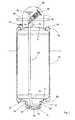
- the container 2 after Fig. 1consists of metal and comprises a cylindrical shell 4, which is welded at the top with a curved bottom 6 and below with a curved bottom 8.
- the lower arched bottom 8has a central, circular opening 10, in which a further cylindrical casing neck 12 is welded, which in turn is completed by a welded arched bottom 14.
- the nozzle 12 and the bottom 14form a bottom cup 16, in which collect the remains of the liquid chemical when emptying the container.
- the bottom cup 16consisting of the casing neck 12 and the bottom 14 is protected against external mechanical damage by a protective cover 18, which consists of a welded to the curved bottom 8 casing nozzle 20 and a curved bottom 22, which is welded to the nozzle piece 20.
- the cylindrical container shell 4is protected against external mechanical damage by an outer jacket 24.
- the outer jacket 24is welded to ring half pipes 26 and 28.
- the ring half pipe 26is welded to the upper arched bottom 6.
- the ring half pipe 28is welded to the lower arched bottom 8. Due to the formation of the ring half pipes 26 and 28, the outer shell 24 sits stress-free on the container. 2
- the ring half tubes 26 and 28further protect the upper and lower domed bottoms 6 and 8 against external mechanical damage.
- a threaded sleeveis welded as a liquid drain 30, to which a hose or pipe can be connected.
- a threaded sleeveis welded as a liquid inlet 32, to which a hose or a pipe can be connected.
- the container 2has eccentrically to its center axis to a discharge line 34 made of metal.
- a pipe section 36is welded obliquely. The pipe section 36 extends almost to the bottom arched bottom 14 of the bottom cup 16th
- a valve 40is welded.
- the valve 40has no gland, but has a liquid-tight bellows.
- a pipe flange 42is welded, thereby forming a first fitting, through which a releasable hydraulic connection of the container 2 can be effected with other apparatus.
- the container 2has a support ring 44, which consists of a circularly curved tube ring whose outer diameter Ring corresponds to the outer diameter of the cylindrical outer shell 24.
- the support ring 44is connected to the upper arched bottom 6 by at least two brackets. In Fig. 1 a holder 46 is visible. Out Fig. 2 two more brackets than 52 and 54 can be seen.
- the container 2has to protect the Flanschstutzen and fittings on an upper guard 48, which is connected to at least two releasable tabs 50 with the upper ring half-tube 26. At the point of removal, the fastening nut 68 is released on each tab connection, whereby the upper protection 48 can be easily removed and the access to the flange 42 is free.
- the tab connection 50consists of a plate angle 62, which is welded onto the ring half-tube 26, and from the eyelet 64, which is welded onto the outer wall of the upper protective cover 48.
- the plate angle 62 and eyelet 64are fixed to each other by the welded on the plate angle 62 threaded connector 66 and by means of the fastening nut 68.
- a second fittingis mounted, whereby the filling of the container is facilitated.
- the fittingconsists of a connecting flange 58, on which the valve 56 is welded.
- the valve 56is glandless and designed as a bellows.
- the valve 56is as out Fig. 4 can be seen hydraulically connected to welded into the upper arched bottom 6 pipe socket 60.
- Fig. 5shows in perspective the arrangement of the valves 40 and 56 and the flanges 42 and 58 on the upper curved bottom 6 of the container. 2
Landscapes
- Engineering & Computer Science (AREA)
- Mechanical Engineering (AREA)
- Ceramic Engineering (AREA)
- Details Of Rigid Or Semi-Rigid Containers (AREA)
- Containers And Packaging Bodies Having A Special Means To Remove Contents (AREA)
Abstract
Translated fromGermanDescription
Translated fromGermanDie Erfindung betrifft einen Behälter für flüssige Chemikalien mit einem zylindrischen Mantel, einem oberen gewölbten Boden und einem unteren gewölbten Boden sowie einem Behälterzufluss und einem Behälterabfluss.The invention relates to a container for liquid chemicals with a cylindrical shell, an upper arched bottom and a lower arched bottom and a container inflow and a container outflow.
Der Erfindung liegt die Aufgabe zugrunde, einen Behälter für flüssige Chemikalien anzugeben, in dem die flüssigen Chemikalien sicher transportiert werden können und der einerseits zum mechanischen Schutz des Behälters und andererseits zur einfachen Handhabung des Behälters dient. Dazu ist der erfindungsgemäße Behälter für flüssige Chemikalien mit einem zylindrischen Behältermantel, einem oberen gewölbten Boden und einem unteren gewölbten Boden sowie einem Behälterzufluss und einem Behälterabfluss, wobei der Behälterzufluss und der Behälterabfluss an dem oberen gewölbten Boden des Behälters angeordnet sind, und wobei ein Entnahmerohr vorgesehen ist, das von dem Behälterabfluss bis zu dem unteren gewölbten Boden reicht, dadurch gekennzeichnet, dass ein Tragering an dem Behälter vorgesehen ist, wobei der Tragering über Halterungen an dem Behälter befestigt ist und den Behälterzufluss und den Behälterabfluss beziehungsweise die obere Schutzhaube mit Abstand umgibt.The invention has for its object to provide a container for liquid chemicals, in which the liquid chemicals can be transported safely and on the one hand serves for the mechanical protection of the container and on the other hand for easy handling of the container. For this, the liquid chemical container of the present invention is provided with a cylindrical container shell, an upper domed bottom and a lower domed bottom, and a container inlet and a container drain, wherein the container inlet and the container drain are located at the upper domed bottom of the container, and wherein a withdrawal tube is provided is, which extends from the container drain to the lower arched bottom, characterized in that a support ring is provided on the container, wherein the support ring is attached to the container via brackets and surrounds the container inlet and the container drain and the upper protective cover at a distance.
Der Tragering dient einerseits zum mechanischen Schutz wiederum der Schutzhaube bzw. der Oberseite des Behälters. Andererseits bietet der Tragering eine einfache Handhabungsmöglichkeit für den Behälter, da der Behälter an dem Tragering erfasst und dann transportiert werden kann. Schließlich kann der Tragering auch dazu dienen, den Behälter an einer Lagerstelle, an einer Wand, einem Pfosten oder dergleichen zu fixieren, indem einfach eine Lasche um den Tragering gelegt wird.The support ring serves on the one hand for mechanical protection turn the guard or the top of the container. On the other hand, the support ring provides a simple handling possibility for the container, since the container can be detected on the support ring and then transported. Finally, the support ring can also serve to fix the container at a bearing point, on a wall, a post or the like by simply placing a tab around the support ring.
Eine vorteilhafte Ausgestaltung des erfindungsgemäßen Behälters ist dadurch gekennzeichnet, dass der Behälterzufluss und der Behälterabfluss als Zufluss-Rohrstutzen beziehungsweise als Abfluss-Rohrstutzen ausgebildet sind. Der erfindungsgemäße Behälter ist damit vorteilhaft so ausgestaltet, dass die Leitungen für die Zufuhr und die Entnahme der flüssigen Chemikalien leicht an den Behälter angeschlossen werden können.An advantageous embodiment of the container according to the invention is characterized in that the container inlet and the container drain are formed as inflow pipe socket or as drain pipe socket. The container according to the invention is thus advantageously designed so that the lines for the supply and removal of the liquid chemicals can be easily connected to the container.
Eine weitere vorteilhafte Ausgestaltung des erfindungsgemäßen Behälters ist dadurch gekennzeichnet, dass an dem Behälterzufluss und dem Behälterabfluss jeweils ein Absperrventil vorgesehen ist. Obwohl auch Ventile die Steuerung des Zuflusses und des Abflusses in der Versorgungseinrichtung für den Behälter vorgesehen sein können, ist es vorteilhaft, wenn dem Behälterzufluss und dem Behälterabfluss Absperrventile vorgesehen sind, weil der Betrieb des Behälters dann unabhängig der von den besten Voraussetzungen der Befüllungsvorrichtung oder der Entnahmevorrichtung möglich ist.A further advantageous embodiment of the container according to the invention is characterized in that a check valve is provided in each case on the container inflow and the container outflow. Although valves, the control of the inflow and outflow can be provided in the supply device for the container, it is advantageous if the container inlet and the container drain shut-off valves are provided because the operation of the container then regardless of the best conditions of the filling device or the Removal device is possible.
Eine weitere vorteilhafte Ausgestaltung des erfindungsgemäßen Behälters ist dadurch gekennzeichnet, dass eine obere Schutzhaube vorgesehen ist, die im montierten Zustand den Behälterzufluss und den Behälterabfluss abdeckt. Diese Schutzhaube dient vorteilhafterweise beim Transport und bei der Lagerung des Behälters zum Schutz der Armaturen, die an der Oberseite des Behälters angeordnet sind. Wenn der Behälter in Betrieb genommen wird und die Armaturen zugänglich sein müssen, kann die Schutzhaube leicht abgenommen werden.A further advantageous embodiment of the container according to the invention is characterized in that an upper protective cover is provided, which covers the container inflow and the container outflow in the assembled state. This guard is advantageously used during transport and storage of the container to protect the fittings, which are arranged at the top of the container. When the container is put into operation and the fittings must be accessible, the protective cover can be easily removed.
Eine weitere vorteilhafte Ausgestaltung des erfindungsgemäßen Behälters ist dadurch gekennzeichnet, dass die obere Schutzhaube über eine lösbare Laschenverbindung mit dem Behälter verbunden ist, wobei dies eine vorteilhafte und besonders einfache Lösung für das Abnehmen der Schutzhaube darstellt.A further advantageous embodiment of the container according to the invention is characterized in that the upper guard is connected via a releasable tab connection with the container, which represents an advantageous and particularly simple solution for removing the guard.
Weitere Vorteile, Merkmale und Anwendungsmöglichkeiten der vorliegenden Erfindung ergeben sich aus der nachfolgenden Beschreibung in Verbindung mit den in den Zeichnungen dargestellten Ausführungsbeispielen.Further advantages, features and possible applications of the present invention will become apparent from the following description in conjunction with the embodiments illustrated in the drawings.
In der Beschreibung, in den Ansprüchen und in der Zeichnung werden die in der unten aufgeführten Liste der Bezugszeichen verwendeten Begriffe und zugeordneten Bezugszeichen verwendet. In der Zeichnung bedeutet:
- Fig. 1
- zeigt einen Vertikalschnitt durch den erfindungsgemäßen Behälter;
- Fig. 2
- zeigt eine Draufsicht auf die Oberseite des Behälters von
Fig. 1 ; - Fig. 3
- zeigt die Laschenverbindung zwischen der Schutzhaube und dem Behälter;
- Fig. 4
- zeigt eine Seitenansicht des erfindungsgemäßen Behälters von
Fig. 1 , und - Fig. 5
- zeigt eine perspektivische Darstellung des Behälters nach den
Figs. 1 bis 4 .
- Fig. 1
- shows a vertical section through the container according to the invention;
- Fig. 2
- shows a plan view of the top of the container of
Fig. 1 ; - Fig. 3
- shows the tab connection between the guard and the container;
- Fig. 4
- shows a side view of the container according to the invention of
Fig. 1 , and - Fig. 5
- shows a perspective view of the container after the
Figs. 1 to 4 ,
Der Behälter 2 nach
Der untere gewölbte Boden 8 besitzt eine zentrische, kreisförmige Öffnung 10, in die ein weiterer zylindrischer Mantelstutzen 12 eingeschweißt ist, welcher seinerseits durch einen angeschweißten gewölbten Boden 14 abgeschlossen ist. Der Mantelstutzen 12 und der Boden 14 bilden einen Bodennapf 16, in dem sich bei Entleerung des Behälters die Reste der flüssigen Chemikalie sammeln. Diese Ausführung ist von besonderem Vorteil, wenn der Behälter 2 bei dem Entleerungsvorgang sich nicht in völlig vertikaler Position befindet.The lower
Der Bodennapf 16 bestehend aus dem Mantelstutzen 12 und dem Boden 14 wird gegen äußere mechanische Beschädigung durch eine Schutzhaube 18 geschützt, welche aus einem an den gewölbten Boden 8 angeschweißten Mantelstutzen 20 und aus einem gewölbten Boden 22 besteht, welcher an den Mantelstutzen 20 angeschweißt ist.The
Der zylindrische Behältermantel 4 wird gegen äußere mechanische Beschädigung durch einen Außenmantel 24 geschützt. Der Außenmantel 24 ist mit Ringhalbrohren 26 und 28 verschweißt. Das Ringhalbrohr 26 ist an den oberen gewölbten Boden 6 angeschweißt. Das Ringhalbrohr 28 ist an den unteren gewölbten Boden 8 angeschweißt. Durch die Ausformung mit den Ringhalbrohren 26 und 28 sitzt der Außenmantel 24 spannungsfrei auf dem Behälter 2.The
Die Ringhalbrohre 26 und 28 schützen weiterhin die oberen und unteren gewölbten Böden 6 und 8 gegen äußere mechanische Beschädigung.The
Auf das Ringhalbrohr 26 ist eine Gewindemuffe als Flüssigkeitsabfluss 30 aufgeschweißt, woran ein Schlauch oder Rohr angeschlossen werden kann. Auf das Ringhalbrohr 28 ist eine Gewindemuffe als Flüssigkeitszufluss 32 aufgeschweißt, woran ein Schlauch oder ein Rohr angeschlossen werden kann.On the ring
Der Behälter 2 weist exzentrisch zu seiner Mittenachse eine Entnahmeleitung 34 aus Metall auf. Unten an die Entnahmeleitung 34 ist ein Rohrstück 36 schräg angeschweißt. Das Rohrstück 36 reicht bis fast auf den Grund gewölbten Bodens 14 des Bodennapfes 16.The
Oben ist die Entnahmeleitung 34 mit dem Rohrstutzen 38 hydraulisch verbunden. Der Rohrstutzen 38 ist in den oberen gewölbten Boden 6 eingeschweißt. An den Rohrstutzen 38 ist ein Ventil 40 angeschweißt. Vorzugsweise weist das Ventil 40 keine Stopfbuchse auf, sondern hat einen flüssigkeitsdichten Faltenbalg. An das Ventil 40 ist ein Rohrflansch 42 angeschweißt, wobei dadurch eine erste Armatur gebildet wird, durch die eine lösbare hydraulische Verbindung des Behälters 2 mit anderen Apparaten bewirkt werden kann.Above the
Der Behälter 2 weist einen Tragering 44 auf, welcher aus einem kreisförmig gebogenen Rohrring besteht, dessen Ringaußendurchmesser dem Außendurchmesser des zylindrischen Außenmantels 24 entspricht. Der Tragering 44 ist mit dem oberen gewölbten Boden 6 durch mindestens zwei Halterungen verbunden. In
Der Behälter 2 weist zum Schutz der Flanschstutzen und Armaturen eine obere Schutzhaube 48 auf, welche mit mindestens zwei lösbaren Laschen 50 mit dem oberen Ringhalbrohr 26 verbunden ist. Am Entnahmeort wird die Befestigungsmutter 68 auf jeder Laschenverbindung gelöst, wodurch die obere Schutzhabe 48 leicht entfernt werden kann und der Zugang zum Flansch 42 frei wird.The
Die Einzelheiten der Laschenverbindung 50 sind
Auf dem oberen gewölbten Boden 6 des Behälters 2 ist eine zweite Armatur angebracht, wodurch das Befüllen des Behälters erleichtert wird. Wie aus
- 22
- Behältercontainer
- 44
- Zylindrischer BehältermantelCylindrical container casing
- 66
- Oberer gewölbter Boden des BehältersUpper arched bottom of the tank
- 88th
- Unterer gewölbter Boden des BehältersBottom arched bottom of the tank
- 1010
- Öffnungopening
- 1212
- Zylindrischer Mantel des BodennapfesCylindrical coat of ground bowl
- 1414
- Gewölbter Boden des BodennapfesArched bottom of the ground bowl
- 1616
- BodennapfBodennapf
- 1818
- Schutzhaubeguard
- 2020
- Mantel der unteren SchutzhaubeSheath of the lower protective cover
- 2222
- Gewölbter Boden der unteren SchutzhaubeArched bottom of the lower guard
- 2424
- Zylindrischer AußenmantelCylindrical outer jacket
- 2626
- Oberes Ringhalbrohr für AußenmantelUpper ring half tube for outer jacket
- 2828
- Unteres Ringhalbrohr für AußenmantelLower ring half pipe for outer jacket
- 3030
- Abflussstutzendrain socket
- 3232
- Zuflussstutzensupply connection
- 3434
- FörderrohrleitungProduction tubing
- 3636
- Rohrstückpipe section
- 3838
- Rohrstutzenpipe socket
- 4040
- VentilValve
- 4242
- Flanschflange
- 4444
- Trageringsupport ring
- 4646
- Halterung für TrageringHolder for carrying ring
- 4848
- Obere SchutzhaubeUpper protective hood
- 5050
- lösbare Laschenverbindungdetachable tab connection
- 5252
- Halterung für TrageringHolder for carrying ring
- 5454
- Halterung für TrageringHolder for carrying ring
- 5656
- VentilValve
- 5858
- Flanschflange
- 6060
- Rohrstutzenpipe socket
- 6262
- BlechwinkelBlechwinkel
- 6464
- Öseeyelet
- 6666
- Gewindestutzenthreaded connector
- 6868
- Schraubmutternut
Claims (7)
Translated fromGermandadurch gekennzeichnet, dass ein Tragering (44) an dem Behälter vorgesehen ist, wobei der Tragering (44) über Halterungen an dem Behälter befestigt ist und den Behälterzufluss (58, 60) und den Behälterabfluss (38, 42) beziehungsweise eine obere Schutzhaube (48) mit Abstand umgibt.Container for liquid chemicals comprising a cylindrical container shell (4), an upper arched bottom (6) and a lower arched bottom (8) and a container inflow (58, 60) and a container outflow (38, 42), wherein the container inflow ( 58, 60) and the container drain (38, 42) on the upper curved bottom (6) of the container are arranged, and wherein a discharge pipe (34) is provided, which from the container drain (38, 42) to the lower arched bottom (8) is enough
characterized in that a support ring (44) is provided on the container, wherein the support ring (44) is attached to the container via supports and the container inflow (58, 60) and the container outflow (38, 42) or an upper protective cover (48 ) surrounds at a distance.
Applications Claiming Priority (2)
| Application Number | Priority Date | Filing Date | Title |
|---|---|---|---|
| DE201120050795DE202011050795U1 (en) | 2011-07-22 | 2011-07-22 | Container for liquid chemicals |
| EP12746046.7AEP2734452B1 (en) | 2011-07-22 | 2012-07-20 | Container for liquid chemicals |
Related Parent Applications (2)
| Application Number | Title | Priority Date | Filing Date |
|---|---|---|---|
| EP12746046.7ADivisionEP2734452B1 (en) | 2011-07-22 | 2012-07-20 | Container for liquid chemicals |
| EP12746046.7ADivision-IntoEP2734452B1 (en) | 2011-07-22 | 2012-07-20 | Container for liquid chemicals |
Publications (1)
| Publication Number | Publication Date |
|---|---|
| EP2865605A1true EP2865605A1 (en) | 2015-04-29 |
Family
ID=44786756
Family Applications (2)
| Application Number | Title | Priority Date | Filing Date |
|---|---|---|---|
| EP20140196243WithdrawnEP2865605A1 (en) | 2011-07-22 | 2012-07-20 | Liquid chemical container |
| EP12746046.7ANot-in-forceEP2734452B1 (en) | 2011-07-22 | 2012-07-20 | Container for liquid chemicals |
Family Applications After (1)
| Application Number | Title | Priority Date | Filing Date |
|---|---|---|---|
| EP12746046.7ANot-in-forceEP2734452B1 (en) | 2011-07-22 | 2012-07-20 | Container for liquid chemicals |
Country Status (6)
| Country | Link |
|---|---|
| US (2) | US20140191000A1 (en) |
| EP (2) | EP2865605A1 (en) |
| CN (2) | CN104495004A (en) |
| BR (1) | BR112014001188A2 (en) |
| DE (1) | DE202011050795U1 (en) |
| WO (1) | WO2013014095A1 (en) |
Families Citing this family (3)
| Publication number | Priority date | Publication date | Assignee | Title |
|---|---|---|---|---|
| DE102012204902A1 (en)* | 2012-03-27 | 2013-10-02 | Evonik Degussa Gmbh | Containers for handling and transporting high purity and ultra high purity chemicals |
| CN109094925A (en)* | 2017-06-20 | 2018-12-28 | 瀚宇彩晶股份有限公司 | Liquid containing barrel |
| CN111571125B (en)* | 2020-05-06 | 2022-02-15 | 九江市永信制罐设备有限公司 | Small square tank production process |
Citations (5)
| Publication number | Priority date | Publication date | Assignee | Title |
|---|---|---|---|---|
| GB500608A (en)* | 1937-03-27 | 1939-02-13 | Firestone Tire & Rubber Co | Improvements in or relating to liquid containers such as kegs or barrels |
| DE7921351U1 (en)* | 1978-09-01 | 1979-10-31 | Ver Edelstahlwerke Ag | Container |
| GB2196682A (en)* | 1986-10-30 | 1988-05-05 | Merck Patent Gmbh | Transport container with immersion tube reaching to container bottom |
| DE102005024210B3 (en)* | 2005-05-23 | 2007-02-08 | Dockweiler Ag | Metal organic substance accommodating safety tank, has valve block fixed with lid by fixing screws which are inserted through holes of respective connecting plates and running bore holes of block |
| DE102007050573A1 (en)* | 2007-10-23 | 2009-04-30 | Evonik Degussa Gmbh | Large containers for handling and transporting high purity and ultrapure chemicals |
Family Cites Families (21)
| Publication number | Priority date | Publication date | Assignee | Title |
|---|---|---|---|---|
| US2151856A (en)* | 1936-10-26 | 1939-03-28 | Edward F Lee | Cooling system for metal barrels |
| US2116795A (en)* | 1937-02-10 | 1938-05-10 | Edward F Lee | Double walled barrel |
| US2249051A (en)* | 1937-11-08 | 1941-07-15 | Herman E Schulse | Beverage container |
| US3883046A (en)* | 1974-02-11 | 1975-05-13 | Textron Inc | Elastomeric bladder for positive expulsion tank |
| US4103806A (en)* | 1977-01-03 | 1978-08-01 | White E Vernon | Valve guard for protecting the regulator valve on a scuba tank |
| EP0338573B1 (en) | 1988-04-21 | 1992-06-17 | Büdenbender, Bernd | Security container for dangerous and/or precious chemical products |
| US5165569A (en)* | 1990-07-30 | 1992-11-24 | Sapporo Breweries Ltd. | Keg for draft beer |
| CN2110619U (en)* | 1992-01-04 | 1992-07-22 | 山东羊口盐场 | Small-opening barrel-shaped bromine transportation and packaging container |
| AUPQ105099A0 (en)* | 1999-06-18 | 1999-07-08 | Carlton And United Breweries Limited | Beer container |
| CN2407222Y (en)* | 1999-10-18 | 2000-11-22 | 邵惠京 | Special steel bottle for LPG residue |
| JP2001324098A (en)* | 2000-05-15 | 2001-11-22 | Furoomu:Kk | Pressure vessel contents discharge device |
| CN2533373Y (en)* | 2002-02-26 | 2003-01-29 | 刘俊昌 | Liquefied gas enamel cylinder |
| GB0209912D0 (en)* | 2002-05-01 | 2002-06-05 | Cypherco Ltd | Dispenser |
| JP2004019884A (en)* | 2002-06-19 | 2004-01-22 | Mitsubishi Electric Building Techno Service Co Ltd | Refrigerant cylinder |
| EP1507125A3 (en)* | 2003-08-13 | 2008-02-27 | Cool-System Bev. GmbH | Container with at least one vacuum chamber comprising an inlet opening, in particular a container like a beer keg or likewise |
| CN1821028A (en)* | 2006-02-11 | 2006-08-23 | 无锡市恒灵防腐设备有限公司 | Pressure anti-corrosion storage tank with plastic lining |
| CN200965152Y (en)* | 2007-03-15 | 2007-10-24 | 王有正 | Liquefied petroleum gas tank |
| CN201053570Y (en)* | 2007-06-05 | 2008-04-30 | 贾秀军 | Civil fuel alcohol ether storage steel bottle |
| US20110163128A1 (en)* | 2007-08-09 | 2011-07-07 | Asahi Breweries, Ltd. | Beverage container and cooling system for the same |
| CN201358053Y (en)* | 2009-01-06 | 2009-12-09 | 烟台方大滚塑有限公司 | Steel plastic composite tank |
| CN201597817U (en)* | 2010-01-21 | 2010-10-06 | 浙江海洋学院 | a storage tank |
- 2011
- 2011-07-22DEDE201120050795patent/DE202011050795U1/ennot_activeExpired - Lifetime
- 2012
- 2012-07-20USUS14/234,383patent/US20140191000A1/ennot_activeAbandoned
- 2012-07-20CNCN201410648553.8Apatent/CN104495004A/enactivePending
- 2012-07-20EPEP20140196243patent/EP2865605A1/ennot_activeWithdrawn
- 2012-07-20EPEP12746046.7Apatent/EP2734452B1/ennot_activeNot-in-force
- 2012-07-20CNCN201280036429.5Apatent/CN103702907B/ennot_activeExpired - Fee Related
- 2012-07-20WOPCT/EP2012/064327patent/WO2013014095A1/enactiveApplication Filing
- 2012-07-20BRBR112014001188Apatent/BR112014001188A2/ennot_activeApplication Discontinuation
- 2014
- 2014-12-17USUS14/572,777patent/US20150102072A1/ennot_activeAbandoned
Patent Citations (5)
| Publication number | Priority date | Publication date | Assignee | Title |
|---|---|---|---|---|
| GB500608A (en)* | 1937-03-27 | 1939-02-13 | Firestone Tire & Rubber Co | Improvements in or relating to liquid containers such as kegs or barrels |
| DE7921351U1 (en)* | 1978-09-01 | 1979-10-31 | Ver Edelstahlwerke Ag | Container |
| GB2196682A (en)* | 1986-10-30 | 1988-05-05 | Merck Patent Gmbh | Transport container with immersion tube reaching to container bottom |
| DE102005024210B3 (en)* | 2005-05-23 | 2007-02-08 | Dockweiler Ag | Metal organic substance accommodating safety tank, has valve block fixed with lid by fixing screws which are inserted through holes of respective connecting plates and running bore holes of block |
| DE102007050573A1 (en)* | 2007-10-23 | 2009-04-30 | Evonik Degussa Gmbh | Large containers for handling and transporting high purity and ultrapure chemicals |
Also Published As
| Publication number | Publication date |
|---|---|
| US20140191000A1 (en) | 2014-07-10 |
| WO2013014095A1 (en) | 2013-01-31 |
| CN103702907B (en) | 2015-03-25 |
| BR112014001188A2 (en) | 2017-02-21 |
| EP2734452A1 (en) | 2014-05-28 |
| CN103702907A (en) | 2014-04-02 |
| CN104495004A (en) | 2015-04-08 |
| EP2734452B1 (en) | 2016-01-20 |
| US20150102072A1 (en) | 2015-04-16 |
| DE202011050795U1 (en) | 2011-09-12 |
Similar Documents
| Publication | Publication Date | Title |
|---|---|---|
| EP2777794B1 (en) | Filter cartridge and filter device | |
| DE102008028051A1 (en) | Portable device for treating water, in particular water softening device | |
| DE3021378A1 (en) | METAL CONTAINER | |
| EP2865605A1 (en) | Liquid chemical container | |
| DE202011050903U1 (en) | Mixing and dosing device for mixing and dosing of chemicals | |
| US8852355B1 (en) | Elevated potable water tank and tower cleaning system | |
| AT511953A4 (en) | COVER AT THE OUTSIDE OF AN OPERATING TANK | |
| CN103191659A (en) | Dispensing tank | |
| DE102012110812A1 (en) | Biogas reactor with an overpressure vacuum safety device | |
| EP2581326A1 (en) | Film bag inner liner for steel tank | |
| DE3426409C2 (en) | Submersible motor pump unit | |
| EP2965796A1 (en) | Filter | |
| CN217905610U (en) | Plant root drip irrigation equipment for garden maintenance | |
| WO2019137885A1 (en) | Device for draining away waste water | |
| DE102014018168A1 (en) | Pipe flow power plant | |
| DE437032C (en) | Slurry pump | |
| DE69905607T2 (en) | WASTEWATER PUMP WITH PNEUMATICALLY OPERATED SQUEEGEE VALVE | |
| DE102008010360A1 (en) | pump means | |
| EP3305388A1 (en) | Water evaporator and technical system | |
| DE102010032039A1 (en) | Method for closing broken or cracked pipeline, involves separating broken or cracked pipe section by flange of pipeline that is lying sealed below breakage | |
| DE718710C (en) | Heating flange used to close the bottom opening of hot water storage tanks | |
| EP3159315B1 (en) | Device and method for gas injection in a sludge tank for sludge circulation | |
| DE102016120170A1 (en) | Steam generating plant | |
| EP2921710A1 (en) | Continuous flow machine with sealing device, maintenance procedure and associated maintenance devices | |
| DE202015103194U1 (en) | Cleaning device for a shaft insert |
Legal Events
| Date | Code | Title | Description |
|---|---|---|---|
| PUAI | Public reference made under article 153(3) epc to a published international application that has entered the european phase | Free format text:ORIGINAL CODE: 0009012 | |
| 17P | Request for examination filed | Effective date:20141204 | |
| AC | Divisional application: reference to earlier application | Ref document number:2734452 Country of ref document:EP Kind code of ref document:P | |
| AK | Designated contracting states | Kind code of ref document:A1 Designated state(s):AL AT BE BG CH CY CZ DE DK EE ES FI FR GB GR HR HU IE IS IT LI LT LU LV MC MK MT NL NO PL PT RO RS SE SI SK SM TR | |
| STAA | Information on the status of an ep patent application or granted ep patent | Free format text:STATUS: THE APPLICATION HAS BEEN WITHDRAWN | |
| 18W | Application withdrawn | Effective date:20150519 |