EP2862536B1 - Real-time estimation of tissue perforation risk during minimally invasive medical procedure - Google Patents
Real-time estimation of tissue perforation risk during minimally invasive medical procedureDownload PDFInfo
- Publication number
- EP2862536B1 EP2862536B1EP14189511.0AEP14189511AEP2862536B1EP 2862536 B1EP2862536 B1EP 2862536B1EP 14189511 AEP14189511 AEP 14189511AEP 2862536 B1EP2862536 B1EP 2862536B1
- Authority
- EP
- European Patent Office
- Prior art keywords
- tissue
- force
- processor
- perforation
- displacement
- Prior art date
- Legal status (The legal status is an assumption and is not a legal conclusion. Google has not performed a legal analysis and makes no representation as to the accuracy of the status listed.)
- Active
Links
Images


Classifications
- A—HUMAN NECESSITIES
- A61—MEDICAL OR VETERINARY SCIENCE; HYGIENE
- A61B—DIAGNOSIS; SURGERY; IDENTIFICATION
- A61B5/00—Measuring for diagnostic purposes; Identification of persons
- A61B5/0048—Detecting, measuring or recording by applying mechanical forces or stimuli
- A61B5/0053—Detecting, measuring or recording by applying mechanical forces or stimuli by applying pressure, e.g. compression, indentation, palpation, grasping, gauging
- A—HUMAN NECESSITIES
- A61—MEDICAL OR VETERINARY SCIENCE; HYGIENE
- A61B—DIAGNOSIS; SURGERY; IDENTIFICATION
- A61B34/00—Computer-aided surgery; Manipulators or robots specially adapted for use in surgery
- A61B34/10—Computer-aided planning, simulation or modelling of surgical operations
- A—HUMAN NECESSITIES
- A61—MEDICAL OR VETERINARY SCIENCE; HYGIENE
- A61B—DIAGNOSIS; SURGERY; IDENTIFICATION
- A61B18/00—Surgical instruments, devices or methods for transferring non-mechanical forms of energy to or from the body
- A61B18/04—Surgical instruments, devices or methods for transferring non-mechanical forms of energy to or from the body by heating
- A61B18/12—Surgical instruments, devices or methods for transferring non-mechanical forms of energy to or from the body by heating by passing a current through the tissue to be heated, e.g. high-frequency current
- A61B18/14—Probes or electrodes therefor
- A61B18/1492—Probes or electrodes therefor having a flexible, catheter-like structure, e.g. for heart ablation
- A—HUMAN NECESSITIES
- A61—MEDICAL OR VETERINARY SCIENCE; HYGIENE
- A61B—DIAGNOSIS; SURGERY; IDENTIFICATION
- A61B5/00—Measuring for diagnostic purposes; Identification of persons
- A61B5/68—Arrangements of detecting, measuring or recording means, e.g. sensors, in relation to patient
- A61B5/6846—Arrangements of detecting, measuring or recording means, e.g. sensors, in relation to patient specially adapted to be brought in contact with an internal body part, i.e. invasive
- A61B5/6867—Arrangements of detecting, measuring or recording means, e.g. sensors, in relation to patient specially adapted to be brought in contact with an internal body part, i.e. invasive specially adapted to be attached or implanted in a specific body part
- A61B5/6869—Heart
- A—HUMAN NECESSITIES
- A61—MEDICAL OR VETERINARY SCIENCE; HYGIENE
- A61B—DIAGNOSIS; SURGERY; IDENTIFICATION
- A61B5/00—Measuring for diagnostic purposes; Identification of persons
- A61B5/68—Arrangements of detecting, measuring or recording means, e.g. sensors, in relation to patient
- A61B5/6846—Arrangements of detecting, measuring or recording means, e.g. sensors, in relation to patient specially adapted to be brought in contact with an internal body part, i.e. invasive
- A61B5/6885—Monitoring or controlling sensor contact pressure
- A—HUMAN NECESSITIES
- A61—MEDICAL OR VETERINARY SCIENCE; HYGIENE
- A61B—DIAGNOSIS; SURGERY; IDENTIFICATION
- A61B90/00—Instruments, implements or accessories specially adapted for surgery or diagnosis and not covered by any of the groups A61B1/00 - A61B50/00, e.g. for luxation treatment or for protecting wound edges
- A61B90/03—Automatic limiting or abutting means, e.g. for safety
- A—HUMAN NECESSITIES
- A61—MEDICAL OR VETERINARY SCIENCE; HYGIENE
- A61B—DIAGNOSIS; SURGERY; IDENTIFICATION
- A61B17/00—Surgical instruments, devices or methods
- A61B2017/00017—Electrical control of surgical instruments
- A61B2017/00022—Sensing or detecting at the treatment site
- A—HUMAN NECESSITIES
- A61—MEDICAL OR VETERINARY SCIENCE; HYGIENE
- A61B—DIAGNOSIS; SURGERY; IDENTIFICATION
- A61B17/00—Surgical instruments, devices or methods
- A61B2017/00017—Electrical control of surgical instruments
- A61B2017/00022—Sensing or detecting at the treatment site
- A61B2017/00075—Motion
- A—HUMAN NECESSITIES
- A61—MEDICAL OR VETERINARY SCIENCE; HYGIENE
- A61B—DIAGNOSIS; SURGERY; IDENTIFICATION
- A61B17/00—Surgical instruments, devices or methods
- A61B2017/00017—Electrical control of surgical instruments
- A61B2017/00115—Electrical control of surgical instruments with audible or visual output
- A61B2017/00119—Electrical control of surgical instruments with audible or visual output alarm; indicating an abnormal situation
- A—HUMAN NECESSITIES
- A61—MEDICAL OR VETERINARY SCIENCE; HYGIENE
- A61B—DIAGNOSIS; SURGERY; IDENTIFICATION
- A61B17/00—Surgical instruments, devices or methods
- A61B2017/00017—Electrical control of surgical instruments
- A61B2017/00115—Electrical control of surgical instruments with audible or visual output
- A61B2017/00128—Electrical control of surgical instruments with audible or visual output related to intensity or progress of surgical action
- A—HUMAN NECESSITIES
- A61—MEDICAL OR VETERINARY SCIENCE; HYGIENE
- A61B—DIAGNOSIS; SURGERY; IDENTIFICATION
- A61B18/00—Surgical instruments, devices or methods for transferring non-mechanical forms of energy to or from the body
- A61B2018/00005—Cooling or heating of the probe or tissue immediately surrounding the probe
- A—HUMAN NECESSITIES
- A61—MEDICAL OR VETERINARY SCIENCE; HYGIENE
- A61B—DIAGNOSIS; SURGERY; IDENTIFICATION
- A61B18/00—Surgical instruments, devices or methods for transferring non-mechanical forms of energy to or from the body
- A61B2018/00315—Surgical instruments, devices or methods for transferring non-mechanical forms of energy to or from the body for treatment of particular body parts
- A61B2018/00345—Vascular system
- A61B2018/00351—Heart
- A—HUMAN NECESSITIES
- A61—MEDICAL OR VETERINARY SCIENCE; HYGIENE
- A61B—DIAGNOSIS; SURGERY; IDENTIFICATION
- A61B18/00—Surgical instruments, devices or methods for transferring non-mechanical forms of energy to or from the body
- A61B2018/00571—Surgical instruments, devices or methods for transferring non-mechanical forms of energy to or from the body for achieving a particular surgical effect
- A61B2018/00577—Ablation
- A—HUMAN NECESSITIES
- A61—MEDICAL OR VETERINARY SCIENCE; HYGIENE
- A61B—DIAGNOSIS; SURGERY; IDENTIFICATION
- A61B18/00—Surgical instruments, devices or methods for transferring non-mechanical forms of energy to or from the body
- A61B2018/00571—Surgical instruments, devices or methods for transferring non-mechanical forms of energy to or from the body for achieving a particular surgical effect
- A61B2018/00595—Cauterization
- A—HUMAN NECESSITIES
- A61—MEDICAL OR VETERINARY SCIENCE; HYGIENE
- A61B—DIAGNOSIS; SURGERY; IDENTIFICATION
- A61B18/00—Surgical instruments, devices or methods for transferring non-mechanical forms of energy to or from the body
- A61B2018/00636—Sensing and controlling the application of energy
- A61B2018/00898—Alarms or notifications created in response to an abnormal condition
- A—HUMAN NECESSITIES
- A61—MEDICAL OR VETERINARY SCIENCE; HYGIENE
- A61B—DIAGNOSIS; SURGERY; IDENTIFICATION
- A61B90/00—Instruments, implements or accessories specially adapted for surgery or diagnosis and not covered by any of the groups A61B1/00 - A61B50/00, e.g. for luxation treatment or for protecting wound edges
- A61B90/06—Measuring instruments not otherwise provided for
- A61B2090/064—Measuring instruments not otherwise provided for for measuring force, pressure or mechanical tension
- A61B2090/065—Measuring instruments not otherwise provided for for measuring force, pressure or mechanical tension for measuring contact or contact pressure
- A—HUMAN NECESSITIES
- A61—MEDICAL OR VETERINARY SCIENCE; HYGIENE
- A61B—DIAGNOSIS; SURGERY; IDENTIFICATION
- A61B2562/00—Details of sensors; Constructional details of sensor housings or probes; Accessories for sensors
- A61B2562/02—Details of sensors specially adapted for in-vivo measurements
- A—HUMAN NECESSITIES
- A61—MEDICAL OR VETERINARY SCIENCE; HYGIENE
- A61B—DIAGNOSIS; SURGERY; IDENTIFICATION
- A61B2562/00—Details of sensors; Constructional details of sensor housings or probes; Accessories for sensors
- A61B2562/02—Details of sensors specially adapted for in-vivo measurements
- A61B2562/0223—Magnetic field sensors
- A—HUMAN NECESSITIES
- A61—MEDICAL OR VETERINARY SCIENCE; HYGIENE
- A61B—DIAGNOSIS; SURGERY; IDENTIFICATION
- A61B5/00—Measuring for diagnostic purposes; Identification of persons
- A61B5/72—Signal processing specially adapted for physiological signals or for diagnostic purposes
- A61B5/7235—Details of waveform analysis
- A61B5/7239—Details of waveform analysis using differentiation including higher order derivatives
Definitions
- the present inventionrelates generally to invasive medical procedures, and particularly to systems for estimating the risk of tissue perforation during application of medical procedures.
- Minimally-invasive intracardiac ablationis the treatment of choice for various types of arrhythmias.
- the physiciantypically inserts a catheter through the vascular system into the heart, brings the distal end of the catheter into contact with myocardial tissue in areas of abnormal electrical activity, and then energizes one or more electrodes at or near the distal end in order to create tissue necrosis.
- CARTOintracardiac ablation therapy
- Biosense Webster Inc.Diamond Bar, California
- CARTOtracks the position and operating parameters of the distal end of the catheter and displays this information electronically on a three-dimensional (3D) anatomical map of the heart.
- CARTOenables the system operator to electronically tag locations that have been ablated on the map and thus to keep track of the progress of the procedure.
- the physiciantypically forces the catheter towards the heart inner surface tissue (myocardium). If during the medical procedure (e.g., ablation) the catheter exerts a force upon the tissue that is higher than the force the tissue can tolerate, the catheter may eventually perforate the tissue. As a result, blood or other fluids filling the heart chamber may flow through the perforated tissue to fill up the space between the heart and the pericardium (i.e., the pericardial cavity), a situation referred to as cardiac tamponade.
- the pericardiumi.e., the pericardial cavity
- U.S. Patent 6,351,667describes an apparatus for detecting pericardial effusion that includes a measurement apparatus connected to a wire probe to be anchored on the right heart ventricle and to two other wire probes to be anchored in different regions of the pericardial sac.
- the measurement apparatusmeasures and displays the change in impedance between the individual wire probes.
- European Patent Application Publication EP 2248480describes various embodiments that predict the volume, area and/or depth of lesions created through the use of a force-time integration technique. Other embodiments control the energy delivered to the ablation probe based on the contact force between the ablation probe and the target tissue to prevent steam popping. In another aspect, various embodiments of the invention reliably visualize the predicted volume, area and/or depth of lesions created during ablation procedures. One embodiment visualizes the predicted lesions created utilizing a force contact density mapping procedure. Another embodiment visualizes the predicted lesions through the use of a force-time integration technique. Yet another embodiment visualizes the predicted lesions through the use of a force time and power (and/or current) integration technique. Other embodiments predict the occurrence and locations tissue damage such as perforation that occurred during the ablation process. Still other embodiments predict the occurrence and location of isolation gaps that may occur during or after the procedure.
- European Patent EP 1229829describes a system for detecting the presence of a perforation in a body cavity.
- the systemincludes a fluid pressure source; a medical device insertable into a body cavity, the medical device fluidly coupled to the fluid pressure source for delivery of fluid to the body cavity; and a pressure sensor positioned to detect a pressure of the fluid delivered to the body cavity.
- European patent application EP 2529667 A2describes apparatus for detection of tenting at a surgical site comprising a processor which is configured to detect tenting of the tissue responsively to a relation between measured force and measured displacement.
- the inventionis defined in the independent claims. Preferred embodiments are disclosed in the dependent claims.
- the disclosurealso provides an exemplary method, not according to the invention, for performing a medical procedure, including coupling a tip of a probe to tissue in an organ of a patient in order to apply the medical procedure using the probe. A force exerted by the tip on the tissue and a displacement of the tip created by the force are measured. A dependence of the force on the displacement is calculated. Based on the calculated dependence, a risk level of perforation of the tissue is estimated.
- calculating the dependenceincludes calculating a gradient of the force as a function of the displacement, and estimating the risk level includes comparing the gradient to a predefined gradient threshold. In other embodiments, estimating the risk level includes predicting that the perforation is not imminent upon detecting that the gradient is lower than the predefined gradient threshold. In yet other embodiments, estimating the risk level includes predicting that the perforation is imminent upon detecting that the gradient is higher than the predefined gradient threshold.
- estimating the risk levelincludes identifying that the perforation has occurred upon detecting that the force is inversely-related to the displacement.
- measuring the displacementincludes measuring a first position when the tip is initially coupled to the tissue, measuring a second position when the tip exerts the force on the tissue, and calculating the displacement as the difference between the second and the first positions.
- the methodfurther includes indicating the estimated risk level to an operator of the medical procedure.
- indicating the risk levelincludes indicating an audible or visual alert. In other embodiments, indicating the risk level includes outputting a first indication if the risk level indicates an imminent perforation, and outputting a second indication, different from the first indication, if the risk level indicates an actual perforation.
- an apparatus for performing a medical procedureincludes an invasive probe and a processor.
- the invasive probecomprises a probe tip, which is configured to be coupled to tissue in an organ of a patient.
- the processoris coupled to the probe and is configured to measure a force exerted by the tip on the tissue and a displacement of the tip created by the force, to calculate a dependence of the force on the displacement, and to estimate, based on the calculated dependence, a risk level of perforation of the tissue.
- a computer software productincluding a non-transitory computer-readable medium in which program instructions are stored, which instructions, when read by a processor that is coupled to a tip of an invasive probe for applying a medical procedure to tissue in an organ to which the tip is coupled, cause the processor to measure a force exerted by the tip on the tissue and a displacement of the tip created by the force, to calculate a dependence of the force on the displacement, and to estimate, based on the calculated dependence, a risk level of perforation of the tissue.
- the physicianIn minimally invasive procedures, the physician typically inserts a catheter through the vascular system into a body organ, and brings the distal end of the catheter into contact with the internal tissue surface of the organ. In some cases, such as cardiac ablation, the medical procedure requires that the catheter would exert a certain level of force or pressure on the tissue.
- tentingWhen the force exerted by the catheter is relatively small, tissue neighboring the catheter contact point is pushed away, forming a tent-like shape. This effect is referred to as tenting. In tenting, the tissue maintains flexibility and can safely tolerate the catheter force. At higher force levels, there is risk of tissue perforation that should be avoided.
- Tissue perforationis of particular significance in medical procedures that cause the tissue under treatment to weaken. For example, during cardiac ablation, energy is applied to the tissue to create local necrosis. As a result, the structure or texture of the ablated tissue may change and/or the tissue may become thinner or weaker, and therefore the ablated tissue may not be able to tolerate the catheter force. In such medical procedures, there is a high risk of tissue perforation and accompanying complications.
- the cathetercomprises sensors for performing real-time measurements of the catheter position (or displacement relative to some initial position) and of the force the catheter exerts upon the tissue. Force and displacement measurements are delivered to a processor that calculates from successive measurements differential changes (e.g., ⁇ F and ⁇ D) to derive instantaneous gradient values ⁇ F/ ⁇ D.
- a processorthat calculates from successive measurements differential changes (e.g., ⁇ F and ⁇ D) to derive instantaneous gradient values ⁇ F/ ⁇ D.
- the magnitude and sign of the gradientare used for estimating the risk of tissue perforation.
- Experimentationhas shown that as the catheter is pushed deeper into the tissue, the resistance of the tissue increases, and as a result a higher increase in the exerted force is required to achieve a constant increase in the displacement.
- the force-displacement gradientincreases at higher force and displacement levels. Entry into a risk zone, in which perforation is imminent, corresponds to a force-displacement dependence that indicates a gradient that is higher than a predefined threshold. If the dependence changes sign, i.e., the force begins to decrease as a function of the displacement, perforation is likely to have occurred.
- the risk of imminent perforationis estimated to be low. If the processor detects positive gradient values above the risk threshold, the risk of perforation is estimated to be high. Moreover, a situation in which gradient values become negative is indicative of a high risk that actual perforation has occurred.
- the force and displacement measurementsmay be used, in addition to or instead of the force-displacement gradient, for estimating the risk of tissue perforation.
- the processorproduces suitable alerts to the physician. Alerted by such real-time risk indications, the physician can take suitable measures, in advance, to predict and prevent tissue perforation.
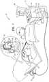
- Fig. 1is a schematic illustration of a system 20 for estimating the risk of tissue perforation during application of a minimally invasive procedure, in accordance with an embodiment of the present invention.
- System 20comprises a probe 22, herein assumed to be a catheter, and a control console 24.
- probe 22may be used for ablation of tissue in a heart 26 of a patient 28 in order to treat cardiac arrhythmias.
- probe 22may be used for other therapeutic and/or diagnostic purposes, such as for mapping electrical potentials in the heart or in another body organ.
- Console 24comprises a processor 42, typically a general-purpose computer, with suitable front end and interface circuits for receiving signals from probe 22 and for controlling the other components of system 20 described herein.
- Processor 42may be programmed in software to carry out the functions that are used by the system, and the processor stores data for the software in a memory 50.
- the softwaremay be downloaded to console 24 in electronic form, over a network, for example, or it may be provided on non-transitory tangible media, such as optical, magnetic or electronic memory media.
- some or all of the functions of processor 42may be carried out by dedicated or programmable digital hardware components.
- System 20typically uses magnetic position sensing to determine position coordinates of the distal end inside heart 26.
- console 24comprises a driver circuit 34, which drives magnetic field generators 36 placed at known positions external to patient 28, e.g., below the patient's torso.
- a magnetic field sensor 38within the distal end of the probe generates electrical position signals in response to the magnetic fields from the coils, thereby enabling processor 42 to determine the position, i.e., the location and typically also the orientation, of distal end 32 within the chamber.
- the magnetic field sensor(i.e., the position sensor) typically comprises one or more coils, usually three coils orthogonal to each other.
- This method of position sensingis implemented, for example, in the CARTOTM system, produced by Biosense Webster Inc. (Diamond Bar, Calif.) and is described in detail in U.S. Pat. Nos. 5,391,199 , 6,690,963 , 6,484,118 , 6,239,724 , 6,618,612 and 6,332,089 , in PCT Patent Publication WO 96/05768 , and in U.S. Patent Application Publications 2002/0065455 A1 , 2003/0120150 A1 and 2004/0068178 A1 .
- driver circuit 34may drive a magnetic field generator in distal end 32 to generate one or more magnetic fields.
- the coils in generator 36may be configured to sense the fields and generate signals indicative of the amplitudes of the components of these magnetic fields.
- Processor 42receives and processes these signals in order to determine the position of distal end 32 within heart 26.
- position tracking techniquesfor example, tracking systems based on impedance measurements. Impedance-based position tracking techniques are described, for example, in U.S. Patents 5,983,126 , 6,456,864 and 5,944,022 . Other position tracking techniques, known to one having ordinary skill in the art, may be used to determine the position of the distal end 32.
- position or displacement sensoris used to refer to any element which provides signals, according to the location and orientation of a probe or a section of a probe, such as the probe's distal end, to console 24.
- the distal end of probe 22also comprises a force sensor 48 (also in Fig. 2 below) which is able to provide electrical force signals to processor 42 in order to measure the magnitude and direction of the force on the distal end (or equivalently the force the catheter applies upon the tissue).
- the direction of the forceis typically measured relative to the symmetry axis of the distal end.
- Various techniquesmay be used in measuring the force. Components and methods that may be used for this purpose are described, for example, in U.S. Patent Application Publications 2009/0093806 and 2009/0138007 .
- operator 30manipulates probe 22 so that distal end 32 is at multiple locations on (or in close proximity to) the inner surface of the chamber.
- an electrode 40coupled to the distal end measures a certain physiological property (e.g., the local surface electrical potential).
- Processor 42correlates the location measurements, derived from the position signals of sensor 38, and the electrical potential measurements.
- the systemcollects multiple map points, with each map point comprising a coordinate on the inner chamber surface and a respective physiological property measurement at this coordinate.
- Processor 42uses the coordinates of the map points to construct a simulated surface of the cardiac chamber in question. Processor 42 then combines the electrical potential measurements of the map points with the simulated surface to produce a map of the potentials overlaid on the simulated surface. Processor 42 displays an image 44 of the map to operator 30 on a display 46.
- processor 42uses at least the force and displacement measurements performed by sensors 38 and 48 to assess the risk of tissue perforation.
- Processor 42presents audiovisual indications and alerts regarding the estimated risk on display 46, to enable operator 30 to take suitable measures, in advance, to prevent tissue perforation.
- Fig. 2is a schematic illustration of a probe causing tissue tenting, in accordance with an embodiment of the present invention.
- the figuredepicts distal end 32 of a probe that is in contact with tissue surface 100.
- tissue surface 100may represent the inner surface of a chamber wall in heart 26.
- the probecomprises position sensor 38 and force sensor 48 as described above with reference to Fig. 1 .
- operator 30In order to apply ablation, operator 30 typically forces the probe towards the tissue.
- the probemay be positioned perpendicularly to the tissue, or obliquely as depicted in the figure.
- a perpendicular force component F 120the tissue is pushed in the force direction into a tenting position depicted in Fig. 2 in dashed lines.
- the position of the probe when it first comes into contact with the tissueis marked by a line 108 and in the tenting position by a line 124.
- position 108serves as an initial or calibrated position for displacement measurements.
- the displacement between initial position 108 and position 124is denoted D 128.
- Displacement D 128is aligned with the direction of force F 120.
- Force sensor 48 and position sensor 38are configured to measure F and D, respectively.
- processor 42may use raw (i.e., non-calibrated) position and force magnitude/direction measurements to calculate D and F.
- U.S. Patent Application Publication 2012/0310116describes a method that includes measuring a force exerted by a probe on tissue of a patient and measuring a displacement of the probe while measuring the force. The method further includes detecting a tenting of the tissue responsively to a relation between the measured force and the measured displacement.
- U.S. Patent Application 13/680,496, filed November 19, 2012 , published as US2014142438 A1describes a method that includes pressing a distal end of a medical probe against a wall of a body cavity, and receiving from the probe first measurements of a force exerted by the distal end on the wall. The method also includes receiving from the probe second measurements indicating a displacement of the wall in response to the force. The method further includes estimating a thickness of the wall based on the first and the second measurements.
- Fig. 3is a graph 150 showing a relationship between force and displacement of an invasive probe, in accordance with an embodiment of the present invention.
- Graph 150was created using a software simulation based on physical analysis and field experience of the inventors.
- the vertical force axis F and the horizontal displacement axis Dmay represent, for example, F 120 and D 128 of Fig. 2 .
- Relationship 150is depicted as a curve that is divided into three zones. In the range 0-D2, also referred to as a tenting zone 154, the flexibility of the tissue is maintained and the relationship between the force exerted upon the tissue and the respective displacement indicates a positive force-displacement gradient.
- F and Dexhibit an increasing gradient behavior wherein the ratio between respective small changes in the force and displacement (i.e., the gradient or slope) ⁇ F1/ ⁇ D1 at low force and displacement levels is smaller than the ratio ⁇ F2/ ⁇ D2, which is measured at higher force and displacement levels.
- a perforation-risk zone 158which resides at the upper end of tenting zone 154, the gradient of curve 150 at points of displacements in the range D1-D2 created by forces in the range F1-F2 is positive.
- the gradient ⁇ F2/ ⁇ D2is significantly higher than in the 0-D1 zone.
- the behavior in zone 158demonstrates that the tissue resistance significantly increases due to forces higher than F1, and therefore a larger force increase is required at the perforation-risk zone than in the 0-D1 zone in order to create similar displacement increases.
- Perforation zone 162relates to forces lower than F2 and displacements higher than D2 respectively. At the perforation zone the probe actually punctures the tissue and since the tissue no longer resists the force applied by the probe, force measurements drop rapidly and displacement measurements simultaneously increase. Note that in perforation zone 162 the curve gradient ⁇ F3/ ⁇ D3 would be negative.
- Fig. 4is a flow chart that schematically illustrates a method for estimating the risk of tissue perforation, in accordance with an embodiment.
- the methodbegins by operator 30 inserting the catheter into heart 26 and bringing distal end 32 in contact with the tissue at the site for ablation (or possibly other probe-based treatment) at an initiation step 200.
- force and position sensors 48 and 38start performing respective measurements that are delivered to processor 42.
- Processor 42resets a measurement index i at an index reset step 204.
- Processor 42gets a force and displacement measurement pair F i and D i at a measuring step 208.
- Processor 42increments index i and saves F i and D i in memory 50.
- processor 42calculates an instantaneous slope or gradient value S i at a gradient calculation step 212.
- processor 42uses smoothed measurements by averaging a predefined number of successive ⁇ F i and ⁇ D i samples. Note that averaging the difference samples ⁇ F i between the indices i and i+M, is equivalent to taking the difference ⁇ F i+M - ⁇ F i-1 (a similar argument holds for the displacement differences). In yet alternative embodiments processor 42 averages the instantaneous gradient values S i .
- Processor 42then checks the sign of the gradient at a sign checking step 216. If S i ⁇ 0 perforation has presumably occurred and processor 42 indicates a perforation alert to operator 30 at a perforation indication step 220. Otherwise, processor 42 checks whether the current gradient Si is greater than a threshold TH at a slope comparison step 224. If S i >TH, the force and displacement are assumed in the perforation-risk zone, and processor 42 alerts a perforation-risk indication at a perforation-risk indication step 228. The method proceeds to check if the ablation is concluded at a termination check step 232.
- operator 30may decide that the medical procedure is completed for the current site by examining respective indications on display 46.
- processor 42can be configured to automatically decide if the medical procedure is completed.
- operator 30can signal to processor 42 via this communication channel of start and/or end events regarding the medical procedure.
- step 232If at step 232 the ablation is not concluded the method loops back to step 208 to collect subsequent measurements. Otherwise, ablation is concluded and the method terminates.
- the indications alerted to the physician at steps 220 and 228 aboveare typically presented on display 46.
- the processormay preset a possibly blinking warning text.
- the processormay activate a suitable audible sound to alert the operator.
- the processormay activate any other suitable indication to alert the operator of a perforation or perforation-risk situation.
- the warning alert at step 220would be different and more noticeable than the alert indicated at step 228.
- the operatorshould respond to a perforation alert by taking immediate suitable measures to treat the medical situation as known in the art.
- operator 30may take any suitable action to prevent tissue perforation. For example, the operator can pull back the probe to reduce the force applied to the tissue. Alternatively or additionally, the operator may reduce or even shut down the RF energy applied to the tissue (e.g., in ablation). Further alternatively, the operator can proceed to perform ablation at another tissue site, and resume ablating the current site at a later occasion. In alternative embodiments, processor 42 automatically reduces or shuts down the RF energy upon entering the perforation and/or perforation-risk zones.
- Fig. 4The method described in Fig. 4 is an exemplary method, and other suitable methods can also be used.
- force and displacement valuesmay also be considered, wherein higher values indicate higher risk of perforation.
- processor 42may use smoothed force and displacement measurements by applying a moving average window or any other smoothing method over multiple Si values at step 212.
- the method of Fig. 4is used for probe-based medical procedures other than ablation and possibly in body organs other than the heart.
- applying a probe force upon the organ tissuecan still result in perforation to the organ tissue. Since, however, ablation typically weakens the tissue, when ablation is applied the instantaneous gradient values are expected to be lower, and therefore the gradient threshold for detecting perforation or perforation-risk should be configured to a lower value relative to non-ablation procedures.
- the embodiments described hereinmainly address estimating the risk of perforating the heart tissue during ablation
- the methods and systems described hereincan also be used in other applications, such as in performing any medical procedure in which a probe may apply excessive force upon the tissue of an organ of the body.
Landscapes
- Health & Medical Sciences (AREA)
- Life Sciences & Earth Sciences (AREA)
- Surgery (AREA)
- Engineering & Computer Science (AREA)
- Molecular Biology (AREA)
- Public Health (AREA)
- Veterinary Medicine (AREA)
- Biomedical Technology (AREA)
- Heart & Thoracic Surgery (AREA)
- Medical Informatics (AREA)
- General Health & Medical Sciences (AREA)
- Animal Behavior & Ethology (AREA)
- Physics & Mathematics (AREA)
- Nuclear Medicine, Radiotherapy & Molecular Imaging (AREA)
- Pathology (AREA)
- Biophysics (AREA)
- Cardiology (AREA)
- Plasma & Fusion (AREA)
- Otolaryngology (AREA)
- Oral & Maxillofacial Surgery (AREA)
- Robotics (AREA)
- Surgical Instruments (AREA)
Description
- The present invention relates generally to invasive medical procedures, and particularly to systems for estimating the risk of tissue perforation during application of medical procedures.
- Minimally-invasive intracardiac ablation is the treatment of choice for various types of arrhythmias. To perform such treatment, the physician typically inserts a catheter through the vascular system into the heart, brings the distal end of the catheter into contact with myocardial tissue in areas of abnormal electrical activity, and then energizes one or more electrodes at or near the distal end in order to create tissue necrosis.
- A number of systems for probe-based medical procedures, such as, for example, intracardiac ablation therapy, are commercially available, such as the CARTO™ system offered by Biosense Webster Inc. (Diamond Bar, California). CARTO tracks the position and operating parameters of the distal end of the catheter and displays this information electronically on a three-dimensional (3D) anatomical map of the heart. CARTO enables the system operator to electronically tag locations that have been ablated on the map and thus to keep track of the progress of the procedure.
- To apply a catheter-based procedure, the physician typically forces the catheter towards the heart inner surface tissue (myocardium). If during the medical procedure (e.g., ablation) the catheter exerts a force upon the tissue that is higher than the force the tissue can tolerate, the catheter may eventually perforate the tissue. As a result, blood or other fluids filling the heart chamber may flow through the perforated tissue to fill up the space between the heart and the pericardium (i.e., the pericardial cavity), a situation referred to as cardiac tamponade.
U.S. Patent 6,351,667 , describes an apparatus for detecting pericardial effusion that includes a measurement apparatus connected to a wire probe to be anchored on the right heart ventricle and to two other wire probes to be anchored in different regions of the pericardial sac. The measurement apparatus measures and displays the change in impedance between the individual wire probes.- European Patent Application Publication
EP 2248480 , describes various embodiments that predict the volume, area and/or depth of lesions created through the use of a force-time integration technique. Other embodiments control the energy delivered to the ablation probe based on the contact force between the ablation probe and the target tissue to prevent steam popping. In another aspect, various embodiments of the invention reliably visualize the predicted volume, area and/or depth of lesions created during ablation procedures. One embodiment visualizes the predicted lesions created utilizing a force contact density mapping procedure. Another embodiment visualizes the predicted lesions through the use of a force-time integration technique. Yet another embodiment visualizes the predicted lesions through the use of a force time and power (and/or current) integration technique. Other embodiments predict the occurrence and locations tissue damage such as perforation that occurred during the ablation process. Still other embodiments predict the occurrence and location of isolation gaps that may occur during or after the procedure. - European Patent
EP 1229829 , describes a system for detecting the presence of a perforation in a body cavity. The system includes a fluid pressure source; a medical device insertable into a body cavity, the medical device fluidly coupled to the fluid pressure source for delivery of fluid to the body cavity; and a pressure sensor positioned to detect a pressure of the fluid delivered to the body cavity. - European patent application
EP 2529667 A2 describes apparatus for detection of tenting at a surgical site comprising a processor which is configured to detect tenting of the tissue responsively to a relation between measured force and measured displacement. - The invention is defined in the independent claims. Preferred embodiments are disclosed in the dependent claims. The disclosure also provides an exemplary method, not according to the invention, for performing a medical procedure, including coupling a tip of a probe to tissue in an organ of a patient in order to apply the medical procedure using the probe. A force exerted by the tip on the tissue and a displacement of the tip created by the force are measured. A dependence of the force on the displacement is calculated. Based on the calculated dependence, a risk level of perforation of the tissue is estimated.
- In some embodiments, calculating the dependence includes calculating a gradient of the force as a function of the displacement, and estimating the risk level includes comparing the gradient to a predefined gradient threshold. In other embodiments, estimating the
risk level includes predicting that the perforation is not imminent upon detecting that the gradient is lower than the predefined gradient threshold. In yet other embodiments, estimating the risk level includes predicting that the perforation is imminent upon detecting that the gradient is higher than the predefined gradient threshold. - In an embodiment, estimating the risk level includes identifying that the perforation has occurred upon detecting that the force is inversely-related to the displacement. In another embodiment, measuring the displacement includes measuring a first position when the tip is initially coupled to the tissue, measuring a second position when the tip exerts the force on the tissue, and calculating the displacement as the difference between the second and the first positions. In yet another embodiment, the method further includes indicating the estimated risk level to an operator of the medical procedure.
- In some embodiments, indicating the risk level includes indicating an audible or visual alert. In other embodiments, indicating the risk level includes outputting a first indication if the risk level indicates an imminent perforation, and outputting a second indication, different from the first indication, if the risk level indicates an actual perforation.
- There is additionally provided, in accordance with an embodiment, an apparatus for performing a medical procedure. The apparatus includes an invasive probe and a processor. The invasive probe comprises a probe tip, which is configured to be coupled to tissue in an organ of a patient. The processor is coupled to the probe and is configured to measure a force exerted by the tip on the tissue and a displacement of the tip created by the force, to calculate a dependence of the force on the displacement, and to estimate, based on the calculated dependence, a risk level of perforation of the tissue.
- There is additionally provided, in accordance with an embodiment, a computer software product, including a non-transitory computer-readable medium in which program instructions are stored, which instructions, when read by a processor that is coupled to a tip of an invasive probe for applying a medical procedure to tissue in an organ to which the tip is coupled, cause the processor to measure a force exerted by the tip on the tissue and a displacement of the tip created by the force, to calculate a dependence of the force on the displacement, and to estimate, based on the calculated dependence, a risk level of perforation of the tissue.
- The present invention will be more fully understood from the following detailed description of the embodiments thereof, taken together with the drawings in which:
Fig. 1 is a schematic illustration of a system for ablation that carries out perforation risk estimation, in accordance with an embodiment of the present invention;Fig. 2 is a schematic illustration of a probe performing cardiac ablation, in accordance with an embodiment of the present invention;Fig. 3 is a graph showing a relationship between force and displacement of an invasive probe, in accordance with an embodiment of the present invention; andFig. 4 is a flow chart that schematically illustrates a method for estimating the risk of tissue perforation.- In minimally invasive procedures, the physician typically inserts a catheter through the vascular system into a body organ, and brings the distal end of the catheter into contact with the internal tissue surface of the organ. In some cases, such as cardiac ablation, the medical procedure requires that the catheter would exert a certain level of force or pressure on the tissue.
- When the force exerted by the catheter is relatively small, tissue neighboring the catheter contact point is pushed away, forming a tent-like shape. This effect is referred to as tenting. In tenting, the tissue maintains flexibility and can safely tolerate the catheter force. At higher force levels, there is risk of tissue perforation that should be avoided.
- Tissue perforation is of particular significance in medical procedures that cause the tissue under treatment to weaken. For example, during cardiac ablation, energy is applied to the tissue to create local necrosis. As a result, the structure or texture of the ablated tissue may change and/or the tissue may become thinner or weaker, and therefore the ablated tissue may not be able to tolerate the catheter force. In such medical procedures, there is a high risk of tissue perforation and accompanying complications.
- Embodiments of the present invention that are described herein provide improved systems for estimating the risk of tissue perforation during minimally invasive medical procedures. In an example embodiment, the catheter comprises sensors for performing real-time measurements of the catheter position (or displacement relative to some initial position) and of the force the catheter exerts upon the tissue. Force and displacement measurements are delivered to a processor that calculates from successive measurements differential changes (e.g., ΔF and ΔD) to derive instantaneous gradient values ΔF/ΔD.
- The magnitude and sign of the gradient are used for estimating the risk of tissue perforation. Experimentation has shown that as the catheter is pushed deeper into the tissue, the resistance of the tissue increases, and as a result a higher increase in the exerted force is required to achieve a constant increase in the displacement. In other words, the force-displacement gradient increases at higher force and displacement levels. Entry into a risk zone, in which perforation is imminent, corresponds to a force-displacement dependence that indicates a gradient that is higher than a predefined threshold. If the dependence changes sign, i.e., the force begins to decrease as a function of the displacement, perforation is likely to have occurred.
- Thus, as long as the gradient is maintained positive and below a predefined risk threshold, the risk of imminent perforation is estimated to be low. If the processor detects positive gradient values above the risk threshold, the risk of perforation is estimated to be high. Moreover, a situation in which gradient values become negative is indicative of a high risk that actual perforation has occurred.
- In some embodiments, the force and displacement measurements may be used, in addition to or instead of the force-displacement gradient, for estimating the risk of tissue perforation.
- In various embodiments, the processor produces suitable alerts to the physician. Alerted by such real-time risk indications, the physician can take suitable measures, in advance, to predict and prevent tissue perforation.
Fig. 1 is a schematic illustration of asystem 20 for estimating the risk of tissue perforation during application of a minimally invasive procedure, in accordance with an embodiment of the present invention.System 20 comprises aprobe 22, herein assumed to be a catheter, and acontrol console 24. In the embodiment described herein, it is assumed by way of example that probe 22 may be used for ablation of tissue in aheart 26 of a patient 28 in order to treat cardiac arrhythmias. Alternatively or additionally, probe 22 may be used for other therapeutic and/or diagnostic purposes, such as for mapping electrical potentials in the heart or in another body organ.Console 24 comprises aprocessor 42, typically a general-purpose computer, with suitable front end and interface circuits for receiving signals fromprobe 22 and for controlling the other components ofsystem 20 described herein.Processor 42 may be programmed in software to carry out the functions that are used by the system, and the processor stores data for the software in amemory 50. The software may be downloaded to console 24 in electronic form, over a network, for example, or it may be provided on non-transitory tangible media, such as optical, magnetic or electronic memory media. Alternatively, some or all of the functions ofprocessor 42 may be carried out by dedicated or programmable digital hardware components.- An
operator 30inserts probe 22 through the vascular system ofpatient 28 so that a distal end 32 (also inFig. 2 below) ofprobe 22 enters a chamber ofheart 26.System 20 typically uses magnetic position sensing to determine position coordinates of the distal end insideheart 26. In thiscase console 24 comprises adriver circuit 34, which drivesmagnetic field generators 36 placed at known positions external topatient 28, e.g., below the patient's torso. - A magnetic field sensor 38 (also in
Fig. 2 below) within the distal end of the probe generates electrical position signals in response to the magnetic fields from the coils, thereby enablingprocessor 42 to determine the position, i.e., the location and typically also the orientation, ofdistal end 32 within the chamber. The magnetic field sensor, (i.e., the position sensor) typically comprises one or more coils, usually three coils orthogonal to each other. - This method of position sensing is implemented, for example, in the CARTO™ system, produced by Biosense Webster Inc. (Diamond Bar, Calif.) and is described in detail in
U.S. Pat. Nos. 5,391,199 ,6,690,963 ,6,484,118 ,6,239,724 ,6,618,612 and6,332,089 , inPCT Patent Publication WO 96/05768 U.S. Patent Application Publications 2002/0065455 A1 ,2003/0120150 A1 and2004/0068178 A1 . - In an alternative embodiment, the roles of
position sensor 38 andmagnetic field generators 36 may be reversed. In other words,driver circuit 34 may drive a magnetic field generator indistal end 32 to generate one or more magnetic fields. The coils ingenerator 36 may be configured to sense the fields and generate signals indicative of the amplitudes of the components of these magnetic fields.Processor 42 receives and processes these signals in order to determine the position ofdistal end 32 withinheart 26. - Although in the
present example system 20 is assumed to measure the position ofdistal end 32 using magnetic-based sensors, embodiments may use other position tracking techniques, for example, tracking systems based on impedance measurements. Impedance-based position tracking techniques are described, for example, inU.S. Patents 5,983,126 ,6,456,864 and5,944,022 . Other position tracking techniques, known to one having ordinary skill in the art, may be used to determine the position of thedistal end 32. Thus, in the present application, the term position or displacement sensor is used to refer to any element which provides signals, according to the location and orientation of a probe or a section of a probe, such as the probe's distal end, to console 24. - The distal end of
probe 22 also comprises a force sensor 48 (also inFig. 2 below) which is able to provide electrical force signals toprocessor 42 in order to measure the magnitude and direction of the force on the distal end (or equivalently the force the catheter applies upon the tissue). The direction of the force is typically measured relative to the symmetry axis of the distal end. Various techniques may be used in measuring the force. Components and methods that may be used for this purpose are described, for example, inU.S. Patent Application Publications 2009/0093806 and2009/0138007 . - In order to ablate the tissue of
heart 26,operator 30 manipulatesprobe 22 so thatdistal end 32 is at multiple locations on (or in close proximity to) the inner surface of the chamber. At each location, anelectrode 40 coupled to the distal end measures a certain physiological property (e.g., the local surface electrical potential).Processor 42 correlates the location measurements, derived from the position signals ofsensor 38, and the electrical potential measurements. Thus, the system collects multiple map points, with each map point comprising a coordinate on the inner chamber surface and a respective physiological property measurement at this coordinate. Processor 42 uses the coordinates of the map points to construct a simulated surface of the cardiac chamber in question.Processor 42 then combines the electrical potential measurements of the map points with the simulated surface to produce a map of the potentials
overlaid on the simulated surface.Processor 42 displays animage 44 of the map tooperator 30 on adisplay 46.- In the embodiments described herein,
processor 42 uses at least the force and displacement measurements performed bysensors Processor 42 presents audiovisual indications and alerts regarding the estimated risk ondisplay 46, to enableoperator 30 to take suitable measures, in advance, to prevent tissue perforation. Fig. 2 is a schematic illustration of a probe causing tissue tenting, in accordance with an embodiment of the present invention. The figure depictsdistal end 32 of a probe that is in contact withtissue surface 100. By way of example,tissue surface 100 may represent the inner surface of a chamber wall inheart 26. The probe comprisesposition sensor 38 andforce sensor 48 as described above with reference toFig. 1 .- In order to apply ablation,
operator 30 typically forces the probe towards the tissue. Note that the probe may be positioned perpendicularly to the tissue, or obliquely as depicted in the figure. As a result of a perpendicularforce component F 120, the tissue is pushed in the force direction into a tenting position depicted inFig. 2 in dashed lines. The position of the probe when it first comes into contact with the tissue is marked by aline 108 and in the tenting position by aline 124. - In an embodiment,
position 108 serves as an initial or calibrated position for displacement measurements. The displacement betweeninitial position 108 andposition 124 is denotedD 128.Displacement D 128 is aligned with the direction offorce F 120.Force sensor 48 andposition sensor 38 are configured to measure F and D, respectively. Alternatively,processor 42 may use raw (i.e., non-calibrated) position and force magnitude/direction measurements to calculate D and F. - Various methods for measuring probe force and displacement are known in the art, and any such method can be used to measure F and D. For example,
U.S. Patent Application Publication 2012/0310116 describes a method that includes measuring a force exerted by a probe on tissue of a patient and measuring a displacement of the probe while measuring the force. The method further includes detecting a tenting of the tissue responsively to a relation between the measured force and the measured displacement. - As another example,
U.S. Patent Application 13/680,496, filed November 19, 2012 US2014142438 A1 , describes a method that includes pressing a distal end of a medical probe against a wall of a body cavity, and receiving from the probe first measurements of a force exerted by the distal end on the wall. The method also includes receiving from the probe second measurements indicating a displacement of the wall in response to the force. The method further includes estimating a thickness of the wall based on the first and the second measurements. Fig. 3 is agraph 150 showing a relationship between force and displacement of an invasive probe, in accordance with an embodiment of the present invention.Graph 150 was created using a software simulation based on physical analysis and field experience of the inventors. The vertical force axis F and the horizontal displacement axis D may represent, for example,F 120 andD 128 ofFig. 2 .Relationship 150 is depicted as a curve that is divided into three zones. In the range 0-D2, also referred to as atenting zone 154, the flexibility of the tissue is maintained and the relationship between the force exerted upon the tissue and the respective displacement indicates a positive force-displacement gradient. In the tenting zone, F and D exhibit an increasing gradient behavior wherein the ratio between respective small changes in the force and displacement (i.e., the gradient or slope) ΔF1/ΔD1 at low force and displacement levels is smaller than the ratio ΔF2/ΔD2, which is measured at higher force and displacement levels.- In a perforation-
risk zone 158, which resides at the upper end oftenting zone 154, the gradient ofcurve 150 at points of displacements in the range D1-D2 created by forces in the range F1-F2 is positive. The gradient ΔF2/ΔD2, however, in the perforation-risk zone, is significantly higher than in the 0-D1 zone. The behavior inzone 158 demonstrates that the tissue resistance significantly increases due to forces higher than F1, and therefore a larger force increase is required at the perforation-risk zone than in the 0-D1 zone in order to create similar displacement increases. Perforation zone 162 relates to forces lower than F2 and displacements higher than D2 respectively. At the perforation zone the probe actually punctures the tissue and since the tissue no longer resists the force applied by the probe, force measurements drop rapidly and displacement measurements simultaneously increase. Note that inperforation zone 162 the curve gradient ΔF3/ΔD3 would be negative.Fig. 4 is a flow chart that schematically illustrates a method for estimating the risk of tissue perforation, in accordance with an embodiment. Although the method is described with relation to cardiac ablation, the method is also applicable to non-ablation procedures as explained below. The method is additionally applicable to body organs other than the heart. The method begins byoperator 30 inserting the catheter intoheart 26 and bringingdistal end 32 in contact with the tissue at the site for ablation (or possibly other probe-based treatment) at aninitiation step 200. At this point, force andposition sensors processor 42.Processor 42 resets a measurement index i at an indexreset step 204.Processor 42 gets a force and displacement measurement pair Fi and Di at a measuringstep 208.Processor 42 increments index i and saves Fi and Di inmemory 50. Upon receiving new measurements,processor 42 calculates an instantaneous slope or gradient value Si at agradient calculation step 212.Processor 42 calculates a force change ΔFi=Fi-Fi-1 and a displacement change ΔDi=Di-Di-1 relative to the previous measurement index i-1. The processor calculates the instantaneous gradient Si=ΔFi/ΔDi and saves Si inmemory 50. Note that if either |ΔFi| or |ΔDi| is below a predefined threshold (e.g., |ΔDi| is close or equal to zero), the instantaneous gradient result may be unreliable. In such cases the calculation of Si atstep 212 is skipped and Si may be discarded or copied from Si-1. In some embodiments,processor 42 uses smoothed measurements by averaging a predefined number of successive ΔFi and ΔDi samples. Note that averaging the difference samples ΔFi between the indices i and i+M, is equivalent to taking the difference ΔFi+M-ΔFi-1 (a similar argument holds for the displacement differences). In yetalternative embodiments processor 42 averages the instantaneous gradient values Si.Processor 42 then checks the sign of the gradient at asign checking step 216. If Si<0 perforation has presumably occurred andprocessor 42 indicates a perforation alert tooperator 30 at aperforation indication step 220. Otherwise,processor 42 checks whether the current gradient Si is greater than a threshold TH at aslope comparison step 224. If Si>TH, the force and displacement are assumed in the perforation-risk zone, andprocessor 42 alerts a perforation-risk indication at a perforation-risk indication step 228. The method proceeds to check if the ablation is concluded at atermination check step 232.- Various methods can be used to detect conclusion of the probe-based medical procedure. For example,
operator 30 may decide that the medical procedure is completed for the current site by examining respective indications ondisplay 46. Alternatively or additionally,processor 42 can be configured to automatically decide if the medical procedure is completed. In embodiments in whichprobe 22 andprocessor 42 share a communication channel (e.g., as in the CARTO system),operator 30 can signal toprocessor 42 via this communication channel of start and/or end events regarding the medical procedure. - If at
step 232 the ablation is not concluded the method loops back to step 208 to collect subsequent measurements. Otherwise, ablation is concluded and the method terminates. - The indications alerted to the physician at
steps display 46. For example, the processor may preset a possibly blinking warning text. Alternatively or additionally, the processor may activate a suitable audible sound to alert the operator. Further alternatively or additionally, the processor may activate any other suitable indication to alert the operator of a perforation or perforation-risk situation. - Typically, the warning alert at
step 220 would be different and more noticeable than the alert indicated atstep 228. The operator should respond to a perforation alert by taking immediate suitable measures to treat the medical situation as known in the art. - Upon receiving a perforation-risk indication,
operator 30 may take any suitable action to prevent tissue perforation. For example, the operator can pull back the probe to reduce the force applied to the tissue. Alternatively or additionally, the operator may reduce or even shut down the RF energy applied to the tissue (e.g., in ablation). Further alternatively, the operator can proceed to perform ablation at another tissue site, and resume ablating the current site at a later occasion. In alternative embodiments,processor 42 automatically reduces or shuts down the RF energy upon entering the perforation and/or perforation-risk zones. - The method described in
Fig. 4 is an exemplary method, and other suitable methods can also be used. For example, in addition to using the gradient value to estimate the perforation-risk level atstep 224, force and displacement values may also be considered, wherein higher values indicate higher risk of perforation. As another example,processor 42 may use smoothed force and displacement measurements by applying a moving average window or any other smoothing method over multiple Si values atstep 212. - In some embodiments, the method of
Fig. 4 is used for probe-based medical procedures other than ablation and possibly in body organs other than the heart. In such procedures, applying a probe force upon the organ tissue can still result in perforation to the organ tissue. Since, however, ablation typically weakens the tissue, when ablation is applied the instantaneous gradient values are expected to be lower, and therefore the gradient threshold for detecting perforation or perforation-risk should be configured to a lower value relative to non-ablation procedures. - Although the embodiments described herein mainly address estimating the risk of perforating the heart tissue during ablation, the methods and systems described herein can also be used in other applications, such as in performing any medical procedure in which a probe may apply excessive force upon the tissue of an organ of the body.
- It will be appreciated that the embodiments described above are cited by way of example, and that the present invention is not limited to what has been particularly shown and described hereinabove. Rather, the scope of the present invention is defined in the appended claims.
Claims (9)
- An apparatus for performing a medical procedure, comprising:an invasive probe (22) comprising a probe tip, which is configured to be coupled to tissue in an organ of a patient; anda processor (42), which is coupled to the probe (22) and is configured to measure a force exerted by the tip on the tissue and a displacement of the tip created by the force, to calculate a dependence of the force on the displacement, and to estimate, based on the calculated dependence, a risk level of perforation of the tissue; wherein the processor is configured to identify that the perforation has occurred upon detecting that the force is inversely-related to the displacement.
- The apparatus according to claim 1, wherein the processor is configured to calculate a gradient of the force as a function of the displacement, and to estimate the risk level by comparing the gradient to a predefined gradient threshold.
- The apparatus according to claim 2, wherein the processor is configured to estimate the risk level by predicting that the perforation is not imminent upon detecting that the gradient is lower than the predefined gradient threshold.
- The apparatus according to claim 1, wherein the processor is configured to estimate the risk level by predicting that the perforation is imminent upon detecting that the gradient is higher than the predefined gradient threshold.
- The apparatus according to claim 1, wherein the processor is configured to measure the displacement by measuring a first position when the tip is initially coupled to the tissue, measuring a second position when the tip exerts the force on the tissue, and calculating the displacement as the difference between the second and the first positions.
- The apparatus according to claim 1, and wherein the processor is configured to indicate the estimated risk level to an operator of the medical procedure.
- The apparatus according to claim 6, wherein the processor is configured to indicate the risk level by indicating an audible or visual alert.
- The apparatus according to claim 6, wherein the processor is configured to indicate the risk level by indicating a first indication if the risk level indicates an imminent perforation, and indicating a second indication, different from the first indication, if the risk level indicates an actual perforation.
- A computer software product, comprising a non-transitory computer-readable medium in which program instructions are stored, which instructions, when read by a processor (42) that is coupled to a tip of an invasive probe (22) for applying a medical procedure to tissue in an organ to which the tip is coupled, cause the processor (42) to measure a force exerted by the tip on the tissue and a displacement of the tip created by the force, to calculate a dependence of the force on the displacement, and to estimate, based on the calculated dependence, a risk level of perforation of the tissue; wherein the instructions further cause the processor (42) to identify that the perforation has occurred upon detecting that the force is inversely-related to the displacement.
Applications Claiming Priority (1)
| Application Number | Priority Date | Filing Date | Title |
|---|---|---|---|
| US14/058,312US9743991B2 (en) | 2013-10-21 | 2013-10-21 | Real-time estimation of tissue perforation risk during minimally invasive medical procedure |
Publications (2)
| Publication Number | Publication Date |
|---|---|
| EP2862536A1 EP2862536A1 (en) | 2015-04-22 |
| EP2862536B1true EP2862536B1 (en) | 2019-05-15 |
Family
ID=51786808
Family Applications (1)
| Application Number | Title | Priority Date | Filing Date |
|---|---|---|---|
| EP14189511.0AActiveEP2862536B1 (en) | 2013-10-21 | 2014-10-20 | Real-time estimation of tissue perforation risk during minimally invasive medical procedure |
Country Status (8)
| Country | Link |
|---|---|
| US (2) | US9743991B2 (en) |
| EP (1) | EP2862536B1 (en) |
| JP (1) | JP6456652B2 (en) |
| CN (1) | CN104545953B (en) |
| AU (1) | AU2014246628B2 (en) |
| CA (1) | CA2864897A1 (en) |
| ES (1) | ES2738646T3 (en) |
| IL (1) | IL234651B (en) |
Families Citing this family (13)
| Publication number | Priority date | Publication date | Assignee | Title |
|---|---|---|---|---|
| EP2281192A4 (en)* | 2008-05-16 | 2014-02-05 | Univ Drexel | SYSTEM AND METHOD FOR EVALUATING TISSUE |
| US10441354B2 (en)* | 2016-01-25 | 2019-10-15 | Biosense Webster (Israel) Ltd. | Temperature controlled short duration ablation |
| US10405920B2 (en)* | 2016-01-25 | 2019-09-10 | Biosense Webster (Israel) Ltd. | Temperature controlled short duration ablation |
| US10292763B2 (en)* | 2016-01-25 | 2019-05-21 | Biosense Webster (Israel) Ltd. | Temperature controlled short duration ablation |
| US10517670B2 (en)* | 2015-07-16 | 2019-12-31 | Biosense Webster (Israel) Ltd. | Estimation of lesion size |
| US10307206B2 (en)* | 2016-01-25 | 2019-06-04 | Biosense Webster (Israel) Ltd. | Temperature controlled short duration ablation |
| JP7178998B2 (en)* | 2016-11-10 | 2022-11-28 | テレフオンアクチーボラゲット エルエム エリクソン(パブル) | Resource segmentation to improve delivery performance |
| US11172984B2 (en) | 2019-05-03 | 2021-11-16 | Biosense Webster (Israel) Ltd. | Device, system and method to ablate cardiac tissue |
| WO2021071954A1 (en)* | 2019-10-09 | 2021-04-15 | University Of Washington | Reference canceling systems, devices, and methods for determining tissue characteristics in vitro |
| CN113171177B (en)* | 2021-04-07 | 2023-02-17 | 上海交通大学 | Human-computer interaction control method and system capable of capturing the sense of tissue layer breakthrough in lumbar puncture |
| CN114469122B (en)* | 2022-01-28 | 2024-06-21 | 深圳市先健心康医疗电子有限公司 | Cardiac perforation monitoring method and device, computer equipment and pacemaker |
| CN118695809A (en) | 2022-02-09 | 2024-09-24 | 库瑞生物公司 | Apparatus and method for magnetic detection of tissue movement |
| US12161506B2 (en)* | 2022-09-01 | 2024-12-10 | Biosense Webster (Israel) Ltd. | Safety alert based on 4D intracardiac echo (ICE) catheter tracking |
Family Cites Families (24)
| Publication number | Priority date | Publication date | Assignee | Title |
|---|---|---|---|---|
| US5391199A (en) | 1993-07-20 | 1995-02-21 | Biosense, Inc. | Apparatus and method for treating cardiac arrhythmias |
| AU1693095A (en) | 1994-08-19 | 1996-03-14 | Biosense, Inc. | Medical diagnosis, treatment and imaging systems |
| US5876336A (en) | 1994-10-11 | 1999-03-02 | Ep Technologies, Inc. | Systems and methods for guiding movable electrode elements within multiple-electrode structure |
| US6690963B2 (en) | 1995-01-24 | 2004-02-10 | Biosense, Inc. | System for determining the location and orientation of an invasive medical instrument |
| US5697377A (en) | 1995-11-22 | 1997-12-16 | Medtronic, Inc. | Catheter mapping system and method |
| US6618612B1 (en) | 1996-02-15 | 2003-09-09 | Biosense, Inc. | Independently positionable transducers for location system |
| AU709081B2 (en) | 1996-02-15 | 1999-08-19 | Biosense, Inc. | Medical procedures and apparatus using intrabody probes |
| US5944022A (en) | 1997-04-28 | 1999-08-31 | American Cardiac Ablation Co. Inc. | Catheter positioning system |
| DE19747172C2 (en) | 1997-10-24 | 2000-04-13 | Pulsion Verwaltungs Gmbh & Co | Device for determining a pericardial effusion |
| US6239724B1 (en) | 1997-12-30 | 2001-05-29 | Remon Medical Technologies, Ltd. | System and method for telemetrically providing intrabody spatial position |
| JP4216501B2 (en) | 1999-11-10 | 2009-01-28 | サイティック・サージカル・プロダクツ | Device for detecting perforations in body cavities |
| US6484118B1 (en) | 2000-07-20 | 2002-11-19 | Biosense, Inc. | Electromagnetic position single axis system |
| US7729742B2 (en) | 2001-12-21 | 2010-06-01 | Biosense, Inc. | Wireless position sensor |
| US20040068178A1 (en) | 2002-09-17 | 2004-04-08 | Assaf Govari | High-gradient recursive locating system |
| US20060173480A1 (en)* | 2005-01-31 | 2006-08-03 | Yi Zhang | Safety penetrating method and apparatus into body cavities, organs, or potential spaces |
| BRPI0809127B8 (en) | 2007-03-19 | 2021-06-22 | Univ Virginia Patent Foundation | devices and methods for accessing one or more locations and detecting pressure at one or more locations |
| US20120191181A1 (en) | 2007-04-27 | 2012-07-26 | Kassab Ghassan S | Systems and methods for localization of a puncture site relative to a mammalian tissue of interest |
| US8357152B2 (en) | 2007-10-08 | 2013-01-22 | Biosense Webster (Israel), Ltd. | Catheter with pressure sensing |
| US8535308B2 (en) | 2007-10-08 | 2013-09-17 | Biosense Webster (Israel), Ltd. | High-sensitivity pressure-sensing probe |
| GB0904031D0 (en) | 2009-03-09 | 2009-04-22 | Omega Critical Care Ltd | Method and device for determining dysfunction of the heart |
| CA2703347C (en) | 2009-05-08 | 2016-10-04 | Endosense Sa | Method and apparatus for controlling lesion size in catheter-based ablation treatment |
| CN103607961B (en) | 2011-04-14 | 2016-12-14 | 圣犹达医疗用品卢森堡控股有限公司 | Compact force sensor for conduit |
| US8523787B2 (en) | 2011-06-03 | 2013-09-03 | Biosense Webster (Israel), Ltd. | Detection of tenting |
| US20140142438A1 (en) | 2012-11-19 | 2014-05-22 | Biosense Webster (Israel), Ltd. | Using location and force measurements to estimate tissue thickness |
- 2013
- 2013-10-21USUS14/058,312patent/US9743991B2/enactiveActive
- 2014
- 2014-09-15ILIL234651Apatent/IL234651B/enactiveIP Right Grant
- 2014-09-24CACA 2864897patent/CA2864897A1/ennot_activeAbandoned
- 2014-10-13AUAU2014246628Apatent/AU2014246628B2/ennot_activeCeased
- 2014-10-20EPEP14189511.0Apatent/EP2862536B1/enactiveActive
- 2014-10-20ESES14189511Tpatent/ES2738646T3/enactiveActive
- 2014-10-20JPJP2014213428Apatent/JP6456652B2/enactiveActive
- 2014-10-21CNCN201410562784.7Apatent/CN104545953B/enactiveActive
- 2017
- 2017-07-27USUS15/662,120patent/US10966786B2/enactiveActive
Non-Patent Citations (1)
| Title |
|---|
| None* |
Also Published As
| Publication number | Publication date |
|---|---|
| IL234651B (en) | 2018-01-31 |
| AU2014246628B2 (en) | 2019-07-11 |
| CN104545953B (en) | 2019-07-30 |
| US9743991B2 (en) | 2017-08-29 |
| US20150112229A1 (en) | 2015-04-23 |
| US20170325893A1 (en) | 2017-11-16 |
| AU2014246628A1 (en) | 2015-05-07 |
| CN104545953A (en) | 2015-04-29 |
| JP2015080721A (en) | 2015-04-27 |
| US10966786B2 (en) | 2021-04-06 |
| EP2862536A1 (en) | 2015-04-22 |
| ES2738646T3 (en) | 2020-01-24 |
| CA2864897A1 (en) | 2015-04-21 |
| JP6456652B2 (en) | 2019-01-23 |
Similar Documents
| Publication | Publication Date | Title |
|---|---|---|
| US10966786B2 (en) | Real-time estimation of tissue perforation risk during minimally invasive medical procedure | |
| AU2018203828B2 (en) | Real-time prediction of steam-pop events during ablation | |
| CN101947130B (en) | Method and apparatus for controlling lesion size in catheter-based ablation therapy | |
| JP6812220B2 (en) | Ablation line accessibility index | |
| EP2529667B1 (en) | Detection of tenting at surgical site | |
| EP2612612B1 (en) | Contact assessment based on phase measurement | |
| JP6866147B2 (en) | Sheath visualization method using impedance position identification and magnetic information | |
| CN103720511A (en) | Ablation power control based on contact force | |
| AU2019204909B2 (en) | Assistive manual zeroing visualization | |
| EP4079243A1 (en) | Sensing for a catheter |
Legal Events
| Date | Code | Title | Description |
|---|---|---|---|
| PUAI | Public reference made under article 153(3) epc to a published international application that has entered the european phase | Free format text:ORIGINAL CODE: 0009012 | |
| 17P | Request for examination filed | Effective date:20141020 | |
| AK | Designated contracting states | Kind code of ref document:A1 Designated state(s):AL AT BE BG CH CY CZ DE DK EE ES FI FR GB GR HR HU IE IS IT LI LT LU LV MC MK MT NL NO PL PT RO RS SE SI SK SM TR | |
| AX | Request for extension of the european patent | Extension state:BA ME | |
| R17P | Request for examination filed (corrected) | Effective date:20151015 | |
| RBV | Designated contracting states (corrected) | Designated state(s):AL AT BE BG CH CY CZ DE DK EE ES FI FR GB GR HR HU IE IS IT LI LT LU LV MC MK MT NL NO PL PT RO RS SE SI SK SM TR | |
| GRAP | Despatch of communication of intention to grant a patent | Free format text:ORIGINAL CODE: EPIDOSNIGR1 | |
| STAA | Information on the status of an ep patent application or granted ep patent | Free format text:STATUS: GRANT OF PATENT IS INTENDED | |
| RIC1 | Information provided on ipc code assigned before grant | Ipc:A61B 18/00 20060101ALN20181108BHEP Ipc:A61B 17/00 20060101ALN20181108BHEP Ipc:A61B 18/14 20060101AFI20181108BHEP Ipc:A61B 90/00 20150422ALI20181108BHEP Ipc:A61B 5/00 20060101ALI20181108BHEP | |
| RIC1 | Information provided on ipc code assigned before grant | Ipc:A61B 90/00 20160101ALI20181112BHEP Ipc:A61B 5/00 20060101ALI20181112BHEP Ipc:A61B 18/00 20060101ALN20181112BHEP Ipc:A61B 17/00 20060101ALN20181112BHEP Ipc:A61B 18/14 20060101AFI20181112BHEP | |
| INTG | Intention to grant announced | Effective date:20181128 | |
| RIC1 | Information provided on ipc code assigned before grant | Ipc:A61B 18/00 20060101ALN20181112BHEP Ipc:A61B 5/00 20060101ALI20181112BHEP Ipc:A61B 90/00 20160101ALI20181112BHEP Ipc:A61B 18/14 20060101AFI20181112BHEP Ipc:A61B 17/00 20060101ALN20181112BHEP | |
| RIC1 | Information provided on ipc code assigned before grant | Ipc:A61B 18/14 20060101AFI20181112BHEP Ipc:A61B 90/00 20160101ALI20181112BHEP Ipc:A61B 18/00 20060101ALN20181112BHEP Ipc:A61B 17/00 20060101ALN20181112BHEP Ipc:A61B 5/00 20060101ALI20181112BHEP | |
| RAP1 | Party data changed (applicant data changed or rights of an application transferred) | Owner name:BIOSENSE WEBSTER (ISRAEL) LTD. | |
| GRAS | Grant fee paid | Free format text:ORIGINAL CODE: EPIDOSNIGR3 | |
| GRAA | (expected) grant | Free format text:ORIGINAL CODE: 0009210 | |
| STAA | Information on the status of an ep patent application or granted ep patent | Free format text:STATUS: THE PATENT HAS BEEN GRANTED | |
| AK | Designated contracting states | Kind code of ref document:B1 Designated state(s):AL AT BE BG CH CY CZ DE DK EE ES FI FR GB GR HR HU IE IS IT LI LT LU LV MC MK MT NL NO PL PT RO RS SE SI SK SM TR | |
| REG | Reference to a national code | Ref country code:CH Ref legal event code:EP | |
| REG | Reference to a national code | Ref country code:DE Ref legal event code:R096 Ref document number:602014046719 Country of ref document:DE | |
| REG | Reference to a national code | Ref country code:IE Ref legal event code:FG4D | |
| REG | Reference to a national code | Ref country code:NL Ref legal event code:FP | |
| REG | Reference to a national code | Ref country code:LT Ref legal event code:MG4D | |
| PG25 | Lapsed in a contracting state [announced via postgrant information from national office to epo] | Ref country code:FI Free format text:LAPSE BECAUSE OF FAILURE TO SUBMIT A TRANSLATION OF THE DESCRIPTION OR TO PAY THE FEE WITHIN THE PRESCRIBED TIME-LIMIT Effective date:20190515 Ref country code:LT Free format text:LAPSE BECAUSE OF FAILURE TO SUBMIT A TRANSLATION OF THE DESCRIPTION OR TO PAY THE FEE WITHIN THE PRESCRIBED TIME-LIMIT Effective date:20190515 Ref country code:HR Free format text:LAPSE BECAUSE OF FAILURE TO SUBMIT A TRANSLATION OF THE DESCRIPTION OR TO PAY THE FEE WITHIN THE PRESCRIBED TIME-LIMIT Effective date:20190515 Ref country code:PT Free format text:LAPSE BECAUSE OF FAILURE TO SUBMIT A TRANSLATION OF THE DESCRIPTION OR TO PAY THE FEE WITHIN THE PRESCRIBED TIME-LIMIT Effective date:20190915 Ref country code:AL Free format text:LAPSE BECAUSE OF FAILURE TO SUBMIT A TRANSLATION OF THE DESCRIPTION OR TO PAY THE FEE WITHIN THE PRESCRIBED TIME-LIMIT Effective date:20190515 Ref country code:SE Free format text:LAPSE BECAUSE OF FAILURE TO SUBMIT A TRANSLATION OF THE DESCRIPTION OR TO PAY THE FEE WITHIN THE PRESCRIBED TIME-LIMIT Effective date:20190515 Ref country code:NO Free format text:LAPSE BECAUSE OF FAILURE TO SUBMIT A TRANSLATION OF THE DESCRIPTION OR TO PAY THE FEE WITHIN THE PRESCRIBED TIME-LIMIT Effective date:20190815 | |
| PG25 | Lapsed in a contracting state [announced via postgrant information from national office to epo] | Ref country code:LV Free format text:LAPSE BECAUSE OF FAILURE TO SUBMIT A TRANSLATION OF THE DESCRIPTION OR TO PAY THE FEE WITHIN THE PRESCRIBED TIME-LIMIT Effective date:20190515 Ref country code:GR Free format text:LAPSE BECAUSE OF FAILURE TO SUBMIT A TRANSLATION OF THE DESCRIPTION OR TO PAY THE FEE WITHIN THE PRESCRIBED TIME-LIMIT Effective date:20190816 Ref country code:RS Free format text:LAPSE BECAUSE OF FAILURE TO SUBMIT A TRANSLATION OF THE DESCRIPTION OR TO PAY THE FEE WITHIN THE PRESCRIBED TIME-LIMIT Effective date:20190515 Ref country code:BG Free format text:LAPSE BECAUSE OF FAILURE TO SUBMIT A TRANSLATION OF THE DESCRIPTION OR TO PAY THE FEE WITHIN THE PRESCRIBED TIME-LIMIT Effective date:20190815 | |
| PGFP | Annual fee paid to national office [announced via postgrant information from national office to epo] | Ref country code:BE Payment date:20190917 Year of fee payment:6 | |
| REG | Reference to a national code | Ref country code:AT Ref legal event code:MK05 Ref document number:1132515 Country of ref document:AT Kind code of ref document:T Effective date:20190515 | |
| REG | Reference to a national code | Ref country code:ES Ref legal event code:FG2A Ref document number:2738646 Country of ref document:ES Kind code of ref document:T3 Effective date:20200124 | |
| PG25 | Lapsed in a contracting state [announced via postgrant information from national office to epo] | Ref country code:CZ Free format text:LAPSE BECAUSE OF FAILURE TO SUBMIT A TRANSLATION OF THE DESCRIPTION OR TO PAY THE FEE WITHIN THE PRESCRIBED TIME-LIMIT Effective date:20190515 Ref country code:RO Free format text:LAPSE BECAUSE OF FAILURE TO SUBMIT A TRANSLATION OF THE DESCRIPTION OR TO PAY THE FEE WITHIN THE PRESCRIBED TIME-LIMIT Effective date:20190515 Ref country code:SK Free format text:LAPSE BECAUSE OF FAILURE TO SUBMIT A TRANSLATION OF THE DESCRIPTION OR TO PAY THE FEE WITHIN THE PRESCRIBED TIME-LIMIT Effective date:20190515 Ref country code:AT Free format text:LAPSE BECAUSE OF FAILURE TO SUBMIT A TRANSLATION OF THE DESCRIPTION OR TO PAY THE FEE WITHIN THE PRESCRIBED TIME-LIMIT Effective date:20190515 Ref country code:DK Free format text:LAPSE BECAUSE OF FAILURE TO SUBMIT A TRANSLATION OF THE DESCRIPTION OR TO PAY THE FEE WITHIN THE PRESCRIBED TIME-LIMIT Effective date:20190515 Ref country code:EE Free format text:LAPSE BECAUSE OF FAILURE TO SUBMIT A TRANSLATION OF THE DESCRIPTION OR TO PAY THE FEE WITHIN THE PRESCRIBED TIME-LIMIT Effective date:20190515 | |
| PGFP | Annual fee paid to national office [announced via postgrant information from national office to epo] | Ref country code:IE Payment date:20191010 Year of fee payment:6 | |
| REG | Reference to a national code | Ref country code:DE Ref legal event code:R097 Ref document number:602014046719 Country of ref document:DE | |
| PG25 | Lapsed in a contracting state [announced via postgrant information from national office to epo] | Ref country code:SM Free format text:LAPSE BECAUSE OF FAILURE TO SUBMIT A TRANSLATION OF THE DESCRIPTION OR TO PAY THE FEE WITHIN THE PRESCRIBED TIME-LIMIT Effective date:20190515 | |
| PGFP | Annual fee paid to national office [announced via postgrant information from national office to epo] | Ref country code:ES Payment date:20191104 Year of fee payment:6 | |
| PLBE | No opposition filed within time limit | Free format text:ORIGINAL CODE: 0009261 | |
| STAA | Information on the status of an ep patent application or granted ep patent | Free format text:STATUS: NO OPPOSITION FILED WITHIN TIME LIMIT | |
| PG25 | Lapsed in a contracting state [announced via postgrant information from national office to epo] | Ref country code:TR Free format text:LAPSE BECAUSE OF FAILURE TO SUBMIT A TRANSLATION OF THE DESCRIPTION OR TO PAY THE FEE WITHIN THE PRESCRIBED TIME-LIMIT Effective date:20190515 | |
| PGFP | Annual fee paid to national office [announced via postgrant information from national office to epo] | Ref country code:CH Payment date:20191015 Year of fee payment:6 | |
| 26N | No opposition filed | Effective date:20200218 | |
| PG25 | Lapsed in a contracting state [announced via postgrant information from national office to epo] | Ref country code:PL Free format text:LAPSE BECAUSE OF FAILURE TO SUBMIT A TRANSLATION OF THE DESCRIPTION OR TO PAY THE FEE WITHIN THE PRESCRIBED TIME-LIMIT Effective date:20190515 | |
| PG25 | Lapsed in a contracting state [announced via postgrant information from national office to epo] | Ref country code:SI Free format text:LAPSE BECAUSE OF FAILURE TO SUBMIT A TRANSLATION OF THE DESCRIPTION OR TO PAY THE FEE WITHIN THE PRESCRIBED TIME-LIMIT Effective date:20190515 Ref country code:MC Free format text:LAPSE BECAUSE OF FAILURE TO SUBMIT A TRANSLATION OF THE DESCRIPTION OR TO PAY THE FEE WITHIN THE PRESCRIBED TIME-LIMIT Effective date:20190515 | |
| PG25 | Lapsed in a contracting state [announced via postgrant information from national office to epo] | Ref country code:LU Free format text:LAPSE BECAUSE OF NON-PAYMENT OF DUE FEES Effective date:20191020 | |
| PG25 | Lapsed in a contracting state [announced via postgrant information from national office to epo] | Ref country code:CY Free format text:LAPSE BECAUSE OF FAILURE TO SUBMIT A TRANSLATION OF THE DESCRIPTION OR TO PAY THE FEE WITHIN THE PRESCRIBED TIME-LIMIT Effective date:20190515 | |
| REG | Reference to a national code | Ref country code:CH Ref legal event code:PL | |
| PG25 | Lapsed in a contracting state [announced via postgrant information from national office to epo] | Ref country code:IS Free format text:LAPSE BECAUSE OF FAILURE TO SUBMIT A TRANSLATION OF THE DESCRIPTION OR TO PAY THE FEE WITHIN THE PRESCRIBED TIME-LIMIT Effective date:20190915 | |
| REG | Reference to a national code | Ref country code:BE Ref legal event code:MM Effective date:20201031 | |
| PG25 | Lapsed in a contracting state [announced via postgrant information from national office to epo] | Ref country code:MT Free format text:LAPSE BECAUSE OF FAILURE TO SUBMIT A TRANSLATION OF THE DESCRIPTION OR TO PAY THE FEE WITHIN THE PRESCRIBED TIME-LIMIT Effective date:20190515 Ref country code:HU Free format text:LAPSE BECAUSE OF FAILURE TO SUBMIT A TRANSLATION OF THE DESCRIPTION OR TO PAY THE FEE WITHIN THE PRESCRIBED TIME-LIMIT; INVALID AB INITIO Effective date:20141020 | |
| PG25 | Lapsed in a contracting state [announced via postgrant information from national office to epo] | Ref country code:LI Free format text:LAPSE BECAUSE OF NON-PAYMENT OF DUE FEES Effective date:20201031 Ref country code:CH Free format text:LAPSE BECAUSE OF NON-PAYMENT OF DUE FEES Effective date:20201031 Ref country code:BE Free format text:LAPSE BECAUSE OF NON-PAYMENT OF DUE FEES Effective date:20201031 | |
| PG25 | Lapsed in a contracting state [announced via postgrant information from national office to epo] | Ref country code:IE Free format text:LAPSE BECAUSE OF NON-PAYMENT OF DUE FEES Effective date:20201020 | |
| REG | Reference to a national code | Ref country code:ES Ref legal event code:FD2A Effective date:20220121 | |
| PG25 | Lapsed in a contracting state [announced via postgrant information from national office to epo] | Ref country code:ES Free format text:LAPSE BECAUSE OF NON-PAYMENT OF DUE FEES Effective date:20201021 | |
| PG25 | Lapsed in a contracting state [announced via postgrant information from national office to epo] | Ref country code:MK Free format text:LAPSE BECAUSE OF FAILURE TO SUBMIT A TRANSLATION OF THE DESCRIPTION OR TO PAY THE FEE WITHIN THE PRESCRIBED TIME-LIMIT Effective date:20190515 | |
| PGFP | Annual fee paid to national office [announced via postgrant information from national office to epo] | Ref country code:NL Payment date:20230915 Year of fee payment:10 | |
| PGFP | Annual fee paid to national office [announced via postgrant information from national office to epo] | Ref country code:GB Payment date:20240829 Year of fee payment:11 | |
| PGFP | Annual fee paid to national office [announced via postgrant information from national office to epo] | Ref country code:FR Payment date:20240909 Year of fee payment:11 | |
| PGFP | Annual fee paid to national office [announced via postgrant information from national office to epo] | Ref country code:IT Payment date:20240910 Year of fee payment:11 | |
| PGFP | Annual fee paid to national office [announced via postgrant information from national office to epo] | Ref country code:DE Payment date:20240904 Year of fee payment:11 | |
| REG | Reference to a national code | Ref country code:NL Ref legal event code:MM Effective date:20241101 | |
| PG25 | Lapsed in a contracting state [announced via postgrant information from national office to epo] | Ref country code:NL Free format text:LAPSE BECAUSE OF NON-PAYMENT OF DUE FEES Effective date:20241101 |