EP2862233B1 - Retainer system for a mobile-telephony antenna and a mobile-telephony component - Google Patents
Retainer system for a mobile-telephony antenna and a mobile-telephony componentDownload PDFInfo
- Publication number
- EP2862233B1 EP2862233B1EP13730805.2AEP13730805AEP2862233B1EP 2862233 B1EP2862233 B1EP 2862233B1EP 13730805 AEP13730805 AEP 13730805AEP 2862233 B1EP2862233 B1EP 2862233B1
- Authority
- EP
- European Patent Office
- Prior art keywords
- support
- component
- connection
- mobile
- antenna
- Prior art date
- Legal status (The legal status is an assumption and is not a legal conclusion. Google has not performed a legal analysis and makes no representation as to the accuracy of the status listed.)
- Active
Links
Images


Classifications
- H—ELECTRICITY
- H01—ELECTRIC ELEMENTS
- H01Q—ANTENNAS, i.e. RADIO AERIALS
- H01Q1/00—Details of, or arrangements associated with, antennas
- H01Q1/12—Supports; Mounting means
- H01Q1/1207—Supports; Mounting means for fastening a rigid aerial element
- H—ELECTRICITY
- H01—ELECTRIC ELEMENTS
- H01Q—ANTENNAS, i.e. RADIO AERIALS
- H01Q1/00—Details of, or arrangements associated with, antennas
- H01Q1/12—Supports; Mounting means
- H01Q1/1207—Supports; Mounting means for fastening a rigid aerial element
- H01Q1/1228—Supports; Mounting means for fastening a rigid aerial element on a boom
- H—ELECTRICITY
- H01—ELECTRIC ELEMENTS
- H01Q—ANTENNAS, i.e. RADIO AERIALS
- H01Q1/00—Details of, or arrangements associated with, antennas
- H01Q1/12—Supports; Mounting means
- H01Q1/1242—Rigid masts specially adapted for supporting an aerial
- H—ELECTRICITY
- H01—ELECTRIC ELEMENTS
- H01Q—ANTENNAS, i.e. RADIO AERIALS
- H01Q1/00—Details of, or arrangements associated with, antennas
- H01Q1/12—Supports; Mounting means
- H01Q1/125—Means for positioning
- H—ELECTRICITY
- H01—ELECTRIC ELEMENTS
- H01Q—ANTENNAS, i.e. RADIO AERIALS
- H01Q1/00—Details of, or arrangements associated with, antennas
- H01Q1/12—Supports; Mounting means
- H01Q1/22—Supports; Mounting means by structural association with other equipment or articles
- H01Q1/24—Supports; Mounting means by structural association with other equipment or articles with receiving set
- H01Q1/241—Supports; Mounting means by structural association with other equipment or articles with receiving set used in mobile communications, e.g. GSM
- H01Q1/246—Supports; Mounting means by structural association with other equipment or articles with receiving set used in mobile communications, e.g. GSM specially adapted for base stations
Definitions
- the inventionrelates to a mounting system for a mobile radio antenna and an associated mobile radio component, for example in the form of a remote radio head according to the preamble of claim 1.
- Mobile antennasare now widely used. They typically include antenna arrays that are, for example, only in one sector or in several sectors, e.g. emit in three sectors.
- the individual radiatorswhich are generally arranged vertically one above the other, are each fixed in the 120 ° direction around the mast carrying them.
- the individual antennasusually comprise a plurality of radiators arranged one above the other, for example in a polarization or preferably in two mutually perpendicular polarization planes radiate. Frequently, these two polarization planes are arranged in a + 45 ° or - 45 ° angle relative to the horizontal or vertical.
- X-polarizationis often spoken of an X-polarization.
- Itmay also be mono-band, dual-band or multi-band antennas that send and / or receive in multiple frequency bands.
- the mobile stationsare increasingly equipped according to the current standard with other mobile components, i. electronic components such as a remote radio head. This can be provided remote from the actual antenna in the mobile station. Often it is also attached to a mast-mounted antenna on the mast itself, usually below the actual Antennenanorndung.
- a mounting system for a mobile radio antenna and associated mobile radio componentsis known to be known. Shown, for example, an antenna assembly which is mounted on a mast.
- Each of these individual sector antennasis attached to the mast via upper and lower antenna holders.
- the holding devicescan be designed like a clamp.
- a support plate extending in the vertical direction or predominantly in the vertical directionis provided, which can also be mounted on the antenna mast in an angular orientation (by setting a mechanically adjustable downtilt angle).
- the assemblyis carried out by means of an overhead V-shaped spacer which comprises two extending around a horizontal axis spacer arms, which can be pivoted toward or away from each other in a V-shape.
- a fixing portionAt the opposite free ends of the spacer is in each case a fixing portion, wherein the one fixing portion is fixed to the carrier-side holding means on the mast and the antenna-side fixing portion opposite thereto on the support plate.
- the respective lower carrier-side holding deviceis connected directly to an antenna-side holding device articulated, without the interposition of a spacer.
- an electronic componentsuch as a remote radio head (RRH) can be mounted, on the mast away facing front of the carrier plate then the corresponding antenna is mounted.
- the corresponding electronic componentcan be taken out parallel to the support plate or brought in or supplied from below parallel to the support plate plane upwards in the mounting direction and mounted or disassembled and removed in the opposite direction.
- RRHremote radio head
- a clamp for attaching a support device for a mobile radio antenna device to a mastis also from the DE 299 12 906 U1 refer to.
- FIG. 1 and FIG. 7shows a further exemplary embodiment. While in the aforementioned prior art according to the EP 2 124 290 A1 the mobile components mounted directly on the back of the mobile antenna and held and supported on a mast over the upper and lower support means together with the mobile antenna, the solution according to the EP 2 343 777 A1 in that the mobile component is held on the back of the mobile antenna via a support device, which is supported on the upper and lower holding device of the mobile antenna, via which the mobile antenna is held on an antenna mast.
- Fastening devicessuch as are commonly used in an antenna mounting, for example, from the prior publication "Modified Product Line of Mounting Parts, Kathrein, 4.1.2011, http://www.kathrein.com/en/mcs/catalogues/download/99811 576_186 .pdf [rech.14.12.2012] These are conventional fastening devices.
- mast clamps with a latching functionfor a one-man quick fixation in different versions, for example, from US 2011/0 233 373 A1 to be known as known.
- the US 5 707 033 Amerely describes a suspension variant of a satellite antenna on the wall of a mobile home.
- an antenna mountthat can be attached to an antenna mast.
- This antenna mountcomprises flanges and clamping plates, which are arranged in a plan view parallel to the antenna mast rotated by 120 ° to each other and are thereby connected with hinges. This allows three offset by 120 ° to each other antenna devices are attached to the mast.
- parallel to the mast on the back of the individual antennas and the cables laid to the antennascan be attached.
- An object of the present inventionis to provide an improved solution for a mounting system for a mobile radio antenna and an associated mobile radio component on a carrier, in particular on a mast or wall-shaped carrier.
- the present inventionprovides a very cheap possibility with relatively simple means not only a mobile antenna but an associated electronic component, ie a mobile component in the form of a remote radio head on a mast or, for example, on a wall of a building to assemble.
- the corresponding antenna arrangementcan be mounted by means of a spacer device on the mast or wall-shaped support that between the back of the antenna (usually on the back of the reflector and / or the Rohm) and the mast or wall-side support creates a distance space in which the Remote Radio Head (RRH) can also be mounted.
- the Remote Radio Head (RRH)is mounted completely separate from the mobile antenna and its wire construction, i. independently by their own fasteners on the mast or wall-shaped carrier.
- RRHremote radio head
- mobile radio componentsfor example, a mobile radio antenna radiating in two or three sectors or more
- a common upper and lower fixable on the mast holding deviceeach in the circumferential direction of the mast two or three, for example, at equal angular intervals offset from each other remote radio heads (RRH) can hold.
- a pre-assemblymay take place in such a way that not only one but already two or optionally three circumferentially offset remote radio heads (RRH) are pre-assembled on the mast and preferably fixed together on the mast. Otherwise, if necessary, at least one of these Remote Radio Heads (RRH) can be attached to the mast by the corresponding attachment device and the other Remote Radio Heads (RRH) can be mounted without any hindrance, since every remote radio head Head (RRH) in plan view of the carrier, usually the mast-shaped carrier, is freely accessible from the outside.
- RRHRemote Radio Heads
- the fastening device with the antennascan then be mounted above it.
- the inventionprovides that the holding device of the remote radio heads (RRH) has an additional cutting and / or separation point, each having a component-side subunit and a carrier-side subunit.
- a remote radio head (RRH) with the component side unit carrying itcan be detached from the rest and then removed, for example by parallel displacement and / or pivoting, preferably parallel to the vertical mast alignment or parallel to a wall-shaped support (eg building wall) then lower this unit, for example with the help of a Switzerlandseil adopted on the ground.
- a corresponding remote radio headcan be retrofitted, for example, after replacement of a defective remote radio heads (RRH) by this is first placed on the appropriate cutting and / or separation point and held on it to this then firmly and securely attach to this cutting and / or separation point by tightening the fastener.
- the mounting system according to the inventionis suitable for individual arrangements as well as for three sector arrangements of mobile radio antennas with attachment of a mobile radio component in the form of the aforementioned remote radio head on the mast in close proximity behind the respective antenna.
- the mounting system of the inventionnot designed for a specific antenna and can be used with a variety of antennas.
- the holderis designed such that in the event of a defect replacement can be made without adjusting the upstream antennas or even dismantle. This is realized in the context of the invention by additionally provided cutting and / or separation points between such a remote radio head and associated parts of the fastening device and the fastening device remaining on the antenna mast.
- a first subunit assigned to the mast and the further second subunit assigned to the remote radio headare matched to one another and detachably fastened to one another. After releasing the fixation, the component to be replaced can not only be pulled out laterally behind the antenna, but if necessary, it can also be unfolded or unscrewed or brought out of a combination of movement processes.
- the solution according to the inventioncan be used not only for mounting on a mast but also, for example, for mounting on a building wall.
- FIGS. 1a to 2bis provided as a carrier 1 for the mobile antennas and additionally provided remote radio heads (RRH) a mast 1 '.
- RRHremote radio heads
- a mobile radio antenna MA(for example a single-column mobile radio antenna) is arranged at 120 ° offset in the azimuth direction on this mast-side carrier 1, with a radome 5 protecting the individual emitters.
- the mobile radio antennas 3are in FIG their longitudinal extension substantially in the vertical direction or usually with predominantly vertical orientation on the mast complained.
- a carrier-side holding devicewhich consists in the illustrated embodiment of a carrier-side clamp attachment 7 'or this includes.
- a lower clamp attachment 7'is provided, over which the respective antenna MA is rather supported and held in its upper and lower longitudinal extension region relative to the mast 1 '.
- Each of the mobile radio antennas MApreferably has at its upper and lower end, preferably in extension of its rear side, a fastening section 11 ', which is generally also referred to as an antenna-side holding device 11.
- a single mobile radio antennacould be mounted directly on the two carrier elements 7, which are offset in the vertical direction on the mast in the vertical direction, via its two antenna-side holding devices 11 offset in the vertical direction and fixedly mounted.
- a holding arrangementis used for the visually appealing and externally as far as possible not visible accommodation of the mentioned mobile radio component MK in the form of the remote radio head RRH, in which for the mobile radio antenna MA a larger distance space A between the back of the respective mobile radio Antenna and the carrier 1 is created.
- the carrier-side holding device 7 and / or the antenna-side holding device 11is formed with a larger radial projection, whereby a spacer is formed, which may be part of the corresponding holding device, or it is a separate spacer 13 is provided, on the one hand on the carrier side holder 7 and on the other hand on the antenna-side holding device 11 is firmly attached.
- connection technology at the upper end of the mobile radio antenna MAis constructed identically as at the lower end.
- the radial length of the spacerscould be different, i. the radial extent e.g. of the upper spacer be greater than the lower one. It would also be possible, as in the generic state of the art, to dispense with the lower (or upper) spacer if the upper (or lower) spacer is dimensioned sufficiently in its radial length.
- the mobile radio components feature combinationare now accommodated in the mentioned distance space A in the form of the remote radio heads RRH.
- the remote radio heads (RRH)are completely separated from the mobile radio antennas MA and their fastening device and means and are fastened separately to the carrier 1, ie in the embodiment shown on the mast-shaped carrier 1.
- the carrier-side component holding devices 17 in the form of clamp fasteners 17 'optionally identical to the clamp fasteners 7 'be formed.
- the attachment of the remote radio heads (RRH)is also carried out via two on the support 1 in the axial direction offset component holding devices 17, as mentioned, preferably by means of the identical construction clamp fasteners 7 '.
- the respective remote radio heads (RRH)are also firmly attached to the carrier 1 and mounted.
- the attachment of the associated remote radio heads (RRH) to the carrier-side component holding devices 17takes place in the embodiment shown according to the FIGS. 1a to 4e for example, via a component-side connection carrier 25 which is attached to the two clamp-shaped carrier-side component holders 17 on the mast.
- a component-side connection carrier 25is provided for each provided a remote radio head (RRH), which is held parallel to the support 1, in the illustrated embodiment parallel to the mast 1 'between two axially offset clamp-shaped fastening means 17' substantially.
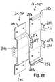
- This component-side connection carrier 25is - as in particular from the Figures 4c and 4d results - plate-like or plate-like design (although this is not absolutely necessary), in the illustrated embodiment, the plate-shaped support 21 is provided with two offset to the remote radio head (RRH) projecting abutment flanges 21 '.
- a second connection carrier 25cooperates, which is preferably releasably connected to the mobile component MK in the form of the explained remote radio head (RRH), wherein in the illustrated embodiment along the upper edge region 25a as the lower edge region 25b of this component-side connection carrier 25th a trough-shaped or U-shaped or groove-shaped holding portion is formed in vertical section.
- the upper and the lower respectively U-shaped or channel-shaped holding portion 25a, 25bis arranged so that the corresponding opening in the trough-shaped or groove-shaped depression of the two holding portions 25a, 25b each other.
- the mentioned connection carrier 21represents the second connection subunit 121.
- boltsare used for the fastening means, which are fixedly attached to the corresponding fastening parts, so that after connection with another part of the fitter only corresponding nuts must be turned on to secure.
- a mobile radio component in the form of a remote radio head (RRH) with its associated and firmly attached to it connection carrier 25can be pushed onto the carrier side mounted connecting plate 21 by this second or antenna side Connecting carrier 25, on which the mobile radio component MK is mounted in the form of the remote radio head (RRH), now with its upper and lower edge portion 25a, 25b on the upper and lower edge portion 21a, 21b of the first connection carrier 21 are pushed laterally can, in which case the U-shaped grooves 25'a and 25'b, the corresponding edges 21a and 21b of the first connection carrier 21 overlap (see FIG. 8b ). On the meaning of this design principle will be discussed later.
- a fixed fixation between the two connecting beams 21, 25can then be carried out by tightening the correspondingly provided fastening means 27, whereby threaded bolts are usually preferably used on the respective parts to be connected, in particular in the form of pressed-in bolts, which are correspondingly preferred hot-dip galvanized steel parts are pressed into the corresponding plate-shaped connecting parts, so that the fitter on site only need to unscrew corresponding nuts on these threaded bolts for fixing the parts.
- first and respectively second connection carrier 21, 25between the thus formed first and second connection unit 121 and 125, a cutting and / or separation point X is formed, which will be discussed below.
- the assembly of a single-sector antenna (with one or more columns) or the mounting of a two or, for example, three sector antennas comprising cellular mobile radio antenna device according to the embodiments showncan be carried out as follows.
- the carrier-side component holding devices 17are opened.
- the clampsare constructed to be adjacent to a clamp base 31 '(see, for example, US Pat FIG. 1b or 4c ), that is, a holding device base 31 comprises two pivotally outwardly or inwardly pivotable holding device arms 33, which can be pivoted outwardly or inwardly respectively about vertical pivot axes 35 running parallel to the mast-shaped support 1.
- these pivot armsare pivoted outwards, and indeed so far that these pivot arms embrace the mast 1' and can be closed after grasping. Subsequently, one or more transverse screws 37 are tightened for fixed fixation of the carrier-side holding device 7 thus formed on the mast-shaped carrier 1.
- the width of the individual mobile radio components MK in the form of the remote radio heads RRHis so great that the mentioned pivoting arms 33 can be opened and pivoted outwardly with the mobile components carrying them to the outside in such a way that the clamps thus formed placed on a mast sideways and can embrace it during closing.
- the other also already pre-assembled mobile radio antennas MAcan be lifted up in a next step via a corresponding crane or traction device, in the embodiment shown the in each case three mobile radio antennas formed in the manner of sector antennas via the respective upper and lower antenna side Holding device 11, the spacers 13 and the carrier-side holding device 7 are interconnected.
- the individual mobile radio antennas as well as the mobile componentscan be mounted one after the other.
- the carrier-side holding devicesthat consist of the same clamp-shaped holding devices that are also used to attach the mobile components to the carrier 1 by opening their pivotable arms (placed on the mast) placed in accordance with proper height and fixed to the support 1 become.
- both the mobile radio components in the form of the remote radio heads RRH and the mobile radio antennasare fastened to the carrier 1 completely separate from one another, the assembly can also be carried out completely independently of one another. Nevertheless, the mobile radio components MK in the form of the remote radio heads RRH are shielded and protected by the individual mobile radio antennas MA when viewed radially from the front (radially relative to the mast-shaped carrier), also visually, the carrying capacities of the mobile radio antennas Antennas and the RRH remote radio heads and the wind forces attaching thereto are only supported on the mast via the separately supporting holding devices.
- fastening meanspreferably in the form of screws, bolts and / or nuts must be solved, about which the first and second connection unit 121, 125 are interconnected. Due to the selected orientation of the threaded bolt whose free ends are very accessible from the side, so that here appropriate nuts can be unscrewed for fastening or turned off to loosen.
- the respective mobile radio component MK in the form of a remote radio head RRH from the distance space (A) with its narrow side of the housing from the distance space (A)can be laterally led out or in more or less parallel to the outside adjacent mobile antenna, which is preferably also aligned with its broad side parallel to the housing broadside of the remote radio head RRH, but this does not necessarily have to be this way.
- the lateral outward movement from the distance space A or, conversely, the inward movement of the remote radio head RRH into the distance space Athus takes place essentially with a horizontal component which runs through the distance space A with lateral offset to the carrier 1, in particular to the mast 1 '.
- the disassembly or assembly movement or change in position of the relevant mobile radio component MK in the form of the remote radio head RRHpreferably takes place with its Narrow side, ie its housing narrow side parallel or in the pivoting and / or displacement plane E, as in FIG. 2a is shown.
- a nextcan be lifted by a crane or lifting device and laterally with its second connection unit with its upper and lower edges 25a, 25b inserted into the receiving grooves 21a, 21b of the first connection unit 121 ,
- the mobile radio component in the form of a remote radio head RRHis initially pre-adjusted and maintained.
- the fastening screwscan then be screwed in and tightened to securely fix the remote radio head RRH by the carrier-side connection carrier 21 with the antenna-side connection carrier 25 firmly connected to each other, in particular screwed.
- connection carrier 21 and 25may also be provided reversed, so that the plate-shaped connection carrier 21, for example, attached to the back of a remote radio head RRH and thus firmly connected, whereas the with the flanged edges provided second connection carrier 25 is then attached via the aforementioned carrier-side component holding means 17 on the carrier 1, for example by means of the clamp-shaped holding means on a mast-shaped carrier 1 '.
- FIGS. 8a to 8cBased on FIGS. 8a to 8c is the structure of the two connecting beams 21, 25, ie the two connecting units 121, 125 shown in more detail. It can be seen that each of the two connection units are provided with laterally folded by 90 ° flaps, which are offset from one another, so that the two parts can be moved laterally, ie parallel to their areal extension into each other. It is on the one side flange 21c (see also Figure 4b and FIG. 8a ) an inwardly projecting mandrel, so in plug-in or Georgiammmensteckraum projecting mandrel 21'e formed automatically engages when running on the counter-flange 25e on the other connection unit in the hole formed there 25f and centered both parts to each other.
- first connection carrier 21opposite to the mentioned side flange 21a, on each of which in the same connection or insertion direction, ie in the same direction as the mandrel 21'e above, screw 21g and 21h and pressed over are held on the first connecting parts 1, as at all parts used, which are preferably made of hot-dip galvanized jet, used as connecting means in the steel parts pressed bolts, then turned on only by fitter on site nuts for fastening or to loosen the parts must be rotated in the opening direction.
- connection units 121, 125are shown.
- connection units 121, 125The basic structure of these connection units 121, 125 is left unchanged as in the previous embodiments.
- the changerelates to an active cooling system such that in the one connection carrier 25 (ie in a connection unit 125), for example, in the central support or plate portion 26a, an electrically driven fan 24 is installed, which in the embodiments shown a perpendicular to the central plate portion 26a has standing rotation axis 24a.
- the middle plate section 26afurthermore has at least one opening or opening 26b in the manner of a window.
- a plurality of openings or openings 22b in the manner of a plurality of windows in the middle parallel spaced plate portion 22a of the other connection carrier 21educated.
- an active cooling systemcan be installed in the distance space B between the two middle plate sections 22a, 26a of the two connection carriers 21, 25 in order to cool, for example, the remote radio head RRH, which may be high during operation Consumes services and thus contributes to a strong warming.
- the active cooling systemcan be counteracted by simple means.
- cooling airmay be blown through the windows 22b, 26b toward the remote radio head RRH.
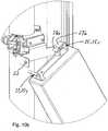
- FIGS. 9aOn the basis of the other FIGS. 9a The following two further modified principles are shown insofar as, for example, a suspension mechanism is used to pre-adjust a newly installed mobile component or for temporary support of a mobile component to be removed in each case in the form of a remote radio head RRH.
- connection carrier 21is used in each case, which is fastened to the carrier-side component holders 17 on the carrier 1.
- the connecting member 21is not plate-shaped in this embodiment and does not connect the upper and axially offset lower carrier-side component holder, but it is for each carrier-side component holder 17, a carrier-side connection carrier 21 is provided on the clamp-shaped carrier-side components Mount 17 may be mounted separately or permanently and permanently connected to it, provided that this connection carrier 21 part of should be clamp-shaped component holding device 17.
- connection carrier 21in plan view fork-shaped, and has two finger- or prong-shaped projecting from the rear support 1 away support arms 21c ( FIG. 9a and 9b ).
- the corresponding second connection carrier 25that is to say the upper side 41, is preferably used in this exemplary embodiment.
- the component-side connection carrier 25is provided, which comprises two different sized bends 25x and 25y, which are designed in the manner of suspension elements.
- the right-hanging hooking element 25ecomprises a larger bend with a front on the top 41 of the mobile component MK slightly tapered hanger portion 27a with a subsequent parallel to the top 41 extending hook portion 27b, spaced from the top to the attachment portion 27c of the hook assembly on the mobile component to lie comes.
- pressed-in boltsare firmly anchored to both support arms 21c, which in the same To project direction freely.
- the mobile componentcan be taken in particular in the lower region and in the illustrated embodiment in the corresponding representation clockwise initially pivoted so far in the lateral direction SR until the mentioned horizontally projecting bolts 22 come to lie in the amount of the corresponding holes in the angles 25x and 25y , Subsequently, the mobile radio component in the form of the remote radio head RRH in its vertical orientation, in which then the holes mentioned in the angles 25x and 25y come to lie horizontally on the first connection carrier 21 laterally, ie in the lateral direction SR further until the corresponding bolts 22 engage in the bores of the second connecting carrier 25. In this situation, the upper bend 25'y then also comes to rest above the upper edge of the second bend 25 "y of the carrier-side connecting carrier 21.
- the mobile radio componenthas already reached its final assembly position
- the corresponding fastening screwsare fixed in order to hold the mobile radio component, with a bottom connection carrier 25 (mounted on the underside of the mobile radio component) likewise pivoting into its final mounting position, in which it comes into contact with a corresponding first connection carrier 21 to screw in between both preferably at corresponding flanges transverse to the mast screws and secure the mobile component.
- FIGS. 9a to 11ashown in the FIGS. 9b to 11b each an enlarged section of the Hanging and fastening mechanism is shown at the top of the mobile component.
- the fastening meanspreferably in the form of threaded bolts and nuts strictly loftenden for fixed fixation of the two connecting part units 121, 125, ie for fixed connection of the two connecting beams 21, 25 transversely to the longitudinal direction of the mobile components MK in the form of remote Radio heads RRH run, in particular preferably horizontally, which is why they are particularly user-friendly each laterally accessible from the mobile component ago to unscrew them on or if necessary, so as to fix the remote radio head RRH fixed or to solve ,
- Dismantlingis done the other way round.
- the corresponding fastening means between the two connection carriers 21, 25, ie between the carrier-side connection carrier 21 and the antenna-side connection carrier 25must be solved to then push out the mobile component something from the anchorage, namely in the direction in which he equipped with the longer Einitatifinger hooking 27a is formed.
- the remote radio head RRH in the in FIG. 10a and 10bshow away Verschwenklage in the lateral direction SR outwards, and again preferably to the pivoting and / or displacement plane E defined by the back of the mobile antenna AM located in front of it FIG. 2a ). In this position shown, the remote radio head RRH can then be raised and lowered by a towing device Carrying out a slight lateral offset next to the connection carrier 21 can be lowered.
- This embodimentalso shows that in each case in the connection region between the remote radio head RRH and the antenna-side carrier 1, a cutting and / or separation point X is formed, which is formed between the carrier-side connection carrier 21 and the antenna-side connection carrier 25. Even with this training, so all remote radio heads RRH can be pulled up during initial assembly in preassembled position with open clamp carriers and then fixed after enclosing the clamp carrier on the mast to mount all remote radio heads RRH together. Subsequently, the mounting of the antennas, as has already been explained in the previous embodiments.
- connection technologyie without the explained with reference to the first embodiment connection carrier
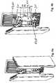
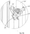
- FIGS. 12a to 12cthe initial situation during the new installation of a mobile radio component in the form of a remote radio head RRH shown (for example, if a mounted remote radio head RRH was previously dismantled at the mast).
- FIGS. 13a to 13dthe intermediate phase is shown, in which the mobile radio component in the form of the remote radio head RRH is pushed laterally with its component-side support means 25 on the carrier-side support means 21, wherein the support means 21 each axially offset lying on the mast with the respective carrier-side component Holding means 17, ie the clamps 17 'are connected, whereas in the FIGS. 14a to 14d the final mounting position is shown.
- the component-side connecting device 25 located at the respective remote radio head RRHalso engages here with a corresponding carrier-side connecting device 21, wherein corresponding preferably pin-shaped axial projections engage corresponding to the recesses on lateral flanges, so that the shape of the remote radio head RRH is supported and held on its two narrow longitudinal sides, as clearly shown in the drawings.
- FIGS. 15a to 15dBased on the following FIGS. 15a to 15d is merely shown that, for example, a single or multi-column mobile antenna MA also on a building side Carrier 1, ie can be fastened to a building 1 "In this case carrier-side holding devices 11 or carrier-side component parts are used both for the mobile radio antenna MA and for the mobile radio component MK in the form of the mentioned remote radio head RRH. Holding devices 17 are used, which are held and anchored, for example, via holes and dowels to be introduced into the building, but the additional construction and holding mechanism attached to them is comparable to the exemplary embodiments explained with respect to the mounting on a mast 1 '.
- the carrier-side connection carrier 21can be attached to the two preferably carrier-side, i. clamp-shaped component holding devices 17 may be attached.
- remote radio heads RRHare to be used that are comparatively small and lightweight, it may be sufficient for only one carrier-side component holder 17 and / or only one component-side holding device 25 to hold and fix the mobile radio carrier.
- Componentis provided, so only one Connection carrier 25 or only a so-called connection unit 125, over which the mobile component is held in the form of the remote radio head RRH.
- the attachment mechanismsmay otherwise be comparable to the illustrated embodiments, for example, based on the embodiment according to FIGS.
- connecting carrier 21 and 25may be secured in its central region with a corresponding holding and carrying device on the mast or on a wall and the cooperating component-side connection carrier also preferably be centrally connected to the mobile component in the form of the remote radio head RRH can.
Landscapes
- Engineering & Computer Science (AREA)
- Computer Networks & Wireless Communication (AREA)
- Support Of Aerials (AREA)
- Telephone Set Structure (AREA)
- Mobile Radio Communication Systems (AREA)
Description
Translated fromGermanDie Erfindung betrifft ein Halterungssystem für eine Mobilfunk-Antenne und eine zugehörige Mobilfunk-Komponente, beispielsweise in Form eines Remote-Radio-Heads nach dem Oberbegriff des Anspruches 1.The invention relates to a mounting system for a mobile radio antenna and an associated mobile radio component, for example in the form of a remote radio head according to the preamble of
Mobilfunk-Antennen sind zwischenzeitlich weit verbreitet. Sie umfassen in der Regel Antennenanordnungen, die beispielsweise nur in einem Sektor oder in mehreren Sektoren, z.B. in drei Sektoren abstrahlen. Bei einer Drei-Sektor-Antenne sind die einzelnen in der Regel vertikal übereinander angeordneten Strahler jeweils in 120°-Richtung um den sie tragenden Mast herum versetzt an diesem befestigt.Mobile antennas are now widely used. They typically include antenna arrays that are, for example, only in one sector or in several sectors, e.g. emit in three sectors. In the case of a three-sector antenna, the individual radiators, which are generally arranged vertically one above the other, are each fixed in the 120 ° direction around the mast carrying them.
Die einzelnen Antennen umfassen dabei üblicherweise eine Vielzahl übereinander angeordneter Strahler, die beispielsweise in einer Polarisation oder vorzugsweise in zwei senkrecht zueinander stehenden Polarisationsebenen strahlen. Häufig sind diese beiden Polarisationsebenen in einem + 45° bzw. - 45° Winkel gegenüber der Horizontalen bzw. Vertikalen angeordnet. Hier wird häufig auch von einer X-Polarisation gesprochen.The individual antennas usually comprise a plurality of radiators arranged one above the other, for example in a polarization or preferably in two mutually perpendicular polarization planes radiate. Frequently, these two polarization planes are arranged in a + 45 ° or - 45 ° angle relative to the horizontal or vertical. Here is often spoken of an X-polarization.
Es kann sich dabei ferner um Mono-Band-, Dual-Band- oder Multi-Band-Antennen handeln, die in mehreren Frequenzbändern senden und/oder empfangen.It may also be mono-band, dual-band or multi-band antennas that send and / or receive in multiple frequency bands.
Schließlich soll auch noch angemerkt sein, dass neben den einspaltigen Antennenarrays häufig auch zwei- oder mehrspaltige Antennenarrays zu Einsatz kommen, wodurch die gesamte Antennenanordnung in der Regel nicht nur unterschiedlich hoch (in Abhängigkeit des gewünschten Antennengewinns) sondern auch relativ breit sein kann.Finally, it should also be noted that in addition to the single-column antenna arrays also two- or multi-column antenna arrays are used, whereby the entire antenna array usually not only different high (depending on the desired antenna gain) but also can be relatively wide.
Die Mobilfunkstationen sind dabei gemäß dem heutigen Standard zunehmend mehr mit weiteren Mobilfunk-Komponenten ausgestattet, d.h. elektronischen Komponenten wie beispielsweise einen Remote-Radio-Head. Dieser kann von der eigentlichen Antenne abgesetzt im Bereich der Mobilfunkstation vorgesehen sein. Häufig wird er ebenfalls bei einer an einen Mast montierten Antenne am Mast selbst befestigt, üblicherweise unterhalb der eigentlichen Antennenanorndung.The mobile stations are increasingly equipped according to the current standard with other mobile components, i. electronic components such as a remote radio head. This can be provided remote from the actual antenna in the mobile station. Often it is also attached to a mast-mounted antenna on the mast itself, usually below the actual Antennenanorndung.
Aus der gattungsbildenden
Jede dieser einzelnen Sektor-Antennen ist über eine obere und eine untere Antennen-Halteeinrichtung an dem Mast befestigt. Die Halteeinrichtungen können dabei schellenförmig ausgestaltet sein.Each of these individual sector antennas is attached to the mast via upper and lower antenna holders. The holding devices can be designed like a clamp.
Ferner ist gemäß dieser Vorveröffentlichung eine in Vertikalrichtung oder überwiegend in Vertikalrichtung verlaufende Trägerplatte vorgesehen, die auch in winkliger Ausrichtung (unter Einstellung eines mechanisch einstellbaren Downtilt-Winkels) am Antenennmast montierbar ist. Die Montage erfolgt dabei mittels eines oben liegenden V-förmigen Abstandhalters, der zwei um eine Horizontalachse verlaufende Abstandshaltearme umfasst, die V-förmig aufeinander zu oder voneinander weg verschwenkt werden können. An den gegenüberliegenden freien Enden des Abstandshalters ist jeweils ein Befestigungsabschnitt, wobei der eine Befestigungsabschnitt an der trägerseitigen Halteeinrichtung am Mast und der dazu gegenüberliegende antennenseitige Befestigungsabschnitt an der Trägerplatte fixiert wird.Furthermore, according to this prior publication, a support plate extending in the vertical direction or predominantly in the vertical direction is provided, which can also be mounted on the antenna mast in an angular orientation (by setting a mechanically adjustable downtilt angle). The assembly is carried out by means of an overhead V-shaped spacer which comprises two extending around a horizontal axis spacer arms, which can be pivoted toward or away from each other in a V-shape. At the opposite free ends of the spacer is in each case a fixing portion, wherein the one fixing portion is fixed to the carrier-side holding means on the mast and the antenna-side fixing portion opposite thereto on the support plate.
Die jeweils tiefer liegende trägerseitige Halteeinrichtung ist direkt mit einer antennenseitigen Halteeinrichtung gelenkig verbunden, also ohne Zwischenschaltung eines Abstandshalters.The respective lower carrier-side holding device is connected directly to an antenna-side holding device articulated, without the interposition of a spacer.
Als Vorteil wird in dieser Vorveröffentlichung herausgestellt, dass auf der dem Mast zugewandten Rückseite einer jeweiligen Trägerplatte eine elektronische Komponente wie beispielsweise eine Remote-Radio-Head (RRH) montiert werden kann, wobei auf der vom Mast weg weisenden Vorderseite der Trägerplatte dann die entsprechende Antenne montiert ist. Die entsprechende elektronische Komponente kann dabei parallel zur Trägerplatte herausgenommen oder hereingeführt oder von unten her parallel zur Trägerplattenebene nach oben in Montagerichtung zugeführt und montiert oder in umgekehrter Richtung demontiert und entnommen werden.An advantage is found in this prior publication that on the mast facing the back of each support plate, an electronic component such as a remote radio head (RRH) can be mounted, on the mast away facing front of the carrier plate then the corresponding antenna is mounted. The corresponding electronic component can be taken out parallel to the support plate or brought in or supplied from below parallel to the support plate plane upwards in the mounting direction and mounted or disassembled and removed in the opposite direction.
Eine Klemmhalterung zur Anbringung einer Tragvorrichtung für eine Mobilfunkantenneneinrichtung an einem Mast ist zudem aus der
Aus der
Befestigungseinrichtungen, wie sie üblicherweise bei einer Antennenmontage benutzt werden, sind beispielsweise aus der Vorveröffentlichung "Modified Product Line of Mounting Parts, Kathrein, 4.1.2011, http://www.kathrein.com/en/mcs/catalogues/download/99811 576_186.pdf [rech.14.12.2012] zu entnehmen. Es handelt sich dabei um übliche Befestigungseinrichtungen.Fastening devices, such as are commonly used in an antenna mounting, for example, from the prior publication "Modified Product Line of Mounting Parts, Kathrein, 4.1.2011, http://www.kathrein.com/en/mcs/catalogues/download/99811 576_186 .pdf [rech.14.12.2012] These are conventional fastening devices.
Aus einer weiteren Vorveröffentlichung, nämlich der RRU3804 Introduction and Hardware Installation, HUAWEI, PDF-Datum 6.4.2008, ftp://static062038250224.dsl.hol.gr/ Download/%CE%9D%CE%AD%CE%BF%CF%82%20%CF%86%CE%AC%CE%BA% CE%B5%CE%BB%CE%BF%CF%82/Texnika/telecom/FOTO%20SITE/huaw ei/HUAWAY%20SERVEY/cd/Presentations/RRU3804%20Introducti on%20and%20Hardware%20Installation.pdf,[rech. 7.12.2012] ist zu entnehmen, dass dort unterschiedlichste Beispiele für Mobilfunk-Komponenten und die Art der Montage beschrieben sind.From another prior release, the RRU3804 Introduction and Hardware Installation, HUAWEI, PDF Date 6/6/2008, ftp://static062038250224.dsl.hol.gr/ Download /% CE% 9D% CE% AD% CE% BF% CF % 82% 20% CF% 86% CE% AC% CE% BA% CE% B5% CE% BB% CE% BF% CF% 82 / Texnika / telecom / PHOTO% 20SITE / huaw ei / HUAWAY% 20SERVEY / cd / Presentations / RRU3804% 20Introducti on% 20and% 20Hardware% 20Installation.pdf, [r. 7.12.2012] it can be seen that the most varied examples of mobile radio components and the type of mounting are described there.
Auf Seite 9 dieser Vorveröffentlichung ist beispielsweise gezeigt, wie an einem Antennenmast eine oder mehrere Mobifunk-Komponenten montiert werden können, wenn in diesem Bereich keine Antenne und insbesondere keine Mobilfunk-Antenne vorgesehen ist.On page 9 of this prior publication, for example, it is shown how one or more Mobifunk components can be mounted on an antenna mast if no antenna and in particular no mobile radio antenna is provided in this area.
Ähnlich ausgestaltete Befestigungseinrichtungen von separaten Mobilfunk-Komponenten oder sonstigen montierbaren Komponenten und Gehäusen an einem Antennenmast sind beispielsweise aus der
Die Verwendung von Mastschellen mit einer Einrastfunktion für eine Ein-Mann-Schnellfixierung in unterschiedlichen Ausführungen ist beispielsweise aus der
Die
Ferner wird auf die
Schließlich soll auch noch auf die
Aufgabe der vorliegenden Erfindung ist es dem gegenüber eine verbesserte Lösung für ein Halterungssystem für eine Mobilfunk-Antenne und eine zugehörige Mobilfunk-Komponente an einem Träger zu schaffen, insbesondere an einem mast- oder wandförmigen Träger.An object of the present invention is to provide an improved solution for a mounting system for a mobile radio antenna and an associated mobile radio component on a carrier, in particular on a mast or wall-shaped carrier.
Die Aufgabe wird erfindungsgemäß entsprechend den im Anspruch 1 angegebenen Merkmalen gelöst. Vorteilhafte Ausgestaltungen der Erfindung sind in den Unteransprüchen angegeben.The object is achieved according to the features specified in
Durch die vorliegende Erfindung wird mit vergleichsweise einfachen Mitteln eine sehr günstige Möglichkeit geschaffen nicht nur eine Mobilfunk-Antenne sondern eine dazugehörige elektronische Komponente, also eine Mobilfunk-Komponente in Form eines ein Remote-Radio-Heads an einem Mast oder beispielsweise an einer Wand eines Gebäudes zu montieren.The present invention provides a very cheap possibility with relatively simple means not only a mobile antenna but an associated electronic component, ie a mobile component in the form of a remote radio head on a mast or, for example, on a wall of a building to assemble.
Erfindungsgemäß ist dazu vorgesehen, dass die entsprechende Antennenanordnung mittels einer Abstandshalteeinrichtung an dem mast- oder wandförmigen Träger so montiert werden kann, dass zwischen der Rückseite der Antenne (in der Regel auf der Rückseite des Reflektors und/oder des Radum) und dem mast- oder wandseitigen Träger ein Abstandsraum entsteht, in welchem der Remote-Radio-Head (RRH) ebenfalls montiert werden kann. Erfindungsgemäß wird der Remote-Radio-Head (RRH) allerdings völlig von der Mobilfunk-Antenne und deren Drahtkonstruktion getrennt montiert, d.h. eigenständig durch eigene Befestigungsmittel an dem mast- oder wandförmigen Träger.According to the invention it is provided that the corresponding antenna arrangement can be mounted by means of a spacer device on the mast or wall-shaped support that between the back of the antenna (usually on the back of the reflector and / or the Radum) and the mast or wall-side support creates a distance space in which the Remote Radio Head (RRH) can also be mounted. However, according to the invention, the Remote Radio Head (RRH) is mounted completely separate from the mobile antenna and its wire construction, i. independently by their own fasteners on the mast or wall-shaped carrier.
Dies führt letztlich dazu, dass auch auf eine gemeinsame Trägerplatte (vergleichbar der Ausbildung gemäß dem gattungsbildenden Stand der Technik gemäß der
Im Rahmen der Erfindung ist es dabei möglich den entsprechenden Remote-Radio-Head (RRH) und vor allem die gegebenenfalls mehreren Mobilfunk-Komponenten (beispielsweise eine in zwei oder drei Sektoren oder mehr strahlende Mobilfunk-Antenne) besonders einfach an einem Mast zu befestigen. Denn in diesem Falle kann im Rahmen der Erfindung eine gemeinsame obere und untere am Mast fixierbare Halteeinrichtung verwendet werden, die jeweils in Umfangsrichtung des Mastes zwei oder beispielsweise drei in gleichen Winkelabständen zueinander versetzt liegende Remote-Radio-Heads (RRH) halten kann.Within the scope of the invention, it is possible to fasten the corresponding remote radio head (RRH) and, in particular, possibly several mobile radio components (for example, a mobile radio antenna radiating in two or three sectors or more) to a mast in a particularly simple manner. Because in this case can be used within the scope of the invention, a common upper and lower fixable on the mast holding device, each in the circumferential direction of the mast two or three, for example, at equal angular intervals offset from each other remote radio heads (RRH) can hold.
Dabei kann unter Umständen bereits eine Vormontage derart erfolgen, dass an den bevorzugt schellenförmigen Halteeinrichtungen am Mast nicht nur die eine sondern schon zwei oder gegebenenfalls drei in Umfangsrichtung versetzt liegende Remote-Radio-Heads (RRH) vormontiert und gemeinsam am Mast fixiert werden. Ansonsten kann gegebenenfalls zumindest einer dieser Remote-Radio-Heads (RRH) durch die entsprechende Befestigungseinrichtung am Mast angebracht werden und die anderen Remote-Radio-Heads (RRH) nach montiert werden, und zwar völlig ohne jede Behinderung, da jeder Remote-Radio-Head (RRH) in Draufsicht auf den Träger, in der Regel den mastförmigen Träger, von außen her frei zugänglich ist.Under certain circumstances, a pre-assembly may take place in such a way that not only one but already two or optionally three circumferentially offset remote radio heads (RRH) are pre-assembled on the mast and preferably fixed together on the mast. Otherwise, if necessary, at least one of these Remote Radio Heads (RRH) can be attached to the mast by the corresponding attachment device and the other Remote Radio Heads (RRH) can be mounted without any hindrance, since every remote radio head Head (RRH) in plan view of the carrier, usually the mast-shaped carrier, is freely accessible from the outside.
In einem zweiten Schritt kann dann darüber befindlich die Befestigungseinrichtung mit den Antennen montiert werden.In a second step, the fastening device with the antennas can then be mounted above it.
Ist die gesamte Montage erfolgt, können im Rahmen der Erfindung gleichwohl bei Bedarf auch einzelne Remote-Radio-Heads (RRH) in dem Freiraum zwischen Antenne und mast- oder wandförmigen Träger demontiert werden.If the entire assembly has taken place, individual remote radio heads (RRH) can nevertheless be dismantled in the free space between the antenna and the mast or wall-shaped carrier within the scope of the invention.
Dazu ist erfindungsgemäß vorgesehen, dass die Halteeinrichtung der Remote-Radio-Heads (RRH) eine zusätzliche Schnitt- und/oder Trennstelle mit jeweils einer komponentenseitigen Teileinheit und einer trägerseitigen Teileinheit aufweist. Mit anderen Worten kann ein Remote-Radio-Head (RRH) mit der ihn tragenden komponentenseitigen Teileinheit vom Rest gelöst und dann beispielsweise durch Parallelverschiebung und/oder Verschwenkung bevorzugt parallel zur vertikalen Mastausrichtung oder parallel zu einem wandförmigen Träger (beispielsweise Gebäudewand) entfernt werden, um dann diese Einheit beispielsweise unter Zuhilfenahme einer Zugseileinrichtung auf den Boden herabzulassen. Umgekehrt kann genauso ein entsprechender Remote-Radio-Head (RRH) beispielsweise nach Auswechslung eines defekten Remote-Radio-Heads (RRH) nachgerüstet werden, indem dieser an der entsprechenden Schnitt- und/oder Trennstelle zunächst aufgesetzt und darüber vorgehalten wird, um diesen dann an dieser Schnitt- und/oder Trennstelle durch Festziehen der Befestigungsmittel fest und sicher anzubringen.For this purpose, the invention provides that the holding device of the remote radio heads (RRH) has an additional cutting and / or separation point, each having a component-side subunit and a carrier-side subunit. In other words, a remote radio head (RRH) with the component side unit carrying it can be detached from the rest and then removed, for example by parallel displacement and / or pivoting, preferably parallel to the vertical mast alignment or parallel to a wall-shaped support (eg building wall) then lower this unit, for example with the help of a Zugseileinrichtung on the ground. Conversely, just as a corresponding remote radio head (RRH) can be retrofitted, for example, after replacement of a defective remote radio heads (RRH) by this is first placed on the appropriate cutting and / or separation point and held on it to this then firmly and securely attach to this cutting and / or separation point by tightening the fastener.
Zusammenfassend lässt sich also festhalten, dass sich das erfindungsgemäße Halterungssystem sowohl für Einzelanordnungen als auch für drei Sektoranordnungen von Mobilfunk-Antennen unter Anbringung einer Mobilfunk-Komponente in Form des erwähnten Remote-Radio-Heads am Mast im engen Abstand hinter der jeweiligen Antenne eignet. Dabei ist das erfindungsgemäße Halterungs-System nicht auf eine spezielle Antenne ausgelegt und kann mit einer Vielzahl von Antennen verwendet werden. Die Halterung ist dabei derart ausgeführt, dass im Falle eines Defekts ein Austausch möglich werden kann, ohne die vorgelagerten Antennen zu verstellen oder gar zu demontieren. Dies ist im Rahmen der Erfindung durch zusätzlich vorgesehenen Schnitt- und/oder Trennstellen zwischen einem derartigen Remote-Radio-Head und zugehörigen Teilen der Befestigungseinrichtung sowie der am Antennenmast zurückbleibenden Befestigungseinrichtung realisiert.In summary, it can thus be stated that the mounting system according to the invention is suitable for individual arrangements as well as for three sector arrangements of mobile radio antennas with attachment of a mobile radio component in the form of the aforementioned remote radio head on the mast in close proximity behind the respective antenna. Here is the mounting system of the invention not designed for a specific antenna and can be used with a variety of antennas. The holder is designed such that in the event of a defect replacement can be made without adjusting the upstream antennas or even dismantle. This is realized in the context of the invention by additionally provided cutting and / or separation points between such a remote radio head and associated parts of the fastening device and the fastening device remaining on the antenna mast.
Eine dem Mast zugeordnete erste Teileinheit und die weitere dem Remote-Radio-Head zugeordnete zweite Teileinheit sind dabei aufeinander abgestimmt und aneinander lösbar befestigt. Nach dem Lösen der Fixierung kann die auszutauschende Komponente nicht nur seitlich hinter der Antenne herausgezogen sondern gegebenenfalls auch herausgeklappt oder herausgedreht oder aus einer Kombination von Bewegungsvorgängen hervorgeholt werden.A first subunit assigned to the mast and the further second subunit assigned to the remote radio head are matched to one another and detachably fastened to one another. After releasing the fixation, the component to be replaced can not only be pulled out laterally behind the antenna, but if necessary, it can also be unfolded or unscrewed or brought out of a combination of movement processes.
Dabei lässt sich die erfindungsgemäße Lösung nicht nur zur Montage an einem Mast sondern beispielsweise auch zur Montage an einer Gebäudewand verwenden.In this case, the solution according to the invention can be used not only for mounting on a mast but also, for example, for mounting on a building wall.
Weitere Vorteile, Einzelheiten und Merkmale ergeben sich nachfolgend aus den anhand von Zeichnungen dargestellten Ausführungsbeispielen. Dabei zeigen im Einzelnen:
- Figur 1a:
- eine Mobilfunk-Antenne mit mehreren Sektor-Antennen und zugehörigen Mobilfunk-Komponenten, montiert an einem Mast in seitlicher Darstellung;
- Figur 1b:
- eine axiale Draufsicht auf das Ausführungsbeispiel gemäß
Figur 1a ; - Figur 2a:
- eine entsprechende Seitendarstellung zu
Figur 1a , jedoch in einer um 30° um den Mast verdreht dargestellten Seitendarstellung; - Figur 2b:
- eine axiale Unteransicht auf das Ausführungsbeispiel gemäß
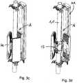
Figur 2a ; - Figur 3a:
- eine perspektivische leicht von oben wiedergegebene Darstellung des Ausführungsbeispiels nach den
Figuren 1a bis 2b ; - Figur 3b:
- eine entsprechende Darstellung zu
Figur 3a , jedoch unter Weglassung der vorderen Sektorantenne, nur unter Wiedergabe der hinteren Sektorantenne; - Figur 3c:
- eine entsprechende Darstellung zu
Figur 3b , jedoch unter Weglassung der linken und vorderen Mobilfunk-Antenne unter Darstellung der jeweils dahinter befindlichen Mobilfunk-Komponenten in Form eines Remote-Radio-Heads (RRH); - Figur 3d:
- eine entsprechende Darstellung zu
Figur 3c , jedoch unter zusätzlicher Weglassung der vorderen Mobilfunk-Komponente in Form des Remote-Radio-Heads (RRH) (nachdem diese Mobilfunk-Komponente an einer Schnitt- und/oder Trennstelle abgebaut bzw. abgezogen wurde); - Figur 4a:
- eine räumliche Darstellung dreier um 120° versetzt liegender Remote-Radio-Heads (RRH), die allesamt an zwei axial versetzt zueinander liegenden schellenförmigen Halteeinrichtungen vormontiert sind, die an einem Mast befestigbar sind;
- Figur 4b:
- eine entsprechende Darstellung zu
Figur 4a , jedoch unter Weglassung der inFigur 4a rechts liegenden Remote-Radio-Heads (RRH) mit zugehörigem rückwärtigen Verbindungsteil; - Figur 4c:
- eine trägerseitige Halteeinrichtung in Plattenform mit den beiden zugehörigen schellenförmigen an einem Mast befestigbaren Halteeinrichtungen;
- Figur 4d:
- eine entsprechende Darstellung zu
Figur 4c , jedoch unter Wiedergabe eines seitlich aufzuschiebenden zweiten Verbindungsträgers, an welchem die Remote-Radio-Heads (RRH) (inFigur 4d nicht gezeigt) befestigt ist; - Figur 4e:
- die entsprechende Darstellung zu
Figur 4d , jedoch unter Wiedergabe des mit dem Verbindungsträger verbundenen Remote-Radio-Heads (RRH); - Figur 5a:
- eine rückwärtige Betrachtung des Remote-RadioHeads (RRH) mit zugehörigem rückwärtigem Verbindungsträger, der erst teilweise auf einem träger- oder mastseitigen Verbindungsträger aufgeschoben ist, der mittels Mastschellen an einem nicht gezeigten Mastträger verankerbar ist;
- Figur 5b:
- eine axiale Draufsicht auf das Ausführungsbeispiel gemäß
Figur 5a ; - Figuren 6a und 7a:
- zwei seitliche Darstellungen einer MobilfunkAntenne vergleichbar
Figur 1a und 2a während des Ein- oder Ausbaus eines einzelnen RemoteRadio-Heads (RRH); - Figuren 6b und 7b:
- eine axiale Draufsicht bzw. Unteransicht bezüglich
Figur 6a und 7a während der Montage oder Demontage eines Remote-Radio-Heads (RRH); - Figuren 8a bis 8c:
- zwei räumliche Darstellungen und eine Seitendarstellung der beiden zusammenwirkenden und aneinander befestigbaren Verbindungsträger, die eine lösbare Schnitt- und/oder Trennstelle zueinander bilden;
- Figuren 8d und 8e:
- zwei Darstellungen eines abgewandelten Ausführungsbeispiels für zwei Verbindungsträger mit einem aktiven integrierten Kühlungssystem;
- Figuren 9a bis 9c:
- verschiedene Darstellungen eines abgewandelten Ausführungsbeispiels bei welchem ein Remote-Radio-Head (RRH) erst eingehängt und dann verschwenkt und befestigt werden kann;
- Figuren 10a bis 10c:
- eine entsprechende Darstellung zu den
Figuren 9a bis 9c während einer weiteren Zwischenphase während des Einhängens eines Remote-Radio-Heads (RRH); - Figuren 11a bis 11c:
- die entsprechende Darstellung nach dem endgültigen Einhäng- und translatorischen Verschiebungsvorgang des Remote-Radio-Heads (RRH) unmittelbar vor oder nach dem Eindrehen der Befestigungsschrauben;
- Figuren 12a bis 12d:
- verschiedene Darstellungen eines abgewandelten Ausführungsbeispiels bei völlig gelöstem Remote-Radio-Head (RRH);
- Figuren 13a bis 13d:
- eine entsprechende Darstellung zu den
Figuren 12a bis 12d jedoch während einer Zwischenphase des Einbaus eines Remote-Radio-Heads (RRH); - Figuren 14a bis 14d:
- entsprechende Darstellungen zu den
Figuren 13a bis 13d jedoch nach endgültigem Erreichen der Fixierposition des Remote-Radio-Heads (RRH) unmittelbar vor oder nach dem Eindrehen der zugehörigen Befestigungsschrauben und; - Figuren 15a bis 15d:
- verschiedene Darstellungen eines Ausführungsbeispiels, bei welchem ein Remote-Radio-Head (RRH) an einer Mauer als Trageinrichtung angebaut ist, vor der dann ebenfalls an der Mauer eine anhand der anderen Ausführungsbeispiele beschriebene Mobilfunk-Antenne den RemoteRadio-Head (RRH) übergreifend oder nach vorne abdeckend montiert ist.
- FIG. 1a
- a mobile radio antenna with multiple sector antennas and associated mobile components, mounted on a mast in side view;
- FIG. 1b
- an axial plan view of the embodiment according to
FIG. 1a ; - FIG. 2a:
- a corresponding page presentation too
FIG. 1a , but in a side view rotated by 30 ° around the mast; - FIG. 2b:
- an axial bottom view of the embodiment according to
FIG. 2a ; - FIG. 3a:
- a perspective slightly reproduced from above representation of the embodiment of the
FIGS. 1a to 2b ; - FIG. 3b:
- a corresponding representation too
FIG. 3a but omitting the front sector antenna, only with reproduction of the rear sector antenna; - FIG. 3c:
- a corresponding representation too
FIG. 3b with the omission of the left and front mobile radio antenna, with the respective mobile radio components behind it being shown in the form of a remote radio head (RRH); - Figure 3d:
- a corresponding representation too
Figure 3c but with the additional omission of the front mobile radio component in the form of the remote radio head (RRH) (after this mobile radio component has been dismantled or disconnected at a cutting and / or separating point); - FIG. 4a
- a spatial representation of three offset by 120 ° remote radio heads (RRH), all of which are pre-mounted on two axially offset from each other clamp-shaped holding devices which are fastened to a mast;
- FIG. 4b:
- a corresponding representation too
FIG. 4a , but omitting the inFIG. 4a right remote radio heads (RRH) with associated rear connection part; - FIG. 4c:
- a carrier-side holding device in the form of plates with the two associated clamp-shaped holding devices which can be fastened to a mast;
- FIG. 4d:
- a corresponding representation too
Figure 4c , but with playback of a laterally aufzuschiebenden second connection carrier on which the Remote Radio Heads (RRH) (inFIG. 4d not shown) is attached; - FIG. 4e:
- the corresponding representation too
FIG. 4d but playing back the remote radio head (RRH) connected to the connection bearer; - FIG. 5a
- a rear view of the Remote RadioHeads (RRH) with associated rear connection carrier, which is only partially pushed onto a carrier or mast side connection carrier, by means of mast clamps a mast carrier, not shown, can be anchored;
- FIG. 5b:
- an axial plan view of the embodiment according to
FIG. 5a ; - FIGS. 6a and 7a:
- two side views of a mobile radio antenna comparable
FIGS. 1a and 2a during the installation or removal of a single Remote Radio Head (RRH); - FIGS. 6b and 7b:
- an axial plan view or bottom view with respect
FIGS. 6a and 7a during assembly or disassembly of a Remote Radio Head (RRH); - FIGS. 8a to 8c:
- two spatial representations and a side view of the two cooperating and fastened to each other connecting carrier, which form a detachable cutting and / or separation point to each other;
- FIGS. 8d and 8e:
- two illustrations of a modified embodiment of two connection carrier with an active integrated cooling system;
- FIGS. 9a to 9c:
- various representations of a modified embodiment in which a remote radio head (RRH) can first be hung and then swiveled and fastened;
- FIGS. 10a to 10c:
- a corresponding representation to the
FIGS. 9a to 9c during another intermediate phase during the insertion of a remote radio head (RRH); - FIGS. 11a to 11c:
- the corresponding representation after the final hooking and translatory displacement operation of the remote radio head (RRH) immediately before or after the fastening screws are screwed in;
- FIGS. 12a to 12d:
- various representations of a modified embodiment with completely solved remote radio head (RRH);
- FIGS. 13a to 13d:
- a corresponding representation to the
FIGS. 12a to 12d however, during an intermediate phase of installing a Remote Radio Head (RRH); - FIGS. 14a to 14d:
- corresponding representations to the
FIGS. 13a to 13d however, after finally reaching the fixation position of the remote radio head (RRH) immediately before or after screwing in the associated fixing screws and; - FIGS. 15a to 15d:
- various representations of an embodiment in which a remote radio head (RRH) is mounted on a wall as a support device, in front of then also on the wall a described with reference to other embodiments mobile radio antenna the Remote Radio Head (RRH) across or after is mounted front covering.
Nachfolgend wird auf ein erstes Ausführungsbeispiel Bezug genommen.Hereinafter, reference is made to a first embodiment.
In
An diesem mastseitigen Träger 1 ist in 120° versetzt liegender Ausrichtung in Azimut-Richtung jeweils eine Mobilfunk-Antenne MA (beispielsweise eine einspaltige Mobilfunk-Antenne) angeordnet, und zwar mit einem die einzelnen Strahler schützenden Radom 5. Die Mobilfunk-Antennen 3 sind in ihrer Längserstreckung im Wesentlichen in Vertikalrichtung oder in der Regel mit überwiegender vertikaler Ausrichtung am Mast moniert.A mobile radio antenna MA (for example a single-column mobile radio antenna) is arranged at 120 ° offset in the azimuth direction on this mast-
Wie bereits aus der Draufsicht gemäß
Ergänzend zu dieser oberen trägerseitigen Halteeinrichtung in Form der trägerseitigen Schellenbefestigung 7' ist eine unten liegende Schellenbefestigung 7' vorgesehen, worüber die jeweilige Antenne MA eher in ihrem oberen sowie unteren Längserstreckungs-Bereich gegenüber dem Mast 1' abgestützt und gehalten ist.In addition to this upper carrier-side holding device in the form of the carrier-side clamp attachment 7 'is a lower clamp attachment 7' is provided, over which the respective antenna MA is rather supported and held in its upper and lower longitudinal extension region relative to the mast 1 '.
Jede der Mobilfunk-Antennen MA weist bevorzugt an ihrem oberen wie unteren Ende bevorzugt in Verlängerung ihrer Rückseite einen Befestigungsabschnitt 11' auf, der allgemein auch als antennenseitige Halteeinrichtung 11 bezeichnet wird.Each of the mobile radio antennas MA preferably has at its upper and lower end, preferably in extension of its rear side, a fastening section 11 ', which is generally also referred to as an antenna-
Grundsätzlich könnte eine einzelne Mobilfunk-Antenne über ihre beiden in Vertikalrichtung versetzt liegenden antennenseitigen Halteeinrichtungen 11 direkt an den beiden am Mast in Vertikalrichtung versetzt liegenden trägerseitigen Halteeinrichtungen 7 angebracht und fest montiert werden.In principle, a single mobile radio antenna could be mounted directly on the two carrier elements 7, which are offset in the vertical direction on the mast in the vertical direction, via its two antenna-
Zur optisch ansprechenden und von außen möglichst nicht sichtbaren Unterbringung der erwähnten Mobilfunk-Komponente MK in Form des Remote-Radio-Heads RRH wird jedoch eine Halteanordnung verwendet, bei der für die Mobilfunk-Antenne MA ein größerer Abstandsraum A zwischen der Rückseite der jeweiligen Mobilfunk-Antenne und dem Träger 1 geschaffen wird. Dazu ist entweder die trägerseitige Halteeinrichtung 7 und/oder die antennenseitige Halteeinrichtung 11 mit größerem radialen Überstand ausgebildet, wodurch ein Abstandshalter gebildet ist, der Teil der entsprechenden Halteeinrichtung sein kann, oder aber es ist ein separater Abstandshalter 13 vorgesehen, der zum einen an der trägerseitigen Halteeinrichtung 7 und zum andern an der antennenseitigen Halteeinrichtung 11 fest anbringbar ist.However, a holding arrangement is used for the visually appealing and externally as far as possible not visible accommodation of the mentioned mobile radio component MK in the form of the remote radio head RRH, in which for the mobile radio antenna MA a larger distance space A between the back of the respective mobile radio Antenna and the
Im gezeigten Ausführungsbeispiel ist die Verbindungstechnik am oberen Ende der Mobilfunk-Antenne MA wie am unteren Ende identisch aufgebaut. Im Falle eines voreinstellbaren mechanischen Absenkwinkels könnte gegebenenfalls die radiale Länge der Abstandshalter unterschiedlich sein, d.h. die radiale Erstreckung z.B. des oberen Abstandshalters größer sein als des unteren. Möglich wäre auch, dass ähnlich wie im gattungsbildenden Stand der Technik auf den unteren (oder oberen) Abstandshalter verzichtet wird, wenn der obere (oder untere) Abstandshalter ausreichend in seiner radialen Länge bemessen ist.In the exemplary embodiment shown, the connection technology at the upper end of the mobile radio antenna MA is constructed identically as at the lower end. Optionally, in the case of a presettable mechanical drop angle, the radial length of the spacers could be different, i. the radial extent e.g. of the upper spacer be greater than the lower one. It would also be possible, as in the generic state of the art, to dispense with the lower (or upper) spacer if the upper (or lower) spacer is dimensioned sufficiently in its radial length.
Im gezeigten Ausführungsbeispiel sind nunmehr die Mobilfunk-Komponenten Merkmalskombination hier in Form der Remote-Radio-Heads RRH in dem erwähnten Abstandsraum A untergebracht. Dabei sind die Remote-Radio-Heads (RRH) jedoch von den Mobilfunkantennen MA und deren Befestigungseinrichtung und -mittel völlig getrennt und separat an dem Träger 1, d.h. in dem gezeigten Ausführungsbeispiel am mastförmigen Träger 1 befestigt. Dazu können die trägerseitigen Komponenten-Halteeinrichtungen 17 in Form von Schellenbefestigungen 17' (siehe
Die Befestigung der zugehörigen Remote-Radio-Heads (RRH) an den trägerseitigen Komponenten-Halteeinrichtungen 17 erfolgt im gezeigten Ausführungsbeispiel nach den
Dieser komponentenseitige Verbindungsträger 25 ist - wie sich insbesondere aus den
Wie insbesondere aus den
Eine feste Fixierung zwischen den beiden Verbindungsträgern 21, 25 kann dann letztlich durch Festziehen der entsprechend vorgesehenen Befestigungsmittel 27 erfolgen, wobei üblicherweise an den jeweils einen zu verbindenden Teilen Gewindebolzen bevorzugt verwendet werden, und zwar insbesondere in Form von eingepressten Bolzen, die in entsprechenden, bevorzugt feuerverzinkten Stahlteilen in den entsprechenden plattenförmigen Verbindungsteilen eingepresst sind, so dass die Monteur vor Ort lediglich noch entsprechende Muttern auf diese Gewindebolzen zur Fixierung der Teile aufdrehen muss.A fixed fixation between the two connecting
Durch die beiden parallel zueinander liegenden im gezeigten Ausführungsbeispiel plattenähnlichen ersten und jeweils zweiten Verbindungsträger 21, 25 wird zwischen der so gebildeten ersten und zweiten Verbindungseinheit 121 und 125 eine Schnitt- und/oder Trennstelle X gebildet, auf die nachfolgend noch eingegangen wird.By the two mutually parallel plate-like in the embodiment shown first and respectively
Die Montage einer Ein-Sektor-Antenne (mit einer oder mehreren Spalten) oder die Montage einer zwei oder beispielsweise drei etc. Sektorantennen umfassenden Mobilfunk-Antenenneinrichtung entsprechend den gezeigten Ausführungsbeispielen kann dabei wie folgt vorgenommen werden.The assembly of a single-sector antenna (with one or more columns) or the mounting of a two or, for example, three sector antennas comprising cellular mobile radio antenna device according to the embodiments shown can be carried out as follows.
Zunächst wird an dem Mast 1' über eine geeignete Zug- und Hebeeinrichtung beispielsweise die eine oder die mehreren vorzugsweise schon vormontierten Mobilfunk-Komponenten MK in Form der Remote-Radio-Heads (RRH) parallel zum Mast 1' nach oben angehoben, und zwar bei noch geöffneten Schellenbefestigungen 17'. Mit anderen Worten sind die trägerseitigen Komponenten-Halteeinrichtungen 17 geöffnet. Dazu sind die Schellen so konstruiert, dass sie neben einer Schellenbasis 31' (siehe beispielsweise
Nachdem die Mobilfunk-Komponenten MK in Form der Remote-Radio-Heads RRH so vormontiert sind, können in einem nächsten Arbeitsschritt über eine entsprechende Kran- oder Zugeinrichtung die weiteren ebenfalls bereits vormontierten Mobilfunk-Antennen MA nach oben gehoben werden, wobei im gezeigten Ausführungsbeispiel die jeweils drei nach Art von Sektorantennen gebildeten Mobilfunk-Antennen über die jeweils obere und untere antennenseitige Halteeinrichtung 11, die Abstandshalter 13 und die trägerseitige Halteeinrichtung 7 miteinander verbunden sind. Ebenso könne aber auch die einzelnen Mobilfunk-Antennen wie aber auch die Mobilfunk-Komponenten nacheinander montiert werden.After the mobile radio components MK are preassembled in the form of the remote radio heads RRH, the other also already pre-assembled mobile radio antennas MA can be lifted up in a next step via a corresponding crane or traction device, in the embodiment shown the in each case three mobile radio antennas formed in the manner of sector antennas via the respective upper and lower antenna
Auch hier können die trägerseitigen Halteeinrichtungen, die aus den gleichen schellenförmigen Halteeinrichtungen bestehen, die auch zur Befestigung der Mobilfunk-Komponenten am Träger 1 verwendet werden durch Öffnen ihrer verschwenkbaren Arme (auf den Mast) in entsprechend richtiger Höhe aufgesetzt und an dem Träger 1 fest montiert werden.Again, the carrier-side holding devices that consist of the same clamp-shaped holding devices that are also used to attach the mobile components to the
Da wie erläutert sowohl die Mobilfunk-Komponenten in Form der Remote-Radio-Heads RRH als auch die Mobilfunk-Antennen völlig getrennt voneinander am Träger 1 befestigt werden, kann auch die Montage völlig unabhängig voneinander durchgeführt werden. Gleichwohl sind die Mobilfunk-Komponenten MK in Form der Remote-Radio-Heads RRH durch die einzelnen Mobilfunk-Antennen MA bei radialer Betrachtung von vorne her (radial bezogen auf den mastförmigen Träger) abgeschirmt und geschützt, auch optisch, wobei die Tragkräfte der Mobilfunk-Antennen und der Remote-Radio-Heads RRH sowie die daran ansetzenden Windkräfte jeweils nur über die sie separat tragenden Halteeinrichtungen am Mast abgestützt sind.Since, as explained, both the mobile radio components in the form of the remote radio heads RRH and the mobile radio antennas are fastened to the
Sollte ein einzelner Remote-Radio-Head RRH aus welchen Gründen auch immer ausfallen und/oder ersetzt werden müssen, so ist dies problemlos dadurch möglich, weil die erwähnten Mobilfunk-Komponenten MK in Form des Remote-Radio-Heads RRH mit dem Träger 1 letztlich über eine erste und zweite Verbindungseinheit 121, 125 unter Ausbildung einer dazwischen liegenden Schnitt- und/oder Trennstelle verbunden sind. Mit andern Worten müssen in diesem Falle die bevorzugt schellenförmigen trägerseitigen Komponenten-Halteeinrichtungen 17 am Mast 1 nicht gelöst werden.Should a single remote radio head RRH fail for whatever reason and / or have to be replaced, this is easily possible because the mentioned mobile radio components MK in the form of the remote radio head RRH with the
Ebenso ist es nicht notwendig, dass möglicherweise auf der Rückseite der einzelnen Mobilfunkkomponenten vorgesehene Befestigungsmittel wie Schrauben gelöst werden müssen, um einen Remote-Radio-Head RRH vom Mast abzubauen. Durch diese Lösung wird vermieden, dass von der rückwärtigen Seite nur sehr schlecht zugängliche Befestigungsmittel gelöst oder festgezogen werden müssen.Likewise, it is not necessary that any fasteners provided on the back side of the individual mobile radio components, such as screws, have to be loosened in order to detach a remote radio head RRH from the mast. This solution avoids that from the rear side only very difficult to access fasteners must be solved or tightened.
Im gezeigten Ausführungsbeispiel müssen lediglich die Befestigungsmittel, vorzugsweise in Form von Schrauben, Schraubenbolzen und/oder -muttern gelöst werden, worüber die erste und zweite Verbindungseinheit 121, 125 miteinander verbunden sind. Durch die gewählte Ausrichtung der Gewindebolzen sind deren freie Enden sehr gut von der Seite her zugänglich, so dass hier ohne Probleme entsprechende Muttern zum Befestigen aufgedreht oder zum Lösen abgedreht werden können.In the embodiment shown, only the fastening means, preferably in the form of screws, bolts and / or nuts must be solved, about which the first and second connection unit 121, 125 are interconnected. Due to the selected orientation of the threaded bolt whose free ends are very accessible from the side, so that here appropriate nuts can be unscrewed for fastening or turned off to loosen.
Nach dem Lösen dieser Schrauben, d.h. bevorzugt der in die Befestigungsteile eingepresst gehaltenen Schraubbolzen aufgedrehten Muttern wird die insoweit schon gelöste und nunmehr nicht mehr fixierte Mobilfunk-Komponente in Form eines Remote-Radio-Heads RRH aber gleichwohl immer noch in ihrer Lage gehalten, da die mit der zugehörigen Mobilfunk-Komponente MK fest verbundene plattenförmige zweite Verbindungseinheit 125 noch durch die umgebördelten Randabschnitte 25a und 25b am ersten trägerseitigen Verbindungsträger 21, also an der ersten Verbindungseinheit 121 gehalten wird. Dies eröffnet die Möglichkeit, dass erst nach dem Lösen aller Schrauben und Verbindungsmittel als nächstes die so schon gelöste und entsprechend vorbereitete Mobilfunk-Komponente in Form eines Remote-Radio-Heads RRH seitlich, d.h. bevorzugt parallel zur Schnittflächenebene, d.h. parallel zum Mast 1' und damit parallel zur Ebene der beiden parallel aneinander liegenden Verbindungseinheiten 121, 125 seitlich aus der Befestigungseinrichtung herausgeschoben werden kann, also in Seitenrichtung SR, wie dies zudem in zwei unterschiedlichen Seitendarstellungen gemäß Figur 6a und 7a zum einen und in einer axialen Draufsicht gemäß
Nachdem ein entsprechender Remote-Radio-Head RRH entfernt ist, kann eine nächste durch eine Kran- oder Hebeeinrichtung angehoben und seitlich mit ihrer zweiten Verbindungseinheit mit ihrem oberen und ihren unteren Rand 25a, 25b in die Aufnahmenuten 21a, 21b der ersten Verbindungseinheit 121 eingeschoben werden. Dadurch ist die Mobilfunk-Komponente in Form eines Remote-Radio-Heads RRH zunächst einmal vorjustiert und vorgehalten. In einem nächsten Schritt können dann die Befestigungsschrauben eingedreht und festgezogen werden, um den Remote-Radio-Head RRH sicher zu fixieren, indem der trägerseitige Verbindungsträger 21 mit dem antennenseitigen Verbindungsträger 25 fest miteinander verbunden, insbesondere verschraubt ist.After a corresponding remote radio head RRH is removed, a next can be lifted by a crane or lifting device and laterally with its second connection unit with its upper and
Grundsätzlich können die beiden erläuterten Verbindungsträger 21 und 25 (also die beiden Verbindungseinheiten 121 und 125) auch vertauscht vorgesehen sein, so dass der plattenförmige Verbindungsträger 21 beispielsweise an der Rückseite eines Remote-Radio-Heads RRH befestigt und damit fest verbunden ist, wohingegen der mit den umgebördelten Rändern versehene zweite Verbindungsträger 25 dann über die erwähnten trägerseitigen Komponenten-Halteeinrichtungen 17 am Träger 1 befestigt ist, beispielsweise mittels der schellenförmigen Halteeinrichtungen an einem mastförmigen Träger 1'.Basically, the two explained
Anhand der
Ferner sind an diesem ersten Verbindungsträger 21 gegenüberliegend zu dem erwähnten Seitenflansch 21a zwei kleinere Seitenflansche 21c und 21d vorgesehen, an denen jeweils in gleicher Verbindungs- oder Einsteckrichtung, also in gleicher Richtung wie der Dorn 21'e vorstehend, Schraubbolzen 21g und 21h eingepresst und darüber am ersten Verbindungsteile 1 gehalten sind, wie überhaupt an allen verwendeten Teilen, die bevorzugt aus feuerverzinktem Strahl gefertigt sind, als Verbindungsmittel in die Stahlteile eingepresste Bolzen verwendet werden, auf die dann nur noch von Monteur vor Ort Muttern zum Befestigen aufgedreht oder zum Lösen der Teile in Öffnungsrichtung gedreht werden müssen. Beim Zusammenfügen der beiden Verbindungsträger 21, 25 greift dann nicht nur der erwähnte Dorn 21'e in die mittlere Öffnung 25f des Seitenflansches 25e des zweiten Verbindungsträgers ein, sondern die erwähnten beiden Gewindebolzen 21g und 21h greifen in die entsprechenden Bohrungen 25'c bzw. 25'd der jeweils gegenüberliegenden Laschen 25c und 25d ein, durchragen also diese Öffnungen (die bevorzugt zum Ausgleich von Toleranzfehlern als leichte Langlöcher ausgebildet sind), so dass der Monteur anschließend nur noch auf die überstehenden Teile der Gewindebolzen zur Fixierung der erwähnten Muttern aufdrehen muss. Daraus ist auch zu ersehen, dass die Befestigungselemente quer und damit im Wesentlichen horizontal gegenüber dem Mast ein- und ausgedreht werden müssen, also von der Seite her stets gut zugänglich sind.Furthermore, two
Ferner wird auch noch auf die beigefügten
Der Grundaufbau dieser Verbindungseinheiten 121, 125 ist wie in den vorausgegangenen Ausführungsbeispielen unverändert belassen. Die Änderung betrifft ein aktives Kühlungssystem derart, dass in dem einen Verbindungsträger 25 (also in der einen Verbindungseinheit 125) beispielsweise in dem mittleren Träger- oder Plattenabschnitt 26a ein elektrisch antreibbarer Lüfter 24 eingebaut ist, der in den gezeigten Ausführungsbeispielen eine senkrecht zum mittleren Plattenabschnitt 26a stehende Rotationsachse 24a aufweist. Der mittlere Plattenabschnitt 26a weist dazu ferner zumindest eine Öffnung oder Durchbrechung 26b nach Art eines Fensters auf.The basic structure of these connection units 121, 125 is left unchanged as in the previous embodiments. The change relates to an active cooling system such that in the one connection carrier 25 (ie in a connection unit 125), for example, in the central support or
An dem im Abstand dazu parallel liegenden mittleren Plattenabschnitt 22a des anderen Verbindungsträgers 21 (also der Verbindungseinheit 121) sind im gezeigten Ausführungsbeispiel eine Vielzahl von Öffnungen oder Durchbrechungen 22b nach Art von einer Vielzahl von Fenstern ausgebildet. Dies eröffnet die Möglichkeit, dass hierüber in dem Abstandsraum B zwischen den beiden mittleren Plattenabschnitten 22a, 26a der beiden Verbindungsträger 21, 25 eine aktives Kühlsystem eingebaut sein kann, um beispielsweise den Remote-Radio-Head RRH zu kühlen, die unter Umständen im Betrieb hohe Leistungen verbraucht und damit zu einer starken Erwärmung beiträgt. Durch das aktive Kühlungssystem kann dem mit einfachen Mitteln entgegengewirkt werden. Während des Betriebs des Lüfters 24 kann kühlende Luft durch die Fenster 22b, 26b in Richtung Remote-Radio-Head RRH geblasen werden.In the embodiment shown in the embodiment, a plurality of openings or openings 22b in the manner of a plurality of windows in the middle parallel spaced
Anhand der weiteren
Auch in diesem Falle wird jeweils ein Verbindungsträger 21 verwendet, der mit den trägerseitigen Komponenten-Halterungen 17 am Träger 1 befestigt ist. Allerdings ist der Verbindungsträger 21 bei diesem Ausführungsbeispiel nicht plattenförmig gestaltet und verbindet dabei nicht die obere und axial dazu versetzt liegenden untere trägerseitige Komponenten-Halterung, sondern es ist für jede trägerseitige Komponenten-Halterung 17 ein trägerseitiger Verbindungsträger 21 vorgesehen, der an der schellenförmigen trägerseitigen Komponenten-Halterung 17 separat montiert oder mit ihr fest und dauerhaft verbunden sein kann, sofern dieser Verbindungsträger 21 Teil der schellenförmigen Komponenten-Halteeinrichtung 17 sein soll.Also in this case, a
Bei diesem Ausführungsbeispiel gemäß den
An der Mobilfunk-Komponente MK in Form des Remote-Radio-Heads RRH ist in diesem Ausführungsbeispiel bevorzugt an deren Oberseite 41 der entsprechende zweite Verbindungsträger 25, d.h. der komponentenseitige Verbindungsträger 25 vorgesehen, der zwei unterschiedlich groß dimensionierte Abwinklungen 25x und 25y umfasst, die nach Art von Einhängeelementen ausgebildet sind.At the mobile radio component MK in the form of the remote radio head RRH, the corresponding
Insbesondere das in
Der entsprechende Montage- und Bewegungsablauf ist anhand der
Daraus ist auch ersichtlich, dass die Befestigungsmittel vorzugsweise in Form von Gewindebolzen und drauf aufzudrehenden Muttern zur festen Fixierung der beiden Verbindungsteileinheiten 121, 125, also zur festen Verbindung der beiden Verbindungsträger 21, 25 quer zur Längsrichtung der Mobilfunk-Komponenten MK in Form des Remote-Radio-Heads RRH verlaufen, insbesondere also bevorzugt horizontal, weshalb sie besonders bedienerfreundlich jeweils seitlich von der Mobilfunk-Komponente her zugänglich sind, um sie ein- oder bei Bedarf auszuschrauben, um also den Remote-Radio-Head RRH fest zu fixieren oder zu lösen.It can also be seen that the fastening means preferably in the form of threaded bolts and nuts aufzudrehenden for fixed fixation of the two connecting part units 121, 125, ie for fixed connection of the two connecting
Die Demontage erfolgt auf umgekehrtem Weg. Die entsprechenden Befestigungsmittel zwischen den beiden Verbindungsträgern 21, 25, d.h. zwischen dem trägerseitigen Verbindungsträger 21 und dem antennenseitigen Verbindungsträger 25 müssen gelöst werden, um dann die Mobilfunkkomponente etwas aus der Verankerung herauszuschieben, nämlich in die Richtung, in welche er mit dem längeren Einhängefinger ausgestatteten Einhängeelement 27a ausgebildet ist. Anschließend kann der Remote-Radio-Head RRH in die in
Auch dieses Ausführungsbeispiel zeigt, dass jeweils in dem Verbindungsbereich zwischen dem Remote-Radio-Head RRH und dem antennenseitigem Träger 1 eine Schnitt- und/oder Trennstelle X ausgebildet ist, die zwischen dem trägerseitigen Verbindungsträger 21 und dem antennenseitigen Verbindungsträger 25 ausgebildet ist. Auch bei dieser Ausbildung können also alle Remote-Radio-Heads RRH bei der Erst-Montage in vormontierter Position bei geöffneten Schellenträgern hochgezogen und dann nach dem Umschließen des Schellenträgers am Mast fixiert werden, um alle Remote-Radio-Heads RRH gemeinsam zu montieren. Anschließend erfolgt die Montage der Antennen, wie dies bereits bei den vorausgegangenen Ausführungsbeispielen erläutert wurde. Sofern später ein Remote-Radio-Head RRH durch einen anderen ersetzt werden soll oder muss, kann dies ohne Demontage der Mobilfunk-Antennen erfolgen, indem der entsprechende Remote-Radio-Head Remote-Radio-Head, wie erläutert, teilweise in seine parallel zum Mast verlaufende Ebenen und damit auch parallel zur Rückseite der davor sitzenden Mobilfunk-Antennen verschoben und/oder verschwenkt wird.This embodiment also shows that in each case in the connection region between the remote radio head RRH and the antenna-
Anhand der weiteren Ausführungsbeispiele gemäß der
Dabei ist in den
Die an dem jeweiligen Remote-Radio-Head RRH unten liegende komponentenseitige Verbindungseinrichtung 25 greift auch hier mit einer entsprechenden trägerseitigen Verbindungseinrichtung 21 zusammen, wobei entsprechende bevorzugt stiftförmige axiale Vorsprünge entsprechend der Ausnehmungen an seitlichen Flanschen eingreifen, so dass der Form der Remote-Radio-Head RRH an seinen beiden schmalen Längsseiten abgestützt und gehalten ist, wie sich aus den Zeichnungen deutlich ergibt.The component-
Anhand der nachfolgenden
Die verschiedenen Ausführungsbeispiele sind für jenen Fall erläutert worden, dass jeweils zwei träger- oder mastseitige Komponenten-Halteeinrichtungen 17 und insoweit auch zwei trägerseitige Verbindungsträger 21 verwendet werden, an denen beispielsweise die beiden komponentenseitigen Verbindungsträger 25 angreifen. Für den Fall, dass plattenförmige Verbindungsträger verwendet werden, kann der trägerseitige Verbindungsträger 21 an den beiden bevorzugt trägerseitige, d.h. schellenförmigen Komponenten-Halteeinrichtungen 17 befestigt sein.The various exemplary embodiments have been explained for the case in which two carrier-side or mast-side
Dadurch lässt sich eine hohe, auch hohe Windkräfte aufnehmende Traglast sicher an dem Mast oder der Wand abstützen, worüber die gesamte Antennenanordnung mit den Remote-Radio-Heads RRH gehalten ist. Insbesondere aber dann, wenn Remote-Radio-Heads RRH verwendet werden sollen, die vergleichsweise klein und leicht sind, kann es ausreichend sein, dass nur eine trägerseitige Komponenten-Halterung 17 und/oder nur eine komponentenseitige Halteeinrichtung 25 zur Halterung und Fixierung der Mobilfunk-Komponente vorgesehen ist, also auch nur ein Verbindungsträger 25 oder nur eine sogenannte Verbindungseinheit 125, worüber die Mobilfunk-Komponente in Form des Remote-Radio-Heads RRH gehalten ist. Die Befestigungsmechanismen können aber ansonsten vergleichbar den erläuterten Ausführungsbeispielen sein, wobei beispielsweise die anhand des Ausführungsbeispiels nach
Claims (16)
- Retainer system for a mobile-telephony antenna and a mobile-telephony component, the mobile-telephony antenna (MA) being mountable on a mast-shaped or wall-shaped support (1), having the following features:- for the mobile-telephony antenna (MA), the retainer system comprises at least two antenna holding devices (11), which can be mounted on the antenna side and are positioned vertically or predominantly vertically mutually offset, having an upper and a lower antenna holding device (11),- each of the at least two antenna-side antenna holding devices (11) is fixable or fixed directly or indirectly to a support-side antenna holding device (7),- at least one spacer (13) is provided, which is part of at least a support-side antenna holding device (7) or an antenna-side antenna holding device (11) or is mounted as a separate component between the at least one and preferably two support-side and antenna-side antenna holding devices (7, 11),- between the upper and the lower antenna holding device (11, 7) on the one hand and between the support-side holding device (7) and the mobile-telephony antenna (MA) on the other hand, a separating space (A) open in a lateral direction is provided, in which a mobile-telephony component (MK) is mountable or mounted,characterised by the following further features:- the mobile-telephony component (MK) in form of a remote-radio-head (RRH) is fixed on the support side by means of a retainer system, which is separated from the holding devices (11, 7) for the mobile-telephony antenna (MA),- for this purpose, the retainer system comprises at least one support-side mobile-telephony component holding device (17),- the remote-radio-head (RRH) comprises at least one component-side mobile-telephony component holding device (25),- between the support-side mobile-telephony component holding device (17) and the respective component-side mobile-telephony component holding device (25), a pivoting and/or displacement plane (E) is formed, the support-side mobile-telephony component holding device (17) and the respectively associated component-side mobile-telephony component holding device (25) being releasably fixed to one another via the pivoting and/or displacement plane (E), and- when the associated fixing means are released, the mounted remote-radio-head (RRH) can be removed from the separating space (A) in the lateral direction (SR), by way of the component-side mobile-telephony component holding device (25), by displacement and/or pivoting and/or rotation, leaving behind the support-side mobile-telephony component holding device (17), even while the mobile-telephony antenna (MA) is still mounted.
- Retainer system according to claim 1,characterised in that the mobile-telephony component holding device (17) which can be mounted on the support (1; 1', 1") corresponds to the support-side antenna holding device (7).
- Retainer system according to either claim 1 or claim 2,characterised by the following features:- two support-side mobile-telephony component holding devices (17) arranged at an axial distance from one another are provided,- a connection support (21) in the form of a first connection sub-unit (121) is provided between the two support-side mobile-telephony component holding devices (17),- the component-side mobile-telephony component holding device (25) which is connected to the remote-radio-head (RRH) is provided with a second connection support (25) in the form of a second connection sub-unit (125),- the first and second connection sub-unit (121, 125) are fixed or fixable to one another by means of screws.
- Retainer system according to claim 3,characterised in that the pivoting and/or displacement plane (E) are formed between the two connection supports (21, 25) or the two connection sub-units (121, 125) and extend through the separating space (A) in the lateral direction (SR), andin that the two connection supports (21, 25), in particular in the form of the connection sub-units (121, 125) can be fixed to and released from one another at the pivoting and/or displacement plane (E).
- Retainer system according to either claim 3 or claim 4,characterised in that the support-side connection support (21) or the first connection sub-unit (121) comprises an upper and a lower edge portion (21a, 21b), andin that the component-side connection support (25) or the second connection sub-unit (125) comprises an upper and a lower turned-up edge portion (25a, 25b) forming a channel or groove (25'a, 25'b), in which the upper and lower edge portions (21a, 12b) of the support-side connection support (21) or the support-side connection sub-unit (121) respectively engage, whereby the component-side connection support (25) or the second connection unit (125) can be displaced, along with the remote-radio-head (RRH) fixed thereto, on the upper and lower edges (21, 21b) of the support-side connection support (21) or of the first connection sub-unit (121) when the fixing means are released.
- Retainer system according to either claim 3 or claim 4,characterised in that the component-side connection support (21) or the second connection sub-unit (121) comprises an upper and a lower edge portion (21a, 21b), andin that the support-side connection support (25) or the first connection sub-unit (125) comprises an upper and a lower turned-up edge portion (25a, 25b) forming a channel or groove (25'a, 25'b), in which the upper and lower edge portions (21, 21b) of the component-side connection support (21) or of the second connection sub-unit (121) respectively engage, whereby the support-side connection support (25) or the second connection unit (125) can be displaced, along with the remote-radio-head (RRH) fixed thereto, on the upper and lower edges (21a, 21b) of the component-side connection support (21) or of the second connection sub-unit (121) when the fixing means are released.
- Retainer system according to either claim 1 or claim 2,characterised in that a separate connection support (21) is installed in each case both on the first and on the second support-side component holding device (17), a remote-radio-head (RRH) being mountable or mounted, by way of the component-side second connection support (25) or connection units (125) thereof, on the two mutually spaced connection supports (21).
- Retainer system according to claim 7,characterised in that the at least two component-side connection supports (25) are pre-mounted on an upper end face and/or on a rear wall of a remote-radio-head (RRH).
- Retainer system according to either claim 7 or claim 8,characterised in that the support-side connection support (21) or support-side connection sub-unit (121) and the component-side connection support (25) or component-side connection sub-unit (125) comprise projections or journals which protrude transversely to the longitudinal extension of the remote-radio-head (RRH) and in particular horizontally and which engage in corresponding clearances.
- Retainer system according to claim 3,characterised in that the support-side or the component-side connection support (21, 25) is formed in such a way that during the mounting of a remote-radio-head (RRH) it can, in an intermediate step, be suspended by a suspension mechanism in the region of the upper end thereof on a support-side connection support (21), and subsequently be brought into the final mounting position thereof by pivoting and/or translational displacement, and conversely removed.
- Retainer system according to either claim 9 or claim 10,characterised in that the upper component-side connection support (25) comprises two suspension angles (25d, 25e), via which the remote-radio-head (RRH) is held braced in the mounting position thereof, at least one of the two mounting angles (25d, 25e) comprising an angle portion (27a) which, at the free end thereof, tapers onto the remote-radio-head (RRH).
- Retainer system according to any of claims 1 to 11,characterised in that both the component holding devices (17) and the support-side antenna holding devices (7) can be mounted on the support (1; 1', 1"), which is in the form of a mast-shaped support (1') or a wall-shaped support (1").
- Retainer system according to any of claims 1 to 12,characterised in that an active cooling system is integrated into the region of the pivoting and/or displacement plane (E), preferably in the region of the two connection supports (21, 25) which are releasably fixed to one another or of the two connection sub-units (121, 125).
- Retainer system according to claim 13,characterised in that an electrically driveable ventilator (24) is accommodated in a separating space (B) between two plate portions (22a, 26a) of the two connection supports (21, 25), andin that at least one or more openings or clearances (22b, 26b) are provided transversely to the two connection supports (21, 25), so as to blow the air used for cooling through them by means of the ventilator.
- Retainer system according to either claim 1 or claim 2,characterised in that a support-side component holding device (17) is provided, which is mounted or mountable on the support (1, 1', 1"), andin that a connection support (21) in the form of a first connection sub-unit (121), to which the component side holding device (25) is fixed or fixable as a second connection support (25) in the form of a second connection sub-unit (125) by means of screws, is provided on the support-side component holding device (17), one of the provided remote-radio-head (RRH) being held and fixed on the second connection support (25) or the second connection sub-unit (125).
- Retainer system according to any of claims 1 to 15,characterised in that the housing narrow side of the remote-radio-head (RRH) can be moved and/or pivoted out of the separating space (A) in the lateral direction (SR).
Applications Claiming Priority (2)
| Application Number | Priority Date | Filing Date | Title |
|---|---|---|---|
| DE201210011892DE102012011892A1 (en) | 2012-06-15 | 2012-06-15 | Mounting system for a mobile antenna and a mobile component |
| PCT/EP2013/001755WO2013185925A1 (en) | 2012-06-15 | 2013-06-13 | Retainer system for a mobile-telephony antenna and a mobile-telephony component |
Publications (2)
| Publication Number | Publication Date |
|---|---|
| EP2862233A1 EP2862233A1 (en) | 2015-04-22 |
| EP2862233B1true EP2862233B1 (en) | 2019-09-04 |
Family
ID=48672555
Family Applications (1)
| Application Number | Title | Priority Date | Filing Date |
|---|---|---|---|
| EP13730805.2AActiveEP2862233B1 (en) | 2012-06-15 | 2013-06-13 | Retainer system for a mobile-telephony antenna and a mobile-telephony component |
Country Status (9)
| Country | Link |
|---|---|
| US (1) | US9882260B2 (en) |
| EP (1) | EP2862233B1 (en) |
| KR (1) | KR102047430B1 (en) |
| CN (1) | CN104508903B (en) |
| AU (1) | AU2013276920B2 (en) |
| DE (1) | DE102012011892A1 (en) |
| ES (1) | ES2757840T3 (en) |
| IN (1) | IN2014KN03121A (en) |
| WO (1) | WO2013185925A1 (en) |
Families Citing this family (17)
| Publication number | Priority date | Publication date | Assignee | Title |
|---|---|---|---|---|
| DE102014002169A1 (en)* | 2014-02-19 | 2015-08-20 | Kathrein-Werke Kg | Antenna, in particular mobile radio antenna |
| KR102140293B1 (en) | 2014-02-24 | 2020-08-11 | 주식회사 케이엠더블유 | Multi band antenna device |
| DE102016112701A1 (en) | 2016-07-11 | 2018-01-11 | Kathrein-Werke Kg | Mobile antenna for attachment to a mast or wall support with at least two replaceable amplifier modules |
| WO2018022307A1 (en)* | 2016-07-25 | 2018-02-01 | Commscope Technologies Llc | Integrated cell site sector |
| WO2018111480A2 (en)* | 2016-12-16 | 2018-06-21 | Commscope Technologies Llc | Integrated cell site sector module |
| GB2579977B8 (en)* | 2017-08-15 | 2023-07-19 | Commscope Design & Integration Uk Ltd | Antenna mounting bracket assembly |
| CN107785646A (en)* | 2017-09-07 | 2018-03-09 | 广东通宇通讯股份有限公司 | Antenna system and its antenna mounting device |
| KR102024632B1 (en)* | 2018-10-29 | 2019-09-24 | 현진에스엔티(주) | Joint type Bracket for Fixing Cellular Antenna |
| AT521929B1 (en) | 2018-11-20 | 2021-03-15 | Ms Cns Communication Network Solutions Gmbh | Support structure and antenna mast for mounting cellular radio equipment |
| CN109802220B (en)* | 2018-12-26 | 2020-10-09 | 桂林长海发展有限责任公司 | Install antenna array fast |
| CN111463545A (en)* | 2019-01-18 | 2020-07-28 | 康普技术有限责任公司 | Antenna Mounting Device |
| WO2020159113A1 (en)* | 2019-02-01 | 2020-08-06 | 주식회사 케이엠더블유 | Bracket for supporting wireless communication device and wireless communication device support assembly using same |
| CN111799541B (en)* | 2019-04-08 | 2025-08-05 | 户外无线网络有限公司 | Antenna mounting device |
| CN114552214B (en)* | 2020-11-24 | 2024-12-27 | 华为技术有限公司 | Antenna System |
| US20220285826A1 (en)* | 2021-03-04 | 2022-09-08 | Commscope Technologies Llc | Enclosures for cellular base station assemblies and bracket assemblies for mounting same |
| WO2023250206A1 (en)* | 2022-06-24 | 2023-12-28 | John Mezzalingua Associates, LLC | Universal mount for dense integration of radio remote units |
| US20240178543A1 (en)* | 2022-11-25 | 2024-05-30 | Commscope Technologies Llc | Mounting brackets for mounting multiple antennas to a monopole and related assemblies |
Citations (1)
| Publication number | Priority date | Publication date | Assignee | Title |
|---|---|---|---|---|
| CN201247823Y (en)* | 2008-07-22 | 2009-05-27 | 鼎桥通信技术有限公司 | Antenna subsystem, antenna unit and radio frequency zooming unit |
Family Cites Families (38)
| Publication number | Priority date | Publication date | Assignee | Title |
|---|---|---|---|---|
| US3561712A (en)* | 1969-01-24 | 1971-02-09 | Southern States Inc | Adjustable support device |
| US3821745A (en)* | 1971-08-30 | 1974-06-28 | Cca Electronics | Transmitting antenna employing parasitic end fire directors |
| US3829864A (en)* | 1973-07-18 | 1974-08-13 | D Truskanov | Transmitting stacked aerial |
| US4223315A (en)* | 1975-11-03 | 1980-09-16 | Andrew Alford | Stacked arrays for broadcasting elliptically polarized waves |
| US5707033A (en)* | 1995-12-18 | 1998-01-13 | Holt; Robert J. | Antenna mounting apparatus |
| KR0169700B1 (en)* | 1996-03-21 | 1999-02-01 | 배순훈 | Elevation & azimuth angle control apparatus of satellite broadcasting receiving antenna |
| SE513164C2 (en)* | 1998-03-03 | 2000-07-17 | Allgon Ab | mounting bracket |
| US7106273B1 (en)* | 1998-12-21 | 2006-09-12 | Samsung Electronics Co., Ltd. | Antenna mounting apparatus |
| DE29912906U1 (en) | 1999-07-23 | 1999-12-16 | M-Plan Ingienieurgesellschaft für Mobilfunk mbH, 86368 Gersthofen | Clamp bracket |
| US6268828B1 (en)* | 2000-01-11 | 2001-07-31 | Metawave Communications Corporation | Cylindrical antenna coherent feed system and method |
| US6222504B1 (en)* | 2000-01-14 | 2001-04-24 | Omnipoint Corporation | Adjustable antenna mount with rotatable antenna brackets for PCS and other antennas |
| FR2815477B1 (en)* | 2000-10-16 | 2006-06-16 | Bouygues Telecom Sa | SUPPORTS FOR FASTENING A MATERIAL OF ONE OR MORE RELAY ANTENNAS OF CELLULAR RADIO TELECOMMUNICATION SYSTEMS AND DEVICE FOR ADJUSTING THE ORIENTATION OF SUCH ANTENNA |
| US6677916B2 (en)* | 2000-12-29 | 2004-01-13 | Spx Corporation | Common aperture UHF/VHF antenna |
| US6456258B1 (en)* | 2001-02-06 | 2002-09-24 | Harris Broadband Wireless Access, Inc. | Spring loaded antenna mounting system and method |
| CH695409A5 (en)* | 2001-04-17 | 2006-04-28 | Huber+Suhner Ag | Antenna mount. |
| US20040066353A1 (en)* | 2002-10-03 | 2004-04-08 | Ernest Ehlen Mathias Martin | Antenna mounting methods and apparatus |
| DE20215290U1 (en)* | 2002-10-04 | 2003-04-24 | Snajder, Tomislav, 91466 Gerhardshofen | Radio antenna mounting has unit clamped to mast using three plates, hinges and bolts |
| US6999042B2 (en)* | 2003-03-03 | 2006-02-14 | Andrew Corporation | Low visual impact monopole tower for wireless communications |
| US6914579B2 (en)* | 2003-03-26 | 2005-07-05 | Spx Corporation | Apparatus and method for isolating in-channel FM antennas sharing common aperture space |
| US7253786B1 (en)* | 2003-06-04 | 2007-08-07 | Rocco Logozzo | Reinforced monopole construction |
| US6969034B2 (en)* | 2003-08-07 | 2005-11-29 | Musco Corporation | Enclosure box attachment apparatus, system, and method |
| US7084834B1 (en)* | 2004-03-08 | 2006-08-01 | Hopkins Steven R | Mounting assembly for sectorized antennas |
| TWI294948B (en)* | 2006-07-13 | 2008-03-21 | Accton Technology Corp | Object fixer |
| CN201001113Y (en) | 2006-12-21 | 2008-01-02 | 华为技术有限公司 | A connector and a radio frequency device integrated with the connector |
| US8729446B2 (en)* | 2007-06-29 | 2014-05-20 | Orion Energy Systems, Inc. | Outdoor lighting fixtures for controlling traffic lights |
| CN101753180A (en)* | 2008-12-19 | 2010-06-23 | 华为技术有限公司 | Holding rod installation part |
| WO2010135862A1 (en)* | 2009-05-26 | 2010-12-02 | 华为技术有限公司 | Antenna device |
| CN201528038U (en)* | 2009-07-30 | 2010-07-14 | 京信通信系统(中国)有限公司 | Integrated antenna and integrated radio frequency device |
| CN201466222U (en)* | 2009-08-06 | 2010-05-12 | 中国移动通信集团公司 | Antenna subsystem applied to three-frequency-band networking |
| CN102044736B (en)* | 2009-10-14 | 2015-05-20 | 中兴通讯股份有限公司 | Radio remote unit |
| BR112012010063A2 (en)* | 2009-10-30 | 2016-05-31 | Huawei Tech Co Ltd | concentrating base station |
| WO2011057670A1 (en)* | 2009-11-13 | 2011-05-19 | Telefonaktiebolaget L M Ericsson (Publ) | Antenna mast arrangement |
| CN201682050U (en)* | 2010-02-05 | 2010-12-22 | 鼎桥通信技术有限公司 | Integral antenna sub system |
| CN102088799B (en)* | 2011-01-12 | 2016-06-22 | 中兴通讯股份有限公司 | A kind of RRU radio-frequency module rapid installation device |
| TWI449260B (en)* | 2011-02-23 | 2014-08-11 | Wistron Neweb Corp | Adjusting mechanism for adjusting rotation angle and antenna system therewith |
| TWI394641B (en)* | 2011-02-23 | 2013-05-01 | Wistron Neweb Corp | Clamp structure |
| GB201122382D0 (en)* | 2011-12-28 | 2012-02-08 | Fasmetrics Ltd | Antenna mast |
| US20130201076A1 (en)* | 2012-02-08 | 2013-08-08 | Harris Corporation, Corporation Of The State Of Delaware | Antenna including an antenna base and feed line retainer and associated methods |
- 2012
- 2012-06-15DEDE201210011892patent/DE102012011892A1/ennot_activeWithdrawn
- 2013
- 2013-06-13WOPCT/EP2013/001755patent/WO2013185925A1/enactiveApplication Filing
- 2013-06-13CNCN201380040241.2Apatent/CN104508903B/enactiveActive
- 2013-06-13AUAU2013276920Apatent/AU2013276920B2/ennot_activeCeased
- 2013-06-13ESES13730805Tpatent/ES2757840T3/enactiveActive
- 2013-06-13KRKR1020147035475Apatent/KR102047430B1/ennot_activeExpired - Fee Related
- 2013-06-13ININ3121KON2014patent/IN2014KN03121A/enunknown
- 2013-06-13EPEP13730805.2Apatent/EP2862233B1/enactiveActive
- 2013-06-13USUS14/407,689patent/US9882260B2/enactiveActive
Patent Citations (1)
| Publication number | Priority date | Publication date | Assignee | Title |
|---|---|---|---|---|
| CN201247823Y (en)* | 2008-07-22 | 2009-05-27 | 鼎桥通信技术有限公司 | Antenna subsystem, antenna unit and radio frequency zooming unit |
Also Published As
| Publication number | Publication date |
|---|---|
| KR20150027101A (en) | 2015-03-11 |
| KR102047430B1 (en) | 2019-11-21 |
| ES2757840T3 (en) | 2020-04-30 |
| EP2862233A1 (en) | 2015-04-22 |
| US20150115117A1 (en) | 2015-04-30 |
| AU2013276920B2 (en) | 2016-09-01 |
| DE102012011892A1 (en) | 2013-12-19 |
| US9882260B2 (en) | 2018-01-30 |
| WO2013185925A1 (en) | 2013-12-19 |
| CN104508903A (en) | 2015-04-08 |
| WO2013185925A8 (en) | 2015-01-22 |
| CN104508903B (en) | 2016-08-17 |
| IN2014KN03121A (en) | 2015-05-08 |
| AU2013276920A1 (en) | 2015-01-15 |
Similar Documents
| Publication | Publication Date | Title |
|---|---|---|
| EP2862233B1 (en) | Retainer system for a mobile-telephony antenna and a mobile-telephony component | |
| EP3097604B1 (en) | Antenna, in particular mobile radio antenna | |
| DE102007006559B3 (en) | Mobile antenna, in particular for a base station | |
| AT412909B (en) | DEVICE FOR FIXING SOLAR MODULES TO FASTENING PROFILES | |
| DE112010000757T5 (en) | Support frame system for use with lattice girders and beams | |
| CH695409A5 (en) | Antenna mount. | |
| DE102012104663A1 (en) | Supporting structure and method for mounting a supporting structure | |
| EP2430376B1 (en) | Assembly device for installing solar collectors, in particular photovoltaic modules | |
| EP1999830B1 (en) | Appliance installation kit for arrangement of an appliance in an electrical switchgear assembly | |
| EP2602862B1 (en) | Antenna holder | |
| CH711909B1 (en) | Holder for the installation of supply lines in the frame of a vehicle chassis and installation system. | |
| EP1607665B1 (en) | System for suspending pipes, conduits or the like at a sealing | |
| EP2913887A1 (en) | Antenna holder | |
| EP3342305A1 (en) | Mast holder and method for mounting a mast holder | |
| DE202012001495U1 (en) | Device for mounting photovoltaic modules on open spaces | |
| WO2024046541A1 (en) | Supporting device for a solar system and method for mounting a solar system | |
| EP2403058B1 (en) | Fixing adapter for a directional antenna | |
| EP2386700A1 (en) | Device for holding a facade cassette | |
| EP1606855A1 (en) | Antenna system provided with a radome, damping device and a service area | |
| EP3597839B1 (en) | Fall protection device | |
| DE102007022597A1 (en) | Roof top generator support element for wind power generator, in which a pluggable element is provided on one support element for plug-in or push on to second support element | |
| EP2669959A2 (en) | Supporting structure for solar panels | |
| DE102021206337B4 (en) | Antenna tower installation apparatus and method | |
| EP3416244B1 (en) | Connecting device for laying cable and network cable | |
| DE202023100935U1 (en) | Mounting device for telecommunications equipment |
Legal Events
| Date | Code | Title | Description |
|---|---|---|---|
| PUAI | Public reference made under article 153(3) epc to a published international application that has entered the european phase | Free format text:ORIGINAL CODE: 0009012 | |
| 17P | Request for examination filed | Effective date:20141120 | |
| AK | Designated contracting states | Kind code of ref document:A1 Designated state(s):AL AT BE BG CH CY CZ DE DK EE ES FI FR GB GR HR HU IE IS IT LI LT LU LV MC MK MT NL NO PL PT RO RS SE SI SK SM TR | |
| AX | Request for extension of the european patent | Extension state:BA ME | |
| DAX | Request for extension of the european patent (deleted) | ||
| 17Q | First examination report despatched | Effective date:20151201 | |
| STAA | Information on the status of an ep patent application or granted ep patent | Free format text:STATUS: EXAMINATION IS IN PROGRESS | |
| RAP1 | Party data changed (applicant data changed or rights of an application transferred) | Owner name:KATHREIN SE | |
| GRAP | Despatch of communication of intention to grant a patent | Free format text:ORIGINAL CODE: EPIDOSNIGR1 | |
| STAA | Information on the status of an ep patent application or granted ep patent | Free format text:STATUS: GRANT OF PATENT IS INTENDED | |
| RIC1 | Information provided on ipc code assigned before grant | Ipc:H01Q 1/12 20060101AFI20190325BHEP Ipc:H01Q 1/22 20060101ALI20190325BHEP Ipc:H01Q 1/24 20060101ALI20190325BHEP | |
| INTG | Intention to grant announced | Effective date:20190423 | |
| GRAS | Grant fee paid | Free format text:ORIGINAL CODE: EPIDOSNIGR3 | |
| GRAA | (expected) grant | Free format text:ORIGINAL CODE: 0009210 | |
| STAA | Information on the status of an ep patent application or granted ep patent | Free format text:STATUS: THE PATENT HAS BEEN GRANTED | |
| AK | Designated contracting states | Kind code of ref document:B1 Designated state(s):AL AT BE BG CH CY CZ DE DK EE ES FI FR GB GR HR HU IE IS IT LI LT LU LV MC MK MT NL NO PL PT RO RS SE SI SK SM TR | |
| REG | Reference to a national code | Ref country code:GB Ref legal event code:FG4D Free format text:NOT ENGLISH | |
| REG | Reference to a national code | Ref country code:CH Ref legal event code:EP | |
| REG | Reference to a national code | Ref country code:AT Ref legal event code:REF Ref document number:1176670 Country of ref document:AT Kind code of ref document:T Effective date:20190915 | |
| REG | Reference to a national code | Ref country code:DE Ref legal event code:R096 Ref document number:502013013520 Country of ref document:DE | |
| REG | Reference to a national code | Ref country code:IE Ref legal event code:FG4D Free format text:LANGUAGE OF EP DOCUMENT: GERMAN | |
| REG | Reference to a national code | Ref country code:SE Ref legal event code:TRGR | |
| REG | Reference to a national code | Ref country code:NL Ref legal event code:MP Effective date:20190904 | |
| REG | Reference to a national code | Ref country code:LT Ref legal event code:MG4D | |
| PG25 | Lapsed in a contracting state [announced via postgrant information from national office to epo] | Ref country code:HR Free format text:LAPSE BECAUSE OF FAILURE TO SUBMIT A TRANSLATION OF THE DESCRIPTION OR TO PAY THE FEE WITHIN THE PRESCRIBED TIME-LIMIT Effective date:20190904 Ref country code:LT Free format text:LAPSE BECAUSE OF FAILURE TO SUBMIT A TRANSLATION OF THE DESCRIPTION OR TO PAY THE FEE WITHIN THE PRESCRIBED TIME-LIMIT Effective date:20190904 Ref country code:NO Free format text:LAPSE BECAUSE OF FAILURE TO SUBMIT A TRANSLATION OF THE DESCRIPTION OR TO PAY THE FEE WITHIN THE PRESCRIBED TIME-LIMIT Effective date:20191204 Ref country code:BG Free format text:LAPSE BECAUSE OF FAILURE TO SUBMIT A TRANSLATION OF THE DESCRIPTION OR TO PAY THE FEE WITHIN THE PRESCRIBED TIME-LIMIT Effective date:20191204 | |
| PG25 | Lapsed in a contracting state [announced via postgrant information from national office to epo] | Ref country code:RS Free format text:LAPSE BECAUSE OF FAILURE TO SUBMIT A TRANSLATION OF THE DESCRIPTION OR TO PAY THE FEE WITHIN THE PRESCRIBED TIME-LIMIT Effective date:20190904 Ref country code:LV Free format text:LAPSE BECAUSE OF FAILURE TO SUBMIT A TRANSLATION OF THE DESCRIPTION OR TO PAY THE FEE WITHIN THE PRESCRIBED TIME-LIMIT Effective date:20190904 Ref country code:AL Free format text:LAPSE BECAUSE OF FAILURE TO SUBMIT A TRANSLATION OF THE DESCRIPTION OR TO PAY THE FEE WITHIN THE PRESCRIBED TIME-LIMIT Effective date:20190904 Ref country code:GR Free format text:LAPSE BECAUSE OF FAILURE TO SUBMIT A TRANSLATION OF THE DESCRIPTION OR TO PAY THE FEE WITHIN THE PRESCRIBED TIME-LIMIT Effective date:20191205 | |
| REG | Reference to a national code | Ref country code:DE Ref legal event code:R082 Ref document number:502013013520 Country of ref document:DE Representative=s name:FLACH BAUER STAHL PATENTANWAELTE PARTNERSCHAFT, DE Ref country code:DE Ref legal event code:R081 Ref document number:502013013520 Country of ref document:DE Owner name:ERICSSON AB, SE Free format text:FORMER OWNER: KATHREIN SE, 83022 ROSENHEIM, DE Ref country code:DE Ref legal event code:R081 Ref document number:502013013520 Country of ref document:DE Owner name:TELEFONAKTIEBOLAGET LM ERICSSON (PUBL), SE Free format text:FORMER OWNER: KATHREIN SE, 83022 ROSENHEIM, DE | |
| REG | Reference to a national code | Ref country code:ES Ref legal event code:FG2A Ref document number:2757840 Country of ref document:ES Kind code of ref document:T3 Effective date:20200430 | |
| PG25 | Lapsed in a contracting state [announced via postgrant information from national office to epo] | Ref country code:NL Free format text:LAPSE BECAUSE OF FAILURE TO SUBMIT A TRANSLATION OF THE DESCRIPTION OR TO PAY THE FEE WITHIN THE PRESCRIBED TIME-LIMIT Effective date:20190904 Ref country code:PL Free format text:LAPSE BECAUSE OF FAILURE TO SUBMIT A TRANSLATION OF THE DESCRIPTION OR TO PAY THE FEE WITHIN THE PRESCRIBED TIME-LIMIT Effective date:20190904 Ref country code:PT Free format text:LAPSE BECAUSE OF FAILURE TO SUBMIT A TRANSLATION OF THE DESCRIPTION OR TO PAY THE FEE WITHIN THE PRESCRIBED TIME-LIMIT Effective date:20200106 Ref country code:IT Free format text:LAPSE BECAUSE OF FAILURE TO SUBMIT A TRANSLATION OF THE DESCRIPTION OR TO PAY THE FEE WITHIN THE PRESCRIBED TIME-LIMIT Effective date:20190904 Ref country code:RO Free format text:LAPSE BECAUSE OF FAILURE TO SUBMIT A TRANSLATION OF THE DESCRIPTION OR TO PAY THE FEE WITHIN THE PRESCRIBED TIME-LIMIT Effective date:20190904 Ref country code:EE Free format text:LAPSE BECAUSE OF FAILURE TO SUBMIT A TRANSLATION OF THE DESCRIPTION OR TO PAY THE FEE WITHIN THE PRESCRIBED TIME-LIMIT Effective date:20190904 | |
| REG | Reference to a national code | Ref country code:DE Ref legal event code:R082 Ref document number:502013013520 Country of ref document:DE Representative=s name:FLACH BAUER STAHL PATENTANWAELTE PARTNERSCHAFT, DE Ref country code:DE Ref legal event code:R081 Ref document number:502013013520 Country of ref document:DE Owner name:TELEFONAKTIEBOLAGET LM ERICSSON (PUBL), SE Free format text:FORMER OWNER: ERICSSON AB, STOCKHOLM, SE | |
| RAP2 | Party data changed (patent owner data changed or rights of a patent transferred) | Owner name:ERICSSON AB | |
| PG25 | Lapsed in a contracting state [announced via postgrant information from national office to epo] | Ref country code:IS Free format text:LAPSE BECAUSE OF FAILURE TO SUBMIT A TRANSLATION OF THE DESCRIPTION OR TO PAY THE FEE WITHIN THE PRESCRIBED TIME-LIMIT Effective date:20200224 Ref country code:SM Free format text:LAPSE BECAUSE OF FAILURE TO SUBMIT A TRANSLATION OF THE DESCRIPTION OR TO PAY THE FEE WITHIN THE PRESCRIBED TIME-LIMIT Effective date:20190904 Ref country code:CZ Free format text:LAPSE BECAUSE OF FAILURE TO SUBMIT A TRANSLATION OF THE DESCRIPTION OR TO PAY THE FEE WITHIN THE PRESCRIBED TIME-LIMIT Effective date:20190904 Ref country code:SK Free format text:LAPSE BECAUSE OF FAILURE TO SUBMIT A TRANSLATION OF THE DESCRIPTION OR TO PAY THE FEE WITHIN THE PRESCRIBED TIME-LIMIT Effective date:20190904 | |
| REG | Reference to a national code | Ref country code:DE Ref legal event code:R097 Ref document number:502013013520 Country of ref document:DE | |
| RAP2 | Party data changed (patent owner data changed or rights of a patent transferred) | Owner name:TELEFONAKTIEBOLAGET LM ERICSSON (PUBL) | |
| PLBE | No opposition filed within time limit | Free format text:ORIGINAL CODE: 0009261 | |
| STAA | Information on the status of an ep patent application or granted ep patent | Free format text:STATUS: NO OPPOSITION FILED WITHIN TIME LIMIT | |
| PG2D | Information on lapse in contracting state deleted | Ref country code:IS | |
| PG25 | Lapsed in a contracting state [announced via postgrant information from national office to epo] | Ref country code:DK Free format text:LAPSE BECAUSE OF FAILURE TO SUBMIT A TRANSLATION OF THE DESCRIPTION OR TO PAY THE FEE WITHIN THE PRESCRIBED TIME-LIMIT Effective date:20190904 Ref country code:IS Free format text:LAPSE BECAUSE OF FAILURE TO SUBMIT A TRANSLATION OF THE DESCRIPTION OR TO PAY THE FEE WITHIN THE PRESCRIBED TIME-LIMIT Effective date:20200105 | |
| 26N | No opposition filed | Effective date:20200605 | |
| PG25 | Lapsed in a contracting state [announced via postgrant information from national office to epo] | Ref country code:SI Free format text:LAPSE BECAUSE OF FAILURE TO SUBMIT A TRANSLATION OF THE DESCRIPTION OR TO PAY THE FEE WITHIN THE PRESCRIBED TIME-LIMIT Effective date:20190904 | |
| REG | Reference to a national code | Ref country code:FI Ref legal event code:MAE | |
| PG25 | Lapsed in a contracting state [announced via postgrant information from national office to epo] | Ref country code:FI Free format text:LAPSE BECAUSE OF NON-PAYMENT OF DUE FEES Effective date:20200613 Ref country code:MC Free format text:LAPSE BECAUSE OF FAILURE TO SUBMIT A TRANSLATION OF THE DESCRIPTION OR TO PAY THE FEE WITHIN THE PRESCRIBED TIME-LIMIT Effective date:20190904 | |
| REG | Reference to a national code | Ref country code:CH Ref legal event code:PL | |
| GBPC | Gb: european patent ceased through non-payment of renewal fee | Effective date:20200613 | |
| PG25 | Lapsed in a contracting state [announced via postgrant information from national office to epo] | Ref country code:LU Free format text:LAPSE BECAUSE OF NON-PAYMENT OF DUE FEES Effective date:20200613 | |
| REG | Reference to a national code | Ref country code:BE Ref legal event code:MM Effective date:20200630 | |
| PG25 | Lapsed in a contracting state [announced via postgrant information from national office to epo] | Ref country code:CH Free format text:LAPSE BECAUSE OF NON-PAYMENT OF DUE FEES Effective date:20200630 Ref country code:LI Free format text:LAPSE BECAUSE OF NON-PAYMENT OF DUE FEES Effective date:20200630 Ref country code:IE Free format text:LAPSE BECAUSE OF NON-PAYMENT OF DUE FEES Effective date:20200613 Ref country code:GB Free format text:LAPSE BECAUSE OF NON-PAYMENT OF DUE FEES Effective date:20200613 | |
| PG25 | Lapsed in a contracting state [announced via postgrant information from national office to epo] | Ref country code:BE Free format text:LAPSE BECAUSE OF NON-PAYMENT OF DUE FEES Effective date:20200630 Ref country code:SE Free format text:LAPSE BECAUSE OF NON-PAYMENT OF DUE FEES Effective date:20200614 | |
| PGFP | Annual fee paid to national office [announced via postgrant information from national office to epo] | Ref country code:FR Payment date:20210625 Year of fee payment:9 | |
| REG | Reference to a national code | Ref country code:AT Ref legal event code:MM01 Ref document number:1176670 Country of ref document:AT Kind code of ref document:T Effective date:20200613 | |
| REG | Reference to a national code | Ref country code:SE Ref legal event code:EUG | |
| PG25 | Lapsed in a contracting state [announced via postgrant information from national office to epo] | Ref country code:AT Free format text:LAPSE BECAUSE OF NON-PAYMENT OF DUE FEES Effective date:20200613 | |
| PGFP | Annual fee paid to national office [announced via postgrant information from national office to epo] | Ref country code:ES Payment date:20210701 Year of fee payment:9 | |
| PG25 | Lapsed in a contracting state [announced via postgrant information from national office to epo] | Ref country code:TR Free format text:LAPSE BECAUSE OF FAILURE TO SUBMIT A TRANSLATION OF THE DESCRIPTION OR TO PAY THE FEE WITHIN THE PRESCRIBED TIME-LIMIT Effective date:20190904 Ref country code:MT Free format text:LAPSE BECAUSE OF FAILURE TO SUBMIT A TRANSLATION OF THE DESCRIPTION OR TO PAY THE FEE WITHIN THE PRESCRIBED TIME-LIMIT Effective date:20190904 Ref country code:CY Free format text:LAPSE BECAUSE OF FAILURE TO SUBMIT A TRANSLATION OF THE DESCRIPTION OR TO PAY THE FEE WITHIN THE PRESCRIBED TIME-LIMIT Effective date:20190904 | |
| PG25 | Lapsed in a contracting state [announced via postgrant information from national office to epo] | Ref country code:MK Free format text:LAPSE BECAUSE OF FAILURE TO SUBMIT A TRANSLATION OF THE DESCRIPTION OR TO PAY THE FEE WITHIN THE PRESCRIBED TIME-LIMIT Effective date:20190904 | |
| PG25 | Lapsed in a contracting state [announced via postgrant information from national office to epo] | Ref country code:FR Free format text:LAPSE BECAUSE OF NON-PAYMENT OF DUE FEES Effective date:20220630 | |
| REG | Reference to a national code | Ref country code:ES Ref legal event code:FD2A Effective date:20230801 | |
| PG25 | Lapsed in a contracting state [announced via postgrant information from national office to epo] | Ref country code:ES Free format text:LAPSE BECAUSE OF NON-PAYMENT OF DUE FEES Effective date:20220614 | |
| PGFP | Annual fee paid to national office [announced via postgrant information from national office to epo] | Ref country code:DE Payment date:20250627 Year of fee payment:13 |