EP2860399A1 - Method for operating a supply device that supplies a channel with a liquid, and supply device - Google Patents
Method for operating a supply device that supplies a channel with a liquid, and supply deviceDownload PDFInfo
- Publication number
- EP2860399A1 EP2860399A1EP20130188579EP13188579AEP2860399A1EP 2860399 A1EP2860399 A1EP 2860399A1EP 20130188579EP20130188579EP 20130188579EP 13188579 AEP13188579 AEP 13188579AEP 2860399 A1EP2860399 A1EP 2860399A1
- Authority
- EP
- European Patent Office
- Prior art keywords
- pumps
- channel
- pump
- supply device
- liquid
- Prior art date
- Legal status (The legal status is an assumption and is not a legal conclusion. Google has not performed a legal analysis and makes no representation as to the accuracy of the status listed.)
- Withdrawn
Links
- 239000007788liquidSubstances0.000titleclaimsabstractdescription59
- 238000000034methodMethods0.000titleclaimsabstractdescription31
- 239000012530fluidSubstances0.000claimsdescription24
- 239000012528membraneSubstances0.000claimsdescription3
- 239000008280bloodSubstances0.000description16
- 210000004369bloodAnatomy0.000description16
- 230000008878couplingEffects0.000description15
- 238000010168coupling processMethods0.000description15
- 238000005859coupling reactionMethods0.000description15
- 230000032258transportEffects0.000description10
- 238000011010flushing procedureMethods0.000description5
- 239000002245particleSubstances0.000description5
- XLYOFNOQVPJJNP-UHFFFAOYSA-NwaterSubstancesOXLYOFNOQVPJJNP-UHFFFAOYSA-N0.000description4
- 238000005299abrasionMethods0.000description3
- 210000004204blood vesselAnatomy0.000description3
- 238000010586diagramMethods0.000description3
- 238000010926purgeMethods0.000description3
- 230000008859changeEffects0.000description2
- 238000004891communicationMethods0.000description2
- 238000001816coolingMethods0.000description2
- 230000003247decreasing effectEffects0.000description2
- 238000013461designMethods0.000description2
- NOESYZHRGYRDHS-UHFFFAOYSA-NinsulinChemical compoundN1C(=O)C(NC(=O)C(CCC(N)=O)NC(=O)C(CCC(O)=O)NC(=O)C(C(C)C)NC(=O)C(NC(=O)CN)C(C)CC)CSSCC(C(NC(CO)C(=O)NC(CC(C)C)C(=O)NC(CC=2C=CC(O)=CC=2)C(=O)NC(CCC(N)=O)C(=O)NC(CC(C)C)C(=O)NC(CCC(O)=O)C(=O)NC(CC(N)=O)C(=O)NC(CC=2C=CC(O)=CC=2)C(=O)NC(CSSCC(NC(=O)C(C(C)C)NC(=O)C(CC(C)C)NC(=O)C(CC=2C=CC(O)=CC=2)NC(=O)C(CC(C)C)NC(=O)C(C)NC(=O)C(CCC(O)=O)NC(=O)C(C(C)C)NC(=O)C(CC(C)C)NC(=O)C(CC=2NC=NC=2)NC(=O)C(CO)NC(=O)CNC2=O)C(=O)NCC(=O)NC(CCC(O)=O)C(=O)NC(CCCNC(N)=N)C(=O)NCC(=O)NC(CC=3C=CC=CC=3)C(=O)NC(CC=3C=CC=CC=3)C(=O)NC(CC=3C=CC(O)=CC=3)C(=O)NC(C(C)O)C(=O)N3C(CCC3)C(=O)NC(CCCCN)C(=O)NC(C)C(O)=O)C(=O)NC(CC(N)=O)C(O)=O)=O)NC(=O)C(C(C)CC)NC(=O)C(CO)NC(=O)C(C(C)O)NC(=O)C1CSSCC2NC(=O)C(CC(C)C)NC(=O)C(NC(=O)C(CCC(N)=O)NC(=O)C(CC(N)=O)NC(=O)C(NC(=O)C(N)CC=1C=CC=CC=1)C(C)C)CC1=CN=CN1NOESYZHRGYRDHS-UHFFFAOYSA-N0.000description2
- 230000001050lubricating effectEffects0.000description2
- 238000005192partitionMethods0.000description2
- 238000013022ventingMethods0.000description2
- 102000004877InsulinHuman genes0.000description1
- 108090001061InsulinProteins0.000description1
- FAPWRFPIFSIZLT-UHFFFAOYSA-MSodium chlorideChemical compound[Na+].[Cl-]FAPWRFPIFSIZLT-UHFFFAOYSA-M0.000description1
- 230000001133accelerationEffects0.000description1
- 230000004888barrier functionEffects0.000description1
- 238000005452bendingMethods0.000description1
- 230000008901benefitEffects0.000description1
- 238000009530blood pressure measurementMethods0.000description1
- 210000005242cardiac chamberAnatomy0.000description1
- 230000001419dependent effectEffects0.000description1
- 230000008021depositionEffects0.000description1
- 238000001514detection methodMethods0.000description1
- 238000011161developmentMethods0.000description1
- 238000004870electrical engineeringMethods0.000description1
- 238000005516engineering processMethods0.000description1
- 229940125396insulinDrugs0.000description1
- 238000005461lubricationMethods0.000description1
- 238000004519manufacturing processMethods0.000description1
- 230000000737periodic effectEffects0.000description1
- 230000008569processEffects0.000description1
- 230000009467reductionEffects0.000description1
- 230000000630rising effectEffects0.000description1
- 238000000926separation methodMethods0.000description1
- 230000001052transient effectEffects0.000description1
Images


Classifications
- F—MECHANICAL ENGINEERING; LIGHTING; HEATING; WEAPONS; BLASTING
- F04—POSITIVE - DISPLACEMENT MACHINES FOR LIQUIDS; PUMPS FOR LIQUIDS OR ELASTIC FLUIDS
- F04B—POSITIVE-DISPLACEMENT MACHINES FOR LIQUIDS; PUMPS
- F04B43/00—Machines, pumps, or pumping installations having flexible working members
- F04B43/02—Machines, pumps, or pumping installations having flexible working members having plate-like flexible members, e.g. diaphragms
- A—HUMAN NECESSITIES
- A61—MEDICAL OR VETERINARY SCIENCE; HYGIENE
- A61M—DEVICES FOR INTRODUCING MEDIA INTO, OR ONTO, THE BODY; DEVICES FOR TRANSDUCING BODY MEDIA OR FOR TAKING MEDIA FROM THE BODY; DEVICES FOR PRODUCING OR ENDING SLEEP OR STUPOR
- A61M5/00—Devices for bringing media into the body in a subcutaneous, intra-vascular or intramuscular way; Accessories therefor, e.g. filling or cleaning devices, arm-rests
- A61M5/14—Infusion devices, e.g. infusing by gravity; Blood infusion; Accessories therefor
- A61M5/142—Pressure infusion, e.g. using pumps
- A—HUMAN NECESSITIES
- A61—MEDICAL OR VETERINARY SCIENCE; HYGIENE
- A61M—DEVICES FOR INTRODUCING MEDIA INTO, OR ONTO, THE BODY; DEVICES FOR TRANSDUCING BODY MEDIA OR FOR TAKING MEDIA FROM THE BODY; DEVICES FOR PRODUCING OR ENDING SLEEP OR STUPOR
- A61M60/00—Blood pumps; Devices for mechanical circulatory actuation; Balloon pumps for circulatory assistance
- A61M60/10—Location thereof with respect to the patient's body
- A61M60/122—Implantable pumps or pumping devices, i.e. the blood being pumped inside the patient's body
- A61M60/126—Implantable pumps or pumping devices, i.e. the blood being pumped inside the patient's body implantable via, into, inside, in line, branching on, or around a blood vessel
- A61M60/13—Implantable pumps or pumping devices, i.e. the blood being pumped inside the patient's body implantable via, into, inside, in line, branching on, or around a blood vessel by means of a catheter allowing explantation, e.g. catheter pumps temporarily introduced via the vascular system
- A—HUMAN NECESSITIES
- A61—MEDICAL OR VETERINARY SCIENCE; HYGIENE
- A61M—DEVICES FOR INTRODUCING MEDIA INTO, OR ONTO, THE BODY; DEVICES FOR TRANSDUCING BODY MEDIA OR FOR TAKING MEDIA FROM THE BODY; DEVICES FOR PRODUCING OR ENDING SLEEP OR STUPOR
- A61M60/00—Blood pumps; Devices for mechanical circulatory actuation; Balloon pumps for circulatory assistance
- A61M60/10—Location thereof with respect to the patient's body
- A61M60/122—Implantable pumps or pumping devices, i.e. the blood being pumped inside the patient's body
- A61M60/165—Implantable pumps or pumping devices, i.e. the blood being pumped inside the patient's body implantable in, on, or around the heart
- A61M60/17—Implantable pumps or pumping devices, i.e. the blood being pumped inside the patient's body implantable in, on, or around the heart inside a ventricle, e.g. intraventricular balloon pumps
- A61M60/174—Implantable pumps or pumping devices, i.e. the blood being pumped inside the patient's body implantable in, on, or around the heart inside a ventricle, e.g. intraventricular balloon pumps discharging the blood to the ventricle or arterial system via a cannula internal to the ventricle or arterial system
- A—HUMAN NECESSITIES
- A61—MEDICAL OR VETERINARY SCIENCE; HYGIENE
- A61M—DEVICES FOR INTRODUCING MEDIA INTO, OR ONTO, THE BODY; DEVICES FOR TRANSDUCING BODY MEDIA OR FOR TAKING MEDIA FROM THE BODY; DEVICES FOR PRODUCING OR ENDING SLEEP OR STUPOR
- A61M60/00—Blood pumps; Devices for mechanical circulatory actuation; Balloon pumps for circulatory assistance
- A61M60/20—Type thereof
- A61M60/205—Non-positive displacement blood pumps
- A61M60/216—Non-positive displacement blood pumps including a rotating member acting on the blood, e.g. impeller
- A—HUMAN NECESSITIES
- A61—MEDICAL OR VETERINARY SCIENCE; HYGIENE
- A61M—DEVICES FOR INTRODUCING MEDIA INTO, OR ONTO, THE BODY; DEVICES FOR TRANSDUCING BODY MEDIA OR FOR TAKING MEDIA FROM THE BODY; DEVICES FOR PRODUCING OR ENDING SLEEP OR STUPOR
- A61M60/00—Blood pumps; Devices for mechanical circulatory actuation; Balloon pumps for circulatory assistance
- A61M60/40—Details relating to driving
- A61M60/403—Details relating to driving for non-positive displacement blood pumps
- A61M60/408—Details relating to driving for non-positive displacement blood pumps the force acting on the blood contacting member being mechanical, e.g. transmitted by a shaft or cable
- A61M60/411—Details relating to driving for non-positive displacement blood pumps the force acting on the blood contacting member being mechanical, e.g. transmitted by a shaft or cable generated by an electromotor
- A61M60/414—Details relating to driving for non-positive displacement blood pumps the force acting on the blood contacting member being mechanical, e.g. transmitted by a shaft or cable generated by an electromotor transmitted by a rotating cable, e.g. for blood pumps mounted on a catheter
- A—HUMAN NECESSITIES
- A61—MEDICAL OR VETERINARY SCIENCE; HYGIENE
- A61M—DEVICES FOR INTRODUCING MEDIA INTO, OR ONTO, THE BODY; DEVICES FOR TRANSDUCING BODY MEDIA OR FOR TAKING MEDIA FROM THE BODY; DEVICES FOR PRODUCING OR ENDING SLEEP OR STUPOR
- A61M60/00—Blood pumps; Devices for mechanical circulatory actuation; Balloon pumps for circulatory assistance
- A61M60/50—Details relating to control
- A61M60/508—Electronic control means, e.g. for feedback regulation
- A61M60/562—Electronic control means, e.g. for feedback regulation for making blood flow pulsatile in blood pumps that do not intrinsically create pulsatile flow
- A—HUMAN NECESSITIES
- A61—MEDICAL OR VETERINARY SCIENCE; HYGIENE
- A61M—DEVICES FOR INTRODUCING MEDIA INTO, OR ONTO, THE BODY; DEVICES FOR TRANSDUCING BODY MEDIA OR FOR TAKING MEDIA FROM THE BODY; DEVICES FOR PRODUCING OR ENDING SLEEP OR STUPOR
- A61M60/00—Blood pumps; Devices for mechanical circulatory actuation; Balloon pumps for circulatory assistance
- A61M60/80—Constructional details other than related to driving
- A61M60/802—Constructional details other than related to driving of non-positive displacement blood pumps
- A61M60/818—Bearings
- A61M60/825—Contact bearings, e.g. ball-and-cup or pivot bearings
- A—HUMAN NECESSITIES
- A61—MEDICAL OR VETERINARY SCIENCE; HYGIENE
- A61M—DEVICES FOR INTRODUCING MEDIA INTO, OR ONTO, THE BODY; DEVICES FOR TRANSDUCING BODY MEDIA OR FOR TAKING MEDIA FROM THE BODY; DEVICES FOR PRODUCING OR ENDING SLEEP OR STUPOR
- A61M60/00—Blood pumps; Devices for mechanical circulatory actuation; Balloon pumps for circulatory assistance
- A61M60/80—Constructional details other than related to driving
- A61M60/802—Constructional details other than related to driving of non-positive displacement blood pumps
- A61M60/827—Sealings between moving parts
- A61M60/829—Sealings between moving parts having a purge fluid supply
- F—MECHANICAL ENGINEERING; LIGHTING; HEATING; WEAPONS; BLASTING
- F04—POSITIVE - DISPLACEMENT MACHINES FOR LIQUIDS; PUMPS FOR LIQUIDS OR ELASTIC FLUIDS
- F04B—POSITIVE-DISPLACEMENT MACHINES FOR LIQUIDS; PUMPS
- F04B43/00—Machines, pumps, or pumping installations having flexible working members
- F04B43/02—Machines, pumps, or pumping installations having flexible working members having plate-like flexible members, e.g. diaphragms
- F04B43/04—Pumps having electric drive
- F—MECHANICAL ENGINEERING; LIGHTING; HEATING; WEAPONS; BLASTING
- F04—POSITIVE - DISPLACEMENT MACHINES FOR LIQUIDS; PUMPS FOR LIQUIDS OR ELASTIC FLUIDS
- F04B—POSITIVE-DISPLACEMENT MACHINES FOR LIQUIDS; PUMPS
- F04B43/00—Machines, pumps, or pumping installations having flexible working members
- F04B43/08—Machines, pumps, or pumping installations having flexible working members having tubular flexible members
- A—HUMAN NECESSITIES
- A61—MEDICAL OR VETERINARY SCIENCE; HYGIENE
- A61M—DEVICES FOR INTRODUCING MEDIA INTO, OR ONTO, THE BODY; DEVICES FOR TRANSDUCING BODY MEDIA OR FOR TAKING MEDIA FROM THE BODY; DEVICES FOR PRODUCING OR ENDING SLEEP OR STUPOR
- A61M2205/00—General characteristics of the apparatus
- A61M2205/33—Controlling, regulating or measuring
- A61M2205/3331—Pressure; Flow
- A61M2205/3334—Measuring or controlling the flow rate
- A—HUMAN NECESSITIES
- A61—MEDICAL OR VETERINARY SCIENCE; HYGIENE
- A61M—DEVICES FOR INTRODUCING MEDIA INTO, OR ONTO, THE BODY; DEVICES FOR TRANSDUCING BODY MEDIA OR FOR TAKING MEDIA FROM THE BODY; DEVICES FOR PRODUCING OR ENDING SLEEP OR STUPOR
- A61M60/00—Blood pumps; Devices for mechanical circulatory actuation; Balloon pumps for circulatory assistance
- A61M60/10—Location thereof with respect to the patient's body
- A61M60/122—Implantable pumps or pumping devices, i.e. the blood being pumped inside the patient's body
- A61M60/126—Implantable pumps or pumping devices, i.e. the blood being pumped inside the patient's body implantable via, into, inside, in line, branching on, or around a blood vessel
- A61M60/148—Implantable pumps or pumping devices, i.e. the blood being pumped inside the patient's body implantable via, into, inside, in line, branching on, or around a blood vessel in line with a blood vessel using resection or like techniques, e.g. permanent endovascular heart assist devices
Definitions
- the inventionis in the field of electrical engineering and mechanics and can be used with particular advantage in the field of medical technology.
- the inventiondeals with the supply of a channel with a liquid.
- a channelFor example, it may be necessary to fill a channel with a liquid to cool the walls of the channel, or to cool or lubricate and / or degas the moving parts located in the channel.
- a channelfor example a cannula
- the liquidcan in principle be moved by means of a pump into or through the channel.
- the speed at which the liquid is moved through the channelis as low as possible but precisely controlled. It may also be desirable to minimize fluid loss from the channel.
- a heat exchange system with a pumpwhich causes the transport of a heat exchange fluid from and to a catheter.
- a flow detector in the form of an impellerwherein the rotational speed of the moving through the heat exchange fluid impeller corresponds to the flow rate.
- the speed of the impelleris measured from the outside by a light barrier, which is interrupted in each case by passing individual blades of the impeller.
- a diaphragm pump for medical usewhich serves to promote insulin in small quantities. It is also described there a pulsating production operation.
- the DE 694 09 587 T2discloses a method of flushing a catheter having a back and forth channel to minimize deposition within the catheter as much as possible. It is described there, inter alia, a pulsating flushing, which can be controlled by solenoid valves.
- the present inventionseeks to provide a supply device for acting on the channel with a liquid and a method for operating such a supply device, wherein in a structurally simple manner a solution is sought, in a controlled manner the Controlling the flow of the liquid at low flow rate allows.
- the inventionaccordingly relates to a method for operating a supply device, which applies a liquid to a channel, with a diaphragm pump.
- the methodis characterized in that the diaphragm pump is controlled with respect to the generated ruck and / or the delivery rate.
- a supply devicefor acting on a channel with a liquid having at least one membrane pump.
- the apparatusincludes a controller that drives the pump with respect to the pressure generated (which in some embodiments may also include a vacuum or vacuum) and / or the rate of delivery.
- the inventionalso relates to a method for operating a supply device, which acts on a channel with a liquid, with two arranged at spaced-apart locations of the channel pumps. It is provided that the parameter values of at least one operating parameter of both pumps are controlled in a coordinated manner.
- the control of a flow rateis possible by two tuned pumps such that on the one hand set a certain flow rate through the channel and on the other hand set loss rates of the liquid in the inlet and outlet or in the course of the channel leaks / openings to a certain value, in particular limited can be.
- diaphragm pumpsare particularly suitable for realizing the supply device. These can with respect to the flow, ie the flow rate, are controlled very accurately and reproducibly.
- a particularly efficient control of the supply devicebecomes possible when the liquid pressure is advantageously detected at two spaced locations in the channel.
- each of the points at which the fluid pressure is detectedbe assigned to one of the pumps, and it can be realized by means of the pressure detection, an optimal ratio of suction pressure and pressure by controlling the pump.
- Such a controlis particularly important if the channel is not closed ring-shaped, but has a suction, in which the channel from the outside of a liquid reservoir liquid is supplied, and / or has an outlet channel, through the liquid from the channel into a Collection reservoir is derived.
- the corresponding pressure sensorscan be constructed separately in the channel, but they can also be integrated into one of the pumps.
- the adjusted parameter values of the two pumpsare variable in time according to a fixed schedule and, in particular, are periodically changed over time after a start-up phase.
- start-up phasefor example, at least one of the pumps can be slowly increased in their performance.
- a power peakmay also be sought so that the liquid first flows through the channel at a high flow rate, with the flow rate decreasing again after the initial phase.
- the pressure of at least one of the pumpsis controlled periodically rising and falling or that, accordingly, a periodically increasing and decreasing flow rate is set.
- Thisis particularly advantageous when moving parts are present within the channel, such as within a cannula a drivable shaft, which in turn releases by abrasion small particles. Usually, these particles should not be moved along the channel, but should still transport the liquid become. Varying the operating parameters of the pumps allows for efficient flushing of the channel with the liquid, all non-stationary flow reaching all parts of the channel. Through the phases of lower throughput of the liquid, the particles in the flow can come to rest, so that the transport of the particles along the channel can be minimized.
- Varying the parameters of the pumpsmay be, besides varying the power of each of the pumps, also varying, for example, the power difference or a pressure difference created by the pumps.
- the pressure differenceensures the acceleration of the liquid and thus a periodically fluctuating pressure difference for a correspondingly periodically fluctuating liquid transport.
- a liquidis understood to mean a liquid used for rinsing the shaft. In some embodiments, this is not a liquid to be delivered by the pump, although traces or a small amount of the liquid to be delivered by the pump may also enter the channel. In other embodiments, the liquid to be delivered by the pump is that which can be used for flushing.
- a further advantageous embodiment of the inventionprovides that the coordinated parameter values of the two pumps are in a relationship which depends on detected values of the fluid pressure in the channel in a predetermined manner. In this way, the fluid pressure in the channel or a fluid pressure difference can be controlled periodically.
- the delivery rates of the pumpscan be determined by means of various parameters.
- the measured variables or operating parameters for determining the delivery rateare the stroke frequency of the diaphragm, and / or the lift height of the diaphragm and / or the deflection of the diaphragm.
- one of the above measured variables or a combination of at least two of the above measured variablescan be used to determine the delivery rate.
- Another possibility for determining the delivery rateis in some embodiments, the electrical Power consumption of the pump, especially taking into account the prevailing fluid pressure.
- the tuned operating parameters of both pumpscan thus z. B. be the respective subsidies. It can then be set, for example, a certain difference in the flow rates between the two pumps. This may then mean, for example, that a certain loss rate is generated in the course of the liquid transport channel.
- a further advantageous embodiment of the inventionprovides that the coordinated operating parameters of both pumps are the respective values of the fluid pressure generated by the pumps.
- the fluid pressurecan be particularly easily and accurately detected in the channel, so that, for example, a certain quotient of the pressure values or a specific difference of the pressure values can be set by controlling the pumps.
- the quotient and / or the differencecan also be adjusted periodically variable in order to avoid stationary flow with dead water areas.
- a further advantageous embodiment of the inventionprovides that the matched operating parameters of both pumps are the respective electrical power consumption of the pump.
- each pumpcan be assigned an electrical sensor for detecting the power consumption of the pump, in particular for detecting the current consumption.
- the matched operating parameters of both pumpsare the respective flow rates of the pump.
- the flow ratescan be detected separately, for example by flow measuring sensors or by recording the operating parameters of the pump, for example, the power consumption and the prevailing fluid pressure.
- a fixed pressure difference and / or a fixed difference in the flow rateis set between the two pumps.
- the difference in the flow rates of both pumpsis less than 100 milliliters per day, especially less than 10 milliliters per day or less than 1 milliliter per day.
- Corresponding loss ratesare set at the openings of the channel.
- the channelmay have a transport channel and a return channel, wherein the transport channel ends, for example, at a blood pump arranged at the end of a cannula and the return channel starts at the same point.
- a portion of the fluidwhich is the difference in flow rates, may then flow out, for example, through the blood pump, flushing it, and, when implanted, draining it into the body of a patient.
- a biocompatible, health-compatible liquidis selected as the liquid, such as a saline solution.
- the direction of movement of the liquidis reversed.
- Such a reversal of the direction of movement of the liquidmay be provided periodically or only on certain occasions.
- a direction of transport of fluid from a proximal end of the catheter to a distal end of the catheter and through a return flow channel back into a collection containeris selected.
- the inventionrelates not only to a method for operating a supply device to the design of a supply device for acting on a channel with a liquid, with at least two pumps, in particular diaphragm pumps, which are arranged at spaced-apart locations of the channel, and with a control device, the individually controls the pumps with regard to the pressure generated and / or the delivery rate.
- the control devicemust be designed so that it allows a coordinated control of the individual pumps. It can be assigned to one of the pumps or can also be designed as a separate central control unit. The control device can also be used to control operating parameters of the Pumps are used and is then connected to sensors for the acquisition of measured values.
- each pumpis assigned a fluid pressure sensor.
- the control devicecan then be used to control a specific pressure ratio between suction pressure and overpressure or a specific quotient of the pressures generated by the two pumps or a specific pressure difference.
- the pumpscan be operated, for example, as pressure sensors if their power consumption is detected and supplied to the control device.
- the power consumptioncan also be an indicator of the flow rate achieved by the respective pump and be detected as such.
- the prevailing fluid pressureis usually also taken into account, so that in such an operation, the simultaneous operation of pressure measuring sensors is advantageous.
- flow rate sensorsmay be provided, one of which is associated with each of the pumps. It can then be set by the controller, a certain ratio of the flow rates in the range of the first and the second pump or a predetermined difference. Such a difference in the flow rates can be controlled, for example, periodically variable.
- FIG. 1shows a hollow catheter 1 in a longitudinally interrupted view, wherein a proximal in medical use end 1a in the lower region and a distal end 1b is shown in the upper region.
- an implantable blood pumpespecially for operation in a blood vessel and / or a heart chamber, may be provided at the distal end of the hollow catheter 1.
- a rotatably drivable shaft 2This serves for example for driving a blood pump and is connected at its proximal end 2a with a drive motor 3.
- the shaft 2may be inserted in the region of a bushing 4 in a coupling housing 5, wherein the bushing 4 is designed such that the passage of a medium along the shaft into the coupling housing 5 or out of the coupling housing 5 is prevented by a seal.
- the rotary drive movementis transmitted by a magnetic coupling through a closed wall of the coupling housing 5 by a first magnetic element 6 is magnetically coupled within the coupling housing with a second magnetic element 7, the outside of the coupling housing 5 on a with attached to the motor 3 shaft stub is attached.
- the shaft 2then has an interruption between the motor 3 and its further course in the coupling housing 5, and the corresponding wall of the coupling housing 5 is continuous and formed without an opening.
- the magnetic elements 6, 7are in FIG. 1 shown as an alternative dashed line.
- the drive shaft 2is for example made of strands, in particular in twisted or stranded form, or formed as a helical spring or formed in a combination of both variants by a soul with a surrounding coil spring, on the one hand high rotational speeds in the range of several thousand revolutions per minute transmitted can and on the other hand be flexible.
- a cooling and lubricating fluidis usually provided within the channel 8 formed in the hollow catheter 1, which is advantageously biocompatible.
- the liquidis supplied to the coupling housing 5 via an inflow channel 9 and transported along the channel 8.
- the inflow channel 9is connected to a first pump, which is designed as a diaphragm pump 10 in the exemplary embodiment.
- diaphragm pumpshave the property of being able to be controlled very reliably and reproducibly in order to be able to precisely control the pressures and flow rates generated.
- the use of magnetically driven diaphragm pumpsproves to be particularly advantageous. That is why in FIG. 1 a magnetic device 10a is shown, which serves as a drive of the diaphragm pump 10, wherein the magnetic device 10a is controlled by an electric control device 11.
- the diaphragm pump 10sucks liquid from an inlet reservoir 12, as shown by the arrow 13, and transports them into the coupling housing 5 at an adjustable flow rate and an adjustable pressure via the inlet channel 9.
- the liquidis distributed and moves in particular in the direction of the arrow 14 along the channel 8 in the direction of the distal end 1b of the hollow catheter.
- the movement along the channel 8can be assisted for example by the rotation of the shaft 2, if this has an at least partially helical outer contour and rotates in a suitable direction of rotation.
- the rotation of the shaft 2may aid in the movement of the fluid along the channel 8, in some embodiments it is possible to determine the contribution of the rotation of the shaft to the delivery rate so as to adjust the delivery rate of the pump (s).
- the delivery rate occurring due to the rotation of the shaftis compensated by adjusting the delivery rate of the pump.
- the determination of the delivery rate due to the rotation of the shaftcan then be interpreted as a disturbance, which is compensated by the adjustment of the delivery rate of the pump to ensure a predetermined flow rate through the channel.
- the delivery rate of the shaft 8may depend, inter alia, on the rotational speed of the shaft, any wear on the shaft, the bending of the catheter, or the like. Although these sizes are determinable, compensation of the resulting pump output by the pump is often easier.
- At least one suitable sensor 15is provided in the channel 8, which is connected to the control device 11 by means of a communication line 16.
- the sensor 15may be formed, for example, as a pressure sensor, as a flow rate sensor or as a combined sensor for detecting the pressure and the flow rate.
- the senor 15is associated with the first diaphragm pump 10 and detects the pressure generated by this first pump and / or the corresponding flow rate.
- the channel 8is according to the embodiment of FIG. 1 divided longitudinally into a first channel region 8a, which is traversed in the direction of the coupling housing 5 to the distal end 1b of the hollow catheter 1 in the direction of the arrow 14, and a second channel region 8b, which is formed as a return channel.
- the two channel regions 8a, 8bare thus connected in series and together form the channel 8.
- the return channel 8bmay be formed, for example, by a partition wall 17 which is in FIG. 3
- the second channel region / return channel 8bmay be formed by a cannula 18 which extends within the hollow catheter 1. This variant is in FIG. 4 shown in cross section.
- the return channel 8bis according to FIG. 1 designed such that it causes a backflow of the liquid into the coupling housing 5 and from there into a second diaphragm pump 19.
- the second diaphragm pump 19may be advantageously formed as a magnetic diaphragm pump with a magnetic device 19 a, which is controlled by the control device 11 and forms the drive of the diaphragm pump 19.
- the diaphragm pump 19draws the liquid from the return channel 8b and conducts it via an outlet channel 20 into a drainage reservoir 21.
- the control device 11is additionally connected to a second sensor 22, which, like the first sensor 15, can be designed as a flow sensor and / or as a pressure sensor and which is assigned to the return duct 8b and thus to the second diaphragm pump 19.
- a second sensor 22which, like the first sensor 15, can be designed as a flow sensor and / or as a pressure sensor and which is assigned to the return duct 8b and thus to the second diaphragm pump 19.
- the flow rate of the return channel 8b or the suction pressure of the second diaphragm pump 19can be detected by the second sensor 22.
- the parameters detected by the second sensor 22are supplied to the control device 11 via a second communication line 23.
- the control device 11is in turn connected to an electrical supply connection 11a, which supplies the control device with a low DC voltage (low voltage).
- the control device 11generates pulses which are fed to the magnetic devices 10a, 19a for driving the first and second diaphragm pumps 10, 19.
- the flow rates and / or pressures generated by the first and second diaphragm pumps 10, 19can be controlled.
- FIG. 2shows, as an example of a use of a hollow catheter with a driven shaft, an implantable blood pump 24 serving as a rotary pump is formed with a rotor 25 with conveying elements.
- the rotor 25is connected directly to the shaft 2, which is mounted at the distal end of the rotor 25 in a rotary bearing 26 in the housing 27 of the blood pump.
- the blood pump 24sucks blood via suction openings 28 at its distal end in the direction of the arrows 29, 30 and transports it outside the hollow catheter 1 over an annular channel 32 formed by an outflow tube 31 into a blood vessel, not shown.
- the shaft 2is mounted at the end of the hollow catheter 1 in a bushing 33, on the one hand allow high rotational numbers, on the other hand should be as tight as possible to prevent or limit fluid exchange along the shaft 2. It should in particular be prevented that blood from the interior of the housing 27 of the blood pump 24 in the hollow catheter 1, d. H. into the channel 8, arrives.
- FIG. 2In order to indicate the separation between the first channel region 8a of the channel 8 and the second channel region / back channel 8b, a partition wall 17 is shown in dashed lines.
- the inflow of the liquid through the first channel region 8a in the direction of the arrow 34 to the distal end of the hollow catheter 1 and the backflow in the direction of the arrow 35 through the second region 8b of the channel 8are made possible.
- the rotating shaft 2can be supplied along its entire length with the liquid.
- an overpressure of the liquid in the interior of the hollow catheter 1, ie in the channel 8can be set, which results in that liquid from the channel 8 in the housing of the very low flow rate Blood pump 24 flows in, as indicated by the arrows 36, 37.
- an outflow rate of a few microliters or milliliters per daycan be set, which represents a difference between the feed rate in the first channel region 8a and the return flow rate in the return channel 8b. This difference is adjustable and measurable as the difference between the delivery rates between the first pump 10 and the second pump 19.
- FIG. 3is a flowchart for a method of operating the supply device shown.
- a venting of the channel 8 including the coupling housing 5is performed by 10 liquid is supplied by means of the first pump.
- the speed of which may be adjustableit is determined in a second step 39 in which direction of movement (flow / return) the liquid is to be moved through the channel 8.
- the membrane pumps 10, 19 and the reservoirs 12, 21can allow both directions of movement of the liquid. Depending on the direction of movement of the liquid, the pressures generated by the diaphragm pumps 10, 19 are adjusted.
- a third step 40it is decided whether the powers of the pumps should be set manually. If the pumps are adjusted manually, the further process proceeds via the path 40a, and in a step 46, the pressures and / or flow rates of the two pumps are adjusted. Usually, this variant is well chosen when the purge rate, i. H. the flow rate through the channel 8, should be small and constant.
- step 41the pressure at the two pressure sensors 15, 22 is initially detected in step 41, from which a pressure difference is calculated and from this in a fifth step 42, the control of the pumps 10, 19 calculated by corresponding pulses of the control device 11.
- the desired pressure differencemay also vary over time, for example periodically varying.
- a sixth step 43the generated pressure difference is compared with the target pressure difference. If the actual pressure difference corresponds to the desired pressure difference, then in a seventh step 44, for example, the pressure difference or a purge rate calculated therefrom is displayed, and in an eighth step 45 the method is ended.
- the termination of the methodmeans that the supply device is in a stable operating state and the pumps 10, 19 are driven accordingly and work. If it is determined in the sixth step 43 that the actual pressure difference does not correspond to the desired pressure difference, the method jumps back over the path 43a to the fourth step 41, at which the pressure difference is measured and from this in a control step, the new control of the pump is determined.
- the flow ratecan be measured and a corresponding flow rate difference can be set as a controlled variable.
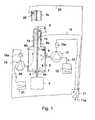
- a typical time course of flow ratesis shown in three exemplary variants, on the y-axis of the graph, the flow rate in volume per time is given, while on the x-axis, the time is plotted.
- a first graph 48shows the flow rate measured by the sensor 15 or the sensor 22, the flow rate being constant over much of the time, but from time to time, for example, every twenty seconds, or every few minutes, by a transient one Increase 49, 50 the flow rate is changed. This ensures that no stationary flow is formed in the channel 8, which may leave certain areas of the channel untouched as so-called dead water areas, so that liquid located there does not move on. A change in the flow rate generates vortices and nonstationary flow conditions, which then also detect the dead water areas and exchange the liquid there.
- a second variant 51 of the flow rate profileit is periodically varied by a constant course 52, for example in the form of a sinusoid. This results in a constantly changing flow with also constantly changing flow conditions, which guarantee a fluid exchange in all areas of the channel 8.
- the flow directionshown by the example of the flow rate reduction 55, is occasionally reversed.
- the reversal of the flowcauses a change in the flow direction of the liquid in the channel 8 and thus also the exchange of liquid in dead water areas.
- Such a reversal of the flow directioncan occur, for example, at intervals of five to ten minutes.
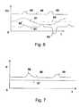
- FIG. 7Pressure readings are plotted against the time t on the y-axis, wherein a first curve 56 indicates the pressure in the region of the sensor 15 and a second curve 57 indicates the pressure in the region of the sensor 22. It can be seen that in two areas 58, 59 the pressure is temporarily raised by the first diaphragm pump 10, while the pressure in the area of the return line, detected by the sensor 22, remains constant. This requires that flows in the areas of the raised pressure 58, 59 through the bearing 33 liquid in the pump housing and thus the pressure in the channel 8 is relieved.
- a supply device in the form of a purging device for a hollow catheter for a blood pumpis realized, are used in the low wear parts and thus a stable operation with low fluid losses can be ensured for a long time.
Landscapes
- Health & Medical Sciences (AREA)
- Engineering & Computer Science (AREA)
- Heart & Thoracic Surgery (AREA)
- Mechanical Engineering (AREA)
- Cardiology (AREA)
- Life Sciences & Earth Sciences (AREA)
- Biomedical Technology (AREA)
- Hematology (AREA)
- Anesthesiology (AREA)
- Animal Behavior & Ethology (AREA)
- General Health & Medical Sciences (AREA)
- Public Health (AREA)
- Veterinary Medicine (AREA)
- General Engineering & Computer Science (AREA)
- Vascular Medicine (AREA)
- External Artificial Organs (AREA)
- Infusion, Injection, And Reservoir Apparatuses (AREA)
- Reciprocating Pumps (AREA)
Abstract
Translated fromGermanDescription
Translated fromGermanDie Erfindung liegt auf dem Gebiet der Elektrotechnik und der Mechanik und ist mit besonderem Vorteil auf dem Gebiet der Medizintechnik einsetzbar.The invention is in the field of electrical engineering and mechanics and can be used with particular advantage in the field of medical technology.
Konkret beschäftigt sich die Erfindung mit der Versorgung eines Kanals mit einer Flüssigkeit. Beispielsweise kann es notwendig sein, einen Kanal mit einer Flüssigkeit zu füllen, um die Wände des Kanals zu kühlen oder in dem Kanal angeordnete, bewegte Teile zu kühlen oder zu schmieren und/oder gasfrei zu machen. Zu diesem Zweck ist es grundsätzlich bekannt, einen derartigen Kanal, beispielsweise eine Kanüle, mit einer Kühl- und/oder Schmierflüssigkeit zu versorgen. Die Flüssigkeit kann grundsätzlich mittels einer Pumpe in den oder durch den Kanal bewegt werden.Specifically, the invention deals with the supply of a channel with a liquid. For example, it may be necessary to fill a channel with a liquid to cool the walls of the channel, or to cool or lubricate and / or degas the moving parts located in the channel. For this purpose, it is generally known to supply such a channel, for example a cannula, with a cooling and / or lubricating fluid. The liquid can in principle be moved by means of a pump into or through the channel.
Oft ist es dabei, insbesondere bei medizinischen Anwendungen, wichtig, dass einerseits durch die Flüssigkeit im Kanal keine dort entstehenden Abriebteile transportiert werden und dass andererseits die Geschwindigkeit, mit der die Flüssigkeit durch den Kanal bewegt wird, möglichst gering aber präzise gesteuert ist. Es kann zudem auch gewünscht sein, dass der Flüssigkeitsverlust aus dem Kanal minimiert wird.Often it is important, especially in medical applications, important that on the one hand by the liquid in the channel no resulting abrasion On the other hand, the speed at which the liquid is moved through the channel is as low as possible but precisely controlled. It may also be desirable to minimize fluid loss from the channel.
Aus dem Stand der Technik ist beispielsweise aus der
Aus der
Die
Vor dem Hintergrund des Standes der Technik liegt der vorliegenden Erfindung die Aufgabe zugrunde, eine Versorgungseinrichtung zur Beaufschlagung des Kanals mit einer Flüssigkeit sowie ein Verfahren zum Betrieb einer solchen Versorgungseinrichtung zu schaffen, wobei in konstruktiv einfacher Weise eine Lösung angestrebt wird, die in kontrollierter Weise die Steuerung des Durchflusses der Flüssigkeit bei geringer Durchflussrate ermöglicht.Against the background of the prior art, the present invention seeks to provide a supply device for acting on the channel with a liquid and a method for operating such a supply device, wherein in a structurally simple manner a solution is sought, in a controlled manner the Controlling the flow of the liquid at low flow rate allows.
Erfindungsgemäß wird diese Aufgabe durch eine Versorgungseinrichtung und durch ein Verfahren gemäß den unabhängigen Ansprüchen gelöst. Spezielle Ausgestaltungen sind jeweils in den Unteransprüchen beschrieben.According to the invention, this object is achieved by a supply device and by a method according to the independent claims. Specific embodiments are each described in the subclaims.
Die Erfindung bezieht sich demgemäß auf ein Verfahren zum Betrieb einer Versorgungseinrichtung, die einen Kanal mit einer Flüssigkeit beaufschlagt, mit einer Membranpumpe. Das Verfahren zeichnet sich dadurch aus, dass die Membranpumpe bezüglich des erzeugten rucks und/oder der Förderrate angesteuert wird.The invention accordingly relates to a method for operating a supply device, which applies a liquid to a channel, with a diaphragm pump. The method is characterized in that the diaphragm pump is controlled with respect to the generated ruck and / or the delivery rate.
Erfindungsgemäß wird auch eine Versorgungseinrichtung zur Beaufschlagung eines Kanals mit einer Flüssigkeit mit wenigstens einer Membranpumpe vorgeschlagen. Die Vorrichtung weist eine Steuereinrichtung auf, die die Pumpe bezüglich des erzeugten Drucks (was in einigen Ausführungsformen auch einen Unterdruck oder ein Vakuum umfassen kann) und/oder der Förderrate ansteuert.According to the invention, provision is also made of a supply device for acting on a channel with a liquid having at least one membrane pump. The apparatus includes a controller that drives the pump with respect to the pressure generated (which in some embodiments may also include a vacuum or vacuum) and / or the rate of delivery.
Die Erfindung bezieht sich auch auf ein Verfahren zum Betrieb einer Versorgungseinrichtung, die einen Kanal mit einer Flüssigkeit beaufschlagt, mit zwei an voneinander beabstandeten Stellen des Kanals angeordneten Pumpen. Dabei ist es vorgesehen, dass die Parameterwerte wenigstens eines Betriebsparameters beider Pumpen aufeinander abgestimmt gesteuert werden.The invention also relates to a method for operating a supply device, which acts on a channel with a liquid, with two arranged at spaced-apart locations of the channel pumps. It is provided that the parameter values of at least one operating parameter of both pumps are controlled in a coordinated manner.
Grundsätzlich ist es bekannt und möglich, eine Flüssigkeit mittels einer einzigen Pumpe durch einen Kanal zu bewegen. Durch die Merkmale der Erfindung, insbesondere die Verwendung mehrerer Pumpen, ist jedoch, wenn Betriebsparameter der Pumpen aufeinander abgestimmt werden, beispielsweise die Einstellung eines gemeinsamen Druckniveaus bei Einhaltung von entsprechenden Druckdifferenzen zwischen einem Einlaufbereich und einem Auslaufbereich des Kanals möglich.In principle, it is known and possible to move a liquid through a channel by means of a single pump. Due to the features of the invention, in particular the use of multiple pumps, however, when operating parameters of the pumps are coordinated, for example, the setting of a common pressure level while maintaining the corresponding pressure differences between an inlet region and a discharge region of the channel possible.
Auch die Steuerung einer Durchflussrate ist durch zwei abgestimmte Pumpen derart möglich, dass einerseits eine bestimmte Durchflussrate durch den Kanal eingestellt und andererseits Verlustraten der Flüssigkeit im Einlass- und Auslassbereich oder bei im Verlauf des Kanals vorhandenen Lecks/Öffnungen auf einen bestimmten Wert eingestellt, insbesondere begrenzt werden können.The control of a flow rate is possible by two tuned pumps such that on the one hand set a certain flow rate through the channel and on the other hand set loss rates of the liquid in the inlet and outlet or in the course of the channel leaks / openings to a certain value, in particular limited can be.
Um eine besonders gute Einstellbarkeit und damit Steuerbarkeit des Betriebs der Versorgungseinrichtung zu erreichen, bieten sich besonders Membranpumpen zur Realisierung der Versorgungseinrichtung an. Diese können bezüglich des Durchflusses, d. h. der Durchflussrate, besonders genau und reproduzierbar gesteuert werden.In order to achieve a particularly good adjustability and thus controllability of the operation of the supply device, diaphragm pumps are particularly suitable for realizing the supply device. these can with respect to the flow, ie the flow rate, are controlled very accurately and reproducibly.
Eine besonders effiziente Steuerung der Versorgungseinrichtung wird möglich, wenn in vorteilhafter Weise an zwei voneinander beabstandeten Stellen in dem Kanal der Flüssigkeitsdruck erfasst wird. Insbesondere kann jede der Stellen, an denen der Flüssigkeitsdruck erfasst wird, einer der Pumpen zugeordnet sein, und es kann mittels der Druckerfassung ein optimales Verhältnis von Saugdruck und Überdruck durch Ansteuerung der Pumpen realisiert werden. Eine solche Steuerung ist insbesondere dann wichtig, wenn der Kanal nicht geschlossen ringförmig ausgebildet ist, sondern einen Ansaugbereich aufweist, in dem dem Kanal von außen aus einem Flüssigkeitsreservoir Flüssigkeit zugeführt wird, und/oder einen Auslaufkanal aufweist, durch den Flüssigkeit aus dem Kanal in ein Auffangreservoir abgeleitet wird.A particularly efficient control of the supply device becomes possible when the liquid pressure is advantageously detected at two spaced locations in the channel. In particular, each of the points at which the fluid pressure is detected, be assigned to one of the pumps, and it can be realized by means of the pressure detection, an optimal ratio of suction pressure and pressure by controlling the pump. Such a control is particularly important if the channel is not closed ring-shaped, but has a suction, in which the channel from the outside of a liquid reservoir liquid is supplied, and / or has an outlet channel, through the liquid from the channel into a Collection reservoir is derived.
Die entsprechenden Drucksensoren können separat im Kanal aufgebaut sein, sie können jedoch auch jeweils in eine der Pumpen mit integriert sein.The corresponding pressure sensors can be constructed separately in the channel, but they can also be integrated into one of the pumps.
Als besonders vorteilhaft hat sich bei dem erfindungsgemäßen Verfahren herausgestellt, dass die abgestimmten Parameterwerte der beiden Pumpen zeitlich nach einem festen Schema veränderlich sind und insbesondere nach einer Anlaufphase zeitlich periodisch verändert werden. In der Anlaufphase kann beispielsweise wenigstens eine der Pumpen langsam in ihrer Leistung gesteigert werden. Es kann jedoch auch eine Leistungsspitze angestrebt werden, so dass die Flüssigkeit zunächst mit einer hohen Durchflussrate durch den Kanal strömt, wobei die Durchflussrate nach der Anfangsphase wieder absinkt.It has proven to be particularly advantageous in the method according to the invention that the adjusted parameter values of the two pumps are variable in time according to a fixed schedule and, in particular, are periodically changed over time after a start-up phase. In the start-up phase, for example, at least one of the pumps can be slowly increased in their performance. However, a power peak may also be sought so that the liquid first flows through the channel at a high flow rate, with the flow rate decreasing again after the initial phase.
Unabhängig von der Gestaltung der Anlaufphase kann vorgesehen sein, dass der Druck wenigstens einer der Pumpen periodisch steigend und fallend gesteuert wird oder dass entsprechend eine periodisch steigende und fallende Durchflussrate eingestellt wird. Dies ist insbesondere dann vorteilhaft, wenn innerhalb des Kanals bewegte Teile vorhanden sind, wie beispielsweise innerhalb einer Kanüle eine antreibbare Welle, die ihrerseits durch Abrieb kleine Partikel freisetzt. Üblicherweise sollen diese Partikel nicht entlang des Kanals weiterbewegt werden, jedoch soll dennoch die Flüssigkeit transportiert werden. Ein Variieren der Betriebsparameter der Pumpen erlaubt ein effizientes Spülen des Kanals mit der Flüssigkeit, wobei durch die nichtstationäre Strömung alle Teile des Kanals erreicht werden. Durch die Phasen geringeren Durchsatzes der Flüssigkeit können die Partikel in der Strömung zur Ruhe kommen, so dass der Transport der Partikel entlang des Kanals minimiert werden kann.Regardless of the design of the start-up phase can be provided that the pressure of at least one of the pumps is controlled periodically rising and falling or that, accordingly, a periodically increasing and decreasing flow rate is set. This is particularly advantageous when moving parts are present within the channel, such as within a cannula a drivable shaft, which in turn releases by abrasion small particles. Usually, these particles should not be moved along the channel, but should still transport the liquid become. Varying the operating parameters of the pumps allows for efficient flushing of the channel with the liquid, all non-stationary flow reaching all parts of the channel. Through the phases of lower throughput of the liquid, the particles in the flow can come to rest, so that the transport of the particles along the channel can be minimized.
Ein Variieren der Parameter der Pumpen kann außer der Variation der Leistung jeder einzelnen der Pumpen auch beispielsweise ein Variieren der Leistungsdifferenz oder einer durch die Pumpen erzeugten Druckdifferenz sein. Die Druckdifferenz sorgt für die Beschleunigung der Flüssigkeit und somit eine periodisch schwankende Druckdifferenz für einen entsprechend periodisch schwankenden Flüssigkeitstransport.Varying the parameters of the pumps may be, besides varying the power of each of the pumps, also varying, for example, the power difference or a pressure difference created by the pumps. The pressure difference ensures the acceleration of the liquid and thus a periodically fluctuating pressure difference for a correspondingly periodically fluctuating liquid transport.
Nachfolgend wird unter einer Flüssigkeit eine zum Spülen der Welle verwendete Flüssigkeit verstanden. In einigen Ausführungsbeispielen ist dies nicht eine von der Pumpe zu fördernde Flüssigkeit, obgleich Spuren order geringe Menge der durch die Pumpe zu fördernden Flüssigkeit auch in den Kanal gelangen kann. In anderen Ausführungsbeispielen ist die von der Pumpe zu fördernde Flüssigkeit diejenige welche zur Spülung verwendet werden kann.Hereinafter, a liquid is understood to mean a liquid used for rinsing the shaft. In some embodiments, this is not a liquid to be delivered by the pump, although traces or a small amount of the liquid to be delivered by the pump may also enter the channel. In other embodiments, the liquid to be delivered by the pump is that which can be used for flushing.
Eine weitere vorteilhafte Ausgestaltung der Erfindung sieht vor, dass die abgestimmten Parameterwerte der beiden Pumpen in einem Verhältnis zueinander stehen, das von erfassten Werten des Flüssigkeitsdrucks im Kanal in vorbestimmter Weise abhängig ist. Auf diese Weise kann der Flüssigkeitsdruck im Kanal bzw. eine Flüssigkeitsdruckdifferenz periodisch gesteuert werden.A further advantageous embodiment of the invention provides that the coordinated parameter values of the two pumps are in a relationship which depends on detected values of the fluid pressure in the channel in a predetermined manner. In this way, the fluid pressure in the channel or a fluid pressure difference can be controlled periodically.
Die Förderleistungen der Pumpen können anhand verschiedener Messgrößen bestimmt werden. In einigen Ausführungsbeispielen sind die Messgrößen bzw. Betriebsparameter zur Bestimmung der Förderleistung die Hubfrequenz der Membran, und/oder die Hubhöhe der Membran und/oder die Auslenkung der Membran. Dabei kann zur Bestimmung der Förderleistung auf eine der obigen Messgrößen oder eine Kombination mindestens zweier der obigen Messgrößen zurückgegriffen werden. Eine weitere Möglichkeit zur Bestimmung der Förderleistung ist in einigen Ausführungsbeispielen die elektrische Leistungsaufnahme der Pumpe, insbesondere unter Berücksichtigung des herrschenden Flüssigkeitsdrucks.The delivery rates of the pumps can be determined by means of various parameters. In some embodiments, the measured variables or operating parameters for determining the delivery rate are the stroke frequency of the diaphragm, and / or the lift height of the diaphragm and / or the deflection of the diaphragm. In this case, one of the above measured variables or a combination of at least two of the above measured variables can be used to determine the delivery rate. Another possibility for determining the delivery rate is in some embodiments, the electrical Power consumption of the pump, especially taking into account the prevailing fluid pressure.
Die abgestimmten Betriebsparameter beider Pumpen können somit z. B. die jeweiligen Förderleistungen sein. Es kann dann beispielsweise auch eine bestimmte Differenz der Förderleistungen zwischen den beiden Pumpen eingestellt werden. Dies kann dann beispielsweise bedingen, dass eine bestimmte Verlustrate im Verlauf des Kanals für den Flüssigkeitstransport erzeugt wird.The tuned operating parameters of both pumps can thus z. B. be the respective subsidies. It can then be set, for example, a certain difference in the flow rates between the two pumps. This may then mean, for example, that a certain loss rate is generated in the course of the liquid transport channel.
Eine weitere vorteilhafte Ausgestaltung der Erfindung sieht vor, dass die abgestimmten Betriebsparameter beider Pumpen die jeweiligen Werte des durch die Pumpen erzeugten Flüssigkeitsdrucks sind. Der Flüssigkeitsdruck lässt sich in dem Kanal besonders einfach und genau erfassen, so dass durch eine Steuerung der Pumpen beispielsweise ein bestimmter Quotient der Druckwerte oder eine bestimmte Differenz der Druckwerte einstellbar ist. Der Quotient und/oder die Differenz können auch periodisch veränderlich eingestellt werden, um eine stationäre Strömung mit Totwassergebieten zu vermeiden.A further advantageous embodiment of the invention provides that the coordinated operating parameters of both pumps are the respective values of the fluid pressure generated by the pumps. The fluid pressure can be particularly easily and accurately detected in the channel, so that, for example, a certain quotient of the pressure values or a specific difference of the pressure values can be set by controlling the pumps. The quotient and / or the difference can also be adjusted periodically variable in order to avoid stationary flow with dead water areas.
Eine weitere vorteilhafte Ausgestaltung der Erfindung sieht vor, dass die abgestimmten Betriebsparameter beider Pumpen die jeweiligen elektrischen Leistungsaufnahmen der Pumpen sind. Dazu kann jeder Pumpe ein elektrischer Sensor zur Erfassung der Leistungsaufnahme der Pumpe, insbesondere zur Erfassung der Stromaufnahme, zugeordnet sein.A further advantageous embodiment of the invention provides that the matched operating parameters of both pumps are the respective electrical power consumption of the pump. For this purpose, each pump can be assigned an electrical sensor for detecting the power consumption of the pump, in particular for detecting the current consumption.
Es kann zudem vorteilhaft vorgesehen sein, dass die abgestimmten Betriebsparameter beider Pumpen die jeweiligen Durchflussraten der Pumpen sind. Die Durchflussraten können beispielsweise durch Durchflussmesssensoren separat erfasst werden oder auch durch die Aufnahme der Betriebsparameter der Pumpen, beispielsweise die Leistungsaufnahme und den herrschenden Fluiddruck.It can also be advantageously provided that the matched operating parameters of both pumps are the respective flow rates of the pump. The flow rates can be detected separately, for example by flow measuring sensors or by recording the operating parameters of the pump, for example, the power consumption and the prevailing fluid pressure.
Zudem kann vorteilhaft vorgesehen sein, dass zwischen den beiden Pumpen eine feste Druckdifferenz und/oder eine feste Differenz der Durchflussrate eingestellt wird. Dabei kann insbesondere vorgesehen sein, dass die Differenz der Durchflussraten beider Pumpen kleiner ist als 100 Milliliter pro Tag, insbesondere kleiner ist als 10 Milliliter pro Tag oder kleiner als 1 Milliliter pro Tag.In addition, it can be advantageously provided that a fixed pressure difference and / or a fixed difference in the flow rate is set between the two pumps. In particular, it may be provided that the difference in the flow rates of both pumps is less than 100 milliliters per day, especially less than 10 milliliters per day or less than 1 milliliter per day.
Entsprechende Verlustraten werden an den Öffnungen des Kanals eingestellt. Beispielsweise kann der Kanal einen Transportkanal und einen Rückflusskanal aufweisen, wobei der Transportkanal beispielsweise an einer am Ende einer Kanüle angeordneten Blutpumpe endet und der Rückflusskanal an derselben Stelle beginnt. Ein Teil der Flüssigkeit, der die Differenz der Durchflussraten ausmacht, kann dann beispielsweise durch die Blutpumpe abströmen, diese spülen und im implantierten Zustand in den Körper eines Patienten abgeleitet werden. In einer Weiterbildung der Erfindung wird in einem solchen Anwendungsfall als Flüssigkeit eine biokompatible, gesundheitsverträgliche Flüssigkeit gewählt, wie beispielsweise eine Kochsalzlösung.Corresponding loss rates are set at the openings of the channel. For example, the channel may have a transport channel and a return channel, wherein the transport channel ends, for example, at a blood pump arranged at the end of a cannula and the return channel starts at the same point. A portion of the fluid, which is the difference in flow rates, may then flow out, for example, through the blood pump, flushing it, and, when implanted, draining it into the body of a patient. In one development of the invention, in such an application, a biocompatible, health-compatible liquid is selected as the liquid, such as a saline solution.
Bei einer vorteilhaften Betriebsform des Verfahrens kann außerdem vorgesehen sein, dass die Bewegungsrichtung der Flüssigkeit umgekehrt wird. Eine solche Umkehrung der Bewegungsrichtung der Flüssigkeit kann periodisch vorgesehen sein oder auch nur zu bestimmten Anlässen. Üblicherweise wird bei der Verwendung zu einer Spülung eines Pumpenkatheters eine Transportrichtung der Flüssigkeit von einem proximalen Ende des Katheters zu einem distalen Ende des Katheters und durch einen Rückflusskanal zurück in einen Auffangbehälter gewählt.In an advantageous mode of operation of the method can also be provided that the direction of movement of the liquid is reversed. Such a reversal of the direction of movement of the liquid may be provided periodically or only on certain occasions. Typically, when used to flush a pump catheter, a direction of transport of fluid from a proximal end of the catheter to a distal end of the catheter and through a return flow channel back into a collection container is selected.
Die Erfindung bezieht sich außer auf ein Verfahren zum Betrieb einer Versorgungseinrichtung auch auf die Gestaltung einer Versorgungseinrichtung zur Beaufschlagung eines Kanals mit einer Flüssigkeit, mit wenigstens zwei Pumpen, insbesondere Membranpumpen, die an voneinander beabstandeten Stellen des Kanals angeordnet sind, sowie mit einer Steuereinrichtung, die die Pumpen bezüglich des erzeugten Drucks und/oder der Förderrate einzeln ansteuert.The invention relates not only to a method for operating a supply device to the design of a supply device for acting on a channel with a liquid, with at least two pumps, in particular diaphragm pumps, which are arranged at spaced-apart locations of the channel, and with a control device, the individually controls the pumps with regard to the pressure generated and / or the delivery rate.
Die Steuereinrichtung muss derart gestaltet sein, dass sie eine abgestimmte Ansteuerung der einzelnen Pumpen erlaubt. Sie kann einer der Pumpen zugeordnet oder auch als separate zentrale Steuereinheit ausgebildet sein. Die Steuereinrichtung kann auch zur Regelung von Betriebsparametern der Pumpen dienen und ist dann mit Sensoren zur Erfassung von Messwerten verbunden.The control device must be designed so that it allows a coordinated control of the individual pumps. It can be assigned to one of the pumps or can also be designed as a separate central control unit. The control device can also be used to control operating parameters of the Pumps are used and is then connected to sensors for the acquisition of measured values.
Beispielsweise kann vorgesehen sein, dass jeder Pumpe ein Flüssigkeitsdrucksensor zugeordnet ist. Durch die Steuereinrichtung kann dann ein bestimmtes Druckverhältnis zwischen Saugdruck und Überdruck oder ein bestimmter Quotient der durch die beiden Pumpen erzeugten Drücke oder eine bestimmte Druckdifferenz ausgesteuert werden.For example, it can be provided that each pump is assigned a fluid pressure sensor. The control device can then be used to control a specific pressure ratio between suction pressure and overpressure or a specific quotient of the pressures generated by the two pumps or a specific pressure difference.
Da die Messgrößen zur Bestimmung der Förderleistung der Pumpen druckabhängig sein können, können die Pumpen beispielsweise als Drucksensoren betrieben werden, wenn ihre Leistungsaufnahme erfasst und der Steuereinrichtung zugeführt wird. Jedoch kann die Leistungsaufnahme auch ein Indikator für die mittels der jeweiligen Pumpe erzielte Durchflussrate sein und als solche erfasst werden. Hierzu ist üblicherweise zudem der herrschende Flüssigkeitsdruck zu berücksichtigen, so dass bei einem solchen Betrieb der gleichzeitige Betrieb von Druckmesssensoren vorteilhaft ist.Since the measured variables for determining the delivery rate of the pumps can be pressure-dependent, the pumps can be operated, for example, as pressure sensors if their power consumption is detected and supplied to the control device. However, the power consumption can also be an indicator of the flow rate achieved by the respective pump and be detected as such. For this purpose, the prevailing fluid pressure is usually also taken into account, so that in such an operation, the simultaneous operation of pressure measuring sensors is advantageous.
Es können jedoch Durchflussratensensoren vorgesehen sein, von denen jeweils einer jeder der Pumpen zugeordnet ist. Es kann dann durch die Steuereinrichtung ein bestimmtes Verhältnis der Durchflussraten im Bereich der ersten und der zweiten Pumpe oder eine vorbestimmte Differenz eingestellt werden. Eine solche Differenz der Durchflussraten kann beispielsweise auch periodisch veränderlich angesteuert werden.However, flow rate sensors may be provided, one of which is associated with each of the pumps. It can then be set by the controller, a certain ratio of the flow rates in the range of the first and the second pump or a predetermined difference. Such a difference in the flow rates can be controlled, for example, periodically variable.
Im Folgenden wird die Erfindung anhand von Ausführungsbeispielen in Figuren einer Zeichnung gezeigt und anschließend beschrieben. Dabei zeigt
- Fig. 1
- einen Hohlkatheter mit einer antreibbaren Welle sowie einer erfindungsgemäßen Versorgungseinrichtung,
- Fig. 2
- das Ende eines Hohlkatheters in einem Längsschnitt mit einer distal befestigten Rotationspumpe für den Betrieb in einem Blutgefäß,
- Fig. 3
- einen Querschnitt durch einen Hohlkatheter,
- Fig. 4
- einen Querschnitt durch einen weiteren Hohlkatheter,
- Fig. 5
- einen Verfahrensablauf für ein Verfahren zum Betrieb einer Versorgungseinrichtung,
- Fig. 6
- ein Diagramm, das den zeitlichen Verlauf von Durchflussraten in drei verschiedenen Varianten wiedergibt, sowie
- Fig. 7
- ein Diagramm, das einen zeitlichen Verlauf des Flüssigkeitsdrucks wiedergibt.
- Fig. 1
- a hollow catheter having a drivable shaft and a supply device according to the invention,
- Fig. 2
- the end of a hollow catheter in a longitudinal section with a distally mounted rotary pump for operation in a blood vessel,
- Fig. 3
- a cross section through a hollow catheter,
- Fig. 4
- a cross section through another hollow catheter,
- Fig. 5
- a method sequence for a method for operating a supply device,
- Fig. 6
- a diagram showing the time course of flow rates in three different variants, as well as
- Fig. 7
- a diagram showing a time course of the fluid pressure.
Innerhalb des Hohlkatheters 1 verläuft eine drehbar antreibbare Welle 2. Diese dient beispielsweise zum Antrieb einer Blutpumpe und ist an ihrem proximalen Ende 2a mit einem Antriebsmotor 3 verbunden. Die Welle 2 kann im Bereich einer Durchführung 4 in ein Koppelgehäuse 5 eingeführt sein, wobei die Durchführung 4 derart gestaltet ist, dass durch eine Dichtung das Passieren eines Mediums entlang der Welle in das Koppelgehäuse 5 hinein oder aus dem Koppelgehäuse 5 heraus verhindert wird.Within the
Es ist jedoch auch die Lösung denkbar, dass die rotierende Antriebsbewegung mittels einer Magnetkupplung durch eine geschlossene Wand des Koppelgehäuses 5 übertragen wird, indem ein erstes Magnetelement 6 innerhalb des Koppelgehäuses magnetisch mit einem zweiten Magnetelement 7 gekoppelt ist, das außerhalb des Koppelgehäuses 5 auf einem mit dem Motor 3 verbundenen Wellenstumpf befestigt ist. Die Welle 2 weist dann zwischen dem Motor 3 und ihrem weiteren Verlauf im Koppelgehäuse 5 eine Unterbrechung auf, und die entsprechende Wand des Koppelgehäuses 5 ist durchgehend und ohne eine Öffnung ausgebildet. Die Magnetelemente 6, 7 sind in
Die Antriebswelle 2 ist beispielsweise aus Litzen, insbesondere in verdrehter oder verseilter Form, hergestellt oder als Schraubenfeder ausgebildet oder in einer Kombination beider Varianten durch eine Seele mit einer diese umgebenden Schraubenfeder gebildet, um einerseits hohe Umdrehungszahlen im Bereich von einigen tausend Umdrehungen pro Minute übertragen zu können und dabei andererseits biegsam zu sein.The
Um eine solche Welle einerseits im Betrieb zu kühlen und andererseits die Reibung durch Schmierung zu vermindern, ist üblicherweise innerhalb des in dem Hohlkatheter 1 gebildeten Kanals 8 eine Kühl- und Schmierflüssigkeit vorgesehen, die vorteilhaft biokompatibel ist. Die Flüssigkeit wird dem Koppelgehäuse 5 über einen Zuflusskanal 9 zugeführt und entlang des Kanals 8 transportiert. Hierzu ist der Zuflusskanal 9 mit einer ersten Pumpe, die in dem Ausführungsbeispiel als Membranpumpe 10 ausgebildet ist, verbunden. Membranpumpen haben in diesem Zusammenhang die Eigenschaft, sehr zuverlässig und reproduzierbar ansteuerbar zu sein, um erzeugte Drücke und Durchflussraten exakt steuern zu können. Als besonders vorteilhaft erweist sich in diesem Zusammenhang die Verwendung von magnetisch angesteuerten Membranpumpen. Deshalb ist in
Die Membranpumpe 10 saugt aus einem Zulaufreservoir 12 Flüssigkeit an, wie durch den Pfeil 13 dargestellt ist, und transportiert diese mit einer einstellbaren Durchflussrate und einem einstellbaren Druck über den Zuflusskanal 9 in das Koppelgehäuse 5 hinein. In dem Koppelgehäuses 5 verteilt sich die Flüssigkeit und bewegt sich insbesondere in Richtung des Pfeils 14 entlang des Kanals 8 in Richtung des distalen Endes 1b des Hohlkatheters. Die Bewegung entlang des Kanals 8 kann beispielsweise durch die Drehung der Welle 2 unterstützt werden, wenn diese eine wenigstens teilweise helixförmige Außenkontur aufweist und in einer geeigneten Rotationsrichtung rotiert. Obgleich die Drehung der Welle 2 die Bewegung der Flüssigkeit entlang des Kanals 8 unterstützen kann, ist es in einigen Ausführungsbeispielen möglich, den Beitrag der Drehung der Welle zur Förderleistung zu bestimmen, um so die Förderleistung der Pumpe(n) anzupassen. D.h. die aufgrund der Drehung der Welle auftretende Förderleistung wird durch eine Anpassung der Förderleistung der Pumpen kompensiert. Die Bestimmung der Förderleistung aufgrund der Drehung der Welle kann dann auch als Störgröße interpretiert werden, welche durch die Anpassung der Förderleistung der Pumpen ausgeglichen wird, um eine vorbestimme Förderleistung durch den Kanal zu gewährleisten. Die Förderleistung der Welle 8 kann unter anderem von der Drehzahl der Welle, eventuellem Verschleiß an der Welle, der Biegung des Katheters oder ähnlichem abhängen. Obgleich diese Größen bestimmbar sind, ist eine Kompensation der resultierenden Förderleistung der Welle durch die Pumpe oftmals einfacher.The
Üblicherweise können mittels der Ansteuerung der Membranpumpe 10 Durchflussraten im Bereich von Mikrolitern oder Millilitern pro Stunde eingestellt werden.Usually 10 flow rates in the range of microliters or milliliters per hour can be adjusted by the control of the diaphragm pump.
Um entsprechende Durchflussraten und/oder Drücke geeignet steuern oder regeln zu können, ist wenigstens ein geeigneter Sensor 15 in dem Kanal 8 vorgesehen, der mittels einer Kommunikationsleitung 16 mit der Steuereinrichtung 11 verbunden ist. Der Sensor 15 kann beispielsweise als Drucksensor, als Durchflussratensensor oder als kombinierter Sensor zur Erfassung des Drucks und der Durchflussrate ausgebildet sein.In order to be able to control or regulate appropriate flow rates and / or pressures, at least one
In dem gezeigten Ausführungsbeispiel ist der Sensor 15 der ersten Membranpumpe 10 zugeordnet und erfasst den durch diese erste Pumpe erzeugten Druck und/oder die entsprechende Durchflussrate.In the embodiment shown, the
Der Kanal 8 ist gemäß dem Ausführungsbeispiel der
Der Rückkanal 8b kann beispielsweise durch eine Trennwand 17, die in
Der Rückkanal 8b ist gemäß
Die Steuereinrichtung 11 ist zudem mit einem zweiten Sensor 22 verbunden, der, ebenso wie der erste Sensor 15, als Durchlaufsensor und/oder als Drucksensor ausgebildet sein kann und der dem Rückkanal 8b und damit der zweiten Membranpumpe 19 zugeordnet ist. Beispielsweise kann durch den zweiten Sensor 22 die Durchflussrate des Rückkanals 8b oder der Saugdruck der zweiten Membranpumpe 19 erfasst werden. Die durch den zweiten Sensor 22 erfassten Parameter werden über eine zweite Kommunikationsleitung 23 der Steuereinrichtung 11 zugeführt.The
Die Steuereinrichtung 11 ist ihrerseits mit einem elektrischen Versorgungsanschluss 11a verbunden, der die Steuereinrichtung mit einer niedrigen Gleichspannung (Kleinspannung) versorgt. Die Steuereinrichtung 11 erzeugt Impulse, die den Magneteinrichtungen 10a, 19a zum Antrieb der ersten und zweiten Membranpumpe 10, 19 zugeleitet werden. Mittels der Frequenz und des Hubs der durch die Steuereinrichtung 11 erzeugten Impulse können die Durchflussraten und/oder Drücke gesteuert werden, die durch die erste und zweite Membranpumpe 10, 19 erzeugt werden.The
Die Welle 2 ist am Ende des Hohlkatheters 1 in einem Durchführungslager 33 gelagert, das einerseits hohe Rotationszahlen zulassen, andererseits möglichst dicht sein soll, um einen Flüssigkeitsaustausch entlang der Welle 2 zu verhindern oder zu begrenzen. Es soll insbesondere verhindert werden, dass Blut aus dem Inneren des Gehäuses 27 der Blutpumpe 24 in den Hohlkatheter 1, d. h. in den Kanal 8, gelangt.The
In
Um das Einströmen von Blut in den Kanal 8 zu verhindern, kann ein Überdruck der Flüssigkeit im Inneren des Hohlkatheters 1, d. h. im Kanal 8, eingestellt werden, der dazu führt, dass mit einer sehr geringen Durchflussrate Flüssigkeit aus dem Kanal 8 in das Gehäuse der Blutpumpe 24 einströmt, wie durch die Pfeile 36, 37 angedeutet ist. Beispielsweise kann hier eine Ausflussrate von wenigen Mikrolitern oder Millilitern pro Tag eingestellt werden, die eine Differenz zwischen der Zulaufrate im ersten Kanalbereich 8a und der Rücklaufrate im Rückkanal 8b darstellt. Diese Differenz ist als Differenz der Förderraten zwischen der ersten Pumpe 10 und der zweiten Pumpe 19 einstellbar und messbar.In order to prevent the inflow of blood into the
In
In einem dritten Schritt 40 wird entschieden, ob die Leistungen der Pumpen manuell eingestellt werden sollen. Werden die Pumpen manuell eingestellt, so verläuft der weitere Prozess über den Weg 40a, und in einem Schritt 46 werden die Drücke und/oder Durchflussraten der beiden Pumpen eingestellt. Üblicherweise wird diese Variante wohl gewählt, wenn die Spülrate, d. h. die Durchflussrate durch den Kanal 8, klein und konstant sein soll.In a
Soll keine manuelle Ansteuerung gewählt werden, so verläuft der weitere Weg über den Pfeil 40b, und es wird in einem vierten Schritt 41 die automatische Ansteuerung der Pumpen begonnen. Hierzu wird zunächst im Schritt 41 der Druck an den zwei Drucksensoren 15, 22 erfasst, hieraus eine Druckdifferenz berechnet und aus dieser in einem fünften Schritt 42 die Ansteuerung der Pumpen 10, 19 durch entsprechende Pulse der Steuereinrichtung 11 berechnet. Dabei kann die angestrebte Druckdifferenz auch zeitlich veränderlich, beispielsweise periodisch variierend sein.If no manual control is selected, the further path is via the
In einem sechsten Schritt 43 wird die erzeugte Druckdifferenz mit der Solldruckdifferenz verglichen. Entspricht die Istdruckdifferenz der Solldruckdifferenz, so wird in einem siebten Schritt 44 beispielsweise die Druckdifferenz oder eine hieraus berechnete Spülrate angezeigt und in einem achten Schritt 45 das Verfahren beendet. Die Beendigung des Verfahrens bedeutet, dass sich die Versorgungseinrichtung in einem stabilen Betriebszustand befindet und die Pumpen 10, 19 entsprechend angesteuert werden und arbeiten. Wird in dem sechsten Schritt 43 festgestellt, dass die Istdruckdifferenz nicht der Solldruckdifferenz entspricht, so springt das Verfahren über den Weg 43a zu dem vierten Schritt 41 zurück, an dem die Druckdifferenz gemessen und hieraus in einem Regelschritt die neue Ansteuerung der Pumpen ermittelt wird.In a
Anstelle der Druckmessungen und entsprechender Druckregelung des Differenzdrucks kann auch die Durchflussrate gemessen und eine entsprechende Durchflussratendifferenz als Regelgröße eingestellt werden.Instead of the pressure measurements and appropriate pressure control of the differential pressure, the flow rate can be measured and a corresponding flow rate difference can be set as a controlled variable.
In
Es ist weiterhin Aufgabe einer entsprechenden Steuerung der Durchflussrate, Partikel, die sich in der Flüssigkeit befinden und die beispielsweise durch Abrieb der rotierenden Welle 2 entstehen, möglichst nicht weiterzubewegen, so dass diese nicht durch das in
Wenn man in demselben Diagramm die durch die beiden Sensoren 15, 22 erfassten Durchflussraten aufträgt, so kann sich beispielsweise besonders in den Bereichen 49, 50 eine angehobene Durchflussrate mit einer besonders auffälligen Differenz der Durchflussraten einstellen, was anzeigt, dass in diesen Bereichen 49, 50 stoßweise in sehr kleinen Mengen etwas von der Flüssigkeit aus dem Kanal 8 in das Innere des Pumpengehäuses der Blutpumpe austritt und somit möglicherweise dort abgelagerte Mengen des Blutes aus dem Lager 33 wegspült.If, in the same diagram, the flow rates recorded by the two
In einer zweiten Variante 51 des Durchflussratenverlaufs wird dieser um einen konstanten Verlauf 52 herum periodisch, beispielsweise in Form einer Sinuskurve, variiert. So ergibt sich ein sich ständig ändernder Durchfluss mit sich ebenfalls ständig ändernden Strömungsverhältnissen, die einen Flüssigkeitsaustausch in allen Bereichen des Kanals 8 garantieren.In a
In der dritten Variante, die in der Kurve 53 dargestellt ist, wird außer vorübergehenden periodischen Anhebungen 54 der Durchflussrate gelegentlich auch die Durchflussrichtung, gezeigt am Beispiel der Absenkung 55 der Durchflussrate, umgekehrt. Die Umkehrung des Durchflusses bedingt eine Änderung der Flussrichtung der Flüssigkeit im Kanal 8 und damit ebenfalls den Austausch von Flüssigkeit in Totwassergebieten. Eine solche Umkehrung der Flussrichtung kann beispielsweise jeweils im Abstand von fünf bis zehn Minuten geschehen.In the third variant, which is shown in the
In
Durch die oben beschriebene Erfindung wird eine Versorgungseinrichtung in Form einer Spüleinrichtung für einen Hohlkatheter für eine Blutpumpe realisiert, bei der wenig Verschleißteile eingesetzt werden und somit über lange Zeit ein stabiler Betrieb mit geringen Flüssigkeitsverlusten gewährleistet werden kann.By the invention described above, a supply device in the form of a purging device for a hollow catheter for a blood pump is realized, are used in the low wear parts and thus a stable operation with low fluid losses can be ensured for a long time.
Claims (17)
Translated fromGermanPriority Applications (25)
| Application Number | Priority Date | Filing Date | Title |
|---|---|---|---|
| EP20130188579EP2860399A1 (en) | 2013-10-14 | 2013-10-14 | Method for operating a supply device that supplies a channel with a liquid, and supply device |
| DK14781610.2TDK3060805T3 (en) | 2013-10-14 | 2014-10-09 | Method of operating a supply device affecting a channel with a fluid, as well as a supply device, hollow catheter and catheter pump |
| EP14781610.2AEP3060805B1 (en) | 2013-10-14 | 2014-10-09 | Method for operating a supply device that supplies a channel with liquid, supply device, hollow catheter and catheter pump |
| HK16111993.6AHK1223670B (en) | 2013-10-14 | 2014-10-09 | Method for operating a supply device which supplies a liquid to channel, and supply device, hollow catheter, and catheter pump |
| US15/029,092US10195323B2 (en) | 2013-10-14 | 2014-10-09 | Method for operating a supply device which supplies a liquid to a channel, and supply device, hollow catheter, and catheter pump |
| PCT/EP2014/071706WO2015055515A1 (en) | 2013-10-14 | 2014-10-09 | Method for operating a supply device which supplies a liquid to a channel, and supply device, hollow catheter, and catheter pump |
| DK19195945.1TDK3594500T3 (en) | 2013-10-14 | 2014-10-09 | Method of operating a supply device affecting a channel with a fluid, as well as supply device and catheter pump |
| JP2016523279AJP6758181B2 (en) | 2013-10-14 | 2014-10-09 | Catheter pump |
| EP19195945.1AEP3594500B8 (en) | 2013-10-14 | 2014-10-09 | Method for operating a supply device that supplies a channel with liquid, supply device and catheter pump |
| KR1020167012259AKR102311071B1 (en) | 2013-10-14 | 2014-10-09 | Method for operating a supply device that supplies a channel with a liquid, and supply device, hollow catheter and catheter pump |
| EP22162535.3AEP4033100A1 (en) | 2013-10-14 | 2014-10-09 | Method for operating a supply device that supplies a channel with liquid, supply device, hollow catheter and catheter pump |
| KR1020237007535AKR102829629B1 (en) | 2013-10-14 | 2014-10-09 | Method for operating a supply device that supplies a channel with a liquid, and supply device, hollow catheter and catheter pump |
| KR1020257021964AKR20250105502A (en) | 2013-10-14 | 2014-10-09 | Method for operating a supply device that supplies a channel with a liquid, and supply device, hollow catheter and catheter pump |
| KR1020217031033AKR20210121302A (en) | 2013-10-14 | 2014-10-09 | Method for operating a supply device that supplies a channel with a liquid, and supply device, hollow catheter and catheter pump |
| ES14781610TES2768339T3 (en) | 2013-10-14 | 2014-10-09 | Procedure for operating a delivery device that pumps fluid into a canal, as well as delivery device, hollow catheter, and catheter pump |
| CN201810088071.XACN108457844B (en) | 2013-10-14 | 2014-10-09 | Method for operating a supply device for supplying liquid to a channel, and supply device, hollow conduit and conduit pump |
| CA2925422ACA2925422A1 (en) | 2013-10-14 | 2014-10-09 | Method for operating a supply device that supplies a channel with a liquid, and supply device, hollow catheter and catheter pump |
| ES19195945TES2916710T3 (en) | 2013-10-14 | 2014-10-09 | Method for the operation of a delivery device that propels a liquid in a channel, as well as a delivery device and a catheter pump |
| CN201480055960.6ACN105917118B (en) | 2013-10-14 | 2014-10-09 | Method for operating a supply device for supplying liquid to a channel, and supply device, hollow catheter and catheter pump |
| HK18112222.5AHK1252877B (en) | 2013-10-14 | 2018-09-21 | Method for operating a supply device which supplies a liquid to a channel, and supply device, hollow catheter, and catheter pump |
| US16/228,005US10780205B2 (en) | 2013-10-14 | 2018-12-20 | Method for operating a supply device which supplies a liquid to a channel, and supply device, hollow catheter, and catheter pump |
| JP2020092840AJP7050854B2 (en) | 2013-10-14 | 2020-05-28 | Catheter pump |
| US16/989,111US20210023284A1 (en) | 2013-10-14 | 2020-08-10 | Method for operating a supply device which supplies a liquid to a channel, and supply device, hollow catheter, and catheter pump |
| JP2022053014AJP7372378B2 (en) | 2013-10-14 | 2022-03-29 | catheter pump |
| JP2023180085AJP7736756B2 (en) | 2013-10-14 | 2023-10-19 | catheter pump |
Applications Claiming Priority (1)
| Application Number | Priority Date | Filing Date | Title |
|---|---|---|---|
| EP20130188579EP2860399A1 (en) | 2013-10-14 | 2013-10-14 | Method for operating a supply device that supplies a channel with a liquid, and supply device |
Publications (1)
| Publication Number | Publication Date |
|---|---|
| EP2860399A1true EP2860399A1 (en) | 2015-04-15 |
Family
ID=49488465
Family Applications (4)
| Application Number | Title | Priority Date | Filing Date |
|---|---|---|---|
| EP20130188579WithdrawnEP2860399A1 (en) | 2013-10-14 | 2013-10-14 | Method for operating a supply device that supplies a channel with a liquid, and supply device |
| EP14781610.2AActiveEP3060805B1 (en) | 2013-10-14 | 2014-10-09 | Method for operating a supply device that supplies a channel with liquid, supply device, hollow catheter and catheter pump |
| EP22162535.3APendingEP4033100A1 (en) | 2013-10-14 | 2014-10-09 | Method for operating a supply device that supplies a channel with liquid, supply device, hollow catheter and catheter pump |
| EP19195945.1AActiveEP3594500B8 (en) | 2013-10-14 | 2014-10-09 | Method for operating a supply device that supplies a channel with liquid, supply device and catheter pump |
Family Applications After (3)
| Application Number | Title | Priority Date | Filing Date |
|---|---|---|---|
| EP14781610.2AActiveEP3060805B1 (en) | 2013-10-14 | 2014-10-09 | Method for operating a supply device that supplies a channel with liquid, supply device, hollow catheter and catheter pump |
| EP22162535.3APendingEP4033100A1 (en) | 2013-10-14 | 2014-10-09 | Method for operating a supply device that supplies a channel with liquid, supply device, hollow catheter and catheter pump |
| EP19195945.1AActiveEP3594500B8 (en) | 2013-10-14 | 2014-10-09 | Method for operating a supply device that supplies a channel with liquid, supply device and catheter pump |
Country Status (9)
| Country | Link |
|---|---|
| US (3) | US10195323B2 (en) |
| EP (4) | EP2860399A1 (en) |
| JP (4) | JP6758181B2 (en) |
| KR (4) | KR102829629B1 (en) |
| CN (2) | CN108457844B (en) |
| CA (1) | CA2925422A1 (en) |
| DK (2) | DK3594500T3 (en) |
| ES (2) | ES2768339T3 (en) |
| WO (1) | WO2015055515A1 (en) |
Cited By (2)
| Publication number | Priority date | Publication date | Assignee | Title |
|---|---|---|---|---|
| CN107882668A (en)* | 2017-12-28 | 2018-04-06 | 潍柴动力股份有限公司 | A kind of fuel filter seat |
| EP3536955A1 (en)* | 2018-03-08 | 2019-09-11 | Berlin Heart GmbH | Drive device for a membrane fluid pump and operation method |
Families Citing this family (62)
| Publication number | Priority date | Publication date | Assignee | Title |
|---|---|---|---|---|
| US7393181B2 (en) | 2004-09-17 | 2008-07-01 | The Penn State Research Foundation | Expandable impeller pump |
| CN102380135A (en) | 2006-03-23 | 2012-03-21 | 宾州研究基金会 | Heart assist device with expandable impeller pump |
| WO2012094641A2 (en) | 2011-01-06 | 2012-07-12 | Thoratec Corporation | Percutaneous heart pump |
| EP4218887A1 (en) | 2012-05-14 | 2023-08-02 | Tc1 Llc | Mechanical circulatory support device for stabilizing a patient after cardiogenic shock |
| US9872947B2 (en) | 2012-05-14 | 2018-01-23 | Tc1 Llc | Sheath system for catheter pump |
| US9446179B2 (en) | 2012-05-14 | 2016-09-20 | Thoratec Corporation | Distal bearing support |
| US8721517B2 (en) | 2012-05-14 | 2014-05-13 | Thoratec Corporation | Impeller for catheter pump |
| EP4186557A1 (en) | 2012-07-03 | 2023-05-31 | Tc1 Llc | Motor assembly for catheter pump |
| US9421311B2 (en) | 2012-07-03 | 2016-08-23 | Thoratec Corporation | Motor assembly for catheter pump |
| US9358329B2 (en) | 2012-07-03 | 2016-06-07 | Thoratec Corporation | Catheter pump |
| US11033728B2 (en) | 2013-03-13 | 2021-06-15 | Tc1 Llc | Fluid handling system |
| WO2014164136A1 (en) | 2013-03-13 | 2014-10-09 | Thoratec Corporation | Fluid handling system |
| US11077294B2 (en) | 2013-03-13 | 2021-08-03 | Tc1 Llc | Sheath assembly for catheter pump |
| EP4190376A1 (en) | 2013-03-15 | 2023-06-07 | Tc1 Llc | Catheter pump assembly including a stator |
| US9308302B2 (en) | 2013-03-15 | 2016-04-12 | Thoratec Corporation | Catheter pump assembly including a stator |
| EP2860399A1 (en) | 2013-10-14 | 2015-04-15 | ECP Entwicklungsgesellschaft mbH | Method for operating a supply device that supplies a channel with a liquid, and supply device |
| EP3131597B1 (en) | 2014-04-15 | 2020-12-02 | Tc1 Llc | Catheter pump introducer systems |
| WO2015160943A1 (en) | 2014-04-15 | 2015-10-22 | Thoratec Corporation | Sensors for catheter pumps |
| EP3131599B1 (en) | 2014-04-15 | 2019-02-20 | Tc1 Llc | Catheter pump with access ports |
| US10583232B2 (en) | 2014-04-15 | 2020-03-10 | Tc1 Llc | Catheter pump with off-set motor position |
| EP3583973A1 (en) | 2014-08-18 | 2019-12-25 | Tc1 Llc | Guide features for percutaneous catheter pump |
| US9675738B2 (en)* | 2015-01-22 | 2017-06-13 | Tc1 Llc | Attachment mechanisms for motor of catheter pump |
| US9770543B2 (en) | 2015-01-22 | 2017-09-26 | Tc1 Llc | Reduced rotational mass motor assembly for catheter pump |
| WO2016118781A2 (en) | 2015-01-22 | 2016-07-28 | Thoratec Corporation | Motor assembly with heat exchanger for catheter pump |
| EP3808401A1 (en) | 2016-07-21 | 2021-04-21 | Tc1 Llc | Gas-filled chamber for catheter pump motor assembly |
| US11160970B2 (en) | 2016-07-21 | 2021-11-02 | Tc1 Llc | Fluid seals for catheter pump motor assembly |
| CA3066361A1 (en) | 2017-06-07 | 2018-12-13 | Shifamed Holdings, Llc | Intravascular fluid movement devices, systems, and methods of use |
| WO2019094963A1 (en) | 2017-11-13 | 2019-05-16 | Shifamed Holdings, Llc | Intravascular fluid movement devices, systems, and methods of use |
| DE102018201030B4 (en) | 2018-01-24 | 2025-10-16 | Kardion Gmbh | Magnetic dome element with magnetic bearing function |
| CN112004563B (en) | 2018-02-01 | 2024-08-06 | 施菲姆德控股有限责任公司 | Intravascular blood pump and methods of use and manufacture |
| DE102018207575A1 (en) | 2018-05-16 | 2019-11-21 | Kardion Gmbh | Magnetic face turning coupling for the transmission of torques |
| DE102018207611A1 (en) | 2018-05-16 | 2019-11-21 | Kardion Gmbh | Rotor bearing system |
| DE102018208550A1 (en) | 2018-05-30 | 2019-12-05 | Kardion Gmbh | A lead device for directing blood flow to a cardiac assist system, cardiac assist system, and method of making a lead device |
| DE102018208541A1 (en) | 2018-05-30 | 2019-12-05 | Kardion Gmbh | Axial pump for a cardiac assist system and method of making an axial pump for a cardiac assist system |
| DE102018208538A1 (en) | 2018-05-30 | 2019-12-05 | Kardion Gmbh | Intravascular blood pump and process for the production of electrical conductors |
| DE102018208539A1 (en) | 2018-05-30 | 2019-12-05 | Kardion Gmbh | A motor housing module for sealing an engine compartment of a motor of a cardiac assist system and cardiac assistance system and method for mounting a cardiac assist system |
| DE102018208933A1 (en) | 2018-06-06 | 2019-12-12 | Kardion Gmbh | A method of determining a flow rate of fluid flowing through an implanted vascular support system |
| DE102018208862A1 (en) | 2018-06-06 | 2019-12-12 | Kardion Gmbh | Implantable vascular support system |
| DE102018208929A1 (en) | 2018-06-06 | 2019-12-12 | Kardion Gmbh | A method of determining a flow rate of fluid flowing through an implanted vascular support system |
| DE102018208936A1 (en) | 2018-06-06 | 2019-12-12 | Kardion Gmbh | Determining device and method for determining a viscosity of a fluid |
| DE102018208913A1 (en) | 2018-06-06 | 2019-12-12 | Kardion Gmbh | A method of operating an implanted ventricular assist device |
| DE102018208945A1 (en) | 2018-06-06 | 2019-12-12 | Kardion Gmbh | An analysis device and method for analyzing a viscosity of a fluid |
| DE102018208899A1 (en) | 2018-06-06 | 2019-12-12 | Kardion Gmbh | A method for determining the speed of sound in a fluid in the region of an implanted vascular support system |
| DE102018208879A1 (en) | 2018-06-06 | 2020-01-30 | Kardion Gmbh | Method for determining a total fluid volume flow in the area of an implanted, vascular support system |
| DE102018210058A1 (en) | 2018-06-21 | 2019-12-24 | Kardion Gmbh | Stator blade device for guiding the flow of a fluid flowing out of an outlet opening of a heart support system, heart support system with stator blade device, method for operating a stator blade device and manufacturing method |
| DE102018210076A1 (en) | 2018-06-21 | 2019-12-24 | Kardion Gmbh | Method and device for detecting a state of wear of a cardiac support system, method and device for operating a cardiac support system and cardiac support system |
| DE102018211327A1 (en) | 2018-07-10 | 2020-01-16 | Kardion Gmbh | Impeller for an implantable vascular support system |
| DE102018212153A1 (en) | 2018-07-20 | 2020-01-23 | Kardion Gmbh | Inlet line for a pump unit of a cardiac support system, cardiac support system and method for producing an inlet line for a pump unit of a cardiac support system |
| US12161857B2 (en) | 2018-07-31 | 2024-12-10 | Shifamed Holdings, Llc | Intravascular blood pumps and methods of use |
| CN112654389A (en) | 2018-08-07 | 2021-04-13 | 开迪恩有限公司 | Bearing device for a cardiac support system and method for flushing an intermediate space in a bearing device for a cardiac support system |
| WO2020073047A1 (en) | 2018-10-05 | 2020-04-09 | Shifamed Holdings, Llc | Intravascular blood pumps and methods of use |
| WO2021011473A1 (en) | 2019-07-12 | 2021-01-21 | Shifamed Holdings, Llc | Intravascular blood pumps and methods of manufacture and use |
| US11654275B2 (en) | 2019-07-22 | 2023-05-23 | Shifamed Holdings, Llc | Intravascular blood pumps with struts and methods of use and manufacture |
| US12121713B2 (en) | 2019-09-25 | 2024-10-22 | Shifamed Holdings, Llc | Catheter blood pumps and collapsible blood conduits |
| WO2021062265A1 (en) | 2019-09-25 | 2021-04-01 | Shifamed Holdings, Llc | Intravascular blood pump systems and methods of use and control thereof |
| EP4501393A3 (en) | 2019-09-25 | 2025-04-09 | Shifamed Holdings, LLC | Catheter blood pumps and collapsible pump housings |
| CN110917420B (en)* | 2019-11-27 | 2022-06-21 | 丰凯利医疗器械(上海)有限公司 | Flexible shaft structure for isolating and discharging wear particles through pouring |
| EP4072650A4 (en) | 2019-12-11 | 2024-01-10 | Shifamed Holdings, LLC | Descending aorta and vena cava blood pumps |
| DE102020102474A1 (en) | 2020-01-31 | 2021-08-05 | Kardion Gmbh | Pump for conveying a fluid and method for manufacturing a pump |
| US20240001101A1 (en)* | 2020-12-04 | 2024-01-04 | Shifamed Holdings, Llc | Catheter blood pumps and external fluid control consoles |
| EP4302797A4 (en)* | 2021-03-23 | 2024-08-07 | TERUMO Kabushiki Kaisha | MEDICAL INSTRUMENT |
| CN112891732B (en)* | 2021-05-07 | 2021-08-03 | 丰凯医疗器械(上海)有限公司 | A perfusate delivery device and control method thereof |
Citations (10)
| Publication number | Priority date | Publication date | Assignee | Title |
|---|---|---|---|---|
| DD202805A1 (en) | 1981-12-28 | 1983-10-05 | Otto Grotewohl Boehlen Boehlen | PUMP FOR SMALLEST VOLUMINA |
| DE69409587T2 (en) | 1993-06-22 | 1998-11-26 | Siemens-Elema Ab, Solna | Method of rinsing a catheter and catheter |
| DE102007040328A1 (en)* | 2007-08-24 | 2009-02-26 | Henkel Ag & Co. Kgaa | Toilet freshener with directed release of active ingredient |
| DE102007059239A1 (en)* | 2007-12-07 | 2009-06-10 | Thomas Magnete Gmbh | Diaphragm, and reciprocating diaphragm pump |
| DE202009014152U1 (en)* | 2009-10-19 | 2011-03-03 | Dürr Optronik GmbH & Co. KG | Unwinding device for a material web |
| EP2388028A1 (en)* | 2010-05-20 | 2011-11-23 | Berlin Heart GmbH | Method for operating a pump system |
| EP2389961A1 (en)* | 2010-05-31 | 2011-11-30 | ORTHOS Orthopädietechnik GmbH | Medical device for improving the wound healing process |
| DE202005021999U1 (en) | 2004-08-06 | 2012-02-17 | Zoll Circulation, Inc. | Heating / cooling system for a heat exchange permanent catheter |
| DE102011106111A1 (en)* | 2011-06-09 | 2012-12-13 | Fresenius Medical Care Deutschland Gmbh | Method and device for determining at least one absolute pressure-dependent operating parameter of an extracorporeal blood treatment device, device for extracorporeal blood treatment |
| DE102011053935A1 (en)* | 2011-09-26 | 2013-03-28 | Fresenius Medical Care Deutschland Gmbh | Method, device and system for blood treatment of a patient |
Family Cites Families (20)
| Publication number | Priority date | Publication date | Assignee | Title |
|---|---|---|---|---|
| DE202805C (en) | ||||
| US5116350B1 (en)* | 1987-03-17 | 1997-06-17 | Cordis Corp | Catheter system having distal tip for opening obstructions |
| US4895557A (en) | 1987-12-07 | 1990-01-23 | Nimbus Medical, Inc. | Drive mechanism for powering intravascular blood pumps |
| EP0516726A4 (en)* | 1990-02-20 | 1993-04-28 | The Regents Of The University Of California | Apparatus, catheter and method for chemical contact dissolution of gallstones |
| EP0954244A1 (en)* | 1994-07-01 | 1999-11-10 | SciMed Life Systems, Inc. | Intravascular device utilizing fluid to extract occlusive material |
| US5843022A (en)* | 1995-10-25 | 1998-12-01 | Scimied Life Systems, Inc. | Intravascular device utilizing fluid to extract occlusive material |
| AU2284400A (en) | 1998-12-18 | 2000-07-12 | Berlin Heart Ag | Pulsatile pump |
| AU7354400A (en)* | 1999-09-03 | 2001-04-10 | A-Med Systems, Inc. | Guidable intravascular blood pump and related methods |
| DE10040403A1 (en) | 2000-08-18 | 2002-02-28 | Impella Cardiotech Ag | Intracardiac blood pump |
| US7311703B2 (en) | 2003-07-18 | 2007-12-25 | Vivant Medical, Inc. | Devices and methods for cooling microwave antennas |
| JP2005169094A (en)* | 2003-11-21 | 2005-06-30 | Terumo Corp | Laser induced liquid jet generating apparatus |
| JP2009522037A (en)* | 2006-01-09 | 2009-06-11 | バイオスパイラル リミティッド | Tissue thermal treatment system and method |
| JP5250866B2 (en)* | 2008-06-11 | 2013-07-31 | 株式会社サンメディカル技術研究所 | Artificial heart control device and artificial heart system |
| US7985986B2 (en) | 2008-07-31 | 2011-07-26 | Cree, Inc. | Normally-off semiconductor devices |
| CN201293204Y (en) | 2009-03-09 | 2009-08-19 | 韩红卫 | Full automatic centralization supplier for liquid auxiliary raw material |
| JP5468414B2 (en)* | 2010-02-22 | 2014-04-09 | 国立大学法人 岡山大学 | Brain cooling device and brain cooling device suitable for the same |
| EP2363157A1 (en)* | 2010-03-05 | 2011-09-07 | ECP Entwicklungsgesellschaft mbH | Device for exerting mechanical force on a medium, in particular fluid pump |
| WO2012094641A2 (en)* | 2011-01-06 | 2012-07-12 | Thoratec Corporation | Percutaneous heart pump |
| WO2012094535A2 (en)* | 2011-01-06 | 2012-07-12 | Thoratec Corporation | Percutaneous heart pump |
| EP2860399A1 (en) | 2013-10-14 | 2015-04-15 | ECP Entwicklungsgesellschaft mbH | Method for operating a supply device that supplies a channel with a liquid, and supply device |
- 2013
- 2013-10-14EPEP20130188579patent/EP2860399A1/ennot_activeWithdrawn
- 2014
- 2014-10-09KRKR1020237007535Apatent/KR102829629B1/enactiveActive
- 2014-10-09KRKR1020217031033Apatent/KR20210121302A/ennot_activeCeased
- 2014-10-09CNCN201810088071.XApatent/CN108457844B/enactiveActive
- 2014-10-09KRKR1020257021964Apatent/KR20250105502A/enactivePending
- 2014-10-09KRKR1020167012259Apatent/KR102311071B1/enactiveActive
- 2014-10-09CNCN201480055960.6Apatent/CN105917118B/enactiveActive
- 2014-10-09ESES14781610Tpatent/ES2768339T3/enactiveActive
- 2014-10-09USUS15/029,092patent/US10195323B2/enactiveActive
- 2014-10-09EPEP14781610.2Apatent/EP3060805B1/enactiveActive
- 2014-10-09EPEP22162535.3Apatent/EP4033100A1/enactivePending
- 2014-10-09ESES19195945Tpatent/ES2916710T3/enactiveActive
- 2014-10-09DKDK19195945.1Tpatent/DK3594500T3/enactive
- 2014-10-09DKDK14781610.2Tpatent/DK3060805T3/enactive
- 2014-10-09EPEP19195945.1Apatent/EP3594500B8/enactiveActive
- 2014-10-09WOPCT/EP2014/071706patent/WO2015055515A1/enactiveApplication Filing
- 2014-10-09CACA2925422Apatent/CA2925422A1/enactivePending
- 2014-10-09JPJP2016523279Apatent/JP6758181B2/enactiveActive
- 2018
- 2018-12-20USUS16/228,005patent/US10780205B2/enactiveActive
- 2020
- 2020-05-28JPJP2020092840Apatent/JP7050854B2/enactiveActive
- 2020-08-10USUS16/989,111patent/US20210023284A1/enactivePending
- 2022
- 2022-03-29JPJP2022053014Apatent/JP7372378B2/enactiveActive
- 2023
- 2023-10-19JPJP2023180085Apatent/JP7736756B2/enactiveActive
Patent Citations (10)
| Publication number | Priority date | Publication date | Assignee | Title |
|---|---|---|---|---|
| DD202805A1 (en) | 1981-12-28 | 1983-10-05 | Otto Grotewohl Boehlen Boehlen | PUMP FOR SMALLEST VOLUMINA |
| DE69409587T2 (en) | 1993-06-22 | 1998-11-26 | Siemens-Elema Ab, Solna | Method of rinsing a catheter and catheter |
| DE202005021999U1 (en) | 2004-08-06 | 2012-02-17 | Zoll Circulation, Inc. | Heating / cooling system for a heat exchange permanent catheter |
| DE102007040328A1 (en)* | 2007-08-24 | 2009-02-26 | Henkel Ag & Co. Kgaa | Toilet freshener with directed release of active ingredient |
| DE102007059239A1 (en)* | 2007-12-07 | 2009-06-10 | Thomas Magnete Gmbh | Diaphragm, and reciprocating diaphragm pump |
| DE202009014152U1 (en)* | 2009-10-19 | 2011-03-03 | Dürr Optronik GmbH & Co. KG | Unwinding device for a material web |
| EP2388028A1 (en)* | 2010-05-20 | 2011-11-23 | Berlin Heart GmbH | Method for operating a pump system |
| EP2389961A1 (en)* | 2010-05-31 | 2011-11-30 | ORTHOS Orthopädietechnik GmbH | Medical device for improving the wound healing process |
| DE102011106111A1 (en)* | 2011-06-09 | 2012-12-13 | Fresenius Medical Care Deutschland Gmbh | Method and device for determining at least one absolute pressure-dependent operating parameter of an extracorporeal blood treatment device, device for extracorporeal blood treatment |
| DE102011053935A1 (en)* | 2011-09-26 | 2013-03-28 | Fresenius Medical Care Deutschland Gmbh | Method, device and system for blood treatment of a patient |
Cited By (8)
| Publication number | Priority date | Publication date | Assignee | Title |
|---|---|---|---|---|
| CN107882668A (en)* | 2017-12-28 | 2018-04-06 | 潍柴动力股份有限公司 | A kind of fuel filter seat |
| CN107882668B (en)* | 2017-12-28 | 2023-12-19 | 潍柴动力股份有限公司 | Fuel filter seat |
| EP3536955A1 (en)* | 2018-03-08 | 2019-09-11 | Berlin Heart GmbH | Drive device for a membrane fluid pump and operation method |
| WO2019170553A1 (en)* | 2018-03-08 | 2019-09-12 | Berlin Heart Gmbh | Drive device for a diaphragm fluid pump and operating method |
| US10441695B2 (en) | 2018-03-08 | 2019-10-15 | Berlin Heart Gmbh | Drive device for a membrane fluid pump and operating method |
| CN111819362A (en)* | 2018-03-08 | 2020-10-23 | 柏林心脏有限公司 | Drive device for diaphragm fluid pump and method of operation |
| US11141579B2 (en) | 2018-03-08 | 2021-10-12 | Berlin Heart Gmbh | Drive device for a membrane fluid pump and operating method |
| CN111819362B (en)* | 2018-03-08 | 2022-09-27 | 柏林心脏有限公司 | Drive device for diaphragm fluid pump and method of operation |
Also Published As
Similar Documents
| Publication | Publication Date | Title |
|---|---|---|
| EP3060805B1 (en) | Method for operating a supply device that supplies a channel with liquid, supply device, hollow catheter and catheter pump | |
| DE69101106T2 (en) | Method and device for regulating the flow of a heart prosthesis with periodic flow. | |
| DE69230837T2 (en) | Fluid treatment system | |
| EP1382291B1 (en) | Device for irrigation of a body cavity | |
| EP2835141B1 (en) | Control of a blood pump | |
| WO2017102164A1 (en) | Blood pump for supporting the heart, and method for operating the blood pump | |
| DE69200773T2 (en) | Device and method for leveling a liquid in a chamber of an extracorporeal blood circuit. | |
| DE68906744T2 (en) | An in-line infiltration detection device and method. | |
| EP3263148B1 (en) | Method for determining the operating parameters of a blood pump | |
| EP1286240B1 (en) | Method of determining a pump-characteristic | |
| EP0925080A1 (en) | Intracardiac blood pump | |
| EP3088016A1 (en) | Pump and method for operating a pump for liquids | |
| EP0279931A2 (en) | Membrane pump | |
| EP3108809A1 (en) | Method and device for measuring pressure on a patient's heart | |
| EP3164168A2 (en) | Method and heart support system for determining an outlet pressure | |
| DE202008016450U1 (en) | Breast pump for pumping milk from a breast | |
| EP0967475B1 (en) | Method for the determination of the viscosity of a liquid | |
| WO2019234153A1 (en) | Implantable vascular support system | |
| WO2016166114A1 (en) | Pump and method for operating a pump for liquids | |
| DE3726453A1 (en) | Medical device | |
| DE102014221865B3 (en) | Method for calibrating a fluid pump arrangement | |
| DE102022107119A1 (en) | Control device for a peristaltic pump, peristaltic pump, injection device and method for controlling a peristaltic pump | |
| EP2053249A2 (en) | Assembly with vacuum pump and method | |
| DE10322404B4 (en) | Dosing pump and method for its control | |
| DE102024108564A1 (en) | Dosing device and dosing method |
Legal Events
| Date | Code | Title | Description |
|---|---|---|---|
| PUAI | Public reference made under article 153(3) epc to a published international application that has entered the european phase | Free format text:ORIGINAL CODE: 0009012 | |
| 17P | Request for examination filed | Effective date:20131014 | |
| AK | Designated contracting states | Kind code of ref document:A1 Designated state(s):AL AT BE BG CH CY CZ DE DK EE ES FI FR GB GR HR HU IE IS IT LI LT LU LV MC MK MT NL NO PL PT RO RS SE SI SK SM TR | |
| AX | Request for extension of the european patent | Extension state:BA ME | |
| STAA | Information on the status of an ep patent application or granted ep patent | Free format text:STATUS: THE APPLICATION IS DEEMED TO BE WITHDRAWN | |
| 18D | Application deemed to be withdrawn | Effective date:20151016 |