EP2859860A1 - Multifunctional instrument - Google Patents
Multifunctional instrumentDownload PDFInfo
- Publication number
- EP2859860A1 EP2859860A1EP20130187651EP13187651AEP2859860A1EP 2859860 A1EP2859860 A1EP 2859860A1EP 20130187651EP20130187651EP 20130187651EP 13187651 AEP13187651 AEP 13187651AEP 2859860 A1EP2859860 A1EP 2859860A1
- Authority
- EP
- European Patent Office
- Prior art keywords
- fluid
- fluid chamber
- multifunctional instrument
- instrument
- active electrode
- Prior art date
- Legal status (The legal status is an assumption and is not a legal conclusion. Google has not performed a legal analysis and makes no representation as to the accuracy of the status listed.)
- Granted
Links
Images


Classifications
- A—HUMAN NECESSITIES
- A61—MEDICAL OR VETERINARY SCIENCE; HYGIENE
- A61B—DIAGNOSIS; SURGERY; IDENTIFICATION
- A61B17/00—Surgical instruments, devices or methods
- A61B17/32—Surgical cutting instruments
- A61B17/3203—Fluid jet cutting instruments
- A—HUMAN NECESSITIES
- A61—MEDICAL OR VETERINARY SCIENCE; HYGIENE
- A61B—DIAGNOSIS; SURGERY; IDENTIFICATION
- A61B1/00—Instruments for performing medical examinations of the interior of cavities or tubes of the body by visual or photographical inspection, e.g. endoscopes; Illuminating arrangements therefor
- A61B1/012—Instruments for performing medical examinations of the interior of cavities or tubes of the body by visual or photographical inspection, e.g. endoscopes; Illuminating arrangements therefor characterised by internal passages or accessories therefor
- A61B1/015—Control of fluid supply or evacuation
- A—HUMAN NECESSITIES
- A61—MEDICAL OR VETERINARY SCIENCE; HYGIENE
- A61B—DIAGNOSIS; SURGERY; IDENTIFICATION
- A61B17/00—Surgical instruments, devices or methods
- A61B17/32—Surgical cutting instruments
- A—HUMAN NECESSITIES
- A61—MEDICAL OR VETERINARY SCIENCE; HYGIENE
- A61B—DIAGNOSIS; SURGERY; IDENTIFICATION
- A61B18/00—Surgical instruments, devices or methods for transferring non-mechanical forms of energy to or from the body
- A61B18/04—Surgical instruments, devices or methods for transferring non-mechanical forms of energy to or from the body by heating
- A61B18/12—Surgical instruments, devices or methods for transferring non-mechanical forms of energy to or from the body by heating by passing a current through the tissue to be heated, e.g. high-frequency current
- A61B18/14—Probes or electrodes therefor
- A61B18/1402—Probes for open surgery
- A—HUMAN NECESSITIES
- A61—MEDICAL OR VETERINARY SCIENCE; HYGIENE
- A61M—DEVICES FOR INTRODUCING MEDIA INTO, OR ONTO, THE BODY; DEVICES FOR TRANSDUCING BODY MEDIA OR FOR TAKING MEDIA FROM THE BODY; DEVICES FOR PRODUCING OR ENDING SLEEP OR STUPOR
- A61M5/00—Devices for bringing media into the body in a subcutaneous, intra-vascular or intramuscular way; Accessories therefor, e.g. filling or cleaning devices, arm-rests
- A61M5/14—Infusion devices, e.g. infusing by gravity; Blood infusion; Accessories therefor
- A—HUMAN NECESSITIES
- A61—MEDICAL OR VETERINARY SCIENCE; HYGIENE
- A61B—DIAGNOSIS; SURGERY; IDENTIFICATION
- A61B17/00—Surgical instruments, devices or methods
- A61B2017/00017—Electrical control of surgical instruments
- A61B2017/00225—Systems for controlling multiple different instruments, e.g. microsurgical systems
- A—HUMAN NECESSITIES
- A61—MEDICAL OR VETERINARY SCIENCE; HYGIENE
- A61B—DIAGNOSIS; SURGERY; IDENTIFICATION
- A61B18/00—Surgical instruments, devices or methods for transferring non-mechanical forms of energy to or from the body
- A61B2018/00571—Surgical instruments, devices or methods for transferring non-mechanical forms of energy to or from the body for achieving a particular surgical effect
- A61B2018/00589—Coagulation
- A—HUMAN NECESSITIES
- A61—MEDICAL OR VETERINARY SCIENCE; HYGIENE
- A61B—DIAGNOSIS; SURGERY; IDENTIFICATION
- A61B18/00—Surgical instruments, devices or methods for transferring non-mechanical forms of energy to or from the body
- A61B2018/00571—Surgical instruments, devices or methods for transferring non-mechanical forms of energy to or from the body for achieving a particular surgical effect
- A61B2018/00601—Cutting
- A—HUMAN NECESSITIES
- A61—MEDICAL OR VETERINARY SCIENCE; HYGIENE
- A61B—DIAGNOSIS; SURGERY; IDENTIFICATION
- A61B18/00—Surgical instruments, devices or methods for transferring non-mechanical forms of energy to or from the body
- A61B2018/00994—Surgical instruments, devices or methods for transferring non-mechanical forms of energy to or from the body combining two or more different kinds of non-mechanical energy or combining one or more non-mechanical energies with ultrasound
- A—HUMAN NECESSITIES
- A61—MEDICAL OR VETERINARY SCIENCE; HYGIENE
- A61B—DIAGNOSIS; SURGERY; IDENTIFICATION
- A61B18/00—Surgical instruments, devices or methods for transferring non-mechanical forms of energy to or from the body
- A61B18/04—Surgical instruments, devices or methods for transferring non-mechanical forms of energy to or from the body by heating
- A61B2018/044—Surgical instruments, devices or methods for transferring non-mechanical forms of energy to or from the body by heating the surgical action being effected by a circulating hot fluid
- A61B2018/046—Surgical instruments, devices or methods for transferring non-mechanical forms of energy to or from the body by heating the surgical action being effected by a circulating hot fluid in liquid form
- A—HUMAN NECESSITIES
- A61—MEDICAL OR VETERINARY SCIENCE; HYGIENE
- A61B—DIAGNOSIS; SURGERY; IDENTIFICATION
- A61B18/00—Surgical instruments, devices or methods for transferring non-mechanical forms of energy to or from the body
- A61B18/04—Surgical instruments, devices or methods for transferring non-mechanical forms of energy to or from the body by heating
- A61B2018/044—Surgical instruments, devices or methods for transferring non-mechanical forms of energy to or from the body by heating the surgical action being effected by a circulating hot fluid
- A61B2018/048—Surgical instruments, devices or methods for transferring non-mechanical forms of energy to or from the body by heating the surgical action being effected by a circulating hot fluid in gaseous form
- A—HUMAN NECESSITIES
- A61—MEDICAL OR VETERINARY SCIENCE; HYGIENE
- A61B—DIAGNOSIS; SURGERY; IDENTIFICATION
- A61B18/00—Surgical instruments, devices or methods for transferring non-mechanical forms of energy to or from the body
- A61B18/04—Surgical instruments, devices or methods for transferring non-mechanical forms of energy to or from the body by heating
- A61B18/12—Surgical instruments, devices or methods for transferring non-mechanical forms of energy to or from the body by heating by passing a current through the tissue to be heated, e.g. high-frequency current
- A61B18/14—Probes or electrodes therefor
- A61B2018/1405—Electrodes having a specific shape
- A61B2018/1425—Needle
Definitions
- the inventionrelates to a multifunction instrument for RF surgical treatment of tissue according to claim 1.
- Instruments for RF surgical treatment of tissueare generally known.
- the problem hereis often undesirable side effects that can result from the flow of current through the tissue of the patient, especially in the respective surgical area. These undesirable side effects occur especially in large-scale and superficial procedures such as argon plasma coagulation (APC) or spray coagulation.
- APCargon plasma coagulation
- spray coagulationDue to the high voltages used there, which are up to 4500 V, interference from electromagnetic fields can be caused by electronic peripheral devices in the operating environment. These can u. a. have negative effects on patient monitoring, for example on the ECG.
- Minimally invasive proceduresalso require the use of an endoscopic or laparoscopic camera whose image can be adversely affected by the high voltage and electromagnetic fields generated by it. In order to avoid interference, it is therefore necessary to use highly insulating materials to shield the corresponding devices.
- Another disadvantage of conventional RF surgical proceduresis the carbonation effects of the treated tissue as well as neuromuscular Stimulations induced by the HF current.
- Another disadvantage of conventional RF surgical instrumentsis the need to change instruments for different RF surgical procedures, such as cutting, injecting or coagulating tissue, which hinders the course of surgery.
- a thermal tissue treatment by RF surgical coagulationshould be carried out as gently as possible. This also includes a reduction in the coagulation depth while increasing the areal extent of the coagulation area.
- the multi-function instrumentcomprises the following elements: at least one fluid chamber for receiving a fluid; a temperature control device connected to the at least one fluid chamber for heating, heating or evaporating a fluid present in the at least one fluid chamber; a temperature controller for controlling the temperature of the fluid present in the at least one fluid chamber, and at least one fluid outlet opening disposed at a distal end of the multifunctional instrument and communicating with the at least one fluid chamber.
- an essential point of the inventionis therefore that the present multi-functional instrument can not only use a fluid for cutting and injecting tissue with a targeted water jet, but also that the fluid can be heated, in particular heated and even vaporized.
- the fluidcan be heated, in particular heated and even vaporized.
- a superficial, thermal effect with low penetration during coagulationcan be generated and the treated tissue can be devitalized over a large area. Carbonisation effects become thereby minimized.
- the coagulation depthis lower and the areal extent of the coagulation effect is higher due to the steam generated.
- the fluid in the fluid chambercan be heated, heated or evaporated directly at the site of the operation and thus flexibly adapted to the particular application as needed.
- the tempering devicecomprises at least two tempering electrodes arranged at a distance from one another which form a wall of the fluid chamber at least in regions.
- the paired Temper istselektrodenhave a radial distance from each other, which is defined in particular by at least one preferably annularly shaped spacer.
- the at least two Temper michselektrodenare preferably arranged in the axial direction at the same height, but in the radial direction at a distance from the insulation.
- the spacerscan be dispensed with if the tempering electrodes are fixedly mounted on an inner surface of a particularly cylindrical and flexible casing and are preferably in the form of a coating, film or other thin material layer.
- the temperature control electrodescan thus also be flexibly attached to a casing so that the flexibility of the casing, in particular for the use of the multifunctional instrument as a laparoscopic or endoscopic instrument, is not hindered. Furthermore, it can be provided that a plurality of Temper istselektrodenforme are provided in the axial direction of the sheath of the multifunction instrument and in particular are mounted in a segment-like manner on the inner surface of the sheath. In this way, it is avoided that a continuous electrode surface in the axial direction of the casing does not break during a bending of the casing and thus a current flow is interrupted.
- the temperature controllercan set the electrical power supplied to the temperature control device, in particular the temperature control electrodes, as a function of a predetermined fluid flow rate. In this way it is possible to determine the temperature of the fluid without additional sensors by the flow rate known from the HF surgical device and the supplied electrical power.
- the at least one fluid outlet openingis arranged in a waveguide-shaped active electrode, which projects in particular beyond a distal end of a casing.
- the hollow-conductor-shaped active electrodeis preferably cylindrical.
- the proximal end of the active electrodepreferably projects into the fluid chamber. In this way, non-evaporated fluid drops collect in the distal region between the active electrode and the wall of the fluid chamber, so that the liquid can not escape through the hollow-conductor-shaped active electrode.
- the diameter of the at least one fluid chamberis preferably larger than the diameter of the active electrode.
- the active electrodecan be used advantageously both as a mechanical cutting instrument and as a coagulation electrode.
- the two types of electrodespreferably have separate terminals for the supply of a high-frequency current from one or more HF generators. It is particularly advantageous if the distal end of the active electrode is designed as a cutting tool for the mechanical cutting of tissue. In particular, it is provided here that the distal end of the active electrode for mechanical cutting has a cutting edge or the same cutting instrument.
- a multi-functional instrumentwhich has not only a single, but two or more fluid outlet openings, which are arranged at the distal end of the multi-function instrument.
- the one or more fluid outlet openingsmay be in communication with a single fluid chamber or with a plurality of separate fluid chambers.
- the at least one and each further fluid outlet openingmay be formed as a nozzle-like axial passage opening in an instrument attachment connected to the sheath at the distal end of the instrument. In this way, not only a directional water jet but simultaneously or alternatively also steam can be delivered by the multifunctional instrument.
- the positioning of the passage openingscan take place symmetrically or asymmetrically and in particular centrically or eccentrically.
- itcan be provided to arrange the active electrode with the at least one fluid outlet opening centrally in the instrument attachment, while one or more further fluid outlet openings are arranged eccentrically around the active electrode fluid outlet opening.
- a concentric arrangement around a central fluid outlet opening in the region of the active electrodecan be provided.
- a suitable valve devicemay be provided.
- the valve devicemay be formed, for example, as a passive ball or as an active piezo valve.
- the valve deviceis preferably arranged at a proximal end of the fluid outlet opening, in particular at a proximal end of the instrument attachment.
- each fluid chamberis associated with a separate fluid outlet opening.
- a fluid chamber for the supply of a focused water jet for water jet cuttingmay be provided, while a further fluid chamber for supplying liquid for generating steam in the course of a Koagulationsvorgangs is used.
- the surgical systemhas an RF generator for generating a high-frequency treatment current and for generating a Temper istsstroms, and also includes a multifunctional instrument according to the invention.
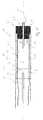
- FIG. 1shows a schematic sectional view of a multifunctional instrument 1 according to the invention.
- the multifunctional instrument 1comprises a fluid chamber 3 for receiving a fluid suitable for the treatment of the human body, for example water or a physiological saline solution (0.9% NaCl).
- the fluidpasses through a fluid inlet 5 into the fluid chamber 3.
- the multifunctional instrument 1further comprises a sheath 7, which surrounds the fluid chamber 3.
- a tempering device 9in the form of paired Temper istselektroden 11, 11 'is provided which form the wall of the fluid chamber 3 at least partially.
- the fluid chamber 3is bounded by a wall 13, which is connected to the fluid inlet 5 and has a corresponding recess for receiving the same.
- the fluid inlet 5is preferably arranged centrally in the wall 13, so that the fluid chamber 3 is in fluid communication with the fluid inlet 5.
- the fluid inlet 5is in turn connected at its proximal end to a corresponding fluid pump or the like fluid delivery device of a surgical system.
- the Temperiansselektroden 11 and 11 'are connected via electrical connections 15 and 15' with an RF generator 17 which conducts a high-frequency current to the Temper michselektroden 11 and 11 ', and which is in particular part of an electrosurgical unit.
- theyare arranged at a distance a to each other.
- spacers 19are provided, which are embedded in particular in the electrodes 11 and 11' and prevent them from abutting one another.
- the spacersmay be, for example, annular elements formed of a ceramic or plastic material.
- a total of three spacers 19are provided, which extend in sections in the axial direction A segment-like between the Temper GmbHselektroden 11 and 11 '.
- the Temperiansselektroden 11 and 11 'are formed of a conductive material and preferably extend over the entire length L of the fluid chamber 3.
- an instrument attachment 23is provided, in particular the form-fitting in the distal end of the cylindrical casing 7 of the Multi-functional instrument 1 engages and this closes tightly.
- a corresponding step 25 of the instrument attachmentis on the one hand on the inner surface 27 of the shell and on the other hand on the end face S of the shell 7 at.
- an active electrode 29 in the fluid chamber 3which is formed as a tubular member. It extends beyond an end face S of the instrument attachment 23 and protrudes with its proximal end 33 into the fluid chamber 3.
- the active electrode 29is preferably mounted slidably in the instrument attachment 23 in the axial direction A, so that a distal end 31b of the active electrode 29 can protrude more or less far beyond the end face S of the instrument attachment 23.
- the active electrode 29further has a fluid passage opening 31 designed as an axial passage opening, which is in fluid communication with the fluid chamber 3 at its proximal end 31a and whose distal end 31b is designed as a nozzle for generating a jet of water or for delivering a vapor to an operating area.
- the (monopolar) active electrode 29is connected to the RF generator 17 via an electrical connection 35.
- the electrical connection 35is arranged separately from the electrical connections 15 and 15 'of the temperature control electrodes 11 and 11'. It should be noted at this point that via a further terminal 37 of the RF generator can be connected to a neutral electrode, not shown, which serves to return an initiated by the monopolar active electrode 29 in a patient stream.
- the multifunctional instrument 1comprises a further fluid outlet opening 39, which is arranged in an axial direction in the instrument attachment 23 eccentrically to the active electrode 29.
- the fluid outlet opening 39has a valve device 41, which is shown here by way of example as a passive ball valve, which opens or closes the fluid outlet opening 39 as a function of a pressure prevailing in the fluid chamber 3.
- the valve device 41may be designed such that the valve opens at a low pressure prevailing in the fluid chamber 3, in particular if the fluid present there has been vaporized, and closes at higher pressures, ie when the fluid is in liquid form.
- the ratio of the diameters of the fluid outlet openings 31 and 39is preferably such that the central fluid outlet opening 31 formed in the active electrode 29 preferably has a smaller diameter than the eccentric second fluid outlet opening 39.
- the first fluid outlet opening 31has a diameter of approximately 50 Has -500 microns
- the second fluid outlet opening 39may have a correspondingly larger diameter.
- the FIG. 2shows a sectional view of the multifunction instrument 1 along the section line A (s. FIG. 1 ).
- the sectionruns through the jacket 7, the first temperature-control electrode 11, the spacer 19, the fluid chamber 3 and through the second opposing temperature-control electrode 11 '.
- the sheath 7 of the multi-function instrument 1is formed substantially cylindrical.
- itis formed of a flexible material, so that the multifunctional instrument can be used as a laparoscopic or endoscopic instrument for minimally invasive surgery.
- the two Temperiansselektroden 11 and 11 'are identical and substantially mirror image with respect.
- a center plane M of the multi-function instrumentarranged. In other words, they are arranged in the axial direction A at the same height, while they are arranged offset in the radial direction by 180 ° to each other.
- Both Temper stressesselektroden 11 and 11 'are substantially C-shaped or half-shell-shaped, so that a circular spacer 19 on both inner surfaces of the Temper michselektroden 11, 11' can engage positively. Of the Spacer 19 ensures compliance with an isolation distance between the Temper GmbHselektroden 11, 11 '.
- FIG. 3shows a sectional view along in FIG. 1 The section thus runs through the sheath 7, the two Temper istselektroden 11 and 11 'and through the fluid chamber 3.
- Die FIG. 3 5shows that the fluid chamber 3 comprises both an inner region 32 surrounded concentrically by the temperature control electrodes 11, 11 'and outer regions 34 which are each formed between mutually spaced circumferential end sections of the temperature control electrodes 11, 11'.
- the eccentric second fluid outlet opening 39can communicate with the fluid chamber 3 via a radially outer region 34.
- FIG. 4shows a sectional view along a sectional plane C through the multi-function instrument 1 (s. FIG. 1 ).
- the sectional plane Cextends through the sheath 7, the two Temper istselektroden 11 and 11 'through a spacer 19 and through the tubular active electrode 29.
- Die FIG. 4makes it clear that in the region of the active electrode 29 of the spacer 19 has a larger diameter than the other spacers 19.
- the fluid outlet opening 31 in the active electrode 29has otherwise a diameter which substantially coincides with the inner diameter of the inner region 32nd , which forms an inner cylindrical fluid chamber channel, and which forms with the aid of the spacers 19 between the two temperature control electrodes 11 and 11 '(see also FIG. 1 ).
- FIG. 5shows yet another embodiment of the invention, in which the multi-functional instrument 1 has substantially planar Temper michselektroden 11 and 11 ', which may be formed, for example, stainless steel.
- the Temper michselektroden 11 and 11 'are applied in the form of a thin layer of material on the inner surface 27 of the casing 7.
- a segmental division of the Temper michselektroden 11 and 11 'is provided to prevent breakage of the electrode in the event of bending of the flexible sheath 7.
- a spacer 19for example, a ceramic material or the like insulating material to be provided between the electrodes. It is understood that the spacer 19 must be designed so that it does not block a flowing from the fluid inlet 5 into the fluid chamber 3 and flowing to the fluid outlet opening 31 fluid. Also in the example shown, a fluid outlet opening 31 may be formed as a central through hole in an active electrode 29, which projects beyond an end face S of an instrument attachment 23.
- the diameter of the active electrode 29is significantly smaller than the diameter of the fluid chamber 3 in a radial direction r of the multifunction instrument 1.
- a fluid collection chamber 30is formed, which can prevent unevaporated fluid from entering the fluid outlet opening 31.
- the present inventionprovides an advantageous multi-functional instrument, which on the one hand can generate a focused water jet, and at the same time is able to heat the fluid used in this case by an HF current. This heating can take place until the fluid evaporates, with the HF current used for this not flowing via the patient, but only via the connections 15, 15 'within the instrument. It is thus a separate from the patient circuit circuit that operates the temperature control. It should be noted at this point that the tempering device can in principle also be operated inductively.
- the present inventionwith a single multifunctional instrument, the mechanical treatment or injection of biological tissue using a water jet is possible.
- a coagulation effectcan simultaneously be generated by means of a heated fluid by applying an HF current to the active electrode.
- the temperature of the watercan be in a particularly advantageous manner without additional sensors by the HF-surgery device known flow rate and determining the electrical power supplied to the tempering electrodes.
- a superficial thermal effect with a low penetration depthcan be generated by the vapor generated in the fluid chamber 3 in order to devitalize the treated tissue over a large area.
- a vapor generated in the fluid chamber 3 by the temperature control electrodes 11 and 11 'is supplied via the fluid outlet opening 31 and / or 39 or via further fluid outlet openings to an operating area, wherein an HF current can be applied to the active electrode 29 at the same time.
- voltages of well below 4500 V, in particular of less than 1000 V and in particular less than 500 Vare used.
- tissue carbonation and neuromuscular stimulationas well as the negative impact of peripheral devices on an applied high voltage can be avoided.
- the multi-function instrument according to the invention with a metallic tip in the region of the distal end of the active electrode 29can also be used as a classical, HF-surgical cutting or coagulation instrument.
- the steam generating device in the area of the fluid chamber 3the voltages for RF surgical cutting or coagulation with less than 500 V can be significantly lower than with conventional APC or spray coagulation.
- the heating of the fluid present in the fluid chamber 3is accomplished by introducing the high-frequency alternating current into the temperature control electrodes 11, 11 '. From there, the alternating current flows further into the fluid located in the fluid chamber 3, which flows through the chamber. Due to the electrical resistance, the liquid heats up in the fluid chamber.
- the electrode materialall electrically conductive materials are considered, which are resistant to salt water over the period of use of the instrument. The duration of use is often only a few hours, as it is typically disposable instruments that are disposed of after a single use.
- suitable for this purposeare stainless steel, conductive ceramics or conductive plastics.
- the fluid chamber 3is in one Fluid communication with one or more nozzles 39, 31 at its distal end through which both a jet of fluid is generated and vapor can be delivered.
- the fluid jetmay have different shapes, in particular diameters, and directions for different applications. Also conceivable is the arrangement of a plurality of separate or interconnected fluid chambers 3, which in turn may be assigned one or more fluid outlet openings.
- the entire multi-functional instrumentis cylindrical, in particular the sheath 7, so that use as a laparoscopic instrument with an outer diameter of for example 5 mm to 10 mm or as an endoscopic probe with an outer diameter of about 3 mm to 1.5 mm is possible ,
- a mechanically flexible constructionis advantageous, so that the multifunctional instrument according to the invention can follow bends within an endoscope. This may be accomplished by making the conductive tempering electrodes from a segmented or web-like material, which may be a thin film or a conductive coating attached to the inner surface 27 of the shell 7.
Landscapes
- Health & Medical Sciences (AREA)
- Life Sciences & Earth Sciences (AREA)
- Surgery (AREA)
- Engineering & Computer Science (AREA)
- Veterinary Medicine (AREA)
- Biomedical Technology (AREA)
- Heart & Thoracic Surgery (AREA)
- Animal Behavior & Ethology (AREA)
- General Health & Medical Sciences (AREA)
- Public Health (AREA)
- Medical Informatics (AREA)
- Molecular Biology (AREA)
- Nuclear Medicine, Radiotherapy & Molecular Imaging (AREA)
- Physics & Mathematics (AREA)
- Plasma & Fusion (AREA)
- Otolaryngology (AREA)
- Biophysics (AREA)
- Optics & Photonics (AREA)
- Pathology (AREA)
- Radiology & Medical Imaging (AREA)
- Vascular Medicine (AREA)
- Anesthesiology (AREA)
- Hematology (AREA)
- Surgical Instruments (AREA)
Abstract
Translated fromGermanDescription
Translated fromGermanDie Erfindung betrifft ein Multifunktionsinstrument zur HF-chirurgischen Behandlung von Gewebe gemäß Anspruch 1.The invention relates to a multifunction instrument for RF surgical treatment of tissue according to
Instrumente zur HF-chirurgischen Behandlung von Gewebe sind grundsätzlich bekannt. Problematisch sind hierbei häufig unerwünschte Nebeneffekte, die durch den Stromfluss durch das Gewebe des Patienten, insbesondere im jeweiligen Operationsgebiet resultieren können. Diese unerwünschten Nebeneffekte treten insbesondere bei großflächigen und oberflächlichen Verfahren wie der Argon Plasma Koagulation (APC) oder der Spray-Koagulation auf. Durch die dort verwendeten hohen Spannungen, die bis zu 4500 V betragen, können bei elektronischen Peripheriegeräten im Operationsumfeld Störungen durch elektromagnetische Felder hervorgerufen werden. Diese können u. a. negative Auswirkungen auf die Patientenüberwachung, beispielsweise auf das EKG haben. Bei minimal invasiven Eingriffen ist außerdem der Einsatz einer endoskopischen oder laparoskopischen Kamera erforderlich, deren Bild durch die hohe Spannung und die dadurch erzeugten elektromagnetischen Felder negativ beeinflusst werden kann. Um entsprechende Interferenzen zu vermeiden, müssen daher entsprechend hoch isolierende Werkstoffe zur Abschirmung der entsprechenden Geräte eingesetzt werden.Instruments for RF surgical treatment of tissue are generally known. The problem here is often undesirable side effects that can result from the flow of current through the tissue of the patient, especially in the respective surgical area. These undesirable side effects occur especially in large-scale and superficial procedures such as argon plasma coagulation (APC) or spray coagulation. Due to the high voltages used there, which are up to 4500 V, interference from electromagnetic fields can be caused by electronic peripheral devices in the operating environment. These can u. a. have negative effects on patient monitoring, for example on the ECG. Minimally invasive procedures also require the use of an endoscopic or laparoscopic camera whose image can be adversely affected by the high voltage and electromagnetic fields generated by it. In order to avoid interference, it is therefore necessary to use highly insulating materials to shield the corresponding devices.
Ein weiterer Nachteil herkömmlicher HF-chirurgischer Verfahren sind Karbonisationseffekte des behandelten Gewebes sowie neuromuskuläre Stimulationen, die durch den HF-Strom induziert werden. Schließlich ist ein weiterer Nachteil von herkömmlichen HF-chirurgischen Instrumenten die Notwendigkeit, für unterschiedliche HF-chirurgische Behandlungsschritte wie das Schneiden, Unterspritzen oder Koagulieren von Gewebe, einen Instrumentenwechsel vorzunehmen, was den Operationsablauf behindert. Weiterhin soll eine thermische Gewebebehandlung mittels HF-chirurgischer Koagulation so gewebeschonend wie möglich durchgeführt werden. Hierzu gehört auch eine Verringerung der Koagulationstiefe bei gleichzeitiger Vergrößerung der flächigen Ausdehnung des Koagulationsgebiets.Another disadvantage of conventional RF surgical procedures is the carbonation effects of the treated tissue as well as neuromuscular Stimulations induced by the HF current. Finally, another disadvantage of conventional RF surgical instruments is the need to change instruments for different RF surgical procedures, such as cutting, injecting or coagulating tissue, which hinders the course of surgery. Furthermore, a thermal tissue treatment by RF surgical coagulation should be carried out as gently as possible. This also includes a reduction in the coagulation depth while increasing the areal extent of the coagulation area.
Aufgabe der vorliegenden Erfindung ist es daher, ein Multifunktionsinstrument zu schaffen, das für verschiedene Behandlungsschritte keinen Instrumentenwechsel erfordert, und darüber hinaus Nebeneffekte wie Interferenzen mit Peripheriegeräten, Karbonisationseffekte und neuromuskuläre Stimulationen vermieden werden.It is therefore an object of the present invention to provide a multifunctional instrument which does not require a change of instruments for different treatment steps, and moreover avoids side effects such as interference with peripheral devices, carbonization effects and neuromuscular stimulation.
Zur Lösung der oben genannten Aufgabe wird ein Multifunktionsinstrument mit den Merkmalen des Anspruchs 1 vorgeschlagen. Das Multifunktionsinstrument gemäß der vorliegenden Erfindung dient u. a. zur HF-chirurgischen Behandlung von Gewebe, insbesondere zum wahlweisen Schneiden, Unterspritzen und Koagulieren von Gewebe. Gemäß der Erfindung weist das Multifunktions-instrument die folgenden Elemente auf: mindestens eine Fluidkammer zur Aufnahme eines Fluids; eine mit der mindestens einen Fluidkammer in Verbindung stehende Temperierungseinrichtung zur Erwärmung, Erhitzung oder Verdampfung eines in der mindestens einen Fluidkammer vorhandenen Fluids; eine Temperatursteuerung zur Steuerung der Temperatur des in der mindestens einen Fluidkammer vorhanden Fluids, und wenigstens eine an einem distalen Ende des Multifunktionsinstruments angeordnete und mit der mindestens einen Fluidkammer in Verbindung stehende Fluidaustrittsöffnung.To achieve the above object, a multifunctional instrument having the features of
Ein wesentlicher Punkt der Erfindung liegt somit darin, dass das vorliegende Multifunktionsinstrument ein Fluid nicht nur zum Schneiden und Unterspritzen von Gewebe mit einem zielgerichteten Wasserstrahl einsetzen kann, sondern dass das Fluid darüber hinaus erwärmt, insbesondere erhitzt und sogar verdampft werden kann. Somit kann mittels des Dampfes ein oberflächlicher, thermischer Effekt mit geringer Eindringtiefe während der Koagulation erzeugt und das behandelte Gewebe großflächig devitalisiert werden. Karbonisationseffekte werden hierdurch minimiert. Ferner ist es dadurch möglich, eine Koagulation des Gewebes mit einer niedrigeren Spannung durchzuführen, so dass Interferenzen mit im Operationssaal vorhandenen Peripheriegeräten vermieden werden. Anders als bei herkömmlichen APC- oder Spray-Koagulationsverfahren ist durch den erzeugten Dampf die Koagulationstiefe niedriger und die flächige Ausdehnung des Koagulationseffekts höher. Durch die in das Instrument integrierte Temperierungseinrichtung und die damit verbundene Temperatursteuerung kann das Fluid in der Fluidkammer unmittelbar am Ort der Operation erwärmt, erhitzt oder verdampft werden und somit je nach Bedarf an den jeweiligen Anwendungsfall flexibel angepasst werden.An essential point of the invention is therefore that the present multi-functional instrument can not only use a fluid for cutting and injecting tissue with a targeted water jet, but also that the fluid can be heated, in particular heated and even vaporized. Thus, by means of the steam, a superficial, thermal effect with low penetration during coagulation can be generated and the treated tissue can be devitalized over a large area. Carbonisation effects become thereby minimized. Further, it is thereby possible to coagulate the tissue at a lower voltage so as to avoid interference with peripherals present in the operating room. Unlike conventional APC or spray coagulation methods, the coagulation depth is lower and the areal extent of the coagulation effect is higher due to the steam generated. By integrated into the instrument temperature control device and the associated temperature control, the fluid in the fluid chamber can be heated, heated or evaporated directly at the site of the operation and thus flexibly adapted to the particular application as needed.
Besonders vorteilhaft ist es, wenn die Temperierungseinrichtung wenigstens zwei in einem Abstand zueinander angeordnete Temperierungselektroden umfasst, die zumindest bereichsweise eine Wandung der Fluidkammer bilden. Hierbei kann vorgesehen sein, dass die paarweise angeordneten Temperierungselektroden einen radialen Abstand zueinander aufweisen, der insbesondere durch mindestens einen vorzugsweise ringförmig ausgebildeten Abstandshalter festgelegt ist. Mit anderen Worten sind die wenigstens zwei Temperierungselektroden vorzugsweise in axialer Richtung auf derselben Höhe angeordnet, weisen in der radialen Richtung jedoch einen Abstand zur Isolation auf. Auf die Abstandshalter kann verzichtet werden, wenn die Temperierungselektroden an einer Innenfläche einer insbesondere zylindrischen und flexiblen Ummantelung fest angebracht sind und vorzugsweise in Form einer Beschichtung, Folie oder einen sonstigen dünnen Materialschicht ausgebildet sind.It is particularly advantageous if the tempering device comprises at least two tempering electrodes arranged at a distance from one another which form a wall of the fluid chamber at least in regions. It can be provided that the paired Temperierungselektroden have a radial distance from each other, which is defined in particular by at least one preferably annularly shaped spacer. In other words, the at least two Temperierungselektroden are preferably arranged in the axial direction at the same height, but in the radial direction at a distance from the insulation. The spacers can be dispensed with if the tempering electrodes are fixedly mounted on an inner surface of a particularly cylindrical and flexible casing and are preferably in the form of a coating, film or other thin material layer.
Bei dieser Ausführungsform können die Temperierungselektroden somit ebenfalls flexibel an einer Ummantelung angebracht seien, so dass die Flexibilität der Ummantelung, insbesondere für den Einsatz des Multifunktionsinstruments als laparoskopisches oder endoskopisches Instrument nicht behindert wird. Weiterhin kann vorgesehen sein, dass mehrere Temperierungselektrodenpaare in der axialen Richtung der Ummantelung des Multifunktionsinstruments vorgesehen sind und insbesondere segmentartig an der Innenfläche der Ummantelung angebracht sind. Auf diese Weise wird vermieden, dass eine durchgängige Elektrodenfläche in der axialen Richtung der Ummantelung bei einer Biegung der Ummantelung nicht bricht und somit ein Stromfluss unterbrochen wird.In this embodiment, the temperature control electrodes can thus also be flexibly attached to a casing so that the flexibility of the casing, in particular for the use of the multifunctional instrument as a laparoscopic or endoscopic instrument, is not hindered. Furthermore, it can be provided that a plurality of Temperierungselektrodenpaare are provided in the axial direction of the sheath of the multifunction instrument and in particular are mounted in a segment-like manner on the inner surface of the sheath. In this way, it is avoided that a continuous electrode surface in the axial direction of the casing does not break during a bending of the casing and thus a current flow is interrupted.
Zur Steuerung der Temperatur des in der Fluidkammer befindlichen Fluids kann die Temperatursteuerung die der Temperierungseinrichtung, insbesondere den Temperierungselektroden zugeführte elektrische Leistung in Abhängigkeit von einer vorgegebenen Fluid-Durchflussmenge einstellen. Auf diese Weise ist es möglich, die Temperatur des Fluids ohne zusätzliche Sensoren durch die dem HF-Chirurgiegerät bekannte Durchflussmenge und die zugeführte elektrische Leistung zu bestimmen. Die Temperaturdifferenz entspricht dabei dem Quotienten aus der zugeführten Energie und der Wärmekapazität gemäß der folgenden Formel : Δ T = Δ E/(c*m).In order to control the temperature of the fluid in the fluid chamber, the temperature controller can set the electrical power supplied to the temperature control device, in particular the temperature control electrodes, as a function of a predetermined fluid flow rate. In this way it is possible to determine the temperature of the fluid without additional sensors by the flow rate known from the HF surgical device and the supplied electrical power. The temperature difference corresponds to the quotient of the supplied energy and the heat capacity according to the following formula: ΔT = ΔE / (c * m).
Besonders bevorzugt wird auch ein Multifunktionsinstrument, bei dem die wenigstens eine Fluidaustrittsöffnung in einer hohlleiterförmig ausgebildeten aktiven Elektrode angeordnet ist, die insbesondere über ein distales Ende einer Ummantelung hinaus ragt. Die hohlleiterförmige aktive Elektrode ist vorzugsweise zylindrisch ausgebildet. Um zu vermeiden, dass bei der Dampferzeugung flüssiges Wasser in die hohlleiterförmige Elektrode eintritt, ragt das proximale Ende der aktiven Elektrode vorzugsweise in die Fluidkammer hinein. Auf diese Weise sammeln sich nicht verdampfte Fluidtropfen im distalen Bereich zwischen der aktiven Elektrode und der Wandung der Fluidkammer, so dass die Flüssigkeit nicht durch die hohlleiterförmige aktive Elektrode austreten kann. Um einen ausreichend großen Sammelraum für nicht verdampftes Fluid am distalen Ende der Fluidkammer zu schaffen, ist der Durchmesser der mindestens einer Fluidkammer vorzugsweise größer als der Durchmesser der aktiven Elektrode.Particularly preferred is also a multi-functional instrument, in which the at least one fluid outlet opening is arranged in a waveguide-shaped active electrode, which projects in particular beyond a distal end of a casing. The hollow-conductor-shaped active electrode is preferably cylindrical. In order to prevent liquid water from entering the hollow-conductor-shaped electrode during steam generation, the proximal end of the active electrode preferably projects into the fluid chamber. In this way, non-evaporated fluid drops collect in the distal region between the active electrode and the wall of the fluid chamber, so that the liquid can not escape through the hollow-conductor-shaped active electrode. In order to provide a sufficiently large collecting space for unevaporated fluid at the distal end of the fluid chamber, the diameter of the at least one fluid chamber is preferably larger than the diameter of the active electrode.
Sofern das distale Ende der aktiven Elektrode über ein distales Ende einer Ummantelung des Multifunktionsinstruments hinaus ragt, kann die aktive Elektrode in vorteilhafter Weise sowohl als mechanisches Schneidinstrument als auch als Koagulationselektrode verwendet werden. Um die Temperierungselektroden getrennt von der aktiven Elektrode ansteuern zu können, verfügen die beiden Elektrodentypen vorzugsweise über getrennte Anschlüsse zur Zuleitung eines hochfrequenten Stroms von einem oder mehreren HF-Generatoren. Besonders vorteilhaft ist noch, wenn das distale Ende der aktiven Elektrode als Schneidwerkzeug zum mechanischem Schneiden von Gewebe ausgebildet ist. Insbesondere ist hierbei vorgesehen, dass das distale Ende der aktiven Elektrode zum mechanischen Schneiden eine Schneidkante oder der gleichen Schneidinstrument aufweist.If the distal end of the active electrode protrudes beyond a distal end of a sheath of the multi-function instrument, the active electrode can be used advantageously both as a mechanical cutting instrument and as a coagulation electrode. In order to be able to control the tempering electrodes separately from the active electrode, the two types of electrodes preferably have separate terminals for the supply of a high-frequency current from one or more HF generators. It is particularly advantageous if the distal end of the active electrode is designed as a cutting tool for the mechanical cutting of tissue. In particular, it is provided here that the distal end of the active electrode for mechanical cutting has a cutting edge or the same cutting instrument.
Besonders vorteilhaft ist ein Multifunktionsinstrument gemäß der vorliegenden Erfindung, das nicht nur eine einzige, sondern zwei oder mehr Fluidaustrittsöffnungen aufweist, die an dem distalen Ende des Multifunktionsinstruments angeordnet sind. Die ein oder mehreren Fluidaustrittsöffnungen können dabei mit einer einzigen Fluidkammer oder mit mehreren voneinander getrennten Fluidkammern in Verbindung stehen. Insbesondere kann die wenigstens eine und jede weitere Fluidaustrittsöffnung als düsenartige axiale Durchgangsöffnung in einem mit der Ummantelung am distalen Ende des Instruments verbundenen Instrumentenaufsatz ausgebildet sein. Auf diese Weise kann von dem Multifunktionsinstrument nicht nur ein gerichteter Wasserstrahl sondern gleichzeitig oder alternativ auch Dampf abgegeben werden. Die Positionierung der Durchgangsöffnungen, insbesondere in dem Instrumentenaufsatz am distalen Ende des Multifunktionsinstruments kann symmetrisch oder unsymmetrisch und insbesondere zentrisch oder exzentrisch erfolgen. Beispielsweise kann vorgesehen sein, die aktive Elektrode mit der mindestens eine Fluidaustrittsöffnung zentrisch in dem Instrumentenaufsatz anzuordnen, während eine oder mehrere weitere Fluidaustrittsöffnungen exzentrisch um die aktive Elektroden-Fluidaustrittsöffnung herum angeordnet sind. Bei mehr als zwei Fluidaustrittsöffnungen kann insbesondere eine konzentrische Anordnung um eine zentrische Fluidaustrittsöffnung im Bereich der aktiven Elektrode vorgesehen sein.Particularly advantageous is a multi-functional instrument according to the present invention, which has not only a single, but two or more fluid outlet openings, which are arranged at the distal end of the multi-function instrument. The one or more fluid outlet openings may be in communication with a single fluid chamber or with a plurality of separate fluid chambers. In particular, the at least one and each further fluid outlet opening may be formed as a nozzle-like axial passage opening in an instrument attachment connected to the sheath at the distal end of the instrument. In this way, not only a directional water jet but simultaneously or alternatively also steam can be delivered by the multifunctional instrument. The positioning of the passage openings, in particular in the instrument attachment at the distal end of the multi-function instrument, can take place symmetrically or asymmetrically and in particular centrically or eccentrically. For example, it can be provided to arrange the active electrode with the at least one fluid outlet opening centrally in the instrument attachment, while one or more further fluid outlet openings are arranged eccentrically around the active electrode fluid outlet opening. In the case of more than two fluid outlet openings, in particular a concentric arrangement around a central fluid outlet opening in the region of the active electrode can be provided.
Um den Fluidaustritt aus der einen oder den mehreren Fluidaustrittsöffnungen zu steuern, insbesondere in Abhängigkeit von dem in der Fluidkammer herrschenden Fluid- oder Dampfdruck, kann eine geeignete Ventileinrichtung vorgesehen sein. Die Ventileinrichtung kann beispielsweise als passives Kugel- oder als aktives Piezoventil ausgebildet sein. Auf diese Weise lassen sich die Fluidaustritts-öffnungen, die mit einer einzigen Fluidkammer verbunden sind, je nach Anwendungsfall beliebig ansteuern und insbesondere öffnen und schließen, so dass das Multifunktionsinstrument für viele verschiedene Anwendungsfälle zum Einsatz kommen kann. Die Ventileinrichtung ist dabei vorzugsweise an einem proximalen Ende der Fluidaustrittsöffnung angeordnet, insbesondere an einem proximalen Ende des Instrumentenaufsatzes. Alternativ kann vorgesehen sein, dass zwei unterschiedliche und voneinander getrennte Wasserzuführungen und damit zwei voneinander getrennte Fluidkammern vorgesehen sind, deren Fluidfluss unabhängig voneinander gesteuert wird, wobei jeder Fluidkammer eine separate Fluidaustrittsöffnung zugeordnet ist. In diesem Fall kann beispielsweise eine Fluidkammer für die Zuführung von einem fokussierten Wasserstrahl zum Wasserstrahlschneiden vorgesehen sein, während eine weitere Fluidkammer zur Zuführung von Flüssigkeit zur Dampferzeugung im Zuge eines Koagulationsvorgangs dient.In order to control the fluid outlet from the one or more fluid outlet openings, in particular as a function of the prevailing in the fluid chamber fluid or vapor pressure, a suitable valve device may be provided. The valve device may be formed, for example, as a passive ball or as an active piezo valve. In this way, the fluid outlet openings, which are connected to a single fluid chamber, depending on the application to control any and in particular open and close, so that the multifunctional instrument can be used for many different applications. The valve device is preferably arranged at a proximal end of the fluid outlet opening, in particular at a proximal end of the instrument attachment. Alternatively it can be provided that two different and separate water supplies and thus two separate fluid chambers are provided, the fluid flow is controlled independently, each fluid chamber is associated with a separate fluid outlet opening. In this case, for example a fluid chamber for the supply of a focused water jet for water jet cutting may be provided, while a further fluid chamber for supplying liquid for generating steam in the course of a Koagulationsvorgangs is used.
Zur Lösung der oben genannten Aufgabe wird auch ein HF-Chirurgiesystem mit den Merkmalen des Anspruchs 15 vorgeschlagen. Das Chirurgiesystem weist einen HF-Generator zur Erzeugung eines hochfrequenten Behandlungsstroms sowie zur Erzeugung eines Temperierungsstroms auf, und umfasst außerdem ein Multifunktionsinstrument gemäß der Erfindung.To achieve the above object, an RF surgical system with the features of claim 15 is proposed. The surgical system has an RF generator for generating a high-frequency treatment current and for generating a Temperierungsstroms, and also includes a multifunctional instrument according to the invention.
Die Erfindung wird im Folgenden anhand der Zeichnung näher erläutert. Es zeigen:
Figur 1- Eine schematische Schnittdarstellung eines Multifunktionsinstruments gemäß der Erfindung;
- Figur 2
- Eine Schnittdarstellung des Multifunktionsinstruments entlang der Schnittlinie A gemäß
Figur 1 Figur 3- Eine Schnittdarstellung des Multifunktionsinstruments entlang der Schnittlinie B gemäß
Figur 1 - Figur 4
- Eine Schnittdarstellung des Multifunktionsinstruments entlang der Schnittlinie
C gemäß Figur 1 , und - Figur 5
- Eine schematische Schnittdarstellung eines Multifunktionsinstruments nach einer weiteren Ausführungsform der Erfindung.
- FIG. 1
- A schematic sectional view of a multifunctional instrument according to the invention;
- FIG. 2
- A sectional view of the multi-function instrument along the section line A according to
FIG. 1 ; - FIG. 3
- A sectional view of the multi-function instrument along the section line B according to
FIG. 1 ; - FIG. 4
- A sectional view of the multifunction instrument along the section line C according to
FIG. 1 , and - FIG. 5
- A schematic sectional view of a multifunctional instrument according to another embodiment of the invention.
Das Multifunktionsinstrument 1 umfasst weiterhin eine Ummantelung 7, welche die Fluidkammer 3 umgibt. Außerdem ist eine Temperierungseinrichtung 9 in Form von paarweise angeordneten Temperierungselektroden 11, 11' vorgesehen, die zumindest bereichsweise die Wandung der Fluidkammer 3 bilden. In der axialen Richtung A des Multifunktionsinstruments 1 wird die Fluidkammer 3 begrenzt durch eine Wandung 13, die mit dem Fluidzulauf 5 verbunden ist und eine entsprechende Ausnehmung zur Aufnahme desselben aufweist. Der Fluidzulauf 5 ist vorzugsweise zentrisch in der Wandung 13 angeordnet, so dass die Fluidkammer 3 mit dem Fluidzulauf 5 in Fluidverbindung steht. Der Fluidzulauf 5 ist mit seinem proximalen Ende wiederum mit einer entsprechenden Fluidpumpe oder dergleichen Fluidfördereinrichtung eines Chirurgiesystems verbunden.The
Die Temperierungselektroden 11 und 11' sind über elektrische Anschlüsse 15 und 15' mit einem HF-Generator 17 verbunden, der einen hochfrequenten Strom zu den Temperierungselektroden 11 und 11' leitet, und der insbesondere Teil eines HF-Chirurgiegerätes ist. Um einen Kurzschluss zwischen den beiden Temperierungselektroden zu vermeiden, sind diese in einem Abstand a zueinander angeordnet. Um den Abstand a zwischen den beiden Elektroden 11 und 11' zu gewährleisten, sind Abstandshalter 19 vorgesehen, die insbesondere in die Elektroden 11 und 11' eingebettet sind und verhindern, dass diese aneinander stoßen. Bei den Abstandshaltern kann es sich beispielsweise um ringförmige Elemente handeln, die aus einem Keramik oder einem Kunststoffmaterial ausgebildet sind. Wie die
Die Temperierungselektroden 11 und 11' sind aus einem leitfähigen Material ausgebildet und erstrecken sich vorzugsweise über die gesamte Länge L der Fluidkammer 3. Am distalen Ende 21 des Multifunktionsinstruments 1 ist ein Instrumentenaufsatz 23 vorgesehen, der insbesondere formschlüssig in das distale Ende der zylindrischen Ummantelung 7 des Multifunktionsinstruments 1 eingreift und dieses dicht abschließt. Eine entsprechende Stufe 25 des Instrumentenaufsatzes liegt hierzu einerseits an der Innenfläche 27 der Ummantelung und andererseits an der Stirnfläche S der Ummantelung 7 an.The Temperierungselektroden 11 and 11 'are formed of a conductive material and preferably extend over the entire length L of the
Bei der in
In der in
Sofern an die Temperierungselektroden 11 und 11' ein hochfrequenter Wechselstrom angelegt wird, wird der Strom zwischen den Elektroden 11 und 11' über das in der Fluidkammer 3 befindliche Fluid geleitet, welches zuvor durch den Fluidzulauf 5 in die Fluidkammer 3 mit einer bestimmten Durchflussgeschwindigkeit eingeleitet wurde. Die Temperatur des in der Fluidkammer 3 befindlichen Fluids kann ohne zusätzliche Sensoren durch die voreingestellte Durchflussmenge und die an die Temperierungselektroden zugeführte elektrische Leistung bestimmt werden. Die Temperaturdifferenz entspricht dabei dem Quotienten aus zugeführter Energie und der Wärmekapazität: Δ T= Δ E/(c*m). Auf diese Weise kann das in der Fluidkammer 3 befindliche Fluid erwärmt, erhitzt oder sogar verdampft werden. Je nach Anwendungsfall kann folglich die Temperatur des in der Fluidkammer 3 befindlichen Fluids gesteuert bzw. geregelt werden.If a high-frequency alternating current is applied to the tempering electrodes 11 and 11 ', the current between the electrodes 11 and 11' is conducted via the fluid located in the
Das Verhältnis der Durchmesser der Fluidaustrittsöffnungen 31 und 39 ist vorzugsweise derart, dass die zentrische in der aktiven Elektrode 29 ausgebildete Fluidaustrittsöffnung 31 vorzugsweise einen kleineren Durchmesser aufweist, als die exzentrische zweite Fluidaustrittsöffnung 39. Während also die erste Fluidaustrittsöffnung 31 beispielsweise einen Durchmesser von ca. 50-500 µm aufweist, kann die zweite Fluidaustrittsöffnung 39 einen entsprechend größeren Durchmesser aufweisen.The ratio of the diameters of the
Die
Die beiden Temperierungselektroden 11 und 11' sind identisch ausgebildet und im Wesentlichen spiegelbildlich bzgl. einer Mittelebene M des Multifunktionsinstruments angeordnet. Mit anderen Worten sind sie in der axialen Richtung A auf gleicher Höhe angeordnet, während sie in radialer Richtung um 180° versetzt zueinander angeordnet sind. Beide Temperierungselektroden 11 und 11' sind im Wesentlichen C-förmig bzw. halbschalenförmig ausgebildet, so dass ein kreisförmiger Abstandshalter 19 an beide Innenflächen der Temperierungselektroden 11, 11' formschlüssig angreifen kann. Der Abstandshalter 19 sorgt für die Einhaltung eines Isolationsabstandes zwischen den Temperierungselektroden 11, 11'.The two Temperierungselektroden 11 and 11 'are identical and substantially mirror image with respect. A center plane M of the multi-function instrument arranged. In other words, they are arranged in the axial direction A at the same height, while they are arranged offset in the radial direction by 180 ° to each other. Both Temperierungselektroden 11 and 11 'are substantially C-shaped or half-shell-shaped, so that a
Die
Die
Um bei einem Knicken der Ummantelung 7 einen Kurzschluss zwischen den Temperierungselektroden 11 und 11' zu verhindern, kann auch bei dieser Ausführungsform der Erfindung ein Abstandshalter 19, beispielsweise aus einem Keramikmaterial oder dergleichen Isolationsmaterial, zwischen den Elektroden vorgesehen sein. Es versteht sich, dass der Abstandshalter 19 so ausgebildet sein muss, dass er ein aus dem Fluidzulauf 5 in die Fluidkammer 3 eintretendes und zu der Fluidaustrittsöffnung 31 fließendes Fluid nicht blockiert. Auch in dem gezeigten Beispiel kann eine Fluidaustrittsöffnung 31 als zentrische Durchgangsbohrung in einer aktiven Elektrode 29 ausgebildet sein, die über eine Stirnfläche S eines Instrumentenaufsatzes 23 hinausragt.In order to prevent a short circuit between the Temperierungselektroden 11 and 11 'at a buckling of the
Anders als bei der in
Insgesamt schafft die vorliegende Erfindung ein vorteilhaftes Multifunktionsinstrument, welches einerseits einen fokussierten Wasserstrahl erzeugen kann, und das gleichzeitig in der Lage ist, das hierbei verwendete Fluid durch einen HF-Strom zu erwärmen. Diese Erwärmung kann bis zur Verdampfung des Fluids erfolgen, wobei der hierzu eingesetzte HF-Strom nicht über den Patienten, sondern ausschließlich über die Anschlüsse 15, 15' innerhalb des Instruments fließt. Es handelt sich somit um einen von dem Patientenstromkreis getrennten Stromkreis, der die Temperierungseinrichtung betreibt. An dieser Stelle sei darauf hingewiesen, dass die Temperierungseinrichtung grundsätzlich auch induktiv betrieben werden kann.Overall, the present invention provides an advantageous multi-functional instrument, which on the one hand can generate a focused water jet, and at the same time is able to heat the fluid used in this case by an HF current. This heating can take place until the fluid evaporates, with the HF current used for this not flowing via the patient, but only via the connections 15, 15 'within the instrument. It is thus a separate from the patient circuit circuit that operates the temperature control. It should be noted at this point that the tempering device can in principle also be operated inductively.
Weiterhin ist durch die vorliegende Erfindung mit einem einzigen Multifunktionsinstrument die mechanische Behandlung oder Unterspritzung von biologischem Gewebe mithilfe eines Wasserstrahls möglich. Hierbei kann gleichzeitig mittels eines erwärmten Fluids ein Koagulationseffekt erzeugen werden, indem an die aktive Elektrode ein HF-Strom angelegt wird. Die Temperatur des Wassers kann dabei in besonders vorteilhafter Weise ohne zusätzliche Sensoren durch die dem HF-Chirurgiegerät bekannte Durchflussmenge und die an die Temperierungselektroden zugeführte elektrische Leistung bestimmt werden.Furthermore, the present invention with a single multifunctional instrument, the mechanical treatment or injection of biological tissue using a water jet is possible. In this case, a coagulation effect can simultaneously be generated by means of a heated fluid by applying an HF current to the active electrode. The temperature of the water can be in a particularly advantageous manner without additional sensors by the HF-surgery device known flow rate and determining the electrical power supplied to the tempering electrodes.
Zusätzlich kann durch den in der Fluidkammer 3 erzeugten Dampf ein oberflächlicher, thermischer Effekt mit geringer Eindringtiefe erzeugt werden, um das behandelte Gewebe großflächig zu devitalisieren. Hierzu wird ein in der Fluidkammer 3 durch die Temperierungselektroden 11 und 11' erzeugter Dampf über die Fluidaustrittsöffnung 31 und/oder 39 oder über weitere Fluidaustrittsöffnungen an ein Operationsgebiet zugeführt, wobei gleichzeitig an die aktive Elektrode 29 ein HF-Strom angelegt werden kann. Hierbei werden Spannungen von weit unter 4500 V, insbesondere von kleiner als 1000 V und insbesondere kleiner als 500 V angewendet. Anders als bei einer herkömmlichen APC-Koagulation können auf diese Weise Karbonisationseffekte des Gewebes und neuromuskuläre Stimulationen sowie eine negative Beeinflussung von Peripheriegeräten durch eine angelegte Hochspannung vermieden werden.In addition, a superficial thermal effect with a low penetration depth can be generated by the vapor generated in the
Weiterhin kann das Multifunktionsinstrument gemäß der Erfindung mit einer metallischen Spitze im Bereich des distalen Endes der aktiven Elektrode 29 auch als klassisches, HF-chirurgisches Schneide- oder Koagulationsinstrument genutzt werden. Durch die Dampferzeugungseinrichtung im Bereich der Fluidkammer 3 können die Spannungen zum HF-chirurgischen Schneiden oder Koagulieren hierbei mit unter 500 V deutlich geringer sein als bei einer herkömmlichen APC- oder Spray-Koagulation.Furthermore, the multi-function instrument according to the invention with a metallic tip in the region of the distal end of the
Die Erhitzung des in der Fluidkammer 3 vorhandenen Fluids wird durch das Einleiten des hochfrequenten Wechselstroms in die Temperierungselektroden 11, 11' bewerkstelligt. Von dort aus fließt der Wechselstrom weiter in das in der Fluidkammer 3 befindliche leitfähige Fluid, welche die Kammer durchströmt. Aufgrund des elektrischen Widerstands erwärmt sich die Flüssigkeit in der Fluidkammer.The heating of the fluid present in the
Als Elektrodenwerkstoff kommen alle elektrisch leitfähigen Materialen in Betracht, die über die Verwendungsdauer des Instruments widerstandsfähig gegenüber Salzwasser sind. Die Verwendungsdauer beträgt häufig lediglich wenige Stunden, da es sich typischerweise um Einweg-Instrumente handelt, die nach einmaligem Gebrauch entsorgt werden. Insbesondere eignen sich hierzu Edelstahl, leitfähige Keramiken oder leitfähige Kunststoffe. Die Fluidkammer 3 steht in einer Fluidverbindung mit einer oder mehreren Düsen 39, 31 an ihrem distalen Ende, durch die sowohl ein Fluidstrahl erzeugt als auch Dampf abgegeben werden kann. In Abhängigkeit von der Düsengeometrie und dem Fluiddruck kann der Fluidstrahl unterschiedliche Formen, insbesondere Durchmesser, und Richtungen für unterschiedliche Anwendungen aufweisen. Denkbar ist auch die Anordnung mehrerer getrennter oder auch miteinander verbundener Fluidkammern 3, denen wiederum ein oder mehrere Fluidaustrittsöffnungen zugeordnet sein können.As the electrode material, all electrically conductive materials are considered, which are resistant to salt water over the period of use of the instrument. The duration of use is often only a few hours, as it is typically disposable instruments that are disposed of after a single use. In particular, suitable for this purpose are stainless steel, conductive ceramics or conductive plastics. The
Vorzugweise ist das gesamte Multifunktionsinstrument zylindrisch aufgebaut, insbesondere also die Ummantelung 7, so dass eine Verwendung als laparoskopisches Instrument mit einem Außendurchmesser von beispielsweise 5 mm bis 10 mm oder als endoskopische Sonde mit einem Außendurchmesser von ca. 3 mm bis 1,5 mm möglich ist. Vorteilhaft ist hierbei jedoch ein mechanisch flexibler Aufbau, damit das erfindungsgemäße Multifunktionsinstrument Biegungen innerhalb eines Endoskops folgen kann. Dies kann dadurch bewerkstelligt werden, dass die leitfähigen Temperierungselektroden aus einem segmentierten oder einem gewebeartigen Werkstoff hergestellt werden, wobei es sich um eine dünne Folie handeln kann oder um eine leitfähige Beschichtung, die an der Innenfläche 27 der Ummantelung 7 angebracht ist.Preferably, the entire multi-functional instrument is cylindrical, in particular the
- 11
- MultifunktionsinstrumentMultifunctional instrument
- 33
- Fluidkammerfluid chamber
- 55
- Fluidzulauffluid inlet
- 77
- Ummantelungjacket
- 99
- Temperierungseinrichtungtempering
- 11, 11'11, 11 '
- TemperierungselektrodenTemperierungselektroden
- 1313
- Wandungwall
- 15, 15'15, 15 '
- elektrische Anschlüsseelectrical connections
- 1717
- HF-GeneratorRF generator
- 1919
- Abstandshalterspacer
- 2121
- Distales EndeDistal end
- 2323
- Instrumentenaufsatzinstrument attachment
- 2525
- Stufestep
- 2727
- Innenflächepalm
- 2828
- Außenwandungouter wall
- 2929
- Aktive ElektrodeActive electrode
- 3030
- FluidsammelraumFluid collection space
- 3131
- FluidaustrittsöffnungFluid outlet opening
- 31a31a
- proximales Endeproximal end
- 31b31b
- distales Endedistal end
- 3232
- innerer Bereichinner area
- 3333
- proximales Endeproximal end
- 3434
- äußerer Bereichouter area
- 3535
- elektrischer Anschlusselectrical connection
- 3737
- Anschlussconnection
- 3939
- FluidaustrittsöffnungFluid outlet opening
- 4141
- Ventileinrichtungvalve means
- AA
- axiale Richtungaxial direction
- aa
- Abstanddistance
- LL
- Längelength
- SS
- Stirnflächeface
- rr
- radiale Richtungradial direction
- MM
- Mittelebenemidplane
Claims (15)
Translated fromGermandadurch gekennzeichnet, dass
die Temperierungseinrichtung (9) wenigstens zwei in einem Abstand zueinander angeordnete Temperierungselektroden (11, 11') umfasst, die zumindest bereichsweise eine Wandung der Fluidkammer (3) bilden.Multifunctional instrument according to claim 1,
characterized in that
the tempering device (9) comprises at least two tempering electrodes (11, 11 ') arranged at a distance from one another which form a wall of the fluid chamber (3) at least in regions.
dadurch gekennzeichnet, dass
die Temperierungselektroden (11, 11') einen radialen Abstand (a) zueinander aufweisen, der insbesondere durch mindestens einen vorzugsweise ringförmig ausgebildeten Abstandshalter (19) festgelegt ist.Multifunctional instrument according to one of the preceding claims, in particular according to claim 2,
characterized in that
the temperature control electrodes (11, 11 ') have a radial distance (a) from one another, which is defined in particular by at least one preferably annular spacer (19).
dadurch gekennzeichnet, dass
die Temperierungselektroden (11, 11') an einer Innenfläche einer insbesondere zylindrischen und flexiblen Ummantelung (7) angebracht sind und vorzugsweise in Form einer Beschichtung, Folie oder einer sonstigen dünnen Materialschicht ausgebildet sind.Multifunctional instrument according to one of the preceding claims, in particular according to one of claims 2 or 3,
characterized in that
the Temperierungselektroden (11, 11 ') are attached to an inner surface of a particular cylindrical and flexible sheath (7) and are preferably formed in the form of a coating, foil or other thin material layer.
dadurch gekennzeichnet, dass
die Temperatursteuerung zur Steuerung/Regelung der Fluidtemperatur die der Temperierungseinrichtung (9), insbesondere den Temperierungselektroden (11, 11') zugeführte elektrische Leistung in Abhängigkeit von einer vorgegebenen Fluid-Durchflussmenge einstellt.Multifunctional instrument according to one of the preceding claims,
characterized in that
the temperature control for controlling the fluid temperature adjusts the electrical power supplied to the temperature control device (9), in particular the temperature control electrodes (11, 11 '), as a function of a predetermined fluid flow rate.
dadurch gekennzeichnet, dass
die wenigstens eine Fluidaustrittsöffnung (31) in einer hohlleiterförmig ausgebildeten aktiven Elektrode (29) angeordnet ist, die insbesondere über ein distales Ende (21) einer Ummantelung (7) hinausragt.Multifunctional instrument according to one of the preceding claims,
characterized in that
the at least one fluid outlet opening (31) is arranged in a hollow-conductor-shaped active electrode (29), which protrudes in particular beyond a distal end (21) of a casing (7).
dadurch gekennzeichnet, dass
die hohlleiterförmig ausgebildete aktive Elektrode (29) in die mindestens eine Fluidkammer (3) hineinragt, und dass insbesondere der Durchmesser der mindestens einen Fluidkammer (3) größer ist als der Durchmesser der aktiven Elektrode (29).Multifunctional instrument according to one of the preceding claims, in particular according to claim 6,
characterized in that
the hollow-conductor-shaped active electrode (29) protrudes into the at least one fluid chamber (3), and in particular that the diameter of the at least one fluid chamber (3) is greater than the diameter of the active electrode (29).
dadurch gekennzeichnet, dass
die aktive Elektrode (29) und die Temperierungselektroden (11, 11') über getrennte Anschlüsse (15, 15', 35) zur Zuleitung eines hochfrequenten Stroms verfügen.Multifunctional instrument according to one of the preceding claims, in particular according to one of claims 6 or 7,
characterized in that
the active electrode (29) and the temperature control electrodes (11, 11 ') have separate connections (15, 15', 35) for the supply of a high-frequency current.
dadurch gekennzeichnet, dass
das distale Ende (31b) der aktiven Elektrode (29) als Schneidwerkzeug zum mechanischen Schneiden von Gewebe ausgebildet ist, und insbesondere eine Schneidkante aufweist.Multifunctional instrument according to one of the preceding claims, in particular according to one of Claims 6 to 8,
characterized in that
the distal end (31b) of the active electrode (29) is formed as a cutting tool for mechanically cutting tissue, and in particular has a cutting edge.
dadurch gekennzeichnet, dass
wenigstens eine weitere Fluidaustrittsöffnung (39) an einem distalen Ende (21) des Instruments vorgesehen ist, die mit der mindestens einen Fluidkammer (3) oder mit mindestens einer anderen Fluidkammer in Verbindung steht.Multifunctional instrument according to one of the preceding claims,
characterized in that
at least one further fluid outlet opening (39) is provided at a distal end (21) of the instrument, which communicates with the at least one fluid chamber (3) or with at least one other fluid chamber.
dadurch gekennzeichnet, dass
die wenigstens eine weitere Fluidaustrittsöffnung (39) als düsenartige axiale Durchgangsöffnung in einem mit der Ummantelung (7) am distalen Ende des Instruments verbundenen Instrumentenaufsatz (23) ausgebildet ist.Multifunctional instrument according to one of the preceding claims, in particular according to claim 10,
characterized in that
the at least one further fluid outlet opening (39) is designed as a nozzle-like axial passage opening in an instrument attachment (23) connected to the sheath (7) at the distal end of the instrument.
dadurch gekennzeichnet, dass
die aktive Elektrode (29) in einer axialen Richtung im Wesentlichen zentrisch in dem Instrumentenaufsatz (23) angeordnet und insbesondere verschiebbar darin gelagert ist.Multifunctional instrument according to one of the preceding claims, in particular according to claim 11,
characterized in that
the active electrode (29) is arranged in an axial direction substantially centrally in the instrument attachment (23) and in particular displaceably mounted therein.
dadurch gekennzeichnet, dass
eine oder mehrere der Fluidaustrittsöffnungen (39) mit einer Ventileinrichtung (41) versehen ist, die insbesondere als passives Kugel- oder als aktives Piezoventil ausgebildet ist.Multifunctional instrument according to one of the preceding claims,
characterized in that
one or more of the fluid outlet openings (39) is provided with a valve device (41) which is designed in particular as a passive ball valve or as an active piezoelectric valve.
dadurch gekennzeichnet, dass
die Ventileinrichtung (41) an einem proximalen Ende der Fluidaustrittsöffnung (39), insbesondere an einem proximalen Ende des Instrumentenaufsatzes (23) angeordnet ist.Multifunctional instrument according to one of the preceding claims, in particular according to claim 13,
characterized in that
the valve device (41) is arranged at a proximal end of the fluid outlet opening (39), in particular at a proximal end of the instrument attachment (23).
Priority Applications (8)
| Application Number | Priority Date | Filing Date | Title |
|---|---|---|---|
| PL13187651TPL2859860T3 (en) | 2013-10-08 | 2013-10-08 | Multifunctional instrument |
| EP13187651.8AEP2859860B1 (en) | 2013-10-08 | 2013-10-08 | Multifunctional instrument |
| BR102014018244-6ABR102014018244B1 (en) | 2013-10-08 | 2014-07-24 | MULTIFUNCTIONAL INSTRUMENT FOR THE SURGICAL TREATMENT OF TISSUE HF, E, HF SURGICAL SYSTEM |
| CN201410366612.2ACN104510516B (en) | 2013-10-08 | 2014-07-29 | Multi-functional instrument |
| JP2014164056AJP6114239B2 (en) | 2013-10-08 | 2014-08-12 | Multi-function instrument |
| KR1020140130773AKR101738736B1 (en) | 2013-10-08 | 2014-09-30 | Multifunctional instrument |
| US14/508,095US10105156B2 (en) | 2013-10-08 | 2014-10-07 | Multifunctional instrument |
| RU2014140673ARU2678368C2 (en) | 2013-10-08 | 2014-10-08 | Multifunctional tool |
Applications Claiming Priority (1)
| Application Number | Priority Date | Filing Date | Title |
|---|---|---|---|
| EP13187651.8AEP2859860B1 (en) | 2013-10-08 | 2013-10-08 | Multifunctional instrument |
Publications (2)
| Publication Number | Publication Date |
|---|---|
| EP2859860A1true EP2859860A1 (en) | 2015-04-15 |
| EP2859860B1 EP2859860B1 (en) | 2017-06-28 |
Family
ID=49322254
Family Applications (1)
| Application Number | Title | Priority Date | Filing Date |
|---|---|---|---|
| EP13187651.8AActiveEP2859860B1 (en) | 2013-10-08 | 2013-10-08 | Multifunctional instrument |
Country Status (8)
| Country | Link |
|---|---|
| US (1) | US10105156B2 (en) |
| EP (1) | EP2859860B1 (en) |
| JP (1) | JP6114239B2 (en) |
| KR (1) | KR101738736B1 (en) |
| CN (1) | CN104510516B (en) |
| BR (1) | BR102014018244B1 (en) |
| PL (1) | PL2859860T3 (en) |
| RU (1) | RU2678368C2 (en) |
Citations (7)
| Publication number | Priority date | Publication date | Assignee | Title |
|---|---|---|---|---|
| US6270493B1 (en)* | 1999-07-19 | 2001-08-07 | Cryocath Technologies, Inc. | Cryoablation structure |
| US20070112342A1 (en)* | 2001-05-10 | 2007-05-17 | Rita Medical Systems, Inc. | Tissue ablation apparatus and method |
| US20090125009A1 (en)* | 2004-09-09 | 2009-05-14 | Zikorus Arthur W | Methods and apparatus for treatment of hollow anatomical structures |
| US20110022041A1 (en)* | 2009-07-24 | 2011-01-27 | Frank Ingle | Systems and methods for titrating rf ablation |
| US20110224667A1 (en)* | 2010-03-15 | 2011-09-15 | Josef Koblish | Ablation catheter with isolated temperature sensing tip |
| US20120265190A1 (en)* | 2011-04-12 | 2012-10-18 | Thermedical, Inc. | Methods and devices for heating fluid in fluid enhanced ablation therapy |
| EP2641556A1 (en)* | 2012-03-21 | 2013-09-25 | Biosense Webster (Israel), Ltd. | Flower catheter for mapping and ablating veinous and other tubular locations |
Family Cites Families (13)
| Publication number | Priority date | Publication date | Assignee | Title |
|---|---|---|---|---|
| US6974453B2 (en)* | 1993-05-10 | 2005-12-13 | Arthrocare Corporation | Dual mode electrosurgical clamping probe and related methods |
| DE9200452U1 (en)* | 1992-01-16 | 1992-06-04 | Rau, Horst-Günter, Dr.med., 8000 München | High frequency power assisted high pressure liquid jet cutting device |
| RU2069986C1 (en)* | 1993-01-06 | 1996-12-10 | Виктор Иванович Булынин | Jet scalpel |
| US5609151A (en)* | 1994-09-08 | 1997-03-11 | Medtronic, Inc. | Method for R-F ablation |
| JP3318733B2 (en)* | 1995-12-22 | 2002-08-26 | 株式会社スギノマシン | Surgical equipment |
| RU2134554C1 (en)* | 1998-07-27 | 1999-08-20 | Товарищество с ограниченной ответственностью "ЮНИВЕРС" | Surgical instrument |
| US6328735B1 (en)* | 1998-10-30 | 2001-12-11 | E.P., Limited | Thermal ablation system |
| DE19915426A1 (en) | 1999-04-06 | 2000-11-09 | Pein Andreas Medizintech Gmbh | Water jet device for separating a biological structure |
| US20060161101A1 (en)* | 2005-01-18 | 2006-07-20 | Alcon, Inc. | Surgical system and handpiece |
| DE102008025233A1 (en) | 2008-05-27 | 2009-12-03 | Erbe Elektromedizin Gmbh | Water jet surgical instrument for resection of tumor tissue in gastrointestinal tract, has jet-forming device arranged relative to nozzle such that fluid jet is adjusted by device with respect to expansion angle and/or discharge energy |
| EP2309941B1 (en)* | 2008-07-10 | 2018-10-24 | Erbe Elektromedizin GmbH | Electrosurgical device for generating a prescribed heat distribution over a probe body |
| DE102009017636A1 (en)* | 2009-04-16 | 2010-10-21 | Erbe Elektromedizin Gmbh | Endoscopic surgical instrument |
| US8998985B2 (en)* | 2011-07-25 | 2015-04-07 | Rainbow Medical Ltd. | Sinus stent |
- 2013
- 2013-10-08PLPL13187651Tpatent/PL2859860T3/enunknown
- 2013-10-08EPEP13187651.8Apatent/EP2859860B1/enactiveActive
- 2014
- 2014-07-24BRBR102014018244-6Apatent/BR102014018244B1/ennot_activeIP Right Cessation
- 2014-07-29CNCN201410366612.2Apatent/CN104510516B/ennot_activeExpired - Fee Related
- 2014-08-12JPJP2014164056Apatent/JP6114239B2/enactiveActive
- 2014-09-30KRKR1020140130773Apatent/KR101738736B1/enactiveActive
- 2014-10-07USUS14/508,095patent/US10105156B2/enactiveActive
- 2014-10-08RURU2014140673Apatent/RU2678368C2/enactive
Patent Citations (7)
| Publication number | Priority date | Publication date | Assignee | Title |
|---|---|---|---|---|
| US6270493B1 (en)* | 1999-07-19 | 2001-08-07 | Cryocath Technologies, Inc. | Cryoablation structure |
| US20070112342A1 (en)* | 2001-05-10 | 2007-05-17 | Rita Medical Systems, Inc. | Tissue ablation apparatus and method |
| US20090125009A1 (en)* | 2004-09-09 | 2009-05-14 | Zikorus Arthur W | Methods and apparatus for treatment of hollow anatomical structures |
| US20110022041A1 (en)* | 2009-07-24 | 2011-01-27 | Frank Ingle | Systems and methods for titrating rf ablation |
| US20110224667A1 (en)* | 2010-03-15 | 2011-09-15 | Josef Koblish | Ablation catheter with isolated temperature sensing tip |
| US20120265190A1 (en)* | 2011-04-12 | 2012-10-18 | Thermedical, Inc. | Methods and devices for heating fluid in fluid enhanced ablation therapy |
| EP2641556A1 (en)* | 2012-03-21 | 2013-09-25 | Biosense Webster (Israel), Ltd. | Flower catheter for mapping and ablating veinous and other tubular locations |
Also Published As
| Publication number | Publication date |
|---|---|
| CN104510516A (en) | 2015-04-15 |
| KR101738736B1 (en) | 2017-05-22 |
| BR102014018244B1 (en) | 2021-10-13 |
| PL2859860T3 (en) | 2017-12-29 |
| RU2014140673A (en) | 2016-04-27 |
| CN104510516B (en) | 2017-10-27 |
| KR20150041580A (en) | 2015-04-16 |
| US10105156B2 (en) | 2018-10-23 |
| BR102014018244A2 (en) | 2015-09-29 |
| JP6114239B2 (en) | 2017-04-12 |
| EP2859860B1 (en) | 2017-06-28 |
| JP2015073898A (en) | 2015-04-20 |
| US20150100054A1 (en) | 2015-04-09 |
| RU2014140673A3 (en) | 2018-05-23 |
| RU2678368C2 (en) | 2019-01-28 |
Similar Documents
| Publication | Publication Date | Title |
|---|---|---|
| DE69609473T3 (en) | ELECTRO-SURGICAL INSTRUMENT | |
| DE60035425T2 (en) | SURGICAL INSTRUMENT FOR ABLATION AND ASPIRATION | |
| DE102011116678B4 (en) | Electrosurgical system with device-specific operating parameters | |
| EP1044654B1 (en) | Arrangement for electrothermal treatment of the human or animal body | |
| DE69829921T2 (en) | Device for the treatment of body tissue | |
| EP2231046B1 (en) | Plasma applicators for plasma-surgical methods | |
| EP2475318B1 (en) | Multi-functional element for hindering the carbonisation of tissue by means of a multi-functional element | |
| EP3141203B1 (en) | Ablation device for large-scale mucosa ablation | |
| EP3372183B1 (en) | Instrument for ablation | |
| DE112009005425T5 (en) | Single aperture-electrode assembly | |
| EP2480151A1 (en) | Surgical device having remote-controlled configuration by moving the surgical instrument | |
| DE112010005064T5 (en) | Guide and flexible sleeve for use with catheters | |
| DE202008000276U1 (en) | Electrosurgical system with suction control instrument and system | |
| EP1567079A1 (en) | Bipolar medical instrument and electrosurgical system comprising one such instrument | |
| EP1151724B1 (en) | Ultrasound applicator for disintegration of tissue | |
| DE202007012210U1 (en) | Controlled monopolar and bipolar application of RF energy | |
| EP2440149B1 (en) | Supply device for providing an hf output voltage, hf surgical instrument comprising a corresponding supply device | |
| EP2859860B1 (en) | Multifunctional instrument | |
| DE102015106749A1 (en) | Multifunctional ultrasonic cutting device for attachment to a device for a minimally invasive procedure | |
| EP3277212B1 (en) | Plasma-surgical device and computer program product for operating a device of this type | |
| DE102011000964B4 (en) | surgical device | |
| DE102009053438B4 (en) | Resectoscope | |
| DE102014223397A1 (en) | Surgical instrument for high-frequency surgery | |
| DE202011052506U1 (en) | resectoscope | |
| DE102019204692A1 (en) | Surgical instrument with a radio frequency (RF) electrode |
Legal Events
| Date | Code | Title | Description |
|---|---|---|---|
| PUAI | Public reference made under article 153(3) epc to a published international application that has entered the european phase | Free format text:ORIGINAL CODE: 0009012 | |
| 17P | Request for examination filed | Effective date:20131008 | |
| AK | Designated contracting states | Kind code of ref document:A1 Designated state(s):AL AT BE BG CH CY CZ DE DK EE ES FI FR GB GR HR HU IE IS IT LI LT LU LV MC MK MT NL NO PL PT RO RS SE SI SK SM TR | |
| AX | Request for extension of the european patent | Extension state:BA ME | |
| R17P | Request for examination filed (corrected) | Effective date:20150415 | |
| RBV | Designated contracting states (corrected) | Designated state(s):AL AT BE BG CH CY CZ DE DK EE ES FI FR GB GR HR HU IE IS IT LI LT LU LV MC MK MT NL NO PL PT RO RS SE SI SK SM TR | |
| 17Q | First examination report despatched | Effective date:20150827 | |
| RIC1 | Information provided on ipc code assigned before grant | Ipc:A61B 17/00 20060101ALI20160930BHEP Ipc:A61B 18/00 20060101ALI20160930BHEP Ipc:A61B 18/14 20060101ALI20160930BHEP Ipc:A61B 17/3203 20060101ALI20160930BHEP Ipc:A61B 18/04 20060101ALI20160930BHEP Ipc:A61B 18/08 20060101AFI20160930BHEP | |
| GRAP | Despatch of communication of intention to grant a patent | Free format text:ORIGINAL CODE: EPIDOSNIGR1 | |
| STAA | Information on the status of an ep patent application or granted ep patent | Free format text:STATUS: GRANT OF PATENT IS INTENDED | |
| INTG | Intention to grant announced | Effective date:20161220 | |
| RAP1 | Party data changed (applicant data changed or rights of an application transferred) | Owner name:ERBE ELEKTROMEDIZIN GMBH | |
| GRAJ | Information related to disapproval of communication of intention to grant by the applicant or resumption of examination proceedings by the epo deleted | Free format text:ORIGINAL CODE: EPIDOSDIGR1 | |
| STAA | Information on the status of an ep patent application or granted ep patent | Free format text:STATUS: EXAMINATION IS IN PROGRESS | |
| GRAR | Information related to intention to grant a patent recorded | Free format text:ORIGINAL CODE: EPIDOSNIGR71 | |
| GRAS | Grant fee paid | Free format text:ORIGINAL CODE: EPIDOSNIGR3 | |
| STAA | Information on the status of an ep patent application or granted ep patent | Free format text:STATUS: GRANT OF PATENT IS INTENDED | |
| GRAA | (expected) grant | Free format text:ORIGINAL CODE: 0009210 | |
| STAA | Information on the status of an ep patent application or granted ep patent | Free format text:STATUS: THE PATENT HAS BEEN GRANTED | |
| INTC | Intention to grant announced (deleted) | ||
| AK | Designated contracting states | Kind code of ref document:B1 Designated state(s):AL AT BE BG CH CY CZ DE DK EE ES FI FR GB GR HR HU IE IS IT LI LT LU LV MC MK MT NL NO PL PT RO RS SE SI SK SM TR | |
| INTG | Intention to grant announced | Effective date:20170523 | |
| REG | Reference to a national code | Ref country code:GB Ref legal event code:FG4D Free format text:NOT ENGLISH | |
| REG | Reference to a national code | Ref country code:CH Ref legal event code:EP | |
| REG | Reference to a national code | Ref country code:AT Ref legal event code:REF Ref document number:904160 Country of ref document:AT Kind code of ref document:T Effective date:20170715 | |
| REG | Reference to a national code | Ref country code:IE Ref legal event code:FG4D Free format text:LANGUAGE OF EP DOCUMENT: GERMAN | |
| REG | Reference to a national code | Ref country code:DE Ref legal event code:R096 Ref document number:502013007605 Country of ref document:DE | |
| PG25 | Lapsed in a contracting state [announced via postgrant information from national office to epo] | Ref country code:NO Free format text:LAPSE BECAUSE OF FAILURE TO SUBMIT A TRANSLATION OF THE DESCRIPTION OR TO PAY THE FEE WITHIN THE PRESCRIBED TIME-LIMIT Effective date:20170928 Ref country code:FI Free format text:LAPSE BECAUSE OF FAILURE TO SUBMIT A TRANSLATION OF THE DESCRIPTION OR TO PAY THE FEE WITHIN THE PRESCRIBED TIME-LIMIT Effective date:20170628 Ref country code:GR Free format text:LAPSE BECAUSE OF FAILURE TO SUBMIT A TRANSLATION OF THE DESCRIPTION OR TO PAY THE FEE WITHIN THE PRESCRIBED TIME-LIMIT Effective date:20170929 Ref country code:HR Free format text:LAPSE BECAUSE OF FAILURE TO SUBMIT A TRANSLATION OF THE DESCRIPTION OR TO PAY THE FEE WITHIN THE PRESCRIBED TIME-LIMIT Effective date:20170628 Ref country code:LT Free format text:LAPSE BECAUSE OF FAILURE TO SUBMIT A TRANSLATION OF THE DESCRIPTION OR TO PAY THE FEE WITHIN THE PRESCRIBED TIME-LIMIT Effective date:20170628 | |
| REG | Reference to a national code | Ref country code:FR Ref legal event code:PLFP Year of fee payment:5 | |
| REG | Reference to a national code | Ref country code:NL Ref legal event code:MP Effective date:20170628 | |
| REG | Reference to a national code | Ref country code:LT Ref legal event code:MG4D | |
| PG25 | Lapsed in a contracting state [announced via postgrant information from national office to epo] | Ref country code:SE Free format text:LAPSE BECAUSE OF FAILURE TO SUBMIT A TRANSLATION OF THE DESCRIPTION OR TO PAY THE FEE WITHIN THE PRESCRIBED TIME-LIMIT Effective date:20170628 Ref country code:BG Free format text:LAPSE BECAUSE OF FAILURE TO SUBMIT A TRANSLATION OF THE DESCRIPTION OR TO PAY THE FEE WITHIN THE PRESCRIBED TIME-LIMIT Effective date:20170928 Ref country code:NL Free format text:LAPSE BECAUSE OF FAILURE TO SUBMIT A TRANSLATION OF THE DESCRIPTION OR TO PAY THE FEE WITHIN THE PRESCRIBED TIME-LIMIT Effective date:20170628 Ref country code:RS Free format text:LAPSE BECAUSE OF FAILURE TO SUBMIT A TRANSLATION OF THE DESCRIPTION OR TO PAY THE FEE WITHIN THE PRESCRIBED TIME-LIMIT Effective date:20170628 Ref country code:LV Free format text:LAPSE BECAUSE OF FAILURE TO SUBMIT A TRANSLATION OF THE DESCRIPTION OR TO PAY THE FEE WITHIN THE PRESCRIBED TIME-LIMIT Effective date:20170628 | |
| PG25 | Lapsed in a contracting state [announced via postgrant information from national office to epo] | Ref country code:EE Free format text:LAPSE BECAUSE OF FAILURE TO SUBMIT A TRANSLATION OF THE DESCRIPTION OR TO PAY THE FEE WITHIN THE PRESCRIBED TIME-LIMIT Effective date:20170628 Ref country code:RO Free format text:LAPSE BECAUSE OF FAILURE TO SUBMIT A TRANSLATION OF THE DESCRIPTION OR TO PAY THE FEE WITHIN THE PRESCRIBED TIME-LIMIT Effective date:20170628 Ref country code:SK Free format text:LAPSE BECAUSE OF FAILURE TO SUBMIT A TRANSLATION OF THE DESCRIPTION OR TO PAY THE FEE WITHIN THE PRESCRIBED TIME-LIMIT Effective date:20170628 Ref country code:CZ Free format text:LAPSE BECAUSE OF FAILURE TO SUBMIT A TRANSLATION OF THE DESCRIPTION OR TO PAY THE FEE WITHIN THE PRESCRIBED TIME-LIMIT Effective date:20170628 | |
| PG25 | Lapsed in a contracting state [announced via postgrant information from national office to epo] | Ref country code:IS Free format text:LAPSE BECAUSE OF FAILURE TO SUBMIT A TRANSLATION OF THE DESCRIPTION OR TO PAY THE FEE WITHIN THE PRESCRIBED TIME-LIMIT Effective date:20171028 Ref country code:ES Free format text:LAPSE BECAUSE OF FAILURE TO SUBMIT A TRANSLATION OF THE DESCRIPTION OR TO PAY THE FEE WITHIN THE PRESCRIBED TIME-LIMIT Effective date:20170628 Ref country code:SM Free format text:LAPSE BECAUSE OF FAILURE TO SUBMIT A TRANSLATION OF THE DESCRIPTION OR TO PAY THE FEE WITHIN THE PRESCRIBED TIME-LIMIT Effective date:20170628 | |
| REG | Reference to a national code | Ref country code:DE Ref legal event code:R097 Ref document number:502013007605 Country of ref document:DE | |
| PG25 | Lapsed in a contracting state [announced via postgrant information from national office to epo] | Ref country code:DK Free format text:LAPSE BECAUSE OF FAILURE TO SUBMIT A TRANSLATION OF THE DESCRIPTION OR TO PAY THE FEE WITHIN THE PRESCRIBED TIME-LIMIT Effective date:20170628 | |
| PLBE | No opposition filed within time limit | Free format text:ORIGINAL CODE: 0009261 | |
| PG25 | Lapsed in a contracting state [announced via postgrant information from national office to epo] | Ref country code:MC Free format text:LAPSE BECAUSE OF FAILURE TO SUBMIT A TRANSLATION OF THE DESCRIPTION OR TO PAY THE FEE WITHIN THE PRESCRIBED TIME-LIMIT Effective date:20170628 | |
| REG | Reference to a national code | Ref country code:CH Ref legal event code:PL | |
| 26N | No opposition filed | Effective date:20180329 | |
| REG | Reference to a national code | Ref country code:IE Ref legal event code:MM4A | |
| PG25 | Lapsed in a contracting state [announced via postgrant information from national office to epo] | Ref country code:LI Free format text:LAPSE BECAUSE OF NON-PAYMENT OF DUE FEES Effective date:20171031 Ref country code:CH Free format text:LAPSE BECAUSE OF NON-PAYMENT OF DUE FEES Effective date:20171031 Ref country code:LU Free format text:LAPSE BECAUSE OF NON-PAYMENT OF DUE FEES Effective date:20171008 | |
| REG | Reference to a national code | Ref country code:BE Ref legal event code:MM Effective date:20171031 | |
| PG25 | Lapsed in a contracting state [announced via postgrant information from national office to epo] | Ref country code:SI Free format text:LAPSE BECAUSE OF FAILURE TO SUBMIT A TRANSLATION OF THE DESCRIPTION OR TO PAY THE FEE WITHIN THE PRESCRIBED TIME-LIMIT Effective date:20170628 Ref country code:BE Free format text:LAPSE BECAUSE OF NON-PAYMENT OF DUE FEES Effective date:20171031 | |
| PG25 | Lapsed in a contracting state [announced via postgrant information from national office to epo] | Ref country code:MT Free format text:LAPSE BECAUSE OF FAILURE TO SUBMIT A TRANSLATION OF THE DESCRIPTION OR TO PAY THE FEE WITHIN THE PRESCRIBED TIME-LIMIT Effective date:20170628 | |
| REG | Reference to a national code | Ref country code:FR Ref legal event code:PLFP Year of fee payment:6 | |
| PG25 | Lapsed in a contracting state [announced via postgrant information from national office to epo] | Ref country code:IE Free format text:LAPSE BECAUSE OF NON-PAYMENT OF DUE FEES Effective date:20171008 | |
| PG25 | Lapsed in a contracting state [announced via postgrant information from national office to epo] | Ref country code:HU Free format text:LAPSE BECAUSE OF FAILURE TO SUBMIT A TRANSLATION OF THE DESCRIPTION OR TO PAY THE FEE WITHIN THE PRESCRIBED TIME-LIMIT; INVALID AB INITIO Effective date:20131008 | |
| PG25 | Lapsed in a contracting state [announced via postgrant information from national office to epo] | Ref country code:CY Free format text:LAPSE BECAUSE OF FAILURE TO SUBMIT A TRANSLATION OF THE DESCRIPTION OR TO PAY THE FEE WITHIN THE PRESCRIBED TIME-LIMIT Effective date:20170628 | |
| PG25 | Lapsed in a contracting state [announced via postgrant information from national office to epo] | Ref country code:MK Free format text:LAPSE BECAUSE OF FAILURE TO SUBMIT A TRANSLATION OF THE DESCRIPTION OR TO PAY THE FEE WITHIN THE PRESCRIBED TIME-LIMIT Effective date:20170628 | |
| REG | Reference to a national code | Ref country code:AT Ref legal event code:MM01 Ref document number:904160 Country of ref document:AT Kind code of ref document:T Effective date:20181008 | |
| PG25 | Lapsed in a contracting state [announced via postgrant information from national office to epo] | Ref country code:AT Free format text:LAPSE BECAUSE OF NON-PAYMENT OF DUE FEES Effective date:20181008 | |
| PG25 | Lapsed in a contracting state [announced via postgrant information from national office to epo] | Ref country code:TR Free format text:LAPSE BECAUSE OF FAILURE TO SUBMIT A TRANSLATION OF THE DESCRIPTION OR TO PAY THE FEE WITHIN THE PRESCRIBED TIME-LIMIT Effective date:20170628 | |
| PG25 | Lapsed in a contracting state [announced via postgrant information from national office to epo] | Ref country code:PT Free format text:LAPSE BECAUSE OF FAILURE TO SUBMIT A TRANSLATION OF THE DESCRIPTION OR TO PAY THE FEE WITHIN THE PRESCRIBED TIME-LIMIT Effective date:20170628 | |
| PG25 | Lapsed in a contracting state [announced via postgrant information from national office to epo] | Ref country code:AL Free format text:LAPSE BECAUSE OF FAILURE TO SUBMIT A TRANSLATION OF THE DESCRIPTION OR TO PAY THE FEE WITHIN THE PRESCRIBED TIME-LIMIT Effective date:20170628 | |
| STAA | Information on the status of an ep patent application or granted ep patent | Free format text:STATUS: NO OPPOSITION FILED WITHIN TIME LIMIT | |
| PGFP | Annual fee paid to national office [announced via postgrant information from national office to epo] | Ref country code:PL Payment date:20230915 Year of fee payment:11 | |
| PGFP | Annual fee paid to national office [announced via postgrant information from national office to epo] | Ref country code:GB Payment date:20231024 Year of fee payment:11 | |
| PGFP | Annual fee paid to national office [announced via postgrant information from national office to epo] | Ref country code:IT Payment date:20231024 Year of fee payment:11 Ref country code:FR Payment date:20231026 Year of fee payment:11 Ref country code:DE Payment date:20231027 Year of fee payment:11 | |
| REG | Reference to a national code | Ref country code:DE Ref legal event code:R119 Ref document number:502013007605 Country of ref document:DE | |
| GBPC | Gb: european patent ceased through non-payment of renewal fee | Effective date:20241008 | |
| PG25 | Lapsed in a contracting state [announced via postgrant information from national office to epo] | Ref country code:DE Free format text:LAPSE BECAUSE OF NON-PAYMENT OF DUE FEES Effective date:20250501 | |
| PG25 | Lapsed in a contracting state [announced via postgrant information from national office to epo] | Ref country code:GB Free format text:LAPSE BECAUSE OF NON-PAYMENT OF DUE FEES Effective date:20241008 | |
| PG25 | Lapsed in a contracting state [announced via postgrant information from national office to epo] | Ref country code:FR Free format text:LAPSE BECAUSE OF NON-PAYMENT OF DUE FEES Effective date:20241031 |