EP2859423B1 - System and method for guiding a robot cleaner along a path - Google Patents
System and method for guiding a robot cleaner along a pathDownload PDFInfo
- Publication number
- EP2859423B1 EP2859423B1EP13736963.3AEP13736963AEP2859423B1EP 2859423 B1EP2859423 B1EP 2859423B1EP 13736963 AEP13736963 AEP 13736963AEP 2859423 B1EP2859423 B1EP 2859423B1
- Authority
- EP
- European Patent Office
- Prior art keywords
- guide signal
- boundary portion
- floor
- reception field
- guide
- Prior art date
- Legal status (The legal status is an assumption and is not a legal conclusion. Google has not performed a legal analysis and makes no representation as to the accuracy of the status listed.)
- Active
Links
Images


Classifications
- G—PHYSICS
- G05—CONTROLLING; REGULATING
- G05D—SYSTEMS FOR CONTROLLING OR REGULATING NON-ELECTRIC VARIABLES
- G05D1/00—Control of position, course, altitude or attitude of land, water, air or space vehicles, e.g. using automatic pilots
- G05D1/02—Control of position or course in two dimensions
- G05D1/021—Control of position or course in two dimensions specially adapted to land vehicles
- G05D1/0212—Control of position or course in two dimensions specially adapted to land vehicles with means for defining a desired trajectory
- G05D1/0225—Control of position or course in two dimensions specially adapted to land vehicles with means for defining a desired trajectory involving docking at a fixed facility, e.g. base station or loading bay
- G—PHYSICS
- G05—CONTROLLING; REGULATING
- G05D—SYSTEMS FOR CONTROLLING OR REGULATING NON-ELECTRIC VARIABLES
- G05D1/00—Control of position, course, altitude or attitude of land, water, air or space vehicles, e.g. using automatic pilots
- G05D1/02—Control of position or course in two dimensions
- G05D1/021—Control of position or course in two dimensions specially adapted to land vehicles
- G05D1/0231—Control of position or course in two dimensions specially adapted to land vehicles using optical position detecting means
- G05D1/0234—Control of position or course in two dimensions specially adapted to land vehicles using optical position detecting means using optical markers or beacons
- G—PHYSICS
- G05—CONTROLLING; REGULATING
- G05D—SYSTEMS FOR CONTROLLING OR REGULATING NON-ELECTRIC VARIABLES
- G05D1/00—Control of position, course, altitude or attitude of land, water, air or space vehicles, e.g. using automatic pilots
- G05D1/02—Control of position or course in two dimensions
Definitions
- the present inventionrelates to a robot cleaner, capable of autonomous travel and cleaning, and more in particular to a system and a method for guiding the robot cleaner along a certain path, e.g. a path leading to a base station.
- US 2005/0231156discloses a mobile robotic system that includes a charging device and a mobile robot.
- the charging deviceis provided with a light emitter and a set of first charging contacts for supplying a charging signal.
- the mobile robothas a first side provided with a first light sensor, a second side provided with a second light sensor and a set of second charging contacts corresponding to the first charging contacts, a rechargeable battery unit, and a control unit.
- the control unitenables movement of the mobile robot until the first light sensor detects light emitted by the light emitter, subsequently enables rotation of the mobile robot until the second light sensor detects the light from the light emitter, and then enables movement of the mobile robot toward the charging device until the first and second charging contacts come into contact.
- US 2010/0324736discloses a robot cleaner system including a docking station to form a docking area within a predetermined angle range of a front side thereof, to form docking guide areas which do not overlap each other on the left and right sides of the docking area, and to transmit a docking guide signal such that the docking guide areas are distinguished as a first docking guide area and a second docking guide area according to an arrival distance of the docking guide signal.
- the robot cleaner systemalso includes a robot cleaner to move to the docking area along a boundary between the first docking guide area and the second docking guide area when the docking guide signal is sensed and to move along the docking area so as to perform docking when reaching the docking area.
- JP 58176711discloses a work truck with control sensor of travelling direction. To ensure an automatic control of traveling of a work truck in a fixed direction, the control is based on the detection result of the photo-detecting position on a photo-detecting surface so that the beam light is received by photo-detecting elements of a standard train. A laser light is projected from a projector set at a prescribed position on the ground. The light is received by the photo-detecting elements provided at the front part of a mowing truck. A control is carried out so as to obtain a reference photo-detecting train on the basis of the detection result showing the receiving area of the photo-detecting elements. Thus the truck is guided along the light and therefore controlled automatically to travel in a prescribed direction.
- Robotic cleaning systemsare known in the art and may typically include a rechargeable battery-powered, autonomously travelling robot cleaner and a stationary base station.
- the batteryenables the robot's temporary autonomy, but requires periodic charging at the base station.
- the robot and its base stationmay therefore be fitted with means configured to ensure that the robot cleaner is capable of locating the base station and returning thereto before its battery is exhausted.
- a stationary base stationfitted with a plurality of signal transmitters
- a mobile robot cleanerfitted with one or more sensors for receiving the signals transmitted by the signal transmitters on the base station.
- the signals of the various signal transmittersmay differ in code, and each of the signals may be transmitted from the base station in a particular direction so as to be receivable in a certain, generally cone-shaped region extending from the base station. Accordingly, the signals may enable the robot to determine its position relative to the base station, and in particular its presence in a certain region, based on the encoding of the signals it receives.
- a drawback of region-code based homing systemsis that the further the robot is away from its base station, the more inaccurate the determination of its relative position becomes. Since the cone-shaped regions narrow in a direction towards the base station, the positional accuracy improves as the robot approaches the base station. Up to the very last moments of the docking process, however, the positional accuracy may be insufficient to enable the robot to make a clean, straight approach that, for instance, ensures that its connection terminals connect with corresponding charge terminals on the base station. Instead, the robot may appear to wiggle towards the base station as it attempts to progress while maintaining its position within the narrowing cone-shaped region, which may make it look clumsy rather than intelligent.
- a well-defined pathsuch as a path leading to a base station.
- a first aspect of the present inventionis directed to a system.
- the systemmay comprise a base station including a transmitter configured to transmit a guide signal into a spatially bounded guide signal reception field.
- the systemmay also comprise a mobile robot.
- the robotmay include a drive system configured to drive the robot across a floor; two mutually adjacently disposed guide signal sensors, each of which is configured to generate a reference signal that reflects its reception of the guide signal; and a controller that is operably connected to the drive system and the guide signal sensors.
- the controllermay be configured to control the drive system to move the robot along a boundary portion of the guide signal reception field while, based on said reference signals, maintaining a tracking state in which a first of said guide signal sensors is positioned substantially on a first side of said boundary portion, substantially inside of the guide signal reception field, and a second of said guide signal sensors is positioned substantially on a second side of said boundary portion, substantially outside of the guide signal reception field.
- the transmittermay transmit a guide signal into a guide signal reception field, i.e. a region of space within which the guide signal is receivable, and that is bounded by at least one, normally non-physical boundary.
- a guide signal reception fieldi.e. a region of space within which the guide signal is receivable, and that is bounded by at least one, normally non-physical boundary.
- reception of the guide signalmay be possible, while on the other side of the boundary, outside of the guide signal reception field, no guide signal may be detectable.
- the boundaryitself may define at least one relatively sharp, i.e. spatially narrow, boundary portion that can be regarded as a guide path or trail to be followed by the mobile robot.
- the robotmay be fitted with two adjacently disposed guide signal sensors, each capable of detecting the guide signal and of outputting a reference signal that is indicative of an intensity of the detected guide signal.
- a significant difference in the strengths of the reference signalsmay indicate that the guide signal sensors are substantially located on opposite sides of the boundary portion, and thus that the robot is positioned on the guide path laid out by the transmitter.
- the state in which the sensors are located on opposite sides of the boundary portionmay be referred to as the 'tracking state', and this tracking state may be maintained as the robot moves along, and so tracks, the guide path.
- the above approachmay enable the robot to accurately track it in a smooth, seemingly intelligent motion.
- the transmitteris configured to project the guide signal onto the floor.
- Such an embodimentrelies on the guide signal to be reflected off the floor in order for it to be detectable and trackable by the robot. Accordingly, the reflection of the guide signal off the floor, rather than the guide signal incident on the floor, defines the guide signal reception field that, in a floor-parallel plane at the tracking height of the robot, is bounded by a boundary portion to be tracked.
- the guide signal sensorsmay be 'desensitized' to the guide signal incident on the floor by having them face the floor, such that only the reflected guide signal is detectable.
- the guide signalmay in principle be any type of signal capable of being transmitted to effect a guide signal reception field that is bounded by at least one boundary portion across which an intensity of the guide signal falls off rapidly enough to accurately define a narrow and easily detectable guide path.
- Suitable guide signal typesmay include acoustic signals, e.g. ultrasound signals, and electromagnetic signals, in particular non-visible light signals, such as ultraviolet light signals or infrared light signals.
- the transmittermay include an infrared light emitter configured to emit an infrared guide signal
- each of the guide signal sensorsmay include an infrared light receiver sensitive to the infrared guide signal from the infrared light emitter.
- Embodiments of the disclosed systembased on electromagnetic guide signals, and especially infrared guide signals, generally allow for sharply defined guide signal reception fields and thus accurately defined guide paths at relatively low implementation costs.
- the guide signal sensorsmay be disposed at a preferably common tracking height above the floor; in case the guide signal sensors are not disposed at a same or common height, the tracking height may be defined as the average height of the guide signal sensors. Accordingly, the robot may be configured to track a boundary portion of the guide signal reception field at said tracking height (i.e. the boundary portion may coincide with a curve of intersection between the guide signal reception field and a floor-parallel plane at the tracking height).
- the robotmay attempt to maintain the tracking state in which one of the guide signal sensors is positioned substantially on a first side of said boundary portion, inside of the guide signal reception field, and the other guide signal sensors is positioned substantially on a second side of said boundary portion, outside of the guide signal reception field.
- the spacing between the guide signal sensorsmay thus be approximately equal to a width of the boundary portion at the tracking height, so as to allow for both optimal contrast in the intensity of the guide signal as detected by the two guide signal sensors, and accurate and smooth tracking thereof. It will be appreciated that a guide signal sensor spacing that is not tailored to the width of the boundary portion may prevent proper tracking.
- a guide signal sensor spacing that is significantly smaller than the width of the boundary portionmay prevent the robot from effecting the tracking state in the first place, while a spacing that significantly exceeds the width of the boundary portion may inhibit accurate tracking as it may allow the robot to stray off the guide path without abandoning the tracking state.
- the width of the boundary portionmay be construed to be the (minimum) distance across which the guide signal intensity drops at least 75%, and preferably even from full to zero.
- the transmittermay be configured to ensure that the at least one boundary portion to be tracked by the robot has a width less than 10 mm, and more preferably less than 5 mm.
- the shape of the guide signal reception fieldmay be defined by the transmitter and vary for different embodiments. Some embodiments may even include a transmitter that is configured to vary the shape and/or position of the guide signal reception field with time.
- the transmittermay be configured to transmit the guide signal into a static, beam-shaped guide signal reception field that extends over the floor.
- the beamIn a floor-parallel plane at the tracking height, the beam may preferably define at least one straight boundary portion.
- the guide signal reception fieldmay be generally cone-shaped, and thus have two straight non-parallel boundaries that extend from the transmitter in said floor-parallel plane at the tracking height.
- the guide signal reception fieldmay not be static, but be dynamic, and for instance vary in location (relative to the normally stationary position of the transmitter) and/or shape with time.
- the transmittermay be configured to effect a guide signal reception field that, seen in a floor-parallel plane at the tracking height of the robot, defines an essentially straight boundary portion that extends in a certain boundary direction from the transmitter, and wherein the transmitter is further configured to vary that boundary direction.
- the transmittermay in particular vary the boundary direction slowly once the robot has started tracking the boundary portion, such that the robot can be virtually 'tethered' or 'reeled in' along a dynamic guide path determined by the transmitter.
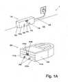
- Fig. 1Ais a schematic perspective view of an exemplary system 1 according to the present invention, including a base station 100, and a mobile robot 200.
- the base station 100 and the robot 200include various components, whose interrelationships are schematically illustrated in Fig. 1B . Referring now to in particular Figs. 1A and 1B .
- the base station 100with which the robot 200 may dock, may include a housing 102.
- the housing 102may accommodate a charger 104, and a transmitter 110.
- the charger 104may include two charge terminals 106 positioned at a generally flat front side 102a of the housing 102, and connected to the mains through a power cord 108 and an internal transformer (not shown).
- the charge terminals 106may connect to two corresponding connection terminals 208 at the front side 202a of the robot 200 to charge its internal rechargeable battery 207.
- the transmitter 110may also be positioned at the front side 102a of the housing 102.
- the transmitter 100includes an infrared light emitter 112, e.g. an infrared laser diode or infrared LED, configured to emit an infrared guide signal. Since the operation of the presently disclosed system 1 does not rely on multiple transmitters 110/infrared light emitters 112 emitting multiple guide signals that differ in (region) code, one infrared light emitter 112 may typically suffice.
- the transmitter 110may be configured to transmit a guide signal 300 into a guide signal reception field 302 bounded by a boundary 304 that includes at least one spatially narrow boundary portion 306 to be tracked by the robot 200 (see Figs.2-4 ).
- the boundary portionmay preferably have a width less than 10 mm, within which width an intensity of the guide signal may drop at least 75%.
- the shape of the guide signal reception field 302, and hence the shape of the boundary portion 306 to be trackedmay be defined by the transmitter 110 and vary for different embodiments.
- Some embodimentsmay include a transmitter 110 that is configured to vary the shape and/or position of the guide signal reception field with time.
- the infrared light emitter 112may embody projection means that enable it to suitably project the guide signal 300 into space, e.g. over or onto the floor.
- Such projection meansmay in themselves be of a generally conventional design, and for instance include one or more (infrared) lenses, mirrors and/or optical masks, and, in particular in the case of an embodiment featuring a dynamic guide signal reception field, one or more electromotors for moving the lenses, mirrors and/or masks.
- the robot 200may include a housing 202, which may at least partly accommodate a drive system 204 - for instance including a set of wheels and an electromotor - for driving the robot across the floor 400, two guide signal sensors 210a, 210b, a controller 206 that is operably connected to both the drive system 204 and the guide signal sensors 210a, 210b and configured to control the drive system based on reference signals outputted by the guide signal sensors, and a rechargeable battery 207 that powers both the drive system 204 and the controller 206.
- a drive system 204for instance including a set of wheels and an electromotor - for driving the robot across the floor 400
- two guide signal sensors 210a, 210ba controller 206 that is operably connected to both the drive system 204 and the guide signal sensors 210a, 210b and configured to control the drive system based on reference signals outputted by the guide signal sensors
- a rechargeable battery 207that powers both the drive system 204 and the controller 206.
- the battery 207may be fitted with the aforementioned two connection terminals 208 that may be disposed at a generally flat front side 202a of the housing 202 to connect to the charge terminals 106 on the base station 100 in a docked condition of the robot 200.
- the robot 200may additionally include (vacuum) suction means, rotatably drivable brushes, and an internal dust container, which, as one skilled in the art will appreciate, are well known features in the art.
- the guide signal sensors 210a, 210bmay be mutually adjacently disposed at the front side 202a of the robot's housing 202, at a common tracking height above the floor.
- the spacing between the guide signal sensors 210a, 210bmay be approximately equal to the width of the boundary portion 306 of the guide signal reception field 304 to be tracked, and typically be less than 10 mm.
- each of the guide signal sensors 120a,bmay include an infrared light receiver 212a, 212b that is sensitive to the infrared guide signal from the infrared light emitter 112 of the base station 100.
- the controller 206 of the robot 200may include a processor configured to execute a movement routine or program involving instructions for the drive system 204 to move the robot 200 across the floor 400 in a certain pattern. More specifically, the controller 206 may be configured to control the drive system 204 at least partly based on the reference signals outputted by the guide signal sensors 210a, 210b, and - in particular when a low battery charge is detected and/or a certain movement routine, e.g. a cleaning routine, has been completed - to thereby actively seek, detect and follow a boundary portion 306 of the guide signal reception field 302 provided by the transmitter 110 of the base station 100.
- a certain movement routinee.g. a cleaning routine
- the controllermay, for instance, drive the robot 200 randomly across the floor until one or both of the guide signal sensors 210a, 210b register the guide signal 300.
- the controller 206may attempt to locate the boundary portion to be tracked 306 by randomly driving towards the boundaries of the guide signal reception field 302 (detectable through the loss of guide signal reception by at least one of the guide signal sensors 210a, 210b), and to determine whether a tracking state may be effected at the detected boundary.
- the controller 206may attempt to locate the boundary portion to be tracked 306 by randomly driving towards the boundaries of the guide signal reception field 302 (detectable through the loss of guide signal reception by at least one of the guide signal sensors 210a, 210b), and to determine whether a tracking state may be effected at the detected boundary.
- the left guide signal sensor 210b of the robot 200is (arbitrarily) selected as the one that, in the tracking state, is positioned substantially on the outside of the tracked boundary portion 306 of the guide signal reception field 302, while the right guide signal sensor 210a is selected as the one that is positioned on the inside of the tracked boundary portion 306. Accordingly, in case a boundary of the guide signal reception field 302 is detected first through loss of guide signal reception for the right guide signal sensor 210a, the controller 206 may conclude that the robot 200 is on the wrong side of the guide signal reception field 302, and drive it to an opposite side, towards the boundary portion 306 to be tracked. Once the boundary portion 306 to be tracked has been located, the controller 206 may initiate a boundary portion following routine that drives the robot 200 along the boundary portion 306 while maintaining the tracking state, so as to smoothly move towards the base station.
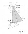
- Figs. 2-4illustrate the system 1 during operation.
- the robot 200is each time shown tracking a boundary portion 306 of the guide signal reception field 302 effected by the transmitter 110 of the base station 100.
- the transmitter 110 on the base station 100is configured to transmit the guide signal 300 into a static, beam-shaped guide signal reception field 302 that extends over the floor 400.
- the guide signal reception field 302may be generally cone-shaped.
- the guide signal reception field 302may thus define two straight non-parallel boundary portions 304 that converge in the direction of the transmitter 110. From the fact that the tracking state in the depicted embodiment is defined as the configuration wherein the left and right guide signal sensors 210b, 210a of the robot 200 are respectively positioned on the outside and on the inside of the tracked boundary portion, it follows that the boundary portion 304 to be tracked is that labelled 306.
- the transmitter 110 on the base station 100has been configured such that the boundary portion 306 to be tracked extends substantially perpendicular to the generally flat front side 102a of the housing 102 of the base station 100. Accordingly, when the robot 200 tracks its way to the base station along the boundary portion 306, it may move seemingly intelligently and in a generally straight line until, eventually, its own generally flat front side 202a neatly mates with the generally flat front side 102a of the housing, and its connection terminals 208 connect to the charge terminals 106.
- the transmitter 110is not configured to transmit the guide signal 300 over the floor 400, as in Fig. 2 , but instead to project the guide signal onto the floor 400.
- Such an embodimentmay rely on the guide signal 300 to be reflected off the floor 400 in order for it to be detectable and trackable by the robot 200.
- the reflection of the guide signal off the floor 400may define the guide signal reception field 302 that, in a floor-parallel plane at the tracking height of the robot 200, is bounded by a boundary portion 306 to be tracked.
- the guide signal sensors 210a, 210bmaybe 'desensitized' to the guide signal incident on the floor 400 by having them face the floor, such that only the reflected guide signal is detectable.
- An advantage of such an embodimentis that it enables the definition of a non-straight or curved guide path, such as the approximately sinusoidal guide path shown in Fig. 3 .
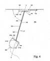
- the transmitter 110is configured to effect a dynamic, i.e. time-variable, guide signal reception field 302, as opposed to the static guide signal reception fields 302 shown in Figs. 2-3 .
- the transmitter 110effects a narrow beam-shaped guide signal reception field 302 that extends over the floor 400; in an alternative embodiment, however, it may be projected onto the floor.
- the guide signal reception field 302may have a central axis A , which, together with an arbitrary floor-parallel reference line L , may include an angle ⁇ .
- the transmitter 110may vary the position of the guide signal reception field 302 relative to the transmitter 110 with time by varying the direction into which it transmits the guide signal 300.
- the transmitter 110may be configured to time-vary the angle ⁇ at which the central axis A of the guide signal reception field 302 extends relative to the reference line L . Consequently, the boundary portion 306 that is being tracked by the mobile robot 200 may extend in a variable boundary direction, and effectively move through space. In case the transmitter 110 varies the boundary direction slowly, and once the robot 200 has started tracking the boundary portion 306, the beam-shaped guide signal reception field 302 may effectively be regarded as a 'tractor beam' by means of which the robot 200 may be reeled in along a dynamic guide path determined by the transmitter 110.
Landscapes
- Engineering & Computer Science (AREA)
- Physics & Mathematics (AREA)
- Aviation & Aerospace Engineering (AREA)
- Radar, Positioning & Navigation (AREA)
- Remote Sensing (AREA)
- General Physics & Mathematics (AREA)
- Automation & Control Theory (AREA)
- Electromagnetism (AREA)
- Control Of Position, Course, Altitude, Or Attitude Of Moving Bodies (AREA)
- Electric Suction Cleaners (AREA)
- Manipulator (AREA)
Description
- The present invention relates to a robot cleaner, capable of autonomous travel and cleaning, and more in particular to a system and a method for guiding the robot cleaner along a certain path, e.g. a path leading to a base station.
US 2005/0231156 discloses a mobile robotic system that includes a charging device and a mobile robot. The charging device is provided with a light emitter and a set of first charging contacts for supplying a charging signal. The mobile robot has a first side provided with a first light sensor, a second side provided with a second light sensor and a set of second charging contacts corresponding to the first charging contacts, a rechargeable battery unit, and a control unit. When charging of the battery unit is intended, the control unit enables movement of the mobile robot until the first light sensor detects light emitted by the light emitter, subsequently enables rotation of the mobile robot until the second light sensor detects the light from the light emitter, and then enables movement of the mobile robot toward the charging device until the first and second charging contacts come into contact.US 2010/0324736 discloses a robot cleaner system including a docking station to form a docking area within a predetermined angle range of a front side thereof, to form docking guide areas which do not overlap each other on the left and right sides of the docking area, and to transmit a docking guide signal such that the docking guide areas are distinguished as a first docking guide area and a second docking guide area according to an arrival distance of the docking guide signal. The robot cleaner system also includes a robot cleaner to move to the docking area along a boundary between the first docking guide area and the second docking guide area when the docking guide signal is sensed and to move along the docking area so as to perform docking when reaching the docking area.JP 58176711 - Robotic cleaning systems are known in the art and may typically include a rechargeable battery-powered, autonomously travelling robot cleaner and a stationary base station. The battery enables the robot's temporary autonomy, but requires periodic charging at the base station. The robot and its base station may therefore be fitted with means configured to ensure that the robot cleaner is capable of locating the base station and returning thereto before its battery is exhausted.
- In many known robotic cleaning systems, such as disclosed in
US 7,729,803 , use is made of a stationary base station fitted with a plurality of signal transmitters, and a mobile robot cleaner fitted with one or more sensors for receiving the signals transmitted by the signal transmitters on the base station. The signals of the various signal transmitters may differ in code, and each of the signals may be transmitted from the base station in a particular direction so as to be receivable in a certain, generally cone-shaped region extending from the base station. Accordingly, the signals may enable the robot to determine its position relative to the base station, and in particular its presence in a certain region, based on the encoding of the signals it receives. - A drawback of region-code based homing systems is that the further the robot is away from its base station, the more inaccurate the determination of its relative position becomes. Since the cone-shaped regions narrow in a direction towards the base station, the positional accuracy improves as the robot approaches the base station. Up to the very last moments of the docking process, however, the positional accuracy may be insufficient to enable the robot to make a clean, straight approach that, for instance, ensures that its connection terminals connect with corresponding charge terminals on the base station. Instead, the robot may appear to wiggle towards the base station as it attempts to progress while maintaining its position within the narrowing cone-shaped region, which may make it look clumsy rather than intelligent.
- It is an object of the present invention to provide for a system and a method that enable a robot cleaner to be guided smoothly along a well-defined path, such as a path leading to a base station. The invention is defined by the independent claims.
- To this end, a first aspect of the present invention is directed to a system. The system may comprise a base station including a transmitter configured to transmit a guide signal into a spatially bounded guide signal reception field. The system may also comprise a mobile robot. The robot may include a drive system configured to drive the robot across a floor; two mutually adjacently disposed guide signal sensors, each of which is configured to generate a reference signal that reflects its reception of the guide signal; and a controller that is operably connected to the drive system and the guide signal sensors. The controller may be configured to control the drive system to move the robot along a boundary portion of the guide signal reception field while, based on said reference signals, maintaining a tracking state in which a first of said guide signal sensors is positioned substantially on a first side of said boundary portion, substantially inside of the guide signal reception field, and a second of said guide signal sensors is positioned substantially on a second side of said boundary portion, substantially outside of the guide signal reception field.
- In the present invention the transmitter may transmit a guide signal into a guide signal reception field, i.e. a region of space within which the guide signal is receivable, and that is bounded by at least one, normally non-physical boundary. On one side of the boundary, within the guide signal reception field, reception of the guide signal may be possible, while on the other side of the boundary, outside of the guide signal reception field, no guide signal may be detectable. The boundary itself may define at least one relatively sharp, i.e. spatially narrow, boundary portion that can be regarded as a guide path or trail to be followed by the mobile robot. To be able to follow this guide path, the robot may be fitted with two adjacently disposed guide signal sensors, each capable of detecting the guide signal and of outputting a reference signal that is indicative of an intensity of the detected guide signal. A significant difference in the strengths of the reference signals may indicate that the guide signal sensors are substantially located on opposite sides of the boundary portion, and thus that the robot is positioned on the guide path laid out by the transmitter. The state in which the sensors are located on opposite sides of the boundary portion may be referred to as the 'tracking state', and this tracking state may be maintained as the robot moves along, and so tracks, the guide path. In particular when the guide path is chosen little fanciful, the above approach may enable the robot to accurately track it in a smooth, seemingly intelligent motion.
- In accordance with the present invention, the transmitter is configured to project the guide signalonto the floor. Such an embodiment relies on the guide signal to be reflected off the floor in order for it to be detectable and trackable by the robot. Accordingly, the reflection of the guide signal off the floor, rather than the guide signal incident on the floor, defines the guide signal reception field that, in a floor-parallel plane at the tracking height of the robot, is bounded by a boundary portion to be tracked. The guide signal sensors may be 'desensitized' to the guide signal incident on the floor by having them face the floor, such that only the reflected guide signal is detectable. An advantage of such an embodiment is that it enables the definition of a non-straight or curved guide path.
- The guide signal may in principle be any type of signal capable of being transmitted to effect a guide signal reception field that is bounded by at least one boundary portion across which an intensity of the guide signal falls off rapidly enough to accurately define a narrow and easily detectable guide path. Suitable guide signal types may include acoustic signals, e.g. ultrasound signals, and electromagnetic signals, in particular non-visible light signals, such as ultraviolet light signals or infrared light signals. In an embodiment of the system employing infrared light, for instance, the transmitter may include an infrared light emitter configured to emit an infrared guide signal, while each of the guide signal sensors may include an infrared light receiver sensitive to the infrared guide signal from the infrared light emitter. Embodiments of the disclosed system based on electromagnetic guide signals, and especially infrared guide signals, generally allow for sharply defined guide signal reception fields and thus accurately defined guide paths at relatively low implementation costs.
- In an operational condition of the robot on the floor, the guide signal sensors may be disposed at a preferably common tracking height above the floor; in case the guide signal sensors are not disposed at a same or common height, the tracking height may be defined as the average height of the guide signal sensors. Accordingly, the robot may be configured to track a boundary portion of the guide signal reception field at said tracking height (i.e. the boundary portion may coincide with a curve of intersection between the guide signal reception field and a floor-parallel plane at the tracking height). During tracking, the robot may attempt to maintain the tracking state in which one of the guide signal sensors is positioned substantially on a first side of said boundary portion, inside of the guide signal reception field, and the other guide signal sensors is positioned substantially on a second side of said boundary portion, outside of the guide signal reception field. The spacing between the guide signal sensors may thus be approximately equal to a width of the boundary portion at the tracking height, so as to allow for both optimal contrast in the intensity of the guide signal as detected by the two guide signal sensors, and accurate and smooth tracking thereof. It will be appreciated that a guide signal sensor spacing that is not tailored to the width of the boundary portion may prevent proper tracking. A guide signal sensor spacing that is significantly smaller than the width of the boundary portion, for example, may prevent the robot from effecting the tracking state in the first place, while a spacing that significantly exceeds the width of the boundary portion may inhibit accurate tracking as it may allow the robot to stray off the guide path without abandoning the tracking state. In this regard, the width of the boundary portion may be construed to be the (minimum) distance across which the guide signal intensity drops at least 75%, and preferably even from full to zero. In a preferred embodiment, the transmitter may be configured to ensure that the at least one boundary portion to be tracked by the robot has a width less than 10 mm, and more preferably less than 5 mm.
- The shape of the guide signal reception field, and hence the shape of the boundary portion to be tracked, may be defined by the transmitter and vary for different embodiments. Some embodiments may even include a transmitter that is configured to vary the shape and/or position of the guide signal reception field with time.
- In a relatively simple embodiment, for example, the transmitter may be configured to transmit the guide signal into a static, beam-shaped guide signal reception field that extends over the floor. In a floor-parallel plane at the tracking height, the beam may preferably define at least one straight boundary portion. In a practical embodiment the guide signal reception field may be generally cone-shaped, and thus have two straight non-parallel boundaries that extend from the transmitter in said floor-parallel plane at the tracking height.
- In yet another embodiment, the guide signal reception field may not be static, but be dynamic, and for instance vary in location (relative to the normally stationary position of the transmitter) and/or shape with time. For example, in one such embodiment, the transmitter may be configured to effect a guide signal reception field that, seen in a floor-parallel plane at the tracking height of the robot, defines an essentially straight boundary portion that extends in a certain boundary direction from the transmitter, and wherein the transmitter is further configured to vary that boundary direction. The transmitter may in particular vary the boundary direction slowly once the robot has started tracking the boundary portion, such that the robot can be virtually 'tethered' or 'reeled in' along a dynamic guide path determined by the transmitter.
- These and other features and advantages of the invention will be more fully understood from the following detailed description of certain embodiments of the invention, taken together with the accompanying drawings, which are meant to illustrate and not to limit the invention.
Fig. 1A is a schematic perspective view of an exemplary system according to the present invention, including a base station and a mobile robot capable of docking therewith;Fig. 1B schematically illustrates the relations between the various components of the system shown inFig. 1A ;Fig. 2 is a schematic top view of the system ofFig. 1 during operation, illustrating how the robot follows a straight boundary portion of a generally cone-shaped guide signal reception field generated by a transmitter of the base station;Fig. 3 is a schematic top view of the system ofFig. 1 during operation, illustrating how the robot follows a curved boundary portion of a guide signal reception field generated by a transmitter of the base station that projects the guide signal onto the floor.Fig. 4 is a schematic top view of the system ofFig. 1 during operation, illustrating how the robot follows a dynamic or moving boundary portion of a guide signal reception field, as if it were 'tethered' to the base station that generates it.Fig. 1A is a schematic perspective view of an exemplary system 1 according to the present invention, including abase station 100, and amobile robot 200. Thebase station 100 and therobot 200 include various components, whose interrelationships are schematically illustrated inFig. 1B . Referring now to in particularFigs. 1A and1B .- The
base station 100, with which therobot 200 may dock, may include ahousing 102. Thehousing 102 may accommodate acharger 104, and atransmitter 110. Thecharger 104 may include twocharge terminals 106 positioned at a generally flatfront side 102a of thehousing 102, and connected to the mains through apower cord 108 and an internal transformer (not shown). In a docked state of therobot 200, thecharge terminals 106 may connect to twocorresponding connection terminals 208 at thefront side 202a of therobot 200 to charge its internalrechargeable battery 207. - The
transmitter 110 may also be positioned at thefront side 102a of thehousing 102. In the depicted embodiment, thetransmitter 100 includes aninfrared light emitter 112, e.g. an infrared laser diode or infrared LED, configured to emit an infrared guide signal. Since the operation of the presently disclosed system 1 does not rely onmultiple transmitters 110/infrared light emitters 112 emitting multiple guide signals that differ in (region) code, oneinfrared light emitter 112 may typically suffice. In general, thetransmitter 110 may be configured to transmit aguide signal 300 into a guidesignal reception field 302 bounded by aboundary 304 that includes at least one spatiallynarrow boundary portion 306 to be tracked by the robot 200 (seeFigs.2-4 ). The boundary portion may preferably have a width less than 10 mm, within which width an intensity of the guide signal may drop at least 75%. - As will be clarified with reference to
Figs. 2-4 below, the shape of the guidesignal reception field 302, and hence the shape of theboundary portion 306 to be tracked, may be defined by thetransmitter 110 and vary for different embodiments. Some embodiments may include atransmitter 110 that is configured to vary the shape and/or position of the guide signal reception field with time. To effect a guidesignal reception field 302 with a desired static ordynamic boundary portion 306, theinfrared light emitter 112 may embody projection means that enable it to suitably project theguide signal 300 into space, e.g. over or onto the floor. Such projection means may in themselves be of a generally conventional design, and for instance include one or more (infrared) lenses, mirrors and/or optical masks, and, in particular in the case of an embodiment featuring a dynamic guide signal reception field, one or more electromotors for moving the lenses, mirrors and/or masks. - The
robot 200 may include ahousing 202, which may at least partly accommodate a drive system 204 - for instance including a set of wheels and an electromotor - for driving the robot across thefloor 400, twoguide signal sensors controller 206 that is operably connected to both thedrive system 204 and theguide signal sensors rechargeable battery 207 that powers both thedrive system 204 and thecontroller 206. Thebattery 207 may be fitted with the aforementioned twoconnection terminals 208 that may be disposed at a generally flatfront side 202a of thehousing 202 to connect to thecharge terminals 106 on thebase station 100 in a docked condition of therobot 200. In embodiment wherein therobot 200 is a robotic vacuum cleaner, it may additionally include (vacuum) suction means, rotatably drivable brushes, and an internal dust container, which, as one skilled in the art will appreciate, are well known features in the art. - The
guide signal sensors front side 202a of the robot'shousing 202, at a common tracking height above the floor. The spacing between theguide signal sensors boundary portion 306 of the guidesignal reception field 304 to be tracked, and typically be less than 10 mm. It is understood that each of the guide signal sensors 120a,b may include aninfrared light receiver infrared light emitter 112 of thebase station 100. - The
controller 206 of therobot 200 may include a processor configured to execute a movement routine or program involving instructions for thedrive system 204 to move therobot 200 across thefloor 400 in a certain pattern. More specifically, thecontroller 206 may be configured to control thedrive system 204 at least partly based on the reference signals outputted by theguide signal sensors boundary portion 306 of the guidesignal reception field 302 provided by thetransmitter 110 of thebase station 100. To locate the guidesignal reception field 302, the controller may, for instance, drive therobot 200 randomly across the floor until one or both of theguide signal sensors guide signal 300. Once the guidesignal reception field 302 has been located and optionally entered, thecontroller 206 may attempt to locate the boundary portion to be tracked 306 by randomly driving towards the boundaries of the guide signal reception field 302 (detectable through the loss of guide signal reception by at least one of theguide signal sensors Figs. 2-4 , the leftguide signal sensor 210b of therobot 200 is (arbitrarily) selected as the one that, in the tracking state, is positioned substantially on the outside of the trackedboundary portion 306 of the guidesignal reception field 302, while the rightguide signal sensor 210a is selected as the one that is positioned on the inside of the trackedboundary portion 306. Accordingly, in case a boundary of the guidesignal reception field 302 is detected first through loss of guide signal reception for the rightguide signal sensor 210a, thecontroller 206 may conclude that therobot 200 is on the wrong side of the guidesignal reception field 302, and drive it to an opposite side, towards theboundary portion 306 to be tracked. Once theboundary portion 306 to be tracked has been located, thecontroller 206 may initiate a boundary portion following routine that drives therobot 200 along theboundary portion 306 while maintaining the tracking state, so as to smoothly move towards the base station. - Various contemplated implementations of the system 1 according to the present invention will now be described briefly with reference to
Figs. 2-4 , which illustrate the system 1 during operation. Therobot 200 is each time shown tracking aboundary portion 306 of the guidesignal reception field 302 effected by thetransmitter 110 of thebase station 100. - In the embodiment of
Fig. 2 , thetransmitter 110 on thebase station 100 is configured to transmit theguide signal 300 into a static, beam-shaped guidesignal reception field 302 that extends over thefloor 400. The guidesignal reception field 302 may be generally cone-shaped. In a floor-parallel plane at the tracking height of therobot 200, the guidesignal reception field 302 may thus define two straightnon-parallel boundary portions 304 that converge in the direction of thetransmitter 110. From the fact that the tracking state in the depicted embodiment is defined as the configuration wherein the left and rightguide signal sensors robot 200 are respectively positioned on the outside and on the inside of the tracked boundary portion, it follows that theboundary portion 304 to be tracked is that labelled 306. - It may be noted that the
transmitter 110 on thebase station 100 has been configured such that theboundary portion 306 to be tracked extends substantially perpendicular to the generally flatfront side 102a of thehousing 102 of thebase station 100. Accordingly, when therobot 200 tracks its way to the base station along theboundary portion 306, it may move seemingly intelligently and in a generally straight line until, eventually, its own generally flatfront side 202a neatly mates with the generally flatfront side 102a of the housing, and itsconnection terminals 208 connect to thecharge terminals 106. - In the embodiment of
Fig. 3 , thetransmitter 110 is not configured to transmit theguide signal 300over thefloor 400, as inFig. 2 , but instead to project the guide signalonto thefloor 400. Such an embodiment may rely on theguide signal 300 to be reflected off thefloor 400 in order for it to be detectable and trackable by therobot 200. Accordingly, the reflection of the guide signal off thefloor 400, rather than the guide signal incident on the floor, may define the guidesignal reception field 302 that, in a floor-parallel plane at the tracking height of therobot 200, is bounded by aboundary portion 306 to be tracked. Theguide signal sensors floor 400 by having them face the floor, such that only the reflected guide signal is detectable. An advantage of such an embodiment is that it enables the definition of a non-straight or curved guide path, such as the approximately sinusoidal guide path shown inFig. 3 . - In the embodiment of
Fig. 4 , thetransmitter 110 is configured to effect a dynamic, i.e. time-variable, guidesignal reception field 302, as opposed to the static guide signal reception fields 302 shown inFigs. 2-3 . In the depicted situation, thetransmitter 110 effects a narrow beam-shaped guidesignal reception field 302 that extends over thefloor 400; in an alternative embodiment, however, it may be projected onto the floor. The guidesignal reception field 302 may have a central axisA, which, together with an arbitrary floor-parallel reference lineL, may include an angle θ. As illustrated, thetransmitter 110 may vary the position of the guidesignal reception field 302 relative to thetransmitter 110 with time by varying the direction into which it transmits theguide signal 300. That is, thetransmitter 110 may be configured to time-vary the angle θ at which the central axisA of the guidesignal reception field 302 extends relative to the reference lineL. Consequently, theboundary portion 306 that is being tracked by themobile robot 200 may extend in a variable boundary direction, and effectively move through space. In case thetransmitter 110 varies the boundary direction slowly, and once therobot 200 has started tracking theboundary portion 306, the beam-shaped guidesignal reception field 302 may effectively be regarded as a 'tractor beam' by means of which therobot 200 may be reeled in along a dynamic guide path determined by thetransmitter 110. - 1
- system
- 100
- base station
- 102
- housing
- 102a
- front side of base station housing
- 104
- charger
- 106
- charge terminals
- 108
- power cord
- 110
- transmitter
- 112
- infrared light emitter
- 200
- robot
- 202
- housing
- 202a
- front side of robot housing
- 204
- drive system
- 206
- controller
- 207
- rechargeable battery
- 208
- charge connection terminals
- 210a,b
- first (a) and second (b) guide signal sensor
- 212a,b
- infrared light receiver of first (a) and second (b) guide signal sensor
- 300
- infrared guide signal
- 302
- guide signal reception field
- 304
- boundary of guide signal reception field
- 306
- tracked boundary portion of guide signal reception field
- 400
- floor
- A
- central axis of guide signal reception field
- L
- reference line
- θ
- angle of central axis of guide signal reception field
Claims (15)
- A system (1), comprising:a base station (100) including a transmitter (110) that is configured to transmit a guide signal (300) into a guide signal reception field (302) spatially bounded by at least one boundary portion (306);a mobile robot (200) including:characterised in thata drive system (204) configured to drive the mobile robot across a floor (400);two mutually adjacently disposed guide signal sensors (210a, 210b), each of which is configured to generate a reference signal that reflects its reception of the guide signal; anda controller (206) that is operably connected to the drive system (204) and the guide signal sensors (210a, 210b), and configured to control the drive system (204) to move the mobile robot along the at least one boundary portion (306) of the guide signal reception field (302) while, based on said reference signals, maintaining a tracking state in which a first of said guide signal sensors (210a) is positioned substantially on a first side of said boundary portion (306), inside of the guide signal reception field (302), and a second of said guide signal sensors (210b) is positioned substantially on a second side of said boundary portion (306), outside of the guide signal reception field (302),the transmitter (110) is configured to project the guide signal (300) onto the floor (400), such that the guide signal reception field (302) is at least partly defined by a reflection of the guide signal off the floor, andin that said guide signal sensors (210a, 210b) are arranged for detecting said reflection of the guide signal off the floor.
- The system according to claim 1, wherein the boundary portion (306) has a width of less than 10 mm, within which width an intensity of the guide signal drops at least 75%.
- The system according to claim 1 or 2, wherein the transmitter (110) includes an infrared light emitter (112) configured to emit an infrared guide signal (300), and
wherein each of the guide signal sensors (210a, 210b) includes an infrared light receiver (212a, 212b) sensitive to the infrared guide signal from the infrared light emitter (112). - The system according to any of the claims 1-3, wherein, in an operational condition of the mobile robot (200) on the floor (400), the guide signal sensors (210a, 210b) are disposed at a substantially same tracking height above the floor (400).
- The system according to any of the claims 1-4, wherein the boundary portion (306), as seen in a top view perpendicular to the floor (400), is substantially straight.
- The system according to any of the claims 1-4, wherein the boundary portion (306), as seen in a top view perpendicular to the floor (400) is curved.
- The system according to any of the claims 1-6, wherein the transmitter (110) is configured to vary the position of the guide signal reception field (302) relative to the transmitter with time, so as to vary the position of the boundary portion (306).
- The system according to any of the claims 1-7, wherein the transmitter (110) is configured to vary the shape of the guide signal reception field (302) with time, so as to vary the shape of the boundary portion (306).
- The system according to any of the claims 1-6, wherein the base station (100) includes a housing (102) with a generally flat front side (102a) having at least part of the transmitter (110) mounted therein,
wherein the mobile robot (200) includes a housing (202) with a generally flat front side (202a) having said guide signal sensors (210a, 210b) mounted thereon, and
wherein the transmitter (100) is configured to effect a guide signal reception field (302) whose at least one boundary portion (306) extends substantially perpendicular to said front side (102a) of the housing (102) of the base station (100), at least immediately adjacent said front side (102a). - The system according to any of the claims 1-9, wherein the mobile robot (200) is a robotic vacuum cleaner.
- A mobile robot (200) for tracking a boundary portion (306) of a spatially bounded guide signal reception field (302) into which a guide signal (300) is transmitted by a transmitter (110), said mobile robot comprising:a drive system (204) configured to drive the mobile robot across a floor (400);two mutually adjacently disposed guide signal sensors (210a, 210b), each of which is configured to generate a reference signal that reflects its reception of the guide signal; anda controller (206) that is operably connected to the drive system (204) and the guide signal sensors (210a, 210b), and configured to control the drive system (204) to move the mobile robot along a boundary portion (306) of the guide signal reception field (302) while, based on said reference signals, maintaining a tracking state in which a first of said guide signal sensors (210a) is positioned substantially on a first side of said boundary portion (306), inside of the guide signal reception field (302), and a second of said guide signal sensors (210b) is positioned substantially on a second side of said boundary portion (306), outside of the guide signal reception field (302),characterised in thatsaid guide signal sensors (210a, 210b) are arranged for detecting a reflection of the guide signal off the floor.
- The mobile robot according to claim 11,
wherein each of the guide signal sensors (210a, 210b) includes an infrared light receiver (212a, 212b) sensitive to an infrared guide signal. - The mobile robot according to any of the claims 11-12, wherein, in an operational condition of the mobile robot (200) on the floor (400), the guide signal sensors (210a, 210b) are disposed at a substantially same tracking height above the floor (400).
- The mobile robot according to any of the claims 11-13, wherein the guide signal sensors (210a, 210b) are spaced apart less than 10 mm.
- A method of guiding a mobile robot, the method comprising:providing a transmitter (110), and having said transmitter transmit a guide signal (300) into a spatially bounded guide signal reception field (302);providing the mobile robot (200) including two mutually adjacently disposed guide signal sensors (210a, 210b), each configured to generate a reference signal that reflects its reception of the guide signal; andmoving the mobile robot (200) along a boundary portion (306) of the guide signal reception field (302) while, based on said reference signals, maintaining a tracking state in which a first of said guide signal sensors (210a) is positioned substantially on a first side of said boundary portion (306), inside of the guide signal reception field (302), and a second of said guide signal sensors (210b) is positioned substantially on a second side of said boundary portion (306), outside of the guide signal reception field (302),characterised in thatthe transmitter (110) is configured to project the guide signal (300) onto the floor (400), such that the guide signal reception field (302) is at least partly defined by a reflection of the guide signal off the floor, andin that said guide signal sensors (210a, 210b) are arranged for detecting said reflection of the guide signal off the floor.
Applications Claiming Priority (2)
| Application Number | Priority Date | Filing Date | Title |
|---|---|---|---|
| US201261656572P | 2012-06-07 | 2012-06-07 | |
| PCT/IB2013/054245WO2013182941A1 (en) | 2012-06-07 | 2013-05-22 | System and method for guiding a robot cleaner along a path |
Publications (2)
| Publication Number | Publication Date |
|---|---|
| EP2859423A1 EP2859423A1 (en) | 2015-04-15 |
| EP2859423B1true EP2859423B1 (en) | 2016-01-06 |
Family
ID=48790504
Family Applications (1)
| Application Number | Title | Priority Date | Filing Date |
|---|---|---|---|
| EP13736963.3AActiveEP2859423B1 (en) | 2012-06-07 | 2013-05-22 | System and method for guiding a robot cleaner along a path |
Country Status (6)
| Country | Link |
|---|---|
| US (1) | US9280158B2 (en) |
| EP (1) | EP2859423B1 (en) |
| JP (1) | JP5860998B2 (en) |
| CN (1) | CN104395849B (en) |
| RU (1) | RU2628970C2 (en) |
| WO (1) | WO2013182941A1 (en) |
Families Citing this family (27)
| Publication number | Priority date | Publication date | Assignee | Title |
|---|---|---|---|---|
| GB2509991B (en)* | 2013-01-22 | 2015-03-11 | Dyson Technology Ltd | Docking station for a mobile robot |
| GB2509989B (en)* | 2013-01-22 | 2015-03-04 | Dyson Technology Ltd | Docking station for a mobile robot |
| KR101620449B1 (en)* | 2014-06-26 | 2016-05-12 | 삼성전자 주식회사 | Robot cleaner and method for controlling the same |
| CN105302130A (en)* | 2014-07-28 | 2016-02-03 | 东盛精密科技有限公司 | Mobile guidance device and mobile guidance method |
| SE538372C2 (en) | 2014-12-23 | 2016-05-31 | Husqvarna Ab | Improved map generation by a robotic work tool |
| CN105809944A (en)* | 2014-12-30 | 2016-07-27 | Tcl集团股份有限公司 | Robot, charging device, charging alignment method and charging system |
| CN105259918B (en)* | 2015-09-18 | 2018-12-04 | 莱克电气股份有限公司 | Automatic charging and returning method for robot dust collector |
| JP2017084069A (en)* | 2015-10-27 | 2017-05-18 | 株式会社マキタ | Self-travel type dust collection robot and reflector, and travel control method of self-travel type dust collection robot |
| CN107632595B (en)* | 2016-07-18 | 2020-09-22 | 苏州宝时得电动工具有限公司 | Path returning method of automatic walking equipment, automatic walking equipment and path returning system |
| CN107153416A (en)* | 2016-03-02 | 2017-09-12 | 苏州宝时得电动工具有限公司 | Direction of travel recognition methods and intelligent sliding motor-car and intelligent mobile system |
| CN106909140B (en)* | 2015-12-22 | 2021-02-09 | 苏州宝时得电动工具有限公司 | Route regression method and system |
| CN106026288A (en)* | 2016-07-18 | 2016-10-12 | 旗瀚科技有限公司 | Robot automatic charging system and charging method thereof |
| WO2018217431A1 (en) | 2017-05-25 | 2018-11-29 | Covidien Lp | Robotic surgical system with automated guidance |
| CN108873879B (en) | 2017-09-25 | 2022-03-04 | 北京石头创新科技有限公司 | Autonomous mobile robot and its pile finding method, control device and intelligent cleaning system |
| CN108852174B (en) | 2017-09-25 | 2022-02-25 | 北京石头创新科技有限公司 | Autonomous mobile robot and pile searching method, control device and intelligent cleaning system thereof |
| US11687092B2 (en) | 2018-04-23 | 2023-06-27 | Sharkninja Operating Llc | Techniques for bounding cleaning operations of a robotic surface cleaning device within a region of interest |
| US10831212B2 (en) | 2018-09-19 | 2020-11-10 | International Business Machines Corporation | Autonomous roving vehicle management using laser barriers |
| CA3121163C (en)* | 2018-11-28 | 2023-09-05 | Sharkninja Operating Llc | Optical beacon for autonomous device and autonomous device configured to use the same |
| CN111374594B (en)* | 2018-12-27 | 2023-05-16 | 北京奇虎科技有限公司 | Super boundary processing method, device, electronic equipment and computer readable storage medium |
| CN109933071B (en)* | 2019-04-01 | 2020-07-14 | 珠海市一微半导体有限公司 | A control method of robot back to seat |
| US11597104B2 (en)* | 2019-07-31 | 2023-03-07 | X Development Llc | Mobile robot sensor configuration |
| CN112857368B (en)* | 2019-11-12 | 2024-04-09 | 苏州宝时得电动工具有限公司 | Mower navigation method and device and mower |
| EP3968051B1 (en)* | 2020-09-15 | 2024-10-30 | Infineon Technologies AG | Guiding system for a robot, base station including such a guiding system, and method for guiding a robot |
| DE102020132205A1 (en)* | 2020-12-03 | 2022-06-09 | Vorwerk & Co. Interholding Gesellschaft mit beschränkter Haftung | Self-propelled tillage implement with at least one fall sensor |
| GB2612567B (en)* | 2021-01-22 | 2023-11-22 | Dyson Technology Ltd | Autonomous surface treatment apparatus |
| WO2023018947A1 (en) | 2021-08-13 | 2023-02-16 | Sharkninja Operating Llc | Robotic cleaner |
| CN116300841A (en)* | 2021-12-07 | 2023-06-23 | 苏州宝时得电动工具有限公司 | Automatic working system, automatic working method and computer readable storage medium |
Family Cites Families (15)
| Publication number | Priority date | Publication date | Assignee | Title |
|---|---|---|---|---|
| US2311156A (en)* | 1940-09-06 | 1943-02-16 | Lloyd V Casto | Decorating and molding of transparent sheets |
| JPS58176711A (en) | 1982-04-10 | 1983-10-17 | Kubota Ltd | Work truck with control sensor of travelling direction |
| AU767561B2 (en)* | 2001-04-18 | 2003-11-13 | Samsung Kwangju Electronics Co., Ltd. | Robot cleaner, system employing the same and method for reconnecting to external recharging device |
| KR100533829B1 (en)* | 2003-07-29 | 2005-12-07 | 삼성광주전자 주식회사 | an air-cleaning robot and system thereof |
| GB2404331B (en)* | 2003-07-29 | 2005-06-29 | Samsung Gwanju Electronics Co | Robot cleaner equipped with negative-ion generator |
| TWI258259B (en)* | 2004-04-20 | 2006-07-11 | Jason Yan | Automatic charging system of mobile robotic electronic device |
| US7456596B2 (en)* | 2005-08-19 | 2008-11-25 | Cisco Technology, Inc. | Automatic radio site survey using a robot |
| KR100645381B1 (en)* | 2005-08-31 | 2006-11-14 | 삼성광주전자 주식회사 | External charge return device and return method for robot cleaner |
| WO2008149273A2 (en)* | 2007-06-05 | 2008-12-11 | Koninklijke Philips Electronics N.V. | A system as well as a method for controlling a self moving robot |
| US8489234B2 (en)* | 2007-07-18 | 2013-07-16 | Lg Electronics Inc. | Mobile robot and controlling method thereof |
| EP2263510B1 (en)* | 2009-06-19 | 2017-09-13 | Samsung Electronics Co., Ltd. | Robot cleaner and method of its travel control |
| KR101672787B1 (en)* | 2009-06-19 | 2016-11-17 | 삼성전자주식회사 | Robot cleaner and docking station and robot cleaner system having the same and control method thereof |
| US8825256B2 (en) | 2009-06-30 | 2014-09-02 | Lg Electronics Inc. | Charging device of robot cleaner |
| US20110040437A1 (en)* | 2009-08-17 | 2011-02-17 | James Lynch | Robot Confinement Method |
| CN202189275U (en)* | 2011-07-13 | 2012-04-11 | 东华大学 | Circuit applied for warehouse autonomous patrol dolly with automatic charging capability |
- 2013
- 2013-05-22RURU2014154405Apatent/RU2628970C2/ennot_activeIP Right Cessation
- 2013-05-22CNCN201380023600.3Apatent/CN104395849B/enactiveActive
- 2013-05-22EPEP13736963.3Apatent/EP2859423B1/enactiveActive
- 2013-05-22USUS14/405,520patent/US9280158B2/enactiveActive
- 2013-05-22WOPCT/IB2013/054245patent/WO2013182941A1/enactiveApplication Filing
- 2013-05-22JPJP2015515608Apatent/JP5860998B2/ennot_activeExpired - Fee Related
Also Published As
| Publication number | Publication date |
|---|---|
| RU2628970C2 (en) | 2017-08-23 |
| US9280158B2 (en) | 2016-03-08 |
| US20150134144A1 (en) | 2015-05-14 |
| JP5860998B2 (en) | 2016-02-16 |
| JP2015519965A (en) | 2015-07-16 |
| EP2859423A1 (en) | 2015-04-15 |
| CN104395849B (en) | 2017-03-22 |
| CN104395849A (en) | 2015-03-04 |
| WO2013182941A1 (en) | 2013-12-12 |
| RU2014154405A (en) | 2016-07-27 |
Similar Documents
| Publication | Publication Date | Title |
|---|---|---|
| EP2859423B1 (en) | System and method for guiding a robot cleaner along a path | |
| US11292136B2 (en) | Mobile robot docking systems and methods | |
| JP6758402B2 (en) | Autonomous robot automatic docking and energy management systems and methods | |
| EP3876806B1 (en) | Optical indicium for communicating information to autonomous devices | |
| CN213850443U (en) | Robot cleaner and robot system | |
| EP3593692B1 (en) | Vacuum cleaner and control method thereof | |
| EP2312411B1 (en) | Docking station for a cleaning robot with duration coded guiding signals | |
| KR102329614B1 (en) | Cleaner and controlling method thereof | |
| EP3317792B1 (en) | Robot navigational sensor system | |
| US7133746B2 (en) | Autonomous machine for docking with a docking station and method for docking | |
| KR20160048347A (en) | An automatic docking system of mobile robot charging station and the method thereof | |
| CN113854900B (en) | Self-moving robot |
Legal Events
| Date | Code | Title | Description |
|---|---|---|---|
| PUAI | Public reference made under article 153(3) epc to a published international application that has entered the european phase | Free format text:ORIGINAL CODE: 0009012 | |
| 17P | Request for examination filed | Effective date:20150107 | |
| AK | Designated contracting states | Kind code of ref document:A1 Designated state(s):AL AT BE BG CH CY CZ DE DK EE ES FI FR GB GR HR HU IE IS IT LI LT LU LV MC MK MT NL NO PL PT RO RS SE SI SK SM TR | |
| AX | Request for extension of the european patent | Extension state:BA ME | |
| GRAP | Despatch of communication of intention to grant a patent | Free format text:ORIGINAL CODE: EPIDOSNIGR1 | |
| INTG | Intention to grant announced | Effective date:20150710 | |
| DAX | Request for extension of the european patent (deleted) | ||
| GRAS | Grant fee paid | Free format text:ORIGINAL CODE: EPIDOSNIGR3 | |
| GRAA | (expected) grant | Free format text:ORIGINAL CODE: 0009210 | |
| AK | Designated contracting states | Kind code of ref document:B1 Designated state(s):AL AT BE BG CH CY CZ DE DK EE ES FI FR GB GR HR HU IE IS IT LI LT LU LV MC MK MT NL NO PL PT RO RS SE SI SK SM TR | |
| REG | Reference to a national code | Ref country code:GB Ref legal event code:FG4D | |
| REG | Reference to a national code | Ref country code:CH Ref legal event code:EP | |
| REG | Reference to a national code | Ref country code:IE Ref legal event code:FG4D | |
| REG | Reference to a national code | Ref country code:AT Ref legal event code:REF Ref document number:769373 Country of ref document:AT Kind code of ref document:T Effective date:20160215 | |
| REG | Reference to a national code | Ref country code:DE Ref legal event code:R096 Ref document number:602013004532 Country of ref document:DE | |
| REG | Reference to a national code | Ref country code:LT Ref legal event code:MG4D | |
| REG | Reference to a national code | Ref country code:NL Ref legal event code:MP Effective date:20160106 | |
| REG | Reference to a national code | Ref country code:AT Ref legal event code:MK05 Ref document number:769373 Country of ref document:AT Kind code of ref document:T Effective date:20160106 | |
| REG | Reference to a national code | Ref country code:FR Ref legal event code:PLFP Year of fee payment:4 | |
| PG25 | Lapsed in a contracting state [announced via postgrant information from national office to epo] | Ref country code:NL Free format text:LAPSE BECAUSE OF FAILURE TO SUBMIT A TRANSLATION OF THE DESCRIPTION OR TO PAY THE FEE WITHIN THE PRESCRIBED TIME-LIMIT Effective date:20160106 | |
| PG25 | Lapsed in a contracting state [announced via postgrant information from national office to epo] | Ref country code:GR Free format text:LAPSE BECAUSE OF FAILURE TO SUBMIT A TRANSLATION OF THE DESCRIPTION OR TO PAY THE FEE WITHIN THE PRESCRIBED TIME-LIMIT Effective date:20160407 Ref country code:FI Free format text:LAPSE BECAUSE OF FAILURE TO SUBMIT A TRANSLATION OF THE DESCRIPTION OR TO PAY THE FEE WITHIN THE PRESCRIBED TIME-LIMIT Effective date:20160106 Ref country code:IT Free format text:LAPSE BECAUSE OF FAILURE TO SUBMIT A TRANSLATION OF THE DESCRIPTION OR TO PAY THE FEE WITHIN THE PRESCRIBED TIME-LIMIT Effective date:20160106 Ref country code:HR Free format text:LAPSE BECAUSE OF FAILURE TO SUBMIT A TRANSLATION OF THE DESCRIPTION OR TO PAY THE FEE WITHIN THE PRESCRIBED TIME-LIMIT Effective date:20160106 Ref country code:NO Free format text:LAPSE BECAUSE OF FAILURE TO SUBMIT A TRANSLATION OF THE DESCRIPTION OR TO PAY THE FEE WITHIN THE PRESCRIBED TIME-LIMIT Effective date:20160406 Ref country code:ES Free format text:LAPSE BECAUSE OF FAILURE TO SUBMIT A TRANSLATION OF THE DESCRIPTION OR TO PAY THE FEE WITHIN THE PRESCRIBED TIME-LIMIT Effective date:20160106 | |
| PG25 | Lapsed in a contracting state [announced via postgrant information from national office to epo] | Ref country code:PT Free format text:LAPSE BECAUSE OF FAILURE TO SUBMIT A TRANSLATION OF THE DESCRIPTION OR TO PAY THE FEE WITHIN THE PRESCRIBED TIME-LIMIT Effective date:20160506 Ref country code:BE Free format text:LAPSE BECAUSE OF NON-PAYMENT OF DUE FEES Effective date:20160531 Ref country code:LV Free format text:LAPSE BECAUSE OF FAILURE TO SUBMIT A TRANSLATION OF THE DESCRIPTION OR TO PAY THE FEE WITHIN THE PRESCRIBED TIME-LIMIT Effective date:20160106 Ref country code:SE Free format text:LAPSE BECAUSE OF FAILURE TO SUBMIT A TRANSLATION OF THE DESCRIPTION OR TO PAY THE FEE WITHIN THE PRESCRIBED TIME-LIMIT Effective date:20160106 Ref country code:AT Free format text:LAPSE BECAUSE OF FAILURE TO SUBMIT A TRANSLATION OF THE DESCRIPTION OR TO PAY THE FEE WITHIN THE PRESCRIBED TIME-LIMIT Effective date:20160106 Ref country code:PL Free format text:LAPSE BECAUSE OF FAILURE TO SUBMIT A TRANSLATION OF THE DESCRIPTION OR TO PAY THE FEE WITHIN THE PRESCRIBED TIME-LIMIT Effective date:20160106 Ref country code:IS Free format text:LAPSE BECAUSE OF FAILURE TO SUBMIT A TRANSLATION OF THE DESCRIPTION OR TO PAY THE FEE WITHIN THE PRESCRIBED TIME-LIMIT Effective date:20160506 Ref country code:LT Free format text:LAPSE BECAUSE OF FAILURE TO SUBMIT A TRANSLATION OF THE DESCRIPTION OR TO PAY THE FEE WITHIN THE PRESCRIBED TIME-LIMIT Effective date:20160106 Ref country code:RS Free format text:LAPSE BECAUSE OF FAILURE TO SUBMIT A TRANSLATION OF THE DESCRIPTION OR TO PAY THE FEE WITHIN THE PRESCRIBED TIME-LIMIT Effective date:20160106 | |
| REG | Reference to a national code | Ref country code:DE Ref legal event code:R097 Ref document number:602013004532 Country of ref document:DE | |
| PG25 | Lapsed in a contracting state [announced via postgrant information from national office to epo] | Ref country code:EE Free format text:LAPSE BECAUSE OF FAILURE TO SUBMIT A TRANSLATION OF THE DESCRIPTION OR TO PAY THE FEE WITHIN THE PRESCRIBED TIME-LIMIT Effective date:20160106 Ref country code:DK Free format text:LAPSE BECAUSE OF FAILURE TO SUBMIT A TRANSLATION OF THE DESCRIPTION OR TO PAY THE FEE WITHIN THE PRESCRIBED TIME-LIMIT Effective date:20160106 | |
| PLBE | No opposition filed within time limit | Free format text:ORIGINAL CODE: 0009261 | |
| STAA | Information on the status of an ep patent application or granted ep patent | Free format text:STATUS: NO OPPOSITION FILED WITHIN TIME LIMIT | |
| PG25 | Lapsed in a contracting state [announced via postgrant information from national office to epo] | Ref country code:CZ Free format text:LAPSE BECAUSE OF FAILURE TO SUBMIT A TRANSLATION OF THE DESCRIPTION OR TO PAY THE FEE WITHIN THE PRESCRIBED TIME-LIMIT Effective date:20160106 Ref country code:RO Free format text:LAPSE BECAUSE OF FAILURE TO SUBMIT A TRANSLATION OF THE DESCRIPTION OR TO PAY THE FEE WITHIN THE PRESCRIBED TIME-LIMIT Effective date:20160106 Ref country code:SM Free format text:LAPSE BECAUSE OF FAILURE TO SUBMIT A TRANSLATION OF THE DESCRIPTION OR TO PAY THE FEE WITHIN THE PRESCRIBED TIME-LIMIT Effective date:20160106 Ref country code:SK Free format text:LAPSE BECAUSE OF FAILURE TO SUBMIT A TRANSLATION OF THE DESCRIPTION OR TO PAY THE FEE WITHIN THE PRESCRIBED TIME-LIMIT Effective date:20160106 | |
| 26N | No opposition filed | Effective date:20161007 | |
| PG25 | Lapsed in a contracting state [announced via postgrant information from national office to epo] | Ref country code:LU Free format text:LAPSE BECAUSE OF FAILURE TO SUBMIT A TRANSLATION OF THE DESCRIPTION OR TO PAY THE FEE WITHIN THE PRESCRIBED TIME-LIMIT Effective date:20160522 Ref country code:BE Free format text:LAPSE BECAUSE OF FAILURE TO SUBMIT A TRANSLATION OF THE DESCRIPTION OR TO PAY THE FEE WITHIN THE PRESCRIBED TIME-LIMIT Effective date:20160106 | |
| REG | Reference to a national code | Ref country code:CH Ref legal event code:PL | |
| PG25 | Lapsed in a contracting state [announced via postgrant information from national office to epo] | Ref country code:LI Free format text:LAPSE BECAUSE OF NON-PAYMENT OF DUE FEES Effective date:20160531 Ref country code:CH Free format text:LAPSE BECAUSE OF NON-PAYMENT OF DUE FEES Effective date:20160531 | |
| REG | Reference to a national code | Ref country code:IE Ref legal event code:MM4A | |
| PG25 | Lapsed in a contracting state [announced via postgrant information from national office to epo] | Ref country code:SI Free format text:LAPSE BECAUSE OF FAILURE TO SUBMIT A TRANSLATION OF THE DESCRIPTION OR TO PAY THE FEE WITHIN THE PRESCRIBED TIME-LIMIT Effective date:20160106 Ref country code:BG Free format text:LAPSE BECAUSE OF FAILURE TO SUBMIT A TRANSLATION OF THE DESCRIPTION OR TO PAY THE FEE WITHIN THE PRESCRIBED TIME-LIMIT Effective date:20160406 | |
| REG | Reference to a national code | Ref country code:FR Ref legal event code:PLFP Year of fee payment:5 | |
| PG25 | Lapsed in a contracting state [announced via postgrant information from national office to epo] | Ref country code:IE Free format text:LAPSE BECAUSE OF NON-PAYMENT OF DUE FEES Effective date:20160522 | |
| REG | Reference to a national code | Ref country code:FR Ref legal event code:PLFP Year of fee payment:6 | |
| PG25 | Lapsed in a contracting state [announced via postgrant information from national office to epo] | Ref country code:HU Free format text:LAPSE BECAUSE OF FAILURE TO SUBMIT A TRANSLATION OF THE DESCRIPTION OR TO PAY THE FEE WITHIN THE PRESCRIBED TIME-LIMIT; INVALID AB INITIO Effective date:20130522 | |
| PG25 | Lapsed in a contracting state [announced via postgrant information from national office to epo] | Ref country code:MK Free format text:LAPSE BECAUSE OF FAILURE TO SUBMIT A TRANSLATION OF THE DESCRIPTION OR TO PAY THE FEE WITHIN THE PRESCRIBED TIME-LIMIT Effective date:20160106 Ref country code:CY Free format text:LAPSE BECAUSE OF FAILURE TO SUBMIT A TRANSLATION OF THE DESCRIPTION OR TO PAY THE FEE WITHIN THE PRESCRIBED TIME-LIMIT Effective date:20160106 Ref country code:MT Free format text:LAPSE BECAUSE OF NON-PAYMENT OF DUE FEES Effective date:20160531 Ref country code:MC Free format text:LAPSE BECAUSE OF FAILURE TO SUBMIT A TRANSLATION OF THE DESCRIPTION OR TO PAY THE FEE WITHIN THE PRESCRIBED TIME-LIMIT Effective date:20160106 | |
| PGFP | Annual fee paid to national office [announced via postgrant information from national office to epo] | Ref country code:BG Payment date:20180622 Year of fee payment:6 | |
| PG25 | Lapsed in a contracting state [announced via postgrant information from national office to epo] | Ref country code:AL Free format text:LAPSE BECAUSE OF FAILURE TO SUBMIT A TRANSLATION OF THE DESCRIPTION OR TO PAY THE FEE WITHIN THE PRESCRIBED TIME-LIMIT Effective date:20160106 | |
| PG25 | Lapsed in a contracting state [announced via postgrant information from national office to epo] | Ref country code:TR Free format text:LAPSE BECAUSE OF NON-PAYMENT OF DUE FEES Effective date:20190522 | |
| P01 | Opt-out of the competence of the unified patent court (upc) registered | Effective date:20230530 | |
| REG | Reference to a national code | Ref country code:DE Ref legal event code:R079 Ref document number:602013004532 Country of ref document:DE Free format text:PREVIOUS MAIN CLASS: G05D0001020000 Ipc:G05D0001430000 | |
| REG | Reference to a national code | Ref country code:DE Ref legal event code:R081 Ref document number:602013004532 Country of ref document:DE Owner name:VERSUNI HOLDING B.V., NL Free format text:FORMER OWNER: KONINKLIJKE PHILIPS N.V., EINDHOVEN, NL | |
| REG | Reference to a national code | Ref country code:GB Ref legal event code:732E Free format text:REGISTERED BETWEEN 20231214 AND 20231220 | |
| PGFP | Annual fee paid to national office [announced via postgrant information from national office to epo] | Ref country code:DE Payment date:20250528 Year of fee payment:13 | |
| PGFP | Annual fee paid to national office [announced via postgrant information from national office to epo] | Ref country code:GB Payment date:20250520 Year of fee payment:13 | |
| PGFP | Annual fee paid to national office [announced via postgrant information from national office to epo] | Ref country code:FR Payment date:20250526 Year of fee payment:13 |