EP2858444B1 - Full duplex resource reuse enablement - Google Patents
Full duplex resource reuse enablementDownload PDFInfo
- Publication number
- EP2858444B1 EP2858444B1EP14181140.6AEP14181140AEP2858444B1EP 2858444 B1EP2858444 B1EP 2858444B1EP 14181140 AEP14181140 AEP 14181140AEP 2858444 B1EP2858444 B1EP 2858444B1
- Authority
- EP
- European Patent Office
- Prior art keywords
- eue
- enb
- legacy
- interference
- ues
- Prior art date
- Legal status (The legal status is an assumption and is not a legal conclusion. Google has not performed a legal analysis and makes no representation as to the accuracy of the status listed.)
- Active
Links
Images

Classifications
- H—ELECTRICITY
- H04—ELECTRIC COMMUNICATION TECHNIQUE
- H04B—TRANSMISSION
- H04B1/00—Details of transmission systems, not covered by a single one of groups H04B3/00 - H04B13/00; Details of transmission systems not characterised by the medium used for transmission
- H04B1/06—Receivers
- H04B1/10—Means associated with receiver for limiting or suppressing noise or interference
- H04B1/1027—Means associated with receiver for limiting or suppressing noise or interference assessing signal quality or detecting noise/interference for the received signal
- H—ELECTRICITY
- H04—ELECTRIC COMMUNICATION TECHNIQUE
- H04W—WIRELESS COMMUNICATION NETWORKS
- H04W72/00—Local resource management
- H04W72/50—Allocation or scheduling criteria for wireless resources
- H04W72/54—Allocation or scheduling criteria for wireless resources based on quality criteria
- H—ELECTRICITY
- H04—ELECTRIC COMMUNICATION TECHNIQUE
- H04L—TRANSMISSION OF DIGITAL INFORMATION, e.g. TELEGRAPHIC COMMUNICATION
- H04L5/00—Arrangements affording multiple use of the transmission path
- H04L5/14—Two-way operation using the same type of signal, i.e. duplex
- H—ELECTRICITY
- H04—ELECTRIC COMMUNICATION TECHNIQUE
- H04W—WIRELESS COMMUNICATION NETWORKS
- H04W72/00—Local resource management
- H04W72/50—Allocation or scheduling criteria for wireless resources
- H04W72/54—Allocation or scheduling criteria for wireless resources based on quality criteria
- H04W72/541—Allocation or scheduling criteria for wireless resources based on quality criteria using the level of interference
- H—ELECTRICITY
- H04—ELECTRIC COMMUNICATION TECHNIQUE
- H04W—WIRELESS COMMUNICATION NETWORKS
- H04W72/00—Local resource management
- H04W72/50—Allocation or scheduling criteria for wireless resources
- H04W72/54—Allocation or scheduling criteria for wireless resources based on quality criteria
- H04W72/542—Allocation or scheduling criteria for wireless resources based on quality criteria using measured or perceived quality
Definitions
- the present disclosurepertains to mitigating interference in full duplex communication in wireless communications networks, such as Long-Term Evolution (LTE) networks.
- LTELong-Term Evolution
- Communication networksinclude wired and wireless networks.
- Example wired networksinclude the Public Switched Telephone Network (PSTN) and Ethernet local area networks.
- Example wireless networksinclude licensed cellular networks, as well as unlicensed wireless networks that connect to wired networks. Calls and other communications may be connected across wired and wireless networks.
- PSTNPublic Switched Telephone Network
- Ethernet local area networksEthernet local area networks.
- Example wireless networksinclude licensed cellular networks, as well as unlicensed wireless networks that connect to wired networks. Calls and other communications may be connected across wired and wireless networks.
- Wireless communication networksinclude networks utilizing various networking technologies, such as LTE, Code Division Multiple Access (CDMA), Global System for Mobile communication (GSM), 802.11 WiFi, or other technologies. Techniques for performing full duplex communication in these networks may introduce interference between devices communicating with a base station at the same time or at the same frequency as another device.
- LTELong Term Evolution
- CDMACode Division Multiple Access
- GSMGlobal System for Mobile communication
- 802.11 WiFiWireless Fidelity
- US 2013/0121186 A1is directed to data transmission on the uplink with interference mitigation.
- a given cellidentifies interfering UEs which while communicating with neighbor cells cause high interference to the cell.
- the cellestimates the interference due to the interfering UEs on resources based on which interfering UEs are scheduled for uplink data transmission by the neighbor cells as defined by pre-scheduling information provided by such neighbor cells, and thus schedules its UEs so as to mitigate the interference from the interfering UEs.
- US 2011/0195704 A1is directed to a communication system for performing an uplink communication and a downlink communication using an overlapping radio resource.
- a communication method to perform a downlink communication with a base stationincludes receiving a reference signal from at least one uplink terminal, and measuring an interference channel formed between the at least one uplink terminal and the downlink terminal based on the reference signal. The method further includes transmitting, to the base station, information regarding the measured interference channel so that the base station selects, from a plurality of terminals, at least one uplink terminal to perform an uplink communication and the downlink terminal to perform the downlink communication.
- the methodfurther includes receiving, from the base station, control information including information regarding a radio resource for the downlink terminal, and performing the downlink communication with the base station using the radio resource for the downlink terminal, wherein a radio resource for the at least one uplink terminal at least partially overlaps the radio resource for the downlink terminal in both time and frequency.
- control informationincluding information regarding a radio resource for the downlink terminal
- performing the downlink communication with the base station using the radio resource for the downlink terminalwherein a radio resource for the at least one uplink terminal at least partially overlaps the radio resource for the downlink terminal in both time and frequency.
- aspects of the present disclosurepertain to systems, methods, and apparatuses that mitigate interference in full duplex communication in wireless communications networks such as Long-Term Evolution (LTE) networks.
- LTELong-Term Evolution
- UEuser equipment
- eNBevolved Node B
- an enhance User Equipment, eUEof facilitating mitigation of interference, according to claim 1 of the appended claims.
- an enhance User Equipment, eUE, for mitigating interferenceaccording to claim 2 of the appended claims.
- both uplink and downlinkmay use the same frequency.
- co-channel interferencemay be estimated and reduced, which can improve channel quality measures (eg: Channel Quality Indicator (CQI), signal-to-noise ratio (SNR), Received Signal Strength Indication (RSSI) and Received Reference Signal Quality (RSRQ)) of a transmitted signal.
- channel quality measureseg: Channel Quality Indicator (CQI), signal-to-noise ratio (SNR), Received Signal Strength Indication (RSSI) and Received Reference Signal Quality (RSRQ)
- the channel quality measurement computed by the eUEcan be used by the eNB for additional scheduling purposes including assigning modulation coding, transmit power and transmission mode selection such as single layer MIMO, multi-layer MIMO and transmit diversity.
- UEuser equipment
- eUEEnhanced user equipment
- a UEmay communicate with the transmission mode selection such as single layer MIMO, multi-layer MIMO and transmit diversity.
- UEuser equipment
- eUEEnhanced user equipment
- a UEmay communicate with the eNB over various legacy communication channels, such as, for example, a legacy uplink channel, or a legacy downlink channel.
- An eUEmay communicate with the eNB over various enhanced communication channels, such as, for example, an enhanced uplink channel, or an enhanced downlink channel.
- the enhanced uplink channelmay be configured to be transmitted using the same time and frequency resources as a legacy downlink channel.
- the enhanced downlink channelmay be configured to be transmitted using the same time and frequency as a legacy uplink channel.
- full duplex communicationmay reuse the same time/frequency/space resource for both uplink and downlink transmissions.
- the present disclosuredescribes various techniques to address interference as a result of UEs and eUEs using the same resources as described above.
- the techniquesaddress various situations related to such communication, such as a situation where the full bandwidth of an interferer may be received while only a fraction of the bandwidth is used by the desired signal. Further, full duplex operation may mean that traditional measurements reported by the UE to the eNB are not applicable. Therefore, new measurement techniques for efficient operation are described herein.
- the present disclosurealso provides various mechanisms for providing (e.g., to the eNB) ancillary information for performing interference mitigation. Interference cancellation techniques that may be performed at the radio frequency level, such as pre-distorting a transmitted or received signal, are also described.
- the described techniquesinclude adapting receiver bandwidth dynamically to cover frequencies used by a desired signal.
- the techniquesalso include using pilot signals (e.g., Rel'8 formatted signals) for identifying interferers, and reporting that information to the eNB in new measurements.
- pilot signalse.g., Rel'8 formatted signals
- Enhanced UE pilot sequencesare also described that may be used for interference identification and mitigation. Repeating an interferer signal from an earlier slot for explicit interference cancellation is also described.
- eUEs capable of full duplex operationmay be utilized in the presence of legacy UEs in existing networks either without affecting operation of legacy UEs or mitigating the impact on legacy UEs by utilizing the techniques of the present disclosure for interference mitigation. Reducing disruption of existing services may lead to reduced cost for the network owner and may simplify transition to full duplex communication techniques.
- Another advantageincludes extending bandwidth for UL and DL, which may improve the rates and potentially the signal quality.
- FIG. 1is an example mobile communication system 100 for mitigating UE-to-eUE interference.
- the mobile communication system 100 shown in FIG. 1may include one or more network nodes (e.g., 112a and 112b).
- the network nodemay take several forms in a mobile communication system, such as (but not limited to) an evolved Node B (eNB), a base station, a Node B, a wireless access point, a radio network controller, a base transceiver station, a layer two relay node, a layer three relay node, a femto cell, home evolved Node B (HeNB), a home Node B (HNB), a base station controller, or other network node that includes radio resource control.
- eNBevolved Node B
- HeNBhome evolved Node B
- HNBhome Node B
- base station controlleror other network node that includes radio resource control.
- the example mobile communication system 100 of FIG. 1may include one or more radio access networks 110, core networks (CNs) 120, and external networks 130.
- the radio access networks 110may be evolved- UMTS terrestrial radio access networks (E-UTRAN).
- core networks (CNs) 120may be evolved packet cores (EPCs).
- EPCsevolved packet cores
- 2G/3G systems 140e.g., Global System for Mobile communication (GSM), Interim Standard 95 (IS-95), IEEE Standards (e.g., WiFi), Universal Mobile Telecommunications System (UMTS) and CDMA2000 (Code Division Multiple Access) may also be integrated into the mobile communication system 100.
- GSMGlobal System for Mobile communication
- IS-95Interim Standard 95
- UMTSUniversal Mobile Telecommunications System
- CDMA2000Code Division Multiple Access
- the radio access network 110includes eNB 112a and eNB 112b.
- Cell 114ais the service area of eNB 112a
- Cell 114bis the service area of eNB 112b.
- eUE 102 and UE 104operate in Cell 114a and are served by eNB 112a.
- the eUE 102 and UE 104may be any electronic device used by an end-user to communicate, for example, within the mobile communication system 100.
- the eUE 102 and UE 104may transmit voice data, video data, user data, application data, multimedia data, text, web content or any other content.
- full duplex communicationis defined as uplink and downlink transmissions between an eUE, such as eUE 102, and an eNB, such as eNB 112a, occurring or being capable of occurring at the same time and on the same frequency resources.
- the eUE 102may detect interference from the neighboring UE 104 and report the interference to the associated eNB 112a.
- the eUE 102may first receive resource block assignments from the eNB 112a.
- the eUE 102may then scan the assigned resource block for interference by dynamically moving an eUE transceiver to each resource block to produce an interference measurement.
- the eUE 102may then report the interference measurement to the eNB 112a.
- the eUE 102may receive pilot signals from one or more additional UEs, such as the UE 104.
- the eUE 102may analyze the pilot signals to determine an interference measurement.
- the eUE 102may then report the interference measurement to the eNB 112a.
- the eUE 102may identify interference received in a first slot. The eUE 102 may then pre-distort a signal to be sent in a second slot adjacent to the first slot to cancel the identified interference.
- the eUE 102may identify a legacy uplink signal sent by the eUE 102 in a first slot. The eUE 102 may then pre-distort an enhanced downlink signal received in a second slot adjacent to the first slot to cancel interference caused by the identified legacy uplink signal.
- the eUE 102 or UE 104may be referred to as mobile electronic device, user device, mobile station, subscriber station, portable electronic device, mobile communications device, wireless modem, or wireless terminal.
- Examples of a UE or eUEmay include a cellular phone, personal data assistant (PDA), smart phone, laptop, tablet personal computer (PC), pager, portable computer, portable gaming device, wearable electronic device, or other mobile communications device having components for communicating voice or data via a mobile communication network.
- PDApersonal data assistant
- PCpersonal computer
- pagerportable computer
- portable gaming deviceportable gaming device
- wearable electronic deviceor other mobile communications device having components for communicating voice or data via a mobile communication network.
- an eUE or UEinclude, but are not limited to, a television, a remote controller, a set-top box, a computer monitor, a computer (including a tablet, a desktop computer, a handheld or laptop computer, a netbook computer), a microwave, a refrigerator, a stereo system, a cassette recorder or player, a DVD player or recorder, a CD player or recorder, a VCR, an MP3 player, a radio, a camcorder, a camera, a digital camera, a portable memory chip, a washer, a dryer, a washer/dryer, a copier, a facsimile machine, a scanner, a multi-functional peripheral device, a wristwatch, a clock, and a game device, etc.
- a televisionincluding a tablet, a desktop computer, a handheld or laptop computer, a netbook computer
- a microwaveincluding a refrigerator, a stereo system, a cassette recorder or player, a DVD player or recorder, a CD player
- the eUE 102 or UE 104may include a device and a removable memory module, such as a Universal Integrated Circuit Card (UICC) that includes a Subscriber Identity Module (SIM) application, a Universal Subscriber Identity Module (USIM) application, or a Removable User Identity Module (R-UIM) application.
- a removable memory modulesuch as a Universal Integrated Circuit Card (UICC) that includes a Subscriber Identity Module (SIM) application, a Universal Subscriber Identity Module (USIM) application, or a Removable User Identity Module (R-UIM) application.
- SIMSubscriber Identity Module
- USIMUniversal Subscriber Identity Module
- R-UIMRemovable User Identity Module
- the eUE 102 or UE 104may include the device without such a module.
- the terms “UE” or “eUE”can also refer to any hardware or software component that can terminate a communication session for a user.
- a radio access networkis part of a mobile communication system which implements a radio access technology, such as UMTS, CDMA2000 and 3GPP LTE.
- the radio access network (RAN) 110 included in an LTE telecommunications systemis called an EUTRAN.
- the EUTRANcan be located between the UEs and core network 120 (e.g., an evolved packet core, EPC).
- the EUTRANincludes at least one eNB.
- the eNBcan be a radio base station that may control all or at least some radio related functions in a fixed part of the system.
- the at least one eNBcan provide a radio interface within their coverage area or a cell for the UEs to communicate.
- the eNBsmay be distributed throughout the cellular network to provide a wide area of coverage.
- the eNBsdirectly communicate with one or more UEs, eUEs, other eNBs, and the core network.
- the eNBs 112a and 112bmay be the end point of the radio protocols towards the eUE 102, and UE 104 and may relay signals between the radio connection and the connectivity towards the core network 120.
- the EPCmay be the main component of a core network 120.
- the core network 120may include a backbone network, which may be a central part of the mobile communication system 100.
- the core network 120may include other components, such as (but not limited to) a mobility management entity (MME), a serving gateway (SGW), or a packet data network gateway (PGW).
- MMEmobility management entity
- SGWserving gateway
- PGWpacket data network gateway
- the MMEmay be the main control element in the core network 120 responsible for the functionalities comprising the control plane functions related to subscriber and session management.
- the SGWcan serve as a local mobility anchor, such that the packets are routed through this point for intra radio access network 110 (e.g., intra-EUTRAN) mobility and mobility with other legacy 2G/ 3G systems 140.
- the SGW functionsmay include the user plane tunnel management and switching.
- the PGWmay provide connectivity to the services domain comprising external networks 130, such as the IP networks.
- the eUE 102, UE 104, radio access network 110 (e.g., EUTRAN), and core network 120e.g., EPC
- EPSevolved packet system
- the eNBs 112a and 112bmay receive a power measurement of a legacy uplink channel that is measured at the eUE 102 (such as, for example, the legacy uplink channel of the UE 104). The eNB 112a may then schedule uplink and downlink transmissions to avoid interference received at the eUE 102.
- the eNBs 112a and 112bassign the eUE 102 a specific pilot sequence different from pilot sequences assigned to one or more interfering legacy UEs, such as UE 104.
- the specific pilot sequenceis then used in an enhanced downlink channel to the eUE 102.
- the present disclosureis not limited to such an LTE environment.
- FIG. 2is a schematic illustrating an example network 200 for detecting and managing interference by a UE 204 at an eUE 202.
- the eUE 202 and the eUE 204are associated with an eNB 205.
- the eUE 204may be in a different cell without departing from the scope of the disclosure.
- the eUE 202is communicatively coupled to the eNB 205 by a legacy uplink channel 208 and an enhanced downlink channel 210.
- UE 204is communicatively coupled to the eNB 205 using a legacy uplink channel 206.
- Legacy uplink channel 206interferes with the enhanced downlink channel 210 of the eUE 202, which is detected by the eUE as interference 212.
- the enhanced downlinkdoes not cause interference to neighboring UEs reception in the same cell and, as a result, is compatible with legacy UEs using legacy uplink channels.
- the eUE 202may detect the interference 212 and report interference measurements to the eNB 205.
- the eNB 205may, in turn, perform scheduling of the uplink and downlink communications of the eUE 202 and UE 204 to mitigate the interference 212.
- eUE 202may be scheduled on a predefined resource by the eNB 205.
- the eUE 202may experience the highest interference if full bandwidth is used for the legacy uplink channel 206 by the UE 204.
- the eNB 205can assigns sub-carriers or resource blocks to the eUE 202 that will not be affected or will be affected less by interference caused by the UE 204.
- FIG. 3is a flow chart 300 illustrating an example process for interference mitigation at an eUE.
- an eUEreceives resource block assignments from an eNB.
- the eUEscans each assigned resource block for interference by dynamically moving an eUE transceiver through each resource block to produce interference measurements.
- the eUEmay measure interference by scanning each subcarrier in each of the assigned resource blocks to determine interference from uplink transmissions from the one or more legacy UEs.
- the interference measurementsmay include a request to communicate using a subset of the assigned resource blocks or specified sub-carriers in the assigned resource blocks.
- the interference measurementmay also include a power measurement, a pilot signal, a sounding sequence, or other measurements or signals.
- the eUEreports the measurement to the eNB.
- the eUEmay transmit an indication to the eNB that a subset of the assigned resource blocks or specified sub-carriers in the assigned resource blocks are selected for communication.
- the eUEmay then communicate with the eNB using the subset or the specified sub-carriers.
- the eUEmay report carrier frequencies and interference power for uplink transmissions receive a different assignment of resource blocks in response from the eNB.
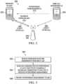
- FIG. 4is an example network 400 for performing a power measurement of a UE at an eUE.
- the network 400includes an eUE 402 and a neighboring UE 404.
- An eNB 405is communicatively coupled to both the eUE 402 and the UE 404.
- the eUE 402receives the enhanced downlink channel 410.
- the UE 404transmits the legacy uplink channel 406.
- the eUE 402determines a power measurement 412 of the legacy uplink channel 406.
- the power measurement 412can be performed at regular intervals by the eUE 402 and reported to the eNB 405.
- the power measurement 412may also be a long-term measurement of the power of the legacy uplink channel 406 over a period of time.
- the eUE 402may determine the power measurement 412 in response to a command from the eNB 405 instructing the eUE 402 to perform the power measurement 412.
- Such measurementsmay be made across the full bandwidth of different sub-carriers.
- the measurementsmay also be specific to a resource block or group of resource blocks.
- the interference signal strength included in the measurementmay be computed over an agreed subset of resource blocks.
- the power measurement 412may indicate noise including interference on the enhanced downlink channel 410 caused by the legacy uplink channel 406.
- the eUE 402may report the power measurement 412 to the eNB 405, allowing the eNB 405 to mitigate the interference in the enhanced downlink channel 410.
- the eNBmay use the measurements to schedule enhanced downlink resources or legacy resources to mitigate interference.
- the eNBmay also use the measurements in scheduling an enhanced downlink transmission mode.
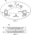
- FIG. 5is a flow chart 500 illustrating an example process for using power measurements of neighboring UEs to avoid interference by uplink and downlink scheduling.
- the eNBreceives a power measurement of the legacy uplink channel that is measured at an eUE.
- the power measuremay include at least one of a sub-carrier, interference measurements of the legacy uplink channel over a plurality of subframes, an identifier of an interfering legacy UE, or other information.
- the eNBmay transmit to a legacy UE using the legacy uplink channel a request to transmit a sounding signal in a specified resource. In these instances, the eUE may then perform the power measurement on the sounding signal the legacy UE transmitted.
- the eNBmay also transmit, to the eUE, a request to measure interference from the sounding signal transmitted by the legacy UE in the specified resource.
- the eNBschedules uplink and downlink transmissions to avoid the interference received at the eUE.
- the eNBschedules downlink transmissions to the eUE in subframes different from subframes assigned to an interfering legacy UE for uplink transmissions in the legacy uplink channel.
- the eNBmay also determine a modulation coding scheme (MCS) for an enhanced downlink channel based on the power measurement of the legacy uplink channel and transmit to the eUE a request use the determined MCS for downlink transmissions.
- MCSmodulation coding scheme
- the downlink transmissionsmay be scheduled by the eNB in accordance with an allocation request from the eUE.
- the eNBcan indicate resource blocks to the UE which can contain an acceptably low amount of (or no) UL transmissions (eNB knows this as it is the scheduler). The UE may then adapt its front end according to this signaled information. These resource blocks may be different than resource blocks containing information destined for the UE.
- an eUEenhances interference cancellation at baseband through the use of pilot signals. For example, an eNB assigns different pilot signals to each associated UE or eUE, and then requests that each UE or eUE send the assigned pilot signal at a certain time. An eUE detects these pilot signals, and determines which of the other UEs are causing interference based on the received pilot signals. In some cases, the eUE reports the received pilot signal and an interference measurement to the eNB, which may determine the identity of the interfering UE.
- the eNBmay, in some cases, take measures to prevent the interference between the UE and the eUE, such as, for example, rescheduling uplink and downlink transmissions to different slots.
- the pilot signalsmay be sounding symbols, such as, for example, Rel'8 sounding symbols.
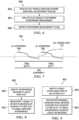
- FIG. 6is a flow chart 600 illustrating an example process for using pilot signals to measure interference by a neighboring UE.
- an eUEreceives pilot signals from one or more additional UEs.
- the eUEanalyzes the pilot signals to determine interference measurements. Each interference measurement is associated with the UE from which the pilot signal is received.
- the eNBassigns different pilot signals to different UEs to enable the eUE or the eNB to determine which of the other UEs on the network is causing interference. For example, if a certain UE is assigned a first pilot signal and an eUE receives that pilot signal, the eUE can correlate the pilot signal to a UE that caused UE interference.
- the eUEblindly decodes uplink transmissions to determine pilot sequences assigned to the one or more interfering legacy UEs.
- the eUEreports the interference measurement to eNB.
- the eUEreports, to the eNB, interference power for uplink transmissions from the one or more interfering legacy UEs.
- FIG. 7is a graphical diagram 700 showing a signal being pre-distorted to mitigate interference detected in a previous slot.
- the diagramshows a subframe 702 including two slots 704a and 704b.
- a legacy uplink channel interferer signal 706is detected at slot 704a.
- a copy 708 of the signal 706is combined with an enhanced downlink signal 710 in slot 704b to pre-distort the enhanced downlink signal 710. In doing this pre-distortion, the interference caused by the legacy uplink channel interferer signal 706 may be substantially canceled.
- FIG. 8is a flow chart 800 illustrating an example process for pre-distorting a transmit signal to mitigate interference detected in a previous slot.
- an eUEidentifies interference received in a first slot.
- the eUEpre-distorts a signal to be sent in a second slot adjacent to the first slot to cancel the identified interference.
- the signalmay comprise at least one of an uplink signal, a downlink signal, or other types of signals.
- the interferencemay be caused by both the uplink transmissions of the legacy UEs and a transmitter of the eUE.
- pre-distorting the signalincludes adding an inverse of the identified interference to the signal in order to cancel the interference.
- FIG. 9is a flow chart 900 illustrating an example process for pre-distorting a received enhanced downlink signal to mitigate interference caused by a legacy uplink channel.
- a legacy uplink signal sent by an eUEis identified in a first slot.
- an enhanced downlink signal received in a second slot adjacent to the first slotis pre-distorted to cancel interference caused by the legacy uplink signal.
- the present implementationsrelate to "Full Duplex" communications - i.e., communications in which the uplink and downlink take place at the same time and at the same band.
- Full duplexmay reuse the same time/frequency/space resource for both uplink downlink transmissions.
- the present implementationsmay enable the use of both Enhanced UEs (eVEs) capable of full duplex operation as well as existing/legacy UEs with existing networks without affecting operation of the legacy UEs.
- eVEsEnhanced UEs
- the present implementationsmay include (1) means for adapting the receiver bandwidth dynamically to exactly cover frequencies used by the desired signal; 2) means for using Rel 8 or other sounding signals and information contained in new measurements; 3) means for reuse of Rel 8 or other sounding signals as a means of aiding an interference cancellation mechanism, as well as an enhanced UE pilot sequence; and 4) means for repeating the interferer signal from an earlier slot for the purposes of reproducing this pattern for explicit interference cancellation.
- legacy uplink of neighboring UEsmay cause interference to new enhanced UE downlink transmissions, i.e., legacy UEs may cause interference for full duplex enabled UEs.
- the present implementationsprovide a number of solutions to alleviate the effects of the interference.
- an eUE enabled solutionmay be provided.
- the eUEmay include a modified front-end to reject frequency resources that contain interference.
- the eUEmay analyze received transmissions and choose to use resources (from among the resources assigned by the eNB) that have the lowest interference levels.
- a method of reducing interference from a legacy User Equipment (UE) in a full-duplex enabled Enhanced User Equipment (eUE)may be provided.
- the methodmay include (1) receiving sub-carrier/Resource Block (RB) assignments from the eNB at the eUE; (2) scanning each sub-carrier/RB assigned for interference at the eUE; and/or (3) dynamically adapting the transceiver at the eUE to only use the carrier frequency/RB that has the least amount of interference from among the sub-carriers/RB's assigned by the eNB.
- the eUE enabled solutionmay include additional, less, or alternate functionality, including functionality discussed elsewhere herein.
- an eUE and eNB interactive solutionmay be provided.
- the eUEmay make certain power measurements associated with the UL (uplink) channel and/or perform measurements of UL sounding signals transmitted by other UEs to measure potential interference. Then, the eUE may send or transmit recommendations to the eNB on resource assignment, such as via a sub-carrier frequency and/or Resource Block.
- a method of reducing interference from a legacy User Equipment (UE) in a full-duplex enabled Enhanced User Equipment (eUE)may be provided.
- the methodmay include receiving at an eNB a power measurement of a legacy uplink channel that is measured at the eUE; and scheduling UL/DL transmissions at the eNB to avoid interference received at the eUE.
- the eUE and eNB interactive solutionmay include additional, less, or alternate functionality, including functionality discussed elsewhere herein.
- an eUE baseband approachmay be provided.
- the eUEmay enhance interference cancellation at the baseband through the use of pilot symbols.
- the methodmay include using pilot signals in the eDL (enhanced downlink) signal to reduce interference at the eUE.
- the eUE baseband approachmay include additional, less, or alternate functionality, including functionality discussed elsewhere herein.
- an eUE analog approachmay be provided.
- the eUE analog approachmay include post-distorting interference received at the eUE in an active slot (slot1) by subtracting interference received in an idle slot (slot0).
- the methodmay include canceling interference received at the eUE in an active slot by subtracting the interference received in an adjacent/preceding idle slot from the signal received in active slot.
- the eUE analog approachmay include additional, less, or alternate functionality, including functionality discussed elsewhere herein.
- a method for managing interferenceincludes receiving, by enhanced user equipment (eUE), an assignment of Resource Blocks (RBs) from an eNodeB (eNB), and the eUE is configured to receive full-duplex transmissions. For each assigned RB, interference caused by uplink transmissions from one or more legacy UEs is measured. The measured interference is reported to the eNB.
- eUEenhanced user equipment
- RBsResource Blocks
- eNBeNodeB
- a method of reducing interferenceincludes receiving, from an eUE, a power measurement of a legacy uplink channel measured at the eUE, and the eUE is configured to receive full-duplex transmissions. Downlink transmissions to the eUE are scheduled, at the eNB, to avoid interference from the legacy uplink channel.
- a method for mitigating interferenceincludes assigning, by an eNB, an eUE a specific pilot sequence different from pilot sequences assigned to one or more interfering legacy UEs, and the eUE is configured to receive full-duplex transmissions.
- the specific pilot sequenceis used in an enhanced downlink (eDL) to the eUE, and the eDL includes full-duplex transmissions.
- a method of mitigating interferenceincludes determining, by the eUE, interference from uplink transmissions of legacy UEs during a first slot when the eUE is inactive, and the eUE is configured to receive full-duplex transmissions.
- a signal in a second slotis pre-distorted to reduce the determined interference in the signal.
Landscapes
- Engineering & Computer Science (AREA)
- Signal Processing (AREA)
- Computer Networks & Wireless Communication (AREA)
- Quality & Reliability (AREA)
- Mobile Radio Communication Systems (AREA)
Description
- The present disclosure pertains to mitigating interference in full duplex communication in wireless communications networks, such as Long-Term Evolution (LTE) networks.
- Communication networks include wired and wireless networks. Example wired networks include the Public Switched Telephone Network (PSTN) and Ethernet local area networks. Example wireless networks include licensed cellular networks, as well as unlicensed wireless networks that connect to wired networks. Calls and other communications may be connected across wired and wireless networks.
- Wireless communication networks include networks utilizing various networking technologies, such as LTE, Code Division Multiple Access (CDMA), Global System for Mobile communication (GSM), 802.11 WiFi, or other technologies. Techniques for performing full duplex communication in these networks may introduce interference between devices communicating with a base station at the same time or at the same frequency as another device.
US 2013/0121186 A1 is directed to data transmission on the uplink with interference mitigation. InUS 2013/0121186 , a given cell identifies interfering UEs which while communicating with neighbor cells cause high interference to the cell. The cell estimates the interference due to the interfering UEs on resources based on which interfering UEs are scheduled for uplink data transmission by the neighbor cells as defined by pre-scheduling information provided by such neighbor cells, and thus schedules its UEs so as to mitigate the interference from the interfering UEs.US 2011/0195704 A1 is directed to a communication system for performing an uplink communication and a downlink communication using an overlapping radio resource. At a downlink terminal, a communication method to perform a downlink communication with a base station includes receiving a reference signal from at least one uplink terminal, and measuring an interference channel formed between the at least one uplink terminal and the downlink terminal based on the reference signal. The method further includes transmitting, to the base station, information regarding the measured interference channel so that the base station selects, from a plurality of terminals, at least one uplink terminal to perform an uplink communication and the downlink terminal to perform the downlink communication. The method further includes receiving, from the base station, control information including information regarding a radio resource for the downlink terminal, and performing the downlink communication with the base station using the radio resource for the downlink terminal, wherein a radio resource for the at least one uplink terminal at least partially overlaps the radio resource for the downlink terminal in both time and frequency. Another example is known fromWO 2009/063001 .FIG. 1 is an example mobile communication system for mitigating interference in full duplex communication in wireless communications networks.FIG. 2 is an example network for detecting and managing user equipment (UE) interference.FIG. 3 is a flow chart illustrating an example process for interference mitigation.FIG. 4 is an example network for performing power measurements of UEs.FIG. 5 is a flow chart illustrating an example process for avoiding UE interference by uplink and downlink scheduling.FIG. 6 is a flow chart illustrating an example process for using pilot signals to measure interference by a neighboring UE.FIG. 7 is a graphical diagram illustrating pre-distorting a signal to mitigate interference.FIG. 8 is a flow chart illustrating an example process for pre-distorting a transmit signal to mitigate interference detected in a previous slot.FIG. 9 is a flow chart illustrating an example process for pre-distorting a downlink signal to mitigate interference from an uplink channel.- Like reference symbols in the various drawings indicate like elements.
- Aspects of the present disclosure pertain to systems, methods, and apparatuses that mitigate interference in full duplex communication in wireless communications networks such as Long-Term Evolution (LTE) networks. Various methods for improving user equipment (UE)-to-evolved Node B (eNB) communication link performance in an enhanced full duplex cellular communication system are described.
- According to one aspect of the present disclosure, there is provided a method an enhance User Equipment, eUE, of facilitating mitigation of interference, according to
claim 1 of the appended claims. - According to another aspect of the present disclosure, there is provide there is provided an enhance User Equipment, eUE, for mitigating interference, according to claim 2 of the appended claims.
- In enhanced full-duplex communication systems, both uplink and downlink may use the same frequency. By using information from other interfering UEs within the same cell, co-channel interference may be estimated and reduced, which can improve channel quality measures (eg: Channel Quality Indicator (CQI), signal-to-noise ratio (SNR), Received Signal Strength Indication (RSSI) and Received Reference Signal Quality (RSRQ)) of a transmitted signal. Also the channel quality measurement computed by the eUE can be used by the eNB for additional scheduling purposes including assigning modulation coding, transmit power and transmission mode selection such as single layer MIMO, multi-layer MIMO and transmit diversity.
- For the purposes of the present disclosure, "user equipment" (UE) refers to any device involved in mobile communication with an eNB that is communicating via standard half-duplex communication techniques. "Enhanced user equipment" (eUE) refers to any device communicating using enhanced full duplex communication techniques,i.e., using the same time and frequency resources for both uplink and downlink signals. A UE may communicate with the transmission mode selection such as single layer MIMO, multi-layer MIMO and transmit diversity.
- For the purposes of the present disclosure, "user equipment" (UE) refers to any device involved in mobile communication with an eNB that is communicating via standard half-duplex communication techniques. "Enhanced user equipment" (eUE) refers to any device communicating using enhanced full duplex communication techniques,i.e., using the same time and frequency resources for both uplink and downlink signals. A UE may communicate with the eNB over various legacy communication channels, such as, for example, a legacy uplink channel, or a legacy downlink channel. An eUE may communicate with the eNB over various enhanced communication channels, such as, for example, an enhanced uplink channel, or an enhanced downlink channel. In some cases, the enhanced uplink channel may be configured to be transmitted using the same time and frequency resources as a legacy downlink channel. Further, the enhanced downlink channel may be configured to be transmitted using the same time and frequency as a legacy uplink channel. Stated another way, full duplex communication may reuse the same time/frequency/space resource for both uplink and downlink transmissions.
- The present disclosure describes various techniques to address interference as a result of UEs and eUEs using the same resources as described above. The techniques address various situations related to such communication, such as a situation where the full bandwidth of an interferer may be received while only a fraction of the bandwidth is used by the desired signal. Further, full duplex operation may mean that traditional measurements reported by the UE to the eNB are not applicable. Therefore, new measurement techniques for efficient operation are described herein. The present disclosure also provides various mechanisms for providing (e.g., to the eNB) ancillary information for performing interference mitigation. Interference cancellation techniques that may be performed at the radio frequency level, such as pre-distorting a transmitted or received signal, are also described.
- In some implementations, the described techniques include adapting receiver bandwidth dynamically to cover frequencies used by a desired signal. The techniques also include using pilot signals (e.g., Rel'8 formatted signals) for identifying interferers, and reporting that information to the eNB in new measurements. Enhanced UE pilot sequences are also described that may be used for interference identification and mitigation. Repeating an interferer signal from an earlier slot for explicit interference cancellation is also described.
- The techniques of the present disclosure may present several possible advantages. eUEs capable of full duplex operation may be utilized in the presence of legacy UEs in existing networks either without affecting operation of legacy UEs or mitigating the impact on legacy UEs by utilizing the techniques of the present disclosure for interference mitigation. Reducing disruption of existing services may lead to reduced cost for the network owner and may simplify transition to full duplex communication techniques. Another advantage includes extending bandwidth for UL and DL, which may improve the rates and potentially the signal quality.
FIG. 1 is an examplemobile communication system 100 for mitigating UE-to-eUE interference. Themobile communication system 100 shown inFIG. 1 may include one or more network nodes (e.g., 112a and 112b). It will be understood that the network node may take several forms in a mobile communication system, such as (but not limited to) an evolved Node B (eNB), a base station, a Node B, a wireless access point, a radio network controller, a base transceiver station, a layer two relay node, a layer three relay node, a femto cell, home evolved Node B (HeNB), a home Node B (HNB), a base station controller, or other network node that includes radio resource control. In the long term evolution (LTE) example ofFIG. 1 , the network nodes are shown as evolved Node Bs (eNBs) 112a and 112b. The examplemobile communication system 100 ofFIG. 1 may include one or moreradio access networks 110, core networks (CNs) 120, andexternal networks 130. In certain implementations, theradio access networks 110 may be evolved- UMTS terrestrial radio access networks (E-UTRAN). In addition, in certain instances, core networks (CNs) 120 may be evolved packet cores (EPCs). Further, there may be one or more mobileelectronic devices mobile communication system 100. In some implementations, 2G/3G systems 140, e.g., Global System for Mobile communication (GSM), Interim Standard 95 (IS-95), IEEE Standards (e.g., WiFi), Universal Mobile Telecommunications System (UMTS) and CDMA2000 (Code Division Multiple Access) may also be integrated into themobile communication system 100.- In the example LTE system shown in
FIG. 1 , theradio access network 110 includeseNB 112a andeNB 112b.Cell 114a is the service area ofeNB 112a, andCell 114b is the service area ofeNB 112b. In this example,eUE 102 andUE 104 operate inCell 114a and are served byeNB 112a. TheeUE 102 andUE 104 may be any electronic device used by an end-user to communicate, for example, within themobile communication system 100. TheeUE 102 andUE 104 may transmit voice data, video data, user data, application data, multimedia data, text, web content or any other content. - This disclosure describes several ways that interference from legacy communication channels may be measured and managed in a full duplex wireless communication system. For the purposes of the present disclosure, full duplex communication is defined as uplink and downlink transmissions between an eUE, such as
eUE 102, and an eNB, such aseNB 112a, occurring or being capable of occurring at the same time and on the same frequency resources. - In one example implementation, the
eUE 102 may detect interference from the neighboringUE 104 and report the interference to the associatedeNB 112a. TheeUE 102 may first receive resource block assignments from theeNB 112a. TheeUE 102 may then scan the assigned resource block for interference by dynamically moving an eUE transceiver to each resource block to produce an interference measurement. TheeUE 102 may then report the interference measurement to theeNB 112a. - In some implementations, the
eUE 102 may receive pilot signals from one or more additional UEs, such as theUE 104. TheeUE 102 may analyze the pilot signals to determine an interference measurement. TheeUE 102 may then report the interference measurement to theeNB 112a. - In some cases, the
eUE 102 may identify interference received in a first slot. TheeUE 102 may then pre-distort a signal to be sent in a second slot adjacent to the first slot to cancel the identified interference. - In another example, the
eUE 102 may identify a legacy uplink signal sent by theeUE 102 in a first slot. TheeUE 102 may then pre-distort an enhanced downlink signal received in a second slot adjacent to the first slot to cancel interference caused by the identified legacy uplink signal. - In general, the
eUE 102 orUE 104 may be referred to as mobile electronic device, user device, mobile station, subscriber station, portable electronic device, mobile communications device, wireless modem, or wireless terminal. Examples of a UE or eUE (e.g.,eUE 102 or UE 104) may include a cellular phone, personal data assistant (PDA), smart phone, laptop, tablet personal computer (PC), pager, portable computer, portable gaming device, wearable electronic device, or other mobile communications device having components for communicating voice or data via a mobile communication network. - Other examples of an eUE or UE include, but are not limited to, a television, a remote controller, a set-top box, a computer monitor, a computer (including a tablet, a desktop computer, a handheld or laptop computer, a netbook computer), a microwave, a refrigerator, a stereo system, a cassette recorder or player, a DVD player or recorder, a CD player or recorder, a VCR, an MP3 player, a radio, a camcorder, a camera, a digital camera, a portable memory chip, a washer, a dryer, a washer/dryer, a copier, a facsimile machine, a scanner, a multi-functional peripheral device, a wristwatch, a clock, and a game device, etc. The
eUE 102 orUE 104 may include a device and a removable memory module, such as a Universal Integrated Circuit Card (UICC) that includes a Subscriber Identity Module (SIM) application, a Universal Subscriber Identity Module (USIM) application, or a Removable User Identity Module (R-UIM) application. Alternatively, theeUE 102 orUE 104 may include the device without such a module. The terms "UE" or "eUE" can also refer to any hardware or software component that can terminate a communication session for a user. In addition, the terms "user equipment," "UE," "user equipment device," "user agent," "UA," "user device," and "mobile device" can be used synonymously herein. - A radio access network is part of a mobile communication system which implements a radio access technology, such as UMTS, CDMA2000 and 3GPP LTE. For example, the radio access network (RAN) 110 included in an LTE telecommunications system is called an EUTRAN. The EUTRAN can be located between the UEs and core network 120 (e.g., an evolved packet core, EPC). The EUTRAN includes at least one eNB. The eNB can be a radio base station that may control all or at least some radio related functions in a fixed part of the system. The at least one eNB can provide a radio interface within their coverage area or a cell for the UEs to communicate. The eNBs may be distributed throughout the cellular network to provide a wide area of coverage. The eNBs directly communicate with one or more UEs, eUEs, other eNBs, and the core network.
- The
eNBs eUE 102, andUE 104 and may relay signals between the radio connection and the connectivity towards thecore network 120. In certain implementations, the EPC may be the main component of acore network 120. Thecore network 120 may include a backbone network, which may be a central part of themobile communication system 100. Thecore network 120 may include other components, such as (but not limited to) a mobility management entity (MME), a serving gateway (SGW), or a packet data network gateway (PGW). The MME may be the main control element in thecore network 120 responsible for the functionalities comprising the control plane functions related to subscriber and session management. The SGW can serve as a local mobility anchor, such that the packets are routed through this point for intra radio access network 110 (e.g., intra-EUTRAN) mobility and mobility withother legacy 2G/3G systems 140. The SGW functions may include the user plane tunnel management and switching. The PGW may provide connectivity to the services domain comprisingexternal networks 130, such as the IP networks. TheeUE 102,UE 104, radio access network 110 (e.g., EUTRAN), and core network 120 (e.g., EPC) are sometimes referred to together as the evolved packet system (EPS). - In some implementations, the
eNBs eNB 112a may then schedule uplink and downlink transmissions to avoid interference received at theeUE 102. - The
eNBs UE 104. The specific pilot sequence is then used in an enhanced downlink channel to theeUE 102. - Though described in terms of
FIG. 1 , the present disclosure is not limited to such an LTE environment. FIG. 2 is a schematic illustrating anexample network 200 for detecting and managing interference by aUE 204 at aneUE 202. As shown, theeUE 202 and theeUE 204 are associated with aneNB 205. Though, theeUE 204 may be in a different cell without departing from the scope of the disclosure. TheeUE 202 is communicatively coupled to theeNB 205 by alegacy uplink channel 208 and anenhanced downlink channel 210.UE 204 is communicatively coupled to theeNB 205 using alegacy uplink channel 206.Legacy uplink channel 206 interferes with theenhanced downlink channel 210 of theeUE 202, which is detected by the eUE asinterference 212. Note that the enhanced downlink does not cause interference to neighboring UEs reception in the same cell and, as a result, is compatible with legacy UEs using legacy uplink channels.- In some implementations, the
eUE 202 may detect theinterference 212 and report interference measurements to theeNB 205. TheeNB 205 may, in turn, perform scheduling of the uplink and downlink communications of theeUE 202 andUE 204 to mitigate theinterference 212. For example,eUE 202 may be scheduled on a predefined resource by theeNB 205. TheeUE 202 may experience the highest interference if full bandwidth is used for thelegacy uplink channel 206 by theUE 204. TheeNB 205 can assigns sub-carriers or resource blocks to theeUE 202 that will not be affected or will be affected less by interference caused by theUE 204. FIG. 3 is aflow chart 300 illustrating an example process for interference mitigation at an eUE. Atstep 302, an eUE receives resource block assignments from an eNB. Atstep 304, the eUE scans each assigned resource block for interference by dynamically moving an eUE transceiver through each resource block to produce interference measurements. For example, the eUE may measure interference by scanning each subcarrier in each of the assigned resource blocks to determine interference from uplink transmissions from the one or more legacy UEs. In some cases, the interference measurements may include a request to communicate using a subset of the assigned resource blocks or specified sub-carriers in the assigned resource blocks. The interference measurement may also include a power measurement, a pilot signal, a sounding sequence, or other measurements or signals.- At
step 306, the eUE reports the measurement to the eNB. In some implementations, the eUE may transmit an indication to the eNB that a subset of the assigned resource blocks or specified sub-carriers in the assigned resource blocks are selected for communication. The eUE may then communicate with the eNB using the subset or the specified sub-carriers. In some instances, the eUE may report carrier frequencies and interference power for uplink transmissions receive a different assignment of resource blocks in response from the eNB. FIG. 4 is anexample network 400 for performing a power measurement of a UE at an eUE. Thenetwork 400 includes aneUE 402 and a neighboringUE 404. AneNB 405 is communicatively coupled to both theeUE 402 and theUE 404. TheeUE 402 receives the enhanceddownlink channel 410. TheUE 404 transmits thelegacy uplink channel 406.- As shown, the
eUE 402 determines apower measurement 412 of thelegacy uplink channel 406. In some implementations, thepower measurement 412 can be performed at regular intervals by theeUE 402 and reported to theeNB 405. Thepower measurement 412 may also be a long-term measurement of the power of thelegacy uplink channel 406 over a period of time. In some cases, theeUE 402 may determine thepower measurement 412 in response to a command from theeNB 405 instructing theeUE 402 to perform thepower measurement 412. Such measurements may be made across the full bandwidth of different sub-carriers. The measurements may also be specific to a resource block or group of resource blocks. The interference signal strength included in the measurement may be computed over an agreed subset of resource blocks. In summary, thepower measurement 412 may indicate noise including interference on theenhanced downlink channel 410 caused by thelegacy uplink channel 406. TheeUE 402 may report thepower measurement 412 to theeNB 405, allowing theeNB 405 to mitigate the interference in theenhanced downlink channel 410. For example, the eNB may use the measurements to schedule enhanced downlink resources or legacy resources to mitigate interference. The eNB may also use the measurements in scheduling an enhanced downlink transmission mode. FIG. 5 is aflow chart 500 illustrating an example process for using power measurements of neighboring UEs to avoid interference by uplink and downlink scheduling. Atstep 502, the eNB receives a power measurement of the legacy uplink channel that is measured at an eUE. In some cases, the power measure may include at least one of a sub-carrier, interference measurements of the legacy uplink channel over a plurality of subframes, an identifier of an interfering legacy UE, or other information. In some instances, the eNB may transmit to a legacy UE using the legacy uplink channel a request to transmit a sounding signal in a specified resource. In these instances, the eUE may then perform the power measurement on the sounding signal the legacy UE transmitted. The eNB may also transmit, to the eUE, a request to measure interference from the sounding signal transmitted by the legacy UE in the specified resource.- At
step 504, the eNB schedules uplink and downlink transmissions to avoid the interference received at the eUE. In some implementations, the eNB schedules downlink transmissions to the eUE in subframes different from subframes assigned to an interfering legacy UE for uplink transmissions in the legacy uplink channel. The eNB may also determine a modulation coding scheme (MCS) for an enhanced downlink channel based on the power measurement of the legacy uplink channel and transmit to the eUE a request use the determined MCS for downlink transmissions. In some cases, the downlink transmissions may be scheduled by the eNB in accordance with an allocation request from the eUE. In some implementations, the eNB can indicate resource blocks to the UE which can contain an acceptably low amount of (or no) UL transmissions (eNB knows this as it is the scheduler). The UE may then adapt its front end according to this signaled information. These resource blocks may be different than resource blocks containing information destined for the UE. - In some implementations, an eUE enhances interference cancellation at baseband through the use of pilot signals. For example, an eNB assigns different pilot signals to each associated UE or eUE, and then requests that each UE or eUE send the assigned pilot signal at a certain time. An eUE detects these pilot signals, and determines which of the other UEs are causing interference based on the received pilot signals. In some cases, the eUE reports the received pilot signal and an interference measurement to the eNB, which may determine the identity of the interfering UE. Once the eNB determines the UE that is causing interference, the eNB may, in some cases, take measures to prevent the interference between the UE and the eUE, such as, for example, rescheduling uplink and downlink transmissions to different slots. In some implementations, the pilot signals may be sounding symbols, such as, for example, Rel'8 sounding symbols.
FIG. 6 is aflow chart 600 illustrating an example process for using pilot signals to measure interference by a neighboring UE. Atstep 602, an eUE receives pilot signals from one or more additional UEs. Atstep 604, the eUE analyzes the pilot signals to determine interference measurements. Each interference measurement is associated with the UE from which the pilot signal is received. The eNB assigns different pilot signals to different UEs to enable the eUE or the eNB to determine which of the other UEs on the network is causing interference. For example, if a certain UE is assigned a first pilot signal and an eUE receives that pilot signal, the eUE can correlate the pilot signal to a UE that caused UE interference. The eUE blindly decodes uplink transmissions to determine pilot sequences assigned to the one or more interfering legacy UEs.- At
step 606, the eUE reports the interference measurement to eNB. In some cases, the eUE reports, to the eNB, interference power for uplink transmissions from the one or more interfering legacy UEs. FIG. 7 is a graphical diagram 700 showing a signal being pre-distorted to mitigate interference detected in a previous slot. The diagram shows asubframe 702 including twoslots channel interferer signal 706 is detected atslot 704a. Acopy 708 of thesignal 706 is combined with an enhanced downlink signal 710 inslot 704b to pre-distort the enhanced downlink signal 710. In doing this pre-distortion, the interference caused by the legacy uplinkchannel interferer signal 706 may be substantially canceled.FIG. 8 is aflow chart 800 illustrating an example process for pre-distorting a transmit signal to mitigate interference detected in a previous slot. Atstep 802, an eUE identifies interference received in a first slot. Atstep 804, the eUE pre-distorts a signal to be sent in a second slot adjacent to the first slot to cancel the identified interference. The signal may comprise at least one of an uplink signal, a downlink signal, or other types of signals. In some cases, if the signal is a downlink signal, the interference may be caused by both the uplink transmissions of the legacy UEs and a transmitter of the eUE. In some implementations, pre-distorting the signal includes adding an inverse of the identified interference to the signal in order to cancel the interference.FIG. 9 is aflow chart 900 illustrating an example process for pre-distorting a received enhanced downlink signal to mitigate interference caused by a legacy uplink channel. Atstep 902, a legacy uplink signal sent by an eUE is identified in a first slot. Atstep 904, an enhanced downlink signal received in a second slot adjacent to the first slot is pre-distorted to cancel interference caused by the legacy uplink signal.- As noted above, the present implementations relate to "Full Duplex" communications -i.e., communications in which the uplink and downlink take place at the same time and at the same band. Full duplex may reuse the same time/frequency/space resource for both uplink downlink transmissions. The present implementations may enable the use of both Enhanced UEs (eVEs) capable of full duplex operation as well as existing/legacy UEs with existing networks without affecting operation of the legacy UEs.
- The present implementations may include (1) means for adapting the receiver bandwidth dynamically to exactly cover frequencies used by the desired signal; 2) means for using Rel 8 or other sounding signals and information contained in new measurements; 3) means for reuse of Rel 8 or other sounding signals as a means of aiding an interference cancellation mechanism, as well as an enhanced UE pilot sequence; and 4) means for repeating the interferer signal from an earlier slot for the purposes of reproducing this pattern for explicit interference cancellation.
- In some aspects, legacy uplink of neighboring UEs may cause interference to new enhanced UE downlink transmissions,i.e., legacy UEs may cause interference for full duplex enabled UEs. The present implementations provide a number of solutions to alleviate the effects of the interference.
- In some implementations, an eUE enabled solution may be provided. The eUE may include a modified front-end to reject frequency resources that contain interference. The eUE may analyze received transmissions and choose to use resources (from among the resources assigned by the eNB) that have the lowest interference levels.
- For example, a method of reducing interference from a legacy User Equipment (UE) in a full-duplex enabled Enhanced User Equipment (eUE) may be provided. The method may include (1) receiving sub-carrier/Resource Block (RB) assignments from the eNB at the eUE; (2) scanning each sub-carrier/RB assigned for interference at the eUE; and/or (3) dynamically adapting the transceiver at the eUE to only use the carrier frequency/RB that has the least amount of interference from among the sub-carriers/RB's assigned by the eNB. The eUE enabled solution may include additional, less, or alternate functionality, including functionality discussed elsewhere herein.
- In another implementation, an eUE and eNB interactive solution may be provided. The eUE may make certain power measurements associated with the UL (uplink) channel and/or perform measurements of UL sounding signals transmitted by other UEs to measure potential interference. Then, the eUE may send or transmit recommendations to the eNB on resource assignment, such as via a sub-carrier frequency and/or Resource Block.
- For example, a method of reducing interference from a legacy User Equipment (UE) in a full-duplex enabled Enhanced User Equipment (eUE) may be provided. The method may include receiving at an eNB a power measurement of a legacy uplink channel that is measured at the eUE; and scheduling UL/DL transmissions at the eNB to avoid interference received at the eUE. The eUE and eNB interactive solution may include additional, less, or alternate functionality, including functionality discussed elsewhere herein.
- In another implementation, an eUE baseband approach may be provided. The eUE may enhance interference cancellation at the baseband through the use of pilot symbols. For example, the method may include using pilot signals in the eDL (enhanced downlink) signal to reduce interference at the eUE. The eUE baseband approach may include additional, less, or alternate functionality, including functionality discussed elsewhere herein.
- In another implementation, an eUE analog approach may be provided. The eUE analog approach may include post-distorting interference received at the eUE in an active slot (slot1) by subtracting interference received in an idle slot (slot0). In other words, the method may include canceling interference received at the eUE in an active slot by subtracting the interference received in an adjacent/preceding idle slot from the signal received in active slot. The eUE analog approach may include additional, less, or alternate functionality, including functionality discussed elsewhere herein.
- In some implementations, a method for managing interference includes receiving, by enhanced user equipment (eUE), an assignment of Resource Blocks (RBs) from an eNodeB (eNB), and the eUE is configured to receive full-duplex transmissions. For each assigned RB, interference caused by uplink transmissions from one or more legacy UEs is measured. The measured interference is reported to the eNB.
- In some implementations, a method of reducing interference includes receiving, from an eUE, a power measurement of a legacy uplink channel measured at the eUE, and the eUE is configured to receive full-duplex transmissions. Downlink transmissions to the eUE are scheduled, at the eNB, to avoid interference from the legacy uplink channel.
- In some implementations, a method for mitigating interference includes assigning, by an eNB, an eUE a specific pilot sequence different from pilot sequences assigned to one or more interfering legacy UEs, and the eUE is configured to receive full-duplex transmissions. The specific pilot sequence is used in an enhanced downlink (eDL) to the eUE, and the eDL includes full-duplex transmissions.
- In some implementations, a method of mitigating interference includes determining, by the eUE, interference from uplink transmissions of legacy UEs during a first slot when the eUE is inactive, and the eUE is configured to receive full-duplex transmissions. A signal in a second slot is pre-distorted to reduce the determined interference in the signal.
- While several implementations have been provided in the present disclosure, it should be understood that the disclosed systems and methods may be embodied in many other specific forms without departing from the scope of the present disclosure. The present examples are to be considered as illustrative and not restrictive, and the intention is not to be limited to the details given herein. For example, the various elements or components may be combined or integrated in another system or certain features may be omitted, or not implemented.
- Similarly, while operations are depicted in the drawings in a particular order, this should not be understood as requiring that such operations be performed in the particular order shown or in sequential order, or that all illustrated operations be performed, to achieve desirable results. In certain circumstances, multitasking and parallel processing may be advantageous. Moreover, the separation of various system components in the implementations described above should not be understood as requiring such separation in all implementations, and it should be understood that the described program components and systems can generally be integrated together in a signal software product or packaged into multiple software products.
Claims (2)
- A method carried out at an enhanced user equipment, abbreviated as eUE, (202) for mitigating interference detected at the eUE, in a mobile communication system (100) including an enhanced Node B, abbreviated as eNB, (205) and, configured for communication therewith, the eUE (202) and one or more interfering legacy user equipments, abbreviated as UEs, (204), wherein the eUE (202) operates in an enhanced full-duplex mode with the eNB (205), the enhanced full-duplex mode including the eUE (202) using a same time and frequency resource for uplink and downlink signals with the eNB (205), and wherein the one or more interfering legacy UEs (204) communicate with the eNB (205) via standard half-duplex communication techniquescharacterized in the method comprising, at the eUE (202):receiving (602) legacy uplink transmissions including pilot sequences from the one or more interfering legacy UEs (204), wherein the pilot sequences for the one or more legacy UEs (204) are assigned by the eNB (205) and are different from a specific pilot sequence assigned to the eUE (202), and different pilot sequences are assigned to different legacy UEs,determining (604) interference measurements associated with the pilot sequences received from the one or more legacy UEs (204), wherein the determination (604) comprises blindly decoding said legacy uplink transmissions to determine pilot sequences assigned to the one or more interfering legacy UEs (204); andreporting (606) the interference measurements to the eNB (205).
- An enhanced user equipment, abbreviated as eUE, (202) for mitigating interference detected by the eUE, in a mobile communication system (100) including an enhanced Node B, abbreviated as eNB, (205) and, configured for communication therewith, the eUE (202) and one or more interfering legacy user equipments, abbreviated as UEs (204), wherein the eUE (202) operates in an enhanced full-duplex mode with the eNB (205), the enhanced full-duplex mode including the eUE (202) using a same time and frequency resource for uplink and downlink signals with the eNB (205), and wherein the one or more interfering legacy UEs (204) communicate with the eNB (205) via standard half-duplex communication techniquescharacterized in the eUE comprising:
one or more processors configured to:receive (602) legacy uplink transmissions (206) including pilot sequences from the one or more interfering legacy UEs (204), wherein the pilot sequences for the one or more legacy UEs (204) are assigned by the eNB (205) and are different from a specific pilot sequence assigned to the eUE (202), and different pilot sequences are assigned to different legacy UEs,determine (604) interference measurements associated with the pilot sequences received from the one or more legacy UEs (204), wherein the determination (604) blindly decode said legacy uplink transmissions to determine pilot sequences assigned to the one or more interfering legacy UEs (204); andreport (606) the interference measurements to the eNB (205).
Applications Claiming Priority (1)
| Application Number | Priority Date | Filing Date | Title |
|---|---|---|---|
| US14/027,004US10110264B2 (en) | 2013-09-13 | 2013-09-13 | Full duplex resource reuse enablement |
Publications (3)
| Publication Number | Publication Date |
|---|---|
| EP2858444A2 EP2858444A2 (en) | 2015-04-08 |
| EP2858444A3 EP2858444A3 (en) | 2015-07-08 |
| EP2858444B1true EP2858444B1 (en) | 2023-03-08 |
Family
ID=51355462
Family Applications (1)
| Application Number | Title | Priority Date | Filing Date |
|---|---|---|---|
| EP14181140.6AActiveEP2858444B1 (en) | 2013-09-13 | 2014-08-15 | Full duplex resource reuse enablement |
Country Status (3)
| Country | Link |
|---|---|
| US (1) | US10110264B2 (en) |
| EP (1) | EP2858444B1 (en) |
| CA (1) | CA2863008C (en) |
Families Citing this family (3)
| Publication number | Priority date | Publication date | Assignee | Title |
|---|---|---|---|---|
| US20170141867A1 (en)* | 2014-05-06 | 2017-05-18 | Intel Corporation | Interference cancellation for signals having the same radio-frequency carrier and transmitted at the same time |
| KR102287526B1 (en)* | 2015-05-14 | 2021-08-06 | 에스케이텔레콤 주식회사 | Base station, control method and system for full duplex transmission |
| US10757712B2 (en)* | 2016-02-22 | 2020-08-25 | Microsoft Technology Licensing, Llc | Restricted frequency band interference cancellation |
Citations (2)
| Publication number | Priority date | Publication date | Assignee | Title |
|---|---|---|---|---|
| WO2009063001A2 (en)* | 2007-11-16 | 2009-05-22 | Telefonaktiebolaget Lm Ericsson (Publ) | Adaptive scheduling for half-duplex wireless terminals |
| US20110195704A1 (en)* | 2010-02-09 | 2011-08-11 | Choi Hyun Ho | Communication system of performing uplink communication and downlink communication using overlapping radio resource |
Family Cites Families (22)
| Publication number | Priority date | Publication date | Assignee | Title |
|---|---|---|---|---|
| US6674808B1 (en)* | 1999-12-28 | 2004-01-06 | General Dynamics Decision Systems, Inc. | Post-amplifier filter rejection equalization |
| DE60330405D1 (en)* | 2003-10-07 | 2010-01-14 | Ericsson Telefon Ab L M | METHOD AND SYSTEM FOR TRANSMISSION CONTROL |
| US8068465B2 (en)* | 2006-10-31 | 2011-11-29 | Motorola Mobility, Inc. | Wireless multicast broadcast service methods and apparatus |
| US8538492B2 (en)* | 2007-08-31 | 2013-09-17 | Centurylink Intellectual Property Llc | System and method for localized noise cancellation |
| US8863235B2 (en) | 2008-05-13 | 2014-10-14 | At&T Mobility Ii Llc | Time-dependent white list generation |
| US9072060B2 (en) | 2008-06-03 | 2015-06-30 | Nokia Technologies Oy | Method, apparatus and computer program for power control to mitigate interference |
| US20090305715A1 (en) | 2008-06-04 | 2009-12-10 | Motorola, Inc. | Channel quality reporting in a wireless communication system |
| WO2010105210A2 (en)* | 2009-03-12 | 2010-09-16 | Comsys Communication & Signal Processing Ltd. | Vehicle integrated communications system |
| US8817702B2 (en) | 2009-07-22 | 2014-08-26 | Qualcomm Incorporated | Mitigation of interference due to peer-to-peer communication |
| EP2491689A1 (en)* | 2009-10-20 | 2012-08-29 | Telefonaktiebolaget LM Ericsson (publ) | Controllable filter to diagonalize a transmission channel |
| US10651962B2 (en) | 2009-11-02 | 2020-05-12 | Hmd Global Oy | Scheme for multi-cell UL sounding transmission |
| US8521886B2 (en)* | 2011-01-19 | 2013-08-27 | Qualcomm Incorporated | Methods and apparatus for determining and/or using a communications mode |
| US9887728B2 (en)* | 2011-02-03 | 2018-02-06 | The Board Of Trustees Of The Leland Stanford Junior University | Single channel full duplex wireless communications |
| CN102142918B (en) | 2011-03-29 | 2015-04-08 | 电信科学技术研究院 | Method and equipment for processing pilot sequence |
| US9014110B2 (en) | 2011-07-18 | 2015-04-21 | Qualcomm Incorporated | Enabling half-duplex operation |
| US9049730B2 (en) | 2011-11-14 | 2015-06-02 | Qualcomm Incorporated | Uplink data transmission with interference mitigation |
| CN103209415B (en)* | 2012-01-16 | 2017-08-04 | 华为技术有限公司 | Full-duplex interference processing method and device |
| CN103220723B (en)* | 2012-01-18 | 2016-08-10 | 华为技术有限公司 | Wireless communications method and device |
| US20140126532A1 (en)* | 2012-11-05 | 2014-05-08 | Stoke, Inc. | Seamless mobility from 3g network to wifi network |
| WO2014088271A1 (en)* | 2012-12-09 | 2014-06-12 | 엘지전자 주식회사 | Method and device for transmitting and receiving signal in multi-cell cooperative communication system |
| EP2981143B1 (en)* | 2013-04-25 | 2020-07-08 | Huawei Technologies Co., Ltd. | Interference suppression method, related device, and system |
| US9883404B2 (en)* | 2013-06-11 | 2018-01-30 | Qualcomm Incorporated | LTE/LTE—A uplink carrier aggregation using unlicensed spectrum |
- 2013
- 2013-09-13USUS14/027,004patent/US10110264B2/enactiveActive
- 2014
- 2014-08-15EPEP14181140.6Apatent/EP2858444B1/enactiveActive
- 2014-09-11CACA2863008Apatent/CA2863008C/enactiveActive
Patent Citations (2)
| Publication number | Priority date | Publication date | Assignee | Title |
|---|---|---|---|---|
| WO2009063001A2 (en)* | 2007-11-16 | 2009-05-22 | Telefonaktiebolaget Lm Ericsson (Publ) | Adaptive scheduling for half-duplex wireless terminals |
| US20110195704A1 (en)* | 2010-02-09 | 2011-08-11 | Choi Hyun Ho | Communication system of performing uplink communication and downlink communication using overlapping radio resource |
Also Published As
| Publication number | Publication date |
|---|---|
| EP2858444A3 (en) | 2015-07-08 |
| CA2863008A1 (en) | 2015-03-13 |
| US20150078212A1 (en) | 2015-03-19 |
| CA2863008C (en) | 2019-10-15 |
| US10110264B2 (en) | 2018-10-23 |
| EP2858444A2 (en) | 2015-04-08 |
Similar Documents
| Publication | Publication Date | Title |
|---|---|---|
| US10123222B2 (en) | Mitigating interference in full duplex communication | |
| US9271167B2 (en) | Determination of radio link failure with enhanced interference coordination and cancellation | |
| US8442069B2 (en) | System and method to enable uplink control for restricted association networks | |
| JP6006358B2 (en) | System and method for inter-cell interference avoidance in a co-channel network | |
| US9788327B2 (en) | Methods and apparatus for reducing interference in a heterogeneous network | |
| US8593933B2 (en) | Modified spatial diversity schemes for coverage enhancement | |
| US9100868B2 (en) | Channel state information measurement and reporting | |
| US9374253B2 (en) | DM-RS based decoding using CSI-RS-based timing | |
| US9143957B2 (en) | Mitigating cross-device interference | |
| US9356725B2 (en) | Method and apparatus for managing inter-cell interference coordination actions for time-domain partitioned cells | |
| CN103262599B (en) | Method and apparatus for providing interference measurements in a coordinated multipoint transmission environment | |
| JP6092889B2 (en) | Efficient spectrum use in ABS (ALMOSTBLANKSUBFRAMES) | |
| US10244540B2 (en) | Systems and methods for mixed interference management | |
| US9762426B2 (en) | Interference cancellation | |
| US8774092B2 (en) | Enhancing uplink coverage in interference scenarios | |
| US10075879B2 (en) | Methods for detecting interferers for handling interference mitigation | |
| KR20130010128A (en) | Semi-persistent scheduling grants in heterogeneous networks | |
| RU2602275C2 (en) | Communication control device, communication method, terminal communication device and program | |
| US20200022169A1 (en) | Information transmission method, apparatus, and system | |
| EP2858444B1 (en) | Full duplex resource reuse enablement | |
| HK1218483B (en) | Interference management for different wireless communication technologies |
Legal Events
| Date | Code | Title | Description |
|---|---|---|---|
| PUAI | Public reference made under article 153(3) epc to a published international application that has entered the european phase | Free format text:ORIGINAL CODE: 0009012 | |
| 17P | Request for examination filed | Effective date:20140815 | |
| AK | Designated contracting states | Kind code of ref document:A2 Designated state(s):AL AT BE BG CH CY CZ DE DK EE ES FI FR GB GR HR HU IE IS IT LI LT LU LV MC MK MT NL NO PL PT RO RS SE SI SK SM TR | |
| AX | Request for extension of the european patent | Extension state:BA ME | |
| PUAL | Search report despatched | Free format text:ORIGINAL CODE: 0009013 | |
| AK | Designated contracting states | Kind code of ref document:A3 Designated state(s):AL AT BE BG CH CY CZ DE DK EE ES FI FR GB GR HR HU IE IS IT LI LT LU LV MC MK MT NL NO PL PT RO RS SE SI SK SM TR | |
| AX | Request for extension of the european patent | Extension state:BA ME | |
| RIC1 | Information provided on ipc code assigned before grant | Ipc:H04W 72/08 20090101AFI20150602BHEP Ipc:H04W 72/12 20090101ALI20150602BHEP | |
| STAA | Information on the status of an ep patent application or granted ep patent | Free format text:STATUS: EXAMINATION IS IN PROGRESS | |
| 17Q | First examination report despatched | Effective date:20170811 | |
| GRAP | Despatch of communication of intention to grant a patent | Free format text:ORIGINAL CODE: EPIDOSNIGR1 | |
| STAA | Information on the status of an ep patent application or granted ep patent | Free format text:STATUS: GRANT OF PATENT IS INTENDED | |
| INTG | Intention to grant announced | Effective date:20221103 | |
| RIN1 | Information on inventor provided before grant (corrected) | Inventor name:ALI, SHIROOK M Inventor name:BUCKLEY, MICHAEL EOIN | |
| GRAS | Grant fee paid | Free format text:ORIGINAL CODE: EPIDOSNIGR3 | |
| GRAA | (expected) grant | Free format text:ORIGINAL CODE: 0009210 | |
| STAA | Information on the status of an ep patent application or granted ep patent | Free format text:STATUS: THE PATENT HAS BEEN GRANTED | |
| AK | Designated contracting states | Kind code of ref document:B1 Designated state(s):AL AT BE BG CH CY CZ DE DK EE ES FI FR GB GR HR HU IE IS IT LI LT LU LV MC MK MT NL NO PL PT RO RS SE SI SK SM TR | |
| REG | Reference to a national code | Ref country code:GB Ref legal event code:FG4D | |
| REG | Reference to a national code | Ref country code:CH Ref legal event code:EP Ref country code:AT Ref legal event code:REF Ref document number:1553415 Country of ref document:AT Kind code of ref document:T Effective date:20230315 | |
| REG | Reference to a national code | Ref country code:IE Ref legal event code:FG4D | |
| REG | Reference to a national code | Ref country code:DE Ref legal event code:R096 Ref document number:602014086395 Country of ref document:DE | |
| REG | Reference to a national code | Ref country code:LT Ref legal event code:MG9D | |
| REG | Reference to a national code | Ref country code:NL Ref legal event code:MP Effective date:20230308 | |
| PG25 | Lapsed in a contracting state [announced via postgrant information from national office to epo] | Ref country code:RS Free format text:LAPSE BECAUSE OF FAILURE TO SUBMIT A TRANSLATION OF THE DESCRIPTION OR TO PAY THE FEE WITHIN THE PRESCRIBED TIME-LIMIT Effective date:20230308 Ref country code:NO Free format text:LAPSE BECAUSE OF FAILURE TO SUBMIT A TRANSLATION OF THE DESCRIPTION OR TO PAY THE FEE WITHIN THE PRESCRIBED TIME-LIMIT Effective date:20230608 Ref country code:LV Free format text:LAPSE BECAUSE OF FAILURE TO SUBMIT A TRANSLATION OF THE DESCRIPTION OR TO PAY THE FEE WITHIN THE PRESCRIBED TIME-LIMIT Effective date:20230308 Ref country code:LT Free format text:LAPSE BECAUSE OF FAILURE TO SUBMIT A TRANSLATION OF THE DESCRIPTION OR TO PAY THE FEE WITHIN THE PRESCRIBED TIME-LIMIT Effective date:20230308 Ref country code:HR Free format text:LAPSE BECAUSE OF FAILURE TO SUBMIT A TRANSLATION OF THE DESCRIPTION OR TO PAY THE FEE WITHIN THE PRESCRIBED TIME-LIMIT Effective date:20230308 Ref country code:ES Free format text:LAPSE BECAUSE OF FAILURE TO SUBMIT A TRANSLATION OF THE DESCRIPTION OR TO PAY THE FEE WITHIN THE PRESCRIBED TIME-LIMIT Effective date:20230308 | |
| REG | Reference to a national code | Ref country code:AT Ref legal event code:MK05 Ref document number:1553415 Country of ref document:AT Kind code of ref document:T Effective date:20230308 | |
| PG25 | Lapsed in a contracting state [announced via postgrant information from national office to epo] | Ref country code:SE Free format text:LAPSE BECAUSE OF FAILURE TO SUBMIT A TRANSLATION OF THE DESCRIPTION OR TO PAY THE FEE WITHIN THE PRESCRIBED TIME-LIMIT Effective date:20230308 Ref country code:NL Free format text:LAPSE BECAUSE OF FAILURE TO SUBMIT A TRANSLATION OF THE DESCRIPTION OR TO PAY THE FEE WITHIN THE PRESCRIBED TIME-LIMIT Effective date:20230308 Ref country code:GR Free format text:LAPSE BECAUSE OF FAILURE TO SUBMIT A TRANSLATION OF THE DESCRIPTION OR TO PAY THE FEE WITHIN THE PRESCRIBED TIME-LIMIT Effective date:20230609 Ref country code:FI Free format text:LAPSE BECAUSE OF FAILURE TO SUBMIT A TRANSLATION OF THE DESCRIPTION OR TO PAY THE FEE WITHIN THE PRESCRIBED TIME-LIMIT Effective date:20230308 | |
| PG25 | Lapsed in a contracting state [announced via postgrant information from national office to epo] | Ref country code:SM Free format text:LAPSE BECAUSE OF FAILURE TO SUBMIT A TRANSLATION OF THE DESCRIPTION OR TO PAY THE FEE WITHIN THE PRESCRIBED TIME-LIMIT Effective date:20230308 Ref country code:RO Free format text:LAPSE BECAUSE OF FAILURE TO SUBMIT A TRANSLATION OF THE DESCRIPTION OR TO PAY THE FEE WITHIN THE PRESCRIBED TIME-LIMIT Effective date:20230308 Ref country code:PT Free format text:LAPSE BECAUSE OF FAILURE TO SUBMIT A TRANSLATION OF THE DESCRIPTION OR TO PAY THE FEE WITHIN THE PRESCRIBED TIME-LIMIT Effective date:20230710 Ref country code:EE Free format text:LAPSE BECAUSE OF FAILURE TO SUBMIT A TRANSLATION OF THE DESCRIPTION OR TO PAY THE FEE WITHIN THE PRESCRIBED TIME-LIMIT Effective date:20230308 Ref country code:CZ Free format text:LAPSE BECAUSE OF FAILURE TO SUBMIT A TRANSLATION OF THE DESCRIPTION OR TO PAY THE FEE WITHIN THE PRESCRIBED TIME-LIMIT Effective date:20230308 Ref country code:AT Free format text:LAPSE BECAUSE OF FAILURE TO SUBMIT A TRANSLATION OF THE DESCRIPTION OR TO PAY THE FEE WITHIN THE PRESCRIBED TIME-LIMIT Effective date:20230308 | |
| PG25 | Lapsed in a contracting state [announced via postgrant information from national office to epo] | Ref country code:SK Free format text:LAPSE BECAUSE OF FAILURE TO SUBMIT A TRANSLATION OF THE DESCRIPTION OR TO PAY THE FEE WITHIN THE PRESCRIBED TIME-LIMIT Effective date:20230308 Ref country code:PL Free format text:LAPSE BECAUSE OF FAILURE TO SUBMIT A TRANSLATION OF THE DESCRIPTION OR TO PAY THE FEE WITHIN THE PRESCRIBED TIME-LIMIT Effective date:20230308 Ref country code:IS Free format text:LAPSE BECAUSE OF FAILURE TO SUBMIT A TRANSLATION OF THE DESCRIPTION OR TO PAY THE FEE WITHIN THE PRESCRIBED TIME-LIMIT Effective date:20230708 | |
| REG | Reference to a national code | Ref country code:DE Ref legal event code:R097 Ref document number:602014086395 Country of ref document:DE | |
| PLBE | No opposition filed within time limit | Free format text:ORIGINAL CODE: 0009261 | |
| STAA | Information on the status of an ep patent application or granted ep patent | Free format text:STATUS: NO OPPOSITION FILED WITHIN TIME LIMIT | |
| PG25 | Lapsed in a contracting state [announced via postgrant information from national office to epo] | Ref country code:SI Free format text:LAPSE BECAUSE OF FAILURE TO SUBMIT A TRANSLATION OF THE DESCRIPTION OR TO PAY THE FEE WITHIN THE PRESCRIBED TIME-LIMIT Effective date:20230308 Ref country code:DK Free format text:LAPSE BECAUSE OF FAILURE TO SUBMIT A TRANSLATION OF THE DESCRIPTION OR TO PAY THE FEE WITHIN THE PRESCRIBED TIME-LIMIT Effective date:20230308 | |
| 26N | No opposition filed | Effective date:20231211 | |
| PG25 | Lapsed in a contracting state [announced via postgrant information from national office to epo] | Ref country code:MC Free format text:LAPSE BECAUSE OF FAILURE TO SUBMIT A TRANSLATION OF THE DESCRIPTION OR TO PAY THE FEE WITHIN THE PRESCRIBED TIME-LIMIT Effective date:20230308 | |
| REG | Reference to a national code | Ref country code:CH Ref legal event code:PL | |
| PG25 | Lapsed in a contracting state [announced via postgrant information from national office to epo] | Ref country code:MC Free format text:LAPSE BECAUSE OF FAILURE TO SUBMIT A TRANSLATION OF THE DESCRIPTION OR TO PAY THE FEE WITHIN THE PRESCRIBED TIME-LIMIT Effective date:20230308 | |
| PG25 | Lapsed in a contracting state [announced via postgrant information from national office to epo] | Ref country code:LU Free format text:LAPSE BECAUSE OF NON-PAYMENT OF DUE FEES Effective date:20230815 | |
| PG25 | Lapsed in a contracting state [announced via postgrant information from national office to epo] | Ref country code:LU Free format text:LAPSE BECAUSE OF NON-PAYMENT OF DUE FEES Effective date:20230815 Ref country code:CH Free format text:LAPSE BECAUSE OF NON-PAYMENT OF DUE FEES Effective date:20230831 | |
| REG | Reference to a national code | Ref country code:BE Ref legal event code:MM Effective date:20230831 | |
| REG | Reference to a national code | Ref country code:DE Ref legal event code:R081 Ref document number:602014086395 Country of ref document:DE Owner name:MALIKIE INNOVATIONS LTD., IE Free format text:FORMER OWNER: BLACKBERRY LIMITED, WATERLOO, ON, CA | |
| REG | Reference to a national code | Ref country code:IE Ref legal event code:MM4A | |
| PG25 | Lapsed in a contracting state [announced via postgrant information from national office to epo] | Ref country code:IT Free format text:LAPSE BECAUSE OF FAILURE TO SUBMIT A TRANSLATION OF THE DESCRIPTION OR TO PAY THE FEE WITHIN THE PRESCRIBED TIME-LIMIT Effective date:20230308 | |
| PG25 | Lapsed in a contracting state [announced via postgrant information from national office to epo] | Ref country code:IE Free format text:LAPSE BECAUSE OF NON-PAYMENT OF DUE FEES Effective date:20230815 | |
| REG | Reference to a national code | Ref country code:GB Ref legal event code:732E Free format text:REGISTERED BETWEEN 20240620 AND 20240627 | |
| PG25 | Lapsed in a contracting state [announced via postgrant information from national office to epo] | Ref country code:IE Free format text:LAPSE BECAUSE OF NON-PAYMENT OF DUE FEES Effective date:20230815 | |
| PG25 | Lapsed in a contracting state [announced via postgrant information from national office to epo] | Ref country code:BE Free format text:LAPSE BECAUSE OF NON-PAYMENT OF DUE FEES Effective date:20230831 | |
| PGFP | Annual fee paid to national office [announced via postgrant information from national office to epo] | Ref country code:DE Payment date:20240828 Year of fee payment:11 | |
| PGFP | Annual fee paid to national office [announced via postgrant information from national office to epo] | Ref country code:GB Payment date:20240827 Year of fee payment:11 | |
| PGFP | Annual fee paid to national office [announced via postgrant information from national office to epo] | Ref country code:FR Payment date:20240826 Year of fee payment:11 | |
| PG25 | Lapsed in a contracting state [announced via postgrant information from national office to epo] | Ref country code:BG Free format text:LAPSE BECAUSE OF FAILURE TO SUBMIT A TRANSLATION OF THE DESCRIPTION OR TO PAY THE FEE WITHIN THE PRESCRIBED TIME-LIMIT Effective date:20230308 | |
| PG25 | Lapsed in a contracting state [announced via postgrant information from national office to epo] | Ref country code:BG Free format text:LAPSE BECAUSE OF FAILURE TO SUBMIT A TRANSLATION OF THE DESCRIPTION OR TO PAY THE FEE WITHIN THE PRESCRIBED TIME-LIMIT Effective date:20230308 | |
| PG25 | Lapsed in a contracting state [announced via postgrant information from national office to epo] | Ref country code:CY Free format text:LAPSE BECAUSE OF FAILURE TO SUBMIT A TRANSLATION OF THE DESCRIPTION OR TO PAY THE FEE WITHIN THE PRESCRIBED TIME-LIMIT; INVALID AB INITIO Effective date:20140815 | |
| PG25 | Lapsed in a contracting state [announced via postgrant information from national office to epo] | Ref country code:HU Free format text:LAPSE BECAUSE OF FAILURE TO SUBMIT A TRANSLATION OF THE DESCRIPTION OR TO PAY THE FEE WITHIN THE PRESCRIBED TIME-LIMIT; INVALID AB INITIO Effective date:20140815 |