EP2855937B1 - Disc pump with perimeter valve configuration - Google Patents
Disc pump with perimeter valve configurationDownload PDFInfo
- Publication number
- EP2855937B1 EP2855937B1EP13718987.4AEP13718987AEP2855937B1EP 2855937 B1EP2855937 B1EP 2855937B1EP 13718987 AEP13718987 AEP 13718987AEP 2855937 B1EP2855937 B1EP 2855937B1
- Authority
- EP
- European Patent Office
- Prior art keywords
- valve
- isolator
- valve flap
- apertures
- aperture
- Prior art date
- Legal status (The legal status is an assumption and is not a legal conclusion. Google has not performed a legal analysis and makes no representation as to the accuracy of the status listed.)
- Active
Links
Images


Classifications
- F—MECHANICAL ENGINEERING; LIGHTING; HEATING; WEAPONS; BLASTING
- F04—POSITIVE - DISPLACEMENT MACHINES FOR LIQUIDS; PUMPS FOR LIQUIDS OR ELASTIC FLUIDS
- F04B—POSITIVE-DISPLACEMENT MACHINES FOR LIQUIDS; PUMPS
- F04B43/00—Machines, pumps, or pumping installations having flexible working members
- F04B43/02—Machines, pumps, or pumping installations having flexible working members having plate-like flexible members, e.g. diaphragms
- F04B43/028—Machines, pumps, or pumping installations having flexible working members having plate-like flexible members, e.g. diaphragms with in- or outlet valve arranged in the plate-like flexible member
- F—MECHANICAL ENGINEERING; LIGHTING; HEATING; WEAPONS; BLASTING
- F04—POSITIVE - DISPLACEMENT MACHINES FOR LIQUIDS; PUMPS FOR LIQUIDS OR ELASTIC FLUIDS
- F04B—POSITIVE-DISPLACEMENT MACHINES FOR LIQUIDS; PUMPS
- F04B17/00—Pumps characterised by combination with, or adaptation to, specific driving engines or motors
- F04B17/003—Pumps characterised by combination with, or adaptation to, specific driving engines or motors driven by piezoelectric means
- F—MECHANICAL ENGINEERING; LIGHTING; HEATING; WEAPONS; BLASTING
- F04—POSITIVE - DISPLACEMENT MACHINES FOR LIQUIDS; PUMPS FOR LIQUIDS OR ELASTIC FLUIDS
- F04B—POSITIVE-DISPLACEMENT MACHINES FOR LIQUIDS; PUMPS
- F04B19/00—Machines or pumps having pertinent characteristics not provided for in, or of interest apart from, groups F04B1/00 - F04B17/00
- F04B19/006—Micropumps
- F—MECHANICAL ENGINEERING; LIGHTING; HEATING; WEAPONS; BLASTING
- F04—POSITIVE - DISPLACEMENT MACHINES FOR LIQUIDS; PUMPS FOR LIQUIDS OR ELASTIC FLUIDS
- F04B—POSITIVE-DISPLACEMENT MACHINES FOR LIQUIDS; PUMPS
- F04B43/00—Machines, pumps, or pumping installations having flexible working members
- F04B43/0009—Special features
- F04B43/0018—Special features the periphery of the flexible member being not fixed to the pump-casing, but acting as a valve
- F—MECHANICAL ENGINEERING; LIGHTING; HEATING; WEAPONS; BLASTING
- F04—POSITIVE - DISPLACEMENT MACHINES FOR LIQUIDS; PUMPS FOR LIQUIDS OR ELASTIC FLUIDS
- F04B—POSITIVE-DISPLACEMENT MACHINES FOR LIQUIDS; PUMPS
- F04B43/00—Machines, pumps, or pumping installations having flexible working members
- F04B43/0009—Special features
- F04B43/0054—Special features particularities of the flexible members
- F—MECHANICAL ENGINEERING; LIGHTING; HEATING; WEAPONS; BLASTING
- F04—POSITIVE - DISPLACEMENT MACHINES FOR LIQUIDS; PUMPS FOR LIQUIDS OR ELASTIC FLUIDS
- F04B—POSITIVE-DISPLACEMENT MACHINES FOR LIQUIDS; PUMPS
- F04B43/00—Machines, pumps, or pumping installations having flexible working members
- F04B43/02—Machines, pumps, or pumping installations having flexible working members having plate-like flexible members, e.g. diaphragms
- F04B43/04—Pumps having electric drive
- F04B43/043—Micropumps
- F04B43/046—Micropumps with piezoelectric drive
Definitions
- the illustrative embodimentsrelate generally to a disc-pump valve for managing fluid flow therethrough and, more specifically, but not by way of limitation, to a disc pump having a perimeter valve configuration.
- valvestypically operate at frequencies below 500 Hz. For example, many conventional compressors typically operate at 50 or 60 Hz. A linear resonance compressor known in the art operates between 150 and 350 Hz. Some applications, require valves that are capable of operating at much higher frequencies, 20 kHz and higher, for example. Valves that operate at these high frequencies are not commonly available. For example, many portable electronic devices, including medical devices, require pumps that are relatively small in size to deliver a positive pressure or to provide a vacuum. Consequently, these relatively small pumps require even smaller valves that must operate at very high frequencies to be effective. Moreover, these valves must operate at frequencies beyond the range of human hearing so that the valves are inaudible in operation. To operate at these high frequencies, the valve must be responsive to a high frequency oscillating pressure that can be rectified to create a net flow of fluid through the pump.
- US2011/0081267describes a fluid pump comprising a chamber having a main cavity having a substantially cylindrical shape, and one or more actuators.
- a disc pump valve for controlling the flow of fluid through a disc pumpincludes a pump base having an elliptical shape and at least one aperture extending through the pump base.
- the pump basecomprises a first end wall and a sealing surface.
- the disc pumpalso includes an isolator overlying the pump base, the isolator having an isolator valve aperture extending through the isolator at or near the periphery of the isolator and partially overlying the cavity to form an outlet.
- the disc pumpincludes a valve flap disposed between the pump base and the isolator.
- the valve flaphas one or more valve flap apertures arranged about the periphery of the valve flap beyond the periphery of the cavity and underlying an isolator valve aperture.
- the valve flapseals against the sealing surface to close the pump outlet and prevent fluid from flowing from the pump outlet through the cavity.
- the valve flapalso flexes away from the sealing surface to allow fluid to pass from the cavity through the pump outlet.
- a disc pump valve for controlling the flow of fluid through a disc pumpcomprises a pump base having an elliptical shape and at least one aperture extending through the pump base, the pump base comprising a first end wall and a sealing surface.
- An isolatoroverlies the pump base and has an isolator valve aperture extending through the isolator at or near the periphery of the isolator and partially overlying the cavity to form an outlet.
- a valve flapis disposed between the pump base and the isolator. The valve flap has one or more valve flap apertures that are arranged about the periphery of the valve flap beyond the periphery of the cavity and underlying an isolator valve aperture.
- the disc pump valvealso includes a plurality of isolator valve apertures, each of the isolator valve apertures extending through the isolator at or near the periphery of the isolator and partially overlying the cavity to form a plurality of pump outlets.
- the disc pump valveincludes a plurality of valve flap apertures. Each of the valve flap apertures are arranged about the periphery of the valve flap beyond the periphery of the cavity, and underlying an isolator valve aperture. Each of the isolator valve apertures overlies a plurality of valve flap apertures. The valve flap seals against the sealing surface to close the pump outlet and prevent fluid from flowing from the pump outlet through the cavity. The valve flap flexes away from the sealing surface to allow fluid to pass from the cavity through the pump outlet.
- a micropumpsuch as a disc pump
- a micropumpis a suitable application for a valve that operates at a high frequency, e.g., beyond the range of human hearing. At such frequencies, the pump may be extremely small in size and suitable for integration into a wide range of portable electronic devices where pressure or vacuum delivery is required.
- the disc pumpmay include an actuator, such as a piezoelectric actuator, to cause oscillatory motion and displacement oscillations of a driven end wall within the disc pump. When the actuator generates an oscillatory motion of the end wall, the displacement oscillations may generate radial oscillations of the fluid pressure within the pump.
- the pumpincludes one or more valves that allow fluid to flow through the disc pump in only one direction.
- the valvesmay have an extremely fast response time such that the valves are able to open and close on a time scale that is shorter than the time scale of the pressure variations.
- the disc pump 100comprises a pump base 110, a valve flap 130, and an actuator 140 as shown in the exploded, perspective view of Figure 3 .
- the actuator 140further comprises a piezoelectric disc 145 and an isolator 150 mechanically coupled to the piezoelectric disc 145.
- the pump base 110comprises a generally cylindrical sidewall 111 closed at one end by a first end wall 113 to form a cavity 115 within the pump base 110.
- the first end wall 113may be generally planar or frusto-conical in shape as will be discussed in more detail below.
- the frusto-conical shape of the first end wall 113may be, for example, deeper in the central portion of the pump base 110 and tapering upwardly toward the side wall 111.
- the pump base 110further comprises a base 116, an external sidewall 117, and an upper surface 119 having a ring-like shape extending between the sidewall 111 and the external sidewall 117.
- the upper surface 119 of the pump base 110includes a sealing surface 121 adjacent the periphery of the side wall 111 and a plurality of indentations 123 extending radially from the sealing surface 121 below the upper surface 119.
- the pump base 110further comprises apertures 125 extending from the first end wall 113 and out of the base 116. The apertures 125 may be positioned circumferentially around the base 116 at a predetermined radius (a) from the center of the first end wall 113.
- the valve flap 130is generally circular in shape having a cavity-facing surface and an isolator-facing surface 132.
- the cavity-facing surfacehas a central portion that forms a second end wall 131 that closes the cavity 115 of the pump base 110 and a peripheral portion 133 extending from the side wall 111 to cover the upper surface 119 of the pump base 110 on which the valve flap 130 is mounted.
- the valve flap 130comprises perforations 135 positioned along the peripheral portion 133 of the valve flap 130, each one of which is aligned over the indentations 123 in the upper surface 119 of the pump base 110.
- the perforations 135may include a plurality of the valve-flap apertures 531-535 (see, for example, Figure 5B ) extending through the valve flap 130 to a single indentation 123 to provide a path for fluid flow.
- the valve-flap apertures 531-535may be arranged in a pattern to accommodate the geometry of the indentations 123 in the upper surface 119.
- valve-flap apertures 531-535may be arranged in an arcuate pattern to be adjacent the outer periphery of the indentation 123.
- the pattern and quantity of valve flap apertures 531-535may be varied to control the total flow of fluid through the disc pump 100 as desired. For example, the number of valve flap apertures 531-535 may be increased to increase the flow of fluid through the disc pump 100. Similarly, the number of valve flap apertures 531-535 may be decreased to decrease the flow of fluid through the disc ump 100.
- valve flap 130is sandwiched between the isolator 150 and the pump base 110 so that the periphery is immobilized in a direction that is substantially perpendicular the surface of the valve flap 130. Yet the valve flap 130 is sufficiently flexible to allow the unconstrained portion of the valve flap 130 to deform, thereby opening a fluid flow path from the cavity 115 to isolator valve apertures 155, as described in more detail below.
- the isolator 150is also generally circular in shape and has a central portion and a peripheral portion 151.
- the piezoelectric disc 145is mechanically coupled to a first side of the isolator 150 at the central portion.
- the opposing side of the isolator 150is mounted to the valve flap 130 over the upper surface 119 of the pump base 110.
- the peripheral portion 151 of the isolator 150covers the isolator-facing surface 132 of the valve flap 130 which is sandwiched between the isolator 150 and the upper surface 119 of the pump base 110.
- the isolator 150comprises relief apertures 153 through the peripheral portion 151 extending radially outwardly from the periphery of the piezoelectric disc 145 to provide additional flexibility when the piezoelectric disc 145 is energized and vibrates.
- the isolator 150further comprises isolator valve apertures 155 positioned between the relief apertures 153 and the edge of the peripheral portion 151 of the isolator 150, each one of which is aligned to provide an opening for the perforations 135 of the valve flap 130.
- the isolator valve apertures 155extend radially inwardly from the perforations 135 and the side wall 111 to overlap a peripheral portion 157 of the cavity 115 with the valve flap 130 still separating the isolator valve apertures 155 from the cavity 115.
- valve flap 130is sufficiently flexible and resilient to deform to form a fluid flow path and to return to its original shape to create a seal.
- Figure 4Bshows the valve flap 130 in the deformed, or open position in which the valve flap 130 deforms within the isolator valve aperture 155 to form a path for fluid flow as shown by arrow 137.
- Figure 4Ashows the valve flap 130 in the sealed or closed position, in which the valve flap 130 has returned to its original shape to close the fluid flow path illustrated in Figure 4B .
- the valve flap 130is biased by the configuration of the pump elements and the resiliency of the material of the valve flap 130 in the normally closed, or "close biased" position.
- a spacer or shimmay be included between the pump base 110 and the valve flap 130 so that the valve will be biased in an open position. Inserting a spacer or shim may increase flow through the pump 100 by enlarging the fluid flow path between the valve flap 130 and the pump base 110 when the valve is in the neutral position.
- valve flap 130When the pressure in the isolator valve aperture 155 equals or exceeds the pressure in the cavity 115 to create a differential pressure as indicated by arrow 138, the peripheral portion 133 of the valve flap 130 remains seated on the upper surface 119 of the pump base 110 to block fluid flow to the cavity 115. Since this is the original shape of the valve flap 130, the valve flap 130 is the to be normally biased in a "closed position" in which the valve flap 130 is substantially flat and seated on the sealing surface 121 of the pump base 110.
- Figures 5A, 5B, and 5Cillustrate the features of the isolator 150, the valve flap 130, and the pump base 110, respectively, that form the valves of the disc pump 100.
- Figure 5Ashows the isolator valve apertures 155 that allow fluid to escape the cavity 115 of the pump base 110 when the valve flap 130 is in the open position.
- the isolator valve apertures 155generally overlie the valve flap apertures 531-535 shown in Figure 5B .
- the valve flap apertures 531-535also allow fluid to escape the cavity 115 when the valve flap 130 is in the open position.
- the valve flap apertures 531-535generally overlie the indentations 123 of the pump base 110, shown in Figure 5C.
- Figure 5Calso shows the sealing surfaces 121 of the pump base 110 that provide a reduced contact area adjacent the indentations 123.
- the valve flap 130is motivated to the closed position by pressure and flow from the isolator valve aperture 155, and the surfaces of the pump base 110 that underlie the isolator valve aperture 155 support the valve flap 130.
- the indentations 123serve to reduce the contact area between the valve flap 130 and the pump base 110 so that when the valve flap 130 is forced into the closed position, the force is applied over a smaller area of the pump base 110, which serves as the sealing surface 121.
- the valve(s) defined by the pump base 110, the valve flap 130, and the isolator 150may be used in a pump that operates at extremely high frequencies, beyond the range of human hearing, for example. At such frequencies, the pump may be extremely small in size and suitable for integration into a wide range of portable electronic devices where pressure or vacuum delivery is required.
- the disc pump 100comprises the pump base 110 having the substantially cylindrical shape cavity 115 formed by the side wall 111 and closed at both ends by the substantially circular end walls 113, 131 for containing a fluid.
- the disc pump 100further comprises the actuator 140 operatively associated with the central portion of the end wall 131 to cause an oscillatory motion of the end wall 131 in a direction substantially perpendicular thereto with maximum amplitudes at about the center and periphery of the end wall 131, thereby generating displacement oscillations of the end wall 131 when in use.
- the disc pump 100further comprises the isolator 150 operatively associated with the peripheral portion of the end wall 131 to reduce damping of displacement oscillations caused by the end wall's connection to the side wall 111 of the cavity 115.
- the pump base 110further comprises the apertures 125 disposed in the end wall 113.
- the actuator 140When the actuator 140 generates an oscillatory motion of the end wall 131, the displacement oscillations generate radial oscillations of the fluid pressure within the cavity 115 of the pump base 110 and cause fluid to flow through the apertures 125 and the isolator valve apertures 155, as indicated by the arrows 126 and 128, respectively.
- the disc pump 100also comprises a plurality of valves formed by the arrangement of the pump base 110, the valve flap 130 and the isolator 150.
- the plurality of valvesare disposed about the periphery of the disc pump 100 and allow fluid to flow through the disc pump 100 in only one direction, as described above.
- the valvesmust have an extremely fast response time such that the valves are able to open and close on a time scale significantly shorter than the time scale of the pressure variations.
- the valvesare disposed about the periphery of the cavity 115 so that fluid is drawn into the cavity 115 only through the inlet apertures 125.
- the fluidis expelled from the cavity 115 through pump outlets formed by the isolator valve apertures 155 as indicated by the solid arrows 128, thereby providing a source of reduced pressure at the inlet apertures 125.
- reduced pressuregenerally refers to a pressure less than the ambient pressure where the disc pump 100 is located.
- vacuumand “negative pressure” may be used to describe the reduced pressure, the actual pressure reduction may be significantly less than the pressure reduction normally associated with a complete vacuum.
- the pressureis "negative” in the sense that it is a gauge pressure, i.e., the pressure is reduced below ambient atmospheric pressure. Unless otherwise indicated, values of pressure stated herein are gauge pressures. References to increases in reduced pressure typically refer to a decrease in absolute pressure, while decreases in reduced pressure typically refer to an increase in absolute pressure.
- Figure 6Ashows one possible pressure oscillation profile illustrating the pressure oscillation within the cavity 115 resulting from the axial displacement oscillations of the end wall 131 described above.
- the solid curved line and arrowsrepresent the pressure at one point in time, and the dashed curved line represents the pressure one half-cycle later.
- the amplitude of the pressure oscillationshas a center pressure anti-node 210' around the center of the cavity 115 and a peripheral pressure anti-node 212 near the side wall 111 of the cavity 115 corresponding to the center displacement oscillations and the peripheral displacement oscillations (not shown) of the end wall 131.
- the amplitude of the pressure oscillationsis substantially zero at an annular pressure node 214 between the center pressure anti-node 210' and the peripheral pressure anti-node 212.
- the inlet apertures 125 of the pump base 110are located at the same radial distance from the center of the cavity as the annular pressure node 214.
- the radial dependence of the pressure oscillations in the cavity 115may be approximated by a Bessel function of the first kind.
- the radial change of the pressureis referred to as the "radial oscillations" of the fluid within the cavity 115 as distinguished from the axial pressure oscillations of the fluid within the cavity 115.
- the pressure profile graphs of Figures 6A and 6Billustrate that the greatest change in pressure is exhibited at the central pressure anti-node 210' and peripheral pressure anti-node 212 of Figure 6A and the central pressure anti-node 210 and peripheral pressure anti-node 212' of Figure 6B .
- the fluid flow through the inlet apertures 125 as indicated by the solid arrows 126corresponds to the fluid flow through the isolator valve apertures 155, as indicated by the solid arrows 128.
- the operation of the valves and the movement of the valve flap 130 between the open and closed positionsis a function of the change in direction of the differential pressure ( ⁇ P) of the fluid at the periphery of the cavity 115 for this embodiment of a disc pump.
- the differential pressure ( ⁇ P)is assumed to be substantially uniform about the periphery of the cavity 115 because the side wall 111 location corresponds to the peripheral pressure anti-node 212 that is generated by the displacement oscillations of the end wall 131.
- valve apertures 155may enhance flow through the pump 100. Where a single valve at the center of a cavity places a valve at a singular high pressure area, the single valve is limited because the area of high pressure, the central pressure anti-node, is localized at the center of the cavity 115. Conversely, a multitude of valve apertures 155 about the perimeter of the cavity 115 may facilitate enhanced flow because the valve apertures 155 are spaced about an area of the cavity 115 that spans the cavity perimeter (i.e., the peripheral pressure anti-node).
- FIGs 7-9illustrate the operation of the valve flap 130 in response to the radial pressure oscillations.
- the valve flap 130is motivated away from the sealing surface 121 into the open position when the differential pressure across the valve flap 130 is a positive differential pressure (+ ⁇ P).
- the differential pressureresults in a higher pressure in the cavity 115 than in the isolator valve aperture 155
- the resultant flow of fluidmotivates the valve flap 130 away from the sealing surface 121 of the pump base 110 into the open position.
- the movement of the valve flap 130unblocks a fluid flow path between the sealing surface 121 and the valve flap 130 so that fluid is permitted to flow from the cavity 115 through the valve flap apertures 531-535 and isolator valve apertures 155, as indicated by the arrow 137.
- Figure 8illustrates that in the absence of a pressure differential and the related fluid flow from the cavity 115, the valve flap 130 begins to move to the closed position.
- the differential pressurechanges back to the negative differential pressure (- ⁇ P)
- fluidbegins to flow in the opposite direction as indicated by the arrow 139.
- the arrow 139indicates the path of a small amount of fluid back flow, i.e., flow back through the isolator valve aperture 155.
- the backflow and pressure differentialexert a force on the valve flap 130 that motivates the valve flap 130 to the closed position.
- valve flap 130contacts the sealing surface 121, thereby blocking the fluid flow path illustrated by the arrow 137 of Figure 7 .
- the valve flap 130may act as a check valve that allows fluid to flow from the cavity 115 to the isolator valve aperture 155 in the open position before quickly returning to the closed position to block fluid from flowing in the opposite direction from the isolator valve aperture 155 to the cavity 115.
- the pressure oscillations in the cavity 115cycle the valve flap 130 between the closed and open positions, and the disc pump 100 provides a reduced pressure every half cycle when the valve flap 130 is in the open position.
- valve flap 130In steady-state operation, pressure is applied against valve flap 130 by fluid in the cavity 115, which motivates the valve flap 130 away from the sealing surface 121, as shown in Figure 7 .
- the valve flapmoves from the closed position to an open position over a period of time, i.e., an opening time delay (T o ), allowing fluid to flow in the direction indicated by the arrow 137.
- T oopening time delay
- the valve flap 130springs back against the sealing surface 121 to the closed position.
- T cclosing time delay
- the differential pressurecauses the valve flap 130 to block the flow path by sealing against the sealing surface 121, as shown in Figure 9 .
- the opening and closing of the valve flap 130is a function of the change in direction of the differential pressure ( ⁇ P) of the fluid across the valve flap 130.
- the differential pressurehas been assigned a negative value (- ⁇ P) as indicated by the downward pointing arrow.
- the fluid pressure in the isolator valve aperture 155is greater than the fluid pressure in the cavity 115.
- This negative differential pressure (- ⁇ P)drives the valve flap 130 into the fully closed position as described above, wherein the valve flap 130 is pressed against the sealing surface 121 to block the flow path between the valve flap 130 and the sealing surface 121 and prevent the flow of fluid through the disc pump 100.
- the differential pressure ( ⁇ P)is assumed to be substantially uniform at the locations of the valves because the valve locations correspond to the peripheral pressure anti-node 212, as described above. Consequently, the cycling of the differential pressure ( ⁇ P) between the positive differential pressure (+ ⁇ P) and negative differential pressure (- ⁇ P) values can be represented by a square wave over the positive pressure time period (t P+ ) and the negative pressure time period (t P- ), respectively, as shown in Figure 10 .
- the disc pump 100provides a reduced pressure every half cycle when the valve flap 130 is in the open position subject to the opening time delay (T o ) and the closing time delay (T c ) as also described above and as shown in Figure 10A .
- valve flap 130When the differential pressure across the valve flap is initially negative with the valve flap 130 closed (see Figure 9 ) and reverses to become a positive differential pressure (+ ⁇ P), the valve flap 130 is motivated away from the sealing surface 121 into the open position (see Figure 7 ) after the opening time delay (T o ). In this position, the movement of the valve flap 130 unblocks the flow path between the sealing surface 121 and the valve flap 130 so that fluid is permitted to flow through the valve flap apertures 531-535 and overlying isolator valve apertures 155 of the isolator 150, thereby providing a source of reduced pressure outside the inlet apertures 125 of the disc pump 100 over an open time period (t o ), as shown in Figure 10B .
- the isolator 150should be rigid enough to withstand the fluid pressure oscillations to which it is subjected without significant mechanical deformation relative to the valve flap 130 at the periphery of the cavity 115.
- the isolator 150may be formed from a polymer sheet material of uniform thickness such as, for example, PET or Kapton.
- the isolator 150may be made from Kapton sheeting having a thickness of less than about 200 microns.
- the isolator 150may also be made from a thin metal sheet of uniform thickness such as, for example, steel or brass, or another suitable flexible material.
- the isolator 150may be made from steel sheeting having a thickness of less than about 20 microns.
- the isolator 150may be made of another flexible material suitable to facilitate vibration of the actuator 140 as described above.
- the isolator 150may be glued, welded, clamped, soldered, or otherwise attached to the actuator 140 depending on the material used, and either the same process or a different process may be used to attach the isolator 150 to the pump base 110.
- the valve flap 130may be formed from a lightweight material, such as a metal or polymer film. In one embodiment, when fluid pressure oscillations of about 20 kHz or greater are present, the valve flap 130 may be formed from a thin polymer sheet between about 1 micron and about 20 microns in thickness. For example, the valve flap 130 may be formed from polyethylene terephthalate (PET) or a liquid crystal polymer film approximately 3 microns in thickness. As shown in Figure, 8 , the illustrative valve flap 130 merely flexes under the influence of a differential pressure and does not experience significant accelerations as would, for example, a valve flap being disposed a greater distance from the isolator 150.
- PETpolyethylene terephthalate
- valve flap materialshould be robust enough to withstand the repeated flexing resulting from the oscillating differential pressure described above.
- minimizing the pressure drop incurred as air flows through the valveis important to maximizing valve performance as the pressure drop affects both the maximum flow rate and the maximum differential pressure that is achievable. Reducing the size of the valve flap apertures 531-535 increases the flow resistance and the pressure drop through the valve.
- analysis employing computational models and steady-state flow equations to approximate flow resistance through the valvesmay be used to improve the operation of the valves.
- a computational modelmay be applied that considers the fluid dynamic viscosity, the flow rate through the apertures, and the thickness of the valve flap 130.
- the flow of fluid through the gap between the valve flap 130 and the sealing surface 121 and the valve flap apertures 531-535will propagate generally radially after exiting the valve flap apertures 531-535.
- the total pressure drop across the valvemay be very sensitive to changes in the size of the valve flap apertures 531-535 as well as the gap ( d gap ) between the valve flap 130 and the sealing surface 121 when the valve flap 130 is in the open position.
- a smaller gap d gapwhich can be desirable in order to minimize the opening time delay (T o ) and the closing time delay (T c ) of the valve flap 130, may increase the pressure loss. For example, reducing the flap gap d gap from about 25 microns to about 20 microns may double the pressure loss.
- the gap d gap valuemay be selected such that the gap pressure drop is equal to the hole pressure drop.
- the size of the gap d gapfalls within an approximate range between about 5 microns and about 150 microns, although more preferably within a range between about 15 and about 50 microns.
- Figure 7illustrates a valve portion of the disc pump of Figure 1 in the open position.
- the valve flap 130is subjected to stress as the valve flap 130 opens the gap that serves as the flow path between the valve flap 130 and the sealing surface 121.
- the opening of the valvecauses the valve flap 130 to deform toward the isolator 150 to allow fluid to flow through the valve flap aperture 531-535 as illustrated.
- the level of stress on the valve flap 130 in this configurationincreases with the diameter of the isolator valve aperture 155 in the isolator 150.
- the material of the valve flap 130will tend to fracture more easily if the diameter of the isolator valve aperture 155 is too large, thus leading to failure of the disc pump 100.
- the size of the isolator valve apertures 155may be reduced to limit the stress experienced by the valve flap 130 to a level which is below the fatigue stress of the material of the valve flap 130.
- the maximum stress experienced by the material of the valve flap 130 in operationmay be estimated using computational models.
- the valve flap 130is formed from a thin polymer sheet, such as Mylar having a Poisson ratio of 0.3, and is clamped to the sealing surface 121 about the perimeter of the pump base 110.
- the maximum stress per cycle tolerated by the valve flap 130should be significantly lower than the yield stress of the material of the valve flap 130. Limiting the maximum stress per cycle to be significantly less than the yield stress of the material of the valve flap 130 in order to reduce the possibility that the valve flap 130 suffers a fatigue fracture, especially at the portion of the valve flap 130 that flexes upward to allow fluid flow.
- the actual yield stress of the material of the valve flap 130should be at least about four times greater than the stress applied to the material of the valve flap 130 (e.g., 16, 34, and 43 MPa as calculated above).
- the valve flap materialshould have a yield stress as high as 150 MPa to minimize the likelihood of such fractures for a maximum equivalent diameter of the isolator valve apertures 155 in this case of approximately 200 microns.
- Reducing the equivalent diameter of the isolator valve apertures 155 beyond the maximum equivalent diameter of the isolator valve apertures 155may be desirable as it further reduces valve flap 130 stress and has no significant effect on valve flow resistance until the diameter of the equivalent isolator valve apertures 155 approaches the same size as the gap d gap . Further, reduction in the size of the isolator valve apertures 155 permits the inclusion of an increased number of isolator valve apertures 155 per unit area of the isolator surface for a given sealing length (s). However, the size of the isolator valve apertures 155 may be limited, at least in part, by the manner in which the isolator 150 is fabricated.
- chemical etchinglimits the size of the isolator valve apertures 155 to be equal to or greater than the thickness of the isolator 150 in order to achieve repeatable and controllable results.
- the isolator valve apertures 155 in the isolator 150are between about 20 microns and about 500 microns in diameter. In other embodiments the isolator valve apertures 155 in the isolator 150 are between about 100 and about 200 microns in diameter depending on the other factors described above.
- the thickness of the material of the valve flap 130(e.g., 3 ⁇ m Mylar) is a factor in the speed of the valve operation and therefore a contributor to the performance of the disc pump 100.
- pumps assembled with about a 1.5 ⁇ m valve flap 130 with about a 20 ⁇ m gapmay yield increased performance over valves having about a 3 ⁇ m valve flap with about a 20 ⁇ m gap.
- a wider valve gapmay also increase performance, such that about a 60 ⁇ m gap may yield improved performance over about a 20 ⁇ m gap with about a 3 ⁇ m valve flap 130.
- valve flap 130It is possible to increase performance by creating a valve having, for example, a thinner valve flap 130 of about a 1.5 ⁇ m thickness and about a 60 ⁇ m gap. Yet to create such a valve, material concerns must be overcome to address the additional strain place on a thinner material. This concern is mitigated by biasing the valve flap 130 toward the center of the valve cavity 115.
- the individual valve flap apertures 531-535may be formed partially by precision injection molding the valve flap 130, and partly by laser drilling or a similar process.
- the valve flap 130can be directly mounted to the isolator 150. The isolator 150 and valve flap 130 may then be fastened to the pump base 110 by a suitable joining process, such as heat staking.
- the inlet apertures 125are shown in, e.g., Figure 6 , as being located at the annular pressure node 214. Yet in another embodiment the inlet apertures 125 may instead be located near the center of the of the pump base 110 at the central pressure anti-node 210. In such an embodiment, a ring-like isolator structure and a valve flap structure may be installed adjacent the inlet apertures 125, thereby creating an inlet valve. In such an embodiment, the valve structure discussed above would function as an outlet valve, or exhaust valve.
- a peripheral valve arrangement discussed abovemay be installed at the pump base 110, thereby utilizing the center pressure anti-node to increase the pressure in the cavity of the pump before further increasing the pressure at the exhaust valve, e.g., the isolator valve aperture 155, as discussed above.
- the illustrative embodimentsprovide a method for forming valves around the periphery of a pump cavity 115 at the location of the peripheral pressure anti-node 212.
- the disc pump 100 of the illustrative embodimentsmay provide greater flow than a similar pump having a centrally mounted valve.
- manufacturingmay be simplified.
- the multitude of valvesprovides a degree of redundancy, such that if one of the valve flap apertures is blocked or is fractured, the remaining valves will remain functional.
Landscapes
- Engineering & Computer Science (AREA)
- Mechanical Engineering (AREA)
- General Engineering & Computer Science (AREA)
- Reciprocating Pumps (AREA)
Description
- The present invention claims the benefit, under 35 US § 119(e), of the filing of
U.S. Provisional Patent Application Serial Number 61/635,655 - The illustrative embodiments relate generally to a disc-pump valve for managing fluid flow therethrough and, more specifically, but not by way of limitation, to a disc pump having a perimeter valve configuration.
- Conventional valves typically operate at frequencies below 500 Hz. For example, many conventional compressors typically operate at 50 or 60 Hz. A linear resonance compressor known in the art operates between 150 and 350 Hz. Some applications, require valves that are capable of operating at much higher frequencies, 20 kHz and higher, for example. Valves that operate at these high frequencies are not commonly available. For example, many portable electronic devices, including medical devices, require pumps that are relatively small in size to deliver a positive pressure or to provide a vacuum. Consequently, these relatively small pumps require even smaller valves that must operate at very high frequencies to be effective. Moreover, these valves must operate at frequencies beyond the range of human hearing so that the valves are inaudible in operation. To operate at these high frequencies, the valve must be responsive to a high frequency oscillating pressure that can be rectified to create a net flow of fluid through the pump.
US2011/0081267 describes a fluid pump comprising a chamber having a main cavity having a substantially cylindrical shape, and one or more actuators.- According to an illustrative embodiment, a disc pump valve for controlling the flow of fluid through a disc pump includes a pump base having an elliptical shape and at least one aperture extending through the pump base. The pump base comprises a first end wall and a sealing surface. The disc pump also includes an isolator overlying the pump base, the isolator having an isolator valve aperture extending through the isolator at or near the periphery of the isolator and partially overlying the cavity to form an outlet. In addition, the disc pump includes a valve flap disposed between the pump base and the isolator. The valve flap has one or more valve flap apertures arranged about the periphery of the valve flap beyond the periphery of the cavity and underlying an isolator valve aperture. The valve flap seals against the sealing surface to close the pump outlet and prevent fluid from flowing from the pump outlet through the cavity. The valve flap also flexes away from the sealing surface to allow fluid to pass from the cavity through the pump outlet.
- According to another illustrative embodiment, a disc pump valve for controlling the flow of fluid through a disc pump comprises a pump base having an elliptical shape and at least one aperture extending through the pump base, the pump base comprising a first end wall and a sealing surface. An isolator overlies the pump base and has an isolator valve aperture extending through the isolator at or near the periphery of the isolator and partially overlying the cavity to form an outlet. A valve flap is disposed between the pump base and the isolator. The valve flap has one or more valve flap apertures that are arranged about the periphery of the valve flap beyond the periphery of the cavity and underlying an isolator valve aperture. The disc pump valve also includes a plurality of isolator valve apertures, each of the isolator valve apertures extending through the isolator at or near the periphery of the isolator and partially overlying the cavity to form a plurality of pump outlets. In addition, the disc pump valve includes a plurality of valve flap apertures. Each of the valve flap apertures are arranged about the periphery of the valve flap beyond the periphery of the cavity, and underlying an isolator valve aperture. Each of the isolator valve apertures overlies a plurality of valve flap apertures. The valve flap seals against the sealing surface to close the pump outlet and prevent fluid from flowing from the pump outlet through the cavity. The valve flap flexes away from the sealing surface to allow fluid to pass from the cavity through the pump outlet.
- Other objects, features, and advantages of the illustrative embodiments are disclosed herein and will become apparent with reference to the drawings and detailed description that follow.
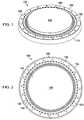
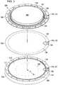
Figure 1 shows a perspective view of an illustrative embodiment of a disc pump having a perimeter valve configuration;Figure 2 shows a top view of the disc pump ofFigure 1 ;Figure 3 shows an exploded, perspective view of the disc pump ofFigure 1 ;Figure 4 shows a cross-section view of the disc pump ofFigure 1 ;Figure 4A shows a detail, cross-section view of the disc pump ofFigure 1 , showing the valve portion of the disc pump indicated inFigure 4 , where the valve portion is in a closed position;Figure 4B shows a detail, cross-section view of the disc pump ofFigure 1 , showing the valve portion of the disc pump indicated inFigure 4 , where the valve portion is in an open position;Figure 5A is a detail, top view of the portion of the isolator indicated inFigure 3 ;Figure 5B is a detail, top view of the portion of the valve flap indicated inFigure 3 ;Figure 5C is a detail, top view of the portion of the pump base indicated inFigure 3 ;Figure 6 shows a cross-section view of the disc pump ofFigure 1 ;Figure 6A shows a graph of pressure oscillations of fluid within the pump ofFigure 6 at a first time;Figure 6B shows a graph of pressure oscillations of fluid within the pump ofFigure 6 a half cycle later than the graph ofFigure 6A ;Figure 7 shows a detail, section view of the valve portion of the pump in the open position as fluid is motivated through the valve;Figure 8 shows a detail, section view of the valve portion of the pump as it begins to transition from the open position to the closed position;Figure 9 shows a detail, section view of the valve portion of the pump after it has transitioned to the closed position;Figure 10 shows a pressure graph of an oscillating differential pressure applied across the valve flap of the disc pump ofFigure 1 ;Figure 10A shows a graph of the position of the valve flap of the disc pump ofFigure 1 through an operating cycle of the valve; andFigure 10B shows a fluid-flow graph of an operating cycle of the disc pump ofFigure 1 as the valve flap transitions between an open and closed position.- In the following detailed description of illustrative embodiments, reference is made to the accompanying drawings that form a part hereof. By way of illustration, the drawings show specific preferred embodiments in which the invention may be practiced. These embodiments are described in sufficient detail to enable those skilled in the art to practice the invention, and it is understood that other embodiments may be utilized and that logical structural, mechanical, electrical, and chemical changes may be made without departing from the spirit or scope of the invention. To avoid detail not necessary to enable those skilled in the art to practice the embodiments described herein, the description may omit certain information known to those skilled in the art. The following detailed description is, therefore, not to be taken in a limiting sense, and the scope of the illustrative embodiments is defined only by the appended claims.
- A micropump, such as a disc pump, is a suitable application for a valve that operates at a high frequency, e.g., beyond the range of human hearing. At such frequencies, the pump may be extremely small in size and suitable for integration into a wide range of portable electronic devices where pressure or vacuum delivery is required. The disc pump may include an actuator, such as a piezoelectric actuator, to cause oscillatory motion and displacement oscillations of a driven end wall within the disc pump. When the actuator generates an oscillatory motion of the end wall, the displacement oscillations may generate radial oscillations of the fluid pressure within the pump. These radial oscillation of fluid pressure may cause fluid to flow through apertures in the pump base and apertures in the end wall, which may be inlet apertures and outlet apertures, respectively. To generate a pressure differential, the pump includes one or more valves that allow fluid to flow through the disc pump in only one direction. For the valves to operate at the high frequencies generated by the actuator, the valves may have an extremely fast response time such that the valves are able to open and close on a time scale that is shorter than the time scale of the pressure variations.
- Referring now to
Figures 1-5C and more specifically to the assembled, perspective view ofFigure 1 , an illustrative embodiment of adisc pump 100 is shown. Thedisc pump 100 comprises apump base 110, avalve flap 130, and anactuator 140 as shown in the exploded, perspective view ofFigure 3 . Theactuator 140 further comprises apiezoelectric disc 145 and anisolator 150 mechanically coupled to thepiezoelectric disc 145. Thepump base 110 comprises a generallycylindrical sidewall 111 closed at one end by afirst end wall 113 to form acavity 115 within thepump base 110. Thefirst end wall 113 may be generally planar or frusto-conical in shape as will be discussed in more detail below. The frusto-conical shape of thefirst end wall 113 may be, for example, deeper in the central portion of thepump base 110 and tapering upwardly toward theside wall 111. Thepump base 110 further comprises abase 116, anexternal sidewall 117, and anupper surface 119 having a ring-like shape extending between thesidewall 111 and theexternal sidewall 117. Theupper surface 119 of thepump base 110 includes a sealingsurface 121 adjacent the periphery of theside wall 111 and a plurality ofindentations 123 extending radially from the sealingsurface 121 below theupper surface 119. Thepump base 110 further comprisesapertures 125 extending from thefirst end wall 113 and out of thebase 116. Theapertures 125 may be positioned circumferentially around thebase 116 at a predetermined radius (a) from the center of thefirst end wall 113. - The
valve flap 130 is generally circular in shape having a cavity-facing surface and an isolator-facingsurface 132. The cavity-facing surface has a central portion that forms asecond end wall 131 that closes thecavity 115 of thepump base 110 and aperipheral portion 133 extending from theside wall 111 to cover theupper surface 119 of thepump base 110 on which thevalve flap 130 is mounted. Thevalve flap 130 comprisesperforations 135 positioned along theperipheral portion 133 of thevalve flap 130, each one of which is aligned over theindentations 123 in theupper surface 119 of thepump base 110. Theperforations 135 may include a plurality of the valve-flap apertures 531-535 (see, for example,Figure 5B ) extending through thevalve flap 130 to asingle indentation 123 to provide a path for fluid flow. The valve-flap apertures 531-535 may be arranged in a pattern to accommodate the geometry of theindentations 123 in theupper surface 119. For example, valve-flap apertures 531-535 may be arranged in an arcuate pattern to be adjacent the outer periphery of theindentation 123. The pattern and quantity of valve flap apertures 531-535 may be varied to control the total flow of fluid through thedisc pump 100 as desired. For example, the number of valve flap apertures 531-535 may be increased to increase the flow of fluid through thedisc pump 100. Similarly, the number of valve flap apertures 531-535 may be decreased to decrease the flow of fluid through thedisc ump 100. - About the periphery of the
disc pump 100, thevalve flap 130 is sandwiched between the isolator 150 and thepump base 110 so that the periphery is immobilized in a direction that is substantially perpendicular the surface of thevalve flap 130. Yet thevalve flap 130 is sufficiently flexible to allow the unconstrained portion of thevalve flap 130 to deform, thereby opening a fluid flow path from thecavity 115 toisolator valve apertures 155, as described in more detail below. - The
isolator 150 is also generally circular in shape and has a central portion and aperipheral portion 151. Thepiezoelectric disc 145 is mechanically coupled to a first side of theisolator 150 at the central portion. At theperipheral portion 151, the opposing side of theisolator 150 is mounted to thevalve flap 130 over theupper surface 119 of thepump base 110. Theperipheral portion 151 of theisolator 150 covers the isolator-facingsurface 132 of thevalve flap 130 which is sandwiched between the isolator 150 and theupper surface 119 of thepump base 110. Theisolator 150 comprisesrelief apertures 153 through theperipheral portion 151 extending radially outwardly from the periphery of thepiezoelectric disc 145 to provide additional flexibility when thepiezoelectric disc 145 is energized and vibrates. Theisolator 150 further comprisesisolator valve apertures 155 positioned between therelief apertures 153 and the edge of theperipheral portion 151 of theisolator 150, each one of which is aligned to provide an opening for theperforations 135 of thevalve flap 130. Theisolator valve apertures 155 extend radially inwardly from theperforations 135 and theside wall 111 to overlap aperipheral portion 157 of thecavity 115 with thevalve flap 130 still separating theisolator valve apertures 155 from thecavity 115. - Referring more specifically to
Figures 4A and 4B , thevalve flap 130 is sufficiently flexible and resilient to deform to form a fluid flow path and to return to its original shape to create a seal.Figure 4B shows thevalve flap 130 in the deformed, or open position in which thevalve flap 130 deforms within theisolator valve aperture 155 to form a path for fluid flow as shown byarrow 137.Figure 4A shows thevalve flap 130 in the sealed or closed position, in which thevalve flap 130 has returned to its original shape to close the fluid flow path illustrated inFigure 4B . When there is no pressure differential across thevalve flap 130, thevalve flap 130 is biased by the configuration of the pump elements and the resiliency of the material of thevalve flap 130 in the normally closed, or "close biased" position. In another embodiment, a spacer or shim may be included between thepump base 110 and thevalve flap 130 so that the valve will be biased in an open position. Inserting a spacer or shim may increase flow through thepump 100 by enlarging the fluid flow path between thevalve flap 130 and thepump base 110 when the valve is in the neutral position. - When the pressure in the
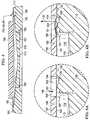
isolator valve aperture 155 equals or exceeds the pressure in thecavity 115 to create a differential pressure as indicated byarrow 138, theperipheral portion 133 of thevalve flap 130 remains seated on theupper surface 119 of thepump base 110 to block fluid flow to thecavity 115. Since this is the original shape of thevalve flap 130, thevalve flap 130 is the to be normally biased in a "closed position" in which thevalve flap 130 is substantially flat and seated on the sealingsurface 121 of thepump base 110. When the pressure in thecavity 115 exceeds the pressure in theisolator valve aperture 155 to create a differential pressure in the opposite direction, the resultant force and fluid flow motivates thevalve flap 130 away from the closed position to overcome the bias of thevalve flap 130 and break the seal with the sealingsurface 121 of thepump base 110. When thevalve flap 130 is in this deformed state, the fluid flow path is formed by thevalve flap 130 and theupper surface 119 of thepump base 110. As shown inFigure 4B , the fluid flow path extends from the opening created by theperipheral portion 157 of thecavity 115 to theindentations 123 where the fluid flow path exits through the valve-flap apertures 531-535 as shown inFigure 4B . Figures 5A, 5B, and 5C illustrate the features of theisolator 150, thevalve flap 130, and thepump base 110, respectively, that form the valves of thedisc pump 100. For example,Figure 5A shows theisolator valve apertures 155 that allow fluid to escape thecavity 115 of thepump base 110 when thevalve flap 130 is in the open position. In the assembled pump, theisolator valve apertures 155 generally overlie the valve flap apertures 531-535 shown inFigure 5B . The valve flap apertures 531-535 also allow fluid to escape thecavity 115 when thevalve flap 130 is in the open position. The valve flap apertures 531-535 generally overlie theindentations 123 of thepump base 110, shown inFigure 5C. Figure 5C also shows the sealing surfaces 121 of thepump base 110 that provide a reduced contact area adjacent theindentations 123. Thevalve flap 130 is motivated to the closed position by pressure and flow from theisolator valve aperture 155, and the surfaces of thepump base 110 that underlie theisolator valve aperture 155 support thevalve flap 130. Theindentations 123 serve to reduce the contact area between thevalve flap 130 and thepump base 110 so that when thevalve flap 130 is forced into the closed position, the force is applied over a smaller area of thepump base 110, which serves as the sealingsurface 121.- Turning now to
Figure 6 , the valve(s) defined by thepump base 110, thevalve flap 130, and theisolator 150 may be used in a pump that operates at extremely high frequencies, beyond the range of human hearing, for example. At such frequencies, the pump may be extremely small in size and suitable for integration into a wide range of portable electronic devices where pressure or vacuum delivery is required. Thedisc pump 100 comprises thepump base 110 having the substantiallycylindrical shape cavity 115 formed by theside wall 111 and closed at both ends by the substantiallycircular end walls disc pump 100 further comprises theactuator 140 operatively associated with the central portion of theend wall 131 to cause an oscillatory motion of theend wall 131 in a direction substantially perpendicular thereto with maximum amplitudes at about the center and periphery of theend wall 131, thereby generating displacement oscillations of theend wall 131 when in use. Thedisc pump 100 further comprises theisolator 150 operatively associated with the peripheral portion of theend wall 131 to reduce damping of displacement oscillations caused by the end wall's connection to theside wall 111 of thecavity 115. Thepump base 110 further comprises theapertures 125 disposed in theend wall 113. When theactuator 140 generates an oscillatory motion of theend wall 131, the displacement oscillations generate radial oscillations of the fluid pressure within thecavity 115 of thepump base 110 and cause fluid to flow through theapertures 125 and theisolator valve apertures 155, as indicated by thearrows - As noted above, the
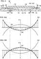
disc pump 100 also comprises a plurality of valves formed by the arrangement of thepump base 110, thevalve flap 130 and theisolator 150. The plurality of valves are disposed about the periphery of thedisc pump 100 and allow fluid to flow through thedisc pump 100 in only one direction, as described above. For the valves to operate at the high frequencies generated by theactuator 140, the valves must have an extremely fast response time such that the valves are able to open and close on a time scale significantly shorter than the time scale of the pressure variations. The valves are disposed about the periphery of thecavity 115 so that fluid is drawn into thecavity 115 only through theinlet apertures 125. The fluid is expelled from thecavity 115 through pump outlets formed by theisolator valve apertures 155 as indicated by thesolid arrows 128, thereby providing a source of reduced pressure at theinlet apertures 125. The term "reduced pressure" as used herein generally refers to a pressure less than the ambient pressure where thedisc pump 100 is located. Although the term "vacuum" and "negative pressure" may be used to describe the reduced pressure, the actual pressure reduction may be significantly less than the pressure reduction normally associated with a complete vacuum. The pressure is "negative" in the sense that it is a gauge pressure, i.e., the pressure is reduced below ambient atmospheric pressure. Unless otherwise indicated, values of pressure stated herein are gauge pressures. References to increases in reduced pressure typically refer to a decrease in absolute pressure, while decreases in reduced pressure typically refer to an increase in absolute pressure. Figure 6A shows one possible pressure oscillation profile illustrating the pressure oscillation within thecavity 115 resulting from the axial displacement oscillations of theend wall 131 described above. The solid curved line and arrows represent the pressure at one point in time, and the dashed curved line represents the pressure one half-cycle later. In this mode and higher-order modes, the amplitude of the pressure oscillations has a center pressure anti-node 210' around the center of thecavity 115 and aperipheral pressure anti-node 212 near theside wall 111 of thecavity 115 corresponding to the center displacement oscillations and the peripheral displacement oscillations (not shown) of theend wall 131. The amplitude of the pressure oscillations is substantially zero at anannular pressure node 214 between the center pressure anti-node 210' and theperipheral pressure anti-node 212. In an embodiment, theinlet apertures 125 of thepump base 110 are located at the same radial distance from the center of the cavity as theannular pressure node 214. The radial dependence of the pressure oscillations in thecavity 115 may be approximated by a Bessel function of the first kind. The radial change of the pressure is referred to as the "radial oscillations" of the fluid within thecavity 115 as distinguished from the axial pressure oscillations of the fluid within thecavity 115.- The pressure profile graphs of
Figures 6A and 6B illustrate that the greatest change in pressure is exhibited at the central pressure anti-node 210' andperipheral pressure anti-node 212 ofFigure 6A and thecentral pressure anti-node 210 and peripheral pressure anti-node 212' ofFigure 6B . To maximize flow through the pump, it may be advantageous to locate the valve(s) that enable flow at theperipheral pressure anti-node 212, where the greatest combination of pressure differential and surface area may be available to provide a flow path for fluid through thedisc pump 100. - Returning to
Figure 6 , the fluid flow through theinlet apertures 125 as indicated by thesolid arrows 126 corresponds to the fluid flow through theisolator valve apertures 155, as indicated by thesolid arrows 128. As indicated above, the operation of the valves and the movement of thevalve flap 130 between the open and closed positions is a function of the change in direction of the differential pressure (ΔP) of the fluid at the periphery of thecavity 115 for this embodiment of a disc pump. The differential pressure (ΔP) is assumed to be substantially uniform about the periphery of thecavity 115 because theside wall 111 location corresponds to theperipheral pressure anti-node 212 that is generated by the displacement oscillations of theend wall 131. Placing a large number ofvalve apertures 155 about the perimeter of thecavity 115 may enhance flow through thepump 100. Where a single valve at the center of a cavity places a valve at a singular high pressure area, the single valve is limited because the area of high pressure, the central pressure anti-node, is localized at the center of thecavity 115. Conversely, a multitude ofvalve apertures 155 about the perimeter of thecavity 115 may facilitate enhanced flow because thevalve apertures 155 are spaced about an area of thecavity 115 that spans the cavity perimeter (i.e., the peripheral pressure anti-node). Figures 7-9 illustrate the operation of thevalve flap 130 in response to the radial pressure oscillations. InFigure 7 , thevalve flap 130 is motivated away from the sealingsurface 121 into the open position when the differential pressure across thevalve flap 130 is a positive differential pressure (+ΔP). Thus, when the differential pressure results in a higher pressure in thecavity 115 than in theisolator valve aperture 155, the resultant flow of fluid motivates thevalve flap 130 away from the sealingsurface 121 of thepump base 110 into the open position. The movement of thevalve flap 130 unblocks a fluid flow path between the sealingsurface 121 and thevalve flap 130 so that fluid is permitted to flow from thecavity 115 through the valve flap apertures 531-535 andisolator valve apertures 155, as indicated by thearrow 137.Figure 8 illustrates that in the absence of a pressure differential and the related fluid flow from thecavity 115, thevalve flap 130 begins to move to the closed position. Thus, when the differential pressure changes back to the negative differential pressure (-ΔP), fluid begins to flow in the opposite direction as indicated by thearrow 139. Thearrow 139 indicates the path of a small amount of fluid back flow, i.e., flow back through theisolator valve aperture 155. The backflow and pressure differential exert a force on thevalve flap 130 that motivates thevalve flap 130 to the closed position.- In the closed position illustrated in
Figure 9 ,valve flap 130 contacts the sealingsurface 121, thereby blocking the fluid flow path illustrated by thearrow 137 ofFigure 7 . As such, thevalve flap 130 may act as a check valve that allows fluid to flow from thecavity 115 to theisolator valve aperture 155 in the open position before quickly returning to the closed position to block fluid from flowing in the opposite direction from theisolator valve aperture 155 to thecavity 115. In this manner, the pressure oscillations in thecavity 115 cycle thevalve flap 130 between the closed and open positions, and thedisc pump 100 provides a reduced pressure every half cycle when thevalve flap 130 is in the open position. - In steady-state operation, pressure is applied against
valve flap 130 by fluid in thecavity 115, which motivates thevalve flap 130 away from the sealingsurface 121, as shown inFigure 7 . As a result, the valve flap moves from the closed position to an open position over a period of time, i.e., an opening time delay (To), allowing fluid to flow in the direction indicated by thearrow 137. When the pressure is reversed, thevalve flap 130 springs back against the sealingsurface 121 to the closed position. When the pressure changes direction, fluid will flow in the reverse direction for a very short time period, a closing time delay (Tc), as indicated by thearrows 139 shown inFigure 8 . The differential pressure causes thevalve flap 130 to block the flow path by sealing against the sealingsurface 121, as shown inFigure 9 . - The opening and closing of the
valve flap 130 is a function of the change in direction of the differential pressure (ΔP) of the fluid across thevalve flap 130. InFigure 8 , the differential pressure has been assigned a negative value (-ΔP) as indicated by the downward pointing arrow. In this embodiment, when the differential pressure has a negative value (-ΔP), the fluid pressure in theisolator valve aperture 155 is greater than the fluid pressure in thecavity 115. This negative differential pressure (-ΔP) drives thevalve flap 130 into the fully closed position as described above, wherein thevalve flap 130 is pressed against the sealingsurface 121 to block the flow path between thevalve flap 130 and the sealingsurface 121 and prevent the flow of fluid through thedisc pump 100. When the differential pressure across thevalve flap 130 reverses to become a positive differential pressure (+ΔP) as indicated by theupward pointing arrow 137 inFigure 7 , thevalve flap 130 is again motivated away from the sealingsurface 121 and against theisolator 150 into the open position. In this embodiment, when the differential pressure has a positive value (+ΔP), the fluid pressure in thecavity 115 is greater than the fluid pressure in theisolator valve aperture 155. - When the differential pressure changes back to a negative differential pressure (-ΔP) as indicated by the downward pointing arrow in
Figure 8 , fluid begins flowing in the opposite direction as indicated by thearrow 139, which forces thevalve flap 130 back toward the closed position shown inFigure 9 . InFigure 9 , the fluid pressure applied to the cavity side of thevalve flap 130 is less than the fluid pressure applied to the isolator side of thevalve flap 130. Thus, thevalve flap 130 experiences a net force, represented byarrow 138, which accelerates thevalve flap 130 toward the sealingsurface 121 to close a valve formed by the arrangement of thevalve flap 130,pump base 110, andisolator 150. In this manner, the changing differential pressure cycles thevalve flap 130 between closed and open positions based on the direction (i.e., positive or negative) of the differential pressure across thevalve flap 130. - The differential pressure (ΔP) is assumed to be substantially uniform at the locations of the valves because the valve locations correspond to the
peripheral pressure anti-node 212, as described above. Consequently, the cycling of the differential pressure (ΔP) between the positive differential pressure (+ΔP) and negative differential pressure (-ΔP) values can be represented by a square wave over the positive pressure time period (tP+) and the negative pressure time period (tP-), respectively, as shown inFigure 10 . As differential pressure (ΔP) cycles thevalve flap 130 between the closed and open positions, thedisc pump 100 provides a reduced pressure every half cycle when thevalve flap 130 is in the open position subject to the opening time delay (To) and the closing time delay (Tc) as also described above and as shown inFigure 10A . When the differential pressure across the valve flap is initially negative with thevalve flap 130 closed (seeFigure 9 ) and reverses to become a positive differential pressure (+ΔP), thevalve flap 130 is motivated away from the sealingsurface 121 into the open position (seeFigure 7 ) after the opening time delay (To). In this position, the movement of thevalve flap 130 unblocks the flow path between the sealingsurface 121 and thevalve flap 130 so that fluid is permitted to flow through the valve flap apertures 531-535 and overlyingisolator valve apertures 155 of theisolator 150, thereby providing a source of reduced pressure outside theinlet apertures 125 of thedisc pump 100 over an open time period (to), as shown inFigure 10B . When the differential pressure changes back to the negative differential pressure (-ΔP), fluid begins to flow in the opposite direction through the valve (seeFigure 8 ) which forces thevalve flap 130 back toward the closed position after the closing time delay (Tc). Thevalve flap 130 remains closed for the remainder of the half cycle or closed time period (tc). - Regarding material selection, the
isolator 150 should be rigid enough to withstand the fluid pressure oscillations to which it is subjected without significant mechanical deformation relative to thevalve flap 130 at the periphery of thecavity 115. As such, theisolator 150 may be formed from a polymer sheet material of uniform thickness such as, for example, PET or Kapton. In one embodiment, theisolator 150 may be made from Kapton sheeting having a thickness of less than about 200 microns. Theisolator 150 may also be made from a thin metal sheet of uniform thickness such as, for example, steel or brass, or another suitable flexible material. In another embodiment, theisolator 150 may be made from steel sheeting having a thickness of less than about 20 microns. Theisolator 150 may be made of another flexible material suitable to facilitate vibration of theactuator 140 as described above. Theisolator 150 may be glued, welded, clamped, soldered, or otherwise attached to theactuator 140 depending on the material used, and either the same process or a different process may be used to attach theisolator 150 to thepump base 110. - The
valve flap 130 may be formed from a lightweight material, such as a metal or polymer film. In one embodiment, when fluid pressure oscillations of about 20 kHz or greater are present, thevalve flap 130 may be formed from a thin polymer sheet between about 1 micron and about 20 microns in thickness. For example, thevalve flap 130 may be formed from polyethylene terephthalate (PET) or a liquid crystal polymer film approximately 3 microns in thickness. As shown inFigure, 8 , theillustrative valve flap 130 merely flexes under the influence of a differential pressure and does not experience significant accelerations as would, for example, a valve flap being disposed a greater distance from theisolator 150. Nonetheless, the valve flap material should be robust enough to withstand the repeated flexing resulting from the oscillating differential pressure described above. In addition, minimizing the pressure drop incurred as air flows through the valve is important to maximizing valve performance as the pressure drop affects both the maximum flow rate and the maximum differential pressure that is achievable. Reducing the size of the valve flap apertures 531-535 increases the flow resistance and the pressure drop through the valve. According to an embodiment, analysis employing computational models and steady-state flow equations to approximate flow resistance through the valves may be used to improve the operation of the valves. - To estimate the pressure drop for flow through the apertures, a computational model may be applied that considers the fluid dynamic viscosity, the flow rate through the apertures, and the thickness of the
valve flap 130. When thevalve flap 130 is in the open position shown inFigure 7 , the flow of fluid through the gap between thevalve flap 130 and the sealingsurface 121 and the valve flap apertures 531-535 will propagate generally radially after exiting the valve flap apertures 531-535. Thus, the total pressure drop across the valve may be very sensitive to changes in the size of the valve flap apertures 531-535 as well as the gap (dgap) between thevalve flap 130 and the sealingsurface 121 when thevalve flap 130 is in the open position. It should be noted that a smaller gapdgap, which can be desirable in order to minimize the opening time delay (To) and the closing time delay (Tc) of thevalve flap 130, may increase the pressure loss. For example, reducing the flap gapdgap from about 25 microns to about 20 microns may double the pressure loss. - Consideration also should be given to maintaining the stress experienced by the
valve flap 130 within acceptable limits during operation of the valve, which typically requires alarger sealing surface 121. In one embodiment, the gapdgap value may be selected such that the gap pressure drop is equal to the hole pressure drop. In one embodiment, the size of the gapdgap falls within an approximate range between about 5 microns and about 150 microns, although more preferably within a range between about 15 and about 50 microns. Figure 7 illustrates a valve portion of the disc pump ofFigure 1 in the open position. In this position, thevalve flap 130 is subjected to stress as thevalve flap 130 opens the gap that serves as the flow path between thevalve flap 130 and the sealingsurface 121. The opening of the valve causes thevalve flap 130 to deform toward theisolator 150 to allow fluid to flow through the valve flap aperture 531-535 as illustrated. The level of stress on thevalve flap 130 in this configuration increases with the diameter of theisolator valve aperture 155 in theisolator 150. The material of thevalve flap 130 will tend to fracture more easily if the diameter of theisolator valve aperture 155 is too large, thus leading to failure of thedisc pump 100. In order to reduce the likelihood that the material of thevalve flap 130 fractures, the size of theisolator valve apertures 155 may be reduced to limit the stress experienced by thevalve flap 130 to a level which is below the fatigue stress of the material of thevalve flap 130.- The maximum stress experienced by the material of the
valve flap 130 in operation may be estimated using computational models. In one embodiment of the invention, thevalve flap 130 is formed from a thin polymer sheet, such as Mylar having a Poisson ratio of 0.3, and is clamped to the sealingsurface 121 about the perimeter of thepump base 110. Considering the high number of stress cycles applied to thevalve flap 130 during the operation of the valve, the maximum stress per cycle tolerated by thevalve flap 130 should be significantly lower than the yield stress of the material of thevalve flap 130. Limiting the maximum stress per cycle to be significantly less than the yield stress of the material of thevalve flap 130 in order to reduce the possibility that thevalve flap 130 suffers a fatigue fracture, especially at the portion of thevalve flap 130 that flexes upward to allow fluid flow. Based on fatigue data compiled for a high number of cycles with respect to similar valve structures, it has been determined that the actual yield stress of the material of thevalve flap 130 should be at least about four times greater than the stress applied to the material of the valve flap 130 (e.g., 16, 34, and 43 MPa as calculated above). Thus, the valve flap material should have a yield stress as high as 150 MPa to minimize the likelihood of such fractures for a maximum equivalent diameter of theisolator valve apertures 155 in this case of approximately 200 microns. - Reducing the equivalent diameter of the
isolator valve apertures 155 beyond the maximum equivalent diameter of theisolator valve apertures 155 may be desirable as it further reducesvalve flap 130 stress and has no significant effect on valve flow resistance until the diameter of the equivalentisolator valve apertures 155 approaches the same size as the gapdgap. Further, reduction in the size of theisolator valve apertures 155 permits the inclusion of an increased number ofisolator valve apertures 155 per unit area of the isolator surface for a given sealing length (s). However, the size of theisolator valve apertures 155 may be limited, at least in part, by the manner in which theisolator 150 is fabricated. For example, chemical etching limits the size of theisolator valve apertures 155 to be equal to or greater than the thickness of theisolator 150 in order to achieve repeatable and controllable results. In one embodiment, theisolator valve apertures 155 in theisolator 150 are between about 20 microns and about 500 microns in diameter. In other embodiments theisolator valve apertures 155 in theisolator 150 are between about 100 and about 200 microns in diameter depending on the other factors described above. - Within the
disc pump 100, the thickness of the material of the valve flap 130 (e.g., 3 µm Mylar) is a factor in the speed of the valve operation and therefore a contributor to the performance of thedisc pump 100. As a result, pumps assembled with about a 1.5µm valve flap 130 with about a 20 µm gap may yield increased performance over valves having about a 3 µm valve flap with about a 20 µm gap. A wider valve gap may also increase performance, such that about a 60 µm gap may yield improved performance over about a 20 µm gap with about a 3µm valve flap 130. It is possible to increase performance by creating a valve having, for example, athinner valve flap 130 of about a 1.5 µm thickness and about a 60 µm gap. Yet to create such a valve, material concerns must be overcome to address the additional strain place on a thinner material. This concern is mitigated by biasing thevalve flap 130 toward the center of thevalve cavity 115. The individual valve flap apertures 531-535 may be formed partially by precision injection molding thevalve flap 130, and partly by laser drilling or a similar process. To form thepump 100 and integrated valves, thevalve flap 130 can be directly mounted to theisolator 150. Theisolator 150 andvalve flap 130 may then be fastened to thepump base 110 by a suitable joining process, such as heat staking. - The inlet apertures 125 are shown in, e.g.,
Figure 6 , as being located at theannular pressure node 214. Yet in another embodiment theinlet apertures 125 may instead be located near the center of the of thepump base 110 at thecentral pressure anti-node 210. In such an embodiment, a ring-like isolator structure and a valve flap structure may be installed adjacent theinlet apertures 125, thereby creating an inlet valve. In such an embodiment, the valve structure discussed above would function as an outlet valve, or exhaust valve. Alternatively, a peripheral valve arrangement discussed above may be installed at thepump base 110, thereby utilizing the center pressure anti-node to increase the pressure in the cavity of the pump before further increasing the pressure at the exhaust valve, e.g., theisolator valve aperture 155, as discussed above. - Together, the illustrative embodiments provide a method for forming valves around the periphery of a
pump cavity 115 at the location of theperipheral pressure anti-node 212. By providing an increased area for including valves in thepump cavity 115, thedisc pump 100 of the illustrative embodiments may provide greater flow than a similar pump having a centrally mounted valve. By isolating incorporating a multitude of small valves into the structure of thedisc pump 100, manufacturing may be simplified. Moreover, the multitude of valves provides a degree of redundancy, such that if one of the valve flap apertures is blocked or is fractured, the remaining valves will remain functional. - It should be apparent from the foregoing that embodiments having significant advantages have been provided. While the embodiments are shown in only a few of its forms, it is not just limited but is susceptible to various changes and modifications without departing from the scope of the appended claims.
Claims (18)
- A disc pump (100) comprising:a pump base (110) having an elliptical sidewall (111) closed at one end by a first end wall (113) to form a cavity (115) and an upper surface (119) extending radially outwardly from the sidewall (111), the upper surface (119) including a sealing surface (121) and at least one indentation (123);at least one aperture (125) extending through the pump base (110) into the cavity (115); andan actuator (140) including a piezoelectric disc (145) and an isolator (150) extending radially outwardly between the piezoelectric disc (145) and the sidewall (111), the disc pump beingcharacterized in that;the isolator (150) has at least one isolator valve aperture (155) extending through the isolator (150) and having an opening proximate the upper surface (119) of the pump base (110) and a peripheral portion (157) of the cavity (115), andin that the disc pump further comprises;a valve flap (130) disposed between the opening of the isolator valve aperture (155) on one side and the upper surface (119) of the pump base (110) and the peripheral portion (157) of the cavity (115) on the other side, the valve flap (130) having at least one valve flap aperture (531-535) extending between the opening of the isolator valve aperture (155) and the indentation (123),wherein the valve flap (130) prevents the flow of fluids through the isolator valve aperture (155) when seated against the sealing surface (121) and permits the flow of fluids through the indentation (123) and the isolator valve aperture (155) when not seated against the sealing surface (121).
- The disc pump (100) of claim 1, wherein the at least one aperture (125) comprises a plurality of apertures (125) circumferentially disposed about a center of the first end wall (113).
- The disc pump (100) of claim 1, wherein the at least one aperture (125) comprises a plurality of apertures (125) circumferentially disposed about a center of the first end wall (113) at a predetermined distance (a) from the center of the first end wall (113).
- The disc pump (100) of claim 1, wherein the at least one aperture (125) comprises a plurality of apertures (125) circumferentially disposed about a center of the first end wall (113) at a predetermined distance (a) from the center of the first end wall (113) corresponding to the radial distance of an annular pressure node (214) from the center of the first end wall (113).
- The disc pump (100) of claim 1, wherein the at least one indentation (123) comprises a plurality of indentations (123) circumferentially disposed in the upper surface (119) proximate to a periphery (157) of the cavity (115).
- The disc pump (100) of claim 1, wherein the at least one isolator valve aperture (155) comprises a plurality of isolator valve apertures (155) circumferentially disposed around a periphery (151) of the isolator (150).
- The disc pump (100) of claim 1, wherein the at least one valve flap aperture (155) comprises a plurality of valve flap apertures (155) circumferentially disposed around a periphery (133) of the valve flap (130).
- The disc pump (100) of claim 1, wherein the at least one indentation (123) comprises a plurality of indentations (123) circumferentially disposed in the upper surface (119) proximate to a periphery (157) of the cavity (115), the at least one isolator valve aperture (155) comprises a plurality of isolator valve apertures (155) circumferentially disposed around a periphery (151) of the isolator, and the at least one valve flap aperture (531-535) comprises a plurality of valve flap apertures (531-535), and wherein the indentations (123), the isolator valve apertures (155), and the valve flap apertures (531-535) are substantially aligned.
- The disc pump (100) of claim 1, wherein the at least one indentation (123) comprises a plurality of indentations (123) circumferentially disposed in the upper surface (119) proximate to a periphery (157) of the cavity (115), the at least one isolator valve aperture (155) comprises a plurality of isolator valve apertures (155) circumferentially disposed around a periphery (151) of the isolator (150), and the at least one valve flap aperture (531-535) comprises a plurality of valve flap apertures (531-535), and wherein the indentations (123) and the isolator valve apertures (155) are substantially aligned and each respective indentation (123) and isolator valve aperture (155) is aligned with a respective plurality of valve flap apertures (531-535).
- The disc pump (100) of claim 1, wherein the valve flap (130) includes at least one perforation (135) disposed on the peripheral portion (133) of the valve flap (130) and adjacent the at least one indentation (123).
- The disc pump (100) of claim 1, wherein the valve flap (130) includes a plurality of perforations (135) disposed on the peripheral portion (133) of the valve flap (130), the at least one indentation (123) comprises a plurality of indentations (123), and the plurality ofperforations (135) are adjacent the plurality of indentations (123).
- The disc pump (100) of claim 1, wherein the valve flap (130) includes at least one perforation (135) disposed on the peripheral portion (133) of the valve flap (130) and adjacent the at least one indentation (123), the at least one valve flap aperture (531-535) comprises a plurality of valve flap apertures (531-535), and the at least one perforation (135) includes the plurality ofvalve flap apertures (531-535).
- The disc pump (100) of claim 1, wherein the valve flap (130) includes at least one perforation (135) disposed on the peripheral portion (133) of the valve flap (130) and adjacent the at least one indentation (123), the at least one valve flap aperture (531-535) comprises a plurality of valve flap apertures (531-535), and the at least one perforation (123) includes the plurality ofvalve flap apertures (531-535) arranged in an arcuate pattern adjacent the outer periphery of the indentation (123).
- The disc pump (100) of claim 1, wherein the isolator valve aperture (155) extends generally perpendicularly through the isolator (150).
- The disc pump (100) of claim 1, wherein the valve flap (130) is formed from:a light-weight material selected from the group consisting of a polymer and a metal; ora polymer having a thickness of about less than about 20 microns and preferably about 1.5 microns; ora polyethylene terephthalate having a thickness about 1.5 microns; ora liquid crystal film having a thickness of about 1.5 microns; ora Mylar film having a thickness of about 1.5 microns.
- The disc pump (100) of claim 1, wherein the isolator (150) is heat staked to the pump base (110).
- A method for providing a flow of a fluid, the method comprising:providing the disc pump (100) of any of claims 1-16:generating radial oscillations of the fluid pressure by energizing the piezoelectric disc (145) to cause displacement oscillations of the actuator (140);if the radial oscillations of the fluid pressure generate a higher pressure in the cavity (115) than an ambient pressure adjacent the isolator valve aperture (155), deforming the valve flap (130) into the isolator valve aperture (155) and away from the sealing surface (121) to permit fluid to flow through the indentations (123), the valve flap apertures (531-535), and the isolator valve apertures (155); andif the radial oscillations of the fluid pressure do not generate a higher pressure in the cavity (115) than the ambient pressure adjacent the isolator valve aperture (155), motivating the valve flap (130) against the sealing surface (121) to prevent fluid from flowing through the indentations (123), the valve flap apertures (531-535), and the isolator valve apertures (155).
- The method of claim 17, wherein the valve flap (130) has a response time delay less than about twenty-five percent of a time period of the radial oscillations of the fluid pressure.
Applications Claiming Priority (2)
| Application Number | Priority Date | Filing Date | Title |
|---|---|---|---|
| US201261635655P | 2012-04-19 | 2012-04-19 | |
| PCT/US2013/036805WO2013158659A1 (en) | 2012-04-19 | 2013-04-16 | Disc pump with perimeter valve configuration |
Publications (2)
| Publication Number | Publication Date |
|---|---|
| EP2855937A1 EP2855937A1 (en) | 2015-04-08 |
| EP2855937B1true EP2855937B1 (en) | 2016-05-25 |
Family
ID=48190639
Family Applications (1)
| Application Number | Title | Priority Date | Filing Date |
|---|---|---|---|
| EP13718987.4AActiveEP2855937B1 (en) | 2012-04-19 | 2013-04-16 | Disc pump with perimeter valve configuration |
Country Status (3)
| Country | Link |
|---|---|
| US (1) | US9334858B2 (en) |
| EP (1) | EP2855937B1 (en) |
| WO (1) | WO2013158659A1 (en) |
Cited By (20)
| Publication number | Priority date | Publication date | Assignee | Title |
|---|---|---|---|---|
| US10660994B2 (en) | 2012-03-12 | 2020-05-26 | Smith & Nephew Plc | Reduced pressure apparatus and methods |
| USD898925S1 (en) | 2018-09-13 | 2020-10-13 | Smith & Nephew Plc | Medical dressing |
| US10898388B2 (en) | 2015-04-27 | 2021-01-26 | Smith & Nephew Plc | Reduced pressure apparatuses and methods |
| US11096831B2 (en) | 2016-05-03 | 2021-08-24 | Smith & Nephew Plc | Negative pressure wound therapy device activation and control |
| US11116669B2 (en) | 2016-08-25 | 2021-09-14 | Smith & Nephew Plc | Absorbent negative pressure wound therapy dressing |
| US11123471B2 (en) | 2017-03-08 | 2021-09-21 | Smith & Nephew Plc | Negative pressure wound therapy device control in presence of fault condition |
| US11160915B2 (en) | 2017-05-09 | 2021-11-02 | Smith & Nephew Plc | Redundant controls for negative pressure wound therapy systems |
| US11173240B2 (en) | 2016-05-03 | 2021-11-16 | Smith & Nephew Plc | Optimizing power transfer to negative pressure sources in negative pressure therapy systems |
| US11285047B2 (en) | 2016-04-26 | 2022-03-29 | Smith & Nephew Plc | Wound dressings and methods of use with integrated negative pressure source having a fluid ingress inhibition component |
| US11305047B2 (en) | 2016-05-03 | 2022-04-19 | Smith & Nephew Plc | Systems and methods for driving negative pressure sources in negative pressure therapy systems |
| US11497653B2 (en) | 2017-11-01 | 2022-11-15 | Smith & Nephew Plc | Negative pressure wound treatment apparatuses and methods with integrated electronics |
| US11554203B2 (en) | 2017-11-01 | 2023-01-17 | Smith & Nephew Plc | Negative pressure wound treatment apparatuses and methods with integrated electronics |
| US11564845B2 (en) | 2017-09-13 | 2023-01-31 | Smith & Nephew Plc | Negative pressure wound treatment apparatuses and methods with integrated electronics |
| US11564847B2 (en) | 2016-09-30 | 2023-01-31 | Smith & Nephew Plc | Negative pressure wound treatment apparatuses and methods with integrated electronics |
| US11701265B2 (en) | 2017-09-13 | 2023-07-18 | Smith & Nephew Plc | Negative pressure wound treatment apparatuses and methods with integrated electronics |
| US11707564B2 (en) | 2017-11-01 | 2023-07-25 | Smith & Nephew Plc | Safe operation of integrated negative pressure wound treatment apparatuses |
| US11723809B2 (en) | 2016-03-07 | 2023-08-15 | Smith & Nephew Plc | Wound treatment apparatuses and methods with negative pressure source integrated into wound dressing |
| US12005181B2 (en) | 2016-12-12 | 2024-06-11 | Smith & Nephew Plc | Pressure wound therapy status indication via external device |
| US12005182B2 (en) | 2019-05-31 | 2024-06-11 | T.J.Smith And Nephew, Limited | Systems and methods for extending operational time of negative pressure wound treatment apparatuses |
| US12083263B2 (en) | 2019-03-20 | 2024-09-10 | Smith & Nephew Plc | Negative pressure wound treatment apparatuses and methods with integrated electronics |
Families Citing this family (7)
| Publication number | Priority date | Publication date | Assignee | Title |
|---|---|---|---|---|
| EP3604810B1 (en)* | 2014-02-21 | 2023-06-28 | Murata Manufacturing Co., Ltd. | Fluid control device and pump |
| WO2019073739A1 (en)* | 2017-10-10 | 2019-04-18 | 株式会社村田製作所 | Pump and fluid control device |
| JP6741176B2 (en)* | 2018-01-10 | 2020-08-19 | 株式会社村田製作所 | Pumps and fluid controls |
| WO2020111064A1 (en) | 2018-11-27 | 2020-06-04 | 株式会社村田製作所 | Pump |
| EP3828414B1 (en)* | 2018-11-27 | 2024-08-14 | Murata Manufacturing Co., Ltd. | Pump |
| GB2583880A (en)* | 2020-07-31 | 2020-11-11 | Ttp Ventus Ltd | Actuator for a resonant acoustic pump |
| GB2624475B (en) | 2023-02-08 | 2025-06-18 | Foster & Freeman Ltd | Volatile sampling device |
Family Cites Families (134)
| Publication number | Priority date | Publication date | Assignee | Title |
|---|---|---|---|---|
| US1355846A (en) | 1920-02-06 | 1920-10-19 | David A Rannells | Medical appliance |
| US2547758A (en) | 1949-01-05 | 1951-04-03 | Wilmer B Keeling | Instrument for treating the male urethra |
| US2632443A (en) | 1949-04-18 | 1953-03-24 | Eleanor P Lesher | Surgical dressing |
| GB692578A (en) | 1949-09-13 | 1953-06-10 | Minnesota Mining & Mfg | Improvements in or relating to drape sheets for surgical use |
| US2682873A (en) | 1952-07-30 | 1954-07-06 | Johnson & Johnson | General purpose protective dressing |
| NL189176B (en) | 1956-07-13 | 1900-01-01 | Hisamitsu Pharmaceutical Co | PLASTER BASED ON A SYNTHETIC RUBBER. |
| US2969057A (en) | 1957-11-04 | 1961-01-24 | Brady Co W H | Nematodic swab |
| US3066672A (en) | 1960-09-27 | 1962-12-04 | Jr William H Crosby | Method and apparatus for serial sampling of intestinal juice |
| US3367332A (en) | 1965-08-27 | 1968-02-06 | Gen Electric | Product and process for establishing a sterile area of skin |
| US3520300A (en) | 1967-03-15 | 1970-07-14 | Amp Inc | Surgical sponge and suction device |
| US3568675A (en) | 1968-08-30 | 1971-03-09 | Clyde B Harvey | Fistula and penetrating wound dressing |
| US3682180A (en) | 1970-06-08 | 1972-08-08 | Coilform Co Inc | Drain clip for surgical drain |
| BE789293Q (en) | 1970-12-07 | 1973-01-15 | Parke Davis & Co | MEDICO-SURGICAL DRESSING FOR BURNS AND SIMILAR LESIONS |
| US3826254A (en) | 1973-02-26 | 1974-07-30 | Verco Ind | Needle or catheter retaining appliance |
| DE2527706A1 (en) | 1975-06-21 | 1976-12-30 | Hanfried Dr Med Weigand | DEVICE FOR THE INTRODUCTION OF CONTRAST AGENTS INTO AN ARTIFICIAL INTESTINAL OUTLET |
| DE2640413C3 (en) | 1976-09-08 | 1980-03-27 | Richard Wolf Gmbh, 7134 Knittlingen | Catheter monitor |
| NL7710909A (en) | 1976-10-08 | 1978-04-11 | Smith & Nephew | COMPOSITE STRAPS. |
| GB1562244A (en) | 1976-11-11 | 1980-03-05 | Lock P M | Wound dressing materials |
| US4080970A (en) | 1976-11-17 | 1978-03-28 | Miller Thomas J | Post-operative combination dressing and internal drain tube with external shield and tube connector |
| US4139004A (en) | 1977-02-17 | 1979-02-13 | Gonzalez Jr Harry | Bandage apparatus for treating burns |
| US4184510A (en) | 1977-03-15 | 1980-01-22 | Fibra-Sonics, Inc. | Valued device for controlling vacuum in surgery |
| US4165748A (en) | 1977-11-07 | 1979-08-28 | Johnson Melissa C | Catheter tube holder |
| US4245637A (en) | 1978-07-10 | 1981-01-20 | Nichols Robert L | Shutoff valve sleeve |
| SE414994B (en) | 1978-11-28 | 1980-09-01 | Landstingens Inkopscentral | VENKATETERFORBAND |
| GB2047543B (en) | 1978-12-06 | 1983-04-20 | Svedman Paul | Device for treating tissues for example skin |
| US4266545A (en) | 1979-04-06 | 1981-05-12 | Moss James P | Portable suction device for collecting fluids from a closed wound |
| US4284079A (en) | 1979-06-28 | 1981-08-18 | Adair Edwin Lloyd | Method for applying a male incontinence device |
| US4261363A (en) | 1979-11-09 | 1981-04-14 | C. R. Bard, Inc. | Retention clips for body fluid drains |
| US4569348A (en) | 1980-02-22 | 1986-02-11 | Velcro Usa Inc. | Catheter tube holder strap |
| WO1981002516A1 (en) | 1980-03-11 | 1981-09-17 | E Schmid | Cushion for holding an element of grafted skin |
| US4297995A (en) | 1980-06-03 | 1981-11-03 | Key Pharmaceuticals, Inc. | Bandage containing attachment post |
| US4333468A (en) | 1980-08-18 | 1982-06-08 | Geist Robert W | Mesentery tube holder apparatus |
| US4465485A (en) | 1981-03-06 | 1984-08-14 | Becton, Dickinson And Company | Suction canister with unitary shut-off valve and filter features |
| US4392853A (en) | 1981-03-16 | 1983-07-12 | Rudolph Muto | Sterile assembly for protecting and fastening an indwelling device |
| US4373519A (en) | 1981-06-26 | 1983-02-15 | Minnesota Mining And Manufacturing Company | Composite wound dressing |
| US4392858A (en) | 1981-07-16 | 1983-07-12 | Sherwood Medical Company | Wound drainage device |
| US4419097A (en) | 1981-07-31 | 1983-12-06 | Rexar Industries, Inc. | Attachment for catheter tube |
| SE429197B (en) | 1981-10-14 | 1983-08-22 | Frese Nielsen | SAR TREATMENT DEVICE |
| DE3146266A1 (en) | 1981-11-21 | 1983-06-01 | B. Braun Melsungen Ag, 3508 Melsungen | COMBINED DEVICE FOR A MEDICAL SUCTION DRAINAGE |
| US4551139A (en) | 1982-02-08 | 1985-11-05 | Marion Laboratories, Inc. | Method and apparatus for burn wound treatment |
| US4475909A (en) | 1982-05-06 | 1984-10-09 | Eisenberg Melvin I | Male urinary device and method for applying the device |
| EP0100148B1 (en) | 1982-07-06 | 1986-01-08 | Dow Corning Limited | Medical-surgical dressing and a process for the production thereof |
| NZ206837A (en) | 1983-01-27 | 1986-08-08 | Johnson & Johnson Prod Inc | Thin film adhesive dressing:backing material in three sections |
| US4548202A (en) | 1983-06-20 | 1985-10-22 | Ethicon, Inc. | Mesh tissue fasteners |
| US4540412A (en) | 1983-07-14 | 1985-09-10 | The Kendall Company | Device for moist heat therapy |
| US4543100A (en) | 1983-11-01 | 1985-09-24 | Brodsky Stuart A | Catheter and drain tube retainer |
| US4525374A (en) | 1984-02-27 | 1985-06-25 | Manresa, Inc. | Treating hydrophobic filters to render them hydrophilic |
| CA1286177C (en) | 1984-05-03 | 1991-07-16 | Smith And Nephew Associated Companies Plc | Adhesive wound dressing |
| US4897081A (en) | 1984-05-25 | 1990-01-30 | Thermedics Inc. | Percutaneous access device |
| US5215522A (en) | 1984-07-23 | 1993-06-01 | Ballard Medical Products | Single use medical aspirating device and method |
| GB8419745D0 (en) | 1984-08-02 | 1984-09-05 | Smith & Nephew Ass | Wound dressing |
| US4872450A (en) | 1984-08-17 | 1989-10-10 | Austad Eric D | Wound dressing and method of forming same |
| US4826494A (en) | 1984-11-09 | 1989-05-02 | Stryker Corporation | Vacuum wound drainage system |
| US4655754A (en) | 1984-11-09 | 1987-04-07 | Stryker Corporation | Vacuum wound drainage system and lipids baffle therefor |
| US4605399A (en) | 1984-12-04 | 1986-08-12 | Complex, Inc. | Transdermal infusion device |
| US5037397A (en) | 1985-05-03 | 1991-08-06 | Medical Distributors, Inc. | Universal clamp |
| US4640688A (en) | 1985-08-23 | 1987-02-03 | Mentor Corporation | Urine collection catheter |
| US4710165A (en) | 1985-09-16 | 1987-12-01 | Mcneil Charles B | Wearable, variable rate suction/collection device |
| US4758220A (en) | 1985-09-26 | 1988-07-19 | Alcon Laboratories, Inc. | Surgical cassette proximity sensing and latching apparatus |
| US4733659A (en) | 1986-01-17 | 1988-03-29 | Seton Company | Foam bandage |
| EP0256060A1 (en) | 1986-01-31 | 1988-02-24 | OSMOND, Roger L. W. | Suction system for wound and gastro-intestinal drainage |
| US4838883A (en) | 1986-03-07 | 1989-06-13 | Nissho Corporation | Urine-collecting device |
| JPS62281965A (en) | 1986-05-29 | 1987-12-07 | テルモ株式会社 | Catheter and catheter fixing member |
| GB8621884D0 (en) | 1986-09-11 | 1986-10-15 | Bard Ltd | Catheter applicator |
| GB2195255B (en) | 1986-09-30 | 1991-05-01 | Vacutec Uk Limited | Apparatus for vacuum treatment of an epidermal surface |
| US4743232A (en) | 1986-10-06 | 1988-05-10 | The Clinipad Corporation | Package assembly for plastic film bandage |
| DE3634569A1 (en) | 1986-10-10 | 1988-04-21 | Sachse Hans E | CONDOM CATHETER, A URINE TUBE CATHETER FOR PREVENTING RISING INFECTIONS |
| JPS63135179A (en) | 1986-11-26 | 1988-06-07 | 立花 俊郎 | Subcataneous drug administration set |
| GB8628564D0 (en) | 1986-11-28 | 1987-01-07 | Smiths Industries Plc | Anti-foaming agent suction apparatus |
| GB8706116D0 (en) | 1987-03-14 | 1987-04-15 | Smith & Nephew Ass | Adhesive dressings |
| US4787888A (en) | 1987-06-01 | 1988-11-29 | University Of Connecticut | Disposable piezoelectric polymer bandage for percutaneous delivery of drugs and method for such percutaneous delivery (a) |
| US4863449A (en) | 1987-07-06 | 1989-09-05 | Hollister Incorporated | Adhesive-lined elastic condom cathether |
| US5176663A (en) | 1987-12-02 | 1993-01-05 | Pal Svedman | Dressing having pad with compressibility limiting elements |
| US4906240A (en) | 1988-02-01 | 1990-03-06 | Matrix Medica, Inc. | Adhesive-faced porous absorbent sheet and method of making same |
| US4985019A (en) | 1988-03-11 | 1991-01-15 | Michelson Gary K | X-ray marker |
| GB8812803D0 (en) | 1988-05-28 | 1988-06-29 | Smiths Industries Plc | Medico-surgical containers |
| US4919654A (en) | 1988-08-03 | 1990-04-24 | Kalt Medical Corporation | IV clamp with membrane |
| US5000741A (en) | 1988-08-22 | 1991-03-19 | Kalt Medical Corporation | Transparent tracheostomy tube dressing |
| US5059596A (en) | 1989-01-16 | 1991-10-22 | Roussel Uclaf | Azabicyclo compounds |
| GB8906100D0 (en) | 1989-03-16 | 1989-04-26 | Smith & Nephew | Laminates |
| US5100396A (en) | 1989-04-03 | 1992-03-31 | Zamierowski David S | Fluidic connection system and method |
| US5527293A (en) | 1989-04-03 | 1996-06-18 | Kinetic Concepts, Inc. | Fastening system and method |
| US5261893A (en) | 1989-04-03 | 1993-11-16 | Zamierowski David S | Fastening system and method |
| US4969880A (en) | 1989-04-03 | 1990-11-13 | Zamierowski David S | Wound dressing and treatment method |
| JP2719671B2 (en) | 1989-07-11 | 1998-02-25 | 日本ゼオン株式会社 | Wound dressing |
| US5358494A (en) | 1989-07-11 | 1994-10-25 | Svedman Paul | Irrigation dressing |
| US5232453A (en) | 1989-07-14 | 1993-08-03 | E. R. Squibb & Sons, Inc. | Catheter holder |
| GB2235877A (en) | 1989-09-18 | 1991-03-20 | Antonio Talluri | Closed wound suction apparatus |
| US5134994A (en) | 1990-02-12 | 1992-08-04 | Say Sam L | Field aspirator in a soft pack with externally mounted container |
| US5092858A (en) | 1990-03-20 | 1992-03-03 | Becton, Dickinson And Company | Liquid gelling agent distributor device |
| US5149331A (en) | 1991-05-03 | 1992-09-22 | Ariel Ferdman | Method and device for wound closure |
| US5278100A (en) | 1991-11-08 | 1994-01-11 | Micron Technology, Inc. | Chemical vapor deposition technique for depositing titanium silicide on semiconductor wafers |
| US5636643A (en) | 1991-11-14 | 1997-06-10 | Wake Forest University | Wound treatment employing reduced pressure |
| US5645081A (en) | 1991-11-14 | 1997-07-08 | Wake Forest University | Method of treating tissue damage and apparatus for same |
| US5279550A (en) | 1991-12-19 | 1994-01-18 | Gish Biomedical, Inc. | Orthopedic autotransfusion system |
| US5167613A (en) | 1992-03-23 | 1992-12-01 | The Kendall Company | Composite vented wound dressing |
| FR2690617B1 (en) | 1992-04-29 | 1994-06-24 | Cbh Textile | TRANSPARENT ADHESIVE DRESSING. |
| DE4306478A1 (en) | 1993-03-02 | 1994-09-08 | Wolfgang Dr Wagner | Drainage device, in particular pleural drainage device, and drainage method |
| US6241747B1 (en) | 1993-05-03 | 2001-06-05 | Quill Medical, Inc. | Barbed Bodily tissue connector |
| US5342376A (en) | 1993-05-03 | 1994-08-30 | Dermagraphics, Inc. | Inserting device for a barbed tissue connector |
| US5344415A (en) | 1993-06-15 | 1994-09-06 | Deroyal Industries, Inc. | Sterile system for dressing vascular access site |
| US5437651A (en) | 1993-09-01 | 1995-08-01 | Research Medical, Inc. | Medical suction apparatus |
| US5549584A (en) | 1994-02-14 | 1996-08-27 | The Kendall Company | Apparatus for removing fluid from a wound |
| US5607388A (en) | 1994-06-16 | 1997-03-04 | Hercules Incorporated | Multi-purpose wound dressing |
| US5556375A (en) | 1994-06-16 | 1996-09-17 | Hercules Incorporated | Wound dressing having a fenestrated base layer |
| US5664270A (en) | 1994-07-19 | 1997-09-09 | Kinetic Concepts, Inc. | Patient interface system |
| DE69505545T2 (en) | 1994-08-22 | 1999-03-11 | Kinetic Concepts Inc | WOUND DRAINAGE DEVICE |
| DE29504378U1 (en) | 1995-03-15 | 1995-09-14 | MTG Medizinisch, technische Gerätebau GmbH, 66299 Friedrichsthal | Electronically controlled low-vacuum pump for chest and wound drainage |
| GB9523253D0 (en) | 1995-11-14 | 1996-01-17 | Mediscus Prod Ltd | Portable wound treatment apparatus |
| US6135116A (en) | 1997-07-28 | 2000-10-24 | Kci Licensing, Inc. | Therapeutic method for treating ulcers |
| AU755496B2 (en) | 1997-09-12 | 2002-12-12 | Kci Licensing, Inc. | Surgical drape and suction head for wound treatment |
| GB9719520D0 (en) | 1997-09-12 | 1997-11-19 | Kci Medical Ltd | Surgical drape and suction heads for wound treatment |
| US6071267A (en) | 1998-02-06 | 2000-06-06 | Kinetic Concepts, Inc. | Medical patient fluid management interface system and method |
| US6488643B1 (en) | 1998-10-08 | 2002-12-03 | Kci Licensing, Inc. | Wound healing foot wrap |
| US6287316B1 (en) | 1999-03-26 | 2001-09-11 | Ethicon, Inc. | Knitted surgical mesh |
| US6856821B2 (en) | 2000-05-26 | 2005-02-15 | Kci Licensing, Inc. | System for combined transcutaneous blood gas monitoring and vacuum assisted wound closure |
| US7799004B2 (en) | 2001-03-05 | 2010-09-21 | Kci Licensing, Inc. | Negative pressure wound treatment apparatus and infection identification system and method |
| US6991643B2 (en) | 2000-12-20 | 2006-01-31 | Usgi Medical Inc. | Multi-barbed device for retaining tissue in apposition and methods of use |
| ES2220734T3 (en) | 2000-02-24 | 2004-12-16 | Venetec International, Inc. | UNIVERSAL FIXING SYSTEM FOR CATETER. |
| JP4248238B2 (en)* | 2001-01-08 | 2009-04-02 | プレジデント・アンド・フェローズ・オブ・ハーバード・カレッジ | Valves and pumps for microfluidic systems and methods for making microfluidic systems |
| US6540705B2 (en) | 2001-02-22 | 2003-04-01 | Core Products International, Inc. | Ankle brace providing upper and lower ankle adjustment |
| US7691244B2 (en)* | 2001-12-18 | 2010-04-06 | Massachusetts Institute Of Technology | Microfluidic pumps and mixers driven by induced-charge electro-osmosis |
| US7235164B2 (en)* | 2002-10-18 | 2007-06-26 | Eksigent Technologies, Llc | Electrokinetic pump having capacitive electrodes |
| TW590982B (en)* | 2002-09-27 | 2004-06-11 | Agnitio Science & Technology I | Micro-fluid driving device |
| GB2394915B (en)* | 2002-09-30 | 2006-03-29 | Matsushita Electric Industrial Co Ltd | Method and device for discharging fluid |
| US7832429B2 (en)* | 2004-10-13 | 2010-11-16 | Rheonix, Inc. | Microfluidic pump and valve structures and fabrication methods |
| US20060232167A1 (en) | 2005-04-13 | 2006-10-19 | Par Technologies Llc | Piezoelectric diaphragm with aperture(s) |
| WO2007114912A2 (en)* | 2006-03-30 | 2007-10-11 | Wayne State University | Check valve diaphragm micropump |
| CN101490419B (en)* | 2006-12-09 | 2011-02-02 | 株式会社村田制作所 | Piezoelectric pump |
| WO2008090725A1 (en)* | 2007-01-23 | 2008-07-31 | Nec Corporation | Diaphragm pump |
| GB0804739D0 (en)* | 2008-03-14 | 2008-04-16 | The Technology Partnership Plc | Pump |
| US8297947B2 (en)* | 2009-06-03 | 2012-10-30 | The Technology Partnership Plc | Fluid disc pump |
| US8646479B2 (en)* | 2010-02-03 | 2014-02-11 | Kci Licensing, Inc. | Singulation of valves |
| US8371829B2 (en) | 2010-02-03 | 2013-02-12 | Kci Licensing, Inc. | Fluid disc pump with square-wave driver |
- 2013
- 2013-04-16EPEP13718987.4Apatent/EP2855937B1/enactiveActive
- 2013-04-16WOPCT/US2013/036805patent/WO2013158659A1/enunknown
- 2013-04-16USUS13/864,002patent/US9334858B2/enactiveActive
Cited By (35)
| Publication number | Priority date | Publication date | Assignee | Title |
|---|---|---|---|---|
| US10660994B2 (en) | 2012-03-12 | 2020-05-26 | Smith & Nephew Plc | Reduced pressure apparatus and methods |
| US11903798B2 (en) | 2012-03-12 | 2024-02-20 | Smith & Nephew Plc | Reduced pressure apparatus and methods |
| US12186163B2 (en) | 2012-03-12 | 2025-01-07 | Smith & Nephew Plc | Reduced pressure apparatus and methods |
| US11129931B2 (en) | 2012-03-12 | 2021-09-28 | Smith & Nephew Plc | Reduced pressure apparatus and methods |
| US10898388B2 (en) | 2015-04-27 | 2021-01-26 | Smith & Nephew Plc | Reduced pressure apparatuses and methods |
| US12059325B2 (en) | 2015-04-27 | 2024-08-13 | Smith & Nephew Plc | Reduced pressure apparatuses and methods |
| US12396895B2 (en) | 2016-03-07 | 2025-08-26 | Smith & Nephew Plc | Wound treatment apparatuses and methods with negative pressure source integrated into wound dressing |
| US11723809B2 (en) | 2016-03-07 | 2023-08-15 | Smith & Nephew Plc | Wound treatment apparatuses and methods with negative pressure source integrated into wound dressing |
| US11285047B2 (en) | 2016-04-26 | 2022-03-29 | Smith & Nephew Plc | Wound dressings and methods of use with integrated negative pressure source having a fluid ingress inhibition component |
| US12121420B2 (en) | 2016-04-26 | 2024-10-22 | Smith & Nephew Plc | Wound dressings and methods of use with integrated negative pressure source having a fluid ingress inhibition component |
| US11173240B2 (en) | 2016-05-03 | 2021-11-16 | Smith & Nephew Plc | Optimizing power transfer to negative pressure sources in negative pressure therapy systems |
| US11305047B2 (en) | 2016-05-03 | 2022-04-19 | Smith & Nephew Plc | Systems and methods for driving negative pressure sources in negative pressure therapy systems |
| US12268577B2 (en) | 2016-05-03 | 2025-04-08 | Smith & Nephew Plc | Optimizing power transfer to negative pressure sources in negative pressure therapy systems |
| US11896465B2 (en) | 2016-05-03 | 2024-02-13 | Smith & Nephew Plc | Negative pressure wound therapy device activation and control |
| US11096831B2 (en) | 2016-05-03 | 2021-08-24 | Smith & Nephew Plc | Negative pressure wound therapy device activation and control |
| US11648152B2 (en) | 2016-08-25 | 2023-05-16 | Smith & Nephew Plc | Absorbent negative pressure wound therapy dressing |
| US11116669B2 (en) | 2016-08-25 | 2021-09-14 | Smith & Nephew Plc | Absorbent negative pressure wound therapy dressing |
| US11564847B2 (en) | 2016-09-30 | 2023-01-31 | Smith & Nephew Plc | Negative pressure wound treatment apparatuses and methods with integrated electronics |
| US12127919B2 (en) | 2016-09-30 | 2024-10-29 | Smith & Nephew Plc | Negative pressure wound treatment apparatuses and methods with integrated electronics |
| US12005181B2 (en) | 2016-12-12 | 2024-06-11 | Smith & Nephew Plc | Pressure wound therapy status indication via external device |
| US11123471B2 (en) | 2017-03-08 | 2021-09-21 | Smith & Nephew Plc | Negative pressure wound therapy device control in presence of fault condition |
| US11160915B2 (en) | 2017-05-09 | 2021-11-02 | Smith & Nephew Plc | Redundant controls for negative pressure wound therapy systems |
| US11701265B2 (en) | 2017-09-13 | 2023-07-18 | Smith & Nephew Plc | Negative pressure wound treatment apparatuses and methods with integrated electronics |
| US12097097B2 (en) | 2017-09-13 | 2024-09-24 | Smith & Nephew Plc | Negative pressure wound treatment apparatuses and methods with integrated electronics |
| US11564845B2 (en) | 2017-09-13 | 2023-01-31 | Smith & Nephew Plc | Negative pressure wound treatment apparatuses and methods with integrated electronics |
| US11992392B2 (en) | 2017-11-01 | 2024-05-28 | Smith & Nephew Plc | Negative pressure wound treatment apparatuses and methods with integrated electronics |
| US11707564B2 (en) | 2017-11-01 | 2023-07-25 | Smith & Nephew Plc | Safe operation of integrated negative pressure wound treatment apparatuses |
| US12128170B2 (en) | 2017-11-01 | 2024-10-29 | Smith & Nephew Plc | Negative pressure wound treatment apparatuses and methods with integrated electronics |
| US11554203B2 (en) | 2017-11-01 | 2023-01-17 | Smith & Nephew Plc | Negative pressure wound treatment apparatuses and methods with integrated electronics |
| US11497653B2 (en) | 2017-11-01 | 2022-11-15 | Smith & Nephew Plc | Negative pressure wound treatment apparatuses and methods with integrated electronics |
| US12324729B2 (en) | 2017-11-01 | 2025-06-10 | Smith & Nephew Plc | Negative pressure wound treatment apparatuses and methods with integrated electronics |
| USD999914S1 (en) | 2018-09-13 | 2023-09-26 | Smith & Nephew Plc | Medical dressing |
| USD898925S1 (en) | 2018-09-13 | 2020-10-13 | Smith & Nephew Plc | Medical dressing |
| US12083263B2 (en) | 2019-03-20 | 2024-09-10 | Smith & Nephew Plc | Negative pressure wound treatment apparatuses and methods with integrated electronics |
| US12005182B2 (en) | 2019-05-31 | 2024-06-11 | T.J.Smith And Nephew, Limited | Systems and methods for extending operational time of negative pressure wound treatment apparatuses |
Also Published As
| Publication number | Publication date |
|---|---|
| US20130280105A1 (en) | 2013-10-24 |
| EP2855937A1 (en) | 2015-04-08 |
| US9334858B2 (en) | 2016-05-10 |
| WO2013158659A1 (en) | 2013-10-24 |
Similar Documents
| Publication | Publication Date | Title |
|---|---|---|
| EP2855937B1 (en) | Disc pump with perimeter valve configuration | |
| EP2861869B1 (en) | Disc pump valve with performance enhancing valve flap | |
| EP2438335B1 (en) | Valve | |
| EP2438302B1 (en) | Pump with disc-shaped cavity | |
| EP2888478B1 (en) | Systems and methods for regulating the resonant frequency of a disc pump cavity | |
| EP2758666B1 (en) | Dual-cavity pump | |
| US8297947B2 (en) | Fluid disc pump | |
| EP2812574B1 (en) | Systems and methods for monitoring reduced pressure supplied by a disc pump system |
Legal Events
| Date | Code | Title | Description |
|---|---|---|---|
| PUAI | Public reference made under article 153(3) epc to a published international application that has entered the european phase | Free format text:ORIGINAL CODE: 0009012 | |
| 17P | Request for examination filed | Effective date:20141113 | |
| AK | Designated contracting states | Kind code of ref document:A1 Designated state(s):AL AT BE BG CH CY CZ DE DK EE ES FI FR GB GR HR HU IE IS IT LI LT LU LV MC MK MT NL NO PL PT RO RS SE SI SK SM TR | |
| AX | Request for extension of the european patent | Extension state:BA ME | |
| DAX | Request for extension of the european patent (deleted) | ||
| GRAP | Despatch of communication of intention to grant a patent | Free format text:ORIGINAL CODE: EPIDOSNIGR1 | |
| INTG | Intention to grant announced | Effective date:20151223 | |
| GRAS | Grant fee paid | Free format text:ORIGINAL CODE: EPIDOSNIGR3 | |
| GRAA | (expected) grant | Free format text:ORIGINAL CODE: 0009210 | |
| AK | Designated contracting states | Kind code of ref document:B1 Designated state(s):AL AT BE BG CH CY CZ DE DK EE ES FI FR GB GR HR HU IE IS IT LI LT LU LV MC MK MT NL NO PL PT RO RS SE SI SK SM TR | |
| REG | Reference to a national code | Ref country code:GB Ref legal event code:FG4D | |
| REG | Reference to a national code | Ref country code:CH Ref legal event code:EP | |
| REG | Reference to a national code | Ref country code:IE Ref legal event code:FG4D Ref country code:AT Ref legal event code:REF Ref document number:802560 Country of ref document:AT Kind code of ref document:T Effective date:20160615 | |
| REG | Reference to a national code | Ref country code:DE Ref legal event code:R096 Ref document number:602013007969 Country of ref document:DE | |
| REG | Reference to a national code | Ref country code:LT Ref legal event code:MG4D | |
| REG | Reference to a national code | Ref country code:NL Ref legal event code:MP Effective date:20160525 | |
| PG25 | Lapsed in a contracting state [announced via postgrant information from national office to epo] | Ref country code:NO Free format text:LAPSE BECAUSE OF FAILURE TO SUBMIT A TRANSLATION OF THE DESCRIPTION OR TO PAY THE FEE WITHIN THE PRESCRIBED TIME-LIMIT Effective date:20160825 Ref country code:NL Free format text:LAPSE BECAUSE OF FAILURE TO SUBMIT A TRANSLATION OF THE DESCRIPTION OR TO PAY THE FEE WITHIN THE PRESCRIBED TIME-LIMIT Effective date:20160525 Ref country code:LT Free format text:LAPSE BECAUSE OF FAILURE TO SUBMIT A TRANSLATION OF THE DESCRIPTION OR TO PAY THE FEE WITHIN THE PRESCRIBED TIME-LIMIT Effective date:20160525 Ref country code:FI Free format text:LAPSE BECAUSE OF FAILURE TO SUBMIT A TRANSLATION OF THE DESCRIPTION OR TO PAY THE FEE WITHIN THE PRESCRIBED TIME-LIMIT Effective date:20160525 | |
| REG | Reference to a national code | Ref country code:AT Ref legal event code:MK05 Ref document number:802560 Country of ref document:AT Kind code of ref document:T Effective date:20160525 | |
| PG25 | Lapsed in a contracting state [announced via postgrant information from national office to epo] | Ref country code:SE Free format text:LAPSE BECAUSE OF FAILURE TO SUBMIT A TRANSLATION OF THE DESCRIPTION OR TO PAY THE FEE WITHIN THE PRESCRIBED TIME-LIMIT Effective date:20160525 Ref country code:GR Free format text:LAPSE BECAUSE OF FAILURE TO SUBMIT A TRANSLATION OF THE DESCRIPTION OR TO PAY THE FEE WITHIN THE PRESCRIBED TIME-LIMIT Effective date:20160826 Ref country code:RS Free format text:LAPSE BECAUSE OF FAILURE TO SUBMIT A TRANSLATION OF THE DESCRIPTION OR TO PAY THE FEE WITHIN THE PRESCRIBED TIME-LIMIT Effective date:20160525 Ref country code:ES Free format text:LAPSE BECAUSE OF FAILURE TO SUBMIT A TRANSLATION OF THE DESCRIPTION OR TO PAY THE FEE WITHIN THE PRESCRIBED TIME-LIMIT Effective date:20160525 Ref country code:PT Free format text:LAPSE BECAUSE OF FAILURE TO SUBMIT A TRANSLATION OF THE DESCRIPTION OR TO PAY THE FEE WITHIN THE PRESCRIBED TIME-LIMIT Effective date:20160926 Ref country code:LV Free format text:LAPSE BECAUSE OF FAILURE TO SUBMIT A TRANSLATION OF THE DESCRIPTION OR TO PAY THE FEE WITHIN THE PRESCRIBED TIME-LIMIT Effective date:20160525 | |
| PG25 | Lapsed in a contracting state [announced via postgrant information from national office to epo] | Ref country code:IT Free format text:LAPSE BECAUSE OF FAILURE TO SUBMIT A TRANSLATION OF THE DESCRIPTION OR TO PAY THE FEE WITHIN THE PRESCRIBED TIME-LIMIT Effective date:20160525 | |
| RAP2 | Party data changed (patent owner data changed or rights of a patent transferred) | Owner name:KCI LICENSING, INC. | |
| PG25 | Lapsed in a contracting state [announced via postgrant information from national office to epo] | Ref country code:EE Free format text:LAPSE BECAUSE OF FAILURE TO SUBMIT A TRANSLATION OF THE DESCRIPTION OR TO PAY THE FEE WITHIN THE PRESCRIBED TIME-LIMIT Effective date:20160525 Ref country code:DK Free format text:LAPSE BECAUSE OF FAILURE TO SUBMIT A TRANSLATION OF THE DESCRIPTION OR TO PAY THE FEE WITHIN THE PRESCRIBED TIME-LIMIT Effective date:20160525 Ref country code:CZ Free format text:LAPSE BECAUSE OF FAILURE TO SUBMIT A TRANSLATION OF THE DESCRIPTION OR TO PAY THE FEE WITHIN THE PRESCRIBED TIME-LIMIT Effective date:20160525 Ref country code:RO Free format text:LAPSE BECAUSE OF FAILURE TO SUBMIT A TRANSLATION OF THE DESCRIPTION OR TO PAY THE FEE WITHIN THE PRESCRIBED TIME-LIMIT Effective date:20160525 Ref country code:SK Free format text:LAPSE BECAUSE OF FAILURE TO SUBMIT A TRANSLATION OF THE DESCRIPTION OR TO PAY THE FEE WITHIN THE PRESCRIBED TIME-LIMIT Effective date:20160525 | |
| PG25 | Lapsed in a contracting state [announced via postgrant information from national office to epo] | Ref country code:SM Free format text:LAPSE BECAUSE OF FAILURE TO SUBMIT A TRANSLATION OF THE DESCRIPTION OR TO PAY THE FEE WITHIN THE PRESCRIBED TIME-LIMIT Effective date:20160525 Ref country code:PL Free format text:LAPSE BECAUSE OF FAILURE TO SUBMIT A TRANSLATION OF THE DESCRIPTION OR TO PAY THE FEE WITHIN THE PRESCRIBED TIME-LIMIT Effective date:20160525 Ref country code:AT Free format text:LAPSE BECAUSE OF FAILURE TO SUBMIT A TRANSLATION OF THE DESCRIPTION OR TO PAY THE FEE WITHIN THE PRESCRIBED TIME-LIMIT Effective date:20160525 Ref country code:BE Free format text:LAPSE BECAUSE OF FAILURE TO SUBMIT A TRANSLATION OF THE DESCRIPTION OR TO PAY THE FEE WITHIN THE PRESCRIBED TIME-LIMIT Effective date:20160525 | |
| REG | Reference to a national code | Ref country code:DE Ref legal event code:R097 Ref document number:602013007969 Country of ref document:DE | |
| PLBE | No opposition filed within time limit | Free format text:ORIGINAL CODE: 0009261 | |
| STAA | Information on the status of an ep patent application or granted ep patent | Free format text:STATUS: NO OPPOSITION FILED WITHIN TIME LIMIT | |
| 26N | No opposition filed | Effective date:20170228 | |
| PG25 | Lapsed in a contracting state [announced via postgrant information from national office to epo] | Ref country code:SI Free format text:LAPSE BECAUSE OF FAILURE TO SUBMIT A TRANSLATION OF THE DESCRIPTION OR TO PAY THE FEE WITHIN THE PRESCRIBED TIME-LIMIT Effective date:20160525 | |
| REG | Reference to a national code | Ref country code:CH Ref legal event code:PL | |
| REG | Reference to a national code | Ref country code:IE Ref legal event code:MM4A | |
| REG | Reference to a national code | Ref country code:FR Ref legal event code:ST Effective date:20171229 | |
| PG25 | Lapsed in a contracting state [announced via postgrant information from national office to epo] | Ref country code:MC Free format text:LAPSE BECAUSE OF FAILURE TO SUBMIT A TRANSLATION OF THE DESCRIPTION OR TO PAY THE FEE WITHIN THE PRESCRIBED TIME-LIMIT Effective date:20160525 Ref country code:FR Free format text:LAPSE BECAUSE OF NON-PAYMENT OF DUE FEES Effective date:20170502 | |
| PG25 | Lapsed in a contracting state [announced via postgrant information from national office to epo] | Ref country code:LU Free format text:LAPSE BECAUSE OF NON-PAYMENT OF DUE FEES Effective date:20170416 Ref country code:LI Free format text:LAPSE BECAUSE OF NON-PAYMENT OF DUE FEES Effective date:20170430 Ref country code:CH Free format text:LAPSE BECAUSE OF NON-PAYMENT OF DUE FEES Effective date:20170430 | |
| PG25 | Lapsed in a contracting state [announced via postgrant information from national office to epo] | Ref country code:IE Free format text:LAPSE BECAUSE OF NON-PAYMENT OF DUE FEES Effective date:20170416 | |
| REG | Reference to a national code | Ref country code:DE Ref legal event code:R082 Ref document number:602013007969 Country of ref document:DE Representative=s name:SIMMONS & SIMMONS LLP, DE | |
| PG25 | Lapsed in a contracting state [announced via postgrant information from national office to epo] | Ref country code:MT Free format text:LAPSE BECAUSE OF NON-PAYMENT OF DUE FEES Effective date:20170416 | |
| PG25 | Lapsed in a contracting state [announced via postgrant information from national office to epo] | Ref country code:AL Free format text:LAPSE BECAUSE OF FAILURE TO SUBMIT A TRANSLATION OF THE DESCRIPTION OR TO PAY THE FEE WITHIN THE PRESCRIBED TIME-LIMIT Effective date:20160525 | |
| PG25 | Lapsed in a contracting state [announced via postgrant information from national office to epo] | Ref country code:HU Free format text:LAPSE BECAUSE OF FAILURE TO SUBMIT A TRANSLATION OF THE DESCRIPTION OR TO PAY THE FEE WITHIN THE PRESCRIBED TIME-LIMIT; INVALID AB INITIO Effective date:20130416 | |
| PG25 | Lapsed in a contracting state [announced via postgrant information from national office to epo] | Ref country code:BG Free format text:LAPSE BECAUSE OF FAILURE TO SUBMIT A TRANSLATION OF THE DESCRIPTION OR TO PAY THE FEE WITHIN THE PRESCRIBED TIME-LIMIT Effective date:20160525 | |
| PG25 | Lapsed in a contracting state [announced via postgrant information from national office to epo] | Ref country code:CY Free format text:LAPSE BECAUSE OF FAILURE TO SUBMIT A TRANSLATION OF THE DESCRIPTION OR TO PAY THE FEE WITHIN THE PRESCRIBED TIME-LIMIT Effective date:20160525 | |
| PG25 | Lapsed in a contracting state [announced via postgrant information from national office to epo] | Ref country code:MK Free format text:LAPSE BECAUSE OF FAILURE TO SUBMIT A TRANSLATION OF THE DESCRIPTION OR TO PAY THE FEE WITHIN THE PRESCRIBED TIME-LIMIT Effective date:20160525 | |
| PG25 | Lapsed in a contracting state [announced via postgrant information from national office to epo] | Ref country code:TR Free format text:LAPSE BECAUSE OF FAILURE TO SUBMIT A TRANSLATION OF THE DESCRIPTION OR TO PAY THE FEE WITHIN THE PRESCRIBED TIME-LIMIT Effective date:20160525 | |
| PG25 | Lapsed in a contracting state [announced via postgrant information from national office to epo] | Ref country code:HR Free format text:LAPSE BECAUSE OF FAILURE TO SUBMIT A TRANSLATION OF THE DESCRIPTION OR TO PAY THE FEE WITHIN THE PRESCRIBED TIME-LIMIT Effective date:20160525 | |
| PG25 | Lapsed in a contracting state [announced via postgrant information from national office to epo] | Ref country code:IS Free format text:LAPSE BECAUSE OF FAILURE TO SUBMIT A TRANSLATION OF THE DESCRIPTION OR TO PAY THE FEE WITHIN THE PRESCRIBED TIME-LIMIT Effective date:20160925 | |
| REG | Reference to a national code | Ref country code:GB Ref legal event code:732E Free format text:REGISTERED BETWEEN 20201203 AND 20201209 | |
| REG | Reference to a national code | Ref country code:DE Ref legal event code:R081 Ref document number:602013007969 Country of ref document:DE Owner name:SOLVENTUM INTELLECTUAL PROPERTIES CO. (N.D.GES, US Free format text:FORMER OWNER: KCI LICENSING, INC., SAN ANTONIO, TEX., US Ref country code:DE Ref legal event code:R082 Ref document number:602013007969 Country of ref document:DE Representative=s name:SIMMONS & SIMMONS LLP, DE Ref country code:DE Ref legal event code:R081 Ref document number:602013007969 Country of ref document:DE Owner name:3M INNOVATIVE PROPERTIES COMPANY, ST. PAUL, US Free format text:FORMER OWNER: KCI LICENSING, INC., SAN ANTONIO, TEX., US | |
| REG | Reference to a national code | Ref country code:GB Ref legal event code:732E Free format text:REGISTERED BETWEEN 20240208 AND 20240214 | |
| REG | Reference to a national code | Ref country code:DE Ref legal event code:R081 Ref document number:602013007969 Country of ref document:DE Owner name:SOLVENTUM INTELLECTUAL PROPERTIES CO. (N.D.GES, US Free format text:FORMER OWNER: 3M INNOVATIVE PROPERTIES COMPANY, ST. PAUL, MN, US | |
| PGFP | Annual fee paid to national office [announced via postgrant information from national office to epo] | Ref country code:GB Payment date:20250319 Year of fee payment:13 | |
| PGFP | Annual fee paid to national office [announced via postgrant information from national office to epo] | Ref country code:DE Payment date:20250319 Year of fee payment:13 |