EP2855736B1 - Electrolyser and energy system - Google Patents
Electrolyser and energy systemDownload PDFInfo
- Publication number
- EP2855736B1 EP2855736B1EP13797963.9AEP13797963AEP2855736B1EP 2855736 B1EP2855736 B1EP 2855736B1EP 13797963 AEP13797963 AEP 13797963AEP 2855736 B1EP2855736 B1EP 2855736B1
- Authority
- EP
- European Patent Office
- Prior art keywords
- hydrogen
- natural gas
- electrolyser
- grid
- electricity
- Prior art date
- Legal status (The legal status is an assumption and is not a legal conclusion. Google has not performed a legal analysis and makes no representation as to the accuracy of the status listed.)
- Active
Links
Images


Classifications
- C—CHEMISTRY; METALLURGY
- C25—ELECTROLYTIC OR ELECTROPHORETIC PROCESSES; APPARATUS THEREFOR
- C25B—ELECTROLYTIC OR ELECTROPHORETIC PROCESSES FOR THE PRODUCTION OF COMPOUNDS OR NON-METALS; APPARATUS THEREFOR
- C25B15/00—Operating or servicing cells
- C25B15/02—Process control or regulation
- C—CHEMISTRY; METALLURGY
- C25—ELECTROLYTIC OR ELECTROPHORETIC PROCESSES; APPARATUS THEREFOR
- C25B—ELECTROLYTIC OR ELECTROPHORETIC PROCESSES FOR THE PRODUCTION OF COMPOUNDS OR NON-METALS; APPARATUS THEREFOR
- C25B1/00—Electrolytic production of inorganic compounds or non-metals
- C25B1/01—Products
- C25B1/02—Hydrogen or oxygen
- C25B1/04—Hydrogen or oxygen by electrolysis of water
- C—CHEMISTRY; METALLURGY
- C25—ELECTROLYTIC OR ELECTROPHORETIC PROCESSES; APPARATUS THEREFOR
- C25B—ELECTROLYTIC OR ELECTROPHORETIC PROCESSES FOR THE PRODUCTION OF COMPOUNDS OR NON-METALS; APPARATUS THEREFOR
- C25B9/00—Cells or assemblies of cells; Constructional parts of cells; Assemblies of constructional parts, e.g. electrode-diaphragm assemblies; Process-related cell features
- C25B9/17—Cells comprising dimensionally-stable non-movable electrodes; Assemblies of constructional parts thereof
- C—CHEMISTRY; METALLURGY
- C25—ELECTROLYTIC OR ELECTROPHORETIC PROCESSES; APPARATUS THEREFOR
- C25B—ELECTROLYTIC OR ELECTROPHORETIC PROCESSES FOR THE PRODUCTION OF COMPOUNDS OR NON-METALS; APPARATUS THEREFOR
- C25B9/00—Cells or assemblies of cells; Constructional parts of cells; Assemblies of constructional parts, e.g. electrode-diaphragm assemblies; Process-related cell features
- C25B9/70—Assemblies comprising two or more cells
- G—PHYSICS
- G06—COMPUTING OR CALCULATING; COUNTING
- G06Q—INFORMATION AND COMMUNICATION TECHNOLOGY [ICT] SPECIALLY ADAPTED FOR ADMINISTRATIVE, COMMERCIAL, FINANCIAL, MANAGERIAL OR SUPERVISORY PURPOSES; SYSTEMS OR METHODS SPECIALLY ADAPTED FOR ADMINISTRATIVE, COMMERCIAL, FINANCIAL, MANAGERIAL OR SUPERVISORY PURPOSES, NOT OTHERWISE PROVIDED FOR
- G06Q30/00—Commerce
- G06Q30/04—Billing or invoicing
- G—PHYSICS
- G06—COMPUTING OR CALCULATING; COUNTING
- G06Q—INFORMATION AND COMMUNICATION TECHNOLOGY [ICT] SPECIALLY ADAPTED FOR ADMINISTRATIVE, COMMERCIAL, FINANCIAL, MANAGERIAL OR SUPERVISORY PURPOSES; SYSTEMS OR METHODS SPECIALLY ADAPTED FOR ADMINISTRATIVE, COMMERCIAL, FINANCIAL, MANAGERIAL OR SUPERVISORY PURPOSES, NOT OTHERWISE PROVIDED FOR
- G06Q50/00—Information and communication technology [ICT] specially adapted for implementation of business processes of specific business sectors, e.g. utilities or tourism
- G06Q50/06—Energy or water supply
- H—ELECTRICITY
- H02—GENERATION; CONVERSION OR DISTRIBUTION OF ELECTRIC POWER
- H02J—CIRCUIT ARRANGEMENTS OR SYSTEMS FOR SUPPLYING OR DISTRIBUTING ELECTRIC POWER; SYSTEMS FOR STORING ELECTRIC ENERGY
- H02J15/00—Systems for storing electric energy
- H02J15/008—Systems for storing electric energy using hydrogen as energy vector
- H—ELECTRICITY
- H02—GENERATION; CONVERSION OR DISTRIBUTION OF ELECTRIC POWER
- H02J—CIRCUIT ARRANGEMENTS OR SYSTEMS FOR SUPPLYING OR DISTRIBUTING ELECTRIC POWER; SYSTEMS FOR STORING ELECTRIC ENERGY
- H02J3/00—Circuit arrangements for AC mains or AC distribution networks
- H02J3/12—Circuit arrangements for AC mains or AC distribution networks for adjusting voltage in AC networks by changing a characteristic of the network load
- H02J3/14—Circuit arrangements for AC mains or AC distribution networks for adjusting voltage in AC networks by changing a characteristic of the network load by switching loads on to, or off from, network, e.g. progressively balanced loading
- H—ELECTRICITY
- H02—GENERATION; CONVERSION OR DISTRIBUTION OF ELECTRIC POWER
- H02J—CIRCUIT ARRANGEMENTS OR SYSTEMS FOR SUPPLYING OR DISTRIBUTING ELECTRIC POWER; SYSTEMS FOR STORING ELECTRIC ENERGY
- H02J3/00—Circuit arrangements for AC mains or AC distribution networks
- H02J3/28—Arrangements for balancing of the load in a network by storage of energy
- H—ELECTRICITY
- H02—GENERATION; CONVERSION OR DISTRIBUTION OF ELECTRIC POWER
- H02J—CIRCUIT ARRANGEMENTS OR SYSTEMS FOR SUPPLYING OR DISTRIBUTING ELECTRIC POWER; SYSTEMS FOR STORING ELECTRIC ENERGY
- H02J2310/00—The network for supplying or distributing electric power characterised by its spatial reach or by the load
- H02J2310/50—The network for supplying or distributing electric power characterised by its spatial reach or by the load for selectively controlling the operation of the loads
- H02J2310/54—The network for supplying or distributing electric power characterised by its spatial reach or by the load for selectively controlling the operation of the loads according to a pre-established time schedule
- Y—GENERAL TAGGING OF NEW TECHNOLOGICAL DEVELOPMENTS; GENERAL TAGGING OF CROSS-SECTIONAL TECHNOLOGIES SPANNING OVER SEVERAL SECTIONS OF THE IPC; TECHNICAL SUBJECTS COVERED BY FORMER USPC CROSS-REFERENCE ART COLLECTIONS [XRACs] AND DIGESTS
- Y02—TECHNOLOGIES OR APPLICATIONS FOR MITIGATION OR ADAPTATION AGAINST CLIMATE CHANGE
- Y02E—REDUCTION OF GREENHOUSE GAS [GHG] EMISSIONS, RELATED TO ENERGY GENERATION, TRANSMISSION OR DISTRIBUTION
- Y02E60/00—Enabling technologies; Technologies with a potential or indirect contribution to GHG emissions mitigation
- Y02E60/30—Hydrogen technology
- Y02E60/36—Hydrogen production from non-carbon containing sources, e.g. by water electrolysis
- Y—GENERAL TAGGING OF NEW TECHNOLOGICAL DEVELOPMENTS; GENERAL TAGGING OF CROSS-SECTIONAL TECHNOLOGIES SPANNING OVER SEVERAL SECTIONS OF THE IPC; TECHNICAL SUBJECTS COVERED BY FORMER USPC CROSS-REFERENCE ART COLLECTIONS [XRACs] AND DIGESTS
- Y02—TECHNOLOGIES OR APPLICATIONS FOR MITIGATION OR ADAPTATION AGAINST CLIMATE CHANGE
- Y02P—CLIMATE CHANGE MITIGATION TECHNOLOGIES IN THE PRODUCTION OR PROCESSING OF GOODS
- Y02P20/00—Technologies relating to chemical industry
- Y02P20/10—Process efficiency
- Y02P20/133—Renewable energy sources, e.g. sunlight
- Y—GENERAL TAGGING OF NEW TECHNOLOGICAL DEVELOPMENTS; GENERAL TAGGING OF CROSS-SECTIONAL TECHNOLOGIES SPANNING OVER SEVERAL SECTIONS OF THE IPC; TECHNICAL SUBJECTS COVERED BY FORMER USPC CROSS-REFERENCE ART COLLECTIONS [XRACs] AND DIGESTS
- Y02—TECHNOLOGIES OR APPLICATIONS FOR MITIGATION OR ADAPTATION AGAINST CLIMATE CHANGE
- Y02W—CLIMATE CHANGE MITIGATION TECHNOLOGIES RELATED TO WASTEWATER TREATMENT OR WASTE MANAGEMENT
- Y02W10/00—Technologies for wastewater treatment
- Y02W10/30—Wastewater or sewage treatment systems using renewable energies
- Y02W10/33—Wastewater or sewage treatment systems using renewable energies using wind energy
- Y—GENERAL TAGGING OF NEW TECHNOLOGICAL DEVELOPMENTS; GENERAL TAGGING OF CROSS-SECTIONAL TECHNOLOGIES SPANNING OVER SEVERAL SECTIONS OF THE IPC; TECHNICAL SUBJECTS COVERED BY FORMER USPC CROSS-REFERENCE ART COLLECTIONS [XRACs] AND DIGESTS
- Y02—TECHNOLOGIES OR APPLICATIONS FOR MITIGATION OR ADAPTATION AGAINST CLIMATE CHANGE
- Y02W—CLIMATE CHANGE MITIGATION TECHNOLOGIES RELATED TO WASTEWATER TREATMENT OR WASTE MANAGEMENT
- Y02W10/00—Technologies for wastewater treatment
- Y02W10/30—Wastewater or sewage treatment systems using renewable energies
- Y02W10/37—Wastewater or sewage treatment systems using renewable energies using solar energy
Definitions
- This specificationrelates to electrolysers and methods of operating electrolysers in an energy system, for example to produce hydrogen for energy storage or fuel, or to provide electrical grid services.
- DE 10 2004 030717 A1describes a method and a device with which geothermal energy is converted and stored when there is an abundance and reconverted to usable energy in times when the readily available geothermal energy is insufficient.
- DE 10 2010 020762 A1a method is described whereby renewable energy is transferred from electric energy by means of electrolysis to hydrogen as a secondary energy carrier, which is then fed into a natural gas pipeline, mixed with natural gas and transported as a gas mixture to the consumption point. The composition ratio of the gas mixture is determined and can be controlled to ensure a constant energy output at the user location.
- a similar methodis described in WO 2005/071815 A1 and WO 2011/144198 A1 .
- European Patent EP 1 177 154 B1describes an energy distribution network for providing an amount of hydrogen required from an electrolyser by a user.
- the networkcomprises an electrical energy source, an electrolyser and a controller.
- the controllerreceives and processes control inputs including data pertaining to a demand for hydrogen by a user.
- the controlleris connected to the electrolyser and controls the generation of hydrogen by the electrolyzer based at least in part on the control inputs.
- Canadian Patent CA 2 511 632 Cdescribes an energy network having a plurality of power stations and a plurality of loads interconnected by an electricity grid.
- the loadsmay include electrolysers.
- the networkhas a controller that is connected to the stations and the loads. The controller is operable to vary the available power from the power stations or to adjust the demands from the electrolysers to provide a desired match of availability with demand.
- Hydrogenmay be produced as a transportation fuel with specific verifiable emission characteristics.
- An electrolyseroperates within an energy system, for example to provide grid services, energy storage or fuel, or to produce hydrogen from electricity produced from renewable resources.
- the electrolyseris configured to operate at frequently or quickly varying rates of electricity consumption or to operate at a specified power consumption.
- the processhas steps of providing an electrolyser and receiving a series of dispatches indicating a specified power consumption for a period of time.
- the dispatchesoccur at least once every 30 minutes.
- the electrolyseris operated according to the dispatches. Hydrogen produced by the electrolyser while operating according to the dispatches is discharged to a natural gas system.
- an energy systemhas an electrical grid, an electrolyser and a natural gas system.
- the electrolyseris operated to provide a grid service and discharges hydrogen into the natural gas system.
- a processhas steps of providing an electrolyser, operating the electrolyser according to a dispatch order from an electrical grid operator or according to a grid services contract and discharging the hydrogen produced while so operating to a natural gas pipeline.
- the method of storing excess electrical energy in a gridhas steps of converting the excess energy into hydrogen and injecting the hydrogen into a natural gas system.
- a method of making a virtual transfer of electricityhas steps of consuming electricity through an electrolyser operating at a first location within an electrical grid to produce hydrogen, injecting the hydrogen into a natural gas system at a first location, extracting natural gas from the natural gas system at a second location, burning the natural gas to produce electricity, and supplying the produced electricity to a second location within the electrical grid.
- a method of marketing a virtual sale of hydrogenhas steps of consuming electricity through an electrolyser to produce hydrogen, injecting the hydrogen into a natural gas system, measuring the amount of hydrogen injected into the natural gas system, measuring an amount of natural gas withdrawn from the natural gas system by a customer and invoicing the customer for an amount of hydrogen consumption equivalent to at least a portion of the amount of natural gas withdrawn.
- the electricitymay comprise electricity actually produced or deemed to have been produced from a renewable resource.
- the electrolyserhas multiple stack assemblies each having a separate power supply and a controller adapted to operate the multiple stack assemblies at different rates of power consumption at the same time.
- an electrolyserhas multiple stack assemblies that vent upwards to shared gas separators.
- an electrolyserhas a controller and an electricity meter.
- the controlleris adapted to operate a DC power supply so as to consume electricity at a pre-determined rate.
- the controllermay operate the DC power supply so as to consume electricity at a pre-determined rate when electricity is available at or below a predetermined price.
- a method of operating an electrical gridhas steps of importing imbalance energy and consuming the imbalance energy through an electrolyzer connected to a natural gas system.
- a method of operating an electrical gridhas steps of operating a generator to produce electricity in excess of an amount required to operate a grid and consuming the excess electricity in an electrolyser connected to a natural gas system. There may be a further step of comparing the marginal cost of the excess electricity less any cost of not producing the excess electricity to a market value of the hydrogen.
- a processhas steps of consuming electricity through an electrolyser during a first period of time to produce hydrogen and injecting the hydrogen into a natural gas system and, during a second time period, burning natural gas to produce electricity.
- a natural gas systemhas a customer gas meter comprising a hydrogen concentration sensor. Data relating to flow rate and hydrogen concentration is converted into an equivalent flow rate of natural gas.
- a method of operating a natural gas fuelling station or natural gas fired electrical generating stationhas steps of measuring the concentration of hydrogen in natural gas withdrawn from a pipeline and adding hydrogen to produce a gas mixture with a specified hydrogen concentration.
- a method of operating a natural gas fuelling station or natural gas fired electrical generating stationhas steps of enriching a mixture of hydrogen and natural gas withdrawn from a pipeline and adding natural gas to produce a gas mixture with a specified hydrogen concentration.
- a method of operating an electrolyserhas steps of receiving data related to a maximum amount of hydrogen that may be injected into a gas pipeline and a) controlling the electrolyser to consume no more than an amount of electricity that will produce the maximum amount of hydrogen, b) venting excess hydrogen or c) sending a signal to a grid operator indicating a corresponding maximum amount of hydrogen that can be produced.
- the datamay include the flow rate of natural gas in the pipeline.
- Water electrolysisconverts electrical energy into chemical energy in the form of hydrogen.
- the hydrogenis most valuable when consumed as an essentially pure fuel or industrial chemical. However, the hydrogen also has value when blended with other gasses, the value tending to decline roughly with hydrogen concentration.
- the hydrogencan also be converted back into electricity. Further, in some situations the ability of an electrolyser to consume power can provide a valuable service, for example helping to balance or regulate an interconnected transmission system, also called an electrical grid.
- Hydrogencan be considered as a fuel or industrial chemical, but can also be seen as an energy storage or transporting medium.
- An electrolysercan be considered as a device for producing hydrogen, and also as a device for providing electrical grid services.
- Grid serviceswhich may also be called ancillary services or reserves, include various services that help maintain reliable operation of a grid.
- a grid system operatorsometimes call an independent system operator (ISO), electric system operator
- ESOelectrical grid operator
- TSOtransmission system operator
- Grid servicesinclude operations that assist an electrical grid operator in managing a control area, or that can be used to either reduce or facilitate energy transfers between control areas.
- some grid service contractsrequire the owner of a variable load to respond to dispatch orders made by a grid system operator for the purpose of balancing total production and consumption on the grid, for example to avert or correct a short term imbalance.
- Electrical generators and controllable loadsare both considered to be assets of the grid that can potentially provide grid services.
- the most significant loads in a gridtend to be industrial processes. However, industrial processes tend to operate most efficiently at steady states and so only some industrial processes may be used to provide grid services, and the potential value of their grid services is typically small.
- a processis required to operate at least with a variable rate of power consumption.
- the potential value of the grid services that can be provided by a variable loadare increased a) if the rate, frequency, or size of the potential change in power consumption is increased, b) if the process is able to operate accurately at a specified rate of power consumption or c) if the process can be controlled by the grid operator.
- the rate, frequency and size of a change in power consumptionis relevant to the value of grid services because very few loads or power generating assets are able to alter their consumption or production quickly, frequently or by a large amount.
- Renewable energy generating assetssuch as solar panels or wind turbines fluctuate more frequently and rapidly, and to a greater extent, than conventional generating assets. Integrating high levels of renewable energy generating assets in a grid therefore requires a corresponding increase in the ability to alter other assets frequently and quickly, and to a corresponding degree.
- Enhanced control by the grid operatorwould increase the range of problems that can be solved by a controllable load. For example, power to an ordinary interruptible load can be cut to prevent voltage in the grid from declining below a minimum in an emergency but then the grid operator does not have precise control over when the load will return. It would be of greater value to the grid operator if the duration of a load interruption was also controllable, and if the load could also be used to prevent an over-voltage in the grid. The value is higher if the grid operator's dispatch is essentially mandatory or almost always followed, rather than being subject to acceptance by the asset owner.
- Actual controlwherein the grid operator can send a control signal to the load controller rather than a dispatch order to a load operator, also provides enhanced value.
- Variable controlwherein the grid operator can dispatch an order or send a control signal specifying a desired rate of power consumption, provides more value than the mere ability to completely shut down a load.
- a processis useful if it can provide any one or more of the advantages described above, but many of them are difficult to provide.
- rate, frequency and magnitude of changes in power consumptionmost industrial processes are constrained in their ability to respond to a requested change by one or more of a limited range of efficient process operation, mechanical components used in the process, and the need to produce a product. The mechanical components wear out or fail more frequently when they are not operated in steady states.
- the rate of product productionmay need to satisfy physical or market constraints.
- the ability to operate at a specified rate of power consumptionmost industrial processes are controlled by specifying a production rate, not by specifying power consumption. Regarding control by the grid operator, this interferes with the industrial manager's ability to optimize their process according to other constraints.
- an electrolyseris preferably configured to have one or more of the ability to operate at frequently, quickly or widely variable rates or electricity consumption, to operate at a specified rate of power consumption, and to permit control by a grid operator.
- an electrolysermay be connected directly, or in a microgrid, to an electrical generator.
- the generatormay comprise, for example, a wind turbine, a solar panel, a thermal solar device, or a generator burning biogas.
- the need for electrical energy storagecan be reduced to the extent that the electrolyser can operate with whatever amount of power is being produced in real time.
- an electrolysermay be connected to an electrical grid that allows for direct contracts between energy generators or loads, or that provides an auction or other market for dispatch orders or service requests from the grid operator.
- a contracted low electricity pricemay apply only to a specified time and amount of energy purchased. Any discrepancy between the contracted and actual time or amount of electricity consumed is likely to result in an increased payment by the electrolyser operator.
- contractsmay specify an electricity purchase at a rate varying in a step wise manner over time, electricity costs are minimized if the electrolyser can follow the specified steps accurately. This requires rapid changes between precisely specified consumption rates.
- claiming credits, offsets or other benefitsmay require a high level of correspondence between data relating to renewable energy production or purchase and data documenting actual electricity used.
- the presence of a strong market for essentially pure hydrogen, or at least hydrogen at a higher concentration,may require balancing production restraints with the value of providing grid services.
- providing grid servicesmay be more valuable that providing any specific amount of further hydrogen production.
- Connecting the electrolyser to a natural gas systemprovides a market, and a physical storage and transportation system, capable of accepting essentially any quantity of hydrogen that might be produced by the electrolyser at essentially any time. The electrolyser can then be controlled to provide grid services of the highest value essentially without concern for the timing or amount of hydrogen production.
- the further description to followdescribes an energy system having an electrical grid, an electrolyser and a natural gas system.
- Some hydrogen produced by the electrolysermay be used for higher value markets, but hydrogen may also be injected into the natural gas system.
- the design of the electrolyserfacilitates operating in a manner that provides grid services. The system facilitates extracting value from the hydrogen injected into the natural gas system.
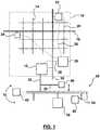
- Figure 1shows an energy system 10 having an electrolyser 12.
- the electrolyser 12is connected to an electrical grid 14 within a control area 16.
- the electrical grid 14is further connected to other electrical grid control areas through an interchange transmission line 18.
- the electrical grid 14is also made up of internal transmission lines 20 of varying capacities. Portions of the interchange transmission lines 18 within the control area 16 can also be considered to be internal transmission lines 20.
- the transmission lines 20are connected to generators 22 and loads 24.
- the electrolyser 12is also a load 24.
- a grid operator 26is responsible for maintaining a balance of power production and consumption within the control area 16 and, if necessary, for arranging for imports or exports of electricity from or to other control areas through the interchange transmission lines 18.
- the grid operator 26may have communication to varying degrees with one or more of the generators 22 and loads 24 through one or more communications links 28.
- the grid operatorhas control, to varying degrees, over at least some of the generators 22 and loads 24. Controlled generators 22 and loads 24 may be called assets.
- the communications link 28may, for example, allow the grid operator 26 to convey a dispatch order and to receive a message indicating acceptance, denial or modified acceptance of a dispatch order by the controlled asset 22, 24.
- the communications link 28may convey an electronic signal directly to an asset 22, 24 in a machine usable form.
- the communications link 28may be indirect, for example in the nature of a market offering of a dispatch order or service request, or an offer to provide electricity from a specified generator 22 or the grid 14 generally at a specified cost, price or time.
- the asset 22, 24may need to bid on, or contract for, the order, request or electricity and may receive confirmation of its obligation through an intermediary, such as a broker or automated auction system.
- Generators 22 or loads 24may operate essentially outside of the control of the grid operator 26.
- Uncontrolled generators 22 or loads 24are typically connected to the electrical grid through a meter which allows the grid operator 26 to at least know the production or consumption of generators 22 and loads 24 connected though the meter.
- the grid 14may take other forms.
- the grid 14may be contained within a control area 16 having no interconnections with other grids 14 or control areas 16.
- an electrolyser 12may be connected through a transmission line 20 more nearly directly to a generator 22.
- the functions of the grid operator 26could be simplified to the point where these functions are essentially automated.
- the grid operator 26may be a programmable logic controller, computer, or other programmable device rather than an agency or company employing people and using programmable devices.
- a load aggregatormay manage at least some aspects of the operation of multiple loads 24, including an electrolyser 12, and provide grid services based on the combined abilities of the multiple loads.
- the aggregatormay manage multiple electrolysers 12, or a mixture of one or more electrolysers 12 and one or more other loads 24.
- the load aggregatormay be a private company, or other entity separate from the grid operator 26, the load aggregator can be considered to be part of the grid operator 26 and the electrolyser operator.
- the grid operator 26balances the production and consumption of electricity in the control area 16 such that, among other things, the voltage in the grid 14 is generally stable. In addition, the amount of electricity carried by each transmission line 18, 20 must be kept below the maximum capacity of each transmission line 18, 20.
- the grid operator 26is responsible for managing both the balance of production and consumption and transmission constraints.
- the transmission constraintsmay be controlled by one or more other operators that coordinate with the grid operator 26. In this case, these other operators may be considered to be part of the grid operator 26.
- the grid operator 26may use the electrolyser 12 as a controllable load to aid in balancing or regulating the grid or to manage transmission constraints. For example, an excess of electricity produced in one area of the grid 14 can be consumed in the electrolyser 12 to prevent an over-voltage in the grid 14, to prevent electrical flow through a transmission line 18, 20 from exceeding its capacity, or both.
- the grid operator 26may also arrange transfers of electricity to or from other control areas 16 through an imbalance market or regulator.
- Grid operators 26typically try to avoid such transfers. This is because times when the grid operator 26 needs to import electricity tend to be times when imbalance energy is costly. Times when the grid operator 26 must export energy tend to be times when the price of electricity is low or even negative.
- the grid operator 26can use the electrolyser 12 to absorb energy that would otherwise need to be exported or that can be purchased from another control area at a negative price.
- the grid operator 26can also keep a generator 22 that is difficult or wasteful to throttle back in production to the extent that the electrolyser 12 can consume the electricity produced.
- Such use of the electrolyser 12may be by way of a dispatch order by the grid operator 26, or by way of a market offering.
- the energy system 10includes a natural gas system 30.
- the electrolyzer 12is connected to the natural gas system 30 through a hydrogen outlet 32.
- the natural gas system 30comprises pipelines 34 of varying capacities which carry natural gas from a natural gas supply 42 to gas consumers 40.
- Natural gas system 30may also comprise one or more reservoirs 36 for storing natural gas outside of the pipelines 34.
- the hydrogen outlet 32may be connected to a hydrogen pipeline 38 that carries hydrogen to a gas consumer 40 without passing through the natural gas system 30.
- the natural gas system 30is shown in Figure 1 to be apart from the control area 16 to simplify the Figure.
- the natural gas system 30 and control area 16are likely to overlap on the ground.
- gas consumer 40may also be either a load 24 or a generator 22 in the control area 16.
- Electrolyser 12receives electricity from a transmission line 20 and produces hydrogen, at least during some times. Some or all of the hydrogen may be injected from the hydrogen outlet 32 into a natural gas pipeline 34. In this way, electrolyser 12 stores energy in the energy system 10 by converting electrical energy into hydrogen and storing the hydrogen in the natural gas system 30. In some cases, the hydrogen may eventually be reconverted into electricity by being burned by a gas consumer 40 that is a natural gas fired generator 22. Converting electricity to hydrogen through an electrolyser 12 in one part of the control area 16 and generating corresponding electricity from a natural gas fired generator 22 in another part of the control area 16 provides a virtual transfer of electricity through the natural gas system 30.
- the hydrogendisplaces natural gas consumption and reduces the need to input natural gas into the natural gas system 30.
- the hydrogencan be deemed in a management, billing, tracking, tax, carbon offset, carbon credit or other system or process to have been burned at any time by any gas consumer 40.
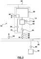
- FIG. 2shows further details of a portion of the energy system 10, particularly the connection between the electrolyser 12 and the natural gas system 30.
- the electrolyser 12 showncomprises a core 50, interim storage 52 and a compressor 54.
- Interim storage 52 and compressor 54are preferred but optional since some electrolysers 12 can be operated to output hydrogen at a pressure high enough to be injected into the natural gas system 30.
- direct connection between the core 50 and a natural gas pipeline 34 under conditions of variable power consumptionis likely to cause a high persistent pressure or pressure fluctuations in the electrolyser stacks. Both conditions increase the likelihood and magnitude of hydrogen leaks but can be avoided by producing hydrogen at less than pipeline pressure and providing a compressor 54.
- interim storage 52 and the compressor 54can be integrated into the balance of plant in the core 50.
- the interim storage 52 and compressor 54can be located outside of a building housing the electrolyser 12 or even in a remote location.
- the electrolyser core 50produces hydrogen at less than the pressure in a natural gas pipeline 34 of the natural gas system 30.
- the core 50may produce hydrogen at about 100 psig.
- Interim storage 52if provided, is intended primarily to aggregate produced hydrogen so that compressor 54 does not need to be operated as frequently or at a rate matching the rate of hydrogen production, and to provide a buffer against creating suction in the core 50.
- Compressor 54may be, for example, a positive displacement pump.
- a storage pressure gauge 66in fluid communication with the interim storage 52, monitors the pressure in the interim storage. Compressor 54 is turned on when the pressure gage 66 indicates that a high pressure set point has been reached. Compressor 54 is turned off when the pressure gage 66 indicates that a low pressure set point has been reached.
- a recycle loop 70 with a regulator valve 68may be added to prevent the compressor outlet pressure from exceeding a predetermined maximum.
- Hydrogen outlet 32feeds into the gas pipeline 34 through an output valve 56 and a gas meter 58.
- the output valve 56may be, for example, a back pressure regulator that opens only when the hydrogen pressure exceeds a minimum pressure selected to be above the likely maximum pressure in natural gas pipeline 34, for example 500 to 800 psig.
- the output valve 56may sense the actual pressure in the natural gas pipeline 34 electronically or pneumatically and adjust the minimum pressure to follow the pressure in the natural gas pipeline 34, plus a safety factor. This avoids excess hydrogen compression which consumes energy.
- the gas meter 58records the amount of hydrogen that flows into the gas pipeline for one or more billing or management uses.
- gas meters 58there may be two or more gas meters 58, one owned and used by the operator of the electrolyser 12 and one owned and used by the operator of the natural gas system 30.
- both of these operatorsmay be one company, or they may share date from a single gas meter 58.
- the gas meter 58may be read manually from time to time but preferably the gas meter 58 is capable of transmitting data, typically at regular polling intervals.
- the electrolyser core 50includes a water-hydrogen separator and a gas drier.
- a humidity sensor in the electrolyser 12checks that the hydrogen has been reduced to gas pipeline standards before it leaves the electrolyser 12.
- An oxygen sensorchecks to make sure that the hydrogen does not contain oxygen in excess of the electrolyser safety standards or the gas pipeline standards.
- the natural gas system operatormay require its own oxygen and humidity sensors near the point of entry into the gas pipeline 34.
- additivesmay be added to the hydrogen, for example anti-embrittlement additives to improve the compatibility of the hydrogen with materials in the natural gas system 30 or materials used by the gas consumer 40.
- Electrolyser 12has one or more controllers 60 that perform one or more control processes.
- the controller 60determines a maximum rate of hydrogen injection overtime and prevents the electrolyser 12 from injecting hydrogen at more than the maximum rate.
- the maximum ratemay be determined by a preselected maximum hydrogen concentration, for example 2% to 20% by volume, that applies to all components of the natural gas system. In this case, the maximum hydrogen concentration can not be exceeded in the natural gas pipeline 34 that receives the hydrogen. The rate of hydrogen injection at any time therefore can not exceed a maximum percentage of the natural gas flow rate in that natural gas pipeline 34 at that time.
- the controller 60receives a signal A from a natural gas pipeline flow meter 62 connected to the pipeline 34 and a signal B from the gas meter 58. Assuming that there are no upstream electrolyser 12 or the producer of hydrogen, the controller 60 compares the flow indicated by signal B to the flow indicated by signal A multiplied by the maximum percentage.
- the controller 60can be connected to a hydrogen sensor upstream of the hydrogen outlet 32 and further consider the hydrogen concentration in the gas pipeline 34 upstream of the hydrogen outlet 32.
- the controller 60may be connected to a hydrogen sensor downstream of the hydrogen outlet 32 to check directly whether the hydrogen concentration exceeds the maximum hydrogen concentration.
- the controller 60 or an electrolyser operatormay respond to information obtained from an entity that manages the natural gas system 30 indicating the natural gas flow rate in the gas pipeline 34 or indicating directly, or after further calculation, whether the natural gas system 30 can accept more hydrogen.
- a maximum rate of injectionthat is not limited by a single maximum hydrogen concentration that applies to all components of the natural gas system 30.
- the maximum rate of injectionmay consider, for example, dilution downstream of the gas pipeline 34 caused by a reservoir 36 or incoming flow of natural gas.
- a hydrogen pipeline 38may transport hydrogen directly to a reservoir 36 in which case whether further hydrogen injection is permitted may be determined by whether the hydrogen concentration in the reservoir 36 exceeds a selected maximum concentration.
- the controller 60compares the rate of hydrogen production, as indicated by gas meter 58 or an internal gas meter, to the maximum rate of injection continuously or at polling intervals. As long as the rate of hydrogen production remains below the maximum rate of injection, the rate of production can be determined by other factors. However, if the rate of hydrogen production exceeds the maximum rate of injection, then the controller 60 may send an alert to an operator or directly reduce the power consumption of the electrolyser 12, for example by way of a signal sent to a DC power supply within the electrolyser 12. Optionally, the controller 60 or the electrolyser operator may also send a signal to the grid operator 26 indicating that the electrolyser 12 is reducing its power consumption.
- the electrolyser 12is preferably sized relative to the typical flow in gas pipeline 34 such that the maximum hydrogen injection rate is rarely exceeded.
- a hydrogen pipeline 38may be used to connect the electrolyser 12 to a distant but larger gas pipeline 34 or directly to a reservoir 36.
- Any interim strorage 52may also be used to allow some hydrogen to be produced at some times at a rate exceeding the maximum injection rate.
- the controller 60may still need to reduce the net rate of hydrogen production at some times.
- the net rate of hydrogen productioncan be reduced by reducing the actual rate of hydrogen production or by venting some of the hydrogen that is produced to the atmosphere. While venting hydrogen is not desirable, the hydrogen recombines with vented or atmospheric oxygen to form water and does no material harm to the environment.
- Reducing the actual rate of hydrogen productiontypically requires reducing the rate of electricity consumption. While reducing electricity consumption is often acceptable, in some instances the electrolyser 12 may be under a contract or dispatch order to consume a predetermined amount of electricity, or the electrolyser 12 may be performing grid services. In these cases, an unplanned reduction in electricity consumption may harm the grid 14 or cause economic harm to the grid operator 26 or electrolyser operator. In these cases, the electrolyser operator may prefer to vent hydrogen.
- the controller 60, the electrolyser operator or another person or thingmay forecast the maximum injection rates expected to exist over a period of time.
- the forecastcan be based on one or more of current flow rate in the gas pipeline 34, a current trend in the flow rate through the gas pipeline 34, historical data, or information received from the natural gas system operator.
- the electrolyser 12is under some level of control by the grid operator 26, or is completely controlled by the grid operator 26, the forecast may be converted into an amount of available power consumption and provided to the grid operator 26.
- the electrolyser operator or controller 60may refuse or modify a dispatch order or request for grid services from the grid operator 26 based on the forecast.
- the electrolyser operatorcan bid on energy contracts based on the forecast.
- the electrolyser operatormay apply a factor of safety to the forecast, accept the possibility of hydrogen venting if the forecast is wrong, or even commit to a power consumption dispatch or contract that is forecasted to cause a need to vent hydrogen.
- Gas meter 58records the amount of hydrogen added to the pipeline 34.
- the operator of the natural gas system 30may pay the electrolyser operator for the hydrogen based on the meter 58 readings at a price fixed by contract or regulations.
- the hydrogenmixes with the natural gas and is thereafter considered to be natural gas.
- a consumer gas meter 64 between a pipeline 34 and a consumer 40may include a hydrogen concentration sensor.
- the meter 64, or a computer operated by the natural gas system operatormay adjust the actual gas flow rate to provide a flow rate of natural gas without hydrogen having an equivalent heating value for billing purposes.
- the natural gas system operatormay provide an adjustment to a set of consumers 40 downstream of the electrolyser 12 based on an estimated reduction in the heating value of gas flowing through meter 64 resulting from the hydrogen injected into the pipeline 34.
- An actual sale of hydrogenmay also be made to a gas consumer 40 by calculating the amount of hydrogen actually consumed by a customer using a calculated or measured flow rate and hydrogen concentration information.
- Hydrogencan also be sold to a consumer 40 through a hydrogen pipeline 38 or by way of tanker trucks.
- a virtual sale of hydrogencan be made to a consumer 40.
- the amount of gas withdrawn by various consumers 40is recorded by consumer gas meters 64. Some or all of the gas consumed by each consumer 40 in an aggregate amount less than or equal to the amount of hydrogen produced, as recorded by gas meter 58, is deemed to be hydrogen.
- the consumers 40pay the electrolyser operator or the natural gas system operator for the deemed hydrogen.
- the hydrogen production and deemed consumptionmay or may not balance in a given time period. If the production and deemed consumption are not the same, hydrogen is deemed to be stored or extracted from the natural gas system 30 during that time period.
- a hydrogen resellermay contract to buy hydrogen from the electrolyser operator and to sell hydrogen to consumers 40. Purchases by the hydrogen reseller are paid to the electrolyser operator and subtracted from the flow recorded through gas meter 58. Any remaining hydrogen may be sold to the natural gas system operator or other customers. A consumer 40 pays the hydrogen re-seller for some or all of the gas use indicated by use meter 64. The cost of any remaining gas used by the consumer 40 is paid to the natural gas system operator.
- a feemay also be paid to the natural gas system operator for transmitting or storing the hydrogen.
- the hydrogenmay be billed as hydrogen or as an equivalent amount, by heating value, of natural gas.
- the hydrogencan also be deemed to have been produced, or tagged, with attributes based on the source of the electricity used to produce it.
- an electrolyser 12may be connected only to a wind farm, solar facility or other specific generator 22.
- the electrolyser 12can be connected to a transmission line 20 between a generator 22 and the remainder of the grid 14.
- the hydrogencan be tagged as having been produced by the specific generator 22.
- the tagged hydrogencan be sold, in a real or virtual sale, under conditions considering the tag.
- a consumer 40may agree to pay a higher price for hydrogen tagged as being produced by a generator 22 operating from a renewable energy source such as wind, solar, biogas or syngas.
- a renewable energy sourcesuch as wind, solar, biogas or syngas.
- carbon credits or offsets, tax credits or other economic or regulatory attributes of renewable energymay be associated with the tagged hydrogen.
- Data relating to the production and use of the tagged hydrogenis collected in a computer and used to calculate an invoice for the sale of the tagged hydrogen or a record of the transfer of its other economic or regulatory attributes.
- the re-sellermay make a virtual purchase of only the tagged hydrogen.
- the attributes of the tagged hydrogenare transferred to the re-seller who may then transfer those attributes to a customer.
- the re-sellermay offer a virtual sale of hydrogen that has been produced only from renewable resources. This virtual sale might be satisfied with the delivery in fact of natural gas while the actual hydrogen displaces natural gas use elsewhere.
- the re-sellermay allow the customer to claim a carbon credit, tax credit, carbon offset or other benefit from having purchased the tagged hydrogen.
- the electrolyser 12is preferably connected to a high capacity transmission line 20.
- the electrolyser 12may be connected to, or near, an interchange transmission line 18. Since interchange transmission lines 18 are set up to allow electricity to be sold to another control area through an imbalance market, the grid 14 is configured to be able to route excess electricity to these lines 18.
- An electrolyser 12 positioned near an interchange line 18is in a location suitable for consuming excess power that the grid operator 26 would otherwise need to sell, often at negative pricing, in the imbalance market.
- Such an electrolyser 12is also positioned to allow a grid operator 26 to purchase, or approve a purchase, of incoming imbalance energy through an interchange line 18 without overloading internal transmission lines 20.
- the electrolyser 12may be operated primarily to provide grid services when the price of natural gas does not make converting electricity to natural gas profitable by itself. In this mode, hydrogen is produced and sold as a by-product of providing grid services but is not produced at other times. The electrolyser is off unless dispatched on, or unless electricity is offered at a very low rate during some particular period of time. The electrolyser 12 may be contracted to operate as required by the grid operator 26 or put under the direct control of the grid operator 26. When providing grid services having a time scale of 5 minutes or more, the grid operator 26 may communicate with an electrolyser operator by way of dispatch orders and confirmation messages.
- a dispatch ordermay be delivered by telephone, email or dedicated data link and specifies one or more desired rates of consumption during one or more future times periods.
- a confirmation messagedelivered by the same or another form of communication, indicates that the electrolyser 12 can and will consume power as specified in the dispatch order or indicates a portion of the dispatch order that the electrolyser 12 can comply with.
- information from a meter 84(see Figure 3 ) recording actual consumption by the electrolyser 12 is also sent to the grid operator 26.
- commands and confirmation messagesare sent directly between the grid operator 26 and the controller 60 of the electrolyser. These messages may be sent over a dedicated communication link 28.
- the market price for hydrogenmakes it profitable for the default condition of the electrolyser to be full power operation, at least while there is sufficient demand for the hydrogen.
- natural gasmust be imported by tanker or produced on the island and the price of natural gas is typically high.
- hydrogencan also be used to mix with propane to provide a blended gas with a WAUB index similar to natural gas.
- the electrolyser 12can provide grid services by way of being an interruptible load or being controlled for load destruction or apparent power production.
- FIG. 3shows various electrical components of the electrolyser 12.
- the electrolyser 12has a set of stack assemblies 80.
- Each stack assembly 80may in turn contain multiple electrolyser stacks.
- the stacksmay be, for example, alkaline or polymer electrolyte membrane (PEM) stacks.
- PEM stackas preferred since they are able to operate at near zero voltage, whereas alkaline stacks typically cannot operate below a significant percentage, for example 50%, of their maximum power consumption. PEM stacks also have a greater power density and tend to be designed to produce hydrogen at higher pressures.
- some alkaline stacks, such as those sold by Hydrogenics Corporationare designed to be self-pumping. This self-pumping feature can be useful when providing grid services since it avoids the need to frequently alter the speed of a water pump or flow control valve.
- the electrolyser 12Electrical power is provided to the electrolyser 12 from the grid 14 from a transmission line 18, 20 through an AC-AC step down transformer 82.
- the step down transformer 82reduces the voltage in the transmission line 18, 20 to the standard step-down voltage in the control area 16, for example 120 V or 220 V.
- Total power consumptionis tracked by a primary electrical meter 84.
- AC electricityis made available to the various components within the electrolyser 12 through a main bus 86.
- Each stack assembly 80is separately connected to the main bus 86 through an associated DC power supply 90 and stack sub-meter 88.
- the DC power supply 90should preferably have a wide voltage range, a large current capacity, and a durable variable output mechanism.
- One suitable power supplyis a Thyrobox H2TM power supply made by AEG Power Solutions. These power supplies have a DC output of between 1V DC and 400 V DC at up to 15,000 Amps and have Thyristor based variable output mechanisms.
- the Thyristor mechanismis a solid state device, which avoids moving parts that might otherwise wear out with rapid power changes continuing for long periods of time. Multiple power supplies may be provided to each stack assembly 80 if required to provide adequate power.
- the electrolyser 12also has a balance of plant 94, parts of which will be described further in relation to Figure 4 .
- Power for the balance of plant 94is provided from the main bus 86 through a balance of plant sub meter 92.
- the master controller 60When operating to provide grid services, for example frequency regulation, the master controller 60 attempts to operate the DC power supplies 90 such that the electrolyser 12 consumes a specified amount of power.
- the amount of powermay be specified by an operator considering a dispatch or market offering through communications link 28, or by direct control of the grid operator 26 through communications link 28.
- the controller 60may reduce the power consumed by the DC power supplies 90 by the amount of power required by the balance of plant 94. This amount of power may be estimated, for example as a percentage of the total specified power consumption, or determined by polling the balance of plant meter 92. The remaining power to be consumed is divided between the DC power supplies 90.
- Readings from stack sub-meters 88may be used in inner control or feedback loops to adjust the requested output from each power supply 90 such that the actual power consumed, as determined by a stack sub-meter 88, matches the intended portion of the specified power consumption. These inner loops may also operate in sub-controllers connected to each DC power supply 90 and its associated stack sub-meter 88.
- readings from the primary meter 84may be used in an outer control or feedback loop to adjust control signals such that the total power consumed by the electrolyser 12, as determined by primary meter 84, matches the specified amount.
- the grid operator 26may send a series dispatches, each dispatch indicating the required power consumption for a specified period of time.
- the controller 60attempts to match the dispatches with the timing and amount of actual power consumption as closely as possible or at least within a range of tolerance, for example within 10% of the specified power consumption for at least 90% of the applicable time period.
- An acceptable tolerance for following the dispatchesmay be specified by the grid operator 26 directly or by way of a penalty for operation outside of the stated tolerance.
- the controller 60may be programmed to implement a number of modes of operation.
- the controller 60selects between modes of operation at the request or control of an operator, or as a programmed response to a specified grid service commitment or to forecasted or contracted future power consumption or price.
- the electrolyser 12may provide grid stabilizing services, for example primary or secondary frequency regulation services, in which the specified power consumption is expected to vary over a time period of 5 cycles to 5 or 10 minutes, or over longer periods of time but in an unpredictable manner.
- the specified power consumptionmay vary every 4 seconds, which is the time between automatic generation control (AGC) signals in some North American grids 14.
- AGCautomatic generation control
- the specified power consumptionmay vary every 5 to 10 minutes.
- the controller 60operates all of the stack assemblies 80 at about the same power level. In this way, the total size of a power fluctuation is spread out over the maximum number of stack assemblies 80 to provide the minimum rate of change in each stack assembly 80.
- Any excess stack assemblies 80may be shut down or put in standby. For example, for a 1 MW electrolyser 12 having five stack assemblies 80, a contract to provide 0.5 MW of primary frequency regulation is met by operating three stack assemblies 80 at about the same power level as required to satisfy the contract. The two remaining stack assemblies 80 as shut down or put on standby. However, these two remaining stack assemblies may be activated if an opportunity arises to purchase electricity at a price low enough to profit from producing additional hydrogen.
- the specified power consumptionis expected to vary over a time period of 5 to 30 minutes, for example 5 to 10 minutes for secondary regulation and 15 to 30 minutes for tertiary regulation.
- the maximum size of the variation over a period of timemay also be predictable.
- the controller 60determines a number of stack assemblies 80 required to produce a nominal base line consumption, being the minimum consumption expected over a frequency regulation period, which can be some or all of the time covered by a grid services contract, and operates these stack assemblies 80 at full power.
- the controlleralso predicts a second number of stack assemblies 80 sufficient to provide additional consumption expected during the frequency regulation period, and operates these stack assemblies 80 with variable power consumption.
- a 1 MW electrolyser 12may have five stack assemblies 80.
- the electrolyser 12can provide up to 0.2 MW of active frequency regulation from one stack assembly 80 while also consuming between 0 and 0.8 MW of base line consumption in the four remaining stack assemblies 80. While consuming 1 MW, all stack assemblies 80 are in operation. If the required base line consumption is reduced to 0.6 MW, then one stack assembly 80 can be shut down or put into a standby mode, or operated to provide active frequency regulation. When providing base line consumption, it is preferable to have shut down or put into standby as many stack assemblies 80 as possible rather than spreading the base line consumption over all stack assemblies 80 not needed for active frequency regulation.
- the electrolyser 12is operated to provide a hydrogen production or energy arbitrage mode.
- all stack assemblies 80operate at full power.
- a potential profit from producing hydrogencan be compared to profit from providing a grid service.
- the expected profit from providing grid servicescan be increased by an estimated value of the hydrogen that will be produced while providing the grid service.
- a sufficient portion of the electrolyser capacityis allocated to providing the grid service. Any remaining stack assemblies 80 can be operated in hydrogen production or arbitrage mode.
- the controller 60may also be programmed to start and stop the one or more stack assemblies 80 such that the one or more stack assemblies 80 are on while electricity is available at or below a specified price.
- the controller 60may be linked to a grid voltage meter 96 or other grid condition sensor. If the grid voltage is rising or high, the controller 60 increases power consumption until the maximum power consumption is reached or the grid voltage stabilizes within a target range. Conversely, if the grid voltage is dropping or low, the controller 60 decreases power consumption until the grid voltage stabilizes within the target range.
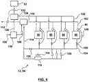
- FIG. 4shows various elements of the balance of plant 94 of the electrolyser 12.
- Each stack assembly 80has a thermostat 90 located in the stack assembly 80 or in an oxygen outlet 102.
- the thermostat 90is connected to a flow control valve 100 in a water input line 104 leading to the stack assembly 80.
- a stack temperature controller 106or another controller such as the master controller 60, modulates the flow control valve 100 to maintain the temperature of the stack assembly within a specified range.
- the flow of wateris provided from a set of parallel pumps 108.
- the number of pumps 108is one more than the number required to provide the maximum design water flow such that a pump 108 may be removed for servicing.
- Excess cooling wateris produced with the oxygen and travels from the oxygen outlet 102 to an oxygen separator 110.
- the pressure within the oxygen separator 110is maintained at a generally constant level by an oxygen regulator 112.
- the separated water 114returns to the pumps 108 through a cooling device, such as a radiator 116 and fan 118.
- the speed of the fan 118is controlled to produce a desired temperature in the water reaching the pumps 108.
- a recirculation valve 120is modulated in response to the current drawn by pumps 108 to allow water recirculation in the event that closing flow control valves 100 are stressing the pumps 108. While the speed of the pumps 108, or the number of pumps 108 operating, may also be reduced, repeatedly varying the speed of the pumps 108 causes them to wear rapidly.
- Hydrogenis produced from a hydrogen outlet 122 of each stack assembly and travels to a hydrogen separator 124. Separated water 126 flows to a make up water tank 128. Make up water tank 128 also receives deionized make up water 130 when required. A pump 108 pumps make up water into the water recirculation circuit when the water level in the oxygen separator 110 drops to a specified minimum.
- the pressure in the hydrogen separator 124is determined by a hydrogen regulator 132. Produced hydrogen is collected in the interim storage tank 52. The pressure in the interim storage tank 52 is always less than the pressure in the hydrogen separator 124. However, referring back to Figure 2 , a compressor 54 is operated such that pressure in the interim storage tank is not drawn down to less than a specified part, for example 80%, of the gauge pressure in the hydrogen separator 124 to reduce losses in pressure energy. Oxygen leaving the electrolyser 12 may pass through a pressure recovery turbine or other device to recover its pressure energy.
- the seals in the stack assemblies 80may wear out due to the product of the pressure applied against them over time, and due to the fluctuations in the pressure applied against them.
- the electrolyser 12is used to provide grid services, the power applied to the stack fluctuates frequently and it is beneficial to avoid corresponding fluctuations in pressure.
- Pressure against the sealsis kept more generally constant by venting multiple stack assemblies 80 to common gas separation vessels 124, 110.
- the pressure regulators 112, 132are able to provide stable pressures in the gas separation vessels 124, 110 while permitting flow through the stack assemblies 80. Variations in the gas produced by one stack assembly 80 are dampened by the size of the gas separation vessels 124, 110.
- the system as a wholetherefore requires fewer pressure regulating devices, and the pressure regulating devices can have reduced movement, relative to a plant having gas separation vessels for each stack assembly. Pressure following between the oxygen regulator 112 and the hydrogen regulator 132 maintains almost equal pressures on both sides of the membranes of the stack assemblies 80.
- the gas outlets of the stacksare located on the top of the stacks and water flows upwards through the stacks.
- a stackWhen a stack is powered down, its residual gas bubbles flow upwards to the gas separators 110, 124. Water drains down from the gas separators 110, 124 into the stack assemblies 80.
- the water in the stacksprevents residual hydrogen and oxygen from reacting and either degrading the materials, for example the catalysts, in the stack or converting the stack into a fuel cell.
- the wateralso preserves the pressure in the stack to reduce pressure fluctuations. In this way, power can be reduced to a stack without requiring other changes in the balance of plant.
- a consumer 40may extract gas from the pipeline 34 through a hydrogen enriching extraction device 134.
- Multiple meters 64allow the amount of gas withdrawn from the pipeline 34, returned to the pipeline 34, and delivered to the consumer 40 to be measured.
- Isolation valves 136optionally allow the extraction device 134 to be operated in a batch mode.
- a compressor 138allows hydrogen depleted gas to be returned to the pipeline 34.
- the consumer 40may be, for example, a natural gas fuelling station or a natural gas fired electrical generating station.
- a variable low concentration, for example up to about 5%, of hydrogencan be added to natural gas without materially changing the operation of typical gas fired appliances such as a household furnace. Engines, however, can be more sensitive to changes in the composition of their fuel. Natural gas engines include gas fired turbines used to generate electricity and internal combustion engines in vehicles. However, a moderate concentration of hydrogen, up to about 15%, can be beneficial to the operation of a natural gas engine and can reduce emissions of carbon dioxide and pollutants.
- the control system of a natural gas enginemay sense the hydrogen concentration of the fuel, the operation of the engine in response to the hydrogen content of the fuel, or both, and react accordingly.
- natural gasmay be provided enriched with hydrogen in one or more grades of generally constant concentrations greater than what is present in the pipeline 34.
- a 5% or 10% hydrogen enriched natural gas productcan be produced by measuring the concentration of hydrogen in natural gas withdrawn from the pipeline 34 and adding a required amount of hydrogen to reach the desired concentration.
- the desired amount of hydrogencan be determined by monitoring a hydrogen concentration sensor in addition to, or instead of, pre-calculating the required amount. In this case, measuring the concentration of hydrogen in natural gas withdrawn from the pipeline 34 can be omitted.
- the additional hydrogencan be provided by hydrogen pipeline 38, tanker truck, on site electrolysis, or on site conversion of natural gas, for example by steam reformation.
- the electrolyser 12may also be co-located with a fuelling station or electrical generating station, or connected by a hydrogen pipeline 38, to provide hydrogen for natural gas enriching directly.
- a mixture having an increased or decreased concentration of hydrogencan be extracted from the pipeline 34 through the extraction device 134. If the extracted mixture has more than the desired hydrogen concentration, the hydrogen can be diluted to the target concentration with non-enriched gas taken from the pipeline 34.
- the extraction device 134can remove hydrogen enriched gas for example by a hydrogen selective membrane such as a membrane made of palladium or a palladium silver alloy.
- the pipeline gascan also be compressed to separate the gasses by liquefying only one of them.
- Hydrogen enriched natural gasmay also be withdrawn by an absorbent in the extraction device 134.
- the absorbentmay be a metal hydride forming metal such as lanthium nickel or iron-titanium or carbon nanotubes.
- the extraction device 134is a tank filed with the absorbent. By operating valves 136 and compressor 138, pipeline gas is passed through the tank at pipeline pressure, which causes hydrogen to be captured as a metal hydride. The tank is then isolated from the pipeline 34 and vented to the consumer 40. When pressure in the extraction device 134 is reduced, adsorbed hydrogen is also released creating a hydrogen enriched natural gas.
- the amount of hydrogen removed by the fuelling station or electricity generating plantmay be monitored for billing separately from the natural gas.
- the hydrogen, or hydrogen enriched natural gasmay carry a different price, a carbon credit or renewable energy benefit.
- the fuelling stationmay pass on this benefit to the customer, or offer the customer the option of purchasing a lower emissions or partially renewable fuel.
- the operation of two or more electrolysers 12may be controlled together as a fleet.
- a fleet controllermay operate an electrolyser 12 that is subject to fewer electrical transmission restraints, is subject to fewer restraints on the amount of hydrogen that can be injected to a pipeline, or is better able to serve a market for a higher value hydrogen use.
- hydrogenmay be used or injected into a pipeline indirectly.
- the hydrogenmay be input into a process to create methane.
- the methanemay then be injected into a gas pipeline or supplied to a vehicle fuelling station or electrical generating station.
- Hydrogencan be converted into methane by, for example, a Sabatier process.
- the Sabatier processrequires a source of carbon dioxide.
- the carbon dioxidecan be extracted from the exhaust from an engine or furnace, from biogas, or from another carbon sequestration processes.
- hydrogencan be converted into methane by adding the hydrogen to an anaerobic digester, for example a digester being used to produce methane from biomass.
- the hydrogenis combined with carbon dioxide in the digester to create methane and increase the methane output of the digester.
- the hydrogenmay be combined outside of the digester with carbon dioxide separates from biogas produced by an anaerobic digester.
- Converting the hydrogen to methaneconsumes about 20% of the potential energy of the hydrogen. However, some of this loss may be recovered as waste heat. Further, methane may be injected in unlimited amounts into a natural gas pipeline. Methane also has about three times the energy density of hydrogen and is the primary fuel of existing natural gas fuelled vehicles. Accordingly, in some cases the conversion to methane may be desirable. In particular, if the cost of producing the hydrogen is at least partially covered by providing grid services, if the consumption of carbon dioxide in the methanation process provides a benefit such as a carbon credit, or if the hydrogen or the electricity used to produce the hydrogen would otherwise have been wasted, then producing methane can be a viable use for the hydrogen.
Landscapes
- Chemical & Material Sciences (AREA)
- Engineering & Computer Science (AREA)
- Business, Economics & Management (AREA)
- Organic Chemistry (AREA)
- Metallurgy (AREA)
- Materials Engineering (AREA)
- Electrochemistry (AREA)
- Chemical Kinetics & Catalysis (AREA)
- Economics (AREA)
- Health & Medical Sciences (AREA)
- Marketing (AREA)
- Physics & Mathematics (AREA)
- General Business, Economics & Management (AREA)
- General Physics & Mathematics (AREA)
- Theoretical Computer Science (AREA)
- Strategic Management (AREA)
- Power Engineering (AREA)
- Development Economics (AREA)
- Automation & Control Theory (AREA)
- Inorganic Chemistry (AREA)
- Tourism & Hospitality (AREA)
- Human Resources & Organizations (AREA)
- General Health & Medical Sciences (AREA)
- Water Supply & Treatment (AREA)
- Public Health (AREA)
- Primary Health Care (AREA)
- Finance (AREA)
- Accounting & Taxation (AREA)
- Management, Administration, Business Operations System, And Electronic Commerce (AREA)
- Electrolytic Production Of Non-Metals, Compounds, Apparatuses Therefor (AREA)
- Supply And Distribution Of Alternating Current (AREA)
- Vehicle Body Suspensions (AREA)
- Electrical Discharge Machining, Electrochemical Machining, And Combined Machining (AREA)
- Crystals, And After-Treatments Of Crystals (AREA)
Description
- This specification relates to electrolysers and methods of operating electrolysers in an energy system, for example to produce hydrogen for energy storage or fuel, or to provide electrical grid services.
DE 10 2004 030717 A1 describes a method and a device with which geothermal energy is converted and stored when there is an abundance and reconverted to usable energy in times when the readily available geothermal energy is insufficient. InDE 10 2010 020762 A1 a method is described whereby renewable energy is transferred from electric energy by means of electrolysis to hydrogen as a secondary energy carrier, which is then fed into a natural gas pipeline, mixed with natural gas and transported as a gas mixture to the consumption point. The composition ratio of the gas mixture is determined and can be controlled to ensure a constant energy output at the user location. A similar method is described inWO 2005/071815 A1 andWO 2011/144198 A1 .European Patent EP 1 177 154 B1 describes an energy distribution network for providing an amount of hydrogen required from an electrolyser by a user. The network comprises an electrical energy source, an electrolyser and a controller. The controller receives and processes control inputs including data pertaining to a demand for hydrogen by a user. The controller is connected to the electrolyser and controls the generation of hydrogen by the electrolyzer based at least in part on the control inputs.- Canadian Patent
CA 2 511 632 C describes an energy network having a plurality of power stations and a plurality of loads interconnected by an electricity grid. The loads may include electrolysers. The network has a controller that is connected to the stations and the loads. The controller is operable to vary the available power from the power stations or to adjust the demands from the electrolysers to provide a desired match of availability with demand. Hydrogen may be produced as a transportation fuel with specific verifiable emission characteristics. - The following discussion is intended to introduce the reader to the detailed description to follow, and not to limit the invention, which is defined according to the appended claims .
- An electrolyser operates within an energy system, for example to provide grid services, energy storage or fuel, or to produce hydrogen from electricity produced from renewable resources. The electrolyser is configured to operate at frequently or quickly varying rates of electricity consumption or to operate at a specified power consumption.
- The process has steps of providing an electrolyser and receiving a series of dispatches indicating a specified power consumption for a period of time. The dispatches occur at least once every 30 minutes. The electrolyser is operated according to the dispatches. Hydrogen produced by the electrolyser while operating according to the dispatches is discharged to a natural gas system.
- In some cases, an energy system has an electrical grid, an electrolyser and a natural gas system. The electrolyser is operated to provide a grid service and discharges hydrogen into the natural gas system.
- In some cases, a process has steps of providing an electrolyser, operating the electrolyser according to a dispatch order from an electrical grid operator or according to a grid services contract and discharging the hydrogen produced while so operating to a natural gas pipeline.
- The method of storing excess electrical energy in a grid has steps of converting the excess energy into hydrogen and injecting the hydrogen into a natural gas system.
- In some cases, a method of making a virtual transfer of electricity has steps of consuming electricity through an electrolyser operating at a first location within an electrical grid to produce hydrogen, injecting the hydrogen into a natural gas system at a first location, extracting natural gas from the natural gas system at a second location, burning the natural gas to produce electricity, and supplying the produced electricity to a second location within the electrical grid.
- In some cases, a method of marketing a virtual sale of hydrogen has steps of consuming electricity through an electrolyser to produce hydrogen, injecting the hydrogen into a natural gas system, measuring the amount of hydrogen injected into the natural gas system, measuring an amount of natural gas withdrawn from the natural gas system by a customer and invoicing the customer for an amount of hydrogen consumption equivalent to at least a portion of the amount of natural gas withdrawn. Optionally, the electricity may comprise electricity actually produced or deemed to have been produced from a renewable resource.
- The electrolyser has multiple stack assemblies each having a separate power supply and a controller adapted to operate the multiple stack assemblies at different rates of power consumption at the same time.
- In some cases, an electrolyser has multiple stack assemblies that vent upwards to shared gas separators.
- In some cases, an electrolyser has a controller and an electricity meter. The controller is adapted to operate a DC power supply so as to consume electricity at a pre-determined rate. Optionally, the controller may operate the DC power supply so as to consume electricity at a pre-determined rate when electricity is available at or below a predetermined price.
- In some cases, a method of operating an electrical grid has steps of importing imbalance energy and consuming the imbalance energy through an electrolyzer connected to a natural gas system.
- In some cases, a method of operating an electrical grid has steps of operating a generator to produce electricity in excess of an amount required to operate a grid and consuming the excess electricity in an electrolyser connected to a natural gas system. There may be a further step of comparing the marginal cost of the excess electricity less any cost of not producing the excess electricity to a market value of the hydrogen.
- In some cases, a process has steps of consuming electricity through an electrolyser during a first period of time to produce hydrogen and injecting the hydrogen into a natural gas system and, during a second time period, burning natural gas to produce electricity.
- In some cases, a natural gas system has a customer gas meter comprising a hydrogen concentration sensor. Data relating to flow rate and hydrogen concentration is converted into an equivalent flow rate of natural gas.
- In some cases, a method of operating a natural gas fuelling station or natural gas fired electrical generating station has steps of measuring the concentration of hydrogen in natural gas withdrawn from a pipeline and adding hydrogen to produce a gas mixture with a specified hydrogen concentration.
- In some cases, a method of operating a natural gas fuelling station or natural gas fired electrical generating station has steps of enriching a mixture of hydrogen and natural gas withdrawn from a pipeline and adding natural gas to produce a gas mixture with a specified hydrogen concentration.
- In some cases, a method of operating an electrolyser has steps of receiving data related to a maximum amount of hydrogen that may be injected into a gas pipeline and a) controlling the electrolyser to consume no more than an amount of electricity that will produce the maximum amount of hydrogen, b) venting excess hydrogen or c) sending a signal to a grid operator indicating a corresponding maximum amount of hydrogen that can be produced. The data may include the flow rate of natural gas in the pipeline.
- The elements and steps described in the cases above may be used in the combinations described in the cases, in a combination of any one of the cases described above with any element or step found in another case or in the detailed description to follow, or in other combinations.
Figure 1 is a schematic representation of an energy system comprising an electrolyser.Figure 2 is a schematic representation of a portion of the energy system ofFigure 1 including a connection between the electrolyser and a gas pipeline.Figure 3 is a schematic representation of various electrical components of the electrolyser ofFigure 1 .Figure 4 is a schematic representation of hydraulic and gas circuits of the electrolyser ofFigure 1 .Figure 5 is a schematic representation of an optional hydrogen enriched gas withdrawal system for the energy system ofFigure 1 .- Water electrolysis, called electrolysis in this specification, converts electrical energy into chemical energy in the form of hydrogen. The hydrogen is most valuable when consumed as an essentially pure fuel or industrial chemical. However, the hydrogen also has value when blended with other gasses, the value tending to decline roughly with hydrogen concentration. The hydrogen can also be converted back into electricity. Further, in some situations the ability of an electrolyser to consume power can provide a valuable service, for example helping to balance or regulate an interconnected transmission system, also called an electrical grid. Hydrogen can be considered as a fuel or industrial chemical, but can also be seen as an energy storage or transporting medium. An electrolyser can be considered as a device for producing hydrogen, and also as a device for providing electrical grid services.
- Grid services, which may also be called ancillary services or reserves, include various services that help maintain reliable operation of a grid. A grid system operator, sometimes call an independent system operator (ISO), electric system operator
- (ESO) or transmission system operator (TSO), may offer contracts for various kinds of grid services. Grid services include operations that assist an electrical grid operator in managing a control area, or that can be used to either reduce or facilitate energy transfers between control areas. Of particular interest herein, some grid service contracts require the owner of a variable load to respond to dispatch orders made by a grid system operator for the purpose of balancing total production and consumption on the grid, for example to avert or correct a short term imbalance. Electrical generators and controllable loads are both considered to be assets of the grid that can potentially provide grid services. The most significant loads in a grid tend to be industrial processes. However, industrial processes tend to operate most efficiently at steady states and so only some industrial processes may be used to provide grid services, and the potential value of their grid services is typically small.
- In order to provide grid services, a process is required to operate at least with a variable rate of power consumption. The potential value of the grid services that can be provided by a variable load are increased a) if the rate, frequency, or size of the potential change in power consumption is increased, b) if the process is able to operate accurately at a specified rate of power consumption or c) if the process can be controlled by the grid operator.
- The rate, frequency and size of a change in power consumption is relevant to the value of grid services because very few loads or power generating assets are able to alter their consumption or production quickly, frequently or by a large amount. Renewable energy generating assets such as solar panels or wind turbines fluctuate more frequently and rapidly, and to a greater extent, than conventional generating assets. Integrating high levels of renewable energy generating assets in a grid therefore requires a corresponding increase in the ability to alter other assets frequently and quickly, and to a corresponding degree.
- The ability to operate accurately at a specified rate of power consumption is valuable since a load that can follow dispatch orders precisely helps provide faster and simpler resolution of imbalances than a less precise asset. In market based systems, reduced costs may only apply to a specified consumption.
- Enhanced control by the grid operator would increase the range of problems that can be solved by a controllable load. For example, power to an ordinary interruptible load can be cut to prevent voltage in the grid from declining below a minimum in an emergency but then the grid operator does not have precise control over when the load will return. It would be of greater value to the grid operator if the duration of a load interruption was also controllable, and if the load could also be used to prevent an over-voltage in the grid. The value is higher if the grid operator's dispatch is essentially mandatory or almost always followed, rather than being subject to acceptance by the asset owner. Actual control, wherein the grid operator can send a control signal to the load controller rather than a dispatch order to a load operator, also provides enhanced value. Variable control, wherein the grid operator can dispatch an order or send a control signal specifying a desired rate of power consumption, provides more value than the mere ability to completely shut down a load.
- A process is useful if it can provide any one or more of the advantages described above, but many of them are difficult to provide. Regarding the rate, frequency and magnitude of changes in power consumption, most industrial processes are constrained in their ability to respond to a requested change by one or more of a limited range of efficient process operation, mechanical components used in the process, and the need to produce a product. The mechanical components wear out or fail more frequently when they are not operated in steady states. The rate of product production may need to satisfy physical or market constraints. Regarding the ability to operate at a specified rate of power consumption, most industrial processes are controlled by specifying a production rate, not by specifying power consumption. Regarding control by the grid operator, this interferes with the industrial manager's ability to optimize their process according to other constraints.
- In order to increase its potential to provide grid services, an electrolyser is preferably configured to have one or more of the ability to operate at frequently, quickly or widely variable rates or electricity consumption, to operate at a specified rate of power consumption, and to permit control by a grid operator.
- One or more of these attributes can also be useful when not providing services to a typical large operating authority controlled grid. For example, in order to produce hydrogen from renewable energy, an electrolyser may be connected directly, or in a microgrid, to an electrical generator. The generator may comprise, for example, a wind turbine, a solar panel, a thermal solar device, or a generator burning biogas. In such a direct or minimally buffered system, the need for electrical energy storage can be reduced to the extent that the electrolyser can operate with whatever amount of power is being produced in real time.
- In another example, an electrolyser may be connected to an electrical grid that allows for direct contracts between energy generators or loads, or that provides an auction or other market for dispatch orders or service requests from the grid operator. In these situations, a contracted low electricity price may apply only to a specified time and amount of energy purchased. Any discrepancy between the contracted and actual time or amount of electricity consumed is likely to result in an increased payment by the electrolyser operator. Since contracts may specify an electricity purchase at a rate varying in a step wise manner over time, electricity costs are minimized if the electrolyser can follow the specified steps accurately. This requires rapid changes between precisely specified consumption rates. Further, in systems where energy purchases can be verified or designated as coming from a renewable or low greenhouse gas generating source, claiming credits, offsets or other benefits may require a high level of correspondence between data relating to renewable energy production or purchase and data documenting actual electricity used.
- The presence of a strong market for essentially pure hydrogen, or at least hydrogen at a higher concentration, may require balancing production restraints with the value of providing grid services. On the other hand, when the market for pure or high concentration hydrogen has been satisfied, or is likely to be satisfied incidentally by the provision of grid services, then providing grid services may be more valuable that providing any specific amount of further hydrogen production. Connecting the electrolyser to a natural gas system provides a market, and a physical storage and transportation system, capable of accepting essentially any quantity of hydrogen that might be produced by the electrolyser at essentially any time. The electrolyser can then be controlled to provide grid services of the highest value essentially without concern for the timing or amount of hydrogen production.
- The further description to follow describes an energy system having an electrical grid, an electrolyser and a natural gas system. Some hydrogen produced by the electrolyser may be used for higher value markets, but hydrogen may also be injected into the natural gas system. The design of the electrolyser facilitates operating in a manner that provides grid services. The system facilitates extracting value from the hydrogen injected into the natural gas system.
Figure 1 shows anenergy system 10 having anelectrolyser 12. Theelectrolyser 12 is connected to anelectrical grid 14 within acontrol area 16. Theelectrical grid 14 is further connected to other electrical grid control areas through aninterchange transmission line 18. Within thecontrol area 16, theelectrical grid 14 is also made up ofinternal transmission lines 20 of varying capacities. Portions of theinterchange transmission lines 18 within thecontrol area 16 can also be considered to beinternal transmission lines 20.- The
transmission lines 20 are connected togenerators 22 and loads 24. Theelectrolyser 12 is also aload 24. Agrid operator 26 is responsible for maintaining a balance of power production and consumption within thecontrol area 16 and, if necessary, for arranging for imports or exports of electricity from or to other control areas through theinterchange transmission lines 18. Thegrid operator 26 may have communication to varying degrees with one or more of thegenerators 22 and loads 24 through one or more communications links 28. The grid operator has control, to varying degrees, over at least some of thegenerators 22 and loads 24.Controlled generators 22 and loads 24 may be called assets. - The communications link 28 may, for example, allow the
grid operator 26 to convey a dispatch order and to receive a message indicating acceptance, denial or modified acceptance of a dispatch order by the controlledasset asset generator 22 or thegrid 14 generally at a specified cost, price or time. Theasset Other generators 22 or loads 24 may operate essentially outside of the control of thegrid operator 26.Uncontrolled generators 22 or loads 24 are typically connected to the electrical grid through a meter which allows thegrid operator 26 to at least know the production or consumption ofgenerators 22 and loads 24 connected though the meter.- Alternatively, the
grid 14 may take other forms. For example, in a remote community thegrid 14 may be contained within acontrol area 16 having no interconnections withother grids 14 orcontrol areas 16. In a captive or privately owned electrical system, or part of an electrical system, anelectrolyser 12 may be connected through atransmission line 20 more nearly directly to agenerator 22. In both of these cases, the functions of thegrid operator 26 could be simplified to the point where these functions are essentially automated. Thegrid operator 26 may be a programmable logic controller, computer, or other programmable device rather than an agency or company employing people and using programmable devices. - In another alternative, a load aggregator may manage at least some aspects of the operation of
multiple loads 24, including anelectrolyser 12, and provide grid services based on the combined abilities of the multiple loads. The aggregator may managemultiple electrolysers 12, or a mixture of one ormore electrolysers 12 and one or more other loads 24. In this case, although the load aggregator may be a private company, or other entity separate from thegrid operator 26, the load aggregator can be considered to be part of thegrid operator 26 and the electrolyser operator. - The
grid operator 26 balances the production and consumption of electricity in thecontrol area 16 such that, among other things, the voltage in thegrid 14 is generally stable. In addition, the amount of electricity carried by eachtransmission line transmission line Figure 1 , thegrid operator 26 is responsible for managing both the balance of production and consumption and transmission constraints. Optionally, the transmission constraints may be controlled by one or more other operators that coordinate with thegrid operator 26. In this case, these other operators may be considered to be part of thegrid operator 26. Thegrid operator 26 may use theelectrolyser 12 as a controllable load to aid in balancing or regulating the grid or to manage transmission constraints. For example, an excess of electricity produced in one area of thegrid 14 can be consumed in theelectrolyser 12 to prevent an over-voltage in thegrid 14, to prevent electrical flow through atransmission line - The
grid operator 26 may also arrange transfers of electricity to or fromother control areas 16 through an imbalance market or regulator.Grid operators 26 typically try to avoid such transfers. This is because times when thegrid operator 26 needs to import electricity tend to be times when imbalance energy is costly. Times when thegrid operator 26 must export energy tend to be times when the price of electricity is low or even negative. - The
grid operator 26 can use theelectrolyser 12 to absorb energy that would otherwise need to be exported or that can be purchased from another control area at a negative price. Thegrid operator 26 can also keep agenerator 22 that is difficult or wasteful to throttle back in production to the extent that theelectrolyser 12 can consume the electricity produced. Such use of theelectrolyser 12 may be by way of a dispatch order by thegrid operator 26, or by way of a market offering. - The
energy system 10 includes anatural gas system 30. Theelectrolyzer 12 is connected to thenatural gas system 30 through ahydrogen outlet 32. Thenatural gas system 30 comprisespipelines 34 of varying capacities which carry natural gas from anatural gas supply 42 togas consumers 40.Natural gas system 30 may also comprise one ormore reservoirs 36 for storing natural gas outside of thepipelines 34. Optionally, thehydrogen outlet 32 may be connected to a hydrogen pipeline 38 that carries hydrogen to agas consumer 40 without passing through thenatural gas system 30. Thenatural gas system 30 is shown inFigure 1 to be apart from thecontrol area 16 to simplify the Figure. Thenatural gas system 30 andcontrol area 16 are likely to overlap on the ground. In particular,gas consumer 40 may also be either aload 24 or agenerator 22 in thecontrol area 16. Electrolyser 12 receives electricity from atransmission line 20 and produces hydrogen, at least during some times. Some or all of the hydrogen may be injected from thehydrogen outlet 32 into anatural gas pipeline 34. In this way, electrolyser 12 stores energy in theenergy system 10 by converting electrical energy into hydrogen and storing the hydrogen in thenatural gas system 30. In some cases, the hydrogen may eventually be reconverted into electricity by being burned by agas consumer 40 that is a natural gas firedgenerator 22. Converting electricity to hydrogen through anelectrolyser 12 in one part of thecontrol area 16 and generating corresponding electricity from a natural gas firedgenerator 22 in another part of thecontrol area 16 provides a virtual transfer of electricity through thenatural gas system 30.- Regardless of whether or when the hydrogen actually reaches a natural gas fired
generator 22 or not, the hydrogen displaces natural gas consumption and reduces the need to input natural gas into thenatural gas system 30. The hydrogen can be deemed in a management, billing, tracking, tax, carbon offset, carbon credit or other system or process to have been burned at any time by anygas consumer 40. Figure 2 shows further details of a portion of theenergy system 10, particularly the connection between theelectrolyser 12 and thenatural gas system 30. Theelectrolyser 12 shown comprises a core 50,interim storage 52 and acompressor 54.Interim storage 52 andcompressor 54 are preferred but optional since someelectrolysers 12 can be operated to output hydrogen at a pressure high enough to be injected into thenatural gas system 30. However, direct connection between the core 50 and anatural gas pipeline 34 under conditions of variable power consumption is likely to cause a high persistent pressure or pressure fluctuations in the electrolyser stacks. Both conditions increase the likelihood and magnitude of hydrogen leaks but can be avoided by producing hydrogen at less than pipeline pressure and providing acompressor 54.- The division of components shown in
Figure 2 between the core 50, the remainder of theelectrolyser 12, and the area outside of theelectrolyser 12 is arbitrary. For example,interim storage 52 and thecompressor 54 can be integrated into the balance of plant in thecore 50. Alternatively, theinterim storage 52 andcompressor 54 can be located outside of a building housing theelectrolyser 12 or even in a remote location. - In
Figure 2 , theelectrolyser core 50 produces hydrogen at less than the pressure in anatural gas pipeline 34 of thenatural gas system 30. For example, thecore 50 may produce hydrogen at about 100 psig.Interim storage 52, if provided, is intended primarily to aggregate produced hydrogen so thatcompressor 54 does not need to be operated as frequently or at a rate matching the rate of hydrogen production, and to provide a buffer against creating suction in thecore 50.Compressor 54 may be, for example, a positive displacement pump. Astorage pressure gauge 66, in fluid communication with theinterim storage 52, monitors the pressure in the interim storage.Compressor 54 is turned on when thepressure gage 66 indicates that a high pressure set point has been reached.Compressor 54 is turned off when thepressure gage 66 indicates that a low pressure set point has been reached. Arecycle loop 70 with aregulator valve 68 may be added to prevent the compressor outlet pressure from exceeding a predetermined maximum. Hydrogen outlet 32 feeds into thegas pipeline 34 through anoutput valve 56 and agas meter 58. Theoutput valve 56 may be, for example, a back pressure regulator that opens only when the hydrogen pressure exceeds a minimum pressure selected to be above the likely maximum pressure innatural gas pipeline 34, for example 500 to 800 psig. Optionally, theoutput valve 56 may sense the actual pressure in thenatural gas pipeline 34 electronically or pneumatically and adjust the minimum pressure to follow the pressure in thenatural gas pipeline 34, plus a safety factor. This avoids excess hydrogen compression which consumes energy. Thegas meter 58 records the amount of hydrogen that flows into the gas pipeline for one or more billing or management uses. Optionally, there may be two ormore gas meters 58, one owned and used by the operator of theelectrolyser 12 and one owned and used by the operator of thenatural gas system 30. Alternatively, both of these operators may be one company, or they may share date from asingle gas meter 58. Thegas meter 58 may be read manually from time to time but preferably thegas meter 58 is capable of transmitting data, typically at regular polling intervals.- The
electrolyser core 50 includes a water-hydrogen separator and a gas drier. A humidity sensor in theelectrolyser 12 checks that the hydrogen has been reduced to gas pipeline standards before it leaves theelectrolyser 12. An oxygen sensor checks to make sure that the hydrogen does not contain oxygen in excess of the electrolyser safety standards or the gas pipeline standards. In addition to these internal sensors, the natural gas system operator may require its own oxygen and humidity sensors near the point of entry into thegas pipeline 34. Optionally, additives may be added to the hydrogen, for example anti-embrittlement additives to improve the compatibility of the hydrogen with materials in thenatural gas system 30 or materials used by thegas consumer 40. Electrolyser 12 has one ormore controllers 60 that perform one or more control processes. In one control process, thecontroller 60 determines a maximum rate of hydrogen injection overtime and prevents theelectrolyser 12 from injecting hydrogen at more than the maximum rate. The maximum rate may be determined by a preselected maximum hydrogen concentration, for example 2% to 20% by volume, that applies to all components of the natural gas system. In this case, the maximum hydrogen concentration can not be exceeded in thenatural gas pipeline 34 that receives the hydrogen. The rate of hydrogen injection at any time therefore can not exceed a maximum percentage of the natural gas flow rate in thatnatural gas pipeline 34 at that time. To check for this condition, thecontroller 60 receives a signal A from a natural gaspipeline flow meter 62 connected to thepipeline 34 and a signal B from thegas meter 58. Assuming that there are noupstream electrolyser 12 or the producer of hydrogen, thecontroller 60 compares the flow indicated by signal B to the flow indicated by signal A multiplied by the maximum percentage.- Various other methods of determining a maximum hydrogen injection rate, or whether a maximum allowable hydrogen concentration has or will be exceeded, can also be used. For example, if there is an upstream hydrogen producer, the
controller 60 can be connected to a hydrogen sensor upstream of thehydrogen outlet 32 and further consider the hydrogen concentration in thegas pipeline 34 upstream of thehydrogen outlet 32. Alternatively, thecontroller 60 may be connected to a hydrogen sensor downstream of thehydrogen outlet 32 to check directly whether the hydrogen concentration exceeds the maximum hydrogen concentration. In other alternatives, thecontroller 60 or an electrolyser operator may respond to information obtained from an entity that manages thenatural gas system 30 indicating the natural gas flow rate in thegas pipeline 34 or indicating directly, or after further calculation, whether thenatural gas system 30 can accept more hydrogen. In a case where information is obtained from an entity that manages thenatural gas system 30, that entity may be able to determine a maximum rate of injection that is not limited by a single maximum hydrogen concentration that applies to all components of thenatural gas system 30. In this case, the maximum rate of injection may consider, for example, dilution downstream of thegas pipeline 34 caused by areservoir 36 or incoming flow of natural gas. Optionally, a hydrogen pipeline 38 may transport hydrogen directly to areservoir 36 in which case whether further hydrogen injection is permitted may be determined by whether the hydrogen concentration in thereservoir 36 exceeds a selected maximum concentration. - The
controller 60 compares the rate of hydrogen production, as indicated bygas meter 58 or an internal gas meter, to the maximum rate of injection continuously or at polling intervals. As long as the rate of hydrogen production remains below the maximum rate of injection, the rate of production can be determined by other factors. However, if the rate of hydrogen production exceeds the maximum rate of injection, then thecontroller 60 may send an alert to an operator or directly reduce the power consumption of theelectrolyser 12, for example by way of a signal sent to a DC power supply within theelectrolyser 12. Optionally, thecontroller 60 or the electrolyser operator may also send a signal to thegrid operator 26 indicating that theelectrolyser 12 is reducing its power consumption. - The
electrolyser 12 is preferably sized relative to the typical flow ingas pipeline 34 such that the maximum hydrogen injection rate is rarely exceeded. Alternatively, a hydrogen pipeline 38 may be used to connect theelectrolyser 12 to a distant butlarger gas pipeline 34 or directly to areservoir 36. Anyinterim strorage 52 may also be used to allow some hydrogen to be produced at some times at a rate exceeding the maximum injection rate. However, thecontroller 60 may still need to reduce the net rate of hydrogen production at some times. The net rate of hydrogen production can be reduced by reducing the actual rate of hydrogen production or by venting some of the hydrogen that is produced to the atmosphere. While venting hydrogen is not desirable, the hydrogen recombines with vented or atmospheric oxygen to form water and does no material harm to the environment. - Reducing the actual rate of hydrogen production typically requires reducing the rate of electricity consumption. While reducing electricity consumption is often acceptable, in some instances the
electrolyser 12 may be under a contract or dispatch order to consume a predetermined amount of electricity, or theelectrolyser 12 may be performing grid services. In these cases, an unplanned reduction in electricity consumption may harm thegrid 14 or cause economic harm to thegrid operator 26 or electrolyser operator. In these cases, the electrolyser operator may prefer to vent hydrogen. - To avoid unplanned reductions in electricity consumption or hydrogen venting, the
controller 60, the electrolyser operator or another person or thing may forecast the maximum injection rates expected to exist over a period of time. The forecast can be based on one or more of current flow rate in thegas pipeline 34, a current trend in the flow rate through thegas pipeline 34, historical data, or information received from the natural gas system operator. In cases where theelectrolyser 12 is under some level of control by thegrid operator 26, or is completely controlled by thegrid operator 26, the forecast may be converted into an amount of available power consumption and provided to thegrid operator 26. Alternatively, the electrolyser operator orcontroller 60 may refuse or modify a dispatch order or request for grid services from thegrid operator 26 based on the forecast. In other cases, the electrolyser operator can bid on energy contracts based on the forecast. The electrolyser operator may apply a factor of safety to the forecast, accept the possibility of hydrogen venting if the forecast is wrong, or even commit to a power consumption dispatch or contract that is forecasted to cause a need to vent hydrogen. Gas meter 58 records the amount of hydrogen added to thepipeline 34. In a sale of actual hydrogen, the operator of thenatural gas system 30 may pay the electrolyser operator for the hydrogen based on themeter 58 readings at a price fixed by contract or regulations. The hydrogen mixes with the natural gas and is thereafter considered to be natural gas. Optionally, aconsumer gas meter 64 between apipeline 34 and aconsumer 40 may include a hydrogen concentration sensor. Themeter 64, or a computer operated by the natural gas system operator, may adjust the actual gas flow rate to provide a flow rate of natural gas without hydrogen having an equivalent heating value for billing purposes. Alternatively, the natural gas system operator may provide an adjustment to a set ofconsumers 40 downstream of theelectrolyser 12 based on an estimated reduction in the heating value of gas flowing throughmeter 64 resulting from the hydrogen injected into thepipeline 34.- An actual sale of hydrogen may also be made to a
gas consumer 40 by calculating the amount of hydrogen actually consumed by a customer using a calculated or measured flow rate and hydrogen concentration information. Hydrogen can also be sold to aconsumer 40 through a hydrogen pipeline 38 or by way of tanker trucks. - Alternatively, a virtual sale of hydrogen can be made to a
consumer 40. The amount of gas withdrawn byvarious consumers 40 is recorded byconsumer gas meters 64. Some or all of the gas consumed by eachconsumer 40 in an aggregate amount less than or equal to the amount of hydrogen produced, as recorded bygas meter 58, is deemed to be hydrogen. Theconsumers 40 pay the electrolyser operator or the natural gas system operator for the deemed hydrogen. The hydrogen production and deemed consumption may or may not balance in a given time period. If the production and deemed consumption are not the same, hydrogen is deemed to be stored or extracted from thenatural gas system 30 during that time period. - Optionally, a hydrogen reseller may contract to buy hydrogen from the electrolyser operator and to sell hydrogen to
consumers 40. Purchases by the hydrogen reseller are paid to the electrolyser operator and subtracted from the flow recorded throughgas meter 58. Any remaining hydrogen may be sold to the natural gas system operator or other customers. Aconsumer 40 pays the hydrogen re-seller for some or all of the gas use indicated byuse meter 64. The cost of any remaining gas used by theconsumer 40 is paid to the natural gas system operator. - In any of these processes, a fee may also be paid to the natural gas system operator for transmitting or storing the hydrogen. The hydrogen may be billed as hydrogen or as an equivalent amount, by heating value, of natural gas.
- The hydrogen can also be deemed to have been produced, or tagged, with attributes based on the source of the electricity used to produce it. For example, rather than being connected to a
grid 14, anelectrolyser 12 may be connected only to a wind farm, solar facility or otherspecific generator 22. In a more likely scenario, theelectrolyser 12 can be connected to atransmission line 20 between agenerator 22 and the remainder of thegrid 14. Assuming that there is no flow, or net flow, of electricity from thegrid 14 to thetransmission line 20, the hydrogen can be tagged as having been produced by thespecific generator 22. Even if there is a flow or net flow of electricity flowing from thegrid 14, some of the hydrogen can be tagged as having been produced by thespecific generator 22 based on its electricity generation. In cases where electricity contracts are sold in a market and the contracts designate thegenerator 22, a corresponding amount of hydrogen can be tagged with having been produced by the designatedgenerator 22. - The tagged hydrogen can be sold, in a real or virtual sale, under conditions considering the tag. For example, a
consumer 40 may agree to pay a higher price for hydrogen tagged as being produced by agenerator 22 operating from a renewable energy source such as wind, solar, biogas or syngas. Alternatively, carbon credits or offsets, tax credits or other economic or regulatory attributes of renewable energy may be associated with the tagged hydrogen. Data relating to the production and use of the tagged hydrogen is collected in a computer and used to calculate an invoice for the sale of the tagged hydrogen or a record of the transfer of its other economic or regulatory attributes. When a hydrogen re-seller is involved, the re-seller may make a virtual purchase of only the tagged hydrogen. The attributes of the tagged hydrogen are transferred to the re-seller who may then transfer those attributes to a customer. In this way, the re-seller may offer a virtual sale of hydrogen that has been produced only from renewable resources. This virtual sale might be satisfied with the delivery in fact of natural gas while the actual hydrogen displaces natural gas use elsewhere. Alternatively, the re-seller may allow the customer to claim a carbon credit, tax credit, carbon offset or other benefit from having purchased the tagged hydrogen. - The
electrolyser 12 is preferably connected to a highcapacity transmission line 20. In particular, theelectrolyser 12 may be connected to, or near, aninterchange transmission line 18. Sinceinterchange transmission lines 18 are set up to allow electricity to be sold to another control area through an imbalance market, thegrid 14 is configured to be able to route excess electricity to theselines 18. Anelectrolyser 12 positioned near aninterchange line 18 is in a location suitable for consuming excess power that thegrid operator 26 would otherwise need to sell, often at negative pricing, in the imbalance market. Such anelectrolyser 12 is also positioned to allow agrid operator 26 to purchase, or approve a purchase, of incoming imbalance energy through aninterchange line 18 without overloadinginternal transmission lines 20. - The
electrolyser 12 may be operated primarily to provide grid services when the price of natural gas does not make converting electricity to natural gas profitable by itself. In this mode, hydrogen is produced and sold as a by-product of providing grid services but is not produced at other times. The electrolyser is off unless dispatched on, or unless electricity is offered at a very low rate during some particular period of time. Theelectrolyser 12 may be contracted to operate as required by thegrid operator 26 or put under the direct control of thegrid operator 26. When providing grid services having a time scale of 5 minutes or more, thegrid operator 26 may communicate with an electrolyser operator by way of dispatch orders and confirmation messages. A dispatch order may be delivered by telephone, email or dedicated data link and specifies one or more desired rates of consumption during one or more future times periods. A confirmation message, delivered by the same or another form of communication, indicates that theelectrolyser 12 can and will consume power as specified in the dispatch order or indicates a portion of the dispatch order that theelectrolyser 12 can comply with. During the time period of the dispatch order, information from a meter 84 (seeFigure 3 ) recording actual consumption by theelectrolyser 12 is also sent to thegrid operator 26. - When the
electrolyser 12 is providing grid services having a shorter time scale, such as frequency regulation, commands and confirmation messages are sent directly between thegrid operator 26 and thecontroller 60 of the electrolyser. These messages may be sent over adedicated communication link 28. - In some situations, the market price for hydrogen makes it profitable for the default condition of the electrolyser to be full power operation, at least while there is sufficient demand for the hydrogen. For example, on islands such as Hawaii and Singapore, natural gas must be imported by tanker or produced on the island and the price of natural gas is typically high. There is also some market for hydrogen as a fuel for vehicles, as a heating fuel, as an industrial chemical, in wastewater treatment, in syngas upgrading, as an additive to natural gas used in vehicles, and as an additive for natural gas burned in natural gas fired electrical generating stations. Hydrogen can also be used to mix with propane to provide a blended gas with a WAUB index similar to natural gas. In these cases, the
electrolyser 12 can provide grid services by way of being an interruptible load or being controlled for load destruction or apparent power production. Figure 3 shows various electrical components of theelectrolyser 12. Theelectrolyser 12 has a set ofstack assemblies 80. Eachstack assembly 80 may in turn contain multiple electrolyser stacks. The stacks may be, for example, alkaline or polymer electrolyte membrane (PEM) stacks. PEM stack as preferred since they are able to operate at near zero voltage, whereas alkaline stacks typically cannot operate below a significant percentage, for example 50%, of their maximum power consumption. PEM stacks also have a greater power density and tend to be designed to produce hydrogen at higher pressures. On the other hand, some alkaline stacks, such as those sold by Hydrogenics Corporation, are designed to be self-pumping. This self-pumping feature can be useful when providing grid services since it avoids the need to frequently alter the speed of a water pump or flow control valve.- Electrical power is provided to the
electrolyser 12 from thegrid 14 from atransmission line transformer 82. The step downtransformer 82 reduces the voltage in thetransmission line control area 16, for example 120 V or 220 V. Total power consumption is tracked by a primaryelectrical meter 84. AC electricity is made available to the various components within theelectrolyser 12 through amain bus 86. - Each
stack assembly 80 is separately connected to themain bus 86 through an associatedDC power supply 90 and stacksub-meter 88. TheDC power supply 90 should preferably have a wide voltage range, a large current capacity, and a durable variable output mechanism. One suitable power supply is a Thyrobox H2™ power supply made by AEG Power Solutions. These power supplies have a DC output of between 1V DC and 400 V DC at up to 15,000 Amps and have Thyristor based variable output mechanisms. The Thyristor mechanism is a solid state device, which avoids moving parts that might otherwise wear out with rapid power changes continuing for long periods of time. Multiple power supplies may be provided to eachstack assembly 80 if required to provide adequate power. - The
electrolyser 12 also has a balance ofplant 94, parts of which will be described further in relation toFigure 4 . Power for the balance ofplant 94 is provided from themain bus 86 through a balance ofplant sub meter 92. - When operating to provide grid services, for example frequency regulation, the
master controller 60 attempts to operate the DC power supplies 90 such that theelectrolyser 12 consumes a specified amount of power. The amount of power may be specified by an operator considering a dispatch or market offering through communications link 28, or by direct control of thegrid operator 26 through communications link 28. Thecontroller 60 may reduce the power consumed by the DC power supplies 90 by the amount of power required by the balance ofplant 94. This amount of power may be estimated, for example as a percentage of the total specified power consumption, or determined by polling the balance ofplant meter 92. The remaining power to be consumed is divided between the DC power supplies 90. Readings from stack sub-meters 88 may be used in inner control or feedback loops to adjust the requested output from eachpower supply 90 such that the actual power consumed, as determined by astack sub-meter 88, matches the intended portion of the specified power consumption. These inner loops may also operate in sub-controllers connected to eachDC power supply 90 and its associatedstack sub-meter 88. Optionally, readings from theprimary meter 84 may be used in an outer control or feedback loop to adjust control signals such that the total power consumed by theelectrolyser 12, as determined byprimary meter 84, matches the specified amount. In frequency regulation, for example, thegrid operator 26 may send a series dispatches, each dispatch indicating the required power consumption for a specified period of time. Thecontroller 60 attempts to match the dispatches with the timing and amount of actual power consumption as closely as possible or at least within a range of tolerance, for example within 10% of the specified power consumption for at least 90% of the applicable time period. An acceptable tolerance for following the dispatches may be specified by thegrid operator 26 directly or by way of a penalty for operation outside of the stated tolerance. - Providing
multiple stack assemblies 80 with associated power supplies 90 allowsmultiple stack assemblies 80 to be operated at different power consumptions at the same time. Thecontroller 60 may be programmed to implement a number of modes of operation. Thecontroller 60 selects between modes of operation at the request or control of an operator, or as a programmed response to a specified grid service commitment or to forecasted or contracted future power consumption or price. - For example, the
electrolyser 12 may provide grid stabilizing services, for example primary or secondary frequency regulation services, in which the specified power consumption is expected to vary over a time period of 5 cycles to 5 or 10 minutes, or over longer periods of time but in an unpredictable manner. For example, under a primary frequency regulation services contract, the specified power consumption may vary every 4 seconds, which is the time between automatic generation control (AGC) signals in some NorthAmerican grids 14. Under a secondary frequency regulation services contract, the specified power consumption may vary every 5 to 10 minutes. In these cases, thecontroller 60 operates all of thestack assemblies 80 at about the same power level. In this way, the total size of a power fluctuation is spread out over the maximum number ofstack assemblies 80 to provide the minimum rate of change in eachstack assembly 80. Anyexcess stack assemblies 80 may be shut down or put in standby. For example, for a 1MW electrolyser 12 having fivestack assemblies 80, a contract to provide 0.5 MW of primary frequency regulation is met by operating threestack assemblies 80 at about the same power level as required to satisfy the contract. The two remainingstack assemblies 80 as shut down or put on standby. However, these two remaining stack assemblies may be activated if an opportunity arises to purchase electricity at a price low enough to profit from producing additional hydrogen. - When providing secondary or tertiary frequency regulation services, the specified power consumption is expected to vary over a time period of 5 to 30 minutes, for example 5 to 10 minutes for secondary regulation and 15 to 30 minutes for tertiary regulation. The maximum size of the variation over a period of time may also be predictable. In this case, and in the case of other services with infrequent or predictable changes in specified power consumption, the
controller 60 determines a number ofstack assemblies 80 required to produce a nominal base line consumption, being the minimum consumption expected over a frequency regulation period, which can be some or all of the time covered by a grid services contract, and operates thesestack assemblies 80 at full power. The controller also predicts a second number ofstack assemblies 80 sufficient to provide additional consumption expected during the frequency regulation period, and operates thesestack assemblies 80 with variable power consumption. In this way, the effect of oscillations or errors in the control loops is reduced. Further, operation at a steady state typically causes less wear on thestack assemblies 80. Any remainingstack assemblies 80 are shut down or put on standby. However, these two remaining stack assemblies may be activated if an opportunity arises to purchase electricity at a price low enough to profit from producing additional hydrogen. - For example, a 1
MW electrolyser 12 may have fivestack assemblies 80. Theelectrolyser 12 can provide up to 0.2 MW of active frequency regulation from onestack assembly 80 while also consuming between 0 and 0.8 MW of base line consumption in the four remainingstack assemblies 80. While consuming 1 MW, allstack assemblies 80 are in operation. If the required base line consumption is reduced to 0.6 MW, then onestack assembly 80 can be shut down or put into a standby mode, or operated to provide active frequency regulation. When providing base line consumption, it is preferable to have shut down or put into standby asmany stack assemblies 80 as possible rather than spreading the base line consumption over allstack assemblies 80 not needed for active frequency regulation. However, if theelectrolyser 12 is required to provide 1 MW of frequency regulation with no base line consumption (ie. the specified power output is expected to fluctuate by 0.8 MW rapidly or in a manner that is difficult to predict), then allstack assemblies 80 operate at similar fluctuating power levels. As will be described further in relation toFigure 4 , despite the variable electricity consumption and hydrogen production, the hydrogen is produced at an essentially constant pressure. - In another mode of operation, the
electrolyser 12 is operated to provide a hydrogen production or energy arbitrage mode. At any time when electricity is available at a price at which the production of hydrogen produces a profit, then allstack assemblies 80 operate at full power. When the price of electricity is too high to profit from the sale of hydrogen, then allstack assemblies 80 are shut down or put in standby mode. Optionally, a potential profit from producing hydrogen can be compared to profit from providing a grid service. The expected profit from providing grid services can be increased by an estimated value of the hydrogen that will be produced while providing the grid service. When the value of grid services is higher, a sufficient portion of the electrolyser capacity is allocated to providing the grid service. Any remainingstack assemblies 80 can be operated in hydrogen production or arbitrage mode. Optionally, when one or more of thestack assemblies 80 are operating in a hydrogen production or energy arbitrage mode, thecontroller 60 may also be programmed to start and stop the one ormore stack assemblies 80 such that the one ormore stack assemblies 80 are on while electricity is available at or below a specified price. - In an automatic grid service mode, the
controller 60 may be linked to agrid voltage meter 96 or other grid condition sensor. If the grid voltage is rising or high, thecontroller 60 increases power consumption until the maximum power consumption is reached or the grid voltage stabilizes within a target range. Conversely, if the grid voltage is dropping or low, thecontroller 60 decreases power consumption until the grid voltage stabilizes within the target range. Figure 4 shows various elements of the balance ofplant 94 of theelectrolyser 12. Eachstack assembly 80 has athermostat 90 located in thestack assembly 80 or in anoxygen outlet 102. Thethermostat 90 is connected to aflow control valve 100 in awater input line 104 leading to thestack assembly 80. Astack temperature controller 106, or another controller such as themaster controller 60, modulates theflow control valve 100 to maintain the temperature of the stack assembly within a specified range. The flow of water is provided from a set ofparallel pumps 108. The number ofpumps 108 is one more than the number required to provide the maximum design water flow such that apump 108 may be removed for servicing. By using theflow control valves 100 to control the temperature ofindividual stack assemblies 80, fluctuations in the operating speed of thepumps 108 are reduced and a single pump set can be used formultiple stack assemblies 80. Water flow through astack assembly 80 also shuts down and restarts automatically as thestack assembly 80 transitions between off or standby and operating modes.- Excess cooling water is produced with the oxygen and travels from the
oxygen outlet 102 to anoxygen separator 110. The pressure within theoxygen separator 110 is maintained at a generally constant level by anoxygen regulator 112. The separatedwater 114 returns to thepumps 108 through a cooling device, such as aradiator 116 andfan 118. The speed of thefan 118 is controlled to produce a desired temperature in the water reaching thepumps 108. Arecirculation valve 120 is modulated in response to the current drawn bypumps 108 to allow water recirculation in the event that closingflow control valves 100 are stressing thepumps 108. While the speed of thepumps 108, or the number ofpumps 108 operating, may also be reduced, repeatedly varying the speed of thepumps 108 causes them to wear rapidly. - Hydrogen is produced from a
hydrogen outlet 122 of each stack assembly and travels to ahydrogen separator 124.Separated water 126 flows to a make upwater tank 128. Make upwater tank 128 also receives deionized make upwater 130 when required. Apump 108 pumps make up water into the water recirculation circuit when the water level in theoxygen separator 110 drops to a specified minimum. - The pressure in the
hydrogen separator 124 is determined by ahydrogen regulator 132. Produced hydrogen is collected in theinterim storage tank 52. The pressure in theinterim storage tank 52 is always less than the pressure in thehydrogen separator 124. However, referring back toFigure 2 , acompressor 54 is operated such that pressure in the interim storage tank is not drawn down to less than a specified part, for example 80%, of the gauge pressure in thehydrogen separator 124 to reduce losses in pressure energy. Oxygen leaving theelectrolyser 12 may pass through a pressure recovery turbine or other device to recover its pressure energy. - The seals in the
stack assemblies 80 may wear out due to the product of the pressure applied against them over time, and due to the fluctuations in the pressure applied against them. When theelectrolyser 12 is used to provide grid services, the power applied to the stack fluctuates frequently and it is beneficial to avoid corresponding fluctuations in pressure. - Pressure against the seals is kept more generally constant by venting
multiple stack assemblies 80 to commongas separation vessels stack assemblies 80 are producing hydrogen, thepressure regulators gas separation vessels stack assemblies 80. Variations in the gas produced by onestack assembly 80 are dampened by the size of thegas separation vessels oxygen regulator 112 and thehydrogen regulator 132 maintains almost equal pressures on both sides of the membranes of thestack assemblies 80. - The gas outlets of the stacks are located on the top of the stacks and water flows upwards through the stacks. When a stack is powered down, its residual gas bubbles flow upwards to the
gas separators gas separators stack assemblies 80. The water in the stacks prevents residual hydrogen and oxygen from reacting and either degrading the materials, for example the catalysts, in the stack or converting the stack into a fuel cell. The water also preserves the pressure in the stack to reduce pressure fluctuations. In this way, power can be reduced to a stack without requiring other changes in the balance of plant. - Referring to
Figure 5 , aconsumer 40 may extract gas from thepipeline 34 through a hydrogenenriching extraction device 134.Multiple meters 64 allow the amount of gas withdrawn from thepipeline 34, returned to thepipeline 34, and delivered to theconsumer 40 to be measured.Isolation valves 136 optionally allow theextraction device 134 to be operated in a batch mode. Acompressor 138 allows hydrogen depleted gas to be returned to thepipeline 34. - The
consumer 40 may be, for example, a natural gas fuelling station or a natural gas fired electrical generating station. A variable low concentration, for example up to about 5%, of hydrogen can be added to natural gas without materially changing the operation of typical gas fired appliances such as a household furnace. Engines, however, can be more sensitive to changes in the composition of their fuel. Natural gas engines include gas fired turbines used to generate electricity and internal combustion engines in vehicles. However, a moderate concentration of hydrogen, up to about 15%, can be beneficial to the operation of a natural gas engine and can reduce emissions of carbon dioxide and pollutants. - The control system of a natural gas engine may sense the hydrogen concentration of the fuel, the operation of the engine in response to the hydrogen content of the fuel, or both, and react accordingly. Alternatively, at a vehicle fuelling station or in a supply system for a natural gas fired turbine, natural gas may be provided enriched with hydrogen in one or more grades of generally constant concentrations greater than what is present in the
pipeline 34. - For example, a 5% or 10% hydrogen enriched natural gas product can be produced by measuring the concentration of hydrogen in natural gas withdrawn from the
pipeline 34 and adding a required amount of hydrogen to reach the desired concentration. Optionally, the desired amount of hydrogen can be determined by monitoring a hydrogen concentration sensor in addition to, or instead of, pre-calculating the required amount. In this case, measuring the concentration of hydrogen in natural gas withdrawn from thepipeline 34 can be omitted. The additional hydrogen can be provided by hydrogen pipeline 38, tanker truck, on site electrolysis, or on site conversion of natural gas, for example by steam reformation. Theelectrolyser 12 may also be co-located with a fuelling station or electrical generating station, or connected by a hydrogen pipeline 38, to provide hydrogen for natural gas enriching directly. - Alternatively, a mixture having an increased or decreased concentration of hydrogen can be extracted from the
pipeline 34 through theextraction device 134. If the extracted mixture has more than the desired hydrogen concentration, the hydrogen can be diluted to the target concentration with non-enriched gas taken from thepipeline 34. - The
extraction device 134 can remove hydrogen enriched gas for example by a hydrogen selective membrane such as a membrane made of palladium or a palladium silver alloy. The pipeline gas can also be compressed to separate the gasses by liquefying only one of them. Hydrogen enriched natural gas may also be withdrawn by an absorbent in theextraction device 134. The absorbent may be a metal hydride forming metal such as lanthium nickel or iron-titanium or carbon nanotubes. In this case, theextraction device 134 is a tank filed with the absorbent. By operatingvalves 136 andcompressor 138, pipeline gas is passed through the tank at pipeline pressure, which causes hydrogen to be captured as a metal hydride. The tank is then isolated from thepipeline 34 and vented to theconsumer 40. When pressure in theextraction device 134 is reduced, adsorbed hydrogen is also released creating a hydrogen enriched natural gas. - The amount of hydrogen removed by the fuelling station or electricity generating plant may be monitored for billing separately from the natural gas. The hydrogen, or hydrogen enriched natural gas, may carry a different price, a carbon credit or renewable energy benefit. The fuelling station may pass on this benefit to the customer, or offer the customer the option of purchasing a lower emissions or partially renewable fuel.
- In an
energy system 10 withmultiple electrolysers 12, the operation of two ormore electrolysers 12 may be controlled together as a fleet. For example, if it is desirable for thegrid 14 to have excess electricity consumed, a fleet controller may operate anelectrolyser 12 that is subject to fewer electrical transmission restraints, is subject to fewer restraints on the amount of hydrogen that can be injected to a pipeline, or is better able to serve a market for a higher value hydrogen use. - Optionally, hydrogen may be used or injected into a pipeline indirectly. In particular, the hydrogen may be input into a process to create methane. The methane may then be injected into a gas pipeline or supplied to a vehicle fuelling station or electrical generating station. Hydrogen can be converted into methane by, for example, a Sabatier process. In addition to hydrogen, the Sabatier process requires a source of carbon dioxide. The carbon dioxide can be extracted from the exhaust from an engine or furnace, from biogas, or from another carbon sequestration processes. Alternatively, hydrogen can be converted into methane by adding the hydrogen to an anaerobic digester, for example a digester being used to produce methane from biomass. The hydrogen is combined with carbon dioxide in the digester to create methane and increase the methane output of the digester. Alternatively, the hydrogen may be combined outside of the digester with carbon dioxide separates from biogas produced by an anaerobic digester.
- Converting the hydrogen to methane consumes about 20% of the potential energy of the hydrogen. However, some of this loss may be recovered as waste heat. Further, methane may be injected in unlimited amounts into a natural gas pipeline. Methane also has about three times the energy density of hydrogen and is the primary fuel of existing natural gas fuelled vehicles. Accordingly, in some cases the conversion to methane may be desirable. In particular, if the cost of producing the hydrogen is at least partially covered by providing grid services, if the consumption of carbon dioxide in the methanation process provides a benefit such as a carbon credit, or if the hydrogen or the electricity used to produce the hydrogen would otherwise have been wasted, then producing methane can be a viable use for the hydrogen.
Claims (14)
- A process comprising the steps of,a) providing an electrolyser;b) receiving a series of dispatches indicating a specified power consumption for a period of time, the dispatches occurring at least once every 30 minutes;c) operating the electrolyser according to the dispatches; and,d) discharging hydrogen produced during step c) to a natural gas system,
wherein the electrolyser has multiple stack assemblies each having a separate power supply and a controller adapted to operate the multiple stack assemblies at different rates of power consumption at the same time and further comprising steps of,e)
dividing the electrolyser into a set of discrete stack assemblies;f) operating a first set of the discrete stack assemblies according to the dispatch orders; and,g) shutting down a second set of the discrete stack assemblies, placing the second set of the discrete stack assemblies into a standby mode, or operating the second set of the discrete assemblies to produce hydrogen only when the price of electricity is at or below a specified value. - The process of claim 1 wherein the dispatches occur at least once every 10 minutes.
- The process of claim 1 or 2 wherein step c) comprises operating the electrolyser according to the dispatch order within a specified tolerance.
- The process of any of claims 1 to 3 wherein step d) comprises converting the hydrogen into methane before injecting it into the natural gas pipeline.
- The process of any of claims 1 to 4 wherein the electrolyser has an electricity meter, and wherein the controller is adapted to operate a DC power supply so as to consume electricity at a pre-determined rate.
- The process of any of claims 1 to 5 wherein in step c) the electrolyser is operated according to the dispatches as part of an aggregation of i) multiple electrolysers or ii) at least one electrolyser and at least one other variable load.
- The process of any of claims 1 to 6 further comprising steps of,a) injecting the hydrogen into the natural gas system at a first location;b) measuring the amount of hydrogen injected into the natural gas system at the first location;c) measuring an amount of natural gas withdrawn from the natural gas system by a customer at a second location; and,d) generating a customer invoice indicating or based on an amount of hydrogen consumption equivalent to at least a portion of the amount of natural gas withdrawn.
- The process of any of claims 1 to 7 wherein step g) comprises placing the second set of the discrete stack assemblies into a standby mode.
- The process of any of claims 1 to 8 further comprising steps of,a) estimating a baseline power consumption required for the grid service over a period of time;b) operating a subset of the first set of discrete stack assemblies to provide the baseline power consumption; and,c) operating a remaining subset of the first set of discrete stack assemblies so as to provide a varying power consumption.
- The process of any of claims 1 to 9 wherein an amount of hydrogen is produced from electricity comprising electricity actually produced or deemed to have been produced from a renewable resource, and up to the amount, hydrogen is tagged as having been produced from a renewable resource.
- The process of any of claims 1 to 10 further comprising steps of,a) receiving data related to a maximum amount of hydrogen that may be injected into a gas pipeline; and,b) doing one or more of i) controlling the electrolyser to consume no more than an amount of electricity that will produce the maximum amount of hydrogen, (ii) venting excess hydrogen and (iii) sending a signal to a grid operator indicating a corresponding maximum amount of hydrogen that can be produced.
- The process of claim 11 wherein the data comprises the flow rate of natural gas in the pipeline.
- The process of any of claims 1 to 12 wherein the multiple stack assemblies vent upwards to shared gas separators.
- The process of any of claims 1 to 13 comprising steps of,a) withdrawing natural gas from the natural gas system;b) measuring the concentration of hydrogen in natural gas withdrawn from the natural gas system; and,c) producing a gas mixture with a specified hydrogen concentration by i) adding hydrogen to the natural gas or ii) blending the natural gas with a hydrogen enriched mixture of hydrogen and natural gas withdrawn from a pipeline.
Priority Applications (1)
| Application Number | Priority Date | Filing Date | Title |
|---|---|---|---|
| EP19151320.9AEP3613876A1 (en) | 2012-05-28 | 2013-05-27 | Electrolyser and energy system |
Applications Claiming Priority (2)
| Application Number | Priority Date | Filing Date | Title |
|---|---|---|---|
| US201261652263P | 2012-05-28 | 2012-05-28 | |
| PCT/CA2013/050404WO2013177700A1 (en) | 2012-05-28 | 2013-05-27 | Electrolyser and energy system |
Related Child Applications (1)
| Application Number | Title | Priority Date | Filing Date |
|---|---|---|---|
| EP19151320.9ADivisionEP3613876A1 (en) | 2012-05-28 | 2013-05-27 | Electrolyser and energy system |
Publications (3)
| Publication Number | Publication Date |
|---|---|
| EP2855736A1 EP2855736A1 (en) | 2015-04-08 |
| EP2855736A4 EP2855736A4 (en) | 2016-01-27 |
| EP2855736B1true EP2855736B1 (en) | 2019-01-23 |
Family
ID=49622337
Family Applications (2)
| Application Number | Title | Priority Date | Filing Date |
|---|---|---|---|
| EP19151320.9APendingEP3613876A1 (en) | 2012-05-28 | 2013-05-27 | Electrolyser and energy system |
| EP13797963.9AActiveEP2855736B1 (en) | 2012-05-28 | 2013-05-27 | Electrolyser and energy system |
Family Applications Before (1)
| Application Number | Title | Priority Date | Filing Date |
|---|---|---|---|
| EP19151320.9APendingEP3613876A1 (en) | 2012-05-28 | 2013-05-27 | Electrolyser and energy system |
Country Status (8)
| Country | Link |
|---|---|
| US (5) | US10435800B2 (en) |
| EP (2) | EP3613876A1 (en) |
| JP (2) | JP6591892B2 (en) |
| CN (1) | CN104704147B (en) |
| CA (3) | CA3101570C (en) |
| DK (1) | DK2855736T3 (en) |
| ES (1) | ES2727345T3 (en) |
| WO (1) | WO2013177700A1 (en) |
Cited By (3)
| Publication number | Priority date | Publication date | Assignee | Title |
|---|---|---|---|---|
| EP4404409A1 (en)* | 2022-12-21 | 2024-07-24 | Air Products and Chemicals, Inc. | A method and apparatus for management of power in an industrial gas production facility |
| EP4437164A1 (en) | 2021-11-24 | 2024-10-02 | Electric Hydrogen Co. | Electrolyzer control |
| EP4340156A4 (en)* | 2021-07-06 | 2025-04-16 | Techwin Co., Ltd. | BENEFITS MANAGEMENT SYSTEM |
Families Citing this family (70)
| Publication number | Priority date | Publication date | Assignee | Title |
|---|---|---|---|---|
| CN104704147B (en) | 2012-05-28 | 2017-06-30 | 水吉能公司 | Electrolyzer and energy system |
| AR091406A1 (en)* | 2012-06-12 | 2015-02-04 | Jx Nippon Oil & Energy Corp | ELECTROCHEMICAL REDUCTION DEVICE AND METHOD FOR MANUFACTURING HYDROCARBON HYDROCARBON OR AROMATIC HYDROCARBON COMPOUND OR AROMATIC COMPOUND WITH NITROGEN CONTENT |
| CA2809011C (en)* | 2012-11-06 | 2018-07-17 | Mcmaster University | Adaptive energy management system |
| FR2998109B1 (en)* | 2012-11-09 | 2015-06-05 | Commissariat Energie Atomique | ENERGY MANAGEMENT METHOD FOR DISTRIBUTING ENERGY BETWEEN AN ELECTRICAL NETWORK AND A PROCESSING SYSTEM PARTICULARLY FOR STORING ENERGY |
| US10169833B2 (en)* | 2013-05-14 | 2019-01-01 | University Of Florida Research Foundation, Incorporated | Using customer premises to provide ancillary services for a power grid |
| EP3017089B1 (en)* | 2013-07-01 | 2018-04-11 | Sustainable Innovations LLC | Hydrogen system and method of operation |
| WO2015061271A1 (en) | 2013-10-22 | 2015-04-30 | University Of Florida Research Foundation, Inc. | Low-frequency ancillary power grid services |
| CA2930731A1 (en)* | 2013-12-04 | 2015-06-11 | Evonik Degussa Gmbh | Device and method for the flexible use of electricity |
| WO2015089295A2 (en) | 2013-12-12 | 2015-06-18 | University Of Florida Research Foundation, Inc. | Comfortable, energy-efficient control of a heating, ventilation, and air conditioning system |
| US10066604B2 (en)* | 2014-05-13 | 2018-09-04 | General Electric Company | Method and system for hybrid wind power generation |
| KR101987969B1 (en)* | 2014-06-16 | 2019-06-11 | 지멘스 악티엔게젤샤프트 | System and method for load balancing of intermittent renewable energy for an electricity grid |
| JP6574248B2 (en) | 2014-07-02 | 2019-09-11 | ヌヴェラ・フュエル・セルズ,エルエルシー | Multi-stack electrochemical compressor system and method of operation |
| JP6605884B2 (en)* | 2014-09-02 | 2019-11-13 | 株式会社東芝 | Hydrogen production system and hydrogen production method |
| JP2016082771A (en)* | 2014-10-20 | 2016-05-16 | 東京瓦斯株式会社 | Energy control system |
| US12288988B2 (en) | 2016-09-30 | 2025-04-29 | Enphase Energy, Inc. | Method and apparatus for controlling power grid member behavior |
| US10418822B2 (en)* | 2017-02-14 | 2019-09-17 | Mitsubishi Electric Research Laboratories, Inc. | Energy production and frequency regulation Co-optimization for power generation systems |
| JP6826476B2 (en)* | 2017-03-28 | 2021-02-03 | 東京瓦斯株式会社 | Water electrolysis system |
| WO2018195182A2 (en)* | 2017-04-18 | 2018-10-25 | Moore Jared | Thermal hydrogen |
| KR20180132690A (en)* | 2017-06-02 | 2018-12-12 | 에이치2비2 일렉트로리시스 테크놀로지스, 에스.엘. | 2 MW hydrogen generator housed in a container |
| KR20210062081A (en)* | 2018-10-05 | 2021-05-28 | 다이나서트 인크. | Improved electrolytic reactor system and method of operating the same |
| NL2022066B1 (en)* | 2018-11-23 | 2020-06-05 | Hyet Holding B V | Solid-state electro-chemical compressor |
| JP7219805B2 (en) | 2019-03-04 | 2023-02-08 | 旭化成株式会社 | Planning device, controller, method and program |
| JP7219808B2 (en)* | 2019-03-27 | 2023-02-08 | 旭化成株式会社 | PLANNING DEVICE, OPERATION PLAN GENERATION METHOD, HYDROGEN PRODUCTION METHOD, AND PROGRAM |
| AT17434U1 (en)* | 2019-08-07 | 2022-04-15 | Oleksandrovych Riepkin Oleksandr | Method of creating and using an energetic system with the integration into the system of hydrogen produced using renewable energy sources |
| US11774990B2 (en) | 2019-12-30 | 2023-10-03 | Marathon Petroleum Company Lp | Methods and systems for inline mixing of hydrocarbon liquids based on density or gravity |
| KR102245416B1 (en)* | 2019-12-31 | 2021-04-29 | 한국과학기술연구원 | Future Complex Energy Station |
| JP6705071B1 (en) | 2020-03-04 | 2020-06-03 | 正通 亀井 | Wide area power supply system |
| ES2936792T3 (en)* | 2020-03-30 | 2023-03-22 | Siemens Gamesa Renewable Energy As | electrolysis arrangement |
| DE102020112880A1 (en)* | 2020-05-12 | 2021-11-18 | Sma Solar Technology Ag | METHOD OF OPERATING AN ELECTROLYZER, CONNECTING CIRCUIT, RECTIFIER AND ELECTROLYSIS PLANT FOR CARRYING OUT THE METHOD |
| EP4155433A4 (en)* | 2020-05-18 | 2024-09-04 | JGC Corporation | PLANT CONTROL METHOD, PLANT CONTROL DEVICE, PROGRAM AND PLANT |
| EP4164983A1 (en)* | 2020-06-10 | 2023-04-19 | Shell Internationale Research Maatschappij B.V. | Method for the production of hydrogen |
| JP2023539807A (en)* | 2020-08-27 | 2023-09-20 | エイチ2ユー テクノロジーズ,インコーポレイテッド | Fuel generation management system |
| EP4001463A1 (en)* | 2020-11-16 | 2022-05-25 | L'Air Liquide Société Anonyme pour l'Etude et l'Exploitation des Procédés Georges Claude | Electrolysis arrangement and method |
| US12129562B2 (en)* | 2020-12-10 | 2024-10-29 | Analog Devices, Inc. | Electrolyzers with bypassable bipolar plates |
| GB2602253A (en)* | 2020-12-15 | 2022-06-29 | Enapter S R L | A control system and method for controlling a micro-grid |
| WO2022176125A1 (en)* | 2021-02-18 | 2022-08-25 | 株式会社日立製作所 | Hydrogen usage management apparatus, hydrogen supply/demand management apparatus, operation system of hydrogen supply/demand management and hydrogen supply/demand management method |
| EP4047260A1 (en)* | 2021-02-18 | 2022-08-24 | Linde GmbH | Method for controlling or regulating the hydrogen content of a natural gas transported through a natural gas network |
| EP4056734A1 (en)* | 2021-03-12 | 2022-09-14 | L'Air Liquide Société Anonyme pour l'Etude et l'Exploitation des Procédés Georges Claude | Electrolyser system for water electrolysis and process therefor |
| GB2605126A (en)* | 2021-03-15 | 2022-09-28 | Enapter S R L | Means and method for controlling devices in a microgrid |
| US11578638B2 (en) | 2021-03-16 | 2023-02-14 | Marathon Petroleum Company Lp | Scalable greenhouse gas capture systems and methods |
| US11655940B2 (en) | 2021-03-16 | 2023-05-23 | Marathon Petroleum Company Lp | Systems and methods for transporting fuel and carbon dioxide in a dual fluid vessel |
| EP4060186A1 (en)* | 2021-03-19 | 2022-09-21 | Siemens Gamesa Renewable Energy A/S | A power and fuel generation system |
| CN113106476A (en)* | 2021-03-19 | 2021-07-13 | 嘉寓氢能源科技(辽宁)有限公司 | System for producing hydrogen by utilizing electric electrolytic cell of photovoltaic power plant |
| JP2022157427A (en)* | 2021-03-31 | 2022-10-14 | 東京瓦斯株式会社 | Water electrolysis system, control method of water electrolysis apparatus, and program |
| WO2022230121A1 (en)* | 2021-04-28 | 2022-11-03 | 株式会社日立製作所 | Hydrogen supply system |
| JP7621468B2 (en)* | 2021-04-28 | 2025-01-24 | 株式会社日立製作所 | Hydrogen Supply System |
| EP4332427A4 (en)* | 2021-04-28 | 2025-02-26 | Hitachi, Ltd. | METHOD AND DEVICE FOR MANAGING HYDROGEN SUPPLY AND DEMAND |
| WO2023012944A1 (en)* | 2021-08-04 | 2023-02-09 | 株式会社日立製作所 | Water electrolysis system and method for controlling same |
| EP4382638A4 (en)* | 2021-08-04 | 2025-07-23 | Hitachi Ltd | WATER ELECTROLYSIS SYSTEM AND METHOD FOR CONTROLLING THEREOF |
| US12180597B2 (en) | 2021-08-26 | 2024-12-31 | Marathon Petroleum Company Lp | Test station assemblies for monitoring cathodic protection of structures and related methods |
| US20250043739A1 (en)* | 2021-09-22 | 2025-02-06 | Bedrock Ventures LLC | Standby fuel storage system for uninterrupted operation during primary fuel curtailment |
| CN114204606B (en)* | 2021-11-30 | 2024-11-01 | 中国科学院电工研究所 | Method for designing operation mode of wind-hydrogen-storage system |
| KR20240122762A (en) | 2021-12-09 | 2024-08-13 | 인터콘티넨털 에너지 홀딩스 그룹 리미티드 | A system for collecting, generating, and transmitting gigawatt-scale energy from multiple distributed sources spread over a given area. |
| WO2023143731A1 (en)* | 2022-01-28 | 2023-08-03 | Hitachi Energy Switzerland Ag | Method and control module for operating electrolysis plant |
| JP2023111902A (en)* | 2022-01-31 | 2023-08-10 | ブルーム エネルギー コーポレイション | Grid support electrolyser |
| CN114611813B (en)* | 2022-03-21 | 2022-09-27 | 特斯联科技集团有限公司 | Community hot-cold water circulation optimal scheduling method and system based on hydrogen energy storage |
| JP2023140800A (en)* | 2022-03-23 | 2023-10-05 | 株式会社日立製作所 | Pipeline management system and control method therefor |
| US11686070B1 (en) | 2022-05-04 | 2023-06-27 | Marathon Petroleum Company Lp | Systems, methods, and controllers to enhance heavy equipment warning |
| WO2023220155A1 (en)* | 2022-05-12 | 2023-11-16 | Sumrall Ernest Newton | Novel power take-off system for pipeline sampling and reporting stations |
| JP2024021213A (en)* | 2022-08-03 | 2024-02-16 | 株式会社日立製作所 | Hydrogen supply and demand management device and hydrogen supply and demand control device |
| JP2024040712A (en)* | 2022-09-13 | 2024-03-26 | 株式会社日立製作所 | Gas price management system and gas price management method |
| US12043361B1 (en) | 2023-02-18 | 2024-07-23 | Marathon Petroleum Company Lp | Exhaust handling systems for marine vessels and related methods |
| US12006014B1 (en) | 2023-02-18 | 2024-06-11 | Marathon Petroleum Company Lp | Exhaust vent hoods for marine vessels and related methods |
| NO348536B1 (en)* | 2023-04-20 | 2025-03-03 | TechnipFMC Norge AS | Method and system for storing hydrogen |
| US12297965B2 (en)* | 2023-08-09 | 2025-05-13 | Marathon Petroleum Company Lp | Systems and methods for mixing hydrogen with natural gas |
| JP2025032711A (en)* | 2023-08-28 | 2025-03-12 | 株式会社日立製作所 | Water electrolysis system and water electrolysis system operation method |
| WO2025131195A1 (en)* | 2023-12-22 | 2025-06-26 | Vestas Wind Systems A/S | A method and a control arrangement for controlling a renewable power plant |
| WO2025131197A1 (en)* | 2023-12-22 | 2025-06-26 | Vestas Wind Systems A/S | A method and a control arrangement for controlling a renewable power plant |
| CN117802534B (en)* | 2023-12-28 | 2024-12-24 | 东北电力大学 | Proton exchange membrane electrolytic cell frequency response control method considering hydrogen constraint in oxygen |
| CN120725823A (en)* | 2024-03-28 | 2025-09-30 | 日立能源有限公司 | Method for operating an electrolysis plant, medium and computer program product |
Citations (1)
| Publication number | Priority date | Publication date | Assignee | Title |
|---|---|---|---|---|
| WO2005071815A1 (en)* | 2004-01-23 | 2005-08-04 | Stuart Energy Systems Corporation | An energy network using electrolysers and fuel cells |
Family Cites Families (184)
| Publication number | Priority date | Publication date | Assignee | Title |
|---|---|---|---|---|
| US3635812A (en) | 1968-07-05 | 1972-01-18 | Gen Electric | Solid oxygen-ion electrolyte cell for the dissociation of steam |
| US3608660A (en) | 1969-02-03 | 1971-09-28 | Combustion Power | Smog-free automobile and method of operating same |
| US3608529A (en) | 1969-05-01 | 1971-09-28 | Combustion Power | Air-pollution-free automobile and method of operating same |
| US3648668A (en) | 1970-07-08 | 1972-03-14 | Ebert Michael | Gas-operated internal combustion engine |
| US3932735A (en) | 1970-08-24 | 1976-01-13 | Westinghouse Electric Corporation | Method of controlling supply of power |
| US3755128A (en) | 1970-09-15 | 1973-08-28 | Isotopes Inc | Electrolysis system and method |
| JPS5148818A (en) | 1974-10-25 | 1976-04-27 | Hitachi Chemical Co Ltd | Suisochozotankuno konekuta |
| US3917520A (en) | 1974-11-20 | 1975-11-04 | United Technologies Corp | Electrolysis cell system and process for generating hydrogen and oxygen |
| US4084038A (en) | 1974-12-19 | 1978-04-11 | Scragg Robert L | Electrical power generation and storage system |
| US4084032A (en) | 1975-01-07 | 1978-04-11 | Kurz-Hastings, Inc. | Process for making hot stamping foil for producing textured surface effects |
| US4161657A (en) | 1975-02-21 | 1979-07-17 | Shaffer Marlin R Jr | Hydrogen supply and utility systems and components thereof |
| US4002553A (en) | 1975-06-13 | 1977-01-11 | Arntz Friedrich Ottokar Wilhel | Apparatus for the separation, and storage of hydrogen gas |
| US4146800A (en) | 1975-10-08 | 1979-03-27 | Gregory Stephen E | Apparatus and method of generating electricity from wind energy |
| US4085709A (en) | 1975-12-04 | 1978-04-25 | Kuldip Chand Tangri | Hydrogen fuel system for a vehicle |
| US4095118A (en) | 1976-11-26 | 1978-06-13 | Rathbun Kenneth R | Solar-mhd energy conversion system |
| US4184084A (en) | 1978-02-24 | 1980-01-15 | Robert Crehore | Wind driven gas generator |
| CA1136417A (en)* | 1978-07-17 | 1982-11-30 | Rodney L. Leroy | Hydrogen injection into gas pipelines and other pressurized gas containers |
| US4211537A (en) | 1978-07-24 | 1980-07-08 | Teitel Robert J | Hydrogen supply method |
| US4176023A (en) | 1978-10-05 | 1979-11-27 | Desal-Chem, Inc. | Delsalinization and chemical extraction process |
| US4353214A (en) | 1978-11-24 | 1982-10-12 | Gardner James H | Energy storage system for electric utility plant |
| US4233132A (en) | 1979-03-19 | 1980-11-11 | Randall Carr | Method and apparatus for producing hydrogen |
| US4276145A (en)* | 1980-01-31 | 1981-06-30 | Skala Stephen F | Electrolytic anolyte dehydration of castner cells |
| JPS5742501A (en) | 1980-08-22 | 1982-03-10 | Ensei Ko | Method of storing renewable energy in the form of hydrogen compound |
| US4344831A (en) | 1980-09-12 | 1982-08-17 | Weber Charles T | Apparatus for the generation of gaseous fuel |
| US4436793A (en) | 1982-09-29 | 1984-03-13 | Engelhard Corporation | Control system for hydrogen generators |
| GB2143848B (en) | 1983-07-27 | 1986-07-16 | John White | Gas generation and control system for an engine |
| US4689133A (en) | 1985-03-29 | 1987-08-25 | The Dow Chemical Company | Directly electrically coupled fuel cell-electrolysis cell system |
| US5219671A (en) | 1985-12-04 | 1993-06-15 | Solar Reactor Technologies, Inc. | Hydrogen generation and utility load leveling system and the method therefor |
| US4776171A (en) | 1986-11-14 | 1988-10-11 | Perry Oceanographics, Inc. | Self-contained renewable energy system |
| US4781029A (en) | 1987-06-05 | 1988-11-01 | Hydride Technologies Incorporated | Methods and apparatus for ocean thermal energy conversion using metal hydride heat exchangers |
| JPH01200052A (en) | 1988-02-04 | 1989-08-11 | Toyota Autom Loom Works Ltd | Backfire suppressing device in hydrogen engine |
| DE3804659A1 (en) | 1988-02-15 | 1989-08-17 | Elektrolyse Ziem Gmbh | Water electrolysis system with a hydrogen and an oxygen gas outlet from an electrolytic cell |
| JPH02117072A (en) | 1988-10-26 | 1990-05-01 | Toyo Eng Corp | Fuel cell power generation system |
| US4910963A (en) | 1988-11-21 | 1990-03-27 | Vanzo Gordon F | Solar energy process |
| US5037518A (en) | 1989-09-08 | 1991-08-06 | Packard Instrument Company | Apparatus and method for generating hydrogen and oxygen by electrolytic dissociation of water |
| GB2238059A (en) | 1989-11-17 | 1991-05-22 | Command International Inc | Electrolytic gas generating apparatus for producing a combustible mixture of hydrogen and oxygen by electrolysis of water for particular use in gas welding |
| DE4020721A1 (en) | 1990-06-29 | 1992-01-02 | Linde Ag | Water electrolysis process control - by current regulation according to prod. gas withdrawal or pressure |
| JPH0491638A (en) | 1990-08-06 | 1992-03-25 | Sanyo Electric Co Ltd | Energy system |
| US5192627A (en) | 1990-11-13 | 1993-03-09 | Energy Partners, Inc. | Closed loop reactant/product management system for electrochemical galvanic energy device |
| US6153058A (en) | 1990-11-15 | 2000-11-28 | Richardson, Jr.; William H. | Production means for fuel gas apparatus |
| JP3253985B2 (en) | 1991-10-11 | 2002-02-04 | 関西電力株式会社 | Power storage device |
| WO1993010051A1 (en) | 1991-11-22 | 1993-05-27 | Techno Excel Kabushiki Kaisha | Apparatus for generating electrolytic water |
| FI943566A7 (en)* | 1992-01-29 | 1994-09-23 | David King Ii Anderson | Method for identifying chemicals using non-radioactive isotopic |
| GB2263734B (en) | 1992-01-31 | 1995-11-29 | Declan Nigel Pritchard | Smoothing electrical power output from means for generating electricity from wind |
| JP2888717B2 (en) | 1992-04-06 | 1999-05-10 | 公生 石丸 | Energy supply system |
| US5527632A (en) | 1992-07-01 | 1996-06-18 | Rolls-Royce And Associates Limited | Hydrocarbon fuelled fuel cell power system |
| US5346778A (en) | 1992-08-13 | 1994-09-13 | Energy Partners, Inc. | Electrochemical load management system for transportation applications |
| ATE182635T1 (en) | 1992-11-25 | 1999-08-15 | John Beavis Lasich | PRODUCING HYDROGEN FROM SOLAR RADIATION WITH HIGH EFFICIENCY |
| EP0698131A4 (en) | 1993-03-15 | 1996-04-17 | Rhyddings Pty Ltd | ELECTROLYSIS APPARATUS |
| US5372617A (en) | 1993-05-28 | 1994-12-13 | The Charles Stark Draper Laboratory, Inc. | Hydrogen generation by hydrolysis of hydrides for undersea vehicle fuel cell energy systems |
| US5799624A (en) | 1993-07-02 | 1998-09-01 | Hsieh; Wen-Chan | Electrolytic fueling system for engine |
| US5818725A (en) | 1993-08-11 | 1998-10-06 | First Pacific Networks | System for utility demand monitoring and control |
| HUT69861A (en) | 1993-08-23 | 1995-09-28 | Goede | Dviring device for using hydrogen and/or other gas or gasified fuel |
| JP3468555B2 (en) | 1993-09-28 | 2003-11-17 | マツダ株式会社 | Vehicle fuel cell system |
| JP3323604B2 (en) | 1993-09-30 | 2002-09-09 | マツダ株式会社 | Hydrogen supply station |
| DE4341438C2 (en) | 1993-12-04 | 2000-07-13 | Binsmaier Hannelore | Modular power plant for the production of mainly hydrogen from solar energy |
| JP3029185B2 (en) | 1994-04-12 | 2000-04-04 | キヤノン株式会社 | Islanding prevention device, distributed power generation device and power generation system using the same |
| US5621654A (en)* | 1994-04-15 | 1997-04-15 | Long Island Lighting Company | System and method for economic dispatching of electrical power |
| US5512145A (en) | 1994-10-07 | 1996-04-30 | The Cooper Union For The Advancement Of Science And Art | Energy conversion system |
| US5512787A (en) | 1994-10-19 | 1996-04-30 | Dederick; Robert | Facility for refueling of clean air vehicles/marine craft and power generation |
| JP3220607B2 (en) | 1995-01-18 | 2001-10-22 | 三菱商事株式会社 | Hydrogen / oxygen gas generator |
| JP3596558B2 (en) | 1995-03-23 | 2004-12-02 | 三菱商事株式会社 | High-purity hydrogen / oxygen gas generator |
| US5593640A (en) | 1995-06-07 | 1997-01-14 | Ball Corporation | Portable hydrogen generator |
| JPH0937412A (en) | 1995-07-21 | 1997-02-07 | Railway Technical Res Inst | Regenerative fuel cell |
| DE19538381C2 (en) | 1995-10-14 | 1999-07-15 | Aeg Energietechnik Gmbh | Arrangement for the uninterruptible power supply of electrical consumers |
| US5767584A (en) | 1995-11-14 | 1998-06-16 | Grow International Corp. | Method for generating electrical power from fuel cell powered cars parked in a conventional parking lot |
| US6107691A (en)* | 1995-11-14 | 2000-08-22 | Grow International Corp. | Methods for utilizing the electrical and non electrical outputs of fuel cell powered vehicles |
| US5625267A (en) | 1995-12-13 | 1997-04-29 | Coburn Optical Industries, Inc. | Constant delay filtering for synchronized motion on multiple axes |
| US5817157A (en) | 1996-01-02 | 1998-10-06 | Checketts; Jed H. | Hydrogen generation system and pelletized fuel |
| DE69708715T2 (en) | 1996-02-05 | 2002-08-08 | Matsushita Electric Industrial Co., Ltd. | Fuel cell for mounting on devices |
| DE19612776A1 (en) | 1996-03-29 | 1997-10-02 | Sel Alcatel Ag | Open energy distribution system, method for performing energy deliveries, and system components for this system |
| JPH09306531A (en) | 1996-05-21 | 1997-11-28 | Toyota Motor Corp | Fuel cell system |
| US5708424A (en) | 1996-08-19 | 1998-01-13 | Orlando; Vincent | Wireless remote fuel gauge |
| US5858568A (en) | 1996-09-19 | 1999-01-12 | Ztek Corporation | Fuel cell power supply system |
| JP4000608B2 (en) | 1996-11-07 | 2007-10-31 | トヨタ自動車株式会社 | Hydrogen production filling device and electric vehicle |
| JPH10147871A (en) | 1996-11-15 | 1998-06-02 | Daido Steel Co Ltd | Vaporization equipment for vapor phase growth equipment |
| US5779866A (en) | 1996-11-26 | 1998-07-14 | Florida Scientific Laboratories Inc. | Electrolyzer |
| US5955039A (en) | 1996-12-19 | 1999-09-21 | Siemens Westinghouse Power Corporation | Coal gasification and hydrogen production system and method |
| US6080290A (en) | 1997-01-03 | 2000-06-27 | Stuart Energy Systems Corporation | Mono-polar electrochemical system with a double electrode plate |
| DE19707814C1 (en) | 1997-02-27 | 1998-08-20 | Dbb Fuel Cell Engines Gmbh | Fuel cell power plant |
| US5840172A (en) | 1997-03-25 | 1998-11-24 | Whatman Inc. | Direct current hydrogen generator, system and method |
| US6102958A (en) | 1997-04-08 | 2000-08-15 | Drexel University | Multiresolutional decision support system |
| JPH10299576A (en) | 1997-04-23 | 1998-11-10 | Tatsuno Co Ltd | Hydrogen fuel supply system |
| US6021402A (en) | 1997-06-05 | 2000-02-01 | International Business Machines Corporaiton | Risk management system for electric utilities |
| US5999888A (en) | 1997-06-09 | 1999-12-07 | Alternate Energy Corporation | Automated control system for managing multiple energy sources |
| FR2765326B1 (en) | 1997-06-26 | 1999-08-06 | Air Liquide | METHOD FOR GENERATING AT LEAST ONE LEVEL RELATIVE SIGNAL IN A PRODUCT STORAGE TANK AND DEVICE FOR IMPLEMENTING THE METHOD |
| US5964089A (en) | 1997-06-27 | 1999-10-12 | Lynntech, Inc | Diagnostics and control of an on board hydrogen generation and delivery system |
| CA2241846A1 (en) | 1997-06-27 | 1998-12-27 | Mario De Souza | Hydrogen generating apparatus |
| CA2209237A1 (en) | 1997-06-27 | 1998-12-27 | Gabi Balan | Hydrogen generating apparatus |
| EP0991852A2 (en)* | 1997-06-27 | 2000-04-12 | Lynntech, Inc. | Method and apparatus for injecting hydrogen into a catalytic converter |
| US6013072A (en) | 1997-07-09 | 2000-01-11 | Intraluminal Therapeutics, Inc. | Systems and methods for steering a catheter through body tissue |
| US5900330A (en) | 1997-09-25 | 1999-05-04 | Kagatani; Takeo | Power device |
| US6026349A (en) | 1997-11-06 | 2000-02-15 | Heneman; Helmuth J. | Energy storage and distribution system |
| US7329343B1 (en)* | 1999-09-10 | 2008-02-12 | Barnes Ronald L | Water treatment bypass loops having ozone and chlorine generators |
| DE19755516A1 (en) | 1997-12-13 | 1999-06-17 | Conducta Endress & Hauser | Measuring device for liquid and / or gas analysis and / or for measuring moisture in liquids and / or gases |
| JPH11228101A (en) | 1998-02-09 | 1999-08-24 | Shinko Pantec Co Ltd | Hydrogen / oxygen production process and its utilization process |
| US5980726A (en) | 1998-05-05 | 1999-11-09 | Proton Energy Systems | Hydrogen electrochemical system environment |
| US6366889B1 (en) | 1998-05-18 | 2002-04-02 | Joseph A. Zaloom | Optimizing operational efficiency and reducing costs of major energy system at large facilities |
| US6311105B1 (en) | 1998-05-29 | 2001-10-30 | Powerweb, Inc. | Multi-utility energy control system |
| NL1010288C2 (en) | 1998-10-12 | 2000-04-13 | Stichting Energie | Method for the conversion of hydrogen into substitute natural gas. |
| WO2000025380A2 (en) | 1998-10-27 | 2000-05-04 | Quadrise Limited | Electrical energy storage compound |
| JP2004500790A (en) | 1999-02-11 | 2004-01-08 | バテル・メモリアル・インスティテュート | Power supply |
| US6153943A (en) | 1999-03-03 | 2000-11-28 | Mistr, Jr.; Alfred F. | Power conditioning apparatus with energy conversion and storage |
| CA2271450A1 (en) | 1999-05-12 | 2000-11-12 | Stuart Energy Systems Inc. | Hydrogen fuel replenishment process and apparatus |
| CA2271448A1 (en) | 1999-05-12 | 2000-11-12 | Stuart Energy Systems Inc. | Energy distribution network |
| US6338786B1 (en)* | 1999-07-16 | 2002-01-15 | Stuart Energy Systems Corporation | Gas-liquid separation method and apparatus in electrolytic cells |
| AU6378400A (en) | 1999-07-27 | 2001-02-13 | Idatech, Llc | Fuel cell system controller |
| US6187155B1 (en) | 1999-08-05 | 2001-02-13 | Stuart Energy Systems Inc. | Electrolytic cell separator assembly |
| US6254741B1 (en) | 1999-08-05 | 2001-07-03 | Stuart Energy Systems Corporation | Electrolytic cells of improved fluid sealability |
| US6146518A (en)* | 1999-09-01 | 2000-11-14 | Stuart Energy Systems Inc. | Pressure differential control in an electrolytic cell |
| CA2387634A1 (en) | 1999-10-12 | 2001-04-19 | General Hydrogen Corporation | Hydrogen/electric energy distribution system |
| US6375812B1 (en) | 2000-03-13 | 2002-04-23 | Hamilton Sundstrand Corporation | Water electrolysis system |
| US6380639B1 (en) | 2000-05-11 | 2002-04-30 | Bombardier Inc. | System, method and apparatus for power regulation |
| US6569298B2 (en)* | 2000-06-05 | 2003-05-27 | Walter Roberto Merida-Donis | Apparatus for integrated water deionization, electrolytic hydrogen production, and electrochemical power generation |
| US10135253B2 (en) | 2000-12-29 | 2018-11-20 | Abb Schweiz Ag | System, method and computer program product for enhancing commercial value of electrical power produced from a renewable energy power production facility |
| US20020084655A1 (en) | 2000-12-29 | 2002-07-04 | Abb Research Ltd. | System, method and computer program product for enhancing commercial value of electrical power produced from a renewable energy power production facility |
| JP4721525B2 (en) | 2001-01-19 | 2011-07-13 | 東京瓦斯株式会社 | City gas supply method and apparatus |
| CA2333859A1 (en) | 2001-02-01 | 2002-08-01 | Donald W. Kirk | Electrochemical cell stacks |
| JP2002236725A (en) | 2001-02-13 | 2002-08-23 | Hitachi Ltd | Power supply and demand adjustment device and power supply and demand method |
| JP4530193B2 (en) | 2001-02-14 | 2010-08-25 | 東京瓦斯株式会社 | City gas supply method and system |
| US6673479B2 (en) | 2001-03-15 | 2004-01-06 | Hydrogenics Corporation | System and method for enabling the real time buying and selling of electricity generated by fuel cell powered vehicles |
| US6531516B2 (en)* | 2001-03-27 | 2003-03-11 | Exxonmobil Research & Engineering Co. | Integrated bitumen production and gas conversion |
| US20030074244A1 (en)* | 2001-04-11 | 2003-04-17 | Braxton Charles R. | Distributed energy technology assurance |
| EP1263108A1 (en) | 2001-06-01 | 2002-12-04 | Roke Manor Research Limited | Community energy comsumption management |
| US6670721B2 (en) | 2001-07-10 | 2003-12-30 | Abb Ab | System, method, rotating machine and computer program product for enhancing electric power produced by renewable facilities |
| JP2003087969A (en) | 2001-09-17 | 2003-03-20 | Mitsubishi Electric Corp | Power demand adjusting system |
| ITMI20012379A1 (en)* | 2001-11-12 | 2003-05-12 | Uhdenora Technologies Srl | ELECTROLYSIS CELL WITH GAS DIFFUSION ELECTRODES |
| DE10307112A1 (en) | 2002-02-19 | 2003-10-30 | Proton Energy Sys Inc | Energy storage and recovery system for electrochemical cell system, has pressure regulator provided between hydrogen generator and hydrogen storage device |
| US6787258B2 (en) | 2002-03-05 | 2004-09-07 | Vladimir Prerad | Hydrogen based energy storage apparatus and method |
| US20030196893A1 (en)* | 2002-04-23 | 2003-10-23 | Mcelroy James Frederick | High-temperature low-hydration ion exchange membrane electrochemical cell |
| WO2003107508A2 (en) | 2002-06-14 | 2003-12-24 | Zees A/S | Energy bank |
| US6907735B2 (en) | 2002-08-27 | 2005-06-21 | Proton Energy Systems, Inc. | Hydrogen fueled electrical generator system and method thereof |
| US20040054564A1 (en) | 2002-09-17 | 2004-03-18 | Fonseca Adolfo M. | Systems and methods for the optimization of resources in energy markets |
| AU2004214963B2 (en) | 2003-02-21 | 2010-01-07 | Avalence Llc | Electrolyzer apparatus and method for hydrogen production |
| US7411371B2 (en) | 2003-02-28 | 2008-08-12 | Arizona Public Service Company | Battery charger and method of charging a battery |
| JP4697379B2 (en) | 2003-07-07 | 2011-06-08 | ソニー株式会社 | Fuel cell power generation system and fuel cell power generation apparatus |
| JP4406866B2 (en) | 2003-10-27 | 2010-02-03 | 株式会社Ihi | Hydrogen production facility |
| US7605326B2 (en)* | 2003-11-24 | 2009-10-20 | Anderson Christopher M | Solar electrolysis power co-generation system |
| CA2511632C (en)* | 2004-01-23 | 2011-02-22 | Stuart Energy Systems Corporation | Energy network |
| CA2455689A1 (en)* | 2004-01-23 | 2005-07-23 | Stuart Energy Systems Corporation | System for controlling hydrogen network |
| US7510640B2 (en) | 2004-02-18 | 2009-03-31 | General Motors Corporation | Method and apparatus for hydrogen generation |
| DE112005001405T5 (en)* | 2004-06-18 | 2007-08-09 | General Motors Corp. (N.D.Ges.D. Staates Delaware), Detroit | System and systems for the production and use of hydrogen |
| DE102004030717A1 (en)* | 2004-06-25 | 2006-01-19 | Mayer, Günter, Dipl.-Ing. | Process to convert and store geothermal energy and/or regenerative energy e.g. hydroelectricity by conversion into chemical energy |
| US8057646B2 (en)* | 2004-12-07 | 2011-11-15 | Hydrogenics Corporation | Electrolyser and components therefor |
| JP2006248814A (en) | 2005-03-09 | 2006-09-21 | Hitachi Ltd | Hydrogen supply apparatus and hydrogen supply method |
| US7381313B2 (en)* | 2005-06-30 | 2008-06-03 | General Electric Company | Integrated hydrogen production and processing system and method of operation |
| JP4842577B2 (en)* | 2005-07-29 | 2011-12-21 | 本田技研工業株式会社 | Operation method of water electrolysis system |
| US20070042233A1 (en)* | 2005-08-19 | 2007-02-22 | Lyman Scott W | Systems and methods for initiating auxiliary fuel cell system operation |
| US20070079611A1 (en)* | 2005-10-11 | 2007-04-12 | Doland George J | Renewable Power Controller for Hydrogen Production |
| US20080127646A1 (en)* | 2005-10-11 | 2008-06-05 | Doland George J | System and Method for Energy and Hydrogen Production |
| AU2006303991A1 (en)* | 2005-10-12 | 2007-04-26 | Go Green Fuel N.A., L.P. | Internal combustion apparatus and method utilizing electrolysis cell |
| US20070116996A1 (en)* | 2005-11-22 | 2007-05-24 | Teledyne Technologies Incorporated | Regenerative fuel cell/electrolyzer stack |
| US20070282495A1 (en) | 2006-05-11 | 2007-12-06 | University Of Delaware | System and method for assessing vehicle to grid (v2g) integration |
| JP2007314589A (en) | 2006-05-23 | 2007-12-06 | Iwatani Internatl Corp | Mixed fuel gas of hydrogen and LPG |
| EP1865249B1 (en)* | 2006-06-07 | 2014-02-26 | 2Oc | A gas pressure reducer, and an energy generation and management system including a gas pressure reducer |
| FR2904821B1 (en) | 2006-08-09 | 2009-02-20 | Air Liquide | PROCESS FOR PURIFYING HYDROGEN |
| US20080047502A1 (en)* | 2006-08-23 | 2008-02-28 | Michael Russo | Hybrid Cycle Electrolysis Power System with Hydrogen & Oxygen Energy Storage |
| US8317985B2 (en)* | 2006-11-19 | 2012-11-27 | Wood Stone Corporation | Hydrogen producing unit |
| US20080154801A1 (en)* | 2006-12-22 | 2008-06-26 | Genedics Llc | System and Method for Creating a Geothermal Roadway Utility with Alternative Energy Pumping Billing System |
| US7645930B2 (en)* | 2007-03-27 | 2010-01-12 | Gm Global Technology Operations, Inc. | Thermal optimization of a solar photovoltaic powered electrolyzer system |
| US7645931B2 (en)* | 2007-03-27 | 2010-01-12 | Gm Global Technology Operations, Inc. | Apparatus to reduce the cost of renewable hydrogen fuel generation by electrolysis using combined solar and grid power |
| JP2009077457A (en) | 2007-09-18 | 2009-04-09 | Tokyo Gas Co Ltd | Distributed power supply operation system and operation method thereof |
| ES2299407B1 (en) | 2007-10-18 | 2009-08-25 | Acciona Energia, S.A. | SYSTEM OF PRODUCTION OF ELECTRICAL ENERGY AND HYDROGEN. |
| CN101999254B (en)* | 2007-11-15 | 2014-09-17 | 奥斯兰姆有限公司 | Switchable current supply for auxiliary current circuits in a current converter |
| US8163158B2 (en)* | 2008-05-12 | 2012-04-24 | Enrg, Inc. | Operation of an electrolysis cell |
| US7989507B2 (en)* | 2008-05-20 | 2011-08-02 | Siemens Aktiengesellschaft | Production of fuel materials utilizing waste carbon dioxide and hydrogen from renewable resources |
| FR2931844B1 (en)* | 2008-06-02 | 2013-11-01 | Alex Hr Roustaei | SYSTEMS FOR THE PRODUCTION OF ON-DEMAND ENERGY AS A SOURCE ALONE OR IN ASSISTANCE WITH OTHER SOURCES OF ENERGY IN THE FIELD OF TRANSPORT OR HABITAT. |
| EP3002422B1 (en) | 2008-06-25 | 2020-02-19 | Siemens Aktiengesellschaft | Energy storage system and method for storing and supplying energy |
| CA2741129C (en)* | 2008-10-30 | 2018-07-17 | Next Hydrogen Corporation | Power dispatch system for electrolytic production of hydrogen from wind power |
| DE102009018126B4 (en) | 2009-04-09 | 2022-02-17 | Zentrum für Sonnenenergie- und Wasserstoff-Forschung Baden-Württemberg | Power supply system and operating procedures |
| JP2011050138A (en) | 2009-08-26 | 2011-03-10 | Tokyo Electric Power Co Inc:The | Output controller for water/salt water electrolyzer |
| US20110100328A1 (en)* | 2009-10-29 | 2011-05-05 | Prime Core Tech LLC. | Electrolysis apparatus and related devices and methods |
| WO2011060953A2 (en) | 2009-11-20 | 2011-05-26 | Vandenborre Hydrogen Integrator Nv | End-to-end energy management system |
| JP2011182516A (en) | 2010-02-26 | 2011-09-15 | Tamotsu Minagawa | Electric power supply and demand leveling system |
| US20110155583A1 (en)* | 2010-03-13 | 2011-06-30 | Haiming Li | High efficient hydrogen generation with green engergy powers |
| US20120067079A1 (en)* | 2010-03-25 | 2012-03-22 | Sethna Rustam H | Nitrogen rejection and liquifier system for liquified natural gas production |
| FR2959245B1 (en) | 2010-04-22 | 2012-06-15 | Hydrogenelec | DEVICE AND METHOD FOR PRODUCING HYDROGEN BY SEQUENTIAL ELECTROLYSIS OF WATER |
| DK2565296T3 (en)* | 2010-04-28 | 2014-06-23 | Ingeteam Power Technology Sa | Hydrogen production system for power regulation of renewable energy based electrical systems and control method |
| US20110276194A1 (en)* | 2010-05-10 | 2011-11-10 | Emalfarb Hal A | System and method for energy management |
| DE102010020280A1 (en) | 2010-05-12 | 2011-11-17 | Linde Aktiengesellschaft | Hydrogen infrastructure |
| WO2011144198A1 (en) | 2010-05-17 | 2011-11-24 | Karl-Werner Dietrich | Transport and storage of hydrogen |
| DE102010020762A1 (en)* | 2010-05-17 | 2011-11-17 | Karl Werner Dietrich | Stabilizing and transporting renewable energies, comprises transporting the renewable energy in a vicinity of its point of origin as an electrical energy, feeding the produced hydrogen, and subsequently determining current gas composition |
| CN104704147B (en) | 2012-05-28 | 2017-06-30 | 水吉能公司 | Electrolyzer and energy system |
| DE102012023832A1 (en) | 2012-12-06 | 2014-06-12 | Evonik Industries Ag | Integrated system and method for the flexible use of electricity |
- 2013
- 2013-05-27CNCN201380039099.XApatent/CN104704147B/enactiveActive
- 2013-05-27USUS13/902,927patent/US10435800B2/enactiveActive
- 2013-05-27EPEP19151320.9Apatent/EP3613876A1/enactivePending
- 2013-05-27JPJP2015514306Apatent/JP6591892B2/enactiveActive
- 2013-05-27CACA3101570Apatent/CA3101570C/enactiveActive
- 2013-05-27CACA3197521Apatent/CA3197521A1/enactivePending
- 2013-05-27EPEP13797963.9Apatent/EP2855736B1/enactiveActive
- 2013-05-27WOPCT/CA2013/050404patent/WO2013177700A1/enactiveApplication Filing
- 2013-05-27DKDK13797963.9Tpatent/DK2855736T3/enactive
- 2013-05-27ESES13797963Tpatent/ES2727345T3/enactiveActive
- 2013-05-27USUS14/404,309patent/US10214821B2/enactiveActive
- 2013-05-27CACA2874782Apatent/CA2874782C/enactiveActive
- 2019
- 2019-01-14USUS16/246,800patent/US11268201B2/enactiveActive
- 2019-07-04JPJP2019125009Apatent/JP6860622B2/enactiveActive
- 2021
- 2021-11-15USUS17/526,721patent/US11761103B2/enactiveActive
- 2023
- 2023-09-01USUS18/460,317patent/US12365999B2/enactiveActive
Patent Citations (1)
| Publication number | Priority date | Publication date | Assignee | Title |
|---|---|---|---|---|
| WO2005071815A1 (en)* | 2004-01-23 | 2005-08-04 | Stuart Energy Systems Corporation | An energy network using electrolysers and fuel cells |
Cited By (4)
| Publication number | Priority date | Publication date | Assignee | Title |
|---|---|---|---|---|
| EP4340156A4 (en)* | 2021-07-06 | 2025-04-16 | Techwin Co., Ltd. | BENEFITS MANAGEMENT SYSTEM |
| EP4437164A1 (en) | 2021-11-24 | 2024-10-02 | Electric Hydrogen Co. | Electrolyzer control |
| EP4437164A4 (en)* | 2021-11-24 | 2025-03-19 | Electric Hydrogen Co. | Electrolyzer control |
| EP4404409A1 (en)* | 2022-12-21 | 2024-07-24 | Air Products and Chemicals, Inc. | A method and apparatus for management of power in an industrial gas production facility |
Also Published As
| Publication number | Publication date |
|---|---|
| US20230407502A1 (en) | 2023-12-21 |
| CA3101570C (en) | 2023-06-20 |
| CN104704147B (en) | 2017-06-30 |
| CA2874782A1 (en) | 2013-12-05 |
| US10435800B2 (en) | 2019-10-08 |
| US20130317959A1 (en) | 2013-11-28 |
| WO2013177700A1 (en) | 2013-12-05 |
| JP6860622B2 (en) | 2021-04-14 |
| JP2015528851A (en) | 2015-10-01 |
| JP6591892B2 (en) | 2019-10-16 |
| CA3101570A1 (en) | 2013-12-05 |
| EP3613876A1 (en) | 2020-02-26 |
| ES2727345T3 (en) | 2019-10-15 |
| CA3197521A1 (en) | 2013-12-05 |
| US11761103B2 (en) | 2023-09-19 |
| US20150167182A1 (en) | 2015-06-18 |
| DK2855736T3 (en) | 2019-05-06 |
| US10214821B2 (en) | 2019-02-26 |
| JP2019198221A (en) | 2019-11-14 |
| US12365999B2 (en) | 2025-07-22 |
| EP2855736A4 (en) | 2016-01-27 |
| US11268201B2 (en) | 2022-03-08 |
| CN104704147A (en) | 2015-06-10 |
| US20220119967A1 (en) | 2022-04-21 |
| US20190249319A1 (en) | 2019-08-15 |
| EP2855736A1 (en) | 2015-04-08 |
| CA2874782C (en) | 2021-01-26 |
Similar Documents
| Publication | Publication Date | Title |
|---|---|---|
| US12365999B2 (en) | Electrolyser and energy system | |
| US7565224B2 (en) | Energy distribution network | |
| US8548638B2 (en) | Energy management system and method | |
| EP1719235B1 (en) | An energy network using electrolysers and fuel cells | |
| CA2455689A1 (en) | System for controlling hydrogen network | |
| Dadkhah et al. | Techno-economic analysis and optimal operation of a hydrogen refueling station providing frequency ancillary services | |
| Faridpak et al. | Toward small scale renewable energy hub-based hybrid fuel stations: Appraising structure and scheduling | |
| CA2511632C (en) | Energy network | |
| AU2004220729A1 (en) | Energy distribution network |
Legal Events
| Date | Code | Title | Description |
|---|---|---|---|
| PUAI | Public reference made under article 153(3) epc to a published international application that has entered the european phase | Free format text:ORIGINAL CODE: 0009012 | |
| 17P | Request for examination filed | Effective date:20141212 | |
| AK | Designated contracting states | Kind code of ref document:A1 Designated state(s):AL AT BE BG CH CY CZ DE DK EE ES FI FR GB GR HR HU IE IS IT LI LT LU LV MC MK MT NL NO PL PT RO RS SE SI SK SM TR | |
| AX | Request for extension of the european patent | Extension state:BA ME | |
| DAX | Request for extension of the european patent (deleted) | ||
| RA4 | Supplementary search report drawn up and despatched (corrected) | Effective date:20160105 | |
| RIC1 | Information provided on ipc code assigned before grant | Ipc:G06Q 30/04 20120101ALI20151221BHEP Ipc:G06Q 30/02 20120101ALI20151221BHEP Ipc:C25B 9/06 20060101ALI20151221BHEP Ipc:G06Q 50/06 20120101ALI20151221BHEP Ipc:C25B 15/02 20060101AFI20151221BHEP Ipc:F17D 1/08 20060101ALI20151221BHEP Ipc:G01F 15/00 20060101ALI20151221BHEP Ipc:H02J 3/28 20060101ALI20151221BHEP Ipc:C25B 1/04 20060101ALI20151221BHEP Ipc:C25B 9/18 20060101ALI20151221BHEP | |
| STAA | Information on the status of an ep patent application or granted ep patent | Free format text:STATUS: EXAMINATION IS IN PROGRESS | |
| 17Q | First examination report despatched | Effective date:20170209 | |
| GRAP | Despatch of communication of intention to grant a patent | Free format text:ORIGINAL CODE: EPIDOSNIGR1 | |
| STAA | Information on the status of an ep patent application or granted ep patent | Free format text:STATUS: GRANT OF PATENT IS INTENDED | |
| INTG | Intention to grant announced | Effective date:20180806 | |
| GRAS | Grant fee paid | Free format text:ORIGINAL CODE: EPIDOSNIGR3 | |
| GRAA | (expected) grant | Free format text:ORIGINAL CODE: 0009210 | |
| STAA | Information on the status of an ep patent application or granted ep patent | Free format text:STATUS: THE PATENT HAS BEEN GRANTED | |
| AK | Designated contracting states | Kind code of ref document:B1 Designated state(s):AL AT BE BG CH CY CZ DE DK EE ES FI FR GB GR HR HU IE IS IT LI LT LU LV MC MK MT NL NO PL PT RO RS SE SI SK SM TR | |
| REG | Reference to a national code | Ref country code:GB Ref legal event code:FG4D | |
| REG | Reference to a national code | Ref country code:CH Ref legal event code:EP | |
| REG | Reference to a national code | Ref country code:AT Ref legal event code:REF Ref document number:1091532 Country of ref document:AT Kind code of ref document:T Effective date:20190215 | |
| REG | Reference to a national code | Ref country code:IE Ref legal event code:FG4D | |
| REG | Reference to a national code | Ref country code:DE Ref legal event code:R096 Ref document number:602013050269 Country of ref document:DE | |
| REG | Reference to a national code | Ref country code:DK Ref legal event code:T3 Effective date:20190430 | |
| REG | Reference to a national code | Ref country code:NL Ref legal event code:FP | |
| REG | Reference to a national code | Ref country code:NO Ref legal event code:T2 Effective date:20190123 | |
| PG25 | Lapsed in a contracting state [announced via postgrant information from national office to epo] | Ref country code:FI Free format text:LAPSE BECAUSE OF FAILURE TO SUBMIT A TRANSLATION OF THE DESCRIPTION OR TO PAY THE FEE WITHIN THE PRESCRIBED TIME-LIMIT Effective date:20190123 Ref country code:SE Free format text:LAPSE BECAUSE OF FAILURE TO SUBMIT A TRANSLATION OF THE DESCRIPTION OR TO PAY THE FEE WITHIN THE PRESCRIBED TIME-LIMIT Effective date:20190123 Ref country code:PL Free format text:LAPSE BECAUSE OF FAILURE TO SUBMIT A TRANSLATION OF THE DESCRIPTION OR TO PAY THE FEE WITHIN THE PRESCRIBED TIME-LIMIT Effective date:20190123 Ref country code:LT Free format text:LAPSE BECAUSE OF FAILURE TO SUBMIT A TRANSLATION OF THE DESCRIPTION OR TO PAY THE FEE WITHIN THE PRESCRIBED TIME-LIMIT Effective date:20190123 Ref country code:PT Free format text:LAPSE BECAUSE OF FAILURE TO SUBMIT A TRANSLATION OF THE DESCRIPTION OR TO PAY THE FEE WITHIN THE PRESCRIBED TIME-LIMIT Effective date:20190523 | |
| REG | Reference to a national code | Ref country code:AT Ref legal event code:MK05 Ref document number:1091532 Country of ref document:AT Kind code of ref document:T Effective date:20190123 | |
| PG25 | Lapsed in a contracting state [announced via postgrant information from national office to epo] | Ref country code:RS Free format text:LAPSE BECAUSE OF FAILURE TO SUBMIT A TRANSLATION OF THE DESCRIPTION OR TO PAY THE FEE WITHIN THE PRESCRIBED TIME-LIMIT Effective date:20190123 Ref country code:HR Free format text:LAPSE BECAUSE OF FAILURE TO SUBMIT A TRANSLATION OF THE DESCRIPTION OR TO PAY THE FEE WITHIN THE PRESCRIBED TIME-LIMIT Effective date:20190123 Ref country code:GR Free format text:LAPSE BECAUSE OF FAILURE TO SUBMIT A TRANSLATION OF THE DESCRIPTION OR TO PAY THE FEE WITHIN THE PRESCRIBED TIME-LIMIT Effective date:20190424 Ref country code:LV Free format text:LAPSE BECAUSE OF FAILURE TO SUBMIT A TRANSLATION OF THE DESCRIPTION OR TO PAY THE FEE WITHIN THE PRESCRIBED TIME-LIMIT Effective date:20190123 Ref country code:IS Free format text:LAPSE BECAUSE OF FAILURE TO SUBMIT A TRANSLATION OF THE DESCRIPTION OR TO PAY THE FEE WITHIN THE PRESCRIBED TIME-LIMIT Effective date:20190523 Ref country code:BG Free format text:LAPSE BECAUSE OF FAILURE TO SUBMIT A TRANSLATION OF THE DESCRIPTION OR TO PAY THE FEE WITHIN THE PRESCRIBED TIME-LIMIT Effective date:20190423 | |
| REG | Reference to a national code | Ref country code:ES Ref legal event code:FG2A Ref document number:2727345 Country of ref document:ES Kind code of ref document:T3 Effective date:20191015 | |
| REG | Reference to a national code | Ref country code:DE Ref legal event code:R097 Ref document number:602013050269 Country of ref document:DE | |
| PG25 | Lapsed in a contracting state [announced via postgrant information from national office to epo] | Ref country code:EE Free format text:LAPSE BECAUSE OF FAILURE TO SUBMIT A TRANSLATION OF THE DESCRIPTION OR TO PAY THE FEE WITHIN THE PRESCRIBED TIME-LIMIT Effective date:20190123 Ref country code:CZ Free format text:LAPSE BECAUSE OF FAILURE TO SUBMIT A TRANSLATION OF THE DESCRIPTION OR TO PAY THE FEE WITHIN THE PRESCRIBED TIME-LIMIT Effective date:20190123 Ref country code:AL Free format text:LAPSE BECAUSE OF FAILURE TO SUBMIT A TRANSLATION OF THE DESCRIPTION OR TO PAY THE FEE WITHIN THE PRESCRIBED TIME-LIMIT Effective date:20190123 Ref country code:RO Free format text:LAPSE BECAUSE OF FAILURE TO SUBMIT A TRANSLATION OF THE DESCRIPTION OR TO PAY THE FEE WITHIN THE PRESCRIBED TIME-LIMIT Effective date:20190123 Ref country code:SK Free format text:LAPSE BECAUSE OF FAILURE TO SUBMIT A TRANSLATION OF THE DESCRIPTION OR TO PAY THE FEE WITHIN THE PRESCRIBED TIME-LIMIT Effective date:20190123 | |
| PG25 | Lapsed in a contracting state [announced via postgrant information from national office to epo] | Ref country code:SM Free format text:LAPSE BECAUSE OF FAILURE TO SUBMIT A TRANSLATION OF THE DESCRIPTION OR TO PAY THE FEE WITHIN THE PRESCRIBED TIME-LIMIT Effective date:20190123 | |
| PLBE | No opposition filed within time limit | Free format text:ORIGINAL CODE: 0009261 | |
| STAA | Information on the status of an ep patent application or granted ep patent | Free format text:STATUS: NO OPPOSITION FILED WITHIN TIME LIMIT | |
| REG | Reference to a national code | Ref country code:CH Ref legal event code:PL | |
| PG25 | Lapsed in a contracting state [announced via postgrant information from national office to epo] | Ref country code:AT Free format text:LAPSE BECAUSE OF FAILURE TO SUBMIT A TRANSLATION OF THE DESCRIPTION OR TO PAY THE FEE WITHIN THE PRESCRIBED TIME-LIMIT Effective date:20190123 | |
| 26N | No opposition filed | Effective date:20191024 | |
| PG25 | Lapsed in a contracting state [announced via postgrant information from national office to epo] | Ref country code:MC Free format text:LAPSE BECAUSE OF FAILURE TO SUBMIT A TRANSLATION OF THE DESCRIPTION OR TO PAY THE FEE WITHIN THE PRESCRIBED TIME-LIMIT Effective date:20190123 Ref country code:CH Free format text:LAPSE BECAUSE OF NON-PAYMENT OF DUE FEES Effective date:20190531 Ref country code:LI Free format text:LAPSE BECAUSE OF NON-PAYMENT OF DUE FEES Effective date:20190531 | |
| PG25 | Lapsed in a contracting state [announced via postgrant information from national office to epo] | Ref country code:SI Free format text:LAPSE BECAUSE OF FAILURE TO SUBMIT A TRANSLATION OF THE DESCRIPTION OR TO PAY THE FEE WITHIN THE PRESCRIBED TIME-LIMIT Effective date:20190123 Ref country code:LU Free format text:LAPSE BECAUSE OF NON-PAYMENT OF DUE FEES Effective date:20190527 | |
| PG25 | Lapsed in a contracting state [announced via postgrant information from national office to epo] | Ref country code:TR Free format text:LAPSE BECAUSE OF FAILURE TO SUBMIT A TRANSLATION OF THE DESCRIPTION OR TO PAY THE FEE WITHIN THE PRESCRIBED TIME-LIMIT Effective date:20190123 | |
| PG25 | Lapsed in a contracting state [announced via postgrant information from national office to epo] | Ref country code:IE Free format text:LAPSE BECAUSE OF NON-PAYMENT OF DUE FEES Effective date:20190527 | |
| PG25 | Lapsed in a contracting state [announced via postgrant information from national office to epo] | Ref country code:CY Free format text:LAPSE BECAUSE OF FAILURE TO SUBMIT A TRANSLATION OF THE DESCRIPTION OR TO PAY THE FEE WITHIN THE PRESCRIBED TIME-LIMIT Effective date:20190123 | |
| PG25 | Lapsed in a contracting state [announced via postgrant information from national office to epo] | Ref country code:HU Free format text:LAPSE BECAUSE OF FAILURE TO SUBMIT A TRANSLATION OF THE DESCRIPTION OR TO PAY THE FEE WITHIN THE PRESCRIBED TIME-LIMIT; INVALID AB INITIO Effective date:20130527 Ref country code:MT Free format text:LAPSE BECAUSE OF FAILURE TO SUBMIT A TRANSLATION OF THE DESCRIPTION OR TO PAY THE FEE WITHIN THE PRESCRIBED TIME-LIMIT Effective date:20190123 | |
| PG25 | Lapsed in a contracting state [announced via postgrant information from national office to epo] | Ref country code:MK Free format text:LAPSE BECAUSE OF FAILURE TO SUBMIT A TRANSLATION OF THE DESCRIPTION OR TO PAY THE FEE WITHIN THE PRESCRIBED TIME-LIMIT Effective date:20190123 | |
| P01 | Opt-out of the competence of the unified patent court (upc) registered | Effective date:20230510 | |
| PGFP | Annual fee paid to national office [announced via postgrant information from national office to epo] | Ref country code:NL Payment date:20250526 Year of fee payment:13 | |
| PGFP | Annual fee paid to national office [announced via postgrant information from national office to epo] | Ref country code:DE Payment date:20250529 Year of fee payment:13 | |
| PGFP | Annual fee paid to national office [announced via postgrant information from national office to epo] | Ref country code:GB Payment date:20250527 Year of fee payment:13 Ref country code:DK Payment date:20250526 Year of fee payment:13 Ref country code:ES Payment date:20250602 Year of fee payment:13 | |
| PGFP | Annual fee paid to national office [announced via postgrant information from national office to epo] | Ref country code:NO Payment date:20250530 Year of fee payment:13 | |
| PGFP | Annual fee paid to national office [announced via postgrant information from national office to epo] | Ref country code:IT Payment date:20250521 Year of fee payment:13 Ref country code:BE Payment date:20250527 Year of fee payment:13 | |
| PGFP | Annual fee paid to national office [announced via postgrant information from national office to epo] | Ref country code:FR Payment date:20250526 Year of fee payment:13 |