EP2853996B1 - Touch signal detection circuit and method - Google Patents
Touch signal detection circuit and methodDownload PDFInfo
- Publication number
- EP2853996B1 EP2853996B1EP14743739.6AEP14743739AEP2853996B1EP 2853996 B1EP2853996 B1EP 2853996B1EP 14743739 AEP14743739 AEP 14743739AEP 2853996 B1EP2853996 B1EP 2853996B1
- Authority
- EP
- European Patent Office
- Prior art keywords
- change values
- capacitance change
- touch signal
- touch
- location
- Prior art date
- Legal status (The legal status is an assumption and is not a legal conclusion. Google has not performed a legal analysis and makes no representation as to the accuracy of the status listed.)
- Active
Links
Images


Classifications
- G—PHYSICS
- G06—COMPUTING OR CALCULATING; COUNTING
- G06F—ELECTRIC DIGITAL DATA PROCESSING
- G06F3/00—Input arrangements for transferring data to be processed into a form capable of being handled by the computer; Output arrangements for transferring data from processing unit to output unit, e.g. interface arrangements
- G06F3/01—Input arrangements or combined input and output arrangements for interaction between user and computer
- G06F3/03—Arrangements for converting the position or the displacement of a member into a coded form
- G06F3/041—Digitisers, e.g. for touch screens or touch pads, characterised by the transducing means
- G06F3/0416—Control or interface arrangements specially adapted for digitisers
- G06F3/0418—Control or interface arrangements specially adapted for digitisers for error correction or compensation, e.g. based on parallax, calibration or alignment
- G06F3/04186—Touch location disambiguation
- G—PHYSICS
- G06—COMPUTING OR CALCULATING; COUNTING
- G06F—ELECTRIC DIGITAL DATA PROCESSING
- G06F3/00—Input arrangements for transferring data to be processed into a form capable of being handled by the computer; Output arrangements for transferring data from processing unit to output unit, e.g. interface arrangements
- G06F3/01—Input arrangements or combined input and output arrangements for interaction between user and computer
- G06F3/03—Arrangements for converting the position or the displacement of a member into a coded form
- G06F3/041—Digitisers, e.g. for touch screens or touch pads, characterised by the transducing means
- G06F3/0412—Digitisers structurally integrated in a display
- G—PHYSICS
- G06—COMPUTING OR CALCULATING; COUNTING
- G06F—ELECTRIC DIGITAL DATA PROCESSING
- G06F3/00—Input arrangements for transferring data to be processed into a form capable of being handled by the computer; Output arrangements for transferring data from processing unit to output unit, e.g. interface arrangements
- G06F3/01—Input arrangements or combined input and output arrangements for interaction between user and computer
- G06F3/03—Arrangements for converting the position or the displacement of a member into a coded form
- G06F3/041—Digitisers, e.g. for touch screens or touch pads, characterised by the transducing means
- G06F3/044—Digitisers, e.g. for touch screens or touch pads, characterised by the transducing means by capacitive means
- G06F3/0446—Digitisers, e.g. for touch screens or touch pads, characterised by the transducing means by capacitive means using a grid-like structure of electrodes in at least two directions, e.g. using row and column electrodes
Definitions
- Embodiments of the present inventionrelate to communications technologies, and in particular, to a touch signal detection circuit and method, and a touch device.
- a touch control devicehas become one of the most important input devices, and the touch device may convert a user's touch signal into an electrical signal by using a touch detection circuit.
- a mutual capacitance induction technologyis a typical touch detection method.
- a touch device that uses the mutual capacitance induction technologyincludes several transmitting electrodes and several receiving electrodes, and the transmitting electrodes and the receiving electrodes are located on different layers.
- a node formed between each transmitting electrode and each receiving electrodemay be equivalent to one node mutual capacitance.
- the touch deviceis extensively used in a user equipment that has a display function, such as a mobile phone and a tablet computer.
- a liquid crystal displayLiquid Crystal Display, LCD for short
- LCDliquid Crystal Display
- US 2012 139 868 A1discloses a capacitive touch panel including a scanning circuit portion, a capacitance detection circuit portion for detecting a capacitance detection signal of the each detecting electrode in the 1st to n-th groups, and a control circuit portion for calculating a capacitance detection signal change amount, and calculating coordinates of a touch position based on the capacitance detection signal change amounts.
- the present inventionprovides a touch signal detection circuit and method, and a touch device, so as to enhance a capability of the touch device to resist interference from a display device, and improve precision of touch location detection.
- a first aspect of the present inventionprovides a touch signal detection circuit according to claim 1.
- a second aspect of the present inventionprovides a touch device, and the touch device includes a display screen and the touch signal detection circuit according to the first aspect.
- a third aspect of the present inventionprovides a touch signal detection method according to claim 3.
- the present inventionprovides a touch signal detection circuit and method, and a touch device.
- a transmitting electrode and a receiving electrode of the touch signal detection circuitare perpendicular to each other, the receiving electrode is perpendicular to a source driver line of a display greater than a preset value, of a node mutual capacitance as the location of the touch signal.
- the present inventionprovides a touch signal detection circuit and method, and a touch device.
- a transmitting electrode and a receiving electrode of the touch signal detection circuitare perpendicular to each other, the receiving electrode is perpendicular to a source driver line of a display screen, and then a location of a touch signal is acquired according to capacitance change values, acquired by a processing unit, of at least two node mutual capacitances. This can reduce interference in touch signal detection caused by display screen driving, thereby improving precision of touch location detection.
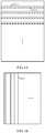
- FIG. 1A and FIG. 1Bare schematic diagrams of electrode arrangements in Embodiment 1 of a touch signal detection circuit according to the present invention.
- the electrode arrangements in the touch signal detection circuit in this embodimentare formed by at least one linear transmitting electrode 11 and at least two linear receiving electrodes 12.
- the transmitting electrode 11 and the receiving electrode 12are in a perpendicular relationship, and the receiving electrode 12 is perpendicular to a source driver line 13 of a display screen.
- FIG. 2is a schematic structural diagram of Embodiment 1 of a touch signal detection circuit according to the present invention. As shown in FIG.
- the touch signal detection circuit in this embodimentmay include a processing unit (not shown), at least one transmitting electrode 11, and at least two receiving electrodes 12.
- the transmitting electrode 11 and the receiving electrode 12may be located on two different layers, and each receiving electrode 12 and each transmitting electrode 11 form one node mutual capacitance 14; and the processing unit may acquire capacitance change values of at least two node mutual capacitances 14 and acquire a location of a touch signal according to the capacitance change values of the at least two node mutual capacitances 14.
- the source driver line 13 of the display screenmay cause interference to all the receiving electrodes 12 when driving is performed.
- the receiving electrode 12receives a signal transmitted by the transmitting electrode 11, the receiving electrode 12 receives a transmitted signal component and also receives an interfering signal component generated at the time of display screen driving. Therefore, it may be deemed that the signal received by the receiving electrode 12 consists of the transmitted signal component and the interfering signal component generated at the time of the display screen driving.
- interfering signals generated at the time of the display screen driving to the receiving electrode 12are close for all receiving electrodes 12 corresponding to a same transmitting electrode 11, and do not change along with a touch status.
- a similar interfering signal component generated at the time of the display screen drivingis found on each receiving electrode; then each receiving electrode subtracts the interfering signal component, and a transmitted signal component transmitted by the transmitting electrode may be obtained. This can reduce interference in the touch signal detection circuit caused by the display screen driving, thereby improving detection precision of the touch signal detection circuit.
- the transmitting electrode and the receiving electrodeare not limited to forms shown in FIG. 2 , and an arrangement of the touch signal detection circuit may also be an electrode arrangement in a single-layer and multi-node manner.
- the forms of the transmitting electrode and the receiving electrodeare not limited to a continuous electrode that is connected entirely, and may be a discontinuous rectangular electrode block or rhombic electrode block.
- a capacitive screen moduleis led out of the screen from these electrode blocks by using conducting wires, and then these conducting wires are connected to each other, which can implement a connection among these electrode blocks so as to form a transmitting electrode or a receiving electrode.
- the foregoing source driver line 13 of the display screenmay be a source driver line in an LCD display.
- the source driver linecharges a display point, and therefore a direction of an interfering signal generated when the display screen displays is consistent with a direction of the source driver line.
- the receiving electrode 12is perpendicular to the source driver line 13 of the display screen, which can ensure that interfering signals generated at the time of the display screen driving and received by at least two receiving electrodes are similar.
- a similar interfering signal component generated at the time of the display screen drivingis found on each receiving electrode, and then each receiving electrode subtracts the interfering signal component. In this way, interference caused by the display screen driving can be reduced.
- the signal received by the receiving electrode 12may be represented by using the capacitance change values, acquired by the processing unit, of the at least two node mutual capacitances 14.
- the interfering signal component generated at the time of the display screen drivingmay be determined according to the capacitance change values of the at least two node mutual capacitances 14, and then the location of the touch signal is acquired according to the capacitance change values of the at least two node mutual capacitances 14 after the interference from the display screen driving is eliminated. This can reduce the interference in touch signal detection caused by the display screen driving, thereby improving precision of touch location detection.
- a transmitting electrode and a receiving electrode in the touch signal detection circuitare perpendicular to each other, the receiving electrode is perpendicular to a source driver line of a display screen, and then a location of a touch signal is acquired according to capacitance change values, acquired by a processing unit, of at least two node mutual capacitances. This can reduce interference in touch signal detection caused by display screen driving, thereby improving precision of touch location detection.
- the processing unitmay specifically be configured to collect statistics on the capacitance change values of the at least two node mutual capacitances, determine an interference value according to a statistical result, and determine the location of the touch signal according to the interference value and the capacitance change values.
- the processing unitcollects statistics on the acquired capacitance change values of the at least two node mutual capacitances, determines the interference value according to the statistical result, may obtain a clean touch signal by subtracting the determined interference value from the acquired capacitance change values of the node mutual capacitances and may precisely determine the location of the touch signal according to the clean touch signal. This can avoid a decrease in detection precision, and even erroneous detection or a detection failure caused by an interfering signal when the touch signal detection circuit performs detection on a touch location. Therefore, precision of touch location detection is improved.
- a processing unitcollects statistics on capacitance change values of at least two node mutual capacitances, determines an interference value according to a statistical result and determines a location of a touch signal according to the interference value and the capacitance change values. This can reduce interference in touch signal detection caused by display screen driving, thereby improving precision of touch location detection.
- the processing unitmay specifically be configured to divide the capacitance change values into two groups according to a numerical range of the capacitance change values, use an average value of or one of all capacitance change values in one group that includes a larger number of capacitance change values as the interference value, obtain a data value by subtracting the interference value from the capacitance change values, and take a location, at which the data value is greater than a preset value, of a node mutual capacitance as the location of the touch signal.
- a touch actiongenerates a touch signal only in a relatively small area
- the touch signal detection circuitmay be divided into a touch area and a non-touch area.
- the capacitance change valuesmay be divided into two groups according to the numerical range of the capacitance change values.
- the group that includes the larger number of capacitance change valuesmay be considered to be in the non-touch area, and the capacitance change values in this group are generated mainly due to impact exerted by the interfering signal on the receiving electrode.
- the average value of or one of all the capacitance change values in the group that includes the larger number of capacitance change valuesis used as the interference value.
- the data valueis obtained by subtracting the interference value from the capacitance change values, where it may be considered that the data value is generated due to impact exerted by the clean touch signal on the receiving electrode. Then, the location, at which the data value is greater than the preset value, of the node mutual capacitance is taken as the location of the touch signal.
- interference valueis not limited to the average value of or one of all the capacitance change values in the group that includes the larger number of capacitance change values.
- Statisticsmay further be collected on the acquired capacitance change values by using related methods so as to determine the interference value.
- a processing unitdivides capacitance change values into two groups according to a numerical range of the capacitance change values, uses an average value of or one of all capacitance change values in one group that includes a larger number of capacitance change values as an interference value, obtains a data value by subtracting the interference value from the capacitance change values and takes a location, at which the data value is greater than a preset value, of a node mutual capacitance as a location of a touch signal.
- Thiscan reduce interference in touch signal detection caused by display screen driving, thereby improving precision of touch location detection.
- An embodiment of the present inventionfurther provides a touch device, and the touch device may include a display screen and the touch signal detection circuit in any one of the foregoing embodiments.
- the touch device in this embodiment of the present inventionincludes but is not limited to a mobile phone that has a touch signal detection circuit, personal digital assistant (Personal Digital Assistant, PDA for short), a wireless handheld device, a wireless netbook, a portable computer, an MP3 player, an MP4 player, and the like that have a touch signal detection circuit.
- PDAPersonal Digital Assistant
- a touch device provided in an embodimentincludes a display screen and the touch signal detection circuit in any one of the foregoing embodiments.
- a transmitting electrodeis perpendicular to a receiving electrode
- the receiving electrodeis perpendicular to a source driver line of the display screen. This can reduce interference in touch signal detection caused by display screen driving, thereby improving precision of touch location detection.
- FIG. 3is a flowchart of Embodiment 1 of a touch signal detection method according to the present invention.
- the touch signal detection method in this embodimentincludes: S301. Acquire capacitance change values of at least two node mutual capacitances, where the at least two node capacitances are formed by at least two linear receiving electrodes and at least one linear transmitting electrode, the transmitting electrode is perpendicular to the receiving electrode, the receiving electrode is perpendicular to a source driver line of a display screen, and each receiving electrode and each transmitting electrode form one node mutual capacitance.
- the foregoing at least two node mutual capacitancesare formed by the at least two linear receiving electrodes and the at least one linear transmitting electrode.
- the transmitting electrodeis perpendicular to the receiving electrode
- the receiving electrodeis perpendicular to the source driver line of the display screen, which may make an interfering signal generated when the source driver line of the display screen performs display driving cause interference to all the receiving electrodes.
- the receiving electrodereceives a signal transmitted by the transmitting electrode
- the receiving electrodereceives a transmitted signal component and also receives an interfering signal component generated at the time of display screen driving. Therefore, it may be deemed that the signal in the receiving electrode consists of the transmitted signal component and the interfering signal component generated at the time of the display screen driving.
- interfering signal component generated at the time of the display screen driving to the receiving electrodeis almost not affected by a finger touch
- interfering signals generated at the time of the display screen drivingare similar for all receiving electrodes corresponding to a same transmitting electrode and do not change along with different touch statuses.
- the signal received by the receiving electrodemay be represented by using the capacitance change values, acquired by a processing unit, of the at least two node mutual capacitances.
- the interfering signal component generated at the time of the display screen drivingmay be determined according to the capacitance change values of the at least two node mutual capacitances, and then the location of the touch signal is acquired according to the capacitance change values of the at least two node mutual capacitances after the interference from the display screen driving is eliminated. This can reduce the interference in touch signal detection caused by the display screen driving, thereby improving precision of touch location detection.
- This embodimentmay be executed by a processing unit disposed in a touch signal detection circuit, or a processor of a touch device that includes a touch signal detection circuit.
- a processing unitacquires capacitance change values of at least two node mutual capacitances, where the at least two node capacitances are formed by at least two linear receiving electrodes and at least one linear transmitting electrode, the transmitting electrode is perpendicular to the receiving electrode, the receiving electrode is perpendicular to a source driver line of a display screen, and each receiving electrode and each transmitting electrode form one node mutual capacitance; and then a location of a touch signal is acquired according to the capacitance change values of the at least two node mutual capacitances.
- Thiscan reduce interference in touch signal detection caused by display screen driving, thereby improving precision of touch location detection.
- FIG. 4is a flowchart of Embodiment 2 of a touch signal detection method according to the present invention, and the touch signal detection method in this embodiment includes:
- S402.Determine an interference value according to the capacitance change values of the at least two node mutual capacitances.
- a method for determining the interference valuemay be to collect statistics on or calculate the capacitance change values, acquired by a processing unit, of the node mutual capacitances, and may also be implemented by using a specific simulation algorithm.
- a data valuemay be obtained by subtracting the interference value from the capacitance change values, where the data value may represent a clean touch signal, and then touch detecting and locating are performed according to the data value.
- This embodimentmay be executed by a processing unit disposed in a touch signal detection circuit, or a processor of a touch device that includes a touch signal detection circuit.
- FIG. 5A to FIG. 5Dare schematic diagrams of capacitance change values in Embodiment 3 of a touch signal detection method according to the present invention. The following describes in detail the touch signal detection method in this embodiment with reference to FIG. 5A to FIG. 5D .
- 10 node capacitances formed by 1 transmitting electrode and 10 receiving electrodesare used as an example.
- FIG. 5Ais a schematic diagram of capacitance change values detected by a processing unit when there is no interference caused by display screen driving and no touch. When there is no interference caused by the display screen driving and no touch, change values, detected by the processing unit, of the 10 node capacitances are relatively small. These relatively small change values are caused by system noise.
- FIG. 5Ais a schematic diagram of capacitance change values detected by a processing unit when there is no interference caused by display screen driving and no touch. When there is no interference caused by the display screen driving and no touch, change values, detected by the processing unit, of the 10 node capacitances are relatively small. These relatively small change
- FIG. 5Bis a schematic diagram of capacitance change values detected by the processing unit when there is interference caused by display screen driving but no touch. When there is interference caused by the display screen driving but no touch, relatively large capacitance change values may be detected. For the same transmitting electrode, signals received by these receiving electrodes are similar in amplitude, and these interfering signals similar in amplitude can be referred to as interference values of the signals.
- FIG. 5Cis a schematic diagram of capacitance change values detected by the processing unit when there are interference caused by display screen driving and a touch. When there is a touch, a touch signal and an interfering signal caused by the display screen driving are superimposed, and a similar interfering signal caused by the display screen driving may be obtained by means of comparison. A dashed part in FIG.
- FIG. 5Cis interference values.
- FIG. 5Dis a schematic diagram of capacitance change values after interference caused by the display screen driving is eliminated. Because the interference caused by the display screen driving is similar, after a similar signal is eliminated, capacitance change values corresponding to a clean touch signal may be obtained. Specifically, the capacitance variation values corresponding to the clean touch signal may be obtained by subtracting the interference value from the capacitance change values acquired by the processing unit, and then touch detecting and locating are performed according to the capacitance change values corresponding to the clean touch signal.
- a processing unitacquires capacitance change values of at least two node mutual capacitances, where the at least two node capacitances are formed by at least two linear receiving electrodes and at least one linear transmitting electrode, the transmitting electrode is perpendicular to the receiving electrode, the receiving electrode is perpendicular to a source driver line of a display screen, and each receiving electrode and each transmitting electrode form one node mutual capacitance; an interference value is determined according to the capacitance change values of the at least two node mutual capacitances; and then a location of a touch signal is determined according to the interference value and the capacitance change values.
- Thiscan reduce interference in touch signal detection caused by display screen driving, thereby improving precision of touch location detection.
- FIG. 6is a flowchart of Embodiment 4 of a touch signal detection method according to the present invention, and the touch signal detection method in this embodiment includes:
- This embodimentmay be executed by a processing unit disposed in a touch signal detection circuit, or a processor of a touch device that includes a touch signal detection circuit.
- FIG. 7A and FIG. 7Bare schematic diagrams of capacitance change values in Embodiment 5 of a touch signal detection method according to the present invention. The following describes in detail the touch signal detection method in this embodiment with reference to FIG. 7A and FIG. 7B .
- 120 node capacitances formed by 12 transmitting electrodes and 10 receiving electrodesare used as an example.
- FIG. 7Ais another schematic diagram of capacitance change values detected by a processing unit when there is interference caused by display screen driving and a touch.
- a black circle in FIG. 7Aindicates a touch location.
- a processing unit in a touch signal detection circuitperforms touch detecting and locating, it is set that when a capacitance change value is greater than 100, a touch action is deemed to occur.
- existence of interference caused by the display screen drivingleads to fluctuation in many capacitance change values, so that capacitance change values detected in some areas in which no touch action occurs exceed 100, such as capacitance change values in shadow areas in FIG. 7A . As a result, erroneous detection is inevitable.
- an interference value of the 10 capacitance change values that are generated by the same transmitting electrode and received by the 10 receiving electrodesmay be determined.
- a specific determining methodis to divide the capacitance change values into two groups according to the numerical range of the capacitance change values, and use an average value of or one of all capacitance change values in one group that includes a larger number of capacitance change values as the interference value. For example, because the 10 capacitance change values on the second row in FIG. 7A are relatively close, the interference value 120 is one of the 10 capacitance change values. On the eighth row in FIG. 7A , "198, 268, 201" may be included in a first group, the other seven close capacitance change values are included in a second group, and the interference value 120 is a capacitance change value in the second group.
- FIG. 7Bis another schematic diagram of capacitance change values after interference caused by display screen driving is eliminated. A data value is obtained after an interference value is subtracted from each capacitance change value in FIG. 7B .
- a location, at which a capacitance change value is greater than a preset value 100, of a node mutual capacitanceis taken as a location of a touch signal.
- a processing unitacquires capacitance change values of at least two node mutual capacitances, where the at least two node capacitances are formed by at least two linear receiving electrodes and at least one linear transmitting electrode, the transmitting electrode is perpendicular to the receiving electrode, the receiving electrode is perpendicular to a source driver line of a display screen, and each receiving electrode and each transmitting electrode form one node mutual capacitance; an interference value is determined according to the capacitance change values of the at least two node mutual capacitances; the capacitance change values are divided into two groups according to a numerical range of the capacitance change values; an average value of or one of all capacitance change values in one group that includes a larger number of capacitance change values is used as the interference value; a data value is obtained by subtracting the interference value from the capacitance change values; and a location, at which the data value is greater than a preset value, of a node mutual capacitance is taken as
- the programmay be stored in a computer-readable storage medium.
- the foregoing storage mediumincludes: any medium that can store program code, such as a ROM, a RAM, a magnetic disk, or an optical disc.
Landscapes
- Engineering & Computer Science (AREA)
- General Engineering & Computer Science (AREA)
- Theoretical Computer Science (AREA)
- Human Computer Interaction (AREA)
- Physics & Mathematics (AREA)
- General Physics & Mathematics (AREA)
- Position Input By Displaying (AREA)
Description
- Embodiments of the present invention relate to communications technologies, and in particular, to a touch signal detection circuit and method, and a touch device.
- In recent years, a touch control device has become one of the most important input devices, and the touch device may convert a user's touch signal into an electrical signal by using a touch detection circuit. A mutual capacitance induction technology is a typical touch detection method. A touch device that uses the mutual capacitance induction technology includes several transmitting electrodes and several receiving electrodes, and the transmitting electrodes and the receiving electrodes are located on different layers. A node formed between each transmitting electrode and each receiving electrode may be equivalent to one node mutual capacitance. When a user touches the touch device, a change in a node capacitance occurs at a touch point. Therefore, a location of the touch point on the touch device can be determined by detecting change values of all node capacitances in the touch device.
- Currently, the touch device is extensively used in a user equipment that has a display function, such as a mobile phone and a tablet computer. When a liquid crystal display (Liquid Crystal Display, LCD for short) performs displaying a generated electromagnetic signal may cause interference to touch detection of the touch device, which leads to a decrease in detection precision, and even erroneous detection or a detection failure when the touch device performs detection on a touch location.
US 2012 139 868 A1 discloses a capacitive touch panel including a scanning circuit portion, a capacitance detection circuit portion for detecting a capacitance detection signal of the each detecting electrode in the 1st to n-th groups, and a control circuit portion for calculating a capacitance detection signal change amount, and calculating coordinates of a touch position based on the capacitance detection signal change amounts. - The present invention provides a touch signal detection circuit and method, and a touch device, so as to enhance a capability of the touch device to resist interference from a display device, and improve precision of touch location detection.
- A first aspect of the present invention provides a touch signal detection circuit according to
claim 1. - A second aspect of the present invention provides a touch device, and the touch device includes a display screen and the touch signal detection circuit according to the first aspect.
- A third aspect of the present invention provides a touch signal detection method according to
claim 3. - The present invention provides a touch signal detection circuit and method, and a touch device. By means of design, a transmitting electrode and a receiving electrode of the touch signal detection circuit are perpendicular to each other, the receiving electrode is perpendicular to a source driver line of a display greater than a preset value, of a node mutual capacitance as the location of the touch signal.
- The present invention provides a touch signal detection circuit and method, and a touch device. By means of design, a transmitting electrode and a receiving electrode of the touch signal detection circuit are perpendicular to each other, the receiving electrode is perpendicular to a source driver line of a display screen, and then a location of a touch signal is acquired according to capacitance change values, acquired by a processing unit, of at least two node mutual capacitances. This can reduce interference in touch signal detection caused by display screen driving, thereby improving precision of touch location detection.
- To describe the technical solutions in the embodiments of the present invention more clearly, the following briefly introduces the accompanying drawings required for describing the embodiments or the prior art. Apparently, the accompanying drawings in the following description show some embodiments of the present invention, and persons of ordinary skill in the art may still derive other drawings from these accompanying drawings without creative efforts.
FIG. 1A and FIG. 1B are schematic diagrams of electrode arrangements inEmbodiment 1 of a touch signal detection circuit according to the present invention;FIG. 2 is a schematic structural diagram ofEmbodiment 1 of a touch signal detection circuit according to the present invention;FIG. 3 is a flowchart ofEmbodiment 1 of a touch signal detection method according to the present invention;FIG. 4 is a flowchart ofEmbodiment 2 of a touch signal detection method according to the present invention;FIG. 5A to FIG. 5D are schematic diagrams of capacitance change values inEmbodiment 3 of a touch signal detection method according to the present invention;FIG. 6 is a flowchart ofEmbodiment 4 of a touch signal detection method according to the present invention; andFIG. 7A andFIG. 7B are schematic diagrams of capacitance change values inEmbodiment 5 of a touch signal detection method according to the present invention.- To make the objectives, technical solutions, and advantages of the embodiments of the present invention clearer, the following clearly and completely describes the technical solutions in the embodiments of the present invention with reference to the accompanying drawings in the embodiments of the present invention.
FIG. 1A and FIG. 1B are schematic diagrams of electrode arrangements inEmbodiment 1 of a touch signal detection circuit according to the present invention. As shown inFIG. 1A and FIG. 1B , the electrode arrangements in the touch signal detection circuit in this embodiment are formed by at least one linear transmittingelectrode 11 and at least twolinear receiving electrodes 12. The transmittingelectrode 11 and the receivingelectrode 12 are in a perpendicular relationship, and the receivingelectrode 12 is perpendicular to asource driver line 13 of a display screen.FIG. 2 is a schematic structural diagram ofEmbodiment 1 of a touch signal detection circuit according to the present invention. As shown inFIG. 2 , the touch signal detection circuit in this embodiment may include a processing unit (not shown), at least one transmittingelectrode 11, and at least two receivingelectrodes 12. The transmittingelectrode 11 and the receivingelectrode 12 may be located on two different layers, and each receivingelectrode 12 and each transmittingelectrode 11 form one nodemutual capacitance 14; and the processing unit may acquire capacitance change values of at least two nodemutual capacitances 14 and acquire a location of a touch signal according to the capacitance change values of the at least two nodemutual capacitances 14.- Specifically, in the touch signal detection circuit in this embodiment, because the transmitting
electrode 11 and the receivingelectrode 12 are in the perpendicular relationship and the receivingelectrode 12 is perpendicular to thesource driver line 13 of the display screen, thesource driver line 13 of the display screen may cause interference to all the receivingelectrodes 12 when driving is performed. When the receivingelectrode 12 receives a signal transmitted by the transmittingelectrode 11, the receivingelectrode 12 receives a transmitted signal component and also receives an interfering signal component generated at the time of display screen driving. Therefore, it may be deemed that the signal received by the receivingelectrode 12 consists of the transmitted signal component and the interfering signal component generated at the time of the display screen driving. However, because an interfering signal generated at the time of the display screen driving to the receivingelectrode 12 is almost not affected by a finger touch, interfering signals generated at the time of the display screen driving are close for all receivingelectrodes 12 corresponding to a same transmittingelectrode 11, and do not change along with a touch status. For one transmittingelectrode 11, a similar interfering signal component generated at the time of the display screen driving is found on each receiving electrode; then each receiving electrode subtracts the interfering signal component, and a transmitted signal component transmitted by the transmitting electrode may be obtained. This can reduce interference in the touch signal detection circuit caused by the display screen driving, thereby improving detection precision of the touch signal detection circuit. - It may be understood that the transmitting electrode and the receiving electrode are not limited to forms shown in
FIG. 2 , and an arrangement of the touch signal detection circuit may also be an electrode arrangement in a single-layer and multi-node manner. The forms of the transmitting electrode and the receiving electrode are not limited to a continuous electrode that is connected entirely, and may be a discontinuous rectangular electrode block or rhombic electrode block. A capacitive screen module is led out of the screen from these electrode blocks by using conducting wires, and then these conducting wires are connected to each other, which can implement a connection among these electrode blocks so as to form a transmitting electrode or a receiving electrode. - The foregoing
source driver line 13 of the display screen may be a source driver line in an LCD display. When the display screen displays, the source driver line charges a display point, and therefore a direction of an interfering signal generated when the display screen displays is consistent with a direction of the source driver line. In this embodiment, thereceiving electrode 12 is perpendicular to thesource driver line 13 of the display screen, which can ensure that interfering signals generated at the time of the display screen driving and received by at least two receiving electrodes are similar. A similar interfering signal component generated at the time of the display screen driving is found on each receiving electrode, and then each receiving electrode subtracts the interfering signal component. In this way, interference caused by the display screen driving can be reduced. - The signal received by the
receiving electrode 12 may be represented by using the capacitance change values, acquired by the processing unit, of the at least two nodemutual capacitances 14. The interfering signal component generated at the time of the display screen driving may be determined according to the capacitance change values of the at least two nodemutual capacitances 14, and then the location of the touch signal is acquired according to the capacitance change values of the at least two nodemutual capacitances 14 after the interference from the display screen driving is eliminated. This can reduce the interference in touch signal detection caused by the display screen driving, thereby improving precision of touch location detection. - It should be noted that technical solutions in this embodiment of the present invention are not limited to reduction of the interference caused by the display screen driving, but are also applicable to reduction of interference that affects overall data characteristics of the touch signal detection circuit, such as interference of a temperature change and a humidity change that causes overall offset to the touch signal detection circuit in signal detection, or interference of a radio frequency (Radio Frequency, RF for short) and the like that affect all receiving electrodes corresponding to a same transmitting electrode simultaneously.
- According to a touch signal detection circuit provided in this embodiment, by means of design, a transmitting electrode and a receiving electrode in the touch signal detection circuit are perpendicular to each other, the receiving electrode is perpendicular to a source driver line of a display screen, and then a location of a touch signal is acquired according to capacitance change values, acquired by a processing unit, of at least two node mutual capacitances. This can reduce interference in touch signal detection caused by display screen driving, thereby improving precision of touch location detection.
- Further, based on
Embodiment 1 of the touch signal detection circuit provided in the present invention, the processing unit may specifically be configured to collect statistics on the capacitance change values of the at least two node mutual capacitances, determine an interference value according to a statistical result, and determine the location of the touch signal according to the interference value and the capacitance change values. - Specifically, the processing unit collects statistics on the acquired capacitance change values of the at least two node mutual capacitances, determines the interference value according to the statistical result, may obtain a clean touch signal by subtracting the determined interference value from the acquired capacitance change values of the node mutual capacitances and may precisely determine the location of the touch signal according to the clean touch signal. This can avoid a decrease in detection precision, and even erroneous detection or a detection failure caused by an interfering signal when the touch signal detection circuit performs detection on a touch location. Therefore, precision of touch location detection is improved.
- According to a touch signal detection circuit provided in this embodiment, a processing unit collects statistics on capacitance change values of at least two node mutual capacitances, determines an interference value according to a statistical result and determines a location of a touch signal according to the interference value and the capacitance change values. This can reduce interference in touch signal detection caused by display screen driving, thereby improving precision of touch location detection.
- Furthermore, based on
Embodiment 1 of the touch signal detection circuit provided in the present invention, the processing unit may specifically be configured to divide the capacitance change values into two groups according to a numerical range of the capacitance change values, use an average value of or one of all capacitance change values in one group that includes a larger number of capacitance change values as the interference value, obtain a data value by subtracting the interference value from the capacitance change values, and take a location, at which the data value is greater than a preset value, of a node mutual capacitance as the location of the touch signal. - Specifically, compared with the entire touch signal detection circuit, a touch action generates a touch signal only in a relatively small area, and the touch signal detection circuit may be divided into a touch area and a non-touch area. There is a relatively large difference between capacitance change values in the touch area and capacitance change values in the non-touch area. Therefore, the capacitance change values may be divided into two groups according to the numerical range of the capacitance change values. The group that includes the larger number of capacitance change values may be considered to be in the non-touch area, and the capacitance change values in this group are generated mainly due to impact exerted by the interfering signal on the receiving electrode. The average value of or one of all the capacitance change values in the group that includes the larger number of capacitance change values is used as the interference value. The data value is obtained by subtracting the interference value from the capacitance change values, where it may be considered that the data value is generated due to impact exerted by the clean touch signal on the receiving electrode. Then, the location, at which the data value is greater than the preset value, of the node mutual capacitance is taken as the location of the touch signal.
- It may be understood that the foregoing interference value is not limited to the average value of or one of all the capacitance change values in the group that includes the larger number of capacitance change values. Statistics may further be collected on the acquired capacitance change values by using related methods so as to determine the interference value.
- According to a touch signal detection circuit provided in this embodiment, a processing unit divides capacitance change values into two groups according to a numerical range of the capacitance change values, uses an average value of or one of all capacitance change values in one group that includes a larger number of capacitance change values as an interference value, obtains a data value by subtracting the interference value from the capacitance change values and takes a location, at which the data value is greater than a preset value, of a node mutual capacitance as a location of a touch signal. This can reduce interference in touch signal detection caused by display screen driving, thereby improving precision of touch location detection.
- An embodiment of the present invention further provides a touch device, and the touch device may include a display screen and the touch signal detection circuit in any one of the foregoing embodiments.
- The touch device in this embodiment of the present invention includes but is not limited to a mobile phone that has a touch signal detection circuit, personal digital assistant (Personal Digital Assistant, PDA for short), a wireless handheld device, a wireless netbook, a portable computer, an MP3 player, an MP4 player, and the like that have a touch signal detection circuit.
- A touch device provided in an embodiment includes a display screen and the touch signal detection circuit in any one of the foregoing embodiments. In the touch signal detection circuit in the touch device, a transmitting electrode is perpendicular to a receiving electrode, and the receiving electrode is perpendicular to a source driver line of the display screen. This can reduce interference in touch signal detection caused by display screen driving, thereby improving precision of touch location detection.
FIG. 3 is a flowchart ofEmbodiment 1 of a touch signal detection method according to the present invention. As shown inFIG. 3 , the touch signal detection method in this embodiment includes:
S301. Acquire capacitance change values of at least two node mutual capacitances, where the at least two node capacitances are formed by at least two linear receiving electrodes and at least one linear transmitting electrode, the transmitting electrode is perpendicular to the receiving electrode, the receiving electrode is perpendicular to a source driver line of a display screen, and each receiving electrode and each transmitting electrode form one node mutual capacitance.- Specifically, the foregoing at least two node mutual capacitances are formed by the at least two linear receiving electrodes and the at least one linear transmitting electrode. The transmitting electrode is perpendicular to the receiving electrode, and the receiving electrode is perpendicular to the source driver line of the display screen, which may make an interfering signal generated when the source driver line of the display screen performs display driving cause interference to all the receiving electrodes. When the receiving electrode receives a signal transmitted by the transmitting electrode, the receiving electrode receives a transmitted signal component and also receives an interfering signal component generated at the time of display screen driving. Therefore, it may be deemed that the signal in the receiving electrode consists of the transmitted signal component and the interfering signal component generated at the time of the display screen driving. However, because the interfering signal component generated at the time of the display screen driving to the receiving electrode is almost not affected by a finger touch, interfering signals generated at the time of the display screen driving are similar for all receiving electrodes corresponding to a same transmitting electrode and do not change along with different touch statuses.
- S302. Acquire a location of a touch signal according to the capacitance change values of the at least two node mutual capacitances.
- Specifically, the signal received by the receiving electrode may be represented by using the capacitance change values, acquired by a processing unit, of the at least two node mutual capacitances. The interfering signal component generated at the time of the display screen driving may be determined according to the capacitance change values of the at least two node mutual capacitances, and then the location of the touch signal is acquired according to the capacitance change values of the at least two node mutual capacitances after the interference from the display screen driving is eliminated. This can reduce the interference in touch signal detection caused by the display screen driving, thereby improving precision of touch location detection.
- This embodiment may be executed by a processing unit disposed in a touch signal detection circuit, or a processor of a touch device that includes a touch signal detection circuit.
- It should be noted that technical solutions in this embodiment of the present invention are not limited to elimination of the interference caused by the display screen driving, but are also applicable to elimination of interference that affects overall data characteristics of the touch signal detection circuit, such as interference of a temperature change and a humidity change that causes overall offset to the touch signal detection circuit in signal detection, or interference of a radio frequency, RF for short, and the like that affect all receiving electrodes corresponding to a same transmitting electrode simultaneously.
- According to a touch signal detection method provided in this embodiment, a processing unit acquires capacitance change values of at least two node mutual capacitances, where the at least two node capacitances are formed by at least two linear receiving electrodes and at least one linear transmitting electrode, the transmitting electrode is perpendicular to the receiving electrode, the receiving electrode is perpendicular to a source driver line of a display screen, and each receiving electrode and each transmitting electrode form one node mutual capacitance; and then a location of a touch signal is acquired according to the capacitance change values of the at least two node mutual capacitances. This can reduce interference in touch signal detection caused by display screen driving, thereby improving precision of touch location detection.
FIG. 4 is a flowchart ofEmbodiment 2 of a touch signal detection method according to the present invention, and the touch signal detection method in this embodiment includes:- S401. Acquire capacitance change values of at least two node mutual capacitances, where the at least two node capacitances are formed by at least two linear receiving electrodes and at least one linear transmitting electrode, the transmitting electrode is perpendicular to the receiving electrode, the receiving electrode is perpendicular to a source driver line of a display screen, and each receiving electrode and each transmitting electrode form one node mutual capacitance.
- S402. Determine an interference value according to the capacitance change values of the at least two node mutual capacitances.
- A method for determining the interference value may be to collect statistics on or calculate the capacitance change values, acquired by a processing unit, of the node mutual capacitances, and may also be implemented by using a specific simulation algorithm.
- S403. Determine a location of a touch signal according to the interference value and the capacitance change values.
- For example, a data value may be obtained by subtracting the interference value from the capacitance change values, where the data value may represent a clean touch signal, and then touch detecting and locating are performed according to the data value.
- This embodiment may be executed by a processing unit disposed in a touch signal detection circuit, or a processor of a touch device that includes a touch signal detection circuit.
FIG. 5A to FIG. 5D are schematic diagrams of capacitance change values inEmbodiment 3 of a touch signal detection method according to the present invention. The following describes in detail the touch signal detection method in this embodiment with reference toFIG. 5A to FIG. 5D . As shown inFIG. 5A to FIG. 5D , 10 node capacitances formed by 1 transmitting electrode and 10 receiving electrodes are used as an example.FIG. 5A is a schematic diagram of capacitance change values detected by a processing unit when there is no interference caused by display screen driving and no touch. When there is no interference caused by the display screen driving and no touch, change values, detected by the processing unit, of the 10 node capacitances are relatively small. These relatively small change values are caused by system noise.FIG. 5B is a schematic diagram of capacitance change values detected by the processing unit when there is interference caused by display screen driving but no touch. When there is interference caused by the display screen driving but no touch, relatively large capacitance change values may be detected. For the same transmitting electrode, signals received by these receiving electrodes are similar in amplitude, and these interfering signals similar in amplitude can be referred to as interference values of the signals.FIG. 5C is a schematic diagram of capacitance change values detected by the processing unit when there are interference caused by display screen driving and a touch. When there is a touch, a touch signal and an interfering signal caused by the display screen driving are superimposed, and a similar interfering signal caused by the display screen driving may be obtained by means of comparison. A dashed part inFIG. 5C is interference values.FIG. 5D is a schematic diagram of capacitance change values after interference caused by the display screen driving is eliminated. Because the interference caused by the display screen driving is similar, after a similar signal is eliminated, capacitance change values corresponding to a clean touch signal may be obtained. Specifically, the capacitance variation values corresponding to the clean touch signal may be obtained by subtracting the interference value from the capacitance change values acquired by the processing unit, and then touch detecting and locating are performed according to the capacitance change values corresponding to the clean touch signal.- According to a touch signal detection method provided in this embodiment, a processing unit acquires capacitance change values of at least two node mutual capacitances, where the at least two node capacitances are formed by at least two linear receiving electrodes and at least one linear transmitting electrode, the transmitting electrode is perpendicular to the receiving electrode, the receiving electrode is perpendicular to a source driver line of a display screen, and each receiving electrode and each transmitting electrode form one node mutual capacitance; an interference value is determined according to the capacitance change values of the at least two node mutual capacitances; and then a location of a touch signal is determined according to the interference value and the capacitance change values. This can reduce interference in touch signal detection caused by display screen driving, thereby improving precision of touch location detection.
FIG. 6 is a flowchart ofEmbodiment 4 of a touch signal detection method according to the present invention, and the touch signal detection method in this embodiment includes:- S601. Acquire capacitance change values of at least two node mutual capacitances, where the at least two node capacitances are formed by at least two linear receiving electrodes and at least one linear transmitting electrode, the transmitting electrode is perpendicular to the receiving electrode, the receiving electrode is perpendicular to a source driver line of a display screen, and each receiving electrode and each transmitting electrode form one node mutual capacitance.
- S602. Divide the capacitance change values into two groups according to a numerical range of the capacitance change values, and use an average value of or one of all capacitance change values in one group that includes a larger number of capacitance change values as an interference value.
- S603. Obtain a data value by subtracting the interference value from the capacitance change values.
- S604. Take a location, at which the data value is greater than a preset value, of a node mutual capacitance as a location of a touch signal.
- This embodiment may be executed by a processing unit disposed in a touch signal detection circuit, or a processor of a touch device that includes a touch signal detection circuit.
FIG. 7A andFIG. 7B are schematic diagrams of capacitance change values inEmbodiment 5 of a touch signal detection method according to the present invention. The following describes in detail the touch signal detection method in this embodiment with reference toFIG. 7A andFIG. 7B . As shown inFIG. 7A andFIG. 7B , 120 node capacitances formed by 12 transmitting electrodes and 10 receiving electrodes are used as an example.FIG. 7A is another schematic diagram of capacitance change values detected by a processing unit when there is interference caused by display screen driving and a touch. A black circle inFIG. 7A indicates a touch location. For example, when a processing unit in a touch signal detection circuit performs touch detecting and locating, it is set that when a capacitance change value is greater than 100, a touch action is deemed to occur. However, existence of interference caused by the display screen driving leads to fluctuation in many capacitance change values, so that capacitance change values detected in some areas in which no touch action occurs exceed 100, such as capacitance change values in shadow areas inFIG. 7A . As a result, erroneous detection is inevitable.- According to a numerical range of 10 capacitance change values that are generated by a same transmitting electrode and received by the 10 receiving electrodes in
FIG. 7A , an interference value of the 10 capacitance change values that are generated by the same transmitting electrode and received by the 10 receiving electrodes may be determined. A specific determining method is to divide the capacitance change values into two groups according to the numerical range of the capacitance change values, and use an average value of or one of all capacitance change values in one group that includes a larger number of capacitance change values as the interference value. For example, because the 10 capacitance change values on the second row inFIG. 7A are relatively close, theinterference value 120 is one of the 10 capacitance change values. On the eighth row inFIG. 7A , "198, 268, 201" may be included in a first group, the other seven close capacitance change values are included in a second group, and theinterference value 120 is a capacitance change value in the second group. FIG. 7B is another schematic diagram of capacitance change values after interference caused by display screen driving is eliminated. A data value is obtained after an interference value is subtracted from each capacitance change value inFIG. 7B . InFIG. 7B , a location, at which a capacitance change value is greater than a preset value 100, of a node mutual capacitance is taken as a location of a touch signal.- According to a touch signal detection method provided in this embodiment, a processing unit acquires capacitance change values of at least two node mutual capacitances, where the at least two node capacitances are formed by at least two linear receiving electrodes and at least one linear transmitting electrode, the transmitting electrode is perpendicular to the receiving electrode, the receiving electrode is perpendicular to a source driver line of a display screen, and each receiving electrode and each transmitting electrode form one node mutual capacitance; an interference value is determined according to the capacitance change values of the at least two node mutual capacitances; the capacitance change values are divided into two groups according to a numerical range of the capacitance change values; an average value of or one of all capacitance change values in one group that includes a larger number of capacitance change values is used as the interference value; a data value is obtained by subtracting the interference value from the capacitance change values; and a location, at which the data value is greater than a preset value, of a node mutual capacitance is taken as a location of a touch signal. This can reduce interference in touch signal detection caused by display screen driving, thereby improving precision of touch location detection.
- Persons of ordinary skill in the art may understand that all or a part of the steps of the method embodiments may be implemented by a program instructing relevant hardware. The program may be stored in a computer-readable storage medium. When the program runs, the steps of the method embodiments are performed. The foregoing storage medium includes: any medium that can store program code, such as a ROM, a RAM, a magnetic disk, or an optical disc.
- Finally, it should be noted that the foregoing embodiments are merely intended for describing the technical solutions of the present invention, but not for limiting the present invention. Although the present invention is described in detail with reference to the foregoing embodiments, persons of ordinary skill in the art should understand that they may still make modifications to the technical solutions described in the foregoing embodiments or make equivalent replacements to some or all technical features thereof, without departing from the scope of the technical solutions of the embodiments of the present invention.
Claims (3)
- A touch signal detection circuit, comprising a processing unit, at least one linear transmitting electrode (11), and at least two linear receiving electrodes (12), wherein:the transmitting electrode (11) is perpendicular to the at least two receiving electrodes (12), the at least two receiving electrodes (12) are perpendicular to a source driver line (13) of a display screen, and each of the at least two receiving electrodes (12) and each transmitting electrode (11) form one node mutual capacitance; andthe processing unit is configured to acquire capacitance change values of at least two node mutual capacitances, and acquire a location of a touch signal according to the capacitance change values of the at least two node mutual capacitances;wherein the processing unit is specifically configured to collect statistics on the capacitance change values of the at least two node mutual capacitances, determine an interference value according to a statistical result when the touch signal detection circuit performs detection on a touch location, and determine the location of the touch signal according to the interference value and the capacitance change values; andcharacterised in that the processing unit is specifically configured to divide the capacitance change values into two groups according to a numerical range of the capacitance change values, use an average value of all capacitance change values in one group that comprises a larger number of capacitance change values as the interference value, obtain a data value by subtracting the interference value from each of the capacitance change values, and take a location, at which the data value is greater than a preset value, of a node mutual capacitance as the location of the touch signal.
- A touch device, comprising a display screen and the touch signal detection circuit according claim 1.
- A touch signal detection method, comprising:acquiring capacitance change values of at least two node mutual capacitances, wherein the at least two node capacitances are formed by at least two linear receiving electrodes (12) and at least one linear transmitting electrode (11), the transmitting electrode (11) is perpendicular to the at least two receiving electrodes (12), the at least two receiving electrodes (12) are perpendicular to a source driver line (13) of a display screen, and each of at least two receiving electrodes (12) and each transmitting electrode (11) form one node mutual capacitance; andacquiring a location of a touch signal according to the capacitance change values of the at least two node mutual capacitances;wherein the acquiring a location of a touch signal according to the capacitance change values of the at least two node mutual capacitances comprises:determining an interference value according to the capacitance change values of the at least two node mutual capacitances when the touch signal detection circuit performs detection on a touch location; anddetermining the location of the touch signal according to the interference value and the capacitance change values;characterised in that the determining an interference value according to the capacitance change values of the at least two node mutual capacitances comprises:dividing the capacitance change values into two groups according to a numerical range of the capacitance change values, and using an average value of all capacitance change values in one group that comprises a larger number of capacitance change values as the interference value; andthe determining the location of the touch signal according to the interference value and the capacitance change values comprises: obtaining a data value by subtracting the interference value from each of the capacitance change values; andusing a location, at which the data value is greater than a preset value, of a node mutual capacitance as the location of the touch signal.
Applications Claiming Priority (2)
| Application Number | Priority Date | Filing Date | Title |
|---|---|---|---|
| CN201310022720.3ACN103941927A (en) | 2013-01-22 | 2013-01-22 | Touch signal detecting circuit and method and touch equipment |
| PCT/CN2014/071118WO2014114234A1 (en) | 2013-01-22 | 2014-01-22 | Touch signal detection circuit and method, and touch device |
Publications (3)
| Publication Number | Publication Date |
|---|---|
| EP2853996A1 EP2853996A1 (en) | 2015-04-01 |
| EP2853996A4 EP2853996A4 (en) | 2015-08-26 |
| EP2853996B1true EP2853996B1 (en) | 2018-11-14 |
Family
ID=51189616
Family Applications (1)
| Application Number | Title | Priority Date | Filing Date |
|---|---|---|---|
| EP14743739.6AActiveEP2853996B1 (en) | 2013-01-22 | 2014-01-22 | Touch signal detection circuit and method |
Country Status (5)
| Country | Link |
|---|---|
| US (1) | US9720540B2 (en) |
| EP (1) | EP2853996B1 (en) |
| JP (1) | JP6010826B2 (en) |
| CN (1) | CN103941927A (en) |
| WO (1) | WO2014114234A1 (en) |
Families Citing this family (8)
| Publication number | Priority date | Publication date | Assignee | Title |
|---|---|---|---|---|
| US10289256B2 (en)* | 2014-01-22 | 2019-05-14 | Tactual Labs Co. | Dynamic assignment of possible channels in a touch sensor |
| JP6527343B2 (en)* | 2014-08-01 | 2019-06-05 | 株式会社 ハイディープHiDeep Inc. | Touch input device |
| TWI525501B (en)* | 2014-10-23 | 2016-03-11 | 瑞鼎科技股份有限公司 | Touch filter circuit |
| CN106708336B (en)* | 2015-07-14 | 2020-08-25 | 比亚迪股份有限公司 | Capacitive touch screen |
| US10061437B2 (en)* | 2015-09-30 | 2018-08-28 | Synaptics Incorporated | Active canceling of display noise in simultaneous display and touch sensing using an impulse response |
| JP7092480B2 (en)* | 2017-09-27 | 2022-06-28 | エルジー ディスプレイ カンパニー リミテッド | Sensor device and its control method |
| CN111527472B (en)* | 2018-10-31 | 2023-11-07 | 深圳市汇顶科技股份有限公司 | Noise reduction method, touch display device and computer-readable storage medium |
| CN113918039B (en)* | 2020-07-09 | 2024-11-26 | 青岛海信商用显示股份有限公司 | Signal processing method, device, equipment and storage medium |
Citations (2)
| Publication number | Priority date | Publication date | Assignee | Title |
|---|---|---|---|---|
| EP0665508A2 (en)* | 1993-12-03 | 1995-08-02 | Synaptics, Incorporated | Touch pad driven handheld computing device |
| JP2010003285A (en)* | 2008-05-21 | 2010-01-07 | Mitsubishi Electric Corp | Touch panel, and display device provided with the same |
Family Cites Families (12)
| Publication number | Priority date | Publication date | Assignee | Title |
|---|---|---|---|---|
| JP3972834B2 (en)* | 2003-02-21 | 2007-09-05 | ソニー株式会社 | Input device, portable electronic device, and input method of portable electronic device |
| TWI417766B (en)* | 2008-05-23 | 2013-12-01 | Innolux Corp | Touch-sensitive liquid crystal display device and method for driving same |
| US8963843B2 (en)* | 2008-08-28 | 2015-02-24 | Stmicroelectronics Asia Pacific Pte. Ltd. | Capacitive touch sensor system |
| CN101661359B (en)* | 2009-10-10 | 2011-06-01 | 友达光电股份有限公司 | Capacitive touch detection system and its detection signal receiving and waveform shaping module |
| US8395597B2 (en)* | 2009-10-27 | 2013-03-12 | Motorola Mobility Llc | Method and device for providing an equi-potential touch screen |
| CN101727242B (en)* | 2009-12-21 | 2012-05-30 | 苏州瀚瑞微电子有限公司 | Method for sensing multiclutch on touch panel |
| CN101840297B (en) | 2010-04-07 | 2012-09-05 | 敦泰科技(深圳)有限公司 | Touch detection method and detection circuit of capacitance-type touch screen |
| JP5455126B2 (en)* | 2010-04-28 | 2014-03-26 | 株式会社ジャパンディスプレイ | Display device with touch detection function, driving method, and electronic device |
| JP5307110B2 (en)* | 2010-12-01 | 2013-10-02 | 株式会社ジャパンディスプレイ | Touch panel |
| CN102707821B (en)* | 2011-03-28 | 2015-04-22 | 深圳市汇顶科技股份有限公司 | Method and system for de-noising touch detection device |
| US9196207B2 (en)* | 2011-05-03 | 2015-11-24 | Apple Inc. | System and method for controlling the slew rate of a signal |
| US9870103B2 (en)* | 2012-01-03 | 2018-01-16 | Silicon Laboratories Inc. | Controller and method for controlling a capacitive touch screen or the like |
- 2013
- 2013-01-22CNCN201310022720.3Apatent/CN103941927A/enactivePending
- 2014
- 2014-01-22JPJP2015523412Apatent/JP6010826B2/enactiveActive
- 2014-01-22EPEP14743739.6Apatent/EP2853996B1/enactiveActive
- 2014-01-22WOPCT/CN2014/071118patent/WO2014114234A1/enactiveApplication Filing
- 2014-12-18USUS14/575,064patent/US9720540B2/enactiveActive
Patent Citations (2)
| Publication number | Priority date | Publication date | Assignee | Title |
|---|---|---|---|---|
| EP0665508A2 (en)* | 1993-12-03 | 1995-08-02 | Synaptics, Incorporated | Touch pad driven handheld computing device |
| JP2010003285A (en)* | 2008-05-21 | 2010-01-07 | Mitsubishi Electric Corp | Touch panel, and display device provided with the same |
Also Published As
| Publication number | Publication date |
|---|---|
| CN103941927A (en) | 2014-07-23 |
| JP2015522893A (en) | 2015-08-06 |
| WO2014114234A1 (en) | 2014-07-31 |
| JP6010826B2 (en) | 2016-10-19 |
| US20150103046A1 (en) | 2015-04-16 |
| EP2853996A1 (en) | 2015-04-01 |
| EP2853996A4 (en) | 2015-08-26 |
| US9720540B2 (en) | 2017-08-01 |
Similar Documents
| Publication | Publication Date | Title |
|---|---|---|
| EP2853996B1 (en) | Touch signal detection circuit and method | |
| CN109997348B (en) | A terminal interface display method and terminal | |
| US20140368460A1 (en) | Touch detection method and apparatus, and touch screen system | |
| US9547399B2 (en) | Injected touch noise analysis | |
| US9244578B2 (en) | Detecting gestures on the side of a computing device | |
| EP2811379A1 (en) | Touch liquid crystal display device | |
| US8692802B1 (en) | Method and apparatus for calculating coordinates with high noise immunity in touch applications | |
| EP2958000A2 (en) | Touch panel and touch detection circuit | |
| US10126870B2 (en) | Techniques for mitigating noise in capacitive sensing devices | |
| US9946391B2 (en) | Sensing objects using multiple transmitter frequencies | |
| US20150070297A1 (en) | Control method for touch panel | |
| EP2804083A1 (en) | Screen unlocking system and method | |
| KR20140071282A (en) | Electronic device and method for controlling zooming of displayed object | |
| WO2015062372A1 (en) | Method and apparatus for selecting objects | |
| KR20120082819A (en) | Positional information correction device, touch sensor, positional information correction method, and program | |
| JP2016006609A (en) | Electronic apparatus | |
| JP3164187U (en) | Signal-sensitive architecture for pressure-sensitive tablets | |
| CN107003758B (en) | Ghost point processing method and user equipment | |
| US9329740B2 (en) | Method of recognizing touch | |
| US9310945B2 (en) | Touch-sensing display device | |
| JP5639487B2 (en) | Input device | |
| KR20160033799A (en) | Touch screen detection apparatus for cancelling noise in mutual capacitance touch screen panel using block differential integration | |
| KR20150103455A (en) | Touchscreen apparatus and method for sensing touch input | |
| US20130169585A1 (en) | Capacitive touch screen apparatus | |
| US20130249856A1 (en) | Touch device and touch sensing method thereof |
Legal Events
| Date | Code | Title | Description |
|---|---|---|---|
| PUAI | Public reference made under article 153(3) epc to a published international application that has entered the european phase | Free format text:ORIGINAL CODE: 0009012 | |
| 17P | Request for examination filed | Effective date:20141223 | |
| AK | Designated contracting states | Kind code of ref document:A1 Designated state(s):AL AT BE BG CH CY CZ DE DK EE ES FI FR GB GR HR HU IE IS IT LI LT LU LV MC MK MT NL NO PL PT RO RS SE SI SK SM TR | |
| AX | Request for extension of the european patent | Extension state:BA ME | |
| RA4 | Supplementary search report drawn up and despatched (corrected) | Effective date:20150724 | |
| RIC1 | Information provided on ipc code assigned before grant | Ipc:G06F 3/041 20060101AFI20150720BHEP Ipc:G06F 3/044 20060101ALI20150720BHEP | |
| DAX | Request for extension of the european patent (deleted) | ||
| STAA | Information on the status of an ep patent application or granted ep patent | Free format text:STATUS: EXAMINATION IS IN PROGRESS | |
| 17Q | First examination report despatched | Effective date:20170919 | |
| RAP1 | Party data changed (applicant data changed or rights of an application transferred) | Owner name:HUAWEI DEVICE (DONGGUAN) CO., LTD. | |
| GRAP | Despatch of communication of intention to grant a patent | Free format text:ORIGINAL CODE: EPIDOSNIGR1 | |
| STAA | Information on the status of an ep patent application or granted ep patent | Free format text:STATUS: GRANT OF PATENT IS INTENDED | |
| INTG | Intention to grant announced | Effective date:20180528 | |
| GRAS | Grant fee paid | Free format text:ORIGINAL CODE: EPIDOSNIGR3 | |
| GRAA | (expected) grant | Free format text:ORIGINAL CODE: 0009210 | |
| STAA | Information on the status of an ep patent application or granted ep patent | Free format text:STATUS: THE PATENT HAS BEEN GRANTED | |
| AK | Designated contracting states | Kind code of ref document:B1 Designated state(s):AL AT BE BG CH CY CZ DE DK EE ES FI FR GB GR HR HU IE IS IT LI LT LU LV MC MK MT NL NO PL PT RO RS SE SI SK SM TR | |
| REG | Reference to a national code | Ref country code:CH Ref legal event code:EP Ref country code:AT Ref legal event code:REF Ref document number:1065592 Country of ref document:AT Kind code of ref document:T Effective date:20181115 | |
| REG | Reference to a national code | Ref country code:DE Ref legal event code:R096 Ref document number:602014036008 Country of ref document:DE | |
| REG | Reference to a national code | Ref country code:IE Ref legal event code:FG4D | |
| REG | Reference to a national code | Ref country code:NL Ref legal event code:MP Effective date:20181114 | |
| REG | Reference to a national code | Ref country code:LT Ref legal event code:MG4D | |
| REG | Reference to a national code | Ref country code:AT Ref legal event code:MK05 Ref document number:1065592 Country of ref document:AT Kind code of ref document:T Effective date:20181114 | |
| PG25 | Lapsed in a contracting state [announced via postgrant information from national office to epo] | Ref country code:LV Free format text:LAPSE BECAUSE OF FAILURE TO SUBMIT A TRANSLATION OF THE DESCRIPTION OR TO PAY THE FEE WITHIN THE PRESCRIBED TIME-LIMIT Effective date:20181114 Ref country code:ES Free format text:LAPSE BECAUSE OF FAILURE TO SUBMIT A TRANSLATION OF THE DESCRIPTION OR TO PAY THE FEE WITHIN THE PRESCRIBED TIME-LIMIT Effective date:20181114 Ref country code:LT Free format text:LAPSE BECAUSE OF FAILURE TO SUBMIT A TRANSLATION OF THE DESCRIPTION OR TO PAY THE FEE WITHIN THE PRESCRIBED TIME-LIMIT Effective date:20181114 Ref country code:NO Free format text:LAPSE BECAUSE OF FAILURE TO SUBMIT A TRANSLATION OF THE DESCRIPTION OR TO PAY THE FEE WITHIN THE PRESCRIBED TIME-LIMIT Effective date:20190214 Ref country code:AT Free format text:LAPSE BECAUSE OF FAILURE TO SUBMIT A TRANSLATION OF THE DESCRIPTION OR TO PAY THE FEE WITHIN THE PRESCRIBED TIME-LIMIT Effective date:20181114 Ref country code:IS Free format text:LAPSE BECAUSE OF FAILURE TO SUBMIT A TRANSLATION OF THE DESCRIPTION OR TO PAY THE FEE WITHIN THE PRESCRIBED TIME-LIMIT Effective date:20190314 Ref country code:FI Free format text:LAPSE BECAUSE OF FAILURE TO SUBMIT A TRANSLATION OF THE DESCRIPTION OR TO PAY THE FEE WITHIN THE PRESCRIBED TIME-LIMIT Effective date:20181114 Ref country code:BG Free format text:LAPSE BECAUSE OF FAILURE TO SUBMIT A TRANSLATION OF THE DESCRIPTION OR TO PAY THE FEE WITHIN THE PRESCRIBED TIME-LIMIT Effective date:20190214 Ref country code:HR Free format text:LAPSE BECAUSE OF FAILURE TO SUBMIT A TRANSLATION OF THE DESCRIPTION OR TO PAY THE FEE WITHIN THE PRESCRIBED TIME-LIMIT Effective date:20181114 | |
| RAP2 | Party data changed (patent owner data changed or rights of a patent transferred) | Owner name:HUAWEI DEVICE CO., LTD. | |
| PG25 | Lapsed in a contracting state [announced via postgrant information from national office to epo] | Ref country code:GR Free format text:LAPSE BECAUSE OF FAILURE TO SUBMIT A TRANSLATION OF THE DESCRIPTION OR TO PAY THE FEE WITHIN THE PRESCRIBED TIME-LIMIT Effective date:20190215 Ref country code:RS Free format text:LAPSE BECAUSE OF FAILURE TO SUBMIT A TRANSLATION OF THE DESCRIPTION OR TO PAY THE FEE WITHIN THE PRESCRIBED TIME-LIMIT Effective date:20181114 Ref country code:NL Free format text:LAPSE BECAUSE OF FAILURE TO SUBMIT A TRANSLATION OF THE DESCRIPTION OR TO PAY THE FEE WITHIN THE PRESCRIBED TIME-LIMIT Effective date:20181114 Ref country code:SE Free format text:LAPSE BECAUSE OF FAILURE TO SUBMIT A TRANSLATION OF THE DESCRIPTION OR TO PAY THE FEE WITHIN THE PRESCRIBED TIME-LIMIT Effective date:20181114 Ref country code:PT Free format text:LAPSE BECAUSE OF FAILURE TO SUBMIT A TRANSLATION OF THE DESCRIPTION OR TO PAY THE FEE WITHIN THE PRESCRIBED TIME-LIMIT Effective date:20190314 Ref country code:AL Free format text:LAPSE BECAUSE OF FAILURE TO SUBMIT A TRANSLATION OF THE DESCRIPTION OR TO PAY THE FEE WITHIN THE PRESCRIBED TIME-LIMIT Effective date:20181114 | |
| REG | Reference to a national code | Ref country code:DE Ref legal event code:R081 Ref document number:602014036008 Country of ref document:DE Owner name:HUAWEI DEVICE CO., LTD., DONGGUAN, CN Free format text:FORMER OWNER: HUAWEI DEVICE (DONGGUAN) CO., LTD., DONGGUAN, GUANGDONG, CN | |
| PG25 | Lapsed in a contracting state [announced via postgrant information from national office to epo] | Ref country code:DK Free format text:LAPSE BECAUSE OF FAILURE TO SUBMIT A TRANSLATION OF THE DESCRIPTION OR TO PAY THE FEE WITHIN THE PRESCRIBED TIME-LIMIT Effective date:20181114 Ref country code:PL Free format text:LAPSE BECAUSE OF FAILURE TO SUBMIT A TRANSLATION OF THE DESCRIPTION OR TO PAY THE FEE WITHIN THE PRESCRIBED TIME-LIMIT Effective date:20181114 Ref country code:IT Free format text:LAPSE BECAUSE OF FAILURE TO SUBMIT A TRANSLATION OF THE DESCRIPTION OR TO PAY THE FEE WITHIN THE PRESCRIBED TIME-LIMIT Effective date:20181114 Ref country code:CZ Free format text:LAPSE BECAUSE OF FAILURE TO SUBMIT A TRANSLATION OF THE DESCRIPTION OR TO PAY THE FEE WITHIN THE PRESCRIBED TIME-LIMIT Effective date:20181114 | |
| REG | Reference to a national code | Ref country code:DE Ref legal event code:R097 Ref document number:602014036008 Country of ref document:DE | |
| PG25 | Lapsed in a contracting state [announced via postgrant information from national office to epo] | Ref country code:RO Free format text:LAPSE BECAUSE OF FAILURE TO SUBMIT A TRANSLATION OF THE DESCRIPTION OR TO PAY THE FEE WITHIN THE PRESCRIBED TIME-LIMIT Effective date:20181114 Ref country code:SM Free format text:LAPSE BECAUSE OF FAILURE TO SUBMIT A TRANSLATION OF THE DESCRIPTION OR TO PAY THE FEE WITHIN THE PRESCRIBED TIME-LIMIT Effective date:20181114 Ref country code:EE Free format text:LAPSE BECAUSE OF FAILURE TO SUBMIT A TRANSLATION OF THE DESCRIPTION OR TO PAY THE FEE WITHIN THE PRESCRIBED TIME-LIMIT Effective date:20181114 Ref country code:SK Free format text:LAPSE BECAUSE OF FAILURE TO SUBMIT A TRANSLATION OF THE DESCRIPTION OR TO PAY THE FEE WITHIN THE PRESCRIBED TIME-LIMIT Effective date:20181114 Ref country code:MC Free format text:LAPSE BECAUSE OF FAILURE TO SUBMIT A TRANSLATION OF THE DESCRIPTION OR TO PAY THE FEE WITHIN THE PRESCRIBED TIME-LIMIT Effective date:20181114 | |
| REG | Reference to a national code | Ref country code:CH Ref legal event code:PL | |
| PLBE | No opposition filed within time limit | Free format text:ORIGINAL CODE: 0009261 | |
| STAA | Information on the status of an ep patent application or granted ep patent | Free format text:STATUS: NO OPPOSITION FILED WITHIN TIME LIMIT | |
| PG25 | Lapsed in a contracting state [announced via postgrant information from national office to epo] | Ref country code:LU Free format text:LAPSE BECAUSE OF NON-PAYMENT OF DUE FEES Effective date:20190122 | |
| REG | Reference to a national code | Ref country code:BE Ref legal event code:MM Effective date:20190131 | |
| 26N | No opposition filed | Effective date:20190815 | |
| REG | Reference to a national code | Ref country code:IE Ref legal event code:MM4A | |
| PG25 | Lapsed in a contracting state [announced via postgrant information from national office to epo] | Ref country code:SI Free format text:LAPSE BECAUSE OF FAILURE TO SUBMIT A TRANSLATION OF THE DESCRIPTION OR TO PAY THE FEE WITHIN THE PRESCRIBED TIME-LIMIT Effective date:20181114 | |
| PG25 | Lapsed in a contracting state [announced via postgrant information from national office to epo] | Ref country code:BE Free format text:LAPSE BECAUSE OF NON-PAYMENT OF DUE FEES Effective date:20190131 | |
| PG25 | Lapsed in a contracting state [announced via postgrant information from national office to epo] | Ref country code:CH Free format text:LAPSE BECAUSE OF NON-PAYMENT OF DUE FEES Effective date:20190131 Ref country code:LI Free format text:LAPSE BECAUSE OF NON-PAYMENT OF DUE FEES Effective date:20190131 | |
| PG25 | Lapsed in a contracting state [announced via postgrant information from national office to epo] | Ref country code:IE Free format text:LAPSE BECAUSE OF NON-PAYMENT OF DUE FEES Effective date:20190122 | |
| PG25 | Lapsed in a contracting state [announced via postgrant information from national office to epo] | Ref country code:TR Free format text:LAPSE BECAUSE OF FAILURE TO SUBMIT A TRANSLATION OF THE DESCRIPTION OR TO PAY THE FEE WITHIN THE PRESCRIBED TIME-LIMIT Effective date:20181114 | |
| PG25 | Lapsed in a contracting state [announced via postgrant information from national office to epo] | Ref country code:MT Free format text:LAPSE BECAUSE OF NON-PAYMENT OF DUE FEES Effective date:20190122 | |
| PG25 | Lapsed in a contracting state [announced via postgrant information from national office to epo] | Ref country code:CY Free format text:LAPSE BECAUSE OF FAILURE TO SUBMIT A TRANSLATION OF THE DESCRIPTION OR TO PAY THE FEE WITHIN THE PRESCRIBED TIME-LIMIT Effective date:20181114 | |
| PG25 | Lapsed in a contracting state [announced via postgrant information from national office to epo] | Ref country code:HU Free format text:LAPSE BECAUSE OF FAILURE TO SUBMIT A TRANSLATION OF THE DESCRIPTION OR TO PAY THE FEE WITHIN THE PRESCRIBED TIME-LIMIT; INVALID AB INITIO Effective date:20140122 | |
| PG25 | Lapsed in a contracting state [announced via postgrant information from national office to epo] | Ref country code:MK Free format text:LAPSE BECAUSE OF FAILURE TO SUBMIT A TRANSLATION OF THE DESCRIPTION OR TO PAY THE FEE WITHIN THE PRESCRIBED TIME-LIMIT Effective date:20181114 | |
| PGFP | Annual fee paid to national office [announced via postgrant information from national office to epo] | Ref country code:GB Payment date:20241205 Year of fee payment:12 | |
| PGFP | Annual fee paid to national office [announced via postgrant information from national office to epo] | Ref country code:FR Payment date:20241209 Year of fee payment:12 | |
| PGFP | Annual fee paid to national office [announced via postgrant information from national office to epo] | Ref country code:DE Payment date:20241203 Year of fee payment:12 |