EP2851016B1 - Clot retrieval system with inverted sleeve - Google Patents
Clot retrieval system with inverted sleeveDownload PDFInfo
- Publication number
- EP2851016B1 EP2851016B1EP14181317.0AEP14181317AEP2851016B1EP 2851016 B1EP2851016 B1EP 2851016B1EP 14181317 AEP14181317 AEP 14181317AEP 2851016 B1EP2851016 B1EP 2851016B1
- Authority
- EP
- European Patent Office
- Prior art keywords
- retrieval system
- clot retrieval
- elongate shaft
- inverted sleeve
- open end
- Prior art date
- Legal status (The legal status is an assumption and is not a legal conclusion. Google has not performed a legal analysis and makes no representation as to the accuracy of the status listed.)
- Active
Links
- 238000005096rolling processMethods0.000claimsdescription23
- 239000012530fluidSubstances0.000claimsdescription3
- 238000004891communicationMethods0.000claimsdescription2
- 238000000034methodMethods0.000description15
- 230000002792vascularEffects0.000description13
- 208000007536ThrombosisDiseases0.000description6
- 230000017531blood circulationEffects0.000description4
- -1for exampleSubstances0.000description3
- 239000000463materialSubstances0.000description3
- 239000004696Poly ether ether ketoneSubstances0.000description2
- 239000008280bloodSubstances0.000description2
- 210000004369bloodAnatomy0.000description2
- 229920001903high density polyethylenePolymers0.000description2
- 239000004700high-density polyethyleneSubstances0.000description2
- 229920002530polyetherether ketonePolymers0.000description2
- 229920001343polytetrafluoroethylenePolymers0.000description2
- 239000004810polytetrafluoroethyleneSubstances0.000description2
- 238000007790scrapingMethods0.000description2
- 239000000126substanceSubstances0.000description2
- 239000004677NylonSubstances0.000description1
- 239000004698PolyethyleneSubstances0.000description1
- 238000013019agitationMethods0.000description1
- QVGXLLKOCUKJST-UHFFFAOYSA-Natomic oxygenChemical compound[O]QVGXLLKOCUKJST-UHFFFAOYSA-N0.000description1
- 230000015572biosynthetic processEffects0.000description1
- 230000001419dependent effectEffects0.000description1
- 229920001971elastomerPolymers0.000description1
- 239000000835fiberSubstances0.000description1
- 239000003527fibrinolytic agentSubstances0.000description1
- 239000012634fragmentSubstances0.000description1
- 238000003780insertionMethods0.000description1
- 230000037431insertionEffects0.000description1
- 239000007788liquidSubstances0.000description1
- 229920001778nylonPolymers0.000description1
- 229910052760oxygenInorganic materials0.000description1
- 239000001301oxygenSubstances0.000description1
- 239000002831pharmacologic agentSubstances0.000description1
- 239000004033plasticSubstances0.000description1
- 229920003023plasticPolymers0.000description1
- 229920000573polyethylenePolymers0.000description1
- 229920001296polysiloxanePolymers0.000description1
- 239000011148porous materialSubstances0.000description1
- 239000007787solidSubstances0.000description1
- 229960000103thrombolytic agentDrugs0.000description1
- 230000007704transitionEffects0.000description1
- 210000005166vasculatureAnatomy0.000description1
- 125000000391vinyl groupChemical group[H]C([*])=C([H])[H]0.000description1
- 229920002554vinyl polymerPolymers0.000description1
Images

Classifications
- A—HUMAN NECESSITIES
- A61—MEDICAL OR VETERINARY SCIENCE; HYGIENE
- A61B—DIAGNOSIS; SURGERY; IDENTIFICATION
- A61B17/00—Surgical instruments, devices or methods
- A61B17/22—Implements for squeezing-off ulcers or the like on inner organs of the body; Implements for scraping-out cavities of body organs, e.g. bones; for invasive removal or destruction of calculus using mechanical vibrations; for removing obstructions in blood vessels, not otherwise provided for
- A61B17/22031—Gripping instruments, e.g. forceps, for removing or smashing calculi
- A61B17/22032—Gripping instruments, e.g. forceps, for removing or smashing calculi having inflatable gripping elements
- A—HUMAN NECESSITIES
- A61—MEDICAL OR VETERINARY SCIENCE; HYGIENE
- A61B—DIAGNOSIS; SURGERY; IDENTIFICATION
- A61B17/00—Surgical instruments, devices or methods
- A61B17/12—Surgical instruments, devices or methods for ligaturing or otherwise compressing tubular parts of the body, e.g. blood vessels or umbilical cord
- A61B17/12022—Occluding by internal devices, e.g. balloons or releasable wires
- A61B17/12099—Occluding by internal devices, e.g. balloons or releasable wires characterised by the location of the occluder
- A61B17/12109—Occluding by internal devices, e.g. balloons or releasable wires characterised by the location of the occluder in a blood vessel
- A—HUMAN NECESSITIES
- A61—MEDICAL OR VETERINARY SCIENCE; HYGIENE
- A61B—DIAGNOSIS; SURGERY; IDENTIFICATION
- A61B17/00—Surgical instruments, devices or methods
- A61B17/32—Surgical cutting instruments
- A61B17/3205—Excision instruments
- A61B17/3207—Atherectomy devices working by cutting or abrading; Similar devices specially adapted for non-vascular obstructions
- A—HUMAN NECESSITIES
- A61—MEDICAL OR VETERINARY SCIENCE; HYGIENE
- A61B—DIAGNOSIS; SURGERY; IDENTIFICATION
- A61B17/00—Surgical instruments, devices or methods
- A61B17/22—Implements for squeezing-off ulcers or the like on inner organs of the body; Implements for scraping-out cavities of body organs, e.g. bones; for invasive removal or destruction of calculus using mechanical vibrations; for removing obstructions in blood vessels, not otherwise provided for
- A61B17/22031—Gripping instruments, e.g. forceps, for removing or smashing calculi
- A61B2017/22034—Gripping instruments, e.g. forceps, for removing or smashing calculi for gripping the obstruction or the tissue part from inside
- A—HUMAN NECESSITIES
- A61—MEDICAL OR VETERINARY SCIENCE; HYGIENE
- A61B—DIAGNOSIS; SURGERY; IDENTIFICATION
- A61B17/00—Surgical instruments, devices or methods
- A61B17/22—Implements for squeezing-off ulcers or the like on inner organs of the body; Implements for scraping-out cavities of body organs, e.g. bones; for invasive removal or destruction of calculus using mechanical vibrations; for removing obstructions in blood vessels, not otherwise provided for
- A61B17/22031—Gripping instruments, e.g. forceps, for removing or smashing calculi
- A61B2017/22035—Gripping instruments, e.g. forceps, for removing or smashing calculi for retrieving or repositioning foreign objects
- A—HUMAN NECESSITIES
- A61—MEDICAL OR VETERINARY SCIENCE; HYGIENE
- A61B—DIAGNOSIS; SURGERY; IDENTIFICATION
- A61B17/00—Surgical instruments, devices or methods
- A61B17/32—Surgical cutting instruments
- A61B17/3205—Excision instruments
- A61B17/3207—Atherectomy devices working by cutting or abrading; Similar devices specially adapted for non-vascular obstructions
- A61B2017/320741—Atherectomy devices working by cutting or abrading; Similar devices specially adapted for non-vascular obstructions for stripping the intima or the internal plaque from a blood vessel, e.g. for endarterectomy
- A—HUMAN NECESSITIES
- A61—MEDICAL OR VETERINARY SCIENCE; HYGIENE
- A61F—FILTERS IMPLANTABLE INTO BLOOD VESSELS; PROSTHESES; DEVICES PROVIDING PATENCY TO, OR PREVENTING COLLAPSING OF, TUBULAR STRUCTURES OF THE BODY, e.g. STENTS; ORTHOPAEDIC, NURSING OR CONTRACEPTIVE DEVICES; FOMENTATION; TREATMENT OR PROTECTION OF EYES OR EARS; BANDAGES, DRESSINGS OR ABSORBENT PADS; FIRST-AID KITS
- A61F2230/00—Geometry of prostheses classified in groups A61F2/00 - A61F2/26 or A61F2/82 or A61F9/00 or A61F11/00 or subgroups thereof
- A61F2230/0063—Three-dimensional shapes
- A61F2230/0071—Three-dimensional shapes spherical
Definitions
- the present disclosurerelates generally to a clot retrieval system, and more particularly to a clot retrieval system including an inverted sleeve having an open end that is radially expanded at a position distal to a clot and then proximally retracted to capture the clot.
- Thrombosisis the formation of a thrombus, or blood clot, within the vascular system of a patient.
- a blood clottypically occurs when blood hardens from a liquid to a solid.
- blood clots, and other substances, such as plaque or fatmay reduce or block blood flow downstream from the clot. This partially or completely blocked blood flow may prevent normal blood flow and oxygen from reaching certain tissues and, thus, may result in damage to the tissues. If a clot becomes dislodged from the vessel walls it may travel to other portions of the vascular system, where it may ultimately occlude critical blood flow.
- clots consisting of blood or other substancesif left untreated, may cause serious damage and, in some cases, may become life threatening.
- a wide variety of invasive and non-invasive techniquesare available for breaking up and/or removing clots within the vascular system.
- some techniquesinclude the use of pharmacological agents, also referred to as thrombolytic agents, to help dissolve the clots.
- Other techniquesmay include the use of mechanical agitation to dislodge clots from walls of the vascular system and/or a device for capturing clots.
- a device described in U.S. Patent Application Publication No. 2010/0249815 to Jantzen et al.teaches a device for breaking down and capturing a thrombus. The device includes an inner catheter disposed within an outer sheath.
- the devicealso includes a rollsock that is everted upon itself and connected to the distal ends of the outer sheath and inner catheter.
- a scraping deviceis attached to the outer surface of the rollsock such that when the outer sheath is moved relative to the inner catheter the scraping device is exposed to an inner surface of a body vessel.
- An expandable containment memberis connected to the outer flexible tube, and is also connected to the holding ends of the outer obturator containment sleeve.
- the inner slidable obturator sleevecomprises an obturator expandable cone.
- the obturator expandable coneis then expanded and moved proximally into contact with the distal end of the expandable containment member which bends to form a cone or funnel.
- the obturator expandable coneis then collapsed and the distal ends of the expandable containment member are released from the holding ends of the outer obturator containment sleeve.
- the present disclosureis directed toward one or more of the problems or issues set forth above.
- a clot retrieval systemincludes a delivery catheter defining a lumen and having proximal and distal ends.
- An elongate shafthas proximal and distal ends and is configured for receipt within the delivery catheter.
- An inverted sleevehas a closed end attached to a distal segment of the elongate shaft and an open end.
- An outer section of the inverted sleeve that includes the open endis folded over onto an inner section of the inverted sleeve that includes the closed end at a rolling fold.
- An expansion deviceis supported on the elongate shaft at an axial location proximally spaced from the closed end and aligned with or distally spaced from the open end.
- the expansion deviceis configured for radially expanding the open end of the inverted sleeve.
- the clot retrieval systemincludes a delivery catheter defining a lumen and having proximal and distal ends.
- An elongate shafthas proximal and distal ends and is configured for receipt within the delivery catheter.
- An inverted sleevehas a closed end attached to a distal segment of the elongate shaft and an open end.
- An outer section of the inverted sleeve that includes the open endis folded over onto an inner section of the inverted sleeve that includes the closed end at a rolling fold.
- An expansion deviceis supported on the elongate shaft at an axial location proximally spaced from the closed end and aligned with or distally spaced from the open end.
- the methodincludes a step of advancing the clot retrieval system in a collapsed configuration such that the open end of the inverted sleeve, the expansion device, and the rolling fold are distally spaced from a clot.
- the expansion deviceis collapsed, the open end of the inverted sleeve is collapsed, and the rolling fold is at a first position.
- the methodalso includes steps of radially expanding the expansion device and radially expanding the open end of the inverted sleeve responsive to the step of radially expanding the expansion device.
- the open end of the inverted sleeveis then proximally retracted such that the open end of the inverted sleeve is proximally spaced from the clot, the rolling fold is proximally spaced relative to the first position of the rolling fold, and the clot is positioned radially between the elongate shaft and the outer section of the inverted sleeve.
- the step of radially expanding the expansion devicemay include inflating a balloon.
- the step of radially expanding the expansion devicemay further include expanding an expandable stent positioned over the balloon.
- the step of proximally retracting the open end of the inverted sleevemay include proximally retracting at least one tether, wherein the tether has a free proximal end positioned at a proximal end of the clot retrieval system and a distal end attached to the open end of the inverted sleeve.
- the step of proximally retracting the open end of the inverted sleevemay further include proximally retracting the tether through a cone supported on the elongate shaft, wherein the cone is proximally spaced relative to the expansion device and has a distal end that is outwardly expanded relative to a proximal end of the cone.
- the methodmay further include deflating the balloon after the step of proximally retracting the open end of the inverted sleeve.
- the methodmay further include collapsing the expandable stent responsive to the step of proximally retracting the tether through the cone.
- the step of proximally retracting the open end of the inverted sleevemay include proximally sliding a ring along the elongate sleeve, wherein the ring is positioned radially between the inner and outer sections of the inverted sleeve and is proximally spaced relative to the rolling fold.
- the advancing stepmay include advancing the clot retrieval system over a wire guide.
- the advancing stepmay further include crossing the clot with the wire guide and the elongate shaft.
- the clot retrieval system 10may include a number of components, which may be provided within a sterile, tear open package, as is known in the art. In performing a clot retrieval procedure on a patient, some or all of the components of the clot retrieval system 10 may be used, depending upon the specifics of the procedure to be performed. As should be appreciated, however, the components shown in Fig. 1 might be separately packaged and/or the clot retrieval system 10 might also include components in addition to those shown, including components routinely used in percutaneous vascular procedures.
- the clot retrieval system 10has a proximal end 12 and a distal end 14, and includes an elongate shaft 16.
- the elongate shaft 16may include an elongate tubular body 18 defining at least one lumen 20 extending from a proximal end 22 to a distal end 24 of the elongate tubular body 18.
- the elongate tubular body 18may be made from any common medical tube material, such as, for example, polytetrafluoroethylene (PTFE), high density polyethylene (HDPE), nylon, polyetheretherketone (PEEK), or any vinyl, plastic, rubber, or silicone, and may exhibit both stiffness, or firmness, and flexibility. Materials as well as dimensions may vary depending on the particular application.
- proximalwill be used to refer to the end of a component or feature that is closest to a clinician, while “distal” is used to refer to a component or feature that is farthest away from the clinician. Such meanings are consistent with conventional use of the terms and, as such, should be understood by those skilled in the art.
- An expansion device 26is supported on the elongate shaft 16 and, according to the exemplary embodiment, may include a balloon 28, such as an inflatable balloon.
- the lumen 20 referenced abovemay be an inflation lumen in fluid communication with an interior 30 of the balloon 28 via at least one opening 32 through the elongate tubular body 18.
- a fluid sourcemay be used to inflate the balloon 28 via the inflation lumen 20 and opening 32.
- the expansion device 26may also include an expandable stent 34 positioned over the balloon 28.
- the expandable stent 34may be positioned and configured to radially expand responsive to expansion, or inflation, of the balloon 28 using known inflation media.
- the clot retrieval system 10also includes an inverted sleeve 36 having a closed end 38 attached to a distal segment 40 of the elongate shaft 16 and an open end 42.
- An outer section 44 of the inverted sleeve 36 that includes the open end 42is folded over onto an inner section 46 of the inverted sleeve 36 that includes the closed end 38 at a rolling fold 48.
- the inverted sleeve 36may be made from a flexible film, such as, for example, a medical grade polyethylene film.
- the "inverted sleeve" 36includes any sleeve of material capable of being folded over onto itself. As the open end 42 is moved proximally or distally, the rolling fold 48 is similarly displaced.
- the inner section 46may shorten, the outer section 44 may lengthen, and the rolling fold 48 may have a more proximal position relative to the elongate shaft 16.
- the outer section 44may shorten, the inner section 46 may lengthen, and the rolling fold 48 may be moved distally.
- a ring 50which is axially movable along the elongate shaft 16, may be positioned radially between the outer and inner sections 44, 46 of the inverted sleeve 36 and proximally spaced relative to the rolling fold 48 to assist in the rolling movement just described.
- the open end 42 of the inverted sleeve 36is positioned and configured such that radial expansion of the expansion device 26 expands the open end 42 in a radial direction. That is, the expansion device 26 may have an axial location, relative to longitudinal axis A, that is proximally spaced from the closed end 38 of the inverted sleeve 36, but is aligned with or distally spaced from the open end 42 of the inverted sleeve 36.
- one or more end stopsmay be provided on the elongate shaft 16 for restricting movement of the open end 42 of the inverted sleeve 36, such as by restricting axial movement of the ring 50.
- an end stopmay be positioned distally relative to the ring 50 and the rolling fold 48 to restrict distal movement of the ring 50 and the rolling fold 48 beyond the relative positions depicted in Fig. 1 . This may also assist in providing desired initial positioning of the open end 42 of the inverted sleeve 36 relative to the expansion device 26.
- the clot retrieval system 10may also include at least one tether 52 having a free proximal end 54 positioned at the proximal end 12 of the clot retrieval system 10 and a distal end 56 attached to the open end 42 of the inverted sleeve 36.
- the tether 52may be any metallic or non-metallic wire, string, thread, cable, cord, chain, fiber, etc. capable of proximally retracting the open end 42 of the inverted sleeve 36.
- the one or more tethers 52may pass through a cone 58 supported on the elongate shaft 16.
- the cone 58has a distal end 60 that is outwardly expanded, or radially expanded, relative to a proximal end 62 of the cone 58.
- the cone 58may be proximally spaced relative to the expansion device 26 and may be stationary relative to the elongate shaft 16.
- the cone 58may have at least one opening 64 or passage for receiving the one or more tether
- the elongate shaft 16may be used in combination with a delivery catheter 66 defining a lumen 68 and having proximal and distal ends 70 and 72.
- the elongate shaft 16, and additional components described herein,may be configured for receipt within the delivery catheter 66.
- One or both of the delivery catheter 66 and the elongate shaft 16may be configured for advancement through a vascular structure V of a patient over a wire guide 74 to gain access and provide proper placement of the clot retrieval system 10.
- the delivery catheter 66may be advanced over the wire guide 74, and then the wire guide 74 may be replaced with the elongate shaft 16.
- the delivery catheter 66 and elongate shaft 16may be advanced over the wire guide 74 and, more specifically, the wire guide 74 may be received within a lumen, such as lumen 20, of the elongate shaft 16. It should be appreciated that, according to some embodiments, the elongate shaft 16 may include separate inflation and wire guide lumens.
- a handlemay be provided at the proximal end 12 of the clot retrieval system 10.
- the handlemay be attached to any one or more of the elongate shaft 16, the delivery catheter 66, and the one or more tethers 52 and may be used to facilitate relative movement of the components during a clot retrieval procedure.
- the elongate shaft 16may be advanced distally beyond the open distal end 72 of the delivery catheter 66.
- the clot retrieval system 10may be initially provided in a collapsed configuration in which the expansion device 26 is collapsed, the open end 42 of the inverted sleeve 36 is collapsed, and the rolling fold 48 is at a first position.
- the clot retrieval system 10also has a first expanded configuration in which the expansion device 26 is radially expanded and the open end 42 of the inverted sleeve 36 is radially expanded, as shown in Fig. 2 .
- the balloon 28may be radially expanded and the expandable stent 34 may be radially expanded to achieve the first expanded configuration of the clot retrieval system 10.
- the open end 42 of the inverted sleeve 36may be radially expanded to substantially match the inner diameter of the vascular structure V in which the clot retrieval system 10 is positioned.
- the expansion device 26 and the open end 42 of the inverted sleeve 36may be positioned distally relative to a clot C while the clot retrieval system 10 is positioned in the collapsed configuration.
- the clot retrieval system 10may be moved to a second expanded configuration, as shown in Fig. 3 .
- the expansion device 26 and open end 42 of the inverted sleeve 36remain radially expanded, and the open end 42 of the inverted sleeve 36 and the rolling fold 48 are proximally retracted.
- the clot Cis positioned radially between the elongate shaft 16 and the outer section 44 of the inverted sleeve 36.
- the expansion device 26may then be collapsed, as shown in Fig. 4 .
- the balloon 28may be collapsed, or deflated, in a manner known to those skilled in the art.
- the one or more tethers 52may be pulled through the cone 58 to assist in collapsing the expandable stent 34. That is, the one or more tethers 52 and, thus, the expandable stent 34, may be pulled in close proximity to the elongate shaft 16 using the cone 58.
- the elongate shaft 16may be proximally retracted into the delivery catheter 66.
- the clot retrieval system 10 and clot Cmay then be removed from the patient.
- the vascular structure Vmay include a vessel wall defining a lumen and may have a region of blockage. That is, the region may include one or more clots C .
- a clinicianmay first use an introducer needle and wire guide 74 to gain access to the vascular structure V and position an introducer sheath in a known manner. Thereafter, the clot retrieval system 10 may be advanced over the wire guide 74 and toward the region of blockage.
- the clot retrieval system 10may be advanced in the collapsed configuration such that the open end 42 of the inverted sleeve 36, the expansion device 26, and the rolling fold 48 are distally spaced from the clot C , as shown in Fig. 1 .
- the wire guide 74 and the elongate shaft 16may be used to cross the clot C .
- the clot retrieval system 10may be moved from the collapsed configuration to the first expanded configuration.
- the balloon 28 and expandable stent 34may be radially expanded to radially expand the open end 42 of the inverted sleeve 36.
- the one or more tethers 52may be proximally retracted to proximally retract the open end 42 of the inverted sleeve 36 over the clot C to move the clot retrieval system 10 to the second expanded configuration.
- the open end 42 of the inverted sleeve 36, the rolling fold 48, and the ring 50are all proximally retracted and the clot C is captured using the inverted sleeve 36.
- the clot Cmay be removed from the patient by transitioning the clot retrieval system 10 back into the collapsed configuration and removing the clot retrieval system 10 from the patient.
- the balloon 28may be deflated and the expandable stent 34 may be collapsed to provide a lower profile of the elongate shaft 16.
- collapsing the open end 42 of the inverted sleeve 36 back toward the elongate shaft 16may assist in capturing the clot C between the outer section 44 of the inverted sleeve 36 and the elongate shaft 16.
- the elongate shaft 16may be proximally retracted into the delivery catheter 66 and the clot retrieval system 10 may be withdrawn from the vascular structure V .
- the clot retrieval system 10 of the present disclosuremay provide a relatively low profile and effective means for capturing and removing clots C from the vasculature of a patient.
- the clot retrieval system 10 disclosed hereinmay completely envelope the clots C in a confined space during retrieval from the patient, where conventional devices and systems often risk incomplete retrieval of clots or clot fragments.
Landscapes
- Health & Medical Sciences (AREA)
- Life Sciences & Earth Sciences (AREA)
- Surgery (AREA)
- Animal Behavior & Ethology (AREA)
- Veterinary Medicine (AREA)
- Vascular Medicine (AREA)
- Public Health (AREA)
- Engineering & Computer Science (AREA)
- Biomedical Technology (AREA)
- Heart & Thoracic Surgery (AREA)
- General Health & Medical Sciences (AREA)
- Molecular Biology (AREA)
- Medical Informatics (AREA)
- Nuclear Medicine, Radiotherapy & Molecular Imaging (AREA)
- Orthopedic Medicine & Surgery (AREA)
- Reproductive Health (AREA)
- Surgical Instruments (AREA)
- Cardiology (AREA)
- Oral & Maxillofacial Surgery (AREA)
- Transplantation (AREA)
Description
- The present disclosure relates generally to a clot retrieval system, and more particularly to a clot retrieval system including an inverted sleeve having an open end that is radially expanded at a position distal to a clot and then proximally retracted to capture the clot.
- Thrombosis is the formation of a thrombus, or blood clot, within the vascular system of a patient. A blood clot typically occurs when blood hardens from a liquid to a solid. When attached to vessel walls, blood clots, and other substances, such as plaque or fat, may reduce or block blood flow downstream from the clot. This partially or completely blocked blood flow may prevent normal blood flow and oxygen from reaching certain tissues and, thus, may result in damage to the tissues. If a clot becomes dislodged from the vessel walls it may travel to other portions of the vascular system, where it may ultimately occlude critical blood flow. Regardless of the particular location of the clot within the vascular system, clots consisting of blood or other substances, if left untreated, may cause serious damage and, in some cases, may become life threatening.
- A wide variety of invasive and non-invasive techniques are available for breaking up and/or removing clots within the vascular system. For example, some techniques include the use of pharmacological agents, also referred to as thrombolytic agents, to help dissolve the clots. Other techniques may include the use of mechanical agitation to dislodge clots from walls of the vascular system and/or a device for capturing clots. For example, a device described in
U.S. Patent Application Publication No. 2010/0249815 to Jantzen et al. teaches a device for breaking down and capturing a thrombus. The device includes an inner catheter disposed within an outer sheath. The device also includes a rollsock that is everted upon itself and connected to the distal ends of the outer sheath and inner catheter. A scraping device is attached to the outer surface of the rollsock such that when the outer sheath is moved relative to the inner catheter the scraping device is exposed to an inner surface of a body vessel. Although this device may prove effective in particular procedures, there is a continuing need for clot removal systems that are effective and that offer reduced risks. Reference is also directed toWO 98/30272 - The present disclosure is directed toward one or more of the problems or issues set forth above.
- Claim 1 defines the invention and the dependent claims disclose the preferred embodiments. In one aspect, a clot retrieval system includes a delivery catheter defining a lumen and having proximal and distal ends. An elongate shaft has proximal and distal ends and is configured for receipt within the delivery catheter. An inverted sleeve has a closed end attached to a distal segment of the elongate shaft and an open end. An outer section of the inverted sleeve that includes the open end is folded over onto an inner section of the inverted sleeve that includes the closed end at a rolling fold. An expansion device is supported on the elongate shaft at an axial location proximally spaced from the closed end and aligned with or distally spaced from the open end. The expansion device is configured for radially expanding the open end of the inverted sleeve.
- An exemplary method, not forming part of the invention, for using a clot retrieval system is provided. The clot retrieval system includes a delivery catheter defining a lumen and having proximal and distal ends. An elongate shaft has proximal and distal ends and is configured for receipt within the delivery catheter. An inverted sleeve has a closed end attached to a distal segment of the elongate shaft and an open end. An outer section of the inverted sleeve that includes the open end is folded over onto an inner section of the inverted sleeve that includes the closed end at a rolling fold. An expansion device is supported on the elongate shaft at an axial location proximally spaced from the closed end and aligned with or distally spaced from the open end. The method includes a step of advancing the clot retrieval system in a collapsed configuration such that the open end of the inverted sleeve, the expansion device, and the rolling fold are distally spaced from a clot. According to the collapsed configuration, the expansion device is collapsed, the open end of the inverted sleeve is collapsed, and the rolling fold is at a first position. The method also includes steps of radially expanding the expansion device and radially expanding the open end of the inverted sleeve responsive to the step of radially expanding the expansion device. The open end of the inverted sleeve is then proximally retracted such that the open end of the inverted sleeve is proximally spaced from the clot, the rolling fold is proximally spaced relative to the first position of the rolling fold, and the clot is positioned radially between the elongate shaft and the outer section of the inverted sleeve. The step of radially expanding the expansion device may include inflating a balloon. The step of radially expanding the expansion device may further include expanding an expandable stent positioned over the balloon. The step of proximally retracting the open end of the inverted sleeve may include proximally retracting at least one tether, wherein the tether has a free proximal end positioned at a proximal end of the clot retrieval system and a distal end attached to the open end of the inverted sleeve. The step of proximally retracting the open end of the inverted sleeve may further include proximally retracting the tether through a cone supported on the elongate shaft, wherein the cone is proximally spaced relative to the expansion device and has a distal end that is outwardly expanded relative to a proximal end of the cone. The method may further include deflating the balloon after the step of proximally retracting the open end of the inverted sleeve. The method may further include collapsing the expandable stent responsive to the step of proximally retracting the tether through the cone. The step of proximally retracting the open end of the inverted sleeve may include proximally sliding a ring along the elongate sleeve, wherein the ring is positioned radially between the inner and outer sections of the inverted sleeve and is proximally spaced relative to the rolling fold. The advancing step may include advancing the clot retrieval system over a wire guide. The advancing step may further include crossing the clot with the wire guide and the elongate shaft.
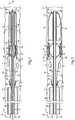
Fig. 1 is a partially sectioned side diagrammatic view of a clot retrieval system, according to one embodiment of the present disclosure, shown in a collapsed configuration;Fig. 2 is a partially sectioned side diagrammatic view of the clot retrieval system ofFig. 1 , shown in a first expanded configuration;Fig. 3 is a partially sectioned side diagrammatic view of the clot retrieval system ofFig. 1 , shown in a second expanded configuration; andFig. 4 is a partially sectioned side diagrammatic view of the clot retrieval system ofFig. 1 , shown being returned to the collapsed configuration after capturing a clot.- Referring to
Fig. 1 , there is shown aclot retrieval system 10 according to one embodiment of the present disclosure. Theclot retrieval system 10 may include a number of components, which may be provided within a sterile, tear open package, as is known in the art. In performing a clot retrieval procedure on a patient, some or all of the components of theclot retrieval system 10 may be used, depending upon the specifics of the procedure to be performed. As should be appreciated, however, the components shown inFig. 1 might be separately packaged and/or theclot retrieval system 10 might also include components in addition to those shown, including components routinely used in percutaneous vascular procedures. - The
clot retrieval system 10 has aproximal end 12 and adistal end 14, and includes anelongate shaft 16. According to the exemplary embodiment, theelongate shaft 16 may include an elongatetubular body 18 defining at least onelumen 20 extending from aproximal end 22 to adistal end 24 of the elongatetubular body 18. The elongatetubular body 18 may be made from any common medical tube material, such as, for example, polytetrafluoroethylene (PTFE), high density polyethylene (HDPE), nylon, polyetheretherketone (PEEK), or any vinyl, plastic, rubber, or silicone, and may exhibit both stiffness, or firmness, and flexibility. Materials as well as dimensions may vary depending on the particular application. In the present disclosure, "proximal" will be used to refer to the end of a component or feature that is closest to a clinician, while "distal" is used to refer to a component or feature that is farthest away from the clinician. Such meanings are consistent with conventional use of the terms and, as such, should be understood by those skilled in the art. - An
expansion device 26 is supported on theelongate shaft 16 and, according to the exemplary embodiment, may include aballoon 28, such as an inflatable balloon. As such, thelumen 20 referenced above may be an inflation lumen in fluid communication with an interior 30 of theballoon 28 via at least oneopening 32 through the elongatetubular body 18. As should be appreciated, a fluid source may be used to inflate theballoon 28 via theinflation lumen 20 andopening 32. Theexpansion device 26 may also include anexpandable stent 34 positioned over theballoon 28. Theexpandable stent 34 may be positioned and configured to radially expand responsive to expansion, or inflation, of theballoon 28 using known inflation media. Although aparticular expansion device 26 is shown, it should be appreciated that one or more alternative devices capable of providing the radial expansion described herein may be substituted for one or both of theballoon 28 and theexpandable stent 34. - The
clot retrieval system 10 also includes aninverted sleeve 36 having aclosed end 38 attached to adistal segment 40 of theelongate shaft 16 and anopen end 42. Anouter section 44 of theinverted sleeve 36 that includes theopen end 42 is folded over onto aninner section 46 of theinverted sleeve 36 that includes theclosed end 38 at a rollingfold 48. Theinverted sleeve 36 may be made from a flexible film, such as, for example, a medical grade polyethylene film. As used herein, the "inverted sleeve" 36 includes any sleeve of material capable of being folded over onto itself. As theopen end 42 is moved proximally or distally, the rollingfold 48 is similarly displaced. For example, if theopen end 42 is moved proximally, theinner section 46 may shorten, theouter section 44 may lengthen, and the rollingfold 48 may have a more proximal position relative to theelongate shaft 16. If theopen end 42 is moved distally, theouter section 44 may shorten, theinner section 46 may lengthen, and the rollingfold 48 may be moved distally. Aring 50, which is axially movable along theelongate shaft 16, may be positioned radially between the outer andinner sections inverted sleeve 36 and proximally spaced relative to the rollingfold 48 to assist in the rolling movement just described. - The
open end 42 of theinverted sleeve 36 is positioned and configured such that radial expansion of theexpansion device 26 expands theopen end 42 in a radial direction. That is, theexpansion device 26 may have an axial location, relative to longitudinal axis A, that is proximally spaced from theclosed end 38 of theinverted sleeve 36, but is aligned with or distally spaced from theopen end 42 of theinverted sleeve 36. Although not shown, one or more end stops may be provided on theelongate shaft 16 for restricting movement of theopen end 42 of theinverted sleeve 36, such as by restricting axial movement of thering 50. For example, an end stop may be positioned distally relative to thering 50 and the rollingfold 48 to restrict distal movement of thering 50 and the rollingfold 48 beyond the relative positions depicted inFig. 1 . This may also assist in providing desired initial positioning of theopen end 42 of theinverted sleeve 36 relative to theexpansion device 26. - The
clot retrieval system 10 may also include at least onetether 52 having a freeproximal end 54 positioned at theproximal end 12 of theclot retrieval system 10 and adistal end 56 attached to theopen end 42 of theinverted sleeve 36. Thetether 52 may be any metallic or non-metallic wire, string, thread, cable, cord, chain, fiber, etc. capable of proximally retracting theopen end 42 of theinverted sleeve 36. The one ormore tethers 52 may pass through acone 58 supported on theelongate shaft 16. Thecone 58 has adistal end 60 that is outwardly expanded, or radially expanded, relative to aproximal end 62 of thecone 58. Thecone 58 may be proximally spaced relative to theexpansion device 26 and may be stationary relative to theelongate shaft 16. Thecone 58 may have at least oneopening 64 or passage for receiving the one ormore tethers 52 therethrough. - The
elongate shaft 16 may be used in combination with adelivery catheter 66 defining alumen 68 and having proximal anddistal ends elongate shaft 16, and additional components described herein, may be configured for receipt within thedelivery catheter 66. One or both of thedelivery catheter 66 and theelongate shaft 16 may be configured for advancement through a vascular structureV of a patient over awire guide 74 to gain access and provide proper placement of theclot retrieval system 10. For example, thedelivery catheter 66 may be advanced over thewire guide 74, and then thewire guide 74 may be replaced with theelongate shaft 16. Alternatively, and as shown, thedelivery catheter 66 andelongate shaft 16 may be advanced over thewire guide 74 and, more specifically, thewire guide 74 may be received within a lumen, such aslumen 20, of theelongate shaft 16. It should be appreciated that, according to some embodiments, theelongate shaft 16 may include separate inflation and wire guide lumens. - Although not shown, a handle may be provided at the
proximal end 12 of theclot retrieval system 10. The handle may be attached to any one or more of theelongate shaft 16, thedelivery catheter 66, and the one ormore tethers 52 and may be used to facilitate relative movement of the components during a clot retrieval procedure. For example, to achieve the positioning and placement shown inFig. 1 , theelongate shaft 16 may be advanced distally beyond the opendistal end 72 of thedelivery catheter 66. Theclot retrieval system 10 may be initially provided in a collapsed configuration in which theexpansion device 26 is collapsed, theopen end 42 of theinverted sleeve 36 is collapsed, and the rollingfold 48 is at a first position. - The
clot retrieval system 10 also has a first expanded configuration in which theexpansion device 26 is radially expanded and theopen end 42 of theinverted sleeve 36 is radially expanded, as shown inFig. 2 . According to the exemplary embodiment, theballoon 28 may be radially expanded and theexpandable stent 34 may be radially expanded to achieve the first expanded configuration of theclot retrieval system 10. According to some embodiments, theopen end 42 of theinverted sleeve 36 may be radially expanded to substantially match the inner diameter of the vascular structureV in which theclot retrieval system 10 is positioned. - As will be described below, the
expansion device 26 and theopen end 42 of theinverted sleeve 36 may be positioned distally relative to a clot C while theclot retrieval system 10 is positioned in the collapsed configuration. After transition of theclot retrieval system 10 to the first expanded configuration, theclot retrieval system 10 may be moved to a second expanded configuration, as shown inFig. 3 . According to the second expanded configuration, theexpansion device 26 andopen end 42 of theinverted sleeve 36 remain radially expanded, and theopen end 42 of theinverted sleeve 36 and the rollingfold 48 are proximally retracted. According to the second expanded configuration, the clot C is positioned radially between theelongate shaft 16 and theouter section 44 of theinverted sleeve 36. - The
expansion device 26 may then be collapsed, as shown inFig. 4 . For example, theballoon 28 may be collapsed, or deflated, in a manner known to those skilled in the art. During retraction of theopen end 42 of theinverted sleeve 36, the one ormore tethers 52 may be pulled through thecone 58 to assist in collapsing theexpandable stent 34. That is, the one ormore tethers 52 and, thus, theexpandable stent 34, may be pulled in close proximity to theelongate shaft 16 using thecone 58. With theexpansion device 26 collapsed and theopen end 42 of theinverted sleeve 36 pulled radially inward to envelope the clot C, theelongate shaft 16 may be proximally retracted into thedelivery catheter 66. Theclot retrieval system 10 and clot C may then be removed from the patient. - Referring generally to
Figs. 1-4 , an exemplary percutaneous vascular procedure using theclot retrieval system 10 of the present disclosure will be discussed with reference to a vascular structureV of a patient. The vascular structureV, as should be appreciated, may include a vessel wall defining a lumen and may have a region of blockage. That is, the region may include one or more clotsC. A clinician may first use an introducer needle and wire guide 74 to gain access to the vascular structureV and position an introducer sheath in a known manner. Thereafter, theclot retrieval system 10 may be advanced over thewire guide 74 and toward the region of blockage. In particular, theclot retrieval system 10 may be advanced in the collapsed configuration such that theopen end 42 of theinverted sleeve 36, theexpansion device 26, and the rollingfold 48 are distally spaced from the clotC, as shown inFig. 1 . According to some procedures, thewire guide 74 and theelongate shaft 16 may be used to cross the clotC. - Next, as shown in
Fig. 2 , theclot retrieval system 10 may be moved from the collapsed configuration to the first expanded configuration. In particular, theballoon 28 andexpandable stent 34 may be radially expanded to radially expand theopen end 42 of theinverted sleeve 36. With theopen end 42 fully expanded, the one ormore tethers 52, or other suitable devices, may be proximally retracted to proximally retract theopen end 42 of theinverted sleeve 36 over the clotC to move theclot retrieval system 10 to the second expanded configuration. According to the second expanded configuration, theopen end 42 of theinverted sleeve 36, the rollingfold 48, and thering 50 are all proximally retracted and the clotC is captured using theinverted sleeve 36. - The clotC may be removed from the patient by transitioning the
clot retrieval system 10 back into the collapsed configuration and removing theclot retrieval system 10 from the patient. For example, theballoon 28 may be deflated and theexpandable stent 34 may be collapsed to provide a lower profile of theelongate shaft 16. In addition, collapsing theopen end 42 of theinverted sleeve 36 back toward theelongate shaft 16 may assist in capturing the clot C between theouter section 44 of theinverted sleeve 36 and theelongate shaft 16. - It may be desirable to use a non-porous material for the
inverted sleeve 36 so that no portions of the clotC may pass through theinverted sleeve 36. After capturing the clotC, theelongate shaft 16 may be proximally retracted into thedelivery catheter 66 and theclot retrieval system 10 may be withdrawn from the vascular structureV. - The
clot retrieval system 10 of the present disclosure may provide a relatively low profile and effective means for capturing and removing clotsC from the vasculature of a patient. In particular, theclot retrieval system 10 disclosed herein may completely envelope the clotsC in a confined space during retrieval from the patient, where conventional devices and systems often risk incomplete retrieval of clots or clot fragments. - It should be understood that the above description is intended for illustrative purposes only, and is not intended to limit the scope of the present disclosure in any way. Thus, those skilled in the art will appreciate that other aspects of the disclosure can be obtained from a study of the drawings, the disclosure and the appended claims.
Claims (10)
- A clot retrieval system (10), comprising:a delivery catheter (66) defining a lumen and having proximal and distal ends;an elongate shaft (16) having proximal and distal ends and configured for receipt within the delivery catheter;an inverted sleeve (36) having a closed end (38) attached to a distal segment of the elongate shaft and an open end (42), andan expansion device (26) supported on the elongate shaft at an axial location;characterized in that:an outer section of the inverted sleeve including the open end is folded over onto an inner section of the inverted sleeve including the closed end at a rolling fold (48); andthe expansion device is supported on the elongate shaft at a location proximally spaced from the closed end and aligned with or distally spaced from the open end, wherein the expansion device is configured for radially expanding the open end of the inverted sleeve.
- The clot retrieval system of claim 1, wherein the expansion device includes a balloon (28).
- The clot retrieval system of claim 2, wherein the elongate shaft defines an inflation lumen (20) in fluid communication with an interior of the balloon.
- The clot retrieval system of claim 1 or claim 2, wherein the expansion device further includes an expandable stent (34) positioned over the balloon.
- The clot retrieval system of any one of the preceding claims, further including at least one tether (52) having a free proximal end positioned at a proximal end of the clot retrieval system and a distal end attached to the open end of the inverted sleeve.
- The clot retrieval system of claim 5, further including a cone (58) supported on the elongate shaft and having a distal end that is outwardly expanded relative to a proximal end of the cone, wherein the cone is proximally spaced relative to the expansion device and is configured to receive the tether.
- The clot retrieval system of any one of the preceding claims, further including a ring (50) axially movable along the elongate shaft, wherein the ring is positioned radially between the inner and outer sections of the inverted sleeve and is proximally spaced relative to the rolling fold.
- The clot retrieval system of claim 7, wherein the clot retrieval system has:a collapsed configuration in which the expansion device is collapsed, the open end of the inverted sleeve is collapsed, and the rolling fold is at a first position; andan expanded configuration in which the expansion device is radially expanded, the open end of the inverted sleeve is radially expanded, and the rolling fold is proximally spaced relative to the first position.
- The clot retrieval system of any one of the preceding claims, wherein the inverted sleeve is non-porous.
- The clot retrieval system of any one of the preceding claims, wherein the elongate shaft (16) includes a lumen configured for advancement over a wire guide.
Applications Claiming Priority (1)
| Application Number | Priority Date | Filing Date | Title |
|---|---|---|---|
| US201361881633P | 2013-09-24 | 2013-09-24 |
Publications (2)
| Publication Number | Publication Date |
|---|---|
| EP2851016A1 EP2851016A1 (en) | 2015-03-25 |
| EP2851016B1true EP2851016B1 (en) | 2020-01-01 |
Family
ID=51357825
Family Applications (1)
| Application Number | Title | Priority Date | Filing Date |
|---|---|---|---|
| EP14181317.0AActiveEP2851016B1 (en) | 2013-09-24 | 2014-08-18 | Clot retrieval system with inverted sleeve |
Country Status (2)
| Country | Link |
|---|---|
| US (1) | US9814477B2 (en) |
| EP (1) | EP2851016B1 (en) |
Families Citing this family (36)
| Publication number | Priority date | Publication date | Assignee | Title |
|---|---|---|---|---|
| US7686825B2 (en) | 2004-03-25 | 2010-03-30 | Hauser David L | Vascular filter device |
| US8784434B2 (en) | 2012-11-20 | 2014-07-22 | Inceptus Medical, Inc. | Methods and apparatus for treating embolism |
| US10238406B2 (en) | 2013-10-21 | 2019-03-26 | Inari Medical, Inc. | Methods and apparatus for treating embolism |
| US9999493B2 (en) | 2015-08-06 | 2018-06-19 | Kp Medcure, Inc. | Axial lengthening thrombus capture system |
| US9579116B1 (en) | 2015-08-06 | 2017-02-28 | Kp Medcure, Inc. | Axial lengthening thrombus capture system |
| US9744024B2 (en) | 2015-08-06 | 2017-08-29 | Kp Medcure, Inc. | Axial lengthening thrombus capture system |
| CN108348319B (en) | 2015-09-28 | 2020-03-10 | 斯瑞克公司 | Mechanical embolectomy device and method |
| CN113796927B (en) | 2015-10-23 | 2025-03-04 | 伊纳里医疗公司 | Intravascular treatment of vascular occlusion and related devices, systems and methods |
| US10376678B2 (en)* | 2016-01-08 | 2019-08-13 | Makaha Medical, Llc. | Systems and methods for controlling reperfusion in a vessel |
| US10595818B2 (en) | 2016-03-19 | 2020-03-24 | Makaha Medical, Llc. | Medical systems and methods for density assessment using ultrasound |
| US11076808B2 (en) | 2016-03-26 | 2021-08-03 | Makaha Medical, LLC | Flexible medical device with marker band and sensor |
| US11497512B2 (en) | 2016-04-25 | 2022-11-15 | Stryker Corporation | Inverting thrombectomy apparatuses and methods |
| EP3590446B1 (en) | 2016-04-25 | 2021-01-06 | Stryker Corporation | Anti-jamming and macerating thrombectomy apparatuses |
| EP3448276B1 (en)* | 2016-04-25 | 2020-03-04 | Stryker Corporation | Clot-engulfing mechanical thrombectomy apparatuses |
| US11896247B2 (en) | 2016-04-25 | 2024-02-13 | Stryker Corporation | Inverting mechanical thrombectomy apparatuses |
| WO2017189591A1 (en) | 2016-04-25 | 2017-11-02 | Stryker Corporation | Inverting mechanical thrombectomy apparatuses and methods of use in the vasculature |
| CN109561903B (en) | 2016-06-03 | 2021-07-27 | 斯瑞克公司 | Flip thrombectomy device |
| WO2018049317A1 (en) | 2016-09-12 | 2018-03-15 | Stryker Corporation | Self-rolling thrombectomy apparatuses and methods |
| FI3528717T3 (en) | 2016-10-24 | 2024-08-09 | Inari Medical Inc | Devices for treating vascular occlusion |
| WO2019050765A1 (en) | 2017-09-06 | 2019-03-14 | Inari Medical, Inc. | Hemostasis valves and methods of use |
| EP4176830A1 (en) | 2017-11-09 | 2023-05-10 | Stryker Corporation | Inverting thrombectomy apparatuses having enhanced tracking |
| US11154314B2 (en) | 2018-01-26 | 2021-10-26 | Inari Medical, Inc. | Single insertion delivery system for treating embolism and associated systems and methods |
| WO2019222117A1 (en) | 2018-05-14 | 2019-11-21 | Stryker Corporation | Inverting thrombectomy apparatuses and methods of use |
| CA3114285A1 (en) | 2018-08-13 | 2020-02-20 | Inari Medical, Inc. | System for treating embolism and associated devices and methods |
| CN112969420B (en) | 2018-09-10 | 2024-12-17 | 史赛克公司 | Inverted thrombectomy device and method of using thrombectomy device |
| CN112702961A (en) | 2018-09-10 | 2021-04-23 | 斯瑞克公司 | Laser grooving and grabbing device |
| KR102829457B1 (en)* | 2019-02-08 | 2025-07-04 | 주식회사 엔벤트릭 | Device and method for removing occlusive clot |
| WO2020214971A1 (en)* | 2019-04-19 | 2020-10-22 | Cruzar Medsystems, Inc. | Endoscopic cannula for fallopian tube access |
| US11607234B2 (en) | 2019-06-11 | 2023-03-21 | Cruzar Medsystems, Inc. | Systems and methods for traversing a site of obstruction |
| JP7638273B2 (en) | 2019-10-16 | 2025-03-03 | イナリ メディカル, インコーポレイテッド | Systems, devices and methods for treating vascular obstructions |
| CN115175638B (en) | 2019-11-05 | 2025-09-26 | 瓦斯科尔勒治疗股份有限公司 | Axially extended thrombus capture system, tensioning system, and expandable funnel catheter |
| CN115916075A (en) | 2020-01-30 | 2023-04-04 | 尤利耶尔医疗股份公司 | Device and method for neurovascular endoluminal intervention |
| EP4463083A1 (en) | 2022-01-11 | 2024-11-20 | Inari Medical, Inc. | Devices for removing clot material from intravascularly implanted devices, and associated systems and methods |
| US11737767B2 (en) | 2022-01-21 | 2023-08-29 | Julier Medical AG | Neurovascular catheter and method of use |
| WO2023147460A1 (en) | 2022-01-27 | 2023-08-03 | Contego Medical, Inc. | Thrombectomy and aspiration system and methods of use |
| US12226112B1 (en) | 2023-12-15 | 2025-02-18 | Cerebrova KP Medical, Inc. | Neurovascular clot retrieving system |
Family Cites Families (18)
| Publication number | Priority date | Publication date | Assignee | Title |
|---|---|---|---|---|
| US6210370B1 (en)* | 1997-01-10 | 2001-04-03 | Applied Medical Resources Corporation | Access device with expandable containment member |
| EP1028670B1 (en) | 1997-11-07 | 2008-01-02 | Salviac Limited | An embolic protection device |
| US6840950B2 (en) | 2001-02-20 | 2005-01-11 | Scimed Life Systems, Inc. | Low profile emboli capture device |
| US6890340B2 (en)* | 2001-11-29 | 2005-05-10 | Medtronic Vascular, Inc. | Apparatus for temporary intraluminal protection |
| US6837898B2 (en)* | 2001-11-30 | 2005-01-04 | Advanced Cardiovascular Systems, Inc. | Intraluminal delivery system for an attachable treatment device |
| DE60315425T2 (en)* | 2002-03-05 | 2008-06-26 | Salviac Ltd. | SYSTEM FOR PROTECTION FROM EMBOLICS |
| US20030176884A1 (en) | 2002-03-12 | 2003-09-18 | Marwane Berrada | Everted filter device |
| US7722634B2 (en)* | 2003-07-03 | 2010-05-25 | Regents Of The University Of Minnesota | Medical device and method of intravenous filtration |
| US7462183B2 (en) | 2004-07-07 | 2008-12-09 | Percutaneous Systems, Inc. | Methods for deploying conformed structures in body lumens |
| US20070088382A1 (en) | 2005-10-13 | 2007-04-19 | Bei Nianjiong J | Embolic protection recovery catheter assembly |
| US20070288054A1 (en) | 2006-06-13 | 2007-12-13 | Tanaka Don A | Vascular thrombectomby apparatus and method of use |
| US8545526B2 (en) | 2007-12-26 | 2013-10-01 | Lazarus Effect, Inc. | Retrieval systems and methods for use thereof |
| US20090287193A1 (en) | 2008-05-16 | 2009-11-19 | Percutaneous Systems, Inc. | Systems and methods for stone removal |
| US20100249815A1 (en) | 2009-03-25 | 2010-09-30 | Cook Incorporated | Everted sheath thrombectomy device |
| US8926559B2 (en) | 2010-10-06 | 2015-01-06 | Cruzer Medsystems, Inc. | Catheter with vessel lining and methods for using same |
| WO2012049652A1 (en) | 2010-10-15 | 2012-04-19 | Endogrowth (Proprietary) Limited | An inversible tubular member and a gripping device including such a member |
| ES2683178T3 (en) | 2011-05-23 | 2018-09-25 | Covidien Lp | Extraction systems |
| US10010437B2 (en)* | 2011-10-17 | 2018-07-03 | W. L. Gore & Associates, Inc. | Endoluminal device retrieval devices and related systems and methods |
- 2014
- 2014-08-07USUS14/454,039patent/US9814477B2/enactiveActive
- 2014-08-18EPEP14181317.0Apatent/EP2851016B1/enactiveActive
Non-Patent Citations (1)
| Title |
|---|
| None* |
Also Published As
| Publication number | Publication date |
|---|---|
| US20150088190A1 (en) | 2015-03-26 |
| US9814477B2 (en) | 2017-11-14 |
| EP2851016A1 (en) | 2015-03-25 |
Similar Documents
| Publication | Publication Date | Title |
|---|---|---|
| EP2851016B1 (en) | Clot retrieval system with inverted sleeve | |
| US11266434B2 (en) | Introducer sheaths, thrombus collection devices, and associated methods | |
| US20210220007A1 (en) | Intravascular catheter having an expandable incising portion | |
| US10098651B2 (en) | Devices and methods for treating vascular occlusion | |
| US7909862B2 (en) | Delivery systems and methods for deploying expandable intraluminal medical devices | |
| US9107736B2 (en) | Highly trackable balloon catheter system and method for collapsing an expanded medical device | |
| ITMI20130816A1 (en) | DEVICE TO INTRODUCE WITH EXPANDABLE ENDS | |
| JP2007508903A (en) | Deployable balloon catheter for preventing proximal emboli | |
| WO2020132505A2 (en) | Apparatus and method for implanting an arteriovenous graft | |
| US20100016792A1 (en) | Collecting sheath and method of use thereof | |
| WO2009120173A2 (en) | Embolectomy catheter | |
| JP2009542302A (en) | Collecting sheath and method of using the same | |
| US20220233204A1 (en) | Anchoring and Non-Occluding Intravascular Device for Use During Clot Removal Via Aspiration and/or Mechanical Extraction Device | |
| JP2020022752A (en) | Stent delivery with expansion assisting delivery wire | |
| US20220378463A1 (en) | Intravascular catheter having an expandable incising portion and embolic protection device | |
| EP3932341B1 (en) | Intravascular plaque isolation, destabilization, and aspiration | |
| US12433598B2 (en) | Thrombus aspiration systems and related methods | |
| JP6506130B2 (en) | Catheter with vascular lining and method of using the same | |
| US20180125687A1 (en) | Retrieval of medical devices | |
| US20220110647A1 (en) | Thrombus Aspiration Systems and Related Methods | |
| US20120172914A1 (en) | Occlusion device | |
| US9498364B2 (en) | Medical device delivery system and method of flushing same | |
| US20220378566A1 (en) | Intravascular catheter having an expandable incising portion and embolic protection device | |
| JP2025515799A (en) | Apparatus for dilating biological tissue | |
| CN117582264A (en) | Intravascular catheter with expandable incision portion and embolic protection device |
Legal Events
| Date | Code | Title | Description |
|---|---|---|---|
| PUAI | Public reference made under article 153(3) epc to a published international application that has entered the european phase | Free format text:ORIGINAL CODE: 0009012 | |
| 17P | Request for examination filed | Effective date:20140818 | |
| AK | Designated contracting states | Kind code of ref document:A1 Designated state(s):AL AT BE BG CH CY CZ DE DK EE ES FI FR GB GR HR HU IE IS IT LI LT LU LV MC MK MT NL NO PL PT RO RS SE SI SK SM TR | |
| AX | Request for extension of the european patent | Extension state:BA ME | |
| R17P | Request for examination filed (corrected) | Effective date:20150619 | |
| RBV | Designated contracting states (corrected) | Designated state(s):AL AT BE BG CH CY CZ DE DK EE ES FI FR GB GR HR HU IE IS IT LI LT LU LV MC MK MT NL NO PL PT RO RS SE SI SK SM TR | |
| REG | Reference to a national code | Ref country code:DE Ref legal event code:R079 Ref document number:602014059188 Country of ref document:DE Free format text:PREVIOUS MAIN CLASS: A61B0017220000 Ipc:A61F0002010000 | |
| GRAP | Despatch of communication of intention to grant a patent | Free format text:ORIGINAL CODE: EPIDOSNIGR1 | |
| STAA | Information on the status of an ep patent application or granted ep patent | Free format text:STATUS: GRANT OF PATENT IS INTENDED | |
| RIC1 | Information provided on ipc code assigned before grant | Ipc:A61B 17/22 20060101ALI20190626BHEP Ipc:A61B 17/12 20060101ALI20190626BHEP Ipc:A61F 2/01 20060101AFI20190626BHEP Ipc:A61B 17/3207 20060101ALI20190626BHEP | |
| INTG | Intention to grant announced | Effective date:20190724 | |
| GRAS | Grant fee paid | Free format text:ORIGINAL CODE: EPIDOSNIGR3 | |
| GRAA | (expected) grant | Free format text:ORIGINAL CODE: 0009210 | |
| STAA | Information on the status of an ep patent application or granted ep patent | Free format text:STATUS: THE PATENT HAS BEEN GRANTED | |
| AK | Designated contracting states | Kind code of ref document:B1 Designated state(s):AL AT BE BG CH CY CZ DE DK EE ES FI FR GB GR HR HU IE IS IT LI LT LU LV MC MK MT NL NO PL PT RO RS SE SI SK SM TR | |
| REG | Reference to a national code | Ref country code:GB Ref legal event code:FG4D | |
| REG | Reference to a national code | Ref country code:AT Ref legal event code:REF Ref document number:1218838 Country of ref document:AT Kind code of ref document:T Effective date:20200115 Ref country code:CH Ref legal event code:EP | |
| REG | Reference to a national code | Ref country code:DE Ref legal event code:R096 Ref document number:602014059188 Country of ref document:DE | |
| REG | Reference to a national code | Ref country code:IE Ref legal event code:FG4D | |
| REG | Reference to a national code | Ref country code:NL Ref legal event code:MP Effective date:20200101 | |
| REG | Reference to a national code | Ref country code:LT Ref legal event code:MG4D | |
| PG25 | Lapsed in a contracting state [announced via postgrant information from national office to epo] | Ref country code:PT Free format text:LAPSE BECAUSE OF FAILURE TO SUBMIT A TRANSLATION OF THE DESCRIPTION OR TO PAY THE FEE WITHIN THE PRESCRIBED TIME-LIMIT Effective date:20200527 Ref country code:CZ Free format text:LAPSE BECAUSE OF FAILURE TO SUBMIT A TRANSLATION OF THE DESCRIPTION OR TO PAY THE FEE WITHIN THE PRESCRIBED TIME-LIMIT Effective date:20200101 Ref country code:RS Free format text:LAPSE BECAUSE OF FAILURE TO SUBMIT A TRANSLATION OF THE DESCRIPTION OR TO PAY THE FEE WITHIN THE PRESCRIBED TIME-LIMIT Effective date:20200101 Ref country code:NL Free format text:LAPSE BECAUSE OF FAILURE TO SUBMIT A TRANSLATION OF THE DESCRIPTION OR TO PAY THE FEE WITHIN THE PRESCRIBED TIME-LIMIT Effective date:20200101 Ref country code:FI Free format text:LAPSE BECAUSE OF FAILURE TO SUBMIT A TRANSLATION OF THE DESCRIPTION OR TO PAY THE FEE WITHIN THE PRESCRIBED TIME-LIMIT Effective date:20200101 Ref country code:LT Free format text:LAPSE BECAUSE OF FAILURE TO SUBMIT A TRANSLATION OF THE DESCRIPTION OR TO PAY THE FEE WITHIN THE PRESCRIBED TIME-LIMIT Effective date:20200101 Ref country code:NO Free format text:LAPSE BECAUSE OF FAILURE TO SUBMIT A TRANSLATION OF THE DESCRIPTION OR TO PAY THE FEE WITHIN THE PRESCRIBED TIME-LIMIT Effective date:20200401 | |
| PG25 | Lapsed in a contracting state [announced via postgrant information from national office to epo] | Ref country code:HR Free format text:LAPSE BECAUSE OF FAILURE TO SUBMIT A TRANSLATION OF THE DESCRIPTION OR TO PAY THE FEE WITHIN THE PRESCRIBED TIME-LIMIT Effective date:20200101 Ref country code:GR Free format text:LAPSE BECAUSE OF FAILURE TO SUBMIT A TRANSLATION OF THE DESCRIPTION OR TO PAY THE FEE WITHIN THE PRESCRIBED TIME-LIMIT Effective date:20200402 Ref country code:SE Free format text:LAPSE BECAUSE OF FAILURE TO SUBMIT A TRANSLATION OF THE DESCRIPTION OR TO PAY THE FEE WITHIN THE PRESCRIBED TIME-LIMIT Effective date:20200101 Ref country code:LV Free format text:LAPSE BECAUSE OF FAILURE TO SUBMIT A TRANSLATION OF THE DESCRIPTION OR TO PAY THE FEE WITHIN THE PRESCRIBED TIME-LIMIT Effective date:20200101 Ref country code:IS Free format text:LAPSE BECAUSE OF FAILURE TO SUBMIT A TRANSLATION OF THE DESCRIPTION OR TO PAY THE FEE WITHIN THE PRESCRIBED TIME-LIMIT Effective date:20200501 Ref country code:BG Free format text:LAPSE BECAUSE OF FAILURE TO SUBMIT A TRANSLATION OF THE DESCRIPTION OR TO PAY THE FEE WITHIN THE PRESCRIBED TIME-LIMIT Effective date:20200401 | |
| REG | Reference to a national code | Ref country code:DE Ref legal event code:R097 Ref document number:602014059188 Country of ref document:DE | |
| PG25 | Lapsed in a contracting state [announced via postgrant information from national office to epo] | Ref country code:RO Free format text:LAPSE BECAUSE OF FAILURE TO SUBMIT A TRANSLATION OF THE DESCRIPTION OR TO PAY THE FEE WITHIN THE PRESCRIBED TIME-LIMIT Effective date:20200101 Ref country code:ES Free format text:LAPSE BECAUSE OF FAILURE TO SUBMIT A TRANSLATION OF THE DESCRIPTION OR TO PAY THE FEE WITHIN THE PRESCRIBED TIME-LIMIT Effective date:20200101 Ref country code:EE Free format text:LAPSE BECAUSE OF FAILURE TO SUBMIT A TRANSLATION OF THE DESCRIPTION OR TO PAY THE FEE WITHIN THE PRESCRIBED TIME-LIMIT Effective date:20200101 Ref country code:SM Free format text:LAPSE BECAUSE OF FAILURE TO SUBMIT A TRANSLATION OF THE DESCRIPTION OR TO PAY THE FEE WITHIN THE PRESCRIBED TIME-LIMIT Effective date:20200101 Ref country code:DK Free format text:LAPSE BECAUSE OF FAILURE TO SUBMIT A TRANSLATION OF THE DESCRIPTION OR TO PAY THE FEE WITHIN THE PRESCRIBED TIME-LIMIT Effective date:20200101 Ref country code:SK Free format text:LAPSE BECAUSE OF FAILURE TO SUBMIT A TRANSLATION OF THE DESCRIPTION OR TO PAY THE FEE WITHIN THE PRESCRIBED TIME-LIMIT Effective date:20200101 | |
| PLBE | No opposition filed within time limit | Free format text:ORIGINAL CODE: 0009261 | |
| STAA | Information on the status of an ep patent application or granted ep patent | Free format text:STATUS: NO OPPOSITION FILED WITHIN TIME LIMIT | |
| REG | Reference to a national code | Ref country code:AT Ref legal event code:MK05 Ref document number:1218838 Country of ref document:AT Kind code of ref document:T Effective date:20200101 | |
| 26N | No opposition filed | Effective date:20201002 | |
| PG25 | Lapsed in a contracting state [announced via postgrant information from national office to epo] | Ref country code:IT Free format text:LAPSE BECAUSE OF FAILURE TO SUBMIT A TRANSLATION OF THE DESCRIPTION OR TO PAY THE FEE WITHIN THE PRESCRIBED TIME-LIMIT Effective date:20200101 Ref country code:AT Free format text:LAPSE BECAUSE OF FAILURE TO SUBMIT A TRANSLATION OF THE DESCRIPTION OR TO PAY THE FEE WITHIN THE PRESCRIBED TIME-LIMIT Effective date:20200101 | |
| PG25 | Lapsed in a contracting state [announced via postgrant information from national office to epo] | Ref country code:SI Free format text:LAPSE BECAUSE OF FAILURE TO SUBMIT A TRANSLATION OF THE DESCRIPTION OR TO PAY THE FEE WITHIN THE PRESCRIBED TIME-LIMIT Effective date:20200101 Ref country code:PL Free format text:LAPSE BECAUSE OF FAILURE TO SUBMIT A TRANSLATION OF THE DESCRIPTION OR TO PAY THE FEE WITHIN THE PRESCRIBED TIME-LIMIT Effective date:20200101 | |
| PG25 | Lapsed in a contracting state [announced via postgrant information from national office to epo] | Ref country code:MC Free format text:LAPSE BECAUSE OF FAILURE TO SUBMIT A TRANSLATION OF THE DESCRIPTION OR TO PAY THE FEE WITHIN THE PRESCRIBED TIME-LIMIT Effective date:20200101 | |
| REG | Reference to a national code | Ref country code:CH Ref legal event code:PL | |
| PG25 | Lapsed in a contracting state [announced via postgrant information from national office to epo] | Ref country code:LU Free format text:LAPSE BECAUSE OF NON-PAYMENT OF DUE FEES Effective date:20200818 Ref country code:CH Free format text:LAPSE BECAUSE OF NON-PAYMENT OF DUE FEES Effective date:20200831 Ref country code:LI Free format text:LAPSE BECAUSE OF NON-PAYMENT OF DUE FEES Effective date:20200831 | |
| REG | Reference to a national code | Ref country code:BE Ref legal event code:MM Effective date:20200831 | |
| PG25 | Lapsed in a contracting state [announced via postgrant information from national office to epo] | Ref country code:FR Free format text:LAPSE BECAUSE OF NON-PAYMENT OF DUE FEES Effective date:20200831 | |
| PG25 | Lapsed in a contracting state [announced via postgrant information from national office to epo] | Ref country code:BE Free format text:LAPSE BECAUSE OF NON-PAYMENT OF DUE FEES Effective date:20200831 | |
| PG25 | Lapsed in a contracting state [announced via postgrant information from national office to epo] | Ref country code:TR Free format text:LAPSE BECAUSE OF FAILURE TO SUBMIT A TRANSLATION OF THE DESCRIPTION OR TO PAY THE FEE WITHIN THE PRESCRIBED TIME-LIMIT Effective date:20200101 Ref country code:MT Free format text:LAPSE BECAUSE OF FAILURE TO SUBMIT A TRANSLATION OF THE DESCRIPTION OR TO PAY THE FEE WITHIN THE PRESCRIBED TIME-LIMIT Effective date:20200101 Ref country code:CY Free format text:LAPSE BECAUSE OF FAILURE TO SUBMIT A TRANSLATION OF THE DESCRIPTION OR TO PAY THE FEE WITHIN THE PRESCRIBED TIME-LIMIT Effective date:20200101 | |
| PG25 | Lapsed in a contracting state [announced via postgrant information from national office to epo] | Ref country code:MK Free format text:LAPSE BECAUSE OF FAILURE TO SUBMIT A TRANSLATION OF THE DESCRIPTION OR TO PAY THE FEE WITHIN THE PRESCRIBED TIME-LIMIT Effective date:20200101 Ref country code:AL Free format text:LAPSE BECAUSE OF FAILURE TO SUBMIT A TRANSLATION OF THE DESCRIPTION OR TO PAY THE FEE WITHIN THE PRESCRIBED TIME-LIMIT Effective date:20200101 | |
| P01 | Opt-out of the competence of the unified patent court (upc) registered | Effective date:20230602 | |
| PGFP | Annual fee paid to national office [announced via postgrant information from national office to epo] | Ref country code:DE Payment date:20240625 Year of fee payment:11 Ref country code:IE Payment date:20240726 Year of fee payment:11 | |
| PGFP | Annual fee paid to national office [announced via postgrant information from national office to epo] | Ref country code:GB Payment date:20240711 Year of fee payment:11 |