EP2850501B1 - Information control system - Google Patents
Information control systemDownload PDFInfo
- Publication number
- EP2850501B1 EP2850501B1EP13790120.3AEP13790120AEP2850501B1EP 2850501 B1EP2850501 B1EP 2850501B1EP 13790120 AEP13790120 AEP 13790120AEP 2850501 B1EP2850501 B1EP 2850501B1
- Authority
- EP
- European Patent Office
- Prior art keywords
- monitored space
- mobile device
- application server
- environmental attribute
- time
- Prior art date
- Legal status (The legal status is an assumption and is not a legal conclusion. Google has not performed a legal analysis and makes no representation as to the accuracy of the status listed.)
- Active
Links
Images


Classifications
- F—MECHANICAL ENGINEERING; LIGHTING; HEATING; WEAPONS; BLASTING
- F24—HEATING; RANGES; VENTILATING
- F24F—AIR-CONDITIONING; AIR-HUMIDIFICATION; VENTILATION; USE OF AIR CURRENTS FOR SCREENING
- F24F11/00—Control or safety arrangements
- G—PHYSICS
- G05—CONTROLLING; REGULATING
- G05D—SYSTEMS FOR CONTROLLING OR REGULATING NON-ELECTRIC VARIABLES
- G05D23/00—Control of temperature
- G05D23/19—Control of temperature characterised by the use of electric means
- G05D23/1951—Control of temperature characterised by the use of electric means with control of the working time of a temperature controlling device
- G—PHYSICS
- G05—CONTROLLING; REGULATING
- G05D—SYSTEMS FOR CONTROLLING OR REGULATING NON-ELECTRIC VARIABLES
- G05D23/00—Control of temperature
- G05D23/19—Control of temperature characterised by the use of electric means
- G—PHYSICS
- G01—MEASURING; TESTING
- G01S—RADIO DIRECTION-FINDING; RADIO NAVIGATION; DETERMINING DISTANCE OR VELOCITY BY USE OF RADIO WAVES; LOCATING OR PRESENCE-DETECTING BY USE OF THE REFLECTION OR RERADIATION OF RADIO WAVES; ANALOGOUS ARRANGEMENTS USING OTHER WAVES
- G01S5/00—Position-fixing by co-ordinating two or more direction or position line determinations; Position-fixing by co-ordinating two or more distance determinations
- G—PHYSICS
- G05—CONTROLLING; REGULATING
- G05B—CONTROL OR REGULATING SYSTEMS IN GENERAL; FUNCTIONAL ELEMENTS OF SUCH SYSTEMS; MONITORING OR TESTING ARRANGEMENTS FOR SUCH SYSTEMS OR ELEMENTS
- G05B15/00—Systems controlled by a computer
- G05B15/02—Systems controlled by a computer electric
- G—PHYSICS
- G05—CONTROLLING; REGULATING
- G05D—SYSTEMS FOR CONTROLLING OR REGULATING NON-ELECTRIC VARIABLES
- G05D1/00—Control of position, course, altitude or attitude of land, water, air or space vehicles, e.g. using automatic pilots
- G—PHYSICS
- G06—COMPUTING OR CALCULATING; COUNTING
- G06Q—INFORMATION AND COMMUNICATION TECHNOLOGY [ICT] SPECIALLY ADAPTED FOR ADMINISTRATIVE, COMMERCIAL, FINANCIAL, MANAGERIAL OR SUPERVISORY PURPOSES; SYSTEMS OR METHODS SPECIALLY ADAPTED FOR ADMINISTRATIVE, COMMERCIAL, FINANCIAL, MANAGERIAL OR SUPERVISORY PURPOSES, NOT OTHERWISE PROVIDED FOR
- G06Q10/00—Administration; Management
- G—PHYSICS
- G06—COMPUTING OR CALCULATING; COUNTING
- G06Q—INFORMATION AND COMMUNICATION TECHNOLOGY [ICT] SPECIALLY ADAPTED FOR ADMINISTRATIVE, COMMERCIAL, FINANCIAL, MANAGERIAL OR SUPERVISORY PURPOSES; SYSTEMS OR METHODS SPECIALLY ADAPTED FOR ADMINISTRATIVE, COMMERCIAL, FINANCIAL, MANAGERIAL OR SUPERVISORY PURPOSES, NOT OTHERWISE PROVIDED FOR
- G06Q50/00—Information and communication technology [ICT] specially adapted for implementation of business processes of specific business sectors, e.g. utilities or tourism
- G06Q50/10—Services
- G06Q50/12—Hotels or restaurants
- H—ELECTRICITY
- H04—ELECTRIC COMMUNICATION TECHNIQUE
- H04Q—SELECTING
- H04Q9/00—Arrangements in telecontrol or telemetry systems for selectively calling a substation from a main station, in which substation desired apparatus is selected for applying a control signal thereto or for obtaining measured values therefrom
- H—ELECTRICITY
- H04—ELECTRIC COMMUNICATION TECHNIQUE
- H04W—WIRELESS COMMUNICATION NETWORKS
- H04W4/00—Services specially adapted for wireless communication networks; Facilities therefor
- H04W4/02—Services making use of location information
- H—ELECTRICITY
- H04—ELECTRIC COMMUNICATION TECHNIQUE
- H04W—WIRELESS COMMUNICATION NETWORKS
- H04W4/00—Services specially adapted for wireless communication networks; Facilities therefor
- H04W4/02—Services making use of location information
- H04W4/021—Services related to particular areas, e.g. point of interest [POI] services, venue services or geofences
Definitions
- the present inventionrelates to a user location tracking system ('tracking system') and methods to locate user carried mobile devices, such as those used in digital cellular systems, personal communications systems ('PCS'), enhanced specialized mobile radios ('ESMRs'), radio frequency ( ⁇ RF') based tracking systems (Bluetooth, WiFi), and other wireless communications systems. More particularly, but not exclusively, the present disclosure relates to methods that employ the location of the individually tracked user to determine the time at which the user arrives ( ⁇ arrival time') at a monitored space, including the corresponding rented room at a hotel ( ⁇ rented room'), and the total number of tracked users at a monitored space for control of the related conditions.
- a residing guest ('user') at a hotelcontributes to energy consumption in the use of a rented room through two primary utility sources: Heating, Ventilating and Air - Conditioning system ('HVAC') and heated water.
- HVACHeating, Ventilating and Air - Conditioning system
- the indoor temperatureis typically maintained at three different levels.
- the setpoint levelis often selected by the user when the rented room is attended.
- the comfort levelis maintained at a few degrees from the setpoint temperature for energy conservation when the rented room is unoccupied while allowing speedy resume to the setpoint level.
- the free levelis used for maximal energy conservation of an unrented room.
- housekeeping servicesare preferably provided to the rented room during guest unattended moments. Other services such as control of devices and security pertaining to a monitored space are currently enacted with other automation systems.
- WO 2011/149600 A2relates to a computer-implemented system for controlling an energy management system dependent on the location of mobile devices of users.
- a thermostatis used for controlling a HVAC device.
- WO 2011/121299 A1relates to a HVAC control system of a building which takes into account the planned use of a building dependent on the user's current location and the estimated time of arrival of the user at the building.
- US 2011/231020 A1discloses a control system which determines an adjustment for altering an operating temperature setting for a site based on the distance between the mobile device and the site.
- a common problem of the comfort level of a monitored spaceis often that the setback temperature is either too far away from the setpoint temperature to provide satisfactory comfort when someone returns to the rented room, or too close to the setpoint temperature to achieve adequate energy savings.
- Indoor temperature at comfort levelrequires a drive time to be resumed to setpoint temperature; the corresponding estimated minimal required drive time is therefore overly inaccurate.
- the ⁇ Short Cycling' phenomenonmay result from insufficient operating times, leading to overshooting the user's setpoint temperature and unbounded up/down temperature cycles within a given time period. The result is unavoidable damage to the HVAC system and shortening of the general operative life span.
- Heated water at setpoint temperaturemust also be readily supplied to the monitored space.
- Water heatersfall into one of two categories: 1. tankless type water heaters, and 2. storage tank type water heaters. Consumption of heated water greatly varies within different times of the day and during different seasons of the year notwithstanding, the volume is also dependent on the number of users being onsite. Should the heated water supply be planned on basis of the projected number of users being at the monitored space during the day, the volume of heated water allocated on the per user basis can be maintained at an interrelated level.
- the devices within a monitored spaceare not restricted for use of intended users.
- Home appliancesare largely automated through programmed configurations and distant control, but are unable to respond in accordance with user identification.
- the present inventionprovides an apparatus as defined in the appended claim 1 and a method as defined in the appended claim 14.
- the apparatus and methodmay be used to determine the user's arrival time at an unoccupied monitored space for determination of the setback temperature or the quantity of heated water consumption. Scheduling of service provisions is also discussed herein.
- the operative modes of devices related to the monitored spacemay be changed in accordance with detected or expected presence of intended users.
- the setback temperature of the unoccupied monitored spacecan be drifted to the farthest level from the user configured setpoint level, and is driven to the setpoint level in accordance with the system determined arrival times of one or more users.
- the quantity of readily supplied heated wateris drifted and driven in accordance with expected number of users remaining or arriving in the monitored space. Maximal energy savings can be achieved.
- change of operative modes of devices related to the rented room with restriction to intended usersnot only enhances user experience, it also renders strengthened security.
- the methodmay comprise locating and recording with respect to time a proximity log related to location of a user carried mobile device encompassing one or more transmitters for wireless communication.
- said mobile deviceis further equipped with location analysis functionality and selectively transmits a message encompassing the proximity log on its location relative to a predetermined geo-fence area.
- the systemincludes an application server that receives the message and may determine the user's arrival time at the rented room. In furtherance, the application server may proceed with the calculation of the total number of tracked users with respect to time during the day.
- the control stationsends obtained attributes to the application server, and may control connected attribute station and external devices in accordance with received proximity logs sent from the application server.
- the control stationmay include but is not limited to a Building Management System, and a gateway with internet and WLAN connectivity.
- the application serverestimates the drive time of temperature response in a HVAC controlled room by the following steps: obtaining the indoor temperature at a beginning point, intermediate points and an end point of the prior drive operation; calculating a drive curve using the beginning, intermediate and end temperatures; and using the drive curve to estimate a time at which the desired temperature will be reached.
- estimating the drive timemay comprise the steps of: obtaining a plurality of indoor temperature data samples over a period of time corresponding to the prior drive operation; calculating a plurality of drive curve sections, each section calculated using a subset of data samples; conjoining all calculated drive curve sections.
- the quantity of heated water consumption during the dayis calculated.
- the application serverprojects the daily peaks of actual water consumption by utilizing the consumption rate versus time on basis of historic operations, composing a curve of the daily consumption rate versus time, and using the projected number of users at the hotel on basis of a plurality of received proximity logs, and therefore the arrival times of tracked users, to project the time at which the daily peaks of heated water consumption will be reached.
- the application serverestimates the time duration of each rented room being in an unoccupied status and composes a schedule of housekeeping service in priority.
- the dynamic informationis stored in a server connected memory means. Determining and setting the operative modes of selected devices related with the rented room may be performed on the basis of the concurrent user location and in accordance with preset operating parameters or user authorization.
- FIG. 1illustrates the present invention in environment 100, in which certain preferences in geo-fence details, operating parameters and controls information are selectively sent from application server 110 to mobile device 103.
- Mobile device 103is enabled to transmit preferred messages to application server 110 for data logging.
- Application server 110performs projection of the arrival time at the rented room of the user carrying mobile device 103. At any time, the user can send a m tractly entered arrival time through mobile device 103 to application server 110.
- Geo-location system 101is a terrestrial or satellite based positioning system; some of which include but not limited to the Beidou Navigation System , Differential GPS (' DGPS'), Eurofix DGPS, Global Positioning System ('GPS'), pertaining to the Global Navigation Satellite System ('GNSS').
- Geo-location system 101comprising cellular communication towers, or other systems provid ing reference points , transmit RF signals that are received by mobile device 103.
- Mobile device 103encompasses embedded device 104 (e.g. an onboard computer with memory means (not shown) and limited functionality ), geo-receiver 105, telematics device 106 and the corresponding antennae 108, 107.
- embedded device 104is wirelessly loaded with operating parameters, which include but not limited to the geo-fence boundary definitions, the clock time, and the polling interval, etc.
- Mobile devices 103include a cellular phone, and a handheld device possessing wireless communication connectivity, such as a tablet computer, and the like.
- geo-receiver 105processes geo-location system 101 sent signals received by antenna 108, for obtainment of the current location of mobile device 103.
- mobile device 103determines its location by engaging in the tri-lateration process.
- Telematics device 106transmits to application server 110 via antenna 107 - at constant or variable specific frequency in time as per the preconfigured polling interval - coded wireless messages comprising the present location and a unique identifier of mobile device 103.
- mobile device 103transmits to application server 110 by telematics device 106 via antenna 107 said coded wireless messages at a defined polling interval in accordance with received application server 110 sent periodic probe requests.
- Application server 110receives information encompassing the mobile device 103 location and unique identifier via network 102.
- application server 110executes a program which calculates the lead time period pertaining to the user's arrival time at the related rented room.
- application server 110assigns a predefined lead time period on the basis of the geo-fenced area - related to a geo-fence boundary - in which mobile device 103 is located. The lead time period and the operating parameters of mobile device 103 are changed in accordance with change in the mobile device 103 located geo-fenced area.
- Application server 110may be any equipment capable of facilitating two way communications with telematics device 106 on mobile device 103.
- mobile device 103calculates the lead time period pertaining to the user's arrival time at the related rented room; it sends the most updated proximity log - encompassing at least the calculated lead time period and the unique identifier to application server 110 in said coded wireless messages.
- Memory means 111, working with or within application server 110can be any device, including magnetic, optical or solid-state memory ; where stored information can be changed via a communicatively connected thin client 113.
- network 102uses a combination of wireless and landline communication infrastructure such as a cellular telecommunication system and the internet, provides two-way data logging between telematics device 106 and application server 110 .
- the wireless and landline communication infrastructure of network 102 pertinent to an indoor tracking systemtypically encompasses a combination of WLAN/Ethernet.
- user carried mobile device 103 possessing Bluetooth communicative components and functionalityis continually tracked through a node based mesh network (not shown) constructed on basis of a plurality of Bluetooth beacons 112.
- Bluetooth beacon 112transmits a signal to mobile device 103 in the indoor environment, and transports the returning signal to the communicatively connected application server 110.
- the proximity logencompassing the lead time period pertaining to the user's arrival time at the related rented room is obtained by application server 110 on basis of the position of mobile device 103 .
- geo-fenced area 203is the area within a polygonal geo-fence boundary 204 .
- the geo-fenced area 203has a center-of-mass 20 1, and a computed circular approximation 205 with radius 20 2 , corresponding to the maximum offset between the computed center-of-mass 201 and the furthest edge of geo-fence boundary 204.
- the dotted trace 22 0depict s an exemplary path of mobile device 103 crossing geo-fence boundary 204 and traveling away from center-of-mass 201, being the related rented room at a hotel, as in one embodiment.
- a zone of Level 0is defined as an area beyond circular approximation 205 : a zone of Level 1 may be defined as the area within circular approximation 205 .
- Application server 110can alter the shape of geo-fence boundary 204 within zone Level 1 , in accordance with preconditioning factor s pertinent to traffic conditions, time of the day, the unique identifier of mobile device 103 and characteristics of the user or the related rented room, etc.
- application server 110correlates the data pertinent to the real-time location of the user carrying mobile device 103 to a preconfigured lead time period ⁇ t a , which is the time period between the current time and the projected user's arrival time at center-of-mass 201.
- a preconfigured valueis assigned for lead time period ⁇ t a1 when mobile device 103 is at position 211, and within the geo-fenced area 203 ; another preconfigured value is assigned for lead time period ⁇ t a2 when mobile device 103 is at position 212, which is outside geo-fence boundary 204.
- geo-fenced area 253pertaining to circular geo-fence boundary 254 .
- G eo-fence boundary 254 having radius 252has been defined around central point 251 , being the rented room at the hotel, as in one embodiment .
- the dotted trace 22 1depicts an exemplary path of mobile device 103 crossing ing geo-fence boundary 254 and traveling toward central point 251.
- a zone of Level 0is defined as an area outside geo-fence boundary 254: a zone of Level 1 i s the area within geo-fence boundary 254.
- Application server 110can alter the coverage of zone Level 1 within geo-fence boundary 254, in accordance with preconditioning factors pertinent to traffic conditions, time of the day, the unique identifier of mobile device 103 and characteristics of the user or the related rented room, etc.
- vis indicated by the difference between d 1 (traversal distance between first position 261 and central point 25 1), and d 2 (traversal distance between second position 262 and central point 25 1 ), divided by the difference of t 1 (instantaneous time recorded at first position 261), and t 2 (instantaneous time recorded at second position 262).
- Application server 110performs the calculations and sends the calculated values of lead time period ⁇ t a to control station 120 and other systems.
- a geo-fence around a center of massmay range in complexity from a line to a highly irregular shape which more accurately follows the landscape of the hotel premises and neighborhood. There are a number of methods for constructing these geo-fences which will be apparent to one skilled in the art.
- FIG .3illustrates an exemplary temperature change in an indoor space, wherein the outdoor temperature is lower than indoor setpoint temperature T set of the space.
- Ambient temperature T ambis the temperature at which indoor temperature T (t) will theoretically reach in accordance with indefinite increase in time t, when the HVAC heating operation is off; it is at a constant level in this case for demonstration purposes.
- Drift curve 300 -1represents the 'drift process' of indoor temperature T(t) with respect to time, beginning at a rapid rate decreasing from setpoint temperature T set as indoor temperature T(t) approaches the steady-state temperature, which is substantially the same as ambient temperature T amb .
- Drive curve 300 -2represents the 'drive process' of i ndoor temperature T(t) of the space being driven from ambient temperature T amb up to setpoint temperature T set in relation to time during a HVAC heating operation. The drive rate is decreasing as i ndoor temperature T(t) approaches setpoint temperature T set T he required time period to drift indoor temperature T(t) from one level to another varies in accordance with time and season, as well as other factors such as the weather and energy sinks within the space.
- drive curve 300-2is dependent on the unique space environment, and HVAC system performance.
- the data pertaining to the relationships between temperature responses to HVAC operationmust be obtained to project the time period for indoor temperature T (t) to drift from one point to another, as well as the time to drive indoor temperature T (t) from one point to another.
- the principlesare the same, yet the direction s of increasing temperature on the y-axis would be inverted.
- mathematical functionsmay be used to describe the temperature responses through drift curve 300 -1 and drive curve 300 -2 .
- Newton's Law of Coolingis used for calculation of the drift and drive performances.
- the rate of change of indoor temperature T(t) over time dT/dtis proportional to the difference between indoor temperature T(t) and ambient temperatur e T amb .
- T tT amb + T set ⁇ T amb e ⁇ kt
- kis a constant dependent on the surrounding environment within the space.
- application server 110obtains ambient temperature T amb , indoor temperature T(t) pertaining to the drift and drive data from environmental attribute means 130, records, and stores the data in memory means 111.
- application server 110receives a data feed from control station 120 , or other external sources, comprising drift and drive data of indoor temperature T (t), and ambient temperature T amb . Calculations, data recording and external information source pertaining to obtainment of drift data, drive data and ambient temperature T amb , can be continually processed, stored in memory means 111, and used for studying indoor temperature T(t) responses versus time t during a HVAC cooling or heating operation in a space.
- FIG .4illustrates an exemplary indoor temperature T(t) response in accordance with drift curve 4 00 -1 and drive curve 4 00 -2.
- Dotted curve 400 -3 of the fluctuating ambient temperature T ambvaries in compliance with outdoor temperature changes during the day.
- Setback temperature T sbis a temperature level of an unoccupied rented room maintained by a HVAC system, which is intended to resume to setpoint temperature T set within a short time after user entry.
- Data encompassing recovery rate r in relation with a mbient temperature T ambcan be stored in memory means 111 . Any technique of calculating and combining the most recently calculated recovery rate r and a n archived recovery rate r can also be utilized
- T sbT set ⁇ ⁇ ⁇ ⁇ t a / B ⁇ r m setback indoor temperature T sb of a space using lead time period ⁇ t a , is yielded.
- application server 110determines the values of setback temperature T sb in the unoccupied rented room, while receiving different location related information pertaining to mobile device 103. It is realized that application server 110 receives information encompassing whether the rented room status is unoccupied, from a separate system.
- step 510application server 110 periodically receives data pertaining to the rented room from control station 120, including setpoint temperature T set , indoor temperature T(t) and ambient temperature T amb , and stores the data in memory means 111 for mathematical establishment of thermal drift & drive relationships as illustrated in an exemplary graphical form in FIG.4 .
- the objective conditions -such as ambient temperature T amb - are continuously changing; said thermal drift & drive relationships are on a continually updated mathematical platform that affects the calculated results.
- a user carrying mobile device 103departs from the rented room.
- application server 110receives the proximity log from mobile device 103 carried by the user of the rented room - said information including but not limited to indicating the operative environment for tracking mobile device 103 being outdoor or indoor based.
- application server 110determines if the rented room is unoccupied on basis of information received from at least one other communicatively connected system.
- Application server 110analyzes the proximity log and ends the process if the rented room status is identified as 'checked-out'.
- application server 110projects the time at which the user will return to the rented room and determines a corresponding setback indoor temperature T sb , on basis of archived numerical thermal drift and drive data. The process proceeds to step 530.
- application server 110receives the proximity log from mobile device 103 corresponding to the first position 261 recorded at the first instantaneous time t 1 , and determines the value of d 1 (traversal distance between first position 261 and central point 251).
- application server 110 - in one embodiment -uses a preconfigured value of lead time period ⁇ t a1 on basis of position 261 being outside geo-fenced area 253, and calculates the corresponding recovery time period ⁇ t r 1 , using equation [6].
- Application server 110extrapolates the corresponding setback indoor temperature T sb1 , based on the temperature responses in a drift process and drive process of the rented room as shown in FIG.4 .
- application server 110calculates setback temperature T sb1 by using equation [10].
- step 540application server 110 sends data pertaining to setback temperature T sb1 to control station 120, for controlling HVAC system of environmental attribute means 130 in maintaining temperature of the rented room at a less energy demanding setback temperature T sb1 .
- the processreturns to step 510.
- application server 110receives the proximity log from mobile device 103 corresponding to the second position 262 recorded at the second instantaneous time t 2 , and determines the value of d 2 (traversal distance between second position 262 and central point 25 1).
- Application server 110extrapolates the corresponding setback indoor temperature T sb2 , based on the temperature responses in a drift process and drive process of the rented room as shown in FIG.4 .
- application server 110calculates setback temperature T sb2 by using equation [10].
- application server 110sends data pertaining to setback temperature T sb2 to control station 120.
- Control station 120initiates HVAC system of environmental attribute means 130 for adjusting indoor temperature T (t) from s etback temperature T sb1 to setback temperature T sb2 .
- Setback temperature T sb2will be driven to setpoint temperature T set within recovery time period ⁇ t r 2 .
- the tracking systemis applied to projection of the total number of tracked users at the hotel with respect to time. Having obtained each tracked user's time of departing, and time of arriving at the hotel in accordance with the user's proximity log, yields the estimated number of total users at the hotel during any time of the day.
- the settings of the temperature and the reserve volume in the hotel water heater system of environmental attribute means 130can be projected.
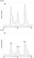
- FIG.6Aillustrates the heated water consumption rate on a typical day at a hotel having an occupancy rate of 70% in an exemplary profile 600: recorded peaks exist between 6 a.m. - 7 a.m. (90% - 100% users on-site), 12 p.m. - 1 p.m. (30% - 45% users on-site), and 7 p.m.- 8 p.m. (60 - 80% users on-site).
- An exemplary profile 601 in FIG.6Bdepicts the heated water consumption rate on an average day at a hotel with a 90% occupancy rate; wherein recorded data is available up to the concurrent time at 9:30 a.m.
- the typical historic records stored in memory means 111including but not limited to the archived profile 600, and the projected number of users at the hotel, are attributes to establishing profile 601.
- the first recorded peak 601-1exists between 6 a.m.- 7 a.m. (90 - 100% users on-site).
- application server 110projects the total number of users at the hotel at any time, by subtracting each departed tracked user with respect to the recorded departure time, and adding an arriving tracked user with respect to the projected arrival time at the hotel, in addition to an estimated number of residing untracked users.
- the typical per user consumption rate of heated water at peak demandis 45 liter/hour, whereas a typical daily per user consumption of heated water at 60 - 160 liters.
- the projection on heated water consumption ratemay be segregated into 9:30 a.m.- 1:30 p.m. with a prime accuracy within 4 hours from concurrent time, and at a secondary accuracy from 1:30 p.m.- 12 a.m.
- the projected peak 601-2 at 12 p.m.- 1 p.m. and projected peak 601-3 at 7 p.m.- 9 p.m.are shown in profile 601, which is continually amended with most recently recorded and calculated lead time period ⁇ t a pertinent to each tracked user.
- application server 110calculates the required volume of heated water in a storage tank type water heater at setpoint temperature, typically between 48 ° C to 60 ° C, which is readily for use. Energy conservation may be achieved by consistently maintaining a minimal 30 liter per user of heated water volume, or V, at setpoint temperature.
- Application server 110continually projects the total number of users n, for establishment of a database pertaining to profile 601. At step 540 of FIG.5 , application server 110 transports the related information to one or more separate systems, which includes at least one of control station 120 , and water heater system of environmental attribute means 130 .
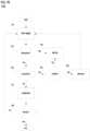
- table 700is an exemplary dynamic schedule indicating priority in providing housekeeping services in a five storey hotel. This schedule can be displayed via a communicatively connected device, including but not limited to mobile device 103, and thin client 113 ( FIG.1 )
- Slot 701shows the clocktime used by the tracking system.
- Slot 702indicates different states of a rented room.
- Application server 110receives a message from a separate, communicatively connected system indicating the status of each hotel room as 'not rented', 'unoccupied', etc.
- the lead time period ⁇ t a of a user pertaining to a rented room at center-of-mass 201is determined on the basis of a single geo-fence boundary 204 with geo-fenced area 203 pertaining to 20 minute traffic time.
- the lead time period ⁇ t a relating to the time period before the user returns to center-of-mass 201is determined at '20 minutes', given the tracked user location is within the geo-fenced area.
- the lead time period ⁇ t ais suggested at '20 minutes+' otherwise.
- Application server 110changes the lead time period ⁇ t a related to each unoccupied rented room in table 700 in accordance with the periodically updated proximity log of the corresponding tracked user.
- the housekeeping staffcan prioritize the unoccupied rented rooms to be serviced; and change the room status through said communicatively connected device as 'room cleaned', upon completion of the housekeeping task.
- the tracking system of the inventionhouse watches a monitored space in accordance with the continually updated attributes, as well as, proximity logs of one or more mobile devices 103 carried by the related tracked users.
- the tracking systemdetermines the security status, and the operative modes of a plurality of devices 140 within or related to a monitored house, in accordance with an exemplary process 750 in FIG.7B .
- application server 110determines whether one or more mobile devices 103 are within or outside the pertinent monitored house, in accordance with the corresponding proximity logs. At step 751 of process 750, application server 110 periodically receives signal transmissions, including but not limited to data comprising the occupancy attribute from occupancy attribute means 150 pertaining to the monitored house , as well as, said one or more mobile devices 103.
- application server 110analyzes the signal transmissions.
- signal transmissionsare disrupted or discontinued - application server 110 sends a probe signal to control station 120 via network 102, and the response is in-compliant with preconfigured parameters.
- application server 110sends an alert to a third party, comprising at least one of the property management, security organization, mobile device 103, and thin client 113.
- signal transmissions incompliance between control station 120 and application server 110are not experienced, process 750 proceeds to step 754. Wherein, application server 110 analyzes said occupancy attribute.
- application server 110determines that the house is 'occupied', or, application server 110 receives a message comprising change in said occupancy of the house; wherein, such change comprises a few aspects.
- device 140comprising a door lock detects a visiting party's attempt to switch the locked state to unlocked state, and sends a corresponding signal to application server 110.
- step 755application server 110 analyzes the proximity logs of said one or more mobile devices 103. If application server 110 fails to verify the identities of occupants in the occupied house, or, the identity of said visiting party attempting to switch the locked state to the unlocked state of a door lock pertinent to the unoccupied house, an alert is sent to said third party in accordance with step 753. In a different embodiment, the identities of occupants are verified, alternatively, the identity of said visiting party is verified. In a further embodiment, application server 110 determines in accordance with the proximity logs, one or more mobile device 103 are approaching the house within a close proximity threshold. Process 750 proceeds to step 756.
- application server 110distinguishes said verified occupants, or verified said visiting party, or verified said approaching one or more mobile device 103, by analyzing the identifiers and the corresponding proximity logs. In accordance with the results of identity distinguishment, application server 110 sends one or more signals for receipt by said plurality of devices 140 to change the operative mode from an 'unattended state' to a 'user configuredstate', or, from an 'unattended state' to a 'management state'.
- application server 110receives the audit trail from a door lock pertaining to device 140, records in memory means 111 ( FIG.1 ) and sends to said third party time-in and time-out of all entries and exits, in accordance with the results of identity verification and distinguishment.
- application server 110determines that the monitored house is 'unoccupied'. At step 757, application server 110 sends to control station 120, one or more signals for receipt by a plurality of devices 140, to change the operative mode to an 'unattended state'. Process 750 proceeds to step 758.
- application server 110determines if there is change, including but not limited to the pertinence between said one or more mobile devices 103, and said monitored house. In one embodiment, application server 110 determines no said change - process 750 returns to step 751. In an alternative embodiment, application server 110 determines said change. In one exemplary aspect, the pertinence between said one or more mobile devices 103 and said house - being a lease - is discontinued upon check-out. Process 750 is ended.
- the inventionrelates to a tracking system that governs control of indoor climate and water supply reserve, operative modes of selected devices and sending of projected arrival time of related users of a monitored space.
- One aspect of the inventionrelates to energy optimization in a rented hotel room and a house, and to activate on-demand device operation.
- a schedule with dynamic data pertaining to projected time of user arriving at said monitored spaceenabling planning of provision of services and allocation of human resources.
- the systemenables security of said monitored space by generating and sending an alert upon detection of unidentified occupancy. And, the system enables communicatively connected devices to trigger alert while being opened/closed by unidentified user.
- External Devicecommunicatively connected to the system, including but not limited to a door lock, a light fixture, a home appliance, a safe, etc.
- Thin Client -a network linked electronic device with computing capacity, such as a microcomputer or a handheld personal digital assistant (,PDA'), etc.
- a network linked electronic device with computing capacitysuch as a microcomputer or a handheld personal digital assistant (,PDA'), etc.
- Operative Mode -a device with power connection operating at an unspecified level.
- Management Statean operative mode of a device operating at configurations imposed by property management, including but not limited to reduced power consumption.
- Unattended Statean operative mode of a device operating at different levels, comprising: reduced power consumption, including but not limited to 'sleep' mode and 'standby' mode; alternatively, a device is configured to set off an alarm if the physical state is changed, including but not limited to 'locked' to 'unlocked', 'closed' to 'open'; and, code/PIN entry for attempt of open or use.
- User Configured Statean operative mode of a device performing at one or more user specified levels, selected from functions, security level, or power consumption.
Landscapes
- Engineering & Computer Science (AREA)
- Business, Economics & Management (AREA)
- Physics & Mathematics (AREA)
- General Physics & Mathematics (AREA)
- Tourism & Hospitality (AREA)
- Automation & Control Theory (AREA)
- Theoretical Computer Science (AREA)
- Human Resources & Organizations (AREA)
- General Business, Economics & Management (AREA)
- Strategic Management (AREA)
- Economics (AREA)
- Marketing (AREA)
- Computer Networks & Wireless Communication (AREA)
- Operations Research (AREA)
- Signal Processing (AREA)
- Entrepreneurship & Innovation (AREA)
- Quality & Reliability (AREA)
- General Engineering & Computer Science (AREA)
- Primary Health Care (AREA)
- Health & Medical Sciences (AREA)
- Radar, Positioning & Navigation (AREA)
- General Health & Medical Sciences (AREA)
- Remote Sensing (AREA)
- Chemical & Material Sciences (AREA)
- Aviation & Aerospace Engineering (AREA)
- Combustion & Propulsion (AREA)
- Mechanical Engineering (AREA)
- Telephonic Communication Services (AREA)
- Selective Calling Equipment (AREA)
- Alarm Systems (AREA)
- Mobile Radio Communication Systems (AREA)
- Air Conditioning Control Device (AREA)
- Navigation (AREA)
- Traffic Control Systems (AREA)
- Audible And Visible Signals (AREA)
- Management, Administration, Business Operations System, And Electronic Commerce (AREA)
Description
- The present invention relates to a user location tracking system ('tracking system') and methods to locate user carried mobile devices, such as those used in digital cellular systems, personal communications systems ('PCS'), enhanced specialized mobile radios ('ESMRs'), radio frequency (`RF') based tracking systems (Bluetooth, WiFi), and other wireless communications systems. More particularly, but not exclusively, the present disclosure relates to methods that employ the location of the individually tracked user to determine the time at which the user arrives (`arrival time') at a monitored space, including the corresponding rented room at a hotel (`rented room'), and the total number of tracked users at a monitored space for control of the related conditions.
- A residing guest ('user') at a hotel contributes to energy consumption in the use of a rented room through two primary utility sources: Heating, Ventilating and Air - Conditioning system ('HVAC') and heated water. In conventional HVAC systems, the temperature within a rented room is raised or lowered at multiple operating levels. The indoor temperature is typically maintained at three different levels. The setpoint level is often selected by the user when the rented room is attended. The comfort level is maintained at a few degrees from the setpoint temperature for energy conservation when the rented room is unoccupied while allowing speedy resume to the setpoint level. The free level is used for maximal energy conservation of an unrented room. In furtherance, housekeeping services are preferably provided to the rented room during guest unattended moments. Other services such as control of devices and security pertaining to a monitored space are currently enacted with other automation systems.
WO 2011/149600 A2 relates to a computer-implemented system for controlling an energy management system dependent on the location of mobile devices of users. In particular, a thermostat is used for controlling a HVAC device.WO 2011/121299 A1 relates to a HVAC control system of a building which takes into account the planned use of a building dependent on the user's current location and the estimated time of arrival of the user at the building.US 2011/231020 A1 discloses a control system which determines an adjustment for altering an operating temperature setting for a site based on the distance between the mobile device and the site.- A common problem of the comfort level of a monitored space is often that the setback temperature is either too far away from the setpoint temperature to provide satisfactory comfort when someone returns to the rented room, or too close to the setpoint temperature to achieve adequate energy savings. Indoor temperature at comfort level requires a drive time to be resumed to setpoint temperature; the corresponding estimated minimal required drive time is therefore overly inaccurate. The `Short Cycling' phenomenon may result from insufficient operating times, leading to overshooting the user's setpoint temperature and unbounded up/down temperature cycles within a given time period. The result is unavoidable damage to the HVAC system and shortening of the general operative life span.
- Heated water at setpoint temperature must also be readily supplied to the monitored space. Water heaters fall into one of two categories: 1. tankless type water heaters, and 2. storage tank type water heaters. Consumption of heated water greatly varies within different times of the day and during different seasons of the year notwithstanding, the volume is also dependent on the number of users being onsite. Should the heated water supply be planned on basis of the projected number of users being at the monitored space during the day, the volume of heated water allocated on the per user basis can be maintained at an interrelated level.
- In addition, the devices within a monitored space are not restricted for use of intended users. Home appliances are largely automated through programmed configurations and distant control, but are unable to respond in accordance with user identification.
- The present invention provides an apparatus as defined in the appended
claim 1 and a method as defined in the appended claim 14. The apparatus and method may be used to determine the user's arrival time at an unoccupied monitored space for determination of the setback temperature or the quantity of heated water consumption. Scheduling of service provisions is also discussed herein. The operative modes of devices related to the monitored space may be changed in accordance with detected or expected presence of intended users. - The setback temperature of the unoccupied monitored space can be drifted to the farthest level from the user configured setpoint level, and is driven to the setpoint level in accordance with the system determined arrival times of one or more users. The quantity of readily supplied heated water is drifted and driven in accordance with expected number of users remaining or arriving in the monitored space. Maximal energy savings can be achieved. In furtherance, change of operative modes of devices related to the rented room with restriction to intended users, not only enhances user experience, it also renders strengthened security.
- The method may comprise locating and recording with respect to time a proximity log related to location of a user carried mobile device encompassing one or more transmitters for wireless communication. In one embodiment, said mobile device is further equipped with location analysis functionality and selectively transmits a message encompassing the proximity log on its location relative to a predetermined geo-fence area. The system includes an application server that receives the message and may determine the user's arrival time at the rented room. In furtherance, the application server may proceed with the calculation of the total number of tracked users with respect to time during the day. The control station sends obtained attributes to the application server, and may control connected attribute station and external devices in accordance with received proximity logs sent from the application server. The control station may include but is not limited to a Building Management System, and a gateway with internet and WLAN connectivity.
- In one embodiment, the application server estimates the drive time of temperature response in a HVAC controlled room by the following steps: obtaining the indoor temperature at a beginning point, intermediate points and an end point of the prior drive operation; calculating a drive curve using the beginning, intermediate and end temperatures; and using the drive curve to estimate a time at which the desired temperature will be reached. In an alternative embodiment, estimating the drive time may comprise the steps of: obtaining a plurality of indoor temperature data samples over a period of time corresponding to the prior drive operation; calculating a plurality of drive curve sections, each section calculated using a subset of data samples; conjoining all calculated drive curve sections.
- In another embodiment, the quantity of heated water consumption during the day is calculated. The application server projects the daily peaks of actual water consumption by utilizing the consumption rate versus time on basis of historic operations, composing a curve of the daily consumption rate versus time, and using the projected number of users at the hotel on basis of a plurality of received proximity logs, and therefore the arrival times of tracked users, to project the time at which the daily peaks of heated water consumption will be reached.
- In a further embodiment of the method, the application server estimates the time duration of each rented room being in an unoccupied status and composes a schedule of housekeeping service in priority. The dynamic information is stored in a server connected memory means. Determining and setting the operative modes of selected devices related with the rented room may be performed on the basis of the concurrent user location and in accordance with preset operating parameters or user authorization.
- The drawings constitute to embodiments of the present invention and serve to depict the apparatuses infrastructure and operating principles.
FIG. 1 is a block diagram representation of the present invention of the tracking system.FIG.2A depicts a traveling trace of user carried mobile device with respect to a polygonal geo-fenced area.FIG.2B depicts the locations of user carried mobile device at different instantaneous times with respect to a circular geo-fenced area.FIG.3 is a graph depicting the calculated thermal drift & drive relationships within a monitored space, using a non-linear equation.FIG.4 is a graph depicting the thermal drift & drive relationships within a monitored space, identifying recorded data samples over a period of time.FIG.5 is a flow chart depicting a method to calculate setback room temperature settings, and the projected heated water consumption quantity, using the user location and projected user's arrival time at a hotel.FIG.6A is a graph depicting the historic heated water consumption rate on an average day at a hotel.FIG.6B is a graph depicting the recorded heated water consumption rate, and projected heated water consumption rate based on a plurality of projected users' arrival times at a hotel.FIG.7A depicts a schedule for allocating human resources in service provisions with prioritization in accordance with rented room users' arrival times.FIG.7B is a flow chart depicting a method to house watch a monitored space.- The present invention may be better understood with reference to embodiments depicted by supporting drawings, however, it is not intended that the invention be restricted to those depicted embodiments. Those skilled in the art will recognize that variations and modifications can be made without departing from the true scope of the invention as defined by the claims. It is therefore intended to include within the invention all such variations and modifications as fall within the scope of the appended claims and equivalents thereof.
FIG. 1 illustrates the present invention in environment100, in which certain preferences in geo-fence details, operating parameters and controls information are selectively sent fromapplication server 110 tomobile device 103.Mobile device 103 is enabled to transmit preferred messages toapplication server 110 for data logging.Application server 110 performs projection of the arrival time at the rented room of the user carryingmobile device 103. At any time, the user can send a m anually entered arrival time throughmobile device 103 toapplication server 110.- Geo-
location system 101 is a terrestrial or satellite based positioning system; some of which include but not limited to the Beidou Navigation System , Differential GPS (' DGPS'), Eurofix DGPS, Global Positioning System ('GPS'), pertaining to the Global Navigation Satellite System ('GNSS'). In other types of positioning systems, geo-location system 101 comprising cellular communication towers, or other systems provid ing reference points , transmit RF signals that are received bymobile device 103. Mobile device 103 encompasses embedded device104 (e.g. an onboard computer with memory means (not shown) and limited functionality ), geo-receiver 105,telematics device 106 and thecorresponding antennae device 104 is wirelessly loaded with operating parameters, which include but not limited to the geo-fence boundary definitions, the clock time, and the polling interval, etc.Mobile devices 103 include a cellular phone, and a handheld device possessing wireless communication connectivity, such as a tablet computer, and the like.- Typically , geo-
receiver 105 processes geo-location system 101 sent signals received byantenna 108, for obtainment of the current location ofmobile device 103. In one embodiment,mobile device 103 determines its location by engaging in the tri-lateration process.Telematics device 106 transmits toapplication server 110 via antenna107 - at constant or variable specific frequency in time as per the preconfigured polling interval - coded wireless messages comprising the present location and a unique identifier ofmobile device 103. In an alternative embodiment,mobile device 103 transmits toapplication server 110 bytelematics device 106 viaantenna 107 said coded wireless messages at a defined polling interval in accordance with receivedapplication server 110 sent periodic probe requests. Application server 110 receives information encompassing themobile device 103 location and unique identifier vianetwork 102. In an example not according to theinvention application server 110 executes a program which calculates the lead time period pertaining to the user's arrival time at the related rented room. In the presentinvention application server 110 assigns a predefined lead time period on the basis of the geo-fenced area - related to a geo-fence boundary - in whichmobile device 103 is located. The lead time period and the operating parameters ofmobile device 103 are changed in accordance with change in the mobile device103located geo-fenced area.Application server 110 may be any equipment capable of facilitating two way communications with telematics device106onmobile device 103. In another embodiment,mobile device 103 calculates the lead time period pertaining to the user's arrival time at the related rented room; it sends the most updated proximity log - encompassing at least the calculated lead time period and the unique identifier toapplication server 110 in said coded wireless messages.- A library of predefined geo-fence boundaries, the polling interval at constant or variable frequency directing data logging between
application server 110 andmobile device 103, quantitative calculations performed byapplication server 110 , and other information such as personal data of the user, is stored in memory means111 and retrieved byapplication server 110 via a wired or wireless communicative network. Memory means111, working with or withinapplication server 110 , can be any device, including magnetic, optical or solid-state memory ; where stored information can be changed via a communicatively connectedthin client 113. - In an outdoor environment for use with geo-
location system 101,network 102 uses a combination of wireless and landline communication infrastructure such as a cellular telecommunication system and the internet, provides two-way data logging betweentelematics device 106 andapplication server 110 . - On the other hand, the wireless and landline communication infrastructure of
network 102 pertinent to an indoor tracking system, as depicted inFIG.1 , typically encompasses a combination of WLAN/Ethernet. Wherein, user carriedmobile device 103 possessing Bluetooth communicative components and functionality is continually tracked through a node based mesh network (not shown) constructed on basis of a plurality ofBluetooth beacons 112. Bluetooth beacon112transmits a signal tomobile device 103 in the indoor environment, and transports the returning signal to the communicatively connectedapplication server 110. Operatively similar to said outdoor tracking system, the proximity log encompassing the lead time period pertaining to the user's arrival time at the related rented room is obtained byapplication server 110 on basis of the position ofmobile device 103 . - Referring to
FIG.2A , geo-fencedarea 203 is the area within a polygonal geo-fence boundary 204 . The geo-fencedarea 203 has a center-of-mass 20 1, and a computedcircular approximation 205 withradius 20 2 , corresponding to the maximum offset between the computed center-of-mass 201 and the furthest edge of geo-fence boundary 204. The dotted trace22 0 depict s an exemplary path ofmobile device 103 crossing geo-fence boundary 204 and traveling away from center-of-mass 201, being the related rented room at a hotel, as in one embodiment. - In
FIG.2A , a zone of Level 0 is defined as an area beyond circular approximation205 : a zone ofLevel 1 may be defined as the area withincircular approximation 205 .Application server 110 can alter the shape of geo-fence boundary 204 withinzone Level 1 , in accordance with preconditioning factor s pertinent to traffic conditions, time of the day, the unique identifier ofmobile device 103 and characteristics of the user or the related rented room, etc. - In one embodiment,
application server 110 correlates the data pertinent to the real-time location of the user carryingmobile device 103 to a preconfigured lead time period Δta , which is the time period between the current time and the projected user's arrival time at center-of-mass 201. A preconfigured value is assigned for lead time period Δta1 whenmobile device 103 is atposition 211, and within the geo-fencedarea 203 ; another preconfigured value is assigned for lead time period Δta2 whenmobile device 103 is atposition 212, which is outside geo-fence boundary 204. - Referring now to
FIG.2B , illustrated is geo-fencedarea 253 pertaining to circular geo-fence boundary 254 . G eo-fence boundary 254 havingradius 252 has been defined aroundcentral point 251 , being the rented room at the hotel, as in one embodiment . The dotted trace22 1 depicts an exemplary path ofmobile device 103 crossing ing geo-fence boundary 254 and traveling towardcentral point 251. A zone of Level 0 is defined as an area outside geo-fence boundary254: a zone ofLevel 1 i s the area within geo-fence boundary 254.Application server 110 can alter the coverage ofzone Level 1 within geo-fence boundary 254, in accordance with preconditioning factors pertinent to traffic conditions, time of the day, the unique identifier ofmobile device 103 and characteristics of the user or the related rented room, etc. - In an example not according to the invention,
application server 110 correlates the data pertinent to the real-time location ofmobile device 103 to a mathematical calculation of lead time period Δta, as follows:
where Δta is the lead time period between the current time and the projected user's arrival time at the rented room of central point25 1 ; γ represents a preconfigured factor pertinent to the uncertain preconditions affecting lead time period Δta , such as time of the day, the unique identifier ofmobile device 103 and characteristics of the user or the related rented room, etc .; d is the distance between the concurrent location of the monitoredmobile device 103 and central point25 1 ; v is the user's velocity of travel, which may be calculated, using:
where v, is periodically calculated on basis of the time difference to travel from one location to another. For instance, v is indicated by the difference between d1 (traversal distance betweenfirst position 261 and central point25 1), and d2 (traversal distance betweensecond position 262 and central point25 1 ), divided by the difference of t1 (instantaneous time recorded at first position261), and t2 (instantaneous time recorded at second position262). O ther formulae and methods may seem fit in different situations where appropriate and therefore can also be applied for calculation of lead time period Δta .Application server 110 performs the calculations and sends the calculated values of lead time period Δta to controlstation 120 and other systems. - Those skilled in the art will appreciate that the exemplary methods disclosed herein may be applied to any geo-fenced area represented by any number of shapes and sizes. A geo-fence around a center of mass may range in complexity from a line to a highly irregular shape which more accurately follows the landscape of the hotel premises and neighborhood. There are a number of methods for constructing these geo-fences which will be apparent to one skilled in the art.
- Thermal Drift & Drive Relationships
FIG .3 illustrates an exemplary temperature change in an indoor space, wherein the outdoor temperature is lower than indoor setpoint temperature Tset of the space. Ambient temperature Tamb is the temperature at which indoor temperature T (t) will theoretically reach in accordance with indefinite increase in time t, when the HVAC heating operation is off; it is at a constant level in this case for demonstration purposes.- Drift curve300 -1 represents the 'drift process' of indoor temperature T(t) with respect to time, beginning at a rapid rate decreasing from setpoint temperature Tset as indoor temperature T(t) approaches the steady-state temperature, which is substantially the same as ambient temperature Tamb . Drive curve300 -2 represents the 'drive process' of i ndoor temperature T(t) of the space being driven from ambient temperature Tamb up to setpoint temperature Tset in relation to time during a HVAC heating operation. The drive rate is decreasing as i ndoor temperature T(t) approaches setpoint temperature Tset T he required time period to drift indoor temperature T(t) from one level to another varies in accordance with time and season, as well as other factors such as the weather and energy sinks within the space. In contrast, drive curve300-2 is dependent on the unique space environment, and HVAC system performance. The data pertaining to the relationships between temperature responses to HVAC operation must be obtained to project the time period for indoor temperature T (t) to drift from one point to another, as well as the time to drive indoor temperature T (t) from one point to another. For a cooled room on a warm day, the principles are the same, yet the direction s of increasing temperature on the y-axis would be inverted.
- In one embodiment, mathematical functions may be used to describe the temperature responses through drift curve300 -1 and drive curve300 -2 . In an exemplary use case, Newton's Law of Cooling is used for calculation of the drift and drive performances. The rate of change of indoor temperature T(t) over time dT/dt , is proportional to the difference between indoor temperature T(t) and ambient temperatur e Tamb . A differential equation is used in a mathematical form, as follows:

where indoor temperature T(t) corresponds to a drift process from setpoint temperature Tset to ambient temperature Tamb. Solving the differential equation,
we yield an equation having indoor temperature T(t) as a function of time :
where k is a constant dependent on the surrounding environment within the space. Having measured indoor temperature T(t) at any time t, and knowing ambient temperature Tamb , the value of k can be easily sorted . - In an alternative embodiment,
application server 110 obtains ambient temperature Tamb , indoor temperature T(t) pertaining to the drift and drive data from environmental attribute means130, records, and stores the data in memory means111. In yet another embodiment,application server 110 receives a data feed fromcontrol station 120 , or other external sources, comprising drift and drive data of indoor temperature T (t), and ambient temperature Tamb. Calculations, data recording and external information source pertaining to obtainment of drift data, drive data and ambient temperature Tamb, can be continually processed, stored in memory means111, and used for studying indoor temperature T(t) responses versus time t during a HVAC cooling or heating operation in a space. FIG .4 illustrates an exemplary indoor temperature T(t) response in accordance withdrift curve 4 00 -1 and drivecurve 4 00 -2. Dotted curve400 -3 of the fluctuating ambient temperature Tamb varies in compliance with outdoor temperature changes during the day.- Setback temperature Tsb is a temperature level of an unoccupied rented room maintained by a HVAC system, which is intended to resume to setpoint temperature Tset within a short time after user entry. The required time to drive setback temperature Tsb to setpoint temperature Tset is recovery time period Δtr - which is dependent on the HVAC system capacity. It is better expressed as :

where tset is the time at which indoor temperature T(t) is driven toward setpoint temperature Tset; tsb is the starting time of the drive process, at which indoor temperature T(t) equals to setback temperature Tsb. - In one embodiment,
application server 110 calculates recovery time period Δtr on the basis of the obtained user's arrival lead time period Δta , then extrapolates the corresponding indoor setback temperature Tsb , based on the relationships between the temperature responses and time in a drift process and a drive process. Attention is drawn with care to make sure that recovery time period Δtr should be within lead time period Δta to complete drive of setback temperature Tsb to setpoint temperature Tset:
Or,
where α represents a preconfigured factor mathematically describing the uncertainty affecting lead time period Δta . In another embodiment, recovery time period Δtr is also expressed as:
where recovery rater (expressed in unit time per unit temperature, such as seconds per°C) is the rate for the HVAC system to drive i ndoor temperature toward setpoint temperature Tset . Recovery rater is calculated as follows:
where T(t) is the indoor temperature of the space during any time t. - Data encompassing recovery rater in relation with a mbient temperature Tamb can be stored in memory means111 . Any technique of calculating and combining the most recently calculated recovery rate r and a n archived recovery rater can also be utilized
- Other than recovery rater yielded by equation [8] or others, the manufacturer of the HVAC system also provides the recommended recover raterm under different ambient conditions for assurance of optimal operative efficacies and equipment life span. Therefore, recovery rater should be maintained at a rate not exceeding the recommended recover raterm:

Or,
whereB represents a preconfigured factor mathematically describing variables affecting recovery rate r in a temperature drive operation . Substituting equations [6] and [9] into equation [7] :
setback indoor temperature Tsb of a space using lead time period Δta , is yielded. - These drift and drive parameters are used in the methods of the invention for determining the corresponding setback temperature Tsb , as shown in flow chart500 of
FIG .5 . Typically,application server 110 determines the values of setback temperature Tsb in the unoccupied rented room, while receiving different location related information pertaining tomobile device 103. It is realized thatapplication server 110 receives information encompassing whether the rented room status is unoccupied, from a separate system. - At
step 510,application server 110 periodically receives data pertaining to the rented room fromcontrol station 120, including setpoint temperature Tset , indoor temperature T(t) and ambient temperature Tamb , and stores the data in memory means111 for mathematical establishment of thermal drift & drive relationships as illustrated in an exemplary graphical form inFIG.4 . It is worthwhile to point out that the objective conditions - such as ambient temperature Tamb - are continuously changing; said thermal drift & drive relationships are on a continually updated mathematical platform that affects the calculated results. - In one embodiment, a user carrying
mobile device 103 departs from the rented room. Atstep 520,application server 110 receives the proximity log frommobile device 103 carried by the user of the rented room - said information including but not limited to indicating the operative environment for trackingmobile device 103 being outdoor or indoor based. At the same time,application server 110 determines if the rented room is unoccupied on basis of information received from at least one other communicatively connected system.Application server 110 analyzes the proximity log and ends the process if the rented room status is identified as 'checked-out'. Conversely,application server 110 projects the time at which the user will return to the rented room and determines a corresponding setback indoor temperature Tsb , on basis of archived numerical thermal drift and drive data. The process proceeds to step530. - Referring to
FIG.2B ,application server 110 receives the proximity log frommobile device 103 corresponding to thefirst position 261 recorded at the first instantaneous time t1, and determines the value of d1 (traversal distance betweenfirst position 261 and central point251). Atstep 530, application server110 - in one embodiment - uses a preconfigured value of lead time period Δta1 on basis ofposition 261 being outside geo-fencedarea 253, and calculates the corresponding recovery time period Δtr1 , using equation [6].Application server 110 extrapolates the corresponding setback indoor temperature Tsb1, based on the temperature responses in a drift process and drive process of the rented room as shown inFIG.4 . Alternatively,application server 110 calculates setback temperature Tsb1 by using equation [10]. Atstep 540,application server 110 sends data pertaining to setback temperature Tsb1 to controlstation 120, for controlling HVAC system of environmental attribute means130 in maintaining temperature of the rented room at a less energy demanding setback temperature Tsb1. The process returns to step510. - In an example not according to the present invention,
application server 110 receives the proximity log frommobile device 103 corresponding to thesecond position 262 recorded at the second instantaneous time t2, and determines the value of d2 (traversal distance betweensecond position 262 and central point25 1). Atstep 530,application server 110 calculates the user's velocity of travel v, using equation [2]:
substituting velocity v into equation [1] to yield lead time period Δta2 ,application server 110 calculates the corresponding recovery time period Δtr2 , using equation [6]. Application server 110 extrapolates the corresponding setback indoor temperature Tsb2 , based on the temperature responses in a drift process and drive process of the rented room as shown inFIG.4 . Alternatively,application server 110 calculates setback temperature Tsb2 by using equation [10]. Atstep 540 ,application server 110 sends data pertaining to setback temperature Tsb2 to controlstation 120.Control station 120 initiates HVAC system of environmental attribute means130 for adjusting indoor temperature T (t) from s etback temperature Tsb1 to setback temperature Tsb2 . Setback temperature Tsb2 will be driven to setpoint temperature Tset within recovery time period Δtr2.- In another aspect of the invention, the tracking system is applied to projection of the total number of tracked users at the hotel with respect to time. Having obtained each tracked user's time of departing, and time of arriving at the hotel in accordance with the user's proximity log, yields the estimated number of total users at the hotel during any time of the day. In furtherance, the settings of the temperature and the reserve volume in the hotel water heater system of environmental attribute means130 can be projected.
- The hotel's daily heated water consumption pattern is a function of the number of users and time, whereas, controls in heated water supply apply to the water flow, as well as, the heat flow.
FIG.6A illustrates the heated water consumption rate on a typical day at a hotel having an occupancy rate of 70% in an exemplary profile600: recorded peaks exist between 6 a.m. - 7 a.m. (90% - 100% users on-site), 12 p.m. - 1 p.m. (30% - 45% users on-site), and 7 p.m.- 8 p.m. (60 - 80% users on-site). - An
exemplary profile 601 inFIG.6B depicts the heated water consumption rate on an average day at a hotel with a 90% occupancy rate; wherein recorded data is available up to the concurrent time at 9:30 a.m. The typical historic records stored in memory means111 (FIG.1 ) including but not limited to thearchived profile 600, and the projected number of users at the hotel, are attributes to establishingprofile 601. The first recorded peak601-1 exists between 6 a.m.- 7 a.m. (90 - 100% users on-site). - In one embodiment,
application server 110 projects the total number of users at the hotel at any time, by subtracting each departed tracked user with respect to the recorded departure time, and adding an arriving tracked user with respect to the projected arrival time at the hotel, in addition to an estimated number of residing untracked users. The typical per user consumption rate of heated water at peak demand is 45 liter/hour, whereas a typical daily per user consumption of heated water at 60 - 160 liters. The projection on heated water consumption rate may be segregated into 9:30 a.m.- 1:30 p.m. with a prime accuracy within 4 hours from concurrent time, and at a secondary accuracy from 1:30 p.m.- 12 a.m. The projected peak601-2 at 12 p.m.- 1 p.m. and projected peak601-3 at 7 p.m.- 9 p.m. are shown inprofile 601, which is continually amended with most recently recorded and calculated lead time period Δta pertinent to each tracked user. - In yet another embodiment,
application server 110 calculates the required volume of heated water in a storage tank type water heater at setpoint temperature, typically between 48°C to 60°C, which is readily for use. Energy conservation may be achieved by consistently maintaining a minimal 30 liter per user of heated water volume, or V, at setpoint temperature. The total required heated water volume in storage at any time, Vtot, can be found:
where n is total number of users at the hotel. - The heated water consumption Δ V within a time period Δt can be sought, using the following equation:

where Q is the per user flow rate of heated water use. Application server 110 continually projects the total number of users n, for establishment of a database pertaining toprofile 601. Atstep 540 ofFIG.5 ,application server 110 transports the related information to one or more separate systems, which includes at least one ofcontrol station 120 , and water heater system of environmental attribute means130 .- The tracking system of the invention also applies to human resources allocation in hotelier operations. Referring to
FIG.7A , table 700 is an exemplary dynamic schedule indicating priority in providing housekeeping services in a five storey hotel. This schedule can be displayed via a communicatively connected device, including but not limited tomobile device 103, and thin client113 (FIG.1 ) - Slot701shows the clocktime used by the tracking system.
Slot 702 indicates different states of a rented room. Application server110receives a message from a separate, communicatively connected system indicating the status of each hotel room as 'not rented', 'unoccupied', etc. Referring toFIG.2A , the lead time period Δta of a user pertaining to a rented room at center-of-mass 201 is determined on the basis of a single geo-fence boundary 204 with geo-fencedarea 203 pertaining to 20 minute traffic time. The lead time period Δta relating to the time period before the user returns to center-of-mass 201 is determined at '20 minutes', given the tracked user location is within the geo-fenced area. The lead time period Δta is suggested at '20 minutes+' otherwise. Application server110changes the lead time period Δta related to each unoccupied rented room in table700 in accordance with the periodically updated proximity log of the corresponding tracked user. The housekeeping staff can prioritize the unoccupied rented rooms to be serviced; and change the room status through said communicatively connected device as 'room cleaned', upon completion of the housekeeping task. - The tracking system of the invention house watches a monitored space in accordance with the continually updated attributes, as well as, proximity logs of one or more
mobile devices 103 carried by the related tracked users. In one aspect, the tracking system determines the security status, and the operative modes of a plurality ofdevices 140 within or related to a monitored house, in accordance with an exemplary process750 inFIG.7B . - Referring to
FIG. 1 ,application server 110 determines whether one or moremobile devices 103 are within or outside the pertinent monitored house, in accordance with the corresponding proximity logs. Atstep 751 of process750,application server 110 periodically receives signal transmissions, including but not limited to data comprising the occupancy attribute from occupancy attribute means150 pertaining to the monitored house , as well as, said one or moremobile devices 103. - At
step 752,application server 110 analyzes the signal transmissions. In one embodiment, signal transmissions are disrupted or discontinued -application server 110 sends a probe signal to controlstation 120 vianetwork 102, and the response is in-compliant with preconfigured parameters. Atstep 753,application server 110 sends an alert to a third party, comprising at least one of the property management, security organization,mobile device 103, andthin client 113. In a contrary embodiment, signal transmissions incompliance betweencontrol station 120 andapplication server 110 are not experienced, process750 proceeds to step754. Wherein,application server 110 analyzes said occupancy attribute. - In one embodiment,
application server 110 determines that the house is 'occupied', or,application server 110 receives a message comprising change in said occupancy of the house; wherein, such change comprises a few aspects. In one exemplary aspect,device 140 comprising a door lock detects a visiting party's attempt to switch the locked state to unlocked state, and sends a corresponding signal toapplication server 110. - At
step 755,application server 110 analyzes the proximity logs of said one or moremobile devices 103. Ifapplication server 110 fails to verify the identities of occupants in the occupied house, or, the identity of said visiting party attempting to switch the locked state to the unlocked state of a door lock pertinent to the unoccupied house, an alert is sent to said third party in accordance withstep 753. In a different embodiment, the identities of occupants are verified, alternatively, the identity of said visiting party is verified. In a further embodiment,application server 110 determines in accordance with the proximity logs, one or moremobile device 103 are approaching the house within a close proximity threshold. Process750 proceeds to step756. - At
step 756,application server 110 distinguishes said verified occupants, or verified said visiting party, or verified said approaching one or moremobile device 103, by analyzing the identifiers and the corresponding proximity logs. In accordance with the results of identity distinguishment, application server110sends one or more signals for receipt by said plurality ofdevices 140 to change the operative mode from an 'unattended state' to a 'user configuredstate', or, from an 'unattended state' to a 'management state'. In one embodiment,application server 110 receives the audit trail from a door lock pertaining todevice 140, records in memory means111 (FIG.1 ) and sends to said third party time-in and time-out of all entries and exits, in accordance with the results of identity verification and distinguishment. - In an alternative embodiment, application server110determines that the monitored house is 'unoccupied'. At
step 757, application server110sends to controlstation 120, one or more signals for receipt by a plurality ofdevices 140, to change the operative mode to an 'unattended state'. Process750 proceeds to step758. - At
step 758,application server 110 determines if there is change, including but not limited to the pertinence between said one or moremobile devices 103, and said monitored house. In one embodiment,application server 110 determines no said change - process 750 returns to step 751. In an alternative embodiment,application server 110 determines said change. In one exemplary aspect, the pertinence between said one or moremobile devices 103 and said house - being a lease - is discontinued upon check-out. Process 750 is ended. - While the present invention has been described herein in detail in relation to one or more preferred embodiments, it is to be understood that this disclosure is only illustrative and exemplary of the present invention and is made merely for the purpose of providing a full and enabling disclosure of the invention. The foregoing disclosure is not intended to be construed to limit the present invention or otherwise exclude any such other embodiments, adaptations, variations, modifications or equivalent arrangements, the present invention being limited only by the claims appended hereto and the equivalents thereof.
- The invention relates to a tracking system that governs control of indoor climate and water supply reserve, operative modes of selected devices and sending of projected arrival time of related users of a monitored space.
- One aspect of the invention relates to energy optimization in a rented hotel room and a house, and to activate on-demand device operation.
- In a further aspect, a schedule with dynamic data pertaining to projected time of user arriving at said monitored space enabling planning of provision of services and allocation of human resources.
- In yet another aspect, the system enables security of said monitored space by generating and sending an alert upon detection of unidentified occupancy. And, the system enables communicatively connected devices to trigger alert while being opened/closed by unidentified user.
- External Device - communicatively connected to the system, including but not limited to a door lock, a light fixture, a home appliance, a safe, etc.
- Thin Client - a network linked electronic device with computing capacity, such as a microcomputer or a handheld personal digital assistant (,PDA'), etc.
- Off Mode - power disconnection.
- Operative Mode - a device with power connection operating at an unspecified level.
- Management State - an operative mode of a device operating at configurations imposed by property management, including but not limited to reduced power consumption.
- Unattended State - an operative mode of a device operating at different levels, comprising: reduced power consumption, including but not limited to 'sleep' mode and 'standby' mode; alternatively, a device is configured to set off an alarm if the physical state is changed, including but not limited to 'locked' to 'unlocked', 'closed' to 'open'; and, code/PIN entry for attempt of open or use.
- User Configured State - an operative mode of a device performing at one or more user specified levels, selected from functions, security level, or power consumption.


Claims (14)
- Apparatus for controlling an environmental attribute of a monitored space according to the geographic location of a mobile device in relation to said monitored space, comprising:an application server having computing capability, which processes information received via a network, from a communicatively connected control station controlling an environmental attribute means, and which receives a geographic location or a proximity log pertaining to said present geographic location from said mobile device;a control station for monitoring the level of an environmental attribute of said monitored space and sending a detected level of said environmental attribute to said application server, and for driving said environmental attribute of said monitored space through controlling said environmental attribute means, andthe mobile device adapted to send its present geographic location, or a proximity log pertaining to its present geographic location, to said application server,in which said application server, or said control station, establishes and records a drive relationship in a communicatively connected memory, which describes the change of said environmental attribute pertaining to said monitored space with respect to time for being driven to a set point from an ambient level or from a farthest level relative to said set point, said set point representing a predetermined level of said environmental attribute in said monitored space, and,in which said application server, or said control station, establishes and records a drift relationship in a communicatively connected memory, which describes the change of said environmental attribute in said monitored space with respect to time when drifting from said set point toward an ambient level or toward said farthest level relative to said set point,in which said application server determines a setback point of said environmental attribute in accordance with said established drive relationship and drift relationship, by calculating a time of arrival of said mobile device at said monitored space on the basis of a present geographic location of said mobile device, wherein the present geographic location is sent to said application server from said mobile device, or is calculated on the basis of a proximity log sent to said application server from said mobile device,in which said setback point is determined by said application server, or said control station, such that a setback recovery time period representing a length of time said environmental attribute in said monitored space takes to be driven from said setback point to said set point by said control station, through controlling said environmental attribute means in accordance with said established drive relationship, is equal to or less than a lead time period, between the present time and a calculated time of arrival of said mobile device at said monitored space,in which said control station allows said environmental attribute in said monitored space to drift to said setback point, and drives said environmental attribute so it reaches said set point at said calculated time of arrival, andin which said application server assigns the lead time period for said mobile device to arrive at said monitored space as one preconfigured value when said present geographic location of said mobile device is within a geofence area comprising said monitored space within thereof, and assigns the lead time period for said mobile device to arrive at said monitored space as another preconfigured value when said present geographic location of said mobile device is outside of said geofence area.
- The apparatus of claim 1, in which said present geographic location is sent to said application server from said mobile device, for determination of said lead time period by said application server.
- The apparatus of claim 1, wherein said proximity log sent to said application server from said mobile device, comprises said lead time period between the present time and the projected arrival time of the user carrying said mobile device.
- The apparatus of claim 1, in which said application server is adapted to alter the geofence area in accordance with preconditioning factors pertinent to selected traffic conditions, time, as well as, characteristics of users and user carried mobile device pertaining to said monitored space.
- The apparatus of any preceding claim, in which said monitored space is a guest room in a hotel, a house, or an office unit in a commercial building.
- The apparatus of any preceding claim, in which said environmental attribute of said monitored space is indoor temperature, and in which said environmental attribute means comprises a temperature sensor, and at least one of a heating unit, an air conditioning unit and a ventilating unit.
- The apparatus of any one of claims 1 to 5, in which said environmental attribute of said monitored space is humidity, and in which said environmental attribute means comprises a humidity sensor, and at least one of a humidifier and a dehumidifier.
- The apparatus of any preceding claims, further comprising an occupancy attribute means adapted to indicate whether the monitored space is occupied, and wherein said control station allows said environmental attribute to drift to said setback point when said occupancy attribute means indicates the monitored space is unoccupied.
- The apparatus of any preceding claims, in which said application server receives a signal from a device comprising a door lock, which is communicatively linked with said application server, in case a visiting party of the monitored space attempts to switch the locked state to unlocked state or determines in accordance with the proximity logs, whether one or more mobile devices are approaching the monitored space within a close proximity threshold.
- The apparatus of any one of claims 1 to 5, in which said environmental attribute of said monitored space is a heated water reserve quantity at a predetermined temperature in a storage tank and in which said environmental attribute means comprises a sensor for measuring said heated water reserve quantity in said storage tank and a water heating unit, whereas optionally the drift relationship and the drive relationship describe the consumption and replenishment, respectively, of water reserve quantity in the storage tank.
- The apparatus of any claims 1 to 5, in which said environmental attribute of said monitored space is a temperature of heated water reserve in a storage tank and in which said environmental attribute means comprises a sensor for measuring said heated water temperature in said storage tank and a water heating unit.
- The apparatus of any preceding claim, in which said network comprises an indoor and outdoor tracking system used by said mobile device to determine its present geographic location, in which said application server is a network connected server, including at least one of a network connected device with computing capability, and an internet connected cloud-based server.
- Use of the apparatus of any one of the preceding claims to control an environmental attribute of a monitored space.
- A method of controlling an environmental attribute of a monitored space according to the geographic location of a mobile device in relation to said monitored space, comprising:monitoring the level of an environmental attribute of said monitored space using an environmental attribute means, andsending a detected level of said environmental attribute to an application server via the network,sending a present geographic location of said mobile device to said application server via the network,establishing and recording a drive relationship which describes the change of said environmental attribute pertaining to said monitored space with respect to time for being driven to a set point from an ambient level or from a farthest level relative to said set point,establishing and recording a drift relationship which describes the change of said environmental attribute in said monitored space with respect to time when drifting from said set point toward an ambient level or toward said farthest level relative to said set point,determining a setback point of said environmental attribute in accordance with said established drive relationship and drift relationship, by calculating a time of arrival of said mobile device at said monitored space on the basis of a present geographic location or proximity log of said mobile device, wherein said setback point is determined such that a setback recovery time period representing a length of time that said environmental attribute in said monitored space takes to be driven from said setback point to said set point in accordance with said established drive relationship, is equal to or less than a lead time period, between the present time and said calculated time of arrival of said mobile device at said monitored space,allowing said environmental attribute in said monitored space to drift to said setback point, and driving said environmental attribute so it reaches said set point at said calculated time of arrival,in which said application server assigns the lead time period for said mobile device to arrive at said monitored space as one preconfigured value when said present geographic location of said mobile device is within a geofence area comprising said monitored space within thereof, and assigns the lead time period for said mobile device to arrive at said monitored space as another preconfigured value when said present geographic location of said mobile device is outside of said geofence area.
Priority Applications (1)
| Application Number | Priority Date | Filing Date | Title |
|---|---|---|---|
| EP21151235.5AEP3828787A1 (en) | 2012-05-17 | 2013-05-17 | Information control system |
Applications Claiming Priority (2)
| Application Number | Priority Date | Filing Date | Title |
|---|---|---|---|
| US201261648115P | 2012-05-17 | 2012-05-17 | |
| PCT/CN2013/075845WO2013170791A1 (en) | 2012-05-17 | 2013-05-17 | Information control system |
Related Child Applications (2)
| Application Number | Title | Priority Date | Filing Date |
|---|---|---|---|
| EP21151235.5ADivision-IntoEP3828787A1 (en) | 2012-05-17 | 2013-05-17 | Information control system |
| EP21151235.5ADivisionEP3828787A1 (en) | 2012-05-17 | 2013-05-17 | Information control system |
Publications (3)
| Publication Number | Publication Date |
|---|---|
| EP2850501A1 EP2850501A1 (en) | 2015-03-25 |
| EP2850501A4 EP2850501A4 (en) | 2016-01-20 |
| EP2850501B1true EP2850501B1 (en) | 2023-03-29 |
Family
ID=49583161
Family Applications (2)
| Application Number | Title | Priority Date | Filing Date |
|---|---|---|---|
| EP21151235.5APendingEP3828787A1 (en) | 2012-05-17 | 2013-05-17 | Information control system |
| EP13790120.3AActiveEP2850501B1 (en) | 2012-05-17 | 2013-05-17 | Information control system |
Family Applications Before (1)
| Application Number | Title | Priority Date | Filing Date |
|---|---|---|---|
| EP21151235.5APendingEP3828787A1 (en) | 2012-05-17 | 2013-05-17 | Information control system |
Country Status (10)
| Country | Link |
|---|---|
| US (3) | US9323255B2 (en) |
| EP (2) | EP3828787A1 (en) |
| JP (3) | JP6259817B2 (en) |
| KR (1) | KR20150020171A (en) |
| CN (2) | CN104321711B (en) |
| AU (5) | AU2013262189B2 (en) |
| CA (1) | CA2866291C (en) |
| GB (3) | GB2517853B (en) |
| SG (1) | SG11201407331XA (en) |
| WO (1) | WO2013170791A1 (en) |
Families Citing this family (47)
| Publication number | Priority date | Publication date | Assignee | Title |
|---|---|---|---|---|
| US8862280B1 (en)* | 2011-06-13 | 2014-10-14 | Gridpoint, Inc. | Dynamic load curtailment system and method |
| US9115908B2 (en)* | 2011-07-27 | 2015-08-25 | Honeywell International Inc. | Systems and methods for managing a programmable thermostat |
| CN104285106B (en)* | 2012-05-14 | 2018-06-05 | 三菱电机株式会社 | Air conditioning units and air conditioning systems |
| KR20150020171A (en)* | 2012-05-17 | 2015-02-25 | 찬, 훈 맨 레나 | Information control system |
| US20150163945A1 (en) | 2013-12-11 | 2015-06-11 | Honeywell International Inc. | Hvac controller with thermistor biased against an outer housing |
| JP2017513152A (en)* | 2014-02-10 | 2017-05-25 | イウン、スツ・ファンIUN, Sut Fan | Life system |
| EP3237811B1 (en)* | 2014-12-22 | 2021-01-27 | Trane International Inc. | Occupancy sensing and building control using mobile devices |
| WO2016140842A1 (en)* | 2015-03-02 | 2016-09-09 | George Josman C | Temperature control device |
| US9900174B2 (en) | 2015-03-06 | 2018-02-20 | Honeywell International Inc. | Multi-user geofencing for building automation |
| US9967391B2 (en) | 2015-03-25 | 2018-05-08 | Honeywell International Inc. | Geo-fencing in a building automation system |
| US9609478B2 (en) | 2015-04-27 | 2017-03-28 | Honeywell International Inc. | Geo-fencing with diagnostic feature |
| US10802459B2 (en) | 2015-04-27 | 2020-10-13 | Ademco Inc. | Geo-fencing with advanced intelligent recovery |
| US10802469B2 (en) | 2015-04-27 | 2020-10-13 | Ademco Inc. | Geo-fencing with diagnostic feature |
| US10430710B2 (en)* | 2015-10-23 | 2019-10-01 | Accenture Global Services Limited | Connected hotels guest experience |
| US10057110B2 (en) | 2015-11-06 | 2018-08-21 | Honeywell International Inc. | Site management system with dynamic site threat level based on geo-location data |
| US10516965B2 (en) | 2015-11-11 | 2019-12-24 | Ademco Inc. | HVAC control using geofencing |
| US9628951B1 (en) | 2015-11-11 | 2017-04-18 | Honeywell International Inc. | Methods and systems for performing geofencing with reduced power consumption |
| US9860697B2 (en) | 2015-12-09 | 2018-01-02 | Honeywell International Inc. | Methods and systems for automatic adjustment of a geofence size |
| US9560482B1 (en) | 2015-12-09 | 2017-01-31 | Honeywell International Inc. | User or automated selection of enhanced geo-fencing |
| US10605472B2 (en) | 2016-02-19 | 2020-03-31 | Ademco Inc. | Multiple adaptive geo-fences for a building |
| CN105872468B (en)* | 2016-04-20 | 2019-01-22 | 张满仓 | a monitoring method |
| CN105928143B (en) | 2016-04-28 | 2019-03-15 | 京东方科技集团股份有限公司 | Movement and control method, monitoring node and system of air humidifying device |
| US10999793B2 (en)* | 2016-07-18 | 2021-05-04 | Netgear, Inc. | Power management techniques for a power sensitive wireless device |
| US11184851B2 (en) | 2016-07-18 | 2021-11-23 | Netgear, Inc. | Power management techniques for a power sensitive wireless device |
| US10302322B2 (en) | 2016-07-22 | 2019-05-28 | Ademco Inc. | Triage of initial schedule setup for an HVAC controller |
| US10488062B2 (en) | 2016-07-22 | 2019-11-26 | Ademco Inc. | Geofence plus schedule for a building controller |
| US10306403B2 (en) | 2016-08-03 | 2019-05-28 | Honeywell International Inc. | Location based dynamic geo-fencing system for security |
| US11506422B2 (en)* | 2016-11-29 | 2022-11-22 | Rheem Australia Pty Limited | Location based temperature limit control for a water heater |
| US10558722B2 (en) | 2017-03-31 | 2020-02-11 | Intel Corporation | Provision of on premise ambient service method and apparatus |
| US10317102B2 (en) | 2017-04-18 | 2019-06-11 | Ademco Inc. | Geofencing for thermostatic control |
| JP7155508B2 (en)* | 2017-10-26 | 2022-10-19 | 富士フイルムビジネスイノベーション株式会社 | Equipment, management system and program |
| US20190156589A1 (en)* | 2017-11-22 | 2019-05-23 | Bank Of America Corporation | System for communicable integration of an automobile system and a toll system |
| CN108088054A (en)* | 2017-12-15 | 2018-05-29 | 广东五月花网络科技有限公司 | A kind of air conditioner |
| US10990109B2 (en) | 2018-05-22 | 2021-04-27 | Bank Of America Corporation | Integrated connectivity of devices for resource transmission |
| DE112019006670T5 (en)* | 2019-01-17 | 2021-11-04 | Mitsubishi Electric Corporation | Air conditioning control system |
| KR102809926B1 (en) | 2019-04-11 | 2025-05-22 | 삼성전자주식회사 | Home applicance and control method for the same |
| JP2021005267A (en)* | 2019-06-27 | 2021-01-14 | ソニー株式会社 | Information processing device, information processing method, and program |
| EP3988851A4 (en)* | 2019-06-30 | 2022-08-17 | GD Midea Air-Conditioning Equipment Co., Ltd. | CONTROL METHOD OF AIR CONDITIONER, AIR CONDITIONER, SERVER AND STORAGE HOLDER |
| IT201900013962A1 (en)* | 2019-08-05 | 2021-02-05 | De Longhi Appliances Srl | CONDITIONING APPARATUS AND REGULATION METHOD |
| WO2021033307A1 (en)* | 2019-08-22 | 2021-02-25 | 株式会社大正スカイビル | Rental space |
| CN111010224B (en)* | 2019-12-26 | 2021-02-02 | 中国科学院国家空间科学中心 | An S-band satellite communication terminal for maritime mobile platforms |
| US11402113B2 (en)* | 2020-08-04 | 2022-08-02 | Honeywell International Inc. | Methods and systems for evaluating energy conservation and guest satisfaction in hotels |
| WO2022168045A1 (en)* | 2021-02-07 | 2022-08-11 | Octopus Energy Group Limited | Methods and systems for predictively preparing water provision system |
| GB202101678D0 (en)* | 2021-02-07 | 2021-03-24 | Octopus Energy Ltd | Methods and systems and apparatus to support reduced energy and water usage |
| AU2022217537B2 (en)* | 2021-02-07 | 2024-05-16 | Octopus Energy Heating Limited | Methods and systems for predictively preparing water provision system |
| CN114063675B (en)* | 2021-11-12 | 2022-07-19 | 维沃移动通信有限公司 | Temperature control method and device |
| CN115930380B (en)* | 2022-12-06 | 2024-11-15 | 青岛海尔空调器有限总公司 | Air conditioner control method, device and air conditioner |
Citations (2)
| Publication number | Priority date | Publication date | Assignee | Title |
|---|---|---|---|---|
| US20110153525A1 (en)* | 2009-12-18 | 2011-06-23 | Alcatel-Lucent Usa Inc. | Method and system for managing power consumption using geolocation information |
| EP2348371A1 (en)* | 2010-01-22 | 2011-07-27 | Assa Abloy Hospitality, Inc. | Energy management and security in multi-unit facilities |
Family Cites Families (41)
| Publication number | Priority date | Publication date | Assignee | Title |
|---|---|---|---|---|
| US5395042A (en)* | 1994-02-17 | 1995-03-07 | Smart Systems International | Apparatus and method for automatic climate control |
| US5915473A (en)* | 1997-01-29 | 1999-06-29 | American Standard Inc. | Integrated humidity and temperature controller |
| JP2001231083A (en)* | 2000-02-17 | 2001-08-24 | Mitsubishi Electric Corp | Automatic equipment control system |
| US6748343B2 (en)* | 2000-09-28 | 2004-06-08 | Vigilos, Inc. | Method and process for configuring a premises for monitoring |
| JP3522686B2 (en)* | 2000-12-13 | 2004-04-26 | 松下電器産業株式会社 | Mobile terminal, automatic remote control system and automatic remote control method |
| US7669777B2 (en)* | 2001-05-07 | 2010-03-02 | Automated Logic Corporation | Slope predictive control and digital PID control for a variable temperature control system |
| US8082096B2 (en)* | 2001-05-22 | 2011-12-20 | Tracbeam Llc | Wireless location routing applications and architecture therefor |
| KR20030041690A (en)* | 2001-11-21 | 2003-05-27 | 엘지전자 주식회사 | Home automation control apparatus and method using global positioning system |
| US7216016B2 (en) | 2004-01-20 | 2007-05-08 | Carrier Corporation | Failure mode for HVAC system |
| US7178350B2 (en)* | 2004-01-20 | 2007-02-20 | Carrier Corporation | Determination of maximum allowable humidity in indoor space to avoid condensation inside building envelope |
| CN101072629B (en)* | 2004-01-20 | 2010-05-05 | 开利公司 | Single integrated humidity/ventilation control in hvac systems |
| CN100501720C (en)* | 2004-01-20 | 2009-06-17 | 开利公司 | Failure Modes of Heating, Ventilation and Air Conditioning Systems |
| US7385499B2 (en)* | 2004-12-17 | 2008-06-10 | United Parcel Service Of America, Inc. | Item-based monitoring systems and methods |
| JP2006284477A (en)* | 2005-04-04 | 2006-10-19 | Denso Corp | Navigation system for vehicle, and remote control operation system for equipment in residence |
| US20070114295A1 (en)* | 2005-11-22 | 2007-05-24 | Robertshaw Controls Company | Wireless thermostat |
| US7493211B2 (en) | 2005-12-16 | 2009-02-17 | General Electric Company | System and method for updating geo-fencing information on mobile devices |
| JP4872360B2 (en)* | 2006-01-23 | 2012-02-08 | パナソニック電工株式会社 | Remote control system |
| US8086352B1 (en)* | 2007-10-04 | 2011-12-27 | Scott Elliott | Predictive efficient residential energy controls |
| JP2009017564A (en)* | 2008-07-10 | 2009-01-22 | Zenrin Co Ltd | Control of network devices using location information of mobile objects and use of mobile terminals |
| US8125332B2 (en) | 2008-11-21 | 2012-02-28 | Zoombak, Inc. | Geo-fence with minimal false alarms |
| JP2010181461A (en)* | 2009-02-03 | 2010-08-19 | Olympus Corp | Digital photograph frame, information processing system, program, and information storage medium |
| JP2010213100A (en)* | 2009-03-11 | 2010-09-24 | Sony Ericsson Mobile Communications Ab | Communication terminal, device control method, and device control server |
| US8141791B2 (en)* | 2009-03-26 | 2012-03-27 | Howard Rosen | Energy management improvement for a heating system with reduced setpoint temperature during no occupancy based upon historical sampling of room thermal response with highest power heat applied |
| US8442752B2 (en)* | 2009-04-23 | 2013-05-14 | Ford Global Technologies, Llc | Climate control head with fuel economy indicator |
| US8350697B2 (en)* | 2009-05-18 | 2013-01-08 | Alarm.Com Incorporated | Remote device control and energy monitoring by analyzing data and applying rules |
| US8509954B2 (en)* | 2009-08-21 | 2013-08-13 | Allure Energy, Inc. | Energy management system and method |
| US8428550B2 (en)* | 2009-07-30 | 2013-04-23 | Extenet Systems Inc. | Real-time location determination for in-building distributed antenna systems |
| US9838255B2 (en)* | 2009-08-21 | 2017-12-05 | Samsung Electronics Co., Ltd. | Mobile demand response energy management system with proximity control |
| US8437772B2 (en)* | 2009-09-15 | 2013-05-07 | Qualcomm Incorporated | Transmitter position integrity checking |
| US8412381B2 (en)* | 2010-03-24 | 2013-04-02 | Mitsubishi Electric Research Laboratories, Inc. | HVAC control system |
| GB201005320D0 (en)* | 2010-03-30 | 2010-05-12 | Telepure Ltd | Improvements in controllers, particularly controllers for use in heating, ventilation and air conditioning systems |
| US8556188B2 (en)* | 2010-05-26 | 2013-10-15 | Ecofactor, Inc. | System and method for using a mobile electronic device to optimize an energy management system |
| US20120031984A1 (en)* | 2010-08-03 | 2012-02-09 | Massachusetts Institute Of Technology | Personalized Building Comfort Control |
| US20120085831A1 (en)* | 2010-10-07 | 2012-04-12 | Energy Eye, Inc. | Systems and methods for controlling the temperature of a room based on occupancy |
| US8718826B2 (en) | 2011-06-01 | 2014-05-06 | Emerson Electric Co. | System for remote control of a condition at a site |
| US8755943B2 (en)* | 2011-09-30 | 2014-06-17 | Johnson Controls Technology Company | Systems and methods for controlling energy use in a building management system using energy budgets |
| US8843238B2 (en)* | 2011-09-30 | 2014-09-23 | Johnson Controls Technology Company | Systems and methods for controlling energy use in a building management system using energy budgets |
| US9103558B2 (en)* | 2011-12-21 | 2015-08-11 | Lennox Industries Inc. | Method for detecting physical presence of a specific individual to control HVAC settings |
| KR20150020171A (en)* | 2012-05-17 | 2015-02-25 | 찬, 훈 맨 레나 | Information control system |
| DE102012014562A1 (en) | 2012-07-23 | 2014-01-23 | tado GmbH | Method and device for geopositioning-based control of delaying systems |
| CA2885867C (en) | 2012-09-30 | 2021-09-21 | Mark STEFANSKI | Preconditioning controls and methods for an environmental control system |
- 2013
- 2013-05-17KRKR1020147031870Apatent/KR20150020171A/ennot_activeCeased
- 2013-05-17JPJP2015511923Apatent/JP6259817B2/ennot_activeExpired - Fee Related
- 2013-05-17GBGB1419520.0Apatent/GB2517853B/ennot_activeExpired - Fee Related
- 2013-05-17CNCN201380025773.9Apatent/CN104321711B/enactiveActive
- 2013-05-17SGSG11201407331XApatent/SG11201407331XA/enunknown
- 2013-05-17AUAU2013262189Apatent/AU2013262189B2/enactiveActive
- 2013-05-17CACA2866291Apatent/CA2866291C/enactiveActive
- 2013-05-17GBGB1621299.5Apatent/GB2543439B/enactiveActive
- 2013-05-17EPEP21151235.5Apatent/EP3828787A1/enactivePending
- 2013-05-17CNCN201710963668.XApatent/CN107766951A/enactivePending
- 2013-05-17WOPCT/CN2013/075845patent/WO2013170791A1/enactiveApplication Filing
- 2013-05-17USUS13/896,600patent/US9323255B2/enactiveActive
- 2013-05-17GBGB1621465.2Apatent/GB2543440B/enactiveActive
- 2013-05-17EPEP13790120.3Apatent/EP2850501B1/enactiveActive
- 2016
- 2016-03-21USUS15/076,169patent/US10095250B2/enactiveActive
- 2016-08-24AUAU2016219597Apatent/AU2016219597A1/ennot_activeAbandoned
- 2017
- 2017-10-23JPJP2017204456Apatent/JP6700232B2/ennot_activeExpired - Fee Related
- 2018
- 2018-09-14USUS16/131,051patent/US20190011939A1/ennot_activeAbandoned
- 2019
- 2019-01-15AUAU2019200248Apatent/AU2019200248A1/ennot_activeAbandoned
- 2020
- 2020-01-31JPJP2020015139Apatent/JP2020074621A/enactivePending
- 2020-08-10AUAU2020217327Apatent/AU2020217327A1/ennot_activeAbandoned
- 2021
- 2021-09-30AUAU2021240265Apatent/AU2021240265A1/ennot_activeAbandoned
Patent Citations (2)
| Publication number | Priority date | Publication date | Assignee | Title |
|---|---|---|---|---|
| US20110153525A1 (en)* | 2009-12-18 | 2011-06-23 | Alcatel-Lucent Usa Inc. | Method and system for managing power consumption using geolocation information |
| EP2348371A1 (en)* | 2010-01-22 | 2011-07-27 | Assa Abloy Hospitality, Inc. | Energy management and security in multi-unit facilities |
Also Published As
Similar Documents
| Publication | Publication Date | Title |
|---|---|---|
| EP2850501B1 (en) | Information control system | |
| US10775067B2 (en) | Method for controlling activation of air conditioning device and apparatus therefor | |
| EP3169088B1 (en) | Methods and systems for performing geofencing with reduced power consumption | |
| US20190158305A1 (en) | Technologies for optimally individualized building automation | |
| US9618227B2 (en) | Energy management based on location | |
| JP6900100B2 (en) | Temperature control method and equipment | |
| EP2790082B1 (en) | A system and method with geo location triggering automatic action | |
| ES2872351T3 (en) | Automatic adjustment controls based on out-of-room presence information | |
| JP2019508654A (en) | Electronic device and control method thereof | |
| CN104048384B (en) | Energy management based on location | |
| CN107076444A (en) | Combined Air Conditioning System | |
| HK1233340A1 (en) | Information control system | |
| HK1233341A1 (en) | Information control system | |
| HK1206825B (en) | Information control system | |
| CN109780676A (en) | A kind of comfort of air conditioner control method of multi-mode |
Legal Events
| Date | Code | Title | Description |
|---|---|---|---|
| PUAI | Public reference made under article 153(3) epc to a published international application that has entered the european phase | Free format text:ORIGINAL CODE: 0009012 | |
| 17P | Request for examination filed | Effective date:20141216 | |
| AK | Designated contracting states | Kind code of ref document:A1 Designated state(s):AL AT BE BG CH CY CZ DE DK EE ES FI FR GB GR HR HU IE IS IT LI LT LU LV MC MK MT NL NO PL PT RO RS SE SI SK SM TR | |
| AX | Request for extension of the european patent | Extension state:BA ME | |
| RAX | Requested extension states of the european patent have changed | Extension state:BA Payment date:20141217 | |
| RA4 | Supplementary search report drawn up and despatched (corrected) | Effective date:20151217 | |
| RIC1 | Information provided on ipc code assigned before grant | Ipc:G05D 23/19 20060101ALI20151211BHEP Ipc:G06Q 10/00 20120101AFI20151211BHEP | |
| STAA | Information on the status of an ep patent application or granted ep patent | Free format text:STATUS: EXAMINATION IS IN PROGRESS | |
| 17Q | First examination report despatched | Effective date:20170112 | |
| RBV | Designated contracting states (corrected) | Designated state(s):AL AT BE BG CH CY CZ DE DK EE ES FI FR GR HR HU IE IS IT LI LT LU LV MC MK MT NL NO PL PT RO RS SE SI SK SM TR | |
| APBK | Appeal reference recorded | Free format text:ORIGINAL CODE: EPIDOSNREFNE | |
| APBN | Date of receipt of notice of appeal recorded | Free format text:ORIGINAL CODE: EPIDOSNNOA2E | |
| APBR | Date of receipt of statement of grounds of appeal recorded | Free format text:ORIGINAL CODE: EPIDOSNNOA3E | |
| APAF | Appeal reference modified | Free format text:ORIGINAL CODE: EPIDOSCREFNE | |
| APBT | Appeal procedure closed | Free format text:ORIGINAL CODE: EPIDOSNNOA9E | |
| RIN1 | Information on inventor provided before grant (corrected) | Inventor name:CHAN, KIT MENG Inventor name:CHAN, MARK KIT JIUN | |
| RAP1 | Party data changed (applicant data changed or rights of an application transferred) | Owner name:CHAN, KIT MENG Owner name:CHAN, HUN MAN LENA | |
| GRAP | Despatch of communication of intention to grant a patent | Free format text:ORIGINAL CODE: EPIDOSNIGR1 | |
| STAA | Information on the status of an ep patent application or granted ep patent | Free format text:STATUS: GRANT OF PATENT IS INTENDED | |
| RIN1 | Information on inventor provided before grant (corrected) | Inventor name:CHAN, KIT MENG Inventor name:CHAN, MARK KIT JIUN | |
| INTG | Intention to grant announced | Effective date:20221019 | |
| GRAS | Grant fee paid | Free format text:ORIGINAL CODE: EPIDOSNIGR3 | |
| GRAA | (expected) grant | Free format text:ORIGINAL CODE: 0009210 | |
| STAA | Information on the status of an ep patent application or granted ep patent | Free format text:STATUS: THE PATENT HAS BEEN GRANTED | |
| AK | Designated contracting states | Kind code of ref document:B1 Designated state(s):AL AT BE BG CH CY CZ DE DK EE ES FI FR GR HR HU IE IS IT LI LT LU LV MC MK MT NL NO PL PT RO RS SE SI SK SM TR | |
| REG | Reference to a national code | Ref country code:CH Ref legal event code:EP | |
| REG | Reference to a national code | Ref country code:DE Ref legal event code:R096 Ref document number:602013083521 Country of ref document:DE | |
| REG | Reference to a national code | Ref country code:AT Ref legal event code:REF Ref document number:1557199 Country of ref document:AT Kind code of ref document:T Effective date:20230415 | |
| REG | Reference to a national code | Ref country code:IE Ref legal event code:FG4D | |
| REG | Reference to a national code | Ref country code:LT Ref legal event code:MG9D | |
| PG25 | Lapsed in a contracting state [announced via postgrant information from national office to epo] | Ref country code:RS Free format text:LAPSE BECAUSE OF FAILURE TO SUBMIT A TRANSLATION OF THE DESCRIPTION OR TO PAY THE FEE WITHIN THE PRESCRIBED TIME-LIMIT Effective date:20230329 Ref country code:NO Free format text:LAPSE BECAUSE OF FAILURE TO SUBMIT A TRANSLATION OF THE DESCRIPTION OR TO PAY THE FEE WITHIN THE PRESCRIBED TIME-LIMIT Effective date:20230629 Ref country code:LV Free format text:LAPSE BECAUSE OF FAILURE TO SUBMIT A TRANSLATION OF THE DESCRIPTION OR TO PAY THE FEE WITHIN THE PRESCRIBED TIME-LIMIT Effective date:20230329 Ref country code:LT Free format text:LAPSE BECAUSE OF FAILURE TO SUBMIT A TRANSLATION OF THE DESCRIPTION OR TO PAY THE FEE WITHIN THE PRESCRIBED TIME-LIMIT Effective date:20230329 Ref country code:HR Free format text:LAPSE BECAUSE OF FAILURE TO SUBMIT A TRANSLATION OF THE DESCRIPTION OR TO PAY THE FEE WITHIN THE PRESCRIBED TIME-LIMIT Effective date:20230329 | |
| REG | Reference to a national code | Ref country code:NL Ref legal event code:MP Effective date:20230329 | |
| REG | Reference to a national code | Ref country code:AT Ref legal event code:MK05 Ref document number:1557199 Country of ref document:AT Kind code of ref document:T Effective date:20230329 | |
| PG25 | Lapsed in a contracting state [announced via postgrant information from national office to epo] | Ref country code:SE Free format text:LAPSE BECAUSE OF FAILURE TO SUBMIT A TRANSLATION OF THE DESCRIPTION OR TO PAY THE FEE WITHIN THE PRESCRIBED TIME-LIMIT Effective date:20230329 Ref country code:NL Free format text:LAPSE BECAUSE OF FAILURE TO SUBMIT A TRANSLATION OF THE DESCRIPTION OR TO PAY THE FEE WITHIN THE PRESCRIBED TIME-LIMIT Effective date:20230329 Ref country code:GR Free format text:LAPSE BECAUSE OF FAILURE TO SUBMIT A TRANSLATION OF THE DESCRIPTION OR TO PAY THE FEE WITHIN THE PRESCRIBED TIME-LIMIT Effective date:20230630 Ref country code:FI Free format text:LAPSE BECAUSE OF FAILURE TO SUBMIT A TRANSLATION OF THE DESCRIPTION OR TO PAY THE FEE WITHIN THE PRESCRIBED TIME-LIMIT Effective date:20230329 | |
| PG25 | Lapsed in a contracting state [announced via postgrant information from national office to epo] | Ref country code:SM Free format text:LAPSE BECAUSE OF FAILURE TO SUBMIT A TRANSLATION OF THE DESCRIPTION OR TO PAY THE FEE WITHIN THE PRESCRIBED TIME-LIMIT Effective date:20230329 Ref country code:RO Free format text:LAPSE BECAUSE OF FAILURE TO SUBMIT A TRANSLATION OF THE DESCRIPTION OR TO PAY THE FEE WITHIN THE PRESCRIBED TIME-LIMIT Effective date:20230329 Ref country code:PT Free format text:LAPSE BECAUSE OF FAILURE TO SUBMIT A TRANSLATION OF THE DESCRIPTION OR TO PAY THE FEE WITHIN THE PRESCRIBED TIME-LIMIT Effective date:20230731 Ref country code:ES Free format text:LAPSE BECAUSE OF FAILURE TO SUBMIT A TRANSLATION OF THE DESCRIPTION OR TO PAY THE FEE WITHIN THE PRESCRIBED TIME-LIMIT Effective date:20230329 Ref country code:EE Free format text:LAPSE BECAUSE OF FAILURE TO SUBMIT A TRANSLATION OF THE DESCRIPTION OR TO PAY THE FEE WITHIN THE PRESCRIBED TIME-LIMIT Effective date:20230329 Ref country code:AT Free format text:LAPSE BECAUSE OF FAILURE TO SUBMIT A TRANSLATION OF THE DESCRIPTION OR TO PAY THE FEE WITHIN THE PRESCRIBED TIME-LIMIT Effective date:20230329 | |
| PG25 | Lapsed in a contracting state [announced via postgrant information from national office to epo] | Ref country code:SK Free format text:LAPSE BECAUSE OF FAILURE TO SUBMIT A TRANSLATION OF THE DESCRIPTION OR TO PAY THE FEE WITHIN THE PRESCRIBED TIME-LIMIT Effective date:20230329 Ref country code:PL Free format text:LAPSE BECAUSE OF FAILURE TO SUBMIT A TRANSLATION OF THE DESCRIPTION OR TO PAY THE FEE WITHIN THE PRESCRIBED TIME-LIMIT Effective date:20230329 Ref country code:IS Free format text:LAPSE BECAUSE OF FAILURE TO SUBMIT A TRANSLATION OF THE DESCRIPTION OR TO PAY THE FEE WITHIN THE PRESCRIBED TIME-LIMIT Effective date:20230729 | |
| REG | Reference to a national code | Ref country code:CH Ref legal event code:PL | |
| REG | Reference to a national code | Ref country code:DE Ref legal event code:R097 Ref document number:602013083521 Country of ref document:DE | |
| PG25 | Lapsed in a contracting state [announced via postgrant information from national office to epo] | Ref country code:MC Free format text:LAPSE BECAUSE OF FAILURE TO SUBMIT A TRANSLATION OF THE DESCRIPTION OR TO PAY THE FEE WITHIN THE PRESCRIBED TIME-LIMIT Effective date:20230329 | |
| REG | Reference to a national code | Ref country code:BE Ref legal event code:MM Effective date:20230531 | |
| PG25 | Lapsed in a contracting state [announced via postgrant information from national office to epo] | Ref country code:MC Free format text:LAPSE BECAUSE OF FAILURE TO SUBMIT A TRANSLATION OF THE DESCRIPTION OR TO PAY THE FEE WITHIN THE PRESCRIBED TIME-LIMIT Effective date:20230329 Ref country code:LU Free format text:LAPSE BECAUSE OF NON-PAYMENT OF DUE FEES Effective date:20230517 Ref country code:LI Free format text:LAPSE BECAUSE OF NON-PAYMENT OF DUE FEES Effective date:20230531 Ref country code:DK Free format text:LAPSE BECAUSE OF FAILURE TO SUBMIT A TRANSLATION OF THE DESCRIPTION OR TO PAY THE FEE WITHIN THE PRESCRIBED TIME-LIMIT Effective date:20230329 Ref country code:CZ Free format text:LAPSE BECAUSE OF FAILURE TO SUBMIT A TRANSLATION OF THE DESCRIPTION OR TO PAY THE FEE WITHIN THE PRESCRIBED TIME-LIMIT Effective date:20230329 Ref country code:CH Free format text:LAPSE BECAUSE OF NON-PAYMENT OF DUE FEES Effective date:20230531 | |
| PLBE | No opposition filed within time limit | Free format text:ORIGINAL CODE: 0009261 | |
| STAA | Information on the status of an ep patent application or granted ep patent | Free format text:STATUS: NO OPPOSITION FILED WITHIN TIME LIMIT | |
| REG | Reference to a national code | Ref country code:IE Ref legal event code:MM4A | |
| 26N | No opposition filed | Effective date:20240103 | |
| PG25 | Lapsed in a contracting state [announced via postgrant information from national office to epo] | Ref country code:IE Free format text:LAPSE BECAUSE OF NON-PAYMENT OF DUE FEES Effective date:20230517 | |
| PG25 | Lapsed in a contracting state [announced via postgrant information from national office to epo] | Ref country code:IE Free format text:LAPSE BECAUSE OF NON-PAYMENT OF DUE FEES Effective date:20230517 | |
| PG25 | Lapsed in a contracting state [announced via postgrant information from national office to epo] | Ref country code:SI Free format text:LAPSE BECAUSE OF FAILURE TO SUBMIT A TRANSLATION OF THE DESCRIPTION OR TO PAY THE FEE WITHIN THE PRESCRIBED TIME-LIMIT Effective date:20230329 | |
| PG25 | Lapsed in a contracting state [announced via postgrant information from national office to epo] | Ref country code:SI Free format text:LAPSE BECAUSE OF FAILURE TO SUBMIT A TRANSLATION OF THE DESCRIPTION OR TO PAY THE FEE WITHIN THE PRESCRIBED TIME-LIMIT Effective date:20230329 Ref country code:IT Free format text:LAPSE BECAUSE OF FAILURE TO SUBMIT A TRANSLATION OF THE DESCRIPTION OR TO PAY THE FEE WITHIN THE PRESCRIBED TIME-LIMIT Effective date:20230329 Ref country code:BE Free format text:LAPSE BECAUSE OF NON-PAYMENT OF DUE FEES Effective date:20230531 | |
| PG25 | Lapsed in a contracting state [announced via postgrant information from national office to epo] | Ref country code:BG Free format text:LAPSE BECAUSE OF FAILURE TO SUBMIT A TRANSLATION OF THE DESCRIPTION OR TO PAY THE FEE WITHIN THE PRESCRIBED TIME-LIMIT Effective date:20230329 | |
| PG25 | Lapsed in a contracting state [announced via postgrant information from national office to epo] | Ref country code:BG Free format text:LAPSE BECAUSE OF FAILURE TO SUBMIT A TRANSLATION OF THE DESCRIPTION OR TO PAY THE FEE WITHIN THE PRESCRIBED TIME-LIMIT Effective date:20230329 | |
| PGFP | Annual fee paid to national office [announced via postgrant information from national office to epo] | Ref country code:DE Payment date:20250519 Year of fee payment:13 | |
| PGFP | Annual fee paid to national office [announced via postgrant information from national office to epo] | Ref country code:FR Payment date:20250521 Year of fee payment:13 | |
| PG25 | Lapsed in a contracting state [announced via postgrant information from national office to epo] | Ref country code:CY Free format text:LAPSE BECAUSE OF FAILURE TO SUBMIT A TRANSLATION OF THE DESCRIPTION OR TO PAY THE FEE WITHIN THE PRESCRIBED TIME-LIMIT; INVALID AB INITIO Effective date:20130517 | |
| PG25 | Lapsed in a contracting state [announced via postgrant information from national office to epo] | Ref country code:HU Free format text:LAPSE BECAUSE OF FAILURE TO SUBMIT A TRANSLATION OF THE DESCRIPTION OR TO PAY THE FEE WITHIN THE PRESCRIBED TIME-LIMIT; INVALID AB INITIO Effective date:20130517 |