EP2849660B1 - Atherectomy catheter drive assemblies - Google Patents
Atherectomy catheter drive assembliesDownload PDFInfo
- Publication number
- EP2849660B1 EP2849660B1EP13790133.6AEP13790133AEP2849660B1EP 2849660 B1EP2849660 B1EP 2849660B1EP 13790133 AEP13790133 AEP 13790133AEP 2849660 B1EP2849660 B1EP 2849660B1
- Authority
- EP
- European Patent Office
- Prior art keywords
- fiber
- drive assembly
- rotatable
- catheter
- fiber optic
- Prior art date
- Legal status (The legal status is an assumption and is not a legal conclusion. Google has not performed a legal analysis and makes no representation as to the accuracy of the status listed.)
- Active
Links
Images


Classifications
- A—HUMAN NECESSITIES
- A61—MEDICAL OR VETERINARY SCIENCE; HYGIENE
- A61B—DIAGNOSIS; SURGERY; IDENTIFICATION
- A61B1/00—Instruments for performing medical examinations of the interior of cavities or tubes of the body by visual or photographical inspection, e.g. endoscopes; Illuminating arrangements therefor
- A61B1/04—Instruments for performing medical examinations of the interior of cavities or tubes of the body by visual or photographical inspection, e.g. endoscopes; Illuminating arrangements therefor combined with photographic or television appliances
- A—HUMAN NECESSITIES
- A61—MEDICAL OR VETERINARY SCIENCE; HYGIENE
- A61B—DIAGNOSIS; SURGERY; IDENTIFICATION
- A61B1/00—Instruments for performing medical examinations of the interior of cavities or tubes of the body by visual or photographical inspection, e.g. endoscopes; Illuminating arrangements therefor
- A61B1/00064—Constructional details of the endoscope body
- A61B1/00066—Proximal part of endoscope body, e.g. handles
- A—HUMAN NECESSITIES
- A61—MEDICAL OR VETERINARY SCIENCE; HYGIENE
- A61B—DIAGNOSIS; SURGERY; IDENTIFICATION
- A61B1/00—Instruments for performing medical examinations of the interior of cavities or tubes of the body by visual or photographical inspection, e.g. endoscopes; Illuminating arrangements therefor
- A61B1/00112—Connection or coupling means
- A61B1/00121—Connectors, fasteners and adapters, e.g. on the endoscope handle
- A61B1/00126—Connectors, fasteners and adapters, e.g. on the endoscope handle optical, e.g. for light supply cables
- A—HUMAN NECESSITIES
- A61—MEDICAL OR VETERINARY SCIENCE; HYGIENE
- A61B—DIAGNOSIS; SURGERY; IDENTIFICATION
- A61B1/00—Instruments for performing medical examinations of the interior of cavities or tubes of the body by visual or photographical inspection, e.g. endoscopes; Illuminating arrangements therefor
- A61B1/00131—Accessories for endoscopes
- A61B1/00133—Drive units for endoscopic tools inserted through or with the endoscope
- A—HUMAN NECESSITIES
- A61—MEDICAL OR VETERINARY SCIENCE; HYGIENE
- A61B—DIAGNOSIS; SURGERY; IDENTIFICATION
- A61B1/00—Instruments for performing medical examinations of the interior of cavities or tubes of the body by visual or photographical inspection, e.g. endoscopes; Illuminating arrangements therefor
- A61B1/00147—Holding or positioning arrangements
- A61B1/0016—Holding or positioning arrangements using motor drive units
- A—HUMAN NECESSITIES
- A61—MEDICAL OR VETERINARY SCIENCE; HYGIENE
- A61B—DIAGNOSIS; SURGERY; IDENTIFICATION
- A61B1/00—Instruments for performing medical examinations of the interior of cavities or tubes of the body by visual or photographical inspection, e.g. endoscopes; Illuminating arrangements therefor
- A61B1/00163—Optical arrangements
- A61B1/00165—Optical arrangements with light-conductive means, e.g. fibre optics
- A—HUMAN NECESSITIES
- A61—MEDICAL OR VETERINARY SCIENCE; HYGIENE
- A61B—DIAGNOSIS; SURGERY; IDENTIFICATION
- A61B1/00—Instruments for performing medical examinations of the interior of cavities or tubes of the body by visual or photographical inspection, e.g. endoscopes; Illuminating arrangements therefor
- A61B1/06—Instruments for performing medical examinations of the interior of cavities or tubes of the body by visual or photographical inspection, e.g. endoscopes; Illuminating arrangements therefor with illuminating arrangements
- A61B1/07—Instruments for performing medical examinations of the interior of cavities or tubes of the body by visual or photographical inspection, e.g. endoscopes; Illuminating arrangements therefor with illuminating arrangements using light-conductive means, e.g. optical fibres
- A—HUMAN NECESSITIES
- A61—MEDICAL OR VETERINARY SCIENCE; HYGIENE
- A61B—DIAGNOSIS; SURGERY; IDENTIFICATION
- A61B1/00—Instruments for performing medical examinations of the interior of cavities or tubes of the body by visual or photographical inspection, e.g. endoscopes; Illuminating arrangements therefor
- A61B1/313—Instruments for performing medical examinations of the interior of cavities or tubes of the body by visual or photographical inspection, e.g. endoscopes; Illuminating arrangements therefor for introducing through surgical openings, e.g. laparoscopes
- A61B1/3137—Instruments for performing medical examinations of the interior of cavities or tubes of the body by visual or photographical inspection, e.g. endoscopes; Illuminating arrangements therefor for introducing through surgical openings, e.g. laparoscopes for examination of the interior of blood vessels
- A—HUMAN NECESSITIES
- A61—MEDICAL OR VETERINARY SCIENCE; HYGIENE
- A61B—DIAGNOSIS; SURGERY; IDENTIFICATION
- A61B17/00—Surgical instruments, devices or methods
- A61B17/32—Surgical cutting instruments
- A61B17/3205—Excision instruments
- A61B17/3207—Atherectomy devices working by cutting or abrading; Similar devices specially adapted for non-vascular obstructions
- A61B17/320758—Atherectomy devices working by cutting or abrading; Similar devices specially adapted for non-vascular obstructions with a rotating cutting instrument, e.g. motor driven
- A—HUMAN NECESSITIES
- A61—MEDICAL OR VETERINARY SCIENCE; HYGIENE
- A61B—DIAGNOSIS; SURGERY; IDENTIFICATION
- A61B5/00—Measuring for diagnostic purposes; Identification of persons
- A61B5/0059—Measuring for diagnostic purposes; Identification of persons using light, e.g. diagnosis by transillumination, diascopy, fluorescence
- A61B5/0062—Arrangements for scanning
- A61B5/0066—Optical coherence imaging
Definitions
- Atherectomyoffers a simple mechanical advantage over alternative therapies. By removing the majority of plaque mass (debulking), a larger initial lumen is created. As a result, stent deployment is greatly enhanced. Moreover, there are advantages to atherectomy related to the arterial healing response. When circumferential radial forces are applied to the vasculature, as in the case of angioplasty or stenting, the plaque mass is displaced, forcing the vessel wall to stretch dramatically. This stretch induces injury which is a known stimulus for the cellular in-growth that leads to restenosis.
- US 2006/093276discloses an optical system having a stationary optical fiber, a rotatable optical fiber, and a rotary junction comprising a pair of collimators that allows collimated light to be transmitted between the stationary optical fiber and the rotatable optical fiber.
- a drive assemblyas defined in the appended Claim 1. Described herein are drive assemblies for catheters having a rotatable cutter and on-board imaging.
- a drive assembly for driving an imaging catheterhas a rotatable fiber and a rotatable drive shaft.
- the drive assemblyincludes a fiber optic rotating junction having a stationary portion with a stationary fiber therein and a rotatable portion with a rotatable fiber therein.
- the drive assemblyincludes a first optical connection configured to connect the stationary fiber with a light source.
- the drive assemblyincludes a motor configured to rotate the rotatable portion of the fiber optic rotating junction.
- the drive assemblyincludes a second optical connection configured to connect the rotatable portion of the fiber optic rotating junction with both the drive shaft and the rotatable fiber of the imaging catheter so as to transmit torque from the motor to the drive shaft and the rotatable fiber of the catheter and so as to transmit light from the light source to the rotatable fiber of the catheter.
- the drive assemblyincludes a sensor configured to detect a rotational position of the fiber optic rotating junction.
- the drive assemblyoptionally includes a processor configured to obtain the detected rotational position and stop the motor only when the fiber optic rotating junction is in a predetermined rotational position.
- the sensorcan be a slot sensor configured to detect a flat on the rotary optical junction.
- the locking mechanismcan include mechanical features to physically align the handle with respect to the drive assembly.
- the locking mechanismcan be configured such that physical alignment of the catheter handle with respect to the drive assembly can further align an optical connection of the handle with the predetermined rotational position of the fiber optic rotating junction.
- the stationary and rotatable fiberscan be configured to transmit an optical coherence tomography signal.
- a method of driving an imaging catheter having a rotatable fiber and a rotatable drive shaftincludes connecting a stationary fiber of a stationary portion of a fiber optic rotating junction in a drive assembly with a light source; connecting a rotatable fiber of the fiber optic rotating junction with the drive shaft and the rotatable fiber of the imaging catheter; rotating the rotatable portion of a fiber optic rotating junction with a motor in the drive assembly such that both the drive shaft and the rotatable fiber of the imaging catheter rotate and such that light is transmitted from the light source to the rotatable fiber of the imaging catheter; sensing a position of the fiber optic rotating junction; and stopping the motor based upon the sensed position only when the fiber optic rotating junction is in a predetermined rotational position.
- Sensing the positioncan include sensing the position with a slot sensor.
- the methodcan include locking a handle of the imaging catheter into the drive assembly.
- the locking mechanismcan include mechanical features to physically align the catheter handle with respect to the drive assembly. Locking the handle of the imaging catheter into the drive assembly using the mechanical features can align an optical connection of the handle with the predetermined rotational position of the fiber optic rotating junction.
- the methodcan further include transmitting an optical coherence tomography signal through the stationary and rotatable fibers.
- a drive assembly for driving an imaging catheter having a rotatable fiber and a rotatable drive shaftincludes a drive assembly housing.
- the drive assemblyfurther includes a fiber optic rotating junction within the housing having a stationary portion with a stationary fiber therein and a rotatable portion with a rotatable fiber therein.
- the drive assemblyincludes a first optical connection through the housing configured to connect the stationary fiber with a light source.
- the drive assemblyincludes a motor within the housing configured to rotate the rotatable portion of the fiber optic rotating junction.
- the drive assemblyincludes a second optical connection through the housing configured to connect the rotatable portion of the fiber optic rotating junction with both the drive shaft and the rotatable fiber of the imaging catheter so as to transmit torque from the motor to the drive shaft and the rotatable fiber of the catheter and so as to transmit light from the light source to the rotatable fiber of the catheter.
- the housingis less than 1.23 litres (75 cubic inches) in volume, and the drive assembly has a total weight of less than 0.9 kg (2 pounds).
- the volumecan be less than 0.655 litres (40 cubic inches).
- the volumecan be less than 0.323 litres (20 cubic inches).
- the drive assemblycan further include a locking mechanism configured to lock a handle of the imaging catheter to the drive assembly.
- the stationary and rotatable fiberscan be configured to transmit an optical coherence tomography signal.
- a drive assembly for driving an imaging catheter having a rotatable fiber and a rotatable drive shaftincludes a fiber optic rotating junction having a stationary portion with a stationary fiber therein and a rotatable portion with a rotatable fiber therein.
- the drive assemblyincludes a first optical connection configured to connect the stationary fiber with a light source.
- the drive assemblyincludes a motor configured to rotate the rotatable portion of the fiber optic rotating junction.
- the motorhas a hollow shaft configured to house a portion of the fiber optic rotating junction such that the motor and the fiber optical rotating junction are coaxial.
- the drive assemblyincludes a second optical connection configured to connect the rotatable portion of the fiber optic rotating junction with both the drive shaft and the rotatable fiber of the imaging catheter so as to transmit torque from the motor to the drive shaft and the rotatable fiber of the catheter and so as to transmit light from the light source to the rotatable fiber of the catheter.
- the rotatable fiber of the fiber optic junctioncan be housed within the hollow shaft.
- the drive assemblycan further include a locking mechanism that can be configured to lock a handle of the imaging catheter to the drive assembly.
- the stationary and rotatable fiberscan be configured to transmit an optical coherence tomography signal.
- a drive assembly for driving an imaging catheter having a rotatable fiber and a rotatable drive shaftincludes a drive assembly housing.
- the drive assemblyfurther includes a fiber optic rotating junction within the housing having a stationary portion with a stationary fiber therein and a rotatable portion with a rotatable fiber therein.
- the drive assemblyincludes a first optical connection through the housing configured to connect the stationary fiber with a light source.
- the drive assemblyincludes a motor in the housing configured to rotate the rotatable portion of the fiber optic rotating junction.
- the drive assemblyincludes a linear slide in the housing configured to translate the fiber optic rotating junction axially within the housing.
- the drive assemblyincludes a second optical connection through the housing configured to connect the rotatable portion of the fiber optic rotating junction with both the drive shaft and the rotatable fiber of the imaging catheter so as to transmit torque from the motor to the drive shaft and the rotatable fiber and so as to transmit light from the light source to the rotatable fiber of the catheter.
- the stationary fiber of the fiber optic rotating junctioncan be axially fixed at the first optical connection.
- the stationary fiber of the fiber optic rotating junctioncan include slack configured to account for translation of the fiber optic rotating junction.
- the drive assemblycan further include a locking mechanism that can be configured to lock a handle of the imaging catheter to the drive assembly.
- the stationary and rotatable fiberscan be configured to transmit an optical coherence tomography signal.
- a drive assembly for driving an imaging catheter having a rotatable fiber and a rotatable drive shaftincludes a fiber optic rotating junction having a stationary portion with a stationary fiber therein and a rotatable portion with a rotatable fiber therein.
- the drive assemblyincludes a first optical connection configured to connect the stationary fiber with a light source.
- the drive assemblyincludes a motor configured to rotate the rotatable portion of the fiber optic rotating junction.
- the drive assemblyincludes a second optical connection configured to connect the rotatable portion of the fiber optic rotating junction with both the drive shaft and the rotatable fiber of the imaging catheter so as to transmit torque from the motor to the drive shaft and the rotatable fiber of the catheter and so as to transmit light from the light source to the rotatable fiber of the catheter.
- the drive assemblyincludes a magnetic locking mechanism configured to automatically align the second optical connection with the drive shaft and the rotatable fiber of the imaging catheter.
- the drive assembliescan include a motor to rotate both a drive shaft of the catheter and a rotating fiber of the catheter.
- the drive assemblies hereincan further include an optical pass-through to transfer light from a light source to the rotating fiber of the catheter, such as for optical coherence tomography (OCT) imaging.
- OCToptical coherence tomography
- the optical pass-throughcan include a fiber optic rotating junction having a stationary portion with a stationary fiber therein and a rotatable portion with a rotatable fiber therein.
- the drive assemblescan be configured to attach at the proximal end to a light source and at the distal end to a catheter.
- a drive assemblycan be configured to provide rotation of a drive shaft, simultaneous rotation of an optical fiber, translation of the drive shaft, and simultaneous translation of the fiber.
- Such drive assembliescould be used, for example, with a catheter having an imaging sensor and a cutter that are driven by the same drive shaft where the drive shaft can be translated proximally or distally to pack tissue and/or expose the cutter.
- a drive assembly 100can be configured to provide rotation of a drive shaft, rotation of an optical fiber, translation of the drive shaft, and translation of the fiber of an imaging catheter.
- the drive assembly 100can include a housing 101 (having an access door 107 therein) and a handle lock 103, to connect the drive assembly 100 to a
- the drive assembly 100can include a housing 101 (having an access door 107 therein) and a handle lock 103, to connect the drive assembly 100 to a catheter handle.
- the drive assembly 100can further include a rotary optical drive subassembly 102 configured to provide rotation to the drive shaft and optical fiber of a catheter and a linear slide subassembly 104 configured to provide translation of the drive shaft and optical fiber of the catheter used with the drive assembly 100.
- the drive assembly 100can be connected at a proximal end to the light source.
- a power sourcecan connected to the drive assembly 100 to provide the driving power.
- a power button 109can be used to turn the power to turn the drive assembly 100 on and off.
- the handle lock 103can provide a mechanical interface to secure the catheter handle to the drive assembly 100 during use.
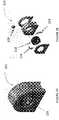
- the handle lock 103can include a core 220, two retaining arms 224, and a release button 228 (the release button is also shown in FIG. 1A ).
- the handle lock core 220can include mating features 229 thereon configured such that the core 220 can mate with the proximal end of the catheter handle and enclose the proximal end of the catheter handle and limit radial handle movement. Axial movement of the catheter handle can be limited by the retaining arms 224 once the handle is fully seated in the lock 103.
- the handle of the cathetercan be inserted into the handle lock 103 such that features of the handle (such as mating wings) fit within the mating keyways 229 of the core 220, thereby allowing for self-alignment of the handle with the drive assembly 100.
- the handlecan push the retaining arms 224 into the open position, as shown in FIG. 3B .
- an extension spring 227 in the handle lock 103can cause the retaining arms 224 to return to a closed position (see FIG. 3C ), preventing the catheter and catheter handle from moving axially and rotationally within the sled.
- the catheter or catheter handlecan be removed from the drive assembly 100 by pushing down on the handle release button 228, which can cause the retaining arms 224 to rotate into the open position, thereby allowing the catheter handle to be removed from the handle lock 103.
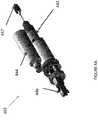
- the rotary optical drive subassembly 102 of the drive assembly 100can include a fiber optic rotating junction (FORJ) 442, a motor 444, an optical connector 446, which can be connected to the drive shaft (and optical fiber) of the catheter, and an optical connector 447, which can connected to the light source.
- the FORJ 442can advantageously serve to provide an optical link between light from a light source and the optical fiber of the catheter.
- the FORJ 442can further advantageously serve to decouple the catheter fiber rotation from light source fiber rotation, i.e., can provide a junction for the catheter's rotating optical fiber and a static optical fiber from the light source.
- the motor 444can be a DC brushless motor with integrated speed controller.
- the motor 444can be configured to drive the FORJ through a belt-pulley system.
- the FORJ 442can be configured to drive the rotation of the drive shaft and optical fiber of the catheter through the optical connector 446, which can connect directly to the drive shaft.
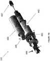
- the motor 444 and the FORJ 442can have pulleys 445, 443, respectively, that can be connected by a belt (not shown).
- the FORJ 442turns (shown by arrow C).
- the FORJ 442can be rigidly connected to the distal optical connector 446 through mechanical couplings. Therefore, as the FORJ 442 turns, the optical connector 446 turns.
- the distal optical connectoris mechanically locked to the catheter optical connector, which is connected to the drive shaft and optical fiber of the catheter. Therefore, as the distal optical connector 446 rotates, so does the catheter drive shaft and optical fiber.
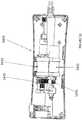
- the linear slide subassembly 104includes a linear slide 552 having a stationary portion 554 connected to the housing 101 of the drive assembly 100 and a translatable portion 556 movable relative to the housing 101 of the drive assembly.
- the rotary optical drive subassembly 102can rest on, and be fixedly attached to, the translatable portion 556 of the linear slide 552.
- the rotary optical drive subassembly 102can slide axially (proximally and distally) relative to the stationary portion 554 of the linear slide 552 (and thus relative to the housing 101), as shown by the arrow A in FIG. 5A .
- the linear slide assemblycan thus translate axially in concert with axial movement of the catheter's drive shaft and optical fiber (such as for exposing the cutter or packing the nosecone).
- the rotary optical subassembly 102can move simultaneously, thereby maintaining the optical connection between the catheter and the light source.
- the linear slidecan include a space for slack in the optical fiber therein.
- slack in the optical fibercan coil around within the inner perimeter of the housing 101. The slack in the optical fiber can ensure that movement of the rotary optical subassembly 102 distally will not pull the optical fiber out of the optical connection 447 with the light source (as the optical fiber can be axially fixed at the optical connection 447).
- movement of the rotary optical subassembly 102can be activated through the optical connection 446 via an activation mechanism on the handle or the catheter.
- the rotary optical subassembly 102can be passively moved as the parts of the catheter or handle are actively moved.
- a release lever 145can be configured to either allow or
- the axial translation of the rotary optical drive assembly 104 and the drive shaftcan occur relative to the sled housing 101 and the catheter outer shaft and handle (connected to the housing 101), all of which can remain stationary. Maintaining a stationary outer shaft ensures that the outer shaft can remain axially and rotationally stabilized in the vessel while the cutter deflection and/or tissue packing occur, thereby ensuring that the physician does not lose the desired catheter position relative to the vessel.
- the drive assembly 100can advantageously provide a therapeutic amount of torque to the drive shaft/cutter of a catheter while also providing the required speed of rotation for imaging, such as OCT imaging.
- the drive assembly 100can provide 0.00353-0.106 Nm (0.5 to 15 ounce inches) of torque, such as 0.00353-0.0706 Nm (0.5 to 10 ounce inches), such as 0.00706-0.0353 Nm (1 to 5 ounce inches), such as approximately 0.0141 Nm (2 ounce inches) of torque.
- a drive assemblycan be configured to provide only rotation of a drive shaft and simultaneous rotation of an optical fiber (and not translation of either).
- Such drive assembliescould be used, for example, with: (1) a catheter having an imaging sensor and a cutter that are driven by the same drive shaft where the drive shaft can be translated proximally or distally to pack tissue and/or expose the cutter (and where the translation mechanism is provided in the handle); or (2) a catheter having a separately rotatable imaging and cutting shaft.
- the drive assembly 100 described abovecan be used without the linear drive subassembly 102 to provide only rotation.
- Another drive assembly 1400is shown with respect to FIGS. 6-15 that can be configured to provide rotation of a drive shaft and rotation of an optical fiber of an imaging catheter.
- the drive assembly 1400can include a housing 1402 having a rotary optical subassembly 1411, a control board (not shown), and a position sensor 1433 therein.
- the drive assembly 1400can further include a connection 1401 to a cable 1403 extending to the light source as well as a handle lock 1405 to connect to a catheter handle.
- a power button 1407 on the housing 1402can be used to toggle power to the drive assembly 1400.
- the handle lock 1405can be a mechanical interface which secures a catheter handle of an imaging catheter to the drive assembly 1400 during use.
- the handle lock 1405can include a core 1407 to limit radial handle movement by encircling the proximal end of the catheter handle.
- the core 1407can be held in place in the drive assembly 1400 by mating features 1409 at the top and bottom of the housing 1402.
- the catheter handlecan be locked in its axial position by a handle lock bar 1411 that is loaded with a spring 1413.
- mating featuresuch as a wing
- mating keyway 1417To lock the handle into the drive assembly 100, mating feature (such as a wing) on the handle is aligned with a mating keyway 1417.
- the keyway 1415 on the handleWhen inserting the catheter into the drive assembly, the keyway 1415 on the handle initially aligns the spring-loaded handle lock bar boss 1419 with the aligned with a mating keyway 1417.
- the keyway 1415 on the handleWhen inserting the catheter into the drive assembly, the keyway 1415 on the handle initially aligns the spring-loaded handle lock bar boss 1419 with the keyway 1417, thereby allowing g for self-alignment of the handle with the drive assembly 1400.
- the handle lock bar boss 1419eventually slides into a locking channel 1421 on the handle, securing the handle position.
- the handle release button 1423which can be attached to the handle lock bar 1411.
- the handle lock bar 1411slides back into alignment with the keyway 1417, allowing the handle to be removed. Movement of the handle lock bar 1411 and button 1423 is otherwise restrained by the housing 1402.
- the rotary optical subassembly 1411includes a fiber optic rotating junction (FORJ) 1421 and a motor 1432, such as a DC brushless motor with integrated speed control.
- the rotary optical subassembly 1411can be designed similar to the rotary optical subassembly 102 described above and can thus serve to both: (1) decouple the catheter fiber rotation from the source of rotation; and (2) drive the catheter's cutting and imaging elements through the optical connector 1427.
- the motor 1432drives the FORJ 1421 through pulleys 1431, 1435 which are connected by a belt (not shown). In turn, the FORJ 1421 drives the rotation of the drive shaft and optical fiber of the catheter through the optical connector 1427.
- the drive assembly 1400can further include an automatic alignment feature to align the catheter properly with respect to the drive assembly 1400. Cleaving the optical fiber of the catheter and the optical fiber of the drive assembly at an angle (e.g. 8 degrees) is desirable to reduce back-reflection at the interface between the optical fibers. Immediate physical connection is also desirable to reduce transmission losses. As such, the optical fibers should be aligned at exactly the right orientation (with the angled cleaves lined up) to allow the light to travel from one optical fiber). If an automatic alignment feature is created to properly orient these fibers with respect to one another, then the separate step of manually connecting the optical assemblies of the catheter/handle and the drive assembly can be eliminated.
- an automatic alignment featureis created to properly orient these fibers with respect to one another, then the separate step of manually connecting the optical assemblies of the catheter/handle and the drive assembly can be eliminated.
- the drive assembly 1400can be automatically aligned with the catheter handle through alignment mechanisms on both the drive assembly 1400 and on the catheter handle.
- the drive assembly 1400can include an orientation sensor 1433 configured to sense the rotational position of the optical connector 1427.
- the sensor 1433can be a slot sensor (or optical fork sensor) configured to detect a flag 1442 on the optical connector 1427.
- the sensor 1433(in this case, a slot sensor) can thus detect as the flag 1442 passes therethrough. Because the flag 1442 is in a set position relative to the connection mechanisms of the optical connector 1427, the detection of the flag 1442 can allow for the determination of the rotational position or orientation of the connection mechanisms.
- a control board in the drive assembly 1400can use feedback from the optical sensor 1433 to stop the motor 1432 such that the optical connector 1427 is always in the same position, such as the top-dead center position shown in FIG. 15 . That is, after the user powers the drive assembly 1400 off, the control board can keep the motor 1432 and FORJ 1421 running at a constant speed until the exact position of the optical connector 1427 is identified based upon readings from the sensor 1433. The control board can then cut power to the motor such that, based upon the sensed position and the known length of time that the FORJ takes to stop after power is cut, the optical connector 1427 will stop in a predetermined position. The predetermine position can be the same every time that the drive assembly 1400 is used.
- the optical connector 1427can mate with a handle or catheter that is preset in a corresponding mating optical position (such as set by the manufacturer).
- a handle or catheterthat is preset in a corresponding mating optical position (such as set by the manufacturer).
- Such a featurecan provide for an automatic optical connection when the drive assembly is physically attached to the catheter or handle in a set orientation, such as with the locking mechanism described above.
- the physical relationship between the drive assembly 1400 and the handle or cathetercan be set, such as with a mating tooth (e.g. a protruding tooth or rib on the drive assembly and a recessed slot on the catheter handle).
- the drive assembly 1400can be less than 1.36 kg ( 3 Ibs ), such as less than 0.9 kg (2 lbs), such as approximately 0.68 kg (1.5 lbs) in weight. Further, the drive assembly can be less than 1474 cc (90 cubic inches), such as less than 1229 cc (75 cubic inches), such as less than 1065 cc (65 cubic inches), for example approximately 1032 cc (63 cubic inches) in volume. In one embodiment, the drive assembly 1400 can measure 228 mm by 88,9 mm by 50.8 mm ( 9" by 3.5" by 2").
- FIGS. 17-19Another drive assembly 1700 is shown with respect to FIGS. 17-19 that can be configured to provide rotation of a drive shaft and rotation of an optical fiber of an imaging catheter.
- the drive assembly 1700can include a housing 1701, an optical connector 1721 configured to connect the drive assembly 1700 to a light source, a power connector 1723 configured to connect the drive assembly 1700 to a power source, and a connection 1755 (such as the handle locks described above) configured to connect the drive assembly 1700 to a handle 900 of an imaging catheter.
- the drive assembly 1700can include a rotating optical drive subassembly 1811 including a FORJ 1813, a motor 1815, and an optical connector 1817, such as an MU adaptor, configured to connect the FORJ with the catheter drive shaft and optical fiber.
- the shaft of the motor 1815can be hollow so as to allow the FORJ 1813 to extend therethrough (i.e., the motor 1815 and the FORJ 1813 can be coaxial).
- the FORJ 1813is entirely on the stationary side of the motor, with only a rotating fiber 1993 passing through the motor 1815.
- the FORJ 1813works through the motor 1815, with a stationary fiber on one side, light passing through the hollow shaft, and a rotating fiber on the far side.
- the FORJ 1813is on the rotating side of the motor 1815 and a stationary fiber inside a stationary tube passes through the motor 1815.
- the motor 1815can further be configured to provide sufficient torque without gearing.
- the connector 1817can be configured to as to minimize the moment of inertia and swept volume to reduce vibration.
- the dimensions of the drive assembly 1700can be reduced.
- the drive assembly 1700can have a volume of less than 655.5 cc (40 cubic inches), such as less than 328 cc (20 cubic inches), such as less than 295 cc (18 cubic inches), such as approximately 229-262 cc (14-16 cubic inches).
- the drive assembly 1700can have a length of less than or equal to 228 mm (nine inches) and a diameter of less than or equal to 63.5 mm (2.5 inches), such as approximately 31.75 mm (1.25 inches).
- the drive assembly 1700is approximately 228 mm long by 38.1 mm in diameter (9" long by 1.5" in diameter), 228 mm long by 31.75 mm in diameter (9" long by 1.25" in diameter), or 178 mm long by 31.75 mm in diameter (7" long by 1.25" in diameter).
- the drive assembly 1700can include a mechanism for automatically/mechanically aligning the drive assembly 1700 with the handle or catheter, such as a top dead center sensor.
- the FORJ 1815(and any FORJ described herein) can include a rotating portion 1991 with a rotating fiber 1993 and a rotating lens 1995 and a stationary portion 1997 with a stationary fiber 1998 and a stationary lens 1999.
- the drive assemblies described hereincan include a magnetic handle locking assembly 2000 in place of the locking mechanisms described above.
- the locking assembly 2000can be configured to mate with a magnetic assembly 2050 on the catheter handle.
- the locking assembly 2000can include a magnetic housing 2002 and a female fiber optic connector 2004, such as an FC-APCC, which can be configured to mate with a catheter magnetic housing 2052 and a male fiber optic connector 2054, such as an FC-APC 2054 (though in other embodiments, the positions of the female/male FC-APCs could be reversed).
- the housings 2002, 2052can include slots 2006a,b and 2056a,b configured to hold magnets therein. The magnets in each slot 2006a,b of the drive assembly can be of opposite polarity to one another.
- the magnets in slots 2006a,bcan be of opposite polarity to the magnets in the adjacent catheter locking assembly (e.g., magnets in slot 2006a can be of opposite polarity to magnets in slot 2056a).
- the opposing polarities of the magnetscan cause the assemblies 2000, 2050 to rotate into the proper alignment, thus providing an automatic alignment feature for the drive assemblies described herein with a corresponding imaging catheter handle.
- the locking assembly 2000can further include mechanical teeth and mating slots 2063a,b therein configured to hold the magnetic assemblies 2000, 2050 together as one or the other is rotated, thereby transmitting torque from one assembly 2000 to the other 2050.
- the magnetic handle locking assembly 2000can allow insertion of the catheter into the drive assembly with a single hand without requiring a secondary fiber connection, in contrast to other drive assemblies where the optical connection was manually made after the mechanical connection was made.
- the drive assemblies described hereincan be reusable, advantageously reducing the cost and complexity associated with imaging catheters.
- the drive assemblies described hereincan advantageously be introduced into the sterile field through use of a sterile bag.
- a non-sterile operatorusing sterile technique, can open the sterile bag pouch and present the sterile bag to the sterile operator.
- the sterile operatorcan remove the bag from the sterile pouch and pass the catheter handle through the sterile bag.
- the non-sterile operatorcan then present the drive assembly 100 to the sterile operator.
- the sterile operatorcan connect the catheter handle into the handle lock until the catheter is locked into place.
- the non-sterile operatorcan connect the optical connector 446 to the catheter and close the access door 107 of housing 101.
- the non-sterile operatorcan further grab the outside of the bag and pull the bag back over the drive assembly and attached cables.
- the sterile operatorcan position the bagged drive assembly in the sterile field where desired.
- the drive assemblycan be activated through toggling of the power switch. Similar methodologies can be used with the drive assemblies 1400 and 1700 described herein, though the automatic optical connection between the drive assemblies 1400 and 1700 advantageously eliminates the step of creating a separate optical connection (such as by opening the access door 107 of the drive assembly 100).
- the drive assemblies described hereincan be used to transmit light from a source, such as for optical coherence tomography.
- Exemplary imaging systems that can be used with the drive assembliesare described in copending Patent Applications: U.S. Patent Application No. 12/790,703 , titled “OPTICAL COHERENCE TOMOGRAPHY FOR BIOLOGICAL IMAGING," filed 5/28/2010, Publication No. US-2010-0305452-A1 ; U.S. Patent Application No. 12/829,267 , titled “CATHETER- BASED OFF-AXIS OPTICAL COHERENCE TOMOGRAPHY IMAGING SYSTEM,” filed 7/1/2010, Publication No. US-2010-0021926-A1 ; and International Patent Application titled “OPTICAL COHERENCE TOMOGRAPHY WITH GRADED INDEX FIBER FOR BIOLOGICAL IMAGING,” filed herewith.
- the drive assemblies described hereincan be used with a variety of different catheters, such as atherectomy catheters with imaging.
- Exemplary catheters and/or handles that can be used with the drive assemblies described hereinare set forth in copending Patent Applications: U.S. Patent Application No. 12/829,277 , published as US2011004107 , titled “ATHERECTOMY CATHETER WITH LATERALLY-DISPLACEABLE TIP,” filed 7/1/2010, Publication No. US-2011-0004107-A1 ; U.S. Patent Application No. 13/175,232 , titled “ATHERECTOMY CATHETERS WITH LONGITUDINALLY DISPLACEABLE DRIVE SHAFTS,” filed 7/1/2011, Publication No.
- references to a structure or feature that is disposed "adjacent" another featuremay have portions that overlap or underlie the adjacent feature.
- the devicemay be otherwise oriented (rotated 90 degrees or at other orientations) and the spatially relative descriptors used herein interpreted accordingly.
- the terms “upwardly”, “downwardly”, “vertical”, “horizontal” and the likeare used herein for the purpose of explanation only unless specifically indicated otherwise.
- first and secondmay be used herein to describe various features/elements, these features/elements should not be limited by these terms, unless the context indicates otherwise. These terms may be used to distinguish one feature/element from another feature/element. Thus, a first feature/element discussed below could be termed a second feature/element, and similarly, a second feature/element discussed below could be termed a first feature/element without departing from the teachings of the present invention.
- a numeric valuemay have a value that is +/- 0.1% of the stated value (or range of values), +/- 1% of the stated value (or range of values), +/- 2% of the stated value (or range of values), +/- 5% of the stated value (or range of values), +/- 10% of the stated value (or range of values), etc. Any numerical range recited herein is intended to include all sub-ranges subsumed therein.
Landscapes
- Health & Medical Sciences (AREA)
- Life Sciences & Earth Sciences (AREA)
- Surgery (AREA)
- General Health & Medical Sciences (AREA)
- Public Health (AREA)
- Veterinary Medicine (AREA)
- Nuclear Medicine, Radiotherapy & Molecular Imaging (AREA)
- Animal Behavior & Ethology (AREA)
- Molecular Biology (AREA)
- Engineering & Computer Science (AREA)
- Biomedical Technology (AREA)
- Heart & Thoracic Surgery (AREA)
- Medical Informatics (AREA)
- Physics & Mathematics (AREA)
- Optics & Photonics (AREA)
- Biophysics (AREA)
- Radiology & Medical Imaging (AREA)
- Pathology (AREA)
- Vascular Medicine (AREA)
- Surgical Instruments (AREA)
- Investigating Or Analysing Materials By Optical Means (AREA)
- Endoscopes (AREA)
- Laser Surgery Devices (AREA)
Description
- A significant body of scientific and clinical evidence supports atherectomy as a viable primary or adjunctive therapy prior to stenting for the treatment of occlusive arterial disease. Atherectomy offers a simple mechanical advantage over alternative therapies. By removing the majority of plaque mass (debulking), a larger initial lumen is created. As a result, stent deployment is greatly enhanced. Moreover, there are advantages to atherectomy related to the arterial healing response. When circumferential radial forces are applied to the vasculature, as in the case of angioplasty or stenting, the plaque mass is displaced, forcing the vessel wall to stretch dramatically. This stretch induces injury which is a known stimulus for the cellular in-growth that leads to restenosis. By removing the disease with minimal force applied to the vessel and reducing the plaque burden prior to stent placement, large gains in lumen size can be created with decreased vessel wall injury and limited elastic recoiling. These effects have been shown to generate better acute results and lower restenosis rates.
- Traditional atherectomy devices have been plagued by a number of problems that have severely limited market adoption of these devices. A significant concern in adopting these devices is that they tend to require the use of large, cumbersome, and expensive drive assemblies to control the rotation and/or axial translation of the atherectomy cutter. The drive assemblies described herein may overcome some of these hurdles.
US 2006/093276 discloses an optical system having a stationary optical fiber, a rotatable optical fiber, and a rotary junction comprising a pair of collimators that allows collimated light to be transmitted between the stationary optical fiber and the rotatable optical fiber.- According to the present invention, there is provided a drive assembly as defined in the appended Claim 1. Described herein are drive assemblies for catheters having a rotatable cutter and on-board imaging.
- In general, in one embodiment, a drive assembly for driving an imaging catheter has a rotatable fiber and a rotatable drive shaft. The drive assembly includes a fiber optic rotating junction having a stationary portion with a stationary fiber therein and a rotatable portion with a rotatable fiber therein. The drive assembly includes a first optical connection configured to connect the stationary fiber with a light source. The drive assembly includes a motor configured to rotate the rotatable portion of the fiber optic rotating junction. The drive assembly includes a second optical connection configured to connect the rotatable portion of the fiber optic rotating junction with both the drive shaft and the rotatable fiber of the imaging catheter so as to transmit torque from the motor to the drive shaft and the rotatable fiber of the catheter and so as to transmit light from the light source to the rotatable fiber of the catheter. Optionally, the drive assembly includes a sensor configured to detect a rotational position of the fiber optic rotating junction. The drive assembly optionally includes a processor configured to obtain the detected rotational position and stop the motor only when the fiber optic rotating junction is in a predetermined rotational position.
- This and other embodiments can include one or more of the following features. The sensor can be a slot sensor configured to detect a flat on the rotary optical junction. The locking mechanism can include mechanical features to physically align the handle with respect to the drive assembly. The locking mechanism can be configured such that physical alignment of the catheter handle with respect to the drive assembly can further align an optical connection of the handle with the predetermined rotational position of the fiber optic rotating junction. The stationary and rotatable fibers can be configured to transmit an optical coherence tomography signal.
- A method of driving an imaging catheter having a rotatable fiber and a rotatable drive shaft is described but not claimed. The method includes connecting a stationary fiber of a stationary portion of a fiber optic rotating junction in a drive assembly with a light source; connecting a rotatable fiber of the fiber optic rotating junction with the drive shaft and the rotatable fiber of the imaging catheter; rotating the rotatable portion of a fiber optic rotating junction with a motor in the drive assembly such that both the drive shaft and the rotatable fiber of the imaging catheter rotate and such that light is transmitted from the light source to the rotatable fiber of the imaging catheter; sensing a position of the fiber optic rotating junction; and stopping the motor based upon the sensed position only when the fiber optic rotating junction is in a predetermined rotational position.
- This and other methods can include one or more of the following features. Sensing the position can include sensing the position with a slot sensor. The method can include locking a handle of the imaging catheter into the drive assembly. The locking mechanism can include mechanical features to physically align the catheter handle with respect to the drive assembly. Locking the handle of the imaging catheter into the drive assembly using the mechanical features can align an optical connection of the handle with the predetermined rotational position of the fiber optic rotating junction. The method can further include transmitting an optical coherence tomography signal through the stationary and rotatable fibers.
- In general, in one embodiment, a drive assembly for driving an imaging catheter having a rotatable fiber and a rotatable drive shaft includes a drive assembly housing. The drive assembly further includes a fiber optic rotating junction within the housing having a stationary portion with a stationary fiber therein and a rotatable portion with a rotatable fiber therein. The drive assembly includes a first optical connection through the housing configured to connect the stationary fiber with a light source. The drive assembly includes a motor within the housing configured to rotate the rotatable portion of the fiber optic rotating junction. The drive assembly includes a second optical connection through the housing configured to connect the rotatable portion of the fiber optic rotating junction with both the drive shaft and the rotatable fiber of the imaging catheter so as to transmit torque from the motor to the drive shaft and the rotatable fiber of the catheter and so as to transmit light from the light source to the rotatable fiber of the catheter. The housing is less than 1.23 litres (75 cubic inches) in volume, and the drive assembly has a total weight of less than 0.9 kg (2 pounds).
- This and other embodiments can include one or more of the following features. The volume can be less than 0.655 litres (40 cubic inches). The volume can be less than 0.323 litres (20 cubic inches). The drive assembly can further include a locking mechanism configured to lock a handle of the imaging catheter to the drive assembly. The stationary and rotatable fibers can be configured to transmit an optical coherence tomography signal.
- In general, in one embodiment, a drive assembly for driving an imaging catheter having a rotatable fiber and a rotatable drive shaft includes a fiber optic rotating junction having a stationary portion with a stationary fiber therein and a rotatable portion with a rotatable fiber therein. The drive assembly includes a first optical connection configured to connect the stationary fiber with a light source. The drive assembly includes a motor configured to rotate the rotatable portion of the fiber optic rotating junction. The motor has a hollow shaft configured to house a portion of the fiber optic rotating junction such that the motor and the fiber optical rotating junction are coaxial. The drive assembly includes a second optical connection configured to connect the rotatable portion of the fiber optic rotating junction with both the drive shaft and the rotatable fiber of the imaging catheter so as to transmit torque from the motor to the drive shaft and the rotatable fiber of the catheter and so as to transmit light from the light source to the rotatable fiber of the catheter.
- This and other embodiments can include one or more of the following features. The rotatable fiber of the fiber optic junction can be housed within the hollow shaft. The drive assembly can further include a locking mechanism that can be configured to lock a handle of the imaging catheter to the drive assembly. The stationary and rotatable fibers can be configured to transmit an optical coherence tomography signal.
- In general, in one embodiment, a drive assembly for driving an imaging catheter having a rotatable fiber and a rotatable drive shaft includes a drive assembly housing. The drive assembly further includes a fiber optic rotating junction within the housing having a stationary portion with a stationary fiber therein and a rotatable portion with a rotatable fiber therein. The drive assembly includes a first optical connection through the housing configured to connect the stationary fiber with a light source. The drive assembly includes a motor in the housing configured to rotate the rotatable portion of the fiber optic rotating junction. The drive assembly includes a linear slide in the housing configured to translate the fiber optic rotating junction axially within the housing. The drive assembly includes a second optical connection through the housing configured to connect the rotatable portion of the fiber optic rotating junction with both the drive shaft and the rotatable fiber of the imaging catheter so as to transmit torque from the motor to the drive shaft and the rotatable fiber and so as to transmit light from the light source to the rotatable fiber of the catheter.
- This and other embodiments can include one or more of the following features. The stationary fiber of the fiber optic rotating junction can be axially fixed at the first optical connection. The stationary fiber of the fiber optic rotating junction can include slack configured to account for translation of the fiber optic rotating junction. The drive assembly can further include a locking mechanism that can be configured to lock a handle of the imaging catheter to the drive assembly. The stationary and rotatable fibers can be configured to transmit an optical coherence tomography signal.
- In general, in one embodiment, a drive assembly for driving an imaging catheter having a rotatable fiber and a rotatable drive shaft, includes a fiber optic rotating junction having a stationary portion with a stationary fiber therein and a rotatable portion with a rotatable fiber therein. The drive assembly includes a first optical connection configured to connect the stationary fiber with a light source. The drive assembly includes a motor configured to rotate the rotatable portion of the fiber optic rotating junction. The drive assembly includes a second optical connection configured to connect the rotatable portion of the fiber optic rotating junction with both the drive shaft and the rotatable fiber of the imaging catheter so as to transmit torque from the motor to the drive shaft and the rotatable fiber of the catheter and so as to transmit light from the light source to the rotatable fiber of the catheter. The drive assembly includes a magnetic locking mechanism configured to automatically align the second optical connection with the drive shaft and the rotatable fiber of the imaging catheter.
- Exemplary methods of using these drive systems are also described herein.
- The novel features of the invention are set forth in the claims that follow. Claim 1 defines the invention and the dependent claims disclose further embodiments. No surgical methods form part of the invention. A better understanding of the features and advantages of the present invention will be obtained by reference to the following detailed description that sets forth illustrative embodiments, in which the principles of the invention are utilized, and the accompanying drawings of which:
FIG. 1A shows a variation of the drive assembly configured to drive an imaging catheter with a rotary cutter. The drive assembly includes a motor to drive the catheter cutter and a linear slide assembly to translate an optical assembly with a drive shaft.FIG. 1B shows the drive assembly with the outer housing removed to exhibit the interior components.FIG. 2A shows a handle lock of the drive assembly ofFIGS. 1A and1B .FIG. 2B shows an exploded view of the drive assembly ofFIG. 2A .FIG. 3A shows the interaction between the handle lock ofFIG. 2A and a catheter handle.FIG. 3B shows the handle lock ofFIG. 2A in an open position.FIG. 3C shows the handle lock ofFIG. 2A in a closed position.FIGS. 4A and4B show the rotary optical drive subassembly of the drive assembly ofFIGS. 1A and1B .FIG. 5A shows activation of the linear slide of the rotary optical drive subassembly ofFIGS. 4A and4B in a tissue packing position.FIG. 5B shows activation of the linear slide of the rotary optical drive subassembly ofFIGS. 4A and4B in a tissue cut position.FIG. 6 shows the outer housing of another exemplary drive assembly.FIGS.7 and8 show the drive assembly ofFIG. 6 with the housing removed to show the inner components and subassemblies.FIGS. 9A and 9B show a close-up of the distal portion of the drive assembly shown inFIGS. 7 and8 , including the locking mechanism to connect a handle to the drive assembly ofFIG. 6 .FIG. 10 is a top view of the locking mechanism ofFIGS. 7 and8 .FIGS. 11A and11B show front and side view of the locking mechanism ofFIGS. 7 and8 .FIGS. 12 and13 show the drive assembly ofFIGS. 7 and8 , including an exemplary rotary optical drive assembly.FIGS. 14A and14B show a close-up of an optical sensor configured to align a drive assembly (such as the drive assembly ofFIGS. 7 and8 ) with a catheter or catheter handle.FIG. 15 shows an axial view of a handle lock of the drive assembly ofFIG. 7 and8 with the optical connector aligned in top-dead-center position.FIG. 16 shows a magnetic connector for connecting a catheter to a drive assembly.FIG. 17 shows another exemplary drive assembly.FIGS. 18A-18C show the drive assembly ofFIG. 17 with the housing removed.FIG. 19 is a cross-sectional diagrammatic view of the rotary optical drive subassembly ofFIGS. 18A-18C .- Described herein are reusable drive assemblies configured to be attached to an imaging catheter, such as an atherectomy catheter. In general, the drive assemblies can include a motor to rotate both a drive shaft of the catheter and a rotating fiber of the catheter. The drive assemblies herein can further include an optical pass-through to transfer light from a light source to the rotating fiber of the catheter, such as for optical coherence tomography (OCT) imaging. The optical pass-through can include a fiber optic rotating junction having a stationary portion with a stationary fiber therein and a rotatable portion with a rotatable fiber therein. The drive assembles can be configured to attach at the proximal end to a light source and at the distal end to a catheter.
- In some embodiments, a drive assembly can be configured to provide rotation of a drive shaft, simultaneous rotation of an optical fiber, translation of the drive shaft, and simultaneous translation of the fiber. Such drive assemblies could be used, for example, with a catheter having an imaging sensor and a cutter that are driven by the same drive shaft where the drive shaft can be translated proximally or distally to pack tissue and/or expose the cutter.
- For example, referring to
FIGS. 1A-5B , adrive assembly 100 can be configured to provide rotation of a drive shaft, rotation of an optical fiber, translation of the drive shaft, and translation of the fiber of an imaging catheter. - As shown in
FIGS. 1A-1B , thedrive assembly 100 can include a housing 101 (having anaccess door 107 therein) and ahandle lock 103, to connect thedrive assembly 100 to a - As shown in
FIGS. 1A-1B , thedrive assembly 100 can include a housing 101 (having anaccess door 107 therein) and ahandle lock 103, to connect thedrive assembly 100 to a catheter handle. As shown inFIG. 1B , thedrive assembly 100 can further include a rotaryoptical drive subassembly 102 configured to provide rotation to the drive shaft and optical fiber of a catheter and alinear slide subassembly 104 configured to provide translation of the drive shaft and optical fiber of the catheter used with thedrive assembly 100. Thedrive assembly 100 can be connected at a proximal end to the light source. A power source can connected to thedrive assembly 100 to provide the driving power. Apower button 109 can be used to turn the power to turn thedrive assembly 100 on and off. - The
handle lock 103 can provide a mechanical interface to secure the catheter handle to thedrive assembly 100 during use. In one embodiment, as shown inFIG. 2B , thehandle lock 103 can include acore 220, two retainingarms 224, and a release button 228 (the release button is also shown inFIG. 1A ). Thehandle lock core 220 can include mating features 229 thereon configured such that thecore 220 can mate with the proximal end of the catheter handle and enclose the proximal end of the catheter handle and limit radial handle movement. Axial movement of the catheter handle can be limited by the retainingarms 224 once the handle is fully seated in thelock 103. - Referring to
FIG. 3A , to engage the retainingarms 224, the handle of the catheter can be inserted into thehandle lock 103 such that features of the handle (such as mating wings) fit within themating keyways 229 of thecore 220, thereby allowing for self-alignment of the handle with thedrive assembly 100. Once inserted, the handle can push the retainingarms 224 into the open position, as shown inFIG. 3B . After the mating features of the handle, such as wings, pass fully through the retainingarms 224, anextension spring 227 in thehandle lock 103 can cause the retainingarms 224 to return to a closed position (seeFIG. 3C ), preventing the catheter and catheter handle from moving axially and rotationally within the sled. After use, the catheter or catheter handle can be removed from thedrive assembly 100 by pushing down on thehandle release button 228, which can cause the retainingarms 224 to rotate into the open position, thereby allowing the catheter handle to be removed from thehandle lock 103. - Referring to
FIG. 4A , the rotaryoptical drive subassembly 102 of thedrive assembly 100 can include a fiber optic rotating junction (FORJ) 442, amotor 444, anoptical connector 446, which can be connected to the drive shaft (and optical fiber) of the catheter, and anoptical connector 447, which can connected to the light source. TheFORJ 442 can advantageously serve to provide an optical link between light from a light source and the optical fiber of the catheter. TheFORJ 442 can further advantageously serve to decouple the catheter fiber rotation from light source fiber rotation, i.e., can provide a junction for the catheter's rotating optical fiber and a static optical fiber from the light source. In one embodiment, themotor 444 can be a DC brushless motor with integrated speed controller. In use, themotor 444 can be configured to drive the FORJ through a belt-pulley system. In turn, theFORJ 442 can be configured to drive the rotation of the drive shaft and optical fiber of the catheter through theoptical connector 446, which can connect directly to the drive shaft. - Thus, referring to
FIG. 4B , themotor 444 and theFORJ 442 can havepulleys motor 444 turns (shown by arrow B), theFORJ 442 turns (shown by arrow C). TheFORJ 442 can be rigidly connected to the distaloptical connector 446 through mechanical couplings. Therefore, as theFORJ 442 turns, theoptical connector 446 turns. When the catheter handle is attached, the distal optical connector is mechanically locked to the catheter optical connector, which is connected to the drive shaft and optical fiber of the catheter. Therefore, as the distaloptical connector 446 rotates, so does the catheter drive shaft and optical fiber. - Referring to
FIGS. 5A and5B , thelinear slide subassembly 104 includes alinear slide 552 having astationary portion 554 connected to thehousing 101 of thedrive assembly 100 and atranslatable portion 556 movable relative to thehousing 101 of the drive assembly. The rotaryoptical drive subassembly 102 can rest on, and be fixedly attached to, thetranslatable portion 556 of thelinear slide 552. As a result, the rotaryoptical drive subassembly 102 can slide axially (proximally and distally) relative to thestationary portion 554 of the linear slide 552 (and thus relative to the housing 101), as shown by the arrow A inFIG. 5A . The linear slide assembly can thus translate axially in concert with axial movement of the catheter's drive shaft and optical fiber (such as for exposing the cutter or packing the nosecone). Thus, as shown inFIGS. 5A andB , if the drive shaft and thus the cutter need to be moved distally (FIG. 5A ) and/or proximally (FIG. 5B ), such as to activate the nosecone or cutter deflection and/or pack tissue into the nosecone, the rotaryoptical subassembly 102 can move simultaneously, thereby maintaining the optical connection between the catheter and the light source. - The linear slide can include a space for slack in the optical fiber therein. For example, slack in the optical fiber can coil around within the inner perimeter of the
housing 101. The slack in the optical fiber can ensure that movement of the rotaryoptical subassembly 102 distally will not pull the optical fiber out of theoptical connection 447 with the light source (as the optical fiber can be axially fixed at the optical connection 447). - In some embodiments, movement of the rotary
optical subassembly 102 can be activated through theoptical connection 446 via an activation mechanism on the handle or the catheter. Thus, the rotaryoptical subassembly 102 can be passively moved as the parts of the catheter or handle are actively moved. Arelease lever 145 can be configured to either allow or - The axial translation of the rotary
optical drive assembly 104 and the drive shaft can occur relative to thesled housing 101 and the catheter outer shaft and handle (connected to the housing 101), all of which can remain stationary. Maintaining a stationary outer shaft ensures that the outer shaft can remain axially and rotationally stabilized in the vessel while the cutter deflection and/or tissue packing occur, thereby ensuring that the physician does not lose the desired catheter position relative to the vessel. - The
drive assembly 100 can advantageously provide a therapeutic amount of torque to the drive shaft/cutter of a catheter while also providing the required speed of rotation for imaging, such as OCT imaging. For example, thedrive assembly 100 can provide 0.00353-0.106 Nm (0.5 to 15 ounce inches) of torque, such as 0.00353-0.0706 Nm (0.5 to 10 ounce inches), such as 0.00706-0.0353 Nm (1 to 5 ounce inches), such as approximately 0.0141 Nm (2 ounce inches) of torque. - In some embodiments, a drive assembly can be configured to provide only rotation of a drive shaft and simultaneous rotation of an optical fiber (and not translation of either). Such drive assemblies could be used, for example, with: (1) a catheter having an imaging sensor and a cutter that are driven by the same drive shaft where the drive shaft can be translated proximally or distally to pack tissue and/or expose the cutter (and where the translation mechanism is provided in the handle); or (2) a catheter having a separately rotatable imaging and cutting shaft.
- For example, the
drive assembly 100 described above can be used without thelinear drive subassembly 102 to provide only rotation. Anotherdrive assembly 1400 is shown with respect toFIGS. 6-15 that can be configured to provide rotation of a drive shaft and rotation of an optical fiber of an imaging catheter. - Referring to
FIGS. 6-8 , thedrive assembly 1400 can include ahousing 1402 having a rotaryoptical subassembly 1411, a control board (not shown), and aposition sensor 1433 therein. Thedrive assembly 1400 can further include aconnection 1401 to acable 1403 extending to the light source as well as ahandle lock 1405 to connect to a catheter handle. Apower button 1407 on thehousing 1402 can be used to toggle power to thedrive assembly 1400. - Referring to
FIGS. 9A-11B , thehandle lock 1405 can be a mechanical interface which secures a catheter handle of an imaging catheter to thedrive assembly 1400 during use. Thehandle lock 1405 can include acore 1407 to limit radial handle movement by encircling the proximal end of the catheter handle. Thecore 1407 can be held in place in thedrive assembly 1400 bymating features 1409 at the top and bottom of thehousing 1402. The catheter handle can be locked in its axial position by ahandle lock bar 1411 that is loaded with aspring 1413. To lock the handle into thedrive assembly 100, mating feature (such as a wing) on the handle is aligned with amating keyway 1417. When inserting the catheter into the drive assembly, the keyway 1415 on the handle initially aligns the spring-loaded handle lock bar boss 1419 with the aligned with amating keyway 1417. When inserting the catheter into the drive assembly, the keyway 1415 on the handle initially aligns the spring-loaded handle lock bar boss 1419 with thekeyway 1417, thereby allowing g for self-alignment of the handle with thedrive assembly 1400. As the handle is inserted further, the handle lock bar boss 1419 eventually slides into alocking channel 1421 on the handle, securing the handle position. To release the handle, the user pushes thehandle release button 1423, which can be attached to thehandle lock bar 1411. As a result, thehandle lock bar 1411 slides back into alignment with thekeyway 1417, allowing the handle to be removed. Movement of thehandle lock bar 1411 andbutton 1423 is otherwise restrained by thehousing 1402. - Referring to
FIGS. 12-13 , the rotaryoptical subassembly 1411 includes a fiber optic rotating junction (FORJ) 1421 and amotor 1432, such as a DC brushless motor with integrated speed control. The rotaryoptical subassembly 1411 can be designed similar to the rotaryoptical subassembly 102 described above and can thus serve to both: (1) decouple the catheter fiber rotation from the source of rotation; and (2) drive the catheter's cutting and imaging elements through theoptical connector 1427. Themotor 1432 drives theFORJ 1421 throughpulleys 1431, 1435 which are connected by a belt (not shown). In turn, theFORJ 1421 drives the rotation of the drive shaft and optical fiber of the catheter through theoptical connector 1427. - The
drive assembly 1400 can further include an automatic alignment feature to align the catheter properly with respect to thedrive assembly 1400. Cleaving the optical fiber of the catheter and the optical fiber of the drive assembly at an angle (e.g. 8 degrees) is desirable to reduce back-reflection at the interface between the optical fibers. Immediate physical connection is also desirable to reduce transmission losses. As such, the optical fibers should be aligned at exactly the right orientation (with the angled cleaves lined up) to allow the light to travel from one optical fiber). If an automatic alignment feature is created to properly orient these fibers with respect to one another, then the separate step of manually connecting the optical assemblies of the catheter/handle and the drive assembly can be eliminated. - For example, referring to
FIGS. 14A-14B , thedrive assembly 1400 can be automatically aligned with the catheter handle through alignment mechanisms on both thedrive assembly 1400 and on the catheter handle. Thus, in one embodiment, thedrive assembly 1400 can include anorientation sensor 1433 configured to sense the rotational position of theoptical connector 1427. For example, as shown inFIGS. 14A-14B , thesensor 1433 can be a slot sensor (or optical fork sensor) configured to detect aflag 1442 on theoptical connector 1427. The sensor 1433 (in this case, a slot sensor) can thus detect as theflag 1442 passes therethrough. Because theflag 1442 is in a set position relative to the connection mechanisms of theoptical connector 1427, the detection of theflag 1442 can allow for the determination of the rotational position or orientation of the connection mechanisms. - When the user powers the
drive assembly 1400 off, a control board in thedrive assembly 1400 can use feedback from theoptical sensor 1433 to stop themotor 1432 such that theoptical connector 1427 is always in the same position, such as the top-dead center position shown inFIG. 15 . That is, after the user powers thedrive assembly 1400 off, the control board can keep themotor 1432 andFORJ 1421 running at a constant speed until the exact position of theoptical connector 1427 is identified based upon readings from thesensor 1433. The control board can then cut power to the motor such that, based upon the sensed position and the known length of time that the FORJ takes to stop after power is cut, theoptical connector 1427 will stop in a predetermined position. The predetermine position can be the same every time that thedrive assembly 1400 is used. - Advantageously, if the
optical connector 1427 always stops in the same position, it can mate with a handle or catheter that is preset in a corresponding mating optical position (such as set by the manufacturer). Such a feature can provide for an automatic optical connection when the drive assembly is physically attached to the catheter or handle in a set orientation, such as with the locking mechanism described above. In some embodiments, the physical relationship between thedrive assembly 1400 and the handle or catheter can be set, such as with a mating tooth (e.g. a protruding tooth or rib on the drive assembly and a recessed slot on the catheter handle). - Advantageously, the
drive assembly 1400 can be less than 1.36 kg ( 3 Ibs ), such as less than 0.9 kg (2 lbs), such as approximately 0.68 kg (1.5 lbs) in weight. Further, the drive assembly can be less than 1474 cc (90 cubic inches), such as less than 1229 cc (75 cubic inches), such as less than 1065 cc (65 cubic inches), for example approximately 1032 cc (63 cubic inches) in volume. In one embodiment, thedrive assembly 1400 can measure 228 mm by 88,9 mm by 50.8 mm ( 9" by 3.5" by 2"). - Another
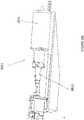
drive assembly 1700 is shown with respect toFIGS. 17-19 that can be configured to provide rotation of a drive shaft and rotation of an optical fiber of an imaging catheter. - Referring to
FIG. 17 , thedrive assembly 1700 can include ahousing 1701, anoptical connector 1721 configured to connect thedrive assembly 1700 to a light source, apower connector 1723 configured to connect thedrive assembly 1700 to a power source, and a connection 1755 (such as the handle locks described above) configured to connect thedrive assembly 1700 to ahandle 900 of an imaging catheter. - As shown in
FIG. 18A-19 thedrive assembly 1700 can include a rotatingoptical drive subassembly 1811 including aFORJ 1813, amotor 1815, and anoptical connector 1817, such as an MU adaptor, configured to connect the FORJ with the catheter drive shaft and optical fiber. The shaft of themotor 1815 can be hollow so as to allow theFORJ 1813 to extend therethrough (i.e., themotor 1815 and theFORJ 1813 can be coaxial). In one embodiment, as shown inFIG. 19 , theFORJ 1813 is entirely on the stationary side of the motor, with only arotating fiber 1993 passing through themotor 1815. In another embodiment, theFORJ 1813 works through themotor 1815, with a stationary fiber on one side, light passing through the hollow shaft, and a rotating fiber on the far side. In yet another embodiment, theFORJ 1813 is on the rotating side of themotor 1815 and a stationary fiber inside a stationary tube passes through themotor 1815. Themotor 1815 can further be configured to provide sufficient torque without gearing. Further, theconnector 1817 can be configured to as to minimize the moment of inertia and swept volume to reduce vibration. - Advantageously, by having the
motor 1815 and theFORJ 1813 coaxial, the dimensions of thedrive assembly 1700 can be reduced. For example, thedrive assembly 1700 can have a volume of less than 655.5 cc (40 cubic inches), such as less than 328 cc (20 cubic inches), such as less than 295 cc (18 cubic inches), such as approximately 229-262 cc (14-16 cubic inches). Further, thedrive assembly 1700 can have a length of less than or equal to 228 mm (nine inches) and a diameter of less than or equal to 63.5 mm (2.5 inches), such as approximately 31.75 mm (1.25 inches). In exemplary embodiments, thedrive assembly 1700 is approximately 228 mm long by 38.1 mm in diameter (9" long by 1.5" in diameter), 228 mm long by 31.75 mm in diameter (9" long by 1.25" in diameter), or 178 mm long by 31.75 mm in diameter (7" long by 1.25" in diameter). - Like the other drive assemblies described herein, when
motor 1815 rotates, theFORJ 1813 can rotate, thereby causing the optical connector 1817 (and thus the drive shaft and optical fiber of the imaging catheter) to rotate. Further, similar to thedrive assembly 1400, thedrive assembly 1700 can include a mechanism for automatically/mechanically aligning thedrive assembly 1700 with the handle or catheter, such as a top dead center sensor. - Referring to
FIG. 19 , it is to be understood that the FORJ 1815 (and any FORJ described herein) can include arotating portion 1991 with arotating fiber 1993 and arotating lens 1995 and astationary portion 1997 with astationary fiber 1998 and astationary lens 1999. - Referring to
FIG. 16 , in some embodiments, the drive assemblies described herein can include a magnetichandle locking assembly 2000 in place of the locking mechanisms described above. The lockingassembly 2000 can be configured to mate with amagnetic assembly 2050 on the catheter handle. - In one embodiment, shown in
FIG. 16 , the lockingassembly 2000 can include amagnetic housing 2002 and a femalefiber optic connector 2004, such as an FC-APCC, which can be configured to mate with a cathetermagnetic housing 2052 and a malefiber optic connector 2054, such as an FC-APC 2054 (though in other embodiments, the positions of the female/male FC-APCs could be reversed). Thehousings slots 2006a,b and 2056a,b configured to hold magnets therein. The magnets in eachslot 2006a,b of the drive assembly can be of opposite polarity to one another. Further, the magnets inslots 2006a,b can be of opposite polarity to the magnets in the adjacent catheter locking assembly (e.g., magnets inslot 2006a can be of opposite polarity to magnets inslot 2056a). Thus, if themagnetic assemblies assemblies - The locking
assembly 2000 can further include mechanical teeth andmating slots 2063a,b therein configured to hold themagnetic assemblies assembly 2000 to the other 2050. - Advantageously, the magnetic
handle locking assembly 2000 can allow insertion of the catheter into the drive assembly with a single hand without requiring a secondary fiber connection, in contrast to other drive assemblies where the optical connection was manually made after the mechanical connection was made. - The drive assemblies described herein can be reusable, advantageously reducing the cost and complexity associated with imaging catheters.
- Further, the drive assemblies described herein can advantageously be introduced into the sterile field through use of a sterile bag. For example, a non-sterile operator, using sterile technique, can open the sterile bag pouch and present the sterile bag to the sterile operator. The sterile operator can remove the bag from the sterile pouch and pass the catheter handle through the sterile bag. The non-sterile operator can then present the
drive assembly 100 to the sterile operator. The sterile operator can connect the catheter handle into the handle lock until the catheter is locked into place. The non-sterile operator can connect theoptical connector 446 to the catheter and close theaccess door 107 ofhousing 101. The non-sterile operator can further grab the outside of the bag and pull the bag back over the drive assembly and attached cables. Finally, the sterile operator can position the bagged drive assembly in the sterile field where desired. The drive assembly can be activated through toggling of the power switch. Similar methodologies can be used with thedrive assemblies drive assemblies access door 107 of the drive assembly 100). - It is to be understood that any of the features of the various exemplary drive assemblies described herein could be substituted or added to other drive assemblies while still lying within the scope of this disclosure.
- The drive assemblies described herein can be used to transmit light from a source, such as for optical coherence tomography. Exemplary imaging systems that can be used with the drive assemblies are described in copending Patent Applications:
U.S. Patent Application No. 12/790,703 US-2010-0305452-A1 ;U.S. Patent Application No. 12/829,267 , titled "CATHETER- BASED OFF-AXIS OPTICAL COHERENCE TOMOGRAPHY IMAGING SYSTEM," filed 7/1/2010, Publication No.US-2010-0021926-A1 ; and International Patent Application titled "OPTICAL COHERENCE TOMOGRAPHY WITH GRADED INDEX FIBER FOR BIOLOGICAL IMAGING," filed herewith. - The drive assemblies described herein can be used with a variety of different catheters, such as atherectomy catheters with imaging. Exemplary catheters and/or handles that can be used with the drive assemblies described herein are set forth in copending Patent Applications:
U.S. Patent Application No. 12/829,277 ,published as US2011004107 , titled "ATHERECTOMY CATHETER WITH LATERALLY-DISPLACEABLE TIP," filed 7/1/2010, Publication No.US-2011-0004107-A1 ;U.S. Patent Application No. 13/175,232 US-2012-0046679-A1 ;U.S. Patent Application No. 13/654,357 U.S. Patent Application No. 13/675,867 - Additional details pertinent to the present invention, including materials and manufacturing techniques, may be employed as within the level of those with skill in the relevant art. Also, it is contemplated that any optional feature of the inventive variations described may be set forth and claimed independently, or in combination with any one or more of the features described herein. Likewise, reference to a singular item, includes the possibility that there are a plurality of the same items present. More specifically, as used herein and in the appended claims, the singular forms "a," "and," "said," and "the" include plural referents unless the context clearly dictates otherwise. It is further noted that the claims may be drafted to exclude any optional element. As such, this statement is intended to serve as antecedent basis for use of such exclusive terminology as "solely," "only" and the like in connection with the recitation of claim elements, or use of a "negative" limitation. Unless defined otherwise herein, all technical and scientific terms used herein have the same meaning as commonly understood by one of ordinary skill in the art to which this invention belongs. The breadth of the present invention is not to be limited by the subject specification, but rather only by the of the appended claims.
- When a feature or element is herein referred to as being "on" another feature or element, it can be directly on the other feature or element or intervening features and/or elements may also be present. In contrast, when a feature or element is referred to as being "directly on" another feature or element, there are no intervening features or elements present. It will also be understood that, when a feature or element is referred to as being "connected", "attached" or "coupled" to another feature or element, it can be directly connected, attached or coupled to the other feature or element or intervening features or elements may be present. In contrast, when a feature or element is referred to as being "directly connected", "directly attached" or "directly coupled" to another feature or element, there are no intervening features or elements present. Although described or shown with respect to one embodiment, the features and elements so described or shown can apply to other embodiments. It will also be appreciated by those of skill in the art that references to a structure or feature that is disposed "adjacent" another feature may have portions that overlap or underlie the adjacent feature.
- Terminology used herein is for the purpose of describing particular embodiments only and is not intended to be limiting of the invention. For example, as used herein, the singular forms "a", "an" and "the" are intended to include the plural forms as well, unless the context clearly indicates otherwise. It will be further understood that the terms "comprises" and/or "comprising," when used in this specification, specify the presence of stated features, steps, operations, elements, and/or components, but do not preclude the presence or addition of one or more other features, steps, operations, elements, components, and/or groups thereof. As used herein, the term "and/or" includes any and all combinations of one or more of the associated listed items and may be abbreviated as "/".
- Spatially relative terms, such as "under", "below", "lower", "over", "upper" and the like, may be used herein for ease of description to describe one element or feature's relationship to another element(s) or feature(s) as illustrated in the figures. It will be understood that the spatially relative terms are intended to encompass different orientations of the device in use or operation in addition to the orientation depicted in the figures. For example, if a device in the figures is inverted, elements described as "under" or "beneath" other elements or features would then be oriented "over" the other elements or features. Thus, the exemplary term "under" can encompass both an orientation of over and under. The device may be otherwise oriented (rotated 90 degrees or at other orientations) and the spatially relative descriptors used herein interpreted accordingly. Similarly, the terms "upwardly", "downwardly", "vertical", "horizontal" and the like are used herein for the purpose of explanation only unless specifically indicated otherwise.
- Although the terms "first" and "second" may be used herein to describe various features/elements, these features/elements should not be limited by these terms, unless the context indicates otherwise. These terms may be used to distinguish one feature/element from another feature/element. Thus, a first feature/element discussed below could be termed a second feature/element, and similarly, a second feature/element discussed below could be termed a first feature/element without departing from the teachings of the present invention.
- As used herein in the specification and claims, including as used in the examples and unless otherwise expressly specified, all numbers may be read as if prefaced by the word "about" or "approximately," even if the term does not expressly appear. The phrase "about" or "approximately" may be used when describing magnitude and/or position to indicate that the value and/or position described is within a reasonable expected range of values and/or positions. For example, a numeric value may have a value that is +/- 0.1% of the stated value (or range of values), +/- 1% of the stated value (or range of values), +/- 2% of the stated value (or range of values), +/- 5% of the stated value (or range of values), +/- 10% of the stated value (or range of values), etc. Any numerical range recited herein is intended to include all sub-ranges subsumed therein.
Claims (9)
- A drive assembly (100,1400,1700) for driving an imaging catheter having a rotatable fiber and a rotatable drive shaft, the drive assembly comprising:a fiber optic rotating junction (442,1421,1813) having a stationary portion with a stationary fiber therein and a rotatable portion with a rotatable fiber therein;a first optical connection (447,1721) configured to connect the stationary fiber with a light source;a motor (444,1432,1815) configured to rotate the rotatable portion of the fiber optic rotating junction, the motor having a hollow shaft configured to house a portion of the fiber optic rotating junction such that the motor and the fiber optical rotating junction are coaxial;a second optical connection (446,1427,1817) configured to connect the rotatable portion of the fiber optic rotating junction with both the drive shaft and the rotatable fiber of the imaging catheter so as to transmit torque from the motor to the drive shaft and the rotatable fiber of the catheter and so as to transmit light from the light source to the rotatable fiber of the catheter;an alignment mechanism for aligning the drive assembly with the catheter; anda locking mechanism (103) configured to lock a handle of the imaging catheter to the drive assembly,wherein the rotatable fiber of the fiber optic rotating junction and the rotatable fiber of the imaging catheter comprise angled cleaves, and wherein the alignment mechanism is configured to align the fibers with the angled cleaves lined up to allow light to travel from one optical fiber to the other.
- The drive assembly (100,1400,1700) of claim 1, wherein only the rotatable fiber of the fiber optic junction (442,1421,1813) is housed within the hollow shaft.
- The drive assembly (100,1400,1700) of claim 1, wherein the locking mechanism (103) includes mechanical features to physically align the handle with respect to the drive assembly.
- The drive assembly (100,1400,1700) of claim 3, wherein the locking mechanism (103) is configured such that physical alignment of the catheter handle with respect to the drive assembly further aligns an optical connection of the handle with the predetermined rotational position of the fiber optic rotating junction (442,1421,1813).
- The drive assembly (100,1400,1700) of claim 1, wherein the stationary and rotatable fibers are configured to transmit an optical coherence tomography signal.
- The drive assembly (100,1400,1700) of claim 1, further comprising:a sensor (1433) configured to detect a rotational position of the fiber optic rotating junction (442,1421,1813); anda processor configured to obtain the detected rotational position and stop the motor (444,1432,1815) only when the fiber optic rotating junction is in a predetermined rotational position.
- The drive assembly (100,1400,1700) of claim 6, wherein the sensor (1433) is a slot sensor configured to detect a flag (1442) on the fiber optic rotating junction (1421).
- The drive assembly (100,1400,1700) of claim 1, wherein the stationary fiber of the fiber optic rotating junction (442,1421,1813) is axially fixed at the first optical connection (447,1721).
- The drive assembly (100,1400,1700) of claim 1, wherein the stationary fiber of the fiber optic rotating junction (442,1421,1813) includes slack configured to account for translation of the fiber optic rotating junction.
Applications Claiming Priority (3)
| Application Number | Priority Date | Filing Date | Title |
|---|---|---|---|
| US201261646843P | 2012-05-14 | 2012-05-14 | |
| US201261697743P | 2012-09-06 | 2012-09-06 | |
| PCT/US2013/032089WO2013172974A1 (en) | 2012-05-14 | 2013-03-15 | Atherectomy catheter drive assemblies |
Publications (3)
| Publication Number | Publication Date |
|---|---|
| EP2849660A1 EP2849660A1 (en) | 2015-03-25 |
| EP2849660A4 EP2849660A4 (en) | 2015-11-18 |
| EP2849660B1true EP2849660B1 (en) | 2021-08-25 |
Family
ID=49584144
Family Applications (1)
| Application Number | Title | Priority Date | Filing Date |
|---|---|---|---|
| EP13790133.6AActiveEP2849660B1 (en) | 2012-05-14 | 2013-03-15 | Atherectomy catheter drive assemblies |
Country Status (3)
| Country | Link |
|---|---|
| US (5) | US9345398B2 (en) |
| EP (1) | EP2849660B1 (en) |
| WO (1) | WO2013172974A1 (en) |
Families Citing this family (41)
| Publication number | Priority date | Publication date | Assignee | Title |
|---|---|---|---|---|
| US8696695B2 (en) | 2009-04-28 | 2014-04-15 | Avinger, Inc. | Guidewire positioning catheter |
| US9788790B2 (en) | 2009-05-28 | 2017-10-17 | Avinger, Inc. | Optical coherence tomography for biological imaging |
| US9125562B2 (en) | 2009-07-01 | 2015-09-08 | Avinger, Inc. | Catheter-based off-axis optical coherence tomography imaging system |
| US8062316B2 (en) | 2008-04-23 | 2011-11-22 | Avinger, Inc. | Catheter system and method for boring through blocked vascular passages |
| WO2011003006A2 (en) | 2009-07-01 | 2011-01-06 | Avinger, Inc. | Atherectomy catheter with laterally-displaceable tip |
| US9345510B2 (en) | 2010-07-01 | 2016-05-24 | Avinger, Inc. | Atherectomy catheters with longitudinally displaceable drive shafts |
| WO2014039096A1 (en) | 2012-09-06 | 2014-03-13 | Avinger, Inc. | Re-entry stylet for catheter |
| US11382653B2 (en) | 2010-07-01 | 2022-07-12 | Avinger, Inc. | Atherectomy catheter |
| US10548478B2 (en) | 2010-07-01 | 2020-02-04 | Avinger, Inc. | Balloon atherectomy catheters with imaging |
| US10070793B2 (en) | 2010-11-27 | 2018-09-11 | Securus Medical Group, Inc. | Ablation and temperature measurement devices |
| EP2691038B1 (en) | 2011-03-28 | 2016-07-20 | Avinger, Inc. | Occlusion-crossing devices, imaging, and atherectomy devices |
| US9949754B2 (en) | 2011-03-28 | 2018-04-24 | Avinger, Inc. | Occlusion-crossing devices |
| US9345406B2 (en) | 2011-11-11 | 2016-05-24 | Avinger, Inc. | Occlusion-crossing devices, atherectomy devices, and imaging |
| EP2849660B1 (en) | 2012-05-14 | 2021-08-25 | Avinger, Inc. | Atherectomy catheter drive assemblies |
| US9557156B2 (en) | 2012-05-14 | 2017-01-31 | Avinger, Inc. | Optical coherence tomography with graded index fiber for biological imaging |
| US9498247B2 (en) | 2014-02-06 | 2016-11-22 | Avinger, Inc. | Atherectomy catheters and occlusion crossing devices |
| US11284916B2 (en) | 2012-09-06 | 2022-03-29 | Avinger, Inc. | Atherectomy catheters and occlusion crossing devices |
| US11096717B2 (en) | 2013-03-15 | 2021-08-24 | Avinger, Inc. | Tissue collection device for catheter |
| WO2014143064A1 (en) | 2013-03-15 | 2014-09-18 | Avinger, Inc. | Chronic total occlusion crossing devices with imaging |
| CN105228514B (en) | 2013-03-15 | 2019-01-22 | 阿维格公司 | Optical Pressure Sensor Assembly |
| EP3019096B1 (en) | 2013-07-08 | 2023-07-05 | Avinger, Inc. | System for identification of elastic lamina to guide interventional therapy |
| MX2016010141A (en) | 2014-02-06 | 2017-04-06 | Avinger Inc | Atherectomy catheters and occlusion crossing devices. |
| CA2948516A1 (en)* | 2014-06-04 | 2015-12-10 | Securus Medical Group, Inc. | Temperature measurement systems, method and devices |
| US10357277B2 (en) | 2014-07-08 | 2019-07-23 | Avinger, Inc. | High speed chronic total occlusion crossing devices |
| US20180207417A1 (en)* | 2015-07-06 | 2018-07-26 | Avinger, Inc. | Self-alignment mechanism for imaging catheter and drive assembly |
| US10568520B2 (en) | 2015-07-13 | 2020-02-25 | Avinger, Inc. | Micro-molded anamorphic reflector lens for image guided therapeutic/diagnostic catheters |
| JP6927986B2 (en) | 2016-01-25 | 2021-09-01 | アビンガー・インコーポレイテッドAvinger, Inc. | OCT imaging catheter with delay compensation |
| EP3435892B1 (en) | 2016-04-01 | 2024-04-03 | Avinger, Inc. | Atherectomy catheter with serrated cutter |
| US11344327B2 (en) | 2016-06-03 | 2022-05-31 | Avinger, Inc. | Catheter device with detachable distal end |
| WO2018006041A1 (en) | 2016-06-30 | 2018-01-04 | Avinger, Inc. | Atherectomy catheter with shapeable distal tip |
| US12167867B2 (en) | 2018-04-19 | 2024-12-17 | Avinger, Inc. | Occlusion-crossing devices |
| CN109059753A (en)* | 2018-07-23 | 2018-12-21 | 深圳永士达医疗科技有限公司 | A kind of optical interference fault imaging device |
| CN109771036B (en)* | 2019-03-15 | 2021-10-29 | 上海电气集团股份有限公司 | End effector device |
| US11061218B2 (en)* | 2019-03-29 | 2021-07-13 | Canon U.S.A., Inc. | Apparatus and method for maintaining precise end-to-end relative position between two optical fibers |
| US11502633B2 (en) | 2019-05-03 | 2022-11-15 | Canon U.S.A., Inc. | Motor position control based on servo-to-edge direction feedback |
| CN114746033B (en) | 2019-10-18 | 2025-01-10 | 阿维格公司 | Blocking crossing device |
| US11304723B1 (en) | 2020-12-17 | 2022-04-19 | Avantec Vascular Corporation | Atherectomy devices that are self-driving with controlled deflection |
| US11796741B2 (en) | 2021-06-03 | 2023-10-24 | Canon U.S.A., Inc. | Fiber optic rotary joint employing hollow shaft motor |
| JP2024518961A (en) | 2021-06-07 | 2024-05-08 | アバンテック バスキュラー コーポレイション | Hybrid Atherectomy Device |
| US12220140B1 (en) | 2023-08-16 | 2025-02-11 | Avantec Vascular Corporation | Thrombectomy devices with lateral and vertical bias |
| US12414785B1 (en) | 2025-03-17 | 2025-09-16 | Avantec Vascular Corporation | Cutters with pulsating vacuum control |
Family Cites Families (590)
| Publication number | Priority date | Publication date | Assignee | Title |
|---|---|---|---|---|
| US3367727A (en) | 1965-10-22 | 1968-02-06 | Abraham W. Ward | Oral surgery tool with interchangeable blades |
| US3908637A (en) | 1974-04-22 | 1975-09-30 | Louis W Doroshow | Rigid urethral instrument |
| GB1531659A (en) | 1977-07-21 | 1978-11-08 | Gekhman B | Apparatus for disintegration of urinary concretions |
| US4527553A (en) | 1980-04-28 | 1985-07-09 | Upsher Michael S | Laryngoscope with improved light source |
| US4578061A (en) | 1980-10-28 | 1986-03-25 | Lemelson Jerome H | Injection catheter and method |
| US5435805A (en) | 1992-08-12 | 1995-07-25 | Vidamed, Inc. | Medical probe device with optical viewing capability |
| US4621353A (en) | 1982-09-09 | 1986-11-04 | Burroughs Corporation | Optical memory system providing improved focusing control and improved beam combining and separating apparatus |
| US4487206A (en) | 1982-10-13 | 1984-12-11 | Honeywell Inc. | Fiber optic pressure sensor with temperature compensation and reference |
| FR2541784B1 (en) | 1983-02-25 | 1986-05-16 | Thomson Csf | DEVICE FOR STATIC DEFLECTION OF AN INFRARED BEAM |
| US4611600A (en) | 1983-11-21 | 1986-09-16 | Cordis Corporation | Optical fiber pressure transducer |
| US4598710A (en) | 1984-01-20 | 1986-07-08 | Urban Engineering Company, Inc. | Surgical instrument and method of making same |
| US5178153A (en) | 1984-03-08 | 1993-01-12 | Einzig Robert E | Fluid flow sensing apparatus for in vivo and industrial applications employing novel differential optical fiber pressure sensors |
| US5041082A (en) | 1986-06-16 | 1991-08-20 | Samuel Shiber | Mechanical atherectomy system and method |
| US4781186A (en) | 1984-05-30 | 1988-11-01 | Devices For Vascular Intervention, Inc. | Atherectomy device having a flexible housing |
| US4926858A (en) | 1984-05-30 | 1990-05-22 | Devices For Vascular Intervention, Inc. | Atherectomy device for severe occlusions |
| US4552554A (en) | 1984-06-25 | 1985-11-12 | Medi-Tech Incorporated | Introducing catheter |
| US4651753A (en) | 1984-10-12 | 1987-03-24 | Jayco Pharmaceuticals | Endoscopic multiple biopsy instrument |
| US4686982A (en) | 1985-06-19 | 1987-08-18 | John Nash | Spiral wire bearing for rotating wire drive catheter |
| US4681106A (en) | 1985-08-12 | 1987-07-21 | Intravascular Surgical Instruments, Inc. | Catheter based surgical methods and apparatus therefor |
| US4654024A (en) | 1985-09-04 | 1987-03-31 | C.R. Bard, Inc. | Thermorecanalization catheter and method for use |
| US5182291A (en) | 1986-02-14 | 1993-01-26 | Sanofi | Pyrozala-pyridyl aminoabkoxyphenol compounds |
| US4771774A (en) | 1986-02-28 | 1988-09-20 | Devices For Vascular Intervention, Inc. | Motor drive unit |
| US5000185A (en) | 1986-02-28 | 1991-03-19 | Cardiovascular Imaging Systems, Inc. | Method for intravascular two-dimensional ultrasonography and recanalization |
| US4691708A (en) | 1986-03-10 | 1987-09-08 | Cordis Corporation | Optical pressure sensor for measuring blood pressure |
| US4842578A (en) | 1986-03-12 | 1989-06-27 | Dyonics, Inc. | Surgical abrading instrument |
| JPH0732758B2 (en) | 1986-05-21 | 1995-04-12 | オリンパス光学工業株式会社 | Endoscope |
| US4729763A (en) | 1986-06-06 | 1988-03-08 | Henrie Rodney A | Catheter for removing occlusive material |
| SE453561B (en) | 1986-06-25 | 1988-02-15 | Radisensor Ab | MINIATURIZED SENSOR FOR PHYSIOLOGICAL PRESSURE SEATS |
| US4841977A (en) | 1987-05-26 | 1989-06-27 | Inter Therapy, Inc. | Ultra-thin acoustic transducer and balloon catheter using same in imaging array subassembly |
| US4808163A (en) | 1987-07-29 | 1989-02-28 | Laub Glenn W | Percutaneous venous cannula for cardiopulmonary bypass |
| US4850354A (en) | 1987-08-13 | 1989-07-25 | Baxter Travenol Laboratories, Inc. | Surgical cutting instrument |
| US4857046A (en) | 1987-10-21 | 1989-08-15 | Cordis Corporation | Drive catheter having helical pump drive shaft |
| US5529580A (en) | 1987-10-30 | 1996-06-25 | Olympus Optical Co., Ltd. | Surgical resecting tool |
| US5047040A (en) | 1987-11-05 | 1991-09-10 | Devices For Vascular Intervention, Inc. | Atherectomy device and method |
| US4920961A (en) | 1988-06-02 | 1990-05-01 | Circon Corporation | System for disconnetably mounting an endoscope sheath with an endoscope tool |
| EP0347098B1 (en) | 1988-06-13 | 1996-02-28 | Samuel Shiber | Atherectomy system with a guide-wire |
| SE460396B (en) | 1988-07-29 | 1989-10-09 | Radisensor Ab | MINIATURIZED SENSOR DEVICE FOR SEATING PHYSIOLOGICAL PRESSURE IN VIVO |
| US5099850A (en) | 1989-01-17 | 1992-03-31 | Olympus Optical Co., Ltd. | Ultrasonic diagnostic apparatus |
| US5431673A (en) | 1989-02-17 | 1995-07-11 | American Biomed, Inc. | Distal atherectomy catheter |
| US4911148A (en) | 1989-03-14 | 1990-03-27 | Intramed Laboratories, Inc. | Deflectable-end endoscope with detachable flexible shaft assembly |
| US5002560A (en) | 1989-09-08 | 1991-03-26 | Advanced Cardiovascular Systems, Inc. | Expandable cage catheter with a rotatable guide |
| US5226909A (en) | 1989-09-12 | 1993-07-13 | Devices For Vascular Intervention, Inc. | Atherectomy device having helical blade and blade guide |
| US5085662A (en) | 1989-11-13 | 1992-02-04 | Scimed Life Systems, Inc. | Atherectomy catheter and related components |
| US5054501A (en) | 1990-05-16 | 1991-10-08 | Brigham & Women's Hospital | Steerable guide wire for cannulation of tubular or vascular organs |
| US5674232A (en) | 1990-06-05 | 1997-10-07 | Halliburton; Alexander George | Catheter and method of use thereof |
| BE1003189A5 (en) | 1990-07-27 | 1992-01-07 | B A Cosurvey Optics S P R L B | PRESSURE SENSOR. |
| WO1992002276A1 (en) | 1990-08-06 | 1992-02-20 | Acculase, Inc. | Fiber optic laser catheter and method of use |
| US5449372A (en) | 1990-10-09 | 1995-09-12 | Scimed Lifesystems, Inc. | Temporary stent and methods for use and manufacture |
| US5217479A (en) | 1991-02-14 | 1993-06-08 | Linvatec Corporation | Surgical cutting instrument |
| US5142155A (en) | 1991-03-11 | 1992-08-25 | Hewlett-Packard Company | Catheter tip fluorescence-quenching fiber optic pressure sensor |
| JP3479069B2 (en) | 1991-04-29 | 2003-12-15 | マサチューセッツ・インステチュート・オブ・テクノロジー | Method and apparatus for optical imaging and measurement |
| US6134003A (en) | 1991-04-29 | 2000-10-17 | Massachusetts Institute Of Technology | Method and apparatus for performing optical measurements using a fiber optic imaging guidewire, catheter or endoscope |
| US6564087B1 (en) | 1991-04-29 | 2003-05-13 | Massachusetts Institute Of Technology | Fiber optic needle probes for optical coherence tomography imaging |
| US6501551B1 (en) | 1991-04-29 | 2002-12-31 | Massachusetts Institute Of Technology | Fiber optic imaging endoscope interferometer with at least one faraday rotator |
| US5465147A (en) | 1991-04-29 | 1995-11-07 | Massachusetts Institute Of Technology | Method and apparatus for acquiring images using a ccd detector array and no transverse scanner |
| US6485413B1 (en) | 1991-04-29 | 2002-11-26 | The General Hospital Corporation | Methods and apparatus for forward-directed optical scanning instruments |
| US5956355A (en) | 1991-04-29 | 1999-09-21 | Massachusetts Institute Of Technology | Method and apparatus for performing optical measurements using a rapidly frequency-tuned laser |
| US7074231B2 (en) | 1991-06-13 | 2006-07-11 | Advanced Cardiovascular Systems, Inc. | Convertible mode vascular catheter system |
| US5190050A (en) | 1991-11-08 | 1993-03-02 | Electro-Catheter Corporation | Tip deflectable steerable catheter |
| US5192291A (en) | 1992-01-13 | 1993-03-09 | Interventional Technologies, Inc. | Rotationally expandable atherectomy cutter assembly |
| WO1993013716A1 (en) | 1992-01-13 | 1993-07-22 | Schneider (Usa) Inc. | Surgical cutting tool |
| GB9207532D0 (en) | 1992-04-07 | 1992-05-20 | Innovata Biomed Ltd | Medical connection system |
| JPH0627343A (en) | 1992-07-06 | 1994-02-04 | Nippon Telegr & Teleph Corp <Ntt> | Optical fiber juncture for optical fiber amplifier |
| US5312415A (en) | 1992-09-22 | 1994-05-17 | Target Therapeutics, Inc. | Assembly for placement of embolic coils using frictional placement |
| US5383460A (en) | 1992-10-05 | 1995-01-24 | Cardiovascular Imaging Systems, Inc. | Method and apparatus for ultrasound imaging and atherectomy |
| US5425371A (en) | 1992-10-05 | 1995-06-20 | Metatech Corporation | Fiberoptic pressure transducer |
| CA2107741C (en) | 1992-10-07 | 2000-06-27 | Peter T. Keith | Ablation devices and methods of use |
| US5333142A (en) | 1992-10-26 | 1994-07-26 | The United States Of America As Represented By The Secretary Of The Navy | Technique for intracavity sum frequency generation |
| US5643297A (en) | 1992-11-09 | 1997-07-01 | Endovascular Instruments, Inc. | Intra-artery obstruction clearing apparatus and methods |
| US5383467A (en) | 1992-11-18 | 1995-01-24 | Spectrascience, Inc. | Guidewire catheter and apparatus for diagnostic imaging |
| US5368564A (en) | 1992-12-23 | 1994-11-29 | Angeion Corporation | Steerable catheter |
| US5460168A (en) | 1992-12-25 | 1995-10-24 | Olympus Optical Co., Ltd. | Endoscope cover assembly and cover-system endoscope |
| US5372601A (en) | 1993-03-30 | 1994-12-13 | Lary; Banning G. | Longitudinal reciprocating incisor |
| US5429136A (en) | 1993-04-21 | 1995-07-04 | Devices For Vascular Intervention, Inc. | Imaging atherectomy apparatus |
| WO1994024962A1 (en) | 1993-04-28 | 1994-11-10 | Focal, Inc. | Apparatus and methods for intraluminal photothermoforming |
| US6017359A (en) | 1993-05-25 | 2000-01-25 | Vascular Solutions, Inc. | Vascular sealing apparatus |
| US5383896A (en) | 1993-05-25 | 1995-01-24 | Gershony; Gary | Vascular sealing device |
| US5951583A (en) | 1993-05-25 | 1999-09-14 | Vascular Solutions, Inc. | Thrombin and collagen procoagulant and process for making the same |
| US5868778A (en) | 1995-10-27 | 1999-02-09 | Vascular Solutions, Inc. | Vascular sealing apparatus and method |
| US5579767A (en) | 1993-06-07 | 1996-12-03 | Prince; Martin R. | Method for imaging abdominal aorta and aortic aneurysms |
| US5366464A (en) | 1993-07-22 | 1994-11-22 | Belknap John C | Atherectomy catheter device |
| CH687228A5 (en) | 1993-09-15 | 1996-10-31 | Synthes Ag | Drill head. |
| CA2173482A1 (en) | 1993-10-07 | 1995-04-13 | Erik Andersen | Dilatation catheter |
| US5507760A (en) | 1993-11-09 | 1996-04-16 | Devices For Vascular Intervention, Inc. | Cutter device |
| JPH07184888A (en) | 1993-12-27 | 1995-07-25 | Toshiba Corp | Ultrasonic diagnostic equipment |
| US5437284A (en) | 1993-12-30 | 1995-08-01 | Camino Laboratories, Inc. | System and method for in vivo calibration of a sensor |
| US5517998A (en) | 1994-01-24 | 1996-05-21 | Medamicus, Inc. | Closed loop pressure determination system and method for fiber optic pressure transducer system |
| JP2869020B2 (en) | 1994-03-23 | 1999-03-10 | 康男 橋本 | Cancer treatment device |
| DE69514262T2 (en) | 1994-03-23 | 2001-10-11 | Hamamatsu Photonics K.K., Hamamatsu | Optical fiber catheter |
| US5507795A (en) | 1994-04-29 | 1996-04-16 | Devices For Vascular Intervention, Inc. | Catheter with perfusion system |
| US6032673A (en) | 1994-10-13 | 2000-03-07 | Femrx, Inc. | Methods and devices for tissue removal |
| US5836957A (en) | 1994-12-22 | 1998-11-17 | Devices For Vascular Intervention, Inc. | Large volume atherectomy device |
| US5632754A (en) | 1994-12-23 | 1997-05-27 | Devices For Vascular Intervention | Universal catheter with interchangeable work element |
| DE19504261A1 (en) | 1995-02-09 | 1996-09-12 | Krieg Gunther | Angioplasty catheter for dilating and / or opening blood vessels |
| US5613981A (en) | 1995-04-21 | 1997-03-25 | Medtronic, Inc. | Bidirectional dual sinusoidal helix stent |
| US5681336A (en) | 1995-09-07 | 1997-10-28 | Boston Scientific Corporation | Therapeutic device for treating vien graft lesions |
| WO1997010748A1 (en) | 1995-09-20 | 1997-03-27 | Texas Heart Institute | Detecting thermal discrepancies in vessel walls |
| US6615071B1 (en) | 1995-09-20 | 2003-09-02 | Board Of Regents, The University Of Texas System | Method and apparatus for detecting vulnerable atherosclerotic plaque |
| US5556405A (en) | 1995-10-13 | 1996-09-17 | Interventional Technologies Inc. | Universal dilator with reciprocal incisor |
| US6375615B1 (en) | 1995-10-13 | 2002-04-23 | Transvascular, Inc. | Tissue penetrating catheters having integral imaging transducers and their methods of use |
| RU2185859C2 (en) | 1995-10-20 | 2002-07-27 | Надим М. Закка | Device for removing stenoses and supporting vascular walls |
| US5907425A (en) | 1995-12-19 | 1999-05-25 | The Board Of Trustees Of The Leland Stanford Junior University | Miniature scanning confocal microscope |
| SE9601541D0 (en) | 1995-11-08 | 1996-04-23 | Pacesetter Ab | Guidewire assembly |
| US5843050A (en) | 1995-11-13 | 1998-12-01 | Micro Therapeutics, Inc. | Microcatheter |
| SE9504334D0 (en) | 1995-12-04 | 1995-12-04 | Pacesetter Ab | Guidewire assembly |
| US5676012A (en) | 1995-12-05 | 1997-10-14 | Spectrum Manufacturing, Inc. | Process for forming endoscopic shaver blade from elongate tube |
| US6373573B1 (en) | 2000-03-13 | 2002-04-16 | Lj Laboratories L.L.C. | Apparatus for measuring optical characteristics of a substrate and pigments applied thereto |
| US5733296A (en) | 1996-02-06 | 1998-03-31 | Devices For Vascular Intervention | Composite atherectomy cutter |
| US5935139A (en) | 1996-05-03 | 1999-08-10 | Boston Scientific Corporation | System for immobilizing or manipulating an object in a tract |
| NL1003172C2 (en) | 1996-05-20 | 1997-11-21 | Cordis Europ | Catheter insertion sheath with occlusion balloon. |
| ATE279883T1 (en) | 1996-06-11 | 2004-11-15 | Roke Manor Research | CATHETER TRACKING SYSTEM |
| US5795295A (en) | 1996-06-25 | 1998-08-18 | Carl Zeiss, Inc. | OCT-assisted surgical microscope with multi-coordinate manipulator |
| US6080170A (en) | 1996-07-26 | 2000-06-27 | Kensey Nash Corporation | System and method of use for revascularizing stenotic bypass grafts and other occluded blood vessels |
| US5779721A (en) | 1996-07-26 | 1998-07-14 | Kensey Nash Corporation | System and method of use for revascularizing stenotic bypass grafts and other blood vessels |
| US6830577B2 (en) | 1996-07-26 | 2004-12-14 | Kensey Nash Corporation | System and method of use for treating occluded vessels and diseased tissue |
| US6929481B1 (en)* | 1996-09-04 | 2005-08-16 | Immersion Medical, Inc. | Interface device and method for interfacing instruments to medical procedure simulation systems |
| US5830145A (en) | 1996-09-20 | 1998-11-03 | Cardiovascular Imaging Systems, Inc. | Enhanced accuracy of three-dimensional intraluminal ultrasound (ILUS) image reconstruction |
| US5722403A (en) | 1996-10-28 | 1998-03-03 | Ep Technologies, Inc. | Systems and methods using a porous electrode for ablating and visualizing interior tissue regions |
| US5904651A (en) | 1996-10-28 | 1999-05-18 | Ep Technologies, Inc. | Systems and methods for visualizing tissue during diagnostic or therapeutic procedures |
| US5872879A (en) | 1996-11-25 | 1999-02-16 | Boston Scientific Corporation | Rotatable connecting optical fibers |
| JPH10161018A (en) | 1996-11-27 | 1998-06-19 | Olympus Optical Co Ltd | Optical system |
| US5899915A (en) | 1996-12-02 | 1999-05-04 | Angiotrax, Inc. | Apparatus and method for intraoperatively performing surgery |
| US6508825B1 (en) | 1997-02-28 | 2003-01-21 | Lumend, Inc. | Apparatus for treating vascular occlusions |
| US6010449A (en) | 1997-02-28 | 2000-01-04 | Lumend, Inc. | Intravascular catheter system for treating a vascular occlusion |
| US6120516A (en) | 1997-02-28 | 2000-09-19 | Lumend, Inc. | Method for treating vascular occlusion |
| US6217549B1 (en) | 1997-02-28 | 2001-04-17 | Lumend, Inc. | Methods and apparatus for treating vascular occlusions |
| US5843103A (en) | 1997-03-06 | 1998-12-01 | Scimed Life Systems, Inc. | Shaped wire rotational atherectomy device |
| US6183487B1 (en) | 1997-03-06 | 2001-02-06 | Scimed Life Systems, Inc. | Ablation device for reducing damage to vessels and/or in-vivo stents |
| US6758854B1 (en) | 1997-05-09 | 2004-07-06 | St. Jude Medical | Splittable occlusion balloon sheath and process of use |
| US5851212A (en) | 1997-06-11 | 1998-12-22 | Endius Incorporated | Surgical instrument |
| US6048349A (en) | 1997-07-09 | 2000-04-11 | Intraluminal Therapeutics, Inc. | Systems and methods for guiding a medical instrument through a body |
| US6013072A (en) | 1997-07-09 | 2000-01-11 | Intraluminal Therapeutics, Inc. | Systems and methods for steering a catheter through body tissue |
| US5987995A (en) | 1997-07-17 | 1999-11-23 | Sentec Corporation | Fiber optic pressure catheter |
| WO1999004700A1 (en) | 1997-07-24 | 1999-02-04 | Mcguckin James F Jr | Urinary catheter |
| GB9717580D0 (en) | 1997-08-19 | 1997-10-22 | Curry Paul | Device for opening blocked tubes |
| US6402719B1 (en) | 1997-09-05 | 2002-06-11 | Cordis Webster, Inc. | Steerable DMR catheter with infusion tube |
| JPH11221229A (en) | 1997-09-24 | 1999-08-17 | Eclipse Surgical Technol Inc | Catheter |
| US6193676B1 (en) | 1997-10-03 | 2001-02-27 | Intraluminal Therapeutics, Inc. | Guide wire assembly |
| US5951482A (en) | 1997-10-03 | 1999-09-14 | Intraluminal Therapeutics, Inc. | Assemblies and methods for advancing a guide wire through body tissue |
| CA2309428A1 (en) | 1997-11-07 | 1999-05-20 | Prolifix Medical, Inc. | Methods and systems for treating obstructions in a body lumen |
| US6183432B1 (en) | 1997-11-13 | 2001-02-06 | Lumend, Inc. | Guidewire and catheter with rotating and reciprocating symmetrical or asymmetrical distal tip |
| US5938671A (en) | 1997-11-14 | 1999-08-17 | Reflow, Inc. | Recanalization apparatus and devices for use therein and method |
| US6110164A (en) | 1997-12-05 | 2000-08-29 | Intratherapeutics, Inc. | Guideless catheter segment |
| US6027514A (en) | 1997-12-17 | 2000-02-22 | Fox Hollow Technologies, Inc. | Apparatus and method for removing occluding material from body lumens |
| US20050171478A1 (en) | 1998-01-13 | 2005-08-04 | Selmon Matthew R. | Catheter system for crossing total occlusions in vasculature |
| US6231546B1 (en) | 1998-01-13 | 2001-05-15 | Lumend, Inc. | Methods and apparatus for crossing total occlusions in blood vessels |
| US6416527B1 (en) | 1998-01-28 | 2002-07-09 | St. Jude Medical Cardiovascular Group, Inc. | Vessel cutting device |
| US6824550B1 (en) | 2000-04-06 | 2004-11-30 | Norbon Medical, Inc. | Guidewire for crossing occlusions or stenosis |
| US6175669B1 (en) | 1998-03-30 | 2001-01-16 | The Regents Of The Universtiy Of California | Optical coherence domain reflectometry guidewire |
| AU762604B2 (en) | 1998-03-31 | 2003-06-26 | Transvascular, Inc. | Catheters, systems and methods for percutaneous in situ arterio-venous bypass |
| US6666874B2 (en) | 1998-04-10 | 2003-12-23 | Endicor Medical, Inc. | Rotational atherectomy system with serrated cutting tip |
| US6001112A (en) | 1998-04-10 | 1999-12-14 | Endicor Medical, Inc. | Rotational atherectomy device |
| US6482217B1 (en) | 1998-04-10 | 2002-11-19 | Endicor Medical, Inc. | Neuro thrombectomy catheter |
| US6290668B1 (en) | 1998-04-30 | 2001-09-18 | Kenton W. Gregory | Light delivery catheter and methods for the use thereof |
| US6285903B1 (en) | 1998-06-30 | 2001-09-04 | Eclipse Surgical Technologies, Inc. | Intracorporeal device with radiopaque marker |
| US6307985B1 (en) | 1998-07-10 | 2001-10-23 | Micro Therapeutics, Inc. | Optical transmission system |
| US6290689B1 (en) | 1999-10-22 | 2001-09-18 | Corazón Technologies, Inc. | Catheter devices and methods for their use in the treatment of calcified vascular occlusions |
| US6440124B1 (en) | 1998-07-22 | 2002-08-27 | Endovasix, Inc. | Flexible flow apparatus and method for the disruption of occlusions |
| US6319227B1 (en) | 1998-08-05 | 2001-11-20 | Scimed Life Systems, Inc. | Automatic/manual longitudinal position translator and rotary drive system for catheters |
| US6106515A (en) | 1998-08-13 | 2000-08-22 | Intraluminal Therapeutics, Inc. | Expandable laser catheter |
| US6241744B1 (en) | 1998-08-14 | 2001-06-05 | Fox Hollow Technologies, Inc. | Apparatus for deploying a guidewire across a complex lesion |
| EP1125095B1 (en) | 1998-09-11 | 2008-02-27 | Joseph A. Izatt | Interferometers for optical coherence domain reflectometry and optical coherence tomography using nonreciprocal optical elements |
| US6398755B1 (en) | 1998-10-06 | 2002-06-04 | Scimed Life Systems, Inc. | Driveable catheter system |
| US6228076B1 (en) | 1999-01-09 | 2001-05-08 | Intraluminal Therapeutics, Inc. | System and method for controlling tissue ablation |
| US6134002A (en) | 1999-01-14 | 2000-10-17 | Duke University | Apparatus and method for the rapid spectral resolution of confocal images |
| US6445944B1 (en) | 1999-02-01 | 2002-09-03 | Scimed Life Systems | Medical scanning system and related method of scanning |
| US6855123B2 (en) | 2002-08-02 | 2005-02-15 | Flow Cardia, Inc. | Therapeutic ultrasound system |
| AU3741400A (en) | 1999-03-15 | 2000-10-04 | Prolifix Medical, Inc. | Shielded atherectomy device |
| US6911026B1 (en) | 1999-07-12 | 2005-06-28 | Stereotaxis, Inc. | Magnetically guided atherectomy |
| US20040044350A1 (en) | 1999-04-09 | 2004-03-04 | Evalve, Inc. | Steerable access sheath and methods of use |
| US6645217B1 (en) | 1999-05-15 | 2003-11-11 | Advanced Cardiovascular Systems, Inc. | Over-the-wire atherectomy catheter |
| US6719769B2 (en) | 1999-11-15 | 2004-04-13 | Cardica, Inc. | Integrated anastomosis tool with graft vessel attachment device and cutting device |
| US6563105B2 (en) | 1999-06-08 | 2003-05-13 | University Of Washington | Image acquisition with depth enhancement |
| US6294775B1 (en) | 1999-06-08 | 2001-09-25 | University Of Washington | Miniature image acquistion system using a scanning resonant waveguide |
| US6890329B2 (en) | 1999-06-15 | 2005-05-10 | Cryocath Technologies Inc. | Defined deflection structure |
| US6546272B1 (en) | 1999-06-24 | 2003-04-08 | Mackinnon Nicholas B. | Apparatus for in vivo imaging of the respiratory tract and other internal organs |
| US6445939B1 (en) | 1999-08-09 | 2002-09-03 | Lightlab Imaging, Llc | Ultra-small optical probes, imaging optics, and methods for using same |
| US20030125757A1 (en) | 2000-12-20 | 2003-07-03 | Fox Hollow Technologies, Inc. | Debulking catheters and methods |
| US6447525B2 (en) | 1999-08-19 | 2002-09-10 | Fox Hollow Technologies, Inc. | Apparatus and methods for removing material from a body lumen |
| US7887556B2 (en) | 2000-12-20 | 2011-02-15 | Fox Hollow Technologies, Inc. | Debulking catheters and methods |
| US6299622B1 (en) | 1999-08-19 | 2001-10-09 | Fox Hollow Technologies, Inc. | Atherectomy catheter with aligned imager |
| US7713279B2 (en) | 2000-12-20 | 2010-05-11 | Fox Hollow Technologies, Inc. | Method and devices for cutting tissue |
| US6638233B2 (en) | 1999-08-19 | 2003-10-28 | Fox Hollow Technologies, Inc. | Apparatus and methods for material capture and removal |
| US7708749B2 (en) | 2000-12-20 | 2010-05-04 | Fox Hollow Technologies, Inc. | Debulking catheters and methods |
| US8328829B2 (en) | 1999-08-19 | 2012-12-11 | Covidien Lp | High capacity debulking catheter with razor edge cutting window |
| US20030120295A1 (en) | 2000-12-20 | 2003-06-26 | Fox Hollow Technologies, Inc. | Debulking catheters and methods |
| WO2001015609A1 (en) | 1999-08-31 | 2001-03-08 | Fox Hollow Technologies | Atherectomy catheter with a rotating and telescoping cutter |
| US6687010B1 (en) | 1999-09-09 | 2004-02-03 | Olympus Corporation | Rapid depth scanning optical imaging device |
| US6673042B1 (en) | 1999-11-22 | 2004-01-06 | Wilfred J. Samson | Expandable venous cannula and method of use |
| RU2185902C2 (en) | 1999-12-14 | 2002-07-27 | Войсковая часть 61469 МО РФ | Method for detoxification of ground polluted by admsite and its transformation products |
| DK176336B1 (en) | 1999-12-22 | 2007-08-20 | Asahi Optical Co Ltd | Endoscopic tissue collection instrument |
| US6929633B2 (en) | 2000-01-25 | 2005-08-16 | Bacchus Vascular, Inc. | Apparatus and methods for clot dissolution |
| WO2001055706A1 (en) | 2000-01-28 | 2001-08-02 | Asahi Kasei Kabushiki Kaisha | Photothermic transducing spectroscopic analyzer |
| US6629953B1 (en) | 2000-02-18 | 2003-10-07 | Fox Hollow Technologies, Inc. | Methods and devices for removing material from a vascular site |
| US6579298B1 (en) | 2000-02-29 | 2003-06-17 | Scimed Life Systems, Inc. | Method and apparatus for treating vein graft lesions |
| US20040243162A1 (en) | 2000-04-05 | 2004-12-02 | Pathway Medical Technologies, Inc. | Interventional catheter assemblies and control systems |
| US7344546B2 (en) | 2000-04-05 | 2008-03-18 | Pathway Medical Technologies | Intralumenal material removal using a cutting device for differential cutting |
| US10092313B2 (en) | 2000-04-05 | 2018-10-09 | Boston Scientific Limited | Medical sealed tubular structures |
| US6565588B1 (en) | 2000-04-05 | 2003-05-20 | Pathway Medical Technologies, Inc. | Intralumenal material removal using an expandable cutting device |
| US8475484B2 (en) | 2000-04-05 | 2013-07-02 | Medrad, Inc. | Liquid seal assembly for a rotating torque tube |
| AU5317301A (en) | 2000-04-05 | 2001-10-23 | Stx Medical Inc | Intralumenal material removal systems and methods |
| US6517528B1 (en) | 2000-04-13 | 2003-02-11 | Scimed Life Systems, Inc. | Magnetic catheter drive shaft clutch |
| US6454717B1 (en) | 2000-04-13 | 2002-09-24 | Scimed Life Systems, Inc. | Concentric catheter drive shaft clutch |
| US7555333B2 (en) | 2000-06-19 | 2009-06-30 | University Of Washington | Integrated optical scanning image acquisition and display |
| US6975898B2 (en) | 2000-06-19 | 2005-12-13 | University Of Washington | Medical imaging, diagnosis, and therapy using a scanning single optical fiber system |
| US6511474B1 (en) | 2000-07-12 | 2003-01-28 | Corpak, Inc. | Bolus for non-occluding high flow enteral feeding tube |
| US6575995B1 (en) | 2000-07-14 | 2003-06-10 | Advanced Cardiovascular Systems, Inc. | Expandable cage embolic material filter system and method |
| US6572643B1 (en) | 2000-07-19 | 2003-06-03 | Vascular Architects, Inc. | Endoprosthesis delivery catheter assembly and method |
| AU8571801A (en) | 2000-09-04 | 2002-03-22 | Forskningsct Riso | Optical amplification in coherence reflectometry |
| US6451009B1 (en) | 2000-09-12 | 2002-09-17 | The Regents Of The University Of California | OCDR guided laser ablation device |
| US6856712B2 (en) | 2000-11-27 | 2005-02-15 | University Of Washington | Micro-fabricated optical waveguide for use in scanning fiber displays and scanned fiber image acquisition |
| US6845190B1 (en) | 2000-11-27 | 2005-01-18 | University Of Washington | Control of an optical fiber scanner |
| US20020072706A1 (en) | 2000-12-11 | 2002-06-13 | Thomas Hiblar | Transluminal drug delivery catheter |
| US7699790B2 (en) | 2000-12-20 | 2010-04-20 | Ev3, Inc. | Debulking catheters and methods |
| US20050222519A1 (en) | 2000-12-20 | 2005-10-06 | Fox Hollow Technologies, Inc. | Debulking catheters and methods |
| US7927784B2 (en) | 2000-12-20 | 2011-04-19 | Ev3 | Vascular lumen debulking catheters and methods |
| US20060032508A1 (en) | 2000-12-20 | 2006-02-16 | Fox Hollow Technologies, Inc. | Method of evaluating a treatment for vascular disease |
| US20100121360A9 (en) | 2000-12-20 | 2010-05-13 | Fox Hollow Technologies, Inc | Testing a patient population having a cardiovascular condition for drug efficacy |
| US20060235366A1 (en) | 2000-12-20 | 2006-10-19 | Fox Hollow Technologies, Inc. | Method of evaluating a treatment for vascular disease |
| US20040167554A1 (en) | 2000-12-20 | 2004-08-26 | Fox Hollow Technologies, Inc. | Methods and devices for reentering a true lumen from a subintimal space |
| US20050154407A1 (en) | 2000-12-20 | 2005-07-14 | Fox Hollow Technologies, Inc. | Method of evaluating drug efficacy for treating atherosclerosis |
| JP4080874B2 (en) | 2000-12-20 | 2008-04-23 | フォックス ハロウ テクノロジーズ,インコーポレイティド | Bulking catheter |
| IL140780A0 (en) | 2001-01-08 | 2002-02-10 | Gaber Benny | Deflectable guiding apparatus |
| US6503261B1 (en) | 2001-01-17 | 2003-01-07 | Scimed Life Systems, Inc. | Bi-directional atherectomy burr |
| US6497649B2 (en) | 2001-01-21 | 2002-12-24 | University Of Washington | Alleviating motion, simulator, and virtual environmental sickness by presenting visual scene components matched to inner ear vestibular sensations |
| US6542665B2 (en) | 2001-02-17 | 2003-04-01 | Lucent Technologies Inc. | GRIN fiber lenses |
| US6760112B2 (en) | 2001-02-17 | 2004-07-06 | Lucent Technologies Inc. | Grin-fiber lens based optical endoscopes |
| US20020115931A1 (en) | 2001-02-21 | 2002-08-22 | Strauss H. William | Localizing intravascular lesions on anatomic images |
| US20020138091A1 (en) | 2001-03-23 | 2002-09-26 | Devonrex, Inc. | Micro-invasive nucleotomy device and method |
| US6616676B2 (en) | 2001-04-10 | 2003-09-09 | Scimed Life Systems, Inc. | Devices and methods for removing occlusions in vessels |
| US8046057B2 (en) | 2001-04-11 | 2011-10-25 | Clarke Dana S | Tissue structure identification in advance of instrument |
| US6522452B2 (en) | 2001-04-26 | 2003-02-18 | Jds Uniphase Corporation | Latchable microelectromechanical structures using non-newtonian fluids, and methods of operating same |
| AT503309B1 (en) | 2001-05-01 | 2011-08-15 | Gen Hospital Corp | DEVICE FOR DETERMINING ATHEROSCLEROTIC BEARING BY MEASURING OPTICAL TISSUE PROPERTIES |
| US7616986B2 (en) | 2001-05-07 | 2009-11-10 | University Of Washington | Optical fiber scanner for performing multimodal optical imaging |
| US7329223B1 (en) | 2001-05-31 | 2008-02-12 | Abbott Cardiovascular Systems Inc. | Catheter with optical fiber sensor |
| US6879851B2 (en) | 2001-06-07 | 2005-04-12 | Lightlab Imaging, Llc | Fiber optic endoscopic gastrointestinal probe |
| AU2002322085A1 (en) | 2001-06-13 | 2002-12-23 | Cardiovascular Innovations, Inc. | Apparatus and method for ultrasonically identifying vulnerable plaque |
| US6702744B2 (en) | 2001-06-20 | 2004-03-09 | Advanced Cardiovascular Systems, Inc. | Agents that stimulate therapeutic angiogenesis and techniques and devices that enable their delivery |
| US6728571B1 (en) | 2001-07-16 | 2004-04-27 | Scimed Life Systems, Inc. | Electronically scanned optical coherence tomography with frequency modulated signals |
| EP1441777A4 (en) | 2001-07-17 | 2007-05-30 | Kerberos Proximal Solutions | Fluid exchange system for controlled and localized irrigation and aspiration |
| US6599296B1 (en) | 2001-07-27 | 2003-07-29 | Advanced Cardiovascular Systems, Inc. | Ratcheting handle for intraluminal catheter systems |
| US20030045835A1 (en) | 2001-08-30 | 2003-03-06 | Vascular Solutions, Inc. | Method and apparatus for coagulation and closure of pseudoaneurysms |
| US6961123B1 (en) | 2001-09-28 | 2005-11-01 | The Texas A&M University System | Method and apparatus for obtaining information from polarization-sensitive optical coherence tomography |
| US7507245B2 (en) | 2001-10-19 | 2009-03-24 | Cardiovascular Systems, Inc. | Rotational angioplasty device with abrasive crown |
| US6749344B2 (en) | 2001-10-24 | 2004-06-15 | Scimed Life Systems, Inc. | Connection apparatus for optical coherence tomography catheters |
| US20050021075A1 (en) | 2002-12-30 | 2005-01-27 | Bonnette Michael J. | Guidewire having deployable sheathless protective filter |
| FR2832505B1 (en) | 2001-11-16 | 2008-07-04 | Inst Francais Du Petrole | OPTICAL FIBER REFRACTOMETER |
| FR2832516B1 (en) | 2001-11-19 | 2004-01-23 | Tokendo Sarl | ROTARY ENDOSCOPES WITH A DEVIED DISTAL VIEW |
| US7485125B2 (en) | 2001-12-17 | 2009-02-03 | Smith & Nephew, Inc. | Cutting instrument |
| US7557929B2 (en) | 2001-12-18 | 2009-07-07 | Massachusetts Institute Of Technology | Systems and methods for phase measurements |
| US7729742B2 (en) | 2001-12-21 | 2010-06-01 | Biosense, Inc. | Wireless position sensor |
| US6947787B2 (en) | 2001-12-21 | 2005-09-20 | Advanced Cardiovascular Systems, Inc. | System and methods for imaging within a body lumen |
| US7493156B2 (en) | 2002-01-07 | 2009-02-17 | Cardiac Pacemakers, Inc. | Steerable guide catheter with pre-shaped rotatable shaft |
| AU2003205148A1 (en)* | 2002-01-16 | 2003-09-02 | Eva Corporation | Catheter hand-piece apparatus and method of using the same |
| WO2003079272A1 (en) | 2002-03-15 | 2003-09-25 | University Of Washington | Materials and methods for simulating focal shifts in viewers using large depth of focus displays |
| US6869414B2 (en) | 2002-03-22 | 2005-03-22 | Cardiac Pacemakers, Inc. | Pre-shaped catheter with proximal articulation and pre-formed distal end |
| RU2218191C2 (en) | 2002-04-11 | 2003-12-10 | Научно-исследовательский институт радиоэлектроники и лазерной техники Московского государственного технического университета им. Н.Э.Баумана | Endovasal mini robot |
| US7811825B2 (en) | 2002-04-19 | 2010-10-12 | University Of Washington | System and method for processing specimens and images for optical tomography |
| US7738945B2 (en) | 2002-04-19 | 2010-06-15 | University Of Washington | Method and apparatus for pseudo-projection formation for optical tomography |
| US20050085708A1 (en) | 2002-04-19 | 2005-04-21 | University Of Washington | System and method for preparation of cells for 3D image acquisition |
| US20110201924A1 (en) | 2002-04-30 | 2011-08-18 | The General Hospital Corporation | Method and Apparatus for Improving Image Clarity and Sensitivity in Optical Tomography Using Dynamic Feedback to Control Focal Properties and Coherence Gating |
| US6852109B2 (en) | 2002-06-11 | 2005-02-08 | Intraluminal Therapeutics, Inc. | Radio frequency guide wire assembly with optical coherence reflectometry guidance |
| US6891984B2 (en) | 2002-07-25 | 2005-05-10 | Lightlab Imaging, Llc | Scanning miniature optical probes with optical distortion correction and rotational control |
| US20040039371A1 (en) | 2002-08-23 | 2004-02-26 | Bruce Tockman | Coronary vein navigator |
| US7359554B2 (en) | 2002-08-26 | 2008-04-15 | Cleveland Clinic Foundation | System and method for identifying a vascular border |
| US7076135B2 (en) | 2002-09-20 | 2006-07-11 | Nippon Telegraph And Telephone Corporation | Optical module and manufacturing method therefor |
| US7087064B1 (en) | 2002-10-15 | 2006-08-08 | Advanced Cardiovascular Systems, Inc. | Apparatuses and methods for heart valve repair |
| EP1551273A4 (en) | 2002-10-18 | 2011-04-06 | Arieh Sher | Atherectomy system with imaging guidewire |
| US20040147934A1 (en) | 2002-10-18 | 2004-07-29 | Kiester P. Douglas | Oscillating, steerable, surgical burring tool and method of using the same |
| US7493154B2 (en) | 2002-10-23 | 2009-02-17 | Medtronic, Inc. | Methods and apparatus for locating body vessels and occlusions in body vessels |
| US6849064B2 (en) | 2002-10-25 | 2005-02-01 | James S. Hamada | Minimal access lumbar diskectomy instrumentation and method |
| US6867753B2 (en) | 2002-10-28 | 2005-03-15 | University Of Washington | Virtual image registration in augmented display field |
| WO2004068218A2 (en) | 2003-01-24 | 2004-08-12 | University Of Washington | Optical beam scanning system for compact image display or image acquisition |
| US7474407B2 (en) | 2003-02-20 | 2009-01-06 | Applied Science Innovations | Optical coherence tomography with 3d coherence scanning |
| WO2004113962A2 (en) | 2003-03-03 | 2004-12-29 | Montana State University-Bozeman | Miniature confocal optical device, system, and method |
| US7715896B2 (en) | 2003-03-21 | 2010-05-11 | Boston Scientific Scimed, Inc. | Systems and methods for internal tissue penetration |
| US20040254599A1 (en) | 2003-03-25 | 2004-12-16 | Lipoma Michael V. | Method and apparatus for pre-lancing stimulation of puncture site |
| US7001369B2 (en) | 2003-03-27 | 2006-02-21 | Scimed Life Systems, Inc. | Medical device |
| US6934444B2 (en) | 2003-04-10 | 2005-08-23 | Sioptical, Inc. | Beam shaping and practical methods of reducing loss associated with mating external sources and optics to thin silicon waveguides |
| US8246640B2 (en) | 2003-04-22 | 2012-08-21 | Tyco Healthcare Group Lp | Methods and devices for cutting tissue at a vascular location |
| DE10323217A1 (en) | 2003-05-22 | 2004-12-16 | Siemens Ag | Optical coherent tomography system of examination of tissues or organs, has position sensor at tip of catheter and reconstructs volume image based on sectional images and associated position data |
| US7488340B2 (en) | 2003-06-02 | 2009-02-10 | Vascular Solutions, Inc. | Vascular access closure system |
| USD489973S1 (en) | 2003-06-02 | 2004-05-18 | Vascular Solutions, Inc. | Medical device package |
| US6943881B2 (en) | 2003-06-04 | 2005-09-13 | Tomophase Corporation | Measurements of optical inhomogeneity and other properties in substances using propagation modes of light |
| US7150749B2 (en) | 2003-06-13 | 2006-12-19 | Sherwood Services Ag | Vessel sealer and divider having elongated knife stroke and safety cutting mechanism |
| US7311723B2 (en) | 2003-07-11 | 2007-12-25 | University Of Washington | Scanning laser device and methods of use |
| CN1929781A (en) | 2003-08-21 | 2007-03-14 | 依斯克姆公司 | Automated methods and systems for vascular plaque detection and analysis |
| US7608048B2 (en) | 2003-08-28 | 2009-10-27 | Goldenberg Alec S | Rotating soft tissue biopsy needle |
| US7758625B2 (en) | 2003-09-12 | 2010-07-20 | Abbott Vascular Solutions Inc. | Delivery system for medical devices |
| DE202004021953U1 (en) | 2003-09-12 | 2013-06-19 | Vessix Vascular, Inc. | Selectable eccentric remodeling and / or ablation of atherosclerotic material |
| US7713187B2 (en) | 2003-10-03 | 2010-05-11 | Boston Scientific Scimed, Inc. | Systems and methods for delivering a medical implant to an anatomical location in a patient |
| ATE475448T1 (en) | 2003-10-03 | 2010-08-15 | Medtronic Inc | EXPANDABLE GUIDE LOCK AND DEVICE |
| JP2005114473A (en) | 2003-10-06 | 2005-04-28 | Hitachi Medical Corp | Light detection method and biological light-measuring instrument |
| WO2005034776A1 (en) | 2003-10-07 | 2005-04-21 | Henry Ford Health System | Embolectomy catheter |
| EP2280256B1 (en) | 2003-10-27 | 2016-11-16 | The General Hospital Corporation | Method and apparatus for performing optical imaging using frequency-domain interferometry |
| WO2005105191A2 (en) | 2003-10-27 | 2005-11-10 | Besselink, Petrus, A. | Self-activating endoluminal device |
| US7901348B2 (en) | 2003-12-12 | 2011-03-08 | University Of Washington | Catheterscope 3D guidance and interface system |
| US20050149096A1 (en) | 2003-12-23 | 2005-07-07 | Hilal Said S. | Catheter with conduit traversing tip |
| US20050141843A1 (en) | 2003-12-31 | 2005-06-30 | Invitrogen Corporation | Waveguide comprising scattered light detectable particles |
| DE102004001498B4 (en) | 2004-01-09 | 2008-01-10 | Siemens Ag | Catheter for insertion into a vessel |
| US20050159731A1 (en) | 2004-01-16 | 2005-07-21 | Lee Don W. | Intravascular catheter |
| US7706863B2 (en) | 2004-01-21 | 2010-04-27 | University Of Washington | Methods for assessing a physiological state of a mammalian retina |
| US20050197623A1 (en) | 2004-02-17 | 2005-09-08 | Leeflang Stephen A. | Variable steerable catheters and methods for using them |
| DE102004008371B4 (en) | 2004-02-20 | 2006-05-24 | Siemens Ag | atherectomy |
| DE102004008370B4 (en) | 2004-02-20 | 2006-06-01 | Siemens Ag | Catheter for performing and monitoring rotablation |
| US7905896B2 (en) | 2004-03-04 | 2011-03-15 | Straub Medical Ag | Catheter for aspirating, fragmenting and removing material |
| JP2005249704A (en) | 2004-03-08 | 2005-09-15 | Fujinon Corp | Tomographic apparatus |
| US20050203425A1 (en) | 2004-03-10 | 2005-09-15 | Phil Langston | Coaxial dual lumen pigtail catheter |
| ATE556644T1 (en) | 2004-03-23 | 2012-05-15 | California Inst Of Techn | FORWARD SCANING IMAGING LIGHT FIBER PROBE |
| US7126693B2 (en) | 2004-03-29 | 2006-10-24 | Carl Zeiss Meditec, Inc. | Simple high efficiency optical coherence domain reflectometer design |
| DE102004015640B4 (en) | 2004-03-31 | 2007-05-03 | Siemens Ag | Apparatus for performing a cutting-balloon intervention with OCT monitoring |
| US20050228428A1 (en) | 2004-04-07 | 2005-10-13 | Afsar Ali | Balloon catheters and methods for manufacturing balloons for balloon catheters |
| US20050251116A1 (en) | 2004-05-05 | 2005-11-10 | Minnow Medical, Llc | Imaging and eccentric atherosclerotic material laser remodeling and/or ablation catheter |
| US7242480B2 (en) | 2004-05-14 | 2007-07-10 | Medeikon Corporation | Low coherence interferometry for detecting and characterizing plaques |
| KR101239250B1 (en) | 2004-05-29 | 2013-03-05 | 더 제너럴 하스피탈 코포레이션 | Process, system and software arrangement for a chromatic dispersion compensation using reflective layers in optical coherence tomography (oct) imaging |
| US7196318B2 (en) | 2004-07-16 | 2007-03-27 | Kin-Man Yip | Fiber-optic sensing system |
| US20060049587A1 (en) | 2004-09-09 | 2006-03-09 | Cornwell Webster R | Tool connector |
| US20060064009A1 (en) | 2004-09-21 | 2006-03-23 | Webler William E | Vessel imaging devices and methods |
| KR101257100B1 (en) | 2004-09-29 | 2013-04-22 | 더 제너럴 하스피탈 코포레이션 | System and Method for Optical Coherence Imaging |
| WO2006050453A1 (en)* | 2004-11-02 | 2006-05-11 | The General Hospital Corporation | Fiber-optic rotational device, optical system and method for imaging a sample |
| US8409191B2 (en) | 2004-11-04 | 2013-04-02 | Boston Scientific Scimed, Inc. | Preshaped ablation catheter for ablating pulmonary vein ostia within the heart |
| DE102005045071A1 (en) | 2005-09-21 | 2007-04-12 | Siemens Ag | Catheter device with a position sensor system for the treatment of a partial and / or complete vascular occlusion under image monitoring |
| WO2006058049A1 (en) | 2004-11-24 | 2006-06-01 | The General Hospital Corporation | Common-path interferometer for endoscopic oct |
| JP5219518B2 (en) | 2004-12-09 | 2013-06-26 | ザ ファウンドリー, エルエルシー | Aortic valve repair |
| US7402151B2 (en) | 2004-12-17 | 2008-07-22 | Biocardia, Inc. | Steerable guide catheters and methods for their use |
| US8983582B2 (en) | 2004-12-20 | 2015-03-17 | Advanced Cardiovascular Systems, Inc. | Methods and apparatuses for positioning within an internal channel |
| US7455649B2 (en) | 2005-01-05 | 2008-11-25 | Vascular Solutions, Inc. | Abdominal tissue support for femoral puncture procedures |
| WO2006076731A1 (en) | 2005-01-12 | 2006-07-20 | University Of Florida Research Foundation, Inc. | Full circumferential scanning oct intravascular imaging probe based on scanning mems miror |
| US7854755B2 (en) | 2005-02-01 | 2010-12-21 | Boston Scientific Scimed, Inc. | Vascular catheter, system, and method |
| AU2006210494B2 (en) | 2005-02-04 | 2011-01-06 | Ams Research Corporation | Needle design for male transobturator sling |
| WO2006086700A2 (en) | 2005-02-10 | 2006-08-17 | Lightlab Imaging, Inc. | Optical coherence tomography apparatus and methods |
| US20060190024A1 (en) | 2005-02-24 | 2006-08-24 | Bei Nianjiong | Recovery catheter apparatus and method |
| US7530948B2 (en) | 2005-02-28 | 2009-05-12 | University Of Washington | Tethered capsule endoscope for Barrett's Esophagus screening |
| US20060252993A1 (en) | 2005-03-23 | 2006-11-09 | Freed David I | Medical devices and systems |
| JP2006288775A (en) | 2005-04-12 | 2006-10-26 | Hitachi Medical Corp | System for supporting endoscopic surgery |
| US20060229646A1 (en) | 2005-04-12 | 2006-10-12 | Sparks Kurt D | Forward-directed atherectomy catheter |
| US7794413B2 (en) | 2005-04-19 | 2010-09-14 | Ev3, Inc. | Libraries and data structures of materials removed by debulking catheters |
| US20060264907A1 (en) | 2005-05-02 | 2006-11-23 | Pulsar Vascular, Inc. | Catheters having stiffening mechanisms |
| DE102005021061B4 (en) | 2005-05-06 | 2011-12-15 | Siemens Ag | Method for tomographic imaging of a cavity by optical coherence tomography (OCT) and an OCT device for carrying out the method |
| JP4643361B2 (en) | 2005-05-30 | 2011-03-02 | オリンパス株式会社 | Endoscope treatment tool and endoscope treatment tool system |
| CA2509590A1 (en)* | 2005-06-06 | 2006-12-06 | Solar International Products Inc. | Portable imaging apparatus |
| CN101247753A (en) | 2005-06-06 | 2008-08-20 | 德州系统大学董事会 | Optical coherence tomography (OCT) using spectrally resolved bandwidth |
| WO2007002685A2 (en) | 2005-06-24 | 2007-01-04 | Volcano Corporation | Co-registration of graphical image data representing three-dimensional vascular features |
| DE102005029897A1 (en) | 2005-06-27 | 2007-01-04 | Siemens Ag | Picture giving procedure with optical coherence tomography catheter for visualizing molecular functional processes in vulnerable plaques of a blood vessel of a patient, comprises producing tomography picture of contrast agent-marked plaque |
| WO2007002969A1 (en) | 2005-07-04 | 2007-01-11 | Medizinische Universität Wien | Optical coherence tomography probe device |
| US7428053B2 (en) | 2005-07-08 | 2008-09-23 | Imalux Corporation | Common path frequency domain optical coherence reflectometry/tomography device |
| US7426036B2 (en) | 2005-07-08 | 2008-09-16 | Imalux Corporation | Common path frequency domain optical coherence reflectometer and common path frequency domain optical coherence tomography device |
| DE102005032961A1 (en) | 2005-07-14 | 2007-01-18 | Siemens Ag | Method and device for generating an image by means of optical coherence tomography |
| US20080132929A1 (en) | 2005-07-19 | 2008-06-05 | O'sullivan Denis F | Surgical bur with anti-chatter flute geometry |
| US20070038173A1 (en) | 2005-07-27 | 2007-02-15 | Fox Hollow Technologies, Inc. | Methods affecting markers in patients having vascular disease |
| US7844348B2 (en) | 2005-08-09 | 2010-11-30 | Greatbatch Ltd. | Fiber optic assisted medical lead |
| US20070088230A1 (en) | 2005-09-06 | 2007-04-19 | Fmd Co., Ltd | Medical instrument and medical equipment for treatment, and rotational handle device |
| DE102005045088B4 (en) | 2005-09-21 | 2007-05-16 | Siemens Ag | Optical coherence tomography system |
| DE102005045373A1 (en) | 2005-09-22 | 2007-04-05 | Siemens Ag | catheter device |
| US8064989B2 (en) | 2005-09-29 | 2011-11-22 | Bioptigen, Inc. | Portable optical coherence tomography (OCT) devices and related systems |
| JP2007101249A (en) | 2005-09-30 | 2007-04-19 | Fujifilm Corp | Optical tomographic imaging method and apparatus |
| JP5129749B2 (en) | 2005-09-30 | 2013-01-30 | コルノヴァ インク | System for probe inspection and treatment of body cavities |
| JP4545696B2 (en) | 2005-09-30 | 2010-09-15 | 富士フイルム株式会社 | Optical probe |
| US7545504B2 (en) | 2005-10-07 | 2009-06-09 | Biotigen, Inc. | Imaging systems using unpolarized light and related methods and controllers |
| JP4850495B2 (en) | 2005-10-12 | 2012-01-11 | 株式会社トプコン | Fundus observation apparatus and fundus observation program |
| US8047996B2 (en) | 2005-10-31 | 2011-11-01 | Volcano Corporation | System and method for reducing angular geometric distortion in an imaging device |
| US20070106147A1 (en) | 2005-11-01 | 2007-05-10 | Altmann Andres C | Controlling direction of ultrasound imaging catheter |
| US7728985B2 (en) | 2005-11-14 | 2010-06-01 | Imalux Corporation | Polarization-sensitive common path optical coherence reflectometry/tomography device |
| JP2007135947A (en) | 2005-11-21 | 2007-06-07 | Fujifilm Corp | Optical probe and optical tomographic imaging apparatus |
| WO2007067163A1 (en) | 2005-11-23 | 2007-06-14 | University Of Washington | Scanning beam with variable sequential framing using interrupted scanning resonance |
| US7801343B2 (en) | 2005-11-29 | 2010-09-21 | Siemens Medical Solutions Usa, Inc. | Method and apparatus for inner wall extraction and stent strut detection using intravascular optical coherence tomography imaging |
| DE102005059262B4 (en) | 2005-12-12 | 2008-02-07 | Siemens Ag | catheter device |
| US20070213618A1 (en) | 2006-01-17 | 2007-09-13 | University Of Washington | Scanning fiber-optic nonlinear optical imaging and spectroscopy endoscope |
| JP5680829B2 (en) | 2006-02-01 | 2015-03-04 | ザ ジェネラル ホスピタル コーポレイション | A device that irradiates a sample with multiple electromagnetic radiations |
| US7989207B2 (en) | 2006-02-17 | 2011-08-02 | Tyco Healthcare Group Lp | Testing lumenectomy samples for markers of non-vascular diseases |
| JP4454030B2 (en) | 2006-02-21 | 2010-04-21 | 国立大学法人 筑波大学 | Image processing method for three-dimensional optical tomographic image |
| US9561078B2 (en) | 2006-03-03 | 2017-02-07 | University Of Washington | Multi-cladding optical fiber scanner |
| US7785286B2 (en)* | 2006-03-30 | 2010-08-31 | Volcano Corporation | Method and system for imaging, diagnosing, and/or treating an area of interest in a patient's body |
| US7846175B2 (en) | 2006-04-03 | 2010-12-07 | Medrad, Inc. | Guidewire and collapsable filter system |
| DE102006016957B4 (en) | 2006-04-11 | 2010-04-22 | Vimecon Gmbh | laser applicator |
| MY144980A (en) | 2006-04-17 | 2011-12-15 | Univ Sains Malaysia | Method for rapid detection of lymphatic filariasis |
| US8808310B2 (en) | 2006-04-20 | 2014-08-19 | Integrated Vascular Systems, Inc. | Resettable clip applier and reset tools |
| EP2019619A4 (en) | 2006-05-04 | 2010-07-21 | Centocor Ortho Biotech Inc | METHODS, DEVICES FOR EVOLVING TRACKING, DIAGNOSIS AND TREATMENT OF INFLAMMATORY CONDITION, AND USES |
| US20070270647A1 (en) | 2006-05-19 | 2007-11-22 | Ams Research Corporation | Handle for Multifunction Endoscope |
| US20070276419A1 (en) | 2006-05-26 | 2007-11-29 | Fox Hollow Technologies, Inc. | Methods and devices for rotating an active element and an energy emitter on a catheter |
| US20070288036A1 (en) | 2006-06-09 | 2007-12-13 | Niranjan Seshadri | Assembly for crossing a chronic total occlusion and method therefor |
| AU2007269274A1 (en) | 2006-06-30 | 2008-01-10 | Atheromed, Inc. | Atherectomy devices and methods |
| US8628549B2 (en) | 2006-06-30 | 2014-01-14 | Atheromed, Inc. | Atherectomy devices, systems, and methods |
| US20080045986A1 (en) | 2006-06-30 | 2008-02-21 | Atheromed, Inc. | Atherectomy devices and methods |
| US9314263B2 (en) | 2006-06-30 | 2016-04-19 | Atheromed, Inc. | Atherectomy devices, systems, and methods |
| US20090018566A1 (en) | 2006-06-30 | 2009-01-15 | Artheromed, Inc. | Atherectomy devices, systems, and methods |
| US7981128B2 (en) | 2006-06-30 | 2011-07-19 | Atheromed, Inc. | Atherectomy devices and methods |
| US9492192B2 (en) | 2006-06-30 | 2016-11-15 | Atheromed, Inc. | Atherectomy devices, systems, and methods |
| US8007506B2 (en) | 2006-06-30 | 2011-08-30 | Atheromed, Inc. | Atherectomy devices and methods |
| IL176889A0 (en) | 2006-07-16 | 2006-10-31 | Medigus Ltd | Devices and methods for treating morbid obesity |
| JP4984706B2 (en) | 2006-07-19 | 2012-07-25 | 株式会社デンソー | Manufacturing method of microstructure |
| US20080033396A1 (en) | 2006-08-01 | 2008-02-07 | Percutaneous Systems, Inc. | Vascular sheaths and methods for their deployment |
| US7674253B2 (en) | 2006-08-18 | 2010-03-09 | Kensey Nash Corporation | Catheter for conducting a procedure within a lumen, duct or organ of a living being |
| US20080058629A1 (en) | 2006-08-21 | 2008-03-06 | University Of Washington | Optical fiber scope with both non-resonant illumination and resonant collection/imaging for multiple modes of operation |
| US7538886B2 (en) | 2006-08-22 | 2009-05-26 | Imalux Corporation | Common path time domain optical coherence reflectometry/tomography device |
| EP1892501A3 (en) | 2006-08-23 | 2009-10-07 | Heliotis AG | Colorimetric three-dimensional microscopy |
| WO2008023741A1 (en) | 2006-08-24 | 2008-02-28 | Terumo Kabushiki Kaisha | Coupling device, auxiliary device and adaptor fixing member |
| WO2008029506A1 (en) | 2006-09-04 | 2008-03-13 | School Juridical Person Kitasato Gakuen | Optical coherence tomography apparatus |
| US7821643B2 (en) | 2006-09-06 | 2010-10-26 | Imalux Corporation | Common path systems and methods for frequency domain and time domain optical coherence tomography using non-specular reference reflection and a delivering device for optical radiation with a partially optically transparent non-specular reference reflector |
| US20080065205A1 (en) | 2006-09-11 | 2008-03-13 | Duy Nguyen | Retrievable implant and method for treatment of mitral regurgitation |
| US7840283B1 (en) | 2006-09-21 | 2010-11-23 | Pacesetter, Inc. | Bipolar screw-in lead |
| US8068921B2 (en) | 2006-09-29 | 2011-11-29 | Vivant Medical, Inc. | Microwave antenna assembly and method of using the same |
| US7824089B2 (en) | 2006-10-03 | 2010-11-02 | Alcon, Inc. | Gradient index surgical illuminator |
| US8394078B2 (en) | 2006-10-04 | 2013-03-12 | Medrad, Inc. | Interventional catheters incorporating an active aspiration system |
| EP2462882B1 (en) | 2006-10-04 | 2016-12-28 | Boston Scientific Limited | Interventional catheters |
| US8126239B2 (en) | 2006-10-20 | 2012-02-28 | Siemens Aktiengesellschaft | Registering 2D and 3D data using 3D ultrasound data |
| ATE509581T1 (en) | 2006-10-26 | 2011-06-15 | Wilson Cook Medical Inc | BIOPSY COLLECTION DEVICE |
| JP4869877B2 (en) | 2006-11-17 | 2012-02-08 | 富士フイルム株式会社 | Optical tomographic imaging system |
| EP2104919A2 (en) | 2006-11-27 | 2009-09-30 | Koninklijke Philips Electronics N.V. | System and method for fusing real-time ultrasound images with pre-acquired medical images |
| JP2008145376A (en) | 2006-12-13 | 2008-06-26 | Fujifilm Corp | Optical tomographic imaging system |
| US7879004B2 (en) | 2006-12-13 | 2011-02-01 | University Of Washington | Catheter tip displacement mechanism |
| US20080146942A1 (en) | 2006-12-13 | 2008-06-19 | Ep Medsystems, Inc. | Catheter Position Tracking Methods Using Fluoroscopy and Rotational Sensors |
| DE202006018883U1 (en) | 2006-12-14 | 2007-02-15 | Aesculap Ag & Co. Kg | Surgical obturator, comprises control element securing the cutting device in an active position |
| US8961551B2 (en) | 2006-12-22 | 2015-02-24 | The Spectranetics Corporation | Retractable separating systems and methods |
| US9028520B2 (en) | 2006-12-22 | 2015-05-12 | The Spectranetics Corporation | Tissue separating systems and methods |
| JP4389032B2 (en) | 2007-01-18 | 2009-12-24 | 国立大学法人 筑波大学 | Optical coherence tomography image processing device |
| CN107126182B (en) | 2007-01-19 | 2020-06-16 | 桑尼布鲁克健康科学中心 | Scanning mechanism for imaging probe |
| WO2008087613A2 (en) | 2007-01-20 | 2008-07-24 | Ecole Polytechnique Federale De Lausanne (Epfl) | Dual beam heterodyne fourier domain optical coherence tomography |
| JP2008183208A (en) | 2007-01-30 | 2008-08-14 | Hoya Corp | OCT probe and OCT system. |
| US7946997B2 (en) | 2007-02-16 | 2011-05-24 | Radi Medical Systems Ab | Measurement system to measure a physiological condition in a body |
| US20080221388A1 (en) | 2007-03-09 | 2008-09-11 | University Of Washington | Side viewing optical fiber endoscope |
| US8840566B2 (en) | 2007-04-02 | 2014-09-23 | University Of Washington | Catheter with imaging capability acts as guidewire for cannula tools |
| US20080243030A1 (en) | 2007-04-02 | 2008-10-02 | University Of Washington | Multifunction cannula tools |
| JP2008253492A (en) | 2007-04-04 | 2008-10-23 | Fujifilm Corp | Tomographic image processing method, apparatus and program |
| US7583872B2 (en) | 2007-04-05 | 2009-09-01 | University Of Washington | Compact scanning fiber device |
| US7813538B2 (en) | 2007-04-17 | 2010-10-12 | University Of Washington | Shadowing pipe mosaicing algorithms with application to esophageal endoscopy |
| EP2667412A1 (en) | 2007-04-18 | 2013-11-27 | Invisage Technologies, INC. | Materials, systems and methods for optoelectronic devices |
| US7952718B2 (en) | 2007-05-03 | 2011-05-31 | University Of Washington | High resolution optical coherence tomography based imaging for intraluminal and interstitial use implemented with a reduced form factor |
| WO2008151155A2 (en) | 2007-05-31 | 2008-12-11 | Board Of Regents, The University Of Texas System | Polarization-sensitive spectral interferometry |
| EP2164407A4 (en) | 2007-06-28 | 2012-07-11 | Gore Enterprise Holdings Inc | Improved catheter |
| US8852112B2 (en) | 2007-06-28 | 2014-10-07 | W. L. Gore & Associates, Inc. | Catheter with deflectable imaging device and bendable electrical conductor |
| JP5291304B2 (en) | 2007-06-29 | 2013-09-18 | テルモ株式会社 | Optical cable and optical interference diagnostic imaging apparatus using the same |
| AU2008271034A1 (en) | 2007-06-29 | 2009-01-08 | Atheromed, Inc. | Atherectomy devices, systems, and methods |
| WO2009009474A1 (en) | 2007-07-09 | 2009-01-15 | Wilson-Cook Medical Inc. | Balloon catheter with deflation mechanism |
| EP2178442B1 (en) | 2007-07-12 | 2017-09-06 | Volcano Corporation | Catheter for in vivo imaging |
| WO2009009802A1 (en) | 2007-07-12 | 2009-01-15 | Volcano Corporation | Oct-ivus catheter for concurrent luminal imaging |
| US20090024084A1 (en)* | 2007-07-16 | 2009-01-22 | Peritec Biosciences Ltd. | Multi-lumen catheter assembly and method of providing relative motion thereto |
| US20090028507A1 (en)* | 2007-07-27 | 2009-01-29 | Ashley Wesley Jones | Fiber optic adapter with integrated shutter |
| WO2009023635A1 (en) | 2007-08-10 | 2009-02-19 | Board Of Regents, The University Of Texas System | Forward-imaging optical coherence tomography (oct) systems and probe |
| DE102007039556B3 (en) | 2007-08-22 | 2009-01-22 | Carl Mahr Holding Gmbh | Optical microprobe |
| JP5154868B2 (en) | 2007-09-10 | 2013-02-27 | テルモ株式会社 | Diagnostic imaging apparatus and operating method thereof |
| JP5022841B2 (en) | 2007-09-14 | 2012-09-12 | Hoya株式会社 | Endoscopic high-frequency treatment instrument |
| US20090076447A1 (en) | 2007-09-19 | 2009-03-19 | Jack Casas | Method and apparatus for conducting peripheral vascular disease procedures using a novel anchor balloon catheter |
| US8489190B2 (en) | 2007-10-08 | 2013-07-16 | Ais Gmbh Aachen Innovative Solutions | Catheter device |
| US8070762B2 (en) | 2007-10-22 | 2011-12-06 | Atheromed Inc. | Atherectomy devices and methods |
| US8236016B2 (en) | 2007-10-22 | 2012-08-07 | Atheromed, Inc. | Atherectomy devices and methods |
| WO2009062105A2 (en) | 2007-11-08 | 2009-05-14 | Angiodynamics, Inc. | Device and method for providing power to lighting elements for use as a visual indicator in a medical probe |
| US8582934B2 (en) | 2007-11-12 | 2013-11-12 | Lightlab Imaging, Inc. | Miniature optical elements for fiber-optic beam shaping |
| US7813609B2 (en) | 2007-11-12 | 2010-10-12 | Lightlab Imaging, Inc. | Imaging catheter with integrated reference reflector |
| US8613721B2 (en) | 2007-11-14 | 2013-12-24 | Medrad, Inc. | Delivery and administration of compositions using interventional catheters |
| US20090137893A1 (en) | 2007-11-27 | 2009-05-28 | University Of Washington | Adding imaging capability to distal tips of medical tools, catheters, and conduits |
| US7791009B2 (en) | 2007-11-27 | 2010-09-07 | University Of Washington | Eliminating illumination crosstalk while using multiple imaging devices with plural scanning devices, each coupled to an optical fiber |
| US8059274B2 (en) | 2007-12-07 | 2011-11-15 | The Spectranetics Corporation | Low-loss polarized light diversion |
| JP5129562B2 (en) | 2007-12-27 | 2013-01-30 | 富士フイルム株式会社 | Optical tomographic imaging method and system |
| US8983580B2 (en) | 2008-01-18 | 2015-03-17 | The Board Of Trustees Of The University Of Illinois | Low-coherence interferometry and optical coherence tomography for image-guided surgical treatment of solid tumors |
| US20110009741A1 (en) | 2008-01-21 | 2011-01-13 | The Regents Of The University Of California | Endovascular Optical Coherence Tomography Device |
| WO2009094214A1 (en) | 2008-01-22 | 2009-07-30 | Volk Donald A | Real image forming eye examination lens utilizing two reflecting surfaces |
| JP2009201969A (en) | 2008-02-01 | 2009-09-10 | Fujifilm Corp | Oct optical probe and optical tomography imaging apparatus |
| US20090206131A1 (en) | 2008-02-15 | 2009-08-20 | Ethicon Endo-Surgery, Inc. | End effector coupling arrangements for a surgical cutting and stapling instrument |
| US20090208143A1 (en) | 2008-02-19 | 2009-08-20 | University Of Washington | Efficient automated urothelial imaging using an endoscope with tip bending |
| US8784440B2 (en) | 2008-02-25 | 2014-07-22 | Covidien Lp | Methods and devices for cutting tissue |
| DE102008013854A1 (en) | 2008-03-12 | 2009-09-24 | Siemens Aktiengesellschaft | Catheter and associated medical examination and treatment facility |
| US8348429B2 (en) | 2008-03-27 | 2013-01-08 | Doheny Eye Institute | Optical coherence tomography device, method, and system |
| US8125645B2 (en) | 2008-03-31 | 2012-02-28 | Fujifilm Corporation | Optical tomographic imaging system, tomographic image acquiring method, and optical tomographic image forming method |
| CA2720761A1 (en) | 2008-04-10 | 2009-10-15 | Atheromed, Inc. | Atherectomy devices and methods |
| US8374680B2 (en) | 2008-04-21 | 2013-02-12 | Medtronic Vascular, Inc. | Needleless catheters and methods for true lumen re-entry in treatment of chronic total occlusions and other disorders |
| US20100125253A1 (en) | 2008-11-17 | 2010-05-20 | Avinger | Dual-tip Catheter System for Boring through Blocked Vascular Passages |
| US8696695B2 (en) | 2009-04-28 | 2014-04-15 | Avinger, Inc. | Guidewire positioning catheter |
| US8062316B2 (en) | 2008-04-23 | 2011-11-22 | Avinger, Inc. | Catheter system and method for boring through blocked vascular passages |
| US9125562B2 (en) | 2009-07-01 | 2015-09-08 | Avinger, Inc. | Catheter-based off-axis optical coherence tomography imaging system |
| WO2009131655A2 (en) | 2008-04-23 | 2009-10-29 | University Of Pittsburgh - Of The Commonwealth System Of Higher Education | Automated assessment of optic nerve head with spectral domain optical coherence tomograph |
| US9788790B2 (en) | 2009-05-28 | 2017-10-17 | Avinger, Inc. | Optical coherence tomography for biological imaging |
| US20090270838A1 (en) | 2008-04-24 | 2009-10-29 | Medtronic Vascular, Inc. | Catheter Flushing Mandrel |
| EP2278908B1 (en) | 2008-04-27 | 2021-06-02 | Loma Vista Medical, Inc. | Biological navigation device |
| US20090275966A1 (en) | 2008-05-05 | 2009-11-05 | Miroslav Mitusina | Flexible inner members having flexible regions comprising a plurality of intertwined helical cuts |
| JP5538368B2 (en) | 2008-05-15 | 2014-07-02 | アクサン・テクノロジーズ・インコーポレーテッド | OCT coupling probe and integrated system |
| US8757812B2 (en) | 2008-05-19 | 2014-06-24 | University of Washington UW TechTransfer—Invention Licensing | Scanning laser projection display devices and methods for projecting one or more images onto a surface with a light-scanning optical fiber |
| CN102046071B (en) | 2008-06-02 | 2013-11-06 | 光学实验室成像公司 | Quantitative methods for obtaining tissue characteristics from optical coherence tomography images |
| WO2009148317A1 (en) | 2008-06-05 | 2009-12-10 | Technische Universiteit Delft | Automatic catheter positioning system |
| JP5340648B2 (en) | 2008-06-12 | 2013-11-13 | オリンパスメディカルシステムズ株式会社 | Subject information calculation apparatus and subject information calculation method |
| WO2009154103A1 (en) | 2008-06-20 | 2009-12-23 | テルモ株式会社 | Connection device and optical imaging device |
| JP2010011958A (en) | 2008-07-02 | 2010-01-21 | Fujifilm Corp | Optical tomographic imaging probe and optical tomographic imaging apparatus using the same |
| US8313493B2 (en) | 2008-07-10 | 2012-11-20 | Cook Medical Technologies Llc | Hydraulic guidewire advancement system |
| US20100023033A1 (en) | 2008-07-25 | 2010-01-28 | Medtronic Vescular, Inc. | Hydrodynamic Thrombectomy Catheter |
| JP2010042182A (en) | 2008-08-18 | 2010-02-25 | Fujifilm Corp | Laser treatment device |
| US8711471B2 (en) | 2008-08-21 | 2014-04-29 | Nlight Photonics Corporation | High power fiber amplifier with stable output |
| JP2010081957A (en) | 2008-09-29 | 2010-04-15 | Olympus Corp | Light source device |
| US20100081873A1 (en) | 2008-09-30 | 2010-04-01 | AiHeart Medical Technologies, Inc. | Systems and methods for optical viewing and therapeutic intervention in blood vessels |
| US20100082000A1 (en) | 2008-09-30 | 2010-04-01 | Medtronic, Inc. | Catheter system with reinforced member |
| US8414604B2 (en) | 2008-10-13 | 2013-04-09 | Covidien Lp | Devices and methods for manipulating a catheter shaft |
| US8295902B2 (en) | 2008-11-11 | 2012-10-23 | Shifamed Holdings, Llc | Low profile electrode assembly |
| US8864654B2 (en) | 2010-04-20 | 2014-10-21 | Jeffrey B. Kleiner | Method and apparatus for performing retro peritoneal dissection |
| FR2939281B1 (en) | 2008-12-10 | 2014-07-04 | Affflex Europ | DEVICE FOR SAMPLING AN ANIMAL TISSUE SAMPLE |
| US20100198081A1 (en) | 2009-02-02 | 2010-08-05 | John Harold Hanlin | Scanning light imager |
| US8403916B2 (en) | 2009-02-26 | 2013-03-26 | Enteroptyx | Surgical instrument having a magnetically driven detachable tool assembly |
| DE102009014489B4 (en) | 2009-03-23 | 2011-03-10 | Siemens Aktiengesellschaft | Catheter and medical device |
| CN102625673B (en) | 2009-04-29 | 2014-12-24 | 泰科保健集团有限合伙公司 | Methods and devices for cutting and abrading tissue |
| US8632557B2 (en) | 2009-05-12 | 2014-01-21 | Cardiovascular Systems, Inc. | Rotational atherectomy device and method to improve abrading efficiency |
| WO2010132748A1 (en) | 2009-05-14 | 2010-11-18 | Fox Hollow Technologies, Inc. | Easily cleaned atherectomy catheters and methods of use |
| DE102009021580B3 (en) | 2009-05-15 | 2010-11-25 | Medizinisches Laserzentrum Lübeck GmbH | Forward scanning OCT endoscope |
| US8226566B2 (en) | 2009-06-12 | 2012-07-24 | Flowcardia, Inc. | Device and method for vascular re-entry |
| US8920369B2 (en) | 2009-06-24 | 2014-12-30 | Shifamed Holdings, Llc | Steerable delivery sheaths |
| WO2011003006A2 (en) | 2009-07-01 | 2011-01-06 | Avinger, Inc. | Atherectomy catheter with laterally-displaceable tip |
| CA2767017C (en)* | 2009-07-01 | 2018-11-27 | Avinger, Inc. | Catheter-based off-axis optical coherence tomography imaging system |
| JP5819823B2 (en) | 2009-07-14 | 2015-11-24 | ザ ジェネラル ホスピタル コーポレイション | Device for measuring the flow and pressure inside a blood vessel and method of operating the device |
| US8523867B2 (en) | 2009-07-31 | 2013-09-03 | Zimmer Gmbh | Orthopaedic reamer |
| US8151648B2 (en) | 2009-08-03 | 2012-04-10 | University Of Maryland | Ultra-miniature fiber-optic pressure sensor system and method of fabrication |
| US8388582B2 (en) | 2009-08-12 | 2013-03-05 | Medrad, Inc. | Systems and methods for operating interventional catheters using a common operating console and adaptive interface components |
| US8435228B2 (en) | 2009-08-12 | 2013-05-07 | Medrad, Inc. | Interventional catheter assemblies incorporating guide wire brake and management systems |
| US20110071401A1 (en) | 2009-09-24 | 2011-03-24 | Boston Scientific Scimed, Inc. | Systems and methods for making and using a stepper motor for an intravascular ultrasound imaging system |
| US20110092955A1 (en) | 2009-10-07 | 2011-04-21 | Purdy Phillip D | Pressure-Sensing Medical Devices, Systems and Methods, and Methods of Forming Medical Devices |
| US20130070255A1 (en) | 2009-11-17 | 2013-03-21 | Fumio Nagai | Probe for optical tomograpic image measurement device and method for adjusting probe |
| WO2011068932A1 (en) | 2009-12-02 | 2011-06-09 | Fox Hollow Technologies, Inc. | Methods and devices for cutting tissue |
| WO2011072068A2 (en) | 2009-12-08 | 2011-06-16 | Avinger, Inc. | Devices and methods for predicting and preventing restenosis |
| CN102695463B (en) | 2009-12-11 | 2015-01-14 | 泰科保健集团有限合伙公司 | Material removal device having improved material capture efficiency and methods of use |
| US8478384B2 (en) | 2010-01-19 | 2013-07-02 | Lightlab Imaging, Inc. | Intravascular optical coherence tomography system with pressure monitoring interface and accessories |
| US20110208222A1 (en) | 2010-02-25 | 2011-08-25 | Boris Ljahnicky | System and Method for the Treatment of Occluded Vessels |
| EP4183441A1 (en) | 2010-02-26 | 2023-05-24 | The Board of Trustees of the Leland Stanford Junior University | Systems for endoluminal valve creation |
| US8738151B2 (en) | 2010-04-28 | 2014-05-27 | Medtronic, Inc. | Body portal anchors and systems |
| US8764779B2 (en) | 2010-05-13 | 2014-07-01 | Rex Medical, L.P. | Rotational thrombectomy wire |
| JP6066901B2 (en) | 2010-06-03 | 2017-01-25 | ザ ジェネラル ホスピタル コーポレイション | Method for apparatus and device for imaging structures in or in one or more luminal organs |
| RU2538174C2 (en) | 2010-06-14 | 2015-01-10 | Ковидиен Лп | Device for material removal |
| US20110319905A1 (en) | 2010-06-23 | 2011-12-29 | Palme Robert A | Multiple function vascular device |
| US10548478B2 (en) | 2010-07-01 | 2020-02-04 | Avinger, Inc. | Balloon atherectomy catheters with imaging |
| WO2014039096A1 (en) | 2012-09-06 | 2014-03-13 | Avinger, Inc. | Re-entry stylet for catheter |
| US9345510B2 (en) | 2010-07-01 | 2016-05-24 | Avinger, Inc. | Atherectomy catheters with longitudinally displaceable drive shafts |
| US11382653B2 (en) | 2010-07-01 | 2022-07-12 | Avinger, Inc. | Atherectomy catheter |
| US10092303B2 (en) | 2010-10-06 | 2018-10-09 | Smith & Nephew, Inc. | System for use in tissue repair |
| US9084610B2 (en) | 2010-10-21 | 2015-07-21 | Medtronic Ardian Luxembourg S.A.R.L. | Catheter apparatuses, systems, and methods for renal neuromodulation |
| JP5944913B2 (en) | 2010-10-28 | 2016-07-05 | ボストン サイエンティフィック サイムド,インコーポレイテッドBoston Scientific Scimed,Inc. | Computer readable medium for reducing non-uniform rotational distortion in ultrasound images and system including the same |
| CN103328033B (en) | 2010-11-09 | 2016-05-18 | 奥普森斯公司 | There is the seal wire of internal pressure sensor |
| KR20150020240A (en) | 2010-11-11 | 2015-02-25 | 코비디엔 엘피 | Flexible debulking catheters with imaging and methods of use and manufacture |
| EP2484297B1 (en) | 2011-02-04 | 2017-04-26 | Arthrex, Inc. | Curved bur |
| GB2518340A (en) | 2011-03-15 | 2015-03-25 | Barts & London Nhs Trust | Steerable element for use in surgery |
| EP2691038B1 (en) | 2011-03-28 | 2016-07-20 | Avinger, Inc. | Occlusion-crossing devices, imaging, and atherectomy devices |
| US9949754B2 (en) | 2011-03-28 | 2018-04-24 | Avinger, Inc. | Occlusion-crossing devices |
| US8801713B2 (en) | 2011-04-07 | 2014-08-12 | DePuy Synthes Products, LLC | Surgical drill instrument with motor and locking mechanism to receive an attachment and a cutting burr |
| JP2012229976A (en) | 2011-04-26 | 2012-11-22 | Hoya Corp | Optical scanning probe |
| US20120289971A1 (en) | 2011-05-11 | 2012-11-15 | Merit Medical Systems, Inc. | Multiple lumen retrieval device and method of using |
| US20140094697A1 (en) | 2011-05-27 | 2014-04-03 | Lightlab Imaging, Inc. | Optical coherence tomography and pressure based systems and methods |
| WO2013003757A2 (en) | 2011-06-30 | 2013-01-03 | The Spectranetics Corporation | Reentry catheter and method thereof |
| JP5989312B2 (en) | 2011-08-18 | 2016-09-07 | 東芝メディカルシステムズ株式会社 | Image processing display device and image processing display program |
| US9360630B2 (en) | 2011-08-31 | 2016-06-07 | Volcano Corporation | Optical-electrical rotary joint and methods of use |
| WO2013033490A1 (en) | 2011-08-31 | 2013-03-07 | Volcano Corporation | Rotational imaging systems with stabilizers |
| EP2755591B1 (en) | 2011-09-16 | 2020-11-18 | Auris Health, Inc. | System for displaying an image of a patient anatomy on a movable display |
| US20130085514A1 (en) | 2011-09-30 | 2013-04-04 | Tyco Healthcare Group Lp | Rotating occlusion treatment system |
| WO2013056262A1 (en) | 2011-10-13 | 2013-04-18 | Atheromed, Inc. | Atherectomy apparatus, systems and methods |
| EP3653151A1 (en) | 2011-10-17 | 2020-05-20 | Avinger, Inc. | Atherectomy catheters and non-contact actuation mechanism for catheters |
| US9345406B2 (en) | 2011-11-11 | 2016-05-24 | Avinger, Inc. | Occlusion-crossing devices, atherectomy devices, and imaging |
| US9351757B2 (en) | 2012-01-17 | 2016-05-31 | Covidien Lp | Material removal device and method of use |
| US20130211221A1 (en) | 2012-02-08 | 2013-08-15 | Imricor Medical Systems, Inc. | System and method for identifying and communicating with an interventional medical device |
| US8967885B2 (en) | 2012-02-23 | 2015-03-03 | Corning Incorporated | Stub lens assemblies for use in optical coherence tomography systems |
| GB201203994D0 (en) | 2012-03-07 | 2012-04-18 | Everingham John S | medical applicator |
| US9036966B2 (en) | 2012-03-28 | 2015-05-19 | Corning Incorporated | Monolithic beam-shaping optical systems and methods for an OCT probe |
| JP5579218B2 (en) | 2012-03-28 | 2014-08-27 | 株式会社東芝 | Manufacturing method of pressure sensing element |
| WO2013172970A1 (en) | 2012-05-14 | 2013-11-21 | Avinger, Inc. | Atherectomy catheters with imaging |
| EP2849660B1 (en) | 2012-05-14 | 2021-08-25 | Avinger, Inc. | Atherectomy catheter drive assemblies |
| US9557156B2 (en) | 2012-05-14 | 2017-01-31 | Avinger, Inc. | Optical coherence tomography with graded index fiber for biological imaging |
| US20130317519A1 (en) | 2012-05-25 | 2013-11-28 | Hansen Medical, Inc. | Low friction instrument driver interface for robotic systems |
| US9381062B2 (en) | 2012-05-31 | 2016-07-05 | Covidien Lp | Electro-mechanical intravascular device |
| US11284916B2 (en) | 2012-09-06 | 2022-03-29 | Avinger, Inc. | Atherectomy catheters and occlusion crossing devices |
| US9498247B2 (en) | 2014-02-06 | 2016-11-22 | Avinger, Inc. | Atherectomy catheters and occlusion crossing devices |
| US9532844B2 (en) | 2012-09-13 | 2017-01-03 | Covidien Lp | Cleaning device for medical instrument and method of use |
| CA2891061C (en) | 2012-11-08 | 2018-05-01 | Covidien Lp | Tissue-removing catheter including operational control mechanism |
| US9943329B2 (en) | 2012-11-08 | 2018-04-17 | Covidien Lp | Tissue-removing catheter with rotatable cutter |
| EP2919658B1 (en) | 2012-11-19 | 2024-03-20 | Lightlab Imaging, Inc. | Interface devices, systems and methods for multimodal probes |
| WO2014093148A2 (en) | 2012-12-12 | 2014-06-19 | Covidien Lp | Tissue-removing catheter for body lumen |
| EP2931151B1 (en) | 2012-12-12 | 2019-11-27 | Covidien LP | Tissue-removing catheter including urging mechanism |
| WO2014099942A1 (en) | 2012-12-21 | 2014-06-26 | Volcano Corporation | Display control for a multi-sensor medical device |
| US10588597B2 (en) | 2012-12-31 | 2020-03-17 | Intuitive Surgical Operations, Inc. | Systems and methods for interventional procedure planning |
| DK2941209T3 (en) | 2013-01-07 | 2020-01-06 | Taryag Medical Ltd | Expandable atherectomy device |
| US20140275996A1 (en) | 2013-03-12 | 2014-09-18 | Volcano Corporation | Systems and methods for constructing an image of a body structure |
| CN105228514B (en) | 2013-03-15 | 2019-01-22 | 阿维格公司 | Optical Pressure Sensor Assembly |
| US11096717B2 (en) | 2013-03-15 | 2021-08-24 | Avinger, Inc. | Tissue collection device for catheter |
| WO2014143064A1 (en) | 2013-03-15 | 2014-09-18 | Avinger, Inc. | Chronic total occlusion crossing devices with imaging |
| WO2015002997A2 (en) | 2013-07-01 | 2015-01-08 | Avinger, Inc. | Occlusion sheath for imaging catheter |
| EP3019096B1 (en) | 2013-07-08 | 2023-07-05 | Avinger, Inc. | System for identification of elastic lamina to guide interventional therapy |
| US9605942B2 (en) | 2013-07-31 | 2017-03-28 | Corning Incorporated | OCT probes and OCT optical probe component for use therein |
| MX2016010141A (en) | 2014-02-06 | 2017-04-06 | Avinger Inc | Atherectomy catheters and occlusion crossing devices. |
| EP3113701B1 (en) | 2014-03-03 | 2020-07-22 | The Spectranetics Corporation | Multiple configuration surgical cutting device |
| US10357277B2 (en) | 2014-07-08 | 2019-07-23 | Avinger, Inc. | High speed chronic total occlusion crossing devices |
| US20180207417A1 (en) | 2015-07-06 | 2018-07-26 | Avinger, Inc. | Self-alignment mechanism for imaging catheter and drive assembly |
| US10568520B2 (en) | 2015-07-13 | 2020-02-25 | Avinger, Inc. | Micro-molded anamorphic reflector lens for image guided therapeutic/diagnostic catheters |
| JP6927986B2 (en) | 2016-01-25 | 2021-09-01 | アビンガー・インコーポレイテッドAvinger, Inc. | OCT imaging catheter with delay compensation |
| EP3435892B1 (en) | 2016-04-01 | 2024-04-03 | Avinger, Inc. | Atherectomy catheter with serrated cutter |
| EP3249541B1 (en) | 2016-05-27 | 2020-07-08 | NXP USA, Inc. | A data processor |
| US11344327B2 (en) | 2016-06-03 | 2022-05-31 | Avinger, Inc. | Catheter device with detachable distal end |
| WO2018006041A1 (en) | 2016-06-30 | 2018-01-04 | Avinger, Inc. | Atherectomy catheter with shapeable distal tip |
| US20190313941A1 (en) | 2016-11-16 | 2019-10-17 | Avinger, Inc. | Methods, systems and apparatuses for displaying real-time catheter position |
| US12167867B2 (en) | 2018-04-19 | 2024-12-17 | Avinger, Inc. | Occlusion-crossing devices |
- 2013
- 2013-03-15EPEP13790133.6Apatent/EP2849660B1/enactiveActive
- 2013-03-15USUS14/400,151patent/US9345398B2/enactiveActive
- 2013-03-15WOPCT/US2013/032089patent/WO2013172974A1/enactiveApplication Filing
- 2016
- 2016-05-23USUS15/162,391patent/US10244934B2/enactiveActive
- 2019
- 2019-04-01USUS16/372,112patent/US11206975B2/enactiveActive
- 2021
- 2021-12-22USUS17/645,722patent/US12171407B2/enactiveActive
- 2024
- 2024-11-06USUS18/939,422patent/US20250057401A1/enactivePending
Non-Patent Citations (1)
| Title |
|---|
| None* |
Also Published As
| Publication number | Publication date |
|---|---|
| EP2849660A4 (en) | 2015-11-18 |
| US20250057401A1 (en) | 2025-02-20 |
| US20220183545A1 (en) | 2022-06-16 |
| US10244934B2 (en) | 2019-04-02 |
| EP2849660A1 (en) | 2015-03-25 |
| WO2013172974A1 (en) | 2013-11-21 |
| US9345398B2 (en) | 2016-05-24 |
| US20150126856A1 (en) | 2015-05-07 |
| US11206975B2 (en) | 2021-12-28 |
| US12171407B2 (en) | 2024-12-24 |
| US20160338582A1 (en) | 2016-11-24 |
| US20200029801A1 (en) | 2020-01-30 |
Similar Documents
| Publication | Publication Date | Title |
|---|---|---|
| US12171407B2 (en) | Atherectomy catheter drive assemblies | |
| US10987491B2 (en) | Robotic catheter system |
Legal Events
| Date | Code | Title | Description |
|---|---|---|---|
| PUAI | Public reference made under article 153(3) epc to a published international application that has entered the european phase | Free format text:ORIGINAL CODE: 0009012 | |
| 17P | Request for examination filed | Effective date:20141212 | |
| AK | Designated contracting states | Kind code of ref document:A1 Designated state(s):AL AT BE BG CH CY CZ DE DK EE ES FI FR GB GR HR HU IE IS IT LI LT LU LV MC MK MT NL NO PL PT RO RS SE SI SK SM TR | |
| AX | Request for extension of the european patent | Extension state:BA ME | |
| DAX | Request for extension of the european patent (deleted) | ||
| RA4 | Supplementary search report drawn up and despatched (corrected) | Effective date:20151019 | |
| RIC1 | Information provided on ipc code assigned before grant | Ipc:A61B 17/00 20060101ALN20151013BHEP Ipc:A61M 25/092 20060101ALI20151013BHEP Ipc:A61B 5/00 20060101ALN20151013BHEP Ipc:A61B 17/3207 20060101AFI20151013BHEP Ipc:A61B 19/00 20060101ALN20151013BHEP | |
| RIC1 | Information provided on ipc code assigned before grant | Ipc:A61B 1/00 20060101ALI20191007BHEP Ipc:A61B 17/3207 20060101AFI20191007BHEP Ipc:A61B 5/00 20060101ALN20191007BHEP Ipc:A61B 1/04 20060101ALI20191007BHEP Ipc:A61B 1/07 20060101ALI20191007BHEP Ipc:A61B 17/00 20060101ALN20191007BHEP Ipc:A61M 25/092 20060101ALI20191007BHEP | |
| RIC1 | Information provided on ipc code assigned before grant | Ipc:A61B 17/00 20060101ALN20191015BHEP Ipc:A61B 1/07 20060101ALI20191015BHEP Ipc:A61M 25/092 20060101ALI20191015BHEP Ipc:A61B 1/00 20060101ALI20191015BHEP Ipc:A61B 17/3207 20060101AFI20191015BHEP Ipc:A61B 5/00 20060101ALN20191015BHEP Ipc:A61B 1/04 20060101ALI20191015BHEP | |
| GRAP | Despatch of communication of intention to grant a patent | Free format text:ORIGINAL CODE: EPIDOSNIGR1 | |
| STAA | Information on the status of an ep patent application or granted ep patent | Free format text:STATUS: GRANT OF PATENT IS INTENDED | |
| RIC1 | Information provided on ipc code assigned before grant | Ipc:A61M 25/092 20060101ALI20191105BHEP Ipc:A61B 1/04 20060101ALI20191105BHEP Ipc:A61B 1/07 20060101ALI20191105BHEP Ipc:A61B 1/00 20060101ALI20191105BHEP Ipc:A61B 17/00 20060101ALN20191105BHEP Ipc:A61B 17/3207 20060101AFI20191105BHEP Ipc:A61B 5/00 20060101ALN20191105BHEP | |
| INTG | Intention to grant announced | Effective date:20191128 | |
| GRAS | Grant fee paid | Free format text:ORIGINAL CODE: EPIDOSNIGR3 | |
| GRAJ | Information related to disapproval of communication of intention to grant by the applicant or resumption of examination proceedings by the epo deleted | Free format text:ORIGINAL CODE: EPIDOSDIGR1 | |
| GRAL | Information related to payment of fee for publishing/printing deleted | Free format text:ORIGINAL CODE: EPIDOSDIGR3 | |
| STAA | Information on the status of an ep patent application or granted ep patent | Free format text:STATUS: REQUEST FOR EXAMINATION WAS MADE | |
| STAA | Information on the status of an ep patent application or granted ep patent | Free format text:STATUS: EXAMINATION IS IN PROGRESS | |
| INTC | Intention to grant announced (deleted) | ||
| 17Q | First examination report despatched | Effective date:20200504 | |
| GRAP | Despatch of communication of intention to grant a patent | Free format text:ORIGINAL CODE: EPIDOSNIGR1 | |
| STAA | Information on the status of an ep patent application or granted ep patent | Free format text:STATUS: GRANT OF PATENT IS INTENDED | |
| RIC1 | Information provided on ipc code assigned before grant | Ipc:A61M 25/092 20060101ALI20210215BHEP Ipc:A61B 1/04 20060101ALI20210215BHEP Ipc:A61B 17/3207 20060101AFI20210215BHEP Ipc:A61B 5/00 20060101ALN20210215BHEP Ipc:A61B 1/00 20060101ALI20210215BHEP Ipc:A61B 17/00 20060101ALN20210215BHEP Ipc:A61B 1/07 20060101ALI20210215BHEP | |
| RIC1 | Information provided on ipc code assigned before grant | Ipc:A61B 17/00 20060101ALN20210309BHEP Ipc:A61B 5/00 20060101ALN20210309BHEP Ipc:A61B 1/07 20060101ALI20210309BHEP Ipc:A61B 1/04 20060101ALI20210309BHEP Ipc:A61B 1/00 20060101ALI20210309BHEP Ipc:A61M 25/092 20060101ALI20210309BHEP Ipc:A61B 17/3207 20060101AFI20210309BHEP | |
| INTG | Intention to grant announced | Effective date:20210322 | |
| GRAS | Grant fee paid | Free format text:ORIGINAL CODE: EPIDOSNIGR3 | |
| GRAA | (expected) grant | Free format text:ORIGINAL CODE: 0009210 | |
| STAA | Information on the status of an ep patent application or granted ep patent | Free format text:STATUS: THE PATENT HAS BEEN GRANTED | |
| AK | Designated contracting states | Kind code of ref document:B1 Designated state(s):AL AT BE BG CH CY CZ DE DK EE ES FI FR GB GR HR HU IE IS IT LI LT LU LV MC MK MT NL NO PL PT RO RS SE SI SK SM TR | |
| REG | Reference to a national code | Ref country code:GB Ref legal event code:FG4D | |
| REG | Reference to a national code | Ref country code:CH Ref legal event code:EP | |
| REG | Reference to a national code | Ref country code:DE Ref legal event code:R096 Ref document number:602013078976 Country of ref document:DE | |
| REG | Reference to a national code | Ref country code:IE Ref legal event code:FG4D Ref country code:AT Ref legal event code:REF Ref document number:1422987 Country of ref document:AT Kind code of ref document:T Effective date:20210915 | |
| REG | Reference to a national code | Ref country code:LT Ref legal event code:MG9D | |
| REG | Reference to a national code | Ref country code:AT Ref legal event code:MK05 Ref document number:1422987 Country of ref document:AT Kind code of ref document:T Effective date:20210825 | |
| PG25 | Lapsed in a contracting state [announced via postgrant information from national office to epo] | Ref country code:HR Free format text:LAPSE BECAUSE OF FAILURE TO SUBMIT A TRANSLATION OF THE DESCRIPTION OR TO PAY THE FEE WITHIN THE PRESCRIBED TIME-LIMIT Effective date:20210825 Ref country code:SE Free format text:LAPSE BECAUSE OF FAILURE TO SUBMIT A TRANSLATION OF THE DESCRIPTION OR TO PAY THE FEE WITHIN THE PRESCRIBED TIME-LIMIT Effective date:20210825 Ref country code:FI Free format text:LAPSE BECAUSE OF FAILURE TO SUBMIT A TRANSLATION OF THE DESCRIPTION OR TO PAY THE FEE WITHIN THE PRESCRIBED TIME-LIMIT Effective date:20210825 Ref country code:ES Free format text:LAPSE BECAUSE OF FAILURE TO SUBMIT A TRANSLATION OF THE DESCRIPTION OR TO PAY THE FEE WITHIN THE PRESCRIBED TIME-LIMIT Effective date:20210825 Ref country code:PT Free format text:LAPSE BECAUSE OF FAILURE TO SUBMIT A TRANSLATION OF THE DESCRIPTION OR TO PAY THE FEE WITHIN THE PRESCRIBED TIME-LIMIT Effective date:20211227 Ref country code:RS Free format text:LAPSE BECAUSE OF FAILURE TO SUBMIT A TRANSLATION OF THE DESCRIPTION OR TO PAY THE FEE WITHIN THE PRESCRIBED TIME-LIMIT Effective date:20210825 Ref country code:NO Free format text:LAPSE BECAUSE OF FAILURE TO SUBMIT A TRANSLATION OF THE DESCRIPTION OR TO PAY THE FEE WITHIN THE PRESCRIBED TIME-LIMIT Effective date:20211125 Ref country code:BG Free format text:LAPSE BECAUSE OF FAILURE TO SUBMIT A TRANSLATION OF THE DESCRIPTION OR TO PAY THE FEE WITHIN THE PRESCRIBED TIME-LIMIT Effective date:20211125 Ref country code:AT Free format text:LAPSE BECAUSE OF FAILURE TO SUBMIT A TRANSLATION OF THE DESCRIPTION OR TO PAY THE FEE WITHIN THE PRESCRIBED TIME-LIMIT Effective date:20210825 Ref country code:LT Free format text:LAPSE BECAUSE OF FAILURE TO SUBMIT A TRANSLATION OF THE DESCRIPTION OR TO PAY THE FEE WITHIN THE PRESCRIBED TIME-LIMIT Effective date:20210825 | |
| PG25 | Lapsed in a contracting state [announced via postgrant information from national office to epo] | Ref country code:PL Free format text:LAPSE BECAUSE OF FAILURE TO SUBMIT A TRANSLATION OF THE DESCRIPTION OR TO PAY THE FEE WITHIN THE PRESCRIBED TIME-LIMIT Effective date:20210825 Ref country code:LV Free format text:LAPSE BECAUSE OF FAILURE TO SUBMIT A TRANSLATION OF THE DESCRIPTION OR TO PAY THE FEE WITHIN THE PRESCRIBED TIME-LIMIT Effective date:20210825 Ref country code:GR Free format text:LAPSE BECAUSE OF FAILURE TO SUBMIT A TRANSLATION OF THE DESCRIPTION OR TO PAY THE FEE WITHIN THE PRESCRIBED TIME-LIMIT Effective date:20211126 | |
| PG25 | Lapsed in a contracting state [announced via postgrant information from national office to epo] | Ref country code:NL Free format text:LAPSE BECAUSE OF FAILURE TO SUBMIT A TRANSLATION OF THE DESCRIPTION OR TO PAY THE FEE WITHIN THE PRESCRIBED TIME-LIMIT Effective date:20210825 | |
| PG25 | Lapsed in a contracting state [announced via postgrant information from national office to epo] | Ref country code:DK Free format text:LAPSE BECAUSE OF FAILURE TO SUBMIT A TRANSLATION OF THE DESCRIPTION OR TO PAY THE FEE WITHIN THE PRESCRIBED TIME-LIMIT Effective date:20210825 | |
| REG | Reference to a national code | Ref country code:DE Ref legal event code:R097 Ref document number:602013078976 Country of ref document:DE | |
| PG25 | Lapsed in a contracting state [announced via postgrant information from national office to epo] | Ref country code:SM Free format text:LAPSE BECAUSE OF FAILURE TO SUBMIT A TRANSLATION OF THE DESCRIPTION OR TO PAY THE FEE WITHIN THE PRESCRIBED TIME-LIMIT Effective date:20210825 Ref country code:SK Free format text:LAPSE BECAUSE OF FAILURE TO SUBMIT A TRANSLATION OF THE DESCRIPTION OR TO PAY THE FEE WITHIN THE PRESCRIBED TIME-LIMIT Effective date:20210825 Ref country code:RO Free format text:LAPSE BECAUSE OF FAILURE TO SUBMIT A TRANSLATION OF THE DESCRIPTION OR TO PAY THE FEE WITHIN THE PRESCRIBED TIME-LIMIT Effective date:20210825 Ref country code:EE Free format text:LAPSE BECAUSE OF FAILURE TO SUBMIT A TRANSLATION OF THE DESCRIPTION OR TO PAY THE FEE WITHIN THE PRESCRIBED TIME-LIMIT Effective date:20210825 Ref country code:CZ Free format text:LAPSE BECAUSE OF FAILURE TO SUBMIT A TRANSLATION OF THE DESCRIPTION OR TO PAY THE FEE WITHIN THE PRESCRIBED TIME-LIMIT Effective date:20210825 Ref country code:AL Free format text:LAPSE BECAUSE OF FAILURE TO SUBMIT A TRANSLATION OF THE DESCRIPTION OR TO PAY THE FEE WITHIN THE PRESCRIBED TIME-LIMIT Effective date:20210825 | |
| PLBE | No opposition filed within time limit | Free format text:ORIGINAL CODE: 0009261 | |
| STAA | Information on the status of an ep patent application or granted ep patent | Free format text:STATUS: NO OPPOSITION FILED WITHIN TIME LIMIT | |
| PG25 | Lapsed in a contracting state [announced via postgrant information from national office to epo] | Ref country code:IT Free format text:LAPSE BECAUSE OF FAILURE TO SUBMIT A TRANSLATION OF THE DESCRIPTION OR TO PAY THE FEE WITHIN THE PRESCRIBED TIME-LIMIT Effective date:20210825 | |
| 26N | No opposition filed | Effective date:20220527 | |
| PG25 | Lapsed in a contracting state [announced via postgrant information from national office to epo] | Ref country code:SI Free format text:LAPSE BECAUSE OF FAILURE TO SUBMIT A TRANSLATION OF THE DESCRIPTION OR TO PAY THE FEE WITHIN THE PRESCRIBED TIME-LIMIT Effective date:20210825 | |
| PG25 | Lapsed in a contracting state [announced via postgrant information from national office to epo] | Ref country code:MC Free format text:LAPSE BECAUSE OF FAILURE TO SUBMIT A TRANSLATION OF THE DESCRIPTION OR TO PAY THE FEE WITHIN THE PRESCRIBED TIME-LIMIT Effective date:20210825 | |
| REG | Reference to a national code | Ref country code:CH Ref legal event code:PL | |
| GBPC | Gb: european patent ceased through non-payment of renewal fee | Effective date:20220315 | |
| REG | Reference to a national code | Ref country code:BE Ref legal event code:MM Effective date:20220331 | |
| PG25 | Lapsed in a contracting state [announced via postgrant information from national office to epo] | Ref country code:LU Free format text:LAPSE BECAUSE OF NON-PAYMENT OF DUE FEES Effective date:20220315 Ref country code:LI Free format text:LAPSE BECAUSE OF NON-PAYMENT OF DUE FEES Effective date:20220331 Ref country code:IE Free format text:LAPSE BECAUSE OF NON-PAYMENT OF DUE FEES Effective date:20220315 Ref country code:GB Free format text:LAPSE BECAUSE OF NON-PAYMENT OF DUE FEES Effective date:20220315 Ref country code:FR Free format text:LAPSE BECAUSE OF NON-PAYMENT OF DUE FEES Effective date:20220331 Ref country code:CH Free format text:LAPSE BECAUSE OF NON-PAYMENT OF DUE FEES Effective date:20220331 | |
| PG25 | Lapsed in a contracting state [announced via postgrant information from national office to epo] | Ref country code:BE Free format text:LAPSE BECAUSE OF NON-PAYMENT OF DUE FEES Effective date:20220331 | |
| PG25 | Lapsed in a contracting state [announced via postgrant information from national office to epo] | Ref country code:HU Free format text:LAPSE BECAUSE OF FAILURE TO SUBMIT A TRANSLATION OF THE DESCRIPTION OR TO PAY THE FEE WITHIN THE PRESCRIBED TIME-LIMIT; INVALID AB INITIO Effective date:20130315 | |
| PG25 | Lapsed in a contracting state [announced via postgrant information from national office to epo] | Ref country code:MK Free format text:LAPSE BECAUSE OF FAILURE TO SUBMIT A TRANSLATION OF THE DESCRIPTION OR TO PAY THE FEE WITHIN THE PRESCRIBED TIME-LIMIT Effective date:20210825 Ref country code:CY Free format text:LAPSE BECAUSE OF FAILURE TO SUBMIT A TRANSLATION OF THE DESCRIPTION OR TO PAY THE FEE WITHIN THE PRESCRIBED TIME-LIMIT Effective date:20210825 | |
| PG25 | Lapsed in a contracting state [announced via postgrant information from national office to epo] | Ref country code:MT Free format text:LAPSE BECAUSE OF FAILURE TO SUBMIT A TRANSLATION OF THE DESCRIPTION OR TO PAY THE FEE WITHIN THE PRESCRIBED TIME-LIMIT Effective date:20210825 | |
| PGFP | Annual fee paid to national office [announced via postgrant information from national office to epo] | Ref country code:DE Payment date:20241231 Year of fee payment:13 |