EP2848274B1 - Medicament storage module - Google Patents
Medicament storage moduleDownload PDFInfo
- Publication number
- EP2848274B1 EP2848274B1EP14153122.8AEP14153122AEP2848274B1EP 2848274 B1EP2848274 B1EP 2848274B1EP 14153122 AEP14153122 AEP 14153122AEP 2848274 B1EP2848274 B1EP 2848274B1
- Authority
- EP
- European Patent Office
- Prior art keywords
- storage module
- medicament
- medicament storage
- tubular sidewall
- bottom wall
- Prior art date
- Legal status (The legal status is an assumption and is not a legal conclusion. Google has not performed a legal analysis and makes no representation as to the accuracy of the status listed.)
- Active
Links
- 239000003814drugSubstances0.000titleclaimsdescription136
- 239000007788liquidSubstances0.000claimsdescription27
- 230000008878couplingEffects0.000claimsdescription18
- 238000010168coupling processMethods0.000claimsdescription18
- 238000005859coupling reactionMethods0.000claimsdescription18
- 239000003595mistSubstances0.000claimsdescription17
- 239000006199nebulizerSubstances0.000description43
- 230000004308accommodationEffects0.000description7
- 239000000463materialSubstances0.000description6
- 238000000034methodMethods0.000description6
- 230000009471actionEffects0.000description5
- 210000004072lungAnatomy0.000description5
- 208000019693Lung diseaseDiseases0.000description4
- 208000023504respiratory system diseaseDiseases0.000description4
- YGSDEFSMJLZEOE-UHFFFAOYSA-Nsalicylic acidChemical compoundOC(=O)C1=CC=CC=C1OYGSDEFSMJLZEOE-UHFFFAOYSA-N0.000description4
- 241000894006BacteriaSpecies0.000description3
- 229940084428freezoneDrugs0.000description3
- 210000002345respiratory systemAnatomy0.000description3
- 238000010521absorption reactionMethods0.000description2
- 239000000443aerosolSubstances0.000description2
- 229960004821amikacinDrugs0.000description2
- LKCWBDHBTVXHDL-RMDFUYIESA-NamikacinChemical compoundO([C@@H]1[C@@H](N)C[C@H]([C@@H]([C@H]1O)O[C@@H]1[C@@H]([C@@H](N)[C@H](O)[C@@H](CO)O1)O)NC(=O)[C@@H](O)CCN)[C@H]1O[C@H](CN)[C@@H](O)[C@H](O)[C@H]1OLKCWBDHBTVXHDL-RMDFUYIESA-N0.000description2
- 239000003242anti bacterial agentSubstances0.000description2
- 210000000621bronchiAnatomy0.000description2
- 229940079593drugDrugs0.000description2
- 230000000694effectsEffects0.000description2
- 230000005713exacerbationEffects0.000description2
- 230000007246mechanismEffects0.000description2
- 230000000414obstructive effectEffects0.000description2
- 230000000717retained effectEffects0.000description2
- 238000002560therapeutic procedureMethods0.000description2
- 229940088710antibiotic agentDrugs0.000description1
- 230000003796beautyEffects0.000description1
- 230000003115biocidal effectEffects0.000description1
- 239000000919ceramicSubstances0.000description1
- 230000036541healthEffects0.000description1
- 230000013011matingEffects0.000description1
- 239000011148porous materialSubstances0.000description1
- 230000002685pulmonary effectEffects0.000description1
- 238000009423ventilationMethods0.000description1
Images


Classifications
- A—HUMAN NECESSITIES
- A61—MEDICAL OR VETERINARY SCIENCE; HYGIENE
- A61M—DEVICES FOR INTRODUCING MEDIA INTO, OR ONTO, THE BODY; DEVICES FOR TRANSDUCING BODY MEDIA OR FOR TAKING MEDIA FROM THE BODY; DEVICES FOR PRODUCING OR ENDING SLEEP OR STUPOR
- A61M11/00—Sprayers or atomisers specially adapted for therapeutic purposes
- A61M11/005—Sprayers or atomisers specially adapted for therapeutic purposes using ultrasonics
- A—HUMAN NECESSITIES
- A61—MEDICAL OR VETERINARY SCIENCE; HYGIENE
- A61M—DEVICES FOR INTRODUCING MEDIA INTO, OR ONTO, THE BODY; DEVICES FOR TRANSDUCING BODY MEDIA OR FOR TAKING MEDIA FROM THE BODY; DEVICES FOR PRODUCING OR ENDING SLEEP OR STUPOR
- A61M15/00—Inhalators
- A61M15/0028—Inhalators using prepacked dosages, one for each application, e.g. capsules to be perforated or broken-up
- A—HUMAN NECESSITIES
- A61—MEDICAL OR VETERINARY SCIENCE; HYGIENE
- A61M—DEVICES FOR INTRODUCING MEDIA INTO, OR ONTO, THE BODY; DEVICES FOR TRANSDUCING BODY MEDIA OR FOR TAKING MEDIA FROM THE BODY; DEVICES FOR PRODUCING OR ENDING SLEEP OR STUPOR
- A61M15/00—Inhalators
- A61M15/0085—Inhalators using ultrasonics
- B—PERFORMING OPERATIONS; TRANSPORTING
- B05—SPRAYING OR ATOMISING IN GENERAL; APPLYING FLUENT MATERIALS TO SURFACES, IN GENERAL
- B05B—SPRAYING APPARATUS; ATOMISING APPARATUS; NOZZLES
- B05B17/00—Apparatus for spraying or atomising liquids or other fluent materials, not covered by the preceding groups
- B05B17/04—Apparatus for spraying or atomising liquids or other fluent materials, not covered by the preceding groups operating with special methods
- B05B17/06—Apparatus for spraying or atomising liquids or other fluent materials, not covered by the preceding groups operating with special methods using ultrasonic or other kinds of vibrations
- B05B17/0607—Apparatus for spraying or atomising liquids or other fluent materials, not covered by the preceding groups operating with special methods using ultrasonic or other kinds of vibrations generated by electrical means, e.g. piezoelectric transducers
- B05B17/0638—Apparatus for spraying or atomising liquids or other fluent materials, not covered by the preceding groups operating with special methods using ultrasonic or other kinds of vibrations generated by electrical means, e.g. piezoelectric transducers spray being produced by discharging the liquid or other fluent material through a plate comprising a plurality of orifices
- B05B17/0646—Vibrating plates, i.e. plates being directly subjected to the vibrations, e.g. having a piezoelectric transducer attached thereto
- A—HUMAN NECESSITIES
- A61—MEDICAL OR VETERINARY SCIENCE; HYGIENE
- A61M—DEVICES FOR INTRODUCING MEDIA INTO, OR ONTO, THE BODY; DEVICES FOR TRANSDUCING BODY MEDIA OR FOR TAKING MEDIA FROM THE BODY; DEVICES FOR PRODUCING OR ENDING SLEEP OR STUPOR
- A61M2205/00—General characteristics of the apparatus
- A61M2205/12—General characteristics of the apparatus with interchangeable cassettes forming partially or totally the fluid circuit
- A61M2205/123—General characteristics of the apparatus with interchangeable cassettes forming partially or totally the fluid circuit with incorporated reservoirs
Definitions
- the present inventionrelates to a medicament storage module, and more particularly to a medicament storage module that has reduced residual medicament liquid and is easily cleaned.
- the nebulizermay be used to administer medicament to treat or alleviate pain of the patient with a respiratory disease.
- the nebulizermay be used to administer medicament to be inhaled into the lungs of the patient in replace of oral administration. Consequently, the absorption efficiency and action efficiency of the medicament are enhanced and the occurrence of the side effect is reduced.
- the nebulizercan be carried to immediately administer medicament and quickly generate the drug action to the patient with exacerbation of the obstructive respiratory tract. In other words, the use of the nebulizer can immediately cure or relieve the patient in the event of sudden onset.
- the nebulizermay be used to nebulize or vaporize the liquid medicament into mist droplets. After these mist droplets are inhaled by the mouth of the patient, these mist droplets can reach bronchus and lungs of the patient for therapy and alleviation of the respiratory disease.
- the nebulizersare classified into several types, e.g. a pneumatic jet nebulizer, an ultrasonic nebulizer and a mesh nebulizer.
- the nebulizing mechanism of the mesh nebulizer for nebulizing liquid medicament into mist dropletscomprises a piezoelectric element, a nozzle plate and a corresponding micro pump.
- FIG. 1is a schematic cross-sectional view illustrating a medicament cartridge of a conventional mesh nebulizer.
- the medicament cartridge 1is substantially a rectangular hollow structure.
- the medicament cartridge 1comprises a bottom wall 11, four lateral walls 12, an accommodation space 13, and an outlet 14.
- the bottom wall 11is a rectangular plate.
- the four lateral walls 12are connected with each other and perpendicular to each other.
- the four lateral walls 12are perpendicularly connected with the edges of the bottom wall 11.
- the accommodation space 13is defined by the bottom wall 11 and the four lateral walls 12 collaboratively.
- the outlet 14runs through one of the four lateral walls 12, and is located near the bottom wall 11. The liquid medicament within the accommodation space 13 can be outputted or supplied through the outlet 14.
- the bottom wall 11is in parallel with the horizontal plane, and the four lateral walls 12 are perpendicularly connected with the edges of the bottom wall 11. Consequently, a plurality of inside corners are formed at the bottom of the accommodation space 13. Due to the inside corners, a portion of the liquid medicament is usually retained at the bottom of the accommodation space 13 after the nebulizing operation of the nebulizer is completed. In other words, the conventional medicament cartridge 1 may result in the problems of wasting medicament or supplying insufficient amount of medicament.
- the medicament contained in the accommodation space 13 of the medicament cartridge 1is viscous and the inside corners at the bottom of the accommodation space 13 are dead zones of liquid flow, the medicament is readily retained at the regions of the bottom wall 11 far from the outlet 14 and at the inside corners. Moreover, it is difficult to clean the conventional medicament cartridge 1. The subsequent use of the medicament cartridge 1 may contaminate the medicament or cause a bacteria problem.
- US 2013 119 151 Arelates to an aerosol generator assembly comprising a vibratable piezo ceramic body (2) having first and second opposing sides, an aperture defined in the vibratable body and extending through the body from the first side to the second side and having a layer of electrical contact material on each side of the vibratable body, the vibratable body being vibratable by application of an electrical signal thereto; a vibratable member (1) with pores defined therein, the vibratable member mounted across the aperture; and an electrical contact material free-zone (4) is provided on at least one side of the body about the aperture, characterised in that the electrical contact material free-zone and the vibratable member are dimensioned so that the vibratable member is mountable directly onto the vibratable body on top thereof within the electrical contact material free-zone such that a gap area free of electrode contact material is formed between the terminating edge of the electrical contact material and the periphery of the vibratable member.
- US 2007 267 010 Arelates to a method of treating a patient with a pulmonary disease, where the method includes delivering a dose of aerosolized medicament intermittently to a ventilator circuit coupled to the respiratory system of the patient. Also, a method of treating a patient with a pulmonary disease, where the method includes taking the patient off a ventilator, and administering to the patient, a nebulized aerosol comprising from about 100 mug to about 500 mg of a medicament.; Also a method of treating a patient with a pulmonary disease, the method comprising administering an aerosolized first medicament comprising amikacin to the patient and administering, systemically a second medicament comprising an antibiotic to the patient that also treats the pulmonary disease, wherein a resulting amikacin concentration in the lung and/or pulmonary system is therapeutically-effective, and an amount of the systemically administered antibiotics is reduced.
- the present inventionprovides a medicament storage module for solving the problems of wasting medicament or supplying insufficient medicament.
- the present inventionprovides a medicament storage module that is easily cleaned. In the subsequent use the problem of contaminating the medicament or causing bacteria growth will be avoided.
- the nebulizerincludes a medicament storage module and a nebulizing unit.
- the medicament storage moduleincludes an inclined bottom wall, a tubular sidewall, and a guiding part.
- the inclined bottom wallis inclined at an inclination angle with respect to a horizontal plane.
- the tubular sidewallis connected with a periphery of the inclined bottom wall.
- a storage chamber with a top entranceis defined by the inclined bottom wall and the tubular sidewall collaboratively, and a liquid medicament is accommodated within the storage chamber.
- the tubular sidewallhas an outlet, and the inclined bottom wall is extended downwardly to the outlet.
- the guiding partis arranged around a junction between the inclined bottom wall and the tubular sidewall.
- the nebulizing unitis disposed on the medicament storage module and aligned with the outlet. The liquid medicament outputted from the outlet is nebulized into a plurality of mist droplets by the nebulizing unit.
- a medicament storage modulein accordance with the present invention, there is provided a medicament storage module.
- the medicament storage moduleincludes an inclined bottom wall, a tubular sidewall, and a guiding part.
- the inclined bottom wallis inclined at an inclination angle with respect to a horizontal plane.
- the tubular sidewallis connected with a periphery of the inclined bottom wall.
- a storage chamber with a top entranceis defined by the inclined bottom wall and the tubular sidewall collaboratively, and a liquid medicament is accommodated within the storage chamber.
- the tubular sidewallhas an outlet, and the inclined bottom wall is extended downwardly to the outlet.
- the guiding partis arranged around a junction between the inclined bottom wall and the tubular sidewall.
- a medicament storage modulein accordance with a further aspect of the present invention, there is provided a medicament storage module.
- the medicament storage moduleincludes an inclined bottom wall, a tubular sidewall, and a C-shaped curvy structure.
- the inclined bottom wallis inclined at an inclination angle with respect to a horizontal plane.
- the C-shaped curvy structureis arranged around a junction between the inclined bottom wall and the tubular sidewall.
- a storage chamber with a top entrance and an outletis defined by the inclined bottom wall, the tubular sidewall and the C-shaped curvy structure collaboratively.
- a liquid medicamentis accommodated within the storage chamber.
- the inclined bottom wallis extended downwardly to the outlet.
- FIG. 2Ais a schematic side view illustrating a nebulizer.
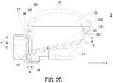
- FIG. 2Bis a schematic cross-sectional view illustrating the nebulizer of FIG. 2A and taken along the line AA.
- An example of the nebulizer 2includes but is not limited to a mesh nebulizer.
- the nebulizer 2is used for nebulizing liquid medicament into a plurality of tiny mist droplets.
- the mist dropletshave a diameter in the range between 1 micrometer and 5 micrometers. After these mist droplets are inhaled by the mouth of the patient, these mist droplets can reach bronchus and lungs of the patient for therapy and alleviation of the respiratory disease.
- the nebulizer 2comprises a medicament storage module 3, a nebulizing unit 4, and a conduit 5.
- the medicament storage module 3is used for containing and supplying liquid medicament.
- the nebulizing unit 4comprises a piezoelectric element 41 and a nozzle plate 42.
- the nebulizing unit 4is disposed on the medicament storage module 3.
- the conduit 5is detachably connected with the medicament storage module 3, and aligned with the nebulizing unit 4.
- the tiny mist droplets ejected from the nebulizing unit 4is guided to the mouth of the patient.
- FIG. 3Ais a schematic perspective view illustrating the medicament storage module of the nebulizer of FIG. 2A and 2B .
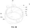
- FIG. 3Bis a schematic perspective view illustrating the medicament storage module of FIG. 3A and taken along another viewpoint.
- FIG. 3Cis a schematic top view illustrating the medicament storage module of FIG. 3A .
- FIG. 3Dis a schematic cross-sectional view illustrating the medicament storage module of FIG. 3A and taken along the line BB. Please refer to FIGS. 2A , 2B , 3A , 3B , 3C and 3D .
- the medicament storage module 3has a cup-shaped structure.
- the medicament storage module 3comprises an inclined bottom wall 31, a tubular sidewall 32, a storage chamber 33, an outlet 34, and a guiding part 35.
- the inclined bottom wall 31is inclined at an inclination angle ⁇ 1 with respect to a horizontal plane C.
- the inclination angle ⁇ 1is in the range between 3 and 30 degrees, and preferably in the range between 5 and 15 degrees.
- the tubular sidewall 32is connected with a periphery of the inclined bottom wall 31.
- the storage chamber 33has a top entrance 331 at a top side thereof.
- the storage chamber 33is defined by the inclined bottom wall 31 and the tubular sidewall 32.
- the storage chamber 33is used for accommodating or storing the liquid medicament.
- the tubular sidewall 32 and the inclined bottom wall 31are integrally formed with each other, and the tubular sidewall 32 is protruded upwardly from the periphery of the inclined bottom wall 31.
- the tubular sidewall 32is a circular sidewall. That is, the tubular sidewall 32 or the storage chamber 33 has a center axis Z. The center axis Z is perpendicular to the horizontal plane C. Moreover, there is an equidistance D between the center axis Z and the tubular sidewall 32.
- the thickness and the diameter of the inclined bottom wall 31 and the thickness and the height of the tubular sidewall 32may be varied according to the practical requirements.
- the guiding part 35 of the medicament storage module 3is located at a bottom surface 332 of the storage chamber 33, and arranged around the junction between the inclined bottom wall 31 and the tubular sidewall 32. In other words, the guiding part 35 is arranged around the periphery of the inner surface 332 of the inclined bottom wall 31 of the storage chamber 33.
- the guiding part 35is a C-shaped curvy structure, but is not limited thereto.
- the C-shaped curvy structure 35has a concave curvy surface 351.
- the radian of the curvy surface 351 of the C-shaped curvy structure 35is not restricted, and may be varied according to the practical requirements.
- the inclined bottom wall 31, the tubular sidewall 32 and the guiding part 35are integrally formed with each other.
- the outlet 34is formed in the tubular sidewall 32 of the medicament storage module 3. That is, the outlet 34 runs through the tubular sidewall 32.
- the liquid medicament within the storage chamber 33can be outputted or supplied through the outlet 34.
- the outlet 34has a first opening 341 and a second opening 342.
- the first opening 341is open to an inner surface 321 of the tubular sidewall 32 and aligned with a notch 352 of the guiding part 35.
- the second opening 342is open to an outer surface 322 of the tubular sidewall 32.
- the inclined bottom wall 31is extended downwardly to the outlet 34 and aligned with the nebulizing unit 4.
- the first opening 341 of the outlet 34is close to a lowest position 332a of the inner surface 332 of the inclined bottom wall 31 of the storage chamber 33 (see FIG. 3B ).
- the distance between the lowest position 332a of the inner surface 332 of the inclined bottom wall 31 of the storage chamber 33 and the horizontal plane Cis the shortest among all distances between the inner surface 332 of the inclined bottom wall 31 of the storage chamber 33 and the horizontal plane C.
- the both sides of the notch 352 of the guiding part 35have beveled edges 353 for facilitating guiding the liquid medicament to the outlet 34.
- the medicament storage module 3further comprises a coupling part 37.
- the coupling part 37is connected with the outer surface 322 of the tubular sidewall 32 and aligned with the second opening 342 of the outlet 34.
- the nozzle plate 42 of the nebulizing unit 4is aligned with the second opening 342 of the outlet 34.
- the coupling part 37 and the tubular sidewall 32are integrally formed with each other, and the coupling part 37 is extended externally from the outer surface 322 of the tubular sidewall 32 and aligned with the second opening 342 of the outlet 34.
- the coupling part 37comprises an extension wall 371 and a first recess 372.
- the first recess 372is defined by the extension wall 371 and the tubular sidewall 32 collaboratively. Moreover, the lateral surface of the first recess 372 has a multi-stepped structure mating with the piezoelectric element 41 and the nozzle plate 4 of the nebulizing unit 4, so that the nozzle plate 42 is aligned with the second opening 342 of the outlet 34.
- the conduit 5is detachably connected with the coupling part 37.
- the conduit 5comprises a coupling part 51, an entrance 52, and a tube part 53.
- the coupling part 51 of the conduit 5is coupled with the extension wall 371 of the coupling part 37, and fixed on the coupling part 37.
- the entrance 52 of the conduit 5is aligned with the nozzle plate 42 of the nebulizing unit 4. After the mist droplets are ejected from the nebulizing unit 4, the mist droplets are guided by the tube part 53 of the conduit 5.
- one or more waterproof gaskets 61e.g.
- ring-shaped rubbery gasketsare arranged between the nebulizing unit 4 and the outer surface 322 of the tubular sidewall 32 and between the nebulizing unit 4 and the coupling part 51 of the conduit 5 in order to prevent leakage of the liquid medicament.
- the medicament storage module 3further comprises an upper cover 36.
- the cover 36is pivotally coupled to the tubular sidewall 32 for sheltering the top entrance 331 of the storage chamber 33.
- the tubular sidewall 32further comprises at least one first shaft sleeve 323, and the cover 36 further comprises at least one second shaft sleeve 361.
- the medicament storage module 3further comprises at least one shaft lever 38. After the shaft lever 38 is penetrated through the first shaft sleeve 323 and the second shaft sleeve 361, the cover 36 is pivotally coupled to the tubular sidewall 32.
- the first shaft sleeve 323is integrally formed with the tubular sidewall 32, and located near a top edge 324 or the entrance 321 of the tubular sidewall 32, and located near the coupling part 37.
- the tubular sidewall 32further comprises at least one first engaging element 325
- the cover 36comprises at least one second engaging element 362 corresponding to the at least one first engaging element 325.
- the first engaging element 325is located near the top edge 324 or the entrance 321 of the tubular sidewall 32, and is opposed to the first shaft sleeve 323. Moreover, a second recess 326 is formed in the top edge 324 of the tubular sidewall 32.
- a waterproof gasket 62e.g. a ring-shaped rubbery gasket
- the cover 36further comprises one or more ventilation holes (not shown), but is not limited thereto.
- the nebulizing unit 4comprises the piezoelectric element 41 and the nozzle plate 42.
- the piezoelectric element 41is a vibrating element for driving vibration of the nozzle plate 42.
- the nozzle plate 42comprises a plurality of nozzles (not shown). As the nozzle plate 42 is vibrated by the piezoelectric element 41, the liquid medicament is nebulized into the tiny mist droplets to be ejected through the nozzles.
- the piezoelectric element 41 and the nozzle plate 4 of the nebulizing unit 4are disposed within the first recess 372 of the coupling part 37 of the medicament storage module 3. In addition, the nozzle plate 42 is aligned with the second opening 342 of the outlet 34.
- the liquid medicament outputted from the outlet 34can be nebulized into the tiny mist droplets by the nebulizing unit 4.
- the nozzle plate 42has a circular profile.
- the nozzles of the nozzle plate 42i.e. the effective action region
- the nebulizing efficiency of the nebulizer 2is enhanced.
- FIG. 4Ais a schematic perspective view illustrating a variant example of the medicament storage module of the nebulizer of the present invention, wherein the upper cover is not shown.
- FIG. 4Bis a schematic cross-sectional view illustrating the medicament storage module of FIG. 4A and taken along the line DD.
- the medicament storage module 3has a cup-shaped structure.
- the medicament storage module 3comprises an inclined bottom wall 31, a tubular sidewall 32, a storage chamber 33, an outlet 34, and a C-shaped curvy structure 35.
- the inclined bottom wall 31is inclined at an inclination angle ⁇ 1 with respect to a horizontal plane C.
- the inclination angle ⁇ 1is in the range between 3 and 30 degrees, and preferably in the range between 5 and 15 degrees.
- the storage chamber 33 with a top entrance 331 and the outlet 34is defined by the inclined bottom wall 31, the tubular sidewall 32 and the C-shaped curvy structure 33 collaboratively.
- the inclined bottom wall 31is extended downwardly to the outlet 34.
- the C-shaped curvy structure 35is connected with the inclined bottom wall 31 and tubular sidewall 32, and arranged around the periphery of the inner surface 332 of the inclined bottom wall 31 of the storage chamber 33.
- the nebulizer 2further comprises a handle (not shown), and the handle is detachably connected with the medicament storage module 3.
- a power source(not shown) may be disposed within the handle for providing electric power to associated components of the nebulizer 2.
- a control panel(not shown) may be disposed within the handle for controlling operations of the nebulizer 2.
- FIG. 5is a plot illustrating the relationship between the residual medicament percentage and the inclination angle of the inclined bottom wall of the medicament storage module of FIGS. 2A and 2B .
- the residual medicament percentageis 0.401%, 0.304%, 0.112%, 0.023%, 0.008%, 0.002% and 0.001%, respectively. That is, if the inclination angle ⁇ 1 of the inclined bottom wall 31 in the range between 3 and 30 degrees, the residual medicament percentage of the nebulizer 2 can be effectively reduced.
- the inclination angle ⁇ 1 of the inclined bottom wall 31in the range between 5 and 15 degrees, the overall height and size of the nebulizer 2 and the storage chamber 33 of the medicament storage module 3 can be reduced while complying with the required medicament capacity (e.g. 4 ⁇ 5ml). Consequently, the nebulizer 2 can be carried by the user more easily.
- the present inventionprovides a medicament storage module.
- a tubular sidewall and an inclined bottom wall with an inclination anglethe viscous liquid medicament can be easily guided to the outlet and outputted.
- a guiding parte.g. a C-shaped curvy structure
- no inside cornersare formed within the storage chamber of the medicament storage module. Consequently, there are no dead zones in the storage chamber, and the liquid medicament can be naturally guided to the outlet by the guiding part.
- the inclination angleis specially designed, the residual medicament percentage can be effectively reduced, and the overall height and size of the nebulizer and the storage chamber of the medicament storage module can be reduced while complying with the required medicament capacity (e.g. 4 ⁇ 5ml). Consequently, the nebulizer can be carried by the user more easily. In the subsequent use of the nebulizer, the problem of contaminating the medicament or causing bacteria growth will be avoided.
- the nebulizer of the preset inventioncan be used to administer medicament to treat or alleviate pain of the patient with a respiratory disease.
- the nebulizercan be used to administer medicament to be inhaled into the lungs of the patient in replace of oral administration.
- the nebulizercan be carried to immediately administer medicament and quickly generate the drug action to the patient with exacerbation of the obstructive respiratory tract.
- the use of the nebulizercan immediately cure or relieve the patient in the event of sudden onset.
Landscapes
- Health & Medical Sciences (AREA)
- Engineering & Computer Science (AREA)
- General Health & Medical Sciences (AREA)
- Public Health (AREA)
- Heart & Thoracic Surgery (AREA)
- Hematology (AREA)
- Life Sciences & Earth Sciences (AREA)
- Animal Behavior & Ethology (AREA)
- Anesthesiology (AREA)
- Biomedical Technology (AREA)
- Veterinary Medicine (AREA)
- Pulmonology (AREA)
- Bioinformatics & Cheminformatics (AREA)
- Special Spraying Apparatus (AREA)
- Medicinal Preparation (AREA)
- Emergency Medicine (AREA)
- Infusion, Injection, And Reservoir Apparatuses (AREA)
Description
- The present invention relates to a medicament storage module, and more particularly to a medicament storage module that has reduced residual medicament liquid and is easily cleaned.
- Recently, a nebulizer has been widely used for health care and beauty purposes. For example, the nebulizer may be used to administer medicament to treat or alleviate pain of the patient with a respiratory disease. In addition, the nebulizer may be used to administer medicament to be inhaled into the lungs of the patient in replace of oral administration. Consequently, the absorption efficiency and action efficiency of the medicament are enhanced and the occurrence of the side effect is reduced. Moreover, the nebulizer can be carried to immediately administer medicament and quickly generate the drug action to the patient with exacerbation of the obstructive respiratory tract. In other words, the use of the nebulizer can immediately cure or relieve the patient in the event of sudden onset.
- Generally, the nebulizer may be used to nebulize or vaporize the liquid medicament into mist droplets. After these mist droplets are inhaled by the mouth of the patient, these mist droplets can reach bronchus and lungs of the patient for therapy and alleviation of the respiratory disease. According to the nebulizing mechanism, the nebulizers are classified into several types, e.g. a pneumatic jet nebulizer, an ultrasonic nebulizer and a mesh nebulizer. The nebulizing mechanism of the mesh nebulizer for nebulizing liquid medicament into mist droplets comprises a piezoelectric element, a nozzle plate and a corresponding micro pump.
FIG. 1 is a schematic cross-sectional view illustrating a medicament cartridge of a conventional mesh nebulizer. As shown inFIG. 1 , themedicament cartridge 1 is substantially a rectangular hollow structure. Themedicament cartridge 1 comprises abottom wall 11, fourlateral walls 12, anaccommodation space 13, and anoutlet 14. Thebottom wall 11 is a rectangular plate. The fourlateral walls 12 are connected with each other and perpendicular to each other. Moreover, the fourlateral walls 12 are perpendicularly connected with the edges of thebottom wall 11. Theaccommodation space 13 is defined by thebottom wall 11 and the fourlateral walls 12 collaboratively. Theoutlet 14 runs through one of the fourlateral walls 12, and is located near thebottom wall 11. The liquid medicament within theaccommodation space 13 can be outputted or supplied through theoutlet 14.- In the
conventional medicament cartridge 1, thebottom wall 11 is in parallel with the horizontal plane, and the fourlateral walls 12 are perpendicularly connected with the edges of thebottom wall 11. Consequently, a plurality of inside corners are formed at the bottom of theaccommodation space 13. Due to the inside corners, a portion of the liquid medicament is usually retained at the bottom of theaccommodation space 13 after the nebulizing operation of the nebulizer is completed. In other words, theconventional medicament cartridge 1 may result in the problems of wasting medicament or supplying insufficient amount of medicament. Moreover, since the medicament contained in theaccommodation space 13 of themedicament cartridge 1 is viscous and the inside corners at the bottom of theaccommodation space 13 are dead zones of liquid flow, the medicament is readily retained at the regions of thebottom wall 11 far from theoutlet 14 and at the inside corners. Moreover, it is difficult to clean theconventional medicament cartridge 1. The subsequent use of themedicament cartridge 1 may contaminate the medicament or cause a bacteria problem. - Therefore, there is a need of providing a nebulizer and a medicament storage module in order to eliminate the above drawbacks.
US 2013 119 151 A relates to an aerosol generator assembly comprising a vibratable piezo ceramic body (2) having first and second opposing sides, an aperture defined in the vibratable body and extending through the body from the first side to the second side and having a layer of electrical contact material on each side of the vibratable body, the vibratable body being vibratable by application of an electrical signal thereto; a vibratable member (1) with pores defined therein, the vibratable member mounted across the aperture; and an electrical contact material free-zone (4) is provided on at least one side of the body about the aperture, characterised in that the electrical contact material free-zone and the vibratable member are dimensioned so that the vibratable member is mountable directly onto the vibratable body on top thereof within the electrical contact material free-zone such that a gap area free of electrode contact material is formed between the terminating edge of the electrical contact material and the periphery of the vibratable member.US 2007 267 010 A relates to a method of treating a patient with a pulmonary disease, where the method includes delivering a dose of aerosolized medicament intermittently to a ventilator circuit coupled to the respiratory system of the patient. Also, a method of treating a patient with a pulmonary disease, where the method includes taking the patient off a ventilator, and administering to the patient, a nebulized aerosol comprising from about 100 mug to about 500 mg of a medicament.; Also a method of treating a patient with a pulmonary disease, the method comprising administering an aerosolized first medicament comprising amikacin to the patient and administering, systemically a second medicament comprising an antibiotic to the patient that also treats the pulmonary disease, wherein a resulting amikacin concentration in the lung and/or pulmonary system is therapeutically-effective, and an amount of the systemically administered antibiotics is reduced.- The scope of the invention is as defined by the appended claims.
- The present invention provides a medicament storage module for solving the problems of wasting medicament or supplying insufficient medicament.
- The present invention provides a medicament storage module that is easily cleaned. In the subsequent use the problem of contaminating the medicament or causing bacteria growth will be avoided.
- In accordance with an example there is provided a nebulizer. The nebulizer includes a medicament storage module and a nebulizing unit. The medicament storage module includes an inclined bottom wall, a tubular sidewall, and a guiding part. The inclined bottom wall is inclined at an inclination angle with respect to a horizontal plane. The tubular sidewall is connected with a periphery of the inclined bottom wall. A storage chamber with a top entrance is defined by the inclined bottom wall and the tubular sidewall collaboratively, and a liquid medicament is accommodated within the storage chamber. The tubular sidewall has an outlet, and the inclined bottom wall is extended downwardly to the outlet. The guiding part is arranged around a junction between the inclined bottom wall and the tubular sidewall. The nebulizing unit is disposed on the medicament storage module and aligned with the outlet. The liquid medicament outputted from the outlet is nebulized into a plurality of mist droplets by the nebulizing unit.
- In accordance with the present invention, there is provided a medicament storage module. The medicament storage module includes an inclined bottom wall, a tubular sidewall, and a guiding part. The inclined bottom wall is inclined at an inclination angle with respect to a horizontal plane. The tubular sidewall is connected with a periphery of the inclined bottom wall. A storage chamber with a top entrance is defined by the inclined bottom wall and the tubular sidewall collaboratively, and a liquid medicament is accommodated within the storage chamber. The tubular sidewall has an outlet, and the inclined bottom wall is extended downwardly to the outlet. The guiding part is arranged around a junction between the inclined bottom wall and the tubular sidewall.
- In accordance with a further aspect of the present invention, there is provided a medicament storage module. The medicament storage module includes an inclined bottom wall, a tubular sidewall, and a C-shaped curvy structure. The inclined bottom wall is inclined at an inclination angle with respect to a horizontal plane. The C-shaped curvy structure is arranged around a junction between the inclined bottom wall and the tubular sidewall. A storage chamber with a top entrance and an outlet is defined by the inclined bottom wall, the tubular sidewall and the C-shaped curvy structure collaboratively. A liquid medicament is accommodated within the storage chamber. The inclined bottom wall is extended downwardly to the outlet.
- The above contents of the present invention will become more readily apparent to those ordinarily skilled in the art after reviewing the following detailed description and accompanying drawings, in which:
FIG. 1 is a schematic cross-sectional view illustrating a medicament cartridge of a conventional mesh nebulizer;FIG. 2A is a schematic side view illustrating a nebulizer.FIG 2B is a schematic cross-sectional view illustrating the nebulizer ofFIG 2A and taken along the line AA;FIG. 3A is a schematic perspective view illustrating the medicament storage module of the nebulizer ofFIG. 2A and2B ;FIG 3B is a schematic perspective view illustrating the medicament storage module ofFIG 3A and taken along another viewpoint;FIG. 3C is a schematic top view illustrating the medicament storage module ofFIG. 3A ;FIG 3D is a schematic cross-sectional view illustrating the medicament storage module ofFIG. 3A and taken along the line BB;FIG. 4A is a schematic perspective view illustrating a variant example of the medicament storage module of the nebulizer wherein the upper cover is not shown;FIG 4B is a schematic cross-sectional view illustrating the medicament storage module ofFIG. 4A and taken along the line DD; andFIG. 5 is a plot illustrating the relationship between the residual medicament percentage and the inclination angle of the inclined bottom wall of the medicament storage module ofFIGS. 2A and2B .- The present invention will now be described more specifically with reference to the following embodiments. It is to be noted that the following descriptions of preferred embodiments of this invention are presented herein for purpose of illustration and description only. It is not intended to be exhaustive or to be limited to the precise form disclosed.
FIG. 2A is a schematic side view illustrating a nebulizer.FIG. 2B is a schematic cross-sectional view illustrating the nebulizer ofFIG. 2A and taken along the line AA. An example of thenebulizer 2 includes but is not limited to a mesh nebulizer. Thenebulizer 2 is used for nebulizing liquid medicament into a plurality of tiny mist droplets. For example, the mist droplets have a diameter in the range between 1 micrometer and 5 micrometers. After these mist droplets are inhaled by the mouth of the patient, these mist droplets can reach bronchus and lungs of the patient for therapy and alleviation of the respiratory disease.- In this example the
nebulizer 2 comprises amedicament storage module 3, anebulizing unit 4, and aconduit 5. Themedicament storage module 3 is used for containing and supplying liquid medicament. Thenebulizing unit 4 comprises apiezoelectric element 41 and anozzle plate 42. Thenebulizing unit 4 is disposed on themedicament storage module 3. By thenebulizing unit 4, the liquid medicament from themedicament storage module 3 is nebulized into the tiny mist droplets to be ejected. Theconduit 5 is detachably connected with themedicament storage module 3, and aligned with thenebulizing unit 4. By theconduit 5, the tiny mist droplets ejected from thenebulizing unit 4 is guided to the mouth of the patient. FIG. 3A is a schematic perspective view illustrating the medicament storage module of the nebulizer ofFIG. 2A and2B .FIG. 3B is a schematic perspective view illustrating the medicament storage module ofFIG. 3A and taken along another viewpoint.FIG. 3C is a schematic top view illustrating the medicament storage module ofFIG. 3A .FIG. 3D is a schematic cross-sectional view illustrating the medicament storage module ofFIG. 3A and taken along the line BB. Please refer toFIGS. 2A ,2B ,3A ,3B ,3C and3D . Themedicament storage module 3 has a cup-shaped structure. In addition, themedicament storage module 3 comprises aninclined bottom wall 31, atubular sidewall 32, astorage chamber 33, anoutlet 34, and a guidingpart 35. Theinclined bottom wall 31 is inclined at an inclination angle θ1 with respect to a horizontal plane C. The inclination angle θ1 is in the range between 3 and 30 degrees, and preferably in the range between 5 and 15 degrees. Thetubular sidewall 32 is connected with a periphery of theinclined bottom wall 31. Moreover, thestorage chamber 33 has atop entrance 331 at a top side thereof. Thestorage chamber 33 is defined by theinclined bottom wall 31 and thetubular sidewall 32. Thestorage chamber 33 is used for accommodating or storing the liquid medicament. In an embodiment, thetubular sidewall 32 and theinclined bottom wall 31 are integrally formed with each other, and thetubular sidewall 32 is protruded upwardly from the periphery of theinclined bottom wall 31. Preferably, thetubular sidewall 32 is a circular sidewall. That is, thetubular sidewall 32 or thestorage chamber 33 has a center axis Z. The center axis Z is perpendicular to the horizontal plane C. Moreover, there is an equidistance D between the center axis Z and thetubular sidewall 32. In this embodiment, the thickness and the diameter of theinclined bottom wall 31 and the thickness and the height of thetubular sidewall 32 may be varied according to the practical requirements.- The guiding
part 35 of themedicament storage module 3 is located at abottom surface 332 of thestorage chamber 33, and arranged around the junction between theinclined bottom wall 31 and thetubular sidewall 32. In other words, the guidingpart 35 is arranged around the periphery of theinner surface 332 of theinclined bottom wall 31 of thestorage chamber 33. By means of the guidingpart 35, no inside corners are formed within thestorage chamber 33 of themedicament storage module 3. Consequently, the possibility of retaining the liquid medicament in thestorage chamber 33 can be reduced, and thestorage chamber 33 can be easily cleaned. In this embodiment, the guidingpart 35 is a C-shaped curvy structure, but is not limited thereto. Preferably, the C-shapedcurvy structure 35 has a concavecurvy surface 351. Moreover, the radian of thecurvy surface 351 of the C-shapedcurvy structure 35 is not restricted, and may be varied according to the practical requirements. In some embodiments, theinclined bottom wall 31, thetubular sidewall 32 and the guidingpart 35 are integrally formed with each other. - The
outlet 34 is formed in thetubular sidewall 32 of themedicament storage module 3. That is, theoutlet 34 runs through thetubular sidewall 32. The liquid medicament within thestorage chamber 33 can be outputted or supplied through theoutlet 34. Theoutlet 34 has afirst opening 341 and asecond opening 342. Thefirst opening 341 is open to aninner surface 321 of thetubular sidewall 32 and aligned with anotch 352 of the guidingpart 35. Thesecond opening 342 is open to anouter surface 322 of thetubular sidewall 32. In this embodiment, theinclined bottom wall 31 is extended downwardly to theoutlet 34 and aligned with thenebulizing unit 4. Thefirst opening 341 of theoutlet 34 is close to alowest position 332a of theinner surface 332 of theinclined bottom wall 31 of the storage chamber 33 (seeFIG. 3B ). The distance between thelowest position 332a of theinner surface 332 of theinclined bottom wall 31 of thestorage chamber 33 and the horizontal plane C is the shortest among all distances between theinner surface 332 of theinclined bottom wall 31 of thestorage chamber 33 and the horizontal plane C. In an embodiment, the both sides of thenotch 352 of the guidingpart 35 have bevelededges 353 for facilitating guiding the liquid medicament to theoutlet 34. - The
medicament storage module 3 further comprises acoupling part 37. Thecoupling part 37 is connected with theouter surface 322 of thetubular sidewall 32 and aligned with thesecond opening 342 of theoutlet 34. After thenebulizing unit 4 is installed in thecoupling part 37, thenozzle plate 42 of thenebulizing unit 4 is aligned with thesecond opening 342 of theoutlet 34. In an embodiment, thecoupling part 37 and thetubular sidewall 32 are integrally formed with each other, and thecoupling part 37 is extended externally from theouter surface 322 of thetubular sidewall 32 and aligned with thesecond opening 342 of theoutlet 34. Thecoupling part 37 comprises anextension wall 371 and afirst recess 372. Thefirst recess 372 is defined by theextension wall 371 and thetubular sidewall 32 collaboratively. Moreover, the lateral surface of thefirst recess 372 has a multi-stepped structure mating with thepiezoelectric element 41 and thenozzle plate 4 of thenebulizing unit 4, so that thenozzle plate 42 is aligned with thesecond opening 342 of theoutlet 34. - The
conduit 5 is detachably connected with thecoupling part 37. In this embodiment, theconduit 5 comprises acoupling part 51, anentrance 52, and atube part 53. Thecoupling part 51 of theconduit 5 is coupled with theextension wall 371 of thecoupling part 37, and fixed on thecoupling part 37. Theentrance 52 of theconduit 5 is aligned with thenozzle plate 42 of thenebulizing unit 4. After the mist droplets are ejected from thenebulizing unit 4, the mist droplets are guided by thetube part 53 of theconduit 5. In some embodiments, one or more waterproof gaskets 61 (e.g. ring-shaped rubbery gaskets) are arranged between thenebulizing unit 4 and theouter surface 322 of thetubular sidewall 32 and between thenebulizing unit 4 and thecoupling part 51 of theconduit 5 in order to prevent leakage of the liquid medicament. - The
medicament storage module 3 further comprises anupper cover 36. Thecover 36 is pivotally coupled to thetubular sidewall 32 for sheltering thetop entrance 331 of thestorage chamber 33. Thetubular sidewall 32 further comprises at least onefirst shaft sleeve 323, and thecover 36 further comprises at least onesecond shaft sleeve 361. Themedicament storage module 3 further comprises at least oneshaft lever 38. After theshaft lever 38 is penetrated through thefirst shaft sleeve 323 and thesecond shaft sleeve 361, thecover 36 is pivotally coupled to thetubular sidewall 32. In a preferred embodiment, thefirst shaft sleeve 323 is integrally formed with thetubular sidewall 32, and located near atop edge 324 or theentrance 321 of thetubular sidewall 32, and located near thecoupling part 37. Moreover, thetubular sidewall 32 further comprises at least one firstengaging element 325, and thecover 36 comprises at least one secondengaging element 362 corresponding to the at least one firstengaging element 325. After thecover 36 is rotated to the position over thetop entrance 331 of thestorage chamber 33, the firstengaging element 325 of thetubular sidewall 32 and the secondengaging element 362 of thecover 36 are engaged with each other. Consequently, thetop entrance 331 of thestorage chamber 33 is tightly sealed by thecover 36. In an embodiment, the firstengaging element 325 is located near thetop edge 324 or theentrance 321 of thetubular sidewall 32, and is opposed to thefirst shaft sleeve 323. Moreover, asecond recess 326 is formed in thetop edge 324 of thetubular sidewall 32. A waterproof gasket 62 (e.g. a ring-shaped rubbery gasket) is accommodated within thesecond recess 326 in order to prevent leakage of the liquid medicament. In some other embodiments, thecover 36 further comprises one or more ventilation holes (not shown), but is not limited thereto. - The
nebulizing unit 4 comprises thepiezoelectric element 41 and thenozzle plate 42. Thepiezoelectric element 41 is a vibrating element for driving vibration of thenozzle plate 42. Thenozzle plate 42 comprises a plurality of nozzles (not shown). As thenozzle plate 42 is vibrated by thepiezoelectric element 41, the liquid medicament is nebulized into the tiny mist droplets to be ejected through the nozzles. Thepiezoelectric element 41 and thenozzle plate 4 of thenebulizing unit 4 are disposed within thefirst recess 372 of thecoupling part 37 of themedicament storage module 3. In addition, thenozzle plate 42 is aligned with thesecond opening 342 of theoutlet 34. Consequently, the liquid medicament outputted from theoutlet 34 can be nebulized into the tiny mist droplets by thenebulizing unit 4. In an example thenozzle plate 42 has a circular profile. In particular, the nozzles of the nozzle plate 42 (i.e. the effective action region) are directly aligned with thesecond opening 342 of theoutlet 34. Consequently, the nebulizing efficiency of thenebulizer 2 is enhanced. FIG. 4A is a schematic perspective view illustrating a variant example of the medicament storage module of the nebulizer of the present invention, wherein the upper cover is not shown.FIG. 4B is a schematic cross-sectional view illustrating the medicament storage module ofFIG. 4A and taken along the line DD. As shown inFIGS. 4A and4B , themedicament storage module 3 has a cup-shaped structure. In addition, themedicament storage module 3 comprises aninclined bottom wall 31, atubular sidewall 32, astorage chamber 33, anoutlet 34, and a C-shapedcurvy structure 35. Theinclined bottom wall 31 is inclined at an inclination angle θ1 with respect to a horizontal plane C. The inclination angle θ1 is in the range between 3 and 30 degrees, and preferably in the range between 5 and 15 degrees. Thestorage chamber 33 with atop entrance 331 and theoutlet 34 is defined by theinclined bottom wall 31, thetubular sidewall 32 and the C-shapedcurvy structure 33 collaboratively. Theinclined bottom wall 31 is extended downwardly to theoutlet 34. The C-shapedcurvy structure 35 is connected with theinclined bottom wall 31 andtubular sidewall 32, and arranged around the periphery of theinner surface 332 of theinclined bottom wall 31 of thestorage chamber 33. By means of the guidingpart 35, no inside corners are formed within thestorage chamber 33 of themedicament storage module 3. Consequently, the possibility of retaining the liquid medicament in thestorage chamber 33 can be reduced, and thestorage chamber 33 can be easily cleaned. The structures and functions of theinclined bottom wall 31, thetubular sidewall 32, thestorage chamber 33, theoutlet 34 and the C-shapedcurvy structure 35 of this embodiment are similar to those illustrated inFIGS. 3A ,3B ,3C and3D , and are not redundantly described herein.- In some examples the
nebulizer 2 further comprises a handle (not shown), and the handle is detachably connected with themedicament storage module 3. Moreover, a power source (not shown) may be disposed within the handle for providing electric power to associated components of thenebulizer 2. Moreover, a control panel (not shown) may be disposed within the handle for controlling operations of thenebulizer 2. FIG. 5 is a plot illustrating the relationship between the residual medicament percentage and the inclination angle of the inclined bottom wall of the medicament storage module ofFIGS. 2A and2B . In case that the inclination angle θ1 of theinclined bottom wall 31 of themedicament storage module 3 is 3, 5, 7, 10, 12, 15 and 30 degrees, the residual medicament percentage is 0.401%, 0.304%, 0.112%, 0.023%, 0.008%, 0.002% and 0.001%, respectively. That is, if the inclination angle θ1 of theinclined bottom wall 31 in the range between 3 and 30 degrees, the residual medicament percentage of thenebulizer 2 can be effectively reduced. Especially, if the inclination angle θ1 of theinclined bottom wall 31 in the range between 5 and 15 degrees, the overall height and size of thenebulizer 2 and thestorage chamber 33 of themedicament storage module 3 can be reduced while complying with the required medicament capacity (e.g. 4∼5ml). Consequently, thenebulizer 2 can be carried by the user more easily.- From the above descriptions, the present invention provides a medicament storage module. By means of a tubular sidewall and an inclined bottom wall with an inclination angle, the viscous liquid medicament can be easily guided to the outlet and outputted. By means of a guiding part (e.g. a C-shaped curvy structure) of the medicament storage module, no inside corners are formed within the storage chamber of the medicament storage module. Consequently, there are no dead zones in the storage chamber, and the liquid medicament can be naturally guided to the outlet by the guiding part. After the nebulizing operation of the nebulizer is completed, the residual medicament is reduced, and the problems of wasting medicament or supplying insufficient medicament can be overcome. Moreover, since the inclination angle is specially designed, the residual medicament percentage can be effectively reduced, and the overall height and size of the nebulizer and the storage chamber of the medicament storage module can be reduced while complying with the required medicament capacity (e.g. 4∼5ml). Consequently, the nebulizer can be carried by the user more easily. In the subsequent use of the nebulizer, the problem of contaminating the medicament or causing bacteria growth will be avoided. Moreover, the nebulizer of the preset invention can be used to administer medicament to treat or alleviate pain of the patient with a respiratory disease. In addition, the nebulizer can be used to administer medicament to be inhaled into the lungs of the patient in replace of oral administration. Consequently, the absorption efficiency and action efficiency of the medicament are enhanced and the occurrence of the side effect is reduced. Moreover, the nebulizer can be carried to immediately administer medicament and quickly generate the drug action to the patient with exacerbation of the obstructive respiratory tract. In other words, the use of the nebulizer can immediately cure or relieve the patient in the event of sudden onset.
Claims (12)
- A medicament storage module (3) for nebulizers,
comprising:an inclined bottom wall (31) disposed in the bottom and inclined at an inclination angle (θ1) with respect to a horizontal plane (C);a tubular sidewall (32) preferably connected with a periphery of the inclined bottom wall (31); anda guiding part (35) arranged around a junction between the inclined bottom wall (31) and the tubular sidewall (32);characterized in that a storage chamber (33) with a top entrance (331) is defined by the inclined bottom wall (31) and the tubular sidewall (32) collaboratively, and a liquid medicament is accommodated within the storage chamber (33), wherein the tubular sidewall (32) has an outlet (34), the inclined bottom wall (31) is extended downwardly to the outlet (34), and the storage chamber (33) has a center axis Z, which is perpendicular to the horizontal plane C, and the top entrance (331) and the outlet (34) are axially perpendicular to each other, and the outlet (34) has a first opening (341) and a second opening (342), wherein the first opening (341) is open to an inner surface (321) of the tubular sidewall (32) and aligned with a notch (352) of the guiding part (35), and the second opening (342) is open to an outer surface (322) of the tubular sidewall (32). - The medicament storage module according to claim 1, wherein the inclination angle (θ1) is in a range between 3 and 30 degrees.
- The medicament storage module according to claim 1, wherein the inclination angle (θ1) is in a range between 5 and 15 degrees.
- The medicament storage module according to claim 1, wherein both sides of the notch (352) of the guiding part (35) have beveled edges (353).
- The medicament storage module according to claim 1, wherein the guiding part (35) is a C-shaped curvy structure (35), the C-shaped curvy structure (35) is connected with the inclined bottom wall (31) and tubular sidewall (32), and arranged around the periphery of a inner surface (332) of the inclined bottom wall (31).
- The medicament storage module according to claim 1, wherein the outlet (34) is adjacent to a lowest position (332a) of inner surface (332) of the inclined bottom wall (31).
- The medicament storage module according to claim 1, wherein the medicament storage module (3) further comprises a cover (36), wherein the cover (36) is pivotally coupled to the tubular sidewall (32) for sheltering the top entrance (331) of the storage chamber (33).
- The medicament storage module according to claim 7, wherein the tubular sidewall (32) further comprises at least one first engaging element (325), and the cover (36) comprises at least one second engaging element (362) corresponding to the at least one first engaging element (325), when the cover is closed, the at least one first engaging element (325) and the at least one second engaging element (362) are engaged with each other.
- The medicament storage module according to claim 1, wherein a nebulizing unit (4) is disposed on the medicament storage module (3) and aligned with the outlet (34), wherein in use the liquid medicament outputted from the outlet (34) is nebulized into a plurality of mist droplets by the nebulizing unit (4), wherein the medicament storage module (3) further comprises a coupling part (37), and the coupling part (37) is connected with an outer surface (322) of the tubular sidewall (32) and aligned with the outlet (34), wherein the coupling part (37) comprises an extension wall (371) and a first recess (372), and the nebulizing unit (4) is disposed within the first recess (372).
- The medicament storage module to claim 9, further comprising a conduit (5), wherein the conduit (5) is detachably connected with the coupling part (37) of the medicament storage module (3).
- The medicament storage module to claim 1, wherein a second recess (326) is formed in a top edge (324) of the tubular sidewall (32), and a waterproof gasket (62) is accommodated within the second recess (326).
- The medicament storage module to claim 1, wherein the nebulizing unit (4) is disposed on the medicament storage module (3) and aligned with the outlet (34), wherein in use the liquid medicament outputted from the outlet (34) is nebulized into a plurality of mist droplets by the nebulizing unit (4), wherein the nebulizing unit (4) comprises a piezoelectric element (41) and a nozzle plate (42).
Applications Claiming Priority (1)
| Application Number | Priority Date | Filing Date | Title |
|---|---|---|---|
| TW102133093ATWI539978B (en) | 2013-09-13 | 2013-09-13 | Nebulizer and medicament storage module thereof |
Publications (2)
| Publication Number | Publication Date |
|---|---|
| EP2848274A1 EP2848274A1 (en) | 2015-03-18 |
| EP2848274B1true EP2848274B1 (en) | 2016-12-21 |
Family
ID=50028848
Family Applications (1)
| Application Number | Title | Priority Date | Filing Date |
|---|---|---|---|
| EP14153122.8AActiveEP2848274B1 (en) | 2013-09-13 | 2014-01-29 | Medicament storage module |
Country Status (3)
| Country | Link |
|---|---|
| US (1) | US20150075521A1 (en) |
| EP (1) | EP2848274B1 (en) |
| TW (1) | TWI539978B (en) |
Families Citing this family (16)
| Publication number | Priority date | Publication date | Assignee | Title |
|---|---|---|---|---|
| IL298116A (en) | 2010-12-22 | 2023-01-01 | Syqe Medical Ltd | Method and system for drug delivery |
| US11298477B2 (en) | 2014-06-30 | 2022-04-12 | Syqe Medical Ltd. | Methods, devices and systems for pulmonary delivery of active agents |
| IL273507B2 (en) | 2014-06-30 | 2024-06-01 | Syqe Medical Ltd | Methods, devices and systems for administering active substances through the lungs |
| RU2721064C2 (en) | 2014-06-30 | 2020-05-15 | Сике Медикал Лтд. | Flow-controlled inhaler |
| WO2016001924A2 (en) | 2014-06-30 | 2016-01-07 | Syqe Medical Ltd. | Methods, devices and systems for pulmonary delivery of active agents |
| AU2015283589B2 (en) | 2014-06-30 | 2019-09-12 | Syqe Medical Ltd. | Method and device for vaporization and inhalation of isolated substances |
| CN106659858B (en)* | 2014-06-30 | 2020-11-24 | Syqe医药有限公司 | Medication dose box for inhaler device |
| TWD168862S (en)* | 2014-11-21 | 2015-07-01 | 台達電子工業股份有限公司 | Spray can part |
| EP3103497B1 (en)* | 2015-06-11 | 2019-04-24 | Delta Electronics, Inc. | Nebulizing device and nebulizer |
| CA3009599A1 (en) | 2016-01-06 | 2017-07-13 | Syqe Medical Ltd. | Low dose therapeutic treatment |
| TWI598152B (en)* | 2016-09-02 | 2017-09-11 | 心誠鎂行動醫電股份有限公司 | Cleaning method of atomizing device, and atomizing device having the same |
| JP6776761B2 (en)* | 2016-09-20 | 2020-10-28 | オムロンヘルスケア株式会社 | Mesh nebulizer and chemical pack |
| CN107670155A (en)* | 2017-11-10 | 2018-02-09 | 英路维(宁波)健康科技有限公司 | A kind of portable atomization respirometer |
| US11173258B2 (en) | 2018-08-30 | 2021-11-16 | Analog Devices, Inc. | Using piezoelectric electrodes as active surfaces for electroplating process |
| CN109157721B (en)* | 2018-10-12 | 2022-03-18 | 王亚伟 | Automatic accurate quantitative spraying device of position anesthesia for department of anesthesia |
| PL3756713T3 (en)* | 2018-12-19 | 2022-11-21 | Feellife Health Inc. | Atomization device having dual modules |
Family Cites Families (9)
| Publication number | Priority date | Publication date | Assignee | Title |
|---|---|---|---|---|
| US2028798A (en)* | 1933-11-07 | 1936-01-28 | American Can Co | Method of lining the inside of cans |
| US4592349A (en)* | 1981-08-10 | 1986-06-03 | Bird F M | Ventilator having an oscillatory inspiratory phase and method |
| US7971588B2 (en)* | 2000-05-05 | 2011-07-05 | Novartis Ag | Methods and systems for operating an aerosol generator |
| US8336545B2 (en)* | 2000-05-05 | 2012-12-25 | Novartis Pharma Ag | Methods and systems for operating an aerosol generator |
| DE10257381B4 (en)* | 2002-12-09 | 2006-09-14 | Pari GmbH Spezialisten für effektive Inhalation | Inhalation therapy device |
| DE102005006375B4 (en)* | 2005-02-11 | 2007-10-11 | Pari GmbH Spezialisten für effektive Inhalation | Aerosol generating device for inhalation therapy devices |
| DE102006030833A1 (en)* | 2006-07-04 | 2008-01-10 | Pari GmbH Spezialisten für effektive Inhalation | Method and device for cleaning the nebuliser membrane in an inhalation therapy device |
| DE102008022987A1 (en)* | 2008-05-09 | 2009-11-12 | Pari Pharma Gmbh | Nebulizer for respirators and ventilator with such a nebulizer |
| AU2011252026B2 (en)* | 2010-05-13 | 2015-09-03 | Nortev Limited | Aerosol generator assembly |
- 2013
- 2013-09-13TWTW102133093Apatent/TWI539978B/enactive
- 2013-12-30USUS14/144,181patent/US20150075521A1/ennot_activeAbandoned
- 2014
- 2014-01-29EPEP14153122.8Apatent/EP2848274B1/enactiveActive
Non-Patent Citations (1)
| Title |
|---|
| None* |
Also Published As
| Publication number | Publication date |
|---|---|
| TWI539978B (en) | 2016-07-01 |
| TW201509445A (en) | 2015-03-16 |
| US20150075521A1 (en) | 2015-03-19 |
| EP2848274A1 (en) | 2015-03-18 |
Similar Documents
| Publication | Publication Date | Title |
|---|---|---|
| EP2848274B1 (en) | Medicament storage module | |
| JP4589862B2 (en) | Nebulizer for inhalation | |
| EP3183021B1 (en) | Fluid reservoir for an aerosol generator and aerosol generator comprising the fluid reservoir | |
| EP3586976B1 (en) | Aerosol generator and aerosol delivery device comprising the aerosol generator | |
| EP2643038B1 (en) | Aerosol generator | |
| ES2533479T3 (en) | Nebulizer for respirators and respirator with a similar nebulizer | |
| US9937302B2 (en) | Nebulizing device and nebulizer | |
| US20110303218A1 (en) | Nasal nebulizer | |
| EP3777938A1 (en) | Aerosol generator | |
| EP2895136B1 (en) | Opening element for opening an ampoule in an aerosol generation device and aerosol generation device comprising the opening element | |
| EP3666315A1 (en) | Aerosol delivery device and method of operating the aerosol delivery device | |
| US9962504B2 (en) | Portable ultrasonic nebulizer and protection structure thereof | |
| TWM536948U (en) | Nebulizing device and nebulizer | |
| WO2019218428A1 (en) | Integrated sealed micro-mesh nebulizing module | |
| JP7030771B2 (en) | Aerosolization device and aerosol drug delivery device | |
| CN104436384B (en) | Micro-atomization device and dosing chamber module thereof | |
| EP2868339A1 (en) | An aerosol delivery system | |
| EP3103497B1 (en) | Nebulizing device and nebulizer | |
| US20080122903A1 (en) | Nebulizer and cartridge structure thereof | |
| WO2018185694A1 (en) | Device for the administration of substances | |
| TWM544940U (en) | Atomizer having adapted medicine cup | |
| WO2018072665A1 (en) | Multi-cavity atomizing apparatus | |
| ITBO20090132A1 (en) | DEVICE FOR NEBULIZATION OF SUBSTANCES IN A VENTILATION CIRCUIT | |
| KR102802564B1 (en) | Atomized liquid substance inhaler based on iot and control method using the same | |
| KR20080001029U (en) | Cartridge structure of sprayer and sprayer |
Legal Events
| Date | Code | Title | Description |
|---|---|---|---|
| PUAI | Public reference made under article 153(3) epc to a published international application that has entered the european phase | Free format text:ORIGINAL CODE: 0009012 | |
| 17P | Request for examination filed | Effective date:20140129 | |
| AK | Designated contracting states | Kind code of ref document:A1 Designated state(s):AL AT BE BG CH CY CZ DE DK EE ES FI FR GB GR HR HU IE IS IT LI LT LU LV MC MK MT NL NO PL PT RO RS SE SI SK SM TR | |
| AX | Request for extension of the european patent | Extension state:BA ME | |
| RIC1 | Information provided on ipc code assigned before grant | Ipc:A61M 15/00 20060101ALI20160511BHEP Ipc:A61M 11/00 20060101AFI20160511BHEP | |
| GRAP | Despatch of communication of intention to grant a patent | Free format text:ORIGINAL CODE: EPIDOSNIGR1 | |
| INTG | Intention to grant announced | Effective date:20160706 | |
| RIN1 | Information on inventor provided before grant (corrected) | Inventor name:LEE, KUO-LIANG Inventor name:LEE, YU-WEI | |
| GRAS | Grant fee paid | Free format text:ORIGINAL CODE: EPIDOSNIGR3 | |
| GRAA | (expected) grant | Free format text:ORIGINAL CODE: 0009210 | |
| AK | Designated contracting states | Kind code of ref document:B1 Designated state(s):AL AT BE BG CH CY CZ DE DK EE ES FI FR GB GR HR HU IE IS IT LI LT LU LV MC MK MT NL NO PL PT RO RS SE SI SK SM TR | |
| REG | Reference to a national code | Ref country code:GB Ref legal event code:FG4D | |
| REG | Reference to a national code | Ref country code:CH Ref legal event code:EP | |
| REG | Reference to a national code | Ref country code:IE Ref legal event code:FG4D | |
| REG | Reference to a national code | Ref country code:AT Ref legal event code:REF Ref document number:854944 Country of ref document:AT Kind code of ref document:T Effective date:20170115 | |
| REG | Reference to a national code | Ref country code:FR Ref legal event code:PLFP Year of fee payment:4 | |
| REG | Reference to a national code | Ref country code:DE Ref legal event code:R096 Ref document number:602014005559 Country of ref document:DE | |
| REG | Reference to a national code | Ref country code:NL Ref legal event code:FP | |
| PG25 | Lapsed in a contracting state [announced via postgrant information from national office to epo] | Ref country code:LV Free format text:LAPSE BECAUSE OF FAILURE TO SUBMIT A TRANSLATION OF THE DESCRIPTION OR TO PAY THE FEE WITHIN THE PRESCRIBED TIME-LIMIT Effective date:20161221 | |
| REG | Reference to a national code | Ref country code:LT Ref legal event code:MG4D | |
| PG25 | Lapsed in a contracting state [announced via postgrant information from national office to epo] | Ref country code:NO Free format text:LAPSE BECAUSE OF FAILURE TO SUBMIT A TRANSLATION OF THE DESCRIPTION OR TO PAY THE FEE WITHIN THE PRESCRIBED TIME-LIMIT Effective date:20170321 Ref country code:LT Free format text:LAPSE BECAUSE OF FAILURE TO SUBMIT A TRANSLATION OF THE DESCRIPTION OR TO PAY THE FEE WITHIN THE PRESCRIBED TIME-LIMIT Effective date:20161221 Ref country code:SE Free format text:LAPSE BECAUSE OF FAILURE TO SUBMIT A TRANSLATION OF THE DESCRIPTION OR TO PAY THE FEE WITHIN THE PRESCRIBED TIME-LIMIT Effective date:20161221 | |
| REG | Reference to a national code | Ref country code:AT Ref legal event code:MK05 Ref document number:854944 Country of ref document:AT Kind code of ref document:T Effective date:20161221 | |
| PG25 | Lapsed in a contracting state [announced via postgrant information from national office to epo] | Ref country code:HR Free format text:LAPSE BECAUSE OF FAILURE TO SUBMIT A TRANSLATION OF THE DESCRIPTION OR TO PAY THE FEE WITHIN THE PRESCRIBED TIME-LIMIT Effective date:20161221 Ref country code:FI Free format text:LAPSE BECAUSE OF FAILURE TO SUBMIT A TRANSLATION OF THE DESCRIPTION OR TO PAY THE FEE WITHIN THE PRESCRIBED TIME-LIMIT Effective date:20161221 Ref country code:RS Free format text:LAPSE BECAUSE OF FAILURE TO SUBMIT A TRANSLATION OF THE DESCRIPTION OR TO PAY THE FEE WITHIN THE PRESCRIBED TIME-LIMIT Effective date:20161221 Ref country code:BE Free format text:LAPSE BECAUSE OF NON-PAYMENT OF DUE FEES Effective date:20170131 | |
| PG25 | Lapsed in a contracting state [announced via postgrant information from national office to epo] | Ref country code:EE Free format text:LAPSE BECAUSE OF FAILURE TO SUBMIT A TRANSLATION OF THE DESCRIPTION OR TO PAY THE FEE WITHIN THE PRESCRIBED TIME-LIMIT Effective date:20161221 Ref country code:CZ Free format text:LAPSE BECAUSE OF FAILURE TO SUBMIT A TRANSLATION OF THE DESCRIPTION OR TO PAY THE FEE WITHIN THE PRESCRIBED TIME-LIMIT Effective date:20161221 Ref country code:IS Free format text:LAPSE BECAUSE OF FAILURE TO SUBMIT A TRANSLATION OF THE DESCRIPTION OR TO PAY THE FEE WITHIN THE PRESCRIBED TIME-LIMIT Effective date:20170421 Ref country code:SK Free format text:LAPSE BECAUSE OF FAILURE TO SUBMIT A TRANSLATION OF THE DESCRIPTION OR TO PAY THE FEE WITHIN THE PRESCRIBED TIME-LIMIT Effective date:20161221 Ref country code:RO Free format text:LAPSE BECAUSE OF FAILURE TO SUBMIT A TRANSLATION OF THE DESCRIPTION OR TO PAY THE FEE WITHIN THE PRESCRIBED TIME-LIMIT Effective date:20161221 | |
| PG25 | Lapsed in a contracting state [announced via postgrant information from national office to epo] | Ref country code:SM Free format text:LAPSE BECAUSE OF FAILURE TO SUBMIT A TRANSLATION OF THE DESCRIPTION OR TO PAY THE FEE WITHIN THE PRESCRIBED TIME-LIMIT Effective date:20161221 Ref country code:AT Free format text:LAPSE BECAUSE OF FAILURE TO SUBMIT A TRANSLATION OF THE DESCRIPTION OR TO PAY THE FEE WITHIN THE PRESCRIBED TIME-LIMIT Effective date:20161221 Ref country code:ES Free format text:LAPSE BECAUSE OF FAILURE TO SUBMIT A TRANSLATION OF THE DESCRIPTION OR TO PAY THE FEE WITHIN THE PRESCRIBED TIME-LIMIT Effective date:20161221 Ref country code:BG Free format text:LAPSE BECAUSE OF FAILURE TO SUBMIT A TRANSLATION OF THE DESCRIPTION OR TO PAY THE FEE WITHIN THE PRESCRIBED TIME-LIMIT Effective date:20170321 Ref country code:PL Free format text:LAPSE BECAUSE OF FAILURE TO SUBMIT A TRANSLATION OF THE DESCRIPTION OR TO PAY THE FEE WITHIN THE PRESCRIBED TIME-LIMIT Effective date:20161221 Ref country code:BE Free format text:LAPSE BECAUSE OF FAILURE TO SUBMIT A TRANSLATION OF THE DESCRIPTION OR TO PAY THE FEE WITHIN THE PRESCRIBED TIME-LIMIT Effective date:20161221 Ref country code:PT Free format text:LAPSE BECAUSE OF FAILURE TO SUBMIT A TRANSLATION OF THE DESCRIPTION OR TO PAY THE FEE WITHIN THE PRESCRIBED TIME-LIMIT Effective date:20170421 | |
| REG | Reference to a national code | Ref country code:DE Ref legal event code:R097 Ref document number:602014005559 Country of ref document:DE | |
| PG25 | Lapsed in a contracting state [announced via postgrant information from national office to epo] | Ref country code:MC Free format text:LAPSE BECAUSE OF FAILURE TO SUBMIT A TRANSLATION OF THE DESCRIPTION OR TO PAY THE FEE WITHIN THE PRESCRIBED TIME-LIMIT Effective date:20161221 | |
| PLBE | No opposition filed within time limit | Free format text:ORIGINAL CODE: 0009261 | |
| STAA | Information on the status of an ep patent application or granted ep patent | Free format text:STATUS: NO OPPOSITION FILED WITHIN TIME LIMIT | |
| REG | Reference to a national code | Ref country code:IE Ref legal event code:MM4A | |
| 26N | No opposition filed | Effective date:20170922 | |
| PG25 | Lapsed in a contracting state [announced via postgrant information from national office to epo] | Ref country code:LU Free format text:LAPSE BECAUSE OF NON-PAYMENT OF DUE FEES Effective date:20170129 Ref country code:DK Free format text:LAPSE BECAUSE OF FAILURE TO SUBMIT A TRANSLATION OF THE DESCRIPTION OR TO PAY THE FEE WITHIN THE PRESCRIBED TIME-LIMIT Effective date:20161221 | |
| REG | Reference to a national code | Ref country code:FR Ref legal event code:PLFP Year of fee payment:5 | |
| PG25 | Lapsed in a contracting state [announced via postgrant information from national office to epo] | Ref country code:SI Free format text:LAPSE BECAUSE OF FAILURE TO SUBMIT A TRANSLATION OF THE DESCRIPTION OR TO PAY THE FEE WITHIN THE PRESCRIBED TIME-LIMIT Effective date:20161221 Ref country code:IE Free format text:LAPSE BECAUSE OF NON-PAYMENT OF DUE FEES Effective date:20170129 | |
| PG25 | Lapsed in a contracting state [announced via postgrant information from national office to epo] | Ref country code:MT Free format text:LAPSE BECAUSE OF NON-PAYMENT OF DUE FEES Effective date:20170129 | |
| PG25 | Lapsed in a contracting state [announced via postgrant information from national office to epo] | Ref country code:HU Free format text:LAPSE BECAUSE OF FAILURE TO SUBMIT A TRANSLATION OF THE DESCRIPTION OR TO PAY THE FEE WITHIN THE PRESCRIBED TIME-LIMIT; INVALID AB INITIO Effective date:20140129 | |
| PG25 | Lapsed in a contracting state [announced via postgrant information from national office to epo] | Ref country code:CY Free format text:LAPSE BECAUSE OF FAILURE TO SUBMIT A TRANSLATION OF THE DESCRIPTION OR TO PAY THE FEE WITHIN THE PRESCRIBED TIME-LIMIT Effective date:20161221 | |
| PG25 | Lapsed in a contracting state [announced via postgrant information from national office to epo] | Ref country code:MK Free format text:LAPSE BECAUSE OF FAILURE TO SUBMIT A TRANSLATION OF THE DESCRIPTION OR TO PAY THE FEE WITHIN THE PRESCRIBED TIME-LIMIT Effective date:20161221 | |
| PGFP | Annual fee paid to national office [announced via postgrant information from national office to epo] | Ref country code:DE Payment date:20200129 Year of fee payment:7 Ref country code:GR Payment date:20200129 Year of fee payment:7 Ref country code:GB Payment date:20200127 Year of fee payment:7 Ref country code:NL Payment date:20200126 Year of fee payment:7 | |
| PGFP | Annual fee paid to national office [announced via postgrant information from national office to epo] | Ref country code:CH Payment date:20200131 Year of fee payment:7 | |
| PGFP | Annual fee paid to national office [announced via postgrant information from national office to epo] | Ref country code:TR Payment date:20200115 Year of fee payment:7 Ref country code:FR Payment date:20200127 Year of fee payment:7 | |
| PG25 | Lapsed in a contracting state [announced via postgrant information from national office to epo] | Ref country code:AL Free format text:LAPSE BECAUSE OF FAILURE TO SUBMIT A TRANSLATION OF THE DESCRIPTION OR TO PAY THE FEE WITHIN THE PRESCRIBED TIME-LIMIT Effective date:20161221 | |
| REG | Reference to a national code | Ref country code:DE Ref legal event code:R119 Ref document number:602014005559 Country of ref document:DE | |
| REG | Reference to a national code | Ref country code:CH Ref legal event code:PL | |
| REG | Reference to a national code | Ref country code:NL Ref legal event code:MM Effective date:20210201 | |
| GBPC | Gb: european patent ceased through non-payment of renewal fee | Effective date:20210129 | |
| PG25 | Lapsed in a contracting state [announced via postgrant information from national office to epo] | Ref country code:NL Free format text:LAPSE BECAUSE OF NON-PAYMENT OF DUE FEES Effective date:20210201 Ref country code:FR Free format text:LAPSE BECAUSE OF NON-PAYMENT OF DUE FEES Effective date:20210131 | |
| PG25 | Lapsed in a contracting state [announced via postgrant information from national office to epo] | Ref country code:LI Free format text:LAPSE BECAUSE OF NON-PAYMENT OF DUE FEES Effective date:20210131 Ref country code:GR Free format text:LAPSE BECAUSE OF NON-PAYMENT OF DUE FEES Effective date:20210805 Ref country code:CH Free format text:LAPSE BECAUSE OF NON-PAYMENT OF DUE FEES Effective date:20210131 Ref country code:GB Free format text:LAPSE BECAUSE OF NON-PAYMENT OF DUE FEES Effective date:20210129 Ref country code:DE Free format text:LAPSE BECAUSE OF NON-PAYMENT OF DUE FEES Effective date:20210803 | |
| PG25 | Lapsed in a contracting state [announced via postgrant information from national office to epo] | Ref country code:TR Free format text:LAPSE BECAUSE OF NON-PAYMENT OF DUE FEES Effective date:20210129 | |
| PGFP | Annual fee paid to national office [announced via postgrant information from national office to epo] | Ref country code:IT Payment date:20250121 Year of fee payment:12 |