EP2848238A1 - Patient transfer apparatus using side protector - Google Patents
Patient transfer apparatus using side protectorDownload PDFInfo
- Publication number
- EP2848238A1 EP2848238A1EP13791309.1AEP13791309AEP2848238A1EP 2848238 A1EP2848238 A1EP 2848238A1EP 13791309 AEP13791309 AEP 13791309AEP 2848238 A1EP2848238 A1EP 2848238A1
- Authority
- EP
- European Patent Office
- Prior art keywords
- patient
- bed
- top movable
- movable board
- transfer
- Prior art date
- Legal status (The legal status is an assumption and is not a legal conclusion. Google has not performed a legal analysis and makes no representation as to the accuracy of the status listed.)
- Granted
Links
Images


Classifications
- A—HUMAN NECESSITIES
- A61—MEDICAL OR VETERINARY SCIENCE; HYGIENE
- A61G—TRANSPORT, PERSONAL CONVEYANCES, OR ACCOMMODATION SPECIALLY ADAPTED FOR PATIENTS OR DISABLED PERSONS; OPERATING TABLES OR CHAIRS; CHAIRS FOR DENTISTRY; FUNERAL DEVICES
- A61G7/00—Beds specially adapted for nursing; Devices for lifting patients or disabled persons
- A61G7/10—Devices for lifting patients or disabled persons, e.g. special adaptations of hoists thereto
- A61G7/1025—Lateral movement of patients, e.g. horizontal transfer
- A61G7/103—Transfer boards
- A—HUMAN NECESSITIES
- A61—MEDICAL OR VETERINARY SCIENCE; HYGIENE
- A61G—TRANSPORT, PERSONAL CONVEYANCES, OR ACCOMMODATION SPECIALLY ADAPTED FOR PATIENTS OR DISABLED PERSONS; OPERATING TABLES OR CHAIRS; CHAIRS FOR DENTISTRY; FUNERAL DEVICES
- A61G1/00—Stretchers
- A61G1/02—Stretchers with wheels
- A—HUMAN NECESSITIES
- A61—MEDICAL OR VETERINARY SCIENCE; HYGIENE
- A61G—TRANSPORT, PERSONAL CONVEYANCES, OR ACCOMMODATION SPECIALLY ADAPTED FOR PATIENTS OR DISABLED PERSONS; OPERATING TABLES OR CHAIRS; CHAIRS FOR DENTISTRY; FUNERAL DEVICES
- A61G7/00—Beds specially adapted for nursing; Devices for lifting patients or disabled persons
- A61G7/05—Parts, details or accessories of beds
- A61G7/0507—Side-rails
- A61G7/0508—Side-rails characterised by a particular connection mechanism
- A61G7/051—Side-rails characterised by a particular connection mechanism pivoting sideward
- A—HUMAN NECESSITIES
- A61—MEDICAL OR VETERINARY SCIENCE; HYGIENE
- A61G—TRANSPORT, PERSONAL CONVEYANCES, OR ACCOMMODATION SPECIALLY ADAPTED FOR PATIENTS OR DISABLED PERSONS; OPERATING TABLES OR CHAIRS; CHAIRS FOR DENTISTRY; FUNERAL DEVICES
- A61G7/00—Beds specially adapted for nursing; Devices for lifting patients or disabled persons
- A61G7/05—Parts, details or accessories of beds
- A61G7/0507—Side-rails
- A61G7/0512—Side-rails characterised by customised length
- A61G7/0515—Side-rails characterised by customised length covering the full bed length, e.g. from head board to foot board
- A—HUMAN NECESSITIES
- A61—MEDICAL OR VETERINARY SCIENCE; HYGIENE
- A61G—TRANSPORT, PERSONAL CONVEYANCES, OR ACCOMMODATION SPECIALLY ADAPTED FOR PATIENTS OR DISABLED PERSONS; OPERATING TABLES OR CHAIRS; CHAIRS FOR DENTISTRY; FUNERAL DEVICES
- A61G7/00—Beds specially adapted for nursing; Devices for lifting patients or disabled persons
- A61G7/10—Devices for lifting patients or disabled persons, e.g. special adaptations of hoists thereto
- A61G7/1025—Lateral movement of patients, e.g. horizontal transfer
- A61G7/1036—Lateral movement of patients, e.g. horizontal transfer facilitating loading and unloading of the patient, e.g. using flaps or additional tilting
- A—HUMAN NECESSITIES
- A61—MEDICAL OR VETERINARY SCIENCE; HYGIENE
- A61G—TRANSPORT, PERSONAL CONVEYANCES, OR ACCOMMODATION SPECIALLY ADAPTED FOR PATIENTS OR DISABLED PERSONS; OPERATING TABLES OR CHAIRS; CHAIRS FOR DENTISTRY; FUNERAL DEVICES
- A61G7/00—Beds specially adapted for nursing; Devices for lifting patients or disabled persons
- A61G7/10—Devices for lifting patients or disabled persons, e.g. special adaptations of hoists thereto
- A61G7/104—Devices carried or supported by
- A61G7/1046—Mobile bases, e.g. having wheels
- A—HUMAN NECESSITIES
- A61—MEDICAL OR VETERINARY SCIENCE; HYGIENE
- A61G—TRANSPORT, PERSONAL CONVEYANCES, OR ACCOMMODATION SPECIALLY ADAPTED FOR PATIENTS OR DISABLED PERSONS; OPERATING TABLES OR CHAIRS; CHAIRS FOR DENTISTRY; FUNERAL DEVICES
- A61G7/00—Beds specially adapted for nursing; Devices for lifting patients or disabled persons
- A61G7/10—Devices for lifting patients or disabled persons, e.g. special adaptations of hoists thereto
- A61G7/1049—Attachment, suspending or supporting means for patients
- A61G7/1057—Supported platforms, frames or sheets for patient in lying position
- A—HUMAN NECESSITIES
- A61—MEDICAL OR VETERINARY SCIENCE; HYGIENE
- A61G—TRANSPORT, PERSONAL CONVEYANCES, OR ACCOMMODATION SPECIALLY ADAPTED FOR PATIENTS OR DISABLED PERSONS; OPERATING TABLES OR CHAIRS; CHAIRS FOR DENTISTRY; FUNERAL DEVICES
- A61G7/00—Beds specially adapted for nursing; Devices for lifting patients or disabled persons
- A61G7/10—Devices for lifting patients or disabled persons, e.g. special adaptations of hoists thereto
- A61G7/1073—Parts, details or accessories
- A61G7/1082—Rests specially adapted for
- A61G7/1088—Back
- A—HUMAN NECESSITIES
- A61—MEDICAL OR VETERINARY SCIENCE; HYGIENE
- A61G—TRANSPORT, PERSONAL CONVEYANCES, OR ACCOMMODATION SPECIALLY ADAPTED FOR PATIENTS OR DISABLED PERSONS; OPERATING TABLES OR CHAIRS; CHAIRS FOR DENTISTRY; FUNERAL DEVICES
- A61G2200/00—Information related to the kind of patient or his position
- A61G2200/10—Type of patient
- A61G2200/16—Type of patient bariatric, e.g. heavy or obese
- A—HUMAN NECESSITIES
- A61—MEDICAL OR VETERINARY SCIENCE; HYGIENE
- A61G—TRANSPORT, PERSONAL CONVEYANCES, OR ACCOMMODATION SPECIALLY ADAPTED FOR PATIENTS OR DISABLED PERSONS; OPERATING TABLES OR CHAIRS; CHAIRS FOR DENTISTRY; FUNERAL DEVICES
- A61G7/00—Beds specially adapted for nursing; Devices for lifting patients or disabled persons
- A61G7/10—Devices for lifting patients or disabled persons, e.g. special adaptations of hoists thereto
- A61G7/1025—Lateral movement of patients, e.g. horizontal transfer
- A61G7/1034—Rollers, rails or other means
Definitions
- An apparatuswhich can easily move a patient having problems with mobility while causing minimum inconve nience to the patient when the patient is transferred betwe en a patient bed and a patient-moving bed.
- the present inventionrelates to an apparatus associated with a transfer of the patient occurring between the patient bed and the patient-moving bed or between the patient-moving bed(patient stretcher trolley) and various inspection devices when the patient is moved in a hospital.
- a distance over which the top movable board is moved over the patient bedhas to be longer than a distance over which the patient's body on the top movable board is moved; rather, the distance over which the patient's body on the top movable board is moved is two times the distance over which the top movable board is moved over the patient bed; therefore, practical application is difficult.
- the top movable boardcan be easily moved over a little longer distance over the patient bed through the transfer arms and a wheeled chassis movable on the transfer arms.
- a side protector of the patient transfer apparatusis laid on a mattress of the patient bed and the transfer arms are moved over the side protector, whereby the top movable board loaded with the patient's body can be easily moved over the patient bed.
- the patient transfer apparatushas to safely and easily transfer a patient with fewer persons and without using of external power while causing minimum inconvenience to the patient. Furthermore, the patient transfer apparatus has to be easy to install and operate.
- the present inventionincludes: a top movable board (10) on which a patient's body can be loaded in order to load or unload the patient's body onto or from a patient-moving bed; transfer arms (30) which are connected to the top movable board (10) and allow the top movable board (10) to be easily moved; transfer arm housings (34) which are fixed to a frame (60) of a patient-moving bed and are configured such that the transfer arms can be move; and side protectors (50) which can be laid on a patient bed to thus serve as a guide rail that allows the transfer arms to be easily moved over the patient bed. Furthermore, linkages (42, 43) are installed on the top movable board so that the patient's body can be easily loaded or unloaded by inclining the top movable board sidewards.
- the present inventionhas advantages that the patient transfer apparatus thereof enables the patient to simply lie on his/her side from a recumbent position such that the patient can be loaded or unloaded onto or from the patient-moving bed, thus minimizing inconveniences accompanying the transfer to the patient and easily moving the patient with fewer persons.
- the patient transfer apparatus of the present inventiondoes not require separate external power for the transfer of the patient and does not require a step of installing or withdrawing separate auxiliary devices and thus is very convenient to operate, and is simple and thus may be supplied in an inexpensive manner.
- transfer arms (30) each equipped with transfer arm rollers (31) and transfer arm housings (34)are installed under a top movable board (10) of a patient-moving bed so that the top movable board can be easily moved over a patient bed.
- the transfer arm housings (34)are fixed to a frame (60) of the patient-moving bed.
- a good method for easily moving the top movable board (10) over the patient bedis a method allowing the transfer arms (30) itself to easily move over the patient bed, rather than an indirect method of using the wheeled chassis etc..
- side protectors (50) provided on the patient-moving bedis laid on the mattress of the patient bed (70), and the transfer arms (30) installed on the top movable board (10) are moved over the side protectors (50) instead of the mattress of the patient bed when moved over the patient bed, whereby the top movable board (10) loaded with the patient's body can be easily moved over the patient bed.
- the side protectors (50)serve as a guide rail allowing the transfer arms (30) to be easily moved over the mattress of the patient bed and also as a safety device preventing the patient-moving bed from falling down due to shift of a center of gravity when the top movable board is moved over the patient bed.
- a significant feature of the present inventionlies in that a step is not required of separately installing or withdrawing the transfer arms (30) in order to load or unload the patient's body and, when the top movable board (10) is moved, the transfer arms (30) fixed to the top movable board is very easily moved by means of the transfer arm rollers (31) using, as a guide rail, the transfer arm housings (34) and the side protectors (50) installed on the patient bed.
- a complex stepis required of separately installing or withdrawing the transfer arms; however, in the present invention, when the top movable board (10) is moved, the transfer arms (30) are moved together with the board, so that a step is not separately required of installing or withdrawing the transfer arms (30).
- linkages (42, 43)are connected between the top movable board (10) and each transfer arm (30) and serve as a pivot when the top movable board (10) is inclined.
- the linkagesallow the top movable board (10) to be inclined toward the patient so that the patient's body can be easily loaded or unloaded.
- the top movable board (10)is moved toward the patient in order to load the patient on the patient-moving bed, the patient erects his/her back while lying down.
- the top movable board (10)is also erected so as to face the patient's back, the patient leans the back against the top movable board, and if the top movable board is laid down, the patient's body is naturally laid on the top movable board. Furthermore, when the patient's body is to be unloaded from the patient-moving bed, the top movable board (10) is moved toward the patient bed (70) and then inclined, whereby the patient's body can naturally slide.
- Fig.8shows a structure of the transfer arm (30) and the transfer arm housing (34) with no linkages. In a case where the linkages do not present, the transfer arm (30) is directly connected with the top movable board (10), and thus the top movable board cannot be inclined.
- Fig.9shows a simple structure of the transfer arm and the transfer arm housing with no transfer arm housing rollers (35). A slight gap is present between each transfer arm roller (31) and the transfer arm housing (34) of Fig.9 , and therefore the transfer arm may be slightly inclined to thereby cause a part of the transfer arm roller (31) to contact with the transfer arm housing when the top movable board (10) is moved.
- Fig.10shows a state of the transfer arm (30) and the transfer arm housing (34) when the transfer arm (30) is moved over the side protector (50) and then the top movable board (10) is erected.
- Steps of loading and unloading the patient onto and from the patient-moving bedare shown in Figs.11 and 12 .
- the patient-moving bedis brought alongside the patient bed as shown in Fig.11(a) , and then the side protector (50) of the patient-moving bed is first laid on the patient bed (70) as shown in Fig.11(b) .
- the top movable board (10)can be easily moved over the transfer arm housing (34) and the side protector (50) through the transfer arms.
- the top movable boardWhen the patient erects his/her back in order to be loaded onto the patient-moving bed as shown in Fig.11(d) , the top movable board is moved toward the patient to be positioned close to the patient and then erected, and then the patient leans the back against the top movable board, as shown in Fig.11(e) .
- the top movable boardis laid down as shown in Fig.11(f)
- the patient's bodyis naturally laid on the top movable board (10)
- the transfer arms connected to the top movable board (10)are moved over the side protector (50) as shown in Fig.11(f) .
- the patient-moving bedWhen the patient is to be unloaded from the patient-moving bed onto the patient bed, the patient-moving bed is brought alongside the patient bed as shown in Fig.12(a) , and then the side protector (50) of the patient-moving bed is first laid on the patient bed as shown in Fig.12(b) .
- the top movable board (10) loaded with the patient's bodyis pushed toward the patient bed as shown in Fig.12(c)
- the top movable board (10)is moved toward the patient bed over the transfer arm housings (34) and the side protector (50) through the transfer arms.
- top movable board (10) connected with the linkages (42,43)When the top movable board (10) connected with the linkages (42,43) is inclined toward the patient bed as shown in Fig.12(d) , the patient's body naturally slides down toward the patient bed as shown in Fig.12(e) while the center of gravity of the patient is shifted. After the patient's body has slid down to the patient bed, the top movable board (10) is pushed again toward the patient-moving bed as shown in Figs.12(f) and 12(g) and thus easily withdrawn.
- the top movable board (10) and the transfer arms (30)are movable in both left and right directions of the patient-moving bed, whereby a great convenience is provided.
- the stability of the patient-moving bedis very important. In particular, it is very important to prevent the patient-moving bed from falling down since the center of gravity of the patient's body is shifted.
- first lock wheels (62)( Fig.10 ) of the patient-moving bedthrough a wheel-locking device.
- the side protectors (50)serve as a safety device for preventing the patient-moving bed from falling down during transfer of the patient lying on the patent bed.
- a very significant advantage of the present inventionlies in that a step is not required of separately installing or withdrawing auxiliary device such as the transfer arms (30) etc. and the patient can be easily loaded onto the patient-moving bed without much effort by simply pushing the top movable board (10) from the patient-moving bed toward the patient to thereby load the patient on the top movable board (10) and then pushing the top movable board (10) again toward the patient-moving bed.
- the patientcan be easily unloaded from the patient-moving bed onto the patient bed without much effort by simply pushing the top movable board (10) toward the patient bed to thereby unload the patient and then pushing the top movable board again toward the patient-moving bed as shown in Fig.12 , without a step of separately installing or withdrawing the auxiliary device.
- the transfer arm housings (34)are fixed to a patient-moving bed frame (60).
- the patient-moving bed frame (60) with the transfer arm housings (34) installed thereonmay raise a movable part (11) of the top movable board through a movable support (64)( Figs.10 and 13 ) for the top movable board as necessary.
- the movable part (11) of the top movable boardmay be raised up to thereby allow the patient to more comfortably lie, as shown in Fig.13 .
- the present inventionmay be used for an apparatus which can easily move the patient having problems with mobility while causing minimum inconvenience to the patient when the patient is transferred between the patient bed and the patient-moving bed.
Landscapes
- Health & Medical Sciences (AREA)
- Life Sciences & Earth Sciences (AREA)
- Animal Behavior & Ethology (AREA)
- General Health & Medical Sciences (AREA)
- Public Health (AREA)
- Veterinary Medicine (AREA)
- Nursing (AREA)
- Invalid Beds And Related Equipment (AREA)
Abstract
Description
- An apparatus is required which can easily move a patient having problems with mobility while causing minimum inconve nience to the patient when the patient is transferred betwe en a patient bed and a patient-moving bed. The present invention relates to an apparatus associated with a transfer of the patient occurring between the patient bed and the patient-moving bed or between the patient-moving bed(patient stretcher trolley) and various inspection devices when the patient is moved in a hospital.
- Many patent applications are filed domestically and abroad which relate to a patient transfer apparatus for transferring a patient between a patient-moving bed and a patient bed. Many filed and registered domestic and foreign patents use very complex devices or power-transmitting devices and thus a using procedure is complex and expensive facilities are required, so that the patents are not easy to practically apply.
US 4,259,756 andKR 10-2002-0049632 US 7,000,268 newly installs transfer arms which allow the top movable board to easily move over the patient bed. However, a complex step is required of separately installing and withdrawing the transfer arms.KR 10-2003-0037260 - According to
KR 10-2009-0053325 - The patient transfer apparatus has to safely and easily transfer a patient with fewer persons and without using of external power while causing minimum inconvenience to the patient. Furthermore, the patient transfer apparatus has to be easy to install and operate.
- For transferring a lying patient's body from the patient bed (70) onto the patient-moving bed or from the patient-moving bed onto the patient bed (70) without a complex step of installing and withdrawing separate additional devices, the present invention includes: a top movable board (10) on which a patient's body can be loaded in order to load or unload the patient's body onto or from a patient-moving bed; transfer arms (30) which are connected to the top movable board (10) and allow the top movable board (10) to be easily moved; transfer arm housings (34) which are fixed to a frame (60) of a patient-moving bed and are configured such that the transfer arms can be move; and side protectors (50) which can be laid on a patient bed to thus serve as a guide rail that allows the transfer arms to be easily moved over the patient bed. Furthermore, linkages (42, 43) are installed on the top movable board so that the patient's body can be easily loaded or unloaded by inclining the top movable board sidewards.
- There are many cases where the patient has to be transferred from the patient bed (70) onto the patient-moving bed for moving the patient from a sickroom to examination and inspection rooms. Furthermore, there are also many cases where the patient has to be transferred from the patient-moving bed onto various inspection apparatuses such as x-ray machine, MRI scanner etc.. On all such occasions, it is not easy to move the patient having problems with mobility. On all occasions of moving the patient, a lot of pains are caused to the patient and several persons have to be mobilized. Particularly, as obesity of people recently becomes severe, very great inconvenience occurs in moving the patient having a great weight.
- The present invention has advantages that the patient transfer apparatus thereof enables the patient to simply lie on his/her side from a recumbent position such that the patient can be loaded or unloaded onto or from the patient-moving bed, thus minimizing inconveniences accompanying the transfer to the patient and easily moving the patient with fewer persons.
- In particular, the patient transfer apparatus of the present invention does not require separate external power for the transfer of the patient and does not require a step of installing or withdrawing separate auxiliary devices and thus is very convenient to operate, and is simple and thus may be supplied in an inexpensive manner.
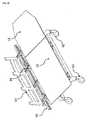
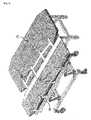
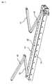
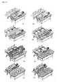
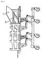
Fig. 1 is a schematic view of a patient-moving bed with a patient transfer apparatus installed thereon;Fig.2 is a schematic view of the patient-moving bed connected with a patient bed;Fig.3 is a configuration view of a transfer arm housing;Fig.4 is a configuration view of a transfer arm;Fig.5 is a assembled view of the transfer arm and the transfer arm housing;Fig.6 is an assembled view of the transfer arm and linkages;Fig.7 is an operational view of the linkages;Fig.8 is a configuration view of the transfer arm and the transfer arm housing without the linkages;Fig.9 is a configuration view of the transfer arm without transfer arm housing rollers;Fig.10 is a view illustrating the transfer arms moving over a side protector;Fig.11 is a view illustrating a step of loading a patient onto the patient-moving bed;Fig.12 is a view illustrating a step of unloading the patient from the patient-moving bed; andFig.13 is a view illustrating a state where a movable part of a top movable board is raised up.- As shown in
Figs.1 to 6 , transfer arms (30) each equipped with transfer arm rollers (31) and transfer arm housings (34) are installed under a top movable board (10) of a patient-moving bed so that the top movable board can be easily moved over a patient bed. The transfer arm housings (34) are fixed to a frame (60) of the patient-moving bed. When the top movable board (10) of the patient-moving bed is moved over a mattress of the patient bed in order to load or unload the patient onto or from the top movable board (10), particularly in a case where the patient's body is loaded on the top movable board (10), it is not easy to move the top movable board over the patient mattress even though the rollers are equipped under the transfer arms (30). The applicant has been devised a wheeled chassis movable on the transfer arms (30) in order to overcome such a problem, as described inKR 10-2009-0053325 - A good method for easily moving the top movable board (10) over the patient bed is a method allowing the transfer arms (30) itself to easily move over the patient bed, rather than an indirect method of using the wheeled chassis etc.. In the present invention, side protectors (50) provided on the patient-moving bed is laid on the mattress of the patient bed (70), and the transfer arms (30) installed on the top movable board (10) are moved over the side protectors (50) instead of the mattress of the patient bed when moved over the patient bed, whereby the top movable board (10) loaded with the patient's body can be easily moved over the patient bed. The side protectors (50) serve as a guide rail allowing the transfer arms (30) to be easily moved over the mattress of the patient bed and also as a safety device preventing the patient-moving bed from falling down due to shift of a center of gravity when the top movable board is moved over the patient bed.
- A significant feature of the present invention lies in that a step is not required of separately installing or withdrawing the transfer arms (30) in order to load or unload the patient's body and, when the top movable board (10) is moved, the transfer arms (30) fixed to the top movable board is very easily moved by means of the transfer arm rollers (31) using, as a guide rail, the transfer arm housings (34) and the side protectors (50) installed on the patient bed. In
US 7,000,268 , a complex step is required of separately installing or withdrawing the transfer arms; however, in the present invention, when the top movable board (10) is moved, the transfer arms (30) are moved together with the board, so that a step is not separately required of installing or withdrawing the transfer arms (30). - As shown in
Figs.6 and7 , linkages (42, 43) are connected between the top movable board (10) and each transfer arm (30) and serve as a pivot when the top movable board (10) is inclined. The linkages allow the top movable board (10) to be inclined toward the patient so that the patient's body can be easily loaded or unloaded. When the top movable board (10) is moved toward the patient in order to load the patient on the patient-moving bed, the patient erects his/her back while lying down. At this time, if the top movable board (10) is also erected so as to face the patient's back, the patient leans the back against the top movable board, and if the top movable board is laid down, the patient's body is naturally laid on the top movable board. Furthermore, when the patient's body is to be unloaded from the patient-moving bed, the top movable board (10) is moved toward the patient bed (70) and then inclined, whereby the patient's body can naturally slide. Fig.8 shows a structure of the transfer arm (30) and the transfer arm housing (34) with no linkages. In a case where the linkages do not present, the transfer arm (30) is directly connected with the top movable board (10), and thus the top movable board cannot be inclined.Fig.9 shows a simple structure of the transfer arm and the transfer arm housing with no transfer arm housing rollers (35). A slight gap is present between each transfer arm roller (31) and the transfer arm housing (34) ofFig.9 , and therefore the transfer arm may be slightly inclined to thereby cause a part of the transfer arm roller (31) to contact with the transfer arm housing when the top movable board (10) is moved. At this time, the transfer arm roller (31) contacting with the transfer arm housing (34) performs a role of the transfer arm housing rollers (35), whereby the structure of the transfer arm and the transfer arm housing becomes simple. Furthermore,Fig.10 shows a state of the transfer arm (30) and the transfer arm housing (34) when the transfer arm (30) is moved over the side protector (50) and then the top movable board (10) is erected.- Steps of loading and unloading the patient onto and from the patient-moving bed are shown in
Figs.11 and12 . First, in order to load the patient onto the patient-moving bed from the patient bed, the patient-moving bed is brought alongside the patient bed as shown inFig.11(a) , and then the side protector (50) of the patient-moving bed is first laid on the patient bed (70) as shown inFig.11(b) . As shown inFig.11(c) , the top movable board (10) can be easily moved over the transfer arm housing (34) and the side protector (50) through the transfer arms. When the patient erects his/her back in order to be loaded onto the patient-moving bed as shown inFig.11(d) , the top movable board is moved toward the patient to be positioned close to the patient and then erected, and then the patient leans the back against the top movable board, as shown inFig.11(e) . At this time, when the top movable board is laid down as shown inFig.11(f) , the patient's body is naturally laid on the top movable board (10), and when the top movable board (10) is pushed toward the patient-moving bed, the transfer arms connected to the top movable board (10) are moved over the side protector (50) as shown inFig.11(f) . At this time, a great force is not required for moving the top movable board (10) since the top movable board (10) is moved over the transfer arm housings (34) and the side protector (50) through the transfer arm wheels (31). When the patient's body is completely transferred to the patient-moving bed as shown inFig.11(g) , the side protector is erected as shown inFig.11(h) . - In addition, once the patient's body is completely loaded on the patient-moving bed, movement of the top movable board (10) has to be prevented by erecting the side protectors (50) on both sides of the patient-moving bed before the patient-moving bed is moved. The side protector (50) serve to protect the patient's body from falling off the patient-moving bed during the movement of the patient and also to prevent the movement of the top movable board (10) and the transfer arms (30).
- When the patient is to be unloaded from the patient-moving bed onto the patient bed, the patient-moving bed is brought alongside the patient bed as shown in
Fig.12(a) , and then the side protector (50) of the patient-moving bed is first laid on the patient bed as shown inFig.12(b) . When the top movable board (10) loaded with the patient's body is pushed toward the patient bed as shown inFig.12(c) , the top movable board (10) is moved toward the patient bed over the transfer arm housings (34) and the side protector (50) through the transfer arms. When the top movable board (10) connected with the linkages (42,43) is inclined toward the patient bed as shown inFig.12(d) , the patient's body naturally slides down toward the patient bed as shown inFig.12(e) while the center of gravity of the patient is shifted. After the patient's body has slid down to the patient bed, the top movable board (10) is pushed again toward the patient-moving bed as shown inFigs.12(f) and 12(g) and thus easily withdrawn. - In the present invention, the top movable board (10) and the transfer arms (30) are movable in both left and right directions of the patient-moving bed, whereby a great convenience is provided.
- In moving the patient from the patient bed to the patient-moving bed or in moving the patient from the patient-moving bed to the patient bed, stability of the patient-moving bed is very important. In particular, it is very important to prevent the patient-moving bed from falling down since the center of gravity of the patient's body is shifted. After the patient-moving bed has been brought alongside the patient bed in order to transfer and loaded or unload the patient onto or from the patient-moving bed, it is important to first lock wheels (62)(
Fig.10 ) of the patient-moving bed through a wheel-locking device. In the present invention, the side protectors (50) serve as a safety device for preventing the patient-moving bed from falling down during transfer of the patient lying on the patent bed. - A very significant advantage of the present invention lies in that a step is not required of separately installing or withdrawing auxiliary device such as the transfer arms (30) etc. and the patient can be easily loaded onto the patient-moving bed without much effort by simply pushing the top movable board (10) from the patient-moving bed toward the patient to thereby load the patient on the top movable board (10) and then pushing the top movable board (10) again toward the patient-moving bed. In addition, also in a case of unloading the patient from the patient-moving bed to the patient bed, the patient can be easily unloaded from the patient-moving bed onto the patient bed without much effort by simply pushing the top movable board (10) toward the patient bed to thereby unload the patient and then pushing the top movable board again toward the patient-moving bed as shown in
Fig.12 , without a step of separately installing or withdrawing the auxiliary device. - As shown in
Fig.10 , the transfer arm housings (34) are fixed to a patient-moving bed frame (60). The patient-moving bed frame (60) with the transfer arm housings (34) installed thereon may raise a movable part (11) of the top movable board through a movable support (64)(Figs.10 and13 ) for the top movable board as necessary. In a case where the patient has to wait on the patient-moving bed for a long time, the movable part (11) of the top movable board may be raised up to thereby allow the patient to more comfortably lie, as shown inFig.13 . - There are many cases where the patient has to be transferred from the patient bed (70) onto the patient-moving bed for moving the patient from a sickroom to examination and inspection rooms. Furthermore, there are also many cases where the patient has to be transferred from the patient-moving bed onto various inspection apparatuses such as x-ray machine, MRI scanner etc.. On all such occasions, it is not easy to move the patient having problems with mobility. On all occasions of moving the patient, a lot of pains are caused to the patient and several persons have to be mobilized. Particularly, as obesity of people recently becomes severe, very great inconvenience occurs in moving the patient having a great weight.
- The present invention may be used for an apparatus which can easily move the patient having problems with mobility while causing minimum inconvenience to the patient when the patient is transferred between the patient bed and the patient-moving bed.
Claims (4)
- A patient transfer apparatus comprising:a top movable board (10) on which a patient's body can be loaded;transfer arms (30) which are connected to the top movable board and allow the top movable board to be easily moved;transfer arm housings (34) which are fixed to a frame (60) of a patient-moving bed and are configured such that the transfer arms (30) can move; andside protectors (50) which can be laid on a patient bed to thus serve as a guide rail that allows the transfer arms to be easily moved over the patient bed.
- The patient transfer apparatus according to claim 1, wherein linkages (42, 43) are installed between the top movable board (10) and each transfer arm (30), which linkages serve as a pivot that allows the top movable board (10) to be easily inclined when the patient's body is loaded or unloaded.
- The patient transfer apparatus according to claim 2, wherein the length of the upper linkage (42) is different from that of the lower linkage (43) so that a position of the pivot of the linkages can be effectively adjusted when the top movable board (10) is inclined.
- The patient transfer apparatus according to claim 1, wherein a movable part (11) of the top movable board is installed so that fatigue of the patient can be relieved by raising up a part of the top movable board in a case where the patient has to stay on the patient-moving bed for a long time.
Applications Claiming Priority (2)
| Application Number | Priority Date | Filing Date | Title |
|---|---|---|---|
| KR20120050558AKR101355756B1 (en) | 2012-05-12 | 2012-05-12 | Patient Transfer Apparatus Using Side Safety Rails |
| PCT/KR2013/004196WO2013172608A1 (en) | 2012-05-12 | 2013-05-11 | Patient transfer apparatus using side protector |
Publications (3)
| Publication Number | Publication Date |
|---|---|
| EP2848238A1true EP2848238A1 (en) | 2015-03-18 |
| EP2848238A4 EP2848238A4 (en) | 2016-01-06 |
| EP2848238B1 EP2848238B1 (en) | 2017-11-01 |
Family
ID=49583966
Family Applications (1)
| Application Number | Title | Priority Date | Filing Date |
|---|---|---|---|
| EP13791309.1AActiveEP2848238B1 (en) | 2012-05-12 | 2013-05-11 | Patient transfer apparatus using side protector |
Country Status (7)
| Country | Link |
|---|---|
| US (1) | US9351893B2 (en) |
| EP (1) | EP2848238B1 (en) |
| JP (1) | JP2015515908A (en) |
| KR (1) | KR101355756B1 (en) |
| CN (1) | CN104582666B (en) |
| HU (1) | HUE035663T2 (en) |
| WO (1) | WO2013172608A1 (en) |
Cited By (1)
| Publication number | Priority date | Publication date | Assignee | Title |
|---|---|---|---|---|
| CN109620561A (en)* | 2019-02-12 | 2019-04-16 | 中国人民解放军陆军特色医学中心 | A kind of stretcher and stretcher group |
Families Citing this family (11)
| Publication number | Priority date | Publication date | Assignee | Title |
|---|---|---|---|---|
| KR101355756B1 (en)* | 2012-05-12 | 2014-01-27 | 제양규 | Patient Transfer Apparatus Using Side Safety Rails |
| CN104546319B (en)* | 2015-01-27 | 2017-03-29 | 大连交通大学 | A kind of disability old man's bathing transfer stretcher |
| WO2017066616A1 (en) | 2015-10-14 | 2017-04-20 | Qfix Systems, Llc | Mri compatible patient trolley |
| US11737934B2 (en) | 2015-10-14 | 2023-08-29 | Qfix Systems, Llc | MRI compatible patient trolley |
| CN106420225A (en)* | 2016-11-21 | 2017-02-22 | 天津尚吉液压设备有限公司 | Movable medical transferring bed |
| JOP20180051A1 (en)* | 2018-05-15 | 2019-11-15 | Jordan Univ Of Science And Technology | Patient transfer apparatus and method |
| US10617583B1 (en) | 2019-09-25 | 2020-04-14 | King Sand University | Bed with retractable side extension |
| US10980688B1 (en) | 2020-03-05 | 2021-04-20 | King Saud University | Hospital bed with pivoting side rail |
| CN111920593B (en)* | 2020-08-12 | 2022-12-20 | 梅爪宠物医疗有限公司 | Medical multifunctional combined wheelchair |
| CN114246738A (en)* | 2021-12-20 | 2022-03-29 | 上海大学 | A delivery mechanism and control method for a tumor targeted therapy device |
| CN119112515A (en)* | 2024-09-11 | 2024-12-13 | 南京江北医院 | A transport bed for critical care |
Family Cites Families (30)
| Publication number | Priority date | Publication date | Assignee | Title |
|---|---|---|---|---|
| US793168A (en)* | 1904-08-31 | 1905-06-27 | Frank M Abrams | Baby-crib. |
| US2113286A (en)* | 1936-02-15 | 1938-04-05 | White Joseph | Hospital bed |
| US2542963A (en)* | 1945-10-17 | 1951-02-20 | Knox | Hospital table for moving patients |
| US3293668A (en)* | 1964-09-01 | 1966-12-27 | Docona Associates | Article transfer |
| US3344445A (en)* | 1966-08-12 | 1967-10-03 | Institutional Ind Inc | Side panel construction for stretcher-beds |
| US3792500A (en)* | 1972-04-06 | 1974-02-19 | M Swara | Apparatus and method for transferring a body between horizontally spaced supported positions |
| US4259756A (en) | 1979-08-28 | 1981-04-07 | Pace Paul D | Moveable top stretcher |
| US4274168A (en)* | 1979-09-17 | 1981-06-23 | Depowski Norma M | Patient transfer apparatus |
| DE3682501D1 (en)* | 1985-08-13 | 1991-12-19 | William Brian Plewright | VEHICLE FOR PATIENT RELOCATION AND REQUIREMENT. |
| US4873732A (en)* | 1988-10-24 | 1989-10-17 | Roberto Perez | Trauma stretcher |
| US5584082A (en)* | 1993-09-17 | 1996-12-17 | Easy Lift Care Products, Inc. | Convertible gurney |
| US5522100A (en)* | 1994-05-06 | 1996-06-04 | Stryker Corporation | Stretcher with transfer board which retracts between litter and frame |
| SE9600957D0 (en)* | 1996-03-13 | 1996-03-13 | Tom Lindell | Device for brits |
| US6212712B1 (en)* | 1999-04-20 | 2001-04-10 | Richard Hardy Topp | Mobile stretcher with lateral recumbant mechanism |
| US6484332B2 (en)* | 1999-12-08 | 2002-11-26 | Med-Tec Iowa, Inc. | System for vertical to horizontal movement and lateral movement of a patient |
| KR100429034B1 (en) | 2000-12-19 | 2004-05-03 | 주식회사 필셋 | Automatic adjustment of the angle of the satellite antenna |
| JP3988032B2 (en)* | 2001-04-24 | 2007-10-10 | 恭三 野村 | Sliding bed |
| EP1480591A4 (en) | 2002-02-18 | 2007-12-05 | Dane Ind | Patient transfer and transport device |
| KR20030037260A (en) | 2003-04-28 | 2003-05-12 | 허세진 | Method, Program, Media, and Device to register various service, and authentication member, and set up service, register transmission control server membership, transmit spam compensation way, authentication way, and non-authentication way of mail, manage site united login and use, advertising, personal office service, advertising mail transmission and receiving management service in spam compensation authenticated mail and authenticated mail, preventing to loose leading to register membership |
| DE102004052265B4 (en) | 2003-12-04 | 2021-09-09 | Siemens Healthcare Gmbh | Medical examination and therapy device with a storage device |
| JP4415149B2 (en) | 2004-04-20 | 2010-02-17 | 国立大学法人広島大学 | Transfer support mechanism, stretcher and bed equipped with this transfer support mechanism |
| KR100619432B1 (en) | 2004-06-17 | 2006-09-19 | 박신택 | Patient transport bed |
| US7603729B2 (en) | 2005-10-07 | 2009-10-20 | Conmedisys, Inc. | Patient lift and transfer device |
| KR100926223B1 (en) | 2007-11-23 | 2009-11-09 | (주)아모레퍼시픽 | Simultaneous Analysis of Two or More Amadori Compounds Using Ion Chromatography |
| US8171580B2 (en)* | 2008-06-17 | 2012-05-08 | Medtec, Inc. | Patient transfer system for use in stereotactic radiation therapy |
| CN101433486B (en)* | 2008-11-20 | 2010-12-08 | 王士达 | Medical handcart for patient with adjustable bed board |
| KR20100134949A (en)* | 2009-06-16 | 2010-12-24 | 제양규 | Patient transfer device |
| KR101027075B1 (en) | 2010-05-03 | 2011-04-05 | 김우진 | Patient rollaway bed |
| KR101355756B1 (en)* | 2012-05-12 | 2014-01-27 | 제양규 | Patient Transfer Apparatus Using Side Safety Rails |
| DE102013217539A1 (en)* | 2013-09-03 | 2015-03-05 | Siemens Aktiengesellschaft | Patient storage device and a medical imaging device with the patient support device |
- 2012
- 2012-05-12KRKR20120050558Apatent/KR101355756B1/enactiveActive
- 2013
- 2013-05-11USUS14/400,393patent/US9351893B2/ennot_activeExpired - Fee Related
- 2013-05-11JPJP2015511381Apatent/JP2015515908A/enactivePending
- 2013-05-11EPEP13791309.1Apatent/EP2848238B1/enactiveActive
- 2013-05-11WOPCT/KR2013/004196patent/WO2013172608A1/enactiveApplication Filing
- 2013-05-11HUHUE13791309Apatent/HUE035663T2/enunknown
- 2013-05-11CNCN201380023735.XApatent/CN104582666B/ennot_activeExpired - Fee Related
Cited By (1)
| Publication number | Priority date | Publication date | Assignee | Title |
|---|---|---|---|---|
| CN109620561A (en)* | 2019-02-12 | 2019-04-16 | 中国人民解放军陆军特色医学中心 | A kind of stretcher and stretcher group |
Also Published As
| Publication number | Publication date |
|---|---|
| EP2848238A4 (en) | 2016-01-06 |
| KR101355756B1 (en) | 2014-01-27 |
| KR20130126413A (en) | 2013-11-20 |
| US20150135433A1 (en) | 2015-05-21 |
| WO2013172608A1 (en) | 2013-11-21 |
| EP2848238B1 (en) | 2017-11-01 |
| JP2015515908A (en) | 2015-06-04 |
| CN104582666A (en) | 2015-04-29 |
| CN104582666B (en) | 2018-01-19 |
| US9351893B2 (en) | 2016-05-31 |
| HUE035663T2 (en) | 2018-05-28 |
Similar Documents
| Publication | Publication Date | Title |
|---|---|---|
| EP2848238B1 (en) | Patient transfer apparatus using side protector | |
| US20120066831A1 (en) | Patient transfer apparatus | |
| EP4119086B1 (en) | Mobile support and storage system for a medical device | |
| US8316480B2 (en) | Mobile cantilever transfer device | |
| AU2008214122B2 (en) | Patient repositioning and limb management system | |
| CN108366896B (en) | Patient trolleys and patient transfer units | |
| US8966685B2 (en) | Flexible bariatric overlay | |
| US10869796B1 (en) | Rotating leg lift machine | |
| CN104116603A (en) | Medical lifting type transfer system | |
| CN110882108A (en) | A gastroenterology operating bed and transfer bed | |
| US8997276B2 (en) | Patient lift | |
| CN112021971A (en) | Movable auxiliary bathing device and operation method thereof | |
| KR101448887B1 (en) | standing / sitting assist and transfer system using rotational mechanism | |
| CN108618898A (en) | A kind of auxiliary examination medical bed | |
| CN107095749A (en) | A kind of multi-functional bed body and robot massage bed | |
| KR101704998B1 (en) | Patient transfer apparatus | |
| CN209808776U (en) | Automatic transfer bed for medical care patient | |
| KR102351617B1 (en) | Medical bed for transfering patient | |
| CN209172719U (en) | A kind of transportation of patients hospital bed | |
| RU101633U1 (en) | MEDICAL ROLLER | |
| JP4605678B2 (en) | Tilt table | |
| CN111888103A (en) | Patient nursing is with transporting stretcher | |
| WO2019220478A2 (en) | Patient transfer apparatus and method |
Legal Events
| Date | Code | Title | Description |
|---|---|---|---|
| PUAI | Public reference made under article 153(3) epc to a published international application that has entered the european phase | Free format text:ORIGINAL CODE: 0009012 | |
| 17P | Request for examination filed | Effective date:20141212 | |
| AK | Designated contracting states | Kind code of ref document:A1 Designated state(s):AL AT BE BG CH CY CZ DE DK EE ES FI FR GB GR HR HU IE IS IT LI LT LU LV MC MK MT NL NO PL PT RO RS SE SI SK SM TR | |
| AX | Request for extension of the european patent | Extension state:BA ME | |
| DAX | Request for extension of the european patent (deleted) | ||
| RA4 | Supplementary search report drawn up and despatched (corrected) | Effective date:20151208 | |
| RIC1 | Information provided on ipc code assigned before grant | Ipc:A61G 1/02 20060101ALN20151202BHEP Ipc:A61G 7/10 20060101AFI20151202BHEP Ipc:A61G 7/05 20060101ALN20151202BHEP | |
| 17Q | First examination report despatched | Effective date:20160913 | |
| RIC1 | Information provided on ipc code assigned before grant | Ipc:A61G 7/10 20060101AFI20170322BHEP Ipc:A61G 7/05 20060101ALN20170322BHEP Ipc:A61G 1/02 20060101ALN20170322BHEP | |
| GRAP | Despatch of communication of intention to grant a patent | Free format text:ORIGINAL CODE: EPIDOSNIGR1 | |
| INTG | Intention to grant announced | Effective date:20170512 | |
| GRAS | Grant fee paid | Free format text:ORIGINAL CODE: EPIDOSNIGR3 | |
| GRAA | (expected) grant | Free format text:ORIGINAL CODE: 0009210 | |
| AK | Designated contracting states | Kind code of ref document:B1 Designated state(s):AL AT BE BG CH CY CZ DE DK EE ES FI FR GB GR HR HU IE IS IT LI LT LU LV MC MK MT NL NO PL PT RO RS SE SI SK SM TR | |
| REG | Reference to a national code | Ref country code:GB Ref legal event code:FG4D | |
| REG | Reference to a national code | Ref country code:CH Ref legal event code:EP Ref country code:AT Ref legal event code:REF Ref document number:941274 Country of ref document:AT Kind code of ref document:T Effective date:20171115 | |
| REG | Reference to a national code | Ref country code:IE Ref legal event code:FG4D | |
| REG | Reference to a national code | Ref country code:DE Ref legal event code:R096 Ref document number:602013028820 Country of ref document:DE | |
| REG | Reference to a national code | Ref country code:NL Ref legal event code:MP Effective date:20171101 | |
| REG | Reference to a national code | Ref country code:LT Ref legal event code:MG4D | |
| REG | Reference to a national code | Ref country code:AT Ref legal event code:MK05 Ref document number:941274 Country of ref document:AT Kind code of ref document:T Effective date:20171101 | |
| PG25 | Lapsed in a contracting state [announced via postgrant information from national office to epo] | Ref country code:LT Free format text:LAPSE BECAUSE OF FAILURE TO SUBMIT A TRANSLATION OF THE DESCRIPTION OR TO PAY THE FEE WITHIN THE PRESCRIBED TIME-LIMIT Effective date:20171101 Ref country code:FI Free format text:LAPSE BECAUSE OF FAILURE TO SUBMIT A TRANSLATION OF THE DESCRIPTION OR TO PAY THE FEE WITHIN THE PRESCRIBED TIME-LIMIT Effective date:20171101 Ref country code:NL Free format text:LAPSE BECAUSE OF FAILURE TO SUBMIT A TRANSLATION OF THE DESCRIPTION OR TO PAY THE FEE WITHIN THE PRESCRIBED TIME-LIMIT Effective date:20171101 Ref country code:NO Free format text:LAPSE BECAUSE OF FAILURE TO SUBMIT A TRANSLATION OF THE DESCRIPTION OR TO PAY THE FEE WITHIN THE PRESCRIBED TIME-LIMIT Effective date:20180201 Ref country code:ES Free format text:LAPSE BECAUSE OF FAILURE TO SUBMIT A TRANSLATION OF THE DESCRIPTION OR TO PAY THE FEE WITHIN THE PRESCRIBED TIME-LIMIT Effective date:20171101 Ref country code:SE Free format text:LAPSE BECAUSE OF FAILURE TO SUBMIT A TRANSLATION OF THE DESCRIPTION OR TO PAY THE FEE WITHIN THE PRESCRIBED TIME-LIMIT Effective date:20171101 | |
| REG | Reference to a national code | Ref country code:HU Ref legal event code:AG4A Ref document number:E035663 Country of ref document:HU | |
| PG25 | Lapsed in a contracting state [announced via postgrant information from national office to epo] | Ref country code:BG Free format text:LAPSE BECAUSE OF FAILURE TO SUBMIT A TRANSLATION OF THE DESCRIPTION OR TO PAY THE FEE WITHIN THE PRESCRIBED TIME-LIMIT Effective date:20180201 Ref country code:AT Free format text:LAPSE BECAUSE OF FAILURE TO SUBMIT A TRANSLATION OF THE DESCRIPTION OR TO PAY THE FEE WITHIN THE PRESCRIBED TIME-LIMIT Effective date:20171101 Ref country code:IS Free format text:LAPSE BECAUSE OF FAILURE TO SUBMIT A TRANSLATION OF THE DESCRIPTION OR TO PAY THE FEE WITHIN THE PRESCRIBED TIME-LIMIT Effective date:20180301 Ref country code:RS Free format text:LAPSE BECAUSE OF FAILURE TO SUBMIT A TRANSLATION OF THE DESCRIPTION OR TO PAY THE FEE WITHIN THE PRESCRIBED TIME-LIMIT Effective date:20171101 Ref country code:LV Free format text:LAPSE BECAUSE OF FAILURE TO SUBMIT A TRANSLATION OF THE DESCRIPTION OR TO PAY THE FEE WITHIN THE PRESCRIBED TIME-LIMIT Effective date:20171101 Ref country code:HR Free format text:LAPSE BECAUSE OF FAILURE TO SUBMIT A TRANSLATION OF THE DESCRIPTION OR TO PAY THE FEE WITHIN THE PRESCRIBED TIME-LIMIT Effective date:20171101 Ref country code:GR Free format text:LAPSE BECAUSE OF FAILURE TO SUBMIT A TRANSLATION OF THE DESCRIPTION OR TO PAY THE FEE WITHIN THE PRESCRIBED TIME-LIMIT Effective date:20180202 | |
| PG25 | Lapsed in a contracting state [announced via postgrant information from national office to epo] | Ref country code:CY Free format text:LAPSE BECAUSE OF FAILURE TO SUBMIT A TRANSLATION OF THE DESCRIPTION OR TO PAY THE FEE WITHIN THE PRESCRIBED TIME-LIMIT Effective date:20171101 Ref country code:EE Free format text:LAPSE BECAUSE OF FAILURE TO SUBMIT A TRANSLATION OF THE DESCRIPTION OR TO PAY THE FEE WITHIN THE PRESCRIBED TIME-LIMIT Effective date:20171101 Ref country code:DK Free format text:LAPSE BECAUSE OF FAILURE TO SUBMIT A TRANSLATION OF THE DESCRIPTION OR TO PAY THE FEE WITHIN THE PRESCRIBED TIME-LIMIT Effective date:20171101 Ref country code:SK Free format text:LAPSE BECAUSE OF FAILURE TO SUBMIT A TRANSLATION OF THE DESCRIPTION OR TO PAY THE FEE WITHIN THE PRESCRIBED TIME-LIMIT Effective date:20171101 | |
| REG | Reference to a national code | Ref country code:DE Ref legal event code:R097 Ref document number:602013028820 Country of ref document:DE | |
| PG25 | Lapsed in a contracting state [announced via postgrant information from national office to epo] | Ref country code:IT Free format text:LAPSE BECAUSE OF FAILURE TO SUBMIT A TRANSLATION OF THE DESCRIPTION OR TO PAY THE FEE WITHIN THE PRESCRIBED TIME-LIMIT Effective date:20171101 Ref country code:SM Free format text:LAPSE BECAUSE OF FAILURE TO SUBMIT A TRANSLATION OF THE DESCRIPTION OR TO PAY THE FEE WITHIN THE PRESCRIBED TIME-LIMIT Effective date:20171101 Ref country code:RO Free format text:LAPSE BECAUSE OF FAILURE TO SUBMIT A TRANSLATION OF THE DESCRIPTION OR TO PAY THE FEE WITHIN THE PRESCRIBED TIME-LIMIT Effective date:20171101 Ref country code:PL Free format text:LAPSE BECAUSE OF FAILURE TO SUBMIT A TRANSLATION OF THE DESCRIPTION OR TO PAY THE FEE WITHIN THE PRESCRIBED TIME-LIMIT Effective date:20171101 | |
| PLBE | No opposition filed within time limit | Free format text:ORIGINAL CODE: 0009261 | |
| STAA | Information on the status of an ep patent application or granted ep patent | Free format text:STATUS: NO OPPOSITION FILED WITHIN TIME LIMIT | |
| REG | Reference to a national code | Ref country code:FR Ref legal event code:PLFP Year of fee payment:6 | |
| 26N | No opposition filed | Effective date:20180802 | |
| PG25 | Lapsed in a contracting state [announced via postgrant information from national office to epo] | Ref country code:SI Free format text:LAPSE BECAUSE OF FAILURE TO SUBMIT A TRANSLATION OF THE DESCRIPTION OR TO PAY THE FEE WITHIN THE PRESCRIBED TIME-LIMIT Effective date:20171101 | |
| REG | Reference to a national code | Ref country code:CH Ref legal event code:PL | |
| REG | Reference to a national code | Ref country code:BE Ref legal event code:MM Effective date:20180531 | |
| PG25 | Lapsed in a contracting state [announced via postgrant information from national office to epo] | Ref country code:MC Free format text:LAPSE BECAUSE OF FAILURE TO SUBMIT A TRANSLATION OF THE DESCRIPTION OR TO PAY THE FEE WITHIN THE PRESCRIBED TIME-LIMIT Effective date:20171101 | |
| REG | Reference to a national code | Ref country code:IE Ref legal event code:MM4A | |
| PG25 | Lapsed in a contracting state [announced via postgrant information from national office to epo] | Ref country code:CH Free format text:LAPSE BECAUSE OF NON-PAYMENT OF DUE FEES Effective date:20180531 Ref country code:LI Free format text:LAPSE BECAUSE OF NON-PAYMENT OF DUE FEES Effective date:20180531 | |
| PG25 | Lapsed in a contracting state [announced via postgrant information from national office to epo] | Ref country code:LU Free format text:LAPSE BECAUSE OF NON-PAYMENT OF DUE FEES Effective date:20180511 | |
| PG25 | Lapsed in a contracting state [announced via postgrant information from national office to epo] | Ref country code:IE Free format text:LAPSE BECAUSE OF NON-PAYMENT OF DUE FEES Effective date:20180511 | |
| PG25 | Lapsed in a contracting state [announced via postgrant information from national office to epo] | Ref country code:BE Free format text:LAPSE BECAUSE OF NON-PAYMENT OF DUE FEES Effective date:20180531 | |
| PGFP | Annual fee paid to national office [announced via postgrant information from national office to epo] | Ref country code:BE Payment date:20190516 Year of fee payment:7 | |
| PG25 | Lapsed in a contracting state [announced via postgrant information from national office to epo] | Ref country code:MT Free format text:LAPSE BECAUSE OF NON-PAYMENT OF DUE FEES Effective date:20180511 | |
| PG25 | Lapsed in a contracting state [announced via postgrant information from national office to epo] | Ref country code:TR Free format text:LAPSE BECAUSE OF FAILURE TO SUBMIT A TRANSLATION OF THE DESCRIPTION OR TO PAY THE FEE WITHIN THE PRESCRIBED TIME-LIMIT Effective date:20171101 | |
| PG25 | Lapsed in a contracting state [announced via postgrant information from national office to epo] | Ref country code:PT Free format text:LAPSE BECAUSE OF FAILURE TO SUBMIT A TRANSLATION OF THE DESCRIPTION OR TO PAY THE FEE WITHIN THE PRESCRIBED TIME-LIMIT Effective date:20171101 | |
| PG25 | Lapsed in a contracting state [announced via postgrant information from national office to epo] | Ref country code:MK Free format text:LAPSE BECAUSE OF NON-PAYMENT OF DUE FEES Effective date:20171101 | |
| PG25 | Lapsed in a contracting state [announced via postgrant information from national office to epo] | Ref country code:AL Free format text:LAPSE BECAUSE OF FAILURE TO SUBMIT A TRANSLATION OF THE DESCRIPTION OR TO PAY THE FEE WITHIN THE PRESCRIBED TIME-LIMIT Effective date:20171101 | |
| PG25 | Lapsed in a contracting state [announced via postgrant information from national office to epo] | Ref country code:CZ Free format text:LAPSE BECAUSE OF NON-PAYMENT OF DUE FEES Effective date:20200511 Ref country code:HU Free format text:LAPSE BECAUSE OF NON-PAYMENT OF DUE FEES Effective date:20200512 | |
| PGFP | Annual fee paid to national office [announced via postgrant information from national office to epo] | Ref country code:GB Payment date:20220530 Year of fee payment:10 Ref country code:FR Payment date:20220531 Year of fee payment:10 | |
| GBPC | Gb: european patent ceased through non-payment of renewal fee | Effective date:20230511 | |
| PG25 | Lapsed in a contracting state [announced via postgrant information from national office to epo] | Ref country code:GB Free format text:LAPSE BECAUSE OF NON-PAYMENT OF DUE FEES Effective date:20230511 | |
| PG25 | Lapsed in a contracting state [announced via postgrant information from national office to epo] | Ref country code:FR Free format text:LAPSE BECAUSE OF NON-PAYMENT OF DUE FEES Effective date:20230531 | |
| PGFP | Annual fee paid to national office [announced via postgrant information from national office to epo] | Ref country code:DE Payment date:20250530 Year of fee payment:13 |