EP2848144B1 - Sole provided with outer sole and midsole - Google Patents
Sole provided with outer sole and midsoleDownload PDFInfo
- Publication number
- EP2848144B1 EP2848144B1EP12876567.4AEP12876567AEP2848144B1EP 2848144 B1EP2848144 B1EP 2848144B1EP 12876567 AEP12876567 AEP 12876567AEP 2848144 B1EP2848144 B1EP 2848144B1
- Authority
- EP
- European Patent Office
- Prior art keywords
- midsole
- lateral
- hardness
- toe
- roll
- Prior art date
- Legal status (The legal status is an assumption and is not a legal conclusion. Google has not performed a legal analysis and makes no representation as to the accuracy of the status listed.)
- Active
Links
Images


Classifications
- A—HUMAN NECESSITIES
- A43—FOOTWEAR
- A43B—CHARACTERISTIC FEATURES OF FOOTWEAR; PARTS OF FOOTWEAR
- A43B3/00—Footwear characterised by the shape or the use
- A43B3/0036—Footwear characterised by the shape or the use characterised by a special shape or design
- A43B3/0047—Footwear characterised by the shape or the use characterised by a special shape or design parts having a male and corresponding female profile to fit together, e.g. form-fit
- A—HUMAN NECESSITIES
- A43—FOOTWEAR
- A43B—CHARACTERISTIC FEATURES OF FOOTWEAR; PARTS OF FOOTWEAR
- A43B13/00—Soles; Sole-and-heel integral units
- A43B13/14—Soles; Sole-and-heel integral units characterised by the constructive form
- A—HUMAN NECESSITIES
- A43—FOOTWEAR
- A43B—CHARACTERISTIC FEATURES OF FOOTWEAR; PARTS OF FOOTWEAR
- A43B13/00—Soles; Sole-and-heel integral units
- A43B13/02—Soles; Sole-and-heel integral units characterised by the material
- A43B13/12—Soles with several layers of different materials
- A43B13/125—Soles with several layers of different materials characterised by the midsole or middle layer
- A43B13/127—Soles with several layers of different materials characterised by the midsole or middle layer the midsole being multilayer
- A—HUMAN NECESSITIES
- A43—FOOTWEAR
- A43B—CHARACTERISTIC FEATURES OF FOOTWEAR; PARTS OF FOOTWEAR
- A43B13/00—Soles; Sole-and-heel integral units
- A43B13/14—Soles; Sole-and-heel integral units characterised by the constructive form
- A43B13/16—Pieced soles
- A—HUMAN NECESSITIES
- A43—FOOTWEAR
- A43B—CHARACTERISTIC FEATURES OF FOOTWEAR; PARTS OF FOOTWEAR
- A43B13/00—Soles; Sole-and-heel integral units
- A43B13/14—Soles; Sole-and-heel integral units characterised by the constructive form
- A43B13/18—Resilient soles
- A43B13/187—Resiliency achieved by the features of the material, e.g. foam, non liquid materials
- A43B13/188—Differential cushioning regions
- A—HUMAN NECESSITIES
- A43—FOOTWEAR
- A43B—CHARACTERISTIC FEATURES OF FOOTWEAR; PARTS OF FOOTWEAR
- A43B5/00—Footwear for sporting purposes
- A43B5/10—Tennis shoes
- A—HUMAN NECESSITIES
- A43—FOOTWEAR
- A43B—CHARACTERISTIC FEATURES OF FOOTWEAR; PARTS OF FOOTWEAR
- A43B7/00—Footwear with health or hygienic arrangements
- A43B7/14—Footwear with health or hygienic arrangements with foot-supporting parts
- A43B7/1405—Footwear with health or hygienic arrangements with foot-supporting parts with pads or holes on one or more locations, or having an anatomical or curved form
- A43B7/1415—Footwear with health or hygienic arrangements with foot-supporting parts with pads or holes on one or more locations, or having an anatomical or curved form characterised by the location under the foot
- A43B7/142—Footwear with health or hygienic arrangements with foot-supporting parts with pads or holes on one or more locations, or having an anatomical or curved form characterised by the location under the foot situated under the medial arch, i.e. under the navicular or cuneiform bones
- A—HUMAN NECESSITIES
- A43—FOOTWEAR
- A43B—CHARACTERISTIC FEATURES OF FOOTWEAR; PARTS OF FOOTWEAR
- A43B7/00—Footwear with health or hygienic arrangements
- A43B7/14—Footwear with health or hygienic arrangements with foot-supporting parts
- A43B7/1405—Footwear with health or hygienic arrangements with foot-supporting parts with pads or holes on one or more locations, or having an anatomical or curved form
- A43B7/1415—Footwear with health or hygienic arrangements with foot-supporting parts with pads or holes on one or more locations, or having an anatomical or curved form characterised by the location under the foot
- A43B7/1425—Footwear with health or hygienic arrangements with foot-supporting parts with pads or holes on one or more locations, or having an anatomical or curved form characterised by the location under the foot situated under the ball of the foot, i.e. the joint between the first metatarsal and first phalange
- A—HUMAN NECESSITIES
- A43—FOOTWEAR
- A43B—CHARACTERISTIC FEATURES OF FOOTWEAR; PARTS OF FOOTWEAR
- A43B7/00—Footwear with health or hygienic arrangements
- A43B7/14—Footwear with health or hygienic arrangements with foot-supporting parts
- A43B7/1405—Footwear with health or hygienic arrangements with foot-supporting parts with pads or holes on one or more locations, or having an anatomical or curved form
- A43B7/1415—Footwear with health or hygienic arrangements with foot-supporting parts with pads or holes on one or more locations, or having an anatomical or curved form characterised by the location under the foot
- A43B7/143—Footwear with health or hygienic arrangements with foot-supporting parts with pads or holes on one or more locations, or having an anatomical or curved form characterised by the location under the foot situated under the lateral arch, i.e. the cuboid bone
- A—HUMAN NECESSITIES
- A43—FOOTWEAR
- A43B—CHARACTERISTIC FEATURES OF FOOTWEAR; PARTS OF FOOTWEAR
- A43B7/00—Footwear with health or hygienic arrangements
- A43B7/14—Footwear with health or hygienic arrangements with foot-supporting parts
- A43B7/1405—Footwear with health or hygienic arrangements with foot-supporting parts with pads or holes on one or more locations, or having an anatomical or curved form
- A43B7/1415—Footwear with health or hygienic arrangements with foot-supporting parts with pads or holes on one or more locations, or having an anatomical or curved form characterised by the location under the foot
- A43B7/144—Footwear with health or hygienic arrangements with foot-supporting parts with pads or holes on one or more locations, or having an anatomical or curved form characterised by the location under the foot situated under the heel, i.e. the calcaneus bone
Definitions
- the present inventionrelates to a structure of a shoe sole suitable for court sports such as tennis and basketball, for example.
- the first and second patent documentsdisclose increasing the hardness of a lateral portion of the midsole. Such a structure is likely to support the force acting upon the lateral side of the foot when changing directions in a court sport, etc.
- the lateral portion of the midsole having a high hardnessis rolled up, and such a roll-up portion serves to prevent a lateral shake.
- the roll-up portionis likely to collapse and the roll-up portion is likely to be compressed by the resin stabilizer, whereby the lateral shake is likely to increase.
- an object of the first inventionrelated to a shoe sole, is to improve the lateral shake preventing function while preventing the lowering of the bendability of the sole and the lowering of the impact-absorbing property via the midsole in the vicinity of the foot sole.
- an object of the second inventionis to provide tennis shoes for women, etc., with which the moment around the knee is reduced.
- the first inventionin one aspect is a shoe sole including an outsole 2 having a tread surface to be in contact with a road surface, and a midsole 1 arranged on the outsole 2, wherein:
- the hardness of the lateral portion 40 of the lower midsole 4 and the lateral roll-up portion 42is higher than the hardness of the medial portion 41 and the lateral portion 30 of the upper midsole 3, and therefore the lateral roll-up portion 42 is supported by the hard lateral portion 40 of the lower midsole 4 and will unlikely collapse.
- the hard lateral roll-up portion 42will unlikely be deformed in compressive deformation. Therefore, it is easy to prevent a lateral shake on the lateral side.
- the hardness of the lateral portion 30 of the upper midsole 3is low as compared with the lateral roll-up portion 42. Therefore, the lateral portion 30 of the upper midsole 3 is likely to conform to the unevenness of the foot sole, and the bendability of the sole may be less likely to be detracted from. The impact-absorbing property is also less likely to be detracted from.
- a rubber outsole and a stabilizer made of a non-foamed body of a resinhave been used to support the lateral side of the foot from the side.
- these membersare harder and heavier than the foamed body of a resin of the midsole, and will therefore likely lead to a decrease in the athletic functionality such as foot bendability.
- the roll-up portionis formed by the midsole made of a foamed body of a resin, thereby realizing an appropriate hardness and a light weight, and therefore it will unlikely lead to a decrease in the bendability of the foot or a decrease in the athletic functionality.
- US 2010/287792shows another prior art sole, with different midsole layers.
- the lateral portion 30 of the upper midsole 3supports a lower surface of a lateral side of a fore foot section of the foot; and the high-hardness lateral roll-up portion 42 of the lower midsole 4 covers a lateral side surface of a head 05 of a metatarsal bone of a fifth toe so as to support a lateral side of the head 05 in the fore foot section.
- the lateral side of the head 05 of the metatarsal bone of the fifth toeis supported by the high-hardness lateral roll-up portion 42 in the present embodiment. This will prevent the lateral shake of the head 05 of the metatarsal bone of the fifth toe, i.e., the ball of the little toe.
- the high-hardness lateral portion 40 of the lower midsole 4covers a lower surface of the metatarsal bone of the fifth toe from the head 05 to a bottom 051 thereof; and the low-hardness medial portion 41 of the lower midsole 4 covers a lower surface of a metatarsal bone of a first toe from a head 01 to a bottom 011 thereof and a lower surface of a proximal phalanx B3 1 .
- the hardness of the medial portion 41 of the lower midsole 4is lower than the hardness of the lateral portion 40, and therefore the bendability of the sole may be less likely to be detracted from. Moreover, the impact-absorbing property is less likely to be detracted from.
- a bottomrefers to a portion of each bone that is close to the posterior joint and that is slightly expanding to a greater thickness and it is referred to also as a proximal head.
- a headrefers to a portion of each bone that is close to the anterior joint and that is slightly expanding to a greater thickness and it is referred to also as a distal head.
- a shaftrefers to a portion between the bottom and the head, and the thickness thereof typically changes smoothly.
- the lateral portion 30 of the upper midsole 3is narrowed in an area of the metatarsal bone of the fifth toe; and the lateral roll-up portion 42 of the lower midsole 4 is rolled up in an upward direction in the area of the narrowed upper midsole 3.
- the lateral roll-up portion 42rises from the lower midsole 4 without the volume of the lateral roll-up portion 42 of the lower midsole 4 decreasing and without the volume of the area extending from the lateral portion 40 of the lower midsole 4 to the lateral roll-up portion 42 decreasing. Therefore, with the hard lateral roll-up portion 42, it is possible to prevent the lateral shake of the head 05 of the metatarsal bone of the fifth toe.
- a hardness of a medial portion 31 of the upper midsole 3is a fourth hardness lower than the second hardness and the third hardness.
- the medial portion 31 of the upper midsole 3is soft, the upper surface of the midsole will be tilted in a diagonally downward direction from the lateral side toward the medial side upon landing on one foot. Therefore, with tennis shoes for women, or the like, a moment which would be a burden on the knee is unlikely to occur upon landing on one foot.
- the lateral portion 30 of the upper midsole 3covers a lower surface of the metatarsal bone of the fifth toe from the head 05 to the bottom 051 thereof; and the medial portion 31 of the upper midsole 3 covers a lower surface of the metatarsal bone of the first toe from the head 01 to the bottom 011 thereof and a lower surface of the proximal phalanx B3 1 .
- the shoe solefurther includes a stabilizer 5, made of a non-foamed body of a resin, for example, arranged along a lateral side surface of the lateral roll-up portion 42 further on a lateral side of the lateral roll-up portion 42.
- a stabilizer 5made of a non-foamed body of a resin, for example, arranged along a lateral side surface of the lateral roll-up portion 42 further on a lateral side of the lateral roll-up portion 42.
- the stabilizer 5 formed by a non-foamed body of a resinfurther enhances the lateral shake preventing function.
- the outsole 2is formed by a foamed body or a non-foamed body of a rubber and is rolled up in an upward direction further on a lateral side of the lateral roll-up portion 42.
- the roll-up of the outsole 2will further enhance the lateral shake preventing function.
- FIGS. 7E and 7Fare bar graphs showing the magnitudes of the moments M for males and females, indicating that females have a greater moment M than males.
- the ground reaction force vector F1 shown in FIGS. 7A and 7Cis similarly tilted, but the lower limb vector F2 hardly changes. Therefore, the ground reaction force vector F1 and the lower limb vector F2 will be of the same direction, and the moment M around the knee, which is calculated from the outer product therebetween, will be small.
- the second inventionin one aspect is a shoe sole including an outsole 2 having a tread surface to be in contact with a ground upon landing, and a midsole 1 arranged on the outsole 2, wherein:
- a shoe sole for correcting bowlegsa shoe is known ( JP 2005-224335 A ) in which an easily-compressed layer is provided in a medial side layer below an elastic intermediate layer.
- JP 2005-224335 Aa shoe is known ( JP 2005-224335 A ) in which an easily-compressed layer is provided in a medial side layer below an elastic intermediate layer.
- the deformation of the easily-compressed layeris likely to delay when an impact load on the foot sole is imparted upon the sole due to the viscosity present in the elastic body of a resin such as EVA.
- the medial portion 31 of the fore foot section of the upper midsole 3has a low hardness, and the medial portion 31 of the upper midsole 3 is therefore compressed instantaneously by an impact load, thereby bringing the direction of the ground reaction force vector F1 and the direction of the lower limb vector F2 shown in FIGS. 7A and 7B closer to each other. Therefore, when the invention is applied to tennis shoes for women, the moment M occurring at the knee will be small.
- a low-hardness area of the upper midsole 3 where the hardness is lowis provided over an area extending from a shaft of a metatarsal bone of a first toe to a head of a proximal phalanx of the first toe.
- the footis likely to be tilted in the medial-side fore foot portion.
- the medial portion 31 of the upper midsole 3is set to 40 degrees to 55 degrees in JIS-C hardness, and the lateral portion 30 of the upper midsole 3 is set to 50 degrees to 65 degrees in JIS-C hardness.
- the hardness difference between the medial portion 31 of the upper midsole 3 and the lateral portion 30 of the upper midsole 3is preferably about 5° to about 15° in JIS-C hardness.
- the tilt angle of the footwill be of an appropriate value.
- the entire soleis typically likely to sink, whereas if the hardness is higher than the hardness settings, it is typically difficult to achieve a level of flexibility that is needed for the sole.
- the hardness of the medial portion 31 of the upper midsole 3is lower than a hardness of a central portion 34, 44 of the upper midsole 3 or the lower midsole 4 in a medial and lateral direction; a hardness of a lateral portion 30, 40 of the upper midsole 3 or lower midsole 4 is higher than the hardness of the central portions 34, 44 of the upper midsole 3 or the lower midsole 4 in the medial and lateral direction.
- central portions 34, 44have such an intermediate hardness between the hardness of the medial portion and the lateral portion, it will be easy to achieve a smooth slope of the midsole.
- the second inventionin another aspect is a shoe sole including an outsole 2 having a tread surface to be in contact with a ground upon landing, and a midsole 1 arranged on the outsole 2 and formed by a foamed body of a resin, the midsole 1 including:
- the midsole 1includes a layer of a lower midsole 4 and a layer of an upper midsole 3 arranged on the lower midsole 4; the layer of the first hardness is provided in one of the upper midsole 3 and the lower midsole 4 in the lateral portions 30, 40; and the layer of the third hardness is provided in one of the upper midsole 3 and the lower midsole 4 in the medial portions 31, 41.
- FIGS. 1 to 6DOne embodiment of the present invention will now be described with reference to FIGS. 1 to 6D .
- the shoe soleis suitable for tennis shoes for women, for example, including an outsole 2 having a tread surface to be in contact with the road surface, and a midsole 1 arranged on the outsole 2.
- the midsole 1is formed by, for example, a material suitable for impact absorption such as a foamed body of a resin such as EVA (ethylene-vinyl acetate copolymer).
- the outsole 2is formed by, for example, a material having a good abrasion resistance such as a foamed body or a non-foamed body of a rubber.
- the midsole 1includes a lower midsole 4 of the lower layer, and an upper midsole 3 of the upper layer arranged on the lower midsole 4 and supporting the fore foot section of the foot.
- a lateral roll-up portion 42 for supporting a lateral side of the foot from the side of the footis formed integrally with the lower midsole 4.
- the lower midsole 4is provided over the entire length of the foot, whereas the upper midsole 3 is provided over a front-half area of the foot.
- the hardness of a lateral portion 40 of the lower midsole 4 including the lateral roll-up portion 42is a first hardness.
- the hardness of a medial portion 41 of the lower midsole 4is a second hardness lower than the first hardness.
- the hardness of a lateral portion 30 of the upper midsole 3is a third hardness lower than the first hardness.
- the hardness of a medial portion 31 of the upper midsole 3is a fourth hardness lower than the second hardness and the third hardness.
- the lateral portion 30 of the upper midsole 3 and the medial portion 41 of the lower midsole 4are set to an intermediate hardness, e.g., about 50 degrees to about 65 degrees, and more preferably about 54 degrees to about 62 degrees, in JIS-C hardness. Note that the hardness of the lateral portion 30 of the upper midsole 3 and the hardness of the medial portion 41 of the lower midsole 4 may be about the same or may be slightly different from each other.
- the lateral portion 40 of the lower midsole 4is set to a high hardness and is thick (coarsely) dotted in FIGS. 1 and 4 .
- the hardnessis set to about 55 degrees to about 75 degrees, and more preferably about 61 degrees to about 69 degrees, in JIS-C hardness.
- the medial portion 31 of the upper midsole 3is set to a low hardness and is densely dotted in FIGS. 1 and 4 .
- the hardnessis set to about 40 degrees to about 55 degrees, and more preferably about 44 degrees to about 52 degrees, in JIS-C hardness.
- a portion of the area of the lower midsole 4 set to a high hardness over which the upper midsole 3 is arrangedis dotted with an intermediate density between the coarse dotting and the dense dotting.
- a part or a whole of the high-hardness lateral roll-up portion 42is protruding in an upward direction past the upper midsole 3 on a lateral side of the upper midsole 3 so that the lateral side of the foot is supported by the lateral roll-up portion 42 from the side of the foot without being supported by the upper midsole 3 from the side of the foot.
- the lateral roll-up portion 42is protruding in the upward direction past the upper midsole 3, and there is a portion of the lateral portion 30 of the upper midsole 3 that is hidden by the lateral roll-up portion 42 and cannot be seen from the lateral side surface. That is, as seen from the lateral side surface, the lateral roll-up portion 42 of the lower midsole 4 supporting the side of the foot is located between the lateral portions 30, 30 of the upper midsole 3, and in other words, the lateral portions 30, 30 of the upper midsole 3 are exposed anterior and posterior of the lateral roll-up portion 42.
- lateral portion 30 of the upper midsole 3may be rolled up slightly in the upward direction.
- the lateral portion 30 of the upper midsole 3 of FIG. 5is hollowed out and narrowed in the area of the head 05 of the metatarsal bone of the fifth toe. That is, in this area, the outer edge line of the lateral portion 40 of the lower midsole 4 is curved so as to protrude toward the lateral side, whereas the outer edge line of the lateral portion 30 of the upper midsole 3 is curved so as to protrude toward the medial side.
- the lateral portion 30 of the upper midsole 3is not covering at least one portion of an MP joint MP 5 of the fifth toe, and the lateral portion 40 of the lower midsole 4 covers at least one portion of the MP joint MP 5 of the fifth toe.
- the lateral roll-up portion 42 of the lower midsole 4is rolled up in the upward direction in the narrowed area of the upper midsole 3.
- a base portion 43 of the lateral roll-up portion 42 of the lower midsole 4has a large thickness, as shown in FIG. 6B , thereby enhancing the lateral shake preventing effect by the lateral roll-up portion 42.
- the lateral portion 30 of the upper midsole 3does not extend to the base portion 43, and the thickness of the base portion 43 capable of supporting the load from above is larger than other areas of the lateral portion 40 of the lower midsole 4, thereby making it less likely that the lateral roll-up portion 42 collapses due to the force which laterally shakes the foot toward the lateral side.
- the lateral roll-up portion 42 protruding in the upward direction past the upper midsole 3has an anterior end 42f and a posterior end 42b in the longitudinal direction Y.
- the anterior end 42fis located anterior to the MP joint MP 5 of the fifth toe and posterior to the tip of the fifth distal phalanx B1 5
- the posterior end 42bis located posterior to the MP joint MP 5 of the fifth toe and anterior to the bottom 051 of the metatarsal bone B4 5 of the fifth toe.
- the lateral portion 30 of the upper midsole 3supports the lower surface of the lateral side of the fore foot section of the foot.
- the high-hardness lateral roll-up portion 42 of the lower midsole 4covers the lateral side surface of the head 05 of the metatarsal bone of the fifth toe so as to support the lateral side of the head in the fore foot section.
- At least a portion of the proximal phalanx B3 5 of the fifth toe and at least a portion of the metatarsal bone B4 5 of the fifth toemay be covered by the lateral portion 40 of the lower midsole 4 from below.
- the lateral portion 30 of the upper midsole 3is not covering at least one portion of the head 05 of the metatarsal bone and/or at least one portion of the MP joint MPs of the fifth toe, and these areas are covered from below by the lateral portion 40 of the lower midsole 4.
- the lateral portion 30 of the upper midsole 3is at least covering a portion of the distal phalanx B1 5 of the fifth toe and a portion of the metatarsal bone B4 5 of the fifth toe. That is, in the vicinity of the MP joint MP 5 of the fifth toe or the head 05 of the metatarsal bone of the fifth toe, the lateral portion 40 of the lower midsole 4 is exposed, and at least the distal phalanx B1 5 of the fifth toe and a portion of the metatarsal bone B4 5 of the fifth toe are covered from below by the lateral portion 30 of the upper midsole 3 and the lateral portion 40 of the lower midsole 4.
- the high-hardness lateral portion 40 of the lower midsole 4may be provided to extend along the lateral side of the midsole 1 to the posterior end of the midsole 1, covering an area posterior to the forth and fifth proximal phalanges B3 4 and B3 5 .
- the high-hardness areamay be arranged so as to bulge toward the central portion in the fore foot portion.
- the lateral line Lldefining the high-hardness area, is curved so as to protrude toward the medial side in the fore foot portion, and is extending on the medial side of the MP joint MP 5 of the fifth toe.
- the low-hardness medial portion 31 of the upper midsole 3may be arranged over an extent that covers the first and second metatarsal bones B4 1 and B4 2 , the first and second proximal phalanges B3 1 and B3 2 , the first distal phalanx B1 1 and the medial cuneiform bone, and may be covering the second middle phalanx B2 2 .
- the low-hardness areamay be arranged so as to bulge toward the central portion in the fore foot portion.
- the medial line Lmdefining the low-hardness area, is curved so as to protrude toward the lateral side in the fore foot portion, and is extending on the lateral side of the head 01 of the metatarsal bone of the first toe.
- the lateral line Ll and the medial line Lmmay come closest to each other in the vicinity of the MP joint MP 3 of the third toe.
- the high-hardness lateral portion 40 of the lower midsole 4covers the lower surface of the head 05 to the bottom 051 of the metatarsal bone of the fifth toe.
- the medial portion 41 of the lower midsole 4 set to the intermediate hardnesscovers the lower surface of the head 01 to the bottom 011 of the metatarsal bone of the first toe and the proximal phalanx B3 1 .
- the lateral portion 30 of the upper midsole 3 set to the intermediate hardnesscovers the lower surface of the head 05 to the bottom 051 of the metatarsal bone of the fifth toe.
- the medial portion 31 of the upper midsole 3 set to the lower hardnesscovers the lower surface of the head 01 to the bottom 011 of the metatarsal bone of the first toe and the proximal phalanx B3 1 , and this low-hardness area is preferably provided at least over an area from the shaft of the first metatarsal bone B4 1 to the head of the first proximal phalanx B3 1 .
- the hardness of the medial portion 31 of the upper midsole 3is lower than the hardness of a central portion 34, 44 of the upper midsole 3 or the lower midsole 4 in the medial-lateral direction
- the hardness of the lateral portion 30, 40 of the upper midsole 3 or the lower midsole 4is higher than the hardness of the central portion 34, 44 of the upper midsole 3 or the lower midsole 4 in the medial-lateral direction.
- the lateral portion 30, 40has a layer of the first hardness
- the central portion 34, 44has a layer of the second hardness lower than the first hardness
- the medial portion 31, 41has a layer of the third hardness lower than the second hardness.
- the coarsely-dotted area on the lateral side of the lateral line Llis the layer of the first hardness including the high-hardness lower midsole 4 and the intermediate-hardness upper midsole 3
- the densely-dotted area on the medial side of the medial line Lmis the layer of the third hardness including the intermediate-hardness lower midsole 4 and the low-hardness upper midsole 3.
- the undotted area between the first layer and the third layeris the layer of the second hardness including the intermediate-hardness lower midsole 4 and the intermediate-hardness upper midsole 3.
- the medial line Lm and the lateral line Llare each bulging toward the center in the width direction X, and come closest to each other in the vicinity of the MP joint MP 3 of the third toe. That is, in the fore foot portion, the width of the layer of the second hardness is smaller in the central portion thereof, and larger in the area anterior to the central portion and in the area posterior to the central portion, like an hourglass.
- the layer of the first hardnessmay be provided in either the upper midsole 3 or the lower midsole 4 in the lateral portion 30, 40, and the layer of the third hardness may be provided in either the upper midsole 3 or the lower midsole 4 in the medial portion 31, 41.
- a through hole 33is formed in the medial portion 31 of the upper midsole 3.
- the through hole 33is provided at the position of the ball 01 of the big toe as shown in FIG. 5 .
- the through hole 33is filled with a low-resilience part 35 of a foamed resin.
- the hardness of the low-resilience part 35is even lower than the hardness of the medial portion 31 of the upper midsole 3, and is set to about 22 degrees to about 28 degrees in JIS-C hardness.
- the lower midsole 4may be slightly bulging in the area where the through hole 33 is provided, so that the thickness of the low-resilience part 35 is smaller than the thickness of the upper midsole 3. Then, it is possible to prevent the foot sole from sinking excessively in the area of the low-resilience part 35.
- the stabilizer 5 for preventing a lateral shakemay be provided.
- the stabilizer 5is made of a non-foamed body of a resin, and the like, and is arranged along the lateral side surface of the lateral roll-up portion 42 further on the lateral side of the lateral roll-up portion 42.
- the height of the stabilizer 5is less than the height of the lateral roll-up portion 42.
- a roll-up portion 22 of the outsole 2is provided further on the lateral side of the stabilizer 5.
- the roll-up portion 22is rolled up in the upward direction further on the lateral side of the lateral roll-up portion 42, serving to prevent a lateral shake of the ball 05 of the little toe.
- the height of the roll-up portion 22is less than the height of the lateral roll-up portion 42.
- the stabilizer 5is located at a level above the roll-up portion 22 of the outsole 2, and the lateral roll-up portion 42 of the lower midsole 4 is located at a level above the stabilizer 5.
- the lateral roll-up portion 42is formed by the lower midsole 4 made of a foamed body of a resin, the height (level) of the rubber outsole and the height of the stabilizer made of a non-foamed body of a resin, and the like, are set to be lower than the lateral roll-up portion 42 in the area of the lateral roll-up portion 42. This realizes an appropriate hardness and a light weight of the shoe sole, and it will unlikely lead to a decrease in the bendability of the foot at the MP joint or a decrease in the athletic functionality.
- the upper midsole 3 and the lower midsole 4 of the midsole 1may be separately molded in primary molding, and may then be bonded together or molded together in secondary molding.
- only the intermediate-hardness area 41, 30 of FIG. 6Bmay be molded in primary molding, and the low-hardness and high-hardness areas may be molded with the intermediate-hardness areas, which have been molded in primary molding, inserted in the mold.
- the front line Lf and the back line Lbmay define an area of the lower midsole 4 where the upper midsole 3 is arranged, and the lower midsole 4 may have steps along the front line Lf and the back line Lb so that the lower midsole 4 is dented down across the area. That is, the lower midsole 4 may be formed so as to have a depressed cross section.
- the area posterior to the back line Lbmay have an abruptly-increased thickness from the area anterior to the back line Lb.
- the area anterior to the front line Lfmay have an abruptly-increased thickness from the area posterior to the front line Lf.
- the upper midsole 3is fitted into the depressed portion of the lower midsole 4. That is, the upper midsole 3 does not extend to the anterior end 4e of the lower midsole 4, and the anterior end 4e of the lower midsole 4 is located anterior to the anterior end 3e of the upper midsole 3.
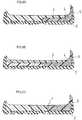
- FIGS. 8A to 8Ceach show a variation of the midsole of the embodiment.
- the lower midsole 4may only include the lateral portion 40 so that the midsole is formed by two layers of the lower midsole 4 and the upper midsole 3 on the lateral side OUT of the shoe.
- the midsoleOn the medial side IN of the shoe, the midsole may be formed by a single upper midsole 3 whose thickness is equal to the two layers.
- the upper midsole 3 with no hardness difference between the lateral side and the medial sidemay be arranged on the lower midsole 4 as shown in FIG. 8B .
- a high-hardness layer(the layer of the first hardness) may be provided on the lateral side OUT of the shoe, an intermediate-hardness layer (the layer of the second hardness) in the central portion, and a low-hardness layer (the layer of the third hardness) on the medial side IN.
- the hardness of the lateral portion 30 of the upper midsole 3 and the hardness of the medial portion 41 of the lower midsole 4may be generally equal to each other or may be different from each other.
- the medial portion 31 of the upper midsole 3may be set to a hardness generally equal to the hardness of the lateral portion 30 or that of the medial portion 41 of the lower midsole 4. That is, for example, the hardness of the medial portion and that of the lateral portion of the upper midsole 3 may be set to a certain hardness (a generally equal hardness).
- the lateral portion 40 of the lower midsole 4may be set to a hardness generally equal to the hardness of the medial portion 41 of the lower midsole 4 or that of the lateral portion 30 of the upper midsole 3.
- the present inventionis applicable to a shoe sole for court sports such as tennis and basketball.
Landscapes
- Health & Medical Sciences (AREA)
- General Health & Medical Sciences (AREA)
- Epidemiology (AREA)
- Public Health (AREA)
- Chemical & Material Sciences (AREA)
- Engineering & Computer Science (AREA)
- Materials Engineering (AREA)
- Physical Education & Sports Medicine (AREA)
- Footwear And Its Accessory, Manufacturing Method And Apparatuses (AREA)
Description
- The present invention relates to a structure of a shoe sole suitable for court sports such as tennis and basketball, for example.
- In court sports such as tennis and basketball, one is likely to suddenly change direction or stop while running, or use footwork in a lateral direction or a diagonally lateral direction. During such a footwork, a lateral shake (vibration) is likely to occur in which the foot is urged to move in the lateral-medial direction inside the shoe. In order to realize a stable footwork, it is necessary to prevent such a lateral shake.
- First Patent Document:
JP2007-135824A - Second Patent Document: Japanese Laid-Open Utility Model Publication No.
60-60905 - The first and second patent documents disclose increasing the hardness of a lateral portion of the midsole. Such a structure is likely to support the force acting upon the lateral side of the foot when changing directions in a court sport, etc.
- Also in the first patent document, the lateral portion of the midsole having a high hardness is rolled up, and such a roll-up portion serves to prevent a lateral shake.
- However, there is a hard outsole layer underneath, and if the upper-layer midsole apart from the bending neutral axis upon bending the sole alone is hard, the bending rigidity of the sole as a whole upon bending may be excessively high. As a result, the bendability of the sole may lower, thereby lowering the athletic functionality.
- Also, if the upper-layer midsole is hard, since the layer close to the foot sole is hard, the impact of landing is likely to occur on the foot sole.
- On the other hand, if the hardness of the roll-up portion decreases, the roll-up portion is likely to collapse and the roll-up portion is likely to be compressed by the resin stabilizer, whereby the lateral shake is likely to increase.
- Thus, an object of the first invention, related to a shoe sole, is to improve the lateral shake preventing function while preventing the lowering of the bendability of the sole and the lowering of the impact-absorbing property via the midsole in the vicinity of the foot sole.
- There are skeletal and muscular differences between legs and feet of men and those of women, and there is a large difference in the moment (torque) around the knee upon landing in tennis, or the like.
- If the moment around the knee is large, there is a large load on the knee.
- Thus, an object of the second invention is to provide tennis shoes for women, etc., with which the moment around the knee is reduced.
- The first invention in one aspect is a shoe sole including an
outsole 2 having a tread surface to be in contact with a road surface, and amidsole 1 arranged on theoutsole 2, wherein: - the
midsole 1 includes alower midsole 4 of a lower layer formed by a foamed body of a resin, and anupper midsole 3 of an upper layer formed by a foamed body of a resin and arranged on thelower midsole 4; - a lateral roll-up
portion 42 for supporting a lateral side of a foot from a side of the foot is formed integrally with thelower midsole 4; - a hardness of a
lateral portion 40 of thelower midsole 4 including the lateral roll-upportion 42 is a first hardness; - a hardness of a
medial portion 41 of thelower midsole 4 is a second hardness lower than the first hardness; - a hardness of a
lateral portion 30 of theupper midsole 3 is a third hardness lower than the first hardness; and - a part or a whole of the high-hardness lateral roll-up
portion 42 is protruding in an upward direction past theupper midsole 3 on a lateral side of theupper midsole 3 so that the lateral side of the foot is supported by the lateral roll-upportion 42 from the side of the foot without being supported by theupper midsole 3 from the side of the foot. - According to the first invention, the hardness of the
lateral portion 40 of thelower midsole 4 and the lateral roll-upportion 42 is higher than the hardness of themedial portion 41 and thelateral portion 30 of theupper midsole 3, and therefore the lateral roll-upportion 42 is supported by the hardlateral portion 40 of thelower midsole 4 and will unlikely collapse. The hard lateral roll-up portion 42 will unlikely be deformed in compressive deformation. Therefore, it is easy to prevent a lateral shake on the lateral side. - On the other hand, the hardness of the
lateral portion 30 of theupper midsole 3 is low as compared with the lateral roll-upportion 42. Therefore, thelateral portion 30 of theupper midsole 3 is likely to conform to the unevenness of the foot sole, and the bendability of the sole may be less likely to be detracted from. The impact-absorbing property is also less likely to be detracted from. - That is, even if there is a hard outsole layer underneath, the upper-layer midsole apart from the bending neutral axis upon bending the sole alone is not hard, and therefore the bending rigidity of the sole as a whole may not become excessively high. As a result, the bendability of the sole is unlikely to lower, and it may be possible to prevent the athletic functionality from lowering.
- Since the upper-layer midsole is not hard and therefore the layer close to the foot sole is soft, an impact upon landing will unlikely be imparted on the foot sole.
- Incidentally, a rubber outsole and a stabilizer made of a non-foamed body of a resin have been used to support the lateral side of the foot from the side. However, these members are harder and heavier than the foamed body of a resin of the midsole, and will therefore likely lead to a decrease in the athletic functionality such as foot bendability. In contrast, in the present shoe sole, the roll-up portion is formed by the midsole made of a foamed body of a resin, thereby realizing an appropriate hardness and a light weight, and therefore it will unlikely lead to a decrease in the bendability of the foot or a decrease in the athletic functionality.
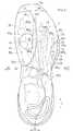
US 2010/287792 shows another prior art sole, with different midsole layers. FIG. 1 is an exploded perspective view showing a midsole according toEmbodiment 1 of the present invention.FIG. 2 is a perspective view of a midsole showing an upper midsole placed on a lower midsole.FIG. 3A is a longitudinal cross-sectional view of a shoe sole, andFIG. 3B is a lateral side view of the shoe sole.FIG. 4 is a plan view of the midsole.FIG. 5 is a plan view showing the relationship between the midsole and the foot bone structure.FIGS. 6A, 6B, 6C, and 6D are cross-sectional views taken along lines VIA-VIA, VIB-VIB, VIC-VIC and VID-VID ofFIG. 4 , respectively.FIGS. 7A, 7B, 7C, and 7D are schematic front views each showing an action of a subject, andFIGS. 7E and 7F are graphs showing the test results.FIGS. 8A, 8B, and 8C are cross-sectional views taken along line VIB-VIB ofFIG. 4 , each showing a variation of the midsole.- In the first invention, in a preferred example, the
lateral portion 30 of theupper midsole 3 supports a lower surface of a lateral side of a fore foot section of the foot; and
the high-hardness lateral roll-upportion 42 of thelower midsole 4 covers a lateral side surface of ahead 05 of a metatarsal bone of a fifth toe so as to support a lateral side of thehead 05 in the fore foot section. - Although a large force, which may cause a lateral shake, occurs at the
head 05 of the metatarsal bone of the fifth toe when making a turn, or the like, the lateral side of thehead 05 of the metatarsal bone of the fifth toe is supported by the high-hardness lateral roll-upportion 42 in the present embodiment. This will prevent the lateral shake of thehead 05 of the metatarsal bone of the fifth toe, i.e., the ball of the little toe. - More preferably, the high-hardness
lateral portion 40 of thelower midsole 4 covers a lower surface of the metatarsal bone of the fifth toe from thehead 05 to abottom 051 thereof; and
the low-hardnessmedial portion 41 of thelower midsole 4 covers a lower surface of a metatarsal bone of a first toe from ahead 01 to abottom 011 thereof and a lower surface of a proximal phalanx B31. - In such a case, the hardness of the
medial portion 41 of thelower midsole 4 is lower than the hardness of thelateral portion 40, and therefore the bendability of the sole may be less likely to be detracted from. Moreover, the impact-absorbing property is less likely to be detracted from. - Note that a bottom refers to a portion of each bone that is close to the posterior joint and that is slightly expanding to a greater thickness and it is referred to also as a proximal head. On the other hand, a head refers to a portion of each bone that is close to the anterior joint and that is slightly expanding to a greater thickness and it is referred to also as a distal head. A shaft refers to a portion between the bottom and the head, and the thickness thereof typically changes smoothly.
- More preferably, the
lateral portion 30 of theupper midsole 3 is narrowed in an area of the metatarsal bone of the fifth toe; and
the lateral roll-upportion 42 of thelower midsole 4 is rolled up in an upward direction in the area of the narrowedupper midsole 3. - In such a case, as the
lateral portion 30 of theupper midsole 3 is narrowed in the area of the metatarsal bone of the fifth toe, the lateral roll-upportion 42 rises from thelower midsole 4 without the volume of the lateral roll-upportion 42 of thelower midsole 4 decreasing and without the volume of the area extending from thelateral portion 40 of thelower midsole 4 to the lateral roll-upportion 42 decreasing. Therefore, with the hard lateral roll-upportion 42, it is possible to prevent the lateral shake of thehead 05 of the metatarsal bone of the fifth toe. - In another preferred embodiment, a hardness of a
medial portion 31 of theupper midsole 3 is a fourth hardness lower than the second hardness and the third hardness. - In such a case, since the
medial portion 31 of theupper midsole 3 is soft, the upper surface of the midsole will be tilted in a diagonally downward direction from the lateral side toward the medial side upon landing on one foot. Therefore, with tennis shoes for women, or the like, a moment which would be a burden on the knee is unlikely to occur upon landing on one foot. - More preferably, the
lateral portion 30 of theupper midsole 3 covers a lower surface of the metatarsal bone of the fifth toe from thehead 05 to thebottom 051 thereof; and
themedial portion 31 of theupper midsole 3 covers a lower surface of the metatarsal bone of the first toe from thehead 01 to thebottom 011 thereof and a lower surface of the proximal phalanx B31. - In such a case, it will be easy to prevent the occurrence of a moment which would be a burden on the knee.
- Preferably, the shoe sole further includes a
stabilizer 5, made of a non-foamed body of a resin, for example, arranged along a lateral side surface of the lateral roll-upportion 42 further on a lateral side of the lateral roll-upportion 42. - The
stabilizer 5 formed by a non-foamed body of a resin further enhances the lateral shake preventing function. - Preferably, the
outsole 2 is formed by a foamed body or a non-foamed body of a rubber and is rolled up in an upward direction further on a lateral side of the lateral roll-upportion 42. - The roll-up of the
outsole 2 will further enhance the lateral shake preventing function. - Prior to the detailed description of the second invention, a test conducted by the inventors of the second invention will be described.
- Using shoes of the same structure, male and female subjects performed a one-foot-landing action as seen when landing after a jump serve or when volleying, as shown in
FIGS. 7A to 7D , and the moments M (torques) occurring about the knee were measured. As a result, it was found that the moment M was greater for females than for males. - The moment M about the knee is calculated as the outer product between the ground reaction force vector F1, extending from the center of load indicated by a solid line in the figures, and the lower limb vector F2 indicated by a one-dot-chain line.
FIGS. 7E and 7F are bar graphs showing the magnitudes of the moments M for males and females, indicating that females have a greater moment M than males. - If a low-hardness midsole layer is inserted in the medial portion of the fore foot portion, the low-hardness midsole is compressed significantly, thereby tilting the sole toward the medial side, upon stepping in during the one-foot-landing action. When the sole is tilted toward the medial side, the ground reaction force vector F1 shown in
FIGS. 7A and 7C is similarly tilted, but the lower limb vector F2 hardly changes. Therefore, the ground reaction force vector F1 and the lower limb vector F2 will be of the same direction, and the moment M around the knee, which is calculated from the outer product therebetween, will be small. - Thus, the second invention in one aspect is a shoe sole including an
outsole 2 having a tread surface to be in contact with a ground upon landing, and amidsole 1 arranged on theoutsole 2, wherein: - the
midsole 1 includes alower midsole 4 of a lower layer formed by a foamed body of a resin for supporting a fore foot section of a foot, and anupper midsole 3 of an upper layer formed by a foamed body of a resin and arranged on thelower midsole 4 in the fore foot section; and - a hardness of a
medial portion 31 of a fore foot section of theupper midsole 3 is lower than a hardness of a fore foot section of thelower midsole 4, and the hardness of themedial portion 31 of the fore foot section of theupper midsole 3 is lower than a hardness of alateral portion 30 of the fore foot section of theupper midsole 3. - Now, as a shoe sole for correcting bowlegs, a shoe is known (
JP 2005-224335 A - Therefore, although this conventional technique may be helpful for correcting bowlegs through static deformation, one cannot expect an advantageous effect against the impact load such as those from landing on one foot in tennis, etc.
- In contrast, according to the second invention, the
medial portion 31 of the fore foot section of theupper midsole 3 has a low hardness, and themedial portion 31 of theupper midsole 3 is therefore compressed instantaneously by an impact load, thereby bringing the direction of the ground reaction force vector F1 and the direction of the lower limb vector F2 shown inFIGS. 7A and 7B closer to each other. Therefore, when the invention is applied to tennis shoes for women, the moment M occurring at the knee will be small. - On the other hand, if the hardness of the medial side of the fore foot section of the midsole is lowered without using an upper-lower two-layer structure, the amount of compression on the medial side of the fore foot section will be excessive, and a difference is therefore likely to occur between the direction of the ground reaction force vector F1 and the direction of the lower limb vector F2.
- Preferably, a low-hardness area of the
upper midsole 3 where the hardness is low is provided over an area extending from a shaft of a metatarsal bone of a first toe to a head of a proximal phalanx of the first toe. - By employing such an extent for the low-hardness area, the foot is likely to be tilted in the medial-side fore foot portion.
- Preferably, the
medial portion 31 of theupper midsole 3 is set to 40 degrees to 55 degrees in JIS-C hardness, and thelateral portion 30 of theupper midsole 3 is set to 50 degrees to 65 degrees in JIS-C hardness. - Note that the hardness difference between the
medial portion 31 of theupper midsole 3 and thelateral portion 30 of theupper midsole 3 is preferably about 5° to about 15° in JIS-C hardness. - With such a hardness difference therebetween, the tilt angle of the foot will be of an appropriate value.
- If the hardness is lower than such hardness settings, the entire sole is typically likely to sink, whereas if the hardness is higher than the hardness settings, it is typically difficult to achieve a level of flexibility that is needed for the sole.
- Preferably, the hardness of the
medial portion 31 of theupper midsole 3 is lower than a hardness of acentral portion upper midsole 3 or thelower midsole 4 in a medial and lateral direction;
a hardness of alateral portion upper midsole 3 orlower midsole 4 is higher than the hardness of thecentral portions upper midsole 3 or thelower midsole 4 in the medial and lateral direction. - If the
central portions - Thus, the second invention in another aspect is a shoe sole including an
outsole 2 having a tread surface to be in contact with a ground upon landing, and amidsole 1 arranged on theoutsole 2 and formed by a foamed body of a resin, themidsole 1 including: - a
lateral portion - a
medial portion - a
central portion lateral portion medial portion - the
lateral portion - the
central portion - the
medial portion
- the
- In the second invention, the
midsole 1 includes a layer of alower midsole 4 and a layer of anupper midsole 3 arranged on thelower midsole 4;
the layer of the first hardness is provided in one of theupper midsole 3 and thelower midsole 4 in thelateral portions
the layer of the third hardness is provided in one of theupper midsole 3 and thelower midsole 4 in themedial portions - The present invention will be understood more clearly from the following description of preferred embodiments taken in conjunction with the accompanying drawings. Note however that the embodiments and the drawings are merely illustrative, and should not be relied upon in defining the scope of the present invention. The scope of the present invention shall be defined only by the appended claims. In the accompanying drawings, like reference numerals denote like components throughout the plurality of figures.
- One embodiment of the present invention will now be described with reference to
FIGS. 1 to 6D . - As shown in
FIGS. 1 to 3A , the shoe sole is suitable for tennis shoes for women, for example, including anoutsole 2 having a tread surface to be in contact with the road surface, and amidsole 1 arranged on theoutsole 2. - The
midsole 1 is formed by, for example, a material suitable for impact absorption such as a foamed body of a resin such as EVA (ethylene-vinyl acetate copolymer). On the other hand, theoutsole 2 is formed by, for example, a material having a good abrasion resistance such as a foamed body or a non-foamed body of a rubber. - As shown in
FIG. 1 , themidsole 1 includes alower midsole 4 of the lower layer, and anupper midsole 3 of the upper layer arranged on thelower midsole 4 and supporting the fore foot section of the foot. A lateral roll-upportion 42 for supporting a lateral side of the foot from the side of the foot is formed integrally with thelower midsole 4. Thelower midsole 4 is provided over the entire length of the foot, whereas theupper midsole 3 is provided over a front-half area of the foot. - The hardness of a
lateral portion 40 of thelower midsole 4 including the lateral roll-upportion 42 is a first hardness. The hardness of amedial portion 41 of thelower midsole 4 is a second hardness lower than the first hardness. The hardness of alateral portion 30 of theupper midsole 3 is a third hardness lower than the first hardness. The hardness of amedial portion 31 of theupper midsole 3 is a fourth hardness lower than the second hardness and the third hardness. - More specifically, the
lateral portion 30 of theupper midsole 3 and themedial portion 41 of thelower midsole 4 are set to an intermediate hardness, e.g., about 50 degrees to about 65 degrees, and more preferably about 54 degrees to about 62 degrees, in JIS-C hardness. Note that the hardness of thelateral portion 30 of theupper midsole 3 and the hardness of themedial portion 41 of thelower midsole 4 may be about the same or may be slightly different from each other. - On the other hand, the
lateral portion 40 of thelower midsole 4 is set to a high hardness and is thick (coarsely) dotted inFIGS. 1 and4 . For example, the hardness is set to about 55 degrees to about 75 degrees, and more preferably about 61 degrees to about 69 degrees, in JIS-C hardness. - The
medial portion 31 of theupper midsole 3 is set to a low hardness and is densely dotted inFIGS. 1 and4 . For example, the hardness is set to about 40 degrees to about 55 degrees, and more preferably about 44 degrees to about 52 degrees, in JIS-C hardness. - Note that in
FIG. 4 , a portion of the area of thelower midsole 4 set to a high hardness over which theupper midsole 3 is arranged is dotted with an intermediate density between the coarse dotting and the dense dotting. - As shown in
FIGS. 1 and2 , a part or a whole of the high-hardness lateral roll-upportion 42 is protruding in an upward direction past theupper midsole 3 on a lateral side of theupper midsole 3 so that the lateral side of the foot is supported by the lateral roll-upportion 42 from the side of the foot without being supported by theupper midsole 3 from the side of the foot. - As shown in
FIG. 3B , when the shoe sole is viewed from the lateral side surface, the lateral roll-upportion 42 is protruding in the upward direction past theupper midsole 3, and there is a portion of thelateral portion 30 of theupper midsole 3 that is hidden by the lateral roll-upportion 42 and cannot be seen from the lateral side surface. That is, as seen from the lateral side surface, the lateral roll-upportion 42 of thelower midsole 4 supporting the side of the foot is located between thelateral portions upper midsole 3, and in other words, thelateral portions upper midsole 3 are exposed anterior and posterior of the lateral roll-upportion 42. - Note that the
lateral portion 30 of theupper midsole 3 may be rolled up slightly in the upward direction. - In the case of the present embodiment, the
lateral portion 30 of theupper midsole 3 ofFIG. 5 is hollowed out and narrowed in the area of thehead 05 of the metatarsal bone of the fifth toe. That is, in this area, the outer edge line of thelateral portion 40 of thelower midsole 4 is curved so as to protrude toward the lateral side, whereas the outer edge line of thelateral portion 30 of theupper midsole 3 is curved so as to protrude toward the medial side. - Specifically, the
lateral portion 30 of theupper midsole 3 is not covering at least one portion of an MP joint MP5 of the fifth toe, and thelateral portion 40 of thelower midsole 4 covers at least one portion of the MP joint MP5 of the fifth toe. - As shown in
FIGS. 1 and2 , the lateral roll-upportion 42 of thelower midsole 4 is rolled up in the upward direction in the narrowed area of theupper midsole 3. As thelateral portion 30 of theupper midsole 3 is narrowed as described above, abase portion 43 of the lateral roll-upportion 42 of thelower midsole 4 has a large thickness, as shown inFIG. 6B , thereby enhancing the lateral shake preventing effect by the lateral roll-upportion 42. - Specifically, as the
lateral portion 30 of theupper midsole 3 is narrowed, thelateral portion 30 does not extend to thebase portion 43, and the thickness of thebase portion 43 capable of supporting the load from above is larger than other areas of thelateral portion 40 of thelower midsole 4, thereby making it less likely that the lateral roll-upportion 42 collapses due to the force which laterally shakes the foot toward the lateral side. - The lateral roll-up
portion 42 protruding in the upward direction past theupper midsole 3 has ananterior end 42f and aposterior end 42b in the longitudinal direction Y. Theanterior end 42f is located anterior to the MP joint MP5 of the fifth toe and posterior to the tip of the fifth distal phalanx B15, whereas theposterior end 42b is located posterior to the MP joint MP5 of the fifth toe and anterior to thebottom 051 of the metatarsal bone B45 of the fifth toe. - The
lateral portion 30 of theupper midsole 3 supports the lower surface of the lateral side of the fore foot section of the foot. As shown inFIGS. 5 and6B , the high-hardness lateral roll-upportion 42 of thelower midsole 4 covers the lateral side surface of thehead 05 of the metatarsal bone of the fifth toe so as to support the lateral side of the head in the fore foot section. - At least a portion of the proximal phalanx B35 of the fifth toe and at least a portion of the metatarsal bone B45 of the fifth toe may be covered by the
lateral portion 40 of thelower midsole 4 from below. - Specifically, as shown in
FIG. 5 , thelateral portion 30 of theupper midsole 3 is not covering at least one portion of thehead 05 of the metatarsal bone and/or at least one portion of the MP joint MPs of the fifth toe, and these areas are covered from below by thelateral portion 40 of thelower midsole 4. - The
lateral portion 30 of theupper midsole 3 is at least covering a portion of the distal phalanx B15 of the fifth toe and a portion of the metatarsal bone B45 of the fifth toe. That is, in the vicinity of the MP joint MP5 of the fifth toe or thehead 05 of the metatarsal bone of the fifth toe, thelateral portion 40 of thelower midsole 4 is exposed, and at least the distal phalanx B15 of the fifth toe and a portion of the metatarsal bone B45 of the fifth toe are covered from below by thelateral portion 30 of theupper midsole 3 and thelateral portion 40 of thelower midsole 4. - As shown in
FIG. 5 , the high-hardness lateral portion 40 of thelower midsole 4 may be provided to extend along the lateral side of themidsole 1 to the posterior end of themidsole 1, covering an area posterior to the forth and fifth proximal phalanges B34 and B35. The high-hardness area may be arranged so as to bulge toward the central portion in the fore foot portion. - That is, the lateral line Ll, defining the high-hardness area, is curved so as to protrude toward the medial side in the fore foot portion, and is extending on the medial side of the MP joint MP5 of the fifth toe.
- On the other hand, the low-hardness
medial portion 31 of theupper midsole 3 may be arranged over an extent that covers the first and second metatarsal bones B41 and B42, the first and second proximal phalanges B31 and B32, the first distal phalanx B11 and the medial cuneiform bone, and may be covering the second middle phalanx B22. The low-hardness area may be arranged so as to bulge toward the central portion in the fore foot portion. - That is, the medial line Lm, defining the low-hardness area, is curved so as to protrude toward the lateral side in the fore foot portion, and is extending on the lateral side of the
head 01 of the metatarsal bone of the first toe. - Note that the lateral line Ll and the medial line Lm may come closest to each other in the vicinity of the MP joint MP3 of the third toe.
- In
FIG. 5 , the high-hardness lateral portion 40 of thelower midsole 4 covers the lower surface of thehead 05 to thebottom 051 of the metatarsal bone of the fifth toe. Themedial portion 41 of thelower midsole 4 set to the intermediate hardness covers the lower surface of thehead 01 to thebottom 011 of the metatarsal bone of the first toe and the proximal phalanx B31. - In
FIG. 5 , thelateral portion 30 of theupper midsole 3 set to the intermediate hardness covers the lower surface of thehead 05 to thebottom 051 of the metatarsal bone of the fifth toe. Themedial portion 31 of theupper midsole 3 set to the lower hardness covers the lower surface of thehead 01 to thebottom 011 of the metatarsal bone of the first toe and the proximal phalanx B31, and this low-hardness area is preferably provided at least over an area from the shaft of the first metatarsal bone B41 to the head of the first proximal phalanx B31. - As the areas are set as described above, the hardness of the
medial portion 31 of theupper midsole 3 is lower than the hardness of acentral portion upper midsole 3 or thelower midsole 4 in the medial-lateral direction, and the hardness of thelateral portion upper midsole 3 or thelower midsole 4 is higher than the hardness of thecentral portion upper midsole 3 or thelower midsole 4 in the medial-lateral direction. - That is, as shown in
FIG. 4 , in the fore foot portion, thelateral portion central portion medial portion - Specifically, as shown in
FIG. 4 , for example, in the area between the front line Lf and the back line Lb in the fore foot portion, the coarsely-dotted area on the lateral side of the lateral line Ll is the layer of the first hardness including the high-hardnesslower midsole 4 and the intermediate-hardnessupper midsole 3, whereas the densely-dotted area on the medial side of the medial line Lm is the layer of the third hardness including the intermediate-hardnesslower midsole 4 and the low-hardnessupper midsole 3. The undotted area between the first layer and the third layer is the layer of the second hardness including the intermediate-hardnesslower midsole 4 and the intermediate-hardnessupper midsole 3. - As shown in
FIGS. 4 and5 , the medial line Lm and the lateral line Ll are each bulging toward the center in the width direction X, and come closest to each other in the vicinity of the MP joint MP3 of the third toe. That is, in the fore foot portion, the width of the layer of the second hardness is smaller in the central portion thereof, and larger in the area anterior to the central portion and in the area posterior to the central portion, like an hourglass. - Note that the layer of the first hardness may be provided in either the
upper midsole 3 or thelower midsole 4 in thelateral portion upper midsole 3 or thelower midsole 4 in themedial portion - In
FIG. 1 , a throughhole 33 is formed in themedial portion 31 of theupper midsole 3. The throughhole 33 is provided at the position of theball 01 of the big toe as shown inFIG. 5 . As shown inFIG. 6B , the throughhole 33 is filled with a low-resilience part 35 of a foamed resin. The hardness of the low-resilience part 35 is even lower than the hardness of themedial portion 31 of theupper midsole 3, and is set to about 22 degrees to about 28 degrees in JIS-C hardness. - As shown in
FIG. 6B , thelower midsole 4 may be slightly bulging in the area where the throughhole 33 is provided, so that the thickness of the low-resilience part 35 is smaller than the thickness of theupper midsole 3. Then, it is possible to prevent the foot sole from sinking excessively in the area of the low-resilience part 35. - Note that the through
hole 33 and the low-resilience part 35 do not always need to be provided. - As shown in
FIGS. 3B ,6B and 6D , thestabilizer 5 for preventing a lateral shake may be provided. Thestabilizer 5 is made of a non-foamed body of a resin, and the like, and is arranged along the lateral side surface of the lateral roll-upportion 42 further on the lateral side of the lateral roll-upportion 42. The height of thestabilizer 5 is less than the height of the lateral roll-upportion 42. - As shown in
FIGS. 3B and6B , in the area of the lateral roll-upportion 42, a roll-upportion 22 of theoutsole 2 is provided further on the lateral side of thestabilizer 5. The roll-upportion 22 is rolled up in the upward direction further on the lateral side of the lateral roll-upportion 42, serving to prevent a lateral shake of theball 05 of the little toe. The height of the roll-upportion 22 is less than the height of the lateral roll-upportion 42. - That is, as shown in
FIG. 3B , when the shoe sole of the present invention is seen from the lateral side surface, in the area of the lateral roll-upportion 42 of thelower midsole 4, thestabilizer 5 is located at a level above the roll-upportion 22 of theoutsole 2, and the lateral roll-upportion 42 of thelower midsole 4 is located at a level above thestabilizer 5. - In the present shoe sole, the lateral roll-up
portion 42 is formed by thelower midsole 4 made of a foamed body of a resin, the height (level) of the rubber outsole and the height of the stabilizer made of a non-foamed body of a resin, and the like, are set to be lower than the lateral roll-upportion 42 in the area of the lateral roll-upportion 42. This realizes an appropriate hardness and a light weight of the shoe sole, and it will unlikely lead to a decrease in the bendability of the foot at the MP joint or a decrease in the athletic functionality. - The
upper midsole 3 and thelower midsole 4 of themidsole 1 may be separately molded in primary molding, and may then be bonded together or molded together in secondary molding. Alternatively, only the intermediate-hardness area FIG. 6B may be molded in primary molding, and the low-hardness and high-hardness areas may be molded with the intermediate-hardness areas, which have been molded in primary molding, inserted in the mold. - As shown in
FIGS. 3A and5 , the front line Lf and the back line Lb may define an area of thelower midsole 4 where theupper midsole 3 is arranged, and thelower midsole 4 may have steps along the front line Lf and the back line Lb so that thelower midsole 4 is dented down across the area. That is, thelower midsole 4 may be formed so as to have a depressed cross section. - Specifically, as shown in
FIG. 3A , in the vicinity of the back line Lb, the area posterior to the back line Lb may have an abruptly-increased thickness from the area anterior to the back line Lb. On the other hand, in the vicinity of the front line Lf, the area anterior to the front line Lf may have an abruptly-increased thickness from the area posterior to the front line Lf. - The
upper midsole 3 is fitted into the depressed portion of thelower midsole 4. That is, theupper midsole 3 does not extend to the anterior end 4e of thelower midsole 4, and the anterior end 4e of thelower midsole 4 is located anterior to theanterior end 3e of theupper midsole 3. FIGS. 8A to 8C each show a variation of the midsole of the embodiment.- As shown in
FIG. 8A , thelower midsole 4 may only include thelateral portion 40 so that the midsole is formed by two layers of thelower midsole 4 and theupper midsole 3 on the lateral side OUT of the shoe. On the medial side IN of the shoe, the midsole may be formed by a singleupper midsole 3 whose thickness is equal to the two layers. - For other than tennis shoes for women, e.g., for tennis shoes for men or shoes for other court sports, the
upper midsole 3 with no hardness difference between the lateral side and the medial side may be arranged on thelower midsole 4 as shown inFIG. 8B . - As shown in
FIG. 8C , a high-hardness layer (the layer of the first hardness) may be provided on the lateral side OUT of the shoe, an intermediate-hardness layer (the layer of the second hardness) in the central portion, and a low-hardness layer (the layer of the third hardness) on the medial side IN. - While preferred embodiments have been described above with reference to the drawings, various obvious changes and modifications will readily occur to those skilled in the art upon reading the present specification.
- For example, the hardness of the
lateral portion 30 of theupper midsole 3 and the hardness of themedial portion 41 of thelower midsole 4 may be generally equal to each other or may be different from each other. - For tennis shoes for men, the
medial portion 31 of theupper midsole 3 may be set to a hardness generally equal to the hardness of thelateral portion 30 or that of themedial portion 41 of thelower midsole 4. That is, for example, the hardness of the medial portion and that of the lateral portion of theupper midsole 3 may be set to a certain hardness (a generally equal hardness). - For tennis shoes for women, the
lateral portion 40 of thelower midsole 4 may be set to a hardness generally equal to the hardness of themedial portion 41 of thelower midsole 4 or that of thelateral portion 30 of theupper midsole 3. - Thus, such changes and modifications are deemed to fall within the scope of the present invention, which is defined by the appended claims.
- The present invention is applicable to a shoe sole for court sports such as tennis and basketball.
- 1: Midsole
- 2: Outsole 22: Roll-up portion
- 3: Upper midsole 30: Lateral portion 31: Medial portion 32: Roll-up portion 33: Through hole 34: Central portion 35:
Part 3e: Anterior end - 4: Lower midsole 40: Lateral portion 41: Medial portion 42: Lateral roll-up portion 43: Base portion 44: Central portion 4e: Anterior end
- 5: Stabilizer
- CL: Central axis
- F1: Ground reaction force vector F2: Lower limb vector
- Lf: Front line Lb: Back line Ll: Lateral line Lm: Medial line
- M: Moment
- IN: Medial side OUT: Lateral side
- Y: Longitudinal direction X: Width direction
Claims (10)
- A shoe sole comprising an outsole (2) having a tread surface to be in contact with a road surface, and a midsole (1) arranged on the outsole (2), wherein:the midsole (1) includes a lower midsole (4) of a lower layer formed by a foamed body of a resin, and an upper midsole (3) of an upper layer formed by a foamed body of a resin and arranged on the lower midsole (4);the upper midsole (3) of the upper layer includes: a lateral portion (30) that covers a lower surface of a metatarsal bone of a fifth toe from a head (05) to a bottom (051) thereof; and a medial portion (31) that covers a lower surface of a metatarsal bone of a first toe from a head (01) to a bottom (011) thereof and a lower surface of a proximal phalanx (B31);a lateral roll-up portion (42) for supporting a lateral side of a foot from a side of the foot and a base portion (43), which has a large thickness, of the lateral roll-up portion (42) of the lower midsole (4) are formed integrally with the lower midsole (4);a hardness of a lateral portion (40) of the lower midsole (4) including the lateral roll-up portion (42) and the base portion (43) that has a large thickness is a first hardness;a hardness of a medial portion (41) of the lower midsole (4) is a second hardness lower than the first hardness;a hardness of the lateral portion (30) of the upper midsole (3) is a third hardness lower than the first hardness;the lateral portion (30) of the upper midsole (3) is hollowed out and narrowed in the area of the head (05) of the metatarsal bone of the fifth toe;in the area of the head of the metatarsal bone of the fifth toe, an outer edge line of the lateral portion (30) of the upper midsole (3) is curved so as to protrude toward the medial side, and the lateral portion (30) of the upper midsole (3) does not cover at least one portion of an MP joint (MP5) of the fifth toe;in the area of the head (05) of the metatarsal bone of the fifth toe, an outer edge line of the lateral portion (40) of the lower midsole (4) is curved so as to protrude toward the lateral side, and the lateral portion (40) of the lower midsole (4) covers at least one portion of the MP joint (MP5) of the fifth toe; anda part or a whole of the high-hardness lateral roll-up portion (42) is protruding in an upward direction in the narrowed area of the upper midsole (3) past the upper midsole (3) on a lateral side of the upper midsole (3) so that the lateral side of the foot is supported by the lateral roll-up portion (42) from the side of the foot without being supported by the upper midsole (3) from the side of the foot.
- The shoe sole according to claim 1, wherein:the lateral portion (30) of the upper midsole (3) supports a lower surface of a lateral side of a fore foot section of the foot; andthe high-hardness lateral roll-up portion (42) of the lower midsole (4) covers a lateral side surface of a head (05) of a metatarsal bone of a fifth toe so as to support a lateral side of the head (05) in the fore foot section.
- The shoe sole according to claim 2, wherein:the high-hardness lateral portion (40) of the lower midsole (4) covers a lower surface of the metatarsal bone of the fifth toe from the head (05) to a bottom (051) thereof; andthe low-hardness medial portion (41) of the lower midsole (4) covers a lower surface of a metatarsal bone of a first toe from a head (01) to a bottom (011) thereof and a lower surface of a proximal phalanx (B31).
- The shoe sole according to claim 3, wherein a hardness of a medial portion (31) of the upper midsole (3) is a fourth hardness lower than the second hardness and the third hardness.
- The shoe sole according to claim 4, wherein:the lateral portion (30) of the upper midsole (3) covers the lower surface of the metatarsal bone of the fifth toe from the head (05) to the bottom (051) thereof; andthe medial portion (31) of the upper midsole (3) covers the lower surface of the metatarsal bone of the first toe from the head (01) to the bottom (011) thereof and a lower surface of the proximal phalanx (B31).
- The shoe sole according to any one of claims 1 to 5, further comprising a stabilizer (5) arranged along a lateral side surface of the lateral roll-up portion (42) further on a lateral side of the lateral roll-up portion (42).
- The shoe sole according to any one of claims 1 to 6, wherein the outsole (2) is formed by a foamed body or a non-foamed body of a rubber and is rolled up in the upward direction further on a lateral side of the lateral roll-up portion (42).
- A shoe sole according to claim 6, wherein the lateral roll-up portion (42) is protruding in the upward direction past the stabilizer (5).
- A shoe sole according to claim 7, wherein the lateral roll-up portion (42) is protruding in the upward direction past a rolled-up portion of the outsole (2).
- A shoe sole according to claim 1, wherein:the midsole (1) includes a lower midsole (4) of a lower layer formed by a foamed body of a resin for supporting a fore foot section of a foot, and an upper midsole (3) of an upper layer formed by a foamed body of a resin and arranged on the lower midsole (4) in the fore foot section; anda hardness of a medial portion (31) of a fore foot section of the upper midsole (3) is lower than a hardness of a fore foot section of the lower midsole (4), and the hardness of the medial portion (31) of the fore foot section of the upper midsole (3) is lower than a hardness of a lateral portion (30) of the fore foot section of the upper midsole (3).
Applications Claiming Priority (1)
| Application Number | Priority Date | Filing Date | Title |
|---|---|---|---|
| PCT/JP2012/061982WO2013168256A1 (en) | 2012-05-10 | 2012-05-10 | Sole provided with outer sole and midsole |
Publications (3)
| Publication Number | Publication Date |
|---|---|
| EP2848144A1 EP2848144A1 (en) | 2015-03-18 |
| EP2848144A4 EP2848144A4 (en) | 2016-06-15 |
| EP2848144B1true EP2848144B1 (en) | 2020-04-29 |
Family
ID=49550340
Family Applications (1)
| Application Number | Title | Priority Date | Filing Date |
|---|---|---|---|
| EP12876567.4AActiveEP2848144B1 (en) | 2012-05-10 | 2012-05-10 | Sole provided with outer sole and midsole |
Country Status (4)
| Country | Link |
|---|---|
| US (1) | US9775402B2 (en) |
| EP (1) | EP2848144B1 (en) |
| JP (1) | JP5465814B1 (en) |
| WO (1) | WO2013168256A1 (en) |
Families Citing this family (81)
| Publication number | Priority date | Publication date | Assignee | Title |
|---|---|---|---|---|
| US7874209B2 (en) | 2008-01-08 | 2011-01-25 | Northrop Grumman Guidance And Electronics Company, Inc. | Capacitive bulk acoustic wave disk gyroscopes with self-calibration |
| US20140059887A1 (en)* | 2011-09-08 | 2014-03-06 | Kevin B. Lawlor | Footwear support structures |
| DE102012206094B4 (en) | 2012-04-13 | 2019-12-05 | Adidas Ag | Soles for sports footwear, shoes and method of making a shoe sole |
| JP6342410B2 (en)* | 2012-11-08 | 2018-06-13 | ゲーファオベー・シューテック・アーゲーGvb Shoetech Ag | Shoe sole for pronation movement control |
| JP5442170B1 (en)* | 2013-01-24 | 2014-03-12 | 株式会社アシックス | Shoes and manufacturing method thereof |
| DE102013202306B4 (en) | 2013-02-13 | 2014-12-18 | Adidas Ag | Sole for a shoe |
| DE102013002519B4 (en) | 2013-02-13 | 2016-08-18 | Adidas Ag | Production method for damping elements for sportswear |
| US9610746B2 (en) | 2013-02-13 | 2017-04-04 | Adidas Ag | Methods for manufacturing cushioning elements for sports apparel |
| DE102013202291B4 (en) | 2013-02-13 | 2020-06-18 | Adidas Ag | Damping element for sportswear and shoes with such a damping element |
| US9930928B2 (en) | 2013-02-13 | 2018-04-03 | Adidas Ag | Sole for a shoe |
| EP2974614B1 (en) | 2013-03-15 | 2022-05-04 | ASICS Corporation | Midsole having a laminated structure |
| USD740004S1 (en) | 2013-04-12 | 2015-10-06 | Adidas Ag | Shoe |
| USD776410S1 (en) | 2013-04-12 | 2017-01-17 | Adidas Ag | Shoe |
| WO2014178137A1 (en) | 2013-05-01 | 2014-11-06 | 株式会社アシックス | Member for shoe sole |
| JP6055554B2 (en) | 2013-10-10 | 2016-12-27 | 株式会社アシックス | Shoe sole |
| US10159306B2 (en) | 2013-10-10 | 2018-12-25 | Asics Corporation | Shoe sole |
| DE102014215897B4 (en)* | 2014-08-11 | 2016-12-22 | Adidas Ag | adistar boost |
| DE102014216115B4 (en) | 2014-08-13 | 2022-03-31 | Adidas Ag | 3D elements cast together |
| JP6639078B2 (en)* | 2014-09-17 | 2020-02-05 | 株式会社アシックス | Shoes and soles suitable for people with O-legs |
| US9833038B2 (en)* | 2015-03-19 | 2017-12-05 | Nike, Inc. | Multi-density midsole and plate system |
| EP3275330B1 (en)* | 2015-03-23 | 2021-01-20 | ASICS Corporation | Shoe having stabilizer |
| JP6679363B2 (en)* | 2015-03-23 | 2020-04-15 | アディダス アーゲー | Soles and shoes |
| EP3552509B1 (en) | 2015-04-08 | 2021-03-17 | NIKE Innovate C.V. | Article with a cushioning assembly having inner and outer bladder elements and a reinforcement element and method of manufacturing an article |
| DE102015206486B4 (en) | 2015-04-10 | 2023-06-01 | Adidas Ag | Shoe, in particular sports shoe, and method for manufacturing the same |
| DE102015206900B4 (en) | 2015-04-16 | 2023-07-27 | Adidas Ag | sports shoe |
| EP3285607B1 (en) | 2015-04-21 | 2020-05-06 | Nike Innovate C.V. | Bladder element formed from three sheets and method of manufacturing a bladder element |
| DE102015209795B4 (en) | 2015-05-28 | 2024-03-21 | Adidas Ag | Ball and process for its production |
| JP2017029567A (en)* | 2015-08-05 | 2017-02-09 | 株式会社アシックス | Baseball shoes |
| USD783264S1 (en) | 2015-09-15 | 2017-04-11 | Adidas Ag | Shoe |
| EP3170419B1 (en) | 2015-10-08 | 2019-05-15 | ASICS Corporation | Shoe having upper and sole |
| US20170150778A1 (en)* | 2015-12-01 | 2017-06-01 | Nike, Inc. | Articles of Footwear and Sole Structures for Articles of Footwear |
| US10786040B2 (en)* | 2016-05-26 | 2020-09-29 | Nike, Inc. | Multi-durometer sole structure for an article of footwear |
| USD840136S1 (en) | 2016-08-03 | 2019-02-12 | Adidas Ag | Shoe midsole |
| USD840137S1 (en) | 2016-08-03 | 2019-02-12 | Adidas Ag | Shoe midsole |
| USD852475S1 (en) | 2016-08-17 | 2019-07-02 | Adidas Ag | Shoe |
| JP1582717S (en) | 2016-09-02 | 2017-07-31 | ||
| USD827266S1 (en)* | 2017-05-15 | 2018-09-04 | Nike, Inc. | Shoe midsole |
| KR102360537B1 (en) | 2017-05-23 | 2022-02-09 | 나이키 이노베이트 씨.브이. | Domed midsole with staged compressive stiffness |
| CN113876073A (en) | 2017-05-23 | 2022-01-04 | 耐克创新有限合伙公司 | Sole structure for an article of footwear with a contoured sole plate |
| KR102326973B1 (en) | 2017-05-23 | 2021-11-16 | 나이키 이노베이트 씨.브이. | Midsole with graded response |
| CN110662442B (en) | 2017-05-23 | 2021-08-24 | 耐克创新有限合伙公司 | Midsole system with graded response |
| USD899061S1 (en) | 2017-10-05 | 2020-10-20 | Adidas Ag | Shoe |
| US11583029B2 (en)* | 2018-01-22 | 2023-02-21 | Adidas Ag | Article of footwear with ribbed outsole and notched midsole |
| US20190225784A1 (en) | 2018-01-24 | 2019-07-25 | Nike, Inc. | Sole structures including polyolefin plates and articles of footwear formed therefrom |
| CN112135727B (en)* | 2018-05-08 | 2023-02-03 | 彪马欧洲股份公司 | Method for producing soles for shoes, in particular sports shoes |
| JP6975351B2 (en) | 2018-05-08 | 2021-12-01 | プーマ エス イーPuma Se | Sole of shoes, especially sports shoes |
| CN112074204B (en)* | 2018-05-18 | 2022-03-22 | 株式会社爱世克私 | Sole with layered midsole |
| US11006695B2 (en)* | 2018-05-31 | 2021-05-18 | Nike, Inc. | Footwear sole plate with forefoot through hole |
| EP3801108B1 (en) | 2018-05-31 | 2023-04-19 | NIKE Innovate C.V. | Footwear sole plate with non-parallel waves of varying thickness |
| CN112601472B (en)* | 2018-08-30 | 2022-06-17 | 株式会社爱世克私 | Parts for soles and shoes |
| WO2020106433A1 (en) | 2018-11-20 | 2020-05-28 | Nike Innovate C.V. | Footwear bladder system |
| TWI738103B (en)* | 2018-11-20 | 2021-09-01 | 荷蘭商耐克創新有限合夥公司 | Footwear bladder system |
| US12096823B1 (en)* | 2018-11-30 | 2024-09-24 | Under Armour, Inc. | Article of footwear |
| EP3797632A4 (en)* | 2018-12-11 | 2022-01-12 | ASICS Corporation | SHOE |
| US11864621B2 (en)* | 2018-12-31 | 2024-01-09 | Nike, Inc. | Sole structure having differing hardness regions |
| IT201900003549A1 (en)* | 2019-03-12 | 2019-06-12 | Roberto Montagna | Sole for footwear able to adapt to the shape or deformations of the user's foot. |
| DE102019204579B4 (en) | 2019-04-01 | 2022-10-06 | Adidas Ag | Recycling a shoe |
| FR3094872B1 (en)* | 2019-04-10 | 2021-03-19 | Salomon Sas | Sports shoe |
| US11122857B2 (en)* | 2019-06-12 | 2021-09-21 | Wolverine Outdoors, Inc. | Footwear cushioning sole assembly |
| WO2020261562A1 (en)* | 2019-06-28 | 2020-12-30 | 株式会社アシックス | Shoe |
| US11503875B2 (en)* | 2019-07-19 | 2022-11-22 | Nike, Inc. | Sole structures including polyolefin plates and articles of footwear formed therefrom |
| US11696620B2 (en) | 2019-07-19 | 2023-07-11 | Nike, Inc. | Articles of footwear including sole structures and rand |
| WO2021064987A1 (en)* | 2019-10-04 | 2021-04-08 | 株式会社アシックス | Shoe |
| WO2021117190A1 (en)* | 2019-12-12 | 2021-06-17 | 株式会社アシックス | Shoe sole and shoe comprising same |
| WO2021130904A1 (en) | 2019-12-25 | 2021-07-01 | 株式会社アシックス | Shoe and method for manufacturing shoe |
| US12317951B2 (en)* | 2020-01-03 | 2025-06-03 | Nike, Inc. | Sole structure for article of footwear |
| US11641906B2 (en) | 2020-02-27 | 2023-05-09 | Nike, Inc. | Medially-located lateral footwear stabilizer |
| WO2021242372A1 (en) | 2020-05-27 | 2021-12-02 | Nike Innovate C.V. | Footwear with fluid-filled bladder |
| KR102368391B1 (en)* | 2020-07-09 | 2022-03-02 | 주식회사 호진스포르티비 | Shoes having improved structure |
| JP7550556B2 (en)* | 2020-07-14 | 2024-09-13 | 株式会社アシックス | Soles and shoes |
| IT202000022600A1 (en)* | 2020-09-24 | 2022-03-24 | Vibram Spa | SOLE FOR SPORTS SHOES |
| EP4209145A4 (en)* | 2020-10-09 | 2023-10-04 | ASICS Corporation | Shoe sole and shoe comprising same |
| US12250989B2 (en)* | 2020-11-24 | 2025-03-18 | Nike, Inc. | Sole structure for article of footwear |
| EP4302630A4 (en)* | 2021-04-07 | 2024-04-24 | ASICS Corporation | Shoe sole and shoe |
| US12070096B2 (en) | 2021-06-28 | 2024-08-27 | Acushnet Company | Article of footwear with midsole having varying hardness |
| CN113498910A (en)* | 2021-07-29 | 2021-10-15 | 安踏(中国)有限公司 | Sport shoe and insole system thereof |
| WO2023034681A1 (en) | 2021-08-30 | 2023-03-09 | Nike, Inc. | Polyolefin-based resins, sole structures, and articles of footwear and sporting equipment formed therefrom |
| US12109775B2 (en) | 2021-12-22 | 2024-10-08 | Puma SE | Method for producing a sole of a shoe |
| CN120417805A (en)* | 2023-01-20 | 2025-08-01 | 普卢塔卢斯有限公司 | Support surface configured to improve foot alignment and method of forming the same |
| CN120390603A (en)* | 2023-01-20 | 2025-07-29 | 普卢塔卢斯有限公司 | Support surface and/or footwear configured to improve foot alignment and methods of forming the same |
| JP2024124926A (en)* | 2023-03-03 | 2024-09-13 | 株式会社アシックス | Sole and shoes equipped with same |
Family Cites Families (117)
| Publication number | Priority date | Publication date | Assignee | Title |
|---|---|---|---|---|
| JPS6060905A (en) | 1983-09-08 | 1985-04-08 | Nippon Peroxide Co Ltd | Manufacture of peroxide having superior disintegrability in water |
| JPS6060905U (en) | 1983-10-05 | 1985-04-27 | 西原 浩子 | Mid sole for athletic shoes |
| US5014706A (en)* | 1988-09-15 | 1991-05-14 | C. Nicolai Gmbh & Co. Kg | Orthotic insole with regions of different hardness |
| US5255451A (en)* | 1988-12-14 | 1993-10-26 | Avia Group International, Inc. | Insert member for use in an athletic shoe |
| US5367791A (en)* | 1993-02-04 | 1994-11-29 | Asahi, Inc. | Shoe sole |
| CA2186367A1 (en)* | 1994-04-15 | 1995-10-26 | Scott Kantro | Insole |
| US5718063A (en) | 1995-07-17 | 1998-02-17 | Asics Corporation | Midsole cushioning system |
| US5806210A (en)* | 1995-10-12 | 1998-09-15 | Akeva L.L.C. | Athletic shoe with improved heel structure |
| US5815950A (en)* | 1997-09-11 | 1998-10-06 | Wang; Sui-Mu | Air-cushioning sole insert lined with iridescent film |
| US6131311A (en)* | 1998-04-17 | 2000-10-17 | Payless Shoesource, Inc. | Insole insert for footwear |
| JP3258628B2 (en) | 1998-09-08 | 2002-02-18 | 株式会社アシックス | Athletic shoes |
| US6438870B2 (en) | 1998-11-05 | 2002-08-27 | Asics Corporation | Shoe sole with shock absorber structure |
| JP3396637B2 (en) | 1998-11-05 | 2003-04-14 | 株式会社アシックス | Support structure for shank on sole |
| JP2000152803A (en) | 1998-11-24 | 2000-06-06 | Asics Corp | Method for manufacturing anti-slip member |
| USD416381S (en) | 1998-12-14 | 1999-11-16 | Asics Corporation | Shoe cushioning system |
| US6467197B1 (en) | 1999-05-31 | 2002-10-22 | Asics Corp. | Shoe with arch reinforcement |
| US6374514B1 (en)* | 2000-03-16 | 2002-04-23 | Nike, Inc. | Footwear having a bladder with support members |
| JP3979765B2 (en) | 2000-05-15 | 2007-09-19 | 株式会社アシックス | Shoe sole shock absorber |
| US6598319B2 (en)* | 2001-01-17 | 2003-07-29 | Spenco Medical Corporation | Insole with rebounding and cushioning areas and adjustable arch support |
| US7444765B2 (en)* | 2001-02-21 | 2008-11-04 | Bivab, Llc | Foot guided shoe sole and footbed |
| JP4020664B2 (en)* | 2001-05-11 | 2007-12-12 | 株式会社アシックス | Midsole with buffer structure |
| AU2003203502B2 (en)* | 2002-04-10 | 2005-05-19 | Wolverine World Wide, Inc. | Footwear Sole |
| US6920707B1 (en)* | 2002-05-14 | 2005-07-26 | Nike, Inc. | System for modifying properties of an article of footwear |
| US7121020B1 (en)* | 2002-08-20 | 2006-10-17 | Dale Bathum | Running sandal |
| US20040098882A1 (en)* | 2002-11-26 | 2004-05-27 | Wei-Jei Tuan | Airbag buffer for footwear |
| JP3867054B2 (en) | 2003-02-10 | 2007-01-10 | 美津濃株式会社 | Sport shoe sole assembly |
| US20040181971A1 (en)* | 2003-03-21 | 2004-09-23 | E-Z Gard Industries, Inc.. | Footbed |
| JP3921453B2 (en) | 2003-04-04 | 2007-05-30 | 株式会社アシックス | Foot inclination measuring method, shoe or insole selection method, shoe or insole manufacturing method, and foot inclination measuring device |
| JP2004313443A (en) | 2003-04-16 | 2004-11-11 | Asics Corp | Shoe shape selection method, shoe shape selection system and shoe tip shape selection method |
| AU2004231386C1 (en) | 2003-04-24 | 2007-02-08 | Asics Corporation | Sports shoes having upper part with improved fitting property |
| USD518283S1 (en) | 2003-07-18 | 2006-04-04 | Asics Corporation | Shoe upper |
| USD501713S1 (en) | 2003-07-18 | 2005-02-15 | As/Cs Corporation | Shoe midsole |
| USD495860S1 (en) | 2003-07-18 | 2004-09-14 | Asics Corp | Shoe outsole |
| USD527516S1 (en) | 2003-07-18 | 2006-09-05 | Asics Corporation | Portion of a shoe upper |
| USD522229S1 (en) | 2003-07-18 | 2006-06-06 | Asics Corp. | Pair of shoe midsoles |
| USD496148S1 (en) | 2003-07-18 | 2004-09-21 | Asics Corporation | Pair of shoe outsoles |
| USD495859S1 (en) | 2003-08-20 | 2004-09-14 | Asics Corporation | Pair of shoe outsoles |
| USD501987S1 (en) | 2003-08-20 | 2005-02-22 | Asics Corporation | Shoe midsole |
| US7020988B1 (en)* | 2003-08-29 | 2006-04-04 | Pierre Andre Senizergues | Footwear with enhanced impact protection |
| DE112004001279B4 (en) | 2003-10-17 | 2012-11-08 | Asics Corp. | Shoe sole with reinforcing structure |
| US7020990B2 (en)* | 2004-01-13 | 2006-04-04 | M. Steven Khoury | Orthopedic device for distributing pressure |
| JP2005224335A (en) | 2004-02-12 | 2005-08-25 | Keiai Orthopedic Appliance Co Ltd | Shoe for correction |
| USD512818S1 (en) | 2004-05-27 | 2005-12-20 | Asics Corp. | Pair of shoe outsoles |
| USD512828S1 (en) | 2004-05-27 | 2005-12-20 | Asics Corporation | Pair of shoe midsoles |
| USD520732S1 (en) | 2004-05-27 | 2006-05-16 | Asics Corporation | Pair of shoe midsoles |
| USD512819S1 (en) | 2004-05-27 | 2005-12-20 | Asics Corporation | Pair of shoe outsoles |
| USD512827S1 (en) | 2004-05-27 | 2005-12-20 | Asics Corporation | Pair of shoe midsoles |
| USD512208S1 (en) | 2004-05-27 | 2005-12-06 | Asics Corporation | Pair of shoe outsoles |
| US7168187B2 (en)* | 2004-06-01 | 2007-01-30 | Wolverine World Wide, Inc. | Footwear construction and related method of manufacture |
| US7200955B2 (en)* | 2004-06-04 | 2007-04-10 | Nike, Inc. | Article of footwear incorporating a sole structure with compressible inserts |
| JP4452721B2 (en) | 2004-09-30 | 2010-04-21 | 株式会社アシックス | Shoe sole shock absorber |
| DE112005002327B4 (en) | 2004-09-30 | 2017-10-26 | Asics Corp. | Shock absorbing device for a shoe sole in a rear foot part |
| USD513115S1 (en) | 2004-11-15 | 2005-12-27 | Asics Corporation | Pair of shoe midsoles |
| USD509351S1 (en) | 2004-11-15 | 2005-09-13 | Asics Corporation | Shoe midsole |
| USD514286S1 (en) | 2004-11-15 | 2006-02-07 | Asics Corporation | Pair of shoe outsoles |
| US7383647B2 (en)* | 2005-03-10 | 2008-06-10 | New Balance Athletic Shoe, Inc | Mechanical cushioning system for footwear |
| USD575946S1 (en) | 2005-03-29 | 2008-09-02 | Asics Corporation | Pair of heels for shoe outsoles |
| US20060218819A1 (en)* | 2005-03-30 | 2006-10-05 | Chi-Kung Wu | Double-density elastic insert element for an outsole |
| USD553846S1 (en) | 2005-04-26 | 2007-10-30 | Asics Corporation | Shoe outsole and midsole |
| AU2006244974B2 (en) | 2005-05-10 | 2011-09-22 | Asics Corporation | Shoe sole component |
| WO2006120749A1 (en) | 2005-05-13 | 2006-11-16 | Asics Corporation | Damping device for shoe sole |
| WO2006125182A2 (en)* | 2005-05-19 | 2006-11-23 | Danner, Inc. | Footwear with a shank system |
| EP1898738A4 (en)* | 2005-07-01 | 2014-05-14 | Karhu Holding B V | Sole structure of a sports shoe |
| US7380353B2 (en)* | 2005-07-22 | 2008-06-03 | Ariat International, Inc. | Footwear sole with forefoot stabilizer, ribbed shank, and layered heel cushioning |
| US7484319B2 (en)* | 2005-08-12 | 2009-02-03 | Spenco Medical Corporation | Shoe insole |
| US7437838B2 (en)* | 2005-09-23 | 2008-10-21 | Srl, Inc. | Article of footwear |
| USD542522S1 (en) | 2005-10-11 | 2007-05-15 | Asics Corporation | Shoe midsole |
| WO2007046277A1 (en) | 2005-10-20 | 2007-04-26 | Asics Corporation | Sole with reinforcement structure |
| JP4851781B2 (en) | 2005-11-17 | 2012-01-11 | 株式会社アシックス | Shoe with lateral vibration suppression function |
| KR100575875B1 (en)* | 2005-12-28 | 2006-05-02 | 박종화 | Sole inclined upward and backward |
| JP4958505B2 (en) | 2006-02-10 | 2012-06-20 | ヨネックス株式会社 | Sports shoes |
| WO2007120632A2 (en)* | 2006-04-12 | 2007-10-25 | Deckers Outdoor Corporation | Chassis for footwear and method of making footwear |
| JP4886774B2 (en) | 2006-04-21 | 2012-02-29 | 株式会社アシックス | Sole with reinforced structure and sole with shock absorbing structure |
| US20070295451A1 (en)* | 2006-06-22 | 2007-12-27 | Wolverine World Wide,Inc. | Footwear sole construction |
| USD561434S1 (en) | 2006-08-01 | 2008-02-12 | Asics Corp. | Pair of shoe outsoles |
| EP2078468B1 (en) | 2006-10-19 | 2017-02-08 | ASICS Corporation | Sports shoe having upper portion with improved fitness |
| EP2074901B1 (en) | 2006-10-20 | 2013-01-09 | ASICS Corporation | Structure for front foot portion of shoe sole |
| USD575486S1 (en) | 2007-05-11 | 2008-08-26 | Asics Corporation | Pair of shoe outsoles |
| CA2688794C (en)* | 2007-05-18 | 2013-06-25 | The North Face Apparel Corp. | Supporting plate apparatus for shoes |
| US8819961B1 (en)* | 2007-06-29 | 2014-09-02 | Frampton E. Ellis | Sets of orthotic or other footwear inserts and/or soles with progressive corrections |
| USD571090S1 (en) | 2007-07-17 | 2008-06-17 | Asics Corporation | Pair of shoe outsoles |
| US8056261B2 (en)* | 2007-07-20 | 2011-11-15 | Wolverine World Wide, Inc. | Footwear sole construction |
| US7954257B2 (en)* | 2007-11-07 | 2011-06-07 | Wolverine World Wide, Inc. | Footwear construction and related method of manufacture |
| WO2009106076A1 (en)* | 2008-02-27 | 2009-09-03 | Ecco Sko A/S | Sole for a shoe, in particular for a running shoe |
| EP2247212B1 (en)* | 2008-02-27 | 2017-10-25 | Ecco Sko A/S | Midsole for a running shoe |
| US8453355B2 (en)* | 2008-05-20 | 2013-06-04 | Cleatskins, Llc | Cover for cleated shoes |
| WO2010003414A1 (en)* | 2008-07-05 | 2010-01-14 | Ecco Sko A/S | Sole for a shoe, in particular for a running shoe |
| US9003679B2 (en)* | 2008-08-06 | 2015-04-14 | Nike, Inc. | Customization of inner sole board |
| KR20110082143A (en)* | 2008-09-22 | 2011-07-18 | 에스알홀딩스, 엘엘씨 | Footwear article |
| AU2008362408B2 (en)* | 2008-09-30 | 2013-06-06 | Asics Corporation | Shoe sole of athletic shoe with high running efficiency |
| KR101598130B1 (en)* | 2009-05-27 | 2016-02-26 | 가부시키가이샤아식스 | Shoe sole of shoe suitable for training |
| US8650775B2 (en)* | 2009-06-25 | 2014-02-18 | Nike, Inc. | Article of footwear having a sole structure with perimeter and central elements |
| US20110099845A1 (en)* | 2009-11-03 | 2011-05-05 | Miller Michael J | Customized footwear and methods for manufacturing |
| AU2009355126B2 (en) | 2009-11-16 | 2013-09-05 | Asics Corporation | Shoe with improved heel fit performance |
| US20110179679A1 (en)* | 2010-01-28 | 2011-07-28 | Skechers U.S.A., Inc. Ii | Shoe midsole |
| WO2011129017A1 (en) | 2010-04-16 | 2011-10-20 | 株式会社アシックス | Structure for forefoot section of shoe upper part |
| USD659371S1 (en) | 2010-04-30 | 2012-05-15 | Asics Corporation | Shoe upper |
| USD650566S1 (en) | 2010-05-07 | 2011-12-20 | Asics Corporation | Shoe |
| KR101164463B1 (en)* | 2010-07-12 | 2012-07-20 | 박수현 | A footwear having a function of air circulation |
| UA108665C2 (en)* | 2010-09-03 | 2015-05-25 | Sole ventilation element, and also soled sole and waterproof, breathable shoe item containing it | |
| US20120151793A1 (en)* | 2010-12-21 | 2012-06-21 | Lin Kwang-Huo | Foamed shoe sole |
| KR20130133260A (en)* | 2010-12-28 | 2013-12-06 | 수퍼핏 월드와이드, 인크. | Footwear with orthotic midsole |
| CA2829125A1 (en)* | 2011-03-18 | 2012-09-27 | Columbia Sportswear North America, Inc. | High-stability multi-density midsole |
| DE102011051444A1 (en)* | 2011-06-29 | 2013-01-03 | Deeluxe Sportartikel Handels Gmbh | Sole for a shoe, especially a running shoe |
| FR2978019B1 (en)* | 2011-07-20 | 2014-08-15 | Salomon Sas | IMPROVED SHOE SHOE |
| JP5749358B2 (en) | 2012-01-18 | 2015-07-15 | 株式会社アシックス | Foam sole and shoes |
| JP5190565B1 (en) | 2012-05-10 | 2013-04-24 | 株式会社アシックス | Shoe sole with slant groove |
| US10113045B2 (en) | 2012-05-31 | 2018-10-30 | Asics Corporation | Molded foam article, foamed sole, and shoe |
| US10849387B2 (en)* | 2012-09-20 | 2020-12-01 | Nike, Inc. | Sole structures and articles of footwear having plate moderated fluid-filled bladders and/or foam type impact force attenuation members |
| US9456658B2 (en)* | 2012-09-20 | 2016-10-04 | Nike, Inc. | Sole structures and articles of footwear having plate moderated fluid-filled bladders and/or foam type impact force attenuation members |
| US10856612B2 (en)* | 2012-09-20 | 2020-12-08 | Nike, Inc. | Sole structures and articles of footwear having plate moderated fluid-filled bladders and/or foam type impact force attenuation members |
| WO2014068635A1 (en) | 2012-10-29 | 2014-05-08 | 株式会社アシックス | Shoe sole designed for windlass mechanism |
| WO2014068169A1 (en)* | 2012-11-05 | 2014-05-08 | Feet2 Oy | Midsole structure for a sports shoe and sports shoe |
| US20140173945A1 (en)* | 2012-12-24 | 2014-06-26 | Kou-Bin LIN | Footbed and method for making the same |
| US9301566B2 (en)* | 2013-03-15 | 2016-04-05 | Nike, Inc. | Sole structures and articles of footwear having a lightweight midsole member with protective elements |
| USD734928S1 (en) | 2013-03-28 | 2015-07-28 | Asics Corporation | Footwear sole |
| USD734927S1 (en) | 2013-03-28 | 2015-07-28 | Asics Corporation | Footwear sole |
- 2012
- 2012-05-10EPEP12876567.4Apatent/EP2848144B1/enactiveActive
- 2012-05-10WOPCT/JP2012/061982patent/WO2013168256A1/enactiveApplication Filing
- 2012-05-10USUS14/398,429patent/US9775402B2/enactiveActive
- 2012-05-10JPJP2013540137Apatent/JP5465814B1/enactiveActive
Non-Patent Citations (1)
| Title |
|---|
| None* |
Also Published As
| Publication number | Publication date |
|---|---|
| US9775402B2 (en) | 2017-10-03 |
| EP2848144A4 (en) | 2016-06-15 |
| JPWO2013168256A1 (en) | 2015-12-24 |
| US20150082668A1 (en) | 2015-03-26 |
| JP5465814B1 (en) | 2014-04-09 |
| WO2013168256A1 (en) | 2013-11-14 |
| EP2848144A1 (en) | 2015-03-18 |
Similar Documents
| Publication | Publication Date | Title |
|---|---|---|
| EP2848144B1 (en) | Sole provided with outer sole and midsole | |
| US11700911B2 (en) | Shoe sole including laminate-structured midsole | |
| US11825903B2 (en) | Shoe sole and shoe | |
| US9210967B2 (en) | Sole structure with traction elements | |
| EP3302142B1 (en) | Shoe soles for midfoot impact region | |
| EP3275330B1 (en) | Shoe having stabilizer | |
| KR20180004178A (en) | Outlined Shoe Insole | |
| US20090151194A1 (en) | Shoe Insole | |
| KR20180004105A (en) | Outlined Shoe Insole | |
| EP3629809B1 (en) | Article of footwear with auxetic sole structure having a filled auxetic aperture | |
| JP7261817B2 (en) | shoes | |
| US20170055635A1 (en) | Midsole for dispersing pressure of midfoot and metatarsal bones and shoe having same | |
| JP6639078B2 (en) | Shoes and soles suitable for people with O-legs | |
| JP4709085B2 (en) | Insole and insole | |
| JP2023505321A (en) | Shoes with a sole that achieves dynamic plantar arch support | |
| JP2001299404A (en) | Shoe sole | |
| US20120079740A1 (en) | Basketball Shoe Sole | |
| JP2023505319A (en) | Shoes with soles that provide dynamic heel support | |
| US12201181B2 (en) | Shoe sole and shoe | |
| EP3056105A1 (en) | Exercise shoe sole | |
| JP2011045481A (en) | Shoe with heel |
Legal Events
| Date | Code | Title | Description |
|---|---|---|---|
| PUAI | Public reference made under article 153(3) epc to a published international application that has entered the european phase | Free format text:ORIGINAL CODE: 0009012 | |
| 17P | Request for examination filed | Effective date:20141208 | |
| AK | Designated contracting states | Kind code of ref document:A1 Designated state(s):AL AT BE BG CH CY CZ DE DK EE ES FI FR GB GR HR HU IE IS IT LI LT LU LV MC MK MT NL NO PL PT RO RS SE SI SK SM TR | |
| AX | Request for extension of the european patent | Extension state:BA ME | |
| DAX | Request for extension of the european patent (deleted) | ||
| RIC1 | Information provided on ipc code assigned before grant | Ipc:A43B 13/16 20060101AFI20160118BHEP Ipc:A43B 13/04 20060101ALI20160118BHEP Ipc:A43B 5/10 20060101ALI20160118BHEP | |
| RA4 | Supplementary search report drawn up and despatched (corrected) | Effective date:20160517 | |
| RIC1 | Information provided on ipc code assigned before grant | Ipc:A43B 5/10 20060101ALI20160510BHEP Ipc:A43B 13/04 20060101ALI20160510BHEP Ipc:A43B 13/16 20060101AFI20160510BHEP | |
| STAA | Information on the status of an ep patent application or granted ep patent | Free format text:STATUS: EXAMINATION IS IN PROGRESS | |
| 17Q | First examination report despatched | Effective date:20181105 | |
| GRAP | Despatch of communication of intention to grant a patent | Free format text:ORIGINAL CODE: EPIDOSNIGR1 | |
| STAA | Information on the status of an ep patent application or granted ep patent | Free format text:STATUS: GRANT OF PATENT IS INTENDED | |
| INTG | Intention to grant announced | Effective date:20191104 | |
| GRAS | Grant fee paid | Free format text:ORIGINAL CODE: EPIDOSNIGR3 | |
| GRAA | (expected) grant | Free format text:ORIGINAL CODE: 0009210 | |
| STAA | Information on the status of an ep patent application or granted ep patent | Free format text:STATUS: THE PATENT HAS BEEN GRANTED | |
| AK | Designated contracting states | Kind code of ref document:B1 Designated state(s):AL AT BE BG CH CY CZ DE DK EE ES FI FR GB GR HR HU IE IS IT LI LT LU LV MC MK MT NL NO PL PT RO RS SE SI SK SM TR | |
| REG | Reference to a national code | Ref country code:GB Ref legal event code:FG4D | |
| REG | Reference to a national code | Ref country code:CH Ref legal event code:EP | |
| REG | Reference to a national code | Ref country code:AT Ref legal event code:REF Ref document number:1262004 Country of ref document:AT Kind code of ref document:T Effective date:20200515 | |
| REG | Reference to a national code | Ref country code:DE Ref legal event code:R096 Ref document number:602012069766 Country of ref document:DE | |
| REG | Reference to a national code | Ref country code:IE Ref legal event code:FG4D | |
| REG | Reference to a national code | Ref country code:NL Ref legal event code:MP Effective date:20200429 | |
| REG | Reference to a national code | Ref country code:LT Ref legal event code:MG4D | |
| PG25 | Lapsed in a contracting state [announced via postgrant information from national office to epo] | Ref country code:SE Free format text:LAPSE BECAUSE OF FAILURE TO SUBMIT A TRANSLATION OF THE DESCRIPTION OR TO PAY THE FEE WITHIN THE PRESCRIBED TIME-LIMIT Effective date:20200429 Ref country code:GR Free format text:LAPSE BECAUSE OF FAILURE TO SUBMIT A TRANSLATION OF THE DESCRIPTION OR TO PAY THE FEE WITHIN THE PRESCRIBED TIME-LIMIT Effective date:20200730 Ref country code:FI Free format text:LAPSE BECAUSE OF FAILURE TO SUBMIT A TRANSLATION OF THE DESCRIPTION OR TO PAY THE FEE WITHIN THE PRESCRIBED TIME-LIMIT Effective date:20200429 Ref country code:NO Free format text:LAPSE BECAUSE OF FAILURE TO SUBMIT A TRANSLATION OF THE DESCRIPTION OR TO PAY THE FEE WITHIN THE PRESCRIBED TIME-LIMIT Effective date:20200729 Ref country code:IS Free format text:LAPSE BECAUSE OF FAILURE TO SUBMIT A TRANSLATION OF THE DESCRIPTION OR TO PAY THE FEE WITHIN THE PRESCRIBED TIME-LIMIT Effective date:20200829 Ref country code:PT Free format text:LAPSE BECAUSE OF FAILURE TO SUBMIT A TRANSLATION OF THE DESCRIPTION OR TO PAY THE FEE WITHIN THE PRESCRIBED TIME-LIMIT Effective date:20200831 Ref country code:LT Free format text:LAPSE BECAUSE OF FAILURE TO SUBMIT A TRANSLATION OF THE DESCRIPTION OR TO PAY THE FEE WITHIN THE PRESCRIBED TIME-LIMIT Effective date:20200429 | |
| REG | Reference to a national code | Ref country code:AT Ref legal event code:MK05 Ref document number:1262004 Country of ref document:AT Kind code of ref document:T Effective date:20200429 | |
| PG25 | Lapsed in a contracting state [announced via postgrant information from national office to epo] | Ref country code:LV Free format text:LAPSE BECAUSE OF FAILURE TO SUBMIT A TRANSLATION OF THE DESCRIPTION OR TO PAY THE FEE WITHIN THE PRESCRIBED TIME-LIMIT Effective date:20200429 Ref country code:RS Free format text:LAPSE BECAUSE OF FAILURE TO SUBMIT A TRANSLATION OF THE DESCRIPTION OR TO PAY THE FEE WITHIN THE PRESCRIBED TIME-LIMIT Effective date:20200429 Ref country code:BG Free format text:LAPSE BECAUSE OF FAILURE TO SUBMIT A TRANSLATION OF THE DESCRIPTION OR TO PAY THE FEE WITHIN THE PRESCRIBED TIME-LIMIT Effective date:20200729 Ref country code:HR Free format text:LAPSE BECAUSE OF FAILURE TO SUBMIT A TRANSLATION OF THE DESCRIPTION OR TO PAY THE FEE WITHIN THE PRESCRIBED TIME-LIMIT Effective date:20200429 | |
| PG25 | Lapsed in a contracting state [announced via postgrant information from national office to epo] | Ref country code:NL Free format text:LAPSE BECAUSE OF FAILURE TO SUBMIT A TRANSLATION OF THE DESCRIPTION OR TO PAY THE FEE WITHIN THE PRESCRIBED TIME-LIMIT Effective date:20200429 Ref country code:AL Free format text:LAPSE BECAUSE OF FAILURE TO SUBMIT A TRANSLATION OF THE DESCRIPTION OR TO PAY THE FEE WITHIN THE PRESCRIBED TIME-LIMIT Effective date:20200429 | |
| PG25 | Lapsed in a contracting state [announced via postgrant information from national office to epo] | Ref country code:IT Free format text:LAPSE BECAUSE OF FAILURE TO SUBMIT A TRANSLATION OF THE DESCRIPTION OR TO PAY THE FEE WITHIN THE PRESCRIBED TIME-LIMIT Effective date:20200429 Ref country code:RO Free format text:LAPSE BECAUSE OF FAILURE TO SUBMIT A TRANSLATION OF THE DESCRIPTION OR TO PAY THE FEE WITHIN THE PRESCRIBED TIME-LIMIT Effective date:20200429 Ref country code:CZ Free format text:LAPSE BECAUSE OF FAILURE TO SUBMIT A TRANSLATION OF THE DESCRIPTION OR TO PAY THE FEE WITHIN THE PRESCRIBED TIME-LIMIT Effective date:20200429 Ref country code:CH Free format text:LAPSE BECAUSE OF NON-PAYMENT OF DUE FEES Effective date:20200531 Ref country code:SM Free format text:LAPSE BECAUSE OF FAILURE TO SUBMIT A TRANSLATION OF THE DESCRIPTION OR TO PAY THE FEE WITHIN THE PRESCRIBED TIME-LIMIT Effective date:20200429 Ref country code:EE Free format text:LAPSE BECAUSE OF FAILURE TO SUBMIT A TRANSLATION OF THE DESCRIPTION OR TO PAY THE FEE WITHIN THE PRESCRIBED TIME-LIMIT Effective date:20200429 Ref country code:AT Free format text:LAPSE BECAUSE OF FAILURE TO SUBMIT A TRANSLATION OF THE DESCRIPTION OR TO PAY THE FEE WITHIN THE PRESCRIBED TIME-LIMIT Effective date:20200429 Ref country code:MC Free format text:LAPSE BECAUSE OF FAILURE TO SUBMIT A TRANSLATION OF THE DESCRIPTION OR TO PAY THE FEE WITHIN THE PRESCRIBED TIME-LIMIT Effective date:20200429 Ref country code:DK Free format text:LAPSE BECAUSE OF FAILURE TO SUBMIT A TRANSLATION OF THE DESCRIPTION OR TO PAY THE FEE WITHIN THE PRESCRIBED TIME-LIMIT Effective date:20200429 Ref country code:ES Free format text:LAPSE BECAUSE OF FAILURE TO SUBMIT A TRANSLATION OF THE DESCRIPTION OR TO PAY THE FEE WITHIN THE PRESCRIBED TIME-LIMIT Effective date:20200429 Ref country code:LI Free format text:LAPSE BECAUSE OF NON-PAYMENT OF DUE FEES Effective date:20200531 | |
| REG | Reference to a national code | Ref country code:DE Ref legal event code:R097 Ref document number:602012069766 Country of ref document:DE | |
| PG25 | Lapsed in a contracting state [announced via postgrant information from national office to epo] | Ref country code:PL Free format text:LAPSE BECAUSE OF FAILURE TO SUBMIT A TRANSLATION OF THE DESCRIPTION OR TO PAY THE FEE WITHIN THE PRESCRIBED TIME-LIMIT Effective date:20200429 Ref country code:SK Free format text:LAPSE BECAUSE OF FAILURE TO SUBMIT A TRANSLATION OF THE DESCRIPTION OR TO PAY THE FEE WITHIN THE PRESCRIBED TIME-LIMIT Effective date:20200429 | |
| PLBE | No opposition filed within time limit | Free format text:ORIGINAL CODE: 0009261 | |
| STAA | Information on the status of an ep patent application or granted ep patent | Free format text:STATUS: NO OPPOSITION FILED WITHIN TIME LIMIT | |
| REG | Reference to a national code | Ref country code:BE Ref legal event code:MM Effective date:20200531 | |
| PG25 | Lapsed in a contracting state [announced via postgrant information from national office to epo] | Ref country code:LU Free format text:LAPSE BECAUSE OF NON-PAYMENT OF DUE FEES Effective date:20200510 | |
| 26N | No opposition filed | Effective date:20210201 | |
| PG25 | Lapsed in a contracting state [announced via postgrant information from national office to epo] | Ref country code:IE Free format text:LAPSE BECAUSE OF NON-PAYMENT OF DUE FEES Effective date:20200510 | |
| PG25 | Lapsed in a contracting state [announced via postgrant information from national office to epo] | Ref country code:BE Free format text:LAPSE BECAUSE OF NON-PAYMENT OF DUE FEES Effective date:20200531 Ref country code:SI Free format text:LAPSE BECAUSE OF FAILURE TO SUBMIT A TRANSLATION OF THE DESCRIPTION OR TO PAY THE FEE WITHIN THE PRESCRIBED TIME-LIMIT Effective date:20200429 | |
| PG25 | Lapsed in a contracting state [announced via postgrant information from national office to epo] | Ref country code:TR Free format text:LAPSE BECAUSE OF FAILURE TO SUBMIT A TRANSLATION OF THE DESCRIPTION OR TO PAY THE FEE WITHIN THE PRESCRIBED TIME-LIMIT Effective date:20200429 Ref country code:MT Free format text:LAPSE BECAUSE OF FAILURE TO SUBMIT A TRANSLATION OF THE DESCRIPTION OR TO PAY THE FEE WITHIN THE PRESCRIBED TIME-LIMIT Effective date:20200429 Ref country code:CY Free format text:LAPSE BECAUSE OF FAILURE TO SUBMIT A TRANSLATION OF THE DESCRIPTION OR TO PAY THE FEE WITHIN THE PRESCRIBED TIME-LIMIT Effective date:20200429 | |
| PG25 | Lapsed in a contracting state [announced via postgrant information from national office to epo] | Ref country code:MK Free format text:LAPSE BECAUSE OF FAILURE TO SUBMIT A TRANSLATION OF THE DESCRIPTION OR TO PAY THE FEE WITHIN THE PRESCRIBED TIME-LIMIT Effective date:20200429 | |
| REG | Reference to a national code | Ref country code:FR Ref legal event code:PLFP Year of fee payment:12 | |
| PGFP | Annual fee paid to national office [announced via postgrant information from national office to epo] | Ref country code:GB Payment date:20250327 Year of fee payment:14 | |
| PGFP | Annual fee paid to national office [announced via postgrant information from national office to epo] | Ref country code:DE Payment date:20250402 Year of fee payment:14 | |
| PGFP | Annual fee paid to national office [announced via postgrant information from national office to epo] | Ref country code:FR Payment date:20250401 Year of fee payment:14 |