EP2847535B1 - Heat storage tank with improved thermal stratification - Google Patents
Heat storage tank with improved thermal stratificationDownload PDFInfo
- Publication number
- EP2847535B1 EP2847535B1EP13724192.3AEP13724192AEP2847535B1EP 2847535 B1EP2847535 B1EP 2847535B1EP 13724192 AEP13724192 AEP 13724192AEP 2847535 B1EP2847535 B1EP 2847535B1
- Authority
- EP
- European Patent Office
- Prior art keywords
- tank
- tank according
- liquid
- heat storage
- solar power
- Prior art date
- Legal status (The legal status is an assumption and is not a legal conclusion. Google has not performed a legal analysis and makes no representation as to the accuracy of the status listed.)
- Active
Links
Images


Classifications
- F—MECHANICAL ENGINEERING; LIGHTING; HEATING; WEAPONS; BLASTING
- F24—HEATING; RANGES; VENTILATING
- F24S—SOLAR HEAT COLLECTORS; SOLAR HEAT SYSTEMS
- F24S60/00—Arrangements for storing heat collected by solar heat collectors
- F—MECHANICAL ENGINEERING; LIGHTING; HEATING; WEAPONS; BLASTING
- F28—HEAT EXCHANGE IN GENERAL
- F28D—HEAT-EXCHANGE APPARATUS, NOT PROVIDED FOR IN ANOTHER SUBCLASS, IN WHICH THE HEAT-EXCHANGE MEDIA DO NOT COME INTO DIRECT CONTACT
- F28D20/00—Heat storage plants or apparatus in general; Regenerative heat-exchange apparatus not covered by groups F28D17/00 or F28D19/00
- F28D20/0034—Heat storage plants or apparatus in general; Regenerative heat-exchange apparatus not covered by groups F28D17/00 or F28D19/00 using liquid heat storage material
- F28D20/0039—Heat storage plants or apparatus in general; Regenerative heat-exchange apparatus not covered by groups F28D17/00 or F28D19/00 using liquid heat storage material with stratification of the heat storage material
- F—MECHANICAL ENGINEERING; LIGHTING; HEATING; WEAPONS; BLASTING
- F28—HEAT EXCHANGE IN GENERAL
- F28D—HEAT-EXCHANGE APPARATUS, NOT PROVIDED FOR IN ANOTHER SUBCLASS, IN WHICH THE HEAT-EXCHANGE MEDIA DO NOT COME INTO DIRECT CONTACT
- F28D20/00—Heat storage plants or apparatus in general; Regenerative heat-exchange apparatus not covered by groups F28D17/00 or F28D19/00
- F28D20/0056—Heat storage plants or apparatus in general; Regenerative heat-exchange apparatus not covered by groups F28D17/00 or F28D19/00 using solid heat storage material
- Y—GENERAL TAGGING OF NEW TECHNOLOGICAL DEVELOPMENTS; GENERAL TAGGING OF CROSS-SECTIONAL TECHNOLOGIES SPANNING OVER SEVERAL SECTIONS OF THE IPC; TECHNICAL SUBJECTS COVERED BY FORMER USPC CROSS-REFERENCE ART COLLECTIONS [XRACs] AND DIGESTS
- Y02—TECHNOLOGIES OR APPLICATIONS FOR MITIGATION OR ADAPTATION AGAINST CLIMATE CHANGE
- Y02E—REDUCTION OF GREENHOUSE GAS [GHG] EMISSIONS, RELATED TO ENERGY GENERATION, TRANSMISSION OR DISTRIBUTION
- Y02E10/00—Energy generation through renewable energy sources
- Y02E10/40—Solar thermal energy, e.g. solar towers
- Y—GENERAL TAGGING OF NEW TECHNOLOGICAL DEVELOPMENTS; GENERAL TAGGING OF CROSS-SECTIONAL TECHNOLOGIES SPANNING OVER SEVERAL SECTIONS OF THE IPC; TECHNICAL SUBJECTS COVERED BY FORMER USPC CROSS-REFERENCE ART COLLECTIONS [XRACs] AND DIGESTS
- Y02—TECHNOLOGIES OR APPLICATIONS FOR MITIGATION OR ADAPTATION AGAINST CLIMATE CHANGE
- Y02E—REDUCTION OF GREENHOUSE GAS [GHG] EMISSIONS, RELATED TO ENERGY GENERATION, TRANSMISSION OR DISTRIBUTION
- Y02E60/00—Enabling technologies; Technologies with a potential or indirect contribution to GHG emissions mitigation
- Y02E60/14—Thermal energy storage
Definitions
- the storage of heatcan typically be carried out either in the form of sensible energy (by varying the temperature level of a solid or liquid storage material), in the form of latent energy (by changing the phase of a storage) or finally in the form of chemical energy (using endothermic and exothermic chemical reactions).
- the heatis stored by raising the temperature of a storage material which can be liquid, solid or a combination of both.
- An example of this type of operationis the area of concentrated solar thermal where a typical storage system consists of two tanks filled with storage fluid at two temperature levels. One of the tanks stores at a constant low temperature and the second tank stores at a constant high temperature. The outlet temperature of the hot reservoir is therefore constant throughout the destocking.
- thermoclineThere are also systems with only one tank containing both the hot fluid and the cold fluid. There is then a thermal stratification within the reservoir, the hot fluid located in the upper part and the cold fluid located in the lower part are then separated by a transition region called "thermocline".
- thermocline-type storagethe storage material may be a heat-transfer liquid or, advantageously, a mixture of a coolant and a cheap solid material.
- a solid materialalso makes it possible to improve the segregation of the hot fluid and the cold fluid by reducing the effects of remixing. In the latter case, it is called “thermocline dual" (or “mixed-media thermocline”).
- thermocline dualhas the advantage of reducing the amount of liquid needed, knowing that solid materials like rocks are cheap, the total cost is reduced.
- thermocline tankIn a thermocline tank, in order to take into account the differences in density and to avoid natural convection movements, the coolant is introduced from the top of the tank during storage phases and from the bottom of the tank during destocking phases.
- the storageis therefore characterized by a hot zone at the top of the tank, a cold zone at the bottom and a transition zone between the two zones called thermocline.
- the principle of this type of heat storageis to create a "thermal piston", that is to say the advance of a thermal front as thin as possible and uniform transversely. This makes it possible to maintain constant temperatures during the charging and discharging phases.
- thermocline dualtype heat storage tank having a uniform temperature cross-sectional distribution, so as to achieve very stable values of hot temperature and cold temperature.
- a reservoir according to claim 1in particular a reservoir comprising a solid matrix and a liquid coolant distributed in several stages in fluid communication, each stage comprising a solid matrix layer, the layers of solid matrix of two consecutive stages being separated by a layer of liquid coolant in which natural convection movements occur in case of inhomogeneity of temperature in a transverse plane.
- These natural convection movementsensure homogenization of the temperature, which makes it possible to restore transverse temperature homogeneity in the solid matrix beds.
- the thermal front progressing in the solid matrix layer from top to bottom of the tanksees transverse inhomogeneities in temperature.
- the thermal frontmeets the layer of heat transfer fluid of the lower stage, due to natural convection movements, he sees these transverse inhomogeneities attenuated.
- the transverse inhomogeneities of temperaturesare attenuated, this makes it possible to maintain a thermal piston.
- the elements defining the compartmentsare for example grids.
- the solid zonescomprise elements of at least two granulometries, making it possible to reduce the empty spaces of the solid matrix and therefore the quantity of heat transfer fluid required.
- thermo ratchetingis advantageously reduced, since each compartment has a small height relative to its diameter while ensuring a transversely uniform thermal piston since the tank has a large height relative to its diameter.
- the subject of the present inventionis therefore a heat storage tank comprising a longitudinal axis envelope filled with a heat transfer liquid and solid thermal storage elements, a first longitudinal end provided with first collection and supply means. a liquid at a first temperature and a second longitudinal end provided with second means for collecting and supplying a liquid at a second temperature, wherein said solid thermal storage elements are distributed in at least two superposed beds along the longitudinal axis, separated by a heat transfer liquid layer, the heat transfer liquid being able to circulate between the first longitudinal end and the second longitudinal end. For example, each bed rests on a support for fluid communication.
- At least one of the supportsmay comprise a load-bearing structure and a grating covered with a metal sail.
- the supportsare preferably in two parts.
- the solid thermal storage elementsadvantageously have at least two different granulometries.
- the heat transfer liquid layerpreferably has a thickness of between 1 cm and 10 cm.
- the envelopeis a ferrule and the height of each bed is less than the diameter of the envelope.
- Solid thermal storage elementsmay include rock blocks and sand.
- the blocks of rockare formed for example from alluvial rocks.
- the coolantis for example a thermal oil.
- the first and / or second collection and supply meansadvantageously comprise distribution means ensuring a transverse homogeneity of the axial speed of the fluid.
- the envelopecan be a shell.
- the second distribution meansmay comprise a supply duct extending along the diameter of the ferrule and distribution ducts extending laterally of the supply duct, said distribution ducts being provided with orifices distributed along their length. length.
- the distribution ductshave different lengths so that the contour of the dispensing means is substantially the shape of a circle.
- the present inventionalso relates to a solar power plant comprising at least one heat reservoir according to the invention.
- the solar power plantcan be a Fresnel solar power station or a solar tower plant.
- the first and second means for collecting and supplying the reservoircan then be connected to a turbine.
- the reservoircomprises a cylindrical casing 2 of longitudinal axis X.
- the reservoirhas a circular section.
- the longitudinal axis Xis intended to be oriented substantially vertically as in the representation of the figure 1 .
- the casing 2is formed of a shell 4 and two convex bottoms 6, 8 closing the upper and lower longitudinal ends respectively of the shell 4.
- the reservoircomprises hot liquid intake and collection means 10 located in the upper convex bottom 6 of the reservoir and cold liquid intake and collection means 12 located in the bottom convex bottom 8 at the bottom of the reservoir.
- Each compartment C1, C2, C3comprises a bottom G1, G2, G3 forming a support ensuring the retention of elements.
- solid thermal storagewhile allowing fluid communication between the compartments and a bed TH1, TH2, TH3 of solid thermal storage elements. Only the bed TH1 is represented by solid elements.
- a heat-transfer liquid layer L1, L2, L3cover the beds TH1, TH2, TH3 of solid thermal storage elements.
- the useful volume of the reservoirdoes not include a vacuum zone, so that the volume not occupied by the solid elements is filled by the heat transfer fluid.
- the zone situated above the bed TH1 and delimited by the curved bottom 6is not filled with liquid and forms a sky for evacuation of the vapors.
- the zone under the TH3 bed delimited by the bottom curved bottom 8is filled with liquid of a solid material, for example concrete type. This also makes it possible to reduce the quantity of heat transfer fluid used.
- the thermal storage elementsare formed for example by rocks and / or sand.
- the elementshave at least two granulometries thus ensuring a good filling and reducing the free spaces for the heat transfer liquid.
- the solid thermal storage elementsare formed by blocks of rocks and sand filling the spaces between the rocks.
- Each particle sizecorresponds to a diameter d50 of solid elements, defined as the value for which 50% of the solid elements have a diameter less than d50.
- the diameter d50is also referred to as the median.
- a factor of 10 between the medians of the two granulometriesis chosen which allows the filling of the free space between the large rocks by the small rocks.
- large rockshave a diameter of about 3 cm and small rocks have a diameter of about 3 mm.
- the volume distributionis as follows: about 75% large rocks and 25% small rocks by volume.
- Itmay be, for example, alluvial rocks composed mainly of silica.
- the rocksare chosen according to their characteristics related to the thermal storage capacity and to their thermal behavior (density, specific heat capacity and thermal conductivity) and to their compatibility with the coolant, for example the compatibility between the geological nature of rock and coolant.
- the coolantis, for example, oil or molten salts.
- the oilcan be of Therminol66 ® or Jarytherm DBT ®, the latter showing no specific interactions with alluvial rocks, more generally thermal oils high temperature synthesis may agree to use with alluvial rocks .
- thermal storage bedFor the sake of simplicity the "beds of solid thermal storage elements” will be referred to hereafter as "thermal storage bed”.
- the supportsare therefore adapted to mechanically support the thermal storage beds, to retain the small particle size elements, such as sand and pass the heat transfer liquid.
- FIGS. 3A to 3Ccan see details of a support F1 according to an exemplary embodiment.
- the support G1is formed of two half-supports facilitating its mounting in the shell 4.
- a support in one pieceis not beyond the scope of the present invention.
Landscapes
- Engineering & Computer Science (AREA)
- Physics & Mathematics (AREA)
- Thermal Sciences (AREA)
- Mechanical Engineering (AREA)
- General Engineering & Computer Science (AREA)
- Life Sciences & Earth Sciences (AREA)
- Sustainable Development (AREA)
- Sustainable Energy (AREA)
- Chemical & Material Sciences (AREA)
- Combustion & Propulsion (AREA)
- Engine Equipment That Uses Special Cycles (AREA)
- Filling Or Discharging Of Gas Storage Vessels (AREA)
Description
Translated fromFrenchLa présente invention se rapporte à un réservoir de stockage de chaleur à stratification thermique améliorée conforme au préambule de la revendication 1.
De nombreux domaines et de nombreuses applications industrielles mettent en oeuvre le stockage de chaleur. Le stockage de la chaleur permet la valorisation de la chaleur issue de processus industriels, la récupération d'énergie excédentaire ou le découplage entre le moment de production d'énergie thermique et son utilisation.Many fields and many industrial applications implement heat storage. The storage of heat allows the recovery of heat from industrial processes, the recovery of excess energy or the decoupling between the time of production of thermal energy and its use.
A titre d'exemple, dans le domaine du solaire thermique à concentration (CSP pour "Concentrated Solar Power" en terminologie anglo-saxonne), l'excédent de chaleur produit aux heures à fort ensoleillement peut ainsi être stocké pour être exploité en fin de journée.For example, in the field of concentrated solar thermal (CSP for "Concentrated Solar Power" in English terminology), the excess heat produced during hours of strong sunlight can thus be stored to be operated at the end of day.
Le stockage de la chaleur peut être typiquement réalisé soit sous forme d'énergie sensible (en faisant varier le niveau de température d'un matériau de stockage solide ou liquide), sous forme d'énergie latente (en faisant changer de phase un matériau de stockage) ou enfin sous forme d'énergie chimique (en utilisant des réactions chimiques endothermiques et exothermiques).The storage of heat can typically be carried out either in the form of sensible energy (by varying the temperature level of a solid or liquid storage material), in the form of latent energy (by changing the phase of a storage) or finally in the form of chemical energy (using endothermic and exothermic chemical reactions).
Dans le cas d'un stockage de chaleur par chaleur sensible, la chaleur est stockée par élévation de la température d'un matériau de stockage qui peut être liquide, solide ou une combinaison des deux.In the case of heat storage by sensible heat, the heat is stored by raising the temperature of a storage material which can be liquid, solid or a combination of both.
Les procédés industriels impliquant une utilisation ou une conversion de l'énergie thermique au moyen d'un cycle thermodynamique, par exemple par l'utilisation d'une turbine à vapeur, font globalement intervenir deux niveaux de température qui sont les conditions aux bornes du cycle. Le maintien de ces deux niveaux de température le plus constants possibles est recherché afin d'obtenir un fonctionnement optimisé du cycle. En effet, à titre d'exemple, les turbines à vapeur qui assurent la conversion de l'énergie thermique en énergie électrique ont un rendement plus élevé lorsque la température d'entrée dans la turbine est maintenue constante à une valeur prédéfinie. Par conséquent, le stockage associé à de tels systèmes doit donc respecter ces caractéristiques et permettre par exemple de déstocker de la chaleur à un niveau de température constant.Industrial processes involving the use or conversion of thermal energy by means of a thermodynamic cycle, for example by the use of a steam turbine, generally involve two temperature levels that are the conditions at the cycle terminals. The maintenance of these two levels of the most constant temperature possible is sought in order to obtain optimized operation of the cycle. By way of example, steam turbines which convert heat energy into electrical energy have a higher efficiency when the inlet temperature in the turbine is kept constant at a predetermined value. Therefore, the storage associated with such systems must therefore meet these characteristics and allow for example to destock heat to a constant temperature level.
Un exemple de ce type de fonctionnement est le domaine du solaire thermique à concentration où un système de stockage typique est constitué de deux réservoirs remplis de fluide de stockage à deux niveaux de température. Un des réservoirs stocke à une température basse constante et le second réservoir stockage à une température haute constante. La température de sortie du réservoir chaud est donc constante tout au long du déstockage.An example of this type of operation is the area of concentrated solar thermal where a typical storage system consists of two tanks filled with storage fluid at two temperature levels. One of the tanks stores at a constant low temperature and the second tank stores at a constant high temperature. The outlet temperature of the hot reservoir is therefore constant throughout the destocking.
Il existe également des systèmes ne comportant qu'un seul réservoir contenant à la fois le fluide chaud et le fluide froid. Il existe alors une stratification thermique au sein du réservoir, le fluide chaud situé en partie supérieure et le fluide froid situé en partie inférieure sont alors séparés par une région de transition appelée « thermocline ».There are also systems with only one tank containing both the hot fluid and the cold fluid. There is then a thermal stratification within the reservoir, the hot fluid located in the upper part and the cold fluid located in the lower part are then separated by a transition region called "thermocline".
L'utilisation d'un réservoir unique permet de réduire le nombre de composants, tels que les pompes, vannes etc. et de simplifier le contrôle commande.The use of a single tank reduces the number of components, such as pumps, valves etc. and simplify the control command.
Dans un stockage de type thermocline, le matériau de stockage peut être un liquide caloporteur ou, avantageusement, un mélange d'un fluide caloporteur et d'un matériau solide bon marché. L'utilisation d'un tel matériau solide permet de plus d'améliorer la ségrégation du fluide chaud et du fluide froid en diminuant les effets de remélange. Dans ce dernier cas, on parle alors de « thermocline dual » (ou « mixed-media thermocline »).In a thermocline-type storage, the storage material may be a heat-transfer liquid or, advantageously, a mixture of a coolant and a cheap solid material. The use of such a solid material also makes it possible to improve the segregation of the hot fluid and the cold fluid by reducing the effects of remixing. In the latter case, it is called "thermocline dual" (or "mixed-media thermocline").
Ce réservoir "thermocline dual" présente l'avantage de réduire la quantité de liquide nécessaire, sachant que les matériaux solides type roches sont bon marché, le coût total est réduit.This tank "thermocline dual" has the advantage of reducing the amount of liquid needed, knowing that solid materials like rocks are cheap, the total cost is reduced.
Dans un réservoir thermocline, afin de tenir compte des différences de masse volumique et éviter des mouvements de convection naturelle, le fluide caloporteur est introduit par le haut du réservoir lors de phases de stockage et par le bas du réservoir lors des phases de déstockage. Le stockage est donc caractérisé par une zone chaude en haut de la cuve, une zone froide en bas et une zone de transition entre les deux zones appelée thermocline. Le principe de ce type de stockage de chaleur est de créer un « piston thermique », c'est-à-dire l'avancée d'un front thermique le plus mince possible et uniforme transversalement. Ceci permet de maintenir des températures constantes lors des phases de charge et de décharge.In a thermocline tank, in order to take into account the differences in density and to avoid natural convection movements, the coolant is introduced from the top of the tank during storage phases and from the bottom of the tank during destocking phases. The storage is therefore characterized by a hot zone at the top of the tank, a cold zone at the bottom and a transition zone between the two zones called thermocline. The principle of this type of heat storage is to create a "thermal piston", that is to say the advance of a thermal front as thin as possible and uniform transversely. This makes it possible to maintain constant temperatures during the charging and discharging phases.
Lors des phases de charge, le liquide froid est retiré du réservoir par le bas et est échauffé, par exemple en traversant un échangeur thermique d'un collecteur solaire, et ensuite renvoyé dans le réservoir par le haut. Lors d'une phase de décharge, le liquide chaud est retiré du réservoir par le haut, et est envoyé par exemple vers l'évaporateur d'un cycle thermodynamique intégrant une turbine, dans lequel il est refroidi et est ensuite renvoyé dans le réservoir par le bas. Lors des phases de charge et de décharge le piston thermique se déplace vers le bas et vers le haut respectivement.During the charging phases, the cold liquid is removed from the tank from below and is heated, for example by passing through a heat exchanger of a solar collector, and then returned to the tank from above. During a discharge phase, the hot liquid is removed from the tank from the top, and is sent for example to the evaporator of a thermodynamic cycle incorporating a turbine, in which it is cooled and is then returned to the tank by the bottom. During the charging and discharging phases the thermal piston moves downwards and upwards respectively.
Le stockage de type "thermocline dual" basé sur un mélange de fluide caloporteur liquide et de matrice solide met en jeu des vitesses de fluides très faibles de l'ordre de quelques mm/s afin d'assurer le transfert de chaleur entre le fluide et la charge statique et de limiter les inhomogénéités.Storage of the "dual thermocline" type based on a mixture of liquid heat transfer fluid and solid matrix involves very low fluid speeds of the order of a few mm / s to ensure the transfer of heat between the fluid and static charge and limit inhomogeneities.
Les réservoirs thermocline utilisant un mélange d'un fluide caloporteur liquide et d'une matrice solide sont soumis au problème du « thermal ratcheting » : lors des phases de chauffe, la cuve se dilate et la matrice solide descend pour occuper l'espace libéré. Lors de phases de refroidissement, la cuve se contracte et est contrainte par le lit de roches tassé. Le dimensionnement d'une cuve pour un stockage thermocline dual doit donc trouver un équilibre entre :
- la tenue mécanique liée au thermal ratcheting qui oriente vers des géométries plutôt plates, i.e. un grand diamètre de réservoir et une faible hauteur du réservoir afin de diminuer le rapport hauteur sur diamètre ;
- l'hydraulique qui oriente vers des géométries de type cigare, i.e. faible diamètre et hauteur élevée de réservoir, afin de favoriser une distribution homogène de fluide caloporteur et de garder un piston thermique mince et transversalement uniforme.
- the mechanical behavior related to the thermal ratcheting which directs towards rather flat geometries, ie a large diameter of tank and a low height of the tank in order to decrease the ratio height by diameter;
- the hydraulics which directs towards geometries of cigar type, ie small diameter and high height of tank, in order to favor a homogeneous distribution of coolant and to keep a thermal piston thin and transversely uniform.
En fonctionnement réel, un tel système de stockage présente des inhomogénéités et le piston thermique n'est pas parfait. Ces inhomogénéités peuvent provenir :
- d'inhomogénéités dans la répartition de la charge statique qui peuvent être liées au remplissage initial du réservoir de stockage (mélange inhomogène, ségrégation de la roche et du sable etc.) ou au cyclage thermique de la matrice solide qui « vit » au fil des dilatations et contractions thermiques du réservoir ;
- d'effets de bord au niveau de la paroi du réservoir. Ces effets de bords sont d'ordre hydrauliques, puisque la paroi induit une inhomogénéité de la charge statique, et d'ordre thermiques en raison d'une paroi froide au contact du fluide chaud en phase de charge et d'une paroi chaude au contact du fluide froid en phase de décharge ;
- d'une mauvaise distribution du fluide caloporteur dans la charge statique.
- inhomogeneities in the distribution of the static charge that may be related to the initial filling of the storage tank (inhomogeneous mixing, segregation of rock and sand, etc.) or thermal cycling of the solid matrix that "lives" over the thermal dilations and contractions of the reservoir;
- edge effects at the tank wall. These edge effects are of hydraulic order, since the wall induces an inhomogeneity of the static load, and of thermal order due to a cold wall in contact with the hot fluid in the charging phase and a hot wall in contact with cold fluid in the discharge phase;
- poor distribution of the coolant in the static load.
Ces inhomogénéités conduisent à l'apparition de chemins préférentiels, à des effets cheminée qui dégradent le fonctionnement en piston thermique et limitent le bon fonctionnement du thermocline. En phase de charge, on peut ainsi arriver à des « langues » chaudes avançant dans le fluide froid. Une forte disparité de température apparaît alors dans un plan transversal du réservoir. Ceci induit, par exemple, que la température de sortie du réservoir lors d'une phase de décharge est constante sur une plage de temps plus faible, ce qui n'est pas souhaité pour l'organe de conversion thermodynamique.These inhomogeneities lead to the appearance of preferential paths, chimney effects that degrade the operation of the thermal piston and limit the proper functioning of the thermocline. In the charging phase, we can thus arrive at hot "languages" advancing in the fluid cold. A strong disparity of temperature then appears in a transverse plane of the tank. This induces, for example, that the outlet temperature of the reservoir during a discharge phase is constant over a shorter time range, which is not desired for the thermodynamic conversion member.
C'est par conséquent un but de la présente invention d'offrir un réservoir de stockage de chaleur de type "thermocline dual" présentant une distribution transversale de température homogène, de sorte à atteindre des valeurs très stables de température chaude et de température froide.It is therefore an object of the present invention to provide a "thermocline dual" type heat storage tank having a uniform temperature cross-sectional distribution, so as to achieve very stable values of hot temperature and cold temperature.
Le but de la présente invention est atteint par un réservoir conforme à la revendication 1, en particulier, un réservoir comportant une matrice solide et un caloporteur liquide répartis dans plusieurs étages en communication fluidique, chaque étage comportant une couche de matrice solide, les couches de matrice solide de deux étages consécutifs étant séparées par une couche de caloporteur liquide dans laquelle apparaissent des mouvements de convection naturelle en cas d'inhomogénéité de température dans un plan transversal. Ces mouvements de convection naturelle assurent une homogénéisation de la température, ce qui permet de rétablir une homogénéité de température transversal dans les lits de matrice solide.The object of the present invention is achieved by a reservoir according to claim 1, in particular a reservoir comprising a solid matrix and a liquid coolant distributed in several stages in fluid communication, each stage comprising a solid matrix layer, the layers of solid matrix of two consecutive stages being separated by a layer of liquid coolant in which natural convection movements occur in case of inhomogeneity of temperature in a transverse plane. These natural convection movements ensure homogenization of the temperature, which makes it possible to restore transverse temperature homogeneity in the solid matrix beds.
A titre d'exemple, en phase de charge, dans chaque étage, le front thermique en progressant dans la couche de matrice solide du haut vers le bas du réservoir voit apparaître des inhomogénéités transversales de température. Lorsque le front thermique rencontre la couche de liquide caloporteur de l'étage inférieur, du fait des mouvements de convection naturelle, il voit ces inhomogénéités transversales atténuées. Ainsi à chaque passage d'une étape à l'autre, les inhomogénéités transversales de températures sont atténuées, cela permet de maintenir un piston thermique.For example, in the charging phase, in each stage, the thermal front progressing in the solid matrix layer from top to bottom of the tank sees transverse inhomogeneities in temperature. When the thermal front meets the layer of heat transfer fluid of the lower stage, due to natural convection movements, he sees these transverse inhomogeneities attenuated. Thus, at each transition from one step to another, the transverse inhomogeneities of temperatures are attenuated, this makes it possible to maintain a thermal piston.
En d'autres termes, le réservoir de stockage est compartimenté sur sa hauteur au moyen d'éléments aptes à laisser circuler le liquide, afin de créer sous chaque élément des zones purement liquides au dessus des zones solides de matériau de stockage thermique. De par les très faibles vitesses de fluide et une charge statique solide, les zones liquides ainsi créées permettent de réduire les inhomogénéités par des mécanismes de convection naturelle et ainsi de «réinitialiser» le piston thermique à chaque passage d'un compartiment à l'autre.In other words, the storage tank is compartmentalized on its height by means of elements able to circulate the liquid, in order to create under each element purely liquid areas above the solid areas of thermal storage material. Due to the very low fluid velocities and a solid static charge, the liquid zones thus created make it possible to reduce inhomogeneities by natural convection mechanisms and thus to "reset" the heat pump at each passage from one compartment to the other .
Les éléments délimitant les compartiments sont par exemples des grilles.The elements defining the compartments are for example grids.
De manière préférentielle, les zones solides comportent des éléments d'au moins deux granulométries, permettant de réduire les espaces vides de la matrice solide et donc la quantité de liquide caloporteur nécessaire.Preferably, the solid zones comprise elements of at least two granulometries, making it possible to reduce the empty spaces of the solid matrix and therefore the quantity of heat transfer fluid required.
Le phénomène de "thermal ratcheting" est avantageusement réduit, puisque chaque compartiment présente une hauteur faible par rapport à son diamètre tout en assurant un piston thermique transversalement uniforme puisque le réservoir présente une grande hauteur par rapport à son diamètre.The phenomenon of "thermal ratcheting" is advantageously reduced, since each compartment has a small height relative to its diameter while ensuring a transversely uniform thermal piston since the tank has a large height relative to its diameter.
La présente invention a alors pour objet un réservoir de stockage de chaleur comportant une enveloppe d'axe longitudinal remplie d'un liquide caloporteur et d'éléments solides de stockage thermique, une première extrémité longitudinale munie de premiers moyens de collecte et d'alimentation en un liquide à une première température et une deuxième extrémité longitudinale munie de deuxièmes moyens de collecte et d'alimentation en un liquide à une deuxième température, dans lequel lesdits éléments solides de stockage thermique sont répartis en au moins deux lits superposés le long de l'axe longitudinal, séparés par une couche de liquide caloporteur, le liquide caloporteur étant apte à circuler entre la première extrémité longitudinale et la deuxième extrémité longitudinale. Par exemple, chaque lit repose sur un support permettant la communication fluidique.The subject of the present invention is therefore a heat storage tank comprising a longitudinal axis envelope filled with a heat transfer liquid and solid thermal storage elements, a first longitudinal end provided with first collection and supply means. a liquid at a first temperature and a second longitudinal end provided with second means for collecting and supplying a liquid at a second temperature, wherein said solid thermal storage elements are distributed in at least two superposed beds along the longitudinal axis, separated by a heat transfer liquid layer, the heat transfer liquid being able to circulate between the first longitudinal end and the second longitudinal end. For example, each bed rests on a support for fluid communication.
Au moins l'un des supports peut comporter une structure porteuse et un caillebotis recouvert d'une voile métallique.At least one of the supports may comprise a load-bearing structure and a grating covered with a metal sail.
Les supports sont de préférence en deux parties.The supports are preferably in two parts.
Les éléments solides de stockage thermiques présentent avantageusement au moins deux granulométries différentes.The solid thermal storage elements advantageously have at least two different granulometries.
La couche de liquide caloporteur a de préférence une épaisseur comprise entre 1 cm et 10 cm.The heat transfer liquid layer preferably has a thickness of between 1 cm and 10 cm.
Par exemple, l'enveloppe est une virole et la hauteur de chaque lit est inférieure au diamètre de l'enveloppe.For example, the envelope is a ferrule and the height of each bed is less than the diameter of the envelope.
Les éléments solides de stockage thermique peuvent comporter des blocs de roches et du sable. Les blocs de roche sont formés par exemple à partir de roches alluvionnaires. Le liquide caloporteur est par exemple une huile thermique.Solid thermal storage elements may include rock blocks and sand. The blocks of rock are formed for example from alluvial rocks. The coolant is for example a thermal oil.
Les premiers et/ou les deuxièmes moyens de collecte et d'alimentation comportent avantageusement des moyens de distribution assurant une homogénéité transversale de la vitesse axiale du fluide.The first and / or second collection and supply means advantageously comprise distribution means ensuring a transverse homogeneity of the axial speed of the fluid.
L'enveloppe peut être une virole. Les deuxièmes moyens de distribution peuvent comportent un conduit d'alimentation s'étendant suivant le diamètre de la virole et des conduits de distribution s'étendant latéralement du conduit d'alimentation, lesdits conduits de distribution étant munis d'orifices répartis le long de leur longueur. Avantageusement, les conduits de distribution présentent des longueurs différentes de sorte que le contour des moyens de distribution est sensiblement la forme d'un cercle.The envelope can be a shell. The second distribution means may comprise a supply duct extending along the diameter of the ferrule and distribution ducts extending laterally of the supply duct, said distribution ducts being provided with orifices distributed along their length. length. Advantageously, the distribution ducts have different lengths so that the contour of the dispensing means is substantially the shape of a circle.
Les deuxièmes moyens d'alimentation et de collecte peuvent être isolés des éléments solides de stockage thermiques.The second supply and collection means can be isolated from the solid thermal storage elements.
La présente invention a également pour objet une centrale solaire comportant au moins un réservoir de chaleur selon l'invention.The present invention also relates to a solar power plant comprising at least one heat reservoir according to the invention.
La centrale solaire peut être une centrale solaire de type Fresnel ou une centrale solaire à tour.The solar power plant can be a Fresnel solar power station or a solar tower plant.
Les premiers et les deuxièmes moyens de collecte et d'alimentation du réservoir peuvent alors connectés à une turbine.The first and second means for collecting and supplying the reservoir can then be connected to a turbine.
La présente invention sera mieux comprise à l'aide de la description qui va suivre et des dessins en annexes sur lesquels :
- la
figure 1 est une vue en coupe longitudinale d'un exemple de réalisation d'un réservoir de stockage de chaleur selon l'invention, - la
figure 2 est une vue de détail du réservoir de lafigure 1 représenté schématiquement illustrant le fonctionnement du réservoir, - les
figures 3A et 3B sont des vues de dessus d'un exemple de réalisation de supports destinés à délimiter les compartiments dans le réservoir, - la
figure 3C est une vue en coupe suivant le plan A-A de lafigure 3A , - la
figure 4 est une vue de dessus d'un exemple de réalisation d'un distributeur pouvant être mis en oeuvre dans le réservoir selon l'invention, - la
figure 5A est une vue en coupe longitudinale schématique d'un réservoir selon l'invention sur laquelle sont représentés des plans de mesure de la température, - les
figures 5B et 5C sont des vues en coupe transversales de la répartition de thermocouples dans le liquide caloporteur et dans les différents plans du lit solide respectivement, - les
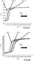
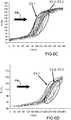
figures 6A à 6D sont des représentations graphiques des mesures de températures fournies par les thermocouples dans les différents niveaux des différents étages du réservoir de lafigure 5A .
- the
figure 1 is a longitudinal sectional view of an exemplary embodiment of a heat storage tank according to the invention, - the
figure 2 is a detail view of the reservoir of thefigure 1 schematically illustrated illustrating the operation of the reservoir, - the
Figures 3A and 3B are views from above of an exemplary embodiment of supports intended to delimit the compartments in the reservoir, - the
figure 3C is a sectional view according to the plan AA of thefigure 3A , - the
figure 4 is a top view of an exemplary embodiment of a dispenser that can be implemented in the tank according to the invention, - the
Figure 5A is a schematic longitudinal sectional view of a tank according to the invention on which are represented plans for measuring the temperature, - the
Figures 5B and 5C are cross-sectional views of the distribution of thermocouples in the coolant and in the different planes of the solid bed respectively, - the
Figures 6A to 6D are graphical representations of temperature measurements provided by the thermocouples in the different levels of the different stages of the reservoir of theFigure 5A .
Dans la description qui va suivre, les termes "étage" ou "compartiment" seront utilisés indistinctement.In the description that follows, the terms "floor" or "compartment" will be used indiscriminately.
Les termes "inférieur", "supérieur", "haut" et "bas" sont considérés par rapport à l'orientation du réservoir sur la
Sur la
Le réservoir comporte une enveloppe 2 cylindrique d'axe longitudinal X. Dans l'exemple représenté, le réservoir présente une section circulaire.The reservoir comprises a
L'axe longitudinal X est destiné à être orienté sensiblement verticalement comme dans la représentation de la
L'enveloppe 2 est formée d'une virole 4 et de deux fonds bombés 6, 8 fermant les extrémités longitudinales supérieure et inférieure respectivement de la virole 4.The
Le réservoir comporte des moyens d'admission et de collecte 10 de liquide chaud situés dans le fond bombé supérieur 6 du réservoir et des moyens d'admission et de collecte 12 du liquide froid situés dans le fond bombé inférieur 8 en partie basse du réservoir.The reservoir comprises hot liquid intake and collection means 10 located in the upper
L'intérieur du réservoir est divisé en plusieurs compartiments C1, C2, C3 se superposant le long de l'axe longitudinal X. Chaque compartiment C1, C2, C3 comporte un fond G1, G2, G3 formant support assurant la retenue d'éléments de stockage thermiques solides tout en permettant la communication fluidique entre les compartiments et un lit TH1, TH2, TH3 d'éléments solides de stockage thermique. Seul le lit TH1 est représenté par des éléments solides.The interior of the tank is divided into several compartments C1, C2, C3 superimposed along the longitudinal axis X. Each compartment C1, C2, C3 comprises a bottom G1, G2, G3 forming a support ensuring the retention of elements. solid thermal storage while allowing fluid communication between the compartments and a bed TH1, TH2, TH3 of solid thermal storage elements. Only the bed TH1 is represented by solid elements.
En outre, une couche de liquide caloporteur L1, L2, L3 recouvrent les lits TH1, TH2, TH3 d'éléments de stockage thermiques solides.In addition, a heat-transfer liquid layer L1, L2, L3 cover the beds TH1, TH2, TH3 of solid thermal storage elements.
Le volume utile du réservoir ne comporte pas de zone de vide, si bien que le volume non occupé par les éléments solides est rempli par le fluide caloporteur. La zone située au dessus du lit TH1 et délimitée par le fond bombé 6 n'est pas rempli de liquide et forme un ciel pour l'évacuation des vapeurs.The useful volume of the reservoir does not include a vacuum zone, so that the volume not occupied by the solid elements is filled by the heat transfer fluid. The zone situated above the bed TH1 and delimited by the
Dans l'exemple représenté, la zone située sous le lit TH3 délimité par le fond bombé inférieur 8 est rempli de liquide d'un matériau solide, par exemple de type béton. Ceci permet de plus de diminuer la quantité de fluide caloporteur mise en oeuvre.In the example shown, the zone under the TH3 bed delimited by the bottom
Les éléments de stockage thermique sont formés par exemple par des roches et/ou du sable. De préférence, les éléments présentent au moins deux granulométries assurant ainsi un bon remplissage et réduisant les espaces libres pour le liquide caloporteur. Avantageusement, les éléments de stockage thermique solides sont formés par des blocs de roches et du sable remplissant les espaces entre les roches.The thermal storage elements are formed for example by rocks and / or sand. Preferably, the elements have at least two granulometries thus ensuring a good filling and reducing the free spaces for the heat transfer liquid. Advantageously, the solid thermal storage elements are formed by blocks of rocks and sand filling the spaces between the rocks.
Chaque granulométrie correspond à un diamètre d50 d'éléments solides, défini comme la valeur pour laquelle 50 % des éléments solides ont un diamètre inférieur à d50. Le diamètre d50 est désigné également la médiane.Each particle size corresponds to a diameter d50 of solid elements, defined as the value for which 50% of the solid elements have a diameter less than d50. The diameter d50 is also referred to as the median.
De préférence, un facteur 10 entre les médianes des deux granulométries est choisi ce qui permet le remplissage de l'espace libre entre les grosses roches par les petites roches. Par exemple, les grosses roches ont un diamètre d'environ 3 cm et les petites roches ont un diamètre d'environ 3 mm. La répartition en volume est la suivante : environ 75% de grosses roches et 25% de petites roches en volume.Preferably, a factor of 10 between the medians of the two granulometries is chosen which allows the filling of the free space between the large rocks by the small rocks. For example, large rocks have a diameter of about 3 cm and small rocks have a diameter of about 3 mm. The volume distribution is as follows: about 75% large rocks and 25% small rocks by volume.
Il peut s'agir par exemple de roches alluvionnaires composées principalement de silice. Les roches sont choisies en fonction de leurs caractéristiques liées à la capacité de stockage thermique et à leur comportement thermique (masse volumique, capacité thermique massique et conductivité thermique) et à leur compatibilité avec le liquide caloporteur, par exemple la compatibilité entre la nature géologique de la roche et du liquide caloporteur.It may be, for example, alluvial rocks composed mainly of silica. The rocks are chosen according to their characteristics related to the thermal storage capacity and to their thermal behavior (density, specific heat capacity and thermal conductivity) and to their compatibility with the coolant, for example the compatibility between the geological nature of rock and coolant.
Le liquide caloporteur est par exemple de l'huile ou des sels fondus. Par exemple, l'huile peut être du Therminol66® ou Jarytherm DBT®, celle-ci ne montrant pas d'interactions particulières avec les roches alluvionnaires, de manière plus générale les huiles thermiques de synthèse haute température peuvent convenir en utilisation avec les roches alluvionnaires.The coolant is, for example, oil or molten salts. For example, the oil can be of Therminol66® or Jarytherm DBT®, the latter showing no specific interactions with alluvial rocks, more generally thermal oils high temperature synthesis may agree to use with alluvial rocks .
A des fins de simplicité les "lits d'éléments de stockage thermique solides" seront désignés par la suite "lit de stockage thermique".For the sake of simplicity the "beds of solid thermal storage elements" will be referred to hereafter as "thermal storage bed".
Les supports sont donc adaptés pour supporter mécaniquement les lits de stockage thermique, pour retenir les éléments de faible granulométrie, tels que le sable et à laisser passer le liquide caloporteur.The supports are therefore adapted to mechanically support the thermal storage beds, to retain the small particle size elements, such as sand and pass the heat transfer liquid.
Sur les
De manière avantageuse le support G1 est formé de deux demi-supports facilitant son montage dans la virole 4. Un support en une seule pièce ne sort pas du cadre de la présente invention.Advantageously the support G1 is formed of two half-supports facilitating its mounting in the
Sur les
La structure porteuse 14 est formée par des barres porteuses parallèles 20 solidarisées entre elles par des traverses 22 et réalisant une structure en forme de demi-cercle.The supporting
Sur la
La grille 18 est par exemple formée par une toile métallique dont la taille des mailles est telle qu'elle assure la retenue des éléments solides de plus faibles granulométries.The
Chaque support G1, G2, G3 est suspendu dans la virole par l'intermédiaire d'un taquet annulaire 23 bordant la surface intérieure de la virole à la hauteur souhaitée.Each support G1, G2, G3 is suspended in the ferrule by means of an
Les moyens d'admission et de collecte 10, 12 comportent de préférence un orifice pour collecter le fluide chaud et froid respectivement et des moyens de distribution pour alimenter le réservoir en fluide chaud et froid respectivement.The inlet and collection means 10, 12 preferably comprise an orifice for collecting the hot and cold fluid respectively and distribution means for supplying the reservoir with hot and cold fluid respectively.
Sur la
Les moyens de distribution 24 comportent un conduit d'alimentation 26 relié à l'alimentation en liquide extérieur et des conduits de distribution 28 connectés au conduit d'alimentation et s'étendant transversalement par rapport à celui-ci. Dans l'exemple représenté, les conduits de distribution 28 sont perpendiculaires au conduit d'alimentation 26. Chaque conduit est muni d'une pluralité d'orifices de distribution assurant une distribution du liquide le long de son axe.The distribution means 24 comprise a
Le conduit principal s'étend avantageusement le long d'un diamètre de la virole. De manière avantageuse également les conduits de distribution présentent des longueurs différentes en fonction de leur position le long du conduit principal de sorte que les moyens de distribution couvrent de manière sensiblement homogène toute la section transversale de la virole.The main duct advantageously extends along a diameter of the ferrule. Advantageously also the distribution ducts have different lengths depending on their position along the main duct so that the dispensing means substantially homogeneously cover the entire cross section of the ferrule.
D'autres formes de moyens de distribution peuvent être envisagées, de préférence ces formes assurant une répartition homogène des liquides alimentant le réservoir.Other forms of distribution means may be envisaged, preferably these forms ensuring a homogeneous distribution of liquids supplying the reservoir.
Sur la
On peut voir la couche de liquide L2 au dessus du lit de stockage thermique TH2 et au dessous du support G1 qui est recouvert du lit de stockage thermique TH1.The liquid layer L2 can be seen above the thermal storage bed TH2 and below the support G1 which is covered with the thermal storage bed TH1.
La flèche F symbolise les mouvements de convection naturelle qui apparaissent dans la couche de liquide L2 lorsqu'elle est le lieu d'inhomogénéités transversales de température.The arrow F symbolizes the natural convection movements that appear in the liquid layer L2 when it is the site of transverse inhomogeneities of temperature.
En cas d'inhomogénéités transversales de température, des gradients de température et donc des gradients de masse volumique de liquide apparaissent dans les couches liquides, ce qui conduit à l'apparition de mouvements de convection naturelle qui tendent à réduire ce gradient.In case of transverse inhomogeneities of temperature, temperature gradients and therefore liquid density gradients appear in the liquid layers, which leads to the appearance of natural convection movements that tend to reduce this gradient.
De préférence, l'épaisseur des couches de liquide est de l'ordre de 1 cm à 10 cm.Preferably, the thickness of the liquid layers is of the order of 1 cm to 10 cm.
Il a été constaté que pour des épaisseurs inférieures à 1 cm, la fonction de remélange global est moins bien assurée car les cellules de convection qui se créent ont un effet plus local.It has been found that for thicknesses less than 1 cm, the global remixing function is less well assured because the convection cells that are created have a more local effect.
Pour des épaisseurs supérieures à 10 cm, l'efficacité de la fonction de remélange est conservée. En revanche, plus l'épaisseur de la couche de liquide caloporteur est grande plus la quantité de liquide est importante. Or le coût du liquide est élevé. Il en résulte qu'un réservoir avec des couches liquides présentant une épaisseur importante est économiquement moins intéressant. De plus, des épaisseurs trop importantes de couches liquides se traduiraient par un remélange axial trop important qui réduirait l'efficacité du thermocline.For thicknesses greater than 10 cm, the effectiveness of the remixing function is retained. On the other hand, the greater the thickness of the heat-transfer liquid layer, the greater the quantity of liquid is important. But the cost of the liquid is high. As a result, a tank with liquid layers having a large thickness is economically less attractive. In addition, too large thicknesses of liquid layers would result in excessive axial remixing which would reduce the efficiency of the thermocline.
De manière avantageuse, les compartiments présentent tous sensiblement la même hauteur et la même composition en quantité de liquide et en quantité d'éléments solides de sorte à assurer un comportement homogène sur toute la hauteur du réservoir.Advantageously, the compartments all have substantially the same height and the same composition in amount of liquid and in amount of solid elements so as to ensure homogeneous behavior over the entire height of the tank.
La hauteur du réservoir de stockage est donc « découpée » en plusieurs régions de hauteur hi : h1, h2, h3 qui peuvent varier de quelques dizaines de centimètres à quelques mètres. La hauteur des lits est en pratique choisie de sorte à conserver un rapport hi/D<1, ce qui permet de réduite le phénomène mécanique de thermal ratcheting.The height of the storage tank is thus "cut" into several regions of height hi: h1, h2, h3 which can vary from a few tens of centimeters to a few meters. The height of the beds is in practice chosen so as to maintain a hi / D ratio <1, which reduces the mechanical phenomenon of thermal ratcheting.
A titre d'exemple uniquement, un réservoir présentant une température basse de 150°C et une température haute de 300°C, peut comporter une virole présentant un diamètre de 2500 mm, trois compartiments comprenant chacun un lit de stockage thermique de hauteur égale à 1900 mm et d'une couche de liquide caloporteur ayant une épaisseur de 100 mm.By way of example only, a tank having a low temperature of 150 ° C. and a high temperature of 300 ° C. may comprise a ferrule having a diameter of 2500 mm, three compartments each comprising a heat storage bed of height equal to 1900 mm and a heat transfer liquid layer having a thickness of 100 mm.
Nous allons maintenant montrer l'efficacité de la structure du réservoir selon l'invention.We will now show the efficiency of the tank structure according to the invention.
Pour cela, on considère un réservoir à quatre compartiments. Des mesures de température sont effectuées dans les couches de liquide L1 à L3 et à différentes hauteurs dans chaque lit de stockage thermique TH1, TH2, TH3, TH4 et en plusieurs points de plans transversaux de chaque lit correspondant aux différentes hauteurs. Les différentes hauteurs de mesure sont représentées sur la
Les mesures sont représentées sur les graphiques des
La charge est réalisée à la température de 170°C et le réservoir est initialement entièrement à la température de 60°C.The charge is carried out at a temperature of 170 ° C. and the tank is initially entirely at a temperature of 60 ° C.
L'avancée du front thermique est symbolisée par la flèche Fth sur les représentations graphiques.The advance of the thermal front is symbolized by the arrow Fth on the graphical representations.
L'analyse des mesures de température montrent que dans le compartiment supérieur C1, on distingue trois groupes de courbes correspondant au plan C1-3, au plan C1-2 et au plan C1-1. Au fur et à mesure que le front thermique progresse dans la virole le long de l'axe X, une inhomogénéité en température apparait : en effet on constate que les courbes sont de moins en moins groupées, ce qui traduit l'existence d'écarts de température entre des points de mesure situés sur un même plan. L'inhomogénéité de la température croît ainsi du plan C1-1 vers le plan C1-3.The analysis of the temperature measurements shows that in the upper compartment C1, there are three groups of curves corresponding to the plane C1-3, the plane C1-2 and the plane C1-1. As the thermal front progresses in the shell along the X axis, an inhomogeneity in temperature appears: in fact we see that the curves are less and less grouped, which reflects the existence of deviations temperature between measuring points located on the same plane. The inhomogeneity of the temperature thus increases from the C1-1 plane to the C1-3 plane.
Le passage du compartiment C1 au compartiment 2 se traduit par un resserrement des courbes dans le plan C2-1 par rapport à celles du plan C1-3 (
Le passage par la couche liquide L2 entre les lits TH1 et TH2 permet de réduire l'étalement du groupe de courbes, c'est-à-dire de réduire l'inhomogénéité en température.The passage through the liquid layer L2 between the TH1 and TH2 beds makes it possible to reduce the spreading of the group of curves, that is to say to reduce the inhomogeneity in temperature.
Le même phénomène apparaît à chacun des passages d'un compartiment à l'autre lors de la traversée d'une couche liquide.The same phenomenon appears at each passage from one compartment to another during the crossing of a liquid layer.
Dans les compartiments C3 et C4, on observe seulement deux groupes de courbes : un premier groupe bien resserré correspondant aux plans C3-1 et C4-1 et un groupe de courbes étalées correspondants aux deux nappes suivantes de mesure C3-2 et C3-3 et C4-2 et C4-3. Ceci illustre une inhomogénéité dans le réservoir due au lit de roches. Toutefois, le passage par la couche liquide L4 permet de rétablir l'homogénéité en température.In compartments C3 and C4, only two groups of curves are observed: a first well-tightened group corresponding to the C3-1 and C4-1 planes and a group of spread curves corresponding to the following two layers of measurement C3-2 and C3-3 and C4-2 and C4-3. This illustrates an inhomogeneity in the reservoir due to the bed of rocks. However, the passage through the liquid layer L4 makes it possible to restore the homogeneity in temperature.
Dans un réservoir selon l'invention, la réduction des inhomogénéités en température lors du passage par une couche uniquement liquide a été observée expérimentalement même en cas d'inhomogénéité forte de la température dans un plan situé en amont de la couche liquide. La couche de liquide permet également de retarder la déstabilisation du thermocline puisque la dispersion en température sur les plans C2-1, C3-1 et C4-1 est plus faible que sur le plan C1-3.In a tank according to the invention, the reduction in inhomogeneities in temperature during the passage through a solely liquid layer has been observed experimentally even in case of strong inhomogeneity of the temperature in a plane located upstream of the liquid layer. The liquid layer also makes it possible to delay the destabilization of the thermocline since the temperature dispersion on the C2-1, C3-1 and C4-1 planes is lower than on the C1-3 plane.
Le réservoir présente alors un fonctionnement amélioré qui se rapproche du fonctionnement en piston thermique. Le réservoir selon l'invention aide donc à maintenir une température constante en sortie du réservoir.The tank then has improved operation which is close to the operation of the thermal piston. The tank according to the invention thus helps to maintain a constant temperature at the outlet of the tank.
De plus la proportion utile du réservoir est augmentée. En effet, La réduction des inhomogénéités transversales en température permet d'obtenir un pourcentage de volume plus important du réservoir à température constante.In addition the useful proportion of the tank is increased. In fact, the reduction of transverse inhomogeneities in temperature makes it possible to obtain a larger percentage of volume of the tank at a constant temperature.
En outre, grâce à l'invention, il est possible de combiner les avantages d'un faible rapport hauteur du lit sur diamètre de la virole et d'un rapport hauteur total sur diamètre de la virole élevé.In addition, thanks to the invention, it is possible to combine the advantages of a low ratio bed height to ferrule diameter and a total height ratio to diameter of the ferrule high.
En effet, la segmentation du lit d'éléments solides permet d'atteindre, pour chaque compartiment, un rapport hauteur du lit de stockage thermique sur le diamètre de la virole inférieur à 1 ce qui permet de réduire l'effet de thermal ratcheting et donc d'assurer une bonne tenue mécanique. Et simultanément, la segmentation permet d'avoir une hauteur totale de lit d'élément solides importante et donc un rapport hauteur totale sur diamètre grand. On obtient donc des propriétés de stockage importantes en durée et en volume de zone isotherme.Indeed, the segmentation of the bed of solid elements makes it possible to achieve, for each compartment, a height ratio of the storage bed thermal on the diameter of the ferrule less than 1 which reduces the effect of thermal ratcheting and therefore ensure good mechanical strength. And simultaneously, the segmentation makes it possible to have a total height of the solid element bed important and thus a ratio of total height to large diameter. Important storage properties are thus obtained in terms of duration and volume of isothermal zone.
De plus, grâce à l'invention, il est possible de réduire l'épaisseur de la virole par rapport à celles de l'état de la technique puisque la poussée liée aux matériaux solide de stockage est répartie dans les différents compartiments. En outre, le phénomène de tassement lors des cycles thermiques est réparti dans les différents compartiments.In addition, thanks to the invention, it is possible to reduce the thickness of the shell compared to those of the state of the art since the thrust related to solid storage materials is distributed in the various compartments. In addition, the settling phenomenon during thermal cycles is distributed in the different compartments.
En outre, grâce à la répartition en compartiments, les moyens de distribution situés dans le fond inférieur du réservoir sont isolés des éléments solides de stockage thermique, ils ne sont alors plus soumis aux contraintes mécaniques liées par exemple au tassement de cette matrice lors des cycles thermiques.In addition, thanks to the division into compartments, the distribution means located in the lower bottom of the tank are isolated solids thermal storage, they are no longer subject to mechanical stresses related for example to the settlement of this matrix during cycles thermal.
Le réservoir selon l'invention peut être utilisé pour stocker la chaleur de toute installation ou système produisant de la chaleur.The tank according to the invention can be used to store the heat of any installation or system producing heat.
Il est particulièrement adapté à l'utilisation avec des systèmes utilisant des liquides présentant des températures maitrisées et constantes, tels que les turbines.It is particularly suitable for use with systems using liquids having controlled and constant temperatures, such as turbines.
Le réservoir selon la présente invention est particulièrement adapté à une utilisation dans une centrale solaire de type Fresnel pour alimenter une turbine. Il peut également être utilisé dans une centrale solaire à tour.The tank according to the present invention is particularly suitable for use in a Fresnel solar power plant for supplying a turbine. It can also be used in a solar tower plant.
Claims (15)
- Heat storage tank comprising an envelope (2) with a longitudinal axis (X) filled with a heat transfer liquid and solid heat storage elements, a first longitudinal end provided with first means (10) for collecting and supplying a liquid at a first temperature and a second longitudinal end provided with seconds means (12) for collecting and supplying a liquid at a second temperature, said tank beingcharacterised in that said solid heat storage elements are distributed across at least two beds (TH1, TH2, TH3) superposed along the longitudinal axis (X), separated by a layer of heat transfer liquid (L1, L2, L3), the heat transfer liquid being capable of flowing between the first longitudinal end and the second longitudinal end.
- Tank according to claim 1, in which each bed (TH1, TH2, TH3) rests on a support (G1, G2, G3) enabling fluid communication.
- Tank according to claim 2, in which at least one of the supports (G1, G2, G3) comprises a bearing structure (14) and a slatted structure (16) covered with a metal web plate (18).
- Tank according to claim 2 or 3, in which the supports (G1, G2, G3) are in two parts.
- Tank according to one of claims 1 to 4, in which the solid heat storage elements have at least two different particle sizes.
- Tank according to one of claims 1 to 5, in which the layer of heat transfer liquid (L1, L2, L3) has a thickness comprised between 1 cm and 10 cm.
- Tank according to one of claims 1 to 6, in which the envelope (2) is a shell and in which the height of each bed (G1, G2, G3) is less than the diameter of the envelope (2).
- Tank according to one of claims 1 to 7, in which the heat transfer liquid is an oil or/and in which the solid heat storage elements comprise blocks of rock and sand, the blocks of rock being advantageously formed from alluvial rocks.
- Tank according to one of claims 1 to 8, in which the first (10) and/or the second (12) collecting and supplying means comprise distribution means (24) assuring transversal homogeneity of the axial velocity of the fluid.
- Tank according to claim 9, in which the envelope (2) is a shell and the second distribution means (24) comprise a supply duct (26) extending along the diameter of the envelope (2) and distribution ducts (28) extending laterally from the supply duct, said distribution ducts (28) being provided with orifices distributed along the length thereof.
- Tank according to claim 10, in which the distribution ducts (28) have different lengths such that the contour of the distribution means (24) has substantially the shape of a circle.
- Tank according to one of claims 1 to 11, in which the second supplying and collecting means (12) are isolated from the solid heat storage elements.
- Solar power plant comprising at least one heat tank according to one of claims 1 to 12.
- Solar power plant according to claim 13, in which the solar power plant is a Fresnel type solar power plant or a tower solar power plant.
- Solar power plant according to claim 13 or 14, in which the first (10) and the second (12) means for collecting and supplying the tank are connected to a turbine.
Applications Claiming Priority (2)
| Application Number | Priority Date | Filing Date | Title |
|---|---|---|---|
| FR1254229AFR2990502B1 (en) | 2012-05-09 | 2012-05-09 | HEAT STORAGE TANK WITH IMPROVED THERMAL STRATIFICATION |
| PCT/EP2013/059400WO2013167538A1 (en) | 2012-05-09 | 2013-05-06 | Heat storage tank with improved thermal stratification |
Publications (2)
| Publication Number | Publication Date |
|---|---|
| EP2847535A1 EP2847535A1 (en) | 2015-03-18 |
| EP2847535B1true EP2847535B1 (en) | 2017-03-01 |
Family
ID=46826656
Family Applications (1)
| Application Number | Title | Priority Date | Filing Date |
|---|---|---|---|
| EP13724192.3AActiveEP2847535B1 (en) | 2012-05-09 | 2013-05-06 | Heat storage tank with improved thermal stratification |
Country Status (8)
| Country | Link |
|---|---|
| US (1) | US20150136115A1 (en) |
| EP (1) | EP2847535B1 (en) |
| AU (1) | AU2013258175B2 (en) |
| ES (1) | ES2627443T3 (en) |
| FR (1) | FR2990502B1 (en) |
| TN (1) | TN2014000473A1 (en) |
| WO (1) | WO2013167538A1 (en) |
| ZA (1) | ZA201408153B (en) |
Cited By (2)
| Publication number | Priority date | Publication date | Assignee | Title |
|---|---|---|---|---|
| EP2738509B1 (en)* | 2012-11-28 | 2018-10-17 | Electricité de France | Container for thermal storage material, with a reinforced structure |
| EP4012319A1 (en)* | 2020-12-14 | 2022-06-15 | Commissariat à l'énergie atomique et aux énergies alternatives | Regenerative storage device |
Families Citing this family (27)
| Publication number | Priority date | Publication date | Assignee | Title |
|---|---|---|---|---|
| US10094219B2 (en) | 2010-03-04 | 2018-10-09 | X Development Llc | Adiabatic salt energy storage |
| WO2014052927A1 (en) | 2012-09-27 | 2014-04-03 | Gigawatt Day Storage Systems, Inc. | Systems and methods for energy storage and retrieval |
| DK2902740T3 (en)* | 2014-01-31 | 2019-02-25 | Siemens Ag | Thermal energy storage with reduced internal natural convection |
| FR3037642B1 (en)* | 2015-06-16 | 2017-06-23 | Commissariat Energie Atomique | THERMAL STORAGE TANK. |
| FR3048075B1 (en) | 2016-02-19 | 2018-03-23 | IFP Energies Nouvelles | SYSTEM AND METHOD FOR HEAT STORAGE AND RESTITUTION COMPRISING A BED OF PARTICLES AND MEANS FOR THERMAL REGULATION |
| FR3048493B1 (en)* | 2016-03-04 | 2019-06-14 | Commissariat A L'energie Atomique Et Aux Energies Alternatives | HEAT STORAGE TANK WITH OPTIMIZED OPERATION |
| US10233787B2 (en) | 2016-12-28 | 2019-03-19 | Malta Inc. | Storage of excess heat in cold side of heat engine |
| US10233833B2 (en) | 2016-12-28 | 2019-03-19 | Malta Inc. | Pump control of closed cycle power generation system |
| US11053847B2 (en)* | 2016-12-28 | 2021-07-06 | Malta Inc. | Baffled thermoclines in thermodynamic cycle systems |
| US10458284B2 (en) | 2016-12-28 | 2019-10-29 | Malta Inc. | Variable pressure inventory control of closed cycle system with a high pressure tank and an intermediate pressure tank |
| US10221775B2 (en) | 2016-12-29 | 2019-03-05 | Malta Inc. | Use of external air for closed cycle inventory control |
| US10801404B2 (en) | 2016-12-30 | 2020-10-13 | Malta Inc. | Variable pressure turbine |
| US10436109B2 (en) | 2016-12-31 | 2019-10-08 | Malta Inc. | Modular thermal storage |
| FR3068120B1 (en)* | 2017-06-21 | 2019-10-18 | Arkema France | HEAT STORAGE TANK OPTIMIZED FROM CALCIUM CARBONATE PARTICLES |
| EP4451551A3 (en) | 2018-01-11 | 2025-01-22 | Lancium Llc | Method and system for dynamic power delivery to a flexible datacenter using unutilized energy sources |
| CN109945731B (en)* | 2019-04-12 | 2024-05-24 | 浙江宝威电气有限公司 | Heat storage body supporting structure for solar heat storage tank |
| EP3764048A1 (en)* | 2019-07-09 | 2021-01-13 | Siemens Gamesa Renewable Energy GmbH & Co. KG | Thermal energy storage |
| CN116575992A (en) | 2019-11-16 | 2023-08-11 | 马耳他股份有限公司 | Dual power system pumping thermoelectric storage state conversion |
| US11454167B1 (en) | 2020-08-12 | 2022-09-27 | Malta Inc. | Pumped heat energy storage system with hot-side thermal integration |
| CA3189001A1 (en) | 2020-08-12 | 2022-02-17 | Mert Geveci | Pumped heat energy storage system with modular turbomachinery |
| US11486305B2 (en) | 2020-08-12 | 2022-11-01 | Malta Inc. | Pumped heat energy storage system with load following |
| EP4193036A1 (en) | 2020-08-12 | 2023-06-14 | Malta Inc. | Pumped heat energy storage system with steam cycle |
| US11396826B2 (en) | 2020-08-12 | 2022-07-26 | Malta Inc. | Pumped heat energy storage system with electric heating integration |
| US11286804B2 (en) | 2020-08-12 | 2022-03-29 | Malta Inc. | Pumped heat energy storage system with charge cycle thermal integration |
| US11480067B2 (en) | 2020-08-12 | 2022-10-25 | Malta Inc. | Pumped heat energy storage system with generation cycle thermal integration |
| CN113405078B (en)* | 2021-07-09 | 2024-12-10 | 上海电气集团股份有限公司 | A heat storage steam supply system |
| EP4430285A1 (en) | 2021-12-14 | 2024-09-18 | Malta Inc. | Pumped heat energy storage system integrated with coal-fired energy generation unit |
Family Cites Families (21)
| Publication number | Priority date | Publication date | Assignee | Title |
|---|---|---|---|---|
| US655274A (en)* | 1899-11-23 | 1900-08-07 | Robert Ramsden | Steam-generator. |
| US2492788A (en)* | 1947-05-24 | 1949-12-27 | Air Reduction | Regenerator |
| US4124061A (en)* | 1976-11-01 | 1978-11-07 | Rockwell International Corporation | Thermal energy storage unit |
| US4405010A (en)* | 1978-06-28 | 1983-09-20 | Sanders Associates, Inc. | Sensible heat storage unit |
| US4423558A (en)* | 1978-09-21 | 1984-01-03 | St. Gobain Vitrage | Device for heat exchange between solid particles and a gas current |
| US4291670A (en)* | 1980-07-08 | 1981-09-29 | Hyatt Everett C | Gas fired fireplace insert with heat extractor |
| US4418683A (en)* | 1981-04-23 | 1983-12-06 | Rockwell International Corporation | Separated phase thermal storage system |
| US4448239A (en)* | 1982-04-16 | 1984-05-15 | The United States Of America As Represented By The Secretary Of The Army | Heat-pipe-diode-charged thermal |
| US4524756A (en)* | 1983-07-25 | 1985-06-25 | Chicago Bridge & Iron Company | Thermal energy storage tank using modular heat batteries |
| JP2746943B2 (en)* | 1988-10-03 | 1998-05-06 | 工業技術院長 | Regenerator |
| US5596981A (en)* | 1993-07-19 | 1997-01-28 | Soucy; Paul B. | Solar device and method for assembly |
| US5941238A (en)* | 1997-02-25 | 1999-08-24 | Ada Tracy | Heat storage vessels for use with heat pumps and solar panels |
| US20080066736A1 (en)* | 2006-07-25 | 2008-03-20 | Yanong Zhu | Method and apparatus for solar energy storage system using gas and rock |
| CN101769643B (en)* | 2009-01-06 | 2011-08-10 | 成都钟顺科技发展有限公司 | Follow-up large-scale Fresnel lens point focusing solar system |
| US20110094706A1 (en)* | 2009-10-26 | 2011-04-28 | Dritan Ramani | Thermal stratified tank |
| US20110108020A1 (en)* | 2009-11-11 | 2011-05-12 | Mcenerney Bryan William | Ballast member for reducing active volume of a vessel |
| FR2955039B1 (en)* | 2010-01-11 | 2012-10-19 | Commissariat Energie Atomique | CHEMICAL REACTOR DEVICE WITH IMPROVED EFFICIENCY INTEGRATING A THERMAL EXCHANGE CIRCUIT |
| US10168105B2 (en)* | 2010-05-04 | 2019-01-01 | Basf Se | Device and method for storing heat |
| US8863516B2 (en)* | 2011-08-23 | 2014-10-21 | Chevron U.S.A. Inc. | System for collecting concentrated solar radiation |
| FR2990501A1 (en)* | 2012-05-09 | 2013-11-15 | Commissariat Energie Atomique | METHOD FOR FILLING A HEAT STORAGE TANK INTO SOLID ELEMENTS |
| WO2013167158A1 (en)* | 2012-05-11 | 2013-11-14 | Vladan Petrovic | Long-term heat storage device and method for long-term heat storage of solar energy and other types of energy with changing availability |
- 2012
- 2012-05-09FRFR1254229Apatent/FR2990502B1/enactiveActive
- 2013
- 2013-05-06AUAU2013258175Apatent/AU2013258175B2/enactiveActive
- 2013-05-06USUS14/399,653patent/US20150136115A1/ennot_activeAbandoned
- 2013-05-06ESES13724192.3Tpatent/ES2627443T3/enactiveActive
- 2013-05-06WOPCT/EP2013/059400patent/WO2013167538A1/enactiveApplication Filing
- 2013-05-06EPEP13724192.3Apatent/EP2847535B1/enactiveActive
- 2014
- 2014-11-07TNTN2014000473Apatent/TN2014000473A1/enunknown
- 2014-11-07ZAZA2014/08153Apatent/ZA201408153B/enunknown
Non-Patent Citations (1)
| Title |
|---|
| None* |
Cited By (3)
| Publication number | Priority date | Publication date | Assignee | Title |
|---|---|---|---|---|
| EP2738509B1 (en)* | 2012-11-28 | 2018-10-17 | Electricité de France | Container for thermal storage material, with a reinforced structure |
| EP4012319A1 (en)* | 2020-12-14 | 2022-06-15 | Commissariat à l'énergie atomique et aux énergies alternatives | Regenerative storage device |
| FR3117580A1 (en)* | 2020-12-14 | 2022-06-17 | Commissariat A L'energie Atomique Et Aux Energies Alternatives | REGENERATIVE STORAGE DEVICE |
Also Published As
| Publication number | Publication date |
|---|---|
| FR2990502B1 (en) | 2014-06-06 |
| AU2013258175B2 (en) | 2018-01-25 |
| US20150136115A1 (en) | 2015-05-21 |
| TN2014000473A1 (en) | 2016-03-30 |
| ZA201408153B (en) | 2015-11-25 |
| WO2013167538A1 (en) | 2013-11-14 |
| ES2627443T3 (en) | 2017-07-28 |
| FR2990502A1 (en) | 2013-11-15 |
| EP2847535A1 (en) | 2015-03-18 |
| AU2013258175A1 (en) | 2014-11-27 |
Similar Documents
| Publication | Publication Date | Title |
|---|---|---|
| EP2847535B1 (en) | Heat storage tank with improved thermal stratification | |
| EP2867603B1 (en) | Method for filling a heat storage tank with solid elements | |
| EP3176529B1 (en) | System and method for storing and restoring energy by compressed gas | |
| EP3201554B1 (en) | Thermal storage unit | |
| WO2011154534A1 (en) | Absorber for a solar receiver and solar receiver comprising at least one such absorber | |
| FR3044751A1 (en) | SYSTEM AND METHOD FOR STORING AND RECOVERING COMPRESSED GAS ENERGY WITH RADIAL HEAT EXCHANGE | |
| FR2524124A1 (en) | CALORIFIC STORAGE AND RETURN PROCESS, AND DEVICE FOR IMPLEMENTING IT, CONSTITUTING A BUILDING ELEMENT | |
| EP3994409B1 (en) | Horizontal-axis heat recovery and storage system | |
| FR3038376B1 (en) | PHASE CHANGE MATERIAL ENERGY STORAGE DEVICE AND STORAGE METHOD THEREOF | |
| FR3098287A1 (en) | A system and method for storing and recovering heat, comprising a radial passage through storage particles. | |
| FR3082924A1 (en) | PHASE CHANGE MATERIAL (MCP) THERMAL STORAGE SYSTEM (SST) COMPRISING A GAS INJECTION CRYSTALLIZATION CONTROL DEVICE | |
| EP3423772B1 (en) | Heat storage tank with optimized operation | |
| EP3214398B1 (en) | Energy storage device by phase change material including an electrical load integrated in the fluid circuit | |
| WO2021023834A1 (en) | Improved heat storage device | |
| EP3435018B1 (en) | Device for storing thermal energy having an internal tank and a coolant distribution system | |
| EP3311091B1 (en) | Heat storage tank | |
| FR3050263A1 (en) | THERMAL ENERGY STORAGE DEVICE THROUGH PHASE CHANGE MATERIAL COMPRISING AN ELEMENT FOR CREATING LOAD LOSS | |
| EP3392595B1 (en) | Coolant distribution system for a thermal energy storage device including thermostatic systems | |
| EP4012319A1 (en) | Regenerative storage device | |
| FR3160457A1 (en) | Thermal storage enclosure for hot and cold by coupling between thermocline storage and MCP storage | |
| EP2655977A1 (en) | System for producing domestic hot water using solar collectors for water heating, in which a single circuit connects a hot water tank and the solar collectors |
Legal Events
| Date | Code | Title | Description |
|---|---|---|---|
| PUAI | Public reference made under article 153(3) epc to a published international application that has entered the european phase | Free format text:ORIGINAL CODE: 0009012 | |
| 17P | Request for examination filed | Effective date:20141118 | |
| AK | Designated contracting states | Kind code of ref document:A1 Designated state(s):AL AT BE BG CH CY CZ DE DK EE ES FI FR GB GR HR HU IE IS IT LI LT LU LV MC MK MT NL NO PL PT RO RS SE SI SK SM TR | |
| AX | Request for extension of the european patent | Extension state:BA ME | |
| DAX | Request for extension of the european patent (deleted) | ||
| GRAP | Despatch of communication of intention to grant a patent | Free format text:ORIGINAL CODE: EPIDOSNIGR1 | |
| INTG | Intention to grant announced | Effective date:20160908 | |
| GRAJ | Information related to disapproval of communication of intention to grant by the applicant or resumption of examination proceedings by the epo deleted | Free format text:ORIGINAL CODE: EPIDOSDIGR1 | |
| STAA | Information on the status of an ep patent application or granted ep patent | Free format text:STATUS: REQUEST FOR EXAMINATION WAS MADE | |
| GRAR | Information related to intention to grant a patent recorded | Free format text:ORIGINAL CODE: EPIDOSNIGR71 | |
| GRAS | Grant fee paid | Free format text:ORIGINAL CODE: EPIDOSNIGR3 | |
| STAA | Information on the status of an ep patent application or granted ep patent | Free format text:STATUS: GRANT OF PATENT IS INTENDED | |
| GRAA | (expected) grant | Free format text:ORIGINAL CODE: 0009210 | |
| STAA | Information on the status of an ep patent application or granted ep patent | Free format text:STATUS: THE PATENT HAS BEEN GRANTED | |
| INTC | Intention to grant announced (deleted) | ||
| AK | Designated contracting states | Kind code of ref document:B1 Designated state(s):AL AT BE BG CH CY CZ DE DK EE ES FI FR GB GR HR HU IE IS IT LI LT LU LV MC MK MT NL NO PL PT RO RS SE SI SK SM TR | |
| INTG | Intention to grant announced | Effective date:20170125 | |
| REG | Reference to a national code | Ref country code:GB Ref legal event code:FG4D Free format text:NOT ENGLISH | |
| REG | Reference to a national code | Ref country code:CH Ref legal event code:EP Ref country code:AT Ref legal event code:REF Ref document number:871875 Country of ref document:AT Kind code of ref document:T Effective date:20170315 | |
| REG | Reference to a national code | Ref country code:IE Ref legal event code:FG4D Free format text:LANGUAGE OF EP DOCUMENT: FRENCH | |
| REG | Reference to a national code | Ref country code:DE Ref legal event code:R096 Ref document number:602013017974 Country of ref document:DE | |
| REG | Reference to a national code | Ref country code:FR Ref legal event code:PLFP Year of fee payment:5 | |
| REG | Reference to a national code | Ref country code:NL Ref legal event code:MP Effective date:20170301 | |
| REG | Reference to a national code | Ref country code:LT Ref legal event code:MG4D | |
| REG | Reference to a national code | Ref country code:AT Ref legal event code:MK05 Ref document number:871875 Country of ref document:AT Kind code of ref document:T Effective date:20170301 | |
| REG | Reference to a national code | Ref country code:ES Ref legal event code:FG2A Ref document number:2627443 Country of ref document:ES Kind code of ref document:T3 Effective date:20170728 | |
| PG25 | Lapsed in a contracting state [announced via postgrant information from national office to epo] | Ref country code:NO Free format text:LAPSE BECAUSE OF FAILURE TO SUBMIT A TRANSLATION OF THE DESCRIPTION OR TO PAY THE FEE WITHIN THE PRESCRIBED TIME-LIMIT Effective date:20170601 Ref country code:LT Free format text:LAPSE BECAUSE OF FAILURE TO SUBMIT A TRANSLATION OF THE DESCRIPTION OR TO PAY THE FEE WITHIN THE PRESCRIBED TIME-LIMIT Effective date:20170301 Ref country code:HR Free format text:LAPSE BECAUSE OF FAILURE TO SUBMIT A TRANSLATION OF THE DESCRIPTION OR TO PAY THE FEE WITHIN THE PRESCRIBED TIME-LIMIT Effective date:20170301 Ref country code:FI Free format text:LAPSE BECAUSE OF FAILURE TO SUBMIT A TRANSLATION OF THE DESCRIPTION OR TO PAY THE FEE WITHIN THE PRESCRIBED TIME-LIMIT Effective date:20170301 | |
| PG25 | Lapsed in a contracting state [announced via postgrant information from national office to epo] | Ref country code:RS Free format text:LAPSE BECAUSE OF FAILURE TO SUBMIT A TRANSLATION OF THE DESCRIPTION OR TO PAY THE FEE WITHIN THE PRESCRIBED TIME-LIMIT Effective date:20170301 Ref country code:BG Free format text:LAPSE BECAUSE OF FAILURE TO SUBMIT A TRANSLATION OF THE DESCRIPTION OR TO PAY THE FEE WITHIN THE PRESCRIBED TIME-LIMIT Effective date:20170601 Ref country code:SE Free format text:LAPSE BECAUSE OF FAILURE TO SUBMIT A TRANSLATION OF THE DESCRIPTION OR TO PAY THE FEE WITHIN THE PRESCRIBED TIME-LIMIT Effective date:20170301 Ref country code:LV Free format text:LAPSE BECAUSE OF FAILURE TO SUBMIT A TRANSLATION OF THE DESCRIPTION OR TO PAY THE FEE WITHIN THE PRESCRIBED TIME-LIMIT Effective date:20170301 Ref country code:AT Free format text:LAPSE BECAUSE OF FAILURE TO SUBMIT A TRANSLATION OF THE DESCRIPTION OR TO PAY THE FEE WITHIN THE PRESCRIBED TIME-LIMIT Effective date:20170301 Ref country code:LU Free format text:LAPSE BECAUSE OF NON-PAYMENT OF DUE FEES Effective date:20170531 | |
| PG25 | Lapsed in a contracting state [announced via postgrant information from national office to epo] | Ref country code:NL Free format text:LAPSE BECAUSE OF FAILURE TO SUBMIT A TRANSLATION OF THE DESCRIPTION OR TO PAY THE FEE WITHIN THE PRESCRIBED TIME-LIMIT Effective date:20170301 | |
| PG25 | Lapsed in a contracting state [announced via postgrant information from national office to epo] | Ref country code:RO Free format text:LAPSE BECAUSE OF FAILURE TO SUBMIT A TRANSLATION OF THE DESCRIPTION OR TO PAY THE FEE WITHIN THE PRESCRIBED TIME-LIMIT Effective date:20170301 Ref country code:SK Free format text:LAPSE BECAUSE OF FAILURE TO SUBMIT A TRANSLATION OF THE DESCRIPTION OR TO PAY THE FEE WITHIN THE PRESCRIBED TIME-LIMIT Effective date:20170301 Ref country code:EE Free format text:LAPSE BECAUSE OF FAILURE TO SUBMIT A TRANSLATION OF THE DESCRIPTION OR TO PAY THE FEE WITHIN THE PRESCRIBED TIME-LIMIT Effective date:20170301 Ref country code:CZ Free format text:LAPSE BECAUSE OF FAILURE TO SUBMIT A TRANSLATION OF THE DESCRIPTION OR TO PAY THE FEE WITHIN THE PRESCRIBED TIME-LIMIT Effective date:20170301 | |
| REG | Reference to a national code | Ref country code:GR Ref legal event code:EP Ref document number:20170401475 Country of ref document:GR Effective date:20171023 | |
| PG25 | Lapsed in a contracting state [announced via postgrant information from national office to epo] | Ref country code:IS Free format text:LAPSE BECAUSE OF FAILURE TO SUBMIT A TRANSLATION OF THE DESCRIPTION OR TO PAY THE FEE WITHIN THE PRESCRIBED TIME-LIMIT Effective date:20170701 Ref country code:PL Free format text:LAPSE BECAUSE OF FAILURE TO SUBMIT A TRANSLATION OF THE DESCRIPTION OR TO PAY THE FEE WITHIN THE PRESCRIBED TIME-LIMIT Effective date:20170301 Ref country code:SM Free format text:LAPSE BECAUSE OF FAILURE TO SUBMIT A TRANSLATION OF THE DESCRIPTION OR TO PAY THE FEE WITHIN THE PRESCRIBED TIME-LIMIT Effective date:20170301 Ref country code:PT Free format text:LAPSE BECAUSE OF FAILURE TO SUBMIT A TRANSLATION OF THE DESCRIPTION OR TO PAY THE FEE WITHIN THE PRESCRIBED TIME-LIMIT Effective date:20170703 | |
| REG | Reference to a national code | Ref country code:DE Ref legal event code:R097 Ref document number:602013017974 Country of ref document:DE | |
| REG | Reference to a national code | Ref country code:CH Ref legal event code:PL | |
| PLBE | No opposition filed within time limit | Free format text:ORIGINAL CODE: 0009261 | |
| STAA | Information on the status of an ep patent application or granted ep patent | Free format text:STATUS: NO OPPOSITION FILED WITHIN TIME LIMIT | |
| PG25 | Lapsed in a contracting state [announced via postgrant information from national office to epo] | Ref country code:DK Free format text:LAPSE BECAUSE OF FAILURE TO SUBMIT A TRANSLATION OF THE DESCRIPTION OR TO PAY THE FEE WITHIN THE PRESCRIBED TIME-LIMIT Effective date:20170301 Ref country code:MC Free format text:LAPSE BECAUSE OF FAILURE TO SUBMIT A TRANSLATION OF THE DESCRIPTION OR TO PAY THE FEE WITHIN THE PRESCRIBED TIME-LIMIT Effective date:20170301 | |
| 26N | No opposition filed | Effective date:20171204 | |
| REG | Reference to a national code | Ref country code:IE Ref legal event code:MM4A | |
| GBPC | Gb: european patent ceased through non-payment of renewal fee | Effective date:20170601 | |
| PG25 | Lapsed in a contracting state [announced via postgrant information from national office to epo] | Ref country code:CH Free format text:LAPSE BECAUSE OF NON-PAYMENT OF DUE FEES Effective date:20170531 Ref country code:SI Free format text:LAPSE BECAUSE OF FAILURE TO SUBMIT A TRANSLATION OF THE DESCRIPTION OR TO PAY THE FEE WITHIN THE PRESCRIBED TIME-LIMIT Effective date:20170301 Ref country code:LI Free format text:LAPSE BECAUSE OF NON-PAYMENT OF DUE FEES Effective date:20170531 | |
| PG25 | Lapsed in a contracting state [announced via postgrant information from national office to epo] | Ref country code:LU Free format text:LAPSE BECAUSE OF NON-PAYMENT OF DUE FEES Effective date:20170506 | |
| REG | Reference to a national code | Ref country code:BE Ref legal event code:MM Effective date:20170531 | |
| PG25 | Lapsed in a contracting state [announced via postgrant information from national office to epo] | Ref country code:GB Free format text:LAPSE BECAUSE OF NON-PAYMENT OF DUE FEES Effective date:20170601 Ref country code:IE Free format text:LAPSE BECAUSE OF NON-PAYMENT OF DUE FEES Effective date:20170506 | |
| REG | Reference to a national code | Ref country code:FR Ref legal event code:PLFP Year of fee payment:6 | |
| PG25 | Lapsed in a contracting state [announced via postgrant information from national office to epo] | Ref country code:BE Free format text:LAPSE BECAUSE OF NON-PAYMENT OF DUE FEES Effective date:20170531 | |
| PG25 | Lapsed in a contracting state [announced via postgrant information from national office to epo] | Ref country code:MT Free format text:LAPSE BECAUSE OF FAILURE TO SUBMIT A TRANSLATION OF THE DESCRIPTION OR TO PAY THE FEE WITHIN THE PRESCRIBED TIME-LIMIT Effective date:20170301 | |
| PG25 | Lapsed in a contracting state [announced via postgrant information from national office to epo] | Ref country code:HU Free format text:LAPSE BECAUSE OF FAILURE TO SUBMIT A TRANSLATION OF THE DESCRIPTION OR TO PAY THE FEE WITHIN THE PRESCRIBED TIME-LIMIT; INVALID AB INITIO Effective date:20130506 | |
| PG25 | Lapsed in a contracting state [announced via postgrant information from national office to epo] | Ref country code:CY Free format text:LAPSE BECAUSE OF FAILURE TO SUBMIT A TRANSLATION OF THE DESCRIPTION OR TO PAY THE FEE WITHIN THE PRESCRIBED TIME-LIMIT Effective date:20170301 | |
| PG25 | Lapsed in a contracting state [announced via postgrant information from national office to epo] | Ref country code:MK Free format text:LAPSE BECAUSE OF FAILURE TO SUBMIT A TRANSLATION OF THE DESCRIPTION OR TO PAY THE FEE WITHIN THE PRESCRIBED TIME-LIMIT Effective date:20170301 | |
| PG25 | Lapsed in a contracting state [announced via postgrant information from national office to epo] | Ref country code:AL Free format text:LAPSE BECAUSE OF FAILURE TO SUBMIT A TRANSLATION OF THE DESCRIPTION OR TO PAY THE FEE WITHIN THE PRESCRIBED TIME-LIMIT Effective date:20170301 | |
| PGFP | Annual fee paid to national office [announced via postgrant information from national office to epo] | Ref country code:GR Payment date:20240517 Year of fee payment:12 | |
| PGFP | Annual fee paid to national office [announced via postgrant information from national office to epo] | Ref country code:TR Payment date:20240502 Year of fee payment:12 | |
| PGFP | Annual fee paid to national office [announced via postgrant information from national office to epo] | Ref country code:DE Payment date:20250519 Year of fee payment:13 | |
| PGFP | Annual fee paid to national office [announced via postgrant information from national office to epo] | Ref country code:ES Payment date:20250616 Year of fee payment:13 | |
| PGFP | Annual fee paid to national office [announced via postgrant information from national office to epo] | Ref country code:IT Payment date:20250530 Year of fee payment:13 | |
| PGFP | Annual fee paid to national office [announced via postgrant information from national office to epo] | Ref country code:FR Payment date:20250526 Year of fee payment:13 |