EP2846743B1 - Vascular prosthetic delivery device - Google Patents
Vascular prosthetic delivery deviceDownload PDFInfo
- Publication number
- EP2846743B1 EP2846743B1EP13714110.7AEP13714110AEP2846743B1EP 2846743 B1EP2846743 B1EP 2846743B1EP 13714110 AEP13714110 AEP 13714110AEP 2846743 B1EP2846743 B1EP 2846743B1
- Authority
- EP
- European Patent Office
- Prior art keywords
- proximal
- handle
- handle body
- catheter
- push rod
- Prior art date
- Legal status (The legal status is an assumption and is not a legal conclusion. Google has not performed a legal analysis and makes no representation as to the accuracy of the status listed.)
- Active
Links
Images


Classifications
- A—HUMAN NECESSITIES
- A61—MEDICAL OR VETERINARY SCIENCE; HYGIENE
- A61F—FILTERS IMPLANTABLE INTO BLOOD VESSELS; PROSTHESES; DEVICES PROVIDING PATENCY TO, OR PREVENTING COLLAPSING OF, TUBULAR STRUCTURES OF THE BODY, e.g. STENTS; ORTHOPAEDIC, NURSING OR CONTRACEPTIVE DEVICES; FOMENTATION; TREATMENT OR PROTECTION OF EYES OR EARS; BANDAGES, DRESSINGS OR ABSORBENT PADS; FIRST-AID KITS
- A61F2/00—Filters implantable into blood vessels; Prostheses, i.e. artificial substitutes or replacements for parts of the body; Appliances for connecting them with the body; Devices providing patency to, or preventing collapsing of, tubular structures of the body, e.g. stents
- A61F2/95—Instruments specially adapted for placement or removal of stents or stent-grafts
- A61F2/962—Instruments specially adapted for placement or removal of stents or stent-grafts having an outer sleeve
- A61F2/966—Instruments specially adapted for placement or removal of stents or stent-grafts having an outer sleeve with relative longitudinal movement between outer sleeve and prosthesis, e.g. using a push rod
- A—HUMAN NECESSITIES
- A61—MEDICAL OR VETERINARY SCIENCE; HYGIENE
- A61F—FILTERS IMPLANTABLE INTO BLOOD VESSELS; PROSTHESES; DEVICES PROVIDING PATENCY TO, OR PREVENTING COLLAPSING OF, TUBULAR STRUCTURES OF THE BODY, e.g. STENTS; ORTHOPAEDIC, NURSING OR CONTRACEPTIVE DEVICES; FOMENTATION; TREATMENT OR PROTECTION OF EYES OR EARS; BANDAGES, DRESSINGS OR ABSORBENT PADS; FIRST-AID KITS
- A61F2/00—Filters implantable into blood vessels; Prostheses, i.e. artificial substitutes or replacements for parts of the body; Appliances for connecting them with the body; Devices providing patency to, or preventing collapsing of, tubular structures of the body, e.g. stents
- A61F2/95—Instruments specially adapted for placement or removal of stents or stent-grafts
- A—HUMAN NECESSITIES
- A61—MEDICAL OR VETERINARY SCIENCE; HYGIENE
- A61F—FILTERS IMPLANTABLE INTO BLOOD VESSELS; PROSTHESES; DEVICES PROVIDING PATENCY TO, OR PREVENTING COLLAPSING OF, TUBULAR STRUCTURES OF THE BODY, e.g. STENTS; ORTHOPAEDIC, NURSING OR CONTRACEPTIVE DEVICES; FOMENTATION; TREATMENT OR PROTECTION OF EYES OR EARS; BANDAGES, DRESSINGS OR ABSORBENT PADS; FIRST-AID KITS
- A61F2/00—Filters implantable into blood vessels; Prostheses, i.e. artificial substitutes or replacements for parts of the body; Appliances for connecting them with the body; Devices providing patency to, or preventing collapsing of, tubular structures of the body, e.g. stents
- A61F2/82—Devices providing patency to, or preventing collapsing of, tubular structures of the body, e.g. stents
- A61F2/86—Stents in a form characterised by the wire-like elements; Stents in the form characterised by a net-like or mesh-like structure
- A61F2/90—Stents in a form characterised by the wire-like elements; Stents in the form characterised by a net-like or mesh-like structure characterised by a net-like or mesh-like structure
- A61F2/91—Stents in a form characterised by the wire-like elements; Stents in the form characterised by a net-like or mesh-like structure characterised by a net-like or mesh-like structure made from perforated sheets or tubes, e.g. perforated by laser cuts or etched holes
- A—HUMAN NECESSITIES
- A61—MEDICAL OR VETERINARY SCIENCE; HYGIENE
- A61F—FILTERS IMPLANTABLE INTO BLOOD VESSELS; PROSTHESES; DEVICES PROVIDING PATENCY TO, OR PREVENTING COLLAPSING OF, TUBULAR STRUCTURES OF THE BODY, e.g. STENTS; ORTHOPAEDIC, NURSING OR CONTRACEPTIVE DEVICES; FOMENTATION; TREATMENT OR PROTECTION OF EYES OR EARS; BANDAGES, DRESSINGS OR ABSORBENT PADS; FIRST-AID KITS
- A61F2/00—Filters implantable into blood vessels; Prostheses, i.e. artificial substitutes or replacements for parts of the body; Appliances for connecting them with the body; Devices providing patency to, or preventing collapsing of, tubular structures of the body, e.g. stents
- A61F2/95—Instruments specially adapted for placement or removal of stents or stent-grafts
- A61F2/9517—Instruments specially adapted for placement or removal of stents or stent-grafts handle assemblies therefor
- A—HUMAN NECESSITIES
- A61—MEDICAL OR VETERINARY SCIENCE; HYGIENE
- A61F—FILTERS IMPLANTABLE INTO BLOOD VESSELS; PROSTHESES; DEVICES PROVIDING PATENCY TO, OR PREVENTING COLLAPSING OF, TUBULAR STRUCTURES OF THE BODY, e.g. STENTS; ORTHOPAEDIC, NURSING OR CONTRACEPTIVE DEVICES; FOMENTATION; TREATMENT OR PROTECTION OF EYES OR EARS; BANDAGES, DRESSINGS OR ABSORBENT PADS; FIRST-AID KITS
- A61F2/00—Filters implantable into blood vessels; Prostheses, i.e. artificial substitutes or replacements for parts of the body; Appliances for connecting them with the body; Devices providing patency to, or preventing collapsing of, tubular structures of the body, e.g. stents
- A61F2/95—Instruments specially adapted for placement or removal of stents or stent-grafts
- A61F2/962—Instruments specially adapted for placement or removal of stents or stent-grafts having an outer sleeve
- A61F2/966—Instruments specially adapted for placement or removal of stents or stent-grafts having an outer sleeve with relative longitudinal movement between outer sleeve and prosthesis, e.g. using a push rod
- A61F2002/9665—Instruments specially adapted for placement or removal of stents or stent-grafts having an outer sleeve with relative longitudinal movement between outer sleeve and prosthesis, e.g. using a push rod with additional retaining means
Definitions
- An aortic aneurysmis an enlargement or bulge in a section of the aorta, which can be life-threatening. Treatment of aortic aneurysms remain a challenge. Endovascular repair has become a viable alternative to open repair of an aortic aneurysm. An endovascular approach results in insertion of an endovascular graft to exclude the aneurysm sac from blood flow. Once in place, the endovascular graft is expanded to create a new path for blood flow. The endovascular graft remains inside the aorta permanently through the use of a metal stent creating a tight fit and seal against the wall of the aorta.
- EP1982677A2discloses the preamble of claim 1 and a delivery system for stent-graft.
- the inventionis generally directed to a delivery device for implanting a vascular prosthesis, as disclosed in the appended claims, and discloses as an example a method of use of the delivery device.
- the delivery deviceincludes a guidewire catheter having a proximal end and a distal end, and a delivery assembly extending about the guidewire catheter.
- the delivery assemblyincludes a handle body, a delivery catheter, a push rod, a proximal handle and a locking mechanism.
- the handle bodyhas a major longitudinal axis, a proximal end and a distal end.
- the delivery catheterhas a distal end extending from within the distal end of the handle body and about the guidewire catheter.
- the push rodextends about the guidewire catheter and within the delivery catheter. The push rod is fixed to the guidewire catheter at a proximal end of the guidewire catheter proximal to the handle body.
- the proximal handleextends about the handle body and is axially fixed to the delivery catheter, wherein the proximal handle is selectively fixed to the push rod, and wherein the proximal handle is rotatable about the handle body and rotation of the proximal handle about the handle body translates to longitudinal movement of the delivery catheter and, selectively, of the push rod relative to the handle body.
- the locking mechanism at the handle bodyselectively engages the proximal handle with the push rod.
- the delivery deviceincludes an actuator at the proximal handle that selectively disengages the proximal handle from the handle body, whereby rotation of the proximal handle is independent of longitudinal movement of the delivery catheter relative to the handle body.
- the proximal handleincludes an end that defines teeth that move transversely to a major longitudinal axis of the handle body when the proximal handle is rotated about the handle body.
- the delivery devicefurther includes a gear rack extending along the major longitudinal axis of the handle body, a linking gear engaging the teeth of the proximal handle end, the linking gear being rotatable about an axis transverse to the axis of rotation of the proximal handle, and a pinion gear.
- the pinion gearengages the gear rack and the linking gear, whereby rotation of the proximal handle about the handle body translates to the longitudinal movement of the delivery catheter and, selectively, of the push rod relative to the handle body.
- the actuatorselectively disengages the linking gear from the pinion gear, thereby selectively disengaging rotation of the proximal handle from longitudinal movement of the proximal handle along the handle body.
- the actuator of the delivery deviceincludes an actuator housing, a push-button, a pinion gear extension, a ball bearing and a frustoconical center-pin.
- the actuator housingextends about the handle body and is rotatably linked to the proximal handle, whereby the actuator housing is movable along the handle body without rotating about the handle body while the proximal handle rotates about the handle body.
- the push-buttonis located at the actuator housing.
- the pinion gear extensiondefines a coaxial opening that is coaxial with the pinion gear and defines at least one lateral opening that extends laterally from the coaxial opening.
- the ball-bearingsits at least partially within the lateral opening and locks the relative rotation of the linking gear and the pinion gear when displaced to extend radially beyond the pinion gear extension.
- the frustoconical center-pinis biased radially outward from the major longitudinal axis of the handle body and abuts the push-button, whereby the frustoconical center-pin displaces the ball bearing radially outward through the lateral opening and locks the relative rotation of the linking gear and the pinion gear by the outward bias, thereby causing longitudinal movement of the proximal handle along the handle body when the proximal handle is rotated about the handle body and, when the push-button is depressed, selectively disengages the linking gear from pinion gear, thereby selectively disengaging rotation of the proximal handle from the longitudinal movement of the proximal handle along the handle body.
- Another embodiment of the delivery device of the inventionincludes a distal grip at the distal end of the handle body, and the locking mechanism includes a shifting knob, a drive shaft, a drive gear and a first locking component.
- the shifting knobis located at the distal grip and is rotatable about the handle body and defines teeth along the inside of the shifting knob that move transversely to the major longitudinal axis of the handle body when the shifting knob is rotated about the handle body.
- the locking mechanismhas at least two fixed positions relative to the handle body.
- the drive shafthas a proximal end and a distal end, wherein the distal end defines teeth that engage directly or indirectly, the teeth of the shifting knob, and extend along a major longitudinal axis of the driveshaft.
- the drive gearis along the drive shaft and defines teeth that engage, directly or indirectly, the teeth along the drive shaft, whereby the shifting knob is engaged with the drive gear at all positions of the shifting knob.
- the first locking componentextends about the push rod and is linked to the proximal handle and the drive gear, whereby, in a first position of the shifting knob, the first locking component engages the proximal handle with the push rod, and rotation of the shifting knob from the first position to a second position causes rotation of the drive shaft which, in turn, causes rotation of the drive gear and disengagement of the first locking component from the push rod, thereby allowing independent movement of the delivery catheter along the longitudinal axis of the handle body relative to the push rod when the proximal handle is moved along major longitudinal axis of the handle body.
- the locking mechanismfurther includes a second locking component.
- the second locking componentextends about the push rod, is fixed to the handle body, and is linked to the shifting knob through the drive shaft, whereby rotation of the shifting knob from the first position to the second position causes engagement between the handle body and the push rod, thereby preventing longitudinal movement of the push rod relative to the handle body when the proximal handle is moved along the major longitudinal axis.
- the delivery device of the inventionincludes an apex delivery device that includes an apex clasp assembly and proximal clasp assembly.
- the apex clasp assemblyincludes a distal capture component at a distal end of the guidewire catheter, a proximal capture component in mateable relation to the distal capture component, and an apex release catheter having a proximal end, wherein the apex release catheter extends about the guidewire catheter and is fixed to the proximal capture component.
- the proximal clasp assemblyincludes a fixed component at the proximal end of the guidewire catheter and an outer coupling at the proximal end at the apex release catheter in mateable relation with the fixed component of the proximal clasp assembly, whereby movement of the outer coupling relative to the fixed component from a first position to a second position will cause relative movement of the proximal capture component relative to the distal capture component of the apex clasp assembly.
- the inventionincludes the delivery device that includes a gear rack, a handle extending about the gear rack and defining teeth at an end of the handle, the handle being rotatable about the gear rack, a pinion gear that is rotatable about an axis that intersects with the axis of rotation of the handle and engages the gear rack, a linking gear that selectively rotates with rotation of the pinion gear, an actuator that selectively engages the pinion gear with the linking gear, and a delivery catheter fixed to the handle, whereby rotation of the handle selectively moves a delivery catheter relative to the gear rack upon engagement of the pinion gear with the linking gear by the actuator.
- An example(not forming part of the invention as claimed) discloses a method for delivering a vascular prosthesis to a treatment site of a subject.
- the methodincludes advancing the vascular prosthesis, while mounted at a proximal end of the prosthesis to an apex delivery device fixed to a distal end of a guidewire catheter, to a position distal to a vascular treatment site of the subject.
- a proximal handleis rotated in a first direction about a handle body, having a distal end, of a delivery device through which the guidewire catheter extends.
- the guidewire catheteris disposed within a push rod that also extends through the handle body, wherein the guidewire catheter is fixed to the push rod, whereby rotation of the proximal handle causes longitudinal movement of the guidewire catheter and the push rod along the handle body to thereby at least partially advance the prosthesis to the treatment site, the prosthesis being advanced from within an outer catheter extending from a distal end of the handle body and about the prosthesis.
- the position of a first locking component securing the proximal handle to the push rodis shifted from a first position to a second position, wherein the first locking component disengages the proximal handle from the push rod and a second locking component engages the push rod with the handle body.
- the proximal handleis then rotated in a second direction, whereby a delivery catheter, having a distal end and extending about the push rod, is withdrawn along the push rod, and a delivery sheath extending from the distal end of the delivery catheter is at least partially retracted from about the prosthesis.
- the proximal end of the prosthesisis then released from the apex delivery device.
- the second locking componentis shifted to disengage the push rod from the handle body, and the push rod and the guidewire catheter are withdrawn from within the prosthesis, thereby delivering the vascular prosthesis to the treatment site.
- the delivery device of the inventionhave many advantages. For example, rotation of the proximal handle to thereby advance the push rod and a vascular prosthesis at the end of the push rod provides increased control over movement of the vascular prosthesis during implantation at a treatment site. Further, selective engagement of the proximal handle and the push rod enables disengagement of the proximal handle from the push rod to thereby provide for controlled retraction of a delivery sheath from the vascular prosthesis by rotation of the proximal handle in an opposite direction to that which is employed to advance the vascular prosthesis to the treatment site.
- an actuator of the delivery deviceenables selective disengagement of the proximal handle from the handle body, whereby the proximal handle can be moved along the handle body without rotation of the proximal handle, thereby providing another degree of freedom of movement of the vascular prosthesis during advancement of the vascular prosthesis to the treatment site and during retraction of the delivery sheath from the prosthesis once the prosthesis has been advanced to the treatment site.
- the delivery device of the inventionalso has the advantage of causing engagement of the push rod with the handle body upon disengagement of the proximal handle from the push rod, thereby enabling withdrawal of the delivery sheath from the vascular prosthesis without entrainment of the vascular prosthesis while the delivery sheath is being retracted from the vascular prosthesis by movement of the proximal handle.
- the apex delivery deviceis controllable at a proximal end of the push rod and guidewire catheter, thereby enabling selective release of a proximal end of the vascular prosthesis at the treatment site while remaining components of the delivery device remain stationary.
- the push rodcan be disengaged from both the handle body and the proximal handle, thereby enabling retraction of the push rod, guidewire catheter and apex delivery device from within the vascular prosthesis once it has been implanted at the delivery device, thereby minimizing potential disruption of the vascular prosthesis once it has been implanted.
- Delivery device 10includes guidewire catheter 12 ( FIGs. 10 , 11 ) having a proximal end and a distal end.
- Proximalas a term employed herein with reference to the delivery device and its components, means relatively close to the surgeon operating the delivery device.
- distalas a term employed herein with reference to the delivery device and its components, means relatively distal from the surgeon operating the delivery device.
- Proximalas a term employed herein with reference to the prosthesis, stent-graft and components, means relatively close to the heart of the patient.
- delivery device 10includes delivery assembly 18 that extends about the guidewire catheter (not shown).
- Delivery assembly 18includes handle body 20 having major longitudinal axis 22, proximal end 24 and distal end 26.
- Delivery catheter 28( FIG. 9 ) has distal end 30 ( FIG. 27A ) extending from within distal end 26 of handle body 20 and about the guidewire catheter (not shown).
- Push rod 32extends about guidewire catheter 12 and within delivery catheter 28 ( FIGs. 10 , 11 ).
- Push rod 32is fixed to guidewire catheter 12 at proximal end 34 of push rod 32 proximal to the handle body at pin 192 ( FIG. 25 ).
- proximal handle 36extends about handle body 20 and is axially fixed to delivery catheter 28.
- Proximal handle 36is selectively fixed to push rod 32, wherein proximal handle 36 is rotatable about handle body 20 and rotation of proximal handle 36 about handle body 20 translates to longitudinal movement of delivery catheter 28 along longitudinal axis 22 and, selectively, of push rod 32 relative to handle body 20, as can be seen by comparing FIGs. 12A with FIG. 12B .
- First locking mechanism 38FIG. 15 at handle body 20 selectively engages proximal handle 36 ( FIGs. 12A and 12B ) with push rod 32.
- Distal handle 40extends about handle body 20 at distal end 26 of handle body 20 and is distal to shifting knob 42 of first locking mechanism 38 (( FIG. 15 ).
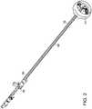
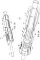
- Distal handle nose 44( FIG. 1 ) extends distally from distal handle 40 and includes flush port 46 for providing fluid communication between a solution source (not shown) and interior components of delivery device 10, as necessary, to hydrate contact between components of delivery device 10 and a vascular prosthesis (not shown) within a subject during implantation of the vascular prosthesis in the subject.
- Outer catheter 48extends from distal handle nose 44 ( FIG. 1 ).
- Actuator 80is linked to proximal handle 36, whereby proximal handle 36 can rotate about handle body 20 while push-button 82 at housing 81 of actuator 80 remains aligned with slot 84 defined by handle body 20. Depression of push-button 82 of actuator 80 selectively disengages proximal handle 36 from handle body 20, whereby rotation of proximal handle 20 is independent of longitudinal movement of delivery catheter 12 relative to handle body 20 along longitudinal axis 22.
- shifting knob 42is linked to drive gear 86 by drive shaft 88.
- Drive shaft 88has proximal end 90 and distal end 92, and runs along the interior of the handle body 20 (not shown).
- shifting knob 42is linked to drive shaft 88, in one embodiment, by intermediate gear 94A, whereby rotation of shifting knob 42 about handle body 20 causes rotation of drive shaft 88 by virtue of linkage between shifting knob 42 and drive shaft 88 by intermediate gear 94A.
- shifting knob 42is linked to drive shaft 88 indirectly, as opposed to direct linkage. "Direct linkage" would be direct contact with each other.
- Shifting knob 42is rotatably linked to distal handle 40, which is fixed to distal end 26 of handle body 20, as shown in FIG. 1 .
- linkage between shifting knob 42 and drive shaft 88includes a gear reduction at intermediate gear 94B that is linked to coaxial reduction gear 96 which, in turn, is linked to connecting gear 98 that is coaxially linked to drive shaft 88.
- gear reductionthe rate of rotation of shifting knob 42 relative to drive shaft 88 can be controlled by the relative dimensions of reduction gear 96 and connecting gear 98 ( FIGs. 5 , 6, 7 ).
- the rotation ratio, or reduction ratio, of shifting knob 42:drive shaft 88is in a ratio of between about 1:2 and about 1:6.
- the relationship between reduction gear 96 and connecting gear 98can be seen in greater detail in FIG. 6 .
- delivery catheter 28extends through handle body 20, distal handle 40 and distal handle nose 44.
- outer catheter 48is linked to base 102, whereby outer catheter 48 is rotatable independently of handle body 20.
- constricting rings 104extend along the delivery catheter 28 within handle body 20.
- constricting rings 104have an outside diameter greater than the width of slot 84, whereby constricting rings 104 will prevent application of longitudinal compressive force by proximal handle 36 on delivery catheter 28 from causing delivery catheter 28 to buckle and thereby move through slot 84 and outside of handle body 20.
- Constricting rings 104also have an inside diameter slightly less than the outside diameter of delivery catheter 28, whereby constricting rings 104 will have an interference fit with delivery catheter 28, so that constricting rings 104 can move longitudinally along delivery catheter 28 if directed, but otherwise will remain in place relative to delivery catheter 28.
- Gear rack 106extends longitudinally within handle body 20.
- Pin 108 at distal end of handle body 20extends from distal end 26 of handle body 20 and is selectively slotted within slots 110,112,114 of shifting knob 42.
- Shifting knob 42is longitudinally moveable along handle body 20 and is rotatable about handle body 20 sufficient to allow rotation of shifting knob 42 to move placement of pin 108 within any of slots 110,112,114 of shifting knob 42, which thereby causes rotation of intermediate gear 94.
- drive shaft 88rotates about longitudinal axis 116 of drive shaft 88.
- Shifting knob 42is a biased against pin 108 by spring 118 ( FIG. 7 ).
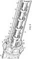
- FIG. 10shows the relation between drive shaft 88, push rod 32 and first locking mechanism 38.
- Push rod 32extends through first locking mechanism 38 which, in turn, is engaged with drive shaft 88 at drive gear 86 of first locking mechanism 38.
- First locking mechanism 38is fixed relative to proximal handle (not shown) at distal bearings 120 through which push rod 32 extends.
- Distal bearings 120are linked to first locking component housing 150 by pins 122.
- First locking component 124 of first locking mechanism 38is fixed relative to distal bearings 120 at distal end 126 and linked to drive gear 86 at proximal end 128, whereby rotation of drive shaft 88 and consequent rotation of drive gear 86 will further coil, or reduce coil, of first locking component 124, resulting in engagement or disengagement, respectively, of locking mechanism 38 and, consequently, proximal handle (not shown), with push rod 32.
- first locking mechanism 38When first locking mechanism 38 is engaged with push rod 32, longitudinal movement of proximal handle (not shown) along drive shaft 88 and, thus, handle body 20, will cause longitudinal movement of push rod 32 along drive shaft 88 and handle body 20, as can be seen by comparing FIGs. 12A and 12B .
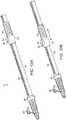
- drive shaft 88is rotatably fixed to handle body 20 ( FIG. 9 ) at driveshaft bearing 130, which is part of second proximal locking component housing 152 at proximal end 90 of drive shaft 88.
- Second locking mechanism 132includes translating gear 134 that is engaged with drive shaft 88 at proximal end 90 of the drive shaft 88 and is rotatably engaged with mechanism bearings 136 ( FIG. 11 ), including proximal bearing 138 ( FIG. 10 ) and distal bearing 140 ( FIG. 10 ) which, in turn, are fixed relative to handle body 20 at pins 142.
- Proximal bearing 138is radially and axially fixed to handle body 20.
- Distal bearing 140is axially fixed to handle body 20.
- Second locking component 144 of second locking mechanism 132is engaged with one of proximal bearing 138 at proximal end 146 of second locking component 144, and engaged with translating gear 134 at distal end 148 of second locking component 144, whereby rotation of drive shaft 88 and, consequently, rotation of translating gear 134 will tighten and engage, or loosen and disengage, second locking component 144 with push rod 32.
- second locking component 144causes push rod 32 to be fixed in location relative to handle body (not shown).
- push rod 32is longitudinally movable relative to handle body (not shown).
- first locking component 124 and second locking component 144are reversed, whereby rotation of drive shaft 88 in one direction will, simultaneously, cause engagement and disengagement of first locking component 124 and second locking component 144 with push rod 32, respectively.
- Disengagement of first locking component 124 from push rod 32is caused by movement of shifting knob 42 from a first position defined by pin 108 at slot 110 of shifting knob 42 to second position 112, defined by pin 108 at second slot 112 of shifting knob 42 ( FIG. 9 ).
- the same movement from the first to second position of shifting knob 42will simultaneously cause engagement of second locking component 144 with push rod 32, whereby push rod 32 will be fixed in position relative to handle body 20 at second locking component 144 regardless of movement of proximal handle 36 along longitudinal axis 116 of handle body 20.
- first locking component housing 150fixes lateral movement of first locking component 124 and drive shaft 88
- second locking component housing 152fixes the position of second locking component 144 and bearings 138,140 relative to proximal end 90 of drive shaft 88, respectively.
- apex release catheter 154extends within push rod 32 and guidewire catheter 12 extends within apex release catheter 154.
- FIGs. 12A and 12Bindicate relative movement of actuator 80 and proximal handle 36 along handle body 20.
- Rotation of proximal handle 36 about handle body 20, when push button 82 is in a first position, as shown in FIGs. 12A and 12Bwill cause longitudinal movement of proximal handle 20 and actuator 80 along handle body 20.
- Upon depression of push button 82 to a second position essentially flush with actuator housing 81rotation of proximal handle 36 will not cause longitudinal movement of proximal handle 36 or actuator along handle body 20. Rather, proximal handle 36 and actuator 80 will be movable along handle body 20 without rotation of proximal handle 36 about handle body 20.
- FIG. 16is a perspective view of actuator 80 of FIG. 1 (without housing 81 or pushbutton 82), of first locking component housing 150 and second locking component housing 152.
- upper pinion gear 166is coaxial with lower pinion gear 168 which, in turn, engages gear rack 106.
- delivery catheter 28is linked to first locking component housing 150 and, thus, will move longitudinally along housing 150, with movement of proximal handle 36 and actuator 80 as shown in FIG. 1 regardless of whether first locking component 124 is engaged with push rod 32. Therefore, when upper pinion gear 166 engages lower pinion gear 168, rotation of proximal handle 36 (as shown in FIG. 1 ) about handle body 20 will cause rotation of linking gear assembly 158 ( FIG. 13 ) and, consequently, rotation of pinion gear assembly 164 ( FIG. 13 ) and movement of pinion gear assembly 164 ( FIG.
- depression of center pin 170disengages upper pinion gear 166 from lower pinion gear 168.
- rotation of proximal handle 36 about handle body 20does not cause longitudinal movement of the proximal handle 36 and actuator 80 along handle body 20.
- longitudinal movement of proximal handle 36 and actuator 80 along handle body 20can be obtained simply by moving proximal handle 36 and actuator 80 along handle body 20 without rotation of proximal handle 36 about handle body 20 ( FIGs. 1 , 12A and 12B ).
- FIG. 18shows placement of the second locking component housing 152 within proximal end 24 of handle body 20 and second locking component 144 extending between bearings 138,140.
- rotation of translating gear 134by virtue of rotation of drive shaft 88 ( FIGs. 10 , 11 ) will cause engagement or disengagement of second locking component 144 with push rod 32 extending through second locking component 144 and, consequently, engagement and disengagement of push rod 32 with proximal end 24 of handle body 20.
- FIG. 19is another perspective view of linking gear assembly 158 and pinion gear assembly 164 of actuator 80 ( FIG. 1 ).
- push button 82rests atop center-pin 170, which extends through upper pinion gear 166.
- lower pinion gear 168is engaged with gear rack 106 and includes pinion gear extension 169 that is axially aligned with lower pinion gear 168 that is axially aligned with upper pinion gear 166.
- Lower portion 172 of pinion gear 168extends into opening 174 ( FIG. 11 ) defined by first locking component housing 150 ( FIG. 11 ), thereby fixing the position of pinion gear assembly 164 relative to first locking component housing 150 ( FIG. 11 ), distal bearing 120 ( FIG. 11 ), first locking component 124 and drive gear 86, all of which are shown, in a previous embodiment, in FIG. 11 .
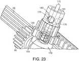
- FIG. 21is a perspective view showing engagement of lower pinion gear 168 with gear rack 106 and frustoconical portion 176 of center-pin 170.
- ball bearings 178extend through openings 180 defined by pinion gear extension 169 and, when center pin 170 is in an extended position, as shown in FIG. 22 , frustoconical portion 176 of center pin 170 forces ball bearings 178 outwardly and into interfering relation with openings 182 ( FIG. 21 ) defined by upper pinion gear 166 ( FIGs. 21 and 22 ) thereby engaging upper pinion gear 166 with lower pinion gear 168.
- depressing button 82FIG. 1
- nose cone 50is fixed to guidewire catheter 12 at a distal end 16 of the guidewire catheter 12.
- Vascular prosthetic component 58is disposed within delivery device 10 proximal to nose cone 50 ( FIG. 27A ).
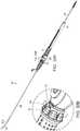
- FIGs. 25 and 26show perspective and cut-away views, respectively, of the proximal clasp assembly 184 component of the invention.
- outer coupling 186is slideable along proximal end 34 of push rod 32.
- Fixed component 188is fixed to the proximal end of the guidewire catheter by pin 192.
- Outer coupling 186 and fixed component 188are in mating relation at juncture 190.
- Spring 194 within outer coupling 186biases outer coupling 186 against fixed component 188.
- Proximal clasp assembly 184is moved from a first position, shown in FIGs.
- proximal capture component 54is no longer in mating relation with distal capture component 56.
- Proximal movement of outer coupling 186 of proximal clasp assembly 184 ( FIGs. 25 , 28B , 32B ) relative to a fixed component 188 to separate proximal capture component 54 ( FIG. 31B ) from distal capture component 56 ( FIGs. 31B , 32C )releases apices 68 of stent 66 at proximal end 60 of vascular prosthetic component 58.
- FIGs. 27A-27Care cross sectional views of a portion of delivery device 10 of the invention showing a vascular prosthetic component 58 in an undeployed state within a distal end 202 of delivery device 10.
- vascular prosthetic component 58is within delivery sheath 200.
- Distal end 62 of vascular prosthetic component 58abuts buttress 204.
- Buttress 204is mated to push rod 32 at distal end 206, proximal end 60 of vascular prosthetic component 58 captured at apices 68 of proximal stent 66 with apex clasp assembly 52 when apex clasp assembly 52 is in a closed position, as shown in FIG. 27A .
- Apex class assembly 52includes distal capture component 56 at distal end 16 of guidewire catheter 12, and proximal capture component 54 is in mateable relation to distal capture component 56, and attached to distal end 210 of apex release catheter 154.
- Apex release catheter 154extends about guidewire catheter 12, and both apex release catheter 154 and guidewire catheter 12 extend through vascular prosthetic component 58 and push rod 32 to proximal clasp assembly 184 ( FIG. 26 ).
- Delivery sheath 200is fixed at its proximal end to delivery catheter 28 at distal end 30 and extends about vascular prosthetic component 58 to apex clasp assembly 52, as can be seen in FIG. 27C .
- nose cone 50is fixed at guidewire catheter 12 distally to distal capture component 56 of apex clasp assembly 52.
- Outer catheter 48extends from distal handle nose 44 ( FIG. 1 ), and about delivery catheter 28 and delivery sheath 200, to nose cone 50.
- a method for delivering a vascular prosthesis to a treatment site of the subject employing a delivery device of the inventionincludes advancing vascular prosthesis 58, while prosthesis 58 is mounted to apex clasp assembly 52 at proximal end 60 of the prosthesis 58. Said method does not form part of the invention as claimed and is cited as an example.
- Proximal apex clasp assembly 184is in a first position shown in FIG. 28B , whereby apex clasp assembly 52 is closed ( FIG. 31B ). Apices of vascular prosthesis 58 are secured at apex clasp assembly 52 when proximal clasp assembly 184 is in the first position. Apex clasp assembly 52 is, in turn, fixed to distal end 16 of guidewire catheter 12, shifting knob 42 is in a first position when pin 108 is in slot 110 ( FIG. 28C ), causing push rod 32 to move with longitudinal movement of proximal handle 36.
- Prosthesis 58is advanced to a position distal to a vascular treatment site of the subject by rotation of proximal handle 36 in a first direction about handle body 20, having distal end 26, of delivery device 10 through which guidewire catheter 12 extends.
- Guidewire catheter 12is disposed within push rod 32 that also extends through handle body 20, wherein guidewire catheter 12 is fixed to push rod 32, such as at a proximal end of guidewire catheter 12 or push rod 32 by pin 192 ( FIG. 25 ), whereby rotation of proximal handle 36 causes longitudinal movement of guidewire catheter 12 and push rod 32 along handle body 20 to thereby at least partially advance prosthesis 58 from outer catheter 48 as can be seen in FIGs. 29A-29B .
- push button 82 of actuator 80can be depressed to disengage rotation of proximal handle 36 from longitudinal movement of proximal handle 36 along handle body 20, to thereby allow manual advancement of vascular prosthesis 58 to the vascular treatment site of the subject without rotation of proximal handle 36 about handle body 20.
- Shifting knob 42is shifted from a first position, wherein first locking component 124 ( FIGs. 10 , 11 ) secures proximal handle 36 to push rod 32, to a second position, whereby first locking component 124 ( FIGs. 10 , 11 ) disengages proximal handle 36 from push rod 32 and second locking component 144 ( FIGs. 10 , 11 ) engages push rod 32 with handle body 20 at proximal end 24 of handle body 20.
- proximal handle 36can then be rotated in a second direction, while actuator push button 82 is not depressed, whereby delivery catheter 28, having a distal end 30 ( FIG. 24A ) and extending about push rod 32, is withdrawn along push rod 32, and delivery sheath 200 extending from distal end of the delivery catheter ( FIGs. 4 through 9 ) is at least partially retracted from about prosthesis 52.
- push-button 82 of actuator 80can be depressed, thereby disengaging rotation of proximal handle 36 from handle body 20, to thereby fully retract of delivery sheath 200 from vascular prosthesis 58 without rotation of proximal handle 36 about handle body 20, as can be seen in FIG. 32A .
- Proximal clasp assembly 184is then actuated by compressing outer coupling 186 and moving outer coupling 186 first distally, then rotating outer coupling 186 ninety degrees, and thereafter retracting outer coupling 186 to a second position, shown in FIG. 32B , thereby retracting apex release catheter 154 within push rod 32 ( FIGs. 10 , 11 ) and retracting proximal capture component 54 from distal capture component 56.
- Apices 68 of stent 66 at the proximal end 60 of vascular prosthesis 58are released from apex clasp assembly 52, and prosthesis 58 is thereby released from the delivery device 10, as can be seen in FIG. 32C .
- Shifting knob 42is then moved from the second position to the third position, wherein pin 108 is located in slot 114 between first slot 110 and second slot 112, as can be seen in FIG. 33B , thereby disengaging push rod 32 from handle body 20.
- Push rod 32 and guidewire catheter 12are then withdrawn from vascular prosthesis 58 by pulling push rod 32 through handle body 20, thereby completing delivery of vascular prosthesis 58 to the treatment site, as can be seen in FIG. 33A .
Landscapes
- Health & Medical Sciences (AREA)
- Engineering & Computer Science (AREA)
- Biomedical Technology (AREA)
- Cardiology (AREA)
- Oral & Maxillofacial Surgery (AREA)
- Transplantation (AREA)
- Heart & Thoracic Surgery (AREA)
- Vascular Medicine (AREA)
- Life Sciences & Earth Sciences (AREA)
- Animal Behavior & Ethology (AREA)
- General Health & Medical Sciences (AREA)
- Public Health (AREA)
- Veterinary Medicine (AREA)
- Media Introduction/Drainage Providing Device (AREA)
- Surgical Instruments (AREA)
Description
- An aortic aneurysm is an enlargement or bulge in a section of the aorta, which can be life-threatening. Treatment of aortic aneurysms remain a challenge. Endovascular repair has become a viable alternative to open repair of an aortic aneurysm. An endovascular approach results in insertion of an endovascular graft to exclude the aneurysm sac from blood flow. Once in place, the endovascular graft is expanded to create a new path for blood flow. The endovascular graft remains inside the aorta permanently through the use of a metal stent creating a tight fit and seal against the wall of the aorta. Currently, endovascular delivery devices have limitations on the precise control that the physician has in placement of the graft at the site of the aneurysm. Thus, there is a need to develop new and improved delivery devices and methods of using delivery devices to treat aortic aneurysms.
EP1982677A2 discloses the preamble ofclaim 1 and a delivery system for stent-graft.- The invention is generally directed to a delivery device for implanting a vascular prosthesis, as disclosed in the appended claims, and discloses as an example a method of use of the delivery device.
- In one embodiment, the delivery device includes a guidewire catheter having a proximal end and a distal end, and a delivery assembly extending about the guidewire catheter. The delivery assembly includes a handle body, a delivery catheter, a push rod, a proximal handle and a locking mechanism. The handle body has a major longitudinal axis, a proximal end and a distal end. The delivery catheter has a distal end extending from within the distal end of the handle body and about the guidewire catheter. The push rod extends about the guidewire catheter and within the delivery catheter. The push rod is fixed to the guidewire catheter at a proximal end of the guidewire catheter proximal to the handle body. The proximal handle extends about the handle body and is axially fixed to the delivery catheter, wherein the proximal handle is selectively fixed to the push rod, and wherein the proximal handle is rotatable about the handle body and rotation of the proximal handle about the handle body translates to longitudinal movement of the delivery catheter and, selectively, of the push rod relative to the handle body. The locking mechanism at the handle body selectively engages the proximal handle with the push rod.
- In an embodiment, the delivery device includes an actuator at the proximal handle that selectively disengages the proximal handle from the handle body, whereby rotation of the proximal handle is independent of longitudinal movement of the delivery catheter relative to the handle body. In another embodiment, the proximal handle includes an end that defines teeth that move transversely to a major longitudinal axis of the handle body when the proximal handle is rotated about the handle body. In this embodiment, the delivery device further includes a gear rack extending along the major longitudinal axis of the handle body, a linking gear engaging the teeth of the proximal handle end, the linking gear being rotatable about an axis transverse to the axis of rotation of the proximal handle, and a pinion gear. The pinion gear engages the gear rack and the linking gear, whereby rotation of the proximal handle about the handle body translates to the longitudinal movement of the delivery catheter and, selectively, of the push rod relative to the handle body. The actuator selectively disengages the linking gear from the pinion gear, thereby selectively disengaging rotation of the proximal handle from longitudinal movement of the proximal handle along the handle body.
- In still another embodiment, the actuator of the delivery device includes an actuator housing, a push-button, a pinion gear extension, a ball bearing and a frustoconical center-pin. The actuator housing extends about the handle body and is rotatably linked to the proximal handle, whereby the actuator housing is movable along the handle body without rotating about the handle body while the proximal handle rotates about the handle body. The push-button is located at the actuator housing. The pinion gear extension defines a coaxial opening that is coaxial with the pinion gear and defines at least one lateral opening that extends laterally from the coaxial opening. The ball-bearing sits at least partially within the lateral opening and locks the relative rotation of the linking gear and the pinion gear when displaced to extend radially beyond the pinion gear extension. The frustoconical center-pin is biased radially outward from the major longitudinal axis of the handle body and abuts the push-button, whereby the frustoconical center-pin displaces the ball bearing radially outward through the lateral opening and locks the relative rotation of the linking gear and the pinion gear by the outward bias, thereby causing longitudinal movement of the proximal handle along the handle body when the proximal handle is rotated about the handle body and, when the push-button is depressed, selectively disengages the linking gear from pinion gear, thereby selectively disengaging rotation of the proximal handle from the longitudinal movement of the proximal handle along the handle body.
- Another embodiment of the delivery device of the invention includes a distal grip at the distal end of the handle body, and the locking mechanism includes a shifting knob, a drive shaft, a drive gear and a first locking component. The shifting knob is located at the distal grip and is rotatable about the handle body and defines teeth along the inside of the shifting knob that move transversely to the major longitudinal axis of the handle body when the shifting knob is rotated about the handle body. The locking mechanism has at least two fixed positions relative to the handle body. The drive shaft has a proximal end and a distal end, wherein the distal end defines teeth that engage directly or indirectly, the teeth of the shifting knob, and extend along a major longitudinal axis of the driveshaft. The drive gear is along the drive shaft and defines teeth that engage, directly or indirectly, the teeth along the drive shaft, whereby the shifting knob is engaged with the drive gear at all positions of the shifting knob. The first locking component extends about the push rod and is linked to the proximal handle and the drive gear, whereby, in a first position of the shifting knob, the first locking component engages the proximal handle with the push rod, and rotation of the shifting knob from the first position to a second position causes rotation of the drive shaft which, in turn, causes rotation of the drive gear and disengagement of the first locking component from the push rod, thereby allowing independent movement of the delivery catheter along the longitudinal axis of the handle body relative to the push rod when the proximal handle is moved along major longitudinal axis of the handle body.
- In another embodiment of the invention, the locking mechanism further includes a second locking component. The second locking component extends about the push rod, is fixed to the handle body, and is linked to the shifting knob through the drive shaft, whereby rotation of the shifting knob from the first position to the second position causes engagement between the handle body and the push rod, thereby preventing longitudinal movement of the push rod relative to the handle body when the proximal handle is moved along the major longitudinal axis.
- In yet another embodiment, the delivery device of the invention includes an apex delivery device that includes an apex clasp assembly and proximal clasp assembly. The apex clasp assembly includes a distal capture component at a distal end of the guidewire catheter, a proximal capture component in mateable relation to the distal capture component, and an apex release catheter having a proximal end, wherein the apex release catheter extends about the guidewire catheter and is fixed to the proximal capture component. The proximal clasp assembly includes a fixed component at the proximal end of the guidewire catheter and an outer coupling at the proximal end at the apex release catheter in mateable relation with the fixed component of the proximal clasp assembly, whereby movement of the outer coupling relative to the fixed component from a first position to a second position will cause relative movement of the proximal capture component relative to the distal capture component of the apex clasp assembly.
- In still another embodiment, the invention includes the delivery device that includes a gear rack, a handle extending about the gear rack and defining teeth at an end of the handle, the handle being rotatable about the gear rack, a pinion gear that is rotatable about an axis that intersects with the axis of rotation of the handle and engages the gear rack, a linking gear that selectively rotates with rotation of the pinion gear, an actuator that selectively engages the pinion gear with the linking gear, and a delivery catheter fixed to the handle, whereby rotation of the handle selectively moves a delivery catheter relative to the gear rack upon engagement of the pinion gear with the linking gear by the actuator.
- An example (not forming part of the invention as claimed) discloses a method for delivering a vascular prosthesis to a treatment site of a subject. The method includes advancing the vascular prosthesis, while mounted at a proximal end of the prosthesis to an apex delivery device fixed to a distal end of a guidewire catheter, to a position distal to a vascular treatment site of the subject. A proximal handle is rotated in a first direction about a handle body, having a distal end, of a delivery device through which the guidewire catheter extends. The guidewire catheter is disposed within a push rod that also extends through the handle body, wherein the guidewire catheter is fixed to the push rod, whereby rotation of the proximal handle causes longitudinal movement of the guidewire catheter and the push rod along the handle body to thereby at least partially advance the prosthesis to the treatment site, the prosthesis being advanced from within an outer catheter extending from a distal end of the handle body and about the prosthesis. The position of a first locking component securing the proximal handle to the push rod is shifted from a first position to a second position, wherein the first locking component disengages the proximal handle from the push rod and a second locking component engages the push rod with the handle body. The proximal handle is then rotated in a second direction, whereby a delivery catheter, having a distal end and extending about the push rod, is withdrawn along the push rod, and a delivery sheath extending from the distal end of the delivery catheter is at least partially retracted from about the prosthesis. The proximal end of the prosthesis is then released from the apex delivery device. The second locking component is shifted to disengage the push rod from the handle body, and the push rod and the guidewire catheter are withdrawn from within the prosthesis, thereby delivering the vascular prosthesis to the treatment site.
- The delivery device of the invention have many advantages. For example, rotation of the proximal handle to thereby advance the push rod and a vascular prosthesis at the end of the push rod provides increased control over movement of the vascular prosthesis during implantation at a treatment site. Further, selective engagement of the proximal handle and the push rod enables disengagement of the proximal handle from the push rod to thereby provide for controlled retraction of a delivery sheath from the vascular prosthesis by rotation of the proximal handle in an opposite direction to that which is employed to advance the vascular prosthesis to the treatment site. In addition, an actuator of the delivery device enables selective disengagement of the proximal handle from the handle body, whereby the proximal handle can be moved along the handle body without rotation of the proximal handle, thereby providing another degree of freedom of movement of the vascular prosthesis during advancement of the vascular prosthesis to the treatment site and during retraction of the delivery sheath from the prosthesis once the prosthesis has been advanced to the treatment site. The delivery device of the invention also has the advantage of causing engagement of the push rod with the handle body upon disengagement of the proximal handle from the push rod, thereby enabling withdrawal of the delivery sheath from the vascular prosthesis without entrainment of the vascular prosthesis while the delivery sheath is being retracted from the vascular prosthesis by movement of the proximal handle. Further, the apex delivery device is controllable at a proximal end of the push rod and guidewire catheter, thereby enabling selective release of a proximal end of the vascular prosthesis at the treatment site while remaining components of the delivery device remain stationary. In addition, the push rod can be disengaged from both the handle body and the proximal handle, thereby enabling retraction of the push rod, guidewire catheter and apex delivery device from within the vascular prosthesis once it has been implanted at the delivery device, thereby minimizing potential disruption of the vascular prosthesis once it has been implanted.
FIG. 1 is a perspective view of one embodiment of the delivery device of the invention.FIG. 2 is a perspective view of one embodiment of a shifting knob, driveshaft and actuator, of the invention.FIG. 3 is a perspective view of the shifting knob and driveshaft of the embodiment shown inFIG. 2 .FIG. 4 is a perspective view of a shifting knob, distal handle, distal handle nose, and a cross-sectional view, in part, of a handle body and delivery catheter of another embodiment of the invention.FIG. 5 is a partial cutaway section of the portion of the embodiment of the delivery device of the invention shown inFIG. 4 .FIG. 6 is a partial cutaway section of a detail of a portion of the handle body, intermediate gear, reduction gear and connecting gear, all of which link the shifting knob with the driveshaft of the embodiment of the invention shown inFIG. 4 .FIG. 7 is a partial cutaway view of the embodiment ofFIG. 4 , showing a cross-sectional view of the distal handle and a base to which outer catheter is connected at distal handle nose.FIG. 8 is a partial cutaway, of the embodiment ofFIG. 4 showing constricting rings extending about a delivery catheter.FIG. 9 is another embodiment of a partial cutaway of the delivery device ofFIG. 1 showing an actuator and a push button at the proximal end of a slot defined by the handle body.FIG. 10 is a perspective view of first locking component, and second locking component, and their relation to the drive shaft of the embodiment shown inFIG. 1 .FIG. 11 is another representation of a first locking component and a second locking component, and a first locking component housing and a second locking component housing stabilizing the spatial relation between the first locking component and the second locking component, respectively, relative to the drive shaft of the embodiment ofFIG. 1 .FIG. 12A is another perspective view of the embodiment ofFIG. 1 , showing displacement of the proximal handle and the actuator along the handle body consequent to rotating of the proximal handle about the handle body or depressing the push button of the actuator to thereby allow longitudinal movement of the actuator and the proximal handle without rotation of the proximal handle.FIG. 12B is another perspective view of the embodiment ofFIG. 1 , wherein a proximal handle has been advanced along the handle body of the delivery system.FIG. 13 is a detail of the proximal handle and the actuator at the handle body of the embodiment of the invention shown inFIG. 1 , without the actuator housing.FIG. 14 is a perspective view of the detail ofFIG. 13 , without the push button of the actuator shown inFIG. 13 .FIG. 15 is a partial cutaway of the embodiment ofFIG. 1 showing the relation of the pinion and the linking gear assemblies relative to the first locking component housing and the relationship of the first locking component housing to the delivery catheter within the housing.FIG. 16 is a perspective view of the first locking component housing and the second locking component housing within a cutaway view of the handle body, along with a perspective view of the linking gear assembly and the pinion gear assembly of the actuator.FIG. 17 is a side view of the representation of the invention, as shown inFIG. 16 .FIG. 18 is a partial cutaway of the distal end of handle body and second locking component shown inFIGs. 16 and 17 .FIG. 19 is a perspective view of a partial cutaway of the actuator shown inFIG. 17 .FIG. 20 is a perspective view of a rack and proximal handle of the embodiment shown inFIG. 1 , and an alternate embodiment of the actuator of the invention, lacking a linking gear assembly.FIG. 21 is a perspective view, partially transparent, of the embodiment of the pinion gear assembly ofFIG. 20 .FIG. 22 is another view of the embodiment represented inFIG. 21 .FIG. 23 is a perspective view of the embodiment shown inFIGs. 21 and22 , lacking the upper pinion gear shown in those figures.FIG. 24 is another embodiment of the representation shown inFIG. 23 .FIG. 25 is a perspective view of one embodiment of a proximal clasp assembly of one embodiment of the invention.FIG. 26 is a partial cutaway of the proximal clasp assembly shown inFIG. 25 .FIGs. 27A-27C are perspective sectional views of the distal end of the delivery device shown inFIG. 1 .FIG. 28A is a perspective view of the shifting knob in the first position, wherein the push rod is fixed to the proximal handle and the prosthesis is undeployed.FIG. 28B is a detailed perspective view of proximal clasp assembly in a first position, whereby the apex clasp assembly is unopened.FIG. 28C is a detailed perspective view of the shifting knob in the first position.FIG. 29A is a perspective view of the delivery device ofFIGs. 28A-28C showing advancement of the delivery sheath containing the prosthesis when the shifting knob is in a second position, wherein the push rod is fixed to the handle body.FIG. 29B is a detailed perspective view of advancement of the delivery sheath ofFIG. 29A .FIG. 30A is a perspective view of the delivery device ofFIGs. 29A, 29B showing advancement of the delivery sheath.FIG. 30B is a detailed perspective view of the shifting knob ofFIG. 30A in a second position.FIG. 31A is a perspective view of the delivery device ofFIGs. 30A, 30B , wherein the delivery sheath has been partially retracted from the prosthesis.FIG. 31B is a representation of an apex clasp assembly of one embodiment of the invention in a closed position.FIG. 32A is a perspective view of the delivery device ofFIG. 31A , wherein the apex clasp assembly is opened by actuation of the proximal clasp assembly to thereby release the apices of the proximal stent of the prosthesis shown inFIG. 32C .FIG. 32B is a representation of the proximal clasp assembly ofFIGs. 25, 26 , whereby an apex clasp assembly, not shown, has been opened.FIG. 32C is a representation of the apex clasp assembly of one embodiment of the invention, in an open position.FIG. 33A is a perspective view of the delivery device ofFIG. 32A , wherein the shifting knob has been moved to the third position, whereby the push rod has been released from the proximal handle and the handle body and, wherein the push rod has been retracted from the fully deployed prosthesis.FIG. 33B is a perspective view of the shifting knob in the third position as shown inFIG. 33A .- While this invention has been particularly shown and described with references to example embodiments thereof, it will be understood by those skilled in the art that various changes in form and details may be made therein without departing from the scope of the invention encompassed by the appended claims.
- One embodiment, of the
delivery device 10 of the invention is shown inFIG. 1 .Delivery device 10 includes guidewire catheter 12 (FIGs. 10 ,11 ) having a proximal end and a distal end. "Proximal," as a term employed herein with reference to the delivery device and its components, means relatively close to the surgeon operating the delivery device. "Distal," as a term employed herein with reference to the delivery device and its components, means relatively distal from the surgeon operating the delivery device. "Proximal," as a term employed herein with reference to the prosthesis, stent-graft and components, means relatively close to the heart of the patient. "Distal," as a term employed herein with reference to the prosthesis, stent-graft and components, means relatively distal from the heart of the patient. Returning toFIG. 1 ,delivery device 10 includesdelivery assembly 18 that extends about the guidewire catheter (not shown).Delivery assembly 18 includeshandle body 20 having majorlongitudinal axis 22,proximal end 24 anddistal end 26. Delivery catheter 28 (FIG. 9 ) has distal end 30 (FIG. 27A ) extending from withindistal end 26 ofhandle body 20 and about the guidewire catheter (not shown). Pushrod 32 extends aboutguidewire catheter 12 and within delivery catheter 28 (FIGs. 10 ,11 ). Pushrod 32 is fixed toguidewire catheter 12 atproximal end 34 ofpush rod 32 proximal to the handle body at pin 192 (FIG. 25 ). Referring back toFIG. 1 ,proximal handle 36 extends abouthandle body 20 and is axially fixed todelivery catheter 28.Proximal handle 36 is selectively fixed to pushrod 32, whereinproximal handle 36 is rotatable abouthandle body 20 and rotation ofproximal handle 36 abouthandle body 20 translates to longitudinal movement ofdelivery catheter 28 alonglongitudinal axis 22 and, selectively, ofpush rod 32 relative to handlebody 20, as can be seen by comparingFIGs. 12A withFIG. 12B . First locking mechanism 38 (FIG. 15 ) athandle body 20 selectively engages proximal handle 36 (FIGs. 12A and 12B ) withpush rod 32. Distal handle 40 extends abouthandle body 20 atdistal end 26 ofhandle body 20 and is distal to shiftingknob 42 of first locking mechanism 38 ((FIG. 15 ). Distal handle nose 44 (FIG. 1 ) extends distally fromdistal handle 40 and includesflush port 46 for providing fluid communication between a solution source (not shown) and interior components ofdelivery device 10, as necessary, to hydrate contact between components ofdelivery device 10 and a vascular prosthesis (not shown) within a subject during implantation of the vascular prosthesis in the subject.Outer catheter 48 extends from distal handle nose 44 (FIG. 1 ).Actuator 80 is linked toproximal handle 36, wherebyproximal handle 36 can rotate abouthandle body 20 while push-button 82 athousing 81 ofactuator 80 remains aligned withslot 84 defined byhandle body 20. Depression of push-button 82 ofactuator 80 selectively disengagesproximal handle 36 fromhandle body 20, whereby rotation ofproximal handle 20 is independent of longitudinal movement ofdelivery catheter 12 relative to handlebody 20 alonglongitudinal axis 22.- As can be seen in
FIG. 2 , shiftingknob 42 is linked to drivegear 86 bydrive shaft 88. Driveshaft 88 hasproximal end 90 anddistal end 92, and runs along the interior of the handle body 20 (not shown). As can be seen inFIG. 3 , shiftingknob 42 is linked to driveshaft 88, in one embodiment, byintermediate gear 94A, whereby rotation of shiftingknob 42 abouthandle body 20 causes rotation ofdrive shaft 88 by virtue of linkage between shiftingknob 42 and driveshaft 88 byintermediate gear 94A. In this embodiment, shiftingknob 42 is linked to driveshaft 88 indirectly, as opposed to direct linkage. "Direct linkage" would be direct contact with each other. Shiftingknob 42 is rotatably linked todistal handle 40, which is fixed todistal end 26 ofhandle body 20, as shown inFIG. 1 . - In another embodiment, shown in
FIGs. 4 and 5 , linkage between shiftingknob 42 and driveshaft 88 includes a gear reduction atintermediate gear 94B that is linked tocoaxial reduction gear 96 which, in turn, is linked to connectinggear 98 that is coaxially linked to driveshaft 88. By virtue of the gear reduction, the rate of rotation of shiftingknob 42 relative to driveshaft 88 can be controlled by the relative dimensions ofreduction gear 96 and connecting gear 98 (FIGs. 5 ,6, 7 ). Typically, the rotation ratio, or reduction ratio, of shifting knob 42:driveshaft 88 is in a ratio of between about 1:2 and about 1:6. The relationship betweenreduction gear 96 and connectinggear 98 can be seen in greater detail inFIG. 6 . - As can be seen in greater detail in
FIG. 7 ,delivery catheter 28 extends throughhandle body 20,distal handle 40 anddistal handle nose 44. Referring back toFIG. 5 ,outer catheter 48 is linked tobase 102, wherebyouter catheter 48 is rotatable independently ofhandle body 20. As shown inFIG. 8 , constrictingrings 104 extend along thedelivery catheter 28 withinhandle body 20. As shown inFIGs. 8 and9 , constrictingrings 104 have an outside diameter greater than the width ofslot 84, whereby constricting rings 104 will prevent application of longitudinal compressive force byproximal handle 36 ondelivery catheter 28 from causingdelivery catheter 28 to buckle and thereby move throughslot 84 and outside ofhandle body 20. Constricting rings 104 also have an inside diameter slightly less than the outside diameter ofdelivery catheter 28, whereby constricting rings 104 will have an interference fit withdelivery catheter 28, so that constrictingrings 104 can move longitudinally alongdelivery catheter 28 if directed, but otherwise will remain in place relative todelivery catheter 28.Gear rack 106 extends longitudinally withinhandle body 20.Pin 108 at distal end ofhandle body 20 extends fromdistal end 26 ofhandle body 20 and is selectively slotted within slots 110,112,114 of shiftingknob 42. Shiftingknob 42 is longitudinally moveable alonghandle body 20 and is rotatable abouthandle body 20 sufficient to allow rotation of shiftingknob 42 to move placement ofpin 108 within any of slots 110,112,114 of shiftingknob 42, which thereby causes rotation ofintermediate gear 94. As a consequence, driveshaft 88 rotates aboutlongitudinal axis 116 ofdrive shaft 88. Shiftingknob 42 is a biased againstpin 108 by spring 118 (FIG. 7 ). - As can be seen in
FIG. 9 ,gear rack 106 and driveshaft 88 extend the length ofslot 84.FIG. 10 shows the relation betweendrive shaft 88,push rod 32 andfirst locking mechanism 38. Pushrod 32 extends throughfirst locking mechanism 38 which, in turn, is engaged withdrive shaft 88 atdrive gear 86 offirst locking mechanism 38.First locking mechanism 38 is fixed relative to proximal handle (not shown) atdistal bearings 120 through which pushrod 32 extends.Distal bearings 120 are linked to firstlocking component housing 150 bypins 122.First locking component 124 offirst locking mechanism 38 is fixed relative todistal bearings 120 atdistal end 126 and linked to drivegear 86 atproximal end 128, whereby rotation ofdrive shaft 88 and consequent rotation ofdrive gear 86 will further coil, or reduce coil, offirst locking component 124, resulting in engagement or disengagement, respectively, of lockingmechanism 38 and, consequently, proximal handle (not shown), withpush rod 32. Whenfirst locking mechanism 38 is engaged withpush rod 32, longitudinal movement of proximal handle (not shown) alongdrive shaft 88 and, thus, handlebody 20, will cause longitudinal movement ofpush rod 32 alongdrive shaft 88 and handlebody 20, as can be seen by comparingFIGs. 12A and 12B . - Referring back to
FIGs. 10 ,11 ,drive shaft 88 is rotatably fixed to handle body 20 (FIG. 9 ) at driveshaft bearing 130, which is part of second proximallocking component housing 152 atproximal end 90 ofdrive shaft 88.Second locking mechanism 132 includes translatinggear 134 that is engaged withdrive shaft 88 atproximal end 90 of thedrive shaft 88 and is rotatably engaged with mechanism bearings 136 (FIG. 11 ), including proximal bearing 138 (FIG. 10 ) and distal bearing 140 (FIG. 10 ) which, in turn, are fixed relative to handlebody 20 atpins 142.Proximal bearing 138 is radially and axially fixed to handlebody 20.Distal bearing 140 is axially fixed to handlebody 20.Second locking component 144 ofsecond locking mechanism 132 is engaged with one ofproximal bearing 138 atproximal end 146 ofsecond locking component 144, and engaged with translatinggear 134 atdistal end 148 ofsecond locking component 144, whereby rotation ofdrive shaft 88 and, consequently, rotation of translatinggear 134 will tighten and engage, or loosen and disengage,second locking component 144 withpush rod 32. When engaged withpush rod 32,second locking component 144 causes pushrod 32 to be fixed in location relative to handle body (not shown). When loosened and disengaged frompush rod 32,push rod 32 is longitudinally movable relative to handle body (not shown). The orientation offirst locking component 124 andsecond locking component 144 are reversed, whereby rotation ofdrive shaft 88 in one direction will, simultaneously, cause engagement and disengagement offirst locking component 124 andsecond locking component 144 withpush rod 32, respectively. Disengagement offirst locking component 124 frompush rod 32 is caused by movement of shiftingknob 42 from a first position defined bypin 108 atslot 110 of shiftingknob 42 tosecond position 112, defined bypin 108 atsecond slot 112 of shifting knob 42 (FIG. 9 ). The same movement from the first to second position of shiftingknob 42 will simultaneously cause engagement ofsecond locking component 144 withpush rod 32, wherebypush rod 32 will be fixed in position relative to handlebody 20 atsecond locking component 144 regardless of movement ofproximal handle 36 alonglongitudinal axis 116 ofhandle body 20. Referring back toFIGs. 8 and9 , positioning shiftingknob 42, so thatpin 108 is atintermediate slot 114 between thefirst slot 110 andsecond slot 112 of shiftingknob 42, will cause bothfirst locking component 124 andsecond locking component 144 to be disengaged frompush rod 32. - As can be seen in
FIG. 11 , firstlocking component housing 150 fixes lateral movement offirst locking component 124 and driveshaft 88, and secondlocking component housing 152 fixes the position ofsecond locking component 144 and bearings 138,140 relative toproximal end 90 ofdrive shaft 88, respectively. Further, as can also be seen inFIG. 11 ,apex release catheter 154 extends withinpush rod 32 andguidewire catheter 12 extends withinapex release catheter 154. FIGs. 12A and 12B indicate relative movement ofactuator 80 andproximal handle 36 alonghandle body 20. Rotation ofproximal handle 36 abouthandle body 20, whenpush button 82 is in a first position, as shown inFIGs. 12A and 12B , will cause longitudinal movement ofproximal handle 20 andactuator 80 alonghandle body 20. Upon depression ofpush button 82 to a second position essentially flush withactuator housing 81, rotation ofproximal handle 36 will not cause longitudinal movement ofproximal handle 36 or actuator alonghandle body 20. Rather,proximal handle 36 andactuator 80 will be movable alonghandle body 20 without rotation ofproximal handle 36 abouthandle body 20.- As can be seen in
FIGs. 13-15 ,teeth 156 ofproximal handle 36 engageupper linking gear 160 of linkinggear assembly 158. Linkinggear assembly 158 is engaged withpinion gear assembly 164.Lower linking gear 162 of linkinggear assembly 158 engagesupper pinion gear 166 ofpinion gear assembly 164.Pinion gear assembly 164 is linked to first locking component housing 150 (FIG. 11 ) throughslot 84. Linkinggear assembly 158 andpinion gear assembly 164 are components ofactuator 80, referenced with respect toFIG. 1 .FIG. 16 is a perspective view ofactuator 80 ofFIG. 1 (withouthousing 81 or pushbutton 82), of firstlocking component housing 150 and secondlocking component housing 152. - As can be seen in
FIG. 17 ,upper pinion gear 166 is coaxial withlower pinion gear 168 which, in turn, engagesgear rack 106. Referring back toFIGs. 16 and 17 ,delivery catheter 28 is linked to firstlocking component housing 150 and, thus, will move longitudinally alonghousing 150, with movement ofproximal handle 36 andactuator 80 as shown inFIG. 1 regardless of whetherfirst locking component 124 is engaged withpush rod 32. Therefore, whenupper pinion gear 166 engageslower pinion gear 168, rotation of proximal handle 36 (as shown inFIG. 1 ) abouthandle body 20 will cause rotation of linking gear assembly 158 (FIG. 13 ) and, consequently, rotation of pinion gear assembly 164 (FIG. 13 ) and movement of pinion gear assembly 164 (FIG. 13 ) along gear rack 106 (FIGs. 16 and 17 ), and movement of proximal handle 36 (FIG. 1 ) and actuator 80 (FIG. 17 ) alonghandle body 20. Further, whilefirst locking component 124 is engaged withpush rod 32, rotation ofproximal handle 36 will cause longitudinal movement ofpush rod 32 alonghandle body 20. In all cases, movement ofproximal handle 36 andactuator 80 alonghandle body 20 will always occur together, and will cause movement ofdelivery catheter 28 longitudinally alonghandle body 20. - However, as will be further explained below, depression of
center pin 170 disengagesupper pinion gear 166 fromlower pinion gear 168. Whenupper pinion gear 166 is disengaged fromlower pinion gear 168, rotation ofproximal handle 36 abouthandle body 20 does not cause longitudinal movement of theproximal handle 36 andactuator 80 alonghandle body 20. Further, longitudinal movement ofproximal handle 36 andactuator 80 alonghandle body 20 can be obtained simply by movingproximal handle 36 andactuator 80 alonghandle body 20 without rotation ofproximal handle 36 about handle body 20 (FIGs. 1 ,12A and 12B ). FIG. 18 shows placement of the secondlocking component housing 152 withinproximal end 24 ofhandle body 20 andsecond locking component 144 extending between bearings 138,140. As stated above, rotation of translatinggear 134 by virtue of rotation of drive shaft 88 (FIGs. 10 ,11 ) will cause engagement or disengagement ofsecond locking component 144 withpush rod 32 extending throughsecond locking component 144 and, consequently, engagement and disengagement ofpush rod 32 withproximal end 24 ofhandle body 20.FIG. 19 is another perspective view of linkinggear assembly 158 andpinion gear assembly 164 of actuator 80 (FIG. 1 ).- As an alternative embodiment, shown in
FIG. 20 ,push button 82 rests atop center-pin 170, which extends throughupper pinion gear 166. As can also be seen inFIGs. 20 and21 ,lower pinion gear 168 is engaged withgear rack 106 and includespinion gear extension 169 that is axially aligned withlower pinion gear 168 that is axially aligned withupper pinion gear 166.Lower portion 172 ofpinion gear 168 extends into opening 174 (FIG. 11 ) defined by first locking component housing 150 (FIG. 11 ), thereby fixing the position ofpinion gear assembly 164 relative to first locking component housing 150 (FIG. 11 ), distal bearing 120 (FIG. 11 ),first locking component 124 and drivegear 86, all of which are shown, in a previous embodiment, inFIG. 11 . FIG. 21 is a perspective view showing engagement oflower pinion gear 168 withgear rack 106 andfrustoconical portion 176 of center-pin 170. As can be seen inFIGs. 22 and23 ,ball bearings 178 extend throughopenings 180 defined bypinion gear extension 169 and, whencenter pin 170 is in an extended position, as shown inFIG. 22 ,frustoconical portion 176 ofcenter pin 170forces ball bearings 178 outwardly and into interfering relation with openings 182 (FIG. 21 ) defined by upper pinion gear 166 (FIGs. 21 and22 ) thereby engagingupper pinion gear 166 withlower pinion gear 168. Whencenter pin 170 is actuated by depressing button 82 (FIG. 1 ), as shown inFIG. 23 ,ball bearings 178 are forced inward by rotation of upper pinion gear 166 (FIG. 22 ) relative to lower pinion gear 168 (FIG. 22 ), wherebyupper pinion gear 166 is no longer engaged withlower pinion gear 168. Center-pin 170 is biased in an outward position, wherebyupper pinion gear 166 is directed into engagement withlower pinion gear 168 byspring 184 located at the base of center pin 170 (not shown inFIG. 22 or23 ).- As can be seen in
FIG. 32C ,nose cone 50 is fixed toguidewire catheter 12 at adistal end 16 of theguidewire catheter 12. Vascularprosthetic component 58 is disposed withindelivery device 10 proximal to nose cone 50 (FIG. 27A ). FIGs. 25 and 26 show perspective and cut-away views, respectively, of theproximal clasp assembly 184 component of the invention. As can be seen inFIG. 25 ,outer coupling 186 is slideable alongproximal end 34 ofpush rod 32.Fixed component 188 is fixed to the proximal end of the guidewire catheter bypin 192.Outer coupling 186 and fixedcomponent 188 are in mating relation atjuncture 190.Spring 194 withinouter coupling 186 biasesouter coupling 186 against fixedcomponent 188.Proximal clasp assembly 184 is moved from a first position, shown inFIGs. 25 ,28B to a second position, shown by applying pressure totongues 196 on either side ofouter coupling 186, and directingouter coupling 186 distally in sufficient degree to allow rotation ofouter coupling 186 ninety (90) degrees and then retractingouter coupling 186 so thattongues 196 ofouter coupling 186 align betweentongues 198 of fixedcomponent 188, as shown inFIG. 32B . Movement ofouter coupling 186 from the first position, shown inFIG. 25 , to the position shown inFIG. 32B , causes opening ofapex clasp assembly 52, whereby proximal capture component is retracted from a first position that is in mating relation to thedistal capture component 56 ofapex clasp assembly 52 shown inFIG. 31B , to a second position, shown inFIG. 32C , whereinproximal capture component 54 is no longer in mating relation withdistal capture component 56. Proximal movement ofouter coupling 186 of proximal clasp assembly 184 (FIGs. 25 ,28B ,32B ) relative to a fixedcomponent 188 to separate proximal capture component 54 (FIG. 31B ) from distal capture component 56 (FIGs. 31B ,32C ) releasesapices 68 ofstent 66 atproximal end 60 of vascularprosthetic component 58.FIGs. 27A-27C are cross sectional views of a portion ofdelivery device 10 of the invention showing a vascularprosthetic component 58 in an undeployed state within adistal end 202 ofdelivery device 10. Specifically, as shown inFIG. 27A , vascularprosthetic component 58 is withindelivery sheath 200.Distal end 62 of vascularprosthetic component 58 abuts buttress 204.Buttress 204, in turn, is mated to pushrod 32 atdistal end 206,proximal end 60 of vascularprosthetic component 58 captured atapices 68 ofproximal stent 66 withapex clasp assembly 52 whenapex clasp assembly 52 is in a closed position, as shown inFIG. 27A .Apex class assembly 52 includesdistal capture component 56 atdistal end 16 ofguidewire catheter 12, andproximal capture component 54 is in mateable relation todistal capture component 56, and attached todistal end 210 ofapex release catheter 154.Apex release catheter 154 extends aboutguidewire catheter 12, and bothapex release catheter 154 andguidewire catheter 12 extend through vascularprosthetic component 58 and pushrod 32 to proximal clasp assembly 184 (FIG. 26 ).Delivery sheath 200 is fixed at its proximal end todelivery catheter 28 atdistal end 30 and extends about vascularprosthetic component 58 toapex clasp assembly 52, as can be seen inFIG. 27C . Returning toFIG. 27 ,nose cone 50 is fixed atguidewire catheter 12 distally todistal capture component 56 ofapex clasp assembly 52.Outer catheter 48 extends from distal handle nose 44 (FIG. 1 ), and aboutdelivery catheter 28 anddelivery sheath 200, tonose cone 50.- As shown in
FIGs. 28A-33B , a method for delivering a vascular prosthesis to a treatment site of the subject employing a delivery device of the invention includes advancingvascular prosthesis 58, whileprosthesis 58 is mounted toapex clasp assembly 52 atproximal end 60 of theprosthesis 58. Said method does not form part of the invention as claimed and is cited as an example. - Proximal
apex clasp assembly 184 is in a first position shown inFIG. 28B , wherebyapex clasp assembly 52 is closed (FIG. 31B ). Apices ofvascular prosthesis 58 are secured atapex clasp assembly 52 whenproximal clasp assembly 184 is in the first position.Apex clasp assembly 52 is, in turn, fixed todistal end 16 ofguidewire catheter 12, shiftingknob 42 is in a first position whenpin 108 is in slot 110 (FIG. 28C ), causingpush rod 32 to move with longitudinal movement ofproximal handle 36.Prosthesis 58 is advanced to a position distal to a vascular treatment site of the subject by rotation ofproximal handle 36 in a first direction abouthandle body 20, havingdistal end 26, ofdelivery device 10 through whichguidewire catheter 12 extends.Guidewire catheter 12 is disposed withinpush rod 32 that also extends throughhandle body 20, whereinguidewire catheter 12 is fixed to pushrod 32, such as at a proximal end ofguidewire catheter 12 or pushrod 32 by pin 192 (FIG. 25 ), whereby rotation ofproximal handle 36 causes longitudinal movement ofguidewire catheter 12 and pushrod 32 alonghandle body 20 to thereby at least partially advanceprosthesis 58 fromouter catheter 48 as can be seen inFIGs. 29A-29B . Optionally,push button 82 ofactuator 80 can be depressed to disengage rotation ofproximal handle 36 from longitudinal movement ofproximal handle 36 alonghandle body 20, to thereby allow manual advancement ofvascular prosthesis 58 to the vascular treatment site of the subject without rotation ofproximal handle 36 abouthandle body 20. - Shifting
knob 42 is shifted from a first position, wherein first locking component 124 (FIGs. 10 ,11 ) securesproximal handle 36 to pushrod 32, to a second position, whereby first locking component 124 (FIGs. 10 ,11 ) disengagesproximal handle 36 frompush rod 32 and second locking component 144 (FIGs. 10 ,11 ) engagespush rod 32 withhandle body 20 atproximal end 24 ofhandle body 20. - As can be seen in
FIGs. 31A and 31B ,proximal handle 36 can then be rotated in a second direction, whileactuator push button 82 is not depressed, wherebydelivery catheter 28, having a distal end 30 (FIG. 24A ) and extending aboutpush rod 32, is withdrawn alongpush rod 32, anddelivery sheath 200 extending from distal end of the delivery catheter (FIGs. 4 through 9 ) is at least partially retracted from aboutprosthesis 52. Optionally, push-button 82 ofactuator 80 can be depressed, thereby disengaging rotation ofproximal handle 36 fromhandle body 20, to thereby fully retract ofdelivery sheath 200 fromvascular prosthesis 58 without rotation ofproximal handle 36 abouthandle body 20, as can be seen inFIG. 32A . Proximal clasp assembly 184 is then actuated by compressingouter coupling 186 and movingouter coupling 186 first distally, then rotatingouter coupling 186 ninety degrees, and thereafter retractingouter coupling 186 to a second position, shown inFIG. 32B , thereby retractingapex release catheter 154 within push rod 32 (FIGs. 10 ,11 ) and retractingproximal capture component 54 fromdistal capture component 56.Apices 68 ofstent 66 at theproximal end 60 ofvascular prosthesis 58 are released fromapex clasp assembly 52, andprosthesis 58 is thereby released from thedelivery device 10, as can be seen inFIG. 32C . Shiftingknob 42 is then moved from the second position to the third position, whereinpin 108 is located inslot 114 betweenfirst slot 110 andsecond slot 112, as can be seen inFIG. 33B , thereby disengagingpush rod 32 fromhandle body 20. Pushrod 32 andguidewire catheter 12 are then withdrawn fromvascular prosthesis 58 by pullingpush rod 32 throughhandle body 20, thereby completing delivery ofvascular prosthesis 58 to the treatment site, as can be seen inFIG. 33A .- While this invention has been particularly shown and described with references to example embodiments thereof, it will be understood by those skilled in the art that various changes in form and details may be made therein without departing from the scope of the invention encompassed by the appended claims
Claims (16)
- A delivery device (10), comprising:a) a guidewire catheter (12) having a proximal end and a distal end; andb) a delivery assembly (18) extending about the guidewire catheter, including:i) a handle body (20), having a major longitudinal axis (22), a proximal end (24) and a distal end (26),ii) a delivery catheter (28) having a distal end (30) extending from within the distal end of the handle body (20) and about the guidewire catheter (12),iii) a push rod (32) extending about the guidewire catheter (12) and within the delivery catheter (28), the push rod (32) being fixed to the guidewire catheter (12) at the proximal end (24) of the guidewire catheter (12) proximal to the handle body (20),iv) a proximal handle (36) extending about the handle body (20) and axially fixed to the delivery catheter, the proximal handle being selectively fixed to the push rod, andcharacterized in that:the proximal handle is rotatable about the handle body and rotation of the proximal handle about the handle body translates to longitudinal movement of the delivery catheter and, selectively, of the push rod relative to the handle body, andv) a first locking mechanism (38) at the handle body that selectively engages the proximal handle with the push rod.
- The delivery device of claim 1, further including an actuator (80) at the proximal handle (36) that selectively disengages the proximal handle (36) from the handle body (20), whereby rotation of the proximal handle is independent of longitudinal movement of the delivery catheter relative to the handle body.
- The delivery device of claim 2, wherein the proximal handle includes an end that defines teeth (156) that move transversely to a major longitudinal axis of the handle body when the proximal handle is rotated about the handle body, and further including,a) a gear rack (106) extending along the major longitudinal axis of the handle body;b) a linking gear (160) engaging the teeth of the proximal handle end, the linking gear being rotatable about an axis transverse to the axis of rotation of the proximal handle; andc) a pinion gear assembly (164) that engages the gear rack (106) and the linking gear (160), whereby rotation of the proximal handle about the handle body translates to the longitudinal movement of the delivery catheter and, selectively, of the push rod relative to the handle body, whereby the actuator selectively disengages the linking gear from the pinion gear, thereby selectively disengaging rotation of the proximal handle from longitudinal movement of the proximal handle along the handle body.
- The delivery device of claim 3, wherein the actuator includes,a) an actuator housing (81) that extends about the handle body and is rotatably linked to the proximal handle, whereby the actuator housing is movable along the handle body without rotating about the handle body while the proximal handle rotates about the handle body;b) a push-button (82) at the actuator housing;c) a pinion gear extension (169) that defines a coaxial opening that is coaxial with the pinion gear (164) and defines at least one lateral opening that extends laterally from the coaxial opening;d) a ball-bearing that sits at least partially within the lateral opening and locks the relative rotation of the linking gear and the pinion gear when displaced to extend radially beyond the pinion gear extension; ande) a frustoconical portion (176) of a center-pin (170) that is biased radially outward from the major longitudinal axis of the handle body and abuts the push-button, whereby the frustoconical portion (176) of the center-pin (170) displaces the ball bearing radially outward through the lateral opening and locks the relative rotation of the linking gear and the pinion gear by the outward bias, thereby causing longitudinal movement of the proximal handle along the handle body when the proximal handle is rotated about the handle body and, when the push-button is depressed, selectively disengages the linking gear from the pinion gear, thereby selectively disengaging rotation of the proximal handle from longitudinal movement of the proximal handle along the handle body.
- The delivery device of claim 4, wherein further including a distal handle (40) at the distal end of the handle body, and wherein the locking mechanism includes:a) a shifting knob (42) at the distal grip that is rotatable about the handle body and defines teeth (156) along the inside of the shifting knob that move transversely to the major longitudinal axis of the handle body when the shifting knob is rotated about the handle body, and wherein the locking mechanism has at least two fixed positions relative to the handle body;b) a drive shaft (88) having a proximal end (90) and a distal end (92), wherein the distal end defines teeth that engage the teeth (156) of the shifting knob (42), and extend along a major longitudinal axis of the drive shaft;c) a drive gear (86) along the drive shaft and that defines teeth that engage the teeth along the drive shaft, whereby the shifting knob is engaged with the drive gear at all positions of the shifting knob; andd) a first locking component (124) extending about the push rod, the first locking component being linked to the proximal handle and the drive gear, whereby, in a first position of the shifting knob, the first locking component engages the proximal handle with the push rod, and rotation of the shifting knob from the first position to a second position causes rotation of the drive shaft which, in turn, causes rotation of the drive gear and disengagement of the first locking component from the push rod, thereby allowing independent movement of the delivery catheter along the longitudinal axis of the handle body relative to the push rod when the proximal handle is moved along the major longitudinal axis of the handle body.
- The delivery device of claim 5, wherein the locking mechanism further includes a second locking component (144), the second locking component extending about the push rod, fixed to the handle body and linked to the shifting knob through the drive shaft, whereby rotation of the shifting knob from the first position to the second position causes engagement between the handle body and the push rod, thereby preventing longitudinal movement of the push rod relative to the handle body when the proximal handle is moved along the major longitudinal axis.
- The delivery device of claim 6, further including an apex delivery device, including:a) an apex clasp assembly (52) having,i) a distal capture component (56) at a distal end of the guidewire catheter,ii) a proximal capture component (54) in mateable relation to the distal capture component, andiii) an apex release catheter (154) having a proximal end, the apex release catheter extending about the guidewire catheter and fixed to the proximal capture component; andb) a proximal clasp assembly (184), havingi) a fixed component (188) at the proximal end of the guidewire catheter, andii) an outer coupling (186) at the proximal end of the apex release catheter and in mateable relation with the fixed component of the proximal clasp assembly, whereby movement of the outer coupling relative to the fixed component from a first position to a second position will cause relative movement of the proximal capture component relative to the distal capture component of the apex clasp assembly.
- The delivery device of claim 7, wherein the shifting knob includes a third position, wherein the first locking component and the second locking component are disengaged from the push rod, whereby the push rod can be moved longitudinally relative to the handle body and the proximal handle by longitudinal movement of the push rod, thereby moving the guidewire catheter independently of the proximal handle and the handle body.
- The delivery device of claim 8, wherein the push rod can be rotated radially.
- The delivery device of claim 8, wherein the handle body defines a slot (110) through which the actuator extends, and further including a plurality of constricting rings (104) extending about the delivery catheter within the handle body, the constricting rings having an outside diameter greater than that of the slot, whereby the rings will prevent application of longitudinal compressive force by the proximal handle on the delivery catheter from causing the delivery catheter to buckle and thereby move through the slot and outside the handle body.
- The delivery device of claim 10, wherein the constricting rings define an inside diameter that is smaller than the outside diameter of the delivery catheter, thereby forming an interference fit between them, and whereby the constricting rings can move longitudinally along the delivery catheter.
- The delivery device of claim 10, further including an outer catheter (48) fixed to and extending from the distal end of the handle body.
- The delivery device of claim 12, wherein the outer catheter is rotatable relative to the handle body.
- The delivery device of claim 13, further including a delivery sheath (200) extending distally from the distal end of the delivery catheter.
- The delivery device of claim 14, further including a vascular prosthetic component (58) radially constrained within the delivery sheath, and releasably fixed at a proximal end of the prosthesis to the apex delivery device.
- The delivery device of claim 15, further including at least one proximal stent (66) at the proximal end of the prosthesis, whereby the proximal end of the prosthesis is releasably fixed to the apex delivery device at the stent.
Priority Applications (1)
| Application Number | Priority Date | Filing Date | Title |
|---|---|---|---|
| EP16193062.3AEP3141223A1 (en) | 2012-04-12 | 2013-03-14 | Vascular prosthetic delivery device |
Applications Claiming Priority (2)
| Application Number | Priority Date | Filing Date | Title |
|---|---|---|---|
| US201261623235P | 2012-04-12 | 2012-04-12 | |
| PCT/US2013/031702WO2013154749A1 (en) | 2012-04-12 | 2013-03-14 | Vascular prosthetic delivery device and method of use |
Related Child Applications (2)
| Application Number | Title | Priority Date | Filing Date |
|---|---|---|---|
| EP16193062.3ADivision-IntoEP3141223A1 (en) | 2012-04-12 | 2013-03-14 | Vascular prosthetic delivery device |
| EP16193062.3ADivisionEP3141223A1 (en) | 2012-04-12 | 2013-03-14 | Vascular prosthetic delivery device |
Publications (2)
| Publication Number | Publication Date |
|---|---|
| EP2846743A1 EP2846743A1 (en) | 2015-03-18 |
| EP2846743B1true EP2846743B1 (en) | 2016-12-14 |
Family
ID=48045735
Family Applications (2)
| Application Number | Title | Priority Date | Filing Date |
|---|---|---|---|
| EP13714110.7AActiveEP2846743B1 (en) | 2012-04-12 | 2013-03-14 | Vascular prosthetic delivery device |
| EP16193062.3APendingEP3141223A1 (en) | 2012-04-12 | 2013-03-14 | Vascular prosthetic delivery device |
Family Applications After (1)
| Application Number | Title | Priority Date | Filing Date |
|---|---|---|---|
| EP16193062.3APendingEP3141223A1 (en) | 2012-04-12 | 2013-03-14 | Vascular prosthetic delivery device |
Country Status (7)
| Country | Link |
|---|---|
| US (5) | US8998970B2 (en) |
| EP (2) | EP2846743B1 (en) |
| JP (3) | JP6238959B2 (en) |
| CN (1) | CN104363862B (en) |
| BR (1) | BR112014025430A2 (en) |
| ES (1) | ES2618221T3 (en) |
| WO (1) | WO2013154749A1 (en) |
Families Citing this family (62)
| Publication number | Priority date | Publication date | Assignee | Title |
|---|---|---|---|---|
| US8292943B2 (en) | 2003-09-03 | 2012-10-23 | Bolton Medical, Inc. | Stent graft with longitudinal support member |
| US20080264102A1 (en)* | 2004-02-23 | 2008-10-30 | Bolton Medical, Inc. | Sheath Capture Device for Stent Graft Delivery System and Method for Operating Same |
| US11259945B2 (en) | 2003-09-03 | 2022-03-01 | Bolton Medical, Inc. | Dual capture device for stent graft delivery system and method for capturing a stent graft |
| US20070198078A1 (en) | 2003-09-03 | 2007-08-23 | Bolton Medical, Inc. | Delivery system and method for self-centering a Proximal end of a stent graft |
| US9198786B2 (en) | 2003-09-03 | 2015-12-01 | Bolton Medical, Inc. | Lumen repair device with capture structure |
| US7763063B2 (en) | 2003-09-03 | 2010-07-27 | Bolton Medical, Inc. | Self-aligning stent graft delivery system, kit, and method |
| US8500792B2 (en) | 2003-09-03 | 2013-08-06 | Bolton Medical, Inc. | Dual capture device for stent graft delivery system and method for capturing a stent graft |
| US11596537B2 (en) | 2003-09-03 | 2023-03-07 | Bolton Medical, Inc. | Delivery system and method for self-centering a proximal end of a stent graft |
| CN102076281B (en) | 2008-06-30 | 2014-11-05 | 波顿医疗公司 | Systems and methods for abdominal aortic aneurysm |
| EP3284447B1 (en) | 2009-03-13 | 2020-05-20 | Bolton Medical Inc. | System for deploying an endoluminal prosthesis at a surgical site |
| JP6227542B2 (en) | 2011-11-11 | 2017-11-08 | ボルトン メディカル インコーポレイテッド | Universal endovascular graft |
| CN106420107B (en) | 2011-11-16 | 2019-02-05 | 波顿医疗公司 | The device and method of reparation for aortic branch blood vessel |
| US10376362B2 (en) | 2012-04-05 | 2019-08-13 | Medtronic Vascular Galway | Valve introducers with adjustable deployment mechanism and implantation depth gauge |
| EP2846743B1 (en) | 2012-04-12 | 2016-12-14 | Bolton Medical Inc. | Vascular prosthetic delivery device |
| US9539130B2 (en)* | 2012-10-29 | 2017-01-10 | Cook Medical Technologies Llc | Low profile stepped delivery system |
| US9439751B2 (en) | 2013-03-15 | 2016-09-13 | Bolton Medical, Inc. | Hemostasis valve and delivery systems |
| GB201323008D0 (en) | 2013-12-24 | 2014-02-12 | Amazentis As | Compounds and uses thereof |
| US9486350B2 (en)* | 2014-03-31 | 2016-11-08 | Medtronic Vascular, Inc. | Stent-graft delivery system having handle mechanism for two-stage tip release |
| CN103961194B (en)* | 2014-05-21 | 2016-05-18 | 苏州茵络医疗器械有限公司 | A kind of high nerve intravascular stent induction system |
| BR112017005790A2 (en) | 2014-09-23 | 2018-01-30 | Bolton Medical Inc | vascular repair devices and methods of use |
| CN104546243B (en)* | 2015-01-04 | 2016-05-25 | 苏州茵络医疗器械有限公司 | Be hold by one hand intravascular stent induction system and the using method thereof of formula |
| US10758349B2 (en) | 2015-03-13 | 2020-09-01 | Medtronic Vascular, Inc. | Delivery device for prosthetic heart valve with capsule adjustment device |
| US10327899B2 (en)* | 2015-03-13 | 2019-06-25 | Medtronic Vascular, Inc. | Delivery device for prosthetic heart valve with capsule adjustment device |
| US11504236B2 (en) | 2015-03-13 | 2022-11-22 | Medtronic Vascular, Inc. | Delivery device for prosthetic heart valve with capsule adjustment device |
| JP6854282B2 (en)* | 2015-09-18 | 2021-04-07 | テルモ株式会社 | Pressable implant delivery system |
| WO2017156352A1 (en)* | 2016-03-11 | 2017-09-14 | Medtronic Vascular Inc. | Delivery device for prosthetic heart valve with capsule adjustment device |
| ES2830748T3 (en) | 2016-04-05 | 2021-06-04 | Bolton Medical Inc | Stent grafting with internal tunnels and fenestrations |
| CN109069282A (en) | 2016-04-05 | 2018-12-21 | 波顿医疗公司 | Delivery system and application method with guide and distal sheath |
| WO2017176678A1 (en) | 2016-04-05 | 2017-10-12 | Bolton Medical, Inc. | Delivery device with filler tubes |
| ES2905193T3 (en) | 2016-05-25 | 2022-04-07 | Bolton Medical Inc | Stent grafts for the treatment of aneurysms |
| US20180206972A1 (en) | 2016-08-10 | 2018-07-26 | Bolton Medical, Inc. | Graft prosthesis coupler, modular system, and methods of use |
| US10603198B2 (en) | 2016-09-09 | 2020-03-31 | Cook Medical Technologies Llc | Prosthesis deployment system and method |
| WO2018120750A1 (en)* | 2016-12-28 | 2018-07-05 | 苏州茵络医疗器械有限公司 | Self-expanding stent delivery system and related components thereof |
| EP3534837A1 (en) | 2017-02-24 | 2019-09-11 | Bolton Medical, Inc. | Constrainable stent graft, delivery system and methods of use |
| ES2954897T3 (en) | 2017-02-24 | 2023-11-27 | Bolton Medical Inc | Constrained Wrap Stent Graft Delivery System |
| WO2018156847A1 (en) | 2017-02-24 | 2018-08-30 | Bolton Medical, Inc. | Delivery system and method to radially constrict a stent graft |
| WO2018156850A1 (en) | 2017-02-24 | 2018-08-30 | Bolton Medical, Inc. | Stent graft with fenestration lock |
| WO2018156849A1 (en) | 2017-02-24 | 2018-08-30 | Bolton Medical, Inc. | Vascular prosthesis with fenestration ring and methods of use |
| WO2018156851A1 (en) | 2017-02-24 | 2018-08-30 | Bolton Medical, Inc. | Vascular prosthesis with moveable fenestration |
| EP3932373B1 (en) | 2017-02-24 | 2022-12-21 | Bolton Medical, Inc. | Delivery system for radially constricting a stent graft |
| WO2018156854A1 (en) | 2017-02-24 | 2018-08-30 | Bolton Medical, Inc. | Radially adjustable stent graft delivery system |
| ES2863978T3 (en) | 2017-02-24 | 2021-10-13 | Bolton Medical Inc | System for radially constricting a stent graft |
| WO2018156848A1 (en) | 2017-02-24 | 2018-08-30 | Bolton Medical, Inc. | Vascular prosthesis with crimped adapter and methods of use |
| KR101939256B1 (en) | 2017-03-08 | 2019-01-16 | 재단법인 아산사회복지재단 | Catheter feeding apparatus |
| CN106963528B (en)* | 2017-05-02 | 2018-11-02 | 赵洋 | Medical instrument handle operating side and interventional treatment system |
| US10959846B2 (en)* | 2017-05-10 | 2021-03-30 | Edwards Lifesciences Corporation | Mitral valve spacer device |
| WO2018208704A1 (en) | 2017-05-10 | 2018-11-15 | St. Jude Medical, Cardiology Division, Inc. | Integrated sheath interface feature |
| EP3658082B1 (en)* | 2017-07-27 | 2024-10-16 | Boston Scientific Scimed Inc. | Adjustable mandrel for forming stent with anti-migration features |
| US20190029854A1 (en)* | 2017-07-28 | 2019-01-31 | Boston Scientific Scimed, Inc. | Handle with direct drive mechanism |
| JP7271510B2 (en) | 2017-09-25 | 2023-05-11 | ボルトン メディカル インコーポレイテッド | Systems, devices and methods for coupling prosthetic implants to fenestrated bodies |
| CN110121319B (en) | 2017-10-31 | 2023-05-09 | 波顿医疗公司 | Distal torque component, delivery system, and method of use thereof |
| CN108371574B (en)* | 2018-01-31 | 2024-06-25 | 常州乐奥医疗科技股份有限公司 | Self-expanding stent conveying system and conveying handle thereof |
| CN108371573B (en)* | 2018-01-31 | 2023-12-26 | 常州乐奥医疗科技股份有限公司 | Self-expanding stent conveying system and conveying handle thereof |
| JP7245682B2 (en) | 2018-03-30 | 2023-03-24 | Sbカワスミ株式会社 | medical device |
| EP3917461B1 (en) | 2019-02-01 | 2025-07-16 | Bolton Medical, Inc. | Expandable luminal stents |
| JP7463499B2 (en)* | 2019-09-25 | 2024-04-08 | アキューデオン・メディカル・インコーポレイテッド | Vascular and aortic grafts and deployment tools |
| EP4585192A3 (en) | 2020-06-24 | 2025-10-15 | Bolton Medical, Inc. | Anti-backspin component for vascular prosthesis delivery device |
| CN113855354B (en)* | 2020-06-30 | 2024-11-29 | 上海微创心脉医疗科技(集团)股份有限公司 | Conveying device |
| CN112353537B (en)* | 2020-11-02 | 2025-08-12 | 北京燕康科技有限公司 | Conveying system with locking mechanism |
| EP4595931A2 (en) | 2020-11-09 | 2025-08-06 | Bolton Medical, Inc. | Aortic prosthesis delivery system |
| WO2022240680A1 (en) | 2021-05-11 | 2022-11-17 | Bolton Medical, Inc. | Aortic prosthesis delivery device and method of use |
| CN114983506B (en)* | 2022-05-25 | 2024-11-22 | 江苏畅医达医疗科技有限公司 | Stent delivery devices and systems |
Family Cites Families (464)
| Publication number | Priority date | Publication date | Assignee | Title |
|---|---|---|---|---|
| US3416531A (en) | 1964-01-02 | 1968-12-17 | Edwards Miles Lowell | Catheter |
| US3502069A (en) | 1965-10-20 | 1970-03-24 | Daniel Silverman | Method and apparatus for placing in and retrieving a tubular probe from a body cavity |
| US3485234A (en) | 1966-04-13 | 1969-12-23 | Cordis Corp | Tubular products and method of making same |
| US3868956A (en) | 1972-06-05 | 1975-03-04 | Ralph J Alfidi | Vessel implantable appliance and method of implanting it |
| US4351333A (en) | 1975-10-28 | 1982-09-28 | Harrison Lazarus | Peritoneal fluid treatment apparatus, package and method |
| US4425919A (en) | 1981-07-27 | 1984-01-17 | Raychem Corporation | Torque transmitting catheter apparatus |
| US4515593A (en) | 1981-12-31 | 1985-05-07 | C. R. Bard, Inc. | Medical tubing having exterior hydrophilic coating for microbiocide absorption therein and method for using same |
| US4516972A (en) | 1982-01-28 | 1985-05-14 | Advanced Cardiovascular Systems, Inc. | Guiding catheter and method of manufacture |
| US4487808A (en) | 1982-04-22 | 1984-12-11 | Astra Meditec Aktiebolag | Medical article having a hydrophilic coating |
| US4534363A (en) | 1982-04-29 | 1985-08-13 | Cordis Corporation | Coating for angiographic guidewire |
| SE445884B (en) | 1982-04-30 | 1986-07-28 | Medinvent Sa | DEVICE FOR IMPLANTATION OF A RODFORM PROTECTION |
| US5190546A (en) | 1983-10-14 | 1993-03-02 | Raychem Corporation | Medical devices incorporating SIM alloy elements |
| US5067957A (en) | 1983-10-14 | 1991-11-26 | Raychem Corporation | Method of inserting medical devices incorporating SIM alloy elements |
| US4665906A (en) | 1983-10-14 | 1987-05-19 | Raychem Corporation | Medical devices incorporating sim alloy elements |
| US4572186A (en) | 1983-12-07 | 1986-02-25 | Cordis Corporation | Vessel dilation |
| US5693083A (en) | 1983-12-09 | 1997-12-02 | Endovascular Technologies, Inc. | Thoracic graft and delivery catheter |
| US5104399A (en) | 1986-12-10 | 1992-04-14 | Endovascular Technologies, Inc. | Artificial graft and implantation method |
| US7166125B1 (en) | 1988-03-09 | 2007-01-23 | Endovascular Technologies, Inc. | Intraluminal grafting system |
| US6221102B1 (en) | 1983-12-09 | 2001-04-24 | Endovascular Technologies, Inc. | Intraluminal grafting system |
| US4787899A (en) | 1983-12-09 | 1988-11-29 | Lazarus Harrison M | Intraluminal graft device, system and method |
| US5669936A (en) | 1983-12-09 | 1997-09-23 | Endovascular Technologies, Inc. | Endovascular grafting system and method for use therewith |
| US4580568A (en) | 1984-10-01 | 1986-04-08 | Cook, Incorporated | Percutaneous endovascular stent and method for insertion thereof |
| US4705511A (en) | 1985-05-13 | 1987-11-10 | Bipore, Inc. | Introducer sheath assembly |
| US4634432A (en) | 1985-05-13 | 1987-01-06 | Nuri Kocak | Introducer sheath assembly |
| US4665918A (en) | 1986-01-06 | 1987-05-19 | Garza Gilbert A | Prosthesis system and method |
| US5041126A (en) | 1987-03-13 | 1991-08-20 | Cook Incorporated | Endovascular stent and delivery system |
| US4817613A (en) | 1987-07-13 | 1989-04-04 | Devices For Vascular Intervention, Inc. | Guiding catheter |
| US5254105A (en) | 1988-05-26 | 1993-10-19 | Haaga John R | Sheath for wound closure caused by a medical tubular device |
| SE8803444D0 (en) | 1988-09-28 | 1988-09-28 | Medinvent Sa | A DEVICE FOR TRANSLUMINAL IMPLANTATION OR EXTRACTION |
| US5290300A (en) | 1989-07-31 | 1994-03-01 | Baxter International Inc. | Flexible suture guide and holder |
| US5292331A (en) | 1989-08-24 | 1994-03-08 | Applied Vascular Engineering, Inc. | Endovascular support device |
| US5019057A (en) | 1989-10-23 | 1991-05-28 | Cordis Corporation | Catheter having reinforcing strands |
| US5176660A (en) | 1989-10-23 | 1993-01-05 | Cordis Corporation | Catheter having reinforcing strands |
| US5176652A (en) | 1989-12-22 | 1993-01-05 | Cordis Corporation | Hemostasis valve |
| US5057092A (en) | 1990-04-04 | 1991-10-15 | Webster Wilton W Jr | Braided catheter with low modulus warp |
| DE9117152U1 (en) | 1990-10-09 | 1996-07-11 | Cook Inc., Bloomington, Ind. | Stent |
| US5158543A (en) | 1990-10-30 | 1992-10-27 | Lazarus Harrison M | Laparoscopic surgical system and method |
| US6682557B1 (en) | 1991-04-11 | 2004-01-27 | Endovascular Technologies, Inc. | Bifurcated multicapsule intraluminal grafting system and method |
| US5628783A (en) | 1991-04-11 | 1997-05-13 | Endovascular Technologies, Inc. | Bifurcated multicapsule intraluminal grafting system and method |
| CA2065634C (en) | 1991-04-11 | 1997-06-03 | Alec A. Piplani | Endovascular graft having bifurcation and apparatus and method for deploying the same |
| US5205831A (en) | 1991-04-22 | 1993-04-27 | Burron Medical, Inc. | Compression gasket for y-connector |
| US5154701A (en) | 1991-06-26 | 1992-10-13 | Adam Spence Corporation | Hemostasis valve |
| US5380304A (en) | 1991-08-07 | 1995-01-10 | Cook Incorporated | Flexible, kink-resistant, introducer sheath and method of manufacture |
| DE59208848D1 (en) | 1991-10-11 | 1997-10-09 | Angiomed Ag | Device for expanding a stenosis |
| US5338295A (en) | 1991-10-15 | 1994-08-16 | Scimed Life Systems, Inc. | Dilatation catheter with polyimide-encased stainless steel braid proximal shaft |
| US5387235A (en) | 1991-10-25 | 1995-02-07 | Cook Incorporated | Expandable transluminal graft prosthesis for repair of aneurysm |
| CA2081424C (en) | 1991-10-25 | 2008-12-30 | Timothy A. Chuter | Expandable transluminal graft prosthesis for repair of aneurysm |
| US5456713A (en) | 1991-10-25 | 1995-10-10 | Cook Incorporated | Expandable transluminal graft prosthesis for repairs of aneurysm and method for implanting |
| US5720776A (en) | 1991-10-25 | 1998-02-24 | Cook Incorporated | Barb and expandable transluminal graft prosthesis for repair of aneurysm |
| US5290310A (en) | 1991-10-30 | 1994-03-01 | Howmedica, Inc. | Hemostatic implant introducer |
| US5334164A (en) | 1992-01-03 | 1994-08-02 | United States Surgical Corporation | Variable interior dimension cannula assembly |
| US5405377A (en) | 1992-02-21 | 1995-04-11 | Endotech Ltd. | Intraluminal stent |
| US5201757A (en) | 1992-04-03 | 1993-04-13 | Schneider (Usa) Inc. | Medial region deployment of radially self-expanding stents |
| US5533987A (en) | 1992-04-09 | 1996-07-09 | Scimed Lifesystems, Inc. | Dilatation catheter with polymide encased stainless steel braid proximal shaft |
| US5540712A (en) | 1992-05-01 | 1996-07-30 | Nitinol Medical Technologies, Inc. | Stent and method and apparatus for forming and delivering the same |
| US5306263A (en) | 1992-05-01 | 1994-04-26 | Jan Voda | Catheter |
| US5507771A (en) | 1992-06-15 | 1996-04-16 | Cook Incorporated | Stent assembly |
| US5290295A (en) | 1992-07-15 | 1994-03-01 | Querals & Fine, Inc. | Insertion tool for an intraluminal graft procedure |
| US5707376A (en) | 1992-08-06 | 1998-01-13 | William Cook Europe A/S | Stent introducer and method of use |
| US5342384A (en) | 1992-08-13 | 1994-08-30 | Brigham & Women's Hospital | Surgical dilator |
| DE69331807T2 (en) | 1992-09-30 | 2002-09-26 | Vladimir Feingold | INTRAOCULAR LENS INSERTION SYSTEM |
| US5417699A (en) | 1992-12-10 | 1995-05-23 | Perclose Incorporated | Device and method for the percutaneous suturing of a vascular puncture site |
| US5358493A (en) | 1993-02-18 | 1994-10-25 | Scimed Life Systems, Inc. | Vascular access catheter and methods for manufacture thereof |
| US5474563A (en) | 1993-03-25 | 1995-12-12 | Myler; Richard | Cardiovascular stent and retrieval apparatus |
| US5843167A (en) | 1993-04-22 | 1998-12-01 | C. R. Bard, Inc. | Method and apparatus for recapture of hooked endoprosthesis |
| AU689094B2 (en) | 1993-04-22 | 1998-03-26 | C.R. Bard Inc. | Non-migrating vascular prosthesis and minimally invasive placement system therefor |
| US5531715A (en) | 1993-05-12 | 1996-07-02 | Target Therapeutics, Inc. | Lubricious catheters |
| US5480423A (en) | 1993-05-20 | 1996-01-02 | Boston Scientific Corporation | Prosthesis delivery |
| US5334168A (en) | 1993-06-11 | 1994-08-02 | Catheter Research, Inc. | Variable shape guide apparatus |
| US5458615A (en) | 1993-07-06 | 1995-10-17 | Advanced Cardiovascular Systems, Inc. | Stent delivery system |
| US5464449A (en) | 1993-07-08 | 1995-11-07 | Thomas J. Fogarty | Internal graft prosthesis and delivery system |
| US5549565A (en) | 1993-07-13 | 1996-08-27 | Symbiosis Corporation | Reusable surgical trocar with disposable valve assembly |
| CA2125258C (en) | 1993-08-05 | 1998-12-22 | Dinah B Quiachon | Multicapsule intraluminal grafting system and method |
| US5951495A (en) | 1993-12-22 | 1999-09-14 | Scimed Life Systems, Inc. | Catheter having an adhesive braid wire constraint and method of manufacture |
| DE4428914C2 (en) | 1993-08-18 | 2000-09-28 | Scimed Life Systems Inc | Thin-walled multi-layer catheter |
| US5954651A (en) | 1993-08-18 | 1999-09-21 | Scimed Life Systems, Inc. | Catheter having a high tensile strength braid wire constraint |
| WO1995008966A1 (en) | 1993-09-30 | 1995-04-06 | White Geoffrey H | Intraluminal graft |
| US6685736B1 (en) | 1993-09-30 | 2004-02-03 | Endogad Research Pty Limited | Intraluminal graft |
| US5639278A (en) | 1993-10-21 | 1997-06-17 | Corvita Corporation | Expandable supportive bifurcated endoluminal grafts |
| US5571135A (en) | 1993-10-22 | 1996-11-05 | Scimed Life Systems Inc. | Stent delivery apparatus and method |
| ES2135520T3 (en) | 1993-11-04 | 1999-11-01 | Bard Inc C R | NON-MIGRANT VASCULAR PROSTHESIS. |
| AU1091095A (en) | 1993-11-08 | 1995-05-29 | Harrison M. Lazarus | Intraluminal vascular graft and method |
| FR2714816B1 (en) | 1994-01-12 | 1996-02-16 | Braun Celsa Sa | Vascular prosthesis implantable in a living organism for the treatment of aneurysms. |
| US6051020A (en) | 1994-02-09 | 2000-04-18 | Boston Scientific Technology, Inc. | Bifurcated endoluminal prosthesis |
| US5609627A (en) | 1994-02-09 | 1997-03-11 | Boston Scientific Technology, Inc. | Method for delivering a bifurcated endoluminal prosthesis |
| US6165213A (en) | 1994-02-09 | 2000-12-26 | Boston Scientific Technology, Inc. | System and method for assembling an endoluminal prosthesis |
| US6039749A (en) | 1994-02-10 | 2000-03-21 | Endovascular Systems, Inc. | Method and apparatus for deploying non-circular stents and graftstent complexes |
| US5911715A (en) | 1994-02-14 | 1999-06-15 | Scimed Life Systems, Inc. | Guide catheter having selected flexural modulus segments |
| US5569218A (en) | 1994-02-14 | 1996-10-29 | Scimed Life Systems, Inc. | Elastic guide catheter transition element |
| US5591194A (en) | 1994-02-18 | 1997-01-07 | C. R. Bard, Inc. | Telescoping balloon catheter and method of use |
| AU6765694A (en) | 1994-02-28 | 1995-09-11 | Querals & Fine, Inc. | Insertion tool for an intraluminal graft procedure having locking features |
| US5415664A (en) | 1994-03-30 | 1995-05-16 | Corvita Corporation | Method and apparatus for introducing a stent or a stent-graft |
| FR2718345B1 (en) | 1994-04-11 | 1997-04-04 | Braun Celsa Sa | Handle for controlled relative sliding of a sheath and a rod and apparatus for implanting a medical device, such as a filter, using such a handle. |
| US5824044A (en) | 1994-05-12 | 1998-10-20 | Endovascular Technologies, Inc. | Bifurcated multicapsule intraluminal grafting system |
| DE4418336A1 (en) | 1994-05-26 | 1995-11-30 | Angiomed Ag | Stent for widening and holding open receptacles |
| US5824041A (en) | 1994-06-08 | 1998-10-20 | Medtronic, Inc. | Apparatus and methods for placement and repositioning of intraluminal prostheses |
| US5683451A (en) | 1994-06-08 | 1997-11-04 | Cardiovascular Concepts, Inc. | Apparatus and methods for deployment release of intraluminal prostheses |
| US5522881A (en) | 1994-06-28 | 1996-06-04 | Meadox Medicals, Inc. | Implantable tubular prosthesis having integral cuffs |
| FR2722678B1 (en) | 1994-07-25 | 1996-12-27 | Braun Celsa Sa B | PLUG-IN MEDICAL PROSTHESIS FOR USE IN THE TREATMENT OF ANEVRISMS, DEVICE COMPRISING SUCH A PROSTHESIS |
| US5575816A (en) | 1994-08-12 | 1996-11-19 | Meadox Medicals, Inc. | High strength and high density intraluminal wire stent |
| US5575817A (en) | 1994-08-19 | 1996-11-19 | Martin; Eric C. | Aorto femoral bifurcation graft and method of implantation |
| US5723003A (en) | 1994-09-13 | 1998-03-03 | Ultrasonic Sensing And Monitoring Systems | Expandable graft assembly and method of use |
| US5702419A (en) | 1994-09-21 | 1997-12-30 | Wake Forest University | Expandable, intraluminal stents |
| US5545210A (en) | 1994-09-22 | 1996-08-13 | Advanced Coronary Technology, Inc. | Method of implanting a permanent shape memory alloy stent |
| US5522882A (en) | 1994-10-21 | 1996-06-04 | Impra, Inc. | Method and apparatus for balloon expandable stent-graft delivery |
| AU3783195A (en) | 1994-11-15 | 1996-05-23 | Advanced Cardiovascular Systems Inc. | Intraluminal stent for attaching a graft |
| NL9500094A (en) | 1995-01-19 | 1996-09-02 | Industrial Res Bv | Y-shaped stent and method of deployment. |
| US5755770A (en) | 1995-01-31 | 1998-05-26 | Boston Scientific Corporatiion | Endovascular aortic graft |
| US5683449A (en) | 1995-02-24 | 1997-11-04 | Marcade; Jean Paul | Modular bifurcated intraluminal grafts and methods for delivering and assembling same |
| US5662675A (en) | 1995-02-24 | 1997-09-02 | Intervascular, Inc. | Delivery catheter assembly |
| US6053943A (en) | 1995-12-08 | 2000-04-25 | Impra, Inc. | Endoluminal graft with integral structural support and method for making same |
| EP0813397A4 (en) | 1995-03-10 | 1999-10-06 | Cardiovascular Concepts Inc | Tubular endoluminar prosthesis having oblique ends |
| US6306144B1 (en) | 1996-11-01 | 2001-10-23 | Scimed Life Systems, Inc. | Selective coating of a balloon catheter with lubricious material for stent deployment |
| US5571168A (en) | 1995-04-05 | 1996-11-05 | Scimed Lifesystems Inc | Pull back stent delivery system |
| US5534007A (en) | 1995-05-18 | 1996-07-09 | Scimed Life Systems, Inc. | Stent deployment catheter with collapsible sheath |
| US5658263A (en) | 1995-05-18 | 1997-08-19 | Cordis Corporation | Multisegmented guiding catheter for use in medical catheter systems |
| WO1996036297A1 (en) | 1995-05-19 | 1996-11-21 | Kanji Inoue | Transplantation instrument, method of bending same and method of transplanting same |
| US5618270A (en) | 1995-05-26 | 1997-04-08 | Orejola; Wilmo C. | Transthoracic aortic sleeve |
| WO1996038194A2 (en) | 1995-06-01 | 1996-12-05 | Scimed Life Systems, Inc. | Flow assisted catheter |
| DE69635659T2 (en) | 1995-06-01 | 2006-07-06 | Meadox Medicals, Inc. | IMPLANTABLE INTRALUMINARY PROSTHESIS |
| US5700269A (en) | 1995-06-06 | 1997-12-23 | Corvita Corporation | Endoluminal prosthesis deployment device for use with prostheses of variable length and having retraction ability |
| US6814748B1 (en) | 1995-06-07 | 2004-11-09 | Endovascular Technologies, Inc. | Intraluminal grafting system |
| US5788707A (en) | 1995-06-07 | 1998-08-04 | Scimed Life Systems, Inc. | Pull back sleeve system with compression resistant inner shaft |
| US5628754A (en) | 1995-08-01 | 1997-05-13 | Medtronic, Inc. | Stent delivery guide catheter |
| FR2737404B1 (en) | 1995-08-03 | 1997-09-19 | Braun Celsa Sa | PROSTHESIS IMPLANTABLE IN A HUMAN OR ANIMAL CONDUCT, SUCH AS A WALL Expander, OR ANEURISM PROSTHESIS |
| US6814747B2 (en) | 1995-09-08 | 2004-11-09 | Anthony Walter Anson | Surgical graft/stent system |
| JPH11511363A (en) | 1995-09-18 | 1999-10-05 | ダブリュ.エル.ゴア アンド アソシエイツ,インコーポレイティド | Intraluminal vascular graft delivery device |
| US5824036A (en) | 1995-09-29 | 1998-10-20 | Datascope Corp | Stent for intraluminal grafts and device and methods for delivering and assembling same |
| US6193745B1 (en) | 1995-10-03 | 2001-02-27 | Medtronic, Inc. | Modular intraluminal prosteheses construction and methods |
| US5824037A (en) | 1995-10-03 | 1998-10-20 | Medtronic, Inc. | Modular intraluminal prostheses construction and methods |
| US5591195A (en) | 1995-10-30 | 1997-01-07 | Taheri; Syde | Apparatus and method for engrafting a blood vessel |
| US6287315B1 (en) | 1995-10-30 | 2001-09-11 | World Medical Manufacturing Corporation | Apparatus for delivering an endoluminal prosthesis |
| US6045557A (en) | 1995-11-10 | 2000-04-04 | Baxter International Inc. | Delivery catheter and method for positioning an intraluminal graft |
| US5607442A (en) | 1995-11-13 | 1997-03-04 | Isostent, Inc. | Stent with improved radiopacity and appearance characteristics |
| ATE177928T1 (en) | 1995-11-14 | 1999-04-15 | Schneider Europ Gmbh | DEVICE FOR STENT IMPLANTATION |
| US6576009B2 (en) | 1995-12-01 | 2003-06-10 | Medtronic Ave, Inc. | Bifurcated intraluminal prostheses construction and methods |
| US5824040A (en) | 1995-12-01 | 1998-10-20 | Medtronic, Inc. | Endoluminal prostheses and therapies for highly variable body lumens |
| US6042605A (en) | 1995-12-14 | 2000-03-28 | Gore Enterprose Holdings, Inc. | Kink resistant stent-graft |
| FR2742994B1 (en) | 1995-12-28 | 1998-04-03 | Sgro Jean-Claude | INTRACORPOREAL LIGHT SURGICAL TREATMENT ASSEMBLY |
| US5843158A (en) | 1996-01-05 | 1998-12-01 | Medtronic, Inc. | Limited expansion endoluminal prostheses and methods for their use |
| US5749921A (en) | 1996-02-20 | 1998-05-12 | Medtronic, Inc. | Apparatus and methods for compression of endoluminal prostheses |
| US6039759A (en) | 1996-02-20 | 2000-03-21 | Baxter International Inc. | Mechanical prosthetic valve with coupled leaflets |
| CA2192520A1 (en) | 1996-03-05 | 1997-09-05 | Ian M. Penn | Expandable stent and method for delivery of same |
| ATE193820T1 (en) | 1996-03-13 | 2000-06-15 | Medtronic Inc | ENDOLUMINAL PROSTHESIS FOR MULTIPLE BRANCH BODY LUMEN SYSTEMS |
| US5843160A (en) | 1996-04-01 | 1998-12-01 | Rhodes; Valentine J. | Prostheses for aneurysmal and/or occlusive disease at a bifurcation in a vessel, duct, or lumen |
| US5824042A (en) | 1996-04-05 | 1998-10-20 | Medtronic, Inc. | Endoluminal prostheses having position indicating markers |
| US5782811A (en) | 1996-05-30 | 1998-07-21 | Target Therapeutics, Inc. | Kink-resistant braided catheter with distal side holes |
| US5899892A (en) | 1996-05-31 | 1999-05-04 | Scimed Life Systems, Inc. | Catheter having distal fiber braid |
| US7238197B2 (en) | 2000-05-30 | 2007-07-03 | Devax, Inc. | Endoprosthesis deployment system for treating vascular bifurcations |
| US5741234A (en) | 1996-07-16 | 1998-04-21 | Aboul-Hosn; Walid Nagib | Anatomical cavity access sealing condit |
| US5800517A (en) | 1996-08-19 | 1998-09-01 | Scimed Life Systems, Inc. | Stent delivery system with storage sleeve |
| JP3968444B2 (en) | 1996-08-23 | 2007-08-29 | ボストン サイエンティフィック サイムド,インコーポレイテッド | Stent delivery mechanism with stent fixation device |
| US5944726A (en) | 1996-08-23 | 1999-08-31 | Scimed Life Systems, Inc. | Stent delivery system having stent securement means |
| US5910101A (en) | 1996-08-29 | 1999-06-08 | Advanced Cardiovascular Systems, Inc. | Device for loading and centering a vascular radiation therapy source |
| US5968068A (en) | 1996-09-12 | 1999-10-19 | Baxter International Inc. | Endovascular delivery system |
| US6520951B1 (en) | 1996-09-13 | 2003-02-18 | Scimed Life Systems, Inc. | Rapid exchange catheter with detachable hood |
| US6432127B1 (en) | 1996-10-11 | 2002-08-13 | Transvascular, Inc. | Devices for forming and/or maintaining connections between adjacent anatomical conduits |
| US5755778A (en) | 1996-10-16 | 1998-05-26 | Nitinol Medical Technologies, Inc. | Anastomosis device |
| US6692483B2 (en) | 1996-11-04 | 2004-02-17 | Advanced Stent Technologies, Inc. | Catheter with attached flexible side sheath |
| US6682536B2 (en) | 2000-03-22 | 2004-01-27 | Advanced Stent Technologies, Inc. | Guidewire introducer sheath |
| US6395017B1 (en) | 1996-11-15 | 2002-05-28 | C. R. Bard, Inc. | Endoprosthesis delivery catheter with sequential stage control |
| US5860998A (en) | 1996-11-25 | 1999-01-19 | C. R. Bard, Inc. | Deployment device for tubular expandable prosthesis |
| US6827710B1 (en) | 1996-11-26 | 2004-12-07 | Edwards Lifesciences Corporation | Multiple lumen access device |
| US5776142A (en) | 1996-12-19 | 1998-07-07 | Medtronic, Inc. | Controllable stent delivery system and method |
| US6551350B1 (en) | 1996-12-23 | 2003-04-22 | Gore Enterprise Holdings, Inc. | Kink resistant bifurcated prosthesis |
| BE1010858A4 (en) | 1997-01-16 | 1999-02-02 | Medicorp R & D Benelux Sa | Luminal endoprosthesis FOR BRANCHING. |
| US5735859A (en) | 1997-02-14 | 1998-04-07 | Cathco, Inc. | Distally attachable and releasable sheath for a stent delivery system |
| US5893868A (en) | 1997-03-05 | 1999-04-13 | Scimed Life Systems, Inc. | Catheter with removable balloon protector and stent delivery system with removable stent protector |
| US6152944A (en) | 1997-03-05 | 2000-11-28 | Scimed Life Systems, Inc. | Catheter with removable balloon protector and stent delivery system with removable stent protector |
| US6059812A (en) | 1997-03-21 | 2000-05-09 | Schneider (Usa) Inc. | Self-expanding medical device for centering radioactive treatment sources in body vessels |
| US5824055A (en) | 1997-03-25 | 1998-10-20 | Endotex Interventional Systems, Inc. | Stent graft delivery system and methods of use |
| US5792144A (en) | 1997-03-31 | 1998-08-11 | Cathco, Inc. | Stent delivery catheter system |
| US5957949A (en) | 1997-05-01 | 1999-09-28 | World Medical Manufacturing Corp. | Percutaneous placement valve stent |
| AUPO700897A0 (en) | 1997-05-26 | 1997-06-19 | William A Cook Australia Pty Ltd | A method and means of deploying a graft |
| WO1998053766A1 (en) | 1997-05-29 | 1998-12-03 | Baxter International Inc. | Shape-adjustable surgical implement handle |
| US6168616B1 (en) | 1997-06-02 | 2001-01-02 | Global Vascular Concepts | Manually expandable stent |
| US6004328A (en) | 1997-06-19 | 1999-12-21 | Solar; Ronald J. | Radially expandable intraluminal stent and delivery catheter therefore and method of using the same |
| US5904713A (en) | 1997-07-14 | 1999-05-18 | Datascope Investment Corp. | Invertible bifurcated stent/graft and method of deployment |
| US5906619A (en) | 1997-07-24 | 1999-05-25 | Medtronic, Inc. | Disposable delivery device for endoluminal prostheses |
| GB9716497D0 (en) | 1997-08-05 | 1997-10-08 | Bridport Gundry Plc | Occlusion device |
| US5984955A (en) | 1997-09-11 | 1999-11-16 | Wisselink; Willem | System and method for endoluminal grafting of bifurcated or branched vessels |
| US5891114A (en) | 1997-09-30 | 1999-04-06 | Target Therapeutics, Inc. | Soft-tip high performance braided catheter |
| US5891110A (en) | 1997-10-15 | 1999-04-06 | Scimed Life Systems, Inc. | Over-the-wire catheter with improved trackability |
| US6224625B1 (en) | 1997-10-27 | 2001-05-01 | Iowa-India Investments Company Limited | Low profile highly expandable stent |
| US6120480A (en) | 1997-10-28 | 2000-09-19 | Medtronic Ave, Inc. | Catheter introducer |
| US6416490B1 (en) | 1997-11-04 | 2002-07-09 | Scimed Life Systems, Inc. | PMR device and method |
| DE19753123B4 (en) | 1997-11-29 | 2006-11-09 | B. Braun Melsungen Ag | stent |
| AUPP083597A0 (en) | 1997-12-10 | 1998-01-08 | William A Cook Australia Pty Ltd | Endoluminal aortic stents |
| ES2227877T3 (en) | 1997-12-16 | 2005-04-01 | B. Braun Celsa | MEDICAL SET FOR THE TREATMENT OF AN ANATOMICAL CONDUCT AFFECTION. |
| BR9907209A (en) | 1998-01-26 | 2000-10-03 | Anson Medical Ltd | Graft with a flexible sheet sewn to a reinforcement wire |
| US6651670B2 (en) | 1998-02-13 | 2003-11-25 | Ventrica, Inc. | Delivering a conduit into a heart wall to place a coronary vessel in communication with a heart chamber and removing tissue from the vessel or heart wall to facilitate such communication |
| US6338709B1 (en) | 1998-02-19 | 2002-01-15 | Medtronic Percusurge, Inc. | Intravascular radiation therapy device and method of use |
| US6280467B1 (en) | 1998-02-26 | 2001-08-28 | World Medical Manufacturing Corporation | Delivery system for deployment and endovascular assembly of a multi-stage stented graft |
| US6019778A (en) | 1998-03-13 | 2000-02-01 | Cordis Corporation | Delivery apparatus for a self-expanding stent |
| US6425898B1 (en) | 1998-03-13 | 2002-07-30 | Cordis Corporation | Delivery apparatus for a self-expanding stent |
| US6129756A (en) | 1998-03-16 | 2000-10-10 | Teramed, Inc. | Biluminal endovascular graft system |
| US6224609B1 (en) | 1998-03-16 | 2001-05-01 | Teramed Inc. | Bifurcated prosthetic graft |
| US6524336B1 (en) | 1998-04-09 | 2003-02-25 | Cook Incorporated | Endovascular graft |
| US6099559A (en) | 1998-05-28 | 2000-08-08 | Medtronic Ave, Inc. | Endoluminal support assembly with capped ends |
| EP1087727B1 (en) | 1998-06-02 | 2004-11-10 | Cook Incorporated | Multiple-sided intraluminal medical device |
| US6224627B1 (en) | 1998-06-15 | 2001-05-01 | Gore Enterprise Holdings, Inc. | Remotely removable covering and support |
| FR2779939B1 (en) | 1998-06-17 | 2000-09-15 | Perouse Implant Lab | DEVICE FOR TREATING A BLOOD VESSEL |
| US6004310A (en) | 1998-06-17 | 1999-12-21 | Target Therapeutics, Inc. | Multilumen catheter shaft with reinforcement |
| US6285903B1 (en) | 1998-06-30 | 2001-09-04 | Eclipse Surgical Technologies, Inc. | Intracorporeal device with radiopaque marker |
| US20020007193A1 (en) | 1998-07-01 | 2002-01-17 | Howard Tanner | Method and apparatus for the surgical repair of aneurysms |
| US6245052B1 (en) | 1998-07-08 | 2001-06-12 | Innerdyne, Inc. | Methods, systems, and kits for implanting articles |
| WO2000002615A1 (en) | 1998-07-10 | 2000-01-20 | Shin Ishimaru | Stent (or stent graft) indwelling device |
| US6099548A (en) | 1998-07-28 | 2000-08-08 | Taheri; Syde A. | Apparatus and method for deploying an aortic arch graft |
| US5954694A (en) | 1998-08-07 | 1999-09-21 | Embol-X, Inc. | Nested tubing sections and methods for making same |
| US6168623B1 (en) | 1998-08-31 | 2001-01-02 | Cardiothoracic Systems, Inc. | Deformable conduits and methods for shunting bodily fluid during surgery |
| US6755856B2 (en) | 1998-09-05 | 2004-06-29 | Abbott Laboratories Vascular Enterprises Limited | Methods and apparatus for stenting comprising enhanced embolic protection, coupled with improved protection against restenosis and thrombus formation |
| US6464684B1 (en) | 1998-09-09 | 2002-10-15 | Scimed Life Systems, Inc. | Catheter having regions of differing braid densities and methods of manufacture therefor |
| US6093173A (en) | 1998-09-09 | 2000-07-25 | Embol-X, Inc. | Introducer/dilator with balloon protection and methods of use |
| US6071307A (en) | 1998-09-30 | 2000-06-06 | Baxter International Inc. | Endoluminal grafts having continuously curvilinear wireforms |
| US6203550B1 (en) | 1998-09-30 | 2001-03-20 | Medtronic, Inc. | Disposable delivery device for endoluminal prostheses |
| US6368345B1 (en) | 1998-09-30 | 2002-04-09 | Edwards Lifesciences Corporation | Methods and apparatus for intraluminal placement of a bifurcated intraluminal garafat |
| US6849088B2 (en) | 1998-09-30 | 2005-02-01 | Edwards Lifesciences Corporation | Aorto uni-iliac graft |
| US6248112B1 (en) | 1998-09-30 | 2001-06-19 | C. R. Bard, Inc. | Implant delivery system |
| US6273909B1 (en) | 1998-10-05 | 2001-08-14 | Teramed Inc. | Endovascular graft system |
| US6051014A (en) | 1998-10-13 | 2000-04-18 | Embol-X, Inc. | Percutaneous filtration catheter for valve repair surgery and methods of use |
| US6193705B1 (en) | 1998-10-28 | 2001-02-27 | Scimed Life Systems, Inc. | Flow assisted catheter |
| US6508252B1 (en) | 1998-11-06 | 2003-01-21 | St. Jude Medical Atg, Inc. | Medical grafting methods and apparatus |
| US6322585B1 (en) | 1998-11-16 | 2001-11-27 | Endotex Interventional Systems, Inc. | Coiled-sheet stent-graft with slidable exo-skeleton |
| WO2000030562A1 (en) | 1998-11-25 | 2000-06-02 | Endovascular Technologies, Inc. | Aortoiliac grafting system and method |
| US6660030B2 (en) | 1998-12-11 | 2003-12-09 | Endologix, Inc. | Bifurcation graft deployment catheter |
| US6733523B2 (en) | 1998-12-11 | 2004-05-11 | Endologix, Inc. | Implantable vascular graft |
| US6254609B1 (en) | 1999-01-11 | 2001-07-03 | Scimed Life Systems, Inc. | Self-expanding stent delivery system with two sheaths |
| US7025773B2 (en) | 1999-01-15 | 2006-04-11 | Medtronic, Inc. | Methods and devices for placing a conduit in fluid communication with a target vessel |
| US6171295B1 (en) | 1999-01-20 | 2001-01-09 | Scimed Life Systems, Inc. | Intravascular catheter with composite reinforcement |
| US6517571B1 (en) | 1999-01-22 | 2003-02-11 | Gore Enterprise Holdings, Inc. | Vascular graft with improved flow surfaces |
| US6592526B1 (en) | 1999-01-25 | 2003-07-15 | Jay Alan Lenker | Resolution ultrasound devices for imaging and treatment of body lumens |
| US6200339B1 (en) | 1999-02-23 | 2001-03-13 | Datascope Investment Corp. | Endovascular split-tube bifurcated graft prosthesis and an implantation method for such a prosthesis |
| JP2002537065A (en) | 1999-02-26 | 2002-11-05 | ヴァスキュラー・アーキテクツ・インコーポレイテッド | Catheter assembly with endoluminal prosthesis and method of placement thereof |
| US6248122B1 (en) | 1999-02-26 | 2001-06-19 | Vascular Architects, Inc. | Catheter with controlled release endoluminal prosthesis |
| US6183505B1 (en) | 1999-03-11 | 2001-02-06 | Medtronic Ave, Inc. | Method of stent retention to a delivery catheter balloon-braided retainers |
| US6443980B1 (en) | 1999-03-22 | 2002-09-03 | Scimed Life Systems, Inc. | End sleeve coating for stent delivery |
| US20010000801A1 (en) | 1999-03-22 | 2001-05-03 | Miller Paul J. | Hydrophilic sleeve |
| US6478818B1 (en) | 1999-04-01 | 2002-11-12 | Syde A. Taheri | Arterial bypass procedure |
| US6319275B1 (en) | 1999-04-07 | 2001-11-20 | Medtronic Ave, Inc. | Endolumenal prosthesis delivery assembly and method of use |
| US6183512B1 (en) | 1999-04-16 | 2001-02-06 | Edwards Lifesciences Corporation | Flexible annuloplasty system |
| US6287335B1 (en) | 1999-04-26 | 2001-09-11 | William J. Drasler | Intravascular folded tubular endoprosthesis |
| US6726712B1 (en) | 1999-05-14 | 2004-04-27 | Boston Scientific Scimed | Prosthesis deployment device with translucent distal end |
| US6375676B1 (en) | 1999-05-17 | 2002-04-23 | Advanced Cardiovascular Systems, Inc. | Self-expanding stent with enhanced delivery precision and stent delivery system |
| US6858034B1 (en) | 1999-05-20 | 2005-02-22 | Scimed Life Systems, Inc. | Stent delivery system for prevention of kinking, and method of loading and using same |
| US6270521B1 (en) | 1999-05-21 | 2001-08-07 | Cordis Corporation | Stent delivery catheter system for primary stenting |
| US6398802B1 (en) | 1999-06-21 | 2002-06-04 | Scimed Life Systems, Inc. | Low profile delivery system for stent and graft deployment |
| US6565597B1 (en) | 1999-07-16 | 2003-05-20 | Med Institute, Inc. | Stent adapted for tangle-free deployment |
| US6213976B1 (en) | 1999-07-22 | 2001-04-10 | Advanced Research And Technology Institute, Inc. | Brachytherapy guide catheter |
| US6706033B1 (en) | 1999-08-02 | 2004-03-16 | Edwards Lifesciences Corporation | Modular access port for device delivery |
| DE19936980C1 (en) | 1999-08-05 | 2001-04-26 | Aesculap Ag & Co Kg | Insertion catheter for vascular prostheses |
| US6102931A (en) | 1999-08-09 | 2000-08-15 | Embol-X, Inc. | Intravascular device for venting an inflatable chamber |
| US6221079B1 (en) | 1999-08-31 | 2001-04-24 | Cardiac Assist Technologies, Inc. | Method and apparatus for vessel repair in a patient |
| US6458151B1 (en) | 1999-09-10 | 2002-10-01 | Frank S. Saltiel | Ostial stent positioning device and method |
| US6183481B1 (en) | 1999-09-22 | 2001-02-06 | Endomed Inc. | Delivery system for self-expanding stents and grafts |
| CA2382318A1 (en) | 1999-09-23 | 2001-03-29 | Edwards Lifesciences Corporation | Double layer intraluminal graft |
| US6344052B1 (en) | 1999-09-27 | 2002-02-05 | World Medical Manufacturing Corporation | Tubular graft with monofilament fibers |
| US6458867B1 (en) | 1999-09-28 | 2002-10-01 | Scimed Life Systems, Inc. | Hydrophilic lubricant coatings for medical devices |
| US6533806B1 (en) | 1999-10-01 | 2003-03-18 | Scimed Life Systems, Inc. | Balloon yielded delivery system and endovascular graft design for easy deployment |
| US6514282B1 (en) | 1999-10-04 | 2003-02-04 | Kanji Inoue | Method of folding transplanting instrument and transplanting instrument |
| US6302907B1 (en) | 1999-10-05 | 2001-10-16 | Scimed Life Systems, Inc. | Flexible endoluminal stent and process of manufacture |
| US7226475B2 (en) | 1999-11-09 | 2007-06-05 | Boston Scientific Scimed, Inc. | Stent with variable properties |
| US6264671B1 (en) | 1999-11-15 | 2001-07-24 | Advanced Cardiovascular Systems, Inc. | Stent delivery catheter and method of use |
| JP4185226B2 (en) | 1999-11-19 | 2008-11-26 | テルモ株式会社 | Medical device whose surface exhibits lubricity when wet and method for producing the same |
| US6280466B1 (en) | 1999-12-03 | 2001-08-28 | Teramed Inc. | Endovascular graft system |
| US6443979B1 (en) | 1999-12-20 | 2002-09-03 | Advanced Cardiovascular Systems, Inc. | Expandable stent delivery sheath and method of use |
| US6450988B1 (en) | 1999-12-29 | 2002-09-17 | Advanced Cardiovascular Systems, Inc. | Centering catheter with improved perfusion |
| US6533752B1 (en) | 2000-01-05 | 2003-03-18 | Thomas C Waram | Variable shape guide apparatus |
| US6312458B1 (en) | 2000-01-19 | 2001-11-06 | Scimed Life Systems, Inc. | Tubular structure/stent/stent securement member |
| US6652571B1 (en) | 2000-01-31 | 2003-11-25 | Scimed Life Systems, Inc. | Braided, branched, implantable device and processes for manufacture thereof |
| US6402781B1 (en) | 2000-01-31 | 2002-06-11 | Mitralife | Percutaneous mitral annuloplasty and cardiac reinforcement |
| JP2003521334A (en) | 2000-02-04 | 2003-07-15 | ウィルソン−クック メディカル インコーポレイテッド | Stent introducer device |
| US6344044B1 (en) | 2000-02-11 | 2002-02-05 | Edwards Lifesciences Corp. | Apparatus and methods for delivery of intraluminal prosthesis |
| US6942688B2 (en) | 2000-02-29 | 2005-09-13 | Cordis Corporation | Stent delivery system having delivery catheter member with a clear transition zone |
| US6319278B1 (en) | 2000-03-03 | 2001-11-20 | Stephen F. Quinn | Low profile device for the treatment of vascular abnormalities |
| DK1263349T3 (en) | 2000-03-14 | 2009-10-19 | Cook Inc | Endovascular stent graft |
| US6533753B1 (en) | 2000-04-07 | 2003-03-18 | Philip Haarstad | Apparatus and method for the treatment of an occluded lumen |
| US6517573B1 (en) | 2000-04-11 | 2003-02-11 | Endovascular Technologies, Inc. | Hook for attaching to a corporeal lumen and method of manufacturing |
| US7722663B1 (en) | 2000-04-24 | 2010-05-25 | Scimed Life Systems, Inc. | Anatomically correct endoluminal prostheses |
| US7226474B2 (en) | 2000-05-01 | 2007-06-05 | Endovascular Technologies, Inc. | Modular graft component junctions |
| US6454796B1 (en) | 2000-05-05 | 2002-09-24 | Endovascular Technologies, Inc. | Vascular graft |
| US20030139803A1 (en) | 2000-05-30 | 2003-07-24 | Jacques Sequin | Method of stenting a vessel with stent lumenal diameter increasing distally |
| JP2002035135A (en) | 2000-07-31 | 2002-02-05 | Manii Kk | Stent and method for manufacturing stent |
| US6773454B2 (en) | 2000-08-02 | 2004-08-10 | Michael H. Wholey | Tapered endovascular stent graft and method of treating abdominal aortic aneurysms and distal iliac aneurysms |
| US20020016597A1 (en) | 2000-08-02 | 2002-02-07 | Dwyer Clifford J. | Delivery apparatus for a self-expanding stent |
| AU2001286731A1 (en) | 2000-08-25 | 2002-03-04 | Kensey Nash Corporation | Covered stents, systems for deploying covered stents |
| DE10044043A1 (en) | 2000-08-30 | 2002-03-14 | Biotronik Mess & Therapieg | Repositionable stent |
| US6945989B1 (en) | 2000-09-18 | 2005-09-20 | Endotex Interventional Systems, Inc. | Apparatus for delivering endoluminal prostheses and methods of making and using them |
| EP1320639B1 (en) | 2000-09-28 | 2010-03-24 | Vascutek Limited | Needleloom and weaving method |
| CN2451136Y (en) | 2000-09-30 | 2001-10-03 | 张旋 | Intravascular dilator |
| US6589273B1 (en) | 2000-10-02 | 2003-07-08 | Impra, Inc. | Apparatus and method for relining a blood vessel |
| US7163552B2 (en) | 2000-10-13 | 2007-01-16 | Medtronic Vascular, Inc. | Stent delivery system with hydraulic deployment |
| EP1355567A2 (en) | 2000-10-31 | 2003-10-29 | Prodesco , Inc. | Leak and tear resistant grafts |
| US6582460B1 (en) | 2000-11-20 | 2003-06-24 | Advanced Cardiovascular Systems, Inc. | System and method for accurately deploying a stent |
| US6540719B2 (en) | 2000-12-08 | 2003-04-01 | Advanced Cardiovascular Systems, Inc. | Catheter with rotatable balloon |
| US6562022B2 (en) | 2000-12-13 | 2003-05-13 | Advanced Cardiovascular Systems, Inc. | Catheter with enhanced reinforcement |
| US6692458B2 (en) | 2000-12-19 | 2004-02-17 | Edwards Lifesciences Corporation | Intra-pericardial drug delivery device with multiple balloons and method for angiogenesis |
| US6500130B2 (en) | 2000-12-21 | 2002-12-31 | Scimed Life Systems, Inc. | Steerable guidewire |
| US6616626B2 (en) | 2000-12-21 | 2003-09-09 | Scimed Life Systems, Inc. | Infusion devices and method |
| WO2002076346A1 (en) | 2001-03-23 | 2002-10-03 | Hassan Tehrani | Branched aortic arch stent graft |
| ES2223759T3 (en) | 2001-03-27 | 2005-03-01 | William Cook Europe Aps | AORTIC GRAFT DEVICE. |
| EP1372534B1 (en) | 2001-03-28 | 2006-11-29 | Cook Incorporated | Set of sections for a modular stent graft assembly |
| US6821291B2 (en) | 2001-06-01 | 2004-11-23 | Ams Research Corporation | Retrievable stent and method of use thereof |
| US6994722B2 (en) | 2001-07-03 | 2006-02-07 | Scimed Life Systems, Inc. | Implant having improved fixation to a body lumen and method for implanting the same |
| ATE415895T1 (en) | 2001-07-06 | 2008-12-15 | Angiomed Ag | DELIVERY SYSTEM HAVING A SELF-EXPANDING STENT SLIDE ASSEMBLY AND A QUICK-CHANGE CONFIGURATION |
| US7011647B2 (en) | 2001-07-13 | 2006-03-14 | Scimed Life Systems, Inc. | Introducer sheath |
| ES2251609T3 (en) | 2001-08-08 | 2006-05-01 | Arno Bucker | COMPATIBLE METALLIC ENDOPROTESIS WITH MAGNETIC RESONANCE. |
| US6866669B2 (en) | 2001-10-12 | 2005-03-15 | Cordis Corporation | Locking handle deployment mechanism for medical device and method |
| US6939352B2 (en) | 2001-10-12 | 2005-09-06 | Cordis Corporation | Handle deployment mechanism for medical device and method |
| US20030083734A1 (en) | 2001-10-25 | 2003-05-01 | Curative Ag | Stent |
| AUPR847301A0 (en) | 2001-10-26 | 2001-11-15 | Cook Incorporated | Endoluminal prostheses for curved lumens |
| US7147657B2 (en) | 2003-10-23 | 2006-12-12 | Aptus Endosystems, Inc. | Prosthesis delivery systems and methods |
| US8231639B2 (en) | 2001-11-28 | 2012-07-31 | Aptus Endosystems, Inc. | Systems and methods for attaching a prosthesis within a body lumen or hollow organ |
| US6902575B2 (en) | 2001-12-18 | 2005-06-07 | Linvatec Biomaterials, Inc. | Stent delivery apparatus and method |
| US7014653B2 (en) | 2001-12-20 | 2006-03-21 | Cleveland Clinic Foundation | Furcated endovascular prosthesis |
| US6641606B2 (en) | 2001-12-20 | 2003-11-04 | Cleveland Clinic Foundation | Delivery system and method for deploying an endovascular prosthesis |
| JP4331610B2 (en) | 2001-12-20 | 2009-09-16 | トリバスキュラー2,インコーポレイティド | Advanced endovascular graft |
| US6682537B2 (en) | 2001-12-20 | 2004-01-27 | The Cleveland Clinic Foundation | Apparatus and method for capturing a wire in a blood vessel |
| US20030135269A1 (en) | 2002-01-16 | 2003-07-17 | Swanstrom Lee L. | Laparoscopic-assisted endovascular/endoluminal graft placement |
| US6939368B2 (en) | 2002-01-17 | 2005-09-06 | Scimed Life Systems, Inc. | Delivery system for self expanding stents for use in bifurcated vessels |
| GB0203177D0 (en) | 2002-02-11 | 2002-03-27 | Anson Medical Ltd | An improved control mechanism for medical catheters |
| US7169170B2 (en) | 2002-02-22 | 2007-01-30 | Cordis Corporation | Self-expanding stent delivery system |
| US7708771B2 (en) | 2002-02-26 | 2010-05-04 | Endovascular Technologies, Inc. | Endovascular graft device and methods for attaching components thereof |
| US6989024B2 (en) | 2002-02-28 | 2006-01-24 | Counter Clockwise, Inc. | Guidewire loaded stent for delivery through a catheter |
| WO2003079935A1 (en) | 2002-03-18 | 2003-10-02 | Eva Corporation | Method and apparatus to attach an unsupported surgical component |
| EP1487380B1 (en) | 2002-03-25 | 2008-02-27 | Cook Incorporated | Branched vessel prothesis |
| US7052511B2 (en)* | 2002-04-04 | 2006-05-30 | Scimed Life Systems, Inc. | Delivery system and method for deployment of foreshortening endoluminal devices |
| US7105016B2 (en) | 2002-04-23 | 2006-09-12 | Medtronic Vascular, Inc. | Integrated mechanical handle with quick slide mechanism |
| US6911039B2 (en)* | 2002-04-23 | 2005-06-28 | Medtronic Vascular, Inc. | Integrated mechanical handle with quick slide mechanism |
| US6830575B2 (en) | 2002-05-08 | 2004-12-14 | Scimed Life Systems, Inc. | Method and device for providing full protection to a stent |
| US7351256B2 (en) | 2002-05-10 | 2008-04-01 | Cordis Corporation | Frame based unidirectional flow prosthetic implant |
| WO2003094790A2 (en) | 2002-05-13 | 2003-11-20 | Salviac Limited | Catheter system with procedural catheter and embolic proctection system |
| US7887575B2 (en) | 2002-05-22 | 2011-02-15 | Boston Scientific Scimed, Inc. | Stent with segmented graft |
| US20040117003A1 (en) | 2002-05-28 | 2004-06-17 | The Cleveland Clinic Foundation | Minimally invasive treatment system for aortic aneurysms |
| DE60302459T2 (en) | 2002-05-29 | 2006-08-03 | Cook Inc., Bloomington | TRIGGER WIRE SYSTEM FOR A PROSTHESIS PLASMA DEVICE |
| US7264632B2 (en) | 2002-06-07 | 2007-09-04 | Medtronic Vascular, Inc. | Controlled deployment delivery system |
| US20030236565A1 (en) | 2002-06-21 | 2003-12-25 | Dimatteo Kristian | Implantable prosthesis |
| US6932829B2 (en) | 2002-06-24 | 2005-08-23 | Cordis Corporation | Centering catheter |
| US7232459B2 (en) | 2002-06-28 | 2007-06-19 | Cook Incorporated | Thoracic aortic aneurysm stent graft |
| US6761731B2 (en) | 2002-06-28 | 2004-07-13 | Cordis Corporation | Balloon-stent interaction to help reduce foreshortening |
| US7001420B2 (en) | 2002-07-01 | 2006-02-21 | Advanced Cardiovascular Systems, Inc. | Coil reinforced multilayered inner tubular member for a balloon catheter |
| DK1521603T3 (en) | 2002-07-12 | 2011-04-18 | Cook Inc | Coated medical device |
| US7115134B2 (en) | 2002-07-22 | 2006-10-03 | Chambers Technology, Llc. | Catheter with flexible tip and shape retention |
| US7070582B2 (en) | 2002-08-09 | 2006-07-04 | Boston Scientific Scimed, Inc. | Injection devices that provide reduced outflow of therapeutic agents and methods of delivering therapeutic agents |
| US6863668B2 (en) | 2002-08-16 | 2005-03-08 | Edwards Lifesciences Corporation | Articulation mechanism for medical devices |
| AU2003258337A1 (en) | 2002-08-23 | 2004-03-11 | Cook Incorporated | Asymmetric stent graft attachment |
| DK1545396T3 (en) | 2002-08-23 | 2009-03-02 | Cook William A Australia | composite prosthesis |
| AU2002951147A0 (en) | 2002-09-02 | 2002-09-19 | Cook Incorporated | Branch grafting device and method |
| US7838119B2 (en) | 2002-09-19 | 2010-11-23 | Medtronic, Inc. | Medical assembly suitable for long-term implantation and method for fabricating the same |
| US6871085B2 (en) | 2002-09-30 | 2005-03-22 | Medtronic, Inc. | Cardiac vein lead and guide catheter |
| EP1567092B1 (en) | 2002-12-04 | 2009-01-21 | Cook Incorporated | Device for treating thoracid aorta |
| US6849084B2 (en) | 2002-12-31 | 2005-02-01 | Intek Technology L.L.C. | Stent delivery system |
| EP1589903B1 (en) | 2003-01-15 | 2016-01-13 | Angiomed GmbH & Co. Medizintechnik KG | Trans-luminal surgical device |
| US7309349B2 (en) | 2003-01-23 | 2007-12-18 | Cordis Corporation | Friction reducing lubricant for stent loading and stent delivery systems |
| US7611528B2 (en) | 2003-01-24 | 2009-11-03 | Medtronic Vascular, Inc. | Stent-graft delivery system |
| US20040260382A1 (en) | 2003-02-12 | 2004-12-23 | Fogarty Thomas J. | Intravascular implants and methods of using the same |
| WO2004071352A1 (en) | 2003-02-14 | 2004-08-26 | Salviac Limited | Stent delivery and deployment system |
| US20040193141A1 (en) | 2003-02-14 | 2004-09-30 | Leopold Eric W. | Intravascular flow modifier and reinforcement device and deployment system for same |
| US6859986B2 (en) | 2003-02-20 | 2005-03-01 | Cordis Corporation | Method system for loading a self-expanding stent |
| US20040230286A1 (en) | 2003-03-10 | 2004-11-18 | Moore Scott T. | Stent introducer apparatus |
| US7220274B1 (en) | 2003-03-21 | 2007-05-22 | Quinn Stephen F | Intravascular stent grafts and methods for deploying the same |
| EP1613242B1 (en) | 2003-03-26 | 2013-02-20 | The Foundry, LLC | Devices for treatment of abdominal aortic aneurysms |
| US6984244B2 (en) | 2003-03-27 | 2006-01-10 | Endovascular Technologies, Inc. | Delivery system for endoluminal implant |
| GB0310714D0 (en) | 2003-05-09 | 2003-06-11 | Angiomed Ag | Fluid flow management in stent delivery system |
| US7947070B2 (en) | 2003-05-16 | 2011-05-24 | Boston Scientific Scimed, Inc. | Dilatation and stent delivery system and related methods |
| US20040267281A1 (en) | 2003-06-25 | 2004-12-30 | Eran Harari | Delivery system for self-expandable diverter |
| US20050033406A1 (en) | 2003-07-15 | 2005-02-10 | Barnhart William H. | Branch vessel stent and graft |
| US6945990B2 (en) | 2003-08-16 | 2005-09-20 | Medtronic Vascular, Inc. | Double sheath deployment system |
| US7794489B2 (en) | 2003-09-02 | 2010-09-14 | Abbott Laboratories | Delivery system for a medical device |
| US11259945B2 (en) | 2003-09-03 | 2022-03-01 | Bolton Medical, Inc. | Dual capture device for stent graft delivery system and method for capturing a stent graft |
| US8500792B2 (en) | 2003-09-03 | 2013-08-06 | Bolton Medical, Inc. | Dual capture device for stent graft delivery system and method for capturing a stent graft |
| US7763063B2 (en) | 2003-09-03 | 2010-07-27 | Bolton Medical, Inc. | Self-aligning stent graft delivery system, kit, and method |
| US11596537B2 (en) | 2003-09-03 | 2023-03-07 | Bolton Medical, Inc. | Delivery system and method for self-centering a proximal end of a stent graft |
| US9198786B2 (en) | 2003-09-03 | 2015-12-01 | Bolton Medical, Inc. | Lumen repair device with capture structure |
| US8292943B2 (en) | 2003-09-03 | 2012-10-23 | Bolton Medical, Inc. | Stent graft with longitudinal support member |
| US20070198078A1 (en) | 2003-09-03 | 2007-08-23 | Bolton Medical, Inc. | Delivery system and method for self-centering a Proximal end of a stent graft |
| US20080264102A1 (en) | 2004-02-23 | 2008-10-30 | Bolton Medical, Inc. | Sheath Capture Device for Stent Graft Delivery System and Method for Operating Same |
| US7758625B2 (en)* | 2003-09-12 | 2010-07-20 | Abbott Vascular Solutions Inc. | Delivery system for medical devices |
| US8088156B2 (en) | 2003-10-07 | 2012-01-03 | Cordis Corporation | Graft material attachment device and method |
| US7967829B2 (en) | 2003-10-09 | 2011-06-28 | Boston Scientific Scimed, Inc. | Medical device delivery system |
| WO2005034807A1 (en) | 2003-10-10 | 2005-04-21 | William A. Cook Australia Pty. Ltd | Composite stent graft |
| EP1691720B1 (en) | 2003-10-10 | 2011-06-08 | William Cook Europe ApS | Stent graft retention system |
| ATE392865T1 (en) | 2003-10-10 | 2008-05-15 | Cook William A Australia | STENT IMPLANTS WITH WINDOWS |
| EP3424463A1 (en) | 2003-11-08 | 2019-01-09 | Cook Medical Technologies LLC | Aorta and branch vessel stent grafts and system |
| EP1691884B1 (en) | 2003-12-11 | 2011-03-23 | Cook Incorporated | Hemostatic valve assembly |
| JP4464972B2 (en) | 2003-12-17 | 2010-05-19 | クック・インコーポレイテッド | Interconnected leg extensions for endoluminal prostheses |
| EP1706069B1 (en) | 2004-01-20 | 2009-07-01 | Cook Incorporated | Endoluminal stent-graft with sutured attachment |
| AU2005206200B2 (en) | 2004-01-20 | 2010-12-09 | Cook Medical Technologies Llc | Multiple stitches for attaching stent to graft |
| US20050192659A1 (en) | 2004-01-23 | 2005-09-01 | Terry Dahl | Apparatus and method for performing a surgical procedure |
| US7225518B2 (en) | 2004-02-23 | 2007-06-05 | Boston Scientific Scimed, Inc. | Apparatus for crimping a stent assembly |
| EP1737389B1 (en) | 2004-04-12 | 2019-07-24 | Cook Medical Technologies LLC | Stent graft repair device |
| WO2005112821A2 (en) | 2004-05-20 | 2005-12-01 | Med Institute, Inc. | Enhanced biological fixation of grafts |
| AU2005262541B2 (en) | 2004-06-16 | 2011-04-21 | Cook Incorporated | Thoracic deployment device and stent graft |
| US20050288766A1 (en) | 2004-06-28 | 2005-12-29 | Xtent, Inc. | Devices and methods for controlling expandable prostheses during deployment |
| US7758626B2 (en) | 2004-07-20 | 2010-07-20 | Medtronic Vascular, Inc. | Device and method for delivering an endovascular stent-graft having a longitudinally unsupported portion |
| CN100352406C (en) | 2004-08-17 | 2007-12-05 | 微创医疗器械(上海)有限公司 | Combined membrane-covered stent capable of being bent in any direction |
| US7699883B2 (en) | 2004-10-25 | 2010-04-20 | Myles Douglas | Vascular graft and deployment system |
| US7451765B2 (en) | 2004-11-18 | 2008-11-18 | Mark Adler | Intra-bronchial apparatus for aspiration and insufflation of lung regions distal to placement or cross communication and deployment and placement system therefor |
| US7402151B2 (en) | 2004-12-17 | 2008-07-22 | Biocardia, Inc. | Steerable guide catheters and methods for their use |
| US8287583B2 (en) | 2005-01-10 | 2012-10-16 | Taheri Laduca Llc | Apparatus and method for deploying an implantable device within the body |
| EP1838242A2 (en) | 2005-01-21 | 2007-10-03 | Gen 4, LLC | Modular stent graft employing bifurcated graft and leg locking stent elements |
| US7918880B2 (en) | 2005-02-16 | 2011-04-05 | Boston Scientific Scimed, Inc. | Self-expanding stent and delivery system |
| AU2006218490B2 (en) | 2005-03-02 | 2011-02-10 | Cook Medical Technologies Llc | Introducer sheath |
| CN2817768Y (en) | 2005-05-24 | 2006-09-20 | 微创医疗器械(上海)有限公司 | Tectorium stand and host cage section thereof |
| US7938851B2 (en)* | 2005-06-08 | 2011-05-10 | Xtent, Inc. | Devices and methods for operating and controlling interventional apparatus |
| WO2007008533A1 (en) | 2005-07-07 | 2007-01-18 | Med Institute, Inc. | Branch vessel stent graft |
| WO2007014088A2 (en) | 2005-07-25 | 2007-02-01 | Cook Incorporated | Intraluminal prosthesis and stent |
| WO2007025174A2 (en) | 2005-08-26 | 2007-03-01 | Vascular And Endovascular Surgical Technologies, Inc. | Endograft |
| US7914809B2 (en) | 2005-08-26 | 2011-03-29 | Boston Scientific Scimed, Inc. | Lubricious composites for medical devices |
| JP4901872B2 (en) | 2005-09-01 | 2012-03-21 | メドトロニック ヴァスキュラー インコーポレイテッド | Method and apparatus for treating thoracic aortic aneurysm |
| US8968379B2 (en) | 2005-09-02 | 2015-03-03 | Medtronic Vascular, Inc. | Stent delivery system with multiple evenly spaced pullwires |
| US8663307B2 (en) | 2005-09-02 | 2014-03-04 | Medtronic Vascular, Inc. | Endoluminal prosthesis |
| US20070053952A1 (en) | 2005-09-07 | 2007-03-08 | Medtronic Vascular, Inc. | Nitric oxide-releasing polymers derived from modified polymers |
| US20070083252A1 (en) | 2005-09-27 | 2007-04-12 | Mcdonald Michael B | Method for placing a stent through a constricted lumen, and medical device |
| US7691090B2 (en) | 2005-10-11 | 2010-04-06 | Tyco Healthcare Group Lp | IV catheter with in-line valve and methods related thereto |
| US20070156228A1 (en) | 2006-01-03 | 2007-07-05 | Majercak David C | Prosthetic stent graft for treatment of abdominal aortic aneurysm |
| US20070162109A1 (en) | 2006-01-11 | 2007-07-12 | Luis Davila | Intraluminal stent graft |
| US8808346B2 (en)* | 2006-01-13 | 2014-08-19 | C. R. Bard, Inc. | Stent delivery system |
| US8083792B2 (en) | 2006-01-24 | 2011-12-27 | Cordis Corporation | Percutaneous endoprosthesis using suprarenal fixation and barbed anchors |
| US8585753B2 (en) | 2006-03-04 | 2013-11-19 | John James Scanlon | Fibrillated biodegradable prosthesis |
| US20070244545A1 (en) | 2006-04-14 | 2007-10-18 | Medtronic Vascular, Inc. | Prosthetic Conduit With Radiopaque Symmetry Indicators |
| US20070250151A1 (en) | 2006-04-24 | 2007-10-25 | Scimed Life Systems, Inc. | Endovascular aortic repair delivery system with anchor |
| US7655031B2 (en) | 2006-04-28 | 2010-02-02 | Codman & Shurtleff, Inc. | Stent delivery system with improved retraction member |
| US8439961B2 (en) | 2006-07-31 | 2013-05-14 | Boston Scientific Scimed, Inc. | Stent retaining mechanisms |
| US20080269865A1 (en) | 2006-08-07 | 2008-10-30 | Xtent, Inc. | Custom Length Stent Apparatus |
| WO2008021556A1 (en) | 2006-08-18 | 2008-02-21 | William A. Cook Australia Pty. Ltd. | Stent graft extension |
| EP2397108B1 (en) | 2006-09-08 | 2013-08-07 | Edwards Lifesciences Corporation | Apparatus for treating a defective heart valve |
| US20080071343A1 (en) | 2006-09-15 | 2008-03-20 | Kevin John Mayberry | Multi-segmented graft deployment system |
| ES2382364T3 (en) | 2006-09-28 | 2012-06-07 | St George Medical Inc | Thoracic aortic aneurysm repair device. |
| DE102006053748B3 (en) | 2006-11-09 | 2008-04-10 | Jotec Gmbh | Insert system for inserting and releasing e.g. endovascular stent, has fixing system with cover unit including pivoting units axially extending in proximal direction of insert system, and retaining unit arranged proximal to cover unit |
| US7615072B2 (en) | 2006-11-14 | 2009-11-10 | Medtronic Vascular, Inc. | Endoluminal prosthesis |
| US8052732B2 (en) | 2006-11-14 | 2011-11-08 | Medtronic Vascular, Inc. | Delivery system for stent-graft with anchoring pins |
| WO2008066923A1 (en) | 2006-11-30 | 2008-06-05 | William Cook Europe Aps | Implant release mechanism |
| US20080140175A1 (en) | 2006-12-07 | 2008-06-12 | Boucher Donald D | Spring stop for stent delivery system and delivery system provided with same |
| US8523931B2 (en) | 2007-01-12 | 2013-09-03 | Endologix, Inc. | Dual concentric guidewire and methods of bifurcated graft deployment |
| JP2010517703A (en) | 2007-02-09 | 2010-05-27 | タヘリ ラドュカ エルエルシー | Vascular graft and method for processing the same |
| US8075482B2 (en) | 2007-02-22 | 2011-12-13 | Ethicon Endo-Surgery, Inc. | IRIS valve with control ring |
| US20080262590A1 (en)* | 2007-04-19 | 2008-10-23 | Medtronic Vascular, Inc. | Delivery System for Stent-Graft |
| WO2009023221A1 (en) | 2007-08-13 | 2009-02-19 | William A. Cook Australia Pty. Ltd. | Deployment device |
| US20090163951A1 (en) | 2007-12-19 | 2009-06-25 | Sara Simmons | Medical devices including sutures with filaments comprising naturally derived collagenous material |
| US9393115B2 (en) | 2008-01-24 | 2016-07-19 | Medtronic, Inc. | Delivery systems and methods of implantation for prosthetic heart valves |
| US8876876B2 (en) | 2008-06-06 | 2014-11-04 | Back Bay Medical Inc. | Prosthesis and delivery system |
| CN102076281B (en) | 2008-06-30 | 2014-11-05 | 波顿医疗公司 | Systems and methods for abdominal aortic aneurysm |
| US8652202B2 (en)* | 2008-08-22 | 2014-02-18 | Edwards Lifesciences Corporation | Prosthetic heart valve and delivery apparatus |
| EP2349124B1 (en) | 2008-09-05 | 2018-10-17 | Cook Medical Technologies LLC | Apparatus for improved stent deployment |
| EP3238661B1 (en)* | 2008-10-10 | 2019-05-22 | Boston Scientific Scimed, Inc. | Medical devices and delivery systems for delivering medical devices |
| WO2010080427A1 (en) | 2008-12-18 | 2010-07-15 | Med Institute, Inc. | Stents and stent grafts |
| EP3284447B1 (en) | 2009-03-13 | 2020-05-20 | Bolton Medical Inc. | System for deploying an endoluminal prosthesis at a surgical site |
| US20110071614A1 (en) | 2009-09-24 | 2011-03-24 | David Christopher Majercak | Stent - graft suture locks |
| US20110251664A1 (en)* | 2010-04-08 | 2011-10-13 | Medtronic Vascular, Inc. | Short Legged Bifurcated Stent Graft Distal Capture Element and Method |
| US8579963B2 (en) | 2010-04-13 | 2013-11-12 | Medtronic, Inc. | Transcatheter prosthetic heart valve delivery device with stability tube and method |
| US9301864B2 (en)* | 2010-06-08 | 2016-04-05 | Veniti, Inc. | Bi-directional stent delivery system |
| WO2012036741A2 (en) | 2010-09-17 | 2012-03-22 | St. Jude Medical, Cardiology Division, Inc. | Staged deployment devices and methods for transcatheter heart valve delivery |
| JP6227542B2 (en) | 2011-11-11 | 2017-11-08 | ボルトン メディカル インコーポレイテッド | Universal endovascular graft |
| CN106420107B (en) | 2011-11-16 | 2019-02-05 | 波顿医疗公司 | The device and method of reparation for aortic branch blood vessel |
| EP2846743B1 (en) | 2012-04-12 | 2016-12-14 | Bolton Medical Inc. | Vascular prosthetic delivery device |
| US10098767B2 (en) | 2012-04-27 | 2018-10-16 | Medtronic Vascular, Inc. | Reconfigurable stent-graft delivery system and method of use |
| US9439751B2 (en) | 2013-03-15 | 2016-09-13 | Bolton Medical, Inc. | Hemostasis valve and delivery systems |
| BR112017005790A2 (en) | 2014-09-23 | 2018-01-30 | Bolton Medical Inc | vascular repair devices and methods of use |
| US10292850B2 (en) | 2014-11-04 | 2019-05-21 | Cook Medical Technologies Llc | Deployment handle for a prosthesis delivery device |
| CN109069282A (en) | 2016-04-05 | 2018-12-21 | 波顿医疗公司 | Delivery system and application method with guide and distal sheath |
| ES2830748T3 (en) | 2016-04-05 | 2021-06-04 | Bolton Medical Inc | Stent grafting with internal tunnels and fenestrations |
| ES2905193T3 (en) | 2016-05-25 | 2022-04-07 | Bolton Medical Inc | Stent grafts for the treatment of aneurysms |
| US20180206972A1 (en) | 2016-08-10 | 2018-07-26 | Bolton Medical, Inc. | Graft prosthesis coupler, modular system, and methods of use |
| EP4585192A3 (en) | 2020-06-24 | 2025-10-15 | Bolton Medical, Inc. | Anti-backspin component for vascular prosthesis delivery device |
- 2013
- 2013-03-14EPEP13714110.7Apatent/EP2846743B1/enactiveActive
- 2013-03-14CNCN201380030516.4Apatent/CN104363862B/enactiveActive
- 2013-03-14ESES13714110.7Tpatent/ES2618221T3/enactiveActive
- 2013-03-14WOPCT/US2013/031702patent/WO2013154749A1/enactiveApplication Filing
- 2013-03-14USUS13/829,508patent/US8998970B2/enactiveActive
- 2013-03-14BRBR112014025430-3Apatent/BR112014025430A2/ennot_activeApplication Discontinuation
- 2013-03-14EPEP16193062.3Apatent/EP3141223A1/enactivePending
- 2013-03-14JPJP2015505761Apatent/JP6238959B2/enactiveActive
- 2015
- 2015-03-05USUS14/639,280patent/US9554929B2/enactiveActive
- 2016
- 2016-12-20USUS15/384,663patent/US10299951B2/enactiveActive
- 2017
- 2017-10-31JPJP2017210741Apatent/JP6556210B2/enactiveActive
- 2019
- 2019-05-16USUS16/413,916patent/US11351049B2/enactiveActive
- 2019-07-09JPJP2019127644Apatent/JP6846470B2/enactiveActive
- 2022
- 2022-05-05USUS17/737,534patent/US11998469B2/enactiveActive
Also Published As
| Publication number | Publication date |
|---|---|
| ES2618221T8 (en) | 2022-02-08 |
| BR112014025430A2 (en) | 2020-03-10 |
| JP6238959B2 (en) | 2017-11-29 |
| JP2019193862A (en) | 2019-11-07 |
| US10299951B2 (en) | 2019-05-28 |
| US20190269539A1 (en) | 2019-09-05 |
| US9554929B2 (en) | 2017-01-31 |
| US20130274856A1 (en) | 2013-10-17 |
| WO2013154749A1 (en) | 2013-10-17 |
| JP2018033998A (en) | 2018-03-08 |
| US8998970B2 (en) | 2015-04-07 |
| JP2015512746A (en) | 2015-04-30 |
| US20220257398A1 (en) | 2022-08-18 |
| JP6556210B2 (en) | 2019-08-07 |
| EP3141223A1 (en) | 2017-03-15 |
| ES2618221T3 (en) | 2017-06-21 |
| US11351049B2 (en) | 2022-06-07 |
| CN104363862B (en) | 2016-10-05 |
| US20150173922A1 (en) | 2015-06-25 |
| JP6846470B2 (en) | 2021-03-24 |
| EP2846743A1 (en) | 2015-03-18 |
| CN104363862A (en) | 2015-02-18 |
| US20170100271A1 (en) | 2017-04-13 |
| US11998469B2 (en) | 2024-06-04 |
Similar Documents
| Publication | Publication Date | Title |
|---|---|---|
| US11998469B2 (en) | Vascular prosthetic delivery device and method of use | |
| US12409055B2 (en) | Anti-backspin component for vascular prosthesis delivery device | |
| US9937070B2 (en) | Delivery device handle assembly for the sequential deployment of a prosthesis | |
| US10390949B2 (en) | Staged deployment devices and methods for transcatheter heart valve delivery systems | |
| EP2490629B1 (en) | Rotational controlled deployment device | |
| US9717595B2 (en) | Trans-aortic delivery system with containment capsule centering device | |
| EP2958520B1 (en) | Transapical delivery system | |
| EP4032505A1 (en) | Delivery system with inline sheath | |
| US9827124B2 (en) | Magnetic handle assembly for prosthesis delivery device | |
| US10849747B2 (en) | Integrated sheath interface feature | |
| US11839561B2 (en) | Handle for two-stage deployment of a stent |
Legal Events
| Date | Code | Title | Description |
|---|---|---|---|
| PUAI | Public reference made under article 153(3) epc to a published international application that has entered the european phase | Free format text:ORIGINAL CODE: 0009012 | |
| 17P | Request for examination filed | Effective date:20140930 | |
| AK | Designated contracting states | Kind code of ref document:A1 Designated state(s):AL AT BE BG CH CY CZ DE DK EE ES FI FR GB GR HR HU IE IS IT LI LT LU LV MC MK MT NL NO PL PT RO RS SE SI SK SM TR | |
| AX | Request for extension of the european patent | Extension state:BA ME | |
| DAX | Request for extension of the european patent (deleted) | ||
| GRAP | Despatch of communication of intention to grant a patent | Free format text:ORIGINAL CODE: EPIDOSNIGR1 | |
| INTG | Intention to grant announced | Effective date:20160718 | |
| GRAS | Grant fee paid | Free format text:ORIGINAL CODE: EPIDOSNIGR3 | |
| STAA | Information on the status of an ep patent application or granted ep patent | Free format text:STATUS: GRANT OF PATENT IS INTENDED | |
| GRAA | (expected) grant | Free format text:ORIGINAL CODE: 0009210 | |
| STAA | Information on the status of an ep patent application or granted ep patent | Free format text:STATUS: THE PATENT HAS BEEN GRANTED | |
| AK | Designated contracting states | Kind code of ref document:B1 Designated state(s):AL AT BE BG CH CY CZ DE DK EE ES FI FR GB GR HR HU IE IS IT LI LT LU LV MC MK MT NL NO PL PT RO RS SE SI SK SM TR | |
| REG | Reference to a national code | Ref country code:GB Ref legal event code:FG4D | |
| REG | Reference to a national code | Ref country code:CH Ref legal event code:EP | |
| REG | Reference to a national code | Ref country code:IE Ref legal event code:FG4D | |
| REG | Reference to a national code | Ref country code:AT Ref legal event code:REF Ref document number:852882 Country of ref document:AT Kind code of ref document:T Effective date:20170115 | |
| REG | Reference to a national code | Ref country code:DE Ref legal event code:R096 Ref document number:602013015311 Country of ref document:DE | |
| PG25 | Lapsed in a contracting state [announced via postgrant information from national office to epo] | Ref country code:LV Free format text:LAPSE BECAUSE OF FAILURE TO SUBMIT A TRANSLATION OF THE DESCRIPTION OR TO PAY THE FEE WITHIN THE PRESCRIBED TIME-LIMIT Effective date:20161214 | |
| REG | Reference to a national code | Ref country code:FR Ref legal event code:PLFP Year of fee payment:5 | |
| REG | Reference to a national code | Ref country code:LT Ref legal event code:MG4D | |
| REG | Reference to a national code | Ref country code:NL Ref legal event code:MP Effective date:20161214 | |
| PG25 | Lapsed in a contracting state [announced via postgrant information from national office to epo] | Ref country code:LT Free format text:LAPSE BECAUSE OF FAILURE TO SUBMIT A TRANSLATION OF THE DESCRIPTION OR TO PAY THE FEE WITHIN THE PRESCRIBED TIME-LIMIT Effective date:20161214 Ref country code:SE Free format text:LAPSE BECAUSE OF FAILURE TO SUBMIT A TRANSLATION OF THE DESCRIPTION OR TO PAY THE FEE WITHIN THE PRESCRIBED TIME-LIMIT Effective date:20161214 Ref country code:GR Free format text:LAPSE BECAUSE OF FAILURE TO SUBMIT A TRANSLATION OF THE DESCRIPTION OR TO PAY THE FEE WITHIN THE PRESCRIBED TIME-LIMIT Effective date:20170315 Ref country code:NO Free format text:LAPSE BECAUSE OF FAILURE TO SUBMIT A TRANSLATION OF THE DESCRIPTION OR TO PAY THE FEE WITHIN THE PRESCRIBED TIME-LIMIT Effective date:20170314 | |
| REG | Reference to a national code | Ref country code:AT Ref legal event code:MK05 Ref document number:852882 Country of ref document:AT Kind code of ref document:T Effective date:20161214 | |
| PG25 | Lapsed in a contracting state [announced via postgrant information from national office to epo] | Ref country code:RS Free format text:LAPSE BECAUSE OF FAILURE TO SUBMIT A TRANSLATION OF THE DESCRIPTION OR TO PAY THE FEE WITHIN THE PRESCRIBED TIME-LIMIT Effective date:20161214 Ref country code:FI Free format text:LAPSE BECAUSE OF FAILURE TO SUBMIT A TRANSLATION OF THE DESCRIPTION OR TO PAY THE FEE WITHIN THE PRESCRIBED TIME-LIMIT Effective date:20161214 Ref country code:HR Free format text:LAPSE BECAUSE OF FAILURE TO SUBMIT A TRANSLATION OF THE DESCRIPTION OR TO PAY THE FEE WITHIN THE PRESCRIBED TIME-LIMIT Effective date:20161214 | |
| REG | Reference to a national code | Ref country code:ES Ref legal event code:FG2A Ref document number:2618221 Country of ref document:ES Kind code of ref document:T3 Effective date:20170621 | |
| PG25 | Lapsed in a contracting state [announced via postgrant information from national office to epo] | Ref country code:NL Free format text:LAPSE BECAUSE OF FAILURE TO SUBMIT A TRANSLATION OF THE DESCRIPTION OR TO PAY THE FEE WITHIN THE PRESCRIBED TIME-LIMIT Effective date:20161214 | |
| PG25 | Lapsed in a contracting state [announced via postgrant information from national office to epo] | Ref country code:CZ Free format text:LAPSE BECAUSE OF FAILURE TO SUBMIT A TRANSLATION OF THE DESCRIPTION OR TO PAY THE FEE WITHIN THE PRESCRIBED TIME-LIMIT Effective date:20161214 Ref country code:IS Free format text:LAPSE BECAUSE OF FAILURE TO SUBMIT A TRANSLATION OF THE DESCRIPTION OR TO PAY THE FEE WITHIN THE PRESCRIBED TIME-LIMIT Effective date:20170414 Ref country code:EE Free format text:LAPSE BECAUSE OF FAILURE TO SUBMIT A TRANSLATION OF THE DESCRIPTION OR TO PAY THE FEE WITHIN THE PRESCRIBED TIME-LIMIT Effective date:20161214 Ref country code:RO Free format text:LAPSE BECAUSE OF FAILURE TO SUBMIT A TRANSLATION OF THE DESCRIPTION OR TO PAY THE FEE WITHIN THE PRESCRIBED TIME-LIMIT Effective date:20161214 Ref country code:SK Free format text:LAPSE BECAUSE OF FAILURE TO SUBMIT A TRANSLATION OF THE DESCRIPTION OR TO PAY THE FEE WITHIN THE PRESCRIBED TIME-LIMIT Effective date:20161214 | |
| PG25 | Lapsed in a contracting state [announced via postgrant information from national office to epo] | Ref country code:PL Free format text:LAPSE BECAUSE OF FAILURE TO SUBMIT A TRANSLATION OF THE DESCRIPTION OR TO PAY THE FEE WITHIN THE PRESCRIBED TIME-LIMIT Effective date:20161214 Ref country code:AT Free format text:LAPSE BECAUSE OF FAILURE TO SUBMIT A TRANSLATION OF THE DESCRIPTION OR TO PAY THE FEE WITHIN THE PRESCRIBED TIME-LIMIT Effective date:20161214 Ref country code:BG Free format text:LAPSE BECAUSE OF FAILURE TO SUBMIT A TRANSLATION OF THE DESCRIPTION OR TO PAY THE FEE WITHIN THE PRESCRIBED TIME-LIMIT Effective date:20170314 Ref country code:PT Free format text:LAPSE BECAUSE OF FAILURE TO SUBMIT A TRANSLATION OF THE DESCRIPTION OR TO PAY THE FEE WITHIN THE PRESCRIBED TIME-LIMIT Effective date:20170414 Ref country code:BE Free format text:LAPSE BECAUSE OF FAILURE TO SUBMIT A TRANSLATION OF THE DESCRIPTION OR TO PAY THE FEE WITHIN THE PRESCRIBED TIME-LIMIT Effective date:20161214 Ref country code:SM Free format text:LAPSE BECAUSE OF FAILURE TO SUBMIT A TRANSLATION OF THE DESCRIPTION OR TO PAY THE FEE WITHIN THE PRESCRIBED TIME-LIMIT Effective date:20161214 | |
| REG | Reference to a national code | Ref country code:DE Ref legal event code:R097 Ref document number:602013015311 Country of ref document:DE | |
| PLBE | No opposition filed within time limit | Free format text:ORIGINAL CODE: 0009261 | |
| STAA | Information on the status of an ep patent application or granted ep patent | Free format text:STATUS: NO OPPOSITION FILED WITHIN TIME LIMIT | |
| REG | Reference to a national code | Ref country code:CH Ref legal event code:PL | |
| 26N | No opposition filed | Effective date:20170915 | |
| PG25 | Lapsed in a contracting state [announced via postgrant information from national office to epo] | Ref country code:MC Free format text:LAPSE BECAUSE OF FAILURE TO SUBMIT A TRANSLATION OF THE DESCRIPTION OR TO PAY THE FEE WITHIN THE PRESCRIBED TIME-LIMIT Effective date:20161214 Ref country code:DK Free format text:LAPSE BECAUSE OF FAILURE TO SUBMIT A TRANSLATION OF THE DESCRIPTION OR TO PAY THE FEE WITHIN THE PRESCRIBED TIME-LIMIT Effective date:20161214 | |
| PG25 | Lapsed in a contracting state [announced via postgrant information from national office to epo] | Ref country code:LU Free format text:LAPSE BECAUSE OF NON-PAYMENT OF DUE FEES Effective date:20170314 | |
| REG | Reference to a national code | Ref country code:FR Ref legal event code:PLFP Year of fee payment:6 | |
| PG25 | Lapsed in a contracting state [announced via postgrant information from national office to epo] | Ref country code:CH Free format text:LAPSE BECAUSE OF NON-PAYMENT OF DUE FEES Effective date:20170331 Ref country code:SI Free format text:LAPSE BECAUSE OF FAILURE TO SUBMIT A TRANSLATION OF THE DESCRIPTION OR TO PAY THE FEE WITHIN THE PRESCRIBED TIME-LIMIT Effective date:20161214 Ref country code:LI Free format text:LAPSE BECAUSE OF NON-PAYMENT OF DUE FEES Effective date:20170331 | |
| PG25 | Lapsed in a contracting state [announced via postgrant information from national office to epo] | Ref country code:MT Free format text:LAPSE BECAUSE OF NON-PAYMENT OF DUE FEES Effective date:20170314 | |
| PG25 | Lapsed in a contracting state [announced via postgrant information from national office to epo] | Ref country code:HU Free format text:LAPSE BECAUSE OF FAILURE TO SUBMIT A TRANSLATION OF THE DESCRIPTION OR TO PAY THE FEE WITHIN THE PRESCRIBED TIME-LIMIT; INVALID AB INITIO Effective date:20130314 | |
| PG25 | Lapsed in a contracting state [announced via postgrant information from national office to epo] | Ref country code:CY Free format text:LAPSE BECAUSE OF FAILURE TO SUBMIT A TRANSLATION OF THE DESCRIPTION OR TO PAY THE FEE WITHIN THE PRESCRIBED TIME-LIMIT Effective date:20161214 | |
| PG25 | Lapsed in a contracting state [announced via postgrant information from national office to epo] | Ref country code:MK Free format text:LAPSE BECAUSE OF FAILURE TO SUBMIT A TRANSLATION OF THE DESCRIPTION OR TO PAY THE FEE WITHIN THE PRESCRIBED TIME-LIMIT Effective date:20161214 | |
| PG25 | Lapsed in a contracting state [announced via postgrant information from national office to epo] | Ref country code:TR Free format text:LAPSE BECAUSE OF FAILURE TO SUBMIT A TRANSLATION OF THE DESCRIPTION OR TO PAY THE FEE WITHIN THE PRESCRIBED TIME-LIMIT Effective date:20161214 | |
| PG25 | Lapsed in a contracting state [announced via postgrant information from national office to epo] | Ref country code:AL Free format text:LAPSE BECAUSE OF FAILURE TO SUBMIT A TRANSLATION OF THE DESCRIPTION OR TO PAY THE FEE WITHIN THE PRESCRIBED TIME-LIMIT Effective date:20161214 | |
| REG | Reference to a national code | Ref country code:DE Ref legal event code:R082 Ref document number:602013015311 Country of ref document:DE | |
| PLAA | Information modified related to event that no opposition was filed | Free format text:ORIGINAL CODE: 0009299DELT | |
| PLBE | No opposition filed within time limit | Free format text:ORIGINAL CODE: 0009261 | |
| REG | Reference to a national code | Ref country code:GB Ref legal event code:S117 Free format text:REQUEST FILED; REQUEST FOR CORRECTION UNDER SECTION 117 FILED ON 21 DECEMBER 2021 | |
| REG | Reference to a national code | Ref country code:GB Ref legal event code:S117 Free format text:CORRECTIONS ALLOWED; REQUEST FOR CORRECTION UNDER SECTION 117 FILED ON 21 DECEMBER 2021 ALLOWED ON 24 JANUARY 2022 | |
| R26N | No opposition filed (corrected) | Effective date:20170915 | |
| RIN2 | Information on inventor provided after grant (corrected) | Inventor name:GUNNERSON, KORY Inventor name:CANNING, JOHN, C. Inventor name:CHRISTIAN, FLETCHER Inventor name:ARBEFEUILLE, SAMUEL | |
| P01 | Opt-out of the competence of the unified patent court (upc) registered | Effective date:20230526 | |
| PGFP | Annual fee paid to national office [announced via postgrant information from national office to epo] | Ref country code:DE Payment date:20250218 Year of fee payment:13 | |
| PGFP | Annual fee paid to national office [announced via postgrant information from national office to epo] | Ref country code:IE Payment date:20250220 Year of fee payment:13 | |
| PGFP | Annual fee paid to national office [announced via postgrant information from national office to epo] | Ref country code:FR Payment date:20250218 Year of fee payment:13 | |
| PGFP | Annual fee paid to national office [announced via postgrant information from national office to epo] | Ref country code:IT Payment date:20250218 Year of fee payment:13 Ref country code:GB Payment date:20250221 Year of fee payment:13 | |
| PGFP | Annual fee paid to national office [announced via postgrant information from national office to epo] | Ref country code:ES Payment date:20250401 Year of fee payment:13 |