EP2844181B1 - Single site robotic device and related systems - Google Patents
Single site robotic device and related systemsDownload PDFInfo
- Publication number
- EP2844181B1 EP2844181B1EP13816521.2AEP13816521AEP2844181B1EP 2844181 B1EP2844181 B1EP 2844181B1EP 13816521 AEP13816521 AEP 13816521AEP 2844181 B1EP2844181 B1EP 2844181B1
- Authority
- EP
- European Patent Office
- Prior art keywords
- robotic
- component
- shoulder
- arm
- upper arm
- Prior art date
- Legal status (The legal status is an assumption and is not a legal conclusion. Google has not performed a legal analysis and makes no representation as to the accuracy of the status listed.)
- Active
Links
- 239000012636effectorSubstances0.000claimsdescription26
- 210000000323shoulder jointAnatomy0.000claimsdescription18
- 238000003780insertionMethods0.000claimsdescription17
- 230000037431insertionEffects0.000claimsdescription16
- 210000002310elbow jointAnatomy0.000claimsdescription13
- 238000003384imaging methodMethods0.000claims1
- 230000001939inductive effectEffects0.000claims1
- 230000002262irrigationEffects0.000claims1
- 238000003973irrigationMethods0.000claims1
- 210000000245forearmAnatomy0.000description76
- 238000000034methodMethods0.000description30
- 230000008878couplingEffects0.000description16
- 238000010168coupling processMethods0.000description16
- 238000005859coupling reactionMethods0.000description16
- 230000001133accelerationEffects0.000description7
- 230000036961partial effectEffects0.000description7
- 230000013011matingEffects0.000description6
- 230000036316preloadEffects0.000description6
- 230000007246mechanismEffects0.000description5
- 230000008569processEffects0.000description5
- 230000005484gravityEffects0.000description4
- 238000002357laparoscopic surgeryMethods0.000description4
- 239000012207thread-locking agentSubstances0.000description4
- 239000000853adhesiveSubstances0.000description3
- 230000001070adhesive effectEffects0.000description3
- 210000001503jointAnatomy0.000description3
- 239000000463materialSubstances0.000description3
- 230000001681protective effectEffects0.000description3
- 230000002829reductive effectEffects0.000description3
- 238000012800visualizationMethods0.000description3
- 210000001015abdomenAnatomy0.000description2
- 230000000694effectsEffects0.000description2
- 230000007613environmental effectEffects0.000description2
- 239000000835fiberSubstances0.000description2
- 238000001914filtrationMethods0.000description2
- 238000001727in vivoMethods0.000description2
- 230000010354integrationEffects0.000description2
- 238000005259measurementMethods0.000description2
- 239000004033plasticSubstances0.000description2
- 229920003023plasticPolymers0.000description2
- 230000000717retained effectEffects0.000description2
- 238000001356surgical procedureMethods0.000description2
- 239000004593EpoxySubstances0.000description1
- 210000000683abdominal cavityAnatomy0.000description1
- 210000003815abdominal wallAnatomy0.000description1
- XAGFODPZIPBFFR-UHFFFAOYSA-NaluminiumChemical compound[Al]XAGFODPZIPBFFR-UHFFFAOYSA-N0.000description1
- 229910052782aluminiumInorganic materials0.000description1
- 230000009286beneficial effectEffects0.000description1
- 230000015572biosynthetic processEffects0.000description1
- 210000001124body fluidAnatomy0.000description1
- 239000010839body fluidSubstances0.000description1
- 238000004364calculation methodMethods0.000description1
- 230000008859changeEffects0.000description1
- 239000003795chemical substances by applicationSubstances0.000description1
- 239000000356contaminantSubstances0.000description1
- 238000013461designMethods0.000description1
- 230000009977dual effectEffects0.000description1
- 238000005516engineering processMethods0.000description1
- 239000012530fluidSubstances0.000description1
- 238000005755formation reactionMethods0.000description1
- 239000003292glueSubstances0.000description1
- 238000005286illuminationMethods0.000description1
- 238000002347injectionMethods0.000description1
- 239000007924injectionSubstances0.000description1
- 208000014674injuryDiseases0.000description1
- 238000012966insertion methodMethods0.000description1
- 238000012977invasive surgical procedureMethods0.000description1
- 239000007788liquidSubstances0.000description1
- 238000004519manufacturing processMethods0.000description1
- 229940127554medical productDrugs0.000description1
- 238000002324minimally invasive surgeryMethods0.000description1
- 239000002991molded plasticSubstances0.000description1
- 230000002028prematureEffects0.000description1
- 230000004044responseEffects0.000description1
- 238000007789sealingMethods0.000description1
- 230000001953sensory effectEffects0.000description1
- 229910052710siliconInorganic materials0.000description1
- 239000010703siliconSubstances0.000description1
- 229910001220stainless steelInorganic materials0.000description1
- 239000010935stainless steelSubstances0.000description1
- 230000003068static effectEffects0.000description1
- 230000007704transitionEffects0.000description1
- 230000008733traumaEffects0.000description1
- 230000000007visual effectEffects0.000description1
Images


Classifications
- A—HUMAN NECESSITIES
- A61—MEDICAL OR VETERINARY SCIENCE; HYGIENE
- A61B—DIAGNOSIS; SURGERY; IDENTIFICATION
- A61B34/00—Computer-aided surgery; Manipulators or robots specially adapted for use in surgery
- A61B34/30—Surgical robots
- A—HUMAN NECESSITIES
- A61—MEDICAL OR VETERINARY SCIENCE; HYGIENE
- A61B—DIAGNOSIS; SURGERY; IDENTIFICATION
- A61B17/00—Surgical instruments, devices or methods
- A61B17/00234—Surgical instruments, devices or methods for minimally invasive surgery
- A—HUMAN NECESSITIES
- A61—MEDICAL OR VETERINARY SCIENCE; HYGIENE
- A61B—DIAGNOSIS; SURGERY; IDENTIFICATION
- A61B34/00—Computer-aided surgery; Manipulators or robots specially adapted for use in surgery
- A61B34/20—Surgical navigation systems; Devices for tracking or guiding surgical instruments, e.g. for frameless stereotaxis
- A—HUMAN NECESSITIES
- A61—MEDICAL OR VETERINARY SCIENCE; HYGIENE
- A61B—DIAGNOSIS; SURGERY; IDENTIFICATION
- A61B90/00—Instruments, implements or accessories specially adapted for surgery or diagnosis and not covered by any of the groups A61B1/00 - A61B50/00, e.g. for luxation treatment or for protecting wound edges
- A61B90/36—Image-producing devices or illumination devices not otherwise provided for
- A61B90/361—Image-producing devices, e.g. surgical cameras
- B—PERFORMING OPERATIONS; TRANSPORTING
- B25—HAND TOOLS; PORTABLE POWER-DRIVEN TOOLS; MANIPULATORS
- B25J—MANIPULATORS; CHAMBERS PROVIDED WITH MANIPULATION DEVICES
- B25J9/00—Programme-controlled manipulators
- B25J9/0084—Programme-controlled manipulators comprising a plurality of manipulators
- B—PERFORMING OPERATIONS; TRANSPORTING
- B25—HAND TOOLS; PORTABLE POWER-DRIVEN TOOLS; MANIPULATORS
- B25J—MANIPULATORS; CHAMBERS PROVIDED WITH MANIPULATION DEVICES
- B25J9/00—Programme-controlled manipulators
- B25J9/0084—Programme-controlled manipulators comprising a plurality of manipulators
- B25J9/0087—Dual arms
- A—HUMAN NECESSITIES
- A61—MEDICAL OR VETERINARY SCIENCE; HYGIENE
- A61B—DIAGNOSIS; SURGERY; IDENTIFICATION
- A61B17/00—Surgical instruments, devices or methods
- A61B17/28—Surgical forceps
- A61B17/29—Forceps for use in minimally invasive surgery
- A61B2017/2901—Details of shaft
- A61B2017/2906—Multiple forceps
- A—HUMAN NECESSITIES
- A61—MEDICAL OR VETERINARY SCIENCE; HYGIENE
- A61B—DIAGNOSIS; SURGERY; IDENTIFICATION
- A61B34/00—Computer-aided surgery; Manipulators or robots specially adapted for use in surgery
- A61B34/20—Surgical navigation systems; Devices for tracking or guiding surgical instruments, e.g. for frameless stereotaxis
- A61B2034/2046—Tracking techniques
- A61B2034/2048—Tracking techniques using an accelerometer or inertia sensor
- A—HUMAN NECESSITIES
- A61—MEDICAL OR VETERINARY SCIENCE; HYGIENE
- A61B—DIAGNOSIS; SURGERY; IDENTIFICATION
- A61B34/00—Computer-aided surgery; Manipulators or robots specially adapted for use in surgery
- A61B34/20—Surgical navigation systems; Devices for tracking or guiding surgical instruments, e.g. for frameless stereotaxis
- A61B2034/2046—Tracking techniques
- A61B2034/2051—Electromagnetic tracking systems
- A—HUMAN NECESSITIES
- A61—MEDICAL OR VETERINARY SCIENCE; HYGIENE
- A61B—DIAGNOSIS; SURGERY; IDENTIFICATION
- A61B34/00—Computer-aided surgery; Manipulators or robots specially adapted for use in surgery
- A61B34/30—Surgical robots
- A61B2034/302—Surgical robots specifically adapted for manipulations within body cavities, e.g. within abdominal or thoracic cavities
Definitions
- inventions disclosed hereinrelate to various medical devices and related components, including robotic and/or in vivo medical devices and related components.
- Certain embodimentsinclude various robotic medical devices, including robotic devices that are disposed within a body cavity and positioned using a support component disposed through an orifice or opening in the body cavity.
- Invasive surgical proceduresare essential for addressing various medical conditions. When possible, minimally invasive procedures such as laparoscopy are preferred.
- US2008/109014 A1discloses a robotic surgical device for using in laparoscopic surgery, including two robotic arms.
- WO 2011/135503 A1discloses a robotic arm especially suited for laparoscopic surgery.
- DE 10 2010 040405 A1discloses an instrument system for a manipulator arm of an endoscopic robot.
- WO 01/89405 A1discloses an operating system for carrying out operation interventions.
- US 4 922 782 Adiscloses a two-arm type manipulator.
- Patents 7,492,116(filed on October 31, 2007 and entitled “Robot for Surgical Applications"), 7,772,796 (filed on April 3, 2007 and entitled “Robot for Surgical Applications”), and 8,179,073 (issued May 15, 2011 , and entitled “Robotic Devices with Agent Delivery Components and Related Methods”).
- an "in vivo device” as used hereinmeans any device that can be positioned, operated, or controlled at least in part by a user while being positioned within a body cavity of a patient, including any device that is coupled to a support component such as a rod or other such component that is disposed through an opening or orifice of the body cavity, also including any device positioned substantially against or adjacent to a wall of a body cavity of a patient, further including any such device that is internally actuated (having no external source of motive force), and additionally including any device that may be used laparoscopically or endoscopically during a surgical procedure.
- the terms "robot,” and “robotic device”shall refer to any device that can perform a task either automatically or in response to a command.
- Certain embodimentsprovide for insertion of the present invention into the cavity while maintaining sufficient insufflation of the cavity. Further embodiments minimize the physical contact of the surgeon or surgical users with the present invention during the insertion process. Other implementations enhance the safety of the insertion process for the patient and the present invention. For example, some embodiments provide visualization of the present invention as it is being inserted into the patient's cavity to ensure that no damaging contact occurs between the system/device and the patient. In addition, certain embodiments allow for minimization of the incision size/length. Further implementations reduce the complexity of the access/insertion procedure and/or the steps required for the procedure. Other embodiments relate to devices that have minimal profiles, minimal size, or are generally minimal in function and appearance to enhance ease of handling and use.
- both “combination device” and “modular device”shall mean any medical device having modular or interchangeable components that can be arranged in a variety of different configurations.
- the modular components and combination devices disclosed hereinalso include segmented triangular or quadrangular-shaped combination devices. These devices, which are made up of modular components (also referred to herein as “segments") that are connected to create the triangular or quadrangular configuration, can provide leverage and/or stability during use while also providing for substantial payload space within the device that can be used for larger components or more operational components.
- these triangular or quadrangular devicescan be positioned inside the body cavity of a patient in the same fashion as those devices discussed and disclosed above.
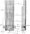
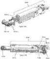
- FIGS. 1, 2 , and 3An exemplary embodiment of a robotic device is depicted in FIGS. 1, 2 , and 3 .
- the devicehas a main body, 100, a right arm A , and a left arm B.
- each of the left B and right A armsis comprised of 2 segments: an upper arm (or first link) 300A, 300B and a forearm (or second link) 200A, 200B, thereby resulting in each arm A, B having a shoulder joint (or first joint) 300.1A, 300.1B and an elbow joint (or second joint) 200.1A, 200.1B.
- each of the left arm B and right arm Ais capable of four degrees of freedom.
- the left shoulder joint 300.1B and right shoulder joint 300.1Ahave intersecting axes of rotation: shoulder yaw ( ⁇ 1) and shoulder pitch ( ⁇ 2).
- the elbow joints 200.1A, 200.1Bcontribute a degree of freedom - elbow yaw ( ⁇ 3) - and the end effectors do as well: end effector roll ( ⁇ 4).
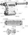
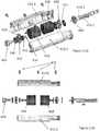
- FIGS. 4A, 4B , 4C, 4D , 4E , 4F, 4G, and 4Hdepict the device body 100 according to an exemplary embodiment. More specifically, FIG. 4A depicts a front view of the body 100, while FIG. 4B depicts a side view. In addition, FIGS. 4C, 4D, 4E , 4F, 4G, and 4H depict various perspectives of the device body 100 in which various internal components of the body 100 are visible.
- the body 100contains four motors which control shoulder yaw ( ⁇ 1) and shoulder pitch ( ⁇ 2) for the right and left arms A, B. More specifically, as best shown in FIGS. 4C , 4G , and 13D , the proximal right motor 109A and distal right motor 122A control shoulder yaw ( ⁇ 1) and shoulder pitch ( ⁇ 2) for the right shoulder 300.1A, while the proximal left motor 109B and distal left motor 122B control shoulder yaw ( ⁇ 1) and shoulder pitch ( ⁇ 2) for the left shoulder 300.1B.
- This discussionwill focus on the right shoulder 300.1A and arm A, but it is understood that a similar set of components are coupled in a similar fashion to control the yaw and pitch of the left shoulder 300.1B and left arm B.
- the proximal right motor 109Ais operably coupled to the right shoulder subassembly 127A of the right shoulder 300.1A via gear 108A, which is operably coupled to gear 115.1A on the end of the right spur shaft 115A, and the right bevel gear first right bevel gear at the opposite end of the right spur shaft 115A is operably coupled to the bevel gear 130A of the right shoulder subassembly 127A.
- distal right motor 122Ais operably coupled to the right shoulder subassembly 127A via a right distal spur gear 121A, which is operably coupled to a gear 119A, which is operably coupled to bevel gear second right bevel gear 117A, which is operably coupled to the bevel gear 130A of the right shoulder subassembly 127A.
- the proximal right motor 109A and distal right motor 122Aoperate together to control both the shoulder yaw ( ⁇ 1) and shoulder pitch ( ⁇ 2) for the right shoulder 300.1A by rotating the first right bevel gear and second right bevel gear at predetermined directions and speeds as will be described in further detail below.
- the four motors 109A, 109B, 122A, 122B, along with the motors in the arms as described elsewhere herein,are brushed direct current (DC) motors with integrated magnetic encoders and planetary gearheads.
- DCdirect current
- the motors used in the devicecan vary in size depending on the particular device embodiment and the location and/or use of the motor, with the size ranging in diameter from about 6 mm to about 10 mm.
- any known motors or other devices for converting electrical energy into rotational motioncan be used.
- the body 100has a plurality of segments that result in separate housings or subassemblies that are coupled together.
- these segments 101, 102, 103, 104, 105, and 106create housings that provide protection for internal electronics and support for internal components, including motors and drivetrain components.
- first segment 101is configured to be coupled with second segment 102 such that second segment 102 is positioned at least partially within segment first 101, thereby creating first housing 100.1 as shown in FIGS. 4A, 4B , and 5A .
- Third segment 103, fourth segment 104, and fifth segment 105are also coupled together to create second housing 100.2 as shown in FIGS. 4A, 4B , and 5A . Finally, first housing 100.1 and second housing 100.2 are coupled together as best shown in FIG. 5A .
- the segments, housings, and their assembly into the body 100are discussed in further detail below.
- the distal end (or bottom) of the body 100can also have a camera 99.
- the camera 99is a single fixed camera 99 positioned in direct line of sight of the surgical workspace.
- the body 100could have multiple cameras operating together to provide stereoscopic (3D) vision.
- any known camera or set of cameras for use in medical devicescould be used.
- the body 100can also have a lighting system such as LEDs and/or fiber optic lights to illuminate the body cavity and/or the surgical workspace.
- the plurality of segments 101, 102, 103, 104, 105, 106are made of a combination of machined aluminum and rapid prototyped plastic.
- Rapid Prototyping Primerby William Palm, May 1998 (revised July 30, 2002) (http://www.me.psu.edu/lamancusalrapidpro/primer/chapter2.htm ).
- many other known materials for medical devicescan be used, including, but not limited to, stainless steel and/or injection molded plastics.
- FIGS. 5A and 5Bdepict the first and second housings 100.1, 100.2.
- FIG. 5Adepicts the front of the first and second housings 100.1, 100.2, while FIG. 5B depicts the back.
- the proximal right motor 109A and proximal left motor 109Bare positioned in the first housing 100.1, while the distal right motor 122A and distal left motor 122B are positioned in the second housing 100.2.
- the first and second housings 100.1, 100.2are coupled together using a plurality of threaded members 107A, 107B, 107C as shown. Alternatively, any coupling mechanism can be used to retain the first 100.1 and second housings 100.2 together.
- FIGS. 6A, 6B, and 6Cdepict the second segment 102 and the positioning of the right 109A and left proximal motors 109B within.
- each of the proximal motors 109A, 109Bhas a diameter of 10 mm and is made up of three components: the right planetary gearhead 109A.1 and left planetary gearhead 109B.1, the proximal right motor drive component 109A.2, proximal left motor drive component 109B.2, and the right 109A.3 and left encoders 109B.3.
- the right 109A.1 and left 109B.1 planetary gearheadsreduce the speed of the proximal motor drive components, 109A.2, 109B.2 and thus increases the output torque. It is further understood that the right 109A.3 and left 109B.3 encoders control the position of the right proximal motor output shaft 108.1A and left proximal motor output shaft 108.1B using electric pulses which can be generated by magnetic, optic, or resistance means. Thus, the right and left encoders 109A.3, 109B.3 provide accurate positioning of the right proximal motor output shaft 108.1A and left proximal motor output shaft 108.1B.
- each of the proximal right 108A, and proximal left spur gears 108Bis used to transmit the rotational motion from the corresponding proximal motor 109A, 109B which further comprises a proximal motor drive component 109A.2, 109B.2 which acts through a planetary gearhead 109A.1, 109B.1).
- Each proximal spur gear 108A, 108Bis rotationally constrained with a "D" shaped geometric feature 108.1A, 108.1B and, in some embodiments, a bonding material such as JB-Weld.
- the second segment 102has a plurality of partial lumens, in this implementation a right partial lumen 102A and left partial lumen 102B defined within the second segment 102 that have inner walls that do not extend a full 360 degrees.
- the right and left partial lumens 102A, 102Bare configured to receive the right and left proximal motors 109A, 109B.
- the right and left proximal motors 109A, 109Bcan be positioned in the right and left partial lumens 102A, 102B as shown in FIGS. 6B, and 6C .
- the second segment 102is configured to allow for the diameter of the walls of the right and left partial lumens 102A, 102B to be reduced after the right and left proximal motors 109A, 109B have been positioned therein, thereby providing frictional resistance to rotationally and translationally secure the right and left proximal motors 109A, 109B within the right and left partial lumens 102A, 102B, thereby creating first subassembly 100.1A. More specifically, the second segment 102 allows for a clamping force to be applied to the right and left proximal motors 109A, 109B by the tightening of the thread members 110. It is understood that the right and left proximal motors 109A, 109B can also be constrained or secured by any other known method or mechanism.
- FIGS. 7A and 7Bshow the attachment or coupling of the first subassembly 100.1A with the first segment 101, thereby resulting in the first housing 100.1.
- First segment 101has a first segment mating feature 101A defined within the first segment 101 that is configured to receive the first subassembly 100.1A. More specifically, in the embodiment depicted in FIG. 7A , the first segment mating feature 101A is an opening defined in the first segment 101 that mates with the first subassembly 100.1A such that the first subassembly 100.1A fits within the opening and couples with the first segment 101.
- the first subassembly 100.1Afits within the first segment mating feature 101A such that the first subassembly 100.1A and the first segment 101 are rotationally constrained with respect to each other. Further, a first threaded member 107D is used to translationally constrain the components.
- the first segment top portion 101.1 of the first segment 101is configured or shaped to receive an external clamp (such as, for example, a commercially available external clamp available from Automated Medical Products Corp. ( http://www.ironintern.com/ ).
- the clampcan be attached to the first segment top portion 101.1 to easily and securely attach the clamp to the body 100.
- the first housing 100.1can have additional features, according to one embodiment. More specifically, the first segment 101 can have a notch or opening 101.2 defined at a bottom back portion of the first segment 101 that provides an exit site for cabling/wiring 101.4 coupled to at least one of the right and left proximal motors 109A, 109B disposed within the first housing 100.1. According to one embodiment, the opening 101.2 can provide strain relief for the cabling/wiring 101.4 to maintain the integrity of the electrical/electronic connections.
- the opening 101.2can provide a clamping feature that clamps or otherwise secures all of the cabling/wiring 101.4 that extend through the opening, such that any external forces applied to the cabling/wiring 101.4 do not extend past the opening 101.2, thereby preventing undesirable forces or strain on the connections of any of those cables/wires 101.4 to any internal components inside the first housing 100.1.
- the clamping featureresults from the coupling of first 100.1 and second housings 100.2 as best shown in FIG. 5B .
- the opening 101.2can also be filled prior to use with silicon or some other means of sealing against liquid contaminants, body fluids, etc., which can also provide additional strain relief similar to the clamping feature described above.
- first housing 100.1can also have a cavity 101.3 defined within the first housing 100.1 that allows sufficient clearance for the cabling/wiring 101.4 to extend from at least one of the right and left proximal motors 109A, 109B and exit through opening 101.2.
- FIGS. 9A, 9B, and 9Cdepict the fourth segment 104, which is a component of the second housing 100.2 discussed above and depicted in FIGS. 5A and 5B .
- the fourth segment 104has right 115.1A, and left fourth segment lumens 115.1B defined in the fourth segment 104 that are configured to receive the right proximal spur shaft 115A and left proximal spur shaft 115B, both of which are part of the drive trains that operably couple the right and left proximal motors 109A, 109B to the right and left shoulder subassemblies 127A, 127B that constitute the right 300.1A and left 300.1B shoulders of the device.
- the fourth segment 104also has right and left holes 122.1A, 122.1B defined in the fourth segment 104. These holes 122.1A, 122.1B are discussed in further detail in relation to FIGS. 11A and 11B below. While the drive train that includes the right proximal spur shaft 115A will be discussed in detail in this paragraph, it is understood that the drive train that includes the left proximal spur shaft 115B has the same components that are coupled and function in the same manner. As discussed above with respect to FIGS. 4C and 4G , the right proximal spur shaft 115A is configured to be disposed through the right lumen 115.1A of the fourth segment 104.
- first right driven gear 115.2Aat one end and is coupled to a first right bevel gear 112A at the other.
- a first right ball bearing 111Ais positioned within an opening or recess in the first right bevel gear 112A and is contacted only on its outer race by the inner wall of the opening in the first right bevel gear 112A. In the finished assembly, this contact will provide appropriate preload to this bearing.
- bearing preloadis a term and concept that is well known in the art as a mechanism or method by which to improve manufacturing tolerances from the ball bearing by applying a constant axial stress.
- first right bevel gear 112Ais coupled to the spur shaft 115A via a threaded coupling (not shown). That is, the first right bevel gear 112A has a bevel gear lumen 112.1A as best shown in FIG.
- a thread lockeris used to permanently affix the first right bevel gear 112A to the right proximal spur shaft 115A.
- the thread lockercan be Loctite, which is commercially available from Henkel Corp. in Dusseldorf, Germany.
- the second and third ball bearings 113.1A, 113.2Acontact the inner walls of the lumen 115.1A on their outer races and contact the outer surfaces of the first right bevel gear 112A and the right proximal spur shaft 115Awith their inner races.
- the act of coupling the internal threads in the bevel gear lumen 112.1A with the external threads on the outer surface of the spur shaft 115Apreloads the second and third ball bearings 113.1A, 113.2A.
- FIGS. 10A and 10Bdepict the fifth 105 and sixth 106 segments, both of which are also components of the second housing 100.2 discussed above and depicted in FIGS. 5A and 5B . It should be noted that FIGS. 10A and 10B depict the back side of these segments, while the other figures discussed herein relating to the other segments generally depict the front side.
- the sixth segment 106is an end cap segment that couples to the fifth segment 105.
- the fifth segment, 105like the fourth 104, has right and left lumens 119.1A, 119.1B defined in the fifth segment 105 that are configured to receive the right 119.3A and left distal spur shafts 119.3B, both of which are part of the drive trains that operably couple the right 122A and left 122B distal motors to the right 127A and left 127B shoulder subassemblies that constitute the right 300.1A and left 300.1B shoulders of the device.
- the segment 105also has right and left fifth segment lumens 122.4A, 122.4B configured to receive the right 122A and left 122B distal motors as best shown in FIGS. 12A and 12B and discussed below.
- the first left distal spur shaft 119.3Bis configured to be disposed through the left fifth segment lumen 119.1B. It has a left distal driven gear 119.2B at one end and is coupled to a left distal bevel gear 117B at the other.
- a fourth ball bearing 116Bis positioned within an opening or recess in the left distal bevel gear 117B and is contacted only on its outer race by the inner wall of the opening in the left distal bevel gear 117B.
- the fifth ball bearing 118.1Bis positioned over/on the bore of left distal bevel gear 117B and within the left fifth segment lumen 119.1B, while the fifth ball bearing 118.2B is positioned on/over spur the left distal gear shaft 119B and within the left fifth segment lumen 119.1B at the opposite end of the fifth segment lumen 119.1B from fifth ball bearing 118.1B.
- the left distal bevel gear 117Bis coupled to the first left distal spur shaft 119.3B via a threaded coupling (not shown). That is, the left distal bevel gear 117B has a left distal bevel gear lumen 117.1B as best shown in FIG.
- a thread lockeris used to permanently affix the left distal bevel gear 117B to the first left distal spur shaft 119.3B.
- the thread lockercan be Loctite, as described above.
- the act of coupling the internal threads in the left distal bevel gear lumen 117.1B with the external threads on the outer surface of the first left distal spur shaft 119.3Bpreloads the fifth and sixth ball bearings 118.1B, 118.2B.
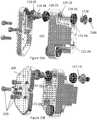
- FIGS. 11A and 11Bdepict the fourth segment 104 and, more specifically, the positioning of the right distal motor 122A and left distal motor 122B in the fourth segment holes 122.1A, 122.1B.
- the right distal motor 122A and left distal motor 122Bare 10 mm motors that are similar or identical to the right and left proximal motors 109A, 109B discussed above. Alternatively, any known motors can be used.
- Each of the right distal motor 122A and left distal motor 122Bhave a second right distal spur gear 121A and second left distal spur gear 121B, respectively.
- each second distal spur gear 121A, 121Bis coupled to the distal motor 122A, 122B with "D" geometry as described above and, in some embodiments, adhesive such as JB-Weld.
- adhesivesuch as JB-Weld.
- the right distal motor 122A and left distal motor 122Bare positioned in the right and left fourth segment holes 122.1A, 122.1B.
- the right distal motor 122A and left distal motor 122Bare positioned correctly when the right and left distal motor ends 122.2A, 122.2B contact or are substantially adjacent to the right and left distal stop tabs 122.3A, 122.3B.
- the threaded members 123are inserted in the right and left threaded member holes 123.1A, 123.1B and tightened, thereby urging the fourth segment crossbar 123.2 downward and thereby constraining the right distal motor 122A and left distal motor 122B rotationally and translationally within the fourth segment holes 122.1A, 122.1B.
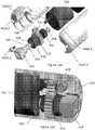
- FIGS. 12A and 12Bdepict the fourth, fifth and sixth segments 104, 105, 106 of the second housing 100.2 and how they are coupled together to form the second housing 100.2.
- the fourth, fifth and sixth segments 104, 105, 106couple together into a second housing 100.2 that forms the right 300.1A and left shoulders 300.1B of the device.
- the right distal motor 122A and left distal motor 122Bare positioned through the fifth segment lumens 122.4A, 122.4B such that the second distal spur gears 121A, 121B that are coupled to the right distal motor 122A and left distal motor 122B are positioned against the fifth segment 105 and between the fifth 105 and sixth segments 106.
- the second distal spur gears 121A, 121Btransmit the rotational motion from the right distal motor 122A and left distal motor 122B, respectively to the distal spur shafts 119.3A, 119.3B, which are positioned such that they are coupled to the second distal spur gears 121A, 121B.
- the first distal spur shafts 119.3A, 119.3Bare coupled to the second right bevel gear, 117B so that the motion is also transferred through the second right bevel gear, 117B.
- a fifth segment projection 105A on the back of the fifth segment 105is positioned in and mates with a fourth segment notch 104A in the back of the fourth segment 104, as best shown in FIG. 12B . Further threaded members are then threaded through holes in the fourth segment (not shown) and into the projection 105A, thereby further securing the fourth and fifth segments 104,105.
- This mated coupling of the fifth segment projection 105A and fourth segment notch 104Acan, in one implementation, secure the fourth and fifth segments 104, 105 to each other such that neither component is rotational in relation to the other, while the threaded members secure the segments translationally.
- the third segment 103can serve as a protective cover that can be coupled or mated with the front portion of the fourth segment 104 and retained with a threaded member 126.
- the third segment 103can help to protect the motors and electronics in the second housing 100.2.
- a gearcap cover segment 106can be coupled or mated with the bottom portion of the fourth segment 104 and retained with threaded members 120. The cover segment 106 can help to cover and protects the various gears 119A, 119B, 121A, 121B contained within the fourth segment 104.
- the coupling of the fourth 104 and fifth 105 segmentsalso results in the positioning of the second right bevel gear 117A in relation to the first right bevel gear, 112B such that the second right bevel gear 117A and the first right bevel gear 112A are positioned to couple with the right shoulder subassembly 127A to form the right shoulder 300.1A and the corresponding left bevel gears 117B, 112B are positioned to couple with the subassembly left shoulder subassembly 127B to form the left shoulder 300.1B.
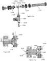
- FIGS. 13A-14CThis is depicted and explained in further detail in FIGS. 13A-14C .
- FIGS. 13A-13D and 14A-14Cdepict the shoulder subassembly design, according to one embodiment.
- the components in these figuresare numbered and will be described without reference to whether they are components of the right shoulder (designated with an "A" at the end of the number) or the left shoulder (designated with a "B" at the end of the number). Instead, it is understood that these components are substantially similar on both sides of the device and will be described as such.
- the right output shaft 128Ais positioned in the lumen 130A and also has two projections (a first 128A.1, and second 128A.2) that are configured to be positioned in the lumens of the first and second right bevel gears 112A, 117A.
- a plurality of ball bearings 111, 116are positioned over the projections 128A.1, 128A.2 such that the inner race of the bearings 111, 116 contact the projections 128A.1, 128A.2.
- a further ball bearing 129Ais positioned on/over the right output shaft 128A such that the ball bearing 129 is positioned within the lumen 130A of the right output bevel gear 130A.
- a further ball bearing 131is positioned in the opposing side of the right output bevel gear lumen 130A and on/over a threaded member 132.
- the threaded member 132is configured to be threaded into the end of the right output shaft 128A after the shaft 128A has been positioned through the lumen 130A of the right output bevel gear 130A, thereby helping to retain the right output bevel gear 130A in position over the right output shaft 128A and coupled with the first and second right bevels gears 112A, 117A.
- the full right shoulder subassembly 127Ais fully secured such that the right output bevel gear 130A is securely coupled to the first and second right bevel gears 112A, 117A.
- rotation of the first and second right bevel gears 112A, 117Arotates the right output bevel gear 130, which can cause rotation of the right shoulder subassembly 127A along at least one of two axes-axis A1 or axis A2-depending on the specific rotation and speed of each of the first and second right bevel gears 112A, 117A.
- first and second right bevel gears 112A, 117Aare rotated in the same direction at the same speed, the first and second right bevel gears 112A, 117A are essentially operating as if first and second right bevel gears 112A, 117A are a fixed, single unit that cause rotation of the shoulder subassembly 127A around axis A1.
- the right output bevel gear 130Ais rotated around axis A2. It is understood that the first and second right bevel gears 112A, 117A can also work together to achieve any combination of rotation along both axes A1, A2.
- first and second right bevel gears 112A, 117Aare driven independently by the distal and proximal motors 122A, 109A, any combination of ⁇ 1 and ⁇ 2 are achievable around axes A1 and A2.
- both gears 112A, 117Aare rotated in the same direction but at different speeds, this will result in a combined rotation of the subassembly around both the A1 axis and the A2 axis, as would be clear to one of skill in the art
- FIGS. 15A and 15Bdepict a right upper arm (or first link) 300A that is coupled to the device body 100 at right shoulder 300.1A (as also shown in FIGS. 1 and 2 ). While the following figures and discussion focus on the right upper arm 300A, it is understood that the left upper arm 300B can have the same or similar components and thus that the discussion is relevant for the left upper arm 300B as well. As shown in FIGS. 15A and 15B , the upper arm 300A is coupled to the output bevel gear 130A with two threaded screws 301A.1.
- the upper arm 300Ahas a notch 301A.1 defined in the proximal end of the arm 300A into which the output bevel gear 130A is positioned, thereby providing additional mating geometry that further secures the upper arm 300A and the output bevel gear 130A.
- the upper arm 300Ahas an upper arm motor 317A that actuates the movement of the forearm 200A at the elbow joint 200.1A of the arm A. That is, the motor 317 is coupled to an upper arm spur gear 318A, which is coupled to an upper arm driven gear 302A.
- the driven gear 302Ais coupled to a first right upper arm bevel gear 306A, which is coupled to a second right upper arm bevel gear 313A.
- the second right upper arm bevel gear 313Ais coupled to an upper arm output upper arm shaft 312AA, which is coupled to the right forearm 200A.
- FIGS. 16A and 16Bdepict the right upper arm motor 317A and the drive train coupled to the motor 317A in the upper arm 300A.
- the motor 317Ais an 8mm motor that is positioned in the upper arm 300A.
- the upper arm spur gear 318Ais coupled to the upper arm motor output shaft 317A and rotationally secured via a "D" geometry 317.1A. According to one embodiment, the upper arm spur gear 318A is further secured with JB-Weld.
- the upper arm 300Aalso has a housing 304A positioned in the arm 300A that is configured to house or support the drive train that is coupled to the upper arm motor 317A.
- the housing 304has a hole 304.3A defined by two arms 304.1A, 304.2A that is configured to receive the motor 317A.
- a screw 319Acan be positioned through holes in both arms 304.1A, 304.2A and tightened, thereby urging the arms 304.1A, 304.2A together and securing the upper arm motor 317A both rotationally and translationally within the hole 304.3A.
- an adhesivesuch as epoxy can be added help to further restrict unwanted movement of the upper arm motor 317A in relation to the upper arm housing 304A. This securing of the motor 317A in the upper arm housing 304A ensures proper coupling of upper arm spur gear 318A with the upper arm spur shaft gear 302A.
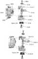
- FIGS. 17A and 17Bdepict the first 320A and second 232A segments (or “shells") that couple together to create the housing around the upper arm motor 317A.
- the first shell 320Ais positioned above the upper arm motor 317A and the second shell 323A is positioned beneath the motor 317A.
- the two shells 320A, 323Aare coupled together with screws 322A that are positioned through the second shell 323A and into the first shell 320A.
- the two shells 320A, 323Aare also coupled to the upper arm housing 304A, with the first shell 320A being coupled to the upper arm housing 304A with screws 321A and the second shell 323A being coupled to the upper arm housing 304A with further screws 324A.
- FIGS. 18A and 18Bdepict the right upper arm housing 304A and further depict the right upper arm spur shaft 302A.1 positioned in the housing 304A.
- the right upper arm spur shaft 302Ahas a right upper arm spur gear 302A.2 at one end of the spur shaft 302A.1 as best shown in FIG. 18A .
- the spur shaft 302A.1is positioned in an upper arm housing lumen 304A.1 defined in the housing 304A.
- There are two ball bearings 303, 305positioned on/over the spur shaft 302A.1 and further positioned at the openings of the upper arm housing lumen 304A.1.
- a first upper arm bearing 303is positioned on/over the spur shaft 302A.1 so that only its inner race is contacting the shaft 302A.1.
- a second upper arm bearing 305Ais positioned on/over spur shaft 302A.1 in the same manner.
- the first right upper arm bevel gear 306Ais coupled to the upper arm spur shaft 302A.1 at the end opposite the spur shaft gear 302A.2.
- the upper arm bevel gear 306Ais secured to the spur shaft 302A.1 with "D" geometry 302A.3.
- the first right upper arm bevel gear 306Acan also be further secured using adhesive such as JB-Weld.
- a screw 307Ais positioned through the first right upper arm bevel gear 306A and into the spur shaft 302A.1 such that when the screw 307A is fully threaded into the spur shaft 302A.1, the screw 307A translationally secures first right upper arm bevel gear 306A and also preloads the first 303 and second 305 upper arm bearings.
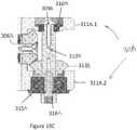
- FIGS. 19A, 19B , and 19Cdepict the upper arm shaft housing 311A coupled to the upper arm housing 304.
- the upper arm shaft housing 311Ais made up of an upper shaft housing arm 311A.1 and a lower shaft housing arm 311A.2, both of which are coupled to the upper arm housing 304A.
- the upper shaft housing arm 311A.1is coupled to the housing 304A via a first pair of screws 307A.1, while the lower shaft housing arm 311A.2 is coupled via a second pair of screws 308A.1.
- each of the shaft housing arms 311A.1, 311A.2has a hole 311A.1A, 311A.2A.
- the upper arm shaft 312AAas best shown in FIGS. 20A-20C , has a vertical shaft component 312A.1 and an appendage 312A.2 coupled to the vertical shaft component 312A.1.
- the upper arm shaft 312AAis oriented in the assembled shaft housing 311A such that an upper portion of the vertical shaft component 312A.1 is positioned in the hole 311A.1A and a lower portion of the vertical shaft component 312A.1 is positioned in the hole 311A.2A.
- a vertical shaft bevel gear 313Ais positioned over the vertical shaft component 312A.1 and above the lower shaft housing arm 311A.2 such that the vertical shaft bevel gear 313A is coupled to the first right upper arm bevel gear 306A when all components are properly positioned as best shown in FIG. 19C .
- the vertical shaft bevel gear 313Ais coupled to the vertical shaft component 312A.1 rotationally by a "D" geometry 312A.4 as best shown in FIG. 20B .
- the vertical shaft bevel gear 313Acan be further secured using JB-Weld.
- the vertical shaft component 312A.1also has two ball bearings: a first vertical shaft ball bearing 315A is positioned over the vertical shaft component 312A.1 and through hole 311A.2A so that it is in contact with the vertical shaft bevel gear 313A, while the second vertical shaft ball bearing 310A is positioned in the hole 311A.1A.
- a screw 316is positioned through the first ball bearing 315A and hole 311A.2A and threaded into the bottom of the vertical shaft component 312A.1, thereby helping to secure the upper arm shaft 312AA in the assemble shaft housing 311A and the first ball bearing 315A in the hole 311A.2A.
- a second screw 309Ais threaded into the top of the vertical shaft component 312A to secure and preload the second ball bearing 310.
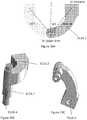
- FIGS. 20A, 20B, and 20Cdepict upper arm shaft 312A, according to one embodiment.
- the upper arm shaft 312Ahas an appendage 312A.2 that is configured to be coupled to the forearm 300A.
- the upper arm shaft 312Ais rotatable in relation to the upper arm 300A as a result of the plurality of vertical shaft ball bearings, 310A and 315A, as best depicted and described above in relation to FIGS. 19A-C .
- the upper arm shaft 312Ais rotatable by the right upper arm motor 317AA in the upper arm 300A as described above via the drive train that couples the right upper arm motor 317A to the vertical shaft bevel gear 313A, which in turn is coupled to the upper arm shaft 312A.
- the appendage 312A.2can be rotated around vertical upper arm shaft 312AA with a rotational radius or angle of ⁇ 3 as shown in FIG. 20A . In one specific implementation, the angle is 50 degrees.
- the appendage 312A.2is configured to be coupleable to a forearm 300A via the configuration or geometry of the appendage 312A.2 and the hole 312A.5 formed underneath the appendage 312A.2.
- any known forearm componentcan be coupled to either upper arm 300A, 300B.
- the forearm coupled to the upper arm 300A, 300Bis the exemplary right forearm 410, which could apply equally to a right 410A or left 410B forearm, depicted in FIGS. 21A-21D .
- the forearmhas a cylindrical body or housing 412 and an end effector 414.
- the housing 412is made up of two separate forearm housing components 412.1, 412.2 that are coupled together with three bolts (or threaded members) 472.
- the three bolts 472pass through housing component 412.1 and into threaded holes in the housing component 412.2.
- the two forearm housing components 412.1, 412.2can be coupled together by any known coupling mechanism or method.
- the end effector 414is a grasper, but it is understood that any known end effector can be coupled to and used with this forearm 410.
- the depicted embodimentcan also have a circular valley 474 defined in the distal end of the forearm housing 412. This valley 474 can be used to retain an elastic band or other similar attachment mechanism for use in attaching a protective plastic bag or other protective container intended to be positioned around the forearm 410 and/or the entire device arm and/or the entire device to maintain a cleaner robot.
- the forearm 410has two motors - a rotation motor 416 and an end effector motor 418.
- the rotation motor 416is coupled via a forearm rotation motor gear 420 and a forearm rotation motor attachment gear 422 to the forearm attachment component 424, which is configured to be coupleable to an elbow joint, such as either elbow joint 200.1A, 200.1B.
- the forearm rotation motor attachment gear 422transmits the rotational drive of the motor from the forearm rotation motor gear 420 to the forearm rotation motor attachment component 424.
- the attachment component 424as best shown in FIGS.
- the shaft 426has a D-shaped configuration 436 that mates with the D configuration of the hole 438 defined in the gear 422, thereby rotationally coupling the shaft 426 and gear 422.
- any configuration that can rotationally couple the two componentscan be incorporated.
- the bearing 430is positioned on the shaft 426 between the attachment component 424 and the attachment gear 422, while the bearing 432 is positioned between the attachment gear 422 and the motor 416.
- the bearing 430is a ball bearing.
- these bearings or bushingscan be any roller bearings or bushings that can be used to support and couple any rotatable component to a non-rotatable component or housing.
- the bearings 430, 432, attachment gear 422, and attachment component 424are secured to each other via a bolt or other type of threaded member 434 that is threaded into the threaded lumen 428 of the shaft 426.
- the two housing components 212A, 212Bhave structures defined on their interior walls that are configured to mate with the various components contained within the housing 212, including the gears 420, 422 and bearings 430, 432.
- the bearings 430, 432are configured to be positioned within the appropriate mating features in the housing components 212A, 212B. These features secure the bearings 430, 432 in their intended positions in the housing 212 when the two housing components 212A, 212B are coupled.
- the rotation motor 416is secured in its position within the housing 412 through a combination of the coupling or mating of the motor 416 with the features defined on the interior walls of the housing components 212A, 212B and two bolts or other type of threaded members 440A, 440B (one bolt - 440A - is depicted) that are threaded through the holes 442A, 442B and into holes 444A, 444B defined in the motor 416.
- the attachment component 424is an attachment nut 424.
- the specific geometry or configuration of the attachment component 424can vary depending on the specific robotic device and the specific elbow joint configuration.
- the actuation of the rotation motor 416actuates rotation of the attachment component 424, which results in rotation of the forearm 410, thereby rotating the end effector 414.
- the rotation of the end effector 414is accomplished by rotating the entire forearm 410, rather than just the end effector 414.
- the forearm 410rotates around the same axis as the axis of the end effector 414, such that rotation of the forearm 410 results in the end effector 414 rotating around its axis.
- the two axescan be offset.
- any known end effectorcan be coupled to the forearm 410.
- the end effectoris a grasper 414 having a yoke 414.2 that is positioned around the proximal ends of the grasper components 414.1.
- the grasper 414has a configuration and method of operation substantially similar to the grasper disclosed in U.S. Application 13/493,725 , published as US 2013/0041360 A1, filed on June 11, 2012 .
- any known grasper configurationcan be used.
- the end effector motor 418is configured to actuate the grasper 414 arms to open and close via the motor gear 450, which is coupled to the coupling gear 452, which is coupled to center drive rod 454, which is coupled to the grasper components 414.1.
- the grasper yoke 414.2is substantially fixed to the housing 412 so that it does not move relative to the housing 412. More specifically, the grasper yoke 414.2 is fixedly coupled to the yoke gear 460, which is positioned in the housing 412 such that it is mated with the ridged notch 462 defined in the inner wall of the housing 412, as best shown in FIG. 23B .
- the teeth of the yoke gear 460mate with the ridges of the ridge notch 462 to thereby couple the gear 460 and the housing 412.
- gluecan be placed between the yoke gear 460 and the housing as well, to further enhance the fixation of the grasper yoke 414.2 to the housing 412.
- the coupler gear 452has a center hole (not shown) that is internally threaded (not shown) such that the proximal end of the center drive rod 454 is positioned in the center hole. Because the center drive rod 454 has external threads (not shown) that mate with the internal threads of the center hole defined in the coupler gear 452, the rotation of the coupler gear 452 causes the internal threads of the center hole to engage the external threads of the drive rod 454 such that the drive rod 454 is moved translationally. This translational movement of the drive rod 454 actuates the grasper arms to move between the closed and open positions.
- the coupler gear 452is supported by two bearings 464, 466, which are secured within the housing 412 by appropriate features defined in the inner walls of the housing 412. In addition, the end effector motor 418 is secured in a fashion similar to the motor 416.
- the grasper or other end effectorcan be actuated by any known configuration of actuation and/or drive train components.
- the forearm 410when the forearm 410 and the end effector 414 are assembled, the forearm 410 can have a gap 470 between the two motors 416, 418.
- the gap 470can be a wiring gap 470 configured to provide space for the necessary wires and/or cables and any other connection components needed or desired to be positioned in the forearm 410.
- any end effectorcan be used with the robotic device embodiments disclosed and contemplated herein.
- the grasper 500has two jaws (also referred to as arms) 502.1, 502.2 that both pivot around a single pivot point 504.
- the grasper 500is a "combination" or “hybrid” grasper 500 having structures configured to perform at least two tasks, thereby reducing the need to use one tool for one task and then replace it with another tool for another task.
- each jaw 502.1, 502.2has two sizes of ridges or toothlike formations (“teeth”): larger teeth 506.1, 506.2 and smaller teeth 508.1, 508.2.
- the teethcan be any known size for use in grasper jaws, so long as one set (the larger set) is larger than the other set (the smaller set).
- the larger teeth 506.1, 506.2are intended for gross manipulations (dealing with larger amounts of tissue or larger bodies in the patient) while the smaller teeth 508.1, 508.2 are intended for finer work (such as manipulating thin tissue).
- fine workwhen fine work is to be performed, only the distal ends or tips of the jaws 502.1, 502.2 are used such that only the smaller teeth 508.1, 508.2 are used.
- the portion of the jaws 502, 502.2 having the smaller teeth 508.1, 508.2is narrower in comparison to the portion having the larger teeth 506.1, 506.2, thereby providing a thinner point that can provide more precise control of the grasper 500.
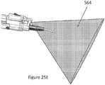
- a robotic devicecan also have at least one forearm 550 with a camera 552 as shown in FIGS. 25A-25E .
- one embodiment of the forearm 550 with a camera 552has a lumen 560A defined through a camera housing 556 positioned at the distal end of the forearm 550.
- the forearm 550also has an end cap 554 that defines a portion of the lumen 560B as well, as best shown in FIG. 25C .
- the lumens 560A, 560Bare coupled to produce a single lumen 560.
- the end cap 554is coupled to the distal end of the forearm 550 by sliding the cap 554 over the end effector 562 (which, in this particular embodiment, is a cautery component 562) and secured to the distal end of the forearm 550 using at least one screw 558.
- the camera 552can be positioned within the lumen 560 as best shown in FIGS. 25A and 25D .
- the camera 552provides a secondary viewpoint of the surgical site (in addition to the main camera on the robotic device (such as, for example, the camera 99 described above) and could potentially prevent trauma by showing a close-up view of the site.
- the camera 552is positioned such that the field of view contains the tip of the cautery (or any other end effector) 562 and as much of the surgical site as possible.
- One embodiment of the field of view 564 provided by the camera 552is depicted in FIG. 25E , in which the field of view cone is 60 degrees.
- the field of viewcan be any known size for a camera that can be incorporated into a medical device.
- multiple camerascould be incorporated into the distal end of the forearm 550.
- multiple camerascould be configured to provide stereoscopic ("3D") visualization.
- the distal end of the forearm 550could also have lights such as, for example, LED or fiber optic lights for illumination. While this particular embodiment depicts the camera 552 being used on a cautery forearm 550, the camera 552 or any similar variation of the camera 552 as contemplated herein can be incorporated into any robotic end effector in which an alternate view would be beneficial.
- the camera unitcould be positioned in a location on a robotic device other than the forearm.
- the one or more additional viewpoints provided by one or more additional camerascan be shown as a Picture In Picture (PIP) on the surgical user interface or on separate monitors.
- PIPPicture In Picture
- the various embodiments of the robotic device disclosed and contemplated hereincan be positioned in or inserted into a cavity of a patient.
- the insertion methodis the method depicted in FIGS. 26A-26F .
- the entire device 602can be inserted into the cavity as a single device, in contrast to those prior art devices that must be inserted in some unassembled state and then assembled after insertion. That is, many known surgical robotic devices prior to the embodiments disclosed herein require a relatively extensive process for insertion into the abdominal cavity. For such prior art devices, each arm must be inserted individually, aligned with a central connecting rod that is also inserted, and then coupled to the connecting rod to secure the arms in place.
- FIGS. 26A-26Fdepict the various positions of the device arms 604 during the insertion procedure, according to one embodiment.
- FIG. 26Adepicts the base or homing position required by the control kinematics. That is, as is understood by those of ordinary skill in the art, robotic devices typically have encoders that track the current position of the moving parts of the device (such as, for example, the arms 604 on this device), but the encoders track the relative position, not the actual position.
- FIG. 26Bdepicts the arms 604 in a transition position in which the arms 604 are moving from the homing position toward the fully extended vertical position of FIG. 26C .
- the shouldersare then re-positioned to the configuration shown in FIG. 26D (and in further detail in FIG. 27A in which the insertion tube 600 is depicted) in which the arms 604 are rotated to a position in which they are no longer positioned along the same vertical axis (X1) as the device body 602, but instead are positioned such that the axis (X2) of the arms 604 is parallel to and behind the device body 602.
- the rotation of the arms 604 to the position of 26D (and 27A)also results in the cross-sectional profile of the device 602 along its width being reduced by the size of the arms 604. That is, while the arms 604 in 26C are positioned alongside the device body 602 such that the width of the body 602 is enlarged by the width of the arms 604 on each side of the body 602, the rotation of the arms 604 to a position behind the body 602 also results in the arms 604 being positioned such that they are positioned within the width of the body 602 (that is, they do not extend beyond the width of the body 602). It is the configuration of the shoulders as described above that allows for this particular repositioning. The end result is a device configuration in 26D that has a smaller width than the configuration in 26C, thereby reducing the profile of the device along its width and allowing for insertion of the device without having to remove the arms.
- the devicecan begin to be inserted into the cavity. Due to the length of the arms, the device cannot be fully inserted into the cavity in this vertical position, so once the forearms are positioned inside the cavity, they are rotated to the position shown in FIG. 26E (and in further detail in FIG. 27B ). Once in this configuration, the rest of the robot is fully inserted and then the device is configured into a typical operating arrangement such as that shown in FIG. 26F (and in further detail in FIG. 27C ).
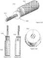
- FIGS. 27A-27Cdepict an insertion tube (also called an "overtube") 600 in which the robotic device can be stored prior to use. Further, prior to insertion, the tube 600 will be sealed to the abdominal wall after an incision has been made in the wall. Once sealed, the abdomen can be insufflated and the blue overtube and abdomen will be at equal pressures. The robot can then be inserted following the previously outlined steps discussed above.
- an insertion tubealso called an "overtube” 600 in which the robotic device can be stored prior to use.
- the tube 600will be sealed to the abdominal wall after an incision has been made in the wall. Once sealed, the abdomen can be insufflated and the blue overtube and abdomen will be at equal pressures.
- the robotcan then be inserted following the previously outlined steps discussed above.
- any of the robotic devices disclosed or contemplated abovecan also incorporate sensors to assist in determining the absolute position of the device components.
- the robotic device 650has a body 652, a right arm 654, and a left arm 656.
- the right arm 654has an upper arm 654A and a forearm 654B
- the left arm 656also has an upper arm 656A and a forearm 656B.
- each of the upper arms and forearmsare also referred to as "links.”
- the right arm 654has a shoulder joint 654C and an elbow joint 654D
- the left arm 656also has a shoulder joint 656C and an elbow joint 656D.
- various position sensors 658, 660A, 660B, 662A, 662Bare positioned on the device 650 as shown in FIG. 28 . More specifically, a first position sensor 658 is positioned on the device body 652, while a second position sensor 660A is positioned on the right upper arm 654A, a third position sensor 660B is positioned on the right forearm 654B, a fourth position sensor 662A is positioned on the left upper arm 656A, and a fifth position sensor 662B is positioned on the left forearm 656B.
- the sensorsare 3-axis sensors, as described in FIG. 29 .
- the position sensor 658 positioned on the device body 652senses the orientation of the device body 652 and then the orientation of each of the sensors 660A, 660B, 662A, 662B on the links 654A, 654B, 656A, 656B can be used to determine the current position of each link of each arm 654, 656 and the joint angles at joints 654C, 654D, 656C, 656D.
- each of the other sensors 660A, 660B, 662A, 662Bcan be used in conjunction with the sensor 658 to determine the position and orientation of both arms relative to the reference point.
- each 3-axis sensormeasures the spatial effect of the at least one environmental characteristic being measured and also determine the orientation of that sensor in all three spatial dimensions.
- Each sensor 660A, 660B, 662A, 662B on a link 654A, 654B, 656A, 656Bmeasures the environmental characteristic at that position on the link.
- the measured value and orientation of the sensor 660A, 660B, 662A, 662B on that linkcan then be used to determine the spatial orientation of each link 654A, 654B, 656A, 656B.
- the kinematic configuration of both robotic arms 654, 656can be used with the link orientations determined from the sensors to directly calculate the position of the arms 654, 656 from the known reference point: sensor 658. This known orientation can then be used to determine the position and orientation of both arms 654, 656 relative to the reference point 658.
- each linkcan be mounted on the link in any known or measureable position and orientation.
- each of the sensorscan be mounted in an interior location inside the particular component that the sensor is intended to be coupled to.
- each sensorcan be positioned on an exterior portion of the appropriate component as long as it is firmly attached to the component.
- FIG. 28depicts a robotic device 650 with two joints and two links per arm
- the position sensorscan be applied to and used with a robotic device with any number of joints and links per arm in any configuration.
- the 3-axis sensors 658, 660A, 660B, 662A, 662Bare 3-axis accelerometers that measure the acceleration due to gravity. It is understood that a 3-axis accelerometer operates in the following fashion: the acceleration due to gravity is measured and depending on the orientation of the arm link (or other device component), magnitudes of acceleration in proportion to the orientation angles of the accelerometer are sensed on the different axes 702, 704, 706 of the 3-axis accelerometer as best shown in FIG. 29 . Given the acceleration measurements on each axis of the accelerometer, the orientation of the link that the accelerometer is mounted on can be determined with respect to gravity.
- accelerometer sensorscan also measure the acceleration of the link(s) they are attached to on the robotic device.
- this acceleration datacan be integrated over time to provide a position for the links of the robot. The positions determined from this integration can be more accurate if the system model of the robot is known to help account for the effects of inertia and other internal forces.
- sensors other than accelerometerscan be used.
- Possible sensorsinclude, but are not limited to, magnetometers (measuring magnetic field from earth's magnetic field, induced magnetic field, or other magnetic field), tilt sensors, radio frequency signal strength meters, capacitance meter, or any combination or extensions of these.
- magnetometersmeasuring magnetic field from earth's magnetic field, induced magnetic field, or other magnetic field
- tilt sensorstilt sensors
- radio frequency signal strength meterscapacitance meter, or any combination or extensions of these.
- 3-axis sensorsare used in the embodiment discussed above, single or dual or other multi-axis sensors could be used.
- a gyroscopemeasures the rate of rotation in space.
- the gyroscopecan be combined with an accelerometer and magnetometer to form an inertial measurement unit, or IMU, that can be used to measure the static position of the robotic device or to calculate the position of the device while it is moving through integration of the measured data over time.
- IMUinertial measurement unit
- the sensors described abovehelp to determine or provide information about the absolute position of a device component, such as an arm.
- a device componentsuch as an arm.
- the sensor system embodiments described hereinhelp to determine the absolute position of one or more links on a robotic device.
- the position tracking systems disclosed hereinallow a robotic device or a user to autonomously determine what position the device and device arms are in at any time.
- Such a system according to the embodiments disclosed hereincan be used alone (as a primary position tracking system) or in combination with the embedded encoders (as a redundant position tracking system).
- a primary position tracking systema primary position tracking system
- the embedded encodersa redundant position tracking system
- only one position sensoris used per link
- other embodimentshave multiple sensors per link.
- the additional position sensorsprovide additional positional redundancy, and in some implementations the data collected from the multiple position sensors can be used with various filtering techniques, such as Kalman Filtering, to provide a more robust calculation of the position of the robot.
Landscapes
- Health & Medical Sciences (AREA)
- Engineering & Computer Science (AREA)
- Life Sciences & Earth Sciences (AREA)
- Surgery (AREA)
- Nuclear Medicine, Radiotherapy & Molecular Imaging (AREA)
- Medical Informatics (AREA)
- Veterinary Medicine (AREA)
- Public Health (AREA)
- Robotics (AREA)
- Biomedical Technology (AREA)
- Heart & Thoracic Surgery (AREA)
- General Health & Medical Sciences (AREA)
- Molecular Biology (AREA)
- Animal Behavior & Ethology (AREA)
- Mechanical Engineering (AREA)
- Oral & Maxillofacial Surgery (AREA)
- Pathology (AREA)
- Manipulator (AREA)
- Surgical Instruments (AREA)
Description
- The embodiments disclosed herein relate to various medical devices and related components, including robotic and/or in vivo medical devices and related components. Certain embodiments include various robotic medical devices, including robotic devices that are disposed within a body cavity and positioned using a support component disposed through an orifice or opening in the body cavity.
- Invasive surgical procedures are essential for addressing various medical conditions. When possible, minimally invasive procedures such as laparoscopy are preferred.
- However, known minimally invasive technologies such as laparoscopy are limited in scope and complexity due in part to 1) mobility restrictions resulting from using rigid tools inserted through access ports, and 2) limited visual feedback. Known robotic systems such as theda Vinci® Surgical System (available from Intuitive Surgical, Inc., located in Sunnyvale, CA) are also restricted by the access ports, as well as having the additional disadvantages of being very large, very expensive, unavailable in most hospitals, and having limited sensory and mobility capabilities.
- There is a need in the art for improved surgical systems and devices.
US2008/109014 A1 discloses a robotic surgical device for using in laparoscopic surgery, including two robotic arms.WO 2011/135503 A1 discloses a robotic arm especially suited for laparoscopic surgery.DE 10 2010 040405 A1 discloses an instrument system for a manipulator arm of an endoscopic robot.WO 01/89405 A1US 4 922 782 A discloses a two-arm type manipulator.FIG. 1 is a top perspective view of a robotic surgical system according to one embodiment.FIG. 2 is the same perspective view of the device ofFIG. 1 .FIG. 3 is the same perspective view of the device ofFIG. 1 .FIG. 4A is a schematic of a robotic medical device body from the top, according to one embodiment.FIG. 4B is a schematic of a robotic medical device body from the side, according to the embodiment ofFIG. 4A .FIG. 4C is a perspective schematic of a robotic medical device body, according to the embodiment ofFIG. 4A .FIG. 4D is an exploded perspective schematic of a robotic medical device body, according to the embodiment ofFIG. 4A .FIG. 4E is an exploded perspective schematic of a robotic medical device body, according to the embodiment ofFIG. 4A .FIG. 4E is a front view see through schematic of a robotic medical device body, according to the embodiment ofFIG. 4A .FIG. 4G is a top view see through schematic of a robotic medical device body, according to the embodiment ofFIG. 4A .FIG. 4H is a side view see through schematic of a robotic medical device body, according to the embodiment ofFIG. 4A .FIG. 5A is a top perspective separated schematic of the body of a robotic device and related equipment, according to one embodiment.FIG. 5B is a top perspective separated schematic of the body of a robotic device and related equipment, according to the embodiment ofFIG. 5A .FIG. 6A is a top perspective separated schematic of the internal components of body of a robotic device and related equipment, according to one embodiment.FIG. 6B is a top perspective separated schematic of the internal components of a robotic device and related equipment, according to the embodiment ofFIG. 6A .FIG. 6C is an endlong schematic of the internal components of a robotic device and related equipment, according to the embodiment ofFIG. 6A .FIG. 7A is a top perspective separated schematic of the internal components and body of a robotic device and related equipment, according to one embodiment.FIG. 7B is a top perspective schematic of a section of the body of a robotic device and related equipment, according to the embodiment ofFIG. 7A .FIG. 8A is a top perspective separated schematic of the internal components and body of a robotic device and related equipment, according to one embodiment.FIG. 8B is a sectional view of the body of a robotic device and related equipment, according to the embodiment ofFIG. 8A .FIG. 9A is another exploded perspective view of internal components of a robotic device, according to one embodiment.FIG. 9B is a sectional view of the body of a robotic device and related equipment, according to the embodiment ofFIG. 9A .FIG. 9C is a close exploded view of bevel gear and spur shaft of a robotic device and related equipment, according to the embodiment ofFIG. 9A .FIG. 10A is an perspective exploded view of the body segments of a robotic device and related equipment, according to another embodiment.FIG. 10B is an perspective exploded view of the body segments of a robotic device and related equipment, according to the embodiment ofFIG. 10A .FIG. 11A is an perspective exploded view of a body segment of a robotic device and related equipment, according to another embodiment.FIG. 11B is an endlong sectional view of a body segment of a robotic device and related equipment, according to the embodiment ofFIG. 11A .FIG. 12A is an perspective exploded view of the body segments of a robotic device and related equipment, according to another embodiment.FIG. 12B is an opposite perspective exploded view of the body segments of a robotic device and related equipment, according to the embodiment ofFIG. 12A .FIG. 13A is an perspective exploded view of the shoulder joint of a robotic device and related equipment, according to another embodiment.FIG. 13B is a side view of the shoulder joint of a robotic device and related equipment, according to the embodiment ofFIG. 13A .FIG. 13C is a cross sectional view of a shoulder joint of a robotic device and related equipment, according to the embodiment ofFIG. 13A .FIG. 13D is a cross sectional view of a shoulder joint of a robotic device and related equipment, according to the embodiment ofFIG. 13A .FIG. 14A is a bottom view of the shoulder joint of a robotic device and related equipment, according to another embodiment.FIG. 14B is a perspective view of the shoulder joint of a robotic device and related equipment, according to the embodiment ofFIG. 14A .FIG. 14C is a bottom view of the shoulder joints of a robotic device and related equipment, according to the embodiment ofFIG. 14A .FIG. 15A is a perspective view of the upper arm of a robotic device and related equipment, according to another embodiment.FIG. 15B is a side view of the upper arm of a robotic device and related equipment, according to the embodiment ofFIG. 15A .FIG. 16A is an exploded perspective view of the motor and drive train of a robotic device and related equipment, according to another embodiment.FIG. 16B is a side view of the motor and drive train of a robotic device and related equipment, according to the embodiment ofFIG. 16A .FIG. 17A is an exploded side view of the housing segments of a robotic device and related equipment, according to another embodiment.FIG. 17B is an exploded perspective view of the housing segments of a robotic device and related equipment, according to the embodiment ofFIG. 17A .FIG. 18A is an exploded side view of the housing and spur shaft of a robotic device and related equipment, according to another embodiment.FIG. 18B is a side cross-sectional view of the housing and spur shaft of a robotic device and related equipment, according to the embodiment ofFIG. 18A .FIG. 19A is an exploded side perspective view of the shaft housing and housing of a robotic device and related equipment, according to another embodiment.FIG. 19B is an opposite exploded side perspective view of the shaft housing and housing a robotic device and related equipment, according to the embodiment ofFIG. 19A .FIG. 19C is a cross-sectional view of the shaft housing and housing a robotic device and related equipment, according to the embodiment ofFIG. 19A .FIG. 20A is a side view of the shaft of a robotic device and related equipment, according to another embodiment.FIG. 20B is a perspective view of the shaft of a robotic device and related equipment, according to the embodiment ofFIG. 20A .FIG. 20C is another perspective view of the shaft of a robotic device and related equipment, according to the embodiment ofFIG. 20A .FIG. 21A is a perspective view of the forearm of a robotic device and related equipment, according to another embodiment.FIG. 21B is a side view of the forearm of a robotic device and related equipment, according to the embodiment ofFIG. 21A .FIG. 21C is another side view of the forearm of a robotic device and related equipment, according to the embodiment ofFIG. 21A .FIG. 21D is an end view of the forearm of a robotic device and related equipment, according to the embodiment ofFIG. 21A .FIG. 21E is a cross sectional side view of the forearm of a robotic device and related equipment, according to the embodiment ofFIG. 21A .FIG. 21F is a side view of the forearm of a robotic device and related equipment, according to the embodiment ofFIG. 21A .FIG. 21G is an exploded perspective view of the forearm and internal components of a robotic device and related equipment, according to the embodiment ofFIG. 21A .FIG. 21H is a side view of the forearm and internal components of a robotic device and related equipment, according to the embodiment ofFIG. 21A .FIG. 22A is an exploded close-up view of the proximal end of the forearm and internal components of a robotic device and related equipment, according to another embodiment.FIG. 22B is a cutaway close-up view of the proximal end of the forearm and internal components of a robotic device and related equipment, according to the embodiment ofFIG. 22A .FIG. 23A is a cutaway close-up view of the grasper end of the forearm and internal components of a robotic device and related equipment, according to another embodiment.FIG. 23B is an exploded close-up view of the grasper end of the forearm and internal components of a robotic device and related equipment, according to the embodiment ofFIG. 23A .FIG. 24 is a perspective close-up view of the grasper of a robotic device and related equipment, according to another yet implementation.FIG. 25A is a see-through side view of the forearm having a camera and internal components of a robotic device and related equipment, according to another embodiment.FIG. 25B is an exploded and see-through view of the forearm having a camera of a robotic device and related equipment, according to the embodiment ofFIG. 25A .FIG. 25C is a close up perspective view of the forearm having a camera of a robotic device and related equipment, according to the embodiment ofFIG. 25A .FIG. 25D is another close up perspective view of the forearm having a camera of a robotic device and related equipment, according to the embodiment ofFIG. 25A .FIG. 25E is a perspective view of the forearm having a camera detailing the camera's field of vision for a robotic device and related equipment, according to the embodiment ofFIG. 25A .FIG. 26A is a side view of the forearm and body of a robotic device and related equipment in one position, according to another embodiment.FIG. 26B is a side view of the forearm and body of a robotic device and related equipment in one position, according to the embodiment ofFIG. 26A .FIG. 26C is a side view of the forearm and body of a robotic device and related equipment in one position, according to the embodiment ofFIG. 26A .FIG. 26D is a side view of the forearm and body of a robotic device and related equipment in one position, according to the embodiment ofFIG. 26A .FIG. 26E is a side view of the forearm and body of a robotic device and related equipment in one position, according to the embodiment ofFIG. 26A .FIG. 26F is a side view of the forearm and body of a robotic device and related equipment in one position, according to the embodiment ofFIG. 26A .FIG. 27A is a side view of the forearm and body of a robotic device and related equipment in one position inside the body, according to another embodiment.FIG. 27B is a side view of the forearm and body of a robotic device and related equipment in one position inside the body according to the embodiment ofFIG. 27A .FIG. 27C is a perspective view of the forearm and body of a robotic device and related equipment in one position inside the body, according to the embodiment ofFIG. 27A .FIG. 28 is front view of a robotic device and related equipment in one position inside the body, according to one embodiment.FIG. 29 is a perspective view of an accelerometer according to one embodiment.- The various embodiments disclosed or contemplated herein relate to surgical robotic devices and systems. The invention is set out in the appended set of claims. More specifically, various embodiments relate to various medical devices, including robotic devices and related systems. Certain implementations relate to such devices for use in laparoendoscopic single-site (LESS) surgical procedures.
- It is understood that the various embodiments of robotic devices and related systems disclosed herein can be incorporated into or used with any other known medical devices and systems. For example, the various embodiments disclosed herein may be incorporated into or used with any of the medical devices and systems disclosed in co-pending U.S. Applications
11/766,683 US 2008/0004634 A1, filed on June 21, 2007 and entitled "Magnetically Coupleable Robotic Devices and Related Methods"),11/766,720 US 2008/0058835 A1, filed on June 21, 2007 and entitled "Magnetically Coupleable Surgical Robotic Devices and Related Methods"),11/966,741 US 2008/0221591 A1, filed on December 28, 2007 and entitled "Methods, Systems, and Devices for Surgical Visualization and Device Manipulation"),61/030,588 (filed on February 22, 2008 12/171,413 US 2009/0054909 A1, filed on July 11, 2008 and entitled "Methods and Systems of Actuation in Robotic Devices"),12/192,663 US 2009/0076536 A1, filed August 15, 2008 and entitled "Medical Inflation, Attachment, and Delivery Devices and Related Methods"),12/192,779 US 2009/0048612 A1, filed on August 15, 2008 and entitled "Modular and Cooperative Medical Devices and Related Systems and Methods"),12/324,364 US 2009/0171373 A1, filed November 26, 2008 and entitled "Multifunctional Operational Component for Robotic Devices"),61/640,879 (filed on May 1, 2012 13/493,725 US 2013/0041360 A1, filed June 11, 2012 and entitled "Methods, Systems, and Devices Relating to Surgical End Effectors"),13/546,831 US 2013/0178867 A1, filed July 11, 2012 and entitled "Robotic Surgical Devices, Systems, and Related Methods"),61/680,809 (filed August 8, 2012 13/573,849 (filed October 9, 2012 13/738,706 US 2014/0058205 A1, filed January 10, 2013 and entitled "Methods, Systems, and Devices for Surgical Access and Insertion"), andU.S. Patents 7,492,116 (filed on October 31, 2007 and entitled "Robot for Surgical Applications"),7,772,796 (filed on April 3, 2007 and entitled "Robot for Surgical Applications"), and8,179,073 (issued May 15, 2011 , and entitled "Robotic Devices with Agent Delivery Components and Related Methods"). - Certain device and system implementations disclosed in the applications listed above can be positioned within a body cavity of a patient in combination with a support component similar to those disclosed herein. An "in vivo device" as used herein means any device that can be positioned, operated, or controlled at least in part by a user while being positioned within a body cavity of a patient, including any device that is coupled to a support component such as a rod or other such component that is disposed through an opening or orifice of the body cavity, also including any device positioned substantially against or adjacent to a wall of a body cavity of a patient, further including any such device that is internally actuated (having no external source of motive force), and additionally including any device that may be used laparoscopically or endoscopically during a surgical procedure. As used herein, the terms "robot," and "robotic device" shall refer to any device that can perform a task either automatically or in response to a command.
- Certain embodiments provide for insertion of the present invention into the cavity while maintaining sufficient insufflation of the cavity. Further embodiments minimize the physical contact of the surgeon or surgical users with the present invention during the insertion process. Other implementations enhance the safety of the insertion process for the patient and the present invention. For example, some embodiments provide visualization of the present invention as it is being inserted into the patient's cavity to ensure that no damaging contact occurs between the system/device and the patient. In addition, certain embodiments allow for minimization of the incision size/length. Further implementations reduce the complexity of the access/insertion procedure and/or the steps required for the procedure. Other embodiments relate to devices that have minimal profiles, minimal size, or are generally minimal in function and appearance to enhance ease of handling and use.
- Certain implementations disclosed herein relate to "combination" or "modular" medical devices that can be assembled in a variety of configurations. For purposes of this application, both "combination device" and "modular device" shall mean any medical device having modular or interchangeable components that can be arranged in a variety of different configurations. The modular components and combination devices disclosed herein also include segmented triangular or quadrangular-shaped combination devices. These devices, which are made up of modular components (also referred to herein as "segments") that are connected to create the triangular or quadrangular configuration, can provide leverage and/or stability during use while also providing for substantial payload space within the device that can be used for larger components or more operational components. As with the various combination devices disclosed and discussed above, according to one embodiment these triangular or quadrangular devices can be positioned inside the body cavity of a patient in the same fashion as those devices discussed and disclosed above.
- An exemplary embodiment of a robotic device is depicted in
FIGS. 1, 2 , and3 . The device has a main body, 100, a right arm A , and a left arm B. As best shown inFIG. 2 , each of the left B and right A arms is comprised of 2 segments: an upper arm (or first link) 300A, 300B and a forearm (or second link) 200A, 200B, thereby resulting in each arm A, B having a shoulder joint (or first joint) 300.1A, 300.1B and an elbow joint (or second joint) 200.1A, 200.1B. As best shown inFIGS. 2-32 , in certain implementations, each of the left arm B and right arm A is capable of four degrees of freedom. The left shoulder joint 300.1B and right shoulder joint 300.1A have intersecting axes of rotation: shoulder yaw (θ1) and shoulder pitch (θ2). The elbow joints 200.1A, 200.1B contribute a degree of freedom - elbow yaw (θ3) - and the end effectors do as well: end effector roll (θ4). FIGS. 4A, 4B ,4C, 4D ,4E ,4F, 4G, and 4H depict thedevice body 100 according to an exemplary embodiment. More specifically,FIG. 4A depicts a front view of thebody 100, whileFIG. 4B depicts a side view. In addition,FIGS. 4C, 4D, 4E ,4F, 4G, and 4H depict various perspectives of thedevice body 100 in which various internal components of thebody 100 are visible.- The
body 100 contains four motors which control shoulder yaw (θ1) and shoulder pitch (θ2) for the right and left arms A, B. More specifically, as best shown inFIGS. 4C ,4G , and13D , the proximalright motor 109A and distalright motor 122A control shoulder yaw (θ1) and shoulder pitch (θ2) for the right shoulder 300.1A, while the proximalleft motor 109B and distalleft motor 122B control shoulder yaw (θ1) and shoulder pitch (θ2) for the left shoulder 300.1B. This discussion will focus on the right shoulder 300.1A and arm A, but it is understood that a similar set of components are coupled in a similar fashion to control the yaw and pitch of the left shoulder 300.1B and left arm B. - As best shown in
FIG. 4G (and as will be explained in further detail elsewhere herein), the proximalright motor 109A is operably coupled to theright shoulder subassembly 127A of the right shoulder 300.1A viagear 108A, which is operably coupled to gear 115.1A on the end of theright spur shaft 115A, and the right bevel gear first right bevel gear at the opposite end of theright spur shaft 115A is operably coupled to thebevel gear 130A of theright shoulder subassembly 127A. In addition, the distalright motor 122A is operably coupled to theright shoulder subassembly 127A via a rightdistal spur gear 121A, which is operably coupled to agear 119A, which is operably coupled to bevel gear secondright bevel gear 117A, which is operably coupled to thebevel gear 130A of theright shoulder subassembly 127A. The proximalright motor 109A and distalright motor 122A operate together to control both the shoulder yaw (θ1) and shoulder pitch (θ2) for the right shoulder 300.1A by rotating the first right bevel gear and second right bevel gear at predetermined directions and speeds as will be described in further detail below. - In one embodiment, the four
motors - As best shown in
FIGS. 4A and 4B , according to one implementation, thebody 100 has a plurality of segments that result in separate housings or subassemblies that are coupled together. In the implementation depicted inFIGS. 4A and 4B , there are six segments, but other numbers are possible. Thesesegments FIGS. 4A and 4B ,first segment 101 is configured to be coupled withsecond segment 102 such thatsecond segment 102 is positioned at least partially within segment first 101, thereby creating first housing 100.1 as shown inFIGS. 4A, 4B , and5A .Third segment 103,fourth segment 104, andfifth segment 105 are also coupled together to create second housing 100.2 as shown inFIGS. 4A, 4B , and5A . Finally, first housing 100.1 and second housing 100.2 are coupled together as best shown inFIG. 5A . The segments, housings, and their assembly into thebody 100 are discussed in further detail below. - As best shown in
FIG. 4A , in certain embodiments, the distal end (or bottom) of thebody 100 can also have acamera 99. In the implementation shown inFIG. 4A , thecamera 99 is a single fixedcamera 99 positioned in direct line of sight of the surgical workspace. Alternatively, thebody 100 could have multiple cameras operating together to provide stereoscopic (3D) vision. In a further alternative, any known camera or set of cameras for use in medical devices could be used. In further embodiments, thebody 100 can also have a lighting system such as LEDs and/or fiber optic lights to illuminate the body cavity and/or the surgical workspace. - In one implementation, the plurality of
segments FIGS. 5A and 5B depict the first and second housings 100.1, 100.2.FIG. 5A depicts the front of the first and second housings 100.1, 100.2, whileFIG. 5B depicts the back. As best shown inFIGS. 4C-4H in combination withFIGS. 5A and 5B , the proximalright motor 109A and proximalleft motor 109B are positioned in the first housing 100.1, while the distalright motor 122A and distalleft motor 122B are positioned in the second housing 100.2. The first and second housings 100.1, 100.2 are coupled together using a plurality of threadedmembers FIGS. 6A, 6B, and 6C depict thesecond segment 102 and the positioning of the right 109A and leftproximal motors 109B within. In this specific embodiment, each of theproximal motors - Thus, in certain implementations, each of the proximal right 108A, and proximal left spur gears 108B is used to transmit the rotational motion from the corresponding
proximal motor proximal spur gear - As shown in
FIGS. 6A, 6B, and 6C , thesecond segment 102 has a plurality of partial lumens, in this implementation a rightpartial lumen 102A and leftpartial lumen 102B defined within thesecond segment 102 that have inner walls that do not extend a full 360 degrees. The right and leftpartial lumens proximal motors proximal motors partial lumens FIGS. 6B, and 6C . In one embodiment, thesecond segment 102 is configured to allow for the diameter of the walls of the right and leftpartial lumens proximal motors proximal motors partial lumens second segment 102 allows for a clamping force to be applied to the right and leftproximal motors thread members 110. It is understood that the right and leftproximal motors FIGS. 7A and 7B show the attachment or coupling of the first subassembly 100.1A with thefirst segment 101, thereby resulting in the first housing 100.1.First segment 101 has a firstsegment mating feature 101A defined within thefirst segment 101 that is configured to receive the first subassembly 100.1A. More specifically, in the embodiment depicted inFIG. 7A , the firstsegment mating feature 101A is an opening defined in thefirst segment 101 that mates with the first subassembly 100.1A such that the first subassembly 100.1A fits within the opening and couples with thefirst segment 101. In one embodiment, the first subassembly 100.1A fits within the firstsegment mating feature 101A such that the first subassembly 100.1A and thefirst segment 101 are rotationally constrained with respect to each other. Further, a first threadedmember 107D is used to translationally constrain the components.- In accordance with one implementation, the first segment top portion 101.1 of the
first segment 101 is configured or shaped to receive an external clamp (such as, for example, a commercially available external clamp available from Automated Medical Products Corp. (http://www.ironintern.com/). The clamp can be attached to the first segment top portion 101.1 to easily and securely attach the clamp to thebody 100. - As shown in
FIGS. 8A and 8B , the first housing 100.1 can have additional features, according to one embodiment. More specifically, thefirst segment 101 can have a notch or opening 101.2 defined at a bottom back portion of thefirst segment 101 that provides an exit site for cabling/wiring 101.4 coupled to at least one of the right and leftproximal motors FIG. 5B . The urging of all the cabling/wiring 101.4 into the opening 101.2 for purposes of allowing for coupling of the housings 100.1 and 100.2 results in a "clamping" of the cabling/wiring 101.4 resulting from the frictional restriction of the cabling/wiring 101.4 in the opening 101.2. In some alternative embodiments, the opening 101.2 can also be filled prior to use with silicon or some other means of sealing against liquid contaminants, body fluids, etc., which can also provide additional strain relief similar to the clamping feature described above. In addition, the first housing 100.1 can also have a cavity 101.3 defined within the first housing 100.1 that allows sufficient clearance for the cabling/wiring 101.4 to extend from at least one of the right and leftproximal motors FIGS. 9A, 9B, and 9C depict thefourth segment 104, which is a component of the second housing 100.2 discussed above and depicted inFIGS. 5A and 5B . Thefourth segment 104 has right 115.1A, and left fourth segment lumens 115.1B defined in thefourth segment 104 that are configured to receive the rightproximal spur shaft 115A and leftproximal spur shaft 115B, both of which are part of the drive trains that operably couple the right and leftproximal motors left shoulder subassemblies fourth segment 104 also has right and left holes 122.1A, 122.1B defined in thefourth segment 104. These holes 122.1A, 122.1B are discussed in further detail in relation toFIGS. 11A and 11B below. While the drive train that includes the rightproximal spur shaft 115A will be discussed in detail in this paragraph, it is understood that the drive train that includes the leftproximal spur shaft 115B has the same components that are coupled and function in the same manner. As discussed above with respect toFIGS. 4C and4G , the rightproximal spur shaft 115A is configured to be disposed through the right lumen 115.1A of thefourth segment 104. It has a first right driven gear 115.2A at one end and is coupled to a firstright bevel gear 112A at the other. In addition, as best shown inFIGS. 9A and 9B , a first right ball bearing 111A is positioned within an opening or recess in the firstright bevel gear 112A and is contacted only on its outer race by the inner wall of the opening in the firstright bevel gear 112A. In the finished assembly, this contact will provide appropriate preload to this bearing. It is understood by those of ordinary skill in the art that "bearing preload" is a term and concept that is well known in the art as a mechanism or method by which to improve manufacturing tolerances from the ball bearing by applying a constant axial stress.- Further, a second right ball bearing 113.1A is positioned on or around the hub of the first
right bevel gear 112A so that its inner race is the only contact with the hub of the firstright bevel gear 112A. A third ball bearing 113.2A is positioned on or around the rightproximal spur shaft 115A in a similar manner and further is positioned in a right bore hole 113.3A in the right lumen 115.1A, as best shown inFIG. 9B . According to one embodiment, firstright bevel gear 112A is coupled to thespur shaft 115A via a threaded coupling (not shown). That is, the firstright bevel gear 112A has a bevel gear lumen 112.1A as best shown inFIG. 9C that contains internal threads (not shown) while thespur shaft 115A has external threads (not shown) defined on an outer surface at the end of theshaft 115A that comes into contact with firstright bevel gear 112A. In one implementation, a thread locker is used to permanently affix the firstright bevel gear 112A to the rightproximal spur shaft 115A. According to one particular exemplary embodiment, the thread locker can be Loctite, which is commercially available from Henkel Corp. in Dusseldorf, Germany. As such, the second and third ball bearings 113.1A, 113.2A contact the inner walls of the lumen 115.1A on their outer races and contact the outer surfaces of the firstright bevel gear 112A and the right proximal spur shaft 115Awith their inner races. Further, in one embodiment, the act of coupling the internal threads in the bevel gear lumen 112.1A with the external threads on the outer surface of thespur shaft 115A preloads the second and third ball bearings 113.1A, 113.2A. FIGS. 10A and 10B depict the fifth 105 and sixth 106 segments, both of which are also components of the second housing 100.2 discussed above and depicted inFIGS. 5A and 5B . It should be noted thatFIGS. 10A and 10B depict the back side of these segments, while the other figures discussed herein relating to the other segments generally depict the front side. In one implementation, thesixth segment 106 is an end cap segment that couples to thefifth segment 105. The fifth segment, 105, like the fourth 104, has right and left lumens 119.1A, 119.1B defined in thefifth segment 105 that are configured to receive the right 119.3A and left distal spur shafts 119.3B, both of which are part of the drive trains that operably couple the right 122A and left 122B distal motors to the right 127A and left 127B shoulder subassemblies that constitute the right 300.1A and left 300.1B shoulders of the device. In addition, thesegment 105 also has right and left fifth segment lumens 122.4A, 122.4B configured to receive the right 122A and left 122B distal motors as best shown inFIGS. 12A and 12B and discussed below.- While the drive train that includes the first left distal spur shaft 119.3B will be discussed in detail in this paragraph, it is understood that the drive train that includes the first right distal spur shaft 119.3A has the same components that are coupled and function in the same manner. The first left distal spur shaft 119.3B is configured to be disposed through the left fifth segment lumen 119.1B. It has a left distal driven gear 119.2B at one end and is coupled to a left
distal bevel gear 117B at the other. In addition, a fourth ball bearing 116B is positioned within an opening or recess in the leftdistal bevel gear 117B and is contacted only on its outer race by the inner wall of the opening in the leftdistal bevel gear 117B. Further, the fifth ball bearing 118.1B is positioned over/on the bore of leftdistal bevel gear 117B and within the left fifth segment lumen 119.1B, while the fifth ball bearing 118.2B is positioned on/over spur the left distal gear shaft 119B and within the left fifth segment lumen 119.1B at the opposite end of the fifth segment lumen 119.1B from fifth ball bearing 118.1B. According to one embodiment, the leftdistal bevel gear 117B is coupled to the first left distal spur shaft 119.3B via a threaded coupling (not shown). That is, the leftdistal bevel gear 117B has a left distal bevel gear lumen 117.1B as best shown inFIG. 10B that contains internal threads (not shown) while the first left distal spur shaft 119.3B has external threads (not shown) defined on an outer surface at the end of the first left distal spur shaft 119.3B that comes into contact with leftdistal bevel gear 117B. In one implementation, a thread locker is used to permanently affix the leftdistal bevel gear 117B to the first left distal spur shaft 119.3B. According to one particular exemplary embodiment, the thread locker can be Loctite, as described above. In one embodiment, the act of coupling the internal threads in the left distal bevel gear lumen 117.1B with the external threads on the outer surface of the first left distal spur shaft 119.3B preloads the fifth and sixth ball bearings 118.1B, 118.2B. FIGS. 11A and 11B depict thefourth segment 104 and, more specifically, the positioning of the rightdistal motor 122A and leftdistal motor 122B in the fourth segment holes 122.1A, 122.1B. The rightdistal motor 122A and leftdistal motor 122B, according to one embodiment, are 10 mm motors that are similar or identical to the right and leftproximal motors distal motor 122A and leftdistal motor 122B have a second rightdistal spur gear 121A and second leftdistal spur gear 121B, respectively. In one embodiment, each seconddistal spur gear distal motor FIGS. 11A , the rightdistal motor 122A and leftdistal motor 122B are positioned in the right and left fourth segment holes 122.1A, 122.1B. In one implementation, the rightdistal motor 122A and leftdistal motor 122B are positioned correctly when the right and left distal motor ends 122.2A, 122.2B contact or are substantially adjacent to the right and left distal stop tabs 122.3A, 122.3B. When the rightdistal motor 122A and leftdistal motor 122B are positioned as desired, the threadedmembers 123 are inserted in the right and left threaded member holes 123.1A, 123.1B and tightened, thereby urging the fourth segment crossbar 123.2 downward and thereby constraining the rightdistal motor 122A and leftdistal motor 122B rotationally and translationally within the fourth segment holes 122.1A, 122.1B.FIGS. 12A and 12B depict the fourth, fifth andsixth segments sixth segments distal motor 122A and leftdistal motor 122B are positioned through the fifth segment lumens 122.4A, 122.4B such that the seconddistal spur gears distal motor 122A and leftdistal motor 122B are positioned against thefifth segment 105 and between the fifth 105 andsixth segments 106. The seconddistal spur gears distal motor 122A and leftdistal motor 122B, respectively to the distal spur shafts 119.3A, 119.3B, which are positioned such that they are coupled to the seconddistal spur gears FIGS. 10A and 10B , the first distal spur shafts 119.3A, 119.3B are coupled to the second right bevel gear, 117B so that the motion is also transferred through the second right bevel gear, 117B.- When the fourth, fifth and
sixth segments fifth segment projection 105A on the back of thefifth segment 105 is positioned in and mates with afourth segment notch 104A in the back of thefourth segment 104, as best shown inFIG. 12B . Further threaded members are then threaded through holes in the fourth segment (not shown) and into theprojection 105A, thereby further securing the fourth and fifth segments 104,105. This mated coupling of thefifth segment projection 105A andfourth segment notch 104A can, in one implementation, secure the fourth andfifth segments - In one implementation best shown in
FIG. 12A , thethird segment 103 can serve as a protective cover that can be coupled or mated with the front portion of thefourth segment 104 and retained with a threadedmember 126. In these embodiments, thethird segment 103 can help to protect the motors and electronics in the second housing 100.2. In addition, agearcap cover segment 106 can be coupled or mated with the bottom portion of thefourth segment 104 and retained with threadedmembers 120. Thecover segment 106 can help to cover and protects thevarious gears fourth segment 104. The coupling of the fourth 104 and fifth 105 segments also results in the positioning of the secondright bevel gear 117A in relation to the first right bevel gear, 112B such that the secondright bevel gear 117A and the firstright bevel gear 112A are positioned to couple with theright shoulder subassembly 127A to form the right shoulder 300.1A and the correspondingleft bevel gears shoulder subassembly 127B to form the left shoulder 300.1B. This is depicted and explained in further detail inFIGS. 13A-14C . FIGS. 13A-13D and14A-14C depict the shoulder subassembly design, according to one embodiment. The components in these figures are numbered and will be described without reference to whether they are components of the right shoulder (designated with an "A" at the end of the number) or the left shoulder (designated with a "B" at the end of the number). Instead, it is understood that these components are substantially similar on both sides of the device and will be described as such.- The
shoulder subassemblies output bevel gears 130A, 130B (which couples with theright bevel gears bevel gears right lumen 130A and left lumen (not pictured) configured to receive theright output shaft 128A and left output shaft. Theright output shaft 128A is positioned in thelumen 130A and also has two projections (a first 128A.1, and second 128A.2) that are configured to be positioned in the lumens of the first and secondright bevel gears - A further ball bearing 129A is positioned on/over the
right output shaft 128A such that the ball bearing 129 is positioned within thelumen 130A of the rightoutput bevel gear 130A. Yet a further ball bearing 131 is positioned in the opposing side of the right outputbevel gear lumen 130A and on/over a threaded member 132. The threaded member 132 is configured to be threaded into the end of theright output shaft 128A after theshaft 128A has been positioned through thelumen 130A of the rightoutput bevel gear 130A, thereby helping to retain the rightoutput bevel gear 130A in position over theright output shaft 128A and coupled with the first and second right bevels gears 112A, 117A. Once the threaded member 132 is positioned in theright output shaft 128A and fully threaded therein, the fullright shoulder subassembly 127A is fully secured such that the rightoutput bevel gear 130A is securely coupled to the first and secondright bevel gears - In operation, as best shown in
FIG. 13B , rotation of the first and secondright bevel gears output bevel gear 130, which can cause rotation of theright shoulder subassembly 127A along at least one of two axes-axis A1 or axis A2-depending on the specific rotation and speed of each of the first and secondright bevel gears right bevel gears right bevel gears right bevel gears shoulder subassembly 127A around axis A1. In an alternative example, if the first and secondright bevel gears output bevel gear 130A is rotated around axis A2. It is understood that the first and secondright bevel gears right bevel gears proximal motors FIGS. 15A and 15B depict a right upper arm (or first link) 300A that is coupled to thedevice body 100 at right shoulder 300.1A (as also shown inFIGS. 1 and 2 ). While the following figures and discussion focus on the rightupper arm 300A, it is understood that the leftupper arm 300B can have the same or similar components and thus that the discussion is relevant for the leftupper arm 300B as well. As shown inFIGS. 15A and 15B , theupper arm 300A is coupled to theoutput bevel gear 130A with two threaded screws 301A.1. In addition, according to certain embodiments, theupper arm 300A has a notch 301A.1 defined in the proximal end of thearm 300A into which theoutput bevel gear 130A is positioned, thereby providing additional mating geometry that further secures theupper arm 300A and theoutput bevel gear 130A.- As best shown in
FIG. 15B , theupper arm 300A has anupper arm motor 317A that actuates the movement of theforearm 200A at the elbow joint 200.1A of the arm A. That is, the motor 317 is coupled to an upperarm spur gear 318A, which is coupled to an upper arm drivengear 302A. The drivengear 302A is coupled to a first right upperarm bevel gear 306A, which is coupled to a second right upperarm bevel gear 313A. The second right upperarm bevel gear 313A is coupled to an upper arm output upper arm shaft 312AA, which is coupled to theright forearm 200A. Each of these components and how they are coupled to each other will now be described in further detail below. FIGS. 16A and 16B depict the rightupper arm motor 317A and the drive train coupled to themotor 317A in theupper arm 300A. In this embodiment, themotor 317A is an 8mm motor that is positioned in theupper arm 300A. The upperarm spur gear 318A is coupled to the upper armmotor output shaft 317A and rotationally secured via a "D" geometry 317.1A. According to one embodiment, the upperarm spur gear 318A is further secured with JB-Weld. Theupper arm 300A also has ahousing 304A positioned in thearm 300A that is configured to house or support the drive train that is coupled to theupper arm motor 317A. The housing 304 has a hole 304.3A defined by two arms 304.1A, 304.2A that is configured to receive themotor 317A. When themotor 317A and upperarm spur gear 318A have positioned correctly within the hole 304.3A such that the upperarm spur gear 318A is coupled to the upper armspur shaft gear 302A, ascrew 319A can be positioned through holes in both arms 304.1A, 304.2A and tightened, thereby urging the arms 304.1A, 304.2A together and securing theupper arm motor 317A both rotationally and translationally within the hole 304.3A. In one alternative, an adhesive such as epoxy can be added help to further restrict unwanted movement of theupper arm motor 317A in relation to theupper arm housing 304A. This securing of themotor 317A in theupper arm housing 304A ensures proper coupling of upperarm spur gear 318A with the upper armspur shaft gear 302A.FIGS. 17A and 17B depict the first 320A and second 232A segments (or "shells") that couple together to create the housing around theupper arm motor 317A. Thefirst shell 320A is positioned above theupper arm motor 317A and thesecond shell 323A is positioned beneath themotor 317A. The twoshells screws 322A that are positioned through thesecond shell 323A and into thefirst shell 320A. In addition, the twoshells upper arm housing 304A, with thefirst shell 320A being coupled to theupper arm housing 304A withscrews 321A and thesecond shell 323A being coupled to theupper arm housing 304A withfurther screws 324A.FIGS. 18A and 18B depict the rightupper arm housing 304A and further depict the right upper arm spur shaft 302A.1 positioned in thehousing 304A. The right upperarm spur shaft 302A has a right upper arm spur gear 302A.2 at one end of the spur shaft 302A.1 as best shown inFIG. 18A . The spur shaft 302A.1 is positioned in an upper arm housing lumen 304A.1 defined in thehousing 304A. There are two ball bearings 303, 305 positioned on/over the spur shaft 302A.1 and further positioned at the openings of the upper arm housing lumen 304A.1. A first upper arm bearing 303 is positioned on/over the spur shaft 302A.1 so that only its inner race is contacting the shaft 302A.1. A second upper arm bearing 305A is positioned on/over spur shaft 302A.1 in the same manner. The first right upperarm bevel gear 306A is coupled to the upper arm spur shaft 302A.1 at the end opposite the spur shaft gear 302A.2. The upperarm bevel gear 306A is secured to the spur shaft 302A.1 with "D" geometry 302A.3. In a further embodiment, the first right upperarm bevel gear 306A can also be further secured using adhesive such as JB-Weld. Ascrew 307A is positioned through the first right upperarm bevel gear 306A and into the spur shaft 302A.1 such that when thescrew 307A is fully threaded into the spur shaft 302A.1, thescrew 307A translationally secures first right upperarm bevel gear 306A and also preloads the first 303 and second 305 upper arm bearings.FIGS. 19A, 19B , and19C depict the upperarm shaft housing 311A coupled to the upper arm housing 304. The upperarm shaft housing 311A is made up of an upper shaft housing arm 311A.1 and a lower shaft housing arm 311A.2, both of which are coupled to theupper arm housing 304A. The upper shaft housing arm 311A.1 is coupled to thehousing 304A via a first pair of screws 307A.1, while the lower shaft housing arm 311A.2 is coupled via a second pair of screws 308A.1. As best shown inFIG. 19B , each of the shaft housing arms 311A.1, 311A.2 has a hole 311A.1A, 311A.2A. The upper arm shaft 312AA, as best shown inFIGS. 20A-20C , has a vertical shaft component 312A.1 and an appendage 312A.2 coupled to the vertical shaft component 312A.1. The upper arm shaft 312AA is oriented in the assembledshaft housing 311A such that an upper portion of the vertical shaft component 312A.1 is positioned in the hole 311A.1A and a lower portion of the vertical shaft component 312A.1 is positioned in the hole 311A.2A. In addition, a verticalshaft bevel gear 313A is positioned over the vertical shaft component 312A.1 and above the lower shaft housing arm 311A.2 such that the verticalshaft bevel gear 313A is coupled to the first right upperarm bevel gear 306A when all components are properly positioned as best shown inFIG. 19C . The verticalshaft bevel gear 313A is coupled to the vertical shaft component 312A.1 rotationally by a "D" geometry 312A.4 as best shown inFIG. 20B . In a further implementation, the verticalshaft bevel gear 313A can be further secured using JB-Weld. The vertical shaft component 312A.1 also has two ball bearings: a first vertical shaft ball bearing 315A is positioned over the vertical shaft component 312A.1 and through hole 311A.2A so that it is in contact with the verticalshaft bevel gear 313A, while the second vertical shaft ball bearing 310A is positioned in the hole 311A.1A. A screw 316 is positioned through the first ball bearing 315A and hole 311A.2A and threaded into the bottom of the vertical shaft component 312A.1, thereby helping to secure the upper arm shaft 312AA in the assembleshaft housing 311A and the first ball bearing 315A in the hole 311A.2A. Asecond screw 309A is threaded into the top of thevertical shaft component 312A to secure and preload the second ball bearing 310.FIGS. 20A, 20B, and 20C depictupper arm shaft 312A, according to one embodiment. Theupper arm shaft 312A has an appendage 312A.2 that is configured to be coupled to theforearm 300A. In addition, theupper arm shaft 312A is rotatable in relation to theupper arm 300A as a result of the plurality of vertical shaft ball bearings, 310A and 315A, as best depicted and described above in relation toFIGS. 19A-C . As such, in operation, theupper arm shaft 312A is rotatable by the right upper arm motor 317AA in theupper arm 300A as described above via the drive train that couples the rightupper arm motor 317A to the verticalshaft bevel gear 313A, which in turn is coupled to theupper arm shaft 312A. In one embodiment, the appendage 312A.2 can be rotated around vertical upper arm shaft 312AA with a rotational radius or angle of ϕ3 as shown inFIG. 20A . In one specific implementation, the angle is 50 degrees. In accordance with one embodiment, the appendage 312A.2 is configured to be coupleable to aforearm 300A via the configuration or geometry of the appendage 312A.2 and the hole 312A.5 formed underneath the appendage 312A.2.- It is understood that any known forearm component can be coupled to either
upper arm upper arm right forearm 410, which could apply equally to a right 410A or left 410B forearm, depicted inFIGS. 21A-21D . In this exemplary embodiment, the forearm has a cylindrical body orhousing 412 and anend effector 414. As shown inFIGS. 21G and 21H , thehousing 412 is made up of two separate forearm housing components 412.1, 412.2 that are coupled together with three bolts (or threaded members) 472. The threebolts 472 pass through housing component 412.1 and into threaded holes in the housing component 412.2. Alternatively, the two forearm housing components 412.1, 412.2 can be coupled together by any known coupling mechanism or method. - In this embodiment, the
end effector 414 is a grasper, but it is understood that any known end effector can be coupled to and used with thisforearm 410. The depicted embodiment can also have acircular valley 474 defined in the distal end of theforearm housing 412. Thisvalley 474 can be used to retain an elastic band or other similar attachment mechanism for use in attaching a protective plastic bag or other protective container intended to be positioned around theforearm 410 and/or the entire device arm and/or the entire device to maintain a cleaner robot. - As best shown in
FIGS 21E ,21G, and 21H , theforearm 410 has two motors - arotation motor 416 and anend effector motor 418. Therotation motor 416 is coupled via a forearmrotation motor gear 420 and a forearm rotationmotor attachment gear 422 to theforearm attachment component 424, which is configured to be coupleable to an elbow joint, such as either elbow joint 200.1A, 200.1B. The forearm rotationmotor attachment gear 422 transmits the rotational drive of the motor from the forearmrotation motor gear 420 to the forearm rotationmotor attachment component 424. Theattachment component 424, as best shown inFIGS. 22A and 22B , has a forearmrotation motor shaft 426 that defines a forearmrotation motor lumen 428 having a threaded interior wall. Further, theattachment gear 422 and first andsecond forearm bearings shaft 426, thereby operably coupling theattachment gear 422 to theattachment component 424. In one embodiment as shown, theshaft 426 has a D-shapedconfiguration 436 that mates with the D configuration of thehole 438 defined in thegear 422, thereby rotationally coupling theshaft 426 andgear 422. Alternatively, any configuration that can rotationally couple the two components can be incorporated. Thebearing 430 is positioned on theshaft 426 between theattachment component 424 and theattachment gear 422, while thebearing 432 is positioned between theattachment gear 422 and themotor 416. In one embodiment, thebearing 430 is a ball bearing. Alternatively, as with all of the bearings described in this application, these bearings or bushings can be any roller bearings or bushings that can be used to support and couple any rotatable component to a non-rotatable component or housing. Thebearings attachment gear 422, andattachment component 424 are secured to each other via a bolt or other type of threadedmember 434 that is threaded into the threadedlumen 428 of theshaft 426. - As best shown in
FIGS. 21G and22A , the two housing components 212A, 212B have structures defined on their interior walls that are configured to mate with the various components contained within the housing 212, including thegears bearings bearings bearings rotation motor 416 is secured in its position within thehousing 412 through a combination of the coupling or mating of themotor 416 with the features defined on the interior walls of the housing components 212A, 212B and two bolts or other type of threaded members 440A, 440B (one bolt - 440A - is depicted) that are threaded through the holes 442A, 442B and into holes 444A, 444B defined in themotor 416. - In the depicted embodiment, the
attachment component 424 is anattachment nut 424. However, it is understood that the specific geometry or configuration of theattachment component 424 can vary depending on the specific robotic device and the specific elbow joint configuration. - In use, the actuation of the
rotation motor 416 actuates rotation of theattachment component 424, which results in rotation of theforearm 410, thereby rotating theend effector 414. As such, in one embodiment, the rotation of theend effector 414 is accomplished by rotating theentire forearm 410, rather than just theend effector 414. In the depicted embodiment, theforearm 410 rotates around the same axis as the axis of theend effector 414, such that rotation of theforearm 410 results in theend effector 414 rotating around its axis. Alternatively, the two axes can be offset. - Any known end effector can be coupled to the
forearm 410. In this particular embodiment as shown inFIG. 21E , the end effector is agrasper 414 having a yoke 414.2 that is positioned around the proximal ends of the grasper components 414.1. In this embodiment, thegrasper 414 has a configuration and method of operation substantially similar to the grasper disclosed inU.S. Application 13/493,725 , published asUS 2013/0041360 A1, filed on June 11, 2012 . Alternatively, any known grasper configuration can be used. - As best shown in
FIGS. 21E ,23A, and 23B , theend effector motor 418 is configured to actuate thegrasper 414 arms to open and close via themotor gear 450, which is coupled to thecoupling gear 452, which is coupled to centerdrive rod 454, which is coupled to the grasper components 414.1. The grasper yoke 414.2 is substantially fixed to thehousing 412 so that it does not move relative to thehousing 412. More specifically, the grasper yoke 414.2 is fixedly coupled to theyoke gear 460, which is positioned in thehousing 412 such that it is mated with theridged notch 462 defined in the inner wall of thehousing 412, as best shown inFIG. 23B . The teeth of theyoke gear 460 mate with the ridges of theridge notch 462 to thereby couple thegear 460 and thehousing 412. In addition, according to certain embodiments, glue can be placed between theyoke gear 460 and the housing as well, to further enhance the fixation of the grasper yoke 414.2 to thehousing 412. - The
coupler gear 452 has a center hole (not shown) that is internally threaded (not shown) such that the proximal end of thecenter drive rod 454 is positioned in the center hole. Because thecenter drive rod 454 has external threads (not shown) that mate with the internal threads of the center hole defined in thecoupler gear 452, the rotation of thecoupler gear 452 causes the internal threads of the center hole to engage the external threads of thedrive rod 454 such that thedrive rod 454 is moved translationally. This translational movement of thedrive rod 454 actuates the grasper arms to move between the closed and open positions. Thecoupler gear 452 is supported by twobearings housing 412 by appropriate features defined in the inner walls of thehousing 412. In addition, theend effector motor 418 is secured in a fashion similar to themotor 416. - In an alternative embodiment, the grasper or other end effector can be actuated by any known configuration of actuation and/or drive train components.
- In one implementation, when the
forearm 410 and theend effector 414 are assembled, theforearm 410 can have agap 470 between the twomotors gap 470 can be awiring gap 470 configured to provide space for the necessary wires and/or cables and any other connection components needed or desired to be positioned in theforearm 410. - As discussed above, any end effector can be used with the robotic device embodiments disclosed and contemplated herein. One exemplary implementation of a
grasper 500 that can be used with those embodiments is depicted inFIG. 24 . Thegrasper 500 has two jaws (also referred to as arms) 502.1, 502.2 that both pivot around asingle pivot point 504. According to one embodiment, thegrasper 500 is a "combination" or "hybrid"grasper 500 having structures configured to perform at least two tasks, thereby reducing the need to use one tool for one task and then replace it with another tool for another task. More specifically, each jaw 502.1, 502.2 has two sizes of ridges or toothlike formations ("teeth"): larger teeth 506.1, 506.2 and smaller teeth 508.1, 508.2. It is understood that the teeth can be any known size for use in grasper jaws, so long as one set (the larger set) is larger than the other set (the smaller set). The larger teeth 506.1, 506.2 are intended for gross manipulations (dealing with larger amounts of tissue or larger bodies in the patient) while the smaller teeth 508.1, 508.2 are intended for finer work (such as manipulating thin tissue). In use, when fine work is to be performed, only the distal ends or tips of the jaws 502.1, 502.2 are used such that only the smaller teeth 508.1, 508.2 are used. - In one embodiment, the portion of the jaws 502, 502.2 having the smaller teeth 508.1, 508.2 is narrower in comparison to the portion having the larger teeth 506.1, 506.2, thereby providing a thinner point that can provide more precise control of the
grasper 500. - In accordance with one implementation, a robotic device according to any of the embodiments disclosed herein can also have at least one
forearm 550 with acamera 552 as shown inFIGS. 25A-25E . As best shown inFIGS. 25A, 25B , and25C , one embodiment of theforearm 550 with acamera 552 has a lumen 560A defined through acamera housing 556 positioned at the distal end of theforearm 550. In addition, theforearm 550 also has anend cap 554 that defines a portion of the lumen 560B as well, as best shown inFIG. 25C . When theend cap 554 is positioned on the distal end of theforearm 550, the lumens 560A, 560B are coupled to produce asingle lumen 560. In one embodiment, theend cap 554 is coupled to the distal end of theforearm 550 by sliding thecap 554 over the end effector 562 (which, in this particular embodiment, is a cautery component 562) and secured to the distal end of theforearm 550 using at least onescrew 558. Thecamera 552 can be positioned within thelumen 560 as best shown inFIGS. 25A and25D . - In use, the
camera 552 provides a secondary viewpoint of the surgical site (in addition to the main camera on the robotic device (such as, for example, thecamera 99 described above) and could potentially prevent trauma by showing a close-up view of the site. In one embodiment, thecamera 552 is positioned such that the field of view contains the tip of the cautery (or any other end effector) 562 and as much of the surgical site as possible. One embodiment of the field ofview 564 provided by thecamera 552 is depicted inFIG. 25E , in which the field of view cone is 60 degrees. Alternatively, the field of view can be any known size for a camera that can be incorporated into a medical device. In a further alternative, multiple cameras could be incorporated into the distal end of theforearm 550. In one embodiment, multiple cameras could be configured to provide stereoscopic ("3D") visualization. In a further alternative implementation, the distal end of theforearm 550 could also have lights such as, for example, LED or fiber optic lights for illumination. While this particular embodiment depicts thecamera 552 being used on acautery forearm 550, thecamera 552 or any similar variation of thecamera 552 as contemplated herein can be incorporated into any robotic end effector in which an alternate view would be beneficial. According to further alternative implementations, the camera unit could be positioned in a location on a robotic device other than the forearm. In accordance with one embodiment, the one or more additional viewpoints provided by one or more additional cameras can be shown as a Picture In Picture (PIP) on the surgical user interface or on separate monitors. - In use, the various embodiments of the robotic device disclosed and contemplated herein can be positioned in or inserted into a cavity of a patient. In certain implementations, the insertion method is the method depicted in
FIGS. 26A-26F . In this method, theentire device 602 can be inserted into the cavity as a single device, in contrast to those prior art devices that must be inserted in some unassembled state and then assembled after insertion. That is, many known surgical robotic devices prior to the embodiments disclosed herein require a relatively extensive process for insertion into the abdominal cavity. For such prior art devices, each arm must be inserted individually, aligned with a central connecting rod that is also inserted, and then coupled to the connecting rod to secure the arms in place. Other similar procedures require some similar set of steps relating to the insertion of various separate parts of a device, followed by some assembly of the parts once they are positioned as desired in relation to the patient. These insertion-then-assembly procedures are generally time-consuming procedures that expose the robotic arms to fluids within the cavity for the duration of the process. As such, these procedures can often lead to premature failure of the robots due to moisture damage of the electronics and undue stress on the arms during assembly. - In contrast, the device embodiments disclosed herein allow for inserting the entire device without any post-insertion assembly, thereby eliminating the problems described above. More specifically, the shoulder joint configuration and the reduced profile created by that configuration allows the entire device to be inserted as a single unit with both arms intact.
FIGS. 26A-26F depict the various positions of thedevice arms 604 during the insertion procedure, according to one embodiment.FIG. 26A depicts the base or homing position required by the control kinematics. That is, as is understood by those of ordinary skill in the art, robotic devices typically have encoders that track the current position of the moving parts of the device (such as, for example, thearms 604 on this device), but the encoders track the relative position, not the actual position. As such, the homing position is necessary in order for the device to start from a known configuration.FIG. 26B depicts thearms 604 in a transition position in which thearms 604 are moving from the homing position toward the fully extended vertical position ofFIG. 26C . The shoulders are then re-positioned to the configuration shown inFIG. 26D (and in further detail inFIG. 27A in which theinsertion tube 600 is depicted) in which thearms 604 are rotated to a position in which they are no longer positioned along the same vertical axis (X1) as thedevice body 602, but instead are positioned such that the axis (X2) of thearms 604 is parallel to and behind thedevice body 602. In addition, the rotation of thearms 604 to the position of 26D (and 27A) also results in the cross-sectional profile of thedevice 602 along its width being reduced by the size of thearms 604. That is, while thearms 604 in 26C are positioned alongside thedevice body 602 such that the width of thebody 602 is enlarged by the width of thearms 604 on each side of thebody 602, the rotation of thearms 604 to a position behind thebody 602 also results in thearms 604 being positioned such that they are positioned within the width of the body 602 (that is, they do not extend beyond the width of the body 602). It is the configuration of the shoulders as described above that allows for this particular repositioning. The end result is a device configuration in 26D that has a smaller width than the configuration in 26C, thereby reducing the profile of the device along its width and allowing for insertion of the device without having to remove the arms. - Once the device is in the configuration of
FIG 26D , the device can begin to be inserted into the cavity. Due to the length of the arms, the device cannot be fully inserted into the cavity in this vertical position, so once the forearms are positioned inside the cavity, they are rotated to the position shown inFIG. 26E (and in further detail inFIG. 27B ). Once in this configuration, the rest of the robot is fully inserted and then the device is configured into a typical operating arrangement such as that shown inFIG. 26F (and in further detail inFIG. 27C ). - The alternative embodiment depicted in
FIGS. 27A-27C depict an insertion tube (also called an "overtube") 600 in which the robotic device can be stored prior to use. Further, prior to insertion, thetube 600 will be sealed to the abdominal wall after an incision has been made in the wall. Once sealed, the abdomen can be insufflated and the blue overtube and abdomen will be at equal pressures. The robot can then be inserted following the previously outlined steps discussed above. - According to another embodiment, any of the robotic devices disclosed or contemplated above can also incorporate sensors to assist in determining the absolute position of the device components. As depicted in
FIG. 28 , therobotic device 650 has abody 652, aright arm 654, and aleft arm 656. Theright arm 654 has anupper arm 654A and aforearm 654B, and theleft arm 656 also has anupper arm 656A and aforearm 656B. Note that each of the upper arms and forearms are also referred to as "links." In addition, theright arm 654 has a shoulder joint 654C and an elbow joint 654D, while theleft arm 656 also has a shoulder joint 656C and an elbow joint 656D. - In this embodiment,
various position sensors device 650 as shown inFIG. 28 . More specifically, afirst position sensor 658 is positioned on thedevice body 652, while asecond position sensor 660A is positioned on the rightupper arm 654A, athird position sensor 660B is positioned on theright forearm 654B, afourth position sensor 662A is positioned on the leftupper arm 656A, and afifth position sensor 662B is positioned on theleft forearm 656B. In accordance with one implementation, the sensors are 3-axis sensors, as described inFIG. 29 . In one embodiment, theposition sensor 658 positioned on thedevice body 652 senses the orientation of thedevice body 652 and then the orientation of each of thesensors links arm joints - More specifically, the
sensor 658 positioned on thedevice body 652 is used as the known reference point, and each of theother sensors sensor 658 to determine the position and orientation of both arms relative to the reference point. In one implementation, each 3-axis sensor measures the spatial effect of the at least one environmental characteristic being measured and also determine the orientation of that sensor in all three spatial dimensions. Eachsensor link link sensor link FIG. 28 , the kinematic configuration of bothrobotic arms arms sensor 658. This known orientation can then be used to determine the position and orientation of botharms reference point 658. - While the
sensors FIG. 28 are shown to be attached to an exterior surface of each link as shown, in alternative embodiments the sensors can be mounted on the link in any known or measureable position and orientation. In a further alternative, each of the sensors can be mounted in an interior location inside the particular component that the sensor is intended to be coupled to. In yet another alternative, each sensor can be positioned on an exterior portion of the appropriate component as long as it is firmly attached to the component. - In addition, it is understood that while the embodiment in
FIG. 28 depicts arobotic device 650 with two joints and two links per arm, the position sensors can be applied to and used with a robotic device with any number of joints and links per arm in any configuration. - In one embodiment, the 3-
axis sensors different axes FIG. 29 . Given the acceleration measurements on each axis of the accelerometer, the orientation of the link that the accelerometer is mounted on can be determined with respect to gravity. - Aside from being able to measure the acceleration of gravity, one additional characteristic of accelerometer sensors is that they can also measure the acceleration of the link(s) they are attached to on the robotic device. As such, in certain embodiments, given a starting position for the robotic device and its links, this acceleration data can be integrated over time to provide a position for the links of the robot. The positions determined from this integration can be more accurate if the system model of the robot is known to help account for the effects of inertia and other internal forces.
- Alternatively, sensors other than accelerometers can be used. Possible sensors include, but are not limited to, magnetometers (measuring magnetic field from earth's magnetic field, induced magnetic field, or other magnetic field), tilt sensors, radio frequency signal strength meters, capacitance meter, or any combination or extensions of these. Further, while 3-axis sensors are used in the embodiment discussed above, single or dual or other multi-axis sensors could be used.
- Another type of sensor that can be used with a robotic device is a gyroscope. The gyroscope measures the rate of rotation in space. The gyroscope can be combined with an accelerometer and magnetometer to form an inertial measurement unit, or IMU, that can be used to measure the static position of the robotic device or to calculate the position of the device while it is moving through integration of the measured data over time.
- In use, the sensors described above help to determine or provide information about the absolute position of a device component, such as an arm. This contrasts with many known robotic devices that use embedded encoders, which can only measure a relative change in a joint angle of an arm such that there is no way to determine what position the arm is in when the device is first powered up (or "turned on"). The sensor system embodiments described herein help to determine the absolute position of one or more links on a robotic device. In fact, in accordance with some implementations, the position tracking systems disclosed herein allow a robotic device or a user to autonomously determine what position the device and device arms are in at any time. Such a system according to the embodiments disclosed herein can be used alone (as a primary position tracking system) or in combination with the embedded encoders (as a redundant position tracking system). Although as previously described only one position sensor is used per link, other embodiments have multiple sensors per link. The additional position sensors provide additional positional redundancy, and in some implementations the data collected from the multiple position sensors can be used with various filtering techniques, such as Kalman Filtering, to provide a more robust calculation of the position of the robot.
Claims (10)
- A surgical robotic system, comprising:a robotic device comprising:i. an elongate device body (100), elongate in a first direction, comprising a first and a second reference dimension in a second and third direction respectively, the three directions mutually orthogonal, the first reference dimension representing a width of the device body (100) and the second reference dimension representing a depth of the device body (100), further comprising a plurality of motors (109A, 109B, 122A, 122B);ii. a first movable segmented robotic arm comprising a first shoulder joint (300.1A), a first link (300A), and a second link (200A) joined to the first link (300A) by an elbow joint (200.1A);iii. a second movable segmented robotic arm comprising a second shoulder joint (300.1B), a first link (300B), and a second link (200B) joined to the first link (300B) by an elbow joint (200.1B);iv. a first end effector (414) operationally connected to the first robotic arm; andv. a second end effector (414) operationally connected to the second robotic arm; and an operations system configured to control the robotic device from outside the patient by way of an insertion tube and the device body (100), the operations system in electrical communication with the robotic device,wherein the first and second arms are rotatable between an operational configuration and an insertion configuration, wherein:in the operational configuration the arms extend beyond the first reference dimension of the device body (100); andin the insertion configuration the arms extend beyond the second reference dimension of the device body (100) and do not extend beyond the first reference dimension of the device body (100).
- The surgical robotic system of claim 1, wherein the first and second shoulder joints (300.1A, 300.1B) are operationally coupled to device body motors (109A, 109B, 122A, 122B) so as to be capable of inducing yaw and pitch.
- The surgical robotic system of claim 2, wherein the first and second segmented arm elbow joints (200.1A, 200.1 B) are operationally configured to be capable of yaw.
- The surgical robotic system of claim 3, further comprising a plurality of position sensors (658, 660A, 660B, 662A, 662B).
- The surgical robotic system of claim 4, wherein the at least one position sensor (658, 660A, 660B, 662A, 662B) is a 3-axis sensor.
- The surgical robotic system of claim 1, wherein at least one of the first or second end effectors (414) is selected from a group consisting of a grasping component, a cauterizing component, a suturing component, an imaging component, an irrigation component, a suction component, an operational arm component, a sensor component, and a lighting component.
- The surgical robotic system of claim 1, wherein at least one of the end effectors (414) is in operational communication with the operations system so as to be actuated by a user located outside the body of the patient.
- The surgical robotic system of claim 2, wherein the device body motors (109A, 109B, 122A, 122B) further comprise a plurality of proximal motors operationally coupled with the first and second shoulder joints to actuate shoulder yaw and a plurality of distal motors operationally coupled with the first and second shoulder joints to actuate shoulder pitch.
- The surgical robotic system of claim 3, wherein the first and second segmented robotic arms further comprise upper arm motors (317A, 317B) operationally coupled with the first and second elbow joints to actuate elbow yaw.
- The surgical robotic system of claim 9, further comprising a plurality of bevel gears (130A, 130B) operationally coupled to the upper arm motors (317A, 317B) and elbow joints (200.1A, 200.1 B).
Priority Applications (2)
| Application Number | Priority Date | Filing Date | Title |
|---|---|---|---|
| EP23179494.2AEP4357083A3 (en) | 2012-05-01 | 2013-03-15 | Single site robotic device and related systems and methods |
| EP21156999.1AEP3845190B1 (en) | 2012-05-01 | 2013-03-15 | Single site robotic device and related systems |
Applications Claiming Priority (2)
| Application Number | Priority Date | Filing Date | Title |
|---|---|---|---|
| US201261640879P | 2012-05-01 | 2012-05-01 | |
| PCT/US2013/032397WO2014011238A2 (en) | 2012-05-01 | 2013-03-15 | Single site robotic device and related systems and methods |
Related Child Applications (2)
| Application Number | Title | Priority Date | Filing Date |
|---|---|---|---|
| EP23179494.2ADivisionEP4357083A3 (en) | 2012-05-01 | 2013-03-15 | Single site robotic device and related systems and methods |
| EP21156999.1ADivisionEP3845190B1 (en) | 2012-05-01 | 2013-03-15 | Single site robotic device and related systems |
Publications (3)
| Publication Number | Publication Date |
|---|---|
| EP2844181A2 EP2844181A2 (en) | 2015-03-11 |
| EP2844181A4 EP2844181A4 (en) | 2016-06-15 |
| EP2844181B1true EP2844181B1 (en) | 2021-03-10 |
Family
ID=49916634
Family Applications (3)
| Application Number | Title | Priority Date | Filing Date |
|---|---|---|---|
| EP13816521.2AActiveEP2844181B1 (en) | 2012-05-01 | 2013-03-15 | Single site robotic device and related systems |
| EP21156999.1AActiveEP3845190B1 (en) | 2012-05-01 | 2013-03-15 | Single site robotic device and related systems |
| EP23179494.2APendingEP4357083A3 (en) | 2012-05-01 | 2013-03-15 | Single site robotic device and related systems and methods |
Family Applications After (2)
| Application Number | Title | Priority Date | Filing Date |
|---|---|---|---|
| EP21156999.1AActiveEP3845190B1 (en) | 2012-05-01 | 2013-03-15 | Single site robotic device and related systems |
| EP23179494.2APendingEP4357083A3 (en) | 2012-05-01 | 2013-03-15 | Single site robotic device and related systems and methods |
Country Status (5)
| Country | Link |
|---|---|
| US (6) | US9498292B2 (en) |
| EP (3) | EP2844181B1 (en) |
| JP (2) | JP2015531608A (en) |
| CA (1) | CA2871149C (en) |
| WO (1) | WO2014011238A2 (en) |
Families Citing this family (40)
| Publication number | Priority date | Publication date | Assignee | Title |
|---|---|---|---|---|
| US8679096B2 (en) | 2007-06-21 | 2014-03-25 | Board Of Regents Of The University Of Nebraska | Multifunctional operational component for robotic devices |
| WO2007149559A2 (en) | 2006-06-22 | 2007-12-27 | Board Of Regents Of The University Of Nebraska | Magnetically coupleable robotic devices and related methods |
| US9579088B2 (en) | 2007-02-20 | 2017-02-28 | Board Of Regents Of The University Of Nebraska | Methods, systems, and devices for surgical visualization and device manipulation |
| US8343171B2 (en) | 2007-07-12 | 2013-01-01 | Board Of Regents Of The University Of Nebraska | Methods and systems of actuation in robotic devices |
| JP2010536435A (en) | 2007-08-15 | 2010-12-02 | ボード オブ リージェンツ オブ ザ ユニバーシティ オブ ネブラスカ | Medical inflation, attachment and delivery devices and associated methods |
| JP6174017B2 (en) | 2011-06-10 | 2017-08-02 | ボード オブ リージェンツ オブ ザ ユニバーシティ オブ ネブラスカ | In vivo vascular seal end effector and in vivo robotic device |
| WO2013009887A1 (en) | 2011-07-11 | 2013-01-17 | Board Of Regents Of The University Of Nebraska | Robotic surgical devices, systems and related methods |
| WO2013052137A2 (en) | 2011-10-03 | 2013-04-11 | Board Of Regents Of The University Of Nebraska | Robotic surgical devices, systems and related methods |
| WO2013106569A2 (en) | 2012-01-10 | 2013-07-18 | Board Of Regents Of The University Of Nebraska | Methods, systems, and devices for surgical access and insertion |
| EP2844181B1 (en) | 2012-05-01 | 2021-03-10 | Board of Regents of the University of Nebraska | Single site robotic device and related systems |
| EP3189948B1 (en) | 2012-06-22 | 2018-10-17 | Board of Regents of the University of Nebraska | Local control robotic surgical devices |
| US12295680B2 (en) | 2012-08-08 | 2025-05-13 | Board Of Regents Of The University Of Nebraska | Robotic surgical devices, systems and related methods |
| US9770305B2 (en) | 2012-08-08 | 2017-09-26 | Board Of Regents Of The University Of Nebraska | Robotic surgical devices, systems, and related methods |
| EP2882331A4 (en) | 2012-08-08 | 2016-03-23 | Univ Nebraska | ROBOTIC SURGICAL SYSTEMS AND DEVICES, AND ASSOCIATED METHODS |
| CA2906672C (en) | 2013-03-14 | 2022-03-15 | Board Of Regents Of The University Of Nebraska | Methods, systems, and devices relating to force control surgical systems |
| CA2905948C (en) | 2013-03-14 | 2022-01-11 | Board Of Regents Of The University Of Nebraska | Methods, systems, and devices relating to robotic surgical devices, end effectors, and controllers |
| CA2906772C (en) | 2013-03-15 | 2021-09-21 | Board Of Regents Of The University Of Nebraska | Robotic surgical devices, systems and related methods |
| US10966700B2 (en) | 2013-07-17 | 2021-04-06 | Virtual Incision Corporation | Robotic surgical devices, systems and related methods |
| JP2017514608A (en) | 2014-05-05 | 2017-06-08 | バイカリアス サージカル インク. | Virtual reality surgical device |
| CA2961213A1 (en) | 2014-09-12 | 2016-03-17 | Board Of Regents Of The University Of Nebraska | Quick-release end effectors and related systems and methods |
| EP3217890B1 (en)* | 2014-11-11 | 2020-04-08 | Board of Regents of the University of Nebraska | Robotic device with compact joint design |
| JP2016151499A (en)* | 2015-02-18 | 2016-08-22 | ソニー株式会社 | Information processing device, information processing method, and support arm device |
| GB201512966D0 (en) | 2015-07-22 | 2015-09-02 | Cambridge Medical Robotics Ltd | Drive arrangements for robot arms |
| WO2017024081A1 (en) | 2015-08-03 | 2017-02-09 | Board Of Regents Of The University Of Nebraska | Robotic surgical devices systems and related methods |
| ITUB20155057A1 (en) | 2015-10-16 | 2017-04-16 | Medical Microinstruments S R L | Robotic surgery set |
| CA3024623A1 (en) | 2016-05-18 | 2017-11-23 | Virtual Incision Corporation | Robotic surgical devices, systems and related methods |
| CA3034671A1 (en) | 2016-08-25 | 2018-03-01 | Shane Farritor | Quick-release tool coupler and related systems and methods |
| WO2018045036A1 (en)* | 2016-08-30 | 2018-03-08 | Board Of Regents Of The University Of Nebraska | Robotic device with compact joint design and an additional degree of freedom and related systems and methods |
| TWI614103B (en)* | 2016-10-21 | 2018-02-11 | 和碩聯合科技股份有限公司 | Mechanical arm positioning method and system adopting the same |
| CN115337111B (en) | 2016-11-22 | 2025-04-25 | 内布拉斯加大学董事会 | Improved coarse positioning device and related system and method |
| CN115553922A (en) | 2016-11-29 | 2023-01-03 | 虚拟切割有限公司 | User controller with user presence detection and related systems and methods |
| WO2018112199A1 (en) | 2016-12-14 | 2018-06-21 | Virtual Incision Corporation | Releasable attachment device for coupling to medical devices and related systems and methods |
| CN117017492A (en) | 2017-09-27 | 2023-11-10 | 虚拟切割有限公司 | Robotic surgical device with tracking camera technology and related systems and methods |
| CA3087672A1 (en) | 2018-01-05 | 2019-07-11 | Board Of Regents Of The University Of Nebraska | Single-arm robotic device with compact joint design and related systems and methods |
| WO2020146348A1 (en) | 2019-01-07 | 2020-07-16 | Virtual Incision Corporation | Robotically assisted surgical system and related devices and methods |
| US11918313B2 (en) | 2019-03-15 | 2024-03-05 | Globus Medical Inc. | Active end effectors for surgical robots |
| CN110522517A (en)* | 2019-09-16 | 2019-12-03 | 西安交通大学医学院第一附属医院 | A robotic arm for minimally invasive surgery in a single-port laparoscopic environment |
| JP2023532977A (en) | 2020-07-06 | 2023-08-01 | バーチャル インシジョン コーポレイション | Surgical robotic positioning system and related apparatus and methods |
| CN112091924B (en)* | 2020-08-07 | 2022-02-01 | 西南石油大学 | Wheel-arm hybrid reconfigurable robot |
| US20250160978A1 (en)* | 2022-11-21 | 2025-05-22 | Virtual Incision Corporation | Reduced profile robotic surgical device and related systems and methods |
Family Cites Families (546)
| Publication number | Priority date | Publication date | Assignee | Title |
|---|---|---|---|---|
| US2858947A (en) | 1953-11-16 | 1958-11-04 | Garrett Corp | Remote control manipulating apparatus |
| FR2183584B1 (en) | 1972-05-10 | 1974-09-27 | Commissariat Energie Atomique | |
| US3870264A (en) | 1973-03-26 | 1975-03-11 | William I Robinson | Stand |
| US3971266A (en) | 1973-07-17 | 1976-07-27 | Nippondenso Co., Ltd. | Power transmission device |
| DE2339827B2 (en) | 1973-08-06 | 1977-02-24 | A6 In 3-02 | DENTAL EQUIPMENT |
| US3922930A (en) | 1974-12-23 | 1975-12-02 | Nasa | Remotely operable articulated manipulator |
| US4258716A (en) | 1978-02-06 | 1981-03-31 | The University Of Melbourne | Microsurgical instruments |
| JPS5519124A (en) | 1978-07-27 | 1980-02-09 | Olympus Optical Co | Camera system for medical treatment |
| US4246661A (en) | 1979-03-15 | 1981-01-27 | The Boeing Company | Digitally-controlled artificial hand |
| US4353677A (en) | 1980-03-05 | 1982-10-12 | Thermwood Corporation | Wrist construction for industrial robots |
| JPH0659635B2 (en) | 1981-10-07 | 1994-08-10 | 株式会社日立製作所 | Robot wrist |
| JPS58132490A (en) | 1982-01-29 | 1983-08-06 | 株式会社日立製作所 | Angle transmission mechanism |
| US4645409A (en) | 1982-02-05 | 1987-02-24 | American Cimflex Corporation | Outer arm assembly for industrial robot |
| US4636138A (en) | 1982-02-05 | 1987-01-13 | American Robot Corporation | Industrial robot |
| JPS5959371A (en) | 1982-09-30 | 1984-04-05 | フアナツク株式会社 | Industrial robot |
| US5307447A (en) | 1982-10-29 | 1994-04-26 | Kabushiki Kaisha Toshiba | Control system of multi-joint arm robot apparatus |
| GB2130889B (en) | 1982-11-26 | 1986-06-18 | Wolf Gmbh Richard | Rectoscope |
| JPS601456A (en) | 1983-06-17 | 1985-01-07 | Agency Of Ind Science & Technol | One point-centered three-degree of freedom drive mechanism |
| JPS6076986A (en) | 1983-09-30 | 1985-05-01 | 株式会社東芝 | Robot |
| GB2162814B (en) | 1984-01-13 | 1988-02-24 | Mitsubishi Electric Corp | Wrist apparatus for industrial robot |
| DE3536747A1 (en) | 1984-10-15 | 1986-04-24 | Tokico Ltd., Kawasaki, Kanagawa | Joint mechanism |
| DE3441332A1 (en) | 1984-11-12 | 1986-05-22 | Forschungsinstitut für Steuerungstechnik der Werkzeugmaschinen und Fertigungseinrichtungen in der Institutsgemeinschaft Stuttgart e.V., 7000 Stuttgart | JOINT DRIVE, ESPECIALLY FOR INDUSTRIAL ROBOTS |
| DE3525806A1 (en) | 1985-07-19 | 1987-01-29 | Kuka Schweissanlagen & Roboter | TRANSMISSION HEAD FOR MANIPULATORS |
| JPS6268293A (en) | 1985-09-20 | 1987-03-28 | 株式会社明電舎 | Manipulator shoulder mechanism |
| DE3545068A1 (en) | 1985-12-19 | 1987-06-25 | Kuka Schweissanlagen & Roboter | TRANSMISSION HEAD FOR MANIPULATORS |
| DE3612498A1 (en) | 1986-04-14 | 1987-10-29 | Norske Stats Oljeselskap | SELF-DRIVING VEHICLE FOR PIPELINES |
| US4787270A (en) | 1987-02-11 | 1988-11-29 | Cincinnati Milacron Inc. | Robotic manipulator |
| US4762455A (en)* | 1987-06-01 | 1988-08-09 | Remote Technology Corporation | Remote manipulator |
| IT1211195B (en) | 1987-07-10 | 1989-10-12 | Bruno Bisiach | INDUSTRIAL ROBOT WITH MULTIPLE ARTICULATIONS WITH MULTI-DEGREE FREEDOM OF MOVEMENT |
| JPH01109094A (en) | 1987-10-20 | 1989-04-26 | Fanuc Ltd | End-section rotary drive mechanism of industrial robot and end-section unit-change structure |
| DE3751227D1 (en) | 1987-11-30 | 1995-05-11 | Mark E Rosheim | WRIST ROBOT. |
| JP2591968B2 (en) | 1987-12-28 | 1997-03-19 | 株式会社日立製作所 | Industrial robot wrist |
| US5187796A (en) | 1988-03-29 | 1993-02-16 | Computer Motion, Inc. | Three-dimensional vector co-processor having I, J, and K register files and I, J, and K execution units |
| US5019968A (en) | 1988-03-29 | 1991-05-28 | Yulan Wang | Three-dimensional vector processor |
| US5108140A (en) | 1988-04-18 | 1992-04-28 | Odetics, Inc. | Reconfigurable end effector |
| JPH0224075A (en) | 1988-07-13 | 1990-01-26 | Mitsubishi Electric Corp | Industrial robot |
| US4896015A (en) | 1988-07-29 | 1990-01-23 | Refractive Laser Research & Development Program, Ltd. | Laser delivery system |
| US4897014A (en) | 1988-09-06 | 1990-01-30 | Harbor Branch Oceanographic Institution, Inc. | Device for interchange of tools |
| US5201325A (en) | 1989-09-01 | 1993-04-13 | Andronic Devices Ltd. | Advanced surgical retractor |
| US5271384A (en) | 1989-09-01 | 1993-12-21 | Mcewen James A | Powered surgical retractor |
| US5562448A (en) | 1990-04-10 | 1996-10-08 | Mushabac; David R. | Method for facilitating dental diagnosis and treatment |
| JP2914388B2 (en) | 1990-04-17 | 1999-06-28 | 株式会社ユアサコーポレーション | Polymer solid electrolyte |
| IT1241621B (en) | 1990-10-04 | 1994-01-25 | Comau Spa | ARTICULATED ROBOT |
| IT1241622B (en) | 1990-10-04 | 1994-01-25 | Comau Spa | ROBOT WRIST |
| JPH04144533A (en) | 1990-10-05 | 1992-05-19 | Olympus Optical Co Ltd | Endoscope |
| US5176649A (en) | 1991-01-28 | 1993-01-05 | Akio Wakabayashi | Insertion device for use with curved, rigid endoscopic instruments and the like |
| US5217003A (en) | 1991-03-18 | 1993-06-08 | Wilk Peter J | Automated surgical system and apparatus |
| US5172639A (en) | 1991-03-26 | 1992-12-22 | Gas Research Institute | Cornering pipe traveler |
| JP3307392B2 (en) | 1991-05-29 | 2002-07-24 | オリジン・メドシステムズ・インク | Endoscope retraction device for surgery |
| US5632761A (en) | 1991-05-29 | 1997-05-27 | Origin Medsystems, Inc. | Inflatable devices for separating layers of tissue, and methods of using |
| US5370134A (en) | 1991-05-29 | 1994-12-06 | Orgin Medsystems, Inc. | Method and apparatus for body structure manipulation and dissection |
| US5417210A (en) | 1992-05-27 | 1995-05-23 | International Business Machines Corporation | System and method for augmentation of endoscopic surgery |
| US5284096A (en) | 1991-08-06 | 1994-02-08 | Osaka Gas Company, Limited | Vehicle for use in pipes |
| US5674030A (en) | 1991-08-27 | 1997-10-07 | Sika Equipment Ag. | Device and method for repairing building branch lines in inacessible sewer mains |
| JP2526537B2 (en) | 1991-08-30 | 1996-08-21 | 日本電装株式会社 | Pipe energy supply system |
| US5305653A (en) | 1991-09-30 | 1994-04-26 | Tokico Ltd. | Robot wrist mechanism |
| JPH05115425A (en) | 1991-10-25 | 1993-05-14 | Olympus Optical Co Ltd | Endoscope |
| US6731988B1 (en) | 1992-01-21 | 2004-05-04 | Sri International | System and method for remote endoscopic surgery |
| US5631973A (en) | 1994-05-05 | 1997-05-20 | Sri International | Method for telemanipulation with telepresence |
| US6963792B1 (en) | 1992-01-21 | 2005-11-08 | Sri International | Surgical method |
| CA2128606C (en) | 1992-01-21 | 2008-07-22 | Philip S. Green | Teleoperator system and method with telepresence |
| US5624380A (en) | 1992-03-12 | 1997-04-29 | Olympus Optical Co., Ltd. | Multi-degree of freedom manipulator |
| US5263382A (en) | 1992-04-13 | 1993-11-23 | Hughes Aircraft Company | Six Degrees of freedom motion device |
| US5372147A (en) | 1992-06-16 | 1994-12-13 | Origin Medsystems, Inc. | Peritoneal distension robotic arm |
| US5297443A (en) | 1992-07-07 | 1994-03-29 | Wentz John D | Flexible positioning appendage |
| US5657429A (en) | 1992-08-10 | 1997-08-12 | Computer Motion, Inc. | Automated endoscope system optimal positioning |
| US5762458A (en) | 1996-02-20 | 1998-06-09 | Computer Motion, Inc. | Method and apparatus for performing minimally invasive cardiac procedures |
| US5754741A (en) | 1992-08-10 | 1998-05-19 | Computer Motion, Inc. | Automated endoscope for optimal positioning |
| US5524180A (en) | 1992-08-10 | 1996-06-04 | Computer Motion, Inc. | Automated endoscope system for optimal positioning |
| US5515478A (en) | 1992-08-10 | 1996-05-07 | Computer Motion, Inc. | Automated endoscope system for optimal positioning |
| US7074179B2 (en) | 1992-08-10 | 2006-07-11 | Intuitive Surgical Inc | Method and apparatus for performing minimally invasive cardiac procedures |
| US5588442A (en) | 1992-08-12 | 1996-12-31 | Scimed Life Systems, Inc. | Shaft movement control apparatus and method |
| US5458131A (en) | 1992-08-25 | 1995-10-17 | Wilk; Peter J. | Method for use in intra-abdominal surgery |
| US5297536A (en) | 1992-08-25 | 1994-03-29 | Wilk Peter J | Method for use in intra-abdominal surgery |
| US5397323A (en) | 1992-10-30 | 1995-03-14 | International Business Machines Corporation | Remote center-of-motion robot for surgery |
| US5769640A (en) | 1992-12-02 | 1998-06-23 | Cybernet Systems Corporation | Method and system for simulating medical procedures including virtual reality and control method and system for use therein |
| US5353807A (en) | 1992-12-07 | 1994-10-11 | Demarco Thomas J | Magnetically guidable intubation device |
| CA2112271A1 (en) | 1992-12-28 | 1994-06-29 | Kiichi Suyama | Intrapipe work robot apparatus and method of measuring position of intrapipe work robot |
| EP0683684B1 (en) | 1993-01-07 | 2001-08-08 | Medical Innovations Corporation | Gastrostomy catheter system |
| US6346074B1 (en) | 1993-02-22 | 2002-02-12 | Heartport, Inc. | Devices for less invasive intracardiac interventions |
| US6832996B2 (en) | 1995-06-07 | 2004-12-21 | Arthrocare Corporation | Electrosurgical systems and methods for treating tissue |
| US5363935A (en) | 1993-05-14 | 1994-11-15 | Carnegie Mellon University | Reconfigurable mobile vehicle with magnetic tracks |
| US5791231A (en) | 1993-05-17 | 1998-08-11 | Endorobotics Corporation | Surgical robotic system and hydraulic actuator therefor |
| JP3349197B2 (en) | 1993-06-30 | 2002-11-20 | テルモ株式会社 | Trocar tube |
| US5441494A (en) | 1993-07-29 | 1995-08-15 | Ethicon, Inc. | Manipulable hand for laparoscopy |
| CA2103626A1 (en) | 1993-08-09 | 1995-02-10 | Septimiu Edmund Salcudean | Motion scaling tele-operating system with force feedback suitable for microsurgery |
| US5728599A (en) | 1993-10-28 | 1998-03-17 | Lsi Logic Corporation | Printable superconductive leadframes for semiconductor device assembly |
| US5876325A (en) | 1993-11-02 | 1999-03-02 | Olympus Optical Co., Ltd. | Surgical manipulation system |
| JP3476878B2 (en) | 1993-11-15 | 2003-12-10 | オリンパス株式会社 | Surgical manipulator |
| US5458598A (en) | 1993-12-02 | 1995-10-17 | Cabot Technology Corporation | Cutting and coagulating forceps |
| AU7601094A (en) | 1993-12-15 | 1995-07-03 | Computer Motion, Inc. | Automated endoscope system for optimal positioning |
| US5436542A (en) | 1994-01-28 | 1995-07-25 | Surgix, Inc. | Telescopic camera mount with remotely controlled positioning |
| US5471515A (en) | 1994-01-28 | 1995-11-28 | California Institute Of Technology | Active pixel sensor with intra-pixel charge transfer |
| JPH07223180A (en) | 1994-02-10 | 1995-08-22 | Tescon:Kk | Horizontal articulated robot |
| JP3226710B2 (en) | 1994-05-10 | 2001-11-05 | 株式会社東芝 | Inspection image processing device and method |
| US5620417A (en) | 1994-07-07 | 1997-04-15 | Cardiovascular Imaging Systems Incorporated | Rapid exchange delivery catheter |
| US5623582A (en) | 1994-07-14 | 1997-04-22 | Immersion Human Interface Corporation | Computer interface or control input device for laparoscopic surgical instrument and other elongated mechanical objects |
| US5603702A (en) | 1994-08-08 | 1997-02-18 | United States Surgical Corporation | Valve system for cannula assembly |
| US6463361B1 (en) | 1994-09-22 | 2002-10-08 | Computer Motion, Inc. | Speech interface for an automated endoscopic system |
| US7053752B2 (en) | 1996-08-06 | 2006-05-30 | Intuitive Surgical | General purpose distributed operating room control system |
| US6646541B1 (en) | 1996-06-24 | 2003-11-11 | Computer Motion, Inc. | General purpose distributed operating room control system |
| US5797538A (en) | 1994-10-05 | 1998-08-25 | United States Surgical Corporation | Articulating apparatus for applying surgical fasteners to body tissue |
| US5672168A (en) | 1994-10-07 | 1997-09-30 | De La Torre; Roger A. | Laparoscopic access port for surgical instruments or the hand |
| US5653705A (en) | 1994-10-07 | 1997-08-05 | General Surgical Innovations, Inc. | Laparoscopic access port for surgical instruments or the hand |
| US6071274A (en) | 1996-12-19 | 2000-06-06 | Ep Technologies, Inc. | Loop structures for supporting multiple electrode elements |
| US5645520A (en) | 1994-10-12 | 1997-07-08 | Computer Motion, Inc. | Shape memory alloy actuated rod for endoscopic instruments |
| US5814062A (en) | 1994-12-22 | 1998-09-29 | Target Therapeutics, Inc. | Implant delivery assembly with expandable coupling/decoupling mechanism |
| JP3610110B2 (en) | 1995-02-23 | 2005-01-12 | オリンパス株式会社 | Medical manipulator |
| GB2301187B (en) | 1995-05-22 | 1999-04-21 | British Gas Plc | Method of and apparatus for locating an anomaly in a duct |
| US5657584A (en) | 1995-07-24 | 1997-08-19 | Rensselaer Polytechnic Institute | Concentric joint mechanism |
| US6714841B1 (en) | 1995-09-15 | 2004-03-30 | Computer Motion, Inc. | Head cursor control interface for an automated endoscope system for optimal positioning |
| US5825982A (en) | 1995-09-15 | 1998-10-20 | Wright; James | Head cursor control interface for an automated endoscope system for optimal positioning |
| US6283951B1 (en) | 1996-10-11 | 2001-09-04 | Transvascular, Inc. | Systems and methods for delivering drugs to selected locations within the body |
| US5624398A (en) | 1996-02-08 | 1997-04-29 | Symbiosis Corporation | Endoscopic robotic surgical tools and methods |
| US5971976A (en) | 1996-02-20 | 1999-10-26 | Computer Motion, Inc. | Motion minimization and compensation system for use in surgical procedures |
| US6063095A (en) | 1996-02-20 | 2000-05-16 | Computer Motion, Inc. | Method and apparatus for performing minimally invasive surgical procedures |
| US6436107B1 (en) | 1996-02-20 | 2002-08-20 | Computer Motion, Inc. | Method and apparatus for performing minimally invasive surgical procedures |
| US6699177B1 (en) | 1996-02-20 | 2004-03-02 | Computer Motion, Inc. | Method and apparatus for performing minimally invasive surgical procedures |
| US5855583A (en) | 1996-02-20 | 1999-01-05 | Computer Motion, Inc. | Method and apparatus for performing minimally invasive cardiac procedures |
| US5895417A (en) | 1996-03-06 | 1999-04-20 | Cardiac Pathways Corporation | Deflectable loop design for a linear lesion ablation apparatus |
| US6652480B1 (en) | 1997-03-06 | 2003-11-25 | Medtronic Ave., Inc. | Methods for reducing distal embolization |
| US5797900A (en) | 1996-05-20 | 1998-08-25 | Intuitive Surgical, Inc. | Wrist mechanism for surgical instrument for performing minimally invasive surgery with enhanced dexterity and sensitivity |
| US6544276B1 (en) | 1996-05-20 | 2003-04-08 | Medtronic Ave. Inc. | Exchange method for emboli containment |
| US5792135A (en) | 1996-05-20 | 1998-08-11 | Intuitive Surgical, Inc. | Articulated surgical instrument for performing minimally invasive surgery with enhanced dexterity and sensitivity |
| US5807377A (en) | 1996-05-20 | 1998-09-15 | Intuitive Surgical, Inc. | Force-reflecting surgical instrument and positioning mechanism for performing minimally invasive surgery with enhanced dexterity and sensitivity |
| US6496099B2 (en) | 1996-06-24 | 2002-12-17 | Computer Motion, Inc. | General purpose distributed operating room control system |
| US6911916B1 (en) | 1996-06-24 | 2005-06-28 | The Cleveland Clinic Foundation | Method and apparatus for accessing medical data over a network |
| US6642836B1 (en) | 1996-08-06 | 2003-11-04 | Computer Motion, Inc. | General purpose distributed operating room control system |
| US6106521A (en) | 1996-08-16 | 2000-08-22 | United States Surgical Corporation | Apparatus for thermal treatment of tissue |
| US6364888B1 (en) | 1996-09-09 | 2002-04-02 | Intuitive Surgical, Inc. | Alignment of master and slave in a minimally invasive surgical apparatus |
| CA2266016C (en) | 1996-09-13 | 2004-06-01 | Schering Corporation | Tricyclic inhibitors of farnesyl protein transferase |
| US6520951B1 (en) | 1996-09-13 | 2003-02-18 | Scimed Life Systems, Inc. | Rapid exchange catheter with detachable hood |
| IT1285533B1 (en) | 1996-10-22 | 1998-06-08 | Scuola Superiore Di Studi Universitari E Di Perfezionamento Sant Anna | ENDOSCOPIC ROBOT |
| US6293282B1 (en) | 1996-11-05 | 2001-09-25 | Jerome Lemelson | System and method for treating select tissue in living being |
| US6058323A (en) | 1996-11-05 | 2000-05-02 | Lemelson; Jerome | System and method for treating select tissue in a living being |
| US5845646A (en) | 1996-11-05 | 1998-12-08 | Lemelson; Jerome | System and method for treating select tissue in a living being |
| US6286514B1 (en) | 1996-11-05 | 2001-09-11 | Jerome Lemelson | System and method for treating select tissue in a living being |
| US6132441A (en) | 1996-11-22 | 2000-10-17 | Computer Motion, Inc. | Rigidly-linked articulating wrist with decoupled motion transmission |
| US5993467A (en) | 1996-11-27 | 1999-11-30 | Yoon; Inbae | Suturing instrument with rotatably mounted spreadable needle holder |
| US6331181B1 (en) | 1998-12-08 | 2001-12-18 | Intuitive Surgical, Inc. | Surgical robotic tools, data architecture, and use |
| US6132368A (en) | 1996-12-12 | 2000-10-17 | Intuitive Surgical, Inc. | Multi-component telepresence system and method |
| US5910129A (en) | 1996-12-19 | 1999-06-08 | Ep Technologies, Inc. | Catheter distal assembly with pull wires |
| US6332880B1 (en) | 1996-12-19 | 2001-12-25 | Ep Technologies, Inc. | Loop structures for supporting multiple electrode elements |
| US6086529A (en) | 1997-05-13 | 2000-07-11 | Wisconsin Medical, Inc. | Bronchoscopic manifold with compressible diaphragmatic valve for simultaneous airway instrumentation |
| US6066090A (en) | 1997-06-19 | 2000-05-23 | Yoon; Inbae | Branched endoscope system |
| ATE253111T1 (en) | 1997-08-20 | 2003-11-15 | Univ California | NUCLEIC ACID SEQUENCES ENCODING THE CAPSAICIN RECEPTOR AND POLYPEPTIDES SIMILAR TO THE CAPSAICIN RECEPTOR AND USE THEREOF |
| US6714839B2 (en) | 1998-12-08 | 2004-03-30 | Intuitive Surgical, Inc. | Master having redundant degrees of freedom |
| US6139563A (en) | 1997-09-25 | 2000-10-31 | Allegiance Corporation | Surgical device with malleable shaft |
| JP3342021B2 (en) | 1997-10-17 | 2002-11-05 | サーコン コーポレーション | Medical device system that penetrates tissue |
| US6240312B1 (en) | 1997-10-23 | 2001-05-29 | Robert R. Alfano | Remote-controllable, micro-scale device for use in in vivo medical diagnosis and/or treatment |
| FR2771280B1 (en) | 1997-11-26 | 2001-01-26 | Albert P Alby | RESILIENT VERTEBRAL CONNECTION DEVICE |
| US7090683B2 (en) | 1998-02-24 | 2006-08-15 | Hansen Medical, Inc. | Flexible instrument |
| US20020095175A1 (en) | 1998-02-24 | 2002-07-18 | Brock David L. | Flexible instrument |
| US6692485B1 (en) | 1998-02-24 | 2004-02-17 | Endovia Medical, Inc. | Articulated apparatus for telemanipulator system |
| US7789875B2 (en) | 1998-02-24 | 2010-09-07 | Hansen Medical, Inc. | Surgical instruments |
| US20020128661A1 (en) | 1998-02-24 | 2002-09-12 | Brock David L. | Surgical instrument |
| US6810281B2 (en) | 2000-12-21 | 2004-10-26 | Endovia Medical, Inc. | Medical mapping system |
| US6949106B2 (en) | 1998-02-24 | 2005-09-27 | Endovia Medical, Inc. | Surgical instrument |
| US6309403B1 (en) | 1998-06-01 | 2001-10-30 | Board Of Trustees Operating Michigan State University | Dexterous articulated linkage for surgical applications |
| US6030365A (en) | 1998-06-10 | 2000-02-29 | Laufer; Michael D. | Minimally invasive sterile surgical access device and method |
| US6352503B1 (en) | 1998-07-17 | 2002-03-05 | Olympus Optical Co., Ltd. | Endoscopic surgery apparatus |
| WO2000007503A1 (en) | 1998-08-04 | 2000-02-17 | Intuitive Surgical, Inc. | Manipulator positioning linkage for robotic surgery |
| US6951535B2 (en) | 2002-01-16 | 2005-10-04 | Intuitive Surgical, Inc. | Tele-medicine system that transmits an entire state of a subsystem |
| US6468265B1 (en) | 1998-11-20 | 2002-10-22 | Intuitive Surgical, Inc. | Performing cardiac surgery without cardioplegia |
| US6659939B2 (en) | 1998-11-20 | 2003-12-09 | Intuitive Surgical, Inc. | Cooperative minimally invasive telesurgical system |
| US6459926B1 (en) | 1998-11-20 | 2002-10-01 | Intuitive Surgical, Inc. | Repositioning and reorientation of master/slave relationship in minimally invasive telesurgery |
| US6554790B1 (en) | 1998-11-20 | 2003-04-29 | Intuitive Surgical, Inc. | Cardiopulmonary bypass device and method |
| US6852107B2 (en) | 2002-01-16 | 2005-02-08 | Computer Motion, Inc. | Minimally invasive surgical training using robotics and tele-collaboration |
| US6398726B1 (en) | 1998-11-20 | 2002-06-04 | Intuitive Surgical, Inc. | Stabilizer for robotic beating-heart surgery |
| US6162171A (en) | 1998-12-07 | 2000-12-19 | Wan Sing Ng | Robotic endoscope and an autonomous pipe robot for performing endoscopic procedures |
| US6620173B2 (en) | 1998-12-08 | 2003-09-16 | Intuitive Surgical, Inc. | Method for introducing an end effector to a surgical site in minimally invasive surgery |
| USD441862S1 (en) | 1998-12-08 | 2001-05-08 | Intuitive Surgical, Inc. | Portion of an interface for a medical instrument |
| US6493608B1 (en) | 1999-04-07 | 2002-12-10 | Intuitive Surgical, Inc. | Aspects of a control system of a minimally invasive surgical apparatus |
| US6309397B1 (en) | 1999-12-02 | 2001-10-30 | Sri International | Accessories for minimally invasive robotic surgery and methods |
| USD438617S1 (en) | 1998-12-08 | 2001-03-06 | Intuitive Surgical, Inc. | Portion of an adaptor for a medical instrument |
| USD444555S1 (en) | 1998-12-08 | 2001-07-03 | Intuitive Surgical, Inc. | Interface for a medical instrument |
| US6720988B1 (en) | 1998-12-08 | 2004-04-13 | Intuitive Surgical, Inc. | Stereo imaging system and method for use in telerobotic systems |
| US6799065B1 (en) | 1998-12-08 | 2004-09-28 | Intuitive Surgical, Inc. | Image shifting apparatus and method for a telerobotic system |
| US6770081B1 (en) | 2000-01-07 | 2004-08-03 | Intuitive Surgical, Inc. | In vivo accessories for minimally invasive robotic surgery and methods |
| US7125403B2 (en) | 1998-12-08 | 2006-10-24 | Intuitive Surgical | In vivo accessories for minimally invasive robotic surgery |
| US6522906B1 (en) | 1998-12-08 | 2003-02-18 | Intuitive Surgical, Inc. | Devices and methods for presenting and regulating auxiliary information on an image display of a telesurgical system to assist an operator in performing a surgical procedure |
| USD441076S1 (en) | 1998-12-08 | 2001-04-24 | Intuitive Surgical, Inc. | Adaptor for a medical instrument |
| US6451027B1 (en) | 1998-12-16 | 2002-09-17 | Intuitive Surgical, Inc. | Devices and methods for moving an image capture device in telesurgical systems |
| US6394998B1 (en) | 1999-01-22 | 2002-05-28 | Intuitive Surgical, Inc. | Surgical tools for use in minimally invasive telesurgical applications |
| US8636648B2 (en) | 1999-03-01 | 2014-01-28 | West View Research, Llc | Endoscopic smart probe |
| US6159146A (en) | 1999-03-12 | 2000-12-12 | El Gazayerli; Mohamed Mounir | Method and apparatus for minimally-invasive fundoplication |
| JP3596340B2 (en) | 1999-03-18 | 2004-12-02 | 株式会社日立製作所 | Surgical insertion device |
| US6565554B1 (en) | 1999-04-07 | 2003-05-20 | Intuitive Surgical, Inc. | Friction compensation in a minimally invasive surgical apparatus |
| US6424885B1 (en) | 1999-04-07 | 2002-07-23 | Intuitive Surgical, Inc. | Camera referenced control in a minimally invasive surgical apparatus |
| US6594552B1 (en) | 1999-04-07 | 2003-07-15 | Intuitive Surgical, Inc. | Grip strength with tactile feedback for robotic surgery |
| US6820653B1 (en) | 1999-04-12 | 2004-11-23 | Carnegie Mellon University | Pipe inspection and repair system |
| US6292678B1 (en) | 1999-05-13 | 2001-09-18 | Stereotaxis, Inc. | Method of magnetically navigating medical devices with magnetic fields and gradients, and medical devices adapted therefor |
| US7637905B2 (en) | 2003-01-15 | 2009-12-29 | Usgi Medical, Inc. | Endoluminal tool deployment system |
| US6450992B1 (en) | 1999-07-02 | 2002-09-17 | Smith & Nephew, Inc. | Cannula interface |
| US6788018B1 (en) | 1999-08-03 | 2004-09-07 | Intuitive Surgical, Inc. | Ceiling and floor mounted surgical robot set-up arms |
| US6454775B1 (en) | 1999-12-06 | 2002-09-24 | Bacchus Vascular Inc. | Systems and methods for clot disruption and retrieval |
| US6661571B1 (en) | 1999-09-21 | 2003-12-09 | Olympus Optical Co., Ltd. | Surgical microscopic system |
| US7217240B2 (en) | 1999-10-01 | 2007-05-15 | Intuitive Surgical, Inc. | Heart stabilizer |
| US6817972B2 (en) | 1999-10-01 | 2004-11-16 | Computer Motion, Inc. | Heart stabilizer |
| US6936001B1 (en) | 1999-10-01 | 2005-08-30 | Computer Motion, Inc. | Heart stabilizer |
| US6206903B1 (en) | 1999-10-08 | 2001-03-27 | Intuitive Surgical, Inc. | Surgical tool with mechanical advantage |
| US6312435B1 (en) | 1999-10-08 | 2001-11-06 | Intuitive Surgical, Inc. | Surgical instrument with extended reach for use in minimally invasive surgery |
| US6491691B1 (en) | 1999-10-08 | 2002-12-10 | Intuitive Surgical, Inc. | Minimally invasive surgical hook apparatus and method for using same |
| JP3326472B2 (en) | 1999-11-10 | 2002-09-24 | 独立行政法人 航空宇宙技術研究所 | Articulated robot |
| US6702805B1 (en) | 1999-11-12 | 2004-03-09 | Microdexterity Systems, Inc. | Manipulator |
| US6548982B1 (en) | 1999-11-19 | 2003-04-15 | Regents Of The University Of Minnesota | Miniature robotic vehicles and methods of controlling same |
| US6591239B1 (en) | 1999-12-09 | 2003-07-08 | Steris Inc. | Voice controlled surgical suite |
| US6817975B1 (en) | 2000-01-14 | 2004-11-16 | Intuitive Surgical, Inc. | Endoscope |
| AU2001233098A1 (en) | 2000-01-27 | 2001-08-07 | Sterilis, Inc. | Cavity enlarger method and apparatus |
| US7039453B2 (en) | 2000-02-08 | 2006-05-02 | Tarun Mullick | Miniature ingestible capsule |
| US6428539B1 (en) | 2000-03-09 | 2002-08-06 | Origin Medsystems, Inc. | Apparatus and method for minimally invasive surgery using rotational cutting tool |
| WO2001074260A1 (en) | 2000-03-24 | 2001-10-11 | Johns Hopkins University | Peritoneal cavity device and method |
| US6837846B2 (en) | 2000-04-03 | 2005-01-04 | Neo Guide Systems, Inc. | Endoscope having a guide tube |
| US6468203B2 (en) | 2000-04-03 | 2002-10-22 | Neoguide Systems, Inc. | Steerable endoscope and improved method of insertion |
| US6610007B2 (en) | 2000-04-03 | 2003-08-26 | Neoguide Systems, Inc. | Steerable segmented endoscope and method of insertion |
| US6974411B2 (en) | 2000-04-03 | 2005-12-13 | Neoguide Systems, Inc. | Endoscope with single step guiding apparatus |
| US6984203B2 (en) | 2000-04-03 | 2006-01-10 | Neoguide Systems, Inc. | Endoscope with adjacently positioned guiding apparatus |
| US6508413B2 (en) | 2000-04-06 | 2003-01-21 | Siemens Westinghouse Power Corporation | Remote spray coating of nuclear cross-under piping |
| US6450104B1 (en) | 2000-04-28 | 2002-09-17 | North Carolina State University | Modular observation crawler and sensing instrument and method for operating same |
| DE10025285A1 (en) | 2000-05-22 | 2001-12-06 | Siemens Ag | Fully automatic, robot-assisted camera guidance using position sensors for laparoscopic interventions |
| US6645196B1 (en) | 2000-06-16 | 2003-11-11 | Intuitive Surgical, Inc. | Guided tool change |
| JP2002000524A (en) | 2000-06-20 | 2002-01-08 | Hitachi Ltd | Electric vacuum cleaner |
| FR2812067B1 (en) | 2000-07-18 | 2003-05-16 | Commissariat Energie Atomique | MOBILE ROBOT ABLE TO WORK IN PIPES OR OTHER NARROW PASSAGES |
| US6746443B1 (en) | 2000-07-27 | 2004-06-08 | Intuitive Surgical Inc. | Roll-pitch-roll surgical tool |
| US6902560B1 (en) | 2000-07-27 | 2005-06-07 | Intuitive Surgical, Inc. | Roll-pitch-roll surgical tool |
| US6726699B1 (en) | 2000-08-15 | 2004-04-27 | Computer Motion, Inc. | Instrument guide |
| US6860877B1 (en) | 2000-09-29 | 2005-03-01 | Computer Motion, Inc. | Heart stabilizer support arm |
| US6475215B1 (en) | 2000-10-12 | 2002-11-05 | Naim Erturk Tanrisever | Quantum energy surgical device and method |
| US6601468B2 (en) | 2000-10-24 | 2003-08-05 | Innovative Robotic Solutions | Drive system for multiple axis robot arm |
| DE10055293A1 (en) | 2000-11-03 | 2002-05-29 | Storz Karl Gmbh & Co Kg | Device for holding and positioning an endoscopic instrument |
| EP1339326B1 (en) | 2000-11-27 | 2013-03-06 | Covidien LP | Tissue sampling and removal apparatus |
| WO2002043569A2 (en) | 2000-11-28 | 2002-06-06 | Intuitive Surgical, Inc. | Endoscopic beating-heart stabilizer and vessel occlusion fastener |
| AU2002218518A1 (en) | 2000-12-06 | 2002-06-18 | Honda Giken Kogyo Kabushiki Kaisha | Multi-finger hand device |
| JP4655175B2 (en) | 2000-12-19 | 2011-03-23 | ソニー株式会社 | MANIPULATOR SYSTEM, MASTER MANIPULATOR, SLAVE MANIPULATOR, CONTROL METHOD THEREOF, AND RECORDING MEDIUM |
| US6840938B1 (en) | 2000-12-29 | 2005-01-11 | Intuitive Surgical, Inc. | Bipolar cauterizing instrument |
| US6934589B2 (en) | 2000-12-29 | 2005-08-23 | Medtronic, Inc. | System and method for placing endocardial leads |
| US7519421B2 (en) | 2001-01-16 | 2009-04-14 | Kenergy, Inc. | Vagal nerve stimulation using vascular implanted devices for treatment of atrial fibrillation |
| KR100380181B1 (en) | 2001-02-10 | 2003-04-11 | 한국과학기술연구원 | Micro Robot for Test the Large Intestines |
| US6871563B2 (en) | 2001-02-26 | 2005-03-29 | Howie Choset | Orientation preserving angular swivel joint |
| CA2440344C (en) | 2001-03-07 | 2007-06-26 | Carnegie Mellon University | Gas main robotic inspection system |
| US6774597B1 (en) | 2001-03-30 | 2004-08-10 | The Regents Of The University Of Michigan | Apparatus for obstacle traversion |
| US6512345B2 (en) | 2001-03-30 | 2003-01-28 | The Regents Of The University Of Michigan | Apparatus for obstacle traversion |
| US6870343B2 (en) | 2001-03-30 | 2005-03-22 | The University Of Michigan | Integrated, proportionally controlled, and naturally compliant universal joint actuator with controllable stiffness |
| EP1383416A2 (en) | 2001-04-18 | 2004-01-28 | BBMS Ltd. | Navigating and maneuvering of an in vivo vechicle by extracorporeal devices |
| US6994708B2 (en) | 2001-04-19 | 2006-02-07 | Intuitive Surgical | Robotic tool with monopolar electro-surgical scissors |
| US6783524B2 (en) | 2001-04-19 | 2004-08-31 | Intuitive Surgical, Inc. | Robotic surgical tool with ultrasound cauterizing and cutting instrument |
| KR100413058B1 (en) | 2001-04-24 | 2003-12-31 | 한국과학기술연구원 | Micro Robotic Colonoscope with Motor Locomotion |
| US6687571B1 (en) | 2001-04-24 | 2004-02-03 | Sandia Corporation | Cooperating mobile robots |
| KR100426613B1 (en) | 2001-05-19 | 2004-04-08 | 한국과학기술연구원 | Micro robot driving system |
| KR100402920B1 (en) | 2001-05-19 | 2003-10-22 | 한국과학기술연구원 | Micro robot |
| US7607440B2 (en)* | 2001-06-07 | 2009-10-27 | Intuitive Surgical, Inc. | Methods and apparatus for surgical planning |
| US9226699B2 (en) | 2002-04-19 | 2016-01-05 | Sanofi-Aventis Deutschland Gmbh | Body fluid sampling module with a continuous compression tissue interface surface |
| US6440085B1 (en) | 2001-06-12 | 2002-08-27 | Jacek Krzyzanowski | Method of assembling a non-metallic biopsy forceps jaw and a non-metallic biopsy forceps jaw |
| AU2002322374B2 (en) | 2001-06-29 | 2006-10-26 | Intuitive Surgical, Inc. | Platform link wrist mechanism |
| US6817974B2 (en) | 2001-06-29 | 2004-11-16 | Intuitive Surgical, Inc. | Surgical tool having positively positionable tendon-actuated multi-disk wrist joint |
| US20040243147A1 (en) | 2001-07-03 | 2004-12-02 | Lipow Kenneth I. | Surgical robot and robotic controller |
| US20050083460A1 (en) | 2001-07-16 | 2005-04-21 | Nippon Sheet Glass Co., Ltd. | Semi-transmitting mirror-possessing substrate, and semi-transmitting type liquid crystal display apparatus |
| JP4744026B2 (en) | 2001-07-30 | 2011-08-10 | オリンパス株式会社 | Capsule endoscope and capsule endoscope system |
| JP3926119B2 (en) | 2001-08-10 | 2007-06-06 | 株式会社東芝 | Medical manipulator |
| US6676684B1 (en) | 2001-09-04 | 2004-01-13 | Intuitive Surgical, Inc. | Roll-pitch-roll-yaw surgical tool |
| US6728599B2 (en) | 2001-09-07 | 2004-04-27 | Computer Motion, Inc. | Modularity system for computer assisted surgery |
| US6764441B2 (en) | 2001-09-17 | 2004-07-20 | Case Western Reserve University | Peristaltically self-propelled endoscopic device |
| US6587750B2 (en) | 2001-09-25 | 2003-07-01 | Intuitive Surgical, Inc. | Removable infinite roll master grip handle and touch sensor for robotic surgery |
| EP1437977B1 (en) | 2001-10-02 | 2014-05-21 | ArthroCare Corporation | Apparatus for electrosurgical removal and digestion of tissue |
| US6835173B2 (en) | 2001-10-05 | 2004-12-28 | Scimed Life Systems, Inc. | Robotic endoscope |
| AU2002356817A1 (en) | 2001-10-17 | 2003-04-28 | William Marsh Rice University | Autonomous robotic crawler for in-pipe inspection |
| US7182025B2 (en) | 2001-10-17 | 2007-02-27 | William Marsh Rice University | Autonomous robotic crawler for in-pipe inspection |
| US6730021B2 (en) | 2001-11-07 | 2004-05-04 | Computer Motion, Inc. | Tissue spreader with force measurement, force indication or force limitation |
| KR100417163B1 (en) | 2001-11-12 | 2004-02-05 | 한국과학기술연구원 | Micro capsule robot |
| WO2003043683A1 (en) | 2001-11-13 | 2003-05-30 | Applied Medical Resources Corporation | Multi-seal trocar system |
| US7294146B2 (en) | 2001-12-03 | 2007-11-13 | Xtent, Inc. | Apparatus and methods for delivery of variable length stents |
| US6839612B2 (en) | 2001-12-07 | 2005-01-04 | Institute Surgical, Inc. | Microwrist system for surgical procedures |
| US6793653B2 (en) | 2001-12-08 | 2004-09-21 | Computer Motion, Inc. | Multifunctional handle for a medical robotic system |
| US20030114731A1 (en) | 2001-12-14 | 2003-06-19 | Cadeddu Jeffrey A. | Magnetic positioning system for trocarless laparoscopic instruments |
| US6780191B2 (en) | 2001-12-28 | 2004-08-24 | Yacmur Llc | Cannula system |
| US6676660B2 (en) | 2002-01-23 | 2004-01-13 | Ethicon Endo-Surgery, Inc. | Feedback light apparatus and method for use with an electrosurgical instrument |
| US7967816B2 (en) | 2002-01-25 | 2011-06-28 | Medtronic, Inc. | Fluid-assisted electrosurgical instrument with shapeable electrode |
| US7637919B2 (en) | 2002-01-30 | 2009-12-29 | Olympus Corporation | Anastomosis system for performing anastomosis in body |
| WO2003068055A2 (en) | 2002-02-11 | 2003-08-21 | Arthrocare Corporation | Electrosurgical apparatus and methods for laparoscopy |
| DE50304179D1 (en) | 2002-03-05 | 2006-08-24 | Wagner Wilhelm Wiwa | Apparatus and method for internal coating of a pipe |
| TW200304608A (en) | 2002-03-06 | 2003-10-01 | Z Kat Inc | System and method for using a haptic device in combination with a computer-assisted surgery system |
| US8010180B2 (en)* | 2002-03-06 | 2011-08-30 | Mako Surgical Corp. | Haptic guidance system and method |
| US7831292B2 (en) | 2002-03-06 | 2010-11-09 | Mako Surgical Corp. | Guidance system and method for surgical procedures with improved feedback |
| US20030179308A1 (en) | 2002-03-19 | 2003-09-25 | Lucia Zamorano | Augmented tracking using video, computed data and/or sensing technologies |
| JP3869291B2 (en) | 2002-03-25 | 2007-01-17 | オリンパス株式会社 | Capsule medical device |
| JP3917885B2 (en) | 2002-04-08 | 2007-05-23 | オリンパス株式会社 | Capsule endoscope system |
| US6860346B2 (en) | 2002-04-19 | 2005-03-01 | Regents Of The University Of Minnesota | Adjustable diameter wheel assembly, and methods and vehicles using same |
| US7674270B2 (en) | 2002-05-02 | 2010-03-09 | Laparocision, Inc | Apparatus for positioning a medical instrument |
| FR2839440B1 (en) | 2002-05-13 | 2005-03-25 | Perception Raisonnement Action | POSITIONING SYSTEM ON A PATIENT OF AN OBSERVATION AND / OR INTERVENTION DEVICE |
| US6678582B2 (en) | 2002-05-30 | 2004-01-13 | Kuka Roboter Gmbh | Method and control device for avoiding collisions between cooperating robots |
| US20030230372A1 (en) | 2002-06-13 | 2003-12-18 | Kurt Schmidt | Method for placing objects on the inner wall of a placed sewer pipe and device for carrying out said method |
| US6801325B2 (en) | 2002-06-25 | 2004-10-05 | Intuitive Surgical, Inc. | Method and devices for inspecting and calibrating of stereoscopic endoscopes |
| AU2003257309A1 (en) | 2002-08-13 | 2004-02-25 | Microbotics Corporation | Microsurgical robot system |
| BR0313429A (en) | 2002-08-13 | 2007-07-31 | Wyeth Corp | peptides as solubilizing excipients for transforming growth factor beta proteins |
| EP1556509A2 (en) | 2002-08-19 | 2005-07-27 | Pharmacia Corporation | Antisense modulation of vegf co-regulated chemokine-1 expression |
| US6776165B2 (en) | 2002-09-12 | 2004-08-17 | The Regents Of The University Of California | Magnetic navigation system for diagnosis, biopsy and drug delivery vehicles |
| US7645510B2 (en) | 2002-09-13 | 2010-01-12 | Jds Uniphase Corporation | Provision of frames or borders around opaque flakes for covert security applications |
| JP4133188B2 (en) | 2002-10-07 | 2008-08-13 | 株式会社ハーモニック・ドライブ・システムズ | Robot hand finger unit |
| US7794494B2 (en) | 2002-10-11 | 2010-09-14 | Boston Scientific Scimed, Inc. | Implantable medical devices |
| JP3700848B2 (en) | 2002-10-23 | 2005-09-28 | Necエンジニアリング株式会社 | Micro light source position measuring device |
| US6936003B2 (en) | 2002-10-29 | 2005-08-30 | Given Imaging Ltd | In-vivo extendable element device and system, and method of use |
| JP4148763B2 (en) | 2002-11-29 | 2008-09-10 | 学校法人慈恵大学 | Endoscopic surgery robot |
| JP3686947B2 (en) | 2002-12-09 | 2005-08-24 | 国立大学法人 東京大学 | High-rigid forceps tip structure for active forceps and active forceps including the same |
| DE602004015729D1 (en) | 2003-02-11 | 2008-09-25 | Olympus Corp | ABOUT TUBE |
| US7083615B2 (en) | 2003-02-24 | 2006-08-01 | Intuitive Surgical Inc | Surgical tool having electrocautery energy supply conductor with inhibited current leakage |
| JP4612280B2 (en) | 2003-02-25 | 2011-01-12 | 本田技研工業株式会社 | Automatic working device and automatic working device control program |
| JP2004283940A (en) | 2003-03-20 | 2004-10-14 | Harada Denshi Kogyo Kk | Coordinate driving mechanism, and joint mechanism for robot using it |
| US7105000B2 (en) | 2003-03-25 | 2006-09-12 | Ethicon Endo-Surgery, Inc. | Surgical jaw assembly with increased mechanical advantage |
| JP3752494B2 (en) | 2003-03-31 | 2006-03-08 | 株式会社東芝 | Master-slave manipulator, control device and control method thereof |
| JP4329394B2 (en) | 2003-04-30 | 2009-09-09 | 株式会社島津製作所 | Small photographing device |
| DE10323216B3 (en) | 2003-05-22 | 2004-12-23 | Siemens Ag | Endoscope apparatus has cameras which are provided at respective ends of endoscope capsule, such that one of camera is tilted or rotated to change photography range |
| US7121781B2 (en) | 2003-06-11 | 2006-10-17 | Intuitive Surgical | Surgical instrument with a universal wrist |
| JP4532188B2 (en) | 2003-06-30 | 2010-08-25 | カール−ツアイス−スチフツング | Holding device, in particular for medical optical instruments, with means for compensating the load rotational moment |
| GB0315479D0 (en) | 2003-07-02 | 2003-08-06 | Paz Adrian | Virtual ports devices |
| US7042184B2 (en) | 2003-07-08 | 2006-05-09 | Board Of Regents Of The University Of Nebraska | Microrobot for surgical applications |
| US7960935B2 (en) | 2003-07-08 | 2011-06-14 | The Board Of Regents Of The University Of Nebraska | Robotic devices with agent delivery components and related methods |
| US20080058989A1 (en) | 2006-04-13 | 2008-03-06 | Board Of Regents Of The University Of Nebraska | Surgical camera robot |
| US7126303B2 (en) | 2003-07-08 | 2006-10-24 | Board Of Regents Of The University Of Nebraska | Robot for surgical applications |
| WO2009058350A1 (en) | 2007-11-02 | 2009-05-07 | The Trustees Of Columbia University In The City Of New York | Insertable surgical imaging device |
| US20100081875A1 (en) | 2003-07-15 | 2010-04-01 | EndoRobotics Inc. | Surgical Device For Minimal Access Surgery |
| US7066879B2 (en) | 2003-07-15 | 2006-06-27 | The Trustees Of Columbia University In The City Of New York | Insertable device and system for minimal access procedure |
| US20050021069A1 (en) | 2003-07-24 | 2005-01-27 | Gerald Feuer | Inflatable apparatus for accessing body cavity and methods of making |
| JP2005074031A (en) | 2003-09-01 | 2005-03-24 | Pentax Corp | Capsule endoscope |
| JP4128505B2 (en) | 2003-09-05 | 2008-07-30 | オリンパス株式会社 | Capsule endoscope |
| JP4128504B2 (en) | 2003-09-05 | 2008-07-30 | オリンパス株式会社 | Capsule endoscope |
| US7993384B2 (en) | 2003-09-12 | 2011-08-09 | Abbott Cardiovascular Systems Inc. | Delivery system for medical devices |
| DE10343494B4 (en) | 2003-09-19 | 2006-06-14 | Siemens Ag | Magnetically navigable device for use in the field of medical endoscopy |
| US7594815B2 (en) | 2003-09-24 | 2009-09-29 | Toly Christopher C | Laparoscopic and endoscopic trainer including a digital camera |
| US7789825B2 (en) | 2003-09-29 | 2010-09-07 | Ethicon Endo-Surgery, Inc. | Handle for endoscopic device |
| US7785294B2 (en) | 2003-09-30 | 2010-08-31 | Ethicon Endo-Surgery, Inc. | Woven protector for trocar seal assembly |
| US20050096502A1 (en) | 2003-10-29 | 2005-05-05 | Khalili Theodore M. | Robotic surgical device |
| US7147650B2 (en) | 2003-10-30 | 2006-12-12 | Woojin Lee | Surgical instrument |
| WO2005046461A1 (en) | 2003-11-07 | 2005-05-26 | Carnegie Mellon University | Robot for minimally invasive interventions |
| US7429259B2 (en) | 2003-12-02 | 2008-09-30 | Cadeddu Jeffrey A | Surgical anchor and system |
| US7625338B2 (en) | 2003-12-31 | 2009-12-01 | Given Imaging, Ltd. | In-vivo sensing device with alterable fields of view |
| US7344494B2 (en) | 2004-02-09 | 2008-03-18 | Karl Storz Development Corp. | Endoscope with variable direction of view module |
| US8277373B2 (en) | 2004-04-14 | 2012-10-02 | Usgi Medical, Inc. | Methods and apparaus for off-axis visualization |
| US8562516B2 (en) | 2004-04-14 | 2013-10-22 | Usgi Medical Inc. | Methods and apparatus for obtaining endoluminal access |
| US20050272977A1 (en) | 2004-04-14 | 2005-12-08 | Usgi Medical Inc. | Methods and apparatus for performing endoluminal procedures |
| WO2006033671A2 (en) | 2004-04-15 | 2006-03-30 | Wilson-Cook Medical Inc. | Endoscopic surgical access devices and methods of articulating an external accessory channel |
| US20070244520A1 (en) | 2004-04-19 | 2007-10-18 | Searete Llc | Lumen-traveling biological interface device and method of use |
| US8000784B2 (en) | 2004-04-19 | 2011-08-16 | The Invention Science Fund I, Llc | Lumen-traveling device |
| US7998060B2 (en) | 2004-04-19 | 2011-08-16 | The Invention Science Fund I, Llc | Lumen-traveling delivery device |
| US8512219B2 (en) | 2004-04-19 | 2013-08-20 | The Invention Science Fund I, Llc | Bioelectromagnetic interface system |
| US7734375B2 (en) | 2004-06-09 | 2010-06-08 | Boston Dynamics | Robot and robot leg mechanism |
| US7241290B2 (en) | 2004-06-16 | 2007-07-10 | Kinetic Surgical, Llc | Surgical tool kit |
| US8353897B2 (en) | 2004-06-16 | 2013-01-15 | Carefusion 2200, Inc. | Surgical tool kit |
| KR20070039065A (en) | 2004-06-24 | 2007-04-11 | 필립 엘. 길덴버그 | Anti-robot sealing device |
| US7892230B2 (en) | 2004-06-24 | 2011-02-22 | Arthrocare Corporation | Electrosurgical device having planar vertical electrode and related methods |
| US20050288555A1 (en) | 2004-06-28 | 2005-12-29 | Binmoeller Kenneth E | Methods and devices for illuminating, vievwing and monitoring a body cavity |
| WO2006005075A2 (en) | 2004-06-30 | 2006-01-12 | Amir Belson | Apparatus and methods for capsule endoscopy of the esophagus |
| CA2513202C (en) | 2004-07-23 | 2015-03-31 | Mehran Anvari | Multi-purpose robotic operating system and method |
| US20060046226A1 (en) | 2004-08-27 | 2006-03-02 | Bergler Hans J | Dental imaging system and method of use |
| US10646292B2 (en) | 2004-09-30 | 2020-05-12 | Intuitive Surgical Operations, Inc. | Electro-mechanical strap stack in robotic arms |
| JP4541091B2 (en) | 2004-10-04 | 2010-09-08 | 本田技研工業株式会社 | Processing transfer device |
| JP2008518731A (en) | 2004-11-08 | 2008-06-05 | ザ ジョンズ ホプキンス ユニバーシティー | Biopsy forceps |
| US7163525B2 (en) | 2004-12-17 | 2007-01-16 | Ethicon Endo-Surgery, Inc. | Duckbill seal protector |
| US8128680B2 (en) | 2005-01-10 | 2012-03-06 | Taheri Laduca Llc | Apparatus and method for deploying an implantable device within the body |
| US20060152591A1 (en) | 2005-01-13 | 2006-07-13 | Sheng-Feng Lin | Automatic focus mechanism of an image capturing device |
| US7763015B2 (en) | 2005-01-24 | 2010-07-27 | Intuitive Surgical Operations, Inc. | Modular manipulator support for robotic surgery |
| US8463439B2 (en) | 2009-03-31 | 2013-06-11 | Intuitive Surgical Operations, Inc. | Optic fiber connection for a force sensing instrument |
| US20060241570A1 (en) | 2005-04-22 | 2006-10-26 | Wilk Patent, Llc | Intra-abdominal medical method |
| US7785251B2 (en) | 2005-04-22 | 2010-08-31 | Wilk Patent, Llc | Port extraction method for trans-organ surgery |
| US20110020779A1 (en)* | 2005-04-25 | 2011-01-27 | University Of Washington | Skill evaluation using spherical motion mechanism |
| US7762960B2 (en) | 2005-05-13 | 2010-07-27 | Boston Scientific Scimed, Inc. | Biopsy forceps assemblies |
| US10555775B2 (en) | 2005-05-16 | 2020-02-11 | Intuitive Surgical Operations, Inc. | Methods and system for performing 3-D tool tracking by fusion of sensor and/or camera derived data during minimally invasive robotic surgery |
| US9789608B2 (en) | 2006-06-29 | 2017-10-17 | Intuitive Surgical Operations, Inc. | Synthetic representation of a surgical robot |
| JP2006321027A (en) | 2005-05-20 | 2006-11-30 | Hitachi Ltd | Master / slave manipulator system and its operation input device |
| US7708687B2 (en) | 2005-05-27 | 2010-05-04 | Bern M Jonathan | Endoscope propulsion system and method |
| WO2007011654A1 (en) | 2005-07-14 | 2007-01-25 | Enhanced Medical System Llc | Robot for minimally invasive interventions |
| JP2009507617A (en) | 2005-09-14 | 2009-02-26 | ネオガイド システムズ, インコーポレイテッド | Method and apparatus for performing transluminal and other operations |
| US9198728B2 (en) | 2005-09-30 | 2015-12-01 | Intouch Technologies, Inc. | Multi-camera mobile teleconferencing platform |
| US20070106113A1 (en) | 2005-11-07 | 2007-05-10 | Biagio Ravo | Combination endoscopic operative delivery system |
| US20070106317A1 (en) | 2005-11-09 | 2007-05-10 | Shelton Frederick E Iv | Hydraulically and electrically actuated articulation joints for surgical instruments |
| US7761137B2 (en) | 2005-12-16 | 2010-07-20 | Suros Surgical Systems, Inc. | Biopsy site marker deployment device |
| US7762825B2 (en) | 2005-12-20 | 2010-07-27 | Intuitive Surgical Operations, Inc. | Electro-mechanical interfaces to mount robotic surgical arms |
| US7678043B2 (en) | 2005-12-29 | 2010-03-16 | Given Imaging, Ltd. | Device, system and method for in-vivo sensing of a body lumen |
| US7930065B2 (en) | 2005-12-30 | 2011-04-19 | Intuitive Surgical Operations, Inc. | Robotic surgery system including position sensors using fiber bragg gratings |
| US7785333B2 (en) | 2006-02-21 | 2010-08-31 | Olympus Medical Systems Corp. | Overtube and operative procedure via bodily orifice |
| EP1815949A1 (en) | 2006-02-03 | 2007-08-08 | The European Atomic Energy Community (EURATOM), represented by the European Commission | Medical robotic system with manipulator arm of the cylindrical coordinate type |
| EP1815950A1 (en) | 2006-02-03 | 2007-08-08 | The European Atomic Energy Community (EURATOM), represented by the European Commission | Robotic surgical system for performing minimally invasive medical procedures |
| US20060253109A1 (en) | 2006-02-08 | 2006-11-09 | David Chu | Surgical robotic helping hand system |
| WO2007111571A1 (en) | 2006-03-27 | 2007-10-04 | Nanyang Technological University | Surgical robotic system for flexible endoscopy |
| US7789861B2 (en) | 2006-04-18 | 2010-09-07 | Ethicon Endo-Surgery, Inc. | Pleated trocar seal |
| US8585733B2 (en) | 2006-04-19 | 2013-11-19 | Vibrynt, Inc | Devices, tools and methods for performing minimally invasive abdominal surgical procedures |
| US7862573B2 (en) | 2006-04-21 | 2011-01-04 | Darois Roger E | Method and apparatus for surgical fastening |
| CA2650474A1 (en) | 2006-04-24 | 2007-11-08 | Synecor, Llc | Natural orifice surgical system |
| US7731727B2 (en) | 2006-04-26 | 2010-06-08 | Lsi Solutions, Inc. | Medical instrument to place a pursestring suture, open a hole and pass a guidewire |
| JP2009535161A (en) | 2006-04-29 | 2009-10-01 | ボード・オブ・リージエンツ,ザ・ユニバーシテイ・オブ・テキサス・システム | Device for use in transmural and intraluminal surgery |
| KR101477133B1 (en) | 2006-06-13 | 2014-12-29 | 인튜어티브 서지컬 인코포레이티드 | Minimally invasive surgical system |
| US8377045B2 (en) | 2006-06-13 | 2013-02-19 | Intuitive Surgical Operations, Inc. | Extendable suction surface for bracing medial devices during robotically assisted medical procedures |
| WO2007147232A1 (en) | 2006-06-19 | 2007-12-27 | Robarts Research Institute | Apparatus for guiding a medical tool |
| US9579088B2 (en) | 2007-02-20 | 2017-02-28 | Board Of Regents Of The University Of Nebraska | Methods, systems, and devices for surgical visualization and device manipulation |
| US8679096B2 (en)* | 2007-06-21 | 2014-03-25 | Board Of Regents Of The University Of Nebraska | Multifunctional operational component for robotic devices |
| WO2007149559A2 (en) | 2006-06-22 | 2007-12-27 | Board Of Regents Of The University Of Nebraska | Magnetically coupleable robotic devices and related methods |
| US10008017B2 (en) | 2006-06-29 | 2018-06-26 | Intuitive Surgical Operations, Inc. | Rendering tool information as graphic overlays on displayed images of tools |
| US10258425B2 (en) | 2008-06-27 | 2019-04-16 | Intuitive Surgical Operations, Inc. | Medical robotic system providing an auxiliary view of articulatable instruments extending out of a distal end of an entry guide |
| CN101528146B (en) | 2006-07-13 | 2011-06-29 | 博维医药公司 | Surgical sealing and cutting apparatus |
| JP4755047B2 (en) | 2006-08-08 | 2011-08-24 | テルモ株式会社 | Working mechanism and manipulator |
| US8231610B2 (en) | 2006-09-06 | 2012-07-31 | National Cancer Center | Robotic surgical system for laparoscopic surgery |
| US8551114B2 (en)* | 2006-11-06 | 2013-10-08 | Human Robotics S.A. De C.V. | Robotic surgical device |
| EP2549165B1 (en) | 2006-11-13 | 2014-03-12 | Raytheon Company | Serpentine robotic crawler |
| US7935130B2 (en) | 2006-11-16 | 2011-05-03 | Intuitive Surgical Operations, Inc. | Two-piece end-effectors for robotic surgical tools |
| EP2097029A1 (en) | 2006-12-27 | 2009-09-09 | Boston Scientific Limited | Rf ablation probe array advancing device |
| US8632535B2 (en) | 2007-01-10 | 2014-01-21 | Ethicon Endo-Surgery, Inc. | Interlock and surgical instrument including same |
| US7655004B2 (en) | 2007-02-15 | 2010-02-02 | Ethicon Endo-Surgery, Inc. | Electroporation ablation apparatus, system, and method |
| US8700213B2 (en) | 2007-03-01 | 2014-04-15 | Tokyo Institute Of Technology | Maneuvering system having inner force sense presenting function |
| US9596980B2 (en) | 2007-04-25 | 2017-03-21 | Karl Storz Endovision, Inc. | Endoscope system with pivotable arms |
| US8591399B2 (en) | 2007-04-25 | 2013-11-26 | Karl Storz Endovision, Inc. | Surgical method utilizing transluminal endoscope and instruments |
| US9138129B2 (en)* | 2007-06-13 | 2015-09-22 | Intuitive Surgical Operations, Inc. | Method and system for moving a plurality of articulated instruments in tandem back towards an entry guide |
| US9089256B2 (en) | 2008-06-27 | 2015-07-28 | Intuitive Surgical Operations, Inc. | Medical robotic system providing an auxiliary view including range of motion limitations for articulatable instruments extending out of a distal end of an entry guide |
| US8444631B2 (en) | 2007-06-14 | 2013-05-21 | Macdonald Dettwiler & Associates Inc | Surgical manipulator |
| JP5483834B2 (en) | 2007-06-28 | 2014-05-07 | キヤノン株式会社 | Image processing apparatus and image processing method |
| WO2009004616A2 (en) | 2007-07-02 | 2009-01-08 | M.S.T. Medical Surgery Technologies Ltd | System for positioning endoscope and surgical instruments |
| DE102007031957A1 (en) | 2007-07-10 | 2009-01-22 | Pierburg Gmbh | Combined non-return and control valve |
| US8343171B2 (en) | 2007-07-12 | 2013-01-01 | Board Of Regents Of The University Of Nebraska | Methods and systems of actuation in robotic devices |
| EP2626030A3 (en) | 2007-08-14 | 2017-03-08 | Koninklijke Philips N.V. | Robotic instrument systems and methods utilizing optical fiber sensors |
| JP2010536435A (en) | 2007-08-15 | 2010-12-02 | ボード オブ リージェンツ オブ ザ ユニバーシティ オブ ネブラスカ | Medical inflation, attachment and delivery devices and associated methods |
| CA2695619C (en) | 2007-08-15 | 2015-11-24 | Board Of Regents Of The University Of Nebraska | Modular and cooperative medical devices and related systems and methods |
| US8920300B2 (en)* | 2007-09-19 | 2014-12-30 | Walter A. Roberts | Direct visualization robotic intra-operative radiation therapy device with radiation ablation capsule |
| GB2454017A (en) | 2007-10-26 | 2009-04-29 | Prosurgics Ltd | A control assembly |
| JP5364255B2 (en) | 2007-10-31 | 2013-12-11 | テルモ株式会社 | Medical manipulator |
| US8758342B2 (en) | 2007-11-28 | 2014-06-24 | Covidien Ag | Cordless power-assisted medical cauterization and cutting device |
| US20100262162A1 (en) | 2007-12-28 | 2010-10-14 | Terumo Kabushiki Kaisha | Medical manipulator and medical robot system |
| WO2009114613A2 (en) | 2008-03-11 | 2009-09-17 | Health Research Inc. | System and method for robotic surgery simulation |
| US8020741B2 (en) | 2008-03-18 | 2011-09-20 | Barosense, Inc. | Endoscopic stapling devices and methods |
| US8328802B2 (en) | 2008-03-19 | 2012-12-11 | Covidien Ag | Cordless medical cauterization and cutting device |
| US8641663B2 (en) | 2008-03-27 | 2014-02-04 | St. Jude Medical, Atrial Fibrillation Division, Inc. | Robotic catheter system input device |
| US9895813B2 (en) | 2008-03-31 | 2018-02-20 | Intuitive Surgical Operations, Inc. | Force and torque sensing in a surgical robot setup arm |
| US8727966B2 (en) | 2008-03-31 | 2014-05-20 | Intuitive Surgical Operations, Inc. | Endoscope with rotationally deployed arms |
| US8636686B2 (en) | 2008-04-28 | 2014-01-28 | Ethicon Endo-Surgery, Inc. | Surgical access device |
| US8562513B2 (en) | 2008-05-20 | 2013-10-22 | Olympus Medical Systems Corp. | Endoscope device |
| WO2009144729A1 (en) | 2008-05-28 | 2009-12-03 | Technion Research & Development Foundation Ltd. | Laparoscopic camera array |
| US8771260B2 (en) | 2008-05-30 | 2014-07-08 | Ethicon Endo-Surgery, Inc. | Actuating and articulating surgical device |
| JP5195054B2 (en) | 2008-06-11 | 2013-05-08 | パナソニック株式会社 | Arm joint and robot having the same |
| US9179832B2 (en) | 2008-06-27 | 2015-11-10 | Intuitive Surgical Operations, Inc. | Medical robotic system with image referenced camera control using partitionable orientational and translational modes |
| US8864652B2 (en) | 2008-06-27 | 2014-10-21 | Intuitive Surgical Operations, Inc. | Medical robotic system providing computer generated auxiliary views of a camera instrument for controlling the positioning and orienting of its tip |
| US20100010294A1 (en) | 2008-07-10 | 2010-01-14 | Ethicon Endo-Surgery, Inc. | Temporarily positionable medical devices |
| US8771270B2 (en) | 2008-07-16 | 2014-07-08 | Intuitive Surgical Operations, Inc. | Bipolar cautery instrument |
| WO2010009292A1 (en) | 2008-07-18 | 2010-01-21 | Boston Scientific Scimed, Inc. | Endoscope with guide |
| JP2010041156A (en) | 2008-08-01 | 2010-02-18 | Toshiba Corp | Semiconductor integrated circuit |
| US8500728B2 (en) | 2008-08-18 | 2013-08-06 | Encision, Inc. | Enhanced control systems including flexible shielding and support systems for electrosurgical applications |
| US8834353B2 (en)* | 2008-09-02 | 2014-09-16 | Olympus Medical Systems Corp. | Medical manipulator, treatment system, and treatment method |
| US20100069710A1 (en) | 2008-09-02 | 2010-03-18 | Ken Yamatani | treatment method |
| WO2010030850A2 (en) | 2008-09-12 | 2010-03-18 | Ethicon Endo-Surgery, Inc. | Ultrasonic device for fingertip control |
| JP5115425B2 (en) | 2008-09-24 | 2013-01-09 | 豊田合成株式会社 | Group III nitride semiconductor light emitting device |
| WO2010042611A1 (en) | 2008-10-07 | 2010-04-15 | The Trustees Of Columbia University In The City Of New York | Systems, devices, and method for providing insertable robotic sensory and manipulation platforms for single port surgery |
| ITFI20080201A1 (en) | 2008-10-20 | 2010-04-21 | Scuola Superiore Di Studi Universit Ari E Di Perfe | ENDOLUMINAL ROBOTIC SYSTEM |
| US8333129B2 (en) | 2008-10-29 | 2012-12-18 | S.A. Robotics | Robotic manipulator arm |
| KR101075363B1 (en)* | 2008-10-31 | 2011-10-19 | 정창욱 | Surgical Robot System Having Tool for Minimally Invasive Surgery |
| US9033958B2 (en) | 2008-11-11 | 2015-05-19 | Perception Raisonnement Action En Medecine | Surgical robotic system |
| US20100331856A1 (en) | 2008-12-12 | 2010-12-30 | Hansen Medical Inc. | Multiple flexible and steerable elongate instruments for minimally invasive operations |
| EP2381873A2 (en) | 2009-01-16 | 2011-11-02 | The Board Of Regents Of The University Of Texas System | Medical devices and methods |
| US8858547B2 (en) | 2009-03-05 | 2014-10-14 | Intuitive Surgical Operations, Inc. | Cut and seal instrument |
| US8120301B2 (en) | 2009-03-09 | 2012-02-21 | Intuitive Surgical Operations, Inc. | Ergonomic surgeon control console in robotic surgical systems |
| DE102009017581B4 (en) | 2009-04-18 | 2021-06-24 | Igus Gmbh | Multi-axis joint especially for robotics |
| KR101030427B1 (en) | 2009-04-28 | 2011-04-20 | 국립암센터 | Endoscopic adjustment device for minimally invasive surgery |
| SG176213A1 (en) | 2009-05-29 | 2011-12-29 | Univ Nanyang Tech | Robotic system for flexible endoscopy |
| EP2286756B1 (en) | 2009-08-21 | 2013-04-03 | Novineon Healthcare Technology Partners Gmbh | Surgical manipulator means |
| JP2011045500A (en) | 2009-08-26 | 2011-03-10 | Terumo Corp | Medical manipulator |
| US8545515B2 (en) | 2009-09-23 | 2013-10-01 | Intuitive Surgical Operations, Inc. | Curved cannula surgical system |
| US8465476B2 (en) | 2009-09-23 | 2013-06-18 | Intuitive Surgical Operations, Inc. | Cannula mounting fixture |
| JP2011077339A (en) | 2009-09-30 | 2011-04-14 | Sony Corp | Semiconductor laser |
| US8504134B2 (en) | 2009-10-01 | 2013-08-06 | Intuitive Surgical Operations, Inc. | Laterally fenestrated cannula |
| US8888687B2 (en) | 2009-10-28 | 2014-11-18 | Boston Scientific Scimed, Inc. | Method and apparatus related to a flexible assembly at a distal end portion of a medical device |
| JP5499647B2 (en) | 2009-11-10 | 2014-05-21 | 株式会社安川電機 | Robot and robot system |
| KR102152042B1 (en) | 2009-11-13 | 2020-09-04 | 인튜어티브 서지컬 오퍼레이션즈 인코포레이티드 | Surgical tool with a compact wrist |
| US8870759B2 (en) | 2009-12-04 | 2014-10-28 | Covidien Lp | Suspension system for minimally invasive surgery |
| WO2011075693A1 (en) | 2009-12-17 | 2011-06-23 | Board Of Regents Of The University Of Nebraska | Modular and cooperative medical devices and related systems and methods |
| US9877744B2 (en) | 2010-02-12 | 2018-01-30 | Intuitive Surgical Operations, Inc. | Entry guide for multiple instruments in a single port surgical system |
| WO2011116332A2 (en) | 2010-03-18 | 2011-09-22 | SPI Surgical, Inc. | Surgical cockpit comprising multisensory and multimodal interfaces for robotic surgery and methods related thereto |
| CN102821918A (en) | 2010-03-24 | 2012-12-12 | 株式会社安川电机 | Robot hand and robot device |
| US20110238080A1 (en)* | 2010-03-25 | 2011-09-29 | Date Ranjit | Robotic Surgical Instrument System |
| US9498298B2 (en) | 2010-04-23 | 2016-11-22 | Kenneth I. Lipow | Ring form surgical effector |
| IT1399603B1 (en) | 2010-04-26 | 2013-04-26 | Scuola Superiore Di Studi Universitari E Di Perfez | ROBOTIC SYSTEM FOR MINIMUM INVASIVE SURGERY INTERVENTIONS |
| JP5311294B2 (en)* | 2010-04-28 | 2013-10-09 | 株式会社安川電機 | Robot contact position detector |
| US9918787B2 (en) | 2010-05-05 | 2018-03-20 | St. Jude Medical, Atrial Fibrillation Division, Inc. | Monitoring, managing and/or protecting system and method for non-targeted tissue |
| JP5653073B2 (en) | 2010-05-19 | 2015-01-14 | キヤノン株式会社 | Robot cell device and production system |
| JP5851499B2 (en) | 2010-06-25 | 2016-02-03 | マツィエイ ジェイ. チェトゥラキス, | Single-port laparoscopic access with laterally spaced virtual insertion points |
| US8437884B2 (en) | 2010-07-28 | 2013-05-07 | GM Global Technology Operations LLC | System and method for detecting vehicle motion |
| EP2600758A1 (en) | 2010-08-06 | 2013-06-12 | Board of Regents of the University of Nebraska | Methods and systems for handling or delivering materials for natural orifice surgery |
| DE102010040405B4 (en) | 2010-09-08 | 2017-07-27 | Siemens Healthcare Gmbh | Instrument system for an endoscopic robot |
| EP2627278B1 (en) | 2010-10-11 | 2015-03-25 | Ecole Polytechnique Fédérale de Lausanne (EPFL) | Mechanical manipulator for surgical instruments |
| IT1404527B1 (en) | 2011-02-24 | 2013-11-22 | Comau Spa | ARTICULATED ROBOT WRIST. |
| JP6174017B2 (en) | 2011-06-10 | 2017-08-02 | ボード オブ リージェンツ オブ ザ ユニバーシティ オブ ネブラスカ | In vivo vascular seal end effector and in vivo robotic device |
| JP5582313B2 (en) | 2011-06-28 | 2014-09-03 | 株式会社安川電機 | Robot system |
| WO2013009887A1 (en) | 2011-07-11 | 2013-01-17 | Board Of Regents Of The University Of Nebraska | Robotic surgical devices, systems and related methods |
| WO2013052137A2 (en) | 2011-10-03 | 2013-04-11 | Board Of Regents Of The University Of Nebraska | Robotic surgical devices, systems and related methods |
| CN102499759B (en) | 2011-10-31 | 2013-11-20 | 上海交通大学 | Multi-degree-of-freedom single-wound-hole robot flexible hand for celiac minimally invasive surgery |
| CN103121215A (en) | 2011-11-18 | 2013-05-29 | 鸿富锦精密工业(深圳)有限公司 | Robot arm part |
| US9622825B2 (en) | 2011-11-28 | 2017-04-18 | National University Of Singapore | Robotic system for flexible endoscopy |
| WO2013106569A2 (en) | 2012-01-10 | 2013-07-18 | Board Of Regents Of The University Of Nebraska | Methods, systems, and devices for surgical access and insertion |
| EP2844181B1 (en)* | 2012-05-01 | 2021-03-10 | Board of Regents of the University of Nebraska | Single site robotic device and related systems |
| EP2854687B1 (en) | 2012-06-01 | 2022-08-24 | Intuitive Surgical Operations, Inc. | Systems for avoiding collisions between manipulator arms using a null-space |
| EP2863827B1 (en) | 2012-06-21 | 2022-11-16 | Globus Medical, Inc. | Surgical robot platform |
| EP3189948B1 (en) | 2012-06-22 | 2018-10-17 | Board of Regents of the University of Nebraska | Local control robotic surgical devices |
| US20140005718A1 (en) | 2012-06-28 | 2014-01-02 | Ethicon Endo-Surgery, Inc. | Multi-functional powered surgical device with external dissection features |
| US9839480B2 (en) | 2012-07-09 | 2017-12-12 | Covidien Lp | Surgical adapter assemblies for use between surgical handle assembly and surgical end effectors |
| US9770305B2 (en) | 2012-08-08 | 2017-09-26 | Board Of Regents Of The University Of Nebraska | Robotic surgical devices, systems, and related methods |
| EP2882331A4 (en) | 2012-08-08 | 2016-03-23 | Univ Nebraska | ROBOTIC SURGICAL SYSTEMS AND DEVICES, AND ASSOCIATED METHODS |
| JP5959371B2 (en) | 2012-08-28 | 2016-08-02 | 三菱鉛筆株式会社 | Shaft cylinder forming method |
| JP5549950B2 (en) | 2012-11-19 | 2014-07-16 | 株式会社安川電機 | robot |
| JP5418704B1 (en) | 2013-01-17 | 2014-02-19 | 株式会社安川電機 | robot |
| US10616491B2 (en) | 2013-02-01 | 2020-04-07 | Deka Products Limited Partnership | Endoscope with pannable camera and related method |
| JP6375309B2 (en) | 2013-02-01 | 2018-08-15 | デカ・プロダクツ・リミテッド・パートナーシップ | Endoscope with camera capable of panning |
| US10507066B2 (en) | 2013-02-15 | 2019-12-17 | Intuitive Surgical Operations, Inc. | Providing information of tools by filtering image areas adjacent to or on displayed images of the tools |
| US9468438B2 (en) | 2013-03-01 | 2016-10-18 | Eticon Endo-Surgery, LLC | Sensor straightened end effector during removal through trocar |
| US9234606B2 (en) | 2013-03-11 | 2016-01-12 | Kohler Co. | Transverse handle assembly for a valve |
| CA2905948C (en) | 2013-03-14 | 2022-01-11 | Board Of Regents Of The University Of Nebraska | Methods, systems, and devices relating to robotic surgical devices, end effectors, and controllers |
| CA2906672C (en) | 2013-03-14 | 2022-03-15 | Board Of Regents Of The University Of Nebraska | Methods, systems, and devices relating to force control surgical systems |
| EP2969409B1 (en) | 2013-03-15 | 2024-05-01 | Intuitive Surgical Operations, Inc. | Inter-operative switching of tools in a robotic surgical system |
| CA2906772C (en) | 2013-03-15 | 2021-09-21 | Board Of Regents Of The University Of Nebraska | Robotic surgical devices, systems and related methods |
| ITMI20130666A1 (en) | 2013-04-23 | 2014-10-24 | Valuebiotech S R L | ROBOT STRUCTURE, PARTICULARLY FOR MINI-INVASIVE SURGERY THROUGH SINGLE PARIETAL ENGRAVING OR NATURAL ORIFICE. |
| US9797486B2 (en) | 2013-06-20 | 2017-10-24 | Covidien Lp | Adapter direct drive with manual retraction, lockout and connection mechanisms |
| US10966700B2 (en) | 2013-07-17 | 2021-04-06 | Virtual Incision Corporation | Robotic surgical devices, systems and related methods |
| WO2015031777A1 (en) | 2013-08-29 | 2015-03-05 | Wayne State University | Camera control system and method |
| US9295522B2 (en) | 2013-11-08 | 2016-03-29 | Covidien Lp | Medical device adapter with wrist mechanism |
| US9918713B2 (en) | 2013-12-09 | 2018-03-20 | Covidien Lp | Adapter assembly for interconnecting electromechanical surgical devices and surgical loading units, and surgical systems thereof |
| CN110448377A (en) | 2013-12-12 | 2019-11-15 | 柯惠Lp公司 | Gear train for robotic surgical system |
| KR101483081B1 (en) | 2014-01-16 | 2015-01-21 | 주식회사 로보스타 | Parallel robot wrist using differential gear |
| EP3125785B1 (en) | 2014-03-31 | 2020-03-04 | Covidien LP | Wrist and jaw assemblies for robotic surgical systems |
| US10080552B2 (en) | 2014-04-21 | 2018-09-25 | Covidien Lp | Adapter assembly with gimbal for interconnecting electromechanical surgical devices and surgical loading units, and surgical systems thereof |
| CN105358072B (en) | 2014-04-22 | 2018-11-09 | 香港生物医学工程有限公司 | Single access channel surgical robotic devices and systems and methods of configuring single access channel surgical robotic devices and systems |
| US10159533B2 (en) | 2014-07-01 | 2018-12-25 | Auris Health, Inc. | Surgical system with configurable rail-mounted mechanical arms |
| CA2961213A1 (en) | 2014-09-12 | 2016-03-17 | Board Of Regents Of The University Of Nebraska | Quick-release end effectors and related systems and methods |
| US9849586B2 (en) | 2014-10-27 | 2017-12-26 | Ross-Hime Designs, Incorporated | Robotic manipulator |
| US9814640B1 (en) | 2014-10-31 | 2017-11-14 | Space Technology Research LLC | Robotic arm bed assist |
| EP3217890B1 (en) | 2014-11-11 | 2020-04-08 | Board of Regents of the University of Nebraska | Robotic device with compact joint design |
| CN204337044U (en) | 2014-12-17 | 2015-05-20 | 上海交通大学 | A kind of operating theater instruments end structure of micro-wound operation robot |
| CN104523309B (en) | 2015-01-23 | 2017-01-18 | 哈尔滨工业大学 | Intraperitoneal traction surgical robot for minimally invasive surgery |
| US9857786B2 (en) | 2015-03-31 | 2018-01-02 | Recognition Robotics, Inc. | System and method for aligning a coordinated movement machine reference frame with a measurement system reference frame |
| JP6494404B2 (en) | 2015-05-01 | 2019-04-03 | キヤノン株式会社 | Vibration type driving device, image forming apparatus, positioning stage, and medical system |
| EP3288720A4 (en) | 2015-05-01 | 2018-04-25 | Titan Medical Inc. | Instrument collision detection and feedback |
| GB2541369B (en) | 2015-07-22 | 2021-03-31 | Cmr Surgical Ltd | Drive mechanisms for robot arms |
| WO2017024081A1 (en) | 2015-08-03 | 2017-02-09 | Board Of Regents Of The University Of Nebraska | Robotic surgical devices systems and related methods |
| US11202653B2 (en) | 2015-08-28 | 2021-12-21 | Atropos Limited | Access port device |
| ITUB20155057A1 (en) | 2015-10-16 | 2017-04-16 | Medical Microinstruments S R L | Robotic surgery set |
| JP6416746B2 (en) | 2015-12-24 | 2018-10-31 | ファナック株式会社 | Industrial articulated robot with miniaturized joints |
| EP3426176B1 (en) | 2016-03-07 | 2020-10-07 | Ethicon LLC | Robotic bi-polar instruments |
| CA3024623A1 (en) | 2016-05-18 | 2017-11-23 | Virtual Incision Corporation | Robotic surgical devices, systems and related methods |
| WO2018045036A1 (en) | 2016-08-30 | 2018-03-08 | Board Of Regents Of The University Of Nebraska | Robotic device with compact joint design and an additional degree of freedom and related systems and methods |
| US10917543B2 (en) | 2017-04-24 | 2021-02-09 | Alcon Inc. | Stereoscopic visualization camera and integrated robotics platform |
| CN117017492A (en) | 2017-09-27 | 2023-11-10 | 虚拟切割有限公司 | Robotic surgical device with tracking camera technology and related systems and methods |
| US10751883B2 (en) | 2018-08-16 | 2020-08-25 | Mitutoyo Corporation | Robot system with supplementary metrology position coordinates determination system |
| WO2020146348A1 (en) | 2019-01-07 | 2020-07-16 | Virtual Incision Corporation | Robotically assisted surgical system and related devices and methods |
| EP4084721B1 (en) | 2019-12-31 | 2025-10-01 | Auris Health, Inc. | Anatomical feature identification and targeting |
- 2013
- 2013-03-15EPEP13816521.2Apatent/EP2844181B1/enactiveActive
- 2013-03-15CACA2871149Apatent/CA2871149C/enactiveActive
- 2013-03-15JPJP2015510277Apatent/JP2015531608A/enactivePending
- 2013-03-15EPEP21156999.1Apatent/EP3845190B1/enactiveActive
- 2013-03-15EPEP23179494.2Apatent/EP4357083A3/enactivePending
- 2013-03-15USUS13/839,422patent/US9498292B2/ennot_activeExpired - Fee Related
- 2013-03-15WOPCT/US2013/032397patent/WO2014011238A2/enactiveApplication Filing
- 2016
- 2016-11-21USUS15/357,663patent/US10219870B2/enactiveActive
- 2019
- 2019-03-05USUS16/293,135patent/US11529201B2/enactiveActive
- 2019-03-20JPJP2019052065Apatent/JP6949894B2/enactiveActive
- 2022
- 2022-11-28USUS18/058,904patent/US11819299B2/enactiveActive
- 2023
- 2023-10-12USUS18/485,601patent/US12171512B2/enactiveActive
- 2024
- 2024-10-28USUS18/928,293patent/US20250049521A1/enactivePending
Non-Patent Citations (1)
| Title |
|---|
| None* |
Also Published As
| Publication number | Publication date |
|---|---|
| EP2844181A4 (en) | 2016-06-15 |
| JP6949894B2 (en) | 2021-10-13 |
| US12171512B2 (en) | 2024-12-24 |
| US20190201133A1 (en) | 2019-07-04 |
| WO2014011238A2 (en) | 2014-01-16 |
| JP2015531608A (en) | 2015-11-05 |
| US20250049521A1 (en) | 2025-02-13 |
| EP4357083A2 (en) | 2024-04-24 |
| US20140039515A1 (en) | 2014-02-06 |
| JP2019107524A (en) | 2019-07-04 |
| CA2871149A1 (en) | 2014-01-16 |
| EP3845190A1 (en) | 2021-07-07 |
| US20170119482A1 (en) | 2017-05-04 |
| EP4357083A3 (en) | 2024-08-21 |
| US20240041546A1 (en) | 2024-02-08 |
| US9498292B2 (en) | 2016-11-22 |
| US11529201B2 (en) | 2022-12-20 |
| US10219870B2 (en) | 2019-03-05 |
| US11819299B2 (en) | 2023-11-21 |
| WO2014011238A3 (en) | 2015-05-21 |
| EP2844181A2 (en) | 2015-03-11 |
| CA2871149C (en) | 2020-08-25 |
| EP3845190B1 (en) | 2023-07-12 |
| US20230092901A1 (en) | 2023-03-23 |
Similar Documents
| Publication | Publication Date | Title |
|---|---|---|
| EP2844181B1 (en) | Single site robotic device and related systems | |
| ES2365359T3 (en) | ROBOTIC SURGICAL SYSTEM TO PERFORM MINIMALLY INVASIVE MEDICAL PROCEDURES. | |
| US12114951B2 (en) | Manual actuator for robotic medical system | |
| Seibold et al. | Prototype of instrument for minimally invasive surgery with 6-axis force sensing capability | |
| KR102849844B1 (en) | Multiport surgical robotic system architecture | |
| Zemiti et al. | Mechatronic design of a new robot for force control in minimally invasive surgery | |
| EP2489323B1 (en) | Surgical tool with a compact wrist | |
| CN115768371A (en) | System and method for reversing the orientation and view of selected components of a small surgical robotic unit in vivo | |
| EP2364825B1 (en) | Instrument for robotic surgery | |
| Rosen et al. | Roboscope: A flexible and bendable surgical robot for single portal minimally invasive surgery | |
| WO2018044306A1 (en) | Length conservative surgical instrument | |
| KR20230167011A (en) | System and method for exchanging surgical tools in an implantable surgical robot system | |
| GB2555111A (en) | Appartus for remote operation of an endoscopy device | |
| Zhang et al. | Cooperative robotic assistant for laparoscopic surgery: CoBRASurge | |
| Jinno et al. | Improved integrated robotic intraocular snake | |
| Feng et al. | Development of master-slave magnetic anchoring vision robotic system for single-port laparoscopy (SPL) surgery | |
| ES2392059B2 (en) | HYBRID CINEMATIC STRUCTURE ROBOT FOR GUIDING THE INSERTING NEEDLES, CATHETERS AND SURGICAL ELEMENTS FOR MINIMALLY INVASIVE SURGERY PROCEDURES. | |
| Suzuki et al. | Development of master-slave robotic system for laparoscopic surgery | |
| WO2024006503A1 (en) | Systems and methods for pitch angle motion about a virtual center | |
| Darbemamieh et al. | Design and analysis of a mechanism for enhanced flexibility in minimally invasive surgical instruments |
Legal Events
| Date | Code | Title | Description |
|---|---|---|---|
| PUAI | Public reference made under article 153(3) epc to a published international application that has entered the european phase | Free format text:ORIGINAL CODE: 0009012 | |
| 17P | Request for examination filed | Effective date:20141027 | |
| AK | Designated contracting states | Kind code of ref document:A2 Designated state(s):AL AT BE BG CH CY CZ DE DK EE ES FI FR GB GR HR HU IE IS IT LI LT LU LV MC MK MT NL NO PL PT RO RS SE SI SK SM TR | |
| AX | Request for extension of the european patent | Extension state:BA ME | |
| RIN1 | Information on inventor provided before grant (corrected) | Inventor name:BARTELS, JOSEPH Inventor name:MONDRY, JACK Inventor name:FREDERICK, THOMAS Inventor name:FARRITOR, SHANE Inventor name:MARKVICKA, ERIC | |
| RIN1 | Information on inventor provided before grant (corrected) | Inventor name:MONDRY, JACK Inventor name:FARRITOR, SHANE Inventor name:BARTELS, JOSEPH Inventor name:FREDERICK, THOMAS Inventor name:MARKVICKA, ERIC | |
| R17D | Deferred search report published (corrected) | Effective date:20150521 | |
| DAX | Request for extension of the european patent (deleted) | ||
| A4 | Supplementary search report drawn up and despatched | Effective date:20160519 | |
| RIC1 | Information provided on ipc code assigned before grant | Ipc:A61B 17/29 20060101ALN20160512BHEP Ipc:A61B 34/30 20160101AFI20160512BHEP Ipc:A61B 34/20 20160101ALN20160512BHEP Ipc:B25J 9/00 20060101ALN20160512BHEP | |
| STAA | Information on the status of an ep patent application or granted ep patent | Free format text:STATUS: EXAMINATION IS IN PROGRESS | |
| 17Q | First examination report despatched | Effective date:20190104 | |
| RIC1 | Information provided on ipc code assigned before grant | Ipc:A61B 34/30 20160101AFI20160512BHEP Ipc:A61B 17/29 20060101ALN20160512BHEP Ipc:A61B 34/20 20160101ALN20160512BHEP Ipc:B25J 9/00 20060101ALN20160512BHEP | |
| REG | Reference to a national code | Ref country code:DE Ref legal event code:R079 Ref document number:602013076206 Country of ref document:DE Free format text:PREVIOUS MAIN CLASS: A61B0019000000 Ipc:A61B0034300000 | |
| GRAP | Despatch of communication of intention to grant a patent | Free format text:ORIGINAL CODE: EPIDOSNIGR1 | |
| STAA | Information on the status of an ep patent application or granted ep patent | Free format text:STATUS: GRANT OF PATENT IS INTENDED | |
| RIC1 | Information provided on ipc code assigned before grant | Ipc:A61B 34/30 20160101AFI20200831BHEP Ipc:A61B 90/00 20160101ALI20200831BHEP Ipc:A61B 34/20 20160101ALN20200831BHEP Ipc:B25J 9/00 20060101ALN20200831BHEP Ipc:A61B 17/29 20060101ALN20200831BHEP | |
| INTG | Intention to grant announced | Effective date:20200929 | |
| GRAS | Grant fee paid | Free format text:ORIGINAL CODE: EPIDOSNIGR3 | |
| GRAA | (expected) grant | Free format text:ORIGINAL CODE: 0009210 | |
| STAA | Information on the status of an ep patent application or granted ep patent | Free format text:STATUS: THE PATENT HAS BEEN GRANTED | |
| AK | Designated contracting states | Kind code of ref document:B1 Designated state(s):AL AT BE BG CH CY CZ DE DK EE ES FI FR GB GR HR HU IE IS IT LI LT LU LV MC MK MT NL NO PL PT RO RS SE SI SK SM TR | |
| REG | Reference to a national code | Ref country code:GB Ref legal event code:FG4D | |
| REG | Reference to a national code | Ref country code:AT Ref legal event code:REF Ref document number:1368945 Country of ref document:AT Kind code of ref document:T Effective date:20210315 Ref country code:CH Ref legal event code:EP | |
| REG | Reference to a national code | Ref country code:DE Ref legal event code:R096 Ref document number:602013076206 Country of ref document:DE | |
| REG | Reference to a national code | Ref country code:IE Ref legal event code:FG4D | |
| REG | Reference to a national code | Ref country code:LT Ref legal event code:MG9D | |
| PG25 | Lapsed in a contracting state [announced via postgrant information from national office to epo] | Ref country code:GR Free format text:LAPSE BECAUSE OF FAILURE TO SUBMIT A TRANSLATION OF THE DESCRIPTION OR TO PAY THE FEE WITHIN THE PRESCRIBED TIME-LIMIT Effective date:20210611 Ref country code:HR Free format text:LAPSE BECAUSE OF FAILURE TO SUBMIT A TRANSLATION OF THE DESCRIPTION OR TO PAY THE FEE WITHIN THE PRESCRIBED TIME-LIMIT Effective date:20210310 Ref country code:FI Free format text:LAPSE BECAUSE OF FAILURE TO SUBMIT A TRANSLATION OF THE DESCRIPTION OR TO PAY THE FEE WITHIN THE PRESCRIBED TIME-LIMIT Effective date:20210310 Ref country code:LT Free format text:LAPSE BECAUSE OF FAILURE TO SUBMIT A TRANSLATION OF THE DESCRIPTION OR TO PAY THE FEE WITHIN THE PRESCRIBED TIME-LIMIT Effective date:20210310 Ref country code:BG Free format text:LAPSE BECAUSE OF FAILURE TO SUBMIT A TRANSLATION OF THE DESCRIPTION OR TO PAY THE FEE WITHIN THE PRESCRIBED TIME-LIMIT Effective date:20210610 Ref country code:NO Free format text:LAPSE BECAUSE OF FAILURE TO SUBMIT A TRANSLATION OF THE DESCRIPTION OR TO PAY THE FEE WITHIN THE PRESCRIBED TIME-LIMIT Effective date:20210610 | |
| REG | Reference to a national code | Ref country code:AT Ref legal event code:MK05 Ref document number:1368945 Country of ref document:AT Kind code of ref document:T Effective date:20210310 | |
| REG | Reference to a national code | Ref country code:NL Ref legal event code:MP Effective date:20210310 | |
| PG25 | Lapsed in a contracting state [announced via postgrant information from national office to epo] | Ref country code:SE Free format text:LAPSE BECAUSE OF FAILURE TO SUBMIT A TRANSLATION OF THE DESCRIPTION OR TO PAY THE FEE WITHIN THE PRESCRIBED TIME-LIMIT Effective date:20210310 Ref country code:RS Free format text:LAPSE BECAUSE OF FAILURE TO SUBMIT A TRANSLATION OF THE DESCRIPTION OR TO PAY THE FEE WITHIN THE PRESCRIBED TIME-LIMIT Effective date:20210310 Ref country code:LV Free format text:LAPSE BECAUSE OF FAILURE TO SUBMIT A TRANSLATION OF THE DESCRIPTION OR TO PAY THE FEE WITHIN THE PRESCRIBED TIME-LIMIT Effective date:20210310 | |
| PG25 | Lapsed in a contracting state [announced via postgrant information from national office to epo] | Ref country code:NL Free format text:LAPSE BECAUSE OF FAILURE TO SUBMIT A TRANSLATION OF THE DESCRIPTION OR TO PAY THE FEE WITHIN THE PRESCRIBED TIME-LIMIT Effective date:20210310 | |
| PG25 | Lapsed in a contracting state [announced via postgrant information from national office to epo] | Ref country code:SM Free format text:LAPSE BECAUSE OF FAILURE TO SUBMIT A TRANSLATION OF THE DESCRIPTION OR TO PAY THE FEE WITHIN THE PRESCRIBED TIME-LIMIT Effective date:20210310 Ref country code:EE Free format text:LAPSE BECAUSE OF FAILURE TO SUBMIT A TRANSLATION OF THE DESCRIPTION OR TO PAY THE FEE WITHIN THE PRESCRIBED TIME-LIMIT Effective date:20210310 Ref country code:CZ Free format text:LAPSE BECAUSE OF FAILURE TO SUBMIT A TRANSLATION OF THE DESCRIPTION OR TO PAY THE FEE WITHIN THE PRESCRIBED TIME-LIMIT Effective date:20210310 Ref country code:AT Free format text:LAPSE BECAUSE OF FAILURE TO SUBMIT A TRANSLATION OF THE DESCRIPTION OR TO PAY THE FEE WITHIN THE PRESCRIBED TIME-LIMIT Effective date:20210310 | |
| REG | Reference to a national code | Ref country code:CH Ref legal event code:PL | |
| PG25 | Lapsed in a contracting state [announced via postgrant information from national office to epo] | Ref country code:IS Free format text:LAPSE BECAUSE OF FAILURE TO SUBMIT A TRANSLATION OF THE DESCRIPTION OR TO PAY THE FEE WITHIN THE PRESCRIBED TIME-LIMIT Effective date:20210710 Ref country code:PL Free format text:LAPSE BECAUSE OF FAILURE TO SUBMIT A TRANSLATION OF THE DESCRIPTION OR TO PAY THE FEE WITHIN THE PRESCRIBED TIME-LIMIT Effective date:20210310 Ref country code:PT Free format text:LAPSE BECAUSE OF FAILURE TO SUBMIT A TRANSLATION OF THE DESCRIPTION OR TO PAY THE FEE WITHIN THE PRESCRIBED TIME-LIMIT Effective date:20210712 Ref country code:ES Free format text:LAPSE BECAUSE OF FAILURE TO SUBMIT A TRANSLATION OF THE DESCRIPTION OR TO PAY THE FEE WITHIN THE PRESCRIBED TIME-LIMIT Effective date:20210310 Ref country code:RO Free format text:LAPSE BECAUSE OF FAILURE TO SUBMIT A TRANSLATION OF THE DESCRIPTION OR TO PAY THE FEE WITHIN THE PRESCRIBED TIME-LIMIT Effective date:20210310 Ref country code:SK Free format text:LAPSE BECAUSE OF FAILURE TO SUBMIT A TRANSLATION OF THE DESCRIPTION OR TO PAY THE FEE WITHIN THE PRESCRIBED TIME-LIMIT Effective date:20210310 | |
| REG | Reference to a national code | Ref country code:DE Ref legal event code:R097 Ref document number:602013076206 Country of ref document:DE | |
| REG | Reference to a national code | Ref country code:BE Ref legal event code:MM Effective date:20210331 | |
| PLBE | No opposition filed within time limit | Free format text:ORIGINAL CODE: 0009261 | |
| STAA | Information on the status of an ep patent application or granted ep patent | Free format text:STATUS: NO OPPOSITION FILED WITHIN TIME LIMIT | |
| PG25 | Lapsed in a contracting state [announced via postgrant information from national office to epo] | Ref country code:IE Free format text:LAPSE BECAUSE OF NON-PAYMENT OF DUE FEES Effective date:20210315 Ref country code:DK Free format text:LAPSE BECAUSE OF FAILURE TO SUBMIT A TRANSLATION OF THE DESCRIPTION OR TO PAY THE FEE WITHIN THE PRESCRIBED TIME-LIMIT Effective date:20210310 Ref country code:MC Free format text:LAPSE BECAUSE OF FAILURE TO SUBMIT A TRANSLATION OF THE DESCRIPTION OR TO PAY THE FEE WITHIN THE PRESCRIBED TIME-LIMIT Effective date:20210310 Ref country code:LU Free format text:LAPSE BECAUSE OF NON-PAYMENT OF DUE FEES Effective date:20210315 Ref country code:LI Free format text:LAPSE BECAUSE OF NON-PAYMENT OF DUE FEES Effective date:20210331 Ref country code:AL Free format text:LAPSE BECAUSE OF FAILURE TO SUBMIT A TRANSLATION OF THE DESCRIPTION OR TO PAY THE FEE WITHIN THE PRESCRIBED TIME-LIMIT Effective date:20210310 Ref country code:CH Free format text:LAPSE BECAUSE OF NON-PAYMENT OF DUE FEES Effective date:20210331 | |
| 26N | No opposition filed | Effective date:20211213 | |
| PG25 | Lapsed in a contracting state [announced via postgrant information from national office to epo] | Ref country code:SI Free format text:LAPSE BECAUSE OF FAILURE TO SUBMIT A TRANSLATION OF THE DESCRIPTION OR TO PAY THE FEE WITHIN THE PRESCRIBED TIME-LIMIT Effective date:20210310 | |
| PG25 | Lapsed in a contracting state [announced via postgrant information from national office to epo] | Ref country code:IS Free format text:LAPSE BECAUSE OF FAILURE TO SUBMIT A TRANSLATION OF THE DESCRIPTION OR TO PAY THE FEE WITHIN THE PRESCRIBED TIME-LIMIT Effective date:20210710 | |
| PGFP | Annual fee paid to national office [announced via postgrant information from national office to epo] | Ref country code:IT Payment date:20220322 Year of fee payment:10 | |
| PG25 | Lapsed in a contracting state [announced via postgrant information from national office to epo] | Ref country code:BE Free format text:LAPSE BECAUSE OF NON-PAYMENT OF DUE FEES Effective date:20210331 | |
| PG25 | Lapsed in a contracting state [announced via postgrant information from national office to epo] | Ref country code:HU Free format text:LAPSE BECAUSE OF FAILURE TO SUBMIT A TRANSLATION OF THE DESCRIPTION OR TO PAY THE FEE WITHIN THE PRESCRIBED TIME-LIMIT; INVALID AB INITIO Effective date:20130315 | |
| PG25 | Lapsed in a contracting state [announced via postgrant information from national office to epo] | Ref country code:IT Free format text:LAPSE BECAUSE OF NON-PAYMENT OF DUE FEES Effective date:20210331 Ref country code:CY Free format text:LAPSE BECAUSE OF FAILURE TO SUBMIT A TRANSLATION OF THE DESCRIPTION OR TO PAY THE FEE WITHIN THE PRESCRIBED TIME-LIMIT Effective date:20210310 | |
| P01 | Opt-out of the competence of the unified patent court (upc) registered | Effective date:20230525 | |
| PG25 | Lapsed in a contracting state [announced via postgrant information from national office to epo] | Ref country code:MK Free format text:LAPSE BECAUSE OF FAILURE TO SUBMIT A TRANSLATION OF THE DESCRIPTION OR TO PAY THE FEE WITHIN THE PRESCRIBED TIME-LIMIT Effective date:20210310 | |
| PG25 | Lapsed in a contracting state [announced via postgrant information from national office to epo] | Ref country code:TR Free format text:LAPSE BECAUSE OF FAILURE TO SUBMIT A TRANSLATION OF THE DESCRIPTION OR TO PAY THE FEE WITHIN THE PRESCRIBED TIME-LIMIT Effective date:20210310 | |
| PG25 | Lapsed in a contracting state [announced via postgrant information from national office to epo] | Ref country code:MT Free format text:LAPSE BECAUSE OF FAILURE TO SUBMIT A TRANSLATION OF THE DESCRIPTION OR TO PAY THE FEE WITHIN THE PRESCRIBED TIME-LIMIT Effective date:20210310 | |
| PGFP | Annual fee paid to national office [announced via postgrant information from national office to epo] | Ref country code:DE Payment date:20250327 Year of fee payment:13 | |
| PGFP | Annual fee paid to national office [announced via postgrant information from national office to epo] | Ref country code:FR Payment date:20250325 Year of fee payment:13 | |
| PGFP | Annual fee paid to national office [announced via postgrant information from national office to epo] | Ref country code:GB Payment date:20250327 Year of fee payment:13 |