EP2841991B1 - Wide-field of view (fov) imaging devices with active foveation capability - Google Patents
Wide-field of view (fov) imaging devices with active foveation capabilityDownload PDFInfo
- Publication number
- EP2841991B1 EP2841991B1EP13772991.9AEP13772991AEP2841991B1EP 2841991 B1EP2841991 B1EP 2841991B1EP 13772991 AEP13772991 AEP 13772991AEP 2841991 B1EP2841991 B1EP 2841991B1
- Authority
- EP
- European Patent Office
- Prior art keywords
- foveated
- imaging
- view
- beamsplitter
- wide field
- Prior art date
- Legal status (The legal status is an assumption and is not a legal conclusion. Google has not performed a legal analysis and makes no representation as to the accuracy of the status listed.)
- Active
Links
Images


Classifications
- G—PHYSICS
- G02—OPTICS
- G02B—OPTICAL ELEMENTS, SYSTEMS OR APPARATUS
- G02B26/00—Optical devices or arrangements for the control of light using movable or deformable optical elements
- G—PHYSICS
- G02—OPTICS
- G02B—OPTICAL ELEMENTS, SYSTEMS OR APPARATUS
- G02B27/00—Optical systems or apparatus not provided for by any of the groups G02B1/00 - G02B26/00, G02B30/00
- G02B27/01—Head-up displays
- G02B27/0101—Head-up displays characterised by optical features
- G—PHYSICS
- G02—OPTICS
- G02B—OPTICAL ELEMENTS, SYSTEMS OR APPARATUS
- G02B13/00—Optical objectives specially designed for the purposes specified below
- G02B13/06—Panoramic objectives; So-called "sky lenses" including panoramic objectives having reflecting surfaces
- G—PHYSICS
- G02—OPTICS
- G02B—OPTICAL ELEMENTS, SYSTEMS OR APPARATUS
- G02B25/00—Eyepieces; Magnifying glasses
- G02B25/001—Eyepieces
- G—PHYSICS
- G02—OPTICS
- G02B—OPTICAL ELEMENTS, SYSTEMS OR APPARATUS
- G02B27/00—Optical systems or apparatus not provided for by any of the groups G02B1/00 - G02B26/00, G02B30/00
- G02B27/01—Head-up displays
- G02B27/017—Head mounted
- G—PHYSICS
- G02—OPTICS
- G02B—OPTICAL ELEMENTS, SYSTEMS OR APPARATUS
- G02B27/00—Optical systems or apparatus not provided for by any of the groups G02B1/00 - G02B26/00, G02B30/00
- G02B27/01—Head-up displays
- G02B27/017—Head mounted
- G02B27/0172—Head mounted characterised by optical features
- G—PHYSICS
- G02—OPTICS
- G02B—OPTICAL ELEMENTS, SYSTEMS OR APPARATUS
- G02B27/00—Optical systems or apparatus not provided for by any of the groups G02B1/00 - G02B26/00, G02B30/00
- G02B27/10—Beam splitting or combining systems
- G02B27/1066—Beam splitting or combining systems for enhancing image performance, like resolution, pixel numbers, dual magnifications or dynamic range, by tiling, slicing or overlapping fields of view
- G—PHYSICS
- G02—OPTICS
- G02B—OPTICAL ELEMENTS, SYSTEMS OR APPARATUS
- G02B27/00—Optical systems or apparatus not provided for by any of the groups G02B1/00 - G02B26/00, G02B30/00
- G02B27/10—Beam splitting or combining systems
- G02B27/14—Beam splitting or combining systems operating by reflection only
- G02B27/144—Beam splitting or combining systems operating by reflection only using partially transparent surfaces without spectral selectivity
- G—PHYSICS
- G02—OPTICS
- G02B—OPTICAL ELEMENTS, SYSTEMS OR APPARATUS
- G02B27/00—Optical systems or apparatus not provided for by any of the groups G02B1/00 - G02B26/00, G02B30/00
- G02B27/28—Optical systems or apparatus not provided for by any of the groups G02B1/00 - G02B26/00, G02B30/00 for polarising
- G02B27/283—Optical systems or apparatus not provided for by any of the groups G02B1/00 - G02B26/00, G02B30/00 for polarising used for beam splitting or combining
- G—PHYSICS
- G02—OPTICS
- G02B—OPTICAL ELEMENTS, SYSTEMS OR APPARATUS
- G02B5/00—Optical elements other than lenses
- G02B5/04—Prisms
- G—PHYSICS
- G03—PHOTOGRAPHY; CINEMATOGRAPHY; ANALOGOUS TECHNIQUES USING WAVES OTHER THAN OPTICAL WAVES; ELECTROGRAPHY; HOLOGRAPHY
- G03B—APPARATUS OR ARRANGEMENTS FOR TAKING PHOTOGRAPHS OR FOR PROJECTING OR VIEWING THEM; APPARATUS OR ARRANGEMENTS EMPLOYING ANALOGOUS TECHNIQUES USING WAVES OTHER THAN OPTICAL WAVES; ACCESSORIES THEREFOR
- G03B37/00—Panoramic or wide-screen photography; Photographing extended surfaces, e.g. for surveying; Photographing internal surfaces, e.g. of pipe
- G03B37/02—Panoramic or wide-screen photography; Photographing extended surfaces, e.g. for surveying; Photographing internal surfaces, e.g. of pipe with scanning movement of lens or cameras
- H—ELECTRICITY
- H04—ELECTRIC COMMUNICATION TECHNIQUE
- H04N—PICTORIAL COMMUNICATION, e.g. TELEVISION
- H04N23/00—Cameras or camera modules comprising electronic image sensors; Control thereof
- H04N23/45—Cameras or camera modules comprising electronic image sensors; Control thereof for generating image signals from two or more image sensors being of different type or operating in different modes, e.g. with a CMOS sensor for moving images in combination with a charge-coupled device [CCD] for still images
- H—ELECTRICITY
- H04—ELECTRIC COMMUNICATION TECHNIQUE
- H04N—PICTORIAL COMMUNICATION, e.g. TELEVISION
- H04N23/00—Cameras or camera modules comprising electronic image sensors; Control thereof
- H04N23/60—Control of cameras or camera modules
- H04N23/698—Control of cameras or camera modules for achieving an enlarged field of view, e.g. panoramic image capture
- G—PHYSICS
- G02—OPTICS
- G02B—OPTICAL ELEMENTS, SYSTEMS OR APPARATUS
- G02B27/00—Optical systems or apparatus not provided for by any of the groups G02B1/00 - G02B26/00, G02B30/00
- G02B27/01—Head-up displays
- G02B27/0101—Head-up displays characterised by optical features
- G02B2027/0118—Head-up displays characterised by optical features comprising devices for improving the contrast of the display / brillance control visibility
- G—PHYSICS
- G02—OPTICS
- G02B—OPTICAL ELEMENTS, SYSTEMS OR APPARATUS
- G02B27/00—Optical systems or apparatus not provided for by any of the groups G02B1/00 - G02B26/00, G02B30/00
- G02B27/01—Head-up displays
- G02B27/0101—Head-up displays characterised by optical features
- G02B2027/0145—Head-up displays characterised by optical features creating an intermediate image
- G—PHYSICS
- G02—OPTICS
- G02B—OPTICAL ELEMENTS, SYSTEMS OR APPARATUS
- G02B27/00—Optical systems or apparatus not provided for by any of the groups G02B1/00 - G02B26/00, G02B30/00
- G02B27/01—Head-up displays
- G02B27/0149—Head-up displays characterised by mechanical features
- G02B2027/015—Head-up displays characterised by mechanical features involving arrangement aiming to get less bulky devices
- G—PHYSICS
- G06—COMPUTING OR CALCULATING; COUNTING
- G06T—IMAGE DATA PROCESSING OR GENERATION, IN GENERAL
- G06T19/00—Manipulating 3D models or images for computer graphics
- G06T19/006—Mixed reality
Definitions
- the present inventionrelates generally to wide-Field of View (FOV) imaging devices, and more particularly, but not exclusively, to dual resolution wide FOV imaging system which is capable of simultaneously capturing a large FOV and a small FOV inside the said large FOV with much higher resolution.
- FOVwide-Field of View
- FOV33° x 25°
- a 5-Mega pixel sensoron each to cover a spherical field of 360° x 360°, which results in a minimum of 250 Mega pixels to be captured, stored and transmitted for a single spherical panoramic image, barring any pixel loss and FOV overlap.
- To achieve an angular resolution of 2 arc secondsrequires a prohibitive number of cameras in the order of thousands to cover a spherical field.
- the cost and size of a camera-cluster-based systemwill be unacceptable for many surveillance applications, not mentioning that clustering over thousands of high-resolution cameras imposes great challenges to the state-of-the-art data management and image processing technologies.
- Foveation techniquescan actively track and capture a region of interest with high resolution sensor without losing the imaging capability of the peripheral area, similar to the foveation properties of the human vision system.
- Various imaging systemshave been developed to explore the potential of applying the foveation technique in imaging applications.
- Sandini et al.developed a retina-like CMOS sensor with spatially-variant resolution to mimic the human retina ( G. Sandini, P. Questa, D. Scheffer and A. Mannucci, "A Retina-like CMOS sensor and its applications," Proceedings of IEEE Workshop on Sensor Array and Multichannel Signal Process. (2000), pp. 514-9 ).
- Martinez and Wickproposed to use a liquid crystal spatial light modulator to dynamically correct the aberrations at the foveated region inside a wide FOV of imaging system ( T. Martinez, D. V. Wick and S. R. Restaino, "Foveated, wide field-of-view imaging system using a liquid crystal spatial light modulator," Opt. Express 8, 555-60 (2001 ); D. V. Wick, T. Martinez, S. R. Restaino and B. R. Stone, "Foveated imaging demonstration," Opt. Express 10, 60-5 (2002 )).
- the aforementioned approachesuse only single-sensor to capture both the peripheral region and the foveated region which limits the overall information throughput of the system.
- Hua and Liuproposed a dual-sensor approach to the foveation imaging technology where two separate sensors are used to capture the peripheral region and the foveated region ( Hong Hua and Sheng Liu, "Dual-Sensor foveated imaging system," APPLIED OPTICS, Vol. 47, No.3, 317-327, 2008 ).
- the dual sensor approachuses two different sensors which can be in different size and different resolution, which has potential to yield high information throughput with low-cost detectors.
- the main dis-advantage of the dual-sensor approachis that the system employs an afocal system structure which usually has a limited ability to achieve large peripheral FOV and often results in a bulky system.
- Japanese patent application published JP 2004 153605 Arelates to an image pickup device capable of imaging a whole image and a partial magnified image.
- the present inventiondiscloses a foveated imaging system in accordance with the subject-matter of appended independent claim 1 and dependent claims 2-19.
- the present inventionalso discloses a method of controlling a target region of a foveated image in accordance with the subject-matter of appended independent claim 20.
- the present inventionconcerns a dual-sensor wide-FOV foveated imaging technique which is capable of acquiring wide-FOV videos of a surrounding space in real time and simultaneously obtaining very high resolution, high-magnification foveated images of multiple targets at high frame rate.
- the wide-FOV videowith appropriate resolution and frame rate, enables the real-time capability of simultaneously observing a surrounding space for acquiring, detecting, and tracking imminent threats posed by objects, while the high resolution foveated videos are focused on multiple small portions of the wide FOV in real time with substantially higher resolution to enable crucial target recognition and characterization.
- the region of interest (Rol) of the foveated viewcan be steered in real time to any part of the wide FOV image.
- the present inventionis able to capture a wide viewing field up to 360° x 360° with high angular resolution.
- the present inventiontypically contains two subsystems: the wide-FOV imaging subsystem and the foveated imaging subsystem; and two subsystems are integrated as one system, where two imaging subsystems share the same objective lens, which may result in a compact and lightweight system design.
- the stop in the foveated imaging subsystemis optically conjugate with the stop in the wide-FOV imaging subsystem through the beamsplitter.
- the wide-FOV imaging subsystemcaptures a wide view field while the foveated imaging subsystem captures one or a few
- the present inventionhas the advantages of being relatively low-cost, compact, low power consumption, low data bandwidth demand as well as uncompromised high performance in terms of FOV, resolution, and real-time acquisition.
- the objective lens of the present inventionmay utilize the rotationally symmetric refractive optical elements to capture an umbrella-like FOV or utilize a curved mirror along with necessary rotationally symmetric refractive optical elements to capture a ring-like panoramic FOV.
- the scanning mirror of the present inventionmay be a dual-axis scanning mirror to sample the wide-FOV using two tilting motions or may be a single-axis scanning mirror to sample the wide-FOV using a combined motion of tilting and rotation.
- the exemplary systemmay integrate multiple wide-FOV foveated imaging units to achieve a FOV much larger than that of a single unit.
- the integrated systemmay or may not possess single viewpoint properties.
- a multi-faceted mirrormay be used to virtually co-locate the viewpoints of all the imaging units in the integrated system to a single viewpoint.
- a primary embodiment of the present inventioncomprises, a foveated imaging system (100), capable of capturing a wide field of view image and a foveated image, where the foveated image is a controllable region of interest of the wide field of view image, the system comprising:
- the incoming light from the external scenepasses through the objective lens (110) to the beamsplitter (120), where the beamsplitter (120) divides the light into the two optical paths, a wide field of view imaging path (125) and a foveated imaging path (135) .
- the lightpasses through the first stop (127) to the wide field of view imaging lens (130) along the wide field of view imaging path (125).
- the lensfocuses the wide field of view image upon the wide field of view imaging sensor (140).
- the lightpasses through the second stop (137) to the scanning mirror (150) along the foveated imaging path (135), where the scanning mirror (150) reflects a region of interest toward the foveated imaging lens (160) through the beam splitter (120).
- the foveated imaging lens (160)focuses the foveated image upon the foveated imaging sensor (170).
- the objective lens (110)is disposed on the front of the system.
- the beamsplitter (120)is disposed adjacent to objective lens receiving light from the objective lens.
- the beamsplitter (120)divides the light into the two optical paths, a wide field of view imaging path (125) and a foveated imaging path (135).
- the first stop (127)is in optical communication with the beamsplitter (120) along the wide field of view imaging path (125) and the second stop (137) is in optical communication with the beamsplitter (120) along the foveated imaging path (135).
- the scanning mirror (150)is disposed near or at the position of the second stop (137), where it receives light from the beamsplitter (120) along the foveated imaging path (135) and reflects the light back to the beamsplitter (120).
- the wide-field of view imaging lens (130)is disposed to face the first stop (127) along the wide field of view imaging path (125), where it receives light from the beamsplitter (120) through the first stop (127) along the wide field of view path (125).
- the foveated imaging lens (160)is disposed to face the beamsplitter (120), where it receives light from the beamsplitter (120) reflected from the scanning mirror (150) along the foveated imaging path (135).
- the wide-field of view imaging sensor (140)is disposed to face the wide field of view imaging lens (130).
- the foveated imaging sensor (170)is disposed to face the foveated imaging lens (160). The two images are recorded by the sensors, a wide field of view image and a high resolution image of the region of interest within it.
- the objective lens (110)is located on the front of the system.
- the beam splitter (120)is located between the objective lens and the stop (137) facing the objective lens (110) and the scanning mirror (150) so that it receives light from the objective lens.
- the scanning mirror (150)is located behind the beam splitter, where it receives light from the foveated image path of the beamsplitter (120) and reflects it back to the beamsplitter (120).
- the wide-field of view imaging lens (130)faces the wide field of view image path of the beam splitter, while the foveated imaging lens (160) faces the foveated image optical path of the beam splitter (120).
- the wide-field of view imaging sensor (140)faces the wide-field-of-view imaging lens (130), and the foveated imaging sensor (170) is faces the foveated imaging lens (160).
- the incoming light from the external scenepasses through the objective lens (110) to the beamsplitter, whereupon the beam splitter (120) transmits one copy of the light to the wide field of view lens (130) and a second copy of the light to the scanning mirror (150).
- the scanning mirror (150)reflects a region of interest back to the beam splitter (120), and the beam splitter reflects the light to the foveated imaging lens (160).
- the wide field of view imaging lens (130)transmits the light in the wide field of view imaging path (125) to the wide field of view image sensor (140).
- the foveated imaging lens (160)transmits the light in the foveated imaging path (135) to the foveated imaging sensor (170).
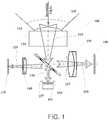
- FIG. 1illustrates an exemplary system layout 100 in accordance with the present invention for a dual-sensor wide-FOV foveated imaging system.
- the systemcontains two subsystems: the wide-FOV imaging subsystem and the foveated imaging subsystem.
- the wide-FOV imaging subsystemcontains an objective lens 110, a beamsplitter 120, a stop 127, a wide-FOV imaging lens 130, and an imaging sensor 140.
- the foveated imaging subsystemcontains an objective lens 110, a beamsplitter 120, a scanning mirror 150, a stop 137, a foveated imaging lens 160, and an imaging sensor 170.
- the two imaging subsystemsshare the same objective lens 110, as well as the optical path 115.
- the light within the FOV 105is captured by the objective lens 110.
- the optical path 115is split into two different paths by the beamsplitter 120: the wide-FOV imaging path 125 and the foveated imaging path 135.
- the wide-FOV imaging path 125the wide-FOV imaging lens 130 images the entire visual field within the FOV 105 captured by the objective lens 110 on wide FOV imaging sensor 140.
- the scanning mirror 150placed at or near the position of the stop 137 and reflects some rays within the FOV 105 captured by the objective lens 110.
- the objective lens 110may be a group of rotationally symmetric lenses to capture a continuous umbrella-like FOV, or near-hemispherical-shape FOV, or near-spherical-shape FOV.
- the objective lens 110could also contain a curved mirror surface along with necessary rotational symmetric lenses to capture a ring-like panoramic FOV.
- the curved mirrorcould be a spherical mirror, a parabolic mirror, a hyperbolic mirror, a conical mirror, an elliptical mirror, or aspherical mirror with or without symmetry or alike.
- the imaging sensors 140 and 170can be any light sensing device containing an array of light sensing units (pixels) that converts photons into electronic signals, including, but not limited to, a charge-couple device (CCD), or a complementary metal-oxide-semiconductor (CMOS) or other type of light sensing devices.
- the scanning mirror 150can be any type of fast moving mirror devices whose scanning motion can be electronically controlled, including, but not limited to, voice coil mirror, piezoelectric mirror, Micro- Electro-Mechanical System (MEMS) mirror or other type of scanning mirrors.
- the beamsplitter 120could be in form of a cube or a plate and could be a non-polarized beamsplitter or a polarized beamsplitter.
- a quarter-wave platemay be used along with the beamsplitter to increase the light efficiency.
- the quarter-wave platemay be positioned in the space between the beamsplitter 120 and the stop 137. Additional polarizers may be used in both the foveated imaging path 135 and the wide-FOV imaging path 125 to reduce the crosstalk between two paths.
- the present inventioncombines two imaging subsystems into one integrated system, where two imaging subsystem share the same objective lens, which may result in a compact and lightweight system.
- the stop 137 in the foveated imaging subsystemis optically conjugate with the stop 127 in the wide-FOV imaging subsystem through the beamsplitter 120.
- the wide-FOV imaging subsystemcaptures a wide view field while the foveated imaging subsystem captures one or a few selected portions of the said wide view field and yields very high resolution videos to enable accurate target recognition.
- the present inventionhas the advantages of being relatively low-cost, compact, low power consumption, low data bandwidth demand as well as uncompromised high performance in terms of FOV, resolution, and real-time acquisition.
- the scanning mirrormay be a dual axis scanning unit 252 for continuously sampling the wide-FOV through tilting motions 253 and 254 along X and Y axes as illustrated in Fig. 2a .
- the scanning mirrormay also be a single axis scanning unit 255 mounted on a rotational stage 256 or with ability of rotating along the Z axis as show in Fig. 2b , in which the mirror samples the wide-FOV through a tilt motion 257 along the Y axis and a rotation motion 258 along the Z axis.
- the present inventionuses a regular imaging system structure where the optical stop is inside the imaging system with a group of lenses are in front of the stop and a group of lenses are behind the stop.
- the advantages of using the regular imaging system structure over the afocal system in the prior artare:
- the present inventionuses a pair of optical conjugated stops which are inside the imaging system and created through a beamsplitter and located in the wide field of view and foveated view optical paths, respectively.
- the stopis placed at the entrance to an afocal system, and the image of the stop created through the afocal system is on the other side of the afocal system.
- the scanning mirroris controllable only through X and Y tilt axes.
- the scanning mirrormay also be configured to use an X or Y tilt and Z rotation instead.
- Figure 3schematically illustrates an exemplary design 300 of the present invention utilizing only the rotationally symmetric lens to capture an umbrella-like FOV 305.
- the objective lens 310contains only a planar-concave lens element.
- a three-element lensis used as the wide-FOV imaging lens 330.
- a dual-axis high-speed scanning mirror 350which scans in both X and Y directions, is placed near the stop 337 for sampling a Region of Interest (ROI) in the FOV 305.
- the beamsplitter 320is a wire-grid type polarized beamsplitter.
- a quarter-wave plate 380is placed between the beamsplitter 320 and the scanning mirror 350 to change the polarization of the light after passing through the wave plate two times.
- the foveated imaging lens 360may use a cemented doublet. To further improve the system optical performance, more lens elements may be added in both the foveated imaging path and the wide-FOV imaging path before or after the stops.
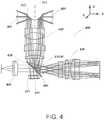
- Figure 4schematically illustrates an exemplary design 400 of the present invention utilizing a curved mirror to capture a ring-like panoramic FOV 405.
- the objective lens 410contains 5 optical elements.
- the first element in the objective lens 410is a curved mirror 412.
- the optical surface of the curved mirror 412is a rotational symmetric mirror surface whose surface profile may be described by a 1-dimmentional polynomial swept 360 degree along its rotational axis 414.
- a four-element lensis used as the wide-FOV imaging lens 430.
- a single-axis high-speed scanning mirror 450is mounted on a rotation stage and is placed near the stop 437 to scan the panoramic FOV 405 through a tilting motion and a rotating motion as described in connect to Fig. 2b .
- the beamsplitter 420may utilize a polarized beamsplitter.
- a quarter-wave plate 480is placed between the beamsplitter 420 and the scanning mirror 450 to change the polarization of the light after passing through the wave plate two times.
- the foveated imaging lens 460may use a cemented doublet. To further improve the system optical performance, more lens elements may be added in both the foveated imaging path and the wide-FOV imaging path before or after the stops.
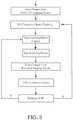
- FIG. 5depicts a block diagram of an example of an image processing pipeline necessary for the present invention.
- an event/object detection algorithmis necessary to process the wide-FOV image to find the region (s) of interest (Rol).
- a signal along with the position (angle) information of the ROIis sent to the fast scanning mirror to resample the region of interest with the foveated imaging sensor.
- An image analysis algorithmis then applied to the foveated image to collect detail information regarding the ROI. The analysis result will determine whether it is necessary to track the region and/or take further actions.
- one or a few imagesmay not be sufficient to characterize an ROI, it is necessary to continue tracking the ROI in the panoramic view, additional to the tracking with the scanning mirror.
- Figure 6schematically illustrates a design layout 600 of an exemplary optical system containing multiple imaging units for extending system FOV.
- the exemplary systemcomprises at least two wide-FOV foveated imaging devices clustered together to capture a designated FOV larger than that of a single unit.
- 4 wide-FOV foveated imaging devices 682-688are used to extent the overall FOV to 360 degree.
- the imaging unitsare mounted together with their FOV pointing away from each other. To eliminate the blind spot in the overall FOV of the system 600, it is desired that the imaging units are mounted in such a way that there is FOV overlap between any two neighboring units.
- the FOV boundary 692 of the unit 682must intersect with the FOV boundary 694 of the unit 684 at certain distance from the imaging units to ensure there is no FOV gap between two units beyond the said distance from the imaging units.
- the exemplary system of Fig. 6does not possess a single viewpoint.
- a single viewing pointmeans that all the imaging units in the cluster effectively capture the entire visual field from a common viewing position, while the imaging units in a multi-viewing-point cluster capture the imaging field from displaced viewing positions. For certain applications, it is desired that the entire imaging field must be captured from a single viewing point.
- a multi-faceted mirrormay be used to virtually co-locate the viewpoints of all the imaging units in the cluster system to a single viewpoint.
Landscapes
- Physics & Mathematics (AREA)
- General Physics & Mathematics (AREA)
- Optics & Photonics (AREA)
- Engineering & Computer Science (AREA)
- Multimedia (AREA)
- Signal Processing (AREA)
- Spectroscopy & Molecular Physics (AREA)
- Human Computer Interaction (AREA)
- Theoretical Computer Science (AREA)
- General Engineering & Computer Science (AREA)
- Software Systems (AREA)
- Computer Graphics (AREA)
- Computer Hardware Design (AREA)
- Lenses (AREA)
- Studio Devices (AREA)
- Stereoscopic And Panoramic Photography (AREA)
- Eyeglasses (AREA)
- Control Of Indicators Other Than Cathode Ray Tubes (AREA)
- Instrument Panels (AREA)
- Camera Bodies And Camera Details Or Accessories (AREA)
- Cameras In General (AREA)
- Telescopes (AREA)
- Optical Elements Other Than Lenses (AREA)
- Liquid Crystal Display Device Control (AREA)
- Closed-Circuit Television Systems (AREA)
Description
- This application claims priority to
U.S. Provisional Application No. 61/620,581, filed on April 5, 2012 U.S. Provisional Application No. 61/620,574, filed on April 5, 2012 - The present invention relates generally to wide-Field of View (FOV) imaging devices, and more particularly, but not exclusively, to dual resolution wide FOV imaging system which is capable of simultaneously capturing a large FOV and a small FOV inside the said large FOV with much higher resolution.
- Real-time acquisition of high-resolution, wide field of view (FOV) and high dynamic range (HDR) images is essential for many military and civilian surveillance applications. For instance, there is an urgent need for an omnidirectional imaging system in many surveillance applications where the system, with sufficient resolution and frame rate, can monitor the activities in all directions simultaneously across a very large operating field (e.g. spherical or complimentary hemispherical coverage) while being able to rapidly zoom into one or multiple objects of interest for reliable identification and characterization of the objects. Such a sensor needs to provide both excellent situational awareness and adequate detail resolvability. This type of sensors, if available, can find myriads of applications in both military and commercial markets.
- However, when designing an optical imaging system, finite sensor resolution and data bandwidth impose limits on the spatial resolution and FOV achievable in state-of-the-art imaging systems. There is a well-known inherent tradeoff between the FOV and the resolving power for most conventional imaging techniques with a fixed number of pixels: the wider the FOV, the lower the resolving power. Using the traditional cluster-based omnidirectional cameras as an example, in order to achieve a 1 arc minute (-300 micro-rad) angular resolution, it requires at least 50 small FOV cameras (e.g. FOV: 33° x 25°) with a 5-Mega pixel sensor on each to cover a spherical field of 360° x 360°, which results in a minimum of 250 Mega pixels to be captured, stored and transmitted for a single spherical panoramic image, barring any pixel loss and FOV overlap. To achieve an angular resolution of 2 arc seconds requires a prohibitive number of cameras in the order of thousands to cover a spherical field. As a result, the cost and size of a camera-cluster-based system will be unacceptable for many surveillance applications, not mentioning that clustering over thousands of high-resolution cameras imposes great challenges to the state-of-the-art data management and image processing technologies.
- Foveation techniques can actively track and capture a region of interest with high resolution sensor without losing the imaging capability of the peripheral area, similar to the foveation properties of the human vision system. Various imaging systems have been developed to explore the potential of applying the foveation technique in imaging applications. For example, Sandini et al. developed a retina-like CMOS sensor with spatially-variant resolution to mimic the human retina (G. Sandini, P. Questa, D. Scheffer and A. Mannucci, "A Retina-like CMOS sensor and its applications," Proceedings of IEEE Workshop on Sensor Array and Multichannel Signal Process. (2000), pp. 514-9). Martinez and Wick proposed to use a liquid crystal spatial light modulator to dynamically correct the aberrations at the foveated region inside a wide FOV of imaging system (T. Martinez, D. V. Wick and S. R. Restaino, "Foveated, wide field-of-view imaging system using a liquid crystal spatial light modulator," Opt. Express 8, 555-60 (2001); D. V. Wick, T. Martinez, S. R. Restaino and B. R. Stone, "Foveated imaging demonstration," Opt. Express 10, 60-5 (2002)). The aforementioned approaches use only single-sensor to capture both the peripheral region and the foveated region which limits the overall information throughput of the system. Alternatively, Hua and Liu proposed a dual-sensor approach to the foveation imaging technology where two separate sensors are used to capture the peripheral region and the foveated region (Hong Hua and Sheng Liu, "Dual-Sensor foveated imaging system," APPLIED OPTICS, Vol. 47, No.3, 317-327, 2008). Comparing with the single sensor approach, the dual sensor approach uses two different sensors which can be in different size and different resolution, which has potential to yield high information throughput with low-cost detectors. The main dis-advantage of the dual-sensor approach is that the system employs an afocal system structure which usually has a limited ability to achieve large peripheral FOV and often results in a bulky system.
- Japanese patent application published
JP 2004 153605 A - The present invention discloses a foveated imaging system in accordance with the subject-matter of appended
independent claim 1 and dependent claims 2-19. - The present invention also discloses a method of controlling a target region of a foveated image in accordance with the subject-matter of appended independent claim 20.
- The present invention concerns a dual-sensor wide-FOV foveated imaging technique which is capable of acquiring wide-FOV videos of a surrounding space in real time and simultaneously obtaining very high resolution, high-magnification foveated images of multiple targets at high frame rate. The wide-FOV video, with appropriate resolution and frame rate, enables the real-time capability of simultaneously observing a surrounding space for acquiring, detecting, and tracking imminent threats posed by objects, while the high resolution foveated videos are focused on multiple small portions of the wide FOV in real time with substantially higher resolution to enable crucial target recognition and characterization. The region of interest (Rol) of the foveated view can be steered in real time to any part of the wide FOV image. These capabilities are analogous to the searching, tracking, and foveation functions of the human visual system. By integrating the foveation capability into a wide-FOV imaging system, the present invention is able to capture a wide viewing field up to 360° x 360° with high angular resolution.
- The present invention typically contains two subsystems: the wide-FOV imaging subsystem and the foveated imaging subsystem; and two subsystems are integrated as one system, where two imaging subsystems share the same objective lens, which may result in a compact and lightweight system design. The stop in the foveated imaging subsystem is optically conjugate with the stop in the wide-FOV imaging subsystem through the beamsplitter. For the present invention, the wide-FOV imaging subsystem captures a wide view field while the foveated imaging subsystem captures one or a few
- selected portions of the said wide view field and yields very high resolution videos to enable accurate target recognition. Compared with state-of-the-art surveillance systems, the present invention has the advantages of being relatively low-cost, compact, low power consumption, low data bandwidth demand as well as uncompromised high performance in terms of FOV, resolution, and real-time acquisition.
- The objective lens of the present invention may utilize the rotationally symmetric refractive optical elements to capture an umbrella-like FOV or utilize a curved mirror along with necessary rotationally symmetric refractive optical elements to capture a ring-like panoramic FOV. The scanning mirror of the present invention may be a dual-axis scanning mirror to sample the wide-FOV using two tilting motions or may be a single-axis scanning mirror to sample the wide-FOV using a combined motion of tilting and rotation.
- In one aspect of the present invention, the exemplary system may integrate multiple wide-FOV foveated imaging units to achieve a FOV much larger than that of a single unit. The integrated system may or may not possess single viewpoint properties. When a single viewpoint property is desired, a multi-faceted mirror may be used to virtually co-locate the viewpoints of all the imaging units in the integrated system to a single viewpoint.
- The foregoing summary and the following detailed description of exemplary embodiments of the present invention may be further understood when read in conjunction with the appended drawings, in which:
Figure 1 schematically illustrates an exemplary optical system in accordance with the present invention.Figure 2 schematically illustrates two types of motions of the scanning mirror used in accordance with the present invention.Figure 3 schematically illustrates an exemplary design of the aforementioned optical system in accordance with the present invention.Figure 4 schematically illustrates another exemplary design of the aforementioned optical system in accordance with the present invention containing a curved mirror surface.Figure 5 depicts a block diagram of an example of an image processing pipeline in accordance with the present invention.Figure 6 schematically illustrates a design layout of an exemplary optical system containing multiple imaging units in accordance with the present invention.- The embodiments according to the present invention will be fully described with respect to the attached drawings. The descriptions are set forth in order to provide an understanding of the invention. However, it will be apparent that the invention can be practiced without these details. Furthermore, the present invention may be implemented in various forms. However, the embodiments of the present invention described below shall not be constructed as limited to the embodiments set forth herein. Rather, these embodiments, drawings and examples are illustrative and are meant to avoid obscuring the invention.
- A primary embodiment of the present invention comprises, a foveated imaging system (100), capable of capturing a wide field of view image and a foveated image, where the foveated image is a controllable region of interest of the wide field of view image, the system comprising:
- a. an objective lens (110), facing an external scene, configured to receive the incoming light from the external scene and to focus the light upon a beamsplitter;
- b. a beamsplitter (120), configured to split incoming light from an external scene into a wide field of view imaging path (125) and a foveated imaging path (135);
- c. a wide field of view imaging path (125), the wide field of view imaging path comprising:
- i. a first stop (127), which limits the amount of light received in the wide field of view path from the beamsplitter (120);
- ii. a wide field-of-view imaging lens (130), configured to receive light from the stop (127) and form a wide field view image on a wide field of view imaging sensor;
- iii. a wide field-of-view imaging sensor (140), configured to receive light from the wide field of view imaging lens (130);
- d. a foveated view imaging path (135), the foveated view imaging path comprising :
- i. a second stop (137), which limits the amount of light received in the foveated imaging path from the beamsplitter (120);
- ii. a scanning mirror (150), capable of being controlled to reflect the light from the beamsplitter (120);
- iii. a foveated imaging lens (160), configured to receive a portion of the light, associated with a region of interest of the external scene, from the scanning mirror (150) and form a foveated image on a foveated imaging sensor; and
- iv. a foveated imaging sensor (170), configured to receive light from the foveated imaging lens (160);
- In some embodiments, the incoming light from the external scene passes through the objective lens (110) to the beamsplitter (120), where the beamsplitter (120) divides the light into the two optical paths, a wide field of view imaging path (125) and a foveated imaging path (135) . In the wide field of view path, the light passes through the first stop (127) to the wide field of view imaging lens (130) along the wide field of view imaging path (125). The lens focuses the wide field of view image upon the wide field of view imaging sensor (140). On the foveated view imaging path, the light passes through the second stop (137) to the scanning mirror (150) along the foveated imaging path (135), where the scanning mirror (150) reflects a region of interest toward the foveated imaging lens (160) through the beam splitter (120). The foveated imaging lens (160) focuses the foveated image upon the foveated imaging sensor (170).
- In some embodiments, the objective lens (110) is disposed on the front of the system. The beamsplitter (120) is disposed adjacent to objective lens receiving light from the objective lens. The beamsplitter (120) divides the light into the two optical paths, a wide field of view imaging path (125) and a foveated imaging path (135). The first stop (127) is in optical communication with the beamsplitter (120) along the wide field of view imaging path (125) and the second stop (137) is in optical communication with the beamsplitter (120) along the foveated imaging path (135). The scanning mirror (150) is disposed near or at the position of the second stop (137), where it receives light from the beamsplitter (120) along the foveated imaging path (135) and reflects the light back to the beamsplitter (120). The wide-field of view imaging lens (130) is disposed to face the first stop (127) along the wide field of view imaging path (125), where it receives light from the beamsplitter (120) through the first stop (127) along the wide field of view path (125). The foveated imaging lens (160) is disposed to face the beamsplitter (120), where it receives light from the beamsplitter (120) reflected from the scanning mirror (150) along the foveated imaging path (135). The wide-field of view imaging sensor (140) is disposed to face the wide field of view imaging lens (130). The foveated imaging sensor (170) is disposed to face the foveated imaging lens (160). The two images are recorded by the sensors, a wide field of view image and a high resolution image of the region of interest within it.
- In some embodiments, the objective lens (110) is located on the front of the system. The beam splitter (120) is located between the objective lens and the stop (137) facing the objective lens (110) and the scanning mirror (150) so that it receives light from the objective lens. The scanning mirror (150) is located behind the beam splitter, where it receives light from the foveated image path of the beamsplitter (120) and reflects it back to the beamsplitter (120). The wide-field of view imaging lens (130) faces the wide field of view image path of the beam splitter, while the foveated imaging lens (160) faces the foveated image optical path of the beam splitter (120). The wide-field of view imaging sensor (140) faces the wide-field-of-view imaging lens (130), and the foveated imaging sensor (170) is faces the foveated imaging lens (160).
- In some embodiments, the incoming light from the external scene passes through the objective lens (110) to the beamsplitter, whereupon the beam splitter (120) transmits one copy of the light to the wide field of view lens (130) and a second copy of the light to the scanning mirror (150). The scanning mirror (150) reflects a region of interest back to the beam splitter (120), and the beam splitter reflects the light to the foveated imaging lens (160). Meanwhile, the wide field of view imaging lens (130) transmits the light in the wide field of view imaging path (125) to the wide field of view image sensor (140). The foveated imaging lens (160) transmits the light in the foveated imaging path (135) to the foveated imaging sensor (170). Thus the two images are recorded by the sensors, a wide field of view image and a high resolution image of the region of interest within it.
Figure 1 illustrates anexemplary system layout 100 in accordance with the present invention for a dual-sensor wide-FOV foveated imaging system. The system contains two subsystems: the wide-FOV imaging subsystem and the foveated imaging subsystem. The wide-FOV imaging subsystem contains anobjective lens 110, abeamsplitter 120, astop 127, a wide-FOV imaging lens 130, and animaging sensor 140. The foveated imaging subsystem contains anobjective lens 110, abeamsplitter 120, ascanning mirror 150, astop 137, afoveated imaging lens 160, and animaging sensor 170. In thisexemplary layout 100, the two imaging subsystems share the sameobjective lens 110, as well as theoptical path 115. The light within theFOV 105 is captured by theobjective lens 110. After the light passes through theobjective lens 110, theoptical path 115 is split into two different paths by the beamsplitter 120: the wide-FOV imaging path 125 and thefoveated imaging path 135. In the wide-FOV imaging path 125, the wide-FOV imaging lens 130 images the entire visual field within theFOV 105 captured by theobjective lens 110 on wideFOV imaging sensor 140. In thefoveated imaging path 135, thescanning mirror 150 placed at or near the position of thestop 137 and reflects some rays within theFOV 105 captured by theobjective lens 110. By tilting thescanning mirror 150 instantaneously towards the direction of interest, rays from the interested sub-FOV of theFOV 105 are redirected to thebeamsplitter 120 and reflected toward thefoveated imaging lens 160 and imaged on thefoveated imaging sensor 170.- In this
exemplary layout 100, theobjective lens 110 may be a group of rotationally symmetric lenses to capture a continuous umbrella-like FOV, or near-hemispherical-shape FOV, or near-spherical-shape FOV. Theobjective lens 110 could also contain a curved mirror surface along with necessary rotational symmetric lenses to capture a ring-like panoramic FOV. The curved mirror could be a spherical mirror, a parabolic mirror, a hyperbolic mirror, a conical mirror, an elliptical mirror, or aspherical mirror with or without symmetry or alike. Theimaging sensors scanning mirror 150 can be any type of fast moving mirror devices whose scanning motion can be electronically controlled, including, but not limited to, voice coil mirror, piezoelectric mirror, Micro- Electro-Mechanical System (MEMS) mirror or other type of scanning mirrors. Thebeamsplitter 120 could be in form of a cube or a plate and could be a non-polarized beamsplitter or a polarized beamsplitter. When a polarized beamsplitter is used, a quarter-wave plate may be used along with the beamsplitter to increase the light efficiency. The quarter-wave plate may be positioned in the space between thebeamsplitter 120 and thestop 137. Additional polarizers may be used in both thefoveated imaging path 135 and the wide-FOV imaging path 125 to reduce the crosstalk between two paths. - As one of its benefits, the present invention combines two imaging subsystems into one integrated system, where two imaging subsystem share the same objective lens, which may result in a compact and lightweight system. The
stop 137 in the foveated imaging subsystem is optically conjugate with thestop 127 in the wide-FOV imaging subsystem through thebeamsplitter 120. For the present invention, the wide-FOV imaging subsystem captures a wide view field while the foveated imaging subsystem captures one or a few selected portions of the said wide view field and yields very high resolution videos to enable accurate target recognition. Compared with state-of-the-art surveillance systems, the present invention has the advantages of being relatively low-cost, compact, low power consumption, low data bandwidth demand as well as uncompromised high performance in terms of FOV, resolution, and real-time acquisition. - In one aspect of the present invention, the scanning mirror may be a dual
axis scanning unit 252 for continuously sampling the wide-FOV through tiltingmotions Fig. 2a . The scanning mirror may also be a singleaxis scanning unit 255 mounted on arotational stage 256 or with ability of rotating along the Z axis as show inFig. 2b , in which the mirror samples the wide-FOV through atilt motion 257 along the Y axis and arotation motion 258 along the Z axis. - Compared to the dual sensor approach in the prior arts, the present invention uses a regular imaging system structure where the optical stop is inside the imaging system with a group of lenses are in front of the stop and a group of lenses are behind the stop. The advantages of using the regular imaging system structure over the afocal system in the prior art are:
- a. Allowing a more compact system and easier to design given that certain optical aberrations may be corrected by using lenses at both side of the stop;
- b. Capable of achieving a much bigger FOV than that of an afocal system while maintaining a compact form factor.
- In another significant aspect, the present invention uses a pair of optical conjugated stops which are inside the imaging system and created through a beamsplitter and located in the wide field of view and foveated view optical paths, respectively. In the prior art, the stop is placed at the entrance to an afocal system, and the image of the stop created through the afocal system is on the other side of the afocal system.
- The yet another significant aspect, in the prior art, the scanning mirror is controllable only through X and Y tilt axes. In the present invention the scanning mirror may also be configured to use an X or Y tilt and Z rotation instead.
Figure 3 schematically illustrates anexemplary design 300 of the present invention utilizing only the rotationally symmetric lens to capture an umbrella-like FOV 305. In thisexemplary design 300, theobjective lens 310 contains only a planar-concave lens element. A three-element lens is used as the wide-FOV imaging lens 330. A dual-axis high-speed scanning mirror 350, which scans in both X and Y directions, is placed near thestop 337 for sampling a Region of Interest (ROI) in theFOV 305. Thebeamsplitter 320 is a wire-grid type polarized beamsplitter. A quarter-wave plate 380 is placed between thebeamsplitter 320 and thescanning mirror 350 to change the polarization of the light after passing through the wave plate two times. In one of exemplary implementations, thefoveated imaging lens 360 may use a cemented doublet. To further improve the system optical performance, more lens elements may be added in both the foveated imaging path and the wide-FOV imaging path before or after the stops.Figure 4 schematically illustrates anexemplary design 400 of the present invention utilizing a curved mirror to capture a ring-likepanoramic FOV 405. In thisexemplary design 400, theobjective lens 410 contains 5 optical elements. The first element in theobjective lens 410 is acurved mirror 412. The optical surface of thecurved mirror 412 is a rotational symmetric mirror surface whose surface profile may be described by a 1-dimmentional polynomial swept 360 degree along itsrotational axis 414. A four-element lens is used as the wide-FOV imaging lens 430. A single-axis high-speed scanning mirror 450 is mounted on a rotation stage and is placed near thestop 437 to scan thepanoramic FOV 405 through a tilting motion and a rotating motion as described in connect toFig. 2b . Thebeamsplitter 420 may utilize a polarized beamsplitter. A quarter-wave plate 480 is placed between thebeamsplitter 420 and thescanning mirror 450 to change the polarization of the light after passing through the wave plate two times. In one of exemplary implementation, thefoveated imaging lens 460 may use a cemented doublet. To further improve the system optical performance, more lens elements may be added in both the foveated imaging path and the wide-FOV imaging path before or after the stops.Figure 5 depicts a block diagram of an example of an image processing pipeline necessary for the present invention. Firstly, an event/object detection algorithm is necessary to process the wide-FOV image to find the region (s) of interest (Rol). Once a region of interest is identified, a signal along with the position (angle) information of the ROI is sent to the fast scanning mirror to resample the region of interest with the foveated imaging sensor. An image analysis algorithm is then applied to the foveated image to collect detail information regarding the ROI. The analysis result will determine whether it is necessary to track the region and/or take further actions. Sometimes, one or a few images may not be sufficient to characterize an ROI, it is necessary to continue tracking the ROI in the panoramic view, additional to the tracking with the scanning mirror.Figure 6 schematically illustrates a design layout 600 of an exemplary optical system containing multiple imaging units for extending system FOV. The exemplary system comprises at least two wide-FOV foveated imaging devices clustered together to capture a designated FOV larger than that of a single unit. In thedesign layout 600, 4 wide-FOV foveated imaging devices 682-688 are used to extent the overall FOV to 360 degree. The imaging units are mounted together with their FOV pointing away from each other. To eliminate the blind spot in the overall FOV of the system 600, it is desired that the imaging units are mounted in such a way that there is FOV overlap between any two neighboring units. Usingunits FOV boundary 692 of theunit 682 must intersect with theFOV boundary 694 of theunit 684 at certain distance from the imaging units to ensure there is no FOV gap between two units beyond the said distance from the imaging units.- In one aspect of the present invention related to
Figure 6 , the exemplary system ofFig. 6 does not possess a single viewpoint. A single viewing point means that all the imaging units in the cluster effectively capture the entire visual field from a common viewing position, while the imaging units in a multi-viewing-point cluster capture the imaging field from displaced viewing positions. For certain applications, it is desired that the entire imaging field must be captured from a single viewing point. To achieve single viewpoint property, a multi-faceted mirror may be used to virtually co-locate the viewpoints of all the imaging units in the cluster system to a single viewpoint.
Claims (20)
- A foveated imaging system (100), capable of receiving incoming light from an external scene and capturing a wide field of view image and a foveated image controlled from a scanning mirror (150) in a foveated imaging path (135), where the foveated image is a controllable region of interest within the wide field of view image, the systemcharacterized by:a) an objective lens (110), facing an external scene, configured to receive the incoming light from the external scene and to focus the light upon a beamsplitter (120) that divides the incoming light into a wide field of view imaging path (125) and a foveated imaging path (135);b) a beamsplitter (120) disposed adjacent to the objective lens (110), configured to split the incoming light from the external scene into the wide field of view imaging path (125) and the foveated imaging path (135);c) a wide field of view imaging path (125), the wide field of view imaging path comprising:i. a first stop (127) in optical communication with the beamsplitter (120) along the wide field of view imaging path (125), which limits the amount of light received in the wide field of view path (125) from the beamsplitter (120);ii. a wide field-of-view imaging lens (130) disposed to face the first stop (127) along the wide field of view imaging path (125), configured to receive light from the first stop (127) and form a wide field view image on a wide field of view imaging sensor (140);iii. a wide field-of-view imaging sensor (140) disposed to face the wide field of view imaging lens (130), configured to receive light from the wide field of view imaging lens (130);d) a foveated view imaging path (135), the foveated view imaging path comprising :whereupon the incoming light from the external scene passes through the objective lens (110) to the beamsplitter (120), whereupon the beamsplitter (120) divides the light into the two optical paths, a wide field of view imaging path (125) and a foveated imaging path(135), whereupon the light passes through the first stop (127) to the wide field of view imaging lens (130) along the wide field of view imaging path (125), where the lens focuses the wide field of view image upon the wide field of view imaging sensor (140), whereupon the light passes through the second stop (137) to the scanning mirror (150) along the foveated imaging path (135), whereupon the scanning mirror (150) reflects a region of interest toward the foveated imaging lens (160) through the beam splitter (120), whereupon the foveated imaging lens (160) focuses the foveated image upon the foveated imaging sensor (170); whereupon the two images are recorded by the sensors, a wide field of view image and a high resolution image of the region of interest within it.i. a second stop (137) in optical communication with the beamsplitter (120) along the foveated imaging path (135), which limits the amount of light received in the foveated imaging path from the beamsplitter (120);ii. a scanning mirror (150) disposed near or at the position of the second stop (137), capable of being controlled to reflect the light from the beamsplitter (120) along foveated image path (135) and reflects light back to the beamsplitter (120);iii. a foveated imaging lens (160) disposed to face the beamsplitter (120), configured to receive a portion of the light from the beamsplitter (120) associated with a region of interest of the external scene reflected from the scanning mirror (150) and form a foveated image on a foveated imaging sensor; andiv. a foveated imaging sensor (170) disposed to face the foveated imaging lens (160), configured to receive light from the foveated imaging lens (160);
- The foveated imaging system according to any one of the preceding claims, where the objective lens is a group of rotationally symmetric lenses to capture an umbrella-like or hemispherical shaped field of view.
- The foveated imaging system according to any one of claims 1-2, where the objective lens utilizes a curved mirror along with necessary rotationally symmetric refractive optical elements to capture a ring-like panoramic field of view.
- The foveated imaging system according to any one of claims 1-2, where the imaging sensors (140) and (170) are any light sensing device containing an array of light sensing units (pixels) that converts photons into electronic signals, including, but not limited to, a charge-couple device (CCD), or a complementary metal-oxide-semiconductor (CMOS) or other type of light sensing devices.
- The foveated imaging system according to any one of claims 1-2, where the scanning mirror (150) is any type of fast moving mirror device whose scanning motion can be electronically controlled, including, but not limited to, voice coil mirror, piezoelectric mirror, Micro-Electro-Mechanical System (MEMS) mirror or other type of scanning mirrors.
- The foveated imaging system according to any one of claims 1-2, where the scanning mirror is a dual axis scanning unit (252) capable of continuously sampling the wide-FOV through tilting motions (253) and (254) along X and Y axes.
- The foveated imaging system according to any one of claims 1-2, where the scanning mirror is a rotating single axis scanning unit (255), in which the mirror samples the wide-FOV through a tilt motion (257) along the Y axis and a rotation motion (258) along the Z axis.
- The foveated imaging system according to any one of claims 1-2, where the aperture of the scanning mirror performs the function of the second stop (137) to limits the amount of light received in the foveated imaging path from the beamsplitter;
- The foveated imaging system according to any one of claims 1-2, where the beamsplitter (120) is in form of a cube or a plate and could be a non-polarized beamsplitter or a polarized beamsplitter.
- The foveated imaging system according to any one of claims 1-2, where the beamsplitter is a polarized beamsplitter, and a quarter-wave plate is used along with the beamsplitter to increase the light efficiency, where the quarter-wave plate is positioned in the between the beamsplitter (120) and the scanning mirror (150).
- The foveated imaging system according to any one of claims 1-2, where additional polarizers are used in both the foveated imaging path (135) and the wide-FOV imaging path (125) to reduce the crosstalk between two paths.
- The foveated imaging system according to any one of claims 1-2, where the foveated imaging lens is a group of rotationally symmetric lenses that magnify the foveated image.
- The foveated imaging system according to any one of claims 1-2, where the foveated imaging lens may contain aspherical reflective or refractive surfaces.
- The foveated imaging system according to any one of claims 1-2, where the wide field of view imaging lens is a group of rotationally symmetric lenses that magnify the wide field of view image.
- The foveated imaging system according to any one of claims 1-2, where the wide field of view imaging lens may contain aspherical reflective or refractive surfaces.
- The foveated imaging system according to any one of claims 1-15, where the system comprises at least two wide-FOV foveated imaging devices clustered together to capture a designated FOV larger than that of a single unit.
- The system according to the claim 16, where the multiple wide-FOV imaging devices are placed at multiple viewpoints without FOV gap, such as to capture a continuous wide-FOV image.
- The system according to the claim 17, where the multiple wide-FOV imaging devices are colocated at a common virtual viewpoint through a multi-facet mirror as if the wide-FOV image is captured from a single viewpoint.
- The foveated imaging system according to any one of claims 1-2, where the scanning mirror is controlled by a scanning mirror controller (151) where the scanning mirror controller has an electronic interface that can communicate with a microprocessor.
- A method of controlling a target region of a foveated image, within a wide field of view image using a foveated image system according to claim 1 the method comprises the steps of:a) receiving images from the wide field of view image sensor;b) detecting a target region of interest;c) generating commands to a fast scanning mirror control, corresponding to pointing the scanning mirror at the target of interest;d) receiving images from the foveated image sensor;e) characterizing an object in the foveated image.
Priority Applications (1)
| Application Number | Priority Date | Filing Date | Title |
|---|---|---|---|
| EP19193685.5AEP3608717B1 (en) | 2012-04-05 | 2013-04-04 | Wide-field of view (fov) imaging devices with active foveation capability |
Applications Claiming Priority (3)
| Application Number | Priority Date | Filing Date | Title |
|---|---|---|---|
| US201261620574P | 2012-04-05 | 2012-04-05 | |
| US201261620581P | 2012-04-05 | 2012-04-05 | |
| PCT/US2013/035293WO2013152205A1 (en) | 2012-04-05 | 2013-04-04 | Wide-field of view (fov) imaging devices with active foveation capability |
Related Child Applications (2)
| Application Number | Title | Priority Date | Filing Date |
|---|---|---|---|
| EP19193685.5ADivision-IntoEP3608717B1 (en) | 2012-04-05 | 2013-04-04 | Wide-field of view (fov) imaging devices with active foveation capability |
| EP19193685.5ADivisionEP3608717B1 (en) | 2012-04-05 | 2013-04-04 | Wide-field of view (fov) imaging devices with active foveation capability |
Publications (3)
| Publication Number | Publication Date |
|---|---|
| EP2841991A1 EP2841991A1 (en) | 2015-03-04 |
| EP2841991A4 EP2841991A4 (en) | 2016-02-10 |
| EP2841991B1true EP2841991B1 (en) | 2020-01-08 |
Family
ID=49301051
Family Applications (5)
| Application Number | Title | Priority Date | Filing Date |
|---|---|---|---|
| EP13772991.9AActiveEP2841991B1 (en) | 2012-04-05 | 2013-04-04 | Wide-field of view (fov) imaging devices with active foveation capability |
| EP19193685.5AActiveEP3608717B1 (en) | 2012-04-05 | 2013-04-04 | Wide-field of view (fov) imaging devices with active foveation capability |
| EP13817261.4AActiveEP2834699B1 (en) | 2012-04-05 | 2013-04-05 | Apparatus for optical see-through head mounted display with mutual occlusion and opaqueness control capability |
| EP20206176.8AActiveEP3796071B1 (en) | 2012-04-05 | 2013-04-05 | Apparatus for optical see-through head mounted display with mutual occlusion and opaqueness control capability |
| EP24154095.4APendingEP4339690A3 (en) | 2012-04-05 | 2013-04-05 | Apparatus for optical see-through head mounted display with mutual occlusion and opaqueness control capability |
Family Applications After (4)
| Application Number | Title | Priority Date | Filing Date |
|---|---|---|---|
| EP19193685.5AActiveEP3608717B1 (en) | 2012-04-05 | 2013-04-04 | Wide-field of view (fov) imaging devices with active foveation capability |
| EP13817261.4AActiveEP2834699B1 (en) | 2012-04-05 | 2013-04-05 | Apparatus for optical see-through head mounted display with mutual occlusion and opaqueness control capability |
| EP20206176.8AActiveEP3796071B1 (en) | 2012-04-05 | 2013-04-05 | Apparatus for optical see-through head mounted display with mutual occlusion and opaqueness control capability |
| EP24154095.4APendingEP4339690A3 (en) | 2012-04-05 | 2013-04-05 | Apparatus for optical see-through head mounted display with mutual occlusion and opaqueness control capability |
Country Status (12)
| Country | Link |
|---|---|
| US (14) | US9851563B2 (en) |
| EP (5) | EP2841991B1 (en) |
| JP (9) | JP6176747B2 (en) |
| KR (11) | KR102404537B1 (en) |
| CN (5) | CN108391033B (en) |
| AU (4) | AU2013243380B2 (en) |
| BR (2) | BR112014024941A2 (en) |
| CA (4) | CA2869781C (en) |
| IL (6) | IL308962A (en) |
| NZ (6) | NZ725322A (en) |
| RU (2) | RU2015156050A (en) |
| WO (2) | WO2013152205A1 (en) |
Families Citing this family (517)
| Publication number | Priority date | Publication date | Assignee | Title |
|---|---|---|---|---|
| GB0522968D0 (en) | 2005-11-11 | 2005-12-21 | Popovich Milan M | Holographic illumination device |
| GB0718706D0 (en) | 2007-09-25 | 2007-11-07 | Creative Physics Ltd | Method and apparatus for reducing laser speckle |
| US9158116B1 (en) | 2014-04-25 | 2015-10-13 | Osterhout Group, Inc. | Temple and ear horn assembly for headworn computer |
| US9715112B2 (en) | 2014-01-21 | 2017-07-25 | Osterhout Group, Inc. | Suppression of stray light in head worn computing |
| US9952664B2 (en) | 2014-01-21 | 2018-04-24 | Osterhout Group, Inc. | Eye imaging in head worn computing |
| US9229233B2 (en) | 2014-02-11 | 2016-01-05 | Osterhout Group, Inc. | Micro Doppler presentations in head worn computing |
| US9400390B2 (en) | 2014-01-24 | 2016-07-26 | Osterhout Group, Inc. | Peripheral lighting for head worn computing |
| US9366867B2 (en) | 2014-07-08 | 2016-06-14 | Osterhout Group, Inc. | Optical systems for see-through displays |
| US9965681B2 (en) | 2008-12-16 | 2018-05-08 | Osterhout Group, Inc. | Eye imaging in head worn computing |
| US20150205111A1 (en) | 2014-01-21 | 2015-07-23 | Osterhout Group, Inc. | Optical configurations for head worn computing |
| US9298007B2 (en) | 2014-01-21 | 2016-03-29 | Osterhout Group, Inc. | Eye imaging in head worn computing |
| US20150277120A1 (en) | 2014-01-21 | 2015-10-01 | Osterhout Group, Inc. | Optical configurations for head worn computing |
| US9335604B2 (en) | 2013-12-11 | 2016-05-10 | Milan Momcilo Popovich | Holographic waveguide display |
| US11726332B2 (en) | 2009-04-27 | 2023-08-15 | Digilens Inc. | Diffractive projection apparatus |
| WO2012136970A1 (en) | 2011-04-07 | 2012-10-11 | Milan Momcilo Popovich | Laser despeckler based on angular diversity |
| WO2016020630A2 (en) | 2014-08-08 | 2016-02-11 | Milan Momcilo Popovich | Waveguide laser illuminator incorporating a despeckler |
| US10670876B2 (en) | 2011-08-24 | 2020-06-02 | Digilens Inc. | Waveguide laser illuminator incorporating a despeckler |
| EP2995986B1 (en) | 2011-08-24 | 2017-04-12 | Rockwell Collins, Inc. | Data display |
| US20150010265A1 (en) | 2012-01-06 | 2015-01-08 | Milan, Momcilo POPOVICH | Contact image sensor using switchable bragg gratings |
| WO2013152205A1 (en)* | 2012-04-05 | 2013-10-10 | Augmented Vision Inc. | Wide-field of view (fov) imaging devices with active foveation capability |
| CN106125308B (en) | 2012-04-25 | 2019-10-25 | 罗克韦尔柯林斯公司 | Device and method for displaying images |
| WO2013167864A1 (en) | 2012-05-11 | 2013-11-14 | Milan Momcilo Popovich | Apparatus for eye tracking |
| US9933684B2 (en) | 2012-11-16 | 2018-04-03 | Rockwell Collins, Inc. | Transparent waveguide display providing upper and lower fields of view having a specific light output aperture configuration |
| US9858721B2 (en) | 2013-01-15 | 2018-01-02 | The University Of North Carolina At Chapel Hill | Methods, systems, and computer readable media for generating an augmented scene display |
| US10209517B2 (en) | 2013-05-20 | 2019-02-19 | Digilens, Inc. | Holographic waveguide eye tracker |
| US10228561B2 (en)* | 2013-06-25 | 2019-03-12 | Microsoft Technology Licensing, Llc | Eye-tracking system using a freeform prism and gaze-detection light |
| US9625723B2 (en)* | 2013-06-25 | 2017-04-18 | Microsoft Technology Licensing, Llc | Eye-tracking system using a freeform prism |
| WO2015015138A1 (en) | 2013-07-31 | 2015-02-05 | Milan Momcilo Popovich | Method and apparatus for contact image sensing |
| WO2015095737A2 (en) | 2013-12-19 | 2015-06-25 | The University Of North Carolina At Chapel Hill | Optical see-through near-eye display using point light source backlight |
| US20150228119A1 (en) | 2014-02-11 | 2015-08-13 | Osterhout Group, Inc. | Spatial location presentation in head worn computing |
| US9841599B2 (en) | 2014-06-05 | 2017-12-12 | Osterhout Group, Inc. | Optical configurations for head-worn see-through displays |
| US9575321B2 (en) | 2014-06-09 | 2017-02-21 | Osterhout Group, Inc. | Content presentation in head worn computing |
| US11227294B2 (en) | 2014-04-03 | 2022-01-18 | Mentor Acquisition One, Llc | Sight information collection in head worn computing |
| US9366868B2 (en) | 2014-09-26 | 2016-06-14 | Osterhout Group, Inc. | See-through computer display systems |
| US9594246B2 (en) | 2014-01-21 | 2017-03-14 | Osterhout Group, Inc. | See-through computer display systems |
| US9529195B2 (en) | 2014-01-21 | 2016-12-27 | Osterhout Group, Inc. | See-through computer display systems |
| US9746686B2 (en) | 2014-05-19 | 2017-08-29 | Osterhout Group, Inc. | Content position calibration in head worn computing |
| US20160019715A1 (en) | 2014-07-15 | 2016-01-21 | Osterhout Group, Inc. | Content presentation in head worn computing |
| US10649220B2 (en) | 2014-06-09 | 2020-05-12 | Mentor Acquisition One, Llc | Content presentation in head worn computing |
| US9448409B2 (en) | 2014-11-26 | 2016-09-20 | Osterhout Group, Inc. | See-through computer display systems |
| US9939934B2 (en) | 2014-01-17 | 2018-04-10 | Osterhout Group, Inc. | External user interface for head worn computing |
| US20150277118A1 (en) | 2014-03-28 | 2015-10-01 | Osterhout Group, Inc. | Sensor dependent content position in head worn computing |
| US9299194B2 (en) | 2014-02-14 | 2016-03-29 | Osterhout Group, Inc. | Secure sharing in head worn computing |
| US9810906B2 (en) | 2014-06-17 | 2017-11-07 | Osterhout Group, Inc. | External user interface for head worn computing |
| US9671613B2 (en) | 2014-09-26 | 2017-06-06 | Osterhout Group, Inc. | See-through computer display systems |
| US10684687B2 (en) | 2014-12-03 | 2020-06-16 | Mentor Acquisition One, Llc | See-through computer display systems |
| US11103122B2 (en) | 2014-07-15 | 2021-08-31 | Mentor Acquisition One, Llc | Content presentation in head worn computing |
| US10254856B2 (en) | 2014-01-17 | 2019-04-09 | Osterhout Group, Inc. | External user interface for head worn computing |
| US10191279B2 (en) | 2014-03-17 | 2019-01-29 | Osterhout Group, Inc. | Eye imaging in head worn computing |
| US9829707B2 (en) | 2014-08-12 | 2017-11-28 | Osterhout Group, Inc. | Measuring content brightness in head worn computing |
| US9651788B2 (en) | 2014-01-21 | 2017-05-16 | Osterhout Group, Inc. | See-through computer display systems |
| US9753288B2 (en) | 2014-01-21 | 2017-09-05 | Osterhout Group, Inc. | See-through computer display systems |
| US12105281B2 (en) | 2014-01-21 | 2024-10-01 | Mentor Acquisition One, Llc | See-through computer display systems |
| US9310610B2 (en) | 2014-01-21 | 2016-04-12 | Osterhout Group, Inc. | See-through computer display systems |
| US20150205135A1 (en) | 2014-01-21 | 2015-07-23 | Osterhout Group, Inc. | See-through computer display systems |
| US12093453B2 (en) | 2014-01-21 | 2024-09-17 | Mentor Acquisition One, Llc | Eye glint imaging in see-through computer display systems |
| US9615742B2 (en) | 2014-01-21 | 2017-04-11 | Osterhout Group, Inc. | Eye imaging in head worn computing |
| US9494800B2 (en) | 2014-01-21 | 2016-11-15 | Osterhout Group, Inc. | See-through computer display systems |
| US11892644B2 (en) | 2014-01-21 | 2024-02-06 | Mentor Acquisition One, Llc | See-through computer display systems |
| US11487110B2 (en) | 2014-01-21 | 2022-11-01 | Mentor Acquisition One, Llc | Eye imaging in head worn computing |
| US11669163B2 (en) | 2014-01-21 | 2023-06-06 | Mentor Acquisition One, Llc | Eye glint imaging in see-through computer display systems |
| US9836122B2 (en) | 2014-01-21 | 2017-12-05 | Osterhout Group, Inc. | Eye glint imaging in see-through computer display systems |
| US9651784B2 (en) | 2014-01-21 | 2017-05-16 | Osterhout Group, Inc. | See-through computer display systems |
| US9766463B2 (en) | 2014-01-21 | 2017-09-19 | Osterhout Group, Inc. | See-through computer display systems |
| US9740280B2 (en) | 2014-01-21 | 2017-08-22 | Osterhout Group, Inc. | Eye imaging in head worn computing |
| US9811152B2 (en) | 2014-01-21 | 2017-11-07 | Osterhout Group, Inc. | Eye imaging in head worn computing |
| US11737666B2 (en) | 2014-01-21 | 2023-08-29 | Mentor Acquisition One, Llc | Eye imaging in head worn computing |
| US9846308B2 (en) | 2014-01-24 | 2017-12-19 | Osterhout Group, Inc. | Haptic systems for head-worn computers |
| US9401540B2 (en) | 2014-02-11 | 2016-07-26 | Osterhout Group, Inc. | Spatial location presentation in head worn computing |
| US12112089B2 (en) | 2014-02-11 | 2024-10-08 | Mentor Acquisition One, Llc | Spatial location presentation in head worn computing |
| US9852545B2 (en) | 2014-02-11 | 2017-12-26 | Osterhout Group, Inc. | Spatial location presentation in head worn computing |
| US11138793B2 (en) | 2014-03-14 | 2021-10-05 | Magic Leap, Inc. | Multi-depth plane display system with reduced switching between depth planes |
| CN103901615B (en)* | 2014-03-14 | 2016-05-25 | 北京理工大学 | Little recessed imaging optical system |
| US10430985B2 (en) | 2014-03-14 | 2019-10-01 | Magic Leap, Inc. | Augmented reality systems and methods utilizing reflections |
| US20160187651A1 (en) | 2014-03-28 | 2016-06-30 | Osterhout Group, Inc. | Safety for a vehicle operator with an hmd |
| US9922667B2 (en) | 2014-04-17 | 2018-03-20 | Microsoft Technology Licensing, Llc | Conversation, presence and context detection for hologram suppression |
| US10529359B2 (en) | 2014-04-17 | 2020-01-07 | Microsoft Technology Licensing, Llc | Conversation detection |
| US9672210B2 (en) | 2014-04-25 | 2017-06-06 | Osterhout Group, Inc. | Language translation with head-worn computing |
| US9423842B2 (en) | 2014-09-18 | 2016-08-23 | Osterhout Group, Inc. | Thermal management for head-worn computer |
| US20150309534A1 (en) | 2014-04-25 | 2015-10-29 | Osterhout Group, Inc. | Ear horn assembly for headworn computer |
| US10853589B2 (en) | 2014-04-25 | 2020-12-01 | Mentor Acquisition One, Llc | Language translation with head-worn computing |
| US9651787B2 (en) | 2014-04-25 | 2017-05-16 | Osterhout Group, Inc. | Speaker assembly for headworn computer |
| US20160137312A1 (en) | 2014-05-06 | 2016-05-19 | Osterhout Group, Inc. | Unmanned aerial vehicle launch system |
| CN104102018B (en)* | 2014-05-08 | 2016-10-05 | 北京理工大学 | Double small recessed local high resolution imaging system |
| CN104007559B (en)* | 2014-05-08 | 2017-05-17 | 北京理工大学 | Foveated imaging system with partial super-resolution scanning function |
| US10663740B2 (en) | 2014-06-09 | 2020-05-26 | Mentor Acquisition One, Llc | Content presentation in head worn computing |
| US10359736B2 (en) | 2014-08-08 | 2019-07-23 | Digilens Inc. | Method for holographic mastering and replication |
| WO2016042283A1 (en) | 2014-09-19 | 2016-03-24 | Milan Momcilo Popovich | Method and apparatus for generating input images for holographic waveguide displays |
| EP3198192A1 (en) | 2014-09-26 | 2017-08-02 | Milan Momcilo Popovich | Holographic waveguide opticaltracker |
| WO2016054079A1 (en) | 2014-09-29 | 2016-04-07 | Zyomed Corp. | Systems and methods for blood glucose and other analyte detection and measurement using collision computing |
| CN112925100B (en) | 2014-09-29 | 2023-10-31 | 奇跃公司 | Optical system |
| US9684172B2 (en) | 2014-12-03 | 2017-06-20 | Osterhout Group, Inc. | Head worn computer display systems |
| USD743963S1 (en) | 2014-12-22 | 2015-11-24 | Osterhout Group, Inc. | Air mouse |
| USD751552S1 (en) | 2014-12-31 | 2016-03-15 | Osterhout Group, Inc. | Computer glasses |
| USD753114S1 (en) | 2015-01-05 | 2016-04-05 | Osterhout Group, Inc. | Air mouse |
| KR102329295B1 (en)* | 2015-01-09 | 2021-11-19 | 삼성디스플레이 주식회사 | Head mounted display device |
| WO2016113534A1 (en) | 2015-01-12 | 2016-07-21 | Milan Momcilo Popovich | Environmentally isolated waveguide display |
| US20180275402A1 (en) | 2015-01-12 | 2018-09-27 | Digilens, Inc. | Holographic waveguide light field displays |
| US10105049B2 (en) | 2015-01-16 | 2018-10-23 | Massachusetts Institute Of Technology | Methods and apparatus for anterior segment ocular imaging |
| EP3248026B1 (en) | 2015-01-20 | 2019-09-04 | DigiLens Inc. | Holographic waveguide lidar |
| US9632226B2 (en) | 2015-02-12 | 2017-04-25 | Digilens Inc. | Waveguide grating device |
| CN105988763B (en)* | 2015-02-15 | 2019-10-29 | 联想(北京)有限公司 | A kind of information processing method and device |
| US10878775B2 (en) | 2015-02-17 | 2020-12-29 | Mentor Acquisition One, Llc | See-through computer display systems |
| US20160239985A1 (en) | 2015-02-17 | 2016-08-18 | Osterhout Group, Inc. | See-through computer display systems |
| NZ773836A (en) | 2015-03-16 | 2022-07-01 | Magic Leap Inc | Methods and systems for diagnosing and treating health ailments |
| WO2016146963A1 (en) | 2015-03-16 | 2016-09-22 | Popovich, Milan, Momcilo | Waveguide device incorporating a light pipe |
| GB2536650A (en) | 2015-03-24 | 2016-09-28 | Augmedics Ltd | Method and system for combining video-based and optic-based augmented reality in a near eye display |
| JP2016180955A (en)* | 2015-03-25 | 2016-10-13 | 株式会社ソニー・インタラクティブエンタテインメント | Head-mounted display, display control method, and position control method |
| CN106154640B (en)* | 2015-03-31 | 2020-02-21 | 联想(北京)有限公司 | Display module and electronic device |
| WO2016156776A1 (en) | 2015-03-31 | 2016-10-06 | Milan Momcilo Popovich | Method and apparatus for contact image sensing |
| US10274728B2 (en)* | 2015-05-18 | 2019-04-30 | Facebook Technologies, Llc | Stacked display panels for image enhancement |
| EP3308220B1 (en) | 2015-06-15 | 2020-11-18 | Magic Leap, Inc. | Display system with optical elements for in-coupling multiplexed light streams |
| US9977493B2 (en) | 2015-06-17 | 2018-05-22 | Microsoft Technology Licensing, Llc | Hybrid display system |
| US10222619B2 (en) | 2015-07-12 | 2019-03-05 | Steven Sounyoung Yu | Head-worn image display apparatus for stereoscopic microsurgery |
| US10139966B2 (en) | 2015-07-22 | 2018-11-27 | Osterhout Group, Inc. | External user interface for head worn computing |
| CN109409251B (en) | 2015-08-18 | 2023-05-16 | 奇跃公司 | Virtual and augmented reality systems and methods |
| JP6918781B2 (en) | 2015-08-21 | 2021-08-11 | マジック リープ, インコーポレイテッドMagic Leap,Inc. | Eyelid shape estimation using eye pose measurement |
| AU2016310452B2 (en) | 2015-08-21 | 2021-04-22 | Magic Leap, Inc. | Eyelid shape estimation |
| KR102069024B1 (en) | 2015-09-03 | 2020-01-22 | 쓰리엠 이노베이티브 프로퍼티즈 컴파니 | Optical system |
| KR102351060B1 (en) | 2015-09-16 | 2022-01-12 | 매직 립, 인코포레이티드 | Mixing Head Pose of Audio Files |
| HK1256792A1 (en) | 2015-09-23 | 2019-10-04 | Magic Leap, Inc. | Eye imaging with an off-axis imager |
| EP3353711A1 (en) | 2015-09-23 | 2018-08-01 | Datalogic USA, Inc. | Imaging systems and methods for tracking objects |
| CN113759555B (en) | 2015-10-05 | 2024-09-20 | 迪吉伦斯公司 | Waveguide Display |
| JP6885935B2 (en) | 2015-10-16 | 2021-06-16 | マジック リープ, インコーポレイテッドMagic Leap,Inc. | Eye pose identification using eye features |
| IL293873B2 (en) | 2015-10-20 | 2024-03-01 | Magic Leap Inc | Selection of virtual objects in three-dimensional space |
| NZ742518A (en) | 2015-11-04 | 2019-08-30 | Magic Leap Inc | Dynamic display calibration based on eye-tracking |
| US11231544B2 (en) | 2015-11-06 | 2022-01-25 | Magic Leap, Inc. | Metasurfaces for redirecting light and methods for fabricating |
| CN105404005A (en)* | 2015-12-10 | 2016-03-16 | 合肥虔视光电科技有限公司 | Head-mounted display for augmented reality |
| NZ743884A (en) | 2016-01-07 | 2019-11-29 | Magic Leap Inc | Virtual and augmented reality systems and methods having unequal numbers of component color images distributed across depth planes |
| IL260604B2 (en) | 2016-01-19 | 2023-09-01 | Magic Leap Inc | Augmented reality systems and methods utilizing reflections |
| US10466778B2 (en) | 2016-01-19 | 2019-11-05 | Magic Leap, Inc. | Eye image selection |
| WO2017127494A1 (en) | 2016-01-22 | 2017-07-27 | Corning Incorporated | Wide field personal display |
| CN114063311B (en) | 2016-01-29 | 2024-11-26 | 奇跃公司 | Display of 3D images |
| US10459230B2 (en) | 2016-02-02 | 2019-10-29 | Disney Enterprises, Inc. | Compact augmented reality / virtual reality display |
| CN109073889B (en) | 2016-02-04 | 2021-04-27 | 迪吉伦斯公司 | Holographic waveguide optical tracker |
| KR102726904B1 (en) | 2016-02-11 | 2024-11-05 | 매직 립, 인코포레이티드 | Multi-depth plane display system with reduced switching between depth planes |
| US10850116B2 (en) | 2016-12-30 | 2020-12-01 | Mentor Acquisition One, Llc | Head-worn therapy device |
| US10591728B2 (en) | 2016-03-02 | 2020-03-17 | Mentor Acquisition One, Llc | Optical systems for head-worn computers |
| JP6898938B2 (en) | 2016-02-24 | 2021-07-07 | マジック リープ, インコーポレイテッドMagic Leap,Inc. | Polarized beam splitter with low light leakage |
| CA3015077A1 (en) | 2016-02-24 | 2017-08-31 | Magic Leap, Inc. | Low profile interconnect for light emitter |
| WO2017147520A1 (en) | 2016-02-26 | 2017-08-31 | Magic Leap, Inc. | Light output system with reflector and lens for highly spatially uniform light output |
| AU2017224107B2 (en) | 2016-02-26 | 2021-11-04 | Magic Leap, Inc. | Display system having a plurality of light pipes for a plurality of light emitters |
| US10667981B2 (en) | 2016-02-29 | 2020-06-02 | Mentor Acquisition One, Llc | Reading assistance system for visually impaired |
| AU2017228307B2 (en) | 2016-02-29 | 2021-11-04 | Magic Leap, Inc. | Virtual and augmented reality systems and methods |
| CN118112800A (en) | 2016-03-01 | 2024-05-31 | 奇跃公司 | Reflective switching device for inputting light of different wavelengths into a waveguide |
| US9826299B1 (en) | 2016-08-22 | 2017-11-21 | Osterhout Group, Inc. | Speaker systems for head-worn computer systems |
| US9880441B1 (en) | 2016-09-08 | 2018-01-30 | Osterhout Group, Inc. | Electrochromic systems for head-worn computer systems |
| AU2017225977C1 (en) | 2016-03-04 | 2023-08-03 | Magic Leap, Inc. | Current drain reduction in AR/VR display systems |
| EP4451237A3 (en) | 2016-03-07 | 2025-04-30 | Magic Leap, Inc. | Blue light adjustment for biometric security |
| KR102530558B1 (en)* | 2016-03-16 | 2023-05-09 | 삼성전자주식회사 | See-through type display apparatus |
| CA3017795A1 (en) | 2016-03-22 | 2017-09-28 | Magic Leap, Inc. | Head mounted display system configured to exchange biometric information |
| CN105744132B (en)* | 2016-03-23 | 2020-01-03 | 捷开通讯(深圳)有限公司 | Optical lens accessory for panoramic image shooting |
| CN108780224B (en) | 2016-03-24 | 2021-08-03 | 迪吉伦斯公司 | Method and apparatus for providing a polarization selective holographic waveguide device |
| US10698215B2 (en) | 2016-03-25 | 2020-06-30 | Magic Leap, Inc. | Virtual and augmented reality systems and methods |
| US9554738B1 (en) | 2016-03-30 | 2017-01-31 | Zyomed Corp. | Spectroscopic tomography systems and methods for noninvasive detection and measurement of analytes using collision computing |
| IL303608B2 (en) | 2016-03-31 | 2025-05-01 | Magic Leap Inc | Interactions with 3d virtual objects using poses and multiple-dof controllers |
| US10539763B2 (en)* | 2016-03-31 | 2020-01-21 | Sony Corporation | Optical system, electronic device, camera, method and computer program |
| US10466491B2 (en) | 2016-06-01 | 2019-11-05 | Mentor Acquisition One, Llc | Modular systems for head-worn computers |
| JP6923552B2 (en) | 2016-04-08 | 2021-08-18 | マジック リープ, インコーポレイテッドMagic Leap,Inc. | Augmented reality systems and methods with varifocal lens elements |
| US10824253B2 (en) | 2016-05-09 | 2020-11-03 | Mentor Acquisition One, Llc | User interface systems for head-worn computers |
| US10684478B2 (en) | 2016-05-09 | 2020-06-16 | Mentor Acquisition One, Llc | User interface systems for head-worn computers |
| US9910284B1 (en) | 2016-09-08 | 2018-03-06 | Osterhout Group, Inc. | Optical systems for head-worn computers |
| US10890707B2 (en) | 2016-04-11 | 2021-01-12 | Digilens Inc. | Holographic waveguide apparatus for structured light projection |
| US10001648B2 (en) | 2016-04-14 | 2018-06-19 | Disney Enterprises, Inc. | Occlusion-capable augmented reality display using cloaking optics |
| US9726896B2 (en) | 2016-04-21 | 2017-08-08 | Maximilian Ralph Peter von und zu Liechtenstein | Virtual monitor display technique for augmented reality environments |
| JP7118007B2 (en) | 2016-04-21 | 2022-08-15 | マジック リープ, インコーポレイテッド | Visual backlight around the field of view |
| KR102522502B1 (en) | 2016-04-26 | 2023-04-17 | 매직 립, 인코포레이티드 | Electromagnetic tracking with augmented reality systems |
| WO2017193012A1 (en) | 2016-05-06 | 2017-11-09 | Magic Leap, Inc. | Metasurfaces with asymetric gratings for redirecting light and methods for fabricating |
| KR102450362B1 (en) | 2016-05-09 | 2022-10-04 | 매직 립, 인코포레이티드 | Augmented Reality Systems and Methods for User Health Analysis |
| US9922464B2 (en)* | 2016-05-10 | 2018-03-20 | Disney Enterprises, Inc. | Occluded virtual image display |
| AU2017264780B2 (en) | 2016-05-12 | 2022-05-12 | Magic Leap, Inc. | Distributed light manipulation over imaging waveguide |
| KR102560558B1 (en) | 2016-05-20 | 2023-07-27 | 매직 립, 인코포레이티드 | Contextual awareness of user interface menus |
| CN109564620B (en) | 2016-06-03 | 2023-06-27 | 奇跃公司 | Augmented Reality Authentication |
| US9959678B2 (en)* | 2016-06-03 | 2018-05-01 | Oculus Vr, Llc | Face and eye tracking using facial sensors within a head-mounted display |
| US10430988B2 (en) | 2016-06-03 | 2019-10-01 | Facebook Technologies, Llc | Facial animation using facial sensors within a head-mounted display |
| JP6978442B2 (en) | 2016-06-10 | 2021-12-08 | マジック リープ, インコーポレイテッドMagic Leap, Inc. | Integral point source for textured projection bulbs |
| US10332315B2 (en) | 2016-06-20 | 2019-06-25 | Magic Leap, Inc. | Augmented reality display system for evaluation and modification of neurological conditions, including visual processing and perception conditions |
| CN109643373B (en) | 2016-06-30 | 2023-06-27 | 奇跃公司 | Estimating pose in 3D space |
| US9996984B2 (en) | 2016-07-05 | 2018-06-12 | Disney Enterprises, Inc. | Focus control for virtual objects in augmented reality (AR) and virtual reality (VR) displays |
| US10922393B2 (en) | 2016-07-14 | 2021-02-16 | Magic Leap, Inc. | Deep neural network for iris identification |
| JP6917444B2 (en) | 2016-07-14 | 2021-08-11 | マジック リープ, インコーポレイテッドMagic Leap,Inc. | Iris boundary estimation using corneal curvature |
| US10838210B2 (en) | 2016-07-25 | 2020-11-17 | Magic Leap, Inc. | Imaging modification, display and visualization using augmented and virtual reality eyewear |
| KR102669685B1 (en) | 2016-07-25 | 2024-05-29 | 매직 립, 인코포레이티드 | Light field processor system |
| KR102527854B1 (en) | 2016-07-29 | 2023-04-28 | 매직 립, 인코포레이티드 | Secure exchange of cryptographically signed records |
| EP3497676B1 (en) | 2016-08-11 | 2024-07-17 | Magic Leap, Inc. | Automatic placement of a virtual object in a three-dimensional space |
| JP6814279B2 (en) | 2016-08-12 | 2021-01-13 | マジック リープ, インコーポレイテッドMagic Leap,Inc. | Wordflow annotation |
| IL247360B (en)* | 2016-08-18 | 2021-09-30 | Veeride Ltd | Augmented reality apparatus and method |
| US10108013B2 (en) | 2016-08-22 | 2018-10-23 | Microsoft Technology Licensing, Llc | Indirect-view augmented reality display system |
| US10481317B2 (en) | 2016-08-22 | 2019-11-19 | Magic Leap, Inc. | Nanograting method and apparatus |
| CN114253400A (en) | 2016-08-22 | 2022-03-29 | 奇跃公司 | Augmented reality display unit with deep learning sensors |
| US10690936B2 (en) | 2016-08-29 | 2020-06-23 | Mentor Acquisition One, Llc | Adjustable nose bridge assembly for headworn computer |
| KR102737708B1 (en) | 2016-09-13 | 2024-12-02 | 매직 립, 인코포레이티드 | Sensory eyewear |
| CN109863435B (en) | 2016-09-21 | 2021-03-09 | 奇跃公司 | Systems and methods for optical systems with exit pupil expanders |
| US10330935B2 (en) | 2016-09-22 | 2019-06-25 | Apple Inc. | Predictive, foveated virtual reality system |
| KR102650592B1 (en) | 2016-09-22 | 2024-03-22 | 매직 립, 인코포레이티드 | Augmented reality spectroscopy |
| KR102626257B1 (en) | 2016-09-26 | 2024-01-16 | 매직 립, 인코포레이티드 | Calibration of magnetic and optical sensors in a virtual reality or augmented reality display system |
| US10976549B2 (en) | 2016-09-28 | 2021-04-13 | Magic Leap, Inc. | Face model capture by a wearable device |
| RU2016138608A (en) | 2016-09-29 | 2018-03-30 | Мэджик Лип, Инк. | NEURAL NETWORK FOR SEGMENTING THE EYE IMAGE AND ASSESSING THE QUALITY OF THE IMAGE |
| US20180096494A1 (en)* | 2016-09-30 | 2018-04-05 | Visbit Inc. | View-optimized light field image and video streaming |
| AU2017338783B2 (en) | 2016-10-04 | 2022-02-10 | Magic Leap, Inc. | Efficient data layouts for convolutional neural networks |
| KR102269065B1 (en) | 2016-10-05 | 2021-06-24 | 매직 립, 인코포레이티드 | Periocular Testing for Mixed Reality Correction |
| USD840395S1 (en) | 2016-10-17 | 2019-02-12 | Osterhout Group, Inc. | Head-worn computer |
| JP7128179B2 (en) | 2016-10-21 | 2022-08-30 | マジック リープ, インコーポレイテッド | Systems and methods for presenting image content on multiple depth planes by providing multiple intra-pupillary suggestive views |
| KR102217797B1 (en) | 2016-11-11 | 2021-02-18 | 매직 립, 인코포레이티드 | Pericular and audio synthesis of entire face images |
| IL285121B2 (en) | 2016-11-15 | 2023-04-01 | Magic Leap Inc | Deep learning system for cuboid detection |
| EP3542241B1 (en) | 2016-11-16 | 2021-09-01 | Magic Leap, Inc. | Thermal management systems for wearable components |
| CN115469458B (en) | 2016-11-18 | 2025-06-03 | 奇跃公司 | Spatially variable liquid crystal diffraction grating |
| US11067860B2 (en) | 2016-11-18 | 2021-07-20 | Magic Leap, Inc. | Liquid crystal diffractive devices with nano-scale pattern and methods of manufacturing the same |
| EP3542213B1 (en) | 2016-11-18 | 2025-10-08 | Magic Leap, Inc. | Waveguide light multiplexer using crossed gratings |
| CN115685626A (en) | 2016-11-18 | 2023-02-03 | 奇跃公司 | Multilayer liquid crystal diffraction grating for redirecting light with a wide range of incident angles |
| WO2018102834A2 (en) | 2016-12-02 | 2018-06-07 | Digilens, Inc. | Waveguide device with uniform output illumination |
| US10531220B2 (en) | 2016-12-05 | 2020-01-07 | Magic Leap, Inc. | Distributed audio capturing techniques for virtual reality (VR), augmented reality (AR), and mixed reality (MR) systems |
| CN110249368B (en) | 2016-12-05 | 2023-07-07 | 奇跃公司 | Wearable system and method for providing virtual remote control in mixed reality environment |
| KR102656425B1 (en)* | 2016-12-07 | 2024-04-12 | 삼성전자주식회사 | Electronic apparatus and method for displaying an image |
| CN116107101A (en) | 2016-12-08 | 2023-05-12 | 奇跃公司 | Diffraction device based on cholesteric liquid crystal |
| US10664049B2 (en) | 2016-12-09 | 2020-05-26 | Nvidia Corporation | Systems and methods for gaze tracking |
| WO2018111449A2 (en) | 2016-12-13 | 2018-06-21 | Magic Leap. Inc. | Augmented and virtual reality eyewear, systems, and methods for delivering polarized light and determing glucose levels |
| US10922887B2 (en) | 2016-12-13 | 2021-02-16 | Magic Leap, Inc. | 3D object rendering using detected features |
| US10895784B2 (en) | 2016-12-14 | 2021-01-19 | Magic Leap, Inc. | Patterning of liquid crystals using soft-imprint replication of surface alignment patterns |
| US10088686B2 (en) | 2016-12-16 | 2018-10-02 | Microsoft Technology Licensing, Llc | MEMS laser scanner having enlarged FOV |
| US10371896B2 (en) | 2016-12-22 | 2019-08-06 | Magic Leap, Inc. | Color separation in planar waveguides using dichroic filters |
| US11036049B2 (en) | 2016-12-22 | 2021-06-15 | Magic Leap, Inc. | Systems and methods for manipulating light from ambient light sources |
| US10746999B2 (en) | 2016-12-28 | 2020-08-18 | Magic Leap, Inc. | Dual depth exit pupil expander |
| EP3563215A4 (en) | 2016-12-29 | 2020-08-05 | Magic Leap, Inc. | Automatic control of wearable display device based on external conditions |
| CN106773054A (en)* | 2016-12-29 | 2017-05-31 | 北京乐动卓越科技有限公司 | A kind of device and method for realizing that augmented reality is interactive |
| WO2018125712A1 (en)* | 2016-12-30 | 2018-07-05 | Datalogic Usa, Inc. | Self-checkout with three dimensional scanning |
| USD864959S1 (en) | 2017-01-04 | 2019-10-29 | Mentor Acquisition One, Llc | Computer glasses |
| US10545346B2 (en) | 2017-01-05 | 2020-01-28 | Digilens Inc. | Wearable heads up displays |
| JP7071374B2 (en) | 2017-01-05 | 2022-05-18 | マジック リープ, インコーポレイテッド | Patterning of high refractive index glass by plasma etching |
| KR102780540B1 (en) | 2017-01-11 | 2025-03-12 | 매직 립, 인코포레이티드 | Medical assistant |
| EP4250242A3 (en) | 2017-01-23 | 2023-11-29 | Magic Leap, Inc. | Eyepiece for virtual, augmented, or mixed reality systems |
| CN110476090B (en) | 2017-01-27 | 2023-04-25 | 奇跃公司 | Antireflective coating for supersurfaces |
| US10466394B2 (en) | 2017-01-27 | 2019-11-05 | Magic Leap, Inc. | Diffraction gratings formed by metasurfaces having differently oriented nanobeams |
| US10504397B2 (en) | 2017-01-31 | 2019-12-10 | Microsoft Technology Licensing, Llc | Curved narrowband illuminant display for head mounted display |
| US10354140B2 (en) | 2017-01-31 | 2019-07-16 | Microsoft Technology Licensing, Llc | Video noise reduction for video augmented reality system |
| US10298840B2 (en) | 2017-01-31 | 2019-05-21 | Microsoft Technology Licensing, Llc | Foveated camera for video augmented reality and head mounted display |
| US11187909B2 (en) | 2017-01-31 | 2021-11-30 | Microsoft Technology Licensing, Llc | Text rendering by microshifting the display in a head mounted display |
| US9983412B1 (en) | 2017-02-02 | 2018-05-29 | The University Of North Carolina At Chapel Hill | Wide field of view augmented reality see through head mountable display with distance accommodation |
| US11287292B2 (en) | 2017-02-13 | 2022-03-29 | Lockheed Martin Corporation | Sensor system |
| US11347054B2 (en) | 2017-02-16 | 2022-05-31 | Magic Leap, Inc. | Systems and methods for augmented reality |
| IL311431A (en) | 2017-02-23 | 2024-05-01 | Magic Leap Inc | Display system with variable power reflector |
| CA3053963A1 (en) | 2017-03-14 | 2018-09-20 | Magic Leap, Inc. | Waveguides with light absorbing films and processes for forming the same |
| KR102302725B1 (en) | 2017-03-17 | 2021-09-14 | 매직 립, 인코포레이티드 | Room Layout Estimation Methods and Techniques |
| JP7077334B2 (en) | 2017-03-21 | 2022-05-30 | マジック リープ, インコーポレイテッド | Display system with spatial light modulator lighting for split pupils |
| US10455153B2 (en) | 2017-03-21 | 2019-10-22 | Magic Leap, Inc. | Depth sensing techniques for virtual, augmented, and mixed reality systems |
| KR102699560B1 (en) | 2017-03-21 | 2024-08-27 | 매직 립, 인코포레이티드 | Stacked waveguides with different diffraction gratings for combined fields of view |
| EP3602175A4 (en) | 2017-03-21 | 2021-04-21 | Magic Leap, Inc. | EYE IMAGING DEVICE USING OPTICAL DIFFRACTION ELEMENTS |
| KR102579249B1 (en) | 2017-03-21 | 2023-09-15 | 매직 립, 인코포레이티드 | Methods, devices, and systems for illuminating spatial light modulators |
| IL269289B2 (en) | 2017-03-21 | 2024-10-01 | Magic Leap Inc | Low-profile beam splitter |
| US11644669B2 (en) | 2017-03-22 | 2023-05-09 | Magic Leap, Inc. | Depth based foveated rendering for display systems |
| US10891488B2 (en) | 2017-03-30 | 2021-01-12 | Hrl Laboratories, Llc | System and method for neuromorphic visual activity classification based on foveated detection and contextual filtering |
| US10417975B2 (en) | 2017-04-03 | 2019-09-17 | Microsoft Technology Licensing, Llc | Wide field of view scanning display |
| US10921593B2 (en) | 2017-04-06 | 2021-02-16 | Disney Enterprises, Inc. | Compact perspectively correct occlusion capable augmented reality displays |
| US10499021B2 (en) | 2017-04-11 | 2019-12-03 | Microsoft Technology Licensing, Llc | Foveated MEMS scanning display |
| IL269908B (en) | 2017-04-18 | 2022-07-01 | Magic Leap Inc | Glavo with reflective layers created by flowing reflective materials |
| CN110785688B (en) | 2017-04-19 | 2021-08-27 | 奇跃公司 | Multi-modal task execution and text editing for wearable systems |
| KR102472428B1 (en) | 2017-04-27 | 2022-11-30 | 매직 립, 인코포레이티드 | Light-Emitting User Input Device |
| WO2018213801A1 (en) | 2017-05-19 | 2018-11-22 | Magic Leap, Inc. | Keyboards for virtual, augmented, and mixed reality display systems |
| CN110678891B (en) | 2017-05-22 | 2023-11-14 | 奇跃公司 | Pairing with companion device |
| WO2018222618A1 (en) | 2017-05-30 | 2018-12-06 | Magic Leap, Inc. | Power supply assembly with fan assembly for electronic device |
| WO2018222753A1 (en) | 2017-05-31 | 2018-12-06 | Magic Leap, Inc. | Eye tracking calibration techniques |
| AU2018284089B2 (en) | 2017-06-12 | 2022-12-15 | Magic Leap, Inc. | Augmented reality display having multi-element adaptive lens for changing depth planes |
| US10810773B2 (en)* | 2017-06-14 | 2020-10-20 | Dell Products, L.P. | Headset display control based upon a user's pupil state |
| CN107065196B (en) | 2017-06-16 | 2019-03-15 | 京东方科技集团股份有限公司 | A kind of augmented reality display device and augmented reality display methods |
| KR102314789B1 (en) | 2017-06-29 | 2021-10-20 | 에스케이텔레콤 주식회사 | Apparatus for displaying augmented reality contents |
| US10338400B2 (en) | 2017-07-03 | 2019-07-02 | Holovisions LLC | Augmented reality eyewear with VAPE or wear technology |
| US10859834B2 (en) | 2017-07-03 | 2020-12-08 | Holovisions | Space-efficient optical structures for wide field-of-view augmented reality (AR) eyewear |
| US10908680B1 (en) | 2017-07-12 | 2021-02-02 | Magic Leap, Inc. | Pose estimation using electromagnetic tracking |
| CN107167921B (en)* | 2017-07-18 | 2020-01-21 | 京东方科技集团股份有限公司 | Display device |
| US10578869B2 (en) | 2017-07-24 | 2020-03-03 | Mentor Acquisition One, Llc | See-through computer display systems with adjustable zoom cameras |
| US10422995B2 (en) | 2017-07-24 | 2019-09-24 | Mentor Acquisition One, Llc | See-through computer display systems with stray light management |
| US11409105B2 (en) | 2017-07-24 | 2022-08-09 | Mentor Acquisition One, Llc | See-through computer display systems |
| IL271929B (en) | 2017-07-26 | 2022-07-01 | Magic Leap Inc | Neural network training with displays of user interface devices |
| CN110998099B (en) | 2017-07-28 | 2025-06-10 | 奇跃公司 | Fan assembly for displaying images |
| US10969584B2 (en) | 2017-08-04 | 2021-04-06 | Mentor Acquisition One, Llc | Image expansion optic for head-worn computer |
| US10976551B2 (en) | 2017-08-30 | 2021-04-13 | Corning Incorporated | Wide field personal display device |
| US10521661B2 (en) | 2017-09-01 | 2019-12-31 | Magic Leap, Inc. | Detailed eye shape model for robust biometric applications |
| AU2018337653A1 (en) | 2017-09-20 | 2020-01-16 | Magic Leap, Inc. | Personalized neural network for eye tracking |
| EP3685215B1 (en) | 2017-09-21 | 2024-01-03 | Magic Leap, Inc. | Augmented reality display with waveguide configured to capture images of eye and/or environment |
| US11231581B2 (en) | 2017-09-27 | 2022-01-25 | Magic Leap, Inc. | Near eye 3D display with separate phase and amplitude modulators |
| US10867368B1 (en) | 2017-09-29 | 2020-12-15 | Apple Inc. | Foveated image capture for power efficient video see-through |
| US11733516B2 (en) | 2017-10-11 | 2023-08-22 | Magic Leap, Inc. | Augmented reality display comprising eyepiece having a transparent emissive display |
| WO2019079350A2 (en) | 2017-10-16 | 2019-04-25 | Digilens, Inc. | Systems and methods for multiplying the image resolution of a pixelated display |
| CN119717285A (en) | 2017-10-26 | 2025-03-28 | 奇跃公司 | Broadband adaptive lens assembly for augmented reality displays |
| US10890769B2 (en) | 2017-10-26 | 2021-01-12 | Magic Leap, Inc. | Augmented reality display having liquid crystal variable focus element and roll-to-roll method and apparatus for forming the same |
| WO2019084189A1 (en) | 2017-10-26 | 2019-05-02 | Magic Leap, Inc. | Gradient normalization systems and methods for adaptive loss balancing in deep multitask networks |
| IL310847A (en) | 2017-10-27 | 2024-04-01 | Magic Leap Inc | Virtual reticle for augmented reality systems |
| CA3080005A1 (en) | 2017-11-14 | 2019-05-23 | Magic Leap, Inc. | Meta-learning for multi-task learning for neural networks |
| CN111587392B (en) | 2017-12-11 | 2025-05-23 | 奇跃公司 | Waveguide illuminator |
| US12372793B2 (en) | 2017-12-11 | 2025-07-29 | Magic Leap, Inc. | Illumination layout for compact projection system |
| AU2018383539A1 (en) | 2017-12-14 | 2020-06-18 | Magic Leap, Inc. | Contextual-based rendering of virtual avatars |
| IL274976B2 (en) | 2017-12-15 | 2024-05-01 | Magic Leap Inc | Enhanced pose determination for display device |
| US10852547B2 (en) | 2017-12-15 | 2020-12-01 | Magic Leap, Inc. | Eyepieces for augmented reality display system |
| CN108072978A (en)* | 2017-12-21 | 2018-05-25 | 成都理想境界科技有限公司 | A kind of augmented reality wears display device |
| CN108267856A (en)* | 2017-12-21 | 2018-07-10 | 成都理想境界科技有限公司 | A kind of augmented reality wears display equipment |
| TWI647485B (en)* | 2018-01-03 | 2019-01-11 | 國立交通大學 | Head-mounted virtual object imaging device |
| US11656466B2 (en)* | 2018-01-03 | 2023-05-23 | Sajjad A. Khan | Spatio-temporal multiplexed single panel based mutual occlusion capable head mounted display system and method |
| KR102689506B1 (en) | 2018-01-04 | 2024-07-29 | 매직 립, 인코포레이티드 | Optical elements based on polymer structures containing inorganic materials |
| US10732569B2 (en) | 2018-01-08 | 2020-08-04 | Digilens Inc. | Systems and methods for high-throughput recording of holographic gratings in waveguide cells |
| EP3710876A4 (en) | 2018-01-08 | 2022-02-09 | DigiLens Inc. | SYSTEMS AND METHODS OF FABRICATING WAVEGUIDE CELLS |
| EP3710894B1 (en) | 2018-01-08 | 2025-07-30 | Digilens Inc. | Methods for fabricating optical waveguides |
| WO2019136476A1 (en) | 2018-01-08 | 2019-07-11 | Digilens, Inc. | Waveguide architectures and related methods of manufacturing |
| IL275824B2 (en) | 2018-01-17 | 2024-08-01 | Magic Leap Inc | Display systems and methods for determining registration between a display and a user's eyes |
| AU2019209930B2 (en) | 2018-01-17 | 2023-08-03 | Magic Leap, Inc. | Eye center of rotation determination, depth plane selection, and render camera positioning in display systems |
| CN115052139B (en) | 2018-01-19 | 2023-09-08 | 交互数字Vc控股公司 | Method for displaying video and display device |
| US10540941B2 (en) | 2018-01-30 | 2020-01-21 | Magic Leap, Inc. | Eclipse cursor for mixed reality displays |
| EP3746938A4 (en)* | 2018-01-30 | 2021-10-06 | HRL Laboratories, LLC | SYSTEM AND METHOD FOR CLASSIFYING A NEUROMORPHIC VISUAL ACTIVITY BASED ON FOVEA DETECTION AND CONTEXT FILTERING |
| US11567627B2 (en) | 2018-01-30 | 2023-01-31 | Magic Leap, Inc. | Eclipse cursor for virtual content in mixed reality displays |
| US20190250407A1 (en)* | 2018-02-15 | 2019-08-15 | Microsoft Technology Licensing, Llc | See-through relay for a virtual reality and a mixed environment display device |
| US10735649B2 (en) | 2018-02-22 | 2020-08-04 | Magic Leap, Inc. | Virtual and augmented reality systems and methods using display system control information embedded in image data |
| EP3759693A4 (en) | 2018-02-27 | 2021-11-24 | Magic Leap, Inc. | Matching meshes for virtual avatars |
| US11275433B2 (en) | 2018-02-28 | 2022-03-15 | Magic Leap, Inc. | Head scan alignment using ocular registration |
| JP7081473B2 (en)* | 2018-03-02 | 2022-06-07 | 株式会社リコー | Imaging optical system, imaging system and imaging device |
| AU2019229957A1 (en)* | 2018-03-05 | 2020-08-13 | Magic Leap, Inc. | Display system with low-latency pupil tracker |
| CA3059064C (en) | 2018-03-07 | 2022-01-04 | Magic Leap, Inc. | Visual tracking of peripheral devices |
| AU2019232746A1 (en) | 2018-03-07 | 2020-08-20 | Magic Leap, Inc. | Adaptive lens assemblies including polarization-selective lens stacks for augmented reality display |
| WO2019178060A1 (en) | 2018-03-12 | 2019-09-19 | Magic Leap, Inc. | Tilting array based display |
| EP4510558A3 (en) | 2018-03-14 | 2025-05-07 | Magic Leap, Inc. | Display systems and methods for clipping content to increase viewing comfort |
| WO2019177870A1 (en) | 2018-03-15 | 2019-09-19 | Magic Leap, Inc. | Animating virtual avatar facial movements |
| US10690851B2 (en) | 2018-03-16 | 2020-06-23 | Digilens Inc. | Holographic waveguides incorporating birefringence control and methods for their fabrication |
| CN112106066A (en) | 2018-03-16 | 2020-12-18 | 奇跃公司 | Facial expression from eye tracking camera |
| EP3765943A4 (en) | 2018-03-16 | 2021-12-22 | Magic Leap, Inc. | DEPTH-BASED FOVEA REPRESENTATION FOR DISPLAY SYSTEMS |
| WO2019183399A1 (en) | 2018-03-21 | 2019-09-26 | Magic Leap, Inc. | Augmented reality system and method for spectroscopic analysis |
| US11477434B2 (en) | 2018-03-23 | 2022-10-18 | Pcms Holdings, Inc. | Multifocal plane based method to produce stereoscopic viewpoints in a DIBR system (MFP-DIBR) |
| US11886000B2 (en) | 2018-04-02 | 2024-01-30 | Magic Leap, Inc. | Waveguides having integrated spacers, waveguides having edge absorbers, and methods for making the same |
| EP4550031A3 (en) | 2018-04-02 | 2025-07-16 | Magic Leap, Inc. | Waveguides with integrated optical elements |
| CN112041716A (en) | 2018-04-02 | 2020-12-04 | 奇跃公司 | Hybrid polymer waveguide and method for manufacturing hybrid polymer waveguide |
| WO2019204164A1 (en) | 2018-04-16 | 2019-10-24 | Magic Leap, Inc. | Systems and methods for cross-application authoring, transfer, and evaluation of rigging control systems for virtual characters |
| US11067805B2 (en) | 2018-04-19 | 2021-07-20 | Magic Leap, Inc. | Systems and methods for operating a display system based on user perceptibility |
| WO2019209431A1 (en) | 2018-04-23 | 2019-10-31 | Magic Leap, Inc. | Avatar facial expression representation in multidimensional space |
| US11257268B2 (en) | 2018-05-01 | 2022-02-22 | Magic Leap, Inc. | Avatar animation using Markov decision process policies |
| US11980507B2 (en) | 2018-05-02 | 2024-05-14 | Augmedics Ltd. | Registration of a fiducial marker for an augmented reality system |
| US11308673B2 (en) | 2018-05-03 | 2022-04-19 | Magic Leap, Inc. | Using three-dimensional scans of a physical subject to determine positions and/or orientations of skeletal joints in the rigging for a virtual character |
| EP3794516A4 (en) | 2018-05-17 | 2022-03-16 | Magic Leap, Inc. | Gradient adversarial training of neural networks |
| WO2019226494A1 (en) | 2018-05-21 | 2019-11-28 | Magic Leap, Inc. | Generating textured polygon strip hair from strand-based hair for a virtual character |
| EP3797404A4 (en) | 2018-05-22 | 2022-02-16 | Magic Leap, Inc. | SKELETAL SYSTEMS TO ANIMATE VIRTUAL AVATARS |
| US11210835B2 (en) | 2018-05-22 | 2021-12-28 | Magic Leap, Inc. | Computer generated hair groom transfer tool |
| JP7341166B2 (en) | 2018-05-22 | 2023-09-08 | マジック リープ, インコーポレイテッド | Transmode input fusion for wearable systems |
| US11625864B2 (en) | 2018-05-25 | 2023-04-11 | Magic Leap, Inc. | Compression of dynamic unstructured point clouds |
| WO2019232075A1 (en) | 2018-06-01 | 2019-12-05 | Magic Leap, Inc. | Compression of dynamic unstructured point clouds |
| US11157159B2 (en) | 2018-06-07 | 2021-10-26 | Magic Leap, Inc. | Augmented reality scrollbar |
| JP7360405B2 (en) | 2018-06-15 | 2023-10-12 | マジック リープ, インコーポレイテッド | Method of fabricating liquid crystal optical elements with wide-field polarization switch and pretilt |
| US11531244B2 (en) | 2018-06-15 | 2022-12-20 | Magic Leap, Inc. | Wide field-of-view polarization switches with liquid crystal optical elements with pretilt |
| WO2019246044A1 (en) | 2018-06-18 | 2019-12-26 | Magic Leap, Inc. | Head-mounted display systems with power saving functionality |
| WO2019246157A1 (en)* | 2018-06-18 | 2019-12-26 | Magic Leap, Inc. | Centralized rendering |
| JP7378431B2 (en) | 2018-06-18 | 2023-11-13 | マジック リープ, インコーポレイテッド | Augmented reality display with frame modulation functionality |
| WO2019246058A1 (en) | 2018-06-18 | 2019-12-26 | Magic Leap, Inc. | Systems and methods for temporarily disabling user control interfaces during attachment of an electronic device |
| WO2020005757A1 (en) | 2018-06-26 | 2020-01-02 | Magic Leap, Inc. | Waypoint creation in map detection |
| US12154295B2 (en) | 2018-07-02 | 2024-11-26 | Magic Leap, Inc. | Methods and systems for interpolation of disparate inputs |
| US11669726B2 (en) | 2018-07-02 | 2023-06-06 | Magic Leap, Inc. | Methods and systems for interpolation of disparate inputs |
| EP3818409B1 (en) | 2018-07-05 | 2024-11-06 | Magic Leap, Inc. | Waveguide-based illumination for head mounted display system |
| CN118158376A (en) | 2018-07-05 | 2024-06-07 | Pcms控股公司 | Method and system for near-eye focal plane overlay |
| US11966055B2 (en) | 2018-07-19 | 2024-04-23 | Magic Leap, Inc. | Content interaction driven by eye metrics |
| EP3827417A4 (en) | 2018-07-23 | 2022-04-27 | Magic Leap, Inc. | RECURRENT NEURAL NETWORK WITH DEPTH PREDICTOR FOR HEADPOST PREDICTION |
| WO2020023303A1 (en) | 2018-07-23 | 2020-01-30 | Magic Leap, Inc. | Coexistence interference avoidance between two different radios operating in the same band |
| US11567336B2 (en) | 2018-07-24 | 2023-01-31 | Magic Leap, Inc. | Display systems and methods for determining registration between display and eyes of user |
| JP7456995B2 (en) | 2018-07-24 | 2024-03-27 | マジック リープ, インコーポレイテッド | Display system and method for determining vertical alignment between left and right displays and a user's eyes |
| WO2020023404A1 (en) | 2018-07-24 | 2020-01-30 | Magic Leap, Inc. | Flicker mitigation when toggling eyepiece display illumination in augmented reality systems |
| USD930614S1 (en) | 2018-07-24 | 2021-09-14 | Magic Leap, Inc. | Totem controller having an illumination region |
| US12099386B2 (en) | 2018-07-24 | 2024-09-24 | Magic Leap, Inc. | Thermal management system for electronic device |
| WO2020023546A1 (en) | 2018-07-24 | 2020-01-30 | Magic Leap, Inc. | Diffractive optical elements with mitigation of rebounce-induced light loss and related systems and methods |
| USD924204S1 (en) | 2018-07-24 | 2021-07-06 | Magic Leap, Inc. | Totem controller having an illumination region |
| USD918176S1 (en) | 2018-07-24 | 2021-05-04 | Magic Leap, Inc. | Totem controller having an illumination region |
| WO2020023779A1 (en) | 2018-07-25 | 2020-01-30 | Digilens Inc. | Systems and methods for fabricating a multilayer optical structure |
| JP7459050B2 (en) | 2018-07-27 | 2024-04-01 | マジック リープ, インコーポレイテッド | Pose space dimension reduction for pose space deformation of virtual characters |
| CN112805659A (en) | 2018-08-03 | 2021-05-14 | 奇跃公司 | Selecting depth planes for a multi-depth plane display system by user classification |
| US11002971B1 (en)* | 2018-08-24 | 2021-05-11 | Apple Inc. | Display device with mechanically adjustable optical combiner |
| US11103763B2 (en) | 2018-09-11 | 2021-08-31 | Real Shot Inc. | Basketball shooting game using smart glasses |
| US11141645B2 (en) | 2018-09-11 | 2021-10-12 | Real Shot Inc. | Athletic ball game using smart glasses |
| USD955396S1 (en) | 2018-09-18 | 2022-06-21 | Magic Leap, Inc. | Mobile computing support system having an illumination region |
| USD934873S1 (en) | 2018-09-18 | 2021-11-02 | Magic Leap, Inc. | Mobile computing support system having an illumination region |
| USD950567S1 (en) | 2018-09-18 | 2022-05-03 | Magic Leap, Inc. | Mobile computing support system having an illumination region |
| USD934872S1 (en) | 2018-09-18 | 2021-11-02 | Magic Leap, Inc. | Mobile computing support system having an illumination region |
| TWI857974B (en) | 2018-09-25 | 2024-10-11 | 美商蘋果公司 | Camera, computing device, and lens system |
| US10861240B1 (en)* | 2018-09-26 | 2020-12-08 | Facebook Technologies, Llc | Virtual pupil camera in head mounted display |
| WO2020069037A1 (en) | 2018-09-26 | 2020-04-02 | Magic Leap, Inc. | Eyewear with pinhole and slit cameras |
| CN113168009A (en) | 2018-09-26 | 2021-07-23 | 奇跃公司 | Diffractive optical element with refractive power |
| JP7455121B2 (en) | 2018-10-26 | 2024-03-25 | マジック リープ, インコーポレイテッド | Ambient electromagnetic distortion correction for electromagnetic tracking |
| US11893789B2 (en) | 2018-11-15 | 2024-02-06 | Magic Leap, Inc. | Deep neural network pose estimation system |
| EP3884337A4 (en) | 2018-11-20 | 2022-08-17 | Magic Leap, Inc. | Eyepieces for augmented reality display system |
| US11766296B2 (en) | 2018-11-26 | 2023-09-26 | Augmedics Ltd. | Tracking system for image-guided surgery |
| US10939977B2 (en) | 2018-11-26 | 2021-03-09 | Augmedics Ltd. | Positioning marker |
| JP7502292B2 (en) | 2018-11-30 | 2024-06-18 | マジック リープ, インコーポレイテッド | Multimodal hand location and orientation for avatar locomotion |
| US11914150B2 (en) | 2018-12-28 | 2024-02-27 | Magic Leap, Inc. | Augmented and virtual reality display systems with shared display for left and right eyes |
| US11977230B2 (en) | 2018-12-28 | 2024-05-07 | Magic Leap, Inc. | Virtual and augmented reality display systems with emissive micro-displays |
| US20200225471A1 (en) | 2019-01-14 | 2020-07-16 | Digilens Inc. | Holographic Waveguide Display with Light Control Layer |
| JP7431246B2 (en) | 2019-01-25 | 2024-02-14 | マジック リープ, インコーポレイテッド | Eye tracking using images with different exposure times |
| JP7268372B2 (en)* | 2019-01-31 | 2023-05-08 | 株式会社リコー | Imaging device |
| EP3918781B1 (en) | 2019-02-01 | 2024-07-31 | Magic Leap, Inc. | Display system having 1-dimensional pixel array with scanning mirror |
| JP7672980B2 (en) | 2019-02-01 | 2025-05-08 | マジック リープ, インコーポレイテッド | Series-intercoupled optical elements |
| US20200247017A1 (en) | 2019-02-05 | 2020-08-06 | Digilens Inc. | Methods for Compensating for Optical Surface Nonuniformity |
| US20220283377A1 (en) | 2019-02-15 | 2022-09-08 | Digilens Inc. | Wide Angle Waveguide Display |
| KR102866596B1 (en) | 2019-02-15 | 2025-09-29 | 디지렌즈 인코포레이티드. | Method and device for providing a holographic waveguide display using an integral grating |
| EP3931625B1 (en) | 2019-02-28 | 2024-09-18 | Magic Leap, Inc. | Display system and method for providing variable accommodation cues using multiple intra-pupil parallax views formed by light emitter arrays |
| WO2020185954A1 (en) | 2019-03-12 | 2020-09-17 | Magic Leap, Inc. | Waveguides with high index materials and methods of fabrication thereof |
| EP3938818B1 (en) | 2019-03-12 | 2024-10-09 | Magic Leap, Inc. | Method of fabricating display device having patterned lithium-based transition metal oxide |
| WO2020186113A1 (en) | 2019-03-12 | 2020-09-17 | Digilens Inc. | Holographic waveguide backlight and related methods of manufacturing |
| US11435584B2 (en) | 2019-03-13 | 2022-09-06 | Hong Kong Applied Science And Technology Research Institute Co., Ltd. | Large field of view see through head mounted display having magnified curved intermediate image |
| WO2020191170A1 (en) | 2019-03-20 | 2020-09-24 | Magic Leap, Inc. | System for providing illumination of the eye |
| US12055721B2 (en) | 2019-03-20 | 2024-08-06 | Magic Leap, Inc. | System for collecting light |
| US10466489B1 (en) | 2019-03-29 | 2019-11-05 | Razmik Ghazaryan | Methods and apparatus for a variable-resolution screen |
| US11284053B2 (en) | 2019-03-29 | 2022-03-22 | Razmik Ghazaryan | Head-mounted display and projection screen |
| US10554940B1 (en) | 2019-03-29 | 2020-02-04 | Razmik Ghazaryan | Method and apparatus for a variable-resolution screen |
| JP7592024B2 (en) | 2019-04-15 | 2024-11-29 | マジック リープ, インコーポレイテッド | Sensor fusion for electromagnetic tracking. |
| US11800205B2 (en)* | 2019-04-18 | 2023-10-24 | University Of Florida Research Foundation, Incorporated | Fast foveation camera and controlling algorithms |
| EP3955562B1 (en) | 2019-05-05 | 2024-06-12 | Huawei Technologies Co., Ltd. | Camera module, terminal device, imaging method and imaging apparatus |
| CN110913096A (en)* | 2019-05-05 | 2020-03-24 | 华为技术有限公司 | Camera module and electronic equipment |
| CN114127610A (en) | 2019-05-20 | 2022-03-01 | 奇跃公司 | Systems and techniques for estimating eye pose |
| TWI707193B (en)* | 2019-05-22 | 2020-10-11 | 財團法人國家實驗研究院 | Focal plane assembly of remote sensing satellite and image processing method thereof |
| US11624919B2 (en) | 2019-05-24 | 2023-04-11 | Magic Leap, Inc. | Variable focus assemblies |
| CN114174463A (en) | 2019-05-28 | 2022-03-11 | 奇跃公司 | Thermal management system for portable electronic devices |
| USD962981S1 (en) | 2019-05-29 | 2022-09-06 | Magic Leap, Inc. | Display screen or portion thereof with animated scrollbar graphical user interface |
| EP3980825A4 (en) | 2019-06-07 | 2023-05-03 | Digilens Inc. | WAVEGUIDES WITH TRANSMITTING AND REFLECTING GRIDS AND RELATED MANUFACTURING PROCESSES |
| US11650423B2 (en) | 2019-06-20 | 2023-05-16 | Magic Leap, Inc. | Eyepieces for augmented reality display system |
| EP3987393A4 (en) | 2019-06-21 | 2023-07-19 | Magic Leap, Inc. | SECURE AUTHORIZATION VIA MODAL WINDOW |
| US11726317B2 (en) | 2019-06-24 | 2023-08-15 | Magic Leap, Inc. | Waveguides having integral spacers and related systems and methods |
| EP3994510A4 (en) | 2019-07-05 | 2023-08-02 | Magic Leap, Inc. | EYE TRACKING LATENCY IMPROVEMENTS |
| US11029805B2 (en) | 2019-07-10 | 2021-06-08 | Magic Leap, Inc. | Real-time preview of connectable objects in a physically-modeled virtual space |
| EP3999940A4 (en) | 2019-07-16 | 2023-07-26 | Magic Leap, Inc. | EYE CENTER OF ROTATION DETERMINATION WITH ONE OR MORE EYE TRACKING CAMERAS |
| WO2021016028A1 (en) | 2019-07-19 | 2021-01-28 | Magic Leap, Inc. | Method of fabricating diffraction gratings |
| EP3999884A4 (en) | 2019-07-19 | 2023-08-30 | Magic Leap, Inc. | DISPLAY DEVICE WITH DIFFRACTION GRATINGS WITH REDUCED POLARIZATION SENSITIVITY |
| US11740458B2 (en) | 2019-07-26 | 2023-08-29 | Microsoft Technology Licensing, Llc | Projection device and projection method for head mounted display based on rotary MEMS fast scanner |
| US11980506B2 (en) | 2019-07-29 | 2024-05-14 | Augmedics Ltd. | Fiducial marker |
| US12178666B2 (en) | 2019-07-29 | 2024-12-31 | Augmedics Ltd. | Fiducial marker |
| EP4004646A4 (en) | 2019-07-29 | 2023-09-06 | Digilens Inc. | METHODS AND APPARATUS FOR MULTIPLYING THE IMAGE RESOLUTION AND FIELD OF VIEW OF A PIXELATED DISPLAY SCREEN |
| US12311584B2 (en) | 2019-07-30 | 2025-05-27 | Magic Leap, Inc. | Angularly segmented hot mirror for eye tracking |
| JP7599475B2 (en) | 2019-07-31 | 2024-12-13 | マジック リープ, インコーポレイテッド | User Data Management for Augmented Reality Using Distributed Ledgers |
| WO2021026515A1 (en)* | 2019-08-07 | 2021-02-11 | Agilent Technologies, Inc. | Optical imaging performance test system and method |
| KR102775783B1 (en) | 2019-08-29 | 2025-02-28 | 디지렌즈 인코포레이티드. | Vacuum grid and method for manufacturing the same |
| WO2021050924A1 (en) | 2019-09-11 | 2021-03-18 | Magic Leap, Inc. | Display device with diffraction grating having reduced polarization sensitivity |
| EP4028827B1 (en)* | 2019-09-13 | 2025-03-19 | Arizona Board of Regents on behalf of the University of Arizona | Pupil matched occlusion-capable optical see-through head-mounted display |
| US11610290B2 (en)* | 2019-09-24 | 2023-03-21 | Rockwell Collins, Inc. | Point source detection |
| CN114766038A (en) | 2019-09-27 | 2022-07-19 | 奇跃公司 | Individual views in a shared space |
| US11933949B2 (en)* | 2019-09-27 | 2024-03-19 | Apple Inc. | Freeform folded optical system |
| US11276246B2 (en) | 2019-10-02 | 2022-03-15 | Magic Leap, Inc. | Color space mapping for intuitive surface normal visualization |
| US11176757B2 (en) | 2019-10-02 | 2021-11-16 | Magic Leap, Inc. | Mission driven virtual character for user interaction |
| JP7483270B2 (en)* | 2019-10-12 | 2024-05-15 | 国立大学法人 奈良先端科学技術大学院大学 | See-through display device |
| CN114641713A (en) | 2019-11-08 | 2022-06-17 | 奇跃公司 | Metasurfaces with light redirecting structures comprising multiple materials and methods of making |
| USD982593S1 (en) | 2019-11-08 | 2023-04-04 | Magic Leap, Inc. | Portion of a display screen with animated ray |
| US11493989B2 (en) | 2019-11-08 | 2022-11-08 | Magic Leap, Inc. | Modes of user interaction |
| US11423624B2 (en) | 2019-11-18 | 2022-08-23 | Magic Leap, Inc. | Mapping and localization of a passable world |
| KR102244445B1 (en)* | 2019-11-22 | 2021-04-26 | 인하대학교 산학협력단 | Apparatus and method for occlusion capable near-eye display for augmented reality using single dmd |
| WO2021102165A1 (en) | 2019-11-22 | 2021-05-27 | Magic Leap, Inc. | Method and system for patterning a liquid crystal layer |
| US12094139B2 (en) | 2019-11-22 | 2024-09-17 | Magic Leap, Inc. | Systems and methods for enhanced depth determination using projection spots |
| JP7467623B2 (en) | 2019-11-26 | 2024-04-15 | マジック リープ, インコーポレイテッド | Improved eye tracking for augmented or virtual reality display systems |
| US11941408B2 (en) | 2019-12-06 | 2024-03-26 | Magic Leap, Inc. | Encoding stereo splash screen in static image |
| EP4070150B1 (en) | 2019-12-06 | 2025-08-06 | Magic Leap, Inc. | Dynamic browser stage |
| USD941307S1 (en) | 2019-12-09 | 2022-01-18 | Magic Leap, Inc. | Portion of a display screen with graphical user interface for guiding graphics |
| USD941353S1 (en) | 2019-12-09 | 2022-01-18 | Magic Leap, Inc. | Portion of a display screen with transitional graphical user interface for guiding graphics |
| USD940189S1 (en) | 2019-12-09 | 2022-01-04 | Magic Leap, Inc. | Portion of a display screen with transitional graphical user interface for guiding graphics |
| USD940748S1 (en) | 2019-12-09 | 2022-01-11 | Magic Leap, Inc. | Portion of a display screen with transitional graphical user interface for guiding graphics |
| USD952673S1 (en) | 2019-12-09 | 2022-05-24 | Magic Leap, Inc. | Portion of a display screen with transitional graphical user interface for guiding graphics |
| USD940749S1 (en) | 2019-12-09 | 2022-01-11 | Magic Leap, Inc. | Portion of a display screen with transitional graphical user interface for guiding graphics |
| US11288876B2 (en) | 2019-12-13 | 2022-03-29 | Magic Leap, Inc. | Enhanced techniques for volumetric stage mapping based on calibration object |
| US11382712B2 (en) | 2019-12-22 | 2022-07-12 | Augmedics Ltd. | Mirroring in image guided surgery |
| CN111077679A (en)* | 2020-01-23 | 2020-04-28 | 福州贝园网络科技有限公司 | Intelligent glasses display and imaging method thereof |
| US11340695B2 (en) | 2020-01-24 | 2022-05-24 | Magic Leap, Inc. | Converting a 2D positional input into a 3D point in space |
| EP4094119A4 (en) | 2020-01-24 | 2024-04-10 | Magic Leap, Inc. | CONTENT MOVEMENT AND INTERACTION USING A SINGLE CONTROL |
| US11226678B2 (en) | 2020-01-27 | 2022-01-18 | Magic Leap, Inc. | Gaze timer based augmentation of functionality of a user input device |
| USD936704S1 (en) | 2020-01-27 | 2021-11-23 | Magic Leap, Inc. | Portion of a display screen with avatar |
| US11756509B2 (en) | 2020-01-27 | 2023-09-12 | Magic Leap, Inc. | Enhanced state control for anchor-based cross reality applications |
| WO2021154646A1 (en) | 2020-01-27 | 2021-08-05 | Magic Leap, Inc. | Neutral avatars |
| EP4097711A4 (en) | 2020-01-27 | 2024-01-24 | Magic Leap, Inc. | Augmented reality map curation |
| USD948562S1 (en) | 2020-01-27 | 2022-04-12 | Magic Leap, Inc. | Portion of a display screen with avatar |
| USD949200S1 (en) | 2020-01-27 | 2022-04-19 | Magic Leap, Inc. | Portion of a display screen with a set of avatars |
| USD948574S1 (en) | 2020-01-27 | 2022-04-12 | Magic Leap, Inc. | Portion of a display screen with a set of avatars |
| CN115039012A (en) | 2020-01-31 | 2022-09-09 | 奇跃公司 | Augmented and virtual reality display system for eye assessment |
| US11709363B1 (en) | 2020-02-10 | 2023-07-25 | Avegant Corp. | Waveguide illumination of a spatial light modulator |
| JP7455985B2 (en) | 2020-02-10 | 2024-03-26 | マジック リープ, インコーポレイテッド | Body-centered content positioning for 3D containers in mixed reality environments |
| EP4104436A4 (en) | 2020-02-14 | 2024-03-13 | Magic Leap, Inc. | Virtual object movement speed curve for virtual and augmented reality display systems |
| EP4111133A4 (en) | 2020-02-26 | 2024-11-06 | Magic Leap, Inc. | PROCEDURAL ELECTRON BEAM LITHOGRAPHY |
| CN115190837A (en) | 2020-02-28 | 2022-10-14 | 奇跃公司 | Method of making molds for forming eyepieces with integral spacers |
| US11262588B2 (en) | 2020-03-10 | 2022-03-01 | Magic Leap, Inc. | Spectator view of virtual and physical objects |
| WO2021188926A1 (en) | 2020-03-20 | 2021-09-23 | Magic Leap, Inc. | Systems and methods for retinal imaging and tracking |
| CN115698782A (en) | 2020-03-25 | 2023-02-03 | 奇跃公司 | Optical device with a single-way mirror |
| JP2023520461A (en) | 2020-04-03 | 2023-05-17 | マジック リープ, インコーポレイテッド | Wearable display system with nanowire LED microdisplay |
| US11348300B2 (en) | 2020-04-03 | 2022-05-31 | Magic Leap, Inc. | Avatar customization for optimal gaze discrimination |
| US11994687B2 (en) | 2020-05-13 | 2024-05-28 | President And Fellows Of Harvard College | Meta-optics for virtual reality and augmented reality systems |
| WO2021237115A1 (en) | 2020-05-22 | 2021-11-25 | Magic Leap, Inc. | Augmented and virtual reality display systems with correlated in-coupling and out-coupling optical regions |
| US11662810B2 (en) | 2020-06-05 | 2023-05-30 | Magic Leap, Inc. | Enhanced eye tracking techniques based on neural network analysis of images |
| US11389252B2 (en) | 2020-06-15 | 2022-07-19 | Augmedics Ltd. | Rotating marker for image guided surgery |
| CN111580280B (en)* | 2020-06-16 | 2022-10-28 | 京东方科技集团股份有限公司 | See-through head mounted display |
| EP4181762A4 (en) | 2020-07-15 | 2024-07-24 | Magic Leap, Inc. | Eye tracking using aspheric cornea model |
| WO2022032198A1 (en) | 2020-08-07 | 2022-02-10 | Magic Leap, Inc. | Tunable cylindrical lenses and head-mounted display including the same |
| US12239385B2 (en) | 2020-09-09 | 2025-03-04 | Augmedics Ltd. | Universal tool adapter |
| US11860366B2 (en) | 2020-09-29 | 2024-01-02 | Avegant Corp. | Architecture to illuminate a display panel |
| JP2024502255A (en) | 2020-12-21 | 2024-01-18 | ディジレンズ インコーポレイテッド | Eye glow suppression in waveguide-based displays |
| WO2022150841A1 (en) | 2021-01-07 | 2022-07-14 | Digilens Inc. | Grating structures for color waveguides |
| US12158612B2 (en) | 2021-03-05 | 2024-12-03 | Digilens Inc. | Evacuated periodic structures and methods of manufacturing |
| JP2024514416A (en) | 2021-03-15 | 2024-04-02 | マジック リープ, インコーポレイテッド | Optical devices and head-mounted displays employing adjustable cylindrical lenses |
| JP7711404B2 (en)* | 2021-03-18 | 2025-07-23 | 株式会社Jvcケンウッド | Display device, display method, and program |
| JP7721293B2 (en)* | 2021-03-19 | 2025-08-12 | キヤノン株式会社 | Optical system and image display device |
| TWI775392B (en)* | 2021-04-20 | 2022-08-21 | 宏碁股份有限公司 | Augmented reality glasses |
| US11936975B2 (en) | 2021-05-12 | 2024-03-19 | Nio Technology (Anhui) Co., Ltd. | Combined computer vision and human vision camera system |
| CN117716696A (en)* | 2021-06-25 | 2024-03-15 | 株式会社尼康 | Camera device and light receiving device |
| US11896445B2 (en) | 2021-07-07 | 2024-02-13 | Augmedics Ltd. | Iliac pin and adapter |
| US12150821B2 (en) | 2021-07-29 | 2024-11-26 | Augmedics Ltd. | Rotating marker and adapter for image-guided surgery |
| US12164110B2 (en)* | 2021-08-17 | 2024-12-10 | Texas Instruments Incorporated | Compact near eye display engine |
| US12242056B2 (en)* | 2021-08-17 | 2025-03-04 | Texas Instruments Incorporated | Compact near eye display engine |
| WO2023021448A1 (en) | 2021-08-18 | 2023-02-23 | Augmedics Ltd. | Augmented-reality surgical system using depth sensing |
| EP4387519A4 (en)* | 2021-08-18 | 2025-08-06 | Advanced Neuromodulation Systems Inc | SYSTEMS AND METHODS FOR PROVIDING DIGITAL HEALTH SERVICES |
| WO2023021467A1 (en)* | 2021-08-20 | 2023-02-23 | Immervision Inc. | Dual field of view optical system |
| US11417069B1 (en)* | 2021-10-05 | 2022-08-16 | Awe Company Limited | Object and camera localization system and localization method for mapping of the real world |
| TW202403392A (en)* | 2021-12-04 | 2024-01-16 | 兆輝光電股份有限公司 | Device for near-eye light-field augmented-reality display |
| EP4460723A1 (en)* | 2022-01-07 | 2024-11-13 | Arizona Board of Regents on behalf of the University of Arizona | Occlusion-capable optical viewing device and associated method |
| EP4511809A1 (en) | 2022-04-21 | 2025-02-26 | Augmedics Ltd. | Systems and methods for medical image visualization |
| US12306422B2 (en)* | 2022-07-01 | 2025-05-20 | Brelyon Inc. | Full lightfield with monocular and stereoscopic depth control via monocular-to-binocular hybridization |
| US11662591B1 (en)* | 2022-07-01 | 2023-05-30 | Brelyon Inc. | Display systems and imaging systems with dynamically controllable optical path lengths |
| US12298511B2 (en) | 2022-07-01 | 2025-05-13 | Brelyon Inc. | Display and imaging systems with 1D-1D optical surfaces for stereoscopic and monocular depth programming |
| CN115220238B (en)* | 2022-07-12 | 2024-06-28 | 李宪亭 | Myopia prevention and control structure and myopia prevention and control equipment |
| IL319523A (en) | 2022-09-13 | 2025-05-01 | Augmedics Ltd | Augmented reality eyewear for image-guided medical intervention |
| CN115524842B (en)* | 2022-11-02 | 2025-09-30 | 华侨大学 | A monocular narrow-band multi-band confocal imaging system |
| US11776206B1 (en) | 2022-12-23 | 2023-10-03 | Awe Company Limited | Extended reality system and extended reality method with two-way digital interactive digital twins |
| US12196957B2 (en) | 2023-03-02 | 2025-01-14 | United States Of America, As Represented By The Secretary Of The Army | Dual-function optic for near-to-eye display and camera |
| WO2025015151A1 (en)* | 2023-07-13 | 2025-01-16 | Arizona Board Of Regents On Behalf Of The University Of Arizona | Perceptual-driven foveated optical see-through head-mounted displays |
| IL305075A (en) | 2023-08-08 | 2025-03-01 | Elbit Systems Ltd | Head-mounted image display system |
| JP2025037791A (en)* | 2023-09-06 | 2025-03-18 | ウェイモ エルエルシー | Foveated imaging device for automotive applications |
Family Cites Families (106)
| Publication number | Priority date | Publication date | Assignee | Title |
|---|---|---|---|---|
| US3909121A (en)* | 1974-06-25 | 1975-09-30 | Mesquita Cardoso Edgar Antonio | Panoramic photographic methods |
| US4026641A (en)* | 1975-12-30 | 1977-05-31 | The United States Of America As Represented By The Secretary Of The Army | Toric reflector display |
| JPS54128217A (en)* | 1978-03-29 | 1979-10-04 | Olympus Optical Co Ltd | Pickup device |
| JPS57171314A (en)* | 1981-04-15 | 1982-10-21 | Mitsubishi Electric Corp | Optical branching and coupling circuit |
| CN1058577C (en)* | 1989-07-28 | 2000-11-15 | 佳能株式会社 | Image forming apparatus |
| US5136183A (en) | 1990-06-27 | 1992-08-04 | Advanced Micro Devices, Inc. | Integrated comparator circuit |
| US5307203A (en)* | 1990-12-06 | 1994-04-26 | Tandem Scanning Corporation | Confocal tandem scanning reflected light microscope |
| US5135183A (en)* | 1991-09-23 | 1992-08-04 | Hughes Aircraft Company | Dual-image optoelectronic imaging apparatus including birefringent prism arrangement |
| CA2084111A1 (en)* | 1991-12-17 | 1993-06-18 | William E. Nelson | Virtual display device and method of use |
| US5406415A (en) | 1992-09-22 | 1995-04-11 | Kelly; Shawn L. | Imaging system for a head-mounted display |
| US5386313A (en) | 1993-03-11 | 1995-01-31 | Szegedi; Nicholas J. | Reflective magneto-optic spatial light modulator assembly |
| JPH0792426A (en)* | 1993-09-24 | 1995-04-07 | Sony Corp | Visual device |
| JP3320252B2 (en)* | 1995-04-24 | 2002-09-03 | キヤノン株式会社 | Reflection type optical system and imaging apparatus using the same |
| US6347744B1 (en)* | 1995-10-10 | 2002-02-19 | Symbol Technologies, Inc. | Retroreflective scan module for electro-optical readers |
| JPH09166759A (en)* | 1995-12-18 | 1997-06-24 | Olympus Optical Co Ltd | Picture display device |
| JP3222052B2 (en)* | 1996-01-11 | 2001-10-22 | 株式会社東芝 | Optical scanning device |
| JPH1068899A (en)* | 1996-08-26 | 1998-03-10 | Asahi Optical Co Ltd | Cascade scanning optical system |
| US6204974B1 (en) | 1996-10-08 | 2001-03-20 | The Microoptical Corporation | Compact image display system for eyeglasses or other head-borne frames |
| JP3924348B2 (en)* | 1996-11-05 | 2007-06-06 | オリンパス株式会社 | Image display device |
| JPH10197796A (en)* | 1996-12-27 | 1998-07-31 | Olympus Optical Co Ltd | Finder optical system |
| US6466185B2 (en) | 1998-04-20 | 2002-10-15 | Alan Sullivan | Multi-planar volumetric display system and method of operation using psychological vision cues |
| US6377229B1 (en)* | 1998-04-20 | 2002-04-23 | Dimensional Media Associates, Inc. | Multi-planar volumetric display system and method of operation using three-dimensional anti-aliasing |
| US6215532B1 (en) | 1998-07-27 | 2001-04-10 | Mixed Reality Systems Laboratory Inc. | Image observing apparatus for observing outside information superposed with a display image |
| JP2000267038A (en) | 1999-03-12 | 2000-09-29 | Mr System Kenkyusho:Kk | Image observation device |
| JP2000105348A (en)* | 1998-07-27 | 2000-04-11 | Mr System Kenkyusho:Kk | Image observation device |
| JP4100531B2 (en)* | 1998-08-11 | 2008-06-11 | 株式会社東京大学Tlo | Information presentation method and apparatus |
| JP2000171750A (en)* | 1998-12-03 | 2000-06-23 | Sony Corp | Head-mounted display, display method and provision medium |
| JP2000227554A (en)* | 1999-02-05 | 2000-08-15 | Olympus Optical Co Ltd | Image-formation optical system |
| JP2000330025A (en)* | 1999-05-19 | 2000-11-30 | Olympus Optical Co Ltd | Image formation optical system using louver |
| BR0017118A (en)* | 2000-02-11 | 2003-01-07 | Primex Ltd | Binocular display device |
| WO2001068540A2 (en)* | 2000-03-16 | 2001-09-20 | Lee Scott Friend | Imaging apparatus |
| ATE473464T1 (en)* | 2000-06-05 | 2010-07-15 | Lumus Ltd | OPTICAL BEAM EXPANDER WITH SUBSTRATE LIGHT WAVE GUIDE |
| US20020000951A1 (en)* | 2000-06-26 | 2002-01-03 | Richards Angus Duncan | Display device enhancements |
| US8042947B1 (en)* | 2000-10-07 | 2011-10-25 | Metaio Gmbh | Information system |
| US6457834B1 (en) | 2001-01-24 | 2002-10-01 | Scram Technologies, Inc. | Optical system for display panel |
| EP1231780A3 (en)* | 2001-02-07 | 2004-01-14 | Sony Corporation | Image pickup apparatus |
| JP2002244074A (en)* | 2001-02-15 | 2002-08-28 | Mixed Reality Systems Laboratory Inc | Picture display device |
| FR2826221B1 (en) | 2001-05-11 | 2003-12-05 | Immervision Internat Pte Ltd | METHOD FOR OBTAINING AND DISPLAYING A VARIABLE RESOLUTION DIGITAL PANORAMIC IMAGE |
| US7009773B2 (en) | 2001-05-23 | 2006-03-07 | Research Foundation Of The University Of Central Florida, Inc. | Compact microlenslet arrays imager |
| WO2003001275A2 (en)* | 2001-06-21 | 2003-01-03 | Koninklijke Philips Electronics N.V. | Display device |
| US6593561B2 (en)* | 2001-06-22 | 2003-07-15 | Litton Systems, Inc. | Method and system for gathering image data using multiple sensors |
| US7940299B2 (en)* | 2001-08-09 | 2011-05-10 | Technest Holdings, Inc. | Method and apparatus for an omni-directional video surveillance system |
| US6473241B1 (en)* | 2001-11-27 | 2002-10-29 | The United States Of America As Represented By The Secretary Of The Air Force | Wide field-of-view imaging system using a reflective spatial light modulator |
| US7084904B2 (en)* | 2002-09-30 | 2006-08-01 | Microsoft Corporation | Foveated wide-angle imaging system and method for capturing and viewing wide-angle images in real time |
| US7427996B2 (en)* | 2002-10-16 | 2008-09-23 | Canon Kabushiki Kaisha | Image processing apparatus and image processing method |
| JP2004170386A (en)* | 2002-10-28 | 2004-06-17 | Seiko Epson Corp | Inspection device and inspection method, droplet discharge device and droplet discharge method, device and electronic apparatus |
| JP2004153605A (en)* | 2002-10-31 | 2004-05-27 | Victor Co Of Japan Ltd | Image pickup device and system for transmitting pick-up image |
| GB0228089D0 (en)* | 2002-12-02 | 2003-01-08 | Seos Ltd | Dynamic range enhancement of image display apparatus |
| JP4288939B2 (en)* | 2002-12-05 | 2009-07-01 | ソニー株式会社 | Imaging device |
| JP4304973B2 (en)* | 2002-12-10 | 2009-07-29 | ソニー株式会社 | Imaging device |
| US6870653B2 (en)* | 2003-01-31 | 2005-03-22 | Eastman Kodak Company | Decoupled alignment axis for fold mirror adjustment |
| US7542090B1 (en)* | 2003-03-21 | 2009-06-02 | Aerodyne Research, Inc. | System and method for high-resolution with a small-format focal-plane array using spatial modulation |
| US20050117015A1 (en)* | 2003-06-26 | 2005-06-02 | Microsoft Corp. | Foveated panoramic camera system |
| US7336299B2 (en)* | 2003-07-03 | 2008-02-26 | Physical Optics Corporation | Panoramic video system with real-time distortion-free imaging |
| JP2005094417A (en)* | 2003-09-18 | 2005-04-07 | Sony Corp | Imaging device |
| EP1692559A1 (en)* | 2003-12-12 | 2006-08-23 | Headplay, Inc. | Optical arrangements for head mounted displays |
| DE10359691A1 (en)* | 2003-12-18 | 2005-07-14 | Carl Zeiss | Observation system and procedure |
| DE602005007403D1 (en)* | 2004-03-25 | 2008-07-24 | Olympus Corp | Scanning confocal microscope |
| KR100491271B1 (en) | 2004-04-30 | 2005-05-25 | 주식회사 나노포토닉스 | Panoramic mirror and imaging system using the same |
| US20070182812A1 (en)* | 2004-05-19 | 2007-08-09 | Ritchey Kurtis J | Panoramic image-based virtual reality/telepresence audio-visual system and method |
| US7639208B1 (en) | 2004-05-21 | 2009-12-29 | University Of Central Florida Research Foundation, Inc. | Compact optical see-through head-mounted display with occlusion support |
| JP4143571B2 (en) | 2004-06-15 | 2008-09-03 | Nec液晶テクノロジー株式会社 | Liquid crystal display |
| CA2576026A1 (en)* | 2004-08-03 | 2006-02-09 | Silverbrook Research Pty Ltd | Walk-up printing |
| US20060055811A1 (en)* | 2004-09-14 | 2006-03-16 | Frtiz Bernard S | Imaging system having modules with adaptive optical elements |
| US7532771B2 (en)* | 2004-11-12 | 2009-05-12 | Microsoft Corporation | Image processing system for digital collage |
| JP4689266B2 (en)* | 2004-12-28 | 2011-05-25 | キヤノン株式会社 | Image display device |
| US7884947B2 (en) | 2005-01-20 | 2011-02-08 | Zygo Corporation | Interferometry for determining characteristics of an object surface, with spatially coherent illumination |
| US20070002131A1 (en)* | 2005-02-15 | 2007-01-04 | Ritchey Kurtis J | Dynamic interactive region-of-interest panoramic/three-dimensional immersive communication system and method |
| DE102005012763A1 (en) | 2005-03-19 | 2006-09-21 | Diehl Bgt Defence Gmbh & Co. Kg | Wide-angle lens |
| US7023628B1 (en)* | 2005-04-05 | 2006-04-04 | Alex Ning | Compact fisheye objective lens |
| JP5286638B2 (en) | 2005-05-30 | 2013-09-11 | コニカミノルタ株式会社 | Video display device and head mounted display |
| ES2386724T3 (en)* | 2005-12-15 | 2012-08-28 | Saab Ab | High head display |
| ATE434200T1 (en)* | 2005-12-29 | 2009-07-15 | Fiat Ricerche | OPTICAL SYSTEM FOR IMAGE TRANSMISSION, ESPECIALLY FOR HEAD-MOUNTED PROJECTION DEVICES |
| CN101021669A (en)* | 2006-02-13 | 2007-08-22 | 耿忠 | Whole-view field imaging and displaying method and system |
| US20100045773A1 (en)* | 2007-11-06 | 2010-02-25 | Ritchey Kurtis J | Panoramic adapter system and method with spherical field-of-view coverage |
| CN100526936C (en)* | 2006-03-09 | 2009-08-12 | 比亚迪股份有限公司 | Optical imaging system for helmet display |
| JP2007248545A (en)* | 2006-03-14 | 2007-09-27 | Konica Minolta Holdings Inc | Video display device and video display system |
| US20080097347A1 (en) | 2006-09-22 | 2008-04-24 | Babak Arvanaghi | Bendable needle assembly |
| US8072482B2 (en)* | 2006-11-09 | 2011-12-06 | Innovative Signal Anlysis | Imaging system having a rotatable image-directing device |
| CN101029968A (en)* | 2007-04-06 | 2007-09-05 | 北京理工大学 | Optical perspective helmet display device of addressing light-ray shielding mechanism |
| US8643948B2 (en)* | 2007-04-22 | 2014-02-04 | Lumus Ltd. | Collimating optical device and system |
| US7589901B2 (en) | 2007-07-10 | 2009-09-15 | Microvision, Inc. | Substrate-guided relays for use with scanned beam light sources |
| KR100882011B1 (en)* | 2007-07-29 | 2009-02-04 | 주식회사 나노포토닉스 | Method and apparatus for obtaining omnidirectional image using rotationally symmetrical wide angle lens |
| US7973834B2 (en)* | 2007-09-24 | 2011-07-05 | Jianwen Yang | Electro-optical foveated imaging and tracking system |
| JP2009122379A (en)* | 2007-11-14 | 2009-06-04 | Canon Inc | Optical device and control method thereof, imaging device, and program |
| JP5201957B2 (en) | 2007-11-21 | 2013-06-05 | キヤノン株式会社 | Imaging device |
| JP5153351B2 (en)* | 2008-01-18 | 2013-02-27 | キヤノン株式会社 | Zoom lens and optical apparatus having the same |
| EP2138886A3 (en) | 2008-06-25 | 2011-10-05 | Samsung Electronics Co., Ltd. | Compact virtual display |
| US7952783B2 (en)* | 2008-09-22 | 2011-05-31 | Microvision, Inc. | Scanning mirror control |
| BRPI0921770A2 (en)* | 2008-11-04 | 2016-01-05 | Univ Rice William M | image mapping spectrometers |
| US20110164108A1 (en)* | 2009-12-30 | 2011-07-07 | Fivefocal Llc | System With Selective Narrow FOV and 360 Degree FOV, And Associated Methods |
| WO2011106797A1 (en)* | 2010-02-28 | 2011-09-01 | Osterhout Group, Inc. | Projection triggering through an external marker in an augmented reality eyepiece |
| US20110213664A1 (en) | 2010-02-28 | 2011-09-01 | Osterhout Group, Inc. | Local advertising content on an interactive head-mounted eyepiece |
| US8743199B2 (en)* | 2010-03-09 | 2014-06-03 | Physical Optics Corporation | Omnidirectional imaging optics with 360°-seamless telescopic resolution |
| WO2012037290A2 (en) | 2010-09-14 | 2012-03-22 | Osterhout Group, Inc. | Eyepiece with uniformly illuminated reflective display |
| US8941559B2 (en) | 2010-09-21 | 2015-01-27 | Microsoft Corporation | Opacity filter for display device |
| JP2012252091A (en) | 2011-06-01 | 2012-12-20 | Sony Corp | Display apparatus |
| US9071742B2 (en)* | 2011-07-17 | 2015-06-30 | Ziva Corporation | Optical imaging with foveation |
| AU2011204946C1 (en)* | 2011-07-22 | 2012-07-26 | Microsoft Technology Licensing, Llc | Automatic text scrolling on a head-mounted display |
| US9256117B2 (en)* | 2011-10-07 | 2016-02-09 | L-3 Communications Cincinnati Electronics Corporation | Panoramic imaging systems comprising rotatable mirrors for image stabilization |
| WO2013152205A1 (en) | 2012-04-05 | 2013-10-10 | Augmented Vision Inc. | Wide-field of view (fov) imaging devices with active foveation capability |
| KR20140118770A (en) | 2013-03-27 | 2014-10-08 | 가부시키가이샤 한도오따이 에네루기 켄큐쇼 | Display device |
| US9494792B2 (en) | 2013-07-30 | 2016-11-15 | Global Oled Technology Llc | Local seal for encapsulation of electro-optical element on a flexible substrate |
| US20160077345A1 (en) | 2014-09-17 | 2016-03-17 | Michael Bohan | Eliminating Binocular Rivalry in Monocular Displays |
| EP3163379B1 (en)* | 2015-10-28 | 2019-10-16 | Samsung Electronics Co., Ltd. | See-through holographic display apparatus |
| JP6994578B2 (en) | 2018-08-30 | 2022-01-14 | 三井化学東セロ株式会社 | Release film |
- 2013
- 2013-04-04WOPCT/US2013/035293patent/WO2013152205A1/enactiveApplication Filing
- 2013-04-04CACA2869781Apatent/CA2869781C/enactiveActive
- 2013-04-04KRKR1020217030170Apatent/KR102404537B1/enactiveActive
- 2013-04-04KRKR1020187009611Apatent/KR102028732B1/enactiveActive
- 2013-04-04KRKR1020147031167Apatent/KR102022719B1/enactiveActive
- 2013-04-04CNCN201810181619.5Apatent/CN108391033B/enactiveActive
- 2013-04-04JPJP2015504728Apatent/JP6176747B2/enactiveActive
- 2013-04-04NZNZ725322Apatent/NZ725322A/enunknown
- 2013-04-04KRKR1020217005871Apatent/KR102306729B1/enactiveActive
- 2013-04-04RURU2015156050Apatent/RU2015156050A/ennot_activeApplication Discontinuation
- 2013-04-04CNCN201380029492.0Apatent/CN104541201B/enactiveActive
- 2013-04-04KRKR1020197028502Apatent/KR102095330B1/enactiveActive
- 2013-04-04KRKR1020207008629Apatent/KR102223290B1/enactiveActive
- 2013-04-04BRBR112014024941Apatent/BR112014024941A2/ennot_activeIP Right Cessation
- 2013-04-04EPEP13772991.9Apatent/EP2841991B1/enactiveActive
- 2013-04-04CACA3111134Apatent/CA3111134A1/ennot_activeAbandoned
- 2013-04-04AUAU2013243380Apatent/AU2013243380B2/enactiveActive
- 2013-04-04EPEP19193685.5Apatent/EP3608717B1/enactiveActive
- 2013-04-04USUS13/856,847patent/US9851563B2/enactiveActive
- 2013-04-04NZNZ700887Apatent/NZ700887A/enunknown
- 2013-04-05KRKR1020207034778Apatent/KR102345444B1/enactiveActive
- 2013-04-05KRKR1020187009715Apatent/KR102124350B1/enactiveActive
- 2013-04-05ILIL308962Apatent/IL308962A/enunknown
- 2013-04-05BRBR112014024945-8Apatent/BR112014024945A2/ennot_activeIP Right Cessation
- 2013-04-05AUAU2013289157Apatent/AU2013289157B2/enactiveActive
- 2013-04-05KRKR1020147031031Apatent/KR102188748B1/enactiveActive
- 2013-04-05CNCN201711317230.0Apatent/CN107843988B/enactiveActive
- 2013-04-05EPEP13817261.4Apatent/EP2834699B1/enactiveActive
- 2013-04-05NZNZ740631Apatent/NZ740631A/enunknown
- 2013-04-05WOPCT/US2013/035486patent/WO2014011266A2/ennot_activeApplication Discontinuation
- 2013-04-05NZNZ724344Apatent/NZ724344A/enunknown
- 2013-04-05ILIL300033Apatent/IL300033B2/enunknown
- 2013-04-05JPJP2015504750Apatent/JP6126682B2/enactiveActive
- 2013-04-05NZNZ725339Apatent/NZ725339A/enunknown
- 2013-04-05CNCN201380029550.XApatent/CN104937475B/enactiveActive
- 2013-04-05CNCN201711317271.XApatent/CN107976818B/enactiveActive
- 2013-04-05EPEP20206176.8Apatent/EP3796071B1/enactiveActive
- 2013-04-05CACA2874576Apatent/CA2874576C/enactiveActive
- 2013-04-05CACA3138549Apatent/CA3138549A1/enactivePending
- 2013-04-05USUS13/857,656patent/US9547174B2/enactiveActive
- 2013-04-05NZNZ700898Apatent/NZ700898A/enunknown
- 2013-04-05EPEP24154095.4Apatent/EP4339690A3/enactivePending
- 2013-04-05KRKR1020187009706Apatent/KR102129330B1/enactiveActive
- 2013-04-05KRKR1020187009709Apatent/KR102099156B1/enactiveActive
- 2015
- 2015-12-22RURU2015154980Apatent/RU2015154980A/ennot_activeApplication Discontinuation
- 2016
- 2016-09-27USUS15/277,887patent/US9726893B2/enactiveActive
- 2017
- 2017-03-10AUAU2017201669Apatent/AU2017201669B2/enactiveActive
- 2017-04-07JPJP2017076771Apatent/JP6434076B2/enactiveActive
- 2017-05-15AUAU2017203227Apatent/AU2017203227B2/enactiveActive
- 2017-05-26USUS15/607,335patent/US9874752B2/enactiveActive
- 2017-06-20JPJP2017120476Apatent/JP6322753B2/enactiveActive
- 2017-11-13USUS15/811,543patent/US10061130B2/enactiveActive
- 2017-12-06USUS15/833,945patent/US10048501B2/enactiveActive
- 2018
- 2018-04-09JPJP2018074580Apatent/JP2018139421A/ennot_activeWithdrawn
- 2018-05-11USUS15/977,593patent/US10175491B2/enactiveActive
- 2018-06-12USUS16/006,717patent/US10162184B2/enactiveActive
- 2018-08-15ILIL261165Apatent/IL261165B/enactiveIP Right Grant
- 2018-09-25USUS16/141,730patent/US20190018249A1/ennot_activeAbandoned
- 2018-11-07JPJP2018209499Apatent/JP6768046B2/enactiveActive
- 2018-11-20USUS16/196,886patent/US10451883B2/enactiveActive
- 2019
- 2019-09-02USUS16/558,241patent/US10901221B2/enactiveActive
- 2020
- 2020-06-25ILIL275662Apatent/IL275662B/enunknown
- 2020-09-18JPJP2020157204Apatent/JP6944578B2/enactiveActive
- 2020-12-18USUS17/127,316patent/US11656452B2/enactiveActive
- 2021
- 2021-06-20ILIL284204Apatent/IL284204B/enunknown
- 2021-09-10JPJP2021147476Apatent/JP7216165B2/enactiveActive
- 2022
- 2022-04-06ILIL292007Apatent/IL292007B2/enunknown
- 2023
- 2023-01-19JPJP2023006331Apatent/JP7527415B2/enactiveActive
- 2023-04-04USUS18/295,685patent/US12147026B2/enactiveActive
- 2024
- 2024-10-07USUS18/908,422patent/US20250028166A1/enactivePending
Non-Patent Citations (1)
| Title |
|---|
| None* |
Also Published As
Similar Documents
| Publication | Publication Date | Title |
|---|---|---|
| US10162184B2 (en) | Wide-field of view (FOV) imaging devices with active foveation capability | |
| US7768571B2 (en) | Optical tracking system using variable focal length lens | |
| US20100321494A1 (en) | Compact dome camera | |
| IL177214A (en) | Integrated panoramic and forward optical device, system and method for omnidirectional signal processing | |
| US8203596B1 (en) | Panoramic imaging system with dual imagers |
Legal Events
| Date | Code | Title | Description |
|---|---|---|---|
| PUAI | Public reference made under article 153(3) epc to a published international application that has entered the european phase | Free format text:ORIGINAL CODE: 0009012 | |
| 17P | Request for examination filed | Effective date:20141104 | |
| AK | Designated contracting states | Kind code of ref document:A1 Designated state(s):AL AT BE BG CH CY CZ DE DK EE ES FI FR GB GR HR HU IE IS IT LI LT LU LV MC MK MT NL NO PL PT RO RS SE SI SK SM TR | |
| AX | Request for extension of the european patent | Extension state:BA ME | |
| DAX | Request for extension of the european patent (deleted) | ||
| RA4 | Supplementary search report drawn up and despatched (corrected) | Effective date:20160111 | |
| RIC1 | Information provided on ipc code assigned before grant | Ipc:G03B 37/02 20060101AFI20160104BHEP Ipc:G02B 26/08 20060101ALN20160104BHEP Ipc:G02B 26/10 20060101ALN20160104BHEP Ipc:G02B 13/06 20060101ALN20160104BHEP | |
| RIC1 | Information provided on ipc code assigned before grant | Ipc:G02B 26/10 20060101ALN20190326BHEP Ipc:G03B 37/02 20060101AFI20190326BHEP Ipc:G02B 27/14 20060101ALN20190326BHEP Ipc:H04N 5/225 20060101ALN20190326BHEP Ipc:G02B 27/10 20060101ALN20190326BHEP Ipc:G02B 26/08 20060101ALN20190326BHEP Ipc:G02B 13/06 20060101ALN20190326BHEP Ipc:G02B 27/28 20060101ALN20190326BHEP | |
| GRAP | Despatch of communication of intention to grant a patent | Free format text:ORIGINAL CODE: EPIDOSNIGR1 | |
| STAA | Information on the status of an ep patent application or granted ep patent | Free format text:STATUS: GRANT OF PATENT IS INTENDED | |
| INTG | Intention to grant announced | Effective date:20190507 | |
| GRAJ | Information related to disapproval of communication of intention to grant by the applicant or resumption of examination proceedings by the epo deleted | Free format text:ORIGINAL CODE: EPIDOSDIGR1 | |
| STAA | Information on the status of an ep patent application or granted ep patent | Free format text:STATUS: REQUEST FOR EXAMINATION WAS MADE | |
| INTC | Intention to grant announced (deleted) | ||
| REG | Reference to a national code | Ref country code:DE Ref legal event code:R079 Ref document number:602013064860 Country of ref document:DE Free format text:PREVIOUS MAIN CLASS: G03B0019180000 Ipc:G03B0037020000 | |
| RIC1 | Information provided on ipc code assigned before grant | Ipc:G03B 37/02 20060101AFI20190926BHEP Ipc:G02B 26/10 20060101ALN20190926BHEP Ipc:H04N 5/225 20060101ALN20190926BHEP Ipc:G02B 27/14 20060101ALN20190926BHEP Ipc:G02B 27/10 20060101ALN20190926BHEP Ipc:G02B 26/08 20060101ALN20190926BHEP Ipc:G02B 13/06 20060101ALN20190926BHEP Ipc:G02B 27/28 20060101ALN20190926BHEP | |
| GRAR | Information related to intention to grant a patent recorded | Free format text:ORIGINAL CODE: EPIDOSNIGR71 | |
| GRAS | Grant fee paid | Free format text:ORIGINAL CODE: EPIDOSNIGR3 | |
| STAA | Information on the status of an ep patent application or granted ep patent | Free format text:STATUS: GRANT OF PATENT IS INTENDED | |
| RIC1 | Information provided on ipc code assigned before grant | Ipc:G02B 26/08 20060101ALN20191028BHEP Ipc:G02B 27/10 20060101ALN20191028BHEP Ipc:H04N 5/225 20060101ALN20191028BHEP Ipc:G03B 37/02 20060101AFI20191028BHEP Ipc:G02B 26/10 20060101ALN20191028BHEP Ipc:G02B 27/14 20060101ALN20191028BHEP Ipc:G02B 13/06 20060101ALN20191028BHEP Ipc:G02B 27/28 20060101ALN20191028BHEP | |
| GRAA | (expected) grant | Free format text:ORIGINAL CODE: 0009210 | |
| STAA | Information on the status of an ep patent application or granted ep patent | Free format text:STATUS: THE PATENT HAS BEEN GRANTED | |
| AK | Designated contracting states | Kind code of ref document:B1 Designated state(s):AL AT BE BG CH CY CZ DE DK EE ES FI FR GB GR HR HU IE IS IT LI LT LU LV MC MK MT NL NO PL PT RO RS SE SI SK SM TR | |
| INTG | Intention to grant announced | Effective date:20191202 | |
| REG | Reference to a national code | Ref country code:GB Ref legal event code:FG4D | |
| REG | Reference to a national code | Ref country code:CH Ref legal event code:EP | |
| REG | Reference to a national code | Ref country code:DE Ref legal event code:R096 Ref document number:602013064860 Country of ref document:DE | |
| REG | Reference to a national code | Ref country code:IE Ref legal event code:FG4D | |
| REG | Reference to a national code | Ref country code:AT Ref legal event code:REF Ref document number:1223434 Country of ref document:AT Kind code of ref document:T Effective date:20200215 | |
| REG | Reference to a national code | Ref country code:NL Ref legal event code:FP | |
| REG | Reference to a national code | Ref country code:LT Ref legal event code:MG4D | |
| PG25 | Lapsed in a contracting state [announced via postgrant information from national office to epo] | Ref country code:PT Free format text:LAPSE BECAUSE OF FAILURE TO SUBMIT A TRANSLATION OF THE DESCRIPTION OR TO PAY THE FEE WITHIN THE PRESCRIBED TIME-LIMIT Effective date:20200531 Ref country code:LT Free format text:LAPSE BECAUSE OF FAILURE TO SUBMIT A TRANSLATION OF THE DESCRIPTION OR TO PAY THE FEE WITHIN THE PRESCRIBED TIME-LIMIT Effective date:20200108 Ref country code:NO Free format text:LAPSE BECAUSE OF FAILURE TO SUBMIT A TRANSLATION OF THE DESCRIPTION OR TO PAY THE FEE WITHIN THE PRESCRIBED TIME-LIMIT Effective date:20200408 Ref country code:RS Free format text:LAPSE BECAUSE OF FAILURE TO SUBMIT A TRANSLATION OF THE DESCRIPTION OR TO PAY THE FEE WITHIN THE PRESCRIBED TIME-LIMIT Effective date:20200108 Ref country code:FI Free format text:LAPSE BECAUSE OF FAILURE TO SUBMIT A TRANSLATION OF THE DESCRIPTION OR TO PAY THE FEE WITHIN THE PRESCRIBED TIME-LIMIT Effective date:20200108 | |
| PG25 | Lapsed in a contracting state [announced via postgrant information from national office to epo] | Ref country code:GR Free format text:LAPSE BECAUSE OF FAILURE TO SUBMIT A TRANSLATION OF THE DESCRIPTION OR TO PAY THE FEE WITHIN THE PRESCRIBED TIME-LIMIT Effective date:20200409 Ref country code:BG Free format text:LAPSE BECAUSE OF FAILURE TO SUBMIT A TRANSLATION OF THE DESCRIPTION OR TO PAY THE FEE WITHIN THE PRESCRIBED TIME-LIMIT Effective date:20200408 Ref country code:HR Free format text:LAPSE BECAUSE OF FAILURE TO SUBMIT A TRANSLATION OF THE DESCRIPTION OR TO PAY THE FEE WITHIN THE PRESCRIBED TIME-LIMIT Effective date:20200108 Ref country code:IS Free format text:LAPSE BECAUSE OF FAILURE TO SUBMIT A TRANSLATION OF THE DESCRIPTION OR TO PAY THE FEE WITHIN THE PRESCRIBED TIME-LIMIT Effective date:20200508 Ref country code:LV Free format text:LAPSE BECAUSE OF FAILURE TO SUBMIT A TRANSLATION OF THE DESCRIPTION OR TO PAY THE FEE WITHIN THE PRESCRIBED TIME-LIMIT Effective date:20200108 Ref country code:SE Free format text:LAPSE BECAUSE OF FAILURE TO SUBMIT A TRANSLATION OF THE DESCRIPTION OR TO PAY THE FEE WITHIN THE PRESCRIBED TIME-LIMIT Effective date:20200108 | |
| REG | Reference to a national code | Ref country code:DE Ref legal event code:R097 Ref document number:602013064860 Country of ref document:DE | |
| PG25 | Lapsed in a contracting state [announced via postgrant information from national office to epo] | Ref country code:RO Free format text:LAPSE BECAUSE OF FAILURE TO SUBMIT A TRANSLATION OF THE DESCRIPTION OR TO PAY THE FEE WITHIN THE PRESCRIBED TIME-LIMIT Effective date:20200108 Ref country code:DK Free format text:LAPSE BECAUSE OF FAILURE TO SUBMIT A TRANSLATION OF THE DESCRIPTION OR TO PAY THE FEE WITHIN THE PRESCRIBED TIME-LIMIT Effective date:20200108 Ref country code:SM Free format text:LAPSE BECAUSE OF FAILURE TO SUBMIT A TRANSLATION OF THE DESCRIPTION OR TO PAY THE FEE WITHIN THE PRESCRIBED TIME-LIMIT Effective date:20200108 Ref country code:EE Free format text:LAPSE BECAUSE OF FAILURE TO SUBMIT A TRANSLATION OF THE DESCRIPTION OR TO PAY THE FEE WITHIN THE PRESCRIBED TIME-LIMIT Effective date:20200108 Ref country code:ES Free format text:LAPSE BECAUSE OF FAILURE TO SUBMIT A TRANSLATION OF THE DESCRIPTION OR TO PAY THE FEE WITHIN THE PRESCRIBED TIME-LIMIT Effective date:20200108 Ref country code:CZ Free format text:LAPSE BECAUSE OF FAILURE TO SUBMIT A TRANSLATION OF THE DESCRIPTION OR TO PAY THE FEE WITHIN THE PRESCRIBED TIME-LIMIT Effective date:20200108 Ref country code:SK Free format text:LAPSE BECAUSE OF FAILURE TO SUBMIT A TRANSLATION OF THE DESCRIPTION OR TO PAY THE FEE WITHIN THE PRESCRIBED TIME-LIMIT Effective date:20200108 | |
| PLBE | No opposition filed within time limit | Free format text:ORIGINAL CODE: 0009261 | |
| STAA | Information on the status of an ep patent application or granted ep patent | Free format text:STATUS: NO OPPOSITION FILED WITHIN TIME LIMIT | |
| REG | Reference to a national code | Ref country code:AT Ref legal event code:MK05 Ref document number:1223434 Country of ref document:AT Kind code of ref document:T Effective date:20200108 | |
| PG25 | Lapsed in a contracting state [announced via postgrant information from national office to epo] | Ref country code:MC Free format text:LAPSE BECAUSE OF FAILURE TO SUBMIT A TRANSLATION OF THE DESCRIPTION OR TO PAY THE FEE WITHIN THE PRESCRIBED TIME-LIMIT Effective date:20200108 | |
| REG | Reference to a national code | Ref country code:CH Ref legal event code:PL | |
| 26N | No opposition filed | Effective date:20201009 | |
| PG25 | Lapsed in a contracting state [announced via postgrant information from national office to epo] | Ref country code:LI Free format text:LAPSE BECAUSE OF NON-PAYMENT OF DUE FEES Effective date:20200430 Ref country code:AT Free format text:LAPSE BECAUSE OF FAILURE TO SUBMIT A TRANSLATION OF THE DESCRIPTION OR TO PAY THE FEE WITHIN THE PRESCRIBED TIME-LIMIT Effective date:20200108 Ref country code:IT Free format text:LAPSE BECAUSE OF FAILURE TO SUBMIT A TRANSLATION OF THE DESCRIPTION OR TO PAY THE FEE WITHIN THE PRESCRIBED TIME-LIMIT Effective date:20200108 Ref country code:CH Free format text:LAPSE BECAUSE OF NON-PAYMENT OF DUE FEES Effective date:20200430 Ref country code:LU Free format text:LAPSE BECAUSE OF NON-PAYMENT OF DUE FEES Effective date:20200404 | |
| PG25 | Lapsed in a contracting state [announced via postgrant information from national office to epo] | Ref country code:SI Free format text:LAPSE BECAUSE OF FAILURE TO SUBMIT A TRANSLATION OF THE DESCRIPTION OR TO PAY THE FEE WITHIN THE PRESCRIBED TIME-LIMIT Effective date:20200108 Ref country code:PL Free format text:LAPSE BECAUSE OF FAILURE TO SUBMIT A TRANSLATION OF THE DESCRIPTION OR TO PAY THE FEE WITHIN THE PRESCRIBED TIME-LIMIT Effective date:20200108 | |
| PG25 | Lapsed in a contracting state [announced via postgrant information from national office to epo] | Ref country code:IE Free format text:LAPSE BECAUSE OF NON-PAYMENT OF DUE FEES Effective date:20200404 | |
| PG25 | Lapsed in a contracting state [announced via postgrant information from national office to epo] | Ref country code:TR Free format text:LAPSE BECAUSE OF FAILURE TO SUBMIT A TRANSLATION OF THE DESCRIPTION OR TO PAY THE FEE WITHIN THE PRESCRIBED TIME-LIMIT Effective date:20200108 Ref country code:MT Free format text:LAPSE BECAUSE OF FAILURE TO SUBMIT A TRANSLATION OF THE DESCRIPTION OR TO PAY THE FEE WITHIN THE PRESCRIBED TIME-LIMIT Effective date:20200108 Ref country code:CY Free format text:LAPSE BECAUSE OF FAILURE TO SUBMIT A TRANSLATION OF THE DESCRIPTION OR TO PAY THE FEE WITHIN THE PRESCRIBED TIME-LIMIT Effective date:20200108 | |
| PG25 | Lapsed in a contracting state [announced via postgrant information from national office to epo] | Ref country code:MK Free format text:LAPSE BECAUSE OF FAILURE TO SUBMIT A TRANSLATION OF THE DESCRIPTION OR TO PAY THE FEE WITHIN THE PRESCRIBED TIME-LIMIT Effective date:20200108 Ref country code:AL Free format text:LAPSE BECAUSE OF FAILURE TO SUBMIT A TRANSLATION OF THE DESCRIPTION OR TO PAY THE FEE WITHIN THE PRESCRIBED TIME-LIMIT Effective date:20200108 | |
| P01 | Opt-out of the competence of the unified patent court (upc) registered | Effective date:20230608 | |
| PGFP | Annual fee paid to national office [announced via postgrant information from national office to epo] | Ref country code:NL Payment date:20250319 Year of fee payment:13 | |
| PGFP | Annual fee paid to national office [announced via postgrant information from national office to epo] | Ref country code:BE Payment date:20250319 Year of fee payment:13 | |
| PGFP | Annual fee paid to national office [announced via postgrant information from national office to epo] | Ref country code:FR Payment date:20250319 Year of fee payment:13 | |
| PGFP | Annual fee paid to national office [announced via postgrant information from national office to epo] | Ref country code:GB Payment date:20250319 Year of fee payment:13 | |
| PGFP | Annual fee paid to national office [announced via postgrant information from national office to epo] | Ref country code:DE Payment date:20250319 Year of fee payment:13 |