EP2840997B1 - Detection of microbubble formation during an ablation procedure - Google Patents
Detection of microbubble formation during an ablation procedureDownload PDFInfo
- Publication number
- EP2840997B1 EP2840997B1EP13722876.3AEP13722876AEP2840997B1EP 2840997 B1EP2840997 B1EP 2840997B1EP 13722876 AEP13722876 AEP 13722876AEP 2840997 B1EP2840997 B1EP 2840997B1
- Authority
- EP
- European Patent Office
- Prior art keywords
- electrodes
- electrode
- measured
- pair
- impedance
- Prior art date
- Legal status (The legal status is an assumption and is not a legal conclusion. Google has not performed a legal analysis and makes no representation as to the accuracy of the status listed.)
- Active
Links
Images


Classifications
- A—HUMAN NECESSITIES
- A61—MEDICAL OR VETERINARY SCIENCE; HYGIENE
- A61B—DIAGNOSIS; SURGERY; IDENTIFICATION
- A61B18/00—Surgical instruments, devices or methods for transferring non-mechanical forms of energy to or from the body
- A61B18/04—Surgical instruments, devices or methods for transferring non-mechanical forms of energy to or from the body by heating
- A61B18/12—Surgical instruments, devices or methods for transferring non-mechanical forms of energy to or from the body by heating by passing a current through the tissue to be heated, e.g. high-frequency current
- A61B18/1206—Generators therefor
- A—HUMAN NECESSITIES
- A61—MEDICAL OR VETERINARY SCIENCE; HYGIENE
- A61B—DIAGNOSIS; SURGERY; IDENTIFICATION
- A61B18/00—Surgical instruments, devices or methods for transferring non-mechanical forms of energy to or from the body
- A61B18/04—Surgical instruments, devices or methods for transferring non-mechanical forms of energy to or from the body by heating
- A61B18/12—Surgical instruments, devices or methods for transferring non-mechanical forms of energy to or from the body by heating by passing a current through the tissue to be heated, e.g. high-frequency current
- A61B18/14—Probes or electrodes therefor
- A61B18/1492—Probes or electrodes therefor having a flexible, catheter-like structure, e.g. for heart ablation
- A—HUMAN NECESSITIES
- A61—MEDICAL OR VETERINARY SCIENCE; HYGIENE
- A61B—DIAGNOSIS; SURGERY; IDENTIFICATION
- A61B18/00—Surgical instruments, devices or methods for transferring non-mechanical forms of energy to or from the body
- A61B2018/00053—Mechanical features of the instrument of device
- A61B2018/0016—Energy applicators arranged in a two- or three dimensional array
- A—HUMAN NECESSITIES
- A61—MEDICAL OR VETERINARY SCIENCE; HYGIENE
- A61B—DIAGNOSIS; SURGERY; IDENTIFICATION
- A61B18/00—Surgical instruments, devices or methods for transferring non-mechanical forms of energy to or from the body
- A61B2018/00053—Mechanical features of the instrument of device
- A61B2018/00214—Expandable means emitting energy, e.g. by elements carried thereon
- A61B2018/00267—Expandable means emitting energy, e.g. by elements carried thereon having a basket shaped structure
- A—HUMAN NECESSITIES
- A61—MEDICAL OR VETERINARY SCIENCE; HYGIENE
- A61B—DIAGNOSIS; SURGERY; IDENTIFICATION
- A61B18/00—Surgical instruments, devices or methods for transferring non-mechanical forms of energy to or from the body
- A61B2018/00636—Sensing and controlling the application of energy
- A61B2018/00642—Sensing and controlling the application of energy with feedback, i.e. closed loop control
- A61B2018/00648—Sensing and controlling the application of energy with feedback, i.e. closed loop control using more than one sensed parameter
- A—HUMAN NECESSITIES
- A61—MEDICAL OR VETERINARY SCIENCE; HYGIENE
- A61B—DIAGNOSIS; SURGERY; IDENTIFICATION
- A61B18/00—Surgical instruments, devices or methods for transferring non-mechanical forms of energy to or from the body
- A61B2018/00636—Sensing and controlling the application of energy
- A61B2018/00642—Sensing and controlling the application of energy with feedback, i.e. closed loop control
- A61B2018/00654—Sensing and controlling the application of energy with feedback, i.e. closed loop control with individual control of each of a plurality of energy emitting elements
- A—HUMAN NECESSITIES
- A61—MEDICAL OR VETERINARY SCIENCE; HYGIENE
- A61B—DIAGNOSIS; SURGERY; IDENTIFICATION
- A61B18/00—Surgical instruments, devices or methods for transferring non-mechanical forms of energy to or from the body
- A61B2018/00636—Sensing and controlling the application of energy
- A61B2018/00666—Sensing and controlling the application of energy using a threshold value
- A61B2018/00678—Sensing and controlling the application of energy using a threshold value upper
- A—HUMAN NECESSITIES
- A61—MEDICAL OR VETERINARY SCIENCE; HYGIENE
- A61B—DIAGNOSIS; SURGERY; IDENTIFICATION
- A61B18/00—Surgical instruments, devices or methods for transferring non-mechanical forms of energy to or from the body
- A61B2018/00636—Sensing and controlling the application of energy
- A61B2018/00696—Controlled or regulated parameters
- A61B2018/00702—Power or energy
- A61B2018/00708—Power or energy switching the power on or off
- A—HUMAN NECESSITIES
- A61—MEDICAL OR VETERINARY SCIENCE; HYGIENE
- A61B—DIAGNOSIS; SURGERY; IDENTIFICATION
- A61B18/00—Surgical instruments, devices or methods for transferring non-mechanical forms of energy to or from the body
- A61B2018/00636—Sensing and controlling the application of energy
- A61B2018/00773—Sensed parameters
- A61B2018/00779—Power or energy
- A—HUMAN NECESSITIES
- A61—MEDICAL OR VETERINARY SCIENCE; HYGIENE
- A61B—DIAGNOSIS; SURGERY; IDENTIFICATION
- A61B18/00—Surgical instruments, devices or methods for transferring non-mechanical forms of energy to or from the body
- A61B2018/00636—Sensing and controlling the application of energy
- A61B2018/00773—Sensed parameters
- A61B2018/00875—Resistance or impedance
- A—HUMAN NECESSITIES
- A61—MEDICAL OR VETERINARY SCIENCE; HYGIENE
- A61B—DIAGNOSIS; SURGERY; IDENTIFICATION
- A61B18/00—Surgical instruments, devices or methods for transferring non-mechanical forms of energy to or from the body
- A61B2018/00636—Sensing and controlling the application of energy
- A61B2018/00773—Sensed parameters
- A61B2018/00886—Duration
- A—HUMAN NECESSITIES
- A61—MEDICAL OR VETERINARY SCIENCE; HYGIENE
- A61B—DIAGNOSIS; SURGERY; IDENTIFICATION
- A61B18/00—Surgical instruments, devices or methods for transferring non-mechanical forms of energy to or from the body
- A61B2018/00636—Sensing and controlling the application of energy
- A61B2018/00898—Alarms or notifications created in response to an abnormal condition
- A—HUMAN NECESSITIES
- A61—MEDICAL OR VETERINARY SCIENCE; HYGIENE
- A61B—DIAGNOSIS; SURGERY; IDENTIFICATION
- A61B18/00—Surgical instruments, devices or methods for transferring non-mechanical forms of energy to or from the body
- A61B18/04—Surgical instruments, devices or methods for transferring non-mechanical forms of energy to or from the body by heating
- A61B18/12—Surgical instruments, devices or methods for transferring non-mechanical forms of energy to or from the body by heating by passing a current through the tissue to be heated, e.g. high-frequency current
- A61B18/1206—Generators therefor
- A61B2018/124—Generators therefor switching the output to different electrodes, e.g. sequentially
Definitions
- the present inventionrelates to a system for detecting microbubbles during an ablation procedure.
- RF ablation devicesare constructed in a variety of configurations to target specific maladies and to provide for specific treatment protocols.
- many RF ablation deviceshave one or more treatment regions in which multiple treatment electrodes are disposed and are torqueable, or otherwise manipulatable, into a variety of different geometric configurations to treat particular cardiovascular tissues.
- treatment electrodesmay be coupled to an array or a carrier assembly manipulatable to define substantially linear, helical, and circular configurations depending on the desired treatment to be performed.
- each adjacent electrodemay be spaced a distance away, whether longitudinal or radial, such that that bipolar or unipolar radiofrequency energy may be transmitted between the electrodes to treat the tissue.
- microbubblesmay be formed around or on the electrodes.
- the electrode arraywhen the electrode array is torqued to define a substantially circular configuration, when a distal electrode in the array is torqued and manipulated toward a proximal electrode in the array to define a circle, depending on the skill of the surgeon, the array may be over-manipulated such that two or more electrodes may be sufficiently close to one another to cause bubble formation, but not a short circuit between the electrodes.
- the presence of a high current density between the closely spaced electrodescauses overheating and production of large volume of bubbles surrounding the electrodes.
- Current methods of detecting short circuits in electrosurgical devicesdo not provide any method or mechanism for detecting dangerous bubble formation.
- United States Patent specification no. US - A - 2011/144524discloses a system for displaying characteristics of target tissue during an ablation procedure that includes an electronic control unit (ECU) configured to receive data regarding electrical properties of the target tissue for a time period.
- the ECUis also configured to determine a value responsive to the data and indicative of at least one of a predicted depth of a lesion in the target tissue, a predicted temperature of the target tissue, and a likelihood of steam pop of the target tissue for the time period.
- the systemfurther includes a display device operatively connected to the ECU.
- the display deviceis configured to receive the value and display a visual representation indicative of at least one of a predicted depth of a lesion in the target tissue, a predicted temperature of the target tissue, and a likelihood of steam pop of the target tissue for the time period.
- United States Patent specification no. US - A - 2009/275827discloses a method and system for assessing proximity between an electrode and tissue.
- the systemincludes an electronic control unit (ECU).
- the ECUis configured to acquire values for first and second components of a complex impedance between the electrode and the tissue, and to calculate an electrical coupling index (ECI) responsive to the first and second values.
- the ECUis further configured to process the ECI to determine the proximity of the electrode to the tissue.
- the ECUmay be configured to calculate an electrical coupling index rate (ECIR) based on the calculated ECI and information relating to the change in location of the electrode, and to assess proximity based on the ECIR.
- the ECUmay be configured to assess the proximity using the calculated ECI, as opposed to the ECIR.
- United States Patent specification no. US - A - 2005/283074discloses that during a tissue ablation procedure, bubble generation is identified or detected.
- the ultrasound imagingis optimized to better detect generation of bubbles for more refined visualization and control of the ablation procedure.
- the generation of bubblesmay alternatively or additionally be quantified to assist in control and/or diagnosis during an ablation procedure.
- Signalsare generated based on the detection of a change in bubble characteristics. For example, the detection of type 2 or type 1 bubble generation is used to generate audio or visual warning signals. As another example, detection of type 1 or type 2 bubbles triggers generation of a control signal for increasing, decreasing or terminating the ablation energy. The generation of the control signal is performed automatically rather than relying on user visualization and reaction.
- the present inventionadvantageously provides a system for detecting microbubble formation during a radiofrequency ablation procedure.
- the methodincludes measuring an impedance of a pair of electrodes, at least one electrode in the pair of electrodes being coupled to a treatment assembly of a medical device. Radiofrequency ablation energy is transmitted between the pair of electrodes. The transmission of radiofrequency ablation energy between the pair of electrodes is terminated when after a predetermined period of time the measured impedance in either of the electrodes in the pair of electrodes is a predetermined percentage above a measured minimum impedance and a measured power is above a predetermined power threshold. An alert is generated indicating at least one of the formation and release of microbubbles proximate the pair of electrodes.
- the systemincludes a medical device having a treatment assembly, the treatment assembly having a plurality of electrode pairs, the treatment assembly being manipulatable to define a substantially circular geometric configuration.
- a control unitis included and operable to measure an impedance of a first pair of the plurality of electrode pairs; transmit radio frequency ablation energy between the plurality of electrode pairs; and terminate the transmission of radio frequency ablation energy between the pair of electrodes when after a predetermined period of time the measured impedance in either of the electrodes in the pair of electrodes is a predetermined percentage above a measured minimum impedance and a measured power is above a predetermined power threshold.
- the control unitis further operable to generate an alert indicating at least one of the formation and release of microbubbles proximate the pair of electrodes.
- the methodincludes positioning an electrode array of a medical device proximate a tissue to be treated, the electrode array defining a proximal end and distal end and having a plurality of electrode pairs spanning from the proximal end to the distal end.
- the electrode arrayis manipulated to define a substantially circular geometric configuration.
- An impedance of a first pair of the plurality of electrode pairsis measured, the first pair of the plurality of electrode pairs including the most proximal electrode in the electrode array and the most distal electrode in the electrode array. Radiofrequency ablation energy is transmitted between the plurality of electrode pairs.
- the transmission of radiofrequency ablation energy between the first pair of the plurality of electrodesis terminated when after a predetermined period of time the measured impedance in either of the electrodes in the first pair of the plurality of electrodes is a predetermined percentage above a measured minimum impedance and a measured power is above a predetermined power threshold.
- An alertis generated indicating at least one of the formation and release of microbubbles proximate the pair of electrodes.
- FIG. 1an exemplary embodiment of a control unit such as for example an RF generator constructed in accordance with the principles of the present invention, designated generally as 10.
- a control unitsuch as for example an RF generator constructed in accordance with the principles of the present invention, designated generally as 10.
- the device componentshave been represented where appropriate by conventional symbols in the drawings, showing only those specific details that are pertinent to understanding the embodiments of the present invention so as not to obscure the disclosure with details that will be readily apparent to those of ordinary skill in the art having the benefit of the description herein.
- certain embodiments or figures described hereinmay illustrate features not expressly indicated on other figures or embodiments, it is understood that the features and components of the system and devices disclosed herein may be included in a variety of different combinations or configurations without departing from the scope and spirit of the invention.
- the control unit 10may generally include a display or monitor, operating controls, and couplings for connection to one or more medical devices, one or more patient return or “indifferent" electrodes, an ECG, a power cable, and/or other operating equipment.
- the control unit 10may have electronic circuitry to produce the desired ablation energy, to deliver it to the ablation elements of a medical device, to obtain feedback information or parameters from other sensors, and to operate, adjust, modulate or cease providing the ablation energy during a medical treatment of a patient, as well as to display or otherwise inform the physician.
- the control unit 10may be operated in various modes which may be selected by the physician.
- ablation energymay be supplied to one or more ablation elements, for example electrodes, in a bipolar mode, a unipolar mode, or a combination bipolar and unipolar mode.
- a unipolar mode of operationinvolves delivering energy between one or more ablation elements on a medical device and one or more patient return or reference electrodes touching the skin of the patient or positioned beneath the patient, such as a back plate.
- a bipolar mode of operationinvolves delivering energy between at least two electrodes on a medical device.
- a combination mode of operationinvolves delivering energy in both bipolar and unipolar modes simultaneously and/or intermittently.
- bipolar and unipolar modesWhen in a combination mode of operation, it may be possible to select various ratios of activity or ablation energy among the bipolar and unipolar modes, including for example ratios such as 1:1, 2:1, or 4:1 (bipolar:unipolar).
- ratiossuch as 1:1, 2:1, or 4:1 (bipolar:unipolar).
- an energy mode ratio of 4:1means that four times more bipolar energy is transmitted between a pair of electrodes compared to unipolar energy transmitted.
- the medical devices coupled to the control unit 10may be catheters or surgical probes, including for example an electrophysiology catheter having diagnostic and/or treatment components positionable at or near a target tissue region.
- the medical device 12 illustrated in FIG. 2may have a shape and dimensions to reach various treatments sites, such as intraluminal access to vascular anatomy, including for example transseptal access to the left atrium of a patient's heart for subsequent treatment or ablation.
- the medical device 12may generally define an elongated, flexible catheter body 14 having a distal treatment assembly 16, as well as a handle assembly 18 at or near a proximal end of the catheter body.
- the distal treatment assembly 16may, for example, include one or more ablation elements such as electrodes 20, each of which may be electrically coupled to the control unit 10.
- the distal treatment assembly 16 of the medical device 12may have a linear shape, with a plurality of ablation elements or electrodes 20.
- the catheter body 14may be both flexible and resilient, with sufficient column strength facilitating steady contact with tissue, which improves signal fidelity in diagnosing contacted tissue as well as improve therapeutic thermal exchange between the device and contacted tissue.
- the proximal handle assembly 18has a rotational actuator 22 for manipulating, bending, steering and/or reshaping the distal treatment assembly 16 into various desired shapes, curves, etc.
- FIGS. 3-5show a medical device or ablation catheter 24 with a catheter shaft and a distal treatment assembly 26 with compound carrier arms or electrode arrays which may be resilient, so that in a deployed configuration the electrodes 28 have a generally planar arrangement.
- the distal treatment assembly 26may be used for bipolar ablation, unipolar ablation, or a combination thereof.
- a proximal handle 30has a rotational actuator 32 for manipulating a distal portion of the ablation catheter, and a linear actuator 34.
- the linear actuator 32can advance the distal treatment assembly 26 distally beyond the catheter shaft, and retract the distal treatment assembly 26 proximally inside the catheter shaft. When the distal treatment assembly 26 is advanced distally, it may resiliently expand from a compressed arrangement inside the catheter shaft to the deployed arrangement shown in FIGS. 4 and 5 .
- FIG. 6shows a distal treatment assembly portion of a medical device or catheter 36 which has a resilient framework of carrier arms 38, in which the electrodes 40 have a proximally-directed configuration, which may for example be used for transseptal treatments of a patient's heart.
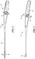
- FIG. 7Another distal treatment assembly portion of a medical device or catheter 42 is depicted in FIG. 7 , which has a distal electrode array 44 with a plurality of electrodes 46 coupled to the array 44.
- the distal electrode array 44may be manipulated to define a substantially linear, helical, or circular configuration, such that linear or substantially circumferential ablation lesion may be created during an ablation procedure.
- the distal treatment assembly 16 of medical device 42may be navigated through the vasculature toward a desired area of treatment, for example, the pulmonary vein. (Step S100).
- the treatment assemblymay then be manipulated to a desired geometric configuration (Step S102).
- the medical device 42may include the electrode array 44, the electrode array 44 being manipulatable to define a substantially linear, helical, or circular configuration.
- the electrode array 44includes ten electrodes 46 spaced a predetermined distance away from each on the array 44.
- Electrodes 2-9are disposed between electrodes 1-10, electrode 2 being adjacent electrode 1 and electrode 9 being adjacent electrode 10, and so on. In particular, when the electrode array 44 defines a substantially circular configuration shown in FIG. 7 , electrodes 1 and 10 may be substantially radially adjacent each other along the electrode array 44.
- an impedance of a pair of the electrodes on the array 44 and/or a pair of electrodes including one electrode on the array 44 and an indifferent or reference electrode (not shown) positioned on the surface of the patient's bodymay be measured (S104).
- the impedance of electrodes 1 and 10, or 2 and 9, or so on, or every electrode 46 on the array 44, or an electrode 46 and indifferent electrodemay be measured and calculated based on the duty cycle and a preselected power supplied by the control unit 10.
- the duty cycleis the voltage.
- the measured impedancemay then be calculated by squaring the voltage and dividing that value by the measured average power.
- the measured powermay range from between approximately 0-10W, but may be any power.
- the measured powermay fluctuate as bubbles are either released or formed on the surface of the electrode 46.
- bubbles on the electrodes 46may act to insulate the target tissue from the thermal energy transmitted to the tissue, and as a result, the power of the medical device may be automatically increased to increase the amount of energy transmitted to the tissue.
- variations in power and the temperature of the electrodes 46 and/or target tissuemay be attributed to bubble release or formation.
- the duty cyclemay be divided by the preset number of fields, for example, 255, to arrive at the percentage of the duty cycle rather than a binary value.
- the impedancemay be measured across all the electrodes 46, some of the electrodes 46, or particular pairs of electrodes depending on the particular geometric configuration defined for the particular ablation treatment.
- Radiofrequency ablation energymay be transmitted between two or more of the electrodes 46 on the array 44, and/or between the electrodes 46 and a reference electrode, or between an electrode on the array 44 and an electrode on another medical device (not shown) for a predetermined period of time at the preselected power (S106).
- radiofrequency ablation energymay be transmitted between electrodes 1 and 10, and/or 2 and 9, and so on, in unipolar, 1:1, 2:1, 4:1, and/or bipolar energy modes.
- the impedance in Step S104may be measured before, during, and/or after radiofrequency ablation energy is transmitted between the electrodes 46.
- the measured impedancemay be compared against a minimum measured impedance value to determine if microbubbles are formed on or proximate the electrodes 46 and are interfering with the pair of electrodes.
- the ramp-up timean analysis of the ramp-up time on over 4000 ablations was completed. As the temperature reaches a preprogrammed temperature set point, or the power reaches the maximum power, the derivative of the power slows down and eventually crosses zero as seen in the plot in FIG. 9 .
- the time to the derivative ⁇ 0.3 Watts/ secondis used as a threshold to determine when the ramp up phase is completed. For example, as shown in FIG. 10 , the median value for the ramp-up time is 7 seconds and the quartiles are at 6 and 9 seconds.
- microbubblesmay form on the surface of the electrodes 46 causing the measured impedance to rise above a minimum measured impedance.
- the measured impedancewhich may fluctuate over time as the target tissue is ablated.
- the measured minimum impedancemay decrease overtime.
- microbubblesmay begin to form or may be instantaneously released, causing the measured impedance to raise from a measured impedance value for a particular energy mode.
- the impedance at any one of the electrodes 46 or electrode pairs, for example, in electrodes 1 and 10is measured to determine if the measured impedance is above the minimum measured impedance value for the particular energy mode by a predetermined value or percentage (Step 108).
- the measured impedancesdecreases over a period of time as the electrodes 1 and 10 are manipulated and are positioned close to each other. As bubbles are released from surface of electrodes 1 and at approximately 50 seconds, the measured impedance rises sharply, in contrast to bubble formation which occurs over a longer period of time.
- Step 110a predetermined percentage threshold
- the flow of radiofrequency energy to the particular electrode 46 and/or electrode pairmay be selectively terminated (Step 112) while the other electrodes 46 in the array 44 may continue to transmit radiofrequency energy.
- the control unit 10may be operate to generate an alert (Step 114), such as in indicator on the displace, to indicate that microbubbles have either or both been formed on the surface of the electrodes 46 or released from a portion or proximate the electrodes 46 on the array 44.
- the measured impedance from an electrode 46 to a reference electrodemay be measured independently from the measured impedance between two electrodes 46 on the array 44.
- the measured impedance values shown in FIG. 11are combined impedances from both bipolar and unipolar mode measurements.
- the control unit 10may be operable to separate the impedance measured from unipolar and bipolar mode such that impedance changes owing to bubble formation or release may be attributed to a particular energy ablation mode.
- the minimum measured impedancemay be a dynamic value or a static value. For example, as shown in FIG. 11 , the minimum measured impedance, which may be the lowest measured impedance over time, decrease as the measured impedance decreases. Alternatively, a static minimum impedance threshold may be selected.
- the transmission of radiofrequencymay be terminated to the entire electrode array 44 when the measured impedance rises above the predetermined percentage value.
- the impedance rise thresholdof 20%
- 8.3% of ablation procedureshad at least one instance of an electrode turning off due to an impedance rise.
- this percentagedecreases to 1.3% of ablations.
- the microbubble detection algorithminfrequently results in the ablation procedure being affected as the result of microbubble formation at the exemplary percentage thresholds.
- the control unit 10may be programmed to perform the various operations and calculate the measured impedances as discussed above. Specifically, the control unit 10 may automatically terminate to the flow of radiofrequency energy to the electrodes 46 or electrode pairs with measured impedance rise above the predetermined percentage threshold and above a power threshold. Alternatively, the control unit 10 may display a visual warning or emit and audio warning when the measured impedance rises above the percentage threshold such that the operator of the control unit 10 may manually terminate the flow of radio frequency energy to the affected electrodes 46.
- a distal treatment assemblybeing configured to define a substantially circular geometric configuration, it is contemplated that the method and system described herein may be used with any configuration of electrodes and distal assemblies in which a shot circuit may occur.
Landscapes
- Health & Medical Sciences (AREA)
- Surgery (AREA)
- Engineering & Computer Science (AREA)
- Life Sciences & Earth Sciences (AREA)
- Biomedical Technology (AREA)
- Otolaryngology (AREA)
- Nuclear Medicine, Radiotherapy & Molecular Imaging (AREA)
- Plasma & Fusion (AREA)
- Physics & Mathematics (AREA)
- Heart & Thoracic Surgery (AREA)
- Medical Informatics (AREA)
- Molecular Biology (AREA)
- Animal Behavior & Ethology (AREA)
- General Health & Medical Sciences (AREA)
- Public Health (AREA)
- Veterinary Medicine (AREA)
- Surgical Instruments (AREA)
Description
- The present invention relates to a system for detecting microbubbles during an ablation procedure.
- Current radiofrequency ablation ("RF") devices are constructed in a variety of configurations to target specific maladies and to provide for specific treatment protocols. In particular, many RF ablation devices have one or more treatment regions in which multiple treatment electrodes are disposed and are torqueable, or otherwise manipulatable, into a variety of different geometric configurations to treat particular cardiovascular tissues. For example, treatment electrodes may be coupled to an array or a carrier assembly manipulatable to define substantially linear, helical, and circular configurations depending on the desired treatment to be performed. In such multi-electrode configurations, each adjacent electrode may be spaced a distance away, whether longitudinal or radial, such that that bipolar or unipolar radiofrequency energy may be transmitted between the electrodes to treat the tissue.
- Because the treatment electrodes may be manipulated into a variety of different positions, adjacent electrodes may be unintentionally positioned too close to one another such during transmission of radiofrequency energy, microbubbles may be formed around or on the electrodes. For example, when the electrode array is torqued to define a substantially circular configuration, when a distal electrode in the array is torqued and manipulated toward a proximal electrode in the array to define a circle, depending on the skill of the surgeon, the array may be over-manipulated such that two or more electrodes may be sufficiently close to one another to cause bubble formation, but not a short circuit between the electrodes. The presence of a high current density between the closely spaced electrodes causes overheating and production of large volume of bubbles surrounding the electrodes. Current methods of detecting short circuits in electrosurgical devices do not provide any method or mechanism for detecting dangerous bubble formation.
- United States Patent specification no.
US - A - 2011/144524 discloses a system for displaying characteristics of target tissue during an ablation procedure that includes an electronic control unit (ECU) configured to receive data regarding electrical properties of the target tissue for a time period. The ECU is also configured to determine a value responsive to the data and indicative of at least one of a predicted depth of a lesion in the target tissue, a predicted temperature of the target tissue, and a likelihood of steam pop of the target tissue for the time period. The system further includes a display device operatively connected to the ECU. The display device is configured to receive the value and display a visual representation indicative of at least one of a predicted depth of a lesion in the target tissue, a predicted temperature of the target tissue, and a likelihood of steam pop of the target tissue for the time period. - United States Patent specification no.
US - A - 2009/275827 discloses a method and system for assessing proximity between an electrode and tissue. The system includes an electronic control unit (ECU). The ECU is configured to acquire values for first and second components of a complex impedance between the electrode and the tissue, and to calculate an electrical coupling index (ECI) responsive to the first and second values. The ECU is further configured to process the ECI to determine the proximity of the electrode to the tissue. The ECU may be configured to calculate an electrical coupling index rate (ECIR) based on the calculated ECI and information relating to the change in location of the electrode, and to assess proximity based on the ECIR. Alternatively, the ECU may be configured to assess the proximity using the calculated ECI, as opposed to the ECIR. - United States Patent specification no.
US - A - 2005/283074 discloses that during a tissue ablation procedure, bubble generation is identified or detected. The ultrasound imaging is optimized to better detect generation of bubbles for more refined visualization and control of the ablation procedure. The generation of bubbles may alternatively or additionally be quantified to assist in control and/or diagnosis during an ablation procedure. Signals are generated based on the detection of a change in bubble characteristics. For example, the detection oftype 2 ortype 1 bubble generation is used to generate audio or visual warning signals. As another example, detection oftype 1 ortype 2 bubbles triggers generation of a control signal for increasing, decreasing or terminating the ablation energy. The generation of the control signal is performed automatically rather than relying on user visualization and reaction. - Accordingly, what is needed is a method of a microbubble detection that facilitates the on-off operation of individual electrodes in an electrode array that is specific to a particular energy delivery mode.
- According to an aspect of the present invention, there is provided a medical system as specified in
claim 1. According to another aspect of the present invention, there is provided a medical system as specified in any of claims 2 - 7. - The present invention advantageously provides a system for detecting microbubble formation during a radiofrequency ablation procedure. The method includes measuring an impedance of a pair of electrodes, at least one electrode in the pair of electrodes being coupled to a treatment assembly of a medical device. Radiofrequency ablation energy is transmitted between the pair of electrodes. The transmission of radiofrequency ablation energy between the pair of electrodes is terminated when after a predetermined period of time the measured impedance in either of the electrodes in the pair of electrodes is a predetermined percentage above a measured minimum impedance and a measured power is above a predetermined power threshold. An alert is generated indicating at least one of the formation and release of microbubbles proximate the pair of electrodes.
- In another aspect the system includes a medical device having a treatment assembly, the treatment assembly having a plurality of electrode pairs, the treatment assembly being manipulatable to define a substantially circular geometric configuration. A control unit is included and operable to measure an impedance of a first pair of the plurality of electrode pairs; transmit radio frequency ablation energy between the plurality of electrode pairs; and terminate the transmission of radio frequency ablation energy between the pair of electrodes when after a predetermined period of time the measured impedance in either of the electrodes in the pair of electrodes is a predetermined percentage above a measured minimum impedance and a measured power is above a predetermined power threshold. The control unit is further operable to generate an alert indicating at least one of the formation and release of microbubbles proximate the pair of electrodes.
- In yet another aspect not being part of the invention the method includes positioning an electrode array of a medical device proximate a tissue to be treated, the electrode array defining a proximal end and distal end and having a plurality of electrode pairs spanning from the proximal end to the distal end. The electrode array is manipulated to define a substantially circular geometric configuration. An impedance of a first pair of the plurality of electrode pairs is measured, the first pair of the plurality of electrode pairs including the most proximal electrode in the electrode array and the most distal electrode in the electrode array. Radiofrequency ablation energy is transmitted between the plurality of electrode pairs. The transmission of radiofrequency ablation energy between the first pair of the plurality of electrodes is terminated when after a predetermined period of time the measured impedance in either of the electrodes in the first pair of the plurality of electrodes is a predetermined percentage above a measured minimum impedance and a measured power is above a predetermined power threshold. An alert is generated indicating at least one of the formation and release of microbubbles proximate the pair of electrodes.
- A more complete understanding of the present invention, and the attendant advantages and features thereof, will be more readily understood by reference to the following detailed description when considered in conjunction with the accompanying drawings wherein:
FIG. 1 is a perspective view of an exemplary control unit constructed in accordance with the principles of the present invention;FIG. 2 is a side view of an exemplary medical device constructed in accordance with the principles of the present invention;FIG. 3 is a side view of another exemplary medical device constructed in accordance with the principles of the present invention;FIG. 4 is a perspective view of an exemplary treatment assembly of a medical device constructed in accordance with the principles of the present invention;FIG. 5 is a front view of the treatment assembly shown inFIG. 4 ;FIG. 6 is a perspective view of the treatment assembly of the medical device shown inFIG. 3 ;FIG. 7 is a perspective view of another exemplary treatment assembly of a medical device constructed in accordance with the principles of the present invention;FIG. 8 is a flow chart illustrating an exemplary method of detecting microbubble formation on electrodes;FIG. 9 is a graph showing the measured power over time and the derivative the power with respect to time to determine the ramp-up times;FIG. 10 is a box and whisker plot showing the median time to power plateau in 4144 ablation data sets, per electrode;FIG. 11 is graph showing an exemplary ablation procedure withelectrodes FIG. 12 is a table showing the percentage of ablations in which a percentage of impedance rise was measured in the electrodes.- Referring now to the drawings in which like reference designators refer to like elements, there is shown in
FIG. 1 an exemplary embodiment of a control unit such as for example an RF generator constructed in accordance with the principles of the present invention, designated generally as 10. Of note, the device components have been represented where appropriate by conventional symbols in the drawings, showing only those specific details that are pertinent to understanding the embodiments of the present invention so as not to obscure the disclosure with details that will be readily apparent to those of ordinary skill in the art having the benefit of the description herein. Moreover, while certain embodiments or figures described herein may illustrate features not expressly indicated on other figures or embodiments, it is understood that the features and components of the system and devices disclosed herein may be included in a variety of different combinations or configurations without departing from the scope and spirit of the invention. - The
control unit 10 may generally include a display or monitor, operating controls, and couplings for connection to one or more medical devices, one or more patient return or "indifferent" electrodes, an ECG, a power cable, and/or other operating equipment. Thecontrol unit 10 may have electronic circuitry to produce the desired ablation energy, to deliver it to the ablation elements of a medical device, to obtain feedback information or parameters from other sensors, and to operate, adjust, modulate or cease providing the ablation energy during a medical treatment of a patient, as well as to display or otherwise inform the physician. - Generally, the
control unit 10 may be operated in various modes which may be selected by the physician. For example, ablation energy may be supplied to one or more ablation elements, for example electrodes, in a bipolar mode, a unipolar mode, or a combination bipolar and unipolar mode. A unipolar mode of operation involves delivering energy between one or more ablation elements on a medical device and one or more patient return or reference electrodes touching the skin of the patient or positioned beneath the patient, such as a back plate. A bipolar mode of operation involves delivering energy between at least two electrodes on a medical device. A combination mode of operation involves delivering energy in both bipolar and unipolar modes simultaneously and/or intermittently. When in a combination mode of operation, it may be possible to select various ratios of activity or ablation energy among the bipolar and unipolar modes, including for example ratios such as 1:1, 2:1, or 4:1 (bipolar:unipolar). For example, an energy mode ratio of 4:1 means that four times more bipolar energy is transmitted between a pair of electrodes compared to unipolar energy transmitted. - The medical devices coupled to the
control unit 10 may be catheters or surgical probes, including for example an electrophysiology catheter having diagnostic and/or treatment components positionable at or near a target tissue region. For example, themedical device 12 illustrated inFIG. 2 may have a shape and dimensions to reach various treatments sites, such as intraluminal access to vascular anatomy, including for example transseptal access to the left atrium of a patient's heart for subsequent treatment or ablation. Themedical device 12 may generally define an elongated,flexible catheter body 14 having adistal treatment assembly 16, as well as ahandle assembly 18 at or near a proximal end of the catheter body. Thedistal treatment assembly 16 may, for example, include one or more ablation elements such aselectrodes 20, each of which may be electrically coupled to thecontrol unit 10. Thedistal treatment assembly 16 of themedical device 12 may have a linear shape, with a plurality of ablation elements orelectrodes 20. Thecatheter body 14 may be both flexible and resilient, with sufficient column strength facilitating steady contact with tissue, which improves signal fidelity in diagnosing contacted tissue as well as improve therapeutic thermal exchange between the device and contacted tissue. Theproximal handle assembly 18 has arotational actuator 22 for manipulating, bending, steering and/or reshaping thedistal treatment assembly 16 into various desired shapes, curves, etc. FIGS. 3-5 show a medical device orablation catheter 24 with a catheter shaft and adistal treatment assembly 26 with compound carrier arms or electrode arrays which may be resilient, so that in a deployed configuration theelectrodes 28 have a generally planar arrangement. Similar to themedical device 12 ofFIG. 2 , thedistal treatment assembly 26 may be used for bipolar ablation, unipolar ablation, or a combination thereof. Aproximal handle 30 has arotational actuator 32 for manipulating a distal portion of the ablation catheter, and alinear actuator 34. Thelinear actuator 32 can advance thedistal treatment assembly 26 distally beyond the catheter shaft, and retract thedistal treatment assembly 26 proximally inside the catheter shaft. When thedistal treatment assembly 26 is advanced distally, it may resiliently expand from a compressed arrangement inside the catheter shaft to the deployed arrangement shown inFIGS. 4 and 5 .FIG. 6 shows a distal treatment assembly portion of a medical device orcatheter 36 which has a resilient framework ofcarrier arms 38, in which theelectrodes 40 have a proximally-directed configuration, which may for example be used for transseptal treatments of a patient's heart. Another distal treatment assembly portion of a medical device orcatheter 42 is depicted inFIG. 7 , which has a distal electrode array 44 with a plurality ofelectrodes 46 coupled to the array 44. The distal electrode array 44 may be manipulated to define a substantially linear, helical, or circular configuration, such that linear or substantially circumferential ablation lesion may be created during an ablation procedure.- Now referring to
FIG. 8 in which exemplary method of detecting a microbubble formation on a pair of electrodes. Thedistal treatment assembly 16 ofmedical device 42, or any electrosurgical catheter, such as the medical devices discussed above, may be navigated through the vasculature toward a desired area of treatment, for example, the pulmonary vein. (Step S100). The treatment assembly may then be manipulated to a desired geometric configuration (Step S102). For example, themedical device 42 may include the electrode array 44, the electrode array 44 being manipulatable to define a substantially linear, helical, or circular configuration. In an exemplary configuration, the electrode array 44 includes tenelectrodes 46 spaced a predetermined distance away from each on the array 44. Theelectrode 46 proximate the proximal end of the electrode array 44 when configured into a substantially linear configuration is referred to herein as electrode "1." Theelectrode 46 proximate the distal end of the electrode array 44 when configured into a substantially linear configuration is referred to herein as electrode "10." Electrodes 2-9 are disposed between electrodes 1-10,electrode 2 beingadjacent electrode 1 andelectrode 9 beingadjacent electrode 10, and so on. In particular, when the electrode array 44 defines a substantially circular configuration shown inFIG. 7 ,electrodes - Continuing to refer to
FIG. 8 , an impedance of a pair of the electrodes on the array 44 and/or a pair of electrodes including one electrode on the array 44 and an indifferent or reference electrode (not shown) positioned on the surface of the patient's body, may be measured (S104). In particular, the impedance ofelectrodes electrode 46 on the array 44, or anelectrode 46 and indifferent electrode, may be measured and calculated based on the duty cycle and a preselected power supplied by thecontrol unit 10. In an exemplary calculation, the duty cycle is the voltage. The measured impedance may then be calculated by squaring the voltage and dividing that value by the measured average power. In an exemplary configuration, the measured power may range from between approximately 0-10W, but may be any power. The measured power, however, may fluctuate as bubbles are either released or formed on the surface of theelectrode 46. For example, bubbles on theelectrodes 46 may act to insulate the target tissue from the thermal energy transmitted to the tissue, and as a result, the power of the medical device may be automatically increased to increase the amount of energy transmitted to the tissue. Thus, it is contemplated that variations in power and the temperature of theelectrodes 46 and/or target tissue may be attributed to bubble release or formation. - To calculate the voltage the duty cycle may be divided by the preset number of fields, for example, 255, to arrive at the percentage of the duty cycle rather than a binary value. The impedance may be measured across all the
electrodes 46, some of theelectrodes 46, or particular pairs of electrodes depending on the particular geometric configuration defined for the particular ablation treatment. - Radiofrequency ablation energy may be transmitted between two or more of the
electrodes 46 on the array 44, and/or between theelectrodes 46 and a reference electrode, or between an electrode on the array 44 and an electrode on another medical device (not shown) for a predetermined period of time at the preselected power (S106). For example, radiofrequency ablation energy may be transmitted betweenelectrodes electrodes 46. After a predetermined period of ablation time, referred to herein as the ramp-up time, the measured impedance may be compared against a minimum measured impedance value to determine if microbubbles are formed on or proximate theelectrodes 46 and are interfering with the pair of electrodes. - In particular, to determine the ramp-up time, an analysis of the ramp-up time on over 4000 ablations was completed. As the temperature reaches a preprogrammed temperature set point, or the power reaches the maximum power, the derivative of the power slows down and eventually crosses zero as seen in the plot in
FIG. 9 . The time to the derivative < 0.3 Watts/ second is used as a threshold to determine when the ramp up phase is completed. For example, as shown inFIG. 10 , the median value for the ramp-up time is 7 seconds and the quartiles are at 6 and 9 seconds. - When the
electrodes 46 are close together but not touching, microbubbles may form on the surface of theelectrodes 46 causing the measured impedance to rise above a minimum measured impedance. In particular, the measured impedance, which may fluctuate over time as the target tissue is ablated. Thus the measured minimum impedance may decrease overtime. However, because the electrodes are close together, microbubbles may begin to form or may be instantaneously released, causing the measured impedance to raise from a measured impedance value for a particular energy mode. - Now referring to
FIG. 11 , the impedance at any one of theelectrodes 46 or electrode pairs, for example, inelectrodes FIG. 11 in which radiofrequency ablation energy is transmitted betweenelectrodes electrodes electrodes 1 and at approximately 50 seconds, the measured impedance rises sharply, in contrast to bubble formation which occurs over a longer period of time. When the measured impedance rises above a predetermined percentage threshold, for example, 20%, 35%, or any percentage above the minimum measured impedance, or above the present measured impedance, and the measured power is above a predetermined power threshold (Step 110), for example, 2.5 Watts, then the flow of radiofrequency energy to theparticular electrode 46 and/or electrode pair may be selectively terminated (Step 112) while theother electrodes 46 in the array 44 may continue to transmit radiofrequency energy. Should the flow of radiofrequency be terminated, thecontrol unit 10 may be operate to generate an alert (Step 114), such as in indicator on the displace, to indicate that microbubbles have either or both been formed on the surface of theelectrodes 46 or released from a portion or proximate theelectrodes 46 on the array 44. It is further contemplated the measured impedance from anelectrode 46 to a reference electrode may be measured independently from the measured impedance between twoelectrodes 46 on the array 44. In particular the measured impedance values shown inFIG. 11 are combined impedances from both bipolar and unipolar mode measurements. However, thecontrol unit 10 may be operable to separate the impedance measured from unipolar and bipolar mode such that impedance changes owing to bubble formation or release may be attributed to a particular energy ablation mode. - The minimum measured impedance may be a dynamic value or a static value. For example, as shown in
FIG. 11 , the minimum measured impedance, which may be the lowest measured impedance over time, decrease as the measured impedance decreases. Alternatively, a static minimum impedance threshold may be selected. - Alternatively, the transmission of radiofrequency may be terminated to the entire electrode array 44 when the measured impedance rises above the predetermined percentage value. In an exemplary embodiment shown in
FIG. 12 , when measured impedance rises to approximately 100 ohms from a measured value of approximately 85 ohms,electrodes FIG. 12 , at a percentage impedance rise threshold of 20%, 8.3% of ablation procedures had at least one instance of an electrode turning off due to an impedance rise. With a threshold of 35%, this percentage decreases to 1.3% of ablations. As such, the microbubble detection algorithm infrequently results in the ablation procedure being affected as the result of microbubble formation at the exemplary percentage thresholds. - The
control unit 10 may be programmed to perform the various operations and calculate the measured impedances as discussed above. Specifically, thecontrol unit 10 may automatically terminate to the flow of radiofrequency energy to theelectrodes 46 or electrode pairs with measured impedance rise above the predetermined percentage threshold and above a power threshold. Alternatively, thecontrol unit 10 may display a visual warning or emit and audio warning when the measured impedance rises above the percentage threshold such that the operator of thecontrol unit 10 may manually terminate the flow of radio frequency energy to theaffected electrodes 46. Although the method and system described above is described with respect to a distal treatment assembly being configured to define a substantially circular geometric configuration, it is contemplated that the method and system described herein may be used with any configuration of electrodes and distal assemblies in which a shot circuit may occur. - It will be appreciated by persons skilled in the art that the present invention is not limited to what has been particularly shown and described herein above. In addition, unless mention was made above to the contrary, it should be noted that all of the accompanying drawings are not to scale. A variety of modifications and variations are possible in light of the above teachings without departing from the scope of the invention, which is limited only by the following claims.
Claims (7)
- A medical system, comprising:a medical device (42) having a treatment assembly, the treatment assembly comprising a distal electrode array (44) with a plurality of electrodes coupled to the array (44), the array (44) being manipulatable to define an open circle circular geometric configuration;a control unit (10) operable to:measure an impedance of a first pair of the plurality of electrode pairs (46);transmit radiofrequency ablation energy between the plurality of electrode pairs (46);selectively terminate the transmission of radiofrequency ablation energy from at least one pair of electrode pairs (46) when, after a period of time between six seconds and nine seconds from the beginning of transmission of the radiofrequency ablation energy:the measured impedance in either of the electrodes (46) in the first pair of electrodes is a predetermined percentage above a measured minimum impedance; anda measured power is above a predetermined power threshold; and generate an alert indicating at least one of the formation and release of microbubbles proximate the first pair of electrodes (46), the termination of the transmission of radiofrequency ablation energy between the first pair of the plurality of electrode pairs (46) is independent of the transmission of radiofrequency ablation energy between electrode pairs (46) on the treatment assembly other than the first pair of the plurality of electrode pairs (46).
- The system of Claim 1, wherein the predetermined time period is approximately 7 seconds.
- The system of Claim 1, wherein the control unit is further operable to transmit radiofrequency energy between at least one of the electrodes in the plurality of electrode pairs and a reference electrode.
- The system of Claim 1, wherein the control unit is further operable to correlate a rise in the measured impedance above a predetermined percentage above the measured minimum impedance to a determination of a presence of bubbles proximate the plurality of electrode pairs.
- The system of Claim 1, wherein the predetermined percentage is approximately 20%.
- The system of Claim 1, wherein the predetermined percentage is approximately 35%.
- The system of Claim 1, wherein the predetermined power threshold approximately 2.5 Watts.
Applications Claiming Priority (3)
| Application Number | Priority Date | Filing Date | Title |
|---|---|---|---|
| US13/456,592US9060778B2 (en) | 2012-04-26 | 2012-04-26 | Intermittent short circuit detection on a multi-electrode catheter |
| US13/460,864US9216050B2 (en) | 2012-05-01 | 2012-05-01 | Detection of microbubble formation during catheter ablation |
| PCT/US2013/035882WO2013162883A1 (en) | 2012-04-26 | 2013-04-10 | Detection of microbubble formation during an ablation procedure |
Publications (2)
| Publication Number | Publication Date |
|---|---|
| EP2840997A1 EP2840997A1 (en) | 2015-03-04 |
| EP2840997B1true EP2840997B1 (en) | 2017-06-28 |
Family
ID=48444556
Family Applications (1)
| Application Number | Title | Priority Date | Filing Date |
|---|---|---|---|
| EP13722876.3AActiveEP2840997B1 (en) | 2012-04-26 | 2013-04-10 | Detection of microbubble formation during an ablation procedure |
Country Status (3)
| Country | Link |
|---|---|
| EP (1) | EP2840997B1 (en) |
| CN (1) | CN104582620B (en) |
| WO (1) | WO2013162883A1 (en) |
Families Citing this family (5)
| Publication number | Priority date | Publication date | Assignee | Title |
|---|---|---|---|---|
| US11540881B2 (en)* | 2018-08-23 | 2023-01-03 | Boston Scientific Scimed, Inc. | Microwave ablation probe with radiofrequency impedance sensing |
| US11737821B2 (en)* | 2019-07-30 | 2023-08-29 | Biosense Webster (Israel) Ltd. | Bubble detector on proximal end of catheter with fail-safe mechanism |
| CN111214288B (en)* | 2019-12-24 | 2025-06-17 | 杭州诺诚医疗器械有限公司 | Radiofrequency ablation power output control method and device, and radiofrequency ablation system |
| CN117679147A (en)* | 2022-09-02 | 2024-03-12 | 杭州堃博生物科技有限公司 | Method and system for automatically adjusting power |
| CN119423952A (en)* | 2023-07-31 | 2025-02-14 | 上海鸿电医疗科技有限公司 | Radiofrequency ablation catheter and radiofrequency ablation device |
Family Cites Families (10)
| Publication number | Priority date | Publication date | Assignee | Title |
|---|---|---|---|---|
| US6132426A (en)* | 1998-05-05 | 2000-10-17 | Daig Corporation | Temperature and current limited ablation catheter |
| US20050283074A1 (en)* | 2004-06-22 | 2005-12-22 | Siemens Medical Solutions Usa, Inc. | Ultrasound feedback for tissue ablation procedures |
| US10362959B2 (en)* | 2005-12-06 | 2019-07-30 | St. Jude Medical, Atrial Fibrillation Division, Inc. | System and method for assessing the proximity of an electrode to tissue in a body |
| BRPI0621017A2 (en)* | 2005-12-06 | 2011-11-29 | St Jude Medical Atrial Fibrill Div | tissue ablation electrode junction evaluation |
| US9492226B2 (en)* | 2005-12-06 | 2016-11-15 | St. Jude Medical, Atrial Fibrillation Division, Inc. | Graphical user interface for real-time RF lesion depth display |
| US8147485B2 (en)* | 2006-01-24 | 2012-04-03 | Covidien Ag | System and method for tissue sealing |
| US20100168571A1 (en)* | 2006-08-11 | 2010-07-01 | Koninklijke Philips Electronics N.V. | Image-based power feedback for optimal ultrasound imaging or radio frequency tissue ablation |
| US8641704B2 (en)* | 2007-05-11 | 2014-02-04 | Medtronic Ablation Frontiers Llc | Ablation therapy system and method for treating continuous atrial fibrillation |
| US8262652B2 (en)* | 2009-01-12 | 2012-09-11 | Tyco Healthcare Group Lp | Imaginary impedance process monitoring and intelligent shut-off |
| US9820803B2 (en)* | 2010-04-28 | 2017-11-21 | Medtronic, Inc. | Subxiphoid connective lesion ablation system and method |
- 2013
- 2013-04-10CNCN201380022108.4Apatent/CN104582620B/enactiveActive
- 2013-04-10EPEP13722876.3Apatent/EP2840997B1/enactiveActive
- 2013-04-10WOPCT/US2013/035882patent/WO2013162883A1/enactiveApplication Filing
Also Published As
| Publication number | Publication date |
|---|---|
| EP2840997A1 (en) | 2015-03-04 |
| CN104582620A (en) | 2015-04-29 |
| WO2013162883A1 (en) | 2013-10-31 |
| CN104582620B (en) | 2017-07-21 |
Similar Documents
| Publication | Publication Date | Title |
|---|---|---|
| US9216050B2 (en) | Detection of microbubble formation during catheter ablation | |
| US9060778B2 (en) | Intermittent short circuit detection on a multi-electrode catheter | |
| CN112451081B (en) | Dynamic ablation and sensing of contact based on segmented electrodes | |
| US20230414279A1 (en) | Ablation catheters and related systems and methods | |
| EP2840996B1 (en) | System for detecting tissue contact during ablation | |
| US9750570B2 (en) | Systems and methods for detecting tissue contact during ablation | |
| US9095350B2 (en) | Impedance detection of venous placement of multi-electrode catheters | |
| JP2021090749A (en) | Catheter with multiple sensing electrodes used as ablation electrode | |
| US20110190755A1 (en) | Patient return electrode detection for ablation system | |
| CN114502067A (en) | Lesion assessment using peak-to-peak impedance magnitude measurements | |
| JP2019013759A (en) | Temperature-controlled short-time ablation using multiple electrodes | |
| US20130138097A1 (en) | System and method to detect patient return electrode connection in an rf ablation system | |
| WO2016168778A1 (en) | Tissue diagnosis and treatment using electrodes and mini-electrodes | |
| EP3143957B1 (en) | Ablation current measurement | |
| US10575900B2 (en) | Tissue contact sensing vector | |
| EP2840997B1 (en) | Detection of microbubble formation during an ablation procedure | |
| AU2016277713A1 (en) | Temperature controlled short duration ablation | |
| US20190350490A1 (en) | Methods and systems for enhanced mapping of tissue | |
| AU2016277712A1 (en) | Temperature controlled short duration ablation | |
| AU2016277710A1 (en) | Temperature controlled short duration ablation | |
| CN115886980A (en) | Phrenic Nerve Warning | |
| JP2024002964A (en) | Graphical contact quality indicator for balloon catheter navigation | |
| US20250213295A1 (en) | Electroporation ablation from tissue-contacting electrodes |
Legal Events
| Date | Code | Title | Description |
|---|---|---|---|
| PUAI | Public reference made under article 153(3) epc to a published international application that has entered the european phase | Free format text:ORIGINAL CODE: 0009012 | |
| 17P | Request for examination filed | Effective date:20141126 | |
| AK | Designated contracting states | Kind code of ref document:A1 Designated state(s):AL AT BE BG CH CY CZ DE DK EE ES FI FR GB GR HR HU IE IS IT LI LT LU LV MC MK MT NL NO PL PT RO RS SE SI SK SM TR | |
| AX | Request for extension of the european patent | Extension state:BA ME | |
| DAX | Request for extension of the european patent (deleted) | ||
| 17Q | First examination report despatched | Effective date:20151214 | |
| GRAP | Despatch of communication of intention to grant a patent | Free format text:ORIGINAL CODE: EPIDOSNIGR1 | |
| STAA | Information on the status of an ep patent application or granted ep patent | Free format text:STATUS: GRANT OF PATENT IS INTENDED | |
| INTG | Intention to grant announced | Effective date:20170127 | |
| GRAS | Grant fee paid | Free format text:ORIGINAL CODE: EPIDOSNIGR3 | |
| GRAA | (expected) grant | Free format text:ORIGINAL CODE: 0009210 | |
| STAA | Information on the status of an ep patent application or granted ep patent | Free format text:STATUS: THE PATENT HAS BEEN GRANTED | |
| AK | Designated contracting states | Kind code of ref document:B1 Designated state(s):AL AT BE BG CH CY CZ DE DK EE ES FI FR GB GR HR HU IE IS IT LI LT LU LV MC MK MT NL NO PL PT RO RS SE SI SK SM TR | |
| REG | Reference to a national code | Ref country code:GB Ref legal event code:FG4D | |
| REG | Reference to a national code | Ref country code:CH Ref legal event code:EP | |
| REG | Reference to a national code | Ref country code:AT Ref legal event code:REF Ref document number:904164 Country of ref document:AT Kind code of ref document:T Effective date:20170715 | |
| REG | Reference to a national code | Ref country code:IE Ref legal event code:FG4D | |
| REG | Reference to a national code | Ref country code:DE Ref legal event code:R096 Ref document number:602013022842 Country of ref document:DE | |
| PG25 | Lapsed in a contracting state [announced via postgrant information from national office to epo] | Ref country code:HR Free format text:LAPSE BECAUSE OF FAILURE TO SUBMIT A TRANSLATION OF THE DESCRIPTION OR TO PAY THE FEE WITHIN THE PRESCRIBED TIME-LIMIT Effective date:20170628 Ref country code:NO Free format text:LAPSE BECAUSE OF FAILURE TO SUBMIT A TRANSLATION OF THE DESCRIPTION OR TO PAY THE FEE WITHIN THE PRESCRIBED TIME-LIMIT Effective date:20170928 Ref country code:GR Free format text:LAPSE BECAUSE OF FAILURE TO SUBMIT A TRANSLATION OF THE DESCRIPTION OR TO PAY THE FEE WITHIN THE PRESCRIBED TIME-LIMIT Effective date:20170929 Ref country code:LT Free format text:LAPSE BECAUSE OF FAILURE TO SUBMIT A TRANSLATION OF THE DESCRIPTION OR TO PAY THE FEE WITHIN THE PRESCRIBED TIME-LIMIT Effective date:20170628 Ref country code:FI Free format text:LAPSE BECAUSE OF FAILURE TO SUBMIT A TRANSLATION OF THE DESCRIPTION OR TO PAY THE FEE WITHIN THE PRESCRIBED TIME-LIMIT Effective date:20170628 | |
| REG | Reference to a national code | Ref country code:NL Ref legal event code:MP Effective date:20170628 | |
| REG | Reference to a national code | Ref country code:LT Ref legal event code:MG4D | |
| REG | Reference to a national code | Ref country code:AT Ref legal event code:MK05 Ref document number:904164 Country of ref document:AT Kind code of ref document:T Effective date:20170628 | |
| PG25 | Lapsed in a contracting state [announced via postgrant information from national office to epo] | Ref country code:RS Free format text:LAPSE BECAUSE OF FAILURE TO SUBMIT A TRANSLATION OF THE DESCRIPTION OR TO PAY THE FEE WITHIN THE PRESCRIBED TIME-LIMIT Effective date:20170628 Ref country code:SE Free format text:LAPSE BECAUSE OF FAILURE TO SUBMIT A TRANSLATION OF THE DESCRIPTION OR TO PAY THE FEE WITHIN THE PRESCRIBED TIME-LIMIT Effective date:20170628 Ref country code:LV Free format text:LAPSE BECAUSE OF FAILURE TO SUBMIT A TRANSLATION OF THE DESCRIPTION OR TO PAY THE FEE WITHIN THE PRESCRIBED TIME-LIMIT Effective date:20170628 Ref country code:BG Free format text:LAPSE BECAUSE OF FAILURE TO SUBMIT A TRANSLATION OF THE DESCRIPTION OR TO PAY THE FEE WITHIN THE PRESCRIBED TIME-LIMIT Effective date:20170928 Ref country code:NL Free format text:LAPSE BECAUSE OF FAILURE TO SUBMIT A TRANSLATION OF THE DESCRIPTION OR TO PAY THE FEE WITHIN THE PRESCRIBED TIME-LIMIT Effective date:20170628 | |
| PG25 | Lapsed in a contracting state [announced via postgrant information from national office to epo] | Ref country code:AT Free format text:LAPSE BECAUSE OF FAILURE TO SUBMIT A TRANSLATION OF THE DESCRIPTION OR TO PAY THE FEE WITHIN THE PRESCRIBED TIME-LIMIT Effective date:20170628 Ref country code:EE Free format text:LAPSE BECAUSE OF FAILURE TO SUBMIT A TRANSLATION OF THE DESCRIPTION OR TO PAY THE FEE WITHIN THE PRESCRIBED TIME-LIMIT Effective date:20170628 Ref country code:CZ Free format text:LAPSE BECAUSE OF FAILURE TO SUBMIT A TRANSLATION OF THE DESCRIPTION OR TO PAY THE FEE WITHIN THE PRESCRIBED TIME-LIMIT Effective date:20170628 Ref country code:RO Free format text:LAPSE BECAUSE OF FAILURE TO SUBMIT A TRANSLATION OF THE DESCRIPTION OR TO PAY THE FEE WITHIN THE PRESCRIBED TIME-LIMIT Effective date:20170628 Ref country code:SK Free format text:LAPSE BECAUSE OF FAILURE TO SUBMIT A TRANSLATION OF THE DESCRIPTION OR TO PAY THE FEE WITHIN THE PRESCRIBED TIME-LIMIT Effective date:20170628 | |
| PG25 | Lapsed in a contracting state [announced via postgrant information from national office to epo] | Ref country code:ES Free format text:LAPSE BECAUSE OF FAILURE TO SUBMIT A TRANSLATION OF THE DESCRIPTION OR TO PAY THE FEE WITHIN THE PRESCRIBED TIME-LIMIT Effective date:20170628 Ref country code:SM Free format text:LAPSE BECAUSE OF FAILURE TO SUBMIT A TRANSLATION OF THE DESCRIPTION OR TO PAY THE FEE WITHIN THE PRESCRIBED TIME-LIMIT Effective date:20170628 Ref country code:PL Free format text:LAPSE BECAUSE OF FAILURE TO SUBMIT A TRANSLATION OF THE DESCRIPTION OR TO PAY THE FEE WITHIN THE PRESCRIBED TIME-LIMIT Effective date:20170628 Ref country code:IT Free format text:LAPSE BECAUSE OF FAILURE TO SUBMIT A TRANSLATION OF THE DESCRIPTION OR TO PAY THE FEE WITHIN THE PRESCRIBED TIME-LIMIT Effective date:20170628 Ref country code:IS Free format text:LAPSE BECAUSE OF FAILURE TO SUBMIT A TRANSLATION OF THE DESCRIPTION OR TO PAY THE FEE WITHIN THE PRESCRIBED TIME-LIMIT Effective date:20171028 | |
| REG | Reference to a national code | Ref country code:FR Ref legal event code:PLFP Year of fee payment:6 | |
| REG | Reference to a national code | Ref country code:DE Ref legal event code:R097 Ref document number:602013022842 Country of ref document:DE | |
| PG25 | Lapsed in a contracting state [announced via postgrant information from national office to epo] | Ref country code:DK Free format text:LAPSE BECAUSE OF FAILURE TO SUBMIT A TRANSLATION OF THE DESCRIPTION OR TO PAY THE FEE WITHIN THE PRESCRIBED TIME-LIMIT Effective date:20170628 | |
| PLBE | No opposition filed within time limit | Free format text:ORIGINAL CODE: 0009261 | |
| 26N | No opposition filed | Effective date:20180329 | |
| PG25 | Lapsed in a contracting state [announced via postgrant information from national office to epo] | Ref country code:SI Free format text:LAPSE BECAUSE OF FAILURE TO SUBMIT A TRANSLATION OF THE DESCRIPTION OR TO PAY THE FEE WITHIN THE PRESCRIBED TIME-LIMIT Effective date:20170628 | |
| PG25 | Lapsed in a contracting state [announced via postgrant information from national office to epo] | Ref country code:MC Free format text:LAPSE BECAUSE OF FAILURE TO SUBMIT A TRANSLATION OF THE DESCRIPTION OR TO PAY THE FEE WITHIN THE PRESCRIBED TIME-LIMIT Effective date:20170628 | |
| REG | Reference to a national code | Ref country code:CH Ref legal event code:PL | |
| REG | Reference to a national code | Ref country code:BE Ref legal event code:MM Effective date:20180430 | |
| GBPC | Gb: european patent ceased through non-payment of renewal fee | Effective date:20180410 | |
| REG | Reference to a national code | Ref country code:IE Ref legal event code:MM4A | |
| PG25 | Lapsed in a contracting state [announced via postgrant information from national office to epo] | Ref country code:LU Free format text:LAPSE BECAUSE OF NON-PAYMENT OF DUE FEES Effective date:20180410 | |
| PG25 | Lapsed in a contracting state [announced via postgrant information from national office to epo] | Ref country code:LI Free format text:LAPSE BECAUSE OF NON-PAYMENT OF DUE FEES Effective date:20180430 Ref country code:CH Free format text:LAPSE BECAUSE OF NON-PAYMENT OF DUE FEES Effective date:20180430 Ref country code:GB Free format text:LAPSE BECAUSE OF NON-PAYMENT OF DUE FEES Effective date:20180410 Ref country code:BE Free format text:LAPSE BECAUSE OF NON-PAYMENT OF DUE FEES Effective date:20180430 | |
| PG25 | Lapsed in a contracting state [announced via postgrant information from national office to epo] | Ref country code:IE Free format text:LAPSE BECAUSE OF NON-PAYMENT OF DUE FEES Effective date:20180410 | |
| PG25 | Lapsed in a contracting state [announced via postgrant information from national office to epo] | Ref country code:MT Free format text:LAPSE BECAUSE OF NON-PAYMENT OF DUE FEES Effective date:20180410 | |
| PG25 | Lapsed in a contracting state [announced via postgrant information from national office to epo] | Ref country code:TR Free format text:LAPSE BECAUSE OF FAILURE TO SUBMIT A TRANSLATION OF THE DESCRIPTION OR TO PAY THE FEE WITHIN THE PRESCRIBED TIME-LIMIT Effective date:20170628 | |
| PG25 | Lapsed in a contracting state [announced via postgrant information from national office to epo] | Ref country code:PT Free format text:LAPSE BECAUSE OF FAILURE TO SUBMIT A TRANSLATION OF THE DESCRIPTION OR TO PAY THE FEE WITHIN THE PRESCRIBED TIME-LIMIT Effective date:20170628 Ref country code:HU Free format text:LAPSE BECAUSE OF FAILURE TO SUBMIT A TRANSLATION OF THE DESCRIPTION OR TO PAY THE FEE WITHIN THE PRESCRIBED TIME-LIMIT; INVALID AB INITIO Effective date:20130410 | |
| PG25 | Lapsed in a contracting state [announced via postgrant information from national office to epo] | Ref country code:CY Free format text:LAPSE BECAUSE OF FAILURE TO SUBMIT A TRANSLATION OF THE DESCRIPTION OR TO PAY THE FEE WITHIN THE PRESCRIBED TIME-LIMIT Effective date:20170628 Ref country code:MK Free format text:LAPSE BECAUSE OF NON-PAYMENT OF DUE FEES Effective date:20170628 | |
| PG25 | Lapsed in a contracting state [announced via postgrant information from national office to epo] | Ref country code:AL Free format text:LAPSE BECAUSE OF FAILURE TO SUBMIT A TRANSLATION OF THE DESCRIPTION OR TO PAY THE FEE WITHIN THE PRESCRIBED TIME-LIMIT Effective date:20170628 | |
| STAA | Information on the status of an ep patent application or granted ep patent | Free format text:STATUS: NO OPPOSITION FILED WITHIN TIME LIMIT | |
| PGFP | Annual fee paid to national office [announced via postgrant information from national office to epo] | Ref country code:FR Payment date:20250319 Year of fee payment:13 | |
| PGFP | Annual fee paid to national office [announced via postgrant information from national office to epo] | Ref country code:DE Payment date:20250319 Year of fee payment:13 |