EP2840805B1 - Dual coil loudspeaker system - Google Patents
Dual coil loudspeaker systemDownload PDFInfo
- Publication number
- EP2840805B1 EP2840805B1EP14172691.9AEP14172691AEP2840805B1EP 2840805 B1EP2840805 B1EP 2840805B1EP 14172691 AEP14172691 AEP 14172691AEP 2840805 B1EP2840805 B1EP 2840805B1
- Authority
- EP
- European Patent Office
- Prior art keywords
- coil
- diaphragm
- loudspeaker system
- dual
- tube
- Prior art date
- Legal status (The legal status is an assumption and is not a legal conclusion. Google has not performed a legal analysis and makes no representation as to the accuracy of the status listed.)
- Not-in-force
Links
- 230000009977dual effectEffects0.000titleclaimsdescription42
- 230000008878couplingEffects0.000claimsdescription8
- 238000010168coupling processMethods0.000claimsdescription8
- 238000005859coupling reactionMethods0.000claimsdescription8
- 239000000463materialSubstances0.000claimsdescription5
- 239000004033plasticSubstances0.000claimsdescription5
- 239000002184metalSubstances0.000claimsdescription4
- 241000239290AraneaeSpecies0.000claimsdescription3
- 239000011152fibreglassSubstances0.000claimsdescription3
- 239000000123paperSubstances0.000claimsdescription3
- 230000005236sound signalEffects0.000description22
- 239000010410layerSubstances0.000description4
- 238000000034methodMethods0.000description4
- 238000013016dampingMethods0.000description3
- 239000004593EpoxySubstances0.000description2
- 239000000853adhesiveSubstances0.000description2
- 230000001070adhesive effectEffects0.000description2
- 239000002131composite materialSubstances0.000description2
- 239000000725suspensionSubstances0.000description2
- 229910000831SteelInorganic materials0.000description1
- 230000003111delayed effectEffects0.000description1
- 238000013461designMethods0.000description1
- 238000011161developmentMethods0.000description1
- 230000018109developmental processEffects0.000description1
- 230000000694effectsEffects0.000description1
- 239000013013elastic materialSubstances0.000description1
- 238000010304firingMethods0.000description1
- 239000011888foilSubstances0.000description1
- 239000000696magnetic materialSubstances0.000description1
- 238000012986modificationMethods0.000description1
- 230000004048modificationEffects0.000description1
- 239000012811non-conductive materialSubstances0.000description1
- 230000035939shockEffects0.000description1
- 239000002356single layerSubstances0.000description1
- 239000010959steelSubstances0.000description1
- 238000012360testing methodMethods0.000description1
Images


Classifications
- H—ELECTRICITY
- H04—ELECTRIC COMMUNICATION TECHNIQUE
- H04R—LOUDSPEAKERS, MICROPHONES, GRAMOPHONE PICK-UPS OR LIKE ACOUSTIC ELECTROMECHANICAL TRANSDUCERS; DEAF-AID SETS; PUBLIC ADDRESS SYSTEMS
- H04R1/00—Details of transducers, loudspeakers or microphones
- H—ELECTRICITY
- H04—ELECTRIC COMMUNICATION TECHNIQUE
- H04R—LOUDSPEAKERS, MICROPHONES, GRAMOPHONE PICK-UPS OR LIKE ACOUSTIC ELECTROMECHANICAL TRANSDUCERS; DEAF-AID SETS; PUBLIC ADDRESS SYSTEMS
- H04R9/00—Transducers of moving-coil, moving-strip, or moving-wire type
- H04R9/02—Details
- H04R9/025—Magnetic circuit
- H—ELECTRICITY
- H04—ELECTRIC COMMUNICATION TECHNIQUE
- H04R—LOUDSPEAKERS, MICROPHONES, GRAMOPHONE PICK-UPS OR LIKE ACOUSTIC ELECTROMECHANICAL TRANSDUCERS; DEAF-AID SETS; PUBLIC ADDRESS SYSTEMS
- H04R2209/00—Details of transducers of the moving-coil, moving-strip, or moving-wire type covered by H04R9/00 but not provided for in any of its subgroups
- H04R2209/041—Voice coil arrangements comprising more than one voice coil unit on the same bobbin
- H—ELECTRICITY
- H04—ELECTRIC COMMUNICATION TECHNIQUE
- H04R—LOUDSPEAKERS, MICROPHONES, GRAMOPHONE PICK-UPS OR LIKE ACOUSTIC ELECTROMECHANICAL TRANSDUCERS; DEAF-AID SETS; PUBLIC ADDRESS SYSTEMS
- H04R2499/00—Aspects covered by H04R or H04S not otherwise provided for in their subgroups
- H04R2499/10—General applications
- H04R2499/13—Acoustic transducers and sound field adaptation in vehicles
- H—ELECTRICITY
- H04—ELECTRIC COMMUNICATION TECHNIQUE
- H04R—LOUDSPEAKERS, MICROPHONES, GRAMOPHONE PICK-UPS OR LIKE ACOUSTIC ELECTROMECHANICAL TRANSDUCERS; DEAF-AID SETS; PUBLIC ADDRESS SYSTEMS
- H04R7/00—Diaphragms for electromechanical transducers; Cones
- H04R7/02—Diaphragms for electromechanical transducers; Cones characterised by the construction
- H04R7/04—Plane diaphragms
- H—ELECTRICITY
- H04—ELECTRIC COMMUNICATION TECHNIQUE
- H04R—LOUDSPEAKERS, MICROPHONES, GRAMOPHONE PICK-UPS OR LIKE ACOUSTIC ELECTROMECHANICAL TRANSDUCERS; DEAF-AID SETS; PUBLIC ADDRESS SYSTEMS
- H04R9/00—Transducers of moving-coil, moving-strip, or moving-wire type
- H04R9/02—Details
- H04R9/04—Construction, mounting, or centering of coil
- H04R9/045—Mounting
Definitions
- the disclosurerelates to loudspeaker systems, and more particularly, to loudspeaker systems driven by amplifiers.
- Speaker systemssuch as the speaker systems mounted on aircraft and other vehicles, include one or more cone speakers powered by one or more amplifiers.
- loudspeaker systemsincorporate flat panel speakers as part of a vehicle loudspeaker system.
- An example of such a flat panel speaker systemis described in U.S. Application Serial No. 13/929,073 filed June 27, 2013 .
- a portion of the panel defining a passenger cabin or other enclosure on a vehiclemay be used as the diaphragm of a driver of the loudspeaker system.
- a driver incorporating such a flat panel diaphragmmay require an audio signal from an amplifier that is significantly more powerful than the audio signal required to drive a traditional cone speaker.
- a dual coil loud speaker systemmay include a voice coil having a first coil configured to receive a first electrical signal from a first source, and a second coil configured to receive a second electrical signal from a second source different from the first source, a field magnet configured to generate a magnetic field that interacts with magnetic fields created by the first coil and the second coil, and a diaphragm connected to the voice coil such that the diaphragm may be displaced in response to energization of at least one of the first coil and the second coil.
- the systemmay include an audio signal source including a first amplifier and a second amplifier; a voice coil having a first coil connected to receive a first audio signal from the first amplifier and a second coil connected to receive a second electrical signal from the second amplifier, the first coil electrically isolated from the second coil; a field magnet configured to generate a magnetic field that interacts with magnetic fields created by the first coil and the second coil in response to the first audio signal and the second audio signal, respectively; a diaphragm connected to the voice coil such that the diaphragm may be displaced in response to energization of at least one of the first coil and the second coil in response to the first audio signal and the second audio signal, respectively; and the voice coil including a tube connected to the diaphragm; and wherein the first coil and the second coil may be mounted concentrically on the tube.
- a method of generating acoustic vibrations with a dual coil loudspeaker systemmay include transmitting a first acoustic signal from a first source to a first coil of a voice coil; simultaneously transmitting a second acoustic signal from a second source, different from the first source, to a second coil of the voice coil, the second acoustic signal identical to the first acoustic signal; moving the voice coil by generating varying magnetic fields from the first coil and the second coil in response to the first acoustic signal and the second acoustic signal that interact with a field magnet; and vibrating a diaphragm connected to the voice coil in response to moving the voice coil to generate acoustic vibrations.
- a dual coil loudspeaker systemmay include a voice coil, generally designated 12, having a first coil 14 configured to receive a first electrical signal over wires 15 from a first source 16, and a second coil 18 configured to receive a second electrical signal over wires 19 from a second source 20, different from the first source.
- the loudspeaker system 10may include a field magnet 22 configured to generate a magnetic field that interacts with magnetic fields created by the first coil 14 and second coil 18, and a diaphragm 24 connected to the voice coil 12 such that the diaphragm 24 is displaced in response to energization of at least one of the first coil 14 and second coil 18 by the first source 16 and second source 20, respectively.
- the system 10also may include a housing 26 that may support the field magnet 22 and form a magnetic gap 28 with the voice coil 12.
- the housing 26may be made of steel, or other magnetic material that may conduct or generate a magnetic field.
- the housing 26may include an annular flange 30 that may support a spider or suspension 32 that may support and center the voice coil 12 with respect to the housing 26 and field magnet 22.
- the voice coil 12may include a coil former in the form of a cylindrical tube 34.
- the tube 34may be made of a non-conductive material, such as paper or plastic, and may be connected to the diaphragm 24.
- the first coil 14 and second coil 18may be mounted on the tube 12. In this configuration, the first coil 14 and the second coil 18 may be concentric with respect to the field magnet 22, which in the embodiment may act as an inner pole piece.
- the first coil 14may be mounted on an outer surface 36 of the tube 34, and the second coil 18 may be mounted on an inner surface 38 of the tube. In the embodiment shown, the first coil 14 and the second coil 18 may be electrically isolated from each other.
- the second coil 18may be adjacent the first coil 14 in a radial dimension of the tube 34.
- the first coil 14may be mounted on the inner surface 38 and the second coil may be mounted on the outer surface 36 of the tube 34.
- the first coil 14 and second coil 18both may be on the inner surface 38 or outer surface 36, and may be wound to overlap each other.
- the first source 16may be in the form of a first amplifier connected to transmit the first electrical signal to the first coil 14, and the second source 20 may be in the form of a second amplifier, different from the first amplifier, connected to transmit the second electrical signal to the second coil 18, such that the first coil and the second coil may be energized in unison to excite the diaphragm 24 to make the same sound vibration in phase.
- the first source 16may take the form of a first channel from an amplifier 40 connected to transmit the first electrical signal to the first coil 14, and the second source 20 may take the form of a second channel from the amplifier, different from the first channel, connected to transmit the second electrical signal to the second coil 18 such that the first coil and the second coil are energized in unison to excite the diaphragm 24 to make the same sound vibration in phase.
- the first source 16 and second source 20may be two channels of a stereo audio signal.
- the first electrical signal and the second electrical signal from the first source 16 and the second source 20, respectivelymay be substantially identical and in phase.
- the first source 16 and second source 20may be configured to transmit an audio signal to the first coil 14 and second coil 18 over wires 15, 19, respectively.
- the diaphragm 24may be made of a material selected from paper, plastic, composite, metal, and thin fiberglass sheet.
- the diaphragm 24may be replaced by a panel, generally designated 42, and wherein the tube 34 may include an annular drive pad 44 for attaching the voice coil 12 to the panel 42.
- the panel 42may comprise a portion of the cabin wall 45 of a vehicle 46.
- the vehicle 46may be selected from an aircraft, a spacecraft, a land vehicle, and a marine vehicle.
- the diaphragmmay comprise a flat panel 42 of a type having a core 48 and inner sheet 50 coupled to an inner surface of the core and an outer sheet 52 coupled to an outer surface of the core.
- the panel 42may include a weakened area, generally designated 54, defined by at least one, and in an embodiment a plurality, of slots 56 formed through the inner sheet 50.
- the weakened area 54may be configured to vibrate in response to electrical signals to the voice coil 12 to generate sound vibrations.
- the system 10'may include a frame 58, which may contact the diaphragm in the form of the panel 42.
- the frame 58may be attached to the panel 42 by an adhesive.
- the frame 58may support the magnet 22.
- the frame 58may include a plurality of upwardly extending fingers 60, each having a circumferentially extending groove 62 shaped to receive the outer periphery of the flange 30 of the housing 26.
- the suspension 32may extend from the tube 34 and be anchored to an underside of the flange 30.
- the fingers 60may be sufficiently flexible to allow upward and downward activities of the housing 26.
- the housing 26 and voice coil 12may be releasably held by the frame 58.
- the voice coil 12may include a drive pad 44 that may include a releasable connection 64.
- the releasable connection 64may be configured to releasably connect the tube 34 of the voice coil 12 to the panel 42.
- the releasable connection 64may include a lock base 66 that may be attached to the panel 42, such as by an adhesive, and a lock pad 68 that may be attached to the tube 12 and configured to be releasably attached to the lock base.
- the lock base 66may include a dynamic buffer coupling pad 70 configured to connect the lock base to the diaphragm 42.
- the dynamic buffer coupling pad 70may include at least one layer of double sided tape.
- the dynamic buffer coupling pad 70may introduce an elastic material with certain damping properties. Unlike the diaphragm 24 ( Fig. 1 ), which may comprise a very light material, such as thin paper, the mass of a panel 42 may be several thousand times heavier. When a strong audio impulse is transmitted by the amplifiers 16, 20 to the voice coil 12, the voice coil may send a shock wave to the panel 42 that starts from the center of the weakened area 54 to the edges, and bouncing back to the center again. Thus, the mass of the acting panel 42 may be in motion, unable to stop flexing for a short period of time, on the order of a fraction of a second.
- the audio signalcreates a deflection of the panel 42 of a relatively large amplitude
- the delayed mechanical energymay collide with the next firing of a large amplitude signal by the voice coil 12, causing an audio breakup, which may appear as a very noticeable audio distortion.
- This phenomenonmay worsen with panels 54 that are relatively stiff. In such cases, even lesser amplitude audio signals may cause distortion, making the resultant loudspeaker system 10, 10' unable to transmit relatively loud sound vibrations without distortion.
- a dynamic buffer coupling pad 70By adding a dynamic buffer coupling pad 70 in between the attachment of the voice coil 12 and diaphragm 42, such a sonic confrontation may be reduced.
- the degree of softness of the pad 70may be selected on a case-by-case basis, taking into consideration the power rating of the voice coil 12, the size of the panel 42, the stiffness of the panel and the weight of the panel.
- the pad 70may provide a combination of damping and spring function.
- the pad 70may be intended to temporarily store the feedback energy of the panel 42.
- such a pad 70may be made from very high bonding ("VHB") double sided tape manufactured by 3M Company of Saint Paul, Minnesota.
- the pad 70may, in embodiments, have a single layer, or up to two or three layers or more to achieve the desired spring property.
- the dynamic buffer coupling pad 70may be made of an elastic damping material of a selected thickness, or semi-flexible epoxy.
- the lock base 66may include a flange 72 that may be mounted on the diaphragm, which in the embodiment of Fig. 2 may take the form of a panel 42.
- the lock base 66may include three radially projecting tabs 74 that may be spaced from the flange 72.
- the lock pad 68may include an upwardly extending annular rib 76 that may be shaped to engage and be attached to the tube 34 of the voice coil 12 (see Fig. 2 ).
- the lock pad 68also may include three regularly inwardly extending fingers 78 that may be shaped to engage the tabs 74 of the lock base 68 in a friction fit.
- the voice coil 12 and lock pad 68may be releasably attached to the lock base 66 by centering and aligning the lock pad relative to the lock base, sliding the lock pad downwardly against the lock base, and rotating the lock pad in a clockwise direction, as shown in Fig. 3B .
- Thismay cause the fingers 78 to slide beneath and press against the tabs 74 until, as shown in Fig. 3C , the fingers 78 may be entirely underneath the tabs 74.
- the tabs 74may form a blind slot with the flange 72 that prevents further clockwise rotation of the lock pad 68 relative to the lock base 66.
- the spacing between the flange 72 and the tab 74may provide a frictional engagement with the fingers 78 so that the voice coil 12 may be firmly attached to the diaphragm, which in the embodiment of Figs. 2 and 3A-C may be in the form of a panel 42.
- the first and second sources 16, 20,which in embodiments may be separate amplifiers, and in other embodiments may be discreet channels of a common amplifier 40, generate electrical signals, which in embodiments are audio signals, which are transmitted over wires 15, 19 to the first and second coils 14, 18, respectively, of the voice coil 12.
- the varying magnetic fields created by these audio signalsmay interact with the magnetic field of the field magnet 22 and cause the voice coil 12 to move back and forth in the direction of the magnetic gap 28 ( Fig. 1 ) relative to the field magnet 22. This may cause the diaphragm 24, which may be in the form of panel 42, to vibrate, thereby generating sound energy, which may be in the form of acoustic vibrations.
- preexisting amplifiersthat may not be particularly powerful may be employed, and their audio signals may be combined to power a single voice coil 12.
- This system 10, 10'may eliminate the need to employ and certify more powerful amplifiers to drive less efficient speakers, such as speakers that utilize a relatively heavy flat panel 42.
Landscapes
- Physics & Mathematics (AREA)
- Engineering & Computer Science (AREA)
- Acoustics & Sound (AREA)
- Signal Processing (AREA)
- Audible-Bandwidth Dynamoelectric Transducers Other Than Pickups (AREA)
Description
- The disclosure relates to loudspeaker systems, and more particularly, to loudspeaker systems driven by amplifiers.
- Speaker systems, such as the speaker systems mounted on aircraft and other vehicles, include one or more cone speakers powered by one or more amplifiers. Recent developments in the design of loudspeaker systems incorporate flat panel speakers as part of a vehicle loudspeaker system. An example of such a flat panel speaker system is described in U.S. Application Serial No.
13/929,073 filed June 27, 2013 - Further relevant information in the art may be further found in:
US 4 897 877 A ,US 5 708 719 A andUS 2011/135141 A1 . - While employing larger and more powerful amplifiers may provide sufficiently powerful audio signals to such flat panel speakers, such larger and heavier amplifiers add weight to the vehicle, require more onboard electric power, and require extensive testing and certification. Accordingly, there is a need for a loudspeaker (driver or exciter) system that is sufficiently powerful to drive flat panel speakers, but does not require more power from relatively heavy amplifiers that also draw more power from the onboard power supply system.
- In an embodiment, a dual coil loud speaker system may include a voice coil having a first coil configured to receive a first electrical signal from a first source, and a second coil configured to receive a second electrical signal from a second source different from the first source, a field magnet configured to generate a magnetic field that interacts with magnetic fields created by the first coil and the second coil, and a diaphragm connected to the voice coil such that the diaphragm may be displaced in response to energization of at least one of the first coil and the second coil.
- In another embodiment of the disclosed dual coil loud speaker system, the system may include an audio signal source including a first amplifier and a second amplifier; a voice coil having a first coil connected to receive a first audio signal from the first amplifier and a second coil connected to receive a second electrical signal from the second amplifier, the first coil electrically isolated from the second coil; a field magnet configured to generate a magnetic field that interacts with magnetic fields created by the first coil and the second coil in response to the first audio signal and the second audio signal, respectively; a diaphragm connected to the voice coil such that the diaphragm may be displaced in response to energization of at least one of the first coil and the second coil in response to the first audio signal and the second audio signal, respectively; and the voice coil including a tube connected to the diaphragm; and wherein the first coil and the second coil may be mounted concentrically on the tube.
- In yet another embodiment, a method of generating acoustic vibrations with a dual coil loudspeaker system may include transmitting a first acoustic signal from a first source to a first coil of a voice coil; simultaneously transmitting a second acoustic signal from a second source, different from the first source, to a second coil of the voice coil, the second acoustic signal identical to the first acoustic signal; moving the voice coil by generating varying magnetic fields from the first coil and the second coil in response to the first acoustic signal and the second acoustic signal that interact with a field magnet; and vibrating a diaphragm connected to the voice coil in response to moving the voice coil to generate acoustic vibrations.
- Other objects and advantages of the disclosed dual coil loudspeaker system will be apparent from the following description, the accompanying drawings, and the appended claims.
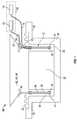
Fig. 1 is a schematic, elevational view in section of an embodiment of the disclosed dual coil loudspeaker system;Fig. 2 is a perspective view, partially in section, of another embodiment of the disclosed dual coil loudspeaker system; andFigs. 3A, 3B, and 3C are detail views in perspective of the releasable connection of the embodiment ofFig. 2 .- As shown in
Fig. 1 , a dual coil loudspeaker system, generally designated 10, may include a voice coil, generally designated 12, having afirst coil 14 configured to receive a first electrical signal overwires 15 from afirst source 16, and asecond coil 18 configured to receive a second electrical signal overwires 19 from asecond source 20, different from the first source. Theloudspeaker system 10 may include afield magnet 22 configured to generate a magnetic field that interacts with magnetic fields created by thefirst coil 14 andsecond coil 18, and adiaphragm 24 connected to thevoice coil 12 such that thediaphragm 24 is displaced in response to energization of at least one of thefirst coil 14 andsecond coil 18 by thefirst source 16 andsecond source 20, respectively. - The
system 10 also may include ahousing 26 that may support thefield magnet 22 and form amagnetic gap 28 with thevoice coil 12. In an embodiment, thehousing 26 may be made of steel, or other magnetic material that may conduct or generate a magnetic field. Thehousing 26 may include anannular flange 30 that may support a spider orsuspension 32 that may support and center thevoice coil 12 with respect to thehousing 26 andfield magnet 22. - In an embodiment, the
voice coil 12 may include a coil former in the form of acylindrical tube 34. Thetube 34 may be made of a non-conductive material, such as paper or plastic, and may be connected to thediaphragm 24. Thefirst coil 14 andsecond coil 18 may be mounted on thetube 12. In this configuration, thefirst coil 14 and thesecond coil 18 may be concentric with respect to thefield magnet 22, which in the embodiment may act as an inner pole piece. In an embodiment, thefirst coil 14 may be mounted on anouter surface 36 of thetube 34, and thesecond coil 18 may be mounted on aninner surface 38 of the tube. In the embodiment shown, thefirst coil 14 and thesecond coil 18 may be electrically isolated from each other. In an embodiment, thesecond coil 18 may be adjacent thefirst coil 14 in a radial dimension of thetube 34. In other embodiments, thefirst coil 14 may be mounted on theinner surface 38 and the second coil may be mounted on theouter surface 36 of thetube 34. In still other embodiments, thefirst coil 14 andsecond coil 18 both may be on theinner surface 38 orouter surface 36, and may be wound to overlap each other. - In an embodiment, the
first source 16 may be in the form of a first amplifier connected to transmit the first electrical signal to thefirst coil 14, and thesecond source 20 may be in the form of a second amplifier, different from the first amplifier, connected to transmit the second electrical signal to thesecond coil 18, such that the first coil and the second coil may be energized in unison to excite thediaphragm 24 to make the same sound vibration in phase. In another embodiment, thefirst source 16 may take the form of a first channel from anamplifier 40 connected to transmit the first electrical signal to thefirst coil 14, and thesecond source 20 may take the form of a second channel from the amplifier, different from the first channel, connected to transmit the second electrical signal to thesecond coil 18 such that the first coil and the second coil are energized in unison to excite thediaphragm 24 to make the same sound vibration in phase. In yet another embodiment, thefirst source 16 andsecond source 20 may be two channels of a stereo audio signal. - With either embodiment, in an application, the first electrical signal and the second electrical signal from the
first source 16 and thesecond source 20, respectively, may be substantially identical and in phase. In an embodiment, thefirst source 16 andsecond source 20 may be configured to transmit an audio signal to thefirst coil 14 andsecond coil 18 overwires - In an embodiment, the
diaphragm 24 may be made of a material selected from paper, plastic, composite, metal, and thin fiberglass sheet. In another embodiment, thediaphragm 24 may be replaced by a panel, generally designated 42, and wherein thetube 34 may include anannular drive pad 44 for attaching thevoice coil 12 to thepanel 42. As will be discussed in greater detail, thepanel 42 may comprise a portion of the cabin wall 45 of a vehicle 46. The vehicle 46 may be selected from an aircraft, a spacecraft, a land vehicle, and a marine vehicle. - As shown in
Fig. 2 , in an embodiment generally designated 10', the diaphragm may comprise aflat panel 42 of a type having acore 48 andinner sheet 50 coupled to an inner surface of the core and anouter sheet 52 coupled to an outer surface of the core. Thepanel 42 may include a weakened area, generally designated 54, defined by at least one, and in an embodiment a plurality, ofslots 56 formed through theinner sheet 50. The weakenedarea 54 may be configured to vibrate in response to electrical signals to thevoice coil 12 to generate sound vibrations. - The system 10' may include a
frame 58, which may contact the diaphragm in the form of thepanel 42. In an embodiment, theframe 58 may be attached to thepanel 42 by an adhesive. Theframe 58 may support themagnet 22. In an embodiment, theframe 58 may include a plurality of upwardly extendingfingers 60, each having a circumferentially extendinggroove 62 shaped to receive the outer periphery of theflange 30 of thehousing 26. Thesuspension 32 may extend from thetube 34 and be anchored to an underside of theflange 30. In an embodiment, thefingers 60 may be sufficiently flexible to allow upward and downward activities of thehousing 26. In an embodiment, thehousing 26 andvoice coil 12 may be releasably held by theframe 58. - In the embodiment 10' illustrated in
Fig. 2 , thevoice coil 12 may include adrive pad 44 that may include areleasable connection 64. Thereleasable connection 64 may be configured to releasably connect thetube 34 of thevoice coil 12 to thepanel 42. In an embodiment, thereleasable connection 64 may include alock base 66 that may be attached to thepanel 42, such as by an adhesive, and alock pad 68 that may be attached to thetube 12 and configured to be releasably attached to the lock base. - In an embodiment, the
lock base 66 may include a dynamicbuffer coupling pad 70 configured to connect the lock base to thediaphragm 42. In an embodiment, the dynamicbuffer coupling pad 70 may include at least one layer of double sided tape. Without being limited to any particular theory, the dynamicbuffer coupling pad 70 may introduce an elastic material with certain damping properties. Unlike the diaphragm 24 (Fig. 1 ), which may comprise a very light material, such as thin paper, the mass of apanel 42 may be several thousand times heavier. When a strong audio impulse is transmitted by theamplifiers voice coil 12, the voice coil may send a shock wave to thepanel 42 that starts from the center of the weakenedarea 54 to the edges, and bouncing back to the center again. Thus, the mass of theacting panel 42 may be in motion, unable to stop flexing for a short period of time, on the order of a fraction of a second. - In instances where the audio signal creates a deflection of the
panel 42 of a relatively large amplitude, when the amplitude bounces back toward the center of the weakenedarea 54, the delayed mechanical energy may collide with the next firing of a large amplitude signal by thevoice coil 12, causing an audio breakup, which may appear as a very noticeable audio distortion. This phenomenon may worsen withpanels 54 that are relatively stiff. In such cases, even lesser amplitude audio signals may cause distortion, making theresultant loudspeaker system 10, 10' unable to transmit relatively loud sound vibrations without distortion. - By adding a dynamic
buffer coupling pad 70 in between the attachment of thevoice coil 12 anddiaphragm 42, such a sonic confrontation may be reduced. The degree of softness of thepad 70 may be selected on a case-by-case basis, taking into consideration the power rating of thevoice coil 12, the size of thepanel 42, the stiffness of the panel and the weight of the panel. Thepad 70 may provide a combination of damping and spring function. Thepad 70 may be intended to temporarily store the feedback energy of thepanel 42. In one embodiment, such apad 70 may be made from very high bonding ("VHB") double sided tape manufactured by 3M Company of Saint Paul, Minnesota. Thepad 70 may, in embodiments, have a single layer, or up to two or three layers or more to achieve the desired spring property. In an embodiment, the dynamicbuffer coupling pad 70 may be made of an elastic damping material of a selected thickness, or semi-flexible epoxy. - As shown in
Figs. 3A, 3B, and 3C , thelock base 66 may include aflange 72 that may be mounted on the diaphragm, which in the embodiment ofFig. 2 may take the form of apanel 42. Thelock base 66 may include three radially projectingtabs 74 that may be spaced from theflange 72. Thelock pad 68 may include an upwardly extendingannular rib 76 that may be shaped to engage and be attached to thetube 34 of the voice coil 12 (seeFig. 2 ). Thelock pad 68 also may include three regularly inwardly extendingfingers 78 that may be shaped to engage thetabs 74 of thelock base 68 in a friction fit. - Accordingly, the
voice coil 12 andlock pad 68 may be releasably attached to thelock base 66 by centering and aligning the lock pad relative to the lock base, sliding the lock pad downwardly against the lock base, and rotating the lock pad in a clockwise direction, as shown inFig. 3B . This may cause thefingers 78 to slide beneath and press against thetabs 74 until, as shown inFig. 3C , thefingers 78 may be entirely underneath thetabs 74. In an embodiment, thetabs 74 may form a blind slot with theflange 72 that prevents further clockwise rotation of thelock pad 68 relative to thelock base 66. In an embodiment, the spacing between theflange 72 and thetab 74 may provide a frictional engagement with thefingers 78 so that thevoice coil 12 may be firmly attached to the diaphragm, which in the embodiment ofFigs. 2 and3A-C may be in the form of apanel 42. - In operation, the first and
second sources common amplifier 40, generate electrical signals, which in embodiments are audio signals, which are transmitted overwires second coils voice coil 12. The varying magnetic fields created by these audio signals may interact with the magnetic field of thefield magnet 22 and cause thevoice coil 12 to move back and forth in the direction of the magnetic gap 28 (Fig. 1 ) relative to thefield magnet 22. This may cause thediaphragm 24, which may be in the form ofpanel 42, to vibrate, thereby generating sound energy, which may be in the form of acoustic vibrations. - By utilizing a dual
coil loudspeaker system 10, 10', preexisting amplifiers that may not be particularly powerful may be employed, and their audio signals may be combined to power asingle voice coil 12. Thissystem 10, 10' may eliminate the need to employ and certify more powerful amplifiers to drive less efficient speakers, such as speakers that utilize a relatively heavyflat panel 42. - While the forms of apparatus and methods described herein constitute preferred embodiments of the dual coiled loudspeaker system, it is to be understood that modifications may be made therein without departing from the scope of the invention.
- Further, the disclosure comprises embodiments according to the following clauses:
- Clause 1. A dual coil loudspeaker system comprising: a voice coil having a first coil configured to receive a first electrical signal from a first source, and a second coil configured to receive a second electrical signal from a second source different from the first source; a field magnet configured to generate a magnetic field that interacts with magnetic fields created by the first coil and the second coil; and a diaphragm connected to the voice coil such that the diaphragm is displaced in response to energization of at least one of the first coil and the second coil.
- Clause 2. The dual coil loudspeaker system of clause 1, further comprising a frame connected to the diaphragm and supporting the magnet; and a spider connected to suspend the voice coil relative to the frame and center the voice coil relative to the magnet.
- Clause 3. The dual coil loudspeaker system of clause 1 or 2, wherein the field magnet includes an inner pole piece.
- Clause 4. The dual coil loudspeaker system of any preceding clause, wherein the first coil and the second coil are electrically isolated from each other.
- Clause 5. The dual coil loudspeaker system of any preceding clause, wherein the first coil and the second coil are concentric with respect to the inner pole piece.
- Clause 6. The dual coil loudspeaker system of any preceding clause, wherein the voice coil includes a tube connected to the diaphragm, and wherein the first coil and the second coil are mounted on the tube.
- Clause 7. The dual coil loudspeaker system of any preceding clause, wherein the first coil is mounted on one of an outer surface of the tube and an inner surface of the tube; and the second coil is mounted on one of the outer surface of the tube and the inner surface of the tube.
- Clause 8. The dual coil loudspeaker system of any preceding clause, wherein the second coil is adjacent the first coil in a radial dimension of the tube.
- Clause 9. The dual coil loudspeaker system of any preceding clause, wherein the voice coil includes a releasable connection configured to releasably connect the tube to the diaphragm.
Clause 10. The dual coil loudspeaker system of any preceding clause, wherein the releasable connection includes a lock base attached to the diaphragm; and a lock pad attached to the tube and configured to be releasably attached to the lock base.- Clause 11. The dual coil loudspeaker system of any preceding clause, further comprising a dynamic buffer coupling pad configured to connect the lock base to the diaphragm.
Clause 12. The dual coil loudspeaker system of any preceding clause, wherein the dynamic buffer coupling pad is selected from at least one layer of double-sided tape, and a layer of semi-flexible epoxy.- Clause 13. The dual coil loudspeaker system of any preceding clause, further comprising the first source including a first amplifier connected to transmit the first electrical signal to the first coil; and the second source including a second amplifier, different from the first amplifier, connected to transmit the second electrical signal to the second coil, such that the first coil and the second coil are energized in unison to excite the diaphragm to make the same sound vibration.
Clause 14. The dual coil loudspeaker system of any preceding clause, further comprising the first source including a first channel from an amplifier connected to transmit the first electrical signal to the first coil; and the second source including a second channel from the amplifier, different from the first channel, connected to transmit the second electrical signal to the second coil, such that the first coil and the second coil are energized in unison to excite the diaphragm to make the same sound vibration in phase.Clause 15. The dual coil loudspeaker system of any preceding clause, wherein the first electrical signal and the second electrical signal are substantially identical.Clause 16. The dual coil loudspeaker system of any preceding clause, wherein the diaphragm is made of a material selected from paper, plastic, metal, thin fiberglass sheet, and a panel having a core, an inner sheet coupled to an inner surface of the core and an outer sheet coupled to an outer surface of the core, the panel having a weakened area defined by at least one slot formed through the outer sheet.- Clause 17. A dual coil loudspeaker system comprising: an audio signal source including a first amplifier and a second amplifier; a voice coil having a first coil connected to receive a first audio signal from the first amplifier, and a second coil connected to receive a second electrical signal from the second amplifier, the first coil electrically isolated from the second coil; a field magnet configured to generate a magnetic field that interacts with magnetic fields created by the first coil and the second coil in response to the first audio signal and second audio signal, respectively; a diaphragm connected to the voice coil such that the diaphragm is displaced in response to energization of at least one of the first coil and the second coil in response to the first audio signal and the second audio signal, respectively; and the voice coil including a tube connected to the diaphragm, and wherein the first coil and the second coil are mounted concentrically on the tube.
Clause 18. The dual coil loudspeaker system of clause 17, further comprising an aircraft, and wherein the diaphragm is mounted to a cabin wall of the aircraft.Clause 19. The dual coil loudspeaker system ofclause 17 or 18, wherein the diaphragm includes a panel having a core, an inner sheet coupled to an inner surface of the core and an outer sheet coupled to an outer surface of the core, the panel having a weakened area defined by at least one slot formed through the outer sheet, and wherein the tube is centered on the weakened area, the panel being integral with the cabin wall.Clause 20. A method of generating acoustic vibrations with a dual coil loudspeaker system, the method comprising: transmitting a first acoustic signal from a first source to a first coil of a voice coil; simultaneously transmitting a second acoustic signal from a second source, different from the first source, to a second coil of the voice coil, the second acoustic signal identical to the first acoustic signal; moving the voice coil by generating varying magnetic fields from the first coil and the second coil in response to the first acoustic signal and the second acoustic signal that interact with a field magnet; and vibrating a diaphragm connected to the voice coil in response to moving the voice coil to generate acoustic vibrations.
Claims (12)
- A dual coil loudspeaker system (10, 10') comprising:a voice coil (12) having a first coil (14) configured to receive a first electrical signal from a first source (16), and a second coil (18) configured to receive a second electrical signal from a second source (20) different from the first source;a field magnet (22) configured to generate a magnetic field that interacts with magnetic fields created by the first coil and the second coil; anda diaphragm (24, 42) connected to the voice coil such that the diaphragm is displaced in response to energization of at least one of the first coil and the second coil,wherein the voice coil (12) includes a tube (34) connected to the diaphragm (24, 42), wherein the first coil (14) is mounted on one of an outer surface (36) of the tube (34) and an inner surface (38) of the tube; and the second coil (18) is mounted on the other one of the outer surface of the tube and the inner surface of the tube; and
wherein the second coil (18) is adjacent the first coil (14) in a radial dimension of the tube (34). - The dual coil loudspeaker system (10, 10') of claim 1, further comprising:a frame (58) connected to the diaphragm (24, 42) and supporting the magnet (22) ; anda spider (32) connected to suspend the voice coil (12) relative to the frame and center the voice coil relative to the magnet.
- The dual coil loudspeaker system (10, 10') of claim 1 or 2, wherein the field magnet (22) includes an inner pole piece.
- The dual coil loudspeaker system (10, 10') of any preceding claim, wherein the first coil (14) and the second coil (18) are electrically isolated from each other.
- The dual coil loudspeaker system (10, 10') of any preceding claim, wherein the first coil (14) and the second coil (18) are concentric with respect to the inner pole piece.
- The dual coil loudspeaker system (10, 10') of any preceding claim, wherein the voice coil (12) includes a releasable connection (64) configured to releasably connect the tube (34) to the diaphragm (24, 42).
- The dual coil loudspeaker system (10, 10') of claim 6, wherein the releasable connection (64) includes a lock base (66) attached to the diaphragm (24, 42); and a lock pad (68) attached to the tube (34) and configured to be releasably attached to the lock base.
- The dual coil loudspeaker system (10, 10') of any preceding claim, further comprising a dynamic buffer coupling pad (70) configured to connect the lock base (66) to the diaphragm (24,42).
- The dual coil loudspeaker system (10, 10') of any preceding claim, further comprising the first source (16) including a first amplifier connected to transmit the first electrical signal to the first coil (14); and the second source (20) including a second amplifier, different from the first amplifier, connected to transmit the second electrical signal to the second coil (18), such that the first coil and the second coil are energized in unison to excite the diaphragm (24, 42) to make the same sound vibration.
- The dual coil loudspeaker system (10, 10') of any preceding claim, further comprising the first source (16) including a first channel from an amplifier connected to transmit the first electrical signal to the first coil (14); and the second source (20) including a second channel from the amplifier, different from the first channel, connected to transmit the second electrical signal to the second coil (18), such that the first coil and the second coil are energized in unison to excite the diaphragm (24, 42) to make the same sound vibration in phase.
- The dual coil loudspeaker system (10, 10') of any preceding claim, wherein the first electrical signal and the second electrical signal are substantially identical.
- The dual coil loudspeaker system (10, 10') of any preceding claim, wherein the diaphragm (24, 42) is made of a material selected from paper, plastic, metal, thin fiberglass sheet, and a panel (42) having a core (48), an inner sheet (50) coupled to an inner surface of the core and an outer sheet (52) coupled to an outer surface of the core, the panel having a weakened area (54) defined by at least one slot (56) formed through the outer sheet.
Applications Claiming Priority (1)
| Application Number | Priority Date | Filing Date | Title |
|---|---|---|---|
| US13/972,500US9014413B2 (en) | 2013-08-21 | 2013-08-21 | Dual coil loudspeaker system |
Publications (2)
| Publication Number | Publication Date |
|---|---|
| EP2840805A1 EP2840805A1 (en) | 2015-02-25 |
| EP2840805B1true EP2840805B1 (en) | 2016-08-17 |
Family
ID=50942196
Family Applications (1)
| Application Number | Title | Priority Date | Filing Date |
|---|---|---|---|
| EP14172691.9ANot-in-forceEP2840805B1 (en) | 2013-08-21 | 2014-06-17 | Dual coil loudspeaker system |
Country Status (3)
| Country | Link |
|---|---|
| US (1) | US9014413B2 (en) |
| EP (1) | EP2840805B1 (en) |
| CA (1) | CA2854503C (en) |
Families Citing this family (5)
| Publication number | Priority date | Publication date | Assignee | Title |
|---|---|---|---|---|
| TWM488817U (en)* | 2014-07-01 | 2014-10-21 | jian-guo Hong | Dual coil speaker of mobile device |
| CN104902406A (en)* | 2015-05-07 | 2015-09-09 | 珠海市源声电子有限公司 | Coaxial same-phase double moving coil unit loudspeaker |
| KR102370183B1 (en)* | 2017-07-12 | 2022-03-03 | 엘지디스플레이 주식회사 | Display apparatus |
| CN109525924A (en)* | 2017-09-19 | 2019-03-26 | 惠州超声音响有限公司 | Loudspeaker with open induction coil |
| CN110446144B (en)* | 2019-07-22 | 2021-10-22 | 瑞声科技(新加坡)有限公司 | Sound production device |
Family Cites Families (45)
| Publication number | Priority date | Publication date | Assignee | Title |
|---|---|---|---|---|
| JPS5568795A (en) | 1978-11-20 | 1980-05-23 | Sony Corp | Speaker |
| EP0054945B1 (en) | 1980-12-19 | 1985-10-30 | Nissan Motor Co., Ltd. | Speaker for automotive vehicle audio system |
| US4551849A (en) | 1982-05-11 | 1985-11-05 | Nissan Motor Company, Limited | Vehicle panel speaker for automotive audio system utilizing part of a vehicle panel as a sound-producing medium |
| NL8303186A (en)* | 1983-09-15 | 1985-04-01 | Philips Nv | SPEAKER SYSTEM AND SPEAKER FOR USE IN A SPEAKER FOR CONVERTING AN ELECTRICAL SIGNAL INTO AN BIT IN AN ACOUSTIC SIGNAL. |
| US4586192A (en)* | 1984-01-27 | 1986-04-29 | Robert B. Welch | Soundstage boundary expansion system |
| US4897877A (en) | 1987-05-18 | 1990-01-30 | Oxford Speaker Company | Sub-woofer driver combination with dual voice coil arrangement |
| US6247551B1 (en) | 1990-08-04 | 2001-06-19 | The Secretary Of State For Defence In Her Britannic Majesty's Government Of The United Kingdom Of Great Britain And Northern Ireland | Panel-form loudspeaker |
| US6058196A (en) | 1990-08-04 | 2000-05-02 | The Secretary Of State For Defense In Her Britannic Majesty's Government Of The United Kingdom Of Great Britain And Northern Ireland | Panel-form loudspeaker |
| DE69106712T2 (en) | 1990-08-04 | 1995-06-08 | Secr Defence Brit | PANEL-SHAPED SPEAKER. |
| US5212732A (en)* | 1992-03-05 | 1993-05-18 | Lancer Electronics | Effects speaker system |
| US5699438A (en) | 1995-08-24 | 1997-12-16 | Prince Corporation | Speaker mounting system |
| US6188775B1 (en) | 1995-09-02 | 2001-02-13 | New Transducers Limited | Panel-form loudspeakers |
| US6519349B1 (en) | 1995-09-02 | 2003-02-11 | New Transducers Limited | Loudspeaker |
| US6304661B1 (en) | 1995-09-02 | 2001-10-16 | New Transducers Limited | Loudspeakers comprising panel-form acoustic radiating elements |
| US6320967B1 (en) | 1995-09-02 | 2001-11-20 | New Tranducers Limited | Passenger vehicles incorporating loudspeakers comprising panel-form acoustic radiating elements |
| US6198831B1 (en) | 1995-09-02 | 2001-03-06 | New Transducers Limited | Panel-form loudspeakers |
| KR19990044330A (en) | 1995-09-02 | 1999-06-25 | 헨리 에이지마 | Panel Loudspeakers |
| AU703061B2 (en) | 1995-09-02 | 1999-03-11 | New Transducers Limited | Vibration transducers |
| US6327369B1 (en) | 1995-09-02 | 2001-12-04 | New Transducers Limited | Loudspeakers comprising panel-form acoustic radiating elements |
| US5708719A (en) | 1995-09-07 | 1998-01-13 | Rep Investment Limited Liability Company | In-home theater surround sound speaker system |
| US6144746A (en) | 1996-02-09 | 2000-11-07 | New Transducers Limited | Loudspeakers comprising panel-form acoustic radiating elements |
| US6031926A (en) | 1996-09-02 | 2000-02-29 | New Transducers Limited | Panel-form loudspeakers |
| US6282298B1 (en) | 1996-09-03 | 2001-08-28 | New Transducers Limited | Acoustic device |
| GB2320393A (en) | 1996-12-11 | 1998-06-17 | Secr Defence | Panel form loudspeaker |
| GB9714050D0 (en) | 1997-07-03 | 1997-09-10 | New Transducers Ltd | Panel-form loudspeakers |
| EP1007390B1 (en) | 1997-09-03 | 2002-09-25 | New Transducers Limited | Trim panel comprising an integral acoustic system |
| DE19821861A1 (en) | 1998-05-15 | 1999-11-18 | Nokia Deutschland Gmbh | Device for dynamically exciting flat panel loudspeaker |
| US6782111B1 (en)* | 1998-07-09 | 2004-08-24 | Bose Corporation | Multiple voicecoil and driver transducing |
| US6237715B1 (en) | 1998-12-01 | 2001-05-29 | Dennis A. Tracy | Subwoofer assembly |
| DE19944802C2 (en) | 1999-09-20 | 2003-08-28 | Harman Audio Electronic Sys | door |
| US20020018575A1 (en) | 2000-03-23 | 2002-02-14 | Charles Bream | Panel-form loudspeakers |
| EP1170977A1 (en) | 2000-07-04 | 2002-01-09 | Tai-Yan Kam | Laminated composite panel-form loudspeaker |
| US6826285B2 (en) | 2000-08-03 | 2004-11-30 | New Transducers Limited | Bending wave loudspeaker |
| US7120263B2 (en) | 2001-03-23 | 2006-10-10 | New Transducers Limited | Bending wave acoustic radiator |
| US6681026B2 (en) | 2001-11-30 | 2004-01-20 | Tai-Yan Kam | Rectangular transducer for panel-form loudspeaker |
| US6929091B2 (en) | 2002-10-28 | 2005-08-16 | Sound Advance Systems, Inc. | Planar diaphragm loudspeaker and related methods |
| EP1480489A3 (en) | 2003-05-23 | 2009-07-01 | Alps Electric Co., Ltd. | Exciting device for producing sound |
| US7447322B2 (en) | 2004-01-13 | 2008-11-04 | Brookstone Purchasing, Inc. | Speaker having a transparent panel |
| US20060110001A1 (en) | 2004-11-24 | 2006-05-25 | Stephen Saint Vincent | Inertial voice type coil actuator systems |
| US7817810B2 (en) | 2005-08-03 | 2010-10-19 | The Boeing Company | Flat panel loudspeaker system |
| WO2007047442A1 (en) | 2005-10-13 | 2007-04-26 | Donnelly Corporation | Acoustical window assembly for vehicle |
| JP4784398B2 (en) | 2006-05-29 | 2011-10-05 | パナソニック株式会社 | Acoustic exciter and speaker using the same |
| US8139795B2 (en) | 2006-10-13 | 2012-03-20 | Airbus Deutschland Gmbh | Loudspeaker system for aircraft cabin |
| JP2009194467A (en) | 2008-02-12 | 2009-08-27 | Victor Co Of Japan Ltd | Voice coil and speaker |
| JP5392841B2 (en) | 2009-12-07 | 2014-01-22 | アルパイン株式会社 | Speaker device |
- 2013
- 2013-08-21USUS13/972,500patent/US9014413B2/ennot_activeExpired - Fee Related
- 2014
- 2014-06-17CACA2854503Apatent/CA2854503C/enactiveActive
- 2014-06-17EPEP14172691.9Apatent/EP2840805B1/ennot_activeNot-in-force
Also Published As
| Publication number | Publication date |
|---|---|
| CA2854503C (en) | 2017-05-02 |
| US20150055819A1 (en) | 2015-02-26 |
| CA2854503A1 (en) | 2015-02-21 |
| US9014413B2 (en) | 2015-04-21 |
| EP2840805A1 (en) | 2015-02-25 |
Similar Documents
| Publication | Publication Date | Title |
|---|---|---|
| EP2840805B1 (en) | Dual coil loudspeaker system | |
| EP3096536B1 (en) | Flat panel loudspeaker system | |
| US9906867B2 (en) | Surface acoustic transducer | |
| US11388523B2 (en) | Inertial exciters, drive units and loudspeakers | |
| US10252802B2 (en) | Flat panel loudspeaker system | |
| EP3378161A1 (en) | Surface acoustic transducer | |
| US20170193980A1 (en) | Systems and methods for providing an enhanced audible environment within an aircraft cabin | |
| GB2516367A (en) | Silencer and speaker device | |
| KR102032166B1 (en) | Panel excitation type speaker | |
| CN209787426U (en) | Vibration sound production device and electronic equipment | |
| EP3101911B1 (en) | Distributed mode loudspeaker damping oscillations within exciter feet | |
| US9025798B2 (en) | Multi-coaxial transducers and methods | |
| CN116261087A (en) | Loudspeaker | |
| US20060110001A1 (en) | Inertial voice type coil actuator systems | |
| WO2008029083A1 (en) | Bending wave panel loudspeakers | |
| US6983819B2 (en) | Entertainment sound panels | |
| US7672472B2 (en) | Audio transducer | |
| JP2012175240A (en) | Electrodynamic exciter | |
| US12250532B2 (en) | Loudspeaker with inertial exciter comprising a magnet assembly suspended from a mounting frame | |
| CN219659904U (en) | Loudspeaker capable of inhibiting rolling vibration | |
| US20200015019A1 (en) | Acoustic panel assembly | |
| HK1194583A (en) | Loudspeaker with force cancelling configuration | |
| HK1055528A (en) | Entertainment sound panels |
Legal Events
| Date | Code | Title | Description |
|---|---|---|---|
| PUAI | Public reference made under article 153(3) epc to a published international application that has entered the european phase | Free format text:ORIGINAL CODE: 0009012 | |
| 17P | Request for examination filed | Effective date:20140617 | |
| AK | Designated contracting states | Kind code of ref document:A1 Designated state(s):AL AT BE BG CH CY CZ DE DK EE ES FI FR GB GR HR HU IE IS IT LI LT LU LV MC MK MT NL NO PL PT RO RS SE SI SK SM TR | |
| AX | Request for extension of the european patent | Extension state:BA ME | |
| R17P | Request for examination filed (corrected) | Effective date:20150820 | |
| RBV | Designated contracting states (corrected) | Designated state(s):AL AT BE BG CH CY CZ DE DK EE ES FI FR GB GR HR HU IE IS IT LI LT LU LV MC MK MT NL NO PL PT RO RS SE SI SK SM TR | |
| GRAP | Despatch of communication of intention to grant a patent | Free format text:ORIGINAL CODE: EPIDOSNIGR1 | |
| INTG | Intention to grant announced | Effective date:20160125 | |
| GRAS | Grant fee paid | Free format text:ORIGINAL CODE: EPIDOSNIGR3 | |
| GRAA | (expected) grant | Free format text:ORIGINAL CODE: 0009210 | |
| AK | Designated contracting states | Kind code of ref document:B1 Designated state(s):AL AT BE BG CH CY CZ DE DK EE ES FI FR GB GR HR HU IE IS IT LI LT LU LV MC MK MT NL NO PL PT RO RS SE SI SK SM TR | |
| REG | Reference to a national code | Ref country code:GB Ref legal event code:FG4D | |
| REG | Reference to a national code | Ref country code:CH Ref legal event code:EP | |
| REG | Reference to a national code | Ref country code:IE Ref legal event code:FG4D | |
| REG | Reference to a national code | Ref country code:AT Ref legal event code:REF Ref document number:822084 Country of ref document:AT Kind code of ref document:T Effective date:20160915 | |
| REG | Reference to a national code | Ref country code:DE Ref legal event code:R096 Ref document number:602014003058 Country of ref document:DE | |
| REG | Reference to a national code | Ref country code:NL Ref legal event code:MP Effective date:20160817 | |
| REG | Reference to a national code | Ref country code:LT Ref legal event code:MG4D | |
| REG | Reference to a national code | Ref country code:AT Ref legal event code:MK05 Ref document number:822084 Country of ref document:AT Kind code of ref document:T Effective date:20160817 | |
| PG25 | Lapsed in a contracting state [announced via postgrant information from national office to epo] | Ref country code:IT Free format text:LAPSE BECAUSE OF FAILURE TO SUBMIT A TRANSLATION OF THE DESCRIPTION OR TO PAY THE FEE WITHIN THE PRESCRIBED TIME-LIMIT Effective date:20160817 Ref country code:NO Free format text:LAPSE BECAUSE OF FAILURE TO SUBMIT A TRANSLATION OF THE DESCRIPTION OR TO PAY THE FEE WITHIN THE PRESCRIBED TIME-LIMIT Effective date:20161117 Ref country code:HR Free format text:LAPSE BECAUSE OF FAILURE TO SUBMIT A TRANSLATION OF THE DESCRIPTION OR TO PAY THE FEE WITHIN THE PRESCRIBED TIME-LIMIT Effective date:20160817 Ref country code:FI Free format text:LAPSE BECAUSE OF FAILURE TO SUBMIT A TRANSLATION OF THE DESCRIPTION OR TO PAY THE FEE WITHIN THE PRESCRIBED TIME-LIMIT Effective date:20160817 Ref country code:LT Free format text:LAPSE BECAUSE OF FAILURE TO SUBMIT A TRANSLATION OF THE DESCRIPTION OR TO PAY THE FEE WITHIN THE PRESCRIBED TIME-LIMIT Effective date:20160817 Ref country code:RS Free format text:LAPSE BECAUSE OF FAILURE TO SUBMIT A TRANSLATION OF THE DESCRIPTION OR TO PAY THE FEE WITHIN THE PRESCRIBED TIME-LIMIT Effective date:20160817 Ref country code:NL Free format text:LAPSE BECAUSE OF FAILURE TO SUBMIT A TRANSLATION OF THE DESCRIPTION OR TO PAY THE FEE WITHIN THE PRESCRIBED TIME-LIMIT Effective date:20160817 | |
| PG25 | Lapsed in a contracting state [announced via postgrant information from national office to epo] | Ref country code:LV Free format text:LAPSE BECAUSE OF FAILURE TO SUBMIT A TRANSLATION OF THE DESCRIPTION OR TO PAY THE FEE WITHIN THE PRESCRIBED TIME-LIMIT Effective date:20160817 Ref country code:SE Free format text:LAPSE BECAUSE OF FAILURE TO SUBMIT A TRANSLATION OF THE DESCRIPTION OR TO PAY THE FEE WITHIN THE PRESCRIBED TIME-LIMIT Effective date:20160817 Ref country code:GR Free format text:LAPSE BECAUSE OF FAILURE TO SUBMIT A TRANSLATION OF THE DESCRIPTION OR TO PAY THE FEE WITHIN THE PRESCRIBED TIME-LIMIT Effective date:20161118 Ref country code:PT Free format text:LAPSE BECAUSE OF FAILURE TO SUBMIT A TRANSLATION OF THE DESCRIPTION OR TO PAY THE FEE WITHIN THE PRESCRIBED TIME-LIMIT Effective date:20161219 Ref country code:AT Free format text:LAPSE BECAUSE OF FAILURE TO SUBMIT A TRANSLATION OF THE DESCRIPTION OR TO PAY THE FEE WITHIN THE PRESCRIBED TIME-LIMIT Effective date:20160817 Ref country code:PL Free format text:LAPSE BECAUSE OF FAILURE TO SUBMIT A TRANSLATION OF THE DESCRIPTION OR TO PAY THE FEE WITHIN THE PRESCRIBED TIME-LIMIT Effective date:20160817 Ref country code:ES Free format text:LAPSE BECAUSE OF FAILURE TO SUBMIT A TRANSLATION OF THE DESCRIPTION OR TO PAY THE FEE WITHIN THE PRESCRIBED TIME-LIMIT Effective date:20160817 | |
| PG25 | Lapsed in a contracting state [announced via postgrant information from national office to epo] | Ref country code:RO Free format text:LAPSE BECAUSE OF FAILURE TO SUBMIT A TRANSLATION OF THE DESCRIPTION OR TO PAY THE FEE WITHIN THE PRESCRIBED TIME-LIMIT Effective date:20160817 Ref country code:EE Free format text:LAPSE BECAUSE OF FAILURE TO SUBMIT A TRANSLATION OF THE DESCRIPTION OR TO PAY THE FEE WITHIN THE PRESCRIBED TIME-LIMIT Effective date:20160817 | |
| REG | Reference to a national code | Ref country code:DE Ref legal event code:R097 Ref document number:602014003058 Country of ref document:DE | |
| PG25 | Lapsed in a contracting state [announced via postgrant information from national office to epo] | Ref country code:CZ Free format text:LAPSE BECAUSE OF FAILURE TO SUBMIT A TRANSLATION OF THE DESCRIPTION OR TO PAY THE FEE WITHIN THE PRESCRIBED TIME-LIMIT Effective date:20160817 Ref country code:SK Free format text:LAPSE BECAUSE OF FAILURE TO SUBMIT A TRANSLATION OF THE DESCRIPTION OR TO PAY THE FEE WITHIN THE PRESCRIBED TIME-LIMIT Effective date:20160817 Ref country code:BE Free format text:LAPSE BECAUSE OF FAILURE TO SUBMIT A TRANSLATION OF THE DESCRIPTION OR TO PAY THE FEE WITHIN THE PRESCRIBED TIME-LIMIT Effective date:20160817 Ref country code:SM Free format text:LAPSE BECAUSE OF FAILURE TO SUBMIT A TRANSLATION OF THE DESCRIPTION OR TO PAY THE FEE WITHIN THE PRESCRIBED TIME-LIMIT Effective date:20160817 Ref country code:BG Free format text:LAPSE BECAUSE OF FAILURE TO SUBMIT A TRANSLATION OF THE DESCRIPTION OR TO PAY THE FEE WITHIN THE PRESCRIBED TIME-LIMIT Effective date:20161117 Ref country code:DK Free format text:LAPSE BECAUSE OF FAILURE TO SUBMIT A TRANSLATION OF THE DESCRIPTION OR TO PAY THE FEE WITHIN THE PRESCRIBED TIME-LIMIT Effective date:20160817 | |
| PLBE | No opposition filed within time limit | Free format text:ORIGINAL CODE: 0009261 | |
| STAA | Information on the status of an ep patent application or granted ep patent | Free format text:STATUS: NO OPPOSITION FILED WITHIN TIME LIMIT | |
| REG | Reference to a national code | Ref country code:FR Ref legal event code:PLFP Year of fee payment:4 | |
| 26N | No opposition filed | Effective date:20170518 | |
| PG25 | Lapsed in a contracting state [announced via postgrant information from national office to epo] | Ref country code:SI Free format text:LAPSE BECAUSE OF FAILURE TO SUBMIT A TRANSLATION OF THE DESCRIPTION OR TO PAY THE FEE WITHIN THE PRESCRIBED TIME-LIMIT Effective date:20160817 | |
| PG25 | Lapsed in a contracting state [announced via postgrant information from national office to epo] | Ref country code:MC Free format text:LAPSE BECAUSE OF FAILURE TO SUBMIT A TRANSLATION OF THE DESCRIPTION OR TO PAY THE FEE WITHIN THE PRESCRIBED TIME-LIMIT Effective date:20160817 | |
| REG | Reference to a national code | Ref country code:CH Ref legal event code:PL | |
| REG | Reference to a national code | Ref country code:IE Ref legal event code:MM4A | |
| PG25 | Lapsed in a contracting state [announced via postgrant information from national office to epo] | Ref country code:IE Free format text:LAPSE BECAUSE OF NON-PAYMENT OF DUE FEES Effective date:20170617 Ref country code:LU Free format text:LAPSE BECAUSE OF NON-PAYMENT OF DUE FEES Effective date:20170617 Ref country code:CH Free format text:LAPSE BECAUSE OF NON-PAYMENT OF DUE FEES Effective date:20170630 Ref country code:LI Free format text:LAPSE BECAUSE OF NON-PAYMENT OF DUE FEES Effective date:20170630 | |
| REG | Reference to a national code | Ref country code:FR Ref legal event code:PLFP Year of fee payment:5 | |
| PG25 | Lapsed in a contracting state [announced via postgrant information from national office to epo] | Ref country code:MT Free format text:LAPSE BECAUSE OF NON-PAYMENT OF DUE FEES Effective date:20170617 | |
| PG25 | Lapsed in a contracting state [announced via postgrant information from national office to epo] | Ref country code:AL Free format text:LAPSE BECAUSE OF FAILURE TO SUBMIT A TRANSLATION OF THE DESCRIPTION OR TO PAY THE FEE WITHIN THE PRESCRIBED TIME-LIMIT Effective date:20160817 | |
| PG25 | Lapsed in a contracting state [announced via postgrant information from national office to epo] | Ref country code:HU Free format text:LAPSE BECAUSE OF FAILURE TO SUBMIT A TRANSLATION OF THE DESCRIPTION OR TO PAY THE FEE WITHIN THE PRESCRIBED TIME-LIMIT; INVALID AB INITIO Effective date:20140617 | |
| PG25 | Lapsed in a contracting state [announced via postgrant information from national office to epo] | Ref country code:CY Free format text:LAPSE BECAUSE OF FAILURE TO SUBMIT A TRANSLATION OF THE DESCRIPTION OR TO PAY THE FEE WITHIN THE PRESCRIBED TIME-LIMIT Effective date:20160817 | |
| PG25 | Lapsed in a contracting state [announced via postgrant information from national office to epo] | Ref country code:MK Free format text:LAPSE BECAUSE OF FAILURE TO SUBMIT A TRANSLATION OF THE DESCRIPTION OR TO PAY THE FEE WITHIN THE PRESCRIBED TIME-LIMIT Effective date:20160817 | |
| PG25 | Lapsed in a contracting state [announced via postgrant information from national office to epo] | Ref country code:TR Free format text:LAPSE BECAUSE OF FAILURE TO SUBMIT A TRANSLATION OF THE DESCRIPTION OR TO PAY THE FEE WITHIN THE PRESCRIBED TIME-LIMIT Effective date:20160817 | |
| PG25 | Lapsed in a contracting state [announced via postgrant information from national office to epo] | Ref country code:IS Free format text:LAPSE BECAUSE OF FAILURE TO SUBMIT A TRANSLATION OF THE DESCRIPTION OR TO PAY THE FEE WITHIN THE PRESCRIBED TIME-LIMIT Effective date:20161217 | |
| PGFP | Annual fee paid to national office [announced via postgrant information from national office to epo] | Ref country code:GB Payment date:20220628 Year of fee payment:9 | |
| PGFP | Annual fee paid to national office [announced via postgrant information from national office to epo] | Ref country code:FR Payment date:20220627 Year of fee payment:9 | |
| PGFP | Annual fee paid to national office [announced via postgrant information from national office to epo] | Ref country code:DE Payment date:20220629 Year of fee payment:9 | |
| REG | Reference to a national code | Ref country code:DE Ref legal event code:R119 Ref document number:602014003058 Country of ref document:DE | |
| GBPC | Gb: european patent ceased through non-payment of renewal fee | Effective date:20230617 | |
| PG25 | Lapsed in a contracting state [announced via postgrant information from national office to epo] | Ref country code:DE Free format text:LAPSE BECAUSE OF NON-PAYMENT OF DUE FEES Effective date:20240103 Ref country code:GB Free format text:LAPSE BECAUSE OF NON-PAYMENT OF DUE FEES Effective date:20230617 | |
| PG25 | Lapsed in a contracting state [announced via postgrant information from national office to epo] | Ref country code:FR Free format text:LAPSE BECAUSE OF NON-PAYMENT OF DUE FEES Effective date:20230630 |